thermal analysis of ceramic ball bearing and …...page 459 thermal analysis of ceramic ball bearing...
TRANSCRIPT
Page 459
Thermal Analysis of Ceramic Ball Bearing and Conventional Ball
Bearing Using Analytical and FEM
Koneti Satya Prasanna
M.Tech (Thermal) Student
Department of Mechanical
Engineering
Adarsh College of Engineering
Chebrolu, Kakinada.
A.Rupesh Venkata Ramana
Assistant Professor
Department of Mechanical
Engineering
Adarsh College of Engineering
Chebrolu, Kakinada.
Dr. T. Dharma Raju
Principal
Department of Mechanical
Engineering
Adarsh College of Engineering
Chebrolu, Kakinada.
ABSTRACT
The overall objective of this study was to evaluate and
compare the thermal analysis and performance of
ceramic ball bearing and conventional ball bearing.
In this study a thermal analysis was conducted on
ceramic ball bearing and conventional ball bearing.
A ball bearing is a type of rolling-element bearing
that uses balls to maintain the separation between the
moving parts of the bearing. The purpose of a ball
bearing is to reduce rotational friction and support
radial and axial loads. It achieves this by using at
least two races to contain the balls and transmit the
loads through the balls. Ball bearings tend to have
lower load capacity for their size than other kinds of
rolling-element bearings due to the smaller contact
area between the balls and races. However, the
bearing exhibit heat when they are in contact as they
experience friction.
To analyze the heat transfer in a ceramic and
conventional ball bearing and to study the heat
dissipation by varying materials for bearings,
temperature profile, and thermal gradient occurring
in a bearing as a function of rotational speed.
Thermal Analysis: The Finite Element Method
(FEM) and Analytical was used to analyze the heat
flow and other parameters in a bearing. Modelling of
the system was done using CATIAV5. The analysis
was done to study the heat dissipation in the bearing
for various materials.
Production of many metals is aided by a production
technique also referred to as thermal analysis. In this
project thermal analysis between two bearings are
carried out and the results are tabulated and
compared. This project also helps in learning
CATIAV5 and ANSYS software’s. Bearing Materials
- Ceramics, Chrome Steels &Stainless Steels
1. INTRODUCTION
A ball bearing is a type of rolling element bearing that
uses balls to maintain the separation between
the bearing races. The purpose of a ball bearing is to
reduce rotational friction and
support radial and axial loads. It achieves this by
using at least two races to contain the balls and
transmit the loads through the balls. In most
applications, one race is stationary and the other is
attached to the rotating assembly (e.g., a hub or
shaft). As one of the bearing races rotates it causes the
balls to rotate as well. Because the balls are rolling
they have a much lower coefficient of friction than if
two flat surfaces were sliding against each other. Ball
bearings tend to have lower load capacity for their size
than other kinds of rolling-element bearings due to the

Page 460
smaller contact area between the balls and races.
However, they can tolerate some misalignment of the
inner and outer races.
1.2 History and development of bearings:
A bearing is a machine element designed to fix, guide
or hold moving parts and to reduce friction.
Accordingly, bearings permit machine parts to rotate
or move in a straight line relative to one another free of
the friction created by rotational or linear motion. In
most cases, one of the machine parts is fixed and the
bearing acts as a support for the moving member. They
are used in various applications including airplanes,
automobiles, machine tools, precision instruments,
household appliances, etc., none of which could
operate effectively or efficiently without them.
Bearings can be made of ceramic, sapphire or glass.
1.3 Common designs:
There are several common designs of ball bearing,
each offering various trade-offs. They can be made
from many different materials, including: stainless
steel, chrome steel, and ceramic (silicon nitride
(Si3N4)). A hybrid ball bearing is a bearing with
ceramic balls and races of metal.
1.4 Angular contact:
An angular contact ball bearing uses axially
asymmetric races. An axial load passes in a straight
line through the bearing, whereas a radial load takes an
oblique path that tends to want to separate the races
axially. So the angle of contact on the inner race is the
same as that on the outer race.
Angular contact bearings better support "combined
loads" (loading in both the radial and axial directions)
and the contact angle of the bearing should be matched
to the relative proportions of each.
2. TYPES OF BEARINGS:
BALL BEARINGS
ROLLER BEARINGS
THRUST BEARINGS
2.1 Materials and Methods:
Based on the literature review, the design and process
parameters were selected. The steady state thermal
solution was obtained. The static structural solutions
were obtained. Figure 1 shows the flow chart for
thermal and structural solutions.
Figure 2.1 shows the flow chart for thermal and
structural solutions.
3. Selection of the Bearing:
A specific condition of the ball bearing was
taken and the design calculation was done.
The ball bearing was selected accordingly. A
simply supported shaft, diameter 20mm, with
a load of 10kN in the middle with the axial
load of 3kN was taken. The speed of the shaft
was taken as 440rpm. Bearing was selected for
1000 hours of rotation. The radial and axial
load factor selection are given in Table .1
r = 5 kN
Pa = 3 kN
Life of the Bearing in millions of revolution.
L10 =
= 86.4
Equivalent load on the bearing is given by,
Pe = X. Pr + Y. Pa
The X value and Y value were determined
from the chart. The factor, Co was obtained
Page 461
from the bearing catalogue. Co =5 kN;
referring the bearing catalogue at d = 20mm
𝑃𝑎
𝐶𝑜=3
5= 0.6
From the above table e = 0.45 by interpolation.
𝑃𝑎
𝑃𝑟=3
5= 0.6 < 𝑒
From the above table X = 1 and Y = 0
Equivalent radial load, Pe = X. Pr + Y. Pa
3.1. Heat Generation in the Bearing:
The major source of heat generation is the machining
process and the friction between the balls and the
races. The major portion of the heat is taken away by
the coolant and the chips. In ball bearings heat is
generated by three sources. First is the load related
heat generation, second source is the viscous shear of
lubricants between the solid bodies, known as viscous
heat dissipation. The third source of heat is known as
spin related heat generation. Considering this,
analytical formulation for heat generation in a bearing
was developed. The heat generated in a bearing is
given as
Hf= 1x10⁻⁴ . n. M
where, Hfis the heat generation due to friction in
Watts, n is the rotational speed (rpm), M is the total
frictional torque (N mm). Rotational speeds of 50,100
,150,200,250,300,350,400,450,500,550 were taken and
the total frictional torque as 100 N-mm. The internal
heat generation can be calculated by using the formula,
Internal Heat Generation = Hf/ V. The volume of the
Ball bearing was calculated as 56.54 mm3. The values
were tabulated and the internal heat generation was
calculated. The internal heat generation for different
speeds is shown
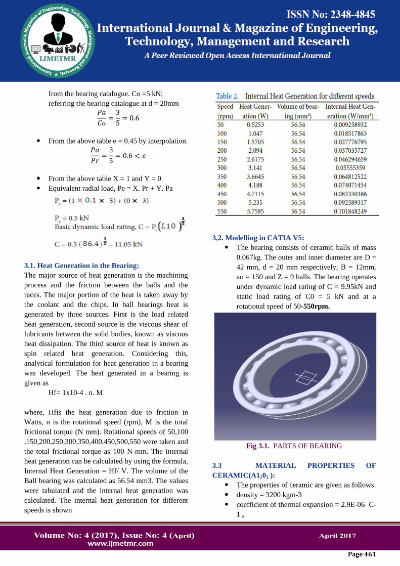
3,2. Modelling in CATIA V5:
The bearing consists of ceramic balls of mass
0.067kg. The outer and inner diameter are D =
42 mm, d = 20 mm respectively, B = 12mm,
ao = 150 and Z = 9 balls. The bearing operates
under dynamic load rating of C = 9.95kN and
static load rating of C0 = 5 kN and at a
rotational speed of 50-550rpm.
Fig 3.1. PARTS OF BEARING
3.3 MATERIAL PROPERTIES OF
CERAMIC(A1203 ):
The properties of ceramic are given as follows.
density = 3200 kgm-3
coefficient of thermal expansion = 2.9E-06 C-
1 ,

Page 462
Thermal Conductive = 36 (W/mK) at 20° C
Young’s modulus = 320E9 Pa,
Poisson’s ratio = 0.27
3.4. MATERIAL PROPERTIES OF CHROME
STEELS:
The properties of CHROME STEELS are
given as follows.
density = 8,050 kg/m3
coefficient of thermal expansion = 9.6 x 10-
6 m/m-deg C
Thermal Conductive = 61 (W/mK) at 20° C
Young’s modulus = 180 GPa
Poisson’s ratio = 0.27-0.30
3.5. MATERIAL PROPERTIES OF STAINLESS
STEELS:
The properties of STAINLESS STEELS are
given as follows.
density = 7.85 g/ cm³
coefficient of thermal expansion = 13.0 x 10-
6 m/m-deg C
Thermal Conductive = 16.63 (W/mK) at 20°
C
Young’s modulus = 200 GPa
Poisson’s ratio = 0.30–0.31
4. Ansys Results:
Model imported into Ansys:
Fig 4.1. Model is imported into Ansys in the
format of *.Stp
Fig 4.2 Solid Mesh model
CASE 1:
Using Material as CERAMIC(A1203 ) and speed range
of 50, 250 & 550 RPM. Thermal Analysis is carried
out on ball bearing:
Fig 4.3 Input load Heat Generation and Convection
load shown
Fig 4.4 Temputure distrubition of ball bearing for
speed of 50 RPM
Temputure distrubition of ball bearing for speed of 50
RPM and Heat Gearation of 0.00925 W/mm3
21.12 to 36.36 0 C

Page 463
Fig 4.5 Heat Flux distrubition of ball bearing for speed
of 50 RPM
Heat Flux distrubition of ball bearing for speed of 50
RPM and Heat Gearation of 0.00925 W/mm3
is in
range of 3.37 E-6 to 0.0876 W/mm2
CASE-1.2: Speed with 150 RPM and Heat generation
with 0.0277W/mm3
Fig 4.6 Temputure distrubition of ball bearing for
speed of 250 RPM
Temputure distrubition of ball bearing for speed of 250
RPM and Heat Gearation of 0.0277W/mm319.37 to
64.98 0 C
Fig 4.7 Heat Flux distrubition of ball bearing for speed
of 150 RPM
Heat Flux distrubition of ball bearing for speed of 150
RPM and Heat Gearation of 0.0277W/mm3
is in
range of 1.01 E-5 to 0.2623 W/mm2
CASE-1.3: Speed with 250 RPM and Heat generation
with 0.04629W/mm3
Fig 4.8 Temputure distrubition of ball bearing for
speed of 250 RPM
Temputure distrubition of ball bearing for speed of 250
RPM and Heat Gearation of 0.04629W/mm317.61 to
93.831 0 C
Fig 4.9 Heat Flux distrubition of ball bearing for speed
of 250 RPM
Heat Flux distrubition of ball bearing for speed of 250
RPM and Heat Gearation of 0.04629 W/mm3
is in
range of 1.68 E-6 to 0.4384 W/mm2
CASE-1.4: Speed with 350 RPM and Heat generation
with 0.0648W/mm3

Page 464
Fig 4.10 Temputure distrubition of ball bearing for
speed of 350 RPM
Temputure distrubition of ball bearing for speed of 350
RPM and Heat Gearation of 0.0648W/mm315.865 to
122.55 0 C
Fig 4.11 Heat Flux distrubition of ball bearing for
speed of 350 RPM
Heat Flux distrubition of ball bearing for speed of 350
RPM and Heat Gearation of 0.0648W/mm3
is in
range of 2.36E-5 to 0 0.6137 W/mm2
CASE1. 5: Speed with 550 RPM and Heat generation
with 0.10184W/mm3
Fig 4.12 Temputure distrubition of ball bearing for
speed of 550 RPM
Temputure distrubition of ball bearing for speed of 550
RPM and Heat Gearation of 0.10184W/mm3
12.35 to 180.03 0 C
Fig 4.13 Heat Flux distrubition of ball bearing for
speed of 550 RPM
Heat Flux distrubition of ball bearing for speed of 550
RPM and Heat Gearation of 0.10184 W/mm3
is in
range of 3.71 E-6 to 0.9646 W/mm2
Table 4.1 : Result table for max Temp and max
Heat flux

Page 465
are plotted Fig: 4.1 At speed 50 rpm material VS
Temperature
Fig: 4.2 At speed 50 rpm material VS Heat flux are
plotted
Fig: 4.3 At speed 150 rpm material VS Temperature
are plotted
Fig: 4.4 At speed 150 rpm material VS Heat flux are
plotted
Fig: 4.5 At speed 250 rpm material VS Temperature
are plotted
Fig: 4.6 At speed 250 rpm material VS Heat flux are
plotted
Fig: 4.7 At speed 350 rpm material VS Temperature
are plotted
26283032343638
TEM
PER
ATU
RE
MATERIALM VS MAXIMU TEMPERATURE -SPEED 50
RPM
MAX TEMP (oC)
0.08680.087
0.08720.08740.08760.0878
A1
20
3 …
CR
ST
N1
SS N
1
HEA
T FL
UX
MATERIALM VS MAXIMU HEAT
FLUX -SPEED 50 …
MAX HEAT FLUX(W/MM2)
0
20
40
60
80
TEM
PER
ATU
RE
MATERIALM VS MAXIMU TEMPERATURE - SPEED 150
RPM
MAX TEMP (oC)
0.25950.26
0.26050.261
0.26150.262
0.2625
HEA
T FL
UX
MATERIALM VS MAXIMU HEAT FLUX -SPEED 150 RPM
MAX HEAT FLUX(W/MM2)
020406080
100
TEM
PER
ATU
RE
MATERIALM VS MAXIMU TEMPERATURE - SPEED 250
RPM
MAX TEMP (oC)
0.4340.4360.438
0.44
A1
20
3 …
CR
ST
N3
SS N
3
HEA
T FL
UX
MATERIALM VS MAXIMU HEAT FLUX -
SPEED 250 RPM
MAX HEAT FLUX(W/MM2)

Page 466
Fig: 4.8 At speed 350 rpm material VS Heat flux are
plotted
Fig: 4.9 t speed 550 rpm material VS Temperature
are plotted
Fig: 4.10 At speed 550 rpm material VS Heat flux are
plotted
CONCLUSION:
The heat generation rate & temperature profile of the
bearing were measured. The simulation was
performed, and the temperature increases with heat
generation. The effects of temperature for different
bearing speeds are analyzed and the rotational speeds
have major effect on the temperature which tends to
increase with the increase of speeds. By varying
various materials like Al2O3, Cr steel, Steel are
calculated .From the results table best suit material
order are Al2O3, Cr Steel , SS and. Stage speeds of
50,150, 250, 350 & 550 RPM are studied and heat
generation is calculated accordingly.
The flash temperature and friction heat of the hybrid
and steel bearings were theoretically analyzed. The
hybrid ceramic bearings produce less heat and lower
temperatures for high-speed conditions.
A thermal model is developed to study the heat
generation rate, temperature distribution, deformation
and thermal stress occurred in the bearing system at
various stages with rotational speed as parameter and
preload load applied to a feed system .
Based on the characteristics of dynamic behavior of
the bearing system, the thermal stress simulation is
conducted, and it is observed from the simulation that
the temperature in the bearing increases with increase
0.607
0.608
0.609
0.61
0.611
0.612
0.613
0.614
A1203 N4
CR ST N4
SS N4
HEA
T FL
UX
MATERIALM VS MAXIMU HEAT FLUX -SPEED 350 RPM
MAX HEAT FLUX(W/MM2)
050
100150
TEM
PER
ATU
RE
MATERIALM VS MAXIMU TEMPERATURE - SPEED 350
RPM
MAX TEMP (oC)
0
50
100
150
200
A1203 N5
CR ST N5 SS N5
TEM
PER
ATU
RE
MATERIALM VS MAXIMU TEMPERATURE - SPEED 550
RPM
MAX TEMP (oC)
0.954
0.956
0.958
0.96
0.962
0.964
0.966
A1203 N5
CR ST N5
SS N5
Наз
ван
ие
оси
MATERIALM VS MAXIMU HEAT FLUX -SPEED 550 RPM
MAX HEAT FLUX(W/MM2)
Page 467
in heat generation developed by bearing and also it is
found that bearing inner ring temperature is higher
than the outer ring temperature due to centrifugal
forces that make inner ring contact forces and their
corresponding heat generation rate higher than those of
the outer ring. Further the increase of rotation speed
the inner ring centrifugal displacement value increases
greatly, this increase in inner ring centrifugal
displacement causes larger contact deformation and
stress. Furthermore, the effect of the inner ring
centrifugal displacement is larger on inner raceway
than on outer raceway.
The temperature distribution model is a wide covering
one because it includes the thermal transfer between
ball and races and also the heat generated both by the
viscous friction in lubricant film and the boundary
fiction on the asperity contact.
By result table, temperature and heat flux distribution
plot . Cr Steel is best result found for various speed of
bearing. By using this as per speed of bearings, we can
use bearing with combination of speed vs material.
REFERENCE:
1. Anbazhagan AMS, AnandMD. Design and crack
analysis of pressure vessel saddles using finite
element method. In-
dianJournalofScienceandTechnology.2016Jun;9(2
1):1– 12.
2. Krishnamani S, MohanrajT. Thermal analysis of
ceramic coated aluminum alloy piston using finite
element meth- od. Indian Journal of Science and
Technology. 2016 Jun; 9(22):1–5.
3. AlfaresMA,Abdallah,ElsharkawyA.Effectsofaxial
pre- loading of angular contact ball bearings on
the dynamics of a grinding machine spindle
system. Journal ofMaterials
ProcessingTechnology.2003;136:48–59.
4. JedrzejewskiJ,KwasnyW.Modelingofangularconta
ctball bearings and axial displacements for high-
speed spindles.
ManufacturingTechnology.2010;59:377–82.
5. Bao-min W, Xue-Song M, Chi-bing H. Effect of
inner ring centrifugal displacement on the
dynamic characteristics of high-speed angular
contact ball bearing. International Conference on
Mechatronics and Automation;2010.
6. GaoJ, Zhang R. Contact simulation of thrust ball
bearing
basedonANSYS.AdvancedMaterialsResearch.201
0;154– 155:1629–33.
7. Jin C, Wu B, HuY. Heat generation modelling of
ball bear- ing based on internal load distribution.
TribologyInterna- tional.2011.
8. Guo B, Han YQ, Lei WJ. Finite element analysis
ofhybrid ceramic ball bearing contact. Key
Kngineering Materials. 2011; 474-476:2064-70.
9. Wang C, YulW, Ren C. An accurate method for
calculat-
ingthecontactsubsurfacestressfieldofhybridcerami
cball
bearing.SolidStatePhenomena.2011;175:215–18
10. Yu DM, ShangbCP, Wang D, Gao ZH. Bearing
loadsstudy forhigh-
speedmotorizedspindle.KeyEngineeringMateri-
als. 2011;480–481:1511–15.
Author Details:
Koneti Satya Prasanna, M.Tech.[thermal] student,
Department of Mechanical Engineering , Adarsh
college of Engineering, Chebrolu, Kakinada.
Dr. T. Dharma Raju was born in Andhra Pradesh,
INDIA. He has received P.hd. from JNTU
HYDERABAD,TELANGANA, INDIA. He is
working as Principal of Adarsh college of
engineering ,chebrolu, Kakinada. India
A.Rupesh Venkata Ramana, Asst. Professor
Department of Mechanical Engineering Adarsh
College of Engineering, Chebrolu, Kakinada