therejuvenator - amiga-storage.net
TRANSCRIPT

TheRejuvenatorby Expert Services
Installation Manual
Designed by:Greg Tibbs

Warranty
Expert Services warrants registered boards for a period of 90 days from the date of purchaseunless the board is installed by Expert Services in which case the registered board will bewarranted for a period of 1 year. If, during that time, the board fails for reasons which, in theopinion of Expert Services, are not the result of accidental or intentional abuse, the board will berepaired or replaced free of charge and in a timely fashion.
If the board fails for reasons other than abuse outside of the warranty period, the board will berepaired for a flat fee of $95.00. This does not apply to replacement of the custom chips, whichwill be billed at their current price.
If the board fails for reasons of abuse at any time, the factory will charge a nonrefundable fee of$40.00 to inspect the board and generate an estimate for repairs. The customer may then elect tohave the board repaired for the estimated price or returned to them at no additional charge.
Trademarks
Amiga®, KickStart® and WorkBench® are registered trademarks of Commodore BusinessMachines, Inc. flickerFixer is a trademark of MicroWay.The Rejuvenator and the Expert Services logo are trademarks of Expert Services.
How To Get In Touch With Us
Mail: Expert Services5912 Centennial CircleFlorence, KY 41042
Phone: 606-371-9690 Voice606-371-9691 FAX
ii
Table of Contents
Warranty................................................................................................................................ iiProprietary Statements and Notices....................................................................................... ii
Section 1 - Introduction....................................................................................................... 1Technical Abilities..................................................................................................... 1Things Needed for Installation.................................................................................. 1Paris Supplied............................................................................................................ 2Static Handling Precautions....................................................................................... 2Glossary..................................................................................................................... 2
Section 2 - Amiga 1000 Disassembly.................................................................................. 2Amiga 1000 Rejuvenator Installation........................................................................ 5Testing....................................................................................................................... 7ROM Option.............................................................................................................. 8Fast Memory When Kickstart Disk Mode is Selected............................................... 9Expansion Peripherals................................................................................................ 10Battery........................................................................................................................11Real Time Clock Adjustment................................................................................... 11Amiga 1000 Reassembly........................................................................................... 11Care in Travel............................................................................................................ 13
Section 3 - Video Slot Considerations................................................................................ 12
Section 4 - Future Compatibility........................................................................................ 12
Section S - Acknowledgements........................................................................................... 13
Appendix A: Optional Equipment..................................................................................... 13
Appendix B: Requirements for 1 Megabyte Piggyback Upgrade................................... 13
Appendix C: Video Slot Signal Descriptions..................................................................... 14
Appendix D: General Internal Expansion Information................................................... 14
Appendix E: Tips on Moving the Plastic Spacer Bar Down............................................ 15
Appendix F: Installing the Rejuvenator on the Motherboard......................................... 16
Appendix G: Jumper Descriptions..................................................................................... 17
iii

1.0 Introduction
Thank you for purchasing the A1000 Rejuvenator, the compatibility upgrade for the AmigaA1000. With this kit you will modernize the A1000 to the level enjoyed by the latest A500s andA2000s. It provides:
• a battery-backed clock,• an A2000 video slot subset,• one meg of additional RAM to be used as new Chip RAM,• the new 1 Meg ECS Agnus,• and an A500/A2000-compatible 1.3/2.0 ROM socket.
As long as Commodore supports the A500 and A2000 in their current form, this upgrade kit willenable the A1000 owner to stay compatible. It will even use the ECS Denise when it isavailable.
1.1 Technical Abilities
The Rejuvenator requires the complete disassembly of your A1000. In addition:
• You should be familiar with technical electronic terms and be able to locate components bytheir silkscreen identifications.
• You should have the tools to perform electronic work on static sensitive equipment.
If you are not sure that you can do the job, please contact the company from which you boughtthe Rejuvenator and ask for a list of companies qualified to perform this installation.
Be advised that if you somehow still have a warranty on your A1000, installing this productWILL void your warranty!
1.2 Things needed for Installation
The tools required for this installation include:
• a 3/8" slotted screwdriver• a #1 Phillips screwdriver• long nose pliers• small diagonal cutters• a static wrist strap and working pad• a hair dryer• lubricant such as WD-40• optionally, a grounded tip soldering iron.• a Kickstart disk is also required for testing.
1

1.3 Parts Supplied
• 1 A1000 Rejuvenator Circuit Board with Agnus
Extras• 8 256Kx4 80-120 nanosecond CMOS DRAMs (installed and tested).
• 1.3 Kickstart ROM with Toggle switch assembly (installed and tested).
1.4 Static Handling Precautions
CAUTION
Proper static handling precautions must be taken! Improper handing procedures may destroyyour A1000 or the Rejuvenator!
The A1000 Rejuvenator and the internal circuit boards of the A1000 are sensitive to staticelectricity and proper precautions should be used when handling either. This includes using aproperly grounded wrist strap and a grounded static protection pad. ANY ATTEMPT ATASSEMBLING THE A1000 Rejuvenator WITHOUT USING THESE ITEMS VOIDS YOURWARRANTY AND IS PERFORMED AT YOUR OWN RISK. Dayton Logic Design, ExpertServices and their representatives do not assume any liability for any Rejuvenator or A1000damaged through improper installation or installation techniques!
1.5 Glossary
This section will attempt to explain several terms commonly used throughout this document:
Motherboard - This is the main large printed circuit board in the A1000.
Daughterboard - This is the small printed circuit board that sits atop the motherboard. On theA1000, the Daughterboard contains the Kickstart WCS RAM.
Kickstart - This is the name of the ROMable portion of die Amiga operating system.
WCS - Write Control Store. This is a write-protectable RAM that, once loaded, acts in lieu of aROM. The A1000 uses a 256K WCS to allow changes to be made to the operating systemwithout having to take the machine apart and change ROMs. The early Amiga operating systemshad a lot of incompatibilities between versions.
Rejuvenator - A replacement daughterboard that moves the custom chips to a daughterboard onthe Amiga A1000 computer, adds the capability to use the “fatter Agnus” chip and the ExtendedChip Set (ECS), adds one megabyte of new chip ram, and allows the old motherboard chip RAMto be used as Fast RAM or Kickstart WCS.
2.0 A1000 Disassembly
The A1000 Rejuvenator installation requires complete disassembly of the A1000 to remove the2

A1000 motherboard.
First, make sure all peripherals are removed, as well as removing the AC power cord from theA1000. You MUST remove the power cord or face possible injury or damage to your Amiga!
Next, remove the 256K chip RAM expansion board from the front of the A1000 (Figure 1). Thisis accomplished by simultaneously pressing the top and bottom of the cover at the exact middleand gently pulling the cover off. The RAM board is secured by two Phillips screws. Carefullyloosen the screws and pull the RAM expansion off the computer.
Now turn the A1000 over. There are five Phillips screws hidden in deep wells (holes) as shownin Figure 1. Remove these and put the screws (and all others removed during this disassembly)in a container so they will not get lost. Turn the A1000 right side up. Using a small standard(flat) bladed screwdriver, pry the upper lid retaining tabs loose. Carefully remove the lid andplace it out of the way.
You will see the RF shield covering much of the inside (Figure 2). It will take some work toremove, as it was meant to keep RF radiation inside the Amiga. There are three screws on thepower supply; one on the disk drive; and eight at the back, on each side of each I/O connector(Disk, RGB video, Parallel and Serial Ports). Finally, there are two screws in the front, one oneach side of the connector where the front panel expansion RAM plugs on.
At this point, all that holds the RF shield on are two twist tabs (Figure 2). Use a pair of longnose pliers to straighten them out. Try to remove the RF shield, taking care to look for binding.Do not pull excessively, as you can easily warp the shield.
CAUTION
From this point on, proper static handling precautions must be taken! Improper handingprocedures may destroy your A1000 or the Rejuvenator!
Figure 1Screw Holes and Ram Module
3
��������

The front bezel of the case (The section with the LEDs and disk drive opening) must be removednext. From the bottom side of the machine, remove the two flat head screws. The front bezelcan be wiggled back and forth and removed. Don’t pull too far as travel is limited by the LEDcabling. Remove the power LED at the bezel by pressing down on the retaining flange at theunderside of the LED and pulling gently on the cable.
Next, you have to remove the disk drive. There are four slotted brass couplers used to hold thedrive to the case. Use a wide standard (flat blade) screw driver to remove the couplers. Thereare also four Phillips head screws, two on each side of the disk drive, which must be removed.
Before removing the disk drive, remove the cable going from the disk drive to the LED in thefront bezel. Due to differing drives used by CBM, the easiest place to remove the cable is wherethe LED is held onto the case. In most cases, the LED will pull out of the front case after youloosen a catch. Remove the ribbon cable and the green ground strap from the motherboard; leavethe other ends attached to the disk drive. Remove the four conductor disk drive power cablefrom the motherboard, at ‘J13.’ At this point, the disk drive may be removed. Note theorientation of all cables for reassembly.
Now you have to remove the Kickstart daughterboard. Just remove three retaining screws(Figure 3) and pull the board free. It may take some pressure to get the board to come loose.
Figure 2RF Shield and Twist Tabs
Unplug the multiconductor power cable from the motherboard. It is marked ‘J14’, and is locatedbehind the daughterboard, near the disk drive power cable, and leads to the power supply. Notethat it is keyed such that it locks when plugged in properly. You may have to pry on the lock(flange) to remove the cable.
Now you are ready to remove the motherboard. There will be two screws that hold the powersupply, and two that are underneath the disk drive. There are two screws in the middle; one oneach side of the front panel plug in RAM connector.
4
��� ����
������

The motherboard should be free. If not, locate the screw(s) holding it in place and remove. Thejoystick ports may catch on the case holes; just pry (widen) that side of the case open and anglethe board out.
Remove the RF shield on the bottom side of the printed circuit board by twisting the tabs to alignthem with the slots in the motherboard. Then remove the three posts that hold up the oldKickstart Daughterboard. They are held on by three screws on the bottom side of themotherboard,
2.1 A1000 Rejuvenator Installation
Note! you should already be using a grounded wrist strap and pad.
Persons having performed the piggyback modification to their A1000 motherboard RAM mustread Appendix B first before proceeding.
Remove the Rejuvenator from its packaging. Check the parts against the list in secton 1.3.
First, bend over the transistors marked “R” and “B” (Q1 and Q3 respectively, located on themotherboard) towards the I/O connectors. This assures adequate clearance for the transistors.
As needed, insert the eight 256Kx4 DRAMS into sockets U6-U13. Insert the chips so the notchor dot representing pin 1 faces away from the sockets for the custom chips. Examine for bentpins. These DRAMS are CMOS and are extra sensitive to static, so be careful!
Figure 3Daughter Board
Using an IC extraction tool, or carefully using a screwdriver, remove PAULA (8364), DENISE(8362) and AGNUS (8361) from the A1000 motherboard. Plug Paula and Denise into theirrespective sockets on the Rejuvenator (U20 and U25). Their locations and orientations areclearly marked on the silkscreen. In any case, Paula and Denise will be oriented the samedirection as they were on the motherboard, once the Rejuvenator is in place. Agnus should bestored some place safe in case it is needed in the future.
5
������������
����������������

If you are installing your own ROM, it plugs in such that pin 1 is in the opposite direction as theDRAM. On the silkscreen, pin one is located at the pin described as A18 at the ROM socket(U18).
If you are installing your own 1 Meg Agnus, labeled 8372, it fits into the middle of the board insocket (U19). Note that one edge of the chip is beveled and has a dot in the middle of the bevel.This indicates Pin 1. Look at the pins around the chip and see if any are bent. The pins must bestraight with one another to fit in a socket. If any are not straight, carefully align them. Place theAgnus in the socket such that the dot lines up with the ‘1’ silkscreened on the board. This wouldbe towards the front of the A1000, once the Rejuvenator is installed,
The process of plugging in Agnus is easy: line the dot up with pin 1 and set the chip on thesocket. The little grooves on the socket should separate the pins. You can tell by feel if you arenot in perfect alignment. Press the chip in with your thumb.
There is one area that may or may not be an area of difficulty. Because the Rejuvenator fitsmuch further down on the gold pins that formerly went into the Kickstart WCS daughterboard,the plastic spacers that hold the spacing between the gold pins must be pushed all the way to thebottom of the pins, against the plastic separator at the bottom. Several techniques are listed inAppendix D. For some users this may be as easy as pushing them down with your fingers, othersmay be extremely difficult. If this looks to be too difficult, Expert Services can performinstallation for $40 plus shipping. The warranty is extended to one year if Expert Servicesperforms the installation.
Once the spacers have been pushed down, it is highly recommended to try on the originaldaughterboard several times to help bring the gold pins into alignment. It is important that all thepins are evenly spaced and perpindicular to the motherboard for the Rejuvenator to fit.Additional information on alignment and installation of the Rejuvenator can be found inappendix E.
Check the machine pins of the bottom of the Rejuvenator to insure they are straight and that eachrow of pins are perpindicular to the circuit board. If they are not carefully bend them to bringthem into alignment.
The Rejuvenator board fits onto the same gold square posts as the original daughterboard as wellas, via machine pin adapters, the three custom chip sockets on the motherboard. Place theRejuvenator into the A1000, attempting to first line up the gold square posts. Start them ontotheir sockets. Pay special attention to the two pins right behind the front mounting post—they’reeasy to miss. Use a long screwdriver, if necessary, to move the pins so the adapters fit properlyinto the custom chip sockets. Carefully place the assembly on a sturdy table and press theadapters into the custom chip sockets. It takes considerable pressure to get all 124 pins to seatthe first time. The motherboard is fairly weak; it needs more support while you are inserting theadapters than is supplied by the case. That is another reason why you have to remove themotherboard. Make sure that the capacitors at C92-C95 are straight and do not catch on thenotch in the Rejuvenator.
Look at every place where the adapters plug into the custom chip sockets and where theRejuvenator sockets fit the square gold posts. If anything is misaligned, you must separate theassemblies and try again. This is not fun and once you’ve got the alignment correct you will not
6

want to take it apart again without good reason.
The next thing to do is to connect the clip leads to the locations described below. This requiresremoving the top off the metal box surrounding the oscillator section (figure 3), in the rearmiddle of the motherboard, and installing two clips to the proper IC pins.
Clip lead “28Mhz” goes to pin 8 of the 74S51 IC located at U9G inside the oscillator section (thearea that is inside the perforated metal box). The silkscreen ID happens to be outside the wall ofthe metal box. Be careful as there are two 74S51 ICs. You want the one closest to the powersupply.
Clip lead “RMBCLKS” goes to pin 1 of the 74F74 at location U8G. The clip lead “+12V” goesto the disk drive side of C76. Unfortunately C76 is not identified by the silkscreen. It is thecapacitor located between C77 and C75, between the power supply connector (J14) and the diskdrive power connector (J13).
Figure 4Clip Leads
2.2 Testing
To ensure that your A1000 is working, you should put the motherboard, minus the RF shielding,back into the case (Note: start the sandwich assembly into the power supply area first, angling itsuch that the power cable rests on on top of the Rejuvenator, not underneath it. Also make surethat the motherboard, in the process of angling it in rests on top of the power supply’s metalretaining flange, not beneath it). Secure the motherboard with one screw. Plug the cable fromthe power supply back into the motherboard. Mount the disk drive with two of the brass collarsand plug the ribbon cable in. Plug in the ground strap also. Make sure the ribbon cable has notstarted to come off the connector at the back of the disk drive, under the metal cover. Do thesame for the disk drive power cable. At this point, with one exception, you are ready to test.
Short the two pins labeled J100 with the supplied shorting block . This forces the Rejuvenator toboot from a Kickstart disk. Plug on your 256K front panel RAM expansion-ßyou will need this,
����� �����
����� �����
7

as it becomes the RAM used for storing the Kickstart code. Finally, connect a monitor andkeyboard (and mouse if you wish).
Check to make sure that nothing has come loose. Double check all the ICs, the clip leads, thepower leads, and the disk drive cables (the Kickstart disk will not be requested, or loaded, if thedisk drive is not correctly connected).
Power the monitor and the A1000. It should boot as before: blink the power LED, take 10-15seconds to check the Kickstart RAM, flash several colors of grey to white, and then request theKickstart disk. You can put in any Kickstart disk you want. Boot Workbench. You should seemore than 500K (usually 800K to 900K). At this point, your A1000 is rejuvenated! (If J101 andJ102 are on, then you should see 1.3 to 1.4 Meg!)
If your machine never comes up, it can be one of several faults. Check the power LED to see ifit blinks. If so, the Rejuvenator is at least attempting to work.
If the color changes from grey to white, but hangs, then the disk drive is not working. Somethingis probably wrong in cabling. Recheck and try again.
If the screen stays black, then you have either: a pin bent in an IC; an IC inserted backwards in asocket; one or more misaligned pins from the Rejuvenator to the motherboard; a loose clip lead;or possibly a reversed custom chip. If you have trouble getting a clip-lead to stay, you can solderit.
If the screen comes up robin’s egg blue then the Kickstart RAM is faulty or missing. Some thirdparty RAM expansions are not adequately decoupled and fail due to noise. The Kickstart bootsequence performs a significant test of every memory location in the WCS. The RAM may haveworked before, but the diagnostic detected a previously unknown problem.
If screen comes up green, check the RAM on the Rejuvenator for a bent pin, reversed IC, or badAgnus.
If the screen comes up yellow, it means that the front panel RAM expansion is missing when theKickstart ROM option is selected (This is only included for completeness. In Kickstart RAM(disk) mode, a missing front panel RAM would cause a robin’s egg blue screen). Check to makesure that it is well connected to the A1000 motherboard.
Due to an A1000 hardware design conflict with Rejuvenator, which cannot be changed, themotherboard RAM will refresh more than it was originally designed to. The result is that is willuse slightly more power than originally designed to. This will not be of concern in most cases.
2.3 ROM Option
If you bought the A500/A2000 style Kickstart ROM option, you will have also received a toggleswitch with a foot of twisted pair wire. This will fit onto J100 (orientation is not important) andallows you to select between a Kickstart disk or ROM by toggling the switch position andrebooting your Amiga by pressing Ctrl-Amiga-Amiga simultaneously. If you don’t use thisswitch, be sure to remove the jumper at J100 before you reassemble your Amiga. If you don’t,the Kickstart in ROM will be disabled.
8

You may mount this switch anywhere you want, limited only by the path through the RF shieldand the length of the wire. A properly sized drill bit will cut the correct size hole. Alternatively,you can use a soldering iron to melt a hole in the plastic of the case. (Recommended at the backof the case, due to looks). This really isn’t good for the iron, but it is quick.
Note that you have several options for organizing the 512K motherboard RAM when the ROM isselected (jumper J100 open) via jumpers J101 and J102 according to the following truth table:
J101 J102 FunctionON ON C00000H 512K autoconfigON OFF C00000H 1 Meg autoconfigOFF ON 700000H 512K/1 Meg (addmem required)OFF OFF A80000 - B7FFFF 512K/1 Meg (addmem required)
AmigaDos will find and automatically use any memory located at C00000H. It is preferable thatthe motherboard RAM exist there, as that is the only way to make it autoconfigure.Unfortunately, some third party RAM expansions expect to live at C00000H and if you cannotrejumper the RAM expansion to exist elsewhere in the Amiga memory map, you will have tomove the motherboard RAM to A0000H (preferred) or 70000H. To get the operating system touse memory at those addresses, the ‘addmem’ program must be used: B00000-B7FFFF for 512Kmotherboard RAM and A80000-B7FFFFH for 1 megabyte of piggybacked motherboard RAM.This would have to be done in your startup-sequence, ‘addmem’ should be the first command inyour startup-sequence. This minimizes Chip RAM usage.
Due to the way Kickstart 1.3 and earlier versions work, the users who have performed Chrisliving’s motherboard piggyback upgrade to 1 Meg (in Vol 2 Issue 1 of Amazing Computing)must use the proper settings for J101 and J102 if the RAM is to reside at C00000H. Any otheraddress won’t matter because you tell the operating system how much RAM exists with theparameters given to ‘addmem’.
The Amiga custom chip registers, nominally located at DFFXXXH, actually mirror (or tile) allthe way down to C00000H or the end of C00000H RAM. The Kickstart ROM, at best, behaveserratically when there is a section in CXXXXXH that is not decoded at all. Usually, the result isa yellow screen. This will happen if the 256K front panel expansion is missing. Since there aretwo memory possibilities—512K, and 1024K (1 Meg)—two of the combinations of jumpers J101and J102 ensure that there are no undecoded areas to cause a “Yellow” screen error.
2.4 Fast Memory When Kickstart Disk Mode is Selected
The Rejuvenator memory map changes somewhat when jumper J100 is closed. 256K of yourmotherboard RAM is allocated to hold the Kickstart disk data. This means that, at best, only256K can autoconfigure at C00000H. As with the ROM option, that 256K can be moved toA00000H or 700000H by changing jumpers J101 and J102. In any case, when the Kickstart diskoption is selected, the motherboard RAM will always exist simultaneously at F00000H toFFFFFFH.
Anytime that the motherboard RAM is not decoded at C00000H, the ‘addmem’ program must beused to tell AmigaDos where to find and use that memory. Internal RAM expansions such as
9

Spirit, Insider, et. al. will force you to make a decision as to which device must be ‘addmem’ed.
A problem exists that allows users with 1 megabyte of piggybacked motherboard RAM to useonly 768K of that memory: 256K for Kickstart WCS, and 512K as FAST RAM. 256K of the 1megabyte of RAM is lost because it is write protected along with the Kickstart WCS RAM. Ifjumper J101 is installed, then you only need ‘addmem’ F80000-FBFFFFH as AmigaDos willhave found 256K at C00000H. If a RAM expansion forces you to change that 256K at C00000Hto somewhere else, then you will have to ‘addmem’ F00000-F3FFFFH as well.
Alternatively, you can use the Kickstart ROM (remove J100). In that case, there is no need toprotect any of the RAM and all 1 Megabyte is available for use. This problem is the result oflimitations of the motherboard design and attempting to stuff the board control logic in just fourPALS.
The following table shows the memory assignments when J100 is installed:
J101 J102 FunctionX X F00000H-FFFFFFH WCS 256K/512K AddmemON ON C00000H-C3FFFFH AutoconfigON OFF C00000H-C3FFFFH AutoconfigOFF ON 700000H-7FFFFFH Addmem RequiredOFF OFF A8000H-B7FFFH Addmem Required
Your motherboard memory will be decoded in at least two areas regardless which settings areused for J101 and J102. To support the Kickstart WCS, your motherboard RAM will appearfrom F80000H to FFFFFFH as well as optionally C00000H, A80000H, or 700000H. If you havepiggybacked the motherboard RAM for a total of 1 megabyte, the other 512K will exist fromF00000H to F7FFFFH. Otherwise, the upper 512K will ‘mirror’ (or fold) into that area.
2.5 Expansion Peripherals
While your A1000 system is working in a limited test mode, it is time to add your peripheralsback on to see if there are any conflicts. By peripherals, it is meant third party RAM expansionsand hard disk drive controllers, etc. Your standard ports (parallel, serial, etc.) will work asbefore.
The only electrical conflicts will be in the addressing of RAM expansions as noted above insection 2.3. If you cannot address the third party RAM expansion other than C00000H, then theRejuvenator must have its address jumpers changed accordingly.
Also if you will be using either a Spirit or Insider memory expansion board you will have to usethe clock on the Rejuvenator board because of address conflicts.
The only known physical conflicts are space conflicts with the FRANCES RAM expansion forthe LUCAS accelerator, Insider I and Spirit board while simultaneously using the RejuvenatorVideo slot. These items all try to occupy some of the same space. The easy solution to thisproblem is to build your own extension ribbon cable for the video slot (you can purchase anadapter PCB from Expert Services). How you build this is up to you. FCC radiation problems
10

prevents Dayton Logic Design from solving this problem.
If you think you have electrical contention problems, try using the A00000H setting. You can besure that no other Amiga expansion device uses that area because it is normally decoded for thetwo 8520 CIA chips. It was a waste of address space to decode 2 Megabytes of RAM for theCIAs, so the Rejuvenator PALs limit the CIAs to 1024K (B00000-BFFFFFH) and allow up to 1megabyte of RAM to be located from A00000-AFFFFFH.
If the standard motherboard RAM decodes do not satisfy you, Dayton Logic Design or ExpertServices can provide alternative SXRFSH90 address decode PALs to your specifications. Thereis a special PAL available that lets Michigan Software Insider I owners (or any internal RAMexpansions populated to 1 Megabyte or less) make both their motherboard RAM and theirInsider RAM Autoconfig at the same time. Contact Expert Services for details.
2.6 Battery
The battery will be charged at the time the Rejuvenator is manufactured, but it may becomedischarged during the time it is on the shelf. The trickle charge circuit may take up to 50continuous hours to recharge the Nicad battery.
2.7 Real Time Clock Usage and Speed Adjustment
The clock on the Rejuvenator is an A2000/500 compatible clock. Therefore it can be set usingthe Workbench 1.3 ‘SETCLOCK’ command. ‘SETCLOCK LOAD’ will load the current time ofthe clock chip into the A1000, ‘SETCLOCK SAVE’ will save the current time of the A1000 intothe clock chip.
There is a trim capacitor at C24. To adjust the speed of your real time clock, move the positionwith a small flat bladed screw driver. Use ‘SETCLOCK LOAD’ to force the system to read thereal time clock and then wait a few minutes and ‘SETCLOCK LOAD’ again. Check thedifference with an independent time source. Adjust until correct.
Note once the time is loaded from the clock, the system ‘counts’ independently from the realtime clock using the ‘tick’ signal from the power supply. So you must use ‘SETCLOCK LOAD’twice to read the beginning and ending time values from the clock.
2.8 Reassembly
Take your A1000 apart again (leaving the Rejuvenator on the motherboard, of course). Replacethe RF shield on the bottom of the motherboard and put them both back into the A1000 case. Putall motherboard screws back in. It won’t be possible to put one screw, located underneath theRejuvenator, back in. Everything is still secure without that one screw.
Replace the disk drive and its cables (Use the four slotted brass collars to hold it down). Plug thedisk drive LED back into the case. Plug the power LED wire back into the motherboard. Youmight want to recheck to see if everything is still working.
11

Put the metal RF cover over the oscillator section, taking care not to loosen any clips (enlarging ahole in the lid might be necessary here). Plug in the video slot header, any video slot card, andconnect the proper cable and run it out the back. Shielded ribbon is best here. If you use ashielded round cable, you might have to make a hole in the top RF shield to allow it to passthrough. You will have to make a hole in the rear of the case for the cable, anyway.
Finally, put the RF shield back on in reverse procedure to taking it off. Put the case’s top lidback on and replace the five screws which hold the lid on. Plug the front panel RAM expansionon and secure with the two Phillips screws. Put the RAM expansion’s cover on and you arethough. Connect the system together and test it again.
2.9 Care in Travel
Because the clip leads can come off due to vibrations when transporting a Rejuvenated A1000 ina car or plane, it is highly recommended that they be soldered in place. This requires extremecare as you will be soldering directly to ICs and they can be damaged with exposure to extremeheat for more than a few seconds.
3.0 Video Slot Considerations
The Rejuvenator comes prepared to run the flickerFixer in its video slot. Other boards mayrequire additional jumpers to be soldered to pads on the Rejuvenator and clipped to locations onthe motherboard. In particular. Analog Red, Green, and Blue would have to be picked up fromthe motherboard for use with a genlock. These signals and where to pick them up are discussedin Appendix C.
It is usually neccessary to remove the metal bracket from a video slot card to get it to fit underthe standard RF shield.
4.0 Future Compatibility
Your Rejuvenator will accept the new ECS Denise chip. All you need to do is to simply unplugyour current Denise and plug in the new ECS Denise. You can get this part from ExpertServices. It is also recommended to purchase a new Paula at that time so all your custom chipswill be at the same, compatible release level.
The A500-compatible ROM socket is also compatible with a 512K byte ROM, proposed forpossible use in future versions of Kickstart. Most A500s and A2000s are wired for this ROM.Right now the 256K ROM mirrors from F80000-FFFFFFH. A new 512K ROM will just plug inand work with no juniper changes. Even so, you will still be able to use the Kickstart disk optionto run older versions of Kickstart!
12

5.0 Acknowledgements
Dayton Logic Design expresses its most heartfelt thanks to the following people and companies:
Ben Williams of Blackbelt Systems for the CAD Program (BoardMaster) used to design theRejuvenator on the Amiga, for the Amiga
Jim Locker, for use of a A1000 motherboard during an emergency
John Snow for the use of an Insider and a SideCar for compatibility testing
Scott Bennett of Expert Services for his backing of the Rejuvenator project
Appendix A - Optional Equipment
ROM upgrade Kit - $49.95 Contains 1.3 Rom, toggle switch, cable and instructions. Allowschanging from Kickstart Disk to ROM at will.
Coming Real Soon from Expert Services:
A1000/500 Expansion bus buffer kit - $75. A build-yourself kit containing a bare PCB, edgecard connector, and ICs that will buffer your expansion peripherals. Plug this device into theA1000 first and all your peripherals into it. Will fix many ‘noise’ problems. Includes tips forimproving the ground at the expansion connector.
A2K-A1K Keyboard adapter - $15 Allows A2000 keyboard to be used on A1000.
Appendix B - Requirements for 1 Meg piggyback upgrade.
The procedure for installing the Rejuvenator will require the following changes to work withA1000s that have been modified for extra memory by piggybacking the motherboard RAM.
The problem is clearance between the underside of the Rejuvenator and the top RAM chip of thepiggyback stack. You can test fit the Rejuvenator and see if you have a problem. You probablywill.
If so, you have two choices: Remove the piggybacked RAM, or perform modifications to theA1000.
If you want to do the modifications you will have to trim the motherboard posts close to the PCBand tack solder extenders to stubs. This is the easiest, but the effect is to offset the pins by .025".This will cause alignment problems with the Molex connectors, but the extensions can be bent tofit. This causes mechanical stress on the solder joint and may cause it to come apart in thefuture.
13
Appendix C - Video slot signal descriptions
The A1000 Rejuvenator has most of the signals needed to run A2000-style video slot peripherals.Notable exceptions are the pins that contain audio and the parallel port. These were not easilyavailable without ribbon cables and further conflict with internal expansions. There are also 11signals that are not available on the daughterboard that must be wired to specific locations on themotherboard. Note that the MicroWay flickerFixer and many other video slot peripherals willwork with no added jumpers.
It is recommended to test the device without any jumpers, then adding them as needed when thedevice fails to function. Examination of the pins used on the video slot card will tell whichsignals will be needed.
All wires will be connected from the labeled pads on the video slot adapter PCB to locations onthe motherboard. The following lists where it is best on the motherboard from which to obtainthese signals:
(+12V) - Connect to C76, next to J13 (Unlabeled between C75and C77). Connect to side nearest J13.
Analog Red - R25 side closest to rear of A1000
Analog Blue - R23 side closest to rear of A1000
Analog Green - R24 side closest to rear of A1000
!XCLKEN - IC at location U9G pins 2 or 3
Analog CSYNC - no real equivalent; try Digital CSYNC at locationU7A pin 2.
XCLK - R27 side closest to rear of A1000
(-12V) - Use -5V, mislabeled. Available at J13 side of theferrite bead just in front of C77.
Comp. Video - The A1000 Comp. Video is color, the A2000’s ismonochrome; may or may not work: R9, closest sideto rear of A1000.
TBASE - To the J13 side of the ferrite bead between C75and the wall of the oscillator housing
!LED - to Pins 9 or 10 of the 1488 IC at location U6K.
Appendix D - General Internal Expansion Information
Now that you’ve replaced your daughterboard, how do you connect the clip leads from your
14

internal expansions? This section will detail the new locations.
Generally, there are only two locations that the common internal RAM expansions connect to.These are the !OVR and XRDY signals. When a device calls for connecting to location ‘P’ onthe Kickstart daughterboard, it will translate to the PAL called SBPALN90 at the same relativepin.
Example: The Spirit board has two clip leads, JI and J2. J2 goes to SBPALN90 pin 8, and J1goes to SBPALN90 pin 7. The Insider I and II, which only have one clip lead, will go to pin 7.
Note: The rest of the pins of SBPALN90 are not necessarily the same; only pins 1 through 4 and6 through 9.
Appendix E - Tips on moving the plastic spacer bar down.
One of the most difficult parts of the Rejuvenator installation is the movement of the spacer onthe gold pins from the upper part of the connector to the bottom. The plastic used varies in howtight it fits to the gold posts. First try using a the edge of a floppy disk to push the spacers down,if this does not work read on.
Two techniques have been developed for the hard to move spacers. First, heat the spacers byblowing hot air from a hair dryer over the pins until they become loose. Sometimes, that is allthat is needed. You should spray on a lubricant, like WD-40, as well.
Reheat each connector before pressing the spacerdown. Use a small card, like a credit card butheavier to push the spacer.
When you press the plastic down, do not press sohard as to bend the gold pins. If moderate pressuredoesn’t work, try the second method:
Use a chisel tipped, wide bladed screw driver.Place the motherboard on a hard, flat surface. Putthe screwdriver parallel to the pins on the plastic inthe center of the strip of pins (not between thepins!). Angle the screwdriver at 30 to 45 degreesand lightly hit the end of the screwdriver with thepalm of your hand. This will move the spacer, butprobably only a little bit.
If you hit too hard, then the plastic will bow and pull the pins out of alignment. Using the sametechnique, hit again at the raised sides and level the plastic spacer out.
Once the plastic has moved, generally you can heat and lubricate and push it down with longnose pliers. If that fails, you will have to use the screwdriver technique to drive the spacer to thebottom. If so, don’t be in a hurry, push the spacer down a little bit with each hit, constantlyre-heat, and keep the spacer parallel (level) to the motherboard.
15
Figure 5Posts

Once you have pushed the spacer down, check alignment to see if the posts ate evenly spacedand square (perpendicular) with the motherboard and adjust as necessary. Try re-fitting your oldKickstart RAM daughterboard several times to ensure alignment. Once it is reasonably aligned,it is time to attempt the installation of the Rejuvenator.
Appendix F - Installing the Rejuvenator on the Motherboard
Installation of the Rejuvenator requires that the gold pins be in near perfect alignment. These124 pins must go through the Rejuvenator circuit board and into the top-mounted Molexconnectors. The holes are several times larger than needed, this means that a wider misalignmentis tolerable.
It is suggested to orient the motherboard such that the I/O connectors are facing you. Start theRejuvenator onto the two pin connector at the front of the machine near where the disk drive fitsand then carefully set it such that the two sets of pins marked PALEN and CAS on themotherboard are aligned. If they happen to fit, which happens often, keep pressure to preventthem from slipping, but don’t press them into the connector (If the board tilts, then theconnectors in the middle usually come out; the Rejuvenator must go on evenly). Rotate theboard in a circular manner to wiggle any non-aligned pins in.
Once you feel that they are all in, apply pressure to start all the posts into their connectors. TheMolex connectors are very tight the first time and may take considerable pressure. However,balance the amount of pressure applied against bending a pin. While still holding themotherboard/Rejuvenator assembly together to prevent slippage, look in between the boards forany pins that are bent or obviously not in alignment. If you have any doubts, continue wigglingthe board until you feel it drop into the holes.
By aplying pressure, press the pins through the Molex connectors. You will be able to see thegold pins through the connectors once they go on far enough, so you have a visual clue that theyall went in OK (The flip-side is that if one isn’t visible then is is probably bent real good).
Another problem that can occur is that the pins hit the Molex wrong and it visibly bends (tilts)the Molex instead of going into it as you push on the board. Pull the board up slightly and use ascrewdriver between the sandwich to force the pins more into the Molex. Once on, push on theMolex to force it down.
Press the Rejuvenator onto the Molex until the pins are even with the top of the connector.
Now, the only thing left is to ensure that the machine pin adapters on the bottom of theRejuvenator fit into the Custom chip sockets on the motherboard. Look through the sandwichand see if they are in alignment. If so, place the motherboard on a hard flat surface and press onthe Rejuvenator at each adapter and force it into the motherboard sockets. The first time thisrequires a fair amount of pressure. It fits less tightly each time you unplug and replug it together.
Adjust the height of the pins going through the Molex connector to take any bow or warpage outof the board. Reinspect for bent Molex and machine pin adapter pins.
16

Appendix G - Jumper Description
J100- KickStart Enable/DisableJ101 - Memory configurationJ102- Memory configurationJ103 - 2MEG AGNUS Enable/DisableJ104 - PAL/NTSC
17
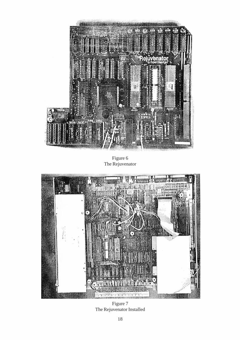
Figure 6The Rejuvenator
Figure 7The Rejuvenator Installed
18