theory of machine & vt odisha theory of machine 3 chapter-1 simple mechanism syllabus: 1.1 link,...
TRANSCRIPT
SCTE & VT ODISHA THEORY OF MACHINE
1
LEARNING MATERIAL
STATE COUNCIL FOR TECHNICAL EDUCATION &
VOCATIONAL TRAINING, ODISHA, BHUBANESWAR
THEORY OF
MACHINE
(For Diploma and Polytechnic students)
4TH SEMESTER

SCTE & VT ODISHA THEORY OF MACHINE
2
CONTENTS
Sl.No. Chapter Pages
1 Simple mechanism 3-32
2 Friction 33-94
3 Power Transmission 95-117
4 governors and Flywheel 118-143
5 Balancing of Machine 144-151
6 Vibration of machine
parts
152-161

SCTE & VT ODISHA THEORY OF MACHINE
3
Chapter-1
Simple Mechanism
Syllabus:
1.1 Link, kinematic chain, mechanism, machine
1.2 Inversion, four bar link mechanism and its inversion
1.3 Lower pair and higher pair
1.4 Cam and followers
1.1 Understand the subject of theory of machine
Introduction :-
· A machine is a device by means of which available energy can be
converted into derived form of useful work. It is the assembly of
resistant bodies or links whose relative motions are successfully
constrained so that available energy can be converted into useful
work. Machines are used to transmit both motion and force
OR

SCTE & VT ODISHA THEORY OF MACHINE
4
A machine is device which receives energy and transforms it into
some useful work.
Example: Lathe, Shaper, Scooter etc..
· Theory of machine is the branch of engineering which deals with the
relative motion and force between various machine elements.
Resistance body:
· A body is said to be resistant body if it is capable of transmitting the
required force with negligible deformation. These bodies are the
parts of the machines which are used for transmitting motion and
forces.
· A link need not necessary be a rigid body, but it must be a resistant
body.
Example: Springs, belts and oil used in hydraulic press are
not rigid links but they are resistant bodies.
· Structure is an assemblage of a number of resistant bodies having no
relative motion between them. Structures are meant for taking loads
Difference between machine and structure:
Machine
Structure
· There is relative motion between its members.
· It converts available energy into useful work.
· Members are meant to transmit motion and forces.
· Example : car, lathe etc..
· There is no relative motion between them.
· It does not convert the available energy into useful work.
· Members are meant to take up loads only.
· Example : bridge, frames, buildings etc..

SCTE & VT ODISHA THEORY OF MACHINE
5
Classification of theory of machine:
Theory of machine
Kinematics Dynamics
Statics Kinetics
Kinematic:
Kinematic of machines is that branch of theory of machines which
deals with the study of relative motion of parts of which the machines are
constituted, neglecting consideration of forces producing it.
Dynamics:
Dynamics of machine is that branch of theory of machines which
deals with study of forces acting on different parts of the machine.
Statics:
Statics deals with the study of forces acting on the various parts of
machines (assumed to be without mass), when they are at rest.
Kinetics:
Kinetics deals with the study of forces which are produced due to
inertia of moving parts of machines.
OR
Kinetics deals with the study of inertia forces which are produced by
the combined effect of the mass and the motions of the various parts.
Kinematics:
Kinematics of motion i.e. the relative motion of bodies without
consideration of the forces causing the motion.

SCTE & VT ODISHA THEORY OF MACHINE
6
Plane motion
Rectilinear/translatory curvilinear motion
(Straight line) (Curved path)
Kinematic link:
Reciprocating Steam Engine:
Each part of a machine, which moves relative to ssome other part, is
known as link or element.
Links in reciprocating engine
Link-1 : piston, piston rod and cross head
Link-2 : crank, crankshaft and flywheel
Link-3 : cylinder, engine frame and main bearings
Link should have two characters.
1. It should have relative motion.
2. It should be a resistant body.
Types of links :
1. Rigid link :
A rigid link is on which does not undergo any deformation
while transmitting motion.
Example : Deformation of a connecting rod, crank etc.. is not
appreciable.
SCTE & VT ODISHA THEORY OF MACHINE
7
2. Flexible link :
A flexible link in one which is partly deformed in a manner
not to affect the transmission of motion.
Example : belts, ropes, chains and wires
3. Fluid link :
A fluid link is one which is formed by having a fluid in a
reciprocal and the motion is transmitted through the fluid by
pressure or compression only as in the case of hydraulic
presses, jacks and brakes.
Kinetic pair:
The two links or elements of a machine, when in contact with each
other are said to form a pair.
When two elements or links are connected in such a way that their
relative motion is constrained they form a kinematic pair and the process of
connecting them is called pairing.
Three types of constrained motions :
1. Completely constrained motion
2. Incompletely constrained motion
3. Successfully constrained motion
1. Completely constrained motion :
When the motion between a pair is limited to a definite
direction irrespective of the direction of force applied, then
the motion is said to be a completely constrained motion.
Example : The piston and cylinder(in a steam engine) from a
pair and the motion of the piston is limited to a definite
direction.
2. Incomplete constrained motion :
when the motion between a pair can take place in more than
one direction, then the motion is called an incompletely
constrained. The change in the direction of impressed force
may after the direction of relative motion between the pair.

SCTE & VT ODISHA THEORY OF MACHINE
8
Example : circular shaft in a circular hole may rotate or slide.
3. Successfully constrained motion :
When the motion between the elements, forming a pair is
such that the constrained motion is not completed by itself,
but by some other means, then the motion is said to be
successfully constrained motion.
Example : shaft in a foot step bearing
The shaft may rotate in the bearing or it may move upwards.
But if the load is placed on the shaft to prevent axial upward
movement of the shaft, then the motion of the pair is
successfully constrained.
Kinematic pair classification:
1. According to the type of relative motion between the elements.
2. According to the type of contact between the elements.
3. According to the type of closure.
Kinematic pairs
Relative motion between Contact between the Types of closure
the element element
(i) sliding pair (i) lower pair (i) self closed pair
(ii) turning pair (ii) higher pair (ii) force-closed pair
(iii) rolling pair
(iv) screw pair
(v) spherical pair

SCTE & VT ODISHA THEORY OF MACHINE
9
Lower pair :
When the two elements of a pair have a surface contact while
relative motion takes place and the surface of one element slides over the
surface of the other, the pair formed is known as lower pair.
Example : sliding pair, turning pair, piston cross head, tailstock on
the leather bed, shaft revolting in a bearing, steering gear, universal joint.
The relative motion is purely sliding or turning.
Higher pair:
When the two elements of a pair have a line or point contact while in
motion, the pair so formed is known as a higher pair. The relative motion
being the combination of sliding and turning, thus it is complex.
Example : belt, rope and chain drives, gears, cam and follower, ball
and roller bearing.
Kinematics chain:
When kinematic pair are so coupled that the last link is joined to the
first link to transmit a definite completely unsuccessfully constrained
motion- it forms a kinematic chain.
If each link is assumed to form two parts, with two adjacent links,
then the rotation.
L = 2p – 4 -------(i)
J =
L – 2 -------(ii)
L à no. of links
p à no. of pairs
J à no. of joints
Both equation (i) & (ii) are applicable to kinematic chain with lower
pairs. Also applicable to kinematic chain with higher pairs. Higher pair is
equivalent to two lower pairs with an additional element or link.

SCTE & VT ODISHA THEORY OF MACHINE
10
Problem-1
L = 3
p = 3
j = 3
L = 2p – 4 L – 3 L – 2
ð 3 = 2* 3 – 4
ð 3 > 2
ð LHS > RHS
J =
L – 2 L – 1
ð 3 =
* 3 – 2
ð 3 > 2.5
As LHS > RHS, it is not a kinematic chain and hence number of
relative motion is possible. Such type of chain is called locked chain &
forms a liquid frame or structure.
Problem-2
l = 4
p = 4
j = 4
l = 2p – 4
ð 4 = 2* 4 – 4
ð 4 = 4
ð LHS = RHS
J =
L – 2
ð 4 =
* 4 – 2
ð 4 = 4
ð LHS = RHS

SCTE & VT ODISHA THEORY OF MACHINE
11
It is a kinematic chain as LHS = RHS also called as constrained
kinematic chain. Since link CD can move in a definite direction. It is
constrained.
Problem-3
L = 5
P = 5
J = 5
L = 2p – 4
ð 5 = 2* 5 – 4
3
ð 5< 6
ð LHS < RHS
J =
L – 2
ð 5 =
* 5 – 2
ð 5 < 5.5
ð LHS < RHS
So it is not a kinetic chain. This chain is called unconstrained chain. The
relative motion is not completely constrained. This type of chain is used
rarely.

SCTE & VT ODISHA THEORY OF MACHINE
12
Mechanism:
When one element or link of a kinematic chain is fixed, the
arrangement may be used for transmitting or transforming motion. It is
termed as mechanism.
Types of mechanism
Simple mechanism Compound mechanism
Simple mechanism:
Mechanism having four links.
Example: Coupling rod mechanism of a locomotive beam engine etc.
Compound mechanism:
Mechanism having more than four lines. It may be formed
combining two or more simple mechanism.
Inversion :
Different mechanisms can be obtained by fixing different links in a
kinematic chain. It is known as inversion of the original kinematic chain.
Suppose number of links of a kinematic chain = L
So L different mechanisms may be obtained by fixing each of the
lines in turn. Each mechanism is termed as inversion.
Types of kinematic chains(most important kinematic chain)
1. Four bar chain or quadric cycle chain
2. Single slider crank chain
3. Double slider crank chain
Four bar chain or Quadric cycle chain:
· The kinematic chain is a combination of four limks or four kinematic
pairs, such that the relative motion between the links or elements is
completely constrained.
· Four links A, B, C & D each of them form a turning pair.

SCTE & VT ODISHA THEORY OF MACHINE
13
Grashof’s law:
According to Grashof’s law for a four bar mechanism, the
sum of the shortest and longest link lengths should not be greater
than the sum of the remaining two link lengths if there is to be
continuous relative motion between the two links.
Inversions of four bar mechanism:
1. Beam engine
2. Coupling rod of a locomotives (Double crank
mechanism)
3. Watt’s indicator mechanism (Double lever
mechanism)
Link description:
· In a four bar chain the mechanism in which if no link
makes a complete revolution will not be useful.
· In four bar chain, one of the links in particular the
shortest link will make a complete revolution relative
to the other three links, if it satisfies the Grashof’s law.
Such a link is known as crank or driver (i.e. AB)
· Link BC which makes a partial rotation or oscillation
is known as lever or rocker or follower.
· The link CD which connects the crank and lever is
called connecting rod or coupler.
· The fixed link AB is known a frame of the mechanism.

SCTE & VT ODISHA THEORY OF MACHINE
14
Beam engine (Type of steam engine) :
Beam Engine
· Here, when the crank rotates about the fixed center A,
the lever oscillates about the fixed center D.
· The end E of CDE is connected to the piston which
reciprocates as a result.
Rotary motion ------> Reciprocating motion --------> To power steam ship
Coupling rod of a locomotive (Double crank mechanism):
· There AD = BC (Both crank) connected to the
respective wheels.
· CD is called connecting rod.
· AB is fixed to maintain constant centre to centre
distances between the wheels.
· This mechanism is meant for transmitting rotary
motion from one wheel to the other.
Coupling of a locomotive

SCTE & VT ODISHA THEORY OF MACHINE
15
Watt’s Indicator Mechanism:
Watt’s Indicator Mechanism
· Four links :
Link-1 : fixed, link-2 - (AC), link-3 - (CE), and
link – 4 (BDF)
· The displacement of the link BFD is directly
proportional to the pressure of gas or steam which acts
on the indicator _______.
· For small displacement of the mechanism, the tracing
point E traces out approximately a straight line.

SCTE & VT ODISHA THEORY OF MACHINE
16
Single Slider Crank Chain:
A single slider crank chain is a modification of the basic four bar
chain. It consists of one sliding pair and three turning pairs. It is, usually,
found in reciprocating motion and vice versa.
In a single slider crank chain, as shown in figure the links 1 and 2, 2
and 3, and links 3 and 4 from three turning pairs while the links 4 and 1
from a sliding pair.
The link 1 corresponds to the frame of the engine, which is fixed.
The link 2 corresponds to the crank ; links 3 corresponds to the connecting
rod and links 4 corresponds to cross-head. As the crank rotates, the cross-
head reciprocates in the guides and thus the piston reciprocates in the
cylinder.
Inversions of single slider crank chain
We have seen in the previous article that a single slider crank chain
is a four-link mechanism. We know that by fixing, in turn, different links in
a kinematic chain, an inversion is obtained and we can obtain as many
mechanisms as the links in a kinetic chain. It is thus obvious, that four
inversions of a single slider crank chain are possible. These inversions are
found in the following mechanisms.
1. pendulum pump or bull engine:
In this mechanism, the inversion is obtained by fixing the cylinder or
link 4 (i.e. sliding pair), as shown in figure. In this case, when the crank
(link 2) rotates, the connecting rod (link 3) oscillates about a pin pivoted to
the fixed link 4 at A and the piston attached to the piston rod (link 1)

SCTE & VT ODISHA THEORY OF MACHINE
17
reciprocates. The duplex pump which is used to supply feed water to boilers
have two pistons attached to link 1, as shown in figure.
2. Oscillating cylinder engine:
The arrangement of oscillating cylinder engine mechanism, as shown
in figure, is used to convert reciprocating motion into rotary motion. In this
mechanism, thye link 3 forming the turning pair is fixed. The link 3
corresponds to the connecting rod of a reciprocating steam engine
mechanism. When the crank (link 2) rotats, the piston attached to piston rod
(link 1) reciprocates and the cylinder (link 4) oscillates about a pin pivoted
to the fixed link at A.
3. rotary internal combustion engine or gnome engine:
Some time back, rotary internal combustion engines were used in
aviation. But now-a-days gas turbines are used in its place. It consists of
seven cylinders in one plane and all revolves about fixed centre D,as shown
in figure, while the crank (link 2) is fixed. In this mechanism, when the
connecting rod (link 4) rotates the piston (link 3) reciprocates inside the
cylinders forming link 1.

SCTE & VT ODISHA THEORY OF MACHINE
18
In this mechanism, the link AC (i.e. link 3) forming the turning pair
is fixed, as shown in figure. The link 3 corresponds to the connecting rod of
a reciprocating steam engine. The driving crank CB revolves with uniform
angular speed about the fixed centre C. A sliding block attached to the
crank pin at B slides along the slotted bar AP and thus causes AP to
oscillate about the pivoted A. A short link PR transmits the motion from AP
to the ram which carries the tool and reciprocates along the line of stroke
R1R2. The line of stroke of the ram (i.e. R1R2) is perpendicular to AC
produced.

SCTE & VT ODISHA THEORY OF MACHINE
19
In the extreme positions, AP1 and AP2 are tangential to the circle and
the cutting tool is at the end of stroke. The forward or cutting stroke occurs
when the crank rotates from the position CB2 to CB1 ( or through an angle
) in the clockwise direction.the return stroke occurs when the crank rotates
from the position CB2 to CB1 (or through angle ) in the clockwise
direction. Since the crank has uniform angular speed,therefore,
5. Whitworth quick return motion mechanism:
This mechanism is mostly used in shaping and slotting machines. In
this mechanism, the link CD(link 2) forming the turning pair is fixed, as
shown in figure. The link 2 corresponds to a crank in a reciprocating steam
engine. The driving crank CA (link 3) rotates at a uniform angular speed.
The slider (link 4) attached to the crank pin at A slides along the slotted bar
PA (link 1) which oscillates at a pivoted point D. the connecting rod PR
carries the ram at R to which a cutting tool is fixed. The motion of the tool
is constrained along the line RD produced, i.e. along a line passing through
D and perpendicular to CD.

SCTE & VT ODISHA THEORY OF MACHINE
20
When the driving crank CA moves from the position CA1 to CA2 (or
the link DP from the position DP1 to DP2) through an angle in the
clockwise direction, the tool moves from the left hand end of its stroke to
the right hand end through a distance 2 PD.
Now when the driving crank moves from the position CA2 to CA1
(or the link DP from DP2 to DP1) through an angle in the clockwise
direction, the tool moves back from right hand end of its stroke to the left
hand end.
A little consideration will show that the time taken during the left to
right movement of the ram(i.e. during forward or cutting stroke) will be
equal to the time taken by the driving crank to move from CA1 to CA2.
Similarly, the time taken during the right to left movement of the ram(or
during the idle or return stroke) will be equal to the time taken by the
driving crank to move from CA2 to CA1
Since the crank link CA rotates at uniform angular velocity therefore
time taken during the cutting stroke(or forward stroke) is more than the
time taken during the return stroke. In other words, the mean speed of the
ram during cutting stroke is less than the mean speed during the return
stroke. The ratio between the time taken during the cutting and return
strokes is given by

SCTE & VT ODISHA THEORY OF MACHINE
21
Example:
A crank and slotted lever mechanism used in a shaper has a centre
distance of 300 mm between the centre of oscillation of the slotted lever
and the centre of rotation of the crank. The radius of the crank is 120 mm.
Find the ratio of the time of cutting to the time of return stroke.
Solution:
Given: AC = 300 mm ; CB1 = 120 mm
The extreme positions of the crank are shown in figure. We know
that

SCTE & VT ODISHA THEORY OF MACHINE
22
Example:
In a crank and slotted lever quick return motion mechanism, the
distance between the fixed centres is 240 mm and the length of the driving
crank is 120 mm. Find the inclination of the slotted bar with the vertical in
the extreme position and time ratio of cutting stroke to the return stroke.
If the length of the slotted bar is 450 mm, find the length of the
stroke if the line of stroke passes through the extreme positions of the free
end of the lever.
Solution:
Given: AC = 240 mm ;
CB1 = 120 mm ;
AP1 = 450 mm
Inclination of the slotted bar with the vertical
Let ס 1= inclination of the slotted bar with the vertical.
The extreme position of the crank are shown in figure. We know that
=
= 2

SCTE & VT ODISHA THEORY OF MACHINE
23
Length of the stroke:
We know that length of the stroke,
R1R2 = P1P2 = 2P1Q = 2AP1 sin (900 -
= 2 ?
? G
Example:
Figure shows the layout of a quick return mechanism of the
oscillating link type, for a special purpose machine. The driving crank BC
is 30 mm long and time ratio of the working stroke to the return stroke is to
be if the length of the following stroke of R is 120 mm, determine the
dimensions of AC and AP.
Solution:

SCTE & VT ODISHA THEORY OF MACHINE
24
Given: BC = 30 mm ;
R1R2 = 120 mm ;
Example:
In a whitworth quick return motion mechanism, as shown in figure,
the distance between the fixed centres is 50 mm and the length of the
driving crank is 75 mm. The length of the slotted lever is 150 mm and the
length of the connecting rod is 135 mm. Find the ratio of the time of cutting
stroke to the time of return stroke and also the effective stroke.

SCTE & VT ODISHA THEORY OF MACHINE
25
Double slider crank chain:
A kinematic chain which consists of the turning pair and two sliding
pair is known as double slider crank chain, as shown in figure.we see that
the link 2 and link 1 form one turning pair and link 2 and link 3 from the
second turning pair. The link 3 and link 4 from one sliding pair and link 1
and link 4 from the second sliding pair.
Inversions of double slider crank chain:
The following three inversions of a double slider crank chain are
important from the subject point of view:
1. Elliptical trammels:
It is an instrument used for drawing ellipses. This inversion is
obtained by fixing the slotted plate (link 4), as shows in figure. The fixed
plate or link 4 has two straight grooves cut in it, at right angles to each
other. The link 1 and link 3, are known as sliders and from sliding pairs
with link 4. The link AB (link 2) is a bar which forms turning pairs with
links 1 and 3.
When the links 1 and 3 slide along their respective grooves, any
point on the link 2 such as P traces out an ellipse on the surface of link 4, as
shown in figure (a). A little consideration will show that AP and BP are

SCTE & VT ODISHA THEORY OF MACHINE
26
semi-major axis and semi-minor axis of the ellipse respectively. This can be
proved as follows:
Let us take OX and OY as horizontal and let the link BA is inclined
at an angle with the horizontal, as shown in figure (b). Now the co-
ordinates of the point P on the link BA will be
x = PQ = AP cos ; and y = PR = BP sin
or
?
squaring and adding,
This is the equation of an ellipse. Hence the path traced by point P is
an ellipse whose semi-major axis is AP and semi-minor axis is BP.
If P is the mid- point of link BA, then AP = BP. The above equation
can be written as
This is the equation of circle whose radious is AP. Hence if P is the
mid-point of link BA, it will trace a circle.

SCTE & VT ODISHA THEORY OF MACHINE
27
2. Scotch yoke mechanism:
This mechanism is used for converting rotary motion into a
reciprocating motion. The inversion is obtained by fixing either the link 1 or
link 3. In figure, link 1 is fixed. In this mechanism, when the link 2 (which
corresponds to crank) rotates about B as centre, the link 4(which
corresponds to a frame) reciprocates. The fixed link 1 guides the frame.
3. Oldham’s Coupling:
An Oldham’s coupling is used for connecting two parallel shafts
whose axes are at a small distance apart. The shafts are coupled in such a
way that if one shaft rotates, the other shaft also rotates at the same speed.
This inversion is obtained by fixing the link 2, as shows in figure (a). The
shafts to be connected have two flanges (link 1 and link 3) rigidly fastened
at their ends by forging.
The link 1 and link 3 from turning pairs with link 2. These flanges
have diametrical slots cut in their inner faces, as shown in figure. The
intermediate piece (link 4) which is a circular disc, have two tongues(i.e.
diametrical projections) T1 and T2 on each face at right angles to each other,

SCTE & VT ODISHA THEORY OF MACHINE
28
as shown in figure (c). the tongues on the link 4 closely fit into the slots in
the two flanges (link 1 and link 3). The link 4 can slide or reciprocate in the
slots in the flanges.
When the driving shaft A is rotated, the flange C (link 1) causes the
intermediate piece (link 4) to rotate at the same angle through which the
flange has rotated, and it further rotates the flange D (link 3) at the same
angle and thus the shaft B rotates. Hence link 1,3 and 4 have the same
angular velocity at instant. A little consideration will show, that there is a
sliding motion between the link 4 and each of the other link 1 and 3.
If the distance between the axes of the shafts is constant, the centre
of intermediate piece will describe a circle of diameter equal to the distance
between the axes of the two shafts. Therefore, the maximum sliding speed
of each tongue along its slot is equal to the peripheral velocity of the centre
of the disc along its circular path.
Let: = angular velocity of each shaft in rad/s, and
d = distance between the axes of the shafts in metres.
maximum sliding speed of each tongue (in m/s),
v = G

SCTE & VT ODISHA THEORY OF MACHINE
29
CAM AND FOLLOWERS:
Definition:
A cam may be defined as a rotating, oscillating or
reciprocating body which imparts a reciprocating or oscillating motion to
another body, called a follower.
The cam and the follower constitute a higher pair.
Application:
Used in clocks, printing machines, internal combustion
engines for operating valves, paper cutting machines, automatic screw
cutting machines, shoe making machinery, feed mechanism of automatic
lathe.
Classification of follower:
Follower
Surface in contact Motion of the follower Path of motion of the follower
(i) Knife edge follower (i) Reciprocating or (i) Radial follower
(ii) Roller follower translating follower (ii) Offset follower
(iii) Flat faced or (ii) Oscillating or
(iv) Spherical faced follower rotating follower
Manufacturing of cam :
A cam is difficult to manufacture especially when it is to be
produced in small quantities. When produced on a mass scale, it is
manufactured by a punch press, by die casting or by milling from the
master cam.
Knife edge follower :
· When the connecting end of the follower has a sharp knife
edge, it is called a knife edge follower.
· Seldom used.
· Small area of contacting results in excessive wear.

SCTE & VT ODISHA THEORY OF MACHINE
30
· A considerable side thrust exists between the follower and the
guide.
Roller follower :
· When the connecting end of the follower is a roller, it is
called a roller follower.
· Since rolling motion between the contact surfaces, the rate of
wear is greatly reduced.
· Also side thrust exist between the follower and the guide.
· Extensively used (where more space is available)
· Application – Stationary gas and oil engines, aircraft engines
Flat faced or mushroom follower :
Spherical faced follower :

SCTE & VT ODISHA THEORY OF MACHINE
31
Note:
When a flat faced follower is used in automobile engine, high
surface stresses are produced as to minimize these stresses, the flat end is
machined to a spherical shape.
Reciprocating or translating follower:
When the follower reciprocates in guides as the cam rotates
uniformly, it is known reciprocating follower.
Oscillating or rotating follower :
When the uniform rotary motion of the cam is connected into
predetermined oscillatory motion of the follower, it is called oscillating or
rotating follower.
Radial follower:
When the motion of the follower is along an axis passing through the
centre of the cam, it is known as radial follower.
Offset follower:
· When the motion of the follower is along an axis away from the axis.
If cam centre, it is called off-set follower.
· Off-set can be done by springs, gravity or hydraulic means.

SCTE & VT ODISHA THEORY OF MACHINE
32
Classification of cam :
Cams
Radial or Disc cam Cylindrical cam
Reciprocating cam Tangent cam Circular cam
Radial or Disc cam :
In radial or disc cam, the follower reciprocates or oscillates in a
direction perpendicular to the axis of cam rotation or perpendicular to the
cam shaft.
Cylindrical cam :
· In cylinder cam, the follower reciprocates or oscillates in a direction
perpendicular to the cam shaft.
· The follower rides in a groove at its cylindrical surfaces.

SCTE & VT ODISHA THEORY OF MACHINE
33
Chapter-2
Friction
Syllabus:
2.1 Revision of topic previously taught
2.2 Friction between nut and screw for square thread,
screw jack
2.3 Bearing and its classification, Description of roller,
needle roller & ball bearings.
2.4 Torque transmission in flat pivot & conical pivot
bearings.
2.5 Flat collar bearing of single and multiple types.
2.6 Torque transmission for single and multiple
clutches
2.7 Working of simple frictional brakes.
2.8 Working of Absorption type of dynamometer
DEFINITION:
When a body moves or tends to move on another body
(surface/block), there exists some resistance or opposing force in a direction
opposite to the direction of the movement of the body. This opposing force
is called force of friction or friction.
TYPES OF FRICTION:
i. Dry friction
ii. Rolling friction
iii. Skin friction
iv. Film friction

SCTE & VT ODISHA THEORY OF MACHINE
34
(i) Dry friction:
This type of friction takes place between two bodies having relative
sliding motion, when there is no intermediate fluid between their surfaces.
(ii) Rolling friction :
This type of friction occurs between two bodies directly in contact
when the relative motion between them is purely rolling as in case of roller
& ball bearing.
(iii) Skin friction :
When the two bodies between which the relative motion is separated
by a film or lubricant of infinitesimally small thickness then the friction is
called skin friction.
(iv) Film friction :
When the surfaces of two bodies are completely separated by a film
of lubricant then that friction is called film friction.
Laws of friction:
· When two bodies are in contact, the force of friction always acts in a
direction opposite to that in which the body moves or tends to move.
· The force of friction is dependent upon the type of material of the
bodies whose surfaces are in contact.
· The force of friction is independent of the area of contact between
the two surfaces.
· The force of friction is independent of the relative velocity of sliding
between the two surfaces.
· The force of frictions directly proportional to the normal reaction
between the surfaces in contact for a particular material in contact
for a particular material of which the bodies are made up.
F α N
ð F = µ N
Where µ = proportionality constant. i.e. also called as co-efficient of
friction.

SCTE & VT ODISHA THEORY OF MACHINE
35
Limiting Angle of Friction:
F = µ N
ð µ =
tan φ =
ð tan φ = µ
Liming angle of friction
W = weight of body
P = force acting on horizontal direction
N = normal reaction
· when the body just beings to slide the above forces will being
equilibrium.
· Limiting angle of friction is the angle (θ) at which the body tends to
or just starts to slide.
· The maximum force of friction which acts at this condition is
limiting force of friction.

SCTE & VT ODISHA THEORY OF MACHINE
36
Angle of repose :
F = w sinα
N = w cosα
F = µ N
ð F = µ Wcosα
ð Wsinα = µ Wcosα
ð Sin α = µ cosα
ð µ =
ð µ = tanα
ð tanφ = tanα
ð φ = α
· if the body is in equilibrium in inclined plane with angle α then the
angle of repose (α)in equal to the angle of friction (θ).
· If the angle of inclination (α) of the plane to the horizontal plane is
such that the body beings to move down the plane then the angle (α)
is called angle of repose.
Minimum force required to slide on a rough horizontal plane :
Here, P = Force acting on the body
W = Weight of the body
N = Normal reaction.
F = Frictional force

SCTE & VT ODISHA THEORY OF MACHINE
37
Let the P (force) acting on the body at an angle θ to the horizontal.
At equilibrium condition
Pcosθ = F -----------------(i)
N + Psinθ = W -----------(ii)
ð N = W – Psinθ
Pcosθ = µ × N
ð Pcosθ = µ (W – Psinθ)
ð Pcosθ = tanφ (W – Psinθ)
ð Pcosθ =
(W – Psinθ)
ð Pcosθ × Pcosφ = Wsinφ – Psinθ × sinφ
ð P(cosθ × cosφ + sinθ × sinφ) = Wsinφ
ð Pcos(θ - φ) = Wsinφ
ð P =
To minimum value of P then
Cos(θ – φ) = 1
ð Cos(θ – φ) = cos 0
ð (θ – φ) = 0
ð Θ = φ
Due to the maximum value domination then minimum value of
numerator or value of P
Pmin = Wsinφ

SCTE & VT ODISHA THEORY OF MACHINE
38
Question-1
A body resting on rough horizontal plane required a pull of 180N
inclined at 30° to the horizontal plane just to move, it was found that a push
of 220N inclined at 30° to the horizontal plane just move the body.
Determine the weight of body and co-efficient of friction.
`
Answer :
Here,
Case – 1
F = 180cos30°
W = N + 180sin 30°
µ N = 180cos30°
w = N + 90
ð N = 155.88/µ
ð W = 155/µ + 90 ---------------(i)
Case -2
F = 220cos30
ð F = 190.52
ð µ N = 190.52
W + 220sin30 = N
ð W = N – 110
ð N = 190.52/µ
ð W = 190.52/µ – 110 ------------(ii)

SCTE & VT ODISHA THEORY OF MACHINE
39
From equation-(i) & equation-(ii)
155.88/µ + 90 = 190.52/µ – 110
ð .
=
.
ð 90 µ + 110 µ = 190.52 – 155.88
ð µ = .
ð µ = 0.1732
put the value of µ in equation (ii)
W = 190.52/µ – 110
ð W = 190.52/0.1732 – 110
ð W = 990N
SCTE & VT ODISHA THEORY OF MACHINE
40
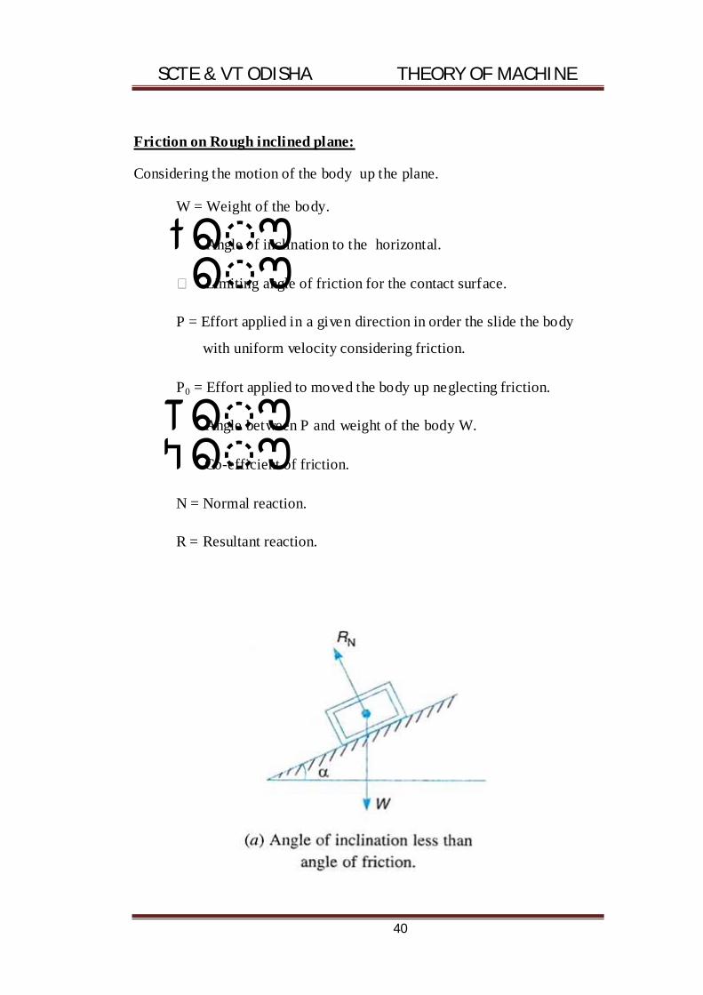
Friction on Rough inclined plane:
Considering the motion of the body up the plane.
W = Weight of the body.
Angle of inclination to the horizontal.
Limiting angle of friction for the contact surface.
P = Effort applied in a given direction in order the slide the body
with uniform velocity considering friction.
P0 = Effort applied to moved the body up neglecting friction.
Angle between P and weight of the body W.
Co-efficient of friction.
N = Normal reaction.
R = Resultant reaction.

SCTE & VT ODISHA THEORY OF MACHINE
41
Without friction:
Applying lami’s theorem

SCTE & VT ODISHA THEORY OF MACHINE
42
=
?
=
?
By considering friction:

SCTE & VT ODISHA THEORY OF MACHINE
43
{ ?Ø ?=
?θ ?+ Ø}
?
?Ø ? =
? ?θ ? Ø?
=
? ??θ ? Ø??
=
? ?θ α Ø??
?
?Ø ?=
[θ ?α Ø?]

SCTE & VT ODISHA THEORY OF MACHINE
44
Numerical problems:
Problem-1
An effort of 1500 N is required to just move a certain body upon
inclined plane of angle 12 with the horizontal, force acting parallel to the
plane. If the angle of inclination is increased to 15 then the effort required
is 1720 N find the weight of the body & co-efficient of friction.
Soplution:
G
W = 7500N.

SCTE & VT ODISHA THEORY OF MACHINE
45
σ = 0
1500 = F1 + 12
= 1 + 12
= wcos 12+ w sin 12
1500 = w (sin 12+ cos12)
1500 = w(0.207 + . 0.97 ).........................(1)
1720 = w( sin 15 + cos 15)
1720 = w (0.25 + . 0.96 )..............................(2)
Dividing equation -1 to equation -2, we get
1720/1500 = w (0.25 + . 0.96)/ w(0.207 + . 0.97 )
1500(0.25 + . 0.96) = 1720 (0.207 + . 0.97)
1440 + 388 = 356.4 + 1560.04
133.38 = 29.96
= 29.96/ 133.38 = 0.13112
So w = 4676.17N

SCTE & VT ODISHA THEORY OF MACHINE
46
Considering the motion of the body down the plane :-
Neglecting friction:-
( ) =
? (θ )?
=
(θ )
Considering friction:-
? ? ? Ø? =
? ??θ ? Ø??
? (? Ø)?=
? ??θ ? Ø??
�
( Ø) =
? ? ?θ (? Ø???
�
( Ø) =
?θ ( Ø)?
Efficiency of the inclined plane:-
? =
Let us consider the following two cases:
For the motion of the body up the plane:
? =
=
?? Ø? Ø
? Ø

SCTE & VT ODISHA THEORY OF MACHINE
47
=
?
( ? ) (Ø ? )
(Ø ?? Ø?)
= ?
( ? )×
(Ø ?? Ø?)
(Ø ? )
= ?
× ? ? × ×
. ?? Ø? ?? Ø?. ?
(Ø ? )
= ?
× ? ? × × (
. ?? Ø?
?Ø ? ?-
?? Ø?. ?
(Ø ? ))
= ?
× ? ? × × sin . cot (? +Ø)- cos
= ? × θ . ?? Ø?
. ? ? .
If θ = 90°
? = ?? Ø?
?
= ?
(? Ø)
If = 90 +?
? = ?? Ø? ? ? ?
? ( ? )
= ?? Ø? ?
? ?
= ? . ?
(? Ø)

SCTE & VT ODISHA THEORY OF MACHINE
48
For the motion of the body down the plane:
? =
=
?
?? Ø?
If = 900
? = ?
?? Ø? =
?
(? Ø)
= (? Ø)
?
If = 90 + ?
? = ? ( ? )
?? Ø? ? ? ?
= ? ?
?? Ø? ?
= (? Ø)
? × Ø

SCTE & VT ODISHA THEORY OF MACHINE
49
SCREW FRICTION:
Ø The fastening like screws, bolts, nuts etc have screw threads which
are made by cutting a continuous helical groove on a cylindrical
surface.
Ø If threads are cut on the outer surface of the solid rod, these are
known as outernal threads. & if the threads are cut on the internal
surface of a hollow rod then these are known as internal threads.
Helix:
Path traced by a thread while moving along a screw thread.
Pitch:
It is the distance from a point of a screw to a corresponding point on
the next thread, measured parallel to axis of the screw.
Lead:
Distance of a screw thread advanced axially in one turn
Lead = pitch (single thread)
Lead = n x pitch (multi thread)
Depth of thread:
Distance between top & bottom surfaces.
Or distance between crest & root.
Helix angle(ן ):-
tanן =
Where d = mean diameter.

SCTE & VT ODISHA THEORY OF MACHINE
50
Friction in screw and nut:- (up)
The motion of a nut on a screw is similar or analogous to the motion
on an inclined plane when the nut rises the motion is similar to up the plane
taking friction into consideration.
Mechanical advantage =
ן
ן ....................... (1)
From equation-1,
ן
ן
If ? o
ן
ן
= ן
ן
= cot (ן )
M.A = cot (ן )

SCTE & VT ODISHA THEORY OF MACHINE
51
Velocity ratio =
. = .
V.Rb = cot?
Mechanical efficiency = (? Ø)
?
Down:-
�
( Ø) =
?θ ( Ø)?.............................(1)
From equation-1
M.A = W/P
= ? ?? Ø??
?? Ø?
= 90°
?
=
? ?? Ø??
?? Ø?
= ?? Ø?
?? Ø?
= cot( ? - Ø)
h = (? Ø)
?

SCTE & VT ODISHA THEORY OF MACHINE
52
Torque required to lift the load by a screw jack:-
Up:
Along the plane:
p cosן = w sinן
. p cosן = w sinן G .........................(1)
Perpendicular to plane, N= w. cosן G ן ..................(2)
In place of ‘N’ put equation -2
P cosן ן ן ן
ן ן ן
ן � ן ן = ן
ן � G ן ן G ן
ן G ן ן G ן
ן
G ן ן
G ן
ן G G ן
= w (
ן G G ן
)
p.cos(ן ) = w. sin ן
p = G ן
ן

SCTE & VT ODISHA THEORY OF MACHINE
53
= . tan (? +Ø)
Torque, T = P×
Where P is the effort applied at the circumference of the screw it lift
the load if we rae applied load by leaver then T = P X l
V.R =
M.A =
=
(? Ø)
M.A = cot(? +Ø)
= .
. =
?? Ø?
= ?? Ø?.
Power = TW
= ×
,
= speed in rpm.
W = angular velocity.
Problem-2:
A screw jack has a thread of 10 mm pitch what effort applied at the
end of a handle having 400 mm long will be required to lift a load at of
2KN if the efficiency 45 %.
Solution:
given data:
Pitch (Pc) = 10 mm
Long (l) = 400mm

SCTE & VT ODISHA THEORY OF MACHINE
54
Weight (W) = 2KN
Efficiency = ( ) = 45% = 0.45
= ?? Ø?.
0.45 = ?? Ø?.
. .
�
?? Ø?. . . = 0.45
tan(? +Ø) = 8.84× 10
P = w. tan(? +Ø)
= 2× 10 × 8.84 × 10
= 17.68 N .
? effort applied at the end is 17.68 N.
Problem:
An electric motor driven power screw moves a nut in a horizontal
plane against a force of 75 KN at a speed of 300mm/min. The screw has a
single square thread of 6mm pitch of a diameter of 37mm. The co-efficient
of friction at the screw thread is 0.1 estimate the power of the motor.
Solution:
given data:
Load(w) = 75 KN =75× 10
Speed = 300mm/min
Pitch(Pc) = 6mm
Diameter (d) = 37mm
Co-efficient =0.1(tan )
N = 300/6 = 50 rpm

SCTE & VT ODISHA THEORY OF MACHINE
55
P = w. tan(? +Ø)
tan? =
.
p = . ? Ø
? . Ø = 11.43× 10
T = ×
= 11.43 × 10 ×
Power = Tw = T ×
= 1108
= 1.1 kw
Relation between load and effort when the load lifted up in a simple
screw jack:-
Up:
p = w. tan?? +Ø? … … … … … … … … . (1)
. = ×
P =
.................................(2)
From equation-1 and equation-2
= w.tan(? +Ø)
P1 = .
. tan (? +Ø)
P1 = .
?
? Ø
? . Ø?
= .
(
.
. .
)

SCTE & VT ODISHA THEORY OF MACHINE
56
�� � � .
(
. .
. . )
M.A =
=
.
(
. .
. . )
= w× ( . . )
. ( . . )
=
× (
. .
. . )
V.R = . .
= .
.
=
×(
. .
. . )
. .
= ? . . ?
? . . ?×
.
=
.
( . . )
( . . )

SCTE & VT ODISHA THEORY OF MACHINE
57
Relation between load & effort when load is morning down in a simple
screw jack:-
Down:
P = W tan( ) ............................... (i)
P1l = P X
P =
.......................................... (ii)
From equation (i) & (ii)
P1 =
P1 =
G
=
(
G
)
P1 =
( G
G )
M.A =

SCTE & VT ODISHA THEORY OF MACHINE
58
Problem:
A screwjack has a square threaded screw of 7.5cm mean diameter.
The angle of inclination of the thread is 3 & the is 0.6 it is operated by a
handle of 45cm long what pull must be exerted at the end of the handle to
(i) raise & (ii) lower down a load of 1000N.
Answer:
Given data:
D = 7.5 Cm tan Ø = 0.6
=30
Ø = tan ?0.6? = 30.96
µ =0.6
l = 45 cm
w = 1000 N.
(i) P1 =
{ ( + Ø)}
= × .
× {tan?3 + 30.96?}
= 561.24
(ii) P1 =
{ ( - Ø)}
= × .
× {tan?3 - 30.96?}
= ?- 44.23?
= 44.23

SCTE & VT ODISHA THEORY OF MACHINE
59
Problem:
A simple screw jack has a square threaded screw of mean diameter
9cm, the pitch is 10mm is 0.12 . it is operated by a handle of 60 cm long
to raise & lower down a load of 2000 KN. Find out the efficiency in both
the cases.
Answer:
Given data:
D = 9cm =0.9 mm
Pc = 10 mm
µ = 0.12
= 2000 = 2000 × 10
L = 60 cm = 6 mm
P1 =
(
.
. )
= 312724.32
= 312.72 KN
M.A =
=
.
= 6.39
V.R =
= ×
= 3.76
? = .
=
.
. = 1.7

SCTE & VT ODISHA THEORY OF MACHINE
60
Rolling friction:
Concept:
When a cylinder rolls over a flat surface, it makes a line contact
parallel to the axis of the cylinder, and when a sphere roll, over a flat
surface it makes a point contact there is no sliding at the point or line
contact there is no sliding at the point or line contact, so the above two are
example of pure rolling, but in actual practice, pure rolling never occurs as
there is always some resistance to the rolling.
The contact surface of the two bodies (sphere or cylinder and
surface) are always more or less deformed by thge redaction between them,
so that the ideal point or te line contact degenerates into an area of contact.
The harder the materials in contact, the lesser the deformation of contact
surface. Even the hardest materials have a deformation (may be small).
Bearings:
Bearing is a mechanical element that permits relative motion
between the two parts, such as the craft and the housing with minimum
friction, rolling contact bearings are called anti- friction bearings
Ball bearings:

SCTE & VT ODISHA THEORY OF MACHINE
61
· Inner race is moving
· Outer race is stationary
· Anti friction element i.e. ball/roller/needle
· Cage which separates the balls or rollers from each other
Function of bearings:
Ø The bearing ensures free rotation of the shaft or the angle with
minimum friction
Ø The bearing supports the shaft or the axle and holds it in the correct
position.
Ø The bearing takes up the forces that act on the shaft or the axle and
transmits them to the frame and foundation.
Applications: (rolling contact bearings)
Ø Machine tool spindles
Ø Automobile front or rear axles
Ø Gear boxes
Ø Small size electric motors
Ø Rope sleeves, crane hooks and hoisting drums
Applications: (sliding contact bearings)
Ø Cranck shaft bearing in diesel and petreol engines
Ø Steam and gas turbines.
Ø Concrete mixtures
Ø Rope conveyors

SCTE & VT ODISHA THEORY OF MACHINE
62
Pivot & collar friction :
The rotating shafts are quite frequently subjected to axial load
which is known as thrust. This axial load produces lateral motion of
the shaft along its axis which is not desirable. In order to prevent the
lateral motion of shaft one or more bearing surfaces called pivots &
collars are provided.
A bearing surface provided at the end of the shaft is known as
pivot & a collar is provided along with the length of the shaft with
bearing surface of revolution.
Pivot bearing is same foot step bearing.
EX: shaft of steam turbin, propeller shafts of ships.
During motion rudding velocity is V
Rate of ware PV Pr = constant rate of ware
prw pr = c
P = intensity of press on the bearing surface
R = radious of the bearing
= angular velocity of the shaft
Assumption:
The disof press is uniform.
The wear is uniform.

SCTE & VT ODISHA THEORY OF MACHINE
63
Pivot bearing:
(i) Flat pivot bearing.
(ii) Conical pivot bearing.
Flat pivot bearing:
By considering uniform pressure
W = load transmitted over the nearing surface.
R = radious of bearing surface
P = intensity of press (
)
Let a small ring at a radious of ‘r’ having its radious or thickness dr.
Area of small bearing surface ( ) 2 G
Frictional resistance = ?
= ?
= 2 G
Fr = ? 2 = 2 ? G

SCTE & VT ODISHA THEORY OF MACHINE
64
To reque on the ring Tr = Fr x r
= 2 µ ρr. dr × r
= 2 µ ρr. dr
T = ? 2 µ ρr
= 2 µ ρ ?
= 2 µ ρ
]
= 2 µ ρ R
=
T =
(3)
Power lost in friction:
P = Tw (4)
W =
N = speed in rpm.
P =
×
=
=
P =

SCTE & VT ODISHA THEORY OF MACHINE
65
Considering uniform wear:
Pr = constant
Pr = c
P= c/r
= × 2
W = ? × 2
= ?
× 2
=? 2 .
=2 ?
= 2
C =
Torque (Tr) = 2 .
T = ? 2 .
= ? 2
.
= ? 2 .
= 2 ? .
=
= .
.
T =

SCTE & VT ODISHA THEORY OF MACHINE
66
Problem:
A vertical shaft 150mm in diameter rotating at 100rpm rests on
a flat end footstep bearing the shaft carries a vertical load of 20 N.
Assuming estimate the power lost in friction.
Solution:
Given data:
D = 150mm = 0.5m.
R = 75mm
N = 100mm
W = 20n
0.05
P =
= G
= 523.54 watt (ans)
Conical pivot bearing:

SCTE & VT ODISHA THEORY OF MACHINE
67
W = load carried by a shaft supported by a conical pivot
bearing.
Pn = intensity of press normal to the cone.
= samiangle of the cone.
= co-efficiency of friction between the shaft & the bearing.
R = radious of the shaft.
Consider a small ring of radius ‘r’ & thickness ‘dr’.
Let dl is the length of the ring along the cone.
sin =
dl=
α
Dl = dr cosecα (i)
Area of the small ring
= 2 .
= 2 . cosecα .
Considering uniform pressure:
= h .
= × 2 . cosecα .
=
=
= .sin
= × 2 . cosecα .sin
= × 2 .
SCTE & VT ODISHA THEORY OF MACHINE
68
W= ?
= ? × 2 .
= × 2 ? .
= 2 [
]
= R
=
Friction resistance (Fr) = .
= . × 2 . cosecα
Fr = 2 .
Frictional torque acting on the ring
Tr = Fr x r
=2 . . ×
= 2 . .
Total frictional torque. T= ? 2
. .
= 2 . ? .
= 2 [
]
= 2 ×
… … … … … … … . . ( )
Substituting the value of ‘pn’ in equ (i)
T = 2 .
=
× ×
×

SCTE & VT ODISHA THEORY OF MACHINE
69
T =
T=
[? = ]
Considering uniform wear:
= normal intensity of pressure at a distar ‘r’ from the central axis.
R =c
= c/r
Load transmitted to the ring
= ×
= × 2 .
=
. 2 .
= 2 .
Total load transmitted to thge bearing
W= ?
= ? 2 .
=2 ? .
=2 [ ]
= 2 .
�C =
Fr = . ?
= . × 2 . .
Tr = Fr.r

SCTE & VT ODISHA THEORY OF MACHINE
70
= . × 2 . . .
= 2 .
Total frictional torque acting on the bearing
T=? 2 .
=? 2
.
= 2 . ? .
= 2 . [
]
.
�T = . R2 ------------------- (i)
Substituting the value of ‘c’ in equation (i)
T = . R2
= ×
× R2
T =
×
oR T =
× [? = ]

SCTE & VT ODISHA THEORY OF MACHINE
71
Problem:
A conical pivot supports a vertical shaft of 200mm diameter
subjected to a load of 30KN. The cone angle is 1200 & co-efficient of
friction is 0.025 find the power lost in friction when the speed is
140rpm, assuming
1. uniform pressure
2. Uniform wear
Solution:
Given data:
D = 200mm = 30KN
= 120 = 0.025
N = 140rpm.
Uniform pressure:
T=
=
× 0.025 × 30 × 100 × 120
= 57.73
P = Tw
= T×
= 57.73× × ×
= 846.36 watt
Uniform wear:
T =
× × ×

SCTE & VT ODISHA THEORY OF MACHINE
72
=
G
= 43.301
P = Tw
= T
= 43.301
= 634.82 watt
Flat collar bearing:
Collar bearing are also known as thrust bearings.
r1 = external radius of collar
r2 = internal radius of collar.

SCTE & VT ODISHA THEORY OF MACHINE
73
Considering uniform pressure:
P =
P =
{( ) ( ) }
Tr = Fr×
= ×
= × × 2 . .
= × × 2 .
T =? × × 2 .
= 2 ? .
= 2 [
]dr
=
=
(( ) - ( ) )
=
. . ×
{( ) ( ) }× {( ) - ( ) }
T=
[
]
Considering uniform wear:
Pr = constant =C
P1r1=P2r2=c
= × 2 . .
= 2 ? ?. .

SCTE & VT ODISHA THEORY OF MACHINE
74
= 2 . (? = )
W = ?
= ? 2 .
= 2 ?
= 2 ( - )
�c =
( )
Fr = .
Tr = Fr.r
= . .
= . 2 . .
=
T = ? 2 . . .
= 2 ? .
= 2 [
]
= 2
( )×
( )
T =
[( + )]
T = ( )
T = [?( )
= . ]

SCTE & VT ODISHA THEORY OF MACHINE
75
Problem:
A thrust shaft of a ship has 6 collars of 6000mm external
diameter & 300mm internal diameter.otal thurst from the propeller is
1000KN if the co-efficient of friction is 0.12 & speed of the friction at
the thrust block,assuming uniform pressure, uniform wear.
Ans: (1)P = 26.4KW (ii) P=25.45KW
Let n is the no. Of collar in muliticollar
? =
h
? =
× {( ) ( ) }
:
N = 6,
D1 = 600,
d2 = 300,
r1 = 300mm,
r2 = 150mm
W = 1000KN,
= 0.12, = 90 .
i) Uniform pressure:
T =
[
]
=
× 0.12 × 1000 × [
]
= 28000

SCTE & VT ODISHA THEORY OF MACHINE
76
P = TW = 28000× × ×
= 263893.78 watt
= 263.8 kW
ii) uniform wear:
T=
[ + ]
=
× 0.12 × 1000 × (300 + 150)
= 27000
P = TW=27000× × ×
= 254469.watt
= 254.4 Kw
Problem:
A shaft has a no. Of collars in triangle with it the external
diameter of the collars is 400mm & the shaft diameter is 250mm if the
intensity of pressure is 0.35n/nm2& the co-efficient of friction is 0.05
estimate.
i. he power observed when the shaft runs at 105rpm carrying a
load of 150Kn
ii. No.of collers required
Solution:
Given data:
D1 = 400mm,
r1 = 200mm = 0.2m
= 0.05

SCTE & VT ODISHA THEORY OF MACHINE
77
D2 = 250mm,
r2 =125mm
N =105rpm
W= 180KN
P=0.35N/mn2
T=
[
]
=
× 0.05 × 150 × 1000 [
. .
. . ]
= 1240.38N.m
P = × ×
×
= × ×
× 1240.38
= 13638.69w
=13.638 Kw
(ii) No. Of collars
? =
× {( ) ( ) }
= ×
. × ×( )
= 5.59 = 6

SCTE & VT ODISHA THEORY OF MACHINE
78
Friction clutches:
A friction cloth has it principal application in the transmission
of the power shafts and mechanics which must be started and stopped
frequency.
Single disc or plate clutch:
A single disc or plate clutch consists of a clutch plate whose
both sides are faced with a friction material.
Considering 2 frictional surfaces, maintained in contact by an
axial thrust W.
T = torque transmitted by the clutch.
P = intensity of axial pressure with which the contact surface
are held together.
R1&r2 = internal and external radius of friction faces.
co-efficient of friction.
Area of the ring G

SCTE & VT ODISHA THEORY OF MACHINE
79
By considering uniform pressure:
Normal or axial force on the ring
= G
Fr =
= G
= G
Tr = Fr
= G
T = G
= G
= [

SCTE & VT ODISHA THEORY OF MACHINE
80
=
×
(
)×
=
× [
]
Considering uniform wear:
Pr = c
? =
= × 2 .
Fr =
= × × 2 .
= 2 .
Tr = Fr.r
= 2 .
T = ? 2
? ?.
=
? ?? .
=
? ?? - ?
T = ? ?
T =
In case of two surface torque transmitted
T = n
Where n = 2
Pmax × rmin = C

SCTE & VT ODISHA THEORY OF MACHINE
81
Pmixxr2 = C
Pmix =
PminXrmax=C
Pminxr1=c
Pmin =
Pavr=
? ?
The uniform pressure theory gives a higher frictional torque
then the unform wear theory.
Therefore uniform wear should be consider unless otherwise if
not started.
Problem:
A single plate clotch, with both sides effective has outer respectively
the maxinternal pressure at any point in the contact surface is not to
exceed 0.1N/mm2 .if co-effrient of friction is 0.3. betermined the
power transmitted by a clutch at a speed of 2500rpm.
Ans: given data:
D1= 300mm,
r1=150mm
D2= 200mm, r2=100mm
n = 2,
Pmax= 0.1N/mm2

SCTE & VT ODISHA THEORY OF MACHINE
82
= 0.3
N = 2500rpm.
Pmax = c/rc2
c = pmax×r2
= 0.1× 100
=10
C =
? ?
? = 2 ? - ?
= 2× × 10(150 - 100)
= 3141.59N
T = n (
)
= 2× 0.3 × 3141.59(
)
= 235619.25N-mm
= 235.619N-m
Power = T
= 235.619×
= 23
= 61684.90 watt
= 61.68 KW. Ans

SCTE & VT ODISHA THEORY OF MACHINE
83
Multiple disc clutch:
T =
= (n1 + n2) - 1
in case of multiple disc clutch
= no. Of pair clutch
n1 = no. Of disc on the driving shaft
n2 = no. Of disc on the driven shaft
In a multi plate clutch, the no. Of frictional lining and the metal
plates is increased with increases the capacity of a clutch to transmit
torque. The above figure shows a simplified diagram of a multi plate clutch.
Thed friction rings are splendid on their outer circumference and
engaged with corresponding splines on the flyu wheel. There are free to
slide axialy. The friction material thus, rotates with fly wheel and the
engine shaft. The no. of friction rings depends upon the torque to be
transmitted.
The driven shaft also support disc on the splines which rotates with
the driven shaft and can slide axially. If the actuating force on the pedal is
removed, a spring presses the disc into contact with the friction rings and
the torque is transmitted between the engine shaft and the driven shaft.
If n is the total no. of plates both onn the driving and the driven
members, the no. of active surface will be n – 1.

SCTE & VT ODISHA THEORY OF MACHINE
84
Problem:
A multiplate disc clutch transmits 50kw of power at 1800rpm.
Co-efficient of friction for the friction surfaces is 0.1. Axial intensity
of presser is not to exceed 160kn/m2. The internal radius is 80mm & is
0.7times the internal radius. Find the no of plates needed to transmits
the required torque.
Solution:
Given data :
Power = 55kw = 55x103w
N = 1800rpm
= 0.1
Pmar =160KN/m2
=160x103N/m2
R2 = 80mm = 0.08mt
R2 = 0.7×
=
. =
.
. = 0.114
= 2 ? - ?
= 2 × × 160 ×103× 0.08 × (0.114 - 0.08)
= 2734.4N
= 2.73 KN
P =Tw
? =
= ×
.

SCTE & VT ODISHA THEORY OF MACHINE
85
Total torque 291.79 N.m.
One surface
T=
= 0.1× 2734.4 × ( . .
)
= 26.52 N.m.
=
= .
. = 11
No. Of plate = n + 1 = 12 ans.
Problem:
A single dry plate clutch transmits 75kw at 900rpm . The axial
pressur is limited to 0.07N/mm2 .If co-efficient of friction is 0.25 ,
find:
1. Mean radious & face width of the friction lining
Assuming
= 4
2. External &internal radius of the clutch plate.
Solution:
given data:
P = 7.5 Kw = 7.5×10³w
N = 900rpm.
Pmax = 0.07N/mm2
= 0.25
= 4

SCTE & VT ODISHA THEORY OF MACHINE
86
= 4
= 4
×
= 4
+ = 8 - 8
8 - 8 = +
8 - = + 8
7 - 9 = … … … … . ( )
7 = 9
=
P = T×
T =
=
. ×
=
. ×
× ×
= 79.57 .

SCTE & VT ODISHA THEORY OF MACHINE
87
Brake:
A brake is a device by means of which artificial frictional
resistance is applied to a moving m/c member, in order to retard or
stop the motion of a m/c.
(Depending upon the arrangement)
Barkes are classified as follows
1. Hybraulic brake
2. Electric brake
3. Mechanical brake
Single block or shoe brake:
P = force applied at the end of the lever.
Rn = normal force (pressing the brake block on the wheel).
R = radious of the wheel.
2 angle of contact of the black
Ft = tangential breaking force/frictional force.
co-efficient of friction.
TB = breaking torque.

SCTE & VT ODISHA THEORY OF MACHINE
88
Ft = n
TB = Ft
n
Case-1:
Considering Ft passes through the point ‘o’ taking moment about
the point ‘o’.
σ =0
P G
RN =
Ft= n
=
TB = Ft
=
TB =

SCTE & VT ODISHA THEORY OF MACHINE
89
Case-ii:
Ft passes through a distance below the point ‘o’.
σ =0
P Ft RN
= n N
= N(
RN =
Ft = N =
TB = Ft
TB =
Clockwise movement:

SCTE & VT ODISHA THEORY OF MACHINE
90
Taking the movement about the point’o’
P Ft RN
= n N
= N(
RN =
Ft = N
=
TB = Ft
TB =
Case-3:
Ft passes through a distance of ‘a’ above ‘o’
Clockwise:
Taking moment about the point ‘o’
P -Ft RN
= n N

SCTE & VT ODISHA THEORY OF MACHINE
91
= N(
RN =
Ft = N
=
TB = Ft
TB =
Anticlock wises:
P -Ft RN
= n N
= N(
RN =
Ft = N
=
TB = Ft =

SCTE & VT ODISHA THEORY OF MACHINE
92
Dynamometer:
Dynamometer is device by means of which the energy or work
down by a primemovercan be measured.it is a brake having additional
device to measure frictional resistance by aling the m/c to run at the
rated speed.
Dynamometer:
(i) Absortion dynamometer.
(i) pronybrake dynamometer
(ii) ropebrake dynamometer
(ii) transmission dynamometer
(i) belt transmission
(ii) epicyclic dynamometer
(iii) torsion dynamometer.
Prong brake dynamometer:
W= weight at the outer end of the lever in N.
L=distance between the centre of the pulley to the weight w.
F = frictional resistance between the blocks & the pulley in N.

SCTE & VT ODISHA THEORY OF MACHINE
93
R = radius of the pulley in mt.
N = speed of the shaft in R.P.M.
Moment of the frictional resistance or torque on the shaft
T = F.R = W× N.M
Work down/min = T × 2
Power =
watt.
Rope Brake Dynamometre
It is another form of absorption type dynamometer which is most
commonly used for measuring the brake power of the engine. It consist of
one, two or more ropes wound around the flywheel or rim of a pulley fixed
rigidly to the shaft of an engine. The upper end of the ropes is attached to a
spring balance while the lower end of the ropes is kept in position by
applying a bead weight as shown in figure in order to prevent the slipping
of the rope over the flywheel, wooden blocks are placed at intervals around
the circumference of the flywheel.
In the operation of the brake, the engine is made to run at a
constant speed. The frictional torque, due to the rope, must be equal to the
torque being transmitted by the engine.
Let: W = dead load in newtons,
S = spring balance reading in newtons,
D = diameter of the wheel in metres,
d = diameter of rope in metres, and
N = speed of the engine shaft in r.p.m.
? load on the brake
= (W - S)N
We know that distance moved in one revolution
= (D + d)

SCTE & VT ODISHA THEORY OF MACHINE
94

SCTE & VT ODISHA THEORY OF MACHINE
95
Chapter-3
Power Transmission
Syllabus:
3.1 Concept of power transmission
3.2 Type of drives, belt, gear and chain drive.
3.3 Computation of velocity ratio, length of belts
(open & cross) with and without slip.
3.4 Ratio of belt tensions, centrifugal tension and
initial tension.
3.5 Power transmitted by the belt.
3.6 V-belts and V-belts pulleys.
3.7 Concept of crowning of pulleys.
3.8 Gear drives and its terminology.
3.9 Gear trains, working principle of simple,
compound, reverted and epicyclic gear trains.
SCTE & VT ODISHA THEORY OF MACHINE
96
Power transmission:-
Depending upon the shapes, cross-section 3 types
1. Flat belt
2. V-belt
3. Circular belt
Depending upon the amount of power transmission
1. Light
2. Medium
3. Heavy
Velocity ratio of open belt drive:-
It is the ratio between the velocities of the driver and the follower or
the driven.
Let d1 = diameter of the driver
d2 = diameter of the follower
N1= speed of the driver in r.p.m
N2 = speed of the follower in r.p.m
Length of the belt that passes over the driver in 1 minute
= length/min
= 1 1
Length of the belt that passes over the follower in 1 minute
= length/min = 2 2

SCTE & VT ODISHA THEORY OF MACHINE
97
Since length of the belt passes over the driver in 1 minute = length of
the belt passes over the driven in 1 mm.
So
( t is not consider)
If it is consider, V.R =
=
Peripheral velocity of the belt on the driving pulley:-
V1 =
? V2 =
If there is no slip, then V1 = V2
Velocity ratio of compound belt drive:-
N2/N1 = D1/D2 , N3/N2 = D2/D3

SCTE & VT ODISHA THEORY OF MACHINE
98
Slip of belts:-
Sometimes the frictional grips between the belts and shafts becomes
in sufficient which may cause some forward motion of the driver without
carrying the belt or forward motion of the belt without carrying the driven
pulleys or follower pulley with it. This is called slip of belt and is expressed
in percentage
Let S1% = slip between the driver and the belt
S2%= slip between the belt and the follower
Velocity of belt passing over the driver/sec
V =
-
×
V =
(1 -
) ............................(1)
Velocity of belt passing over the follower/sec
= V - V×
= V?1 -
?
=
(1 -
) ?1 -
?
=
?1 -
-
+
.
× ?
=
?1 -
?
=
?1 -
?
Where S = S1+S2( total % in slip)
D2.N2 = D1.N1?1 -
?
?
=
(1 -
)
“t” consider, ?
=
(1 -
)
SCTE & VT ODISHA THEORY OF MACHINE
99
Tension of an open belt drive:-
r1 and r2 = radius of the larger and smaller pulley
x = distance between centres of pulley that is o1 and o2
L = total length of the belt
O2M parallel to EF and O2M perpendicular to O1E
L = arc GJE = EF + arc FKH +HG
= 2× arc GJ +2EF+2 arcFK........................(1)
In triangle o , o2M
sin? =
.
=
? =
… … … … … … … ?2?
= 1 ?
+? ? ...............(3)
Arc FK = 2 ?
- ? ? ....................(4)
EF = O2M
O2M = ? ? 1 2? - ( 1 )
EF = O2 M = ? - ( - )
= x. ? 1 - ?
?
= x. ?1 -
?
?
+ ? . ? ( binomial expansion)
EF = x – ( )
.........................(5)
L = 2 (Arc GJ + EF+ Arc FK)

SCTE & VT ODISHA THEORY OF MACHINE
100
= 2
ן –
ן
When ן is very very small and as in radian. So, ן ן ן
L = 2
ן –
ן
= 2.
ן –
= 2.
–
So ,L =
Cross belt drive:-
L = arc GJE + EF+ arc FKH +HG
= 2.arc GJ +2 EF+2 arc FK
= 2(arc GJ + EF+ arc FK)
In triangle O1 O2 M , sinן
=
ן .................(1)

SCTE & VT ODISHA THEORY OF MACHINE
101
ן ...............(2)
Arc FK =
ן ....................(3)
EF = O2M
O2M =
EF = O2 M =
= x.
= x.
G ( binomial expansion)
EF = x –
L = 2. (arc GJ + EF+ arc FK)
L =
RATIO OF DRIVING TENSION FOR FLAT BELT DRIVE :-
T1 = tension in the belt on the tight side
T2 = tension in the belt on the slack side
= angle of contact in radian

SCTE & VT ODISHA THEORY OF MACHINE
102
Let PQ is in equilibrium under the forces T at P. Tension at
Q.(T+ T). Frictional force,F = RN
Where RN = normal reaction
= co-efficient of friction
σ =0
RN = T sin
+ ? + ?.
Since is very small , so
is very very small
So RN = T. ..........................(1)
σ = 0
F+ T.cos
= ? + ?.
F + T = +
F = + – T
F = RN =
� × . =
?
= ? .
log
=
=
Centrifugal tension:-
Since the belt continuously runs over the pulleys, therefore some
centrifugal force is passed whose effect is to increased the tension on both
tight and slack sides. The tension caused by centrifugal force is called
centrifugal tension.

SCTE & VT ODISHA THEORY OF MACHINE
103
Considering small portion PQ of the belt having contact angle d .
m = mass of the belt per unit length in kg.
v = linear velocity of the belt per unit in metre per second.
R = radius of the pulley over which the belt runs in metre.
TC = centrifugal tension acting tangentially at P and Q in newton
Length of PQ = r. d .
Mass of length PQ = mr d
Centrifugal force acting on PQ = Fc = mr d
Fc = m d ....................(1)
σ =0
TC.sin
+ TC.sin
= Fc
As
is very small . so sin
=
TC.sin
+ TC.sin
= Fc
2. TC
= m d
TC = m.v2

SCTE & VT ODISHA THEORY OF MACHINE
104
We know from ratio of tension that , 2.3 log
=
2.3 log
=
Maximum tension in the belt:-
1. Tc is neglected. Maximum tension T1 = bt
Where = maximum safe stress in newton per metre2
b= width of belt in mm
t= thickness of the belt in mm
2. Tc is consider
= +
= bt +
Power transmission by the belt:-
1. Tc neglected
P = ( - )V watt
2. Tc consider
P =?( - ) - ( - )?
P = ( - )V watt.
Or , P= ( - )V watt
Initial tension in the belt (To):-
When the pulleys are stationary, the belt is subjected to some tension as the
ends are joined together to make the belt continuously moved over the
pulleys . the tension is called initial tension.
To= initial tension in the belt
T1 = tension in the tight side of the belt
T2 = tension in the slack side of the belt
SCTE & VT ODISHA THEORY OF MACHINE
105
? = co-efficient of increase or decrease of the belt length per unit force.
Increase of tension in the tight side = T1-T0
Increase of length of the belt in the tight side = ? ( - )
Similarly decrease in tension in the slack side = -
Decrease in the length of the belt on the slack side = ? ( - )
Assuming the belt is perfectly elastic such that the length of the belt remain
constant. Therefore increase in length on the tight side is equal to decrease
in length on the slack side.
Mathematically , ? ? - ?= ? ( - )
T1-T0 = -
2 T0 = T1+T2
T0 =
if Tc is neglected.
If Tc is consider, TO = .
Width of belt:-
Ø At moderate speed the tension in a belt = T1
Ø At high speed , taking the centrifugal tension into account, the
maximum tension in a belt = Tmax
Ø To avoid excessive bending stress and to ensure adequate life, the
thickness of belt is fixed.
Ø For soft materials
= 25
Ø For normal belt
=35
Ø For stiff belt =
= 50

SCTE & VT ODISHA THEORY OF MACHINE
106
Problem:
In a flat belt drive the initial tension is 2000N. Co-efficient of
friction between the belt and pulley is 0.3 and the angle of lap on the
smaller pulley is 150. The smaller pulley has radius of 200 mm and rotates
at 500 r.p.m. find the power in KW transmitted by the belt.
Answer:
Given data
To = 2000N
= 0.3
= 150° = 2.61 radian
= 200mm
d2 = 400mm= 0.4m
N2 = 500 r.p.m
V=
=
. . .
= 10.47m/s
TO =(T1+T2)/2
�2000 = ( T1+T2)/2
�T1+T2 = 4000..................(1)
2.3 log
=
�log
=
. × .
. = 0.3404
�
= . =1.4
T1 = 1.4T2
T1+T2 = 4000
�1.4 T2+ T2 = 4000

SCTE & VT ODISHA THEORY OF MACHINE
107
�2.4 T2 = 4000
T2 = 4000/2.4= 1666.66
T1 = 1.4 T2
= 1.4 G = 2333.33
V-belts and V-belts pulleys:
We have already discussed that a V-belt is mostly used in factories
and workshops where a great amount of power is to be transmitted from one
pulley to another when the two pulleys are very near to each other.
The v-belts are made of frabic and cords moulded in rubber and
covered with fabric and rubber, as shown in figure. These belts are moulded
to a trapezoidal shape and aremade endless. These are particularly suitable
for short drives when the shafts are at a short distance apart. The included
angle for the V-belt is usually from 300-400. In case of falt belt drive, the
belt runs over the pulleys whereas in case of V- belt drive, the rim of the
pulley is grooved in which the V-belt runs. The effect of the groove is to
increase the frictional grip of the V-belt on the pulley and thus to reduce the
tendency of slipping. In order to have a good grip on the pulley, the V-belt
is in cotact with the side faces of the groove and not at the bottom. The
power is transmitted by the wedging action between the belt and the V-
groove in the pulley.

SCTE & VT ODISHA THEORY OF MACHINE
108
A clearance must be provided at the bottom of the groove, as shown
in figure in order to prevent touching to the bottom as it becomes narrower
from wear. The V-belt drive, may be inclined at any angle with tight side
either at top or bottom. In order to increase the power output, several V-belt
may be operated side by side. It may be noted that in multiple V-belt drive,
all the belts should stretch at the same rate so that the load is equally
divided between them. When one of the set of belts break, the entire set
should be replaced at the same time. If only one belt is replaced, the new
unworm and unstressed belt will be more tightly stetched and will move
difference velocity.
3.7 Concept of crowning of pulleys.
As mentioned is section 9.2, the rim of the pulley of a flat-belt drive
is slightly crowned to prevent the slipping off belt from the pulley. The
crowing can be in the from of conical surface or a convex surface.
Assume that somehow a belt comes over the conical portion of the
pulley and takes the position as shown in figure, its centre line remains in a
plane, the belt will touch the rim surface at its one edge only. This is
impractical. Owing to the pull, the belt always tends to stick to the rim
surface. The belt also has a lateral stiffness. Thus, a belt has to bend in the
way shown in figure.
Let the belt travel in the direction of the arrow. As the belt touches
the cone, the point a on it tends to adhere to the cone surface due to pull on
the belt. This means as the pulley will take a quarter turn, the point a on the
belt will be carried to b which is towards the mid-plane of the pulley than
that previously occupied by the edge of the belt. But again, the belt cannot

SCTE & VT ODISHA THEORY OF MACHINE
109
be stable on the pulley in the upright position and has to bend to stick to the
cone surface, it will occupy the position shown by dotted lines.
Thus, if a pulley is made up of two equal cones or of convex syrface,
the belt will tend to climd on the slopes and will thus, run with its centre
line on the mid-plane of the pulley.
The amount of crowing is usually 1/96 of the pulley face width.
Terms used in gears:
the folloing terms, which will be mostly used in this chapter, should
be clearly understood at the stage. These terms are illustrated in figure.
1. Pitch circle:
It is an imaginary circle which by pure rolling action, would
give the same motion as the actual gear.
A straight line may also be defined as a wheel of infinite
radius.
2. Pitch circle diameter:
It is the diameter of the pitch circle. The size of the gear is
usually specified by the pitch circle diameter. It is also known
as pitch diameter.

SCTE & VT ODISHA THEORY OF MACHINE
110
3. Pitch point:
It is common point of contact between two pitch circles.
4. Pitch surface:
It is the surface of the rolling discs which the meshing gears
have replaced at the pitch circle.
5. Pressure angle or angle of obliquity:
It is the angle between the common normal to two gear teethg
at the point of contact and the common tangent at the pitch
point. It is usually denoted by Ø.the standard pressure angles
are 14
and 200.
6. Addendum:
It is the radial distance of a tooth from the pitch circle to the
top of the tooth.
7. Dedendum:
It is the radial distance of the tooth from the pitch circle to the
bottom of the teeth.
8. Addendum circle:
it is the circle drawn through the top of the teeth and id
concentric with the pitch circle.
9. Dependum circle:
it is the circle drawn through the bottom of the teeth. It is also
called not circle.
Circular pitch:-
It is the distance measured on the circumference of the pitch circle from a
point of one tooth to the corresponding point on the next tooth. It is denoted
as Pc.
Pc =
d = diameter of the pitch circle
T = no. Of teeth on the gear.
When the two gears will be in mesh Pc should be same for both.

SCTE & VT ODISHA THEORY OF MACHINE
111
Pc =
=
=
DIAMETRAL PITCH:-
It is the ratio of no. Of teeth to the pitch circle diameter in mm. It is denoted
by Pd. Pd = T/D =
Module:-
It is the ratio of pitch circle diameter in mm to the no. Of teeth. It is denoted
as “m”.
M =
Question:
The no. Of teeth on each of two equal gear in mesh are 40. If the
module is 6 mm. Find pitch circle diameter, circular pitch, diametral pitch.
Ans:- given data:- T = 40
m= 6 m
Pd=
Pd = 1/6
Pd = T/D
=
? D = 240 mm
Pc =
=
×
= 18.84

SCTE & VT ODISHA THEORY OF MACHINE
112
Gear train:-
When two or more gear are made to mesh with each other to transmit
power from one shaft to another , such a combination is called gear train.
Different types of gear train:-
1. simple gear train
When there is only one gear on each shaft, as shown in figure. It is
known as simple gear train. The gears are represented by their pitch
circles.
When the distance between the two shafts is small, the two gears 1
and 2 are made to mesh with each other to transmit motion from one shaft
to the other, as shown in figure. Since the gear 1 drives the gear 2.
Therefore gear 1 is called the driver and the gear 2 is called the driven or
follower. It may be noted that the motion of the driven gear is opposite to
the motion of driving gear.
Let: N1 = speed of gear 1 (or driver) in r.p.m.,
N2= speed of gear 2 (or driven or follower) in r.p.m.,
T1= number of teeth on gear 1, and
T2= number of teeth on gear 2.
Since the speed ratio (or velocity ratio) of gear train is the ratio of
the speed of the driver to the speed of the driven or follower and ratio of
speed of any pair of gears in mesh is the inverse of their number of teeth,
therefore
Speed ratio =

SCTE & VT ODISHA THEORY OF MACHINE
113
2. Compound gear train
When there are more then one gear on a shaft, as shown in figure. It
is called a compound train of gear.
We have seen in art. That the ideal gears, in a simple train of gears
do not effect the speed ratio of the system. But these gears are useful in
bridging over the space between the driver and the driven.
But whenever the distance between the driver and the driven or
follower has to be bridged over by intermediate gears and at the same time
a great (or much less) speed ratio is required, then the advantage of
intermediate gears is intensified by providing compound gears on
intermediate shafts. In this case, each intermediate shaft has two gears
rigidly fixed to it so that they may have the same speed. One of these two
gears meshes with the driver and the other with the driven or follower
attached to the next shaft as shown in figure.
In a compound train of gears, as shown in figure, the gear 1 is the
driving gear mounted on shaft A, gears 2 and 3 are compound gears which
are mounted on shaft B. The gears 4 and 5 are also compound gears which
are mounted on shaft C and the gear 6 is the driven gear mounted on shaft
D.

SCTE & VT ODISHA THEORY OF MACHINE
114
Let: N1 = speed of driving gear 1,
T1= number of teeth on driving gear 1,
N2,N3,.......,N6 = speed of respective gears in r.p.m.,
and T2 ,T3.......,T6 = number of teeth on respective gears.
Since gear 1 is in mesh with gear 2, therefore its speed ratio is
=
Similarly, for gears 3 and 4, speed ratio is
=
And for gears 5 and 6, speed ratio is
=
The speed ratio of compound gear train is obtained by multiplying the
equations (1), (ii) and (iii),
?
×
×
=
×
×
=
× ×
× ×
3. Epicyclic gear train
We have already discussed that in an epicyclic gear train, the axes of
the shafts, over which the gears are mounted, may move relative to a fixed
axis. A simple epicyclic gear train is shown in figure, where a gear A and
the arm C have common axis at O1 about which they can rotate. The gear B
meshes with gear A and has its axis on the arm at O2, about which the gear
B can rotate.

SCTE & VT ODISHA THEORY OF MACHINE
115
We know that speed ratio = ?
=
Also
...(NB = Nc,being on the same
shaft)
For
and
to be same, each speed ratio should be ξ so that
ξ ξ
Arm is fixed. The gear train is simple and gear A can drive gear B or
vice-versa, but if gear A is fixed and the arm is rotated about the axis of
gear A(i.e. O1), then the gear B is forced to rotate upon and around gear A.
Such a motion is called epicyclic and the gear train arranged in such a
manner that one or more of their member move upon and around another
member is known as epicyclic gear trains (epi. Means upon and cyclic
means around). The epicyclic gear trains may be simple or compound.
The epicyclic gear trains are useful for transmitting high velocity
ratios with gears of moderate size in a comparatively lesser space.
Differential gears trains are used in the back gear of lathe, differential gears
of the automobiles, hoists, pulley blocks, wrist watches etc.

SCTE & VT ODISHA THEORY OF MACHINE
116
4. Reverted gear train
When the axes of the first gear (i.e. first driver) and the last gear (i.e.
last driven or follower) are co-axial, then the gear train is known as
reverted gear train as shown in figure.
We see that gear 1 (i.e. first driver) drives the gear 2(i.e. first driven
or follower) in the opposite direction, since the gears 2 and 3 are mounted
on the same shaft, therefore they form a compound gear and the gear 3 will
rotate in the same direction as that of gear 2. The gear 3(which is now the
second driver) drives the gear 4(i.e. the last driven or follower) in the same
direction as that of gear 1. Thus we see that in a reverted gear train, the
motion of the first gear and the last gear is like.
Let: T1= number of teeth on gear 1,
r1= pitch circle radius of gear 1, and
N1= speed of gear 1 in r.p.m.
Similarly,
T2 , T3 ,T4 = number of teeth on respective gears,
r2 , r3 , r4 = pitch circle radii of respective gears, and
N2, N3, N4 = speed of respective gears in r.p.m.

SCTE & VT ODISHA THEORY OF MACHINE
117
Since the distance between the centre of the shafts of gears 1and 2 as
well as gear 3 and 4 is same, therefore
r1 + r2 = r3 + r4
Also, thye circular pitch or module of all the gear is assumed to be
same, therefore number of teeth on each gear is directly proportional to its
circumference or radius.
? T1 + T2 = T3 + T4
And speed ratio =
Or
=
×
×

SCTE & VT ODISHA THEORY OF MACHINE
118
Chapter-4
Governors and Flywheel
Syllabus:
4.1 Function of governor
4.2 Classification of governor
4.3 Working of Watt, Porter, Proel and Hartnel governors.
4.4 Conceptual explanation of sensitivity, stability and
isochronisms.
4.5 Function of flywheel.
4.6 Comparison between flywheel & governor.
4.7 Fluctuation of energy and coefficient of fluctuation of
speed.
4.1 Function of governor: The function of a governer is to regulate the main speed of an engine
whem there are variations in the load e.g. when the load on an engine
increases, its speed decreases therefore it becomes necessary to increases
the supply working fluid.
In the other hand, when the load on the engine decreases its speed
increases and thus less working fluid is required. The governer
automaticallycontrol the supply of working fluid top the engine with the
varying load conditions and keep the mean speed within certain limits.

SCTE & VT ODISHA THEORY OF MACHINE
119
4.2 Classification of governor:
The governors may be classified as
1. Centrifugal governor
2. Inertia governor

SCTE & VT ODISHA THEORY OF MACHINE
120
4.3 Working of Watt, Porter, Proell and Hartnell governors.
Watt governors: The simplest form of a centrifugal governor is a watt governor, as
shown in fig it is basically a conical pendulum with links attached to a
sleeve of negligible mass. The arms of the governor may be connected to
the spindle in the following three ways:
1. The pivot P, may be on the spindle axis as shown in fig.
2. The pivot P, may be offset from the spindle axis and the arms when
produced intersect at O, as shown in fig.
3. The pivot P, may be offset, but the arms cross the axis at O, as
shown in figure.
Let
m = Mass of the ball in kg,
w = weight of the ball in newtons = m.g,
T = tension in the arm in newtons,
angular velocity of the arm and ball about the spindle axis in
rad/s,
r = radius of the path of rotation of the ball i.e. horizontal distance
from the centre of the ball to the spindle axis in metres,
Fc = centrifugal force acting on the ball in newtons = m. 2.r, and
h = Height of the governor in metres.

SCTE & VT ODISHA THEORY OF MACHINE
121

SCTE & VT ODISHA THEORY OF MACHINE
122
Porter governor: The porter governor is a modification of a watt’s governor. With
central load attached to the sleeve as shown in figure the load moves up and
down the central spindle. This additional downward force increases the
speed of revolution required to enable the balls to rise to any predetermined
level.
Let
m = mass of each ball in kg,
w = weight of each ball in newtons = m.g,
M = mass of the central load in kg,
W = weight of the central load in newtons = M.g,
R = radius of rotation in metres,

SCTE & VT ODISHA THEORY OF MACHINE
123

SCTE & VT ODISHA THEORY OF MACHINE
124

SCTE & VT ODISHA THEORY OF MACHINE
125
Example: A porter governor has equal arms each 250 mm long and pivoted on
the axis of rotation. Each ball has a mass of 5 kg and the mass of 5 kg and
the mass of the central load on the sleeve is 15 kg. the radius of rotation of
the ball is 150 mm when the governor begins to lift and 200 mm when the
governor is at maximum speed. Find the minimum and maximum speeds
and range of speed of the governor.
Solution:
Given:
BP = BD = 250mm = 0.25m
Mass m = 15kg
r1 = 150mm = 0.15m
r2 = 200mm = 0.2m

SCTE & VT ODISHA THEORY OF MACHINE
126
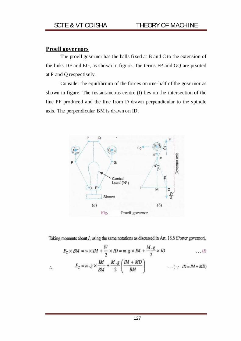
SCTE & VT ODISHA THEORY OF MACHINE
127
Proell governors The proell governer has the balls fixed at B and C to the extension of
the links DF and EG, as shown in figure. The terms FP and GQ are pivoted
at P and Q respectively.
Consider the equilibrium of the forces on one-half of the governor as
shown in figure. The instantaneous centre (I) lies on the intersection of the
line PF produced and the line from D drawn perpendicular to the spindle
axis. The perpendicular BM is drawn on ID.

SCTE & VT ODISHA THEORY OF MACHINE
128
Example:
A proell governor has equal arms of length 300 mm. the upper and
lower ends of the arms are pivoted on the axis of the governor. The
extension arms of the lower links are each 80 mm long and parallel to the
axis when the radii of rotation of the balls are 150 mm and 200 mm. the
mass of each ball is 10 kg and the mass of the central load is 100 kg.
Determine the range of speed of the governor.
Solution:
Given:
PF = DF = 300 mm;
BF = 80 mm ;
r1= 150 mm;
r2 = 200 mm;
M = 10 kg ;
m = 100 kg;

SCTE & VT ODISHA THEORY OF MACHINE
129
First of all, let us find the minimum and maximum speed of
governor. The minimum and maximum position of the governor is shown in
figure.
Let:
N1= minimum speed when radius of rotation, r1 = FG = 150 mm; and
N2 = maximum speed when radius of rotation, r2 = FG = 200mm.
From figure, we find that hight of the governor
h1 = PG =
G
And FM = GD = PG = 260mm = 0.26 m
BM = BF + FM = 80+260
= 340mm = 0.34m
We known that (N1)2=
= G
G
G
? ? G G G

SCTE & VT ODISHA THEORY OF MACHINE
130

SCTE & VT ODISHA THEORY OF MACHINE
131
Hartnell governors A Hartnell governor is a spring loaded governor as shown in figure. It
consists of two bell crank levers pivoted at the points O,O to the frame. The frame
is attached to the governor spindle and therefore rotates with it. Each lever carries
a ball at the end of the vertical arm OB and a roller at the end of the horizontal
arm OR. A helical spring force may be adjusted by screwing a nut up or down on
the sleeve.
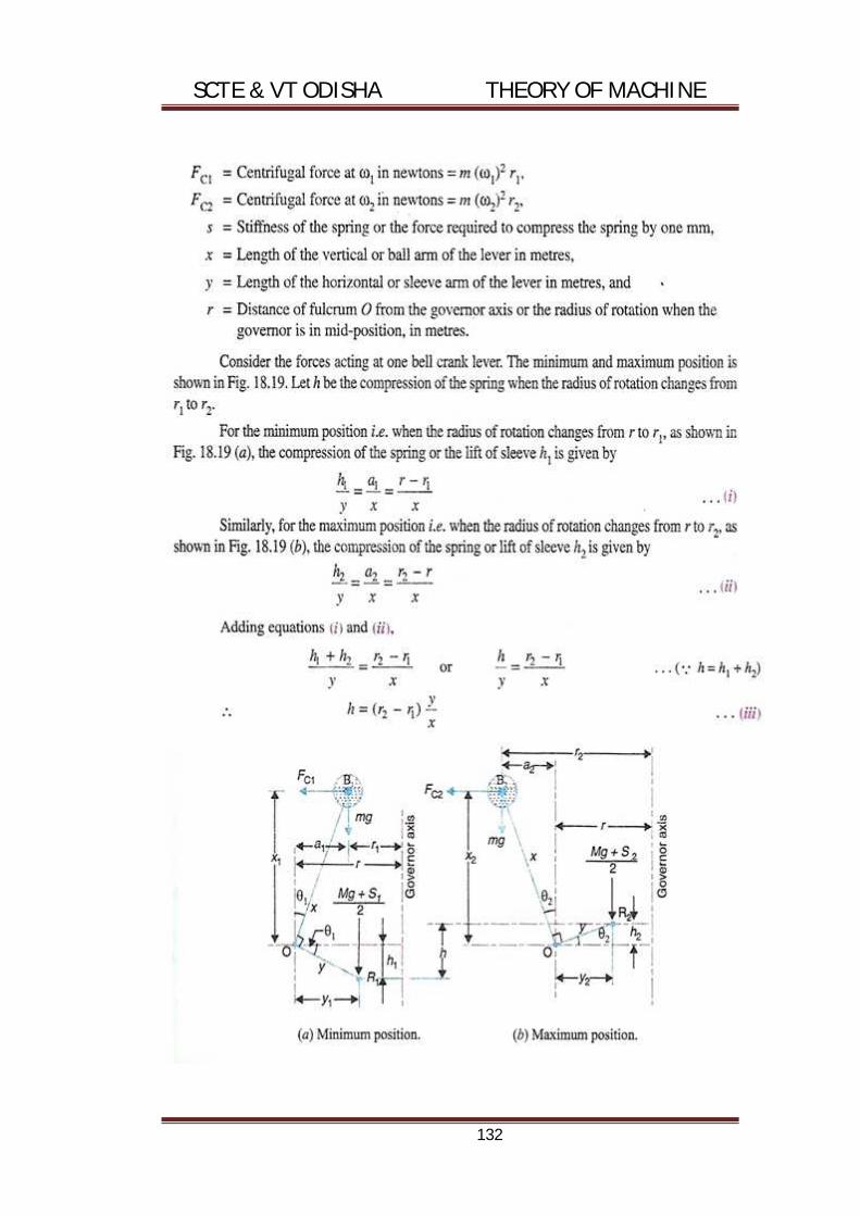
SCTE & VT ODISHA THEORY OF MACHINE
132

SCTE & VT ODISHA THEORY OF MACHINE
133

SCTE & VT ODISHA THEORY OF MACHINE
134
Example: A Hartnell governor having a central sleeve spring and two right-
angled bell crank levers moves between 290 r.p.m. and 310 r.p.m. for a
sleeve lift of 15 mm. the sleeve arms and the ball arms are 80 mm and 120
mm respectively. The levers are provided at 120 mm from the governor axis
and mass of each ball is 2.5 kg. the ball arms are parallel to the governor
axis at the lowest equilibrium speed. Determine :1. Loads on the spring at
the lowest and the highest equilibrium speeds, and 2. Stiffness of the spring.
Solution: Given:
N1 = 290 r.p.m.
or = 2 ×
=30.4 rad/s;
N2 = 310 r.p.m.
or = 2 ×
= 32.5
;
h = 15 = 0.015 ;
= 80 = 0.08 ;
= 120 = 0.12 ;
= 120 = 0.12 ;
= 2.5
1. loads on the spring at the lowest and highest equilibrium
speeds
Let:
S1 = spring load at lowest equilibrium speed, and
S2 = spring load at highest equilibrium speed.
Since the ball arms are parallel to governor axis at the lowest
equilibrium speed(i.e. at N1 = 290 r.p.m.), as shown in figure, therefore
r = r1 = 120 mm = 0.12 m

SCTE & VT ODISHA THEORY OF MACHINE
135

SCTE & VT ODISHA THEORY OF MACHINE
136
4.4 Conceptual explanation of sensitivity, stability and
isochronism.
Sensitiveness of governors: Consider two governor A and B running at the same speed. When
this speed increases or decreases by a certain amount, the lift of the sleeve
of governor A is greater then the lift of the sleeve of governor B. it is then
said that the governor A is more sensitive than the governor B.
In general, the greater the lift of the sleeve corresponding to a given
fractional change in speed, the greater is sensitiveness of the governor. It
may also be stated in another way that for a given lift of the sleeve, the
sensitiveness of the governor increase as the speed range decreases. This
definition of sensitiveness may be quite satisfactory when the governor is
considered as an independent mechanism.
But when the governor is fitted to an engine, the practical
requirement is simply that the change of equilibrium speed from the full
load to the no load position of the sleeve should be as small a friction as
possible of the mean equilibrium speed. The actual displacement of the
sleeve is immaterial, provided that it is sufficient to change the energy
supplied to the engine by the required amount. For this reason, the
sensitiveness is defined as the ratio of the difference between the maximum
and minimum equilibrium speeds to the mean equilibrium speed.
Let N1 = minimum equilibrium speed
N2 = maximum equilibrium speed, and
N = mean equilibrium speed
=
? h
=
=
( )
= ( )
………(in terms of angular speeds)

SCTE & VT ODISHA THEORY OF MACHINE
137
Stability of governors:
A governor is said to be stable when for every speed within the
working range there is a definite configuration i.e. there is only one radius
of the governor, if the equilibrium. For a stable governor, if the equilibrium
speed increases, the radius of governor ball must also increases.
Isochronous Governors
A governor is said to be isochronous when the equilibrium speed is
constant (i.e. range of speed is zero) for all radii of rotation of the balls
within the working range, neglecting friction. The isochronous is the stage
of infinite sensitivity.
Let us consider the case of a porter governor running at speeds N1,
N2 r.p.m. we have that
? ? =
( )
×
………………………. (i)
? ? =
( )
×
………………………. (ii)
For isochronisms, range of speed should be zero i.e. N2 – N1 = 0 or
N2 = N1. Therefore from equations (i) & (ii), h1 = h2, which is impossible in
case of a porter governor. Hence a porter governor cannot be isochronous.
4.5 Function of flywheel.
Fly wheel:-
A fly wheel is used in machines serves as a reservoir which stores
energy during the period when the supply of energy is more than the
requirement and relief during the period when the requirement of energy is
more than supply.
By supplying the required energy, a fly wheel controls the speed
variations caused by the cyclic fluctuation of the engine turning moment.

SCTE & VT ODISHA THEORY OF MACHINE
138
4.6 Comparison between flywheel & governor.
Governor Fly Wheel Its function is to regulate the supply of driving fluid producing energy, according to the load requirements so that at different loads almost a constant speed is maintained.
Its function is to store available mechanical energy when it is in excess of the load requirement and a part with the same when the available energy is less than that required by the load
It is provide on prime movers such as engines and turbines.
It is provided on engine and fabricating machines viz, rolling mills , punching machines shear machines, presses, etc.
It takes care of fluctuation of speed due top variation of load over long range of working of engines and turbines.
In engines it takes care of fluctuations of speed during thermodynamic cycle.
It works intermittantely i.e. only when ther is change in the load
It works continuously from cycle to cycle.
But for governor, there would have been uncessarily more consumpstion of driving fluid. Thus it economises its consumptions
In fabrication machines, it is very economical to use it as its use reduces capital investment on prime movers and their running expenses
Co-efficient of fluctuation of speed:-
The difference between the maximum and the minimum speed during a
cycle is called maximum fluctuation of speed.
The ratio of maximum fluctuation of speed to the mean speed is the co-
efficient of fluctuation of speed.
Cs =
where = Maximum speed in r.p.m during the cycle
N2 = minimum speed in r.p.m during the cycle
N = mean speed in r.p.m =

SCTE & VT ODISHA THEORY OF MACHINE
139
Cs =
Cs = 2.
Cs = 2.
Cs = 2.
4.7 Fluctuation of energy and coefficient of fluctuation of speed.
Fluctuation of energy:
1. The fluctuation of energy may be determined by the turning moment
diagram for one complete cycle rotation
2. The vibration of energy above and below the mean resisting torque
line in the turning moment diagram are called fluctuation of energy
3. The difference between the maximum and the minimum energy is
known as maximum fluctuation of energy.
Maximum fluctuation of energy:
A - G = mean torque line
Let a1, a3 and a5 = areas above the A-G line
Similarly a2, a4,and a6 = areas below the A-G line
Energy in the fly wheel at A=E
At B = E + a1
C = E + a1 – a2
D = E + a1 – a2 + a3
E = E + a1 – a2 + a3 – a4
F = E + a1 - a2 + a3 - a4 + a5
G = E + a1 - a2 + a3 - a4 + a5 - a6

SCTE & VT ODISHA THEORY OF MACHINE
140
Let greatest energy at B and least energy is at E.
Maximum energy = E + a1
Minimum energy = E + a1 – a2 + a3 – a4
Maximum fluctuation of energy,
? E = maximum energy – minimum energy
= E + a1 - ( E + a1 – a2 + a3 – a4)
CO-EFFICIENT OF STEADYNESS:-
It is the ratio of co-efficient of fluctuation of speed. M =
=
Co-efficient of fluctuation of energy:-
It is the ratio of maximum fluctuation of energy to the work done per cycle.
Mathematically = CE = ?
E = work done per cycle
Weight of the fly wheel:-
Let weight of the fly wheel, W= mg
Where m = mass of the fly wheel in kg.
Let K = radius of direction of fly wheel in metre.
I = mass moment of inertia of the fly wheel about its axis of rotation,
i.e; I = m.k2
And N2 = maximum and minimum speeds during the cycle in r.p.m
W1 and W2 = Maximum and minimum angular speed in radian/second
N =
W =

SCTE & VT ODISHA THEORY OF MACHINE
141
Cs =
=
Mean kinetic energy of the fly wheel, Em:-
Em = ½ I.W2
= ½ m.K2W2
Maximum fluctuation of energy = maximum K.E – minimum K.E
=
-
=
(
- )
=
?? - ?( + )?
= I.W( - )
= I. W2 ?
?
? = I.W2 Cs
I = ?
mk2 = ?
m = ?
I = ?
I = .
SCTE & VT ODISHA THEORY OF MACHINE
142
Problem:
A horizontal cross compound steam engine develops 300 kw at 900
r.p.m. The co-efficient of fluctuation of energy at found turning the diagram
is to be 0.1 and the fluctuation of speed is to be kept with +_0.5% of the
mean speed. Find the weight of the fly wheel if the radius of gyration is 2
metre.
ANS:-
Given data:
P = 300 KW
N = 90 R.P.M
Ce = 0.1
W =
=
× ×
= 9.42
Cs =
= 0.1
W1 = W2 = 0.5%×
= 1% of W
= 0.01W
= 0.0942
K = 2 mt
Work done/cycle = ×
= × ×
= 200000
? = E×
= 200× 1000 × 0.1
= 20,000

SCTE & VT ODISHA THEORY OF MACHINE
143
m = ?
=
× . × . = 5634.66
w = mg
= 5634.66× 9.81 = 55276.07 = 55.27kg.

SCTE & VT ODISHA THEORY OF MACHINE
144
Chapter-5
Balancing of Machine
Syllabus:
5.1 Concept of static and dynamic balancing.
5.2 Static balancing of rotating parts.
5.3 Principles of balancing of reciprocating parts.
5.4 Causes and effect of unbalance.
5.5 Difference between static and dynamic balancing
5.1 Concept of static balancing:
A system of rotating masses is said to be in static balance if the
combined mass centre of the system lie on the axis of rotation. The given
figure shows a rigid rotor revolving with a constant angular velocity
wrad/sec.
A no. of masses, say 3, are depicted by point masses at different radii
in the same transverses plane. They may represent different kinds of
rotating masses such as turbine blades, eccentric disc, etc. if m1, m2 and m3
are the masses revolving at radii r1, r2 and r3 respectively in the sam,e
plane then each mass produces a centrifugal force acting radially outwards
from axis of rotation.

SCTE & VT ODISHA THEORY OF MACHINE
145
Dynamic balancing:
When several masses rotate in different planes, the centrifugal
forces, in addition to being out of balance also forms coupkle. A system of
rotating masses is in dynamic balance when there doesn’t exist any resultant
centrifugal force as well as resultant couple:
In the work that follows the product of mr and mri (instead of mrw),
usually, have been reform as force and couple respectively as it is more
convenient to draws force and couple polygon with these quantities
If m1 m2 are two masses as in figure revolving diametrically
opposite to each other in different planes such that m1r1 = m2r2, the
centrifugal forces are balanced but an unbalanced couple of magnitude
m1r1i = m2r2i is introduced. The couple act in a plane that contains the axis
of rotation and the two masses. Thus, the couple is a constant magnitude but
variable direction.
5.2 Static balancing of rotating parts:
Consider a number of masses of magnitude m1,m2,m3,mc at distance
of r1,r2,r3,re from the axis of the rotating shaft. Let? ?? ?? ?? be the angles
of these masses with horizontal line OX.

SCTE & VT ODISHA THEORY OF MACHINE
146
If σ = 0 (Balancing state)
M1r1w2+m2r2w2+m3r3w2=0
? m1r1+m2r2+m3r3=0
σ = 0................................(i)
If not balance state then add mc .
m1r1w2 + m2r2w2 + m3r3w2 + mcrcw2 = 0
m1r1 + m2r2 + m3r3 + mcrc = 0
σ +mcrc=0.....................................(ii)
In components form
σ = 0
σ cos + mcrccos c=0
σ = 0
σ sin + mcrcsin c=0
mcrccos c=- σ cos ..........................................(III)
mcrcsin c= - σ sin
equation (III) (I) &(II) square & add
(mcrc )2cos2 c=(σ cos )2
(mcrc )2sin2 c=(σ sin )2
mcrc=? ?σ cos ?2 + (σ sin )2 -----------------(4)

SCTE & VT ODISHA THEORY OF MACHINE
147
Divided equation (II) & (III)
σ
σ
σ
σ
c= σ
σ
5.3 Principles of balancing of reciprocating parts.
For complete balancing of the reciprocating parts, the following
condition must be fulfilled:
1. Primary forces must balance, i.e. primary force polygon is enclosed.
2. Primary couples must balance, i.e. primary couple polygon is
enclosed.
3. Secondary forces must balance, i.e. secondary forces polygon is
enclosed.
4. Secondary couples must balance, i.e. secondary couple polygon is
enclosed.
Usually, it is not possible to satisfy all the above conditions fully for
a multicylinder engine. Mostly some unbalanced force or couple would
exist in the reciprocating engines.
Balancing of reciprocating masses:

SCTE & VT ODISHA THEORY OF MACHINE
148
Acceleration of the reciprocating parts is
aR = ? +
?
where ? = ratio of length & radious l/r.
Inertia force FI = m ? +
? (? × =Fr)
�FI = FR .
Where =FI
FU = FBH
� U = m ? +
?
= m +
FP(primary unbalanced forced) FS(secondary unbalanced force)
FP(max)= m (? = 90 = 1)
FS(max) = m

SCTE & VT ODISHA THEORY OF MACHINE
149
Balancing of several masses in difference planes:
σ =0
M1r1w2+m2r2w2+m3r3w2+mc1rc1w2+mc2rc2w
2=0
M1r1+ m2r2+ m3r3+ mc1rc1+ mc2rc2=0
σ + mc1rc1+ mc2rc2=0-------------------------------(I)
Taking moments about the point (I)
M1r1l1w2+M2R2L2W
2+M3R3L3W2+ Mc2Rc2Lc2W2=0
M1r1l1+M2R2L2+M3R3L3+ Mc2Rc2Lc2=0
σ Mc2Rc2Lc2=0----------------------(2)
σ
σ cos
σ
σ sin
cos σ
sin σ
SCTE & VT ODISHA THEORY OF MACHINE
150
Divided (II) by (I)
=
σ
σ
tan = σ
σ
Equation (I) in component for
σ = 0
σ + m r l cos + m r l cos = 0
σ = 0
σ + m r l sin + m r l sin = 0
cos
m r l cos = - ( σ + m r l cos )sin
m r l sin = - (σ + m r l sin )
Both side square & add.
(m r l ) cos =( σ + m r l cos )2
(m r l )2sin = (σ + m r l sin )
Mc1Rc1=
? ? σ + m r l cos ?2 + (σ + m r l sin )
Divided equation (II) by (I)
=
(σ )
( σ )
�tan = (σ )
( σ )

SCTE & VT ODISHA THEORY OF MACHINE
151
Causes & effect of unbalance:
Often an unbalance of force is produce in rotary or reciprocating machinery due to the inertia force associated with the moving masses.
Balancing is the force of designing or modifying machinery that the unbalanced is reducing to an acceptable and possible is eliminated entirely.
In a revolving centre the centrifugal force remains balanced as long as the centre of the mass of the rotor, lies on axis of the shaft when of the mass does lie on the axis or there is an eccentricity, an unbalanced force is produced.
This type of un balanced is very common in case of steam turbines rotors , engine crankshaft, rotary compressor & centrifugal force .
In high speed machinery, the unbalanced force results .there force attracted on the frame by the moving machine members a varying, impact vibration motion on the frame & produced noise . also there are hum an discomfort, determinable effect of machine performance & structural inter grids of the machine foundation .the most common approach lie balancing by disturbing them the mass which may be accomplished by addition or removal of mass from various machine members .
5.5 Difference between static and dynamic balancing:
Static balancing Dynamic balancing
It would refer to balancing in a single
plane
It would refer to balancing in more than
one plane
It is also known as primary balancing.
It is a balance force due to action of
gravity.
It is also known as secondary
balancing. It is a balance due to action
of inertia forces.
Rotation of fly wheels, grinding wheels,
car wheels are treated as static
balancing problems as most of their
masses concentrated in or very near one
plane.
Rotation of shaft of turbo-generator is a
case of dynamic balancing problems
Static balance occurs when the centre
of gravity of an object is on the axis of
rotation
A rotating system of mass is in dynamic
balance when the rotation doesn’t
produce any resultant centripetal force
of couple. Here the mass axis is
coincidental with the rotational axis.

SCTE & VT ODISHA THEORY OF MACHINE
152
Chapter-6
Vibration of machine parts
Syllabus:
6.1 Introduction to Vibration and related terms
(Amplitude, time period and frequency, cycle)
6.2 Classification of vibration.
6.3 Basic concept of natural, forced & damped vibration
6.4 Torsional and Longitudinal vibration.
6.6 Causes & remedies of vibration.

SCTE & VT ODISHA THEORY OF MACHINE
153
6.1 Introduction to Vibration and related terms (Amplitude, time
period and frequency, cycle)
Amplitude:
It is defined as its maximum displacement of a vibrating body from
its equilibrium position.
Time Period:
`It is the time taken by a motion to repeat itself, and is measured in
seconds.
Frequency:
Frequency is the number of cycles of motion completed in one
second. It is expressed in hertz (Hz) and is equal to one cycle per second.
DEFINITIONS:
I. Free (natural) vibrations elastic vibrations in which there is no
friction and external forces after the initial release of the body are
known as free or natural vibrations.
II. Damped vibrations when the energy of a vibrating system is
gradually dissipated by friction and other resistances, the vibrations
are said to be damped. The vibrations gradually cease and the system
rests in its equilibrium position.
III. Forced vibrations when a repeated force continuously acts on a
system, the vibrations are said to be forced. The frequency of the
vibrations is that of the applied force and is independent of their own
natural frequency of vibrations.

SCTE & VT ODISHA THEORY OF MACHINE
154
TYPES OF VIBRATIONS
Consider a vibrating body, e.g., a rod, shaft or spring. Figure shows a
mass less shaft, one end of which is fixed and the other end carrying a
heavy disc. The system can execute the following types of vibrations.
I. Longitudinal vibrations:
If the shaft is elongated and shortened so that the same moves up
and down resulting in tensile and compressive stresses in the shaft,
the vibrations are said to be longitudinal. The different particles of
the body move parallel to the axis of the body.
II. Transverse vibrations
When the shaft is bent alternately and tensile and compressive
stresses due to bending result, the vibrations are said to be
transverse. The particles of the body move approximately
perpendicular to its axis.

SCTE & VT ODISHA THEORY OF MACHINE
155
III. Torsional vibrations:
When the shaft is twisted and untwisted and untwisted alternately
and torsional shear stresses are induced, the vibrations are known as
torsional vibrations. The particles of the body move in a circle about
the axis of the shaft.

SCTE & VT ODISHA THEORY OF MACHINE
156
Free longitudinal vibrations:
The natural frequency of a vibrating system may be found by any of
the following method.
Equilibrium method:
It is based on the principle that whenever a vibratory system is in
equilibrium, the algebraic sum of forces and moments acting on it is zero.
This is in accordance with D’almbert’s principle that the sum of the inertia
forces and the external forces on a body in equilibrium must be zero.
Figure shows a helical spring suspended vertically from a rigid
support with its free end at A-A.
If a mass m is suspended from the free end, the spring is stretched by
a distance and B-B becomes the equilibrium position thus is the static
deflection of the spring under the weight of the mass m.
Let s = stiffness of the spring under the weight of the mass m.
In the static equilibrium position,
Upward force = downward force

SCTE & VT ODISHA THEORY OF MACHINE
157
S× ? = mg
Now, if the mass m is pulled father down through a distance x, the
forces acting on the mass will be
Inertia force = m ?(upwards)
Spring force(restoring force) = sx (upwards)
(x is downward and thus velocity ? ? also
downwards)
As the sum of the inertia force and the external force on the body in
any direction is to be zero (D’alembert’s principle),
m ?+ = 0
If the mass is released, it will start oscillating above and below the
equilibrium position. The oscillation will continue for ever if there is no
frictional resistance to the motion.
The above equation can be written as
?+ ?
? =0
This is the equation of a simple harmonic motion and is analogous to
?+ =0
The solution of which is given by
x = A sin +
Where A and B are the constants of integration and their values depend
upon the manner in which the vibration starts. By making proper
substitutions, other forms of the solution can also be obtained as follos:
· By assuming A = X cos and B = X sin
x = x(sin t.cos + cos t.sin )
= xsin( + )

SCTE & VT ODISHA THEORY OF MACHINE
158
Where X and are the constants and have to be found from initial
conditions.
· By assuming A= X sin and B = X cos
x= X(sin t.sin + cos t.cos )
= x = X.cos( - )
Where X and are the constants and have to be found from initial
conditions. The above solutions show that the system vibrates with
frequency.
= ?
.
Which is known as the natural circular frequency of vibration. As
one cycle of motion is completed in an angle 2 , the period of vibration is
T =
= 2 .?
and, natural linear frequency of the
vibrating system,
fn =
=
?
.
In general, the words circular or linear are not used in natural
circular frequency or in natural linear frequency. Both are known as natural
frequencies of vibration and are distinguished by their units.

SCTE & VT ODISHA THEORY OF MACHINE
159
Free torsional vibrations (single rotor)
Consider a uniform shaft of length/rigidly fixed at its upper end and
carrying a disc of moment of inertia/ at its lower end. The shaft is assumed
to be massless. If the disc is given a twist about its vertical axis and then
released, it will start oscillating about the axis and will perform torsional
vibrations.
Let:
= angular displacement of the disc from its equilibrium position at
any instant
q = torsional stiffness of the shaft
= torque required to twist the shaft per radian within elastic limits
=
where G = modulus of rigidly of the shaft material
J = poler moment of inertia of the shaft cross-section
At any instant, the torques acting on the disc are
· Inertia torque =
· Restoring torque(spring torque) =
Negative signs have been used as both of this torques act opposite to the
angular displacement. For equilibrium, the sum of all torques acting on the
disc must be zero.

SCTE & VT ODISHA THEORY OF MACHINE
160
Therefore, ? + = 0
Or ?+
= 0
This is the equation of simple harmonic motion.
= ?
=
?
Causes & remedies of vibration:
Causes of vibration:
Some of the important causes of vibration in machines are listed
below
1. Unbalanced reciprocating machine parts
2. Unbalanced rotating machine parts
3. Incorrect alignment of the transmission elements such as coupling
etc
4. Use of simple spur gears for power transmission
5. Warm-out teeth of the gears of the power transmission
6. IOmpact taking parttsd of ther machine of axplosion or impact of
working fluids of prime movers
7. Loose transimission bekts and chains.
8. Loose fastenings of the moving parts.
9. Vibration waves from other sources and machines installed neardy,
due to improper isolatrion of vibrations from them.
10. Due to more material constact such as bases plates on the
foundations for the pedestal bearings.
11. Non-rigid machine foundations due to lack of compact soil below,
causing settlement of machine compounents.

SCTE & VT ODISHA THEORY OF MACHINE
161
Remedies of vibration:
Although it is impossible to eliminate the vibrations, yet these can be
reduced by adopting various remedies, some of the remedies are listed
below:
1. Partial balancing of reciprocating masses.
2. Balancing of unbalanced rotating masses.
3. Using helical gears instead of spur gases.
4. Proper tightening and locking of fastening and periodically
ensuring it again.
5. Correcting the mis-0alingnmemnt of rotating components and
checking it from time to time.
6. Timly replacement of work-out moving parts, slides and bearings
with excessive clearance.
7. Isolating vibrations from other machines and sources by
providing vibration insulation pads in the machine foundations.
8. Making machine foundatioins on compact ground and making
them sufficiently strong, so that they do not yield or settle under
the load of the machine.