theory of the verge & foliot clock of the ... - hsn entry page
TRANSCRIPT
2
1
Theory of the Verge & Foliot Clock of the Early Medieval Age By Dieter Roess1
1. Verge & Foliot and Pendulum Escapements
Since the middle of the 13th century until the introduction of pendulum clocks in the 17th century, verge and foliot escapements have been used in large turret clocks and also in room clocks.
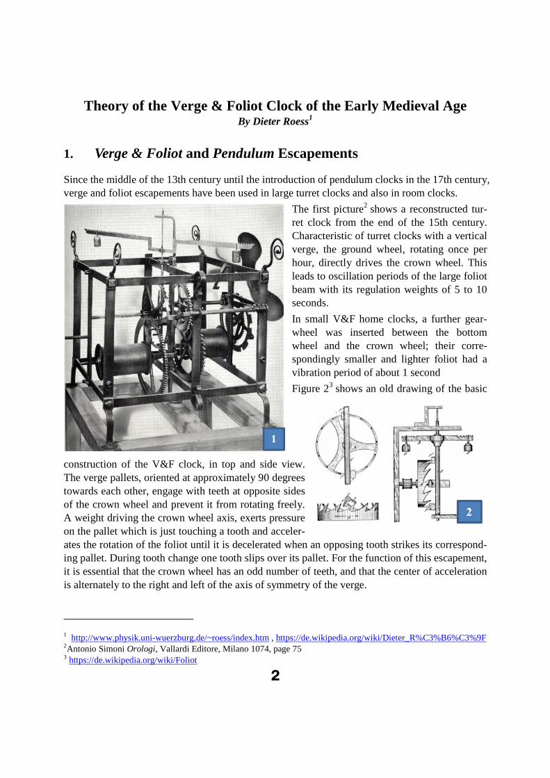
The first picture2 shows a reconstructed tur-ret clock from the end of the 15th century. Characteristic of turret clocks with a vertical verge, the ground wheel, rotating once per hour, directly drives the crown wheel. This leads to oscillation periods of the large foliot beam with its regulation weights of 5 to 10 seconds.
In small V&F home clocks, a further gear-wheel was inserted between the bottom wheel and the crown wheel; their corre-spondingly smaller and lighter foliot had a vibration period of about 1 second
Figure 23 shows an old drawing of the basic
construction of the V&F clock, in top and side view. The verge pallets, oriented at approximately 90 degrees towards each other, engage with teeth at opposite sides of the crown wheel and prevent it from rotating freely. A weight driving the crown wheel axis, exerts pressure on the pallet which is just touching a tooth and acceler-ates the rotation of the foliot until it is decelerated when an opposing tooth strikes its correspond-ing pallet. During tooth change one tooth slips over its pallet. For the function of this escapement, it is essential that the crown wheel has an odd number of teeth, and that the center of acceleration is alternately to the right and left of the axis of symmetry of the verge.
1 http://www.physik.uni-wuerzburg.de/~roess/index.htm , https://de.wikipedia.org/wiki/Dieter_R%C3%B6%C3%9F2Antonio Simoni Orologi, Vallardi Editore, Milano 1074, page 75 3 https://de.wikipedia.org/wiki/Foliot

3
Probably none of the large V&F clocks were preserved in their original state, as the conversion to a pendulum clock was technically simple and brought a noticeable gain in accuracy. There is no reliable historical testimony about the operability of the original escapements, except for a bad reputation with unclear source of daily deviations from the solar time of ±15 minutes.
This escapement is often denied the property of an oscillator at all4.
For a new V&F construction equipped with modern sensors, the author5 showed that the V&F clock has a high intrinsic repeatability, with hourly deviations of a few seconds. The long-term accuracy was limited in these experiments by the temperature dependence of the oscillation, which was about 1 minute per day and degree Celsius.
A theory of the V&F escapement is developed in in this paper, together with the description of a numerical solution6 in form of a simulation program available to the reader. In the following pag-es
The geometry of the V&F escapement is analyzed in detail.
A model of angle-dependent friction is developed, as friction between the verge pallet and
crown-wheel tooth is of a crucial importance.
As basic of the dynamics, a nonlinear differential equation is derived from basic princi-ples, starting with the law of energy conservation. Because of its nonlinearity, combinedwith large arcs of vibrations, no analytic solution is feasible.
As numerical solution, an interactive Java-simulation program for the PC is presented, us-ing the Runge-Kutta-4 algorithm. The simulation calculates and visualizes the timing ofthe oscillation, its phase diagram, and the geometry of the oscillation sequence for arbi-trary values of parameters. The user can experiment with the model on his computer aswith a real escapement, yet much more flexible and faster.
In each step, a comparison to the pendulum is drawn, as example of a familiar oscillatorin horology.
The result of this analysis is a mathematical model. Predictions on its basis will be as good as the model approaches reality. Measurements made by different authors on four new or old V&F clocks confirm results of the model; thus it may be a reasonable approximation. Those experi-mental tests will be reported elsewhere.
4 For example Kees Grimbergen “Huygens and the advancement of time measurements” Proceedings of the Interna-
tional Conference "Titan - from discovery to encounter", 13-17 April 2004, ESTEC, Noordwijk, Netherlands. Ed.:
Karen Fletcher. ESA SP-1278, Noordwijk, Netherlands: ESA Publications Division, ISBN 92-9092-997-9, 2004, p. 91 – 102 5 https://pawn.physik.uni-wuerzburg.de/~roess/NichtSoWichtiges.htm; this file contains an early version of the pre-sented theory and an experimental paper on a newly constructed V&F clock.
6 Prior papers on V&F theory are discussed in the last paragraph.

4
4
2 Geometry of the V&F Escapement
2.1 Stripping the escapement from auxiliary elements
In a real V&F clock, the function of its oscillator can be clouded by its combination with other elements. The driving weight does not exert pressure directly to the crown wheel teeth of the es-
capement, but via a gear formed of bottom (hour) wheel and lantern pinion, reducing the movement of the weight
compared to that of the crown wheel by a gear factor of the order of 10.
A real clock needs an hour wheel, which digitally triggers the bell mechanism at intervals of one hour. It also drives in an analogue way the hands of the dial. These elements introduce friction and irregularities, that have nothing to do with the basic function of the escapement oscillator.
For our model analysis we strip the escapement of these auxiliary functions, as shown in figure 3. We will later discuss the influence of those on the intrinsic operation of the oscillator.
The drive weight G now directly applies torque to the teeth of the crown wheel. In a real clock its relation K to the mass of the clock weight is determined by gear and leverage ratios:
2.2 Drop
When the pallet releases a tooth, its opposing tooth must not yet be in contact with its pallet. Oth-erwise the escapement is blocked. There must be a minimum interval determined by mechanical
tolerances, or intentionally set, in which both pallets are free of contact. As consequence, after release the
opposing tooth will fall freely onto the opposing pallet. The path of this free fall is called “drop”. It is meas-ured in relation to the tooth distance, the distance of two neighbored teeth along the circumference of the crown wheel. Drop will be discussed in detail later.
pinions of lantern pinion diameter of bottom wheel*
teeth of bottom wheel diameter of crown wheel
GK
M

5
2.3 Maximum arc and weight oscillation
In the V&F escapement shown in figure 3, potential energy of the drive weight is periodically transformed into rotational energy of the foliot7, and vice versa.
For comparison, in the pendulum potential energy of the pendulum bob mass is periodically transformed into rotational energy of the identical bob mass.
Under the torque of the weight G the upper tooth of the crown wheel exercises a corresponding torque to the upper pallet of the verge, setting the inertia of the verge with its attached foliot into motion. After some angle of rotation, the tooth will escape its pallet, and the opposite tooth of the crown wheel will fall onto its corresponding lower pallet, decelerating and reversing the rotation.
After a full period of foliot oscillation with two tooth escapes, the weight has experienced a final
descent, which is equal to the tooth distance at the crown wheel (in a clock with bottom wheel, the observed descent is reduced by the ratio K).
In addition, the weight will perform a periodic up and down oscillation in the process of accelera-tion and deceleration of the foliot, the amplitude of which depends on the amplitude of the verge and foliot oscillation, measured at the rim of the crown wheel.
The oscillation amplitude is limited by the geometry of the escapement. The following drawings illustrate limiting positions with a vertical look along the verge. In Figure 5 geometric terms used are illustrated (all following figures of the geometry are taken from the simulation windows).
L: Length of the pallet, measured from the axis of the verge
d: distance of the tooth tip to the axis of the verge
: angle between the pallets (commonly between 80 and 100 degrees)
escape angle of the pallet against the horizontal
Arc: escape angle of rotation, measured from the pallet symmetry plane
upper pallet and tooth: blue colour
lower pallet and tooth: red colour
In most formulas the ratio of some variable to the pallet length will appear. Therefore, it is useful to normalize geometrical dimensions to the pallet length L. With this definition, we will use the term engagement depth for the ratio d/L, and will just write d most times, with L = 1. To arrive at real numbers, one just multiplies normalized dimensions by the length of the pallets.
In figure 5 the blue tooth is in danger of swinging out of contact with its pallet, while the opposite
pallet is free. The limiting arc results as
7 More accurately one should also consider the rotational energy of crown wheel, bottom wheel, and verge. Their in-ertia can be interpreted as an additional small inertia of the foliot in an idealized wheel train with negligible mass.

6
Figure 6 shows the relation of the maximum arc to the pallet angle as a function of d/L, with the pallet angle as parameter of the different curves.
For medium engagements depth d/L the maximum arc can be some 10% higher than the pallet angle
The maximum G-amplitude of the weight oscillation in relation to the pallet length is shown as a dotted red line. For medium engagement it can be at about 70% higher than the pallet length.
Figure 7 shows a typical situation of tooth escape, at = 90o and d/L = 0.5. The blue tooth has just left its pallet, and the red one catches its one. The path in between is half the tooth distance Z. with Z the distance of two neighbored teeth along the circumference of the crown wheel.
2 22
2
2
2
sin 1 ( 1)
arcsin 1 ( arcsin : arc sine)
Arc arcsin 12
Arc 1
2
G-Ampl 2 1 2sin( )
L dd L
L
d
d
d
22 1 ( ) x d
L L
5

7
8
L
The tooth distance Z and hence the travel of G is a bit larger than twice the pallet length.
The results for d = 0.5 engagement and g = 900 pallet angle can be summed up as:
The descent of the weight per period is 1 tooth distance
The maximum tooth distance is 2.3 times the pallet length
The maximum oscillation amplitude of a crown wheel tooth is 1.7 times the length of thepallet.
Hence the maximum weight oscillation amplitude for these parameters is at best1.7 / 2.3 = 75% of the descent of the weight per period.
Figure 8 shows the dynamics of the weight oscillation, derived as the movement of a tooth during one period from the simulation program; with careful inspection such a curve can be observed at a real clock, even though barely in such detail.
The oscillation starts with the (upper) pallet parallel to its tooth face. The sharp kink signals the escape of the tooth with reversal of the rotation of the crown wheel; this is shown both with and without drop involved. Thereafter the crown wheel swings back under the pressure of the oppo-site pallet and then reverses its direction. At the end of the period the opposite (lower) pallet es-capes. Between escapes one observes soft kinks caused by the change of leverage from the end of the pallet to its face.
The amplitudes of the oscillation are shown and compared to the total movement of the tooth at the right side. As derived above, without drop the amplitude of the G- oscillation is about 70% of the G descent. Drop deteriorates this relation and reduces the oscillation period (the graph is tak-en at similar weight, amplitude and friction coefficient.
2
0 0
0600.5; ; sin 1 0.54
2(sin(60 ) 0.5 tan(30 )) 2.35
da
L
Z

8
9
101
2
2
2
Z Z
Z Z
2.4“No blockage” condition
The relation of the maximum tooth distance to the pallet length results from the condition of “no-blockage”: the two pallets cannot contact their teeth at the same angle (same time in oscillation). Two such limits exist.
The first limit situation is shown in figure 9. When the blue pallet leaves its tooth, the red one is just touching the tip of its tooth. The distance of the opposite tooth tips corresponds to half the tooth distance Z on one side.
The geometry results (in normalized terms) in
This is the upper Limit of the tooth distance, to allow escape of the blue tooth.
At smaller pallet angle, the escape situation of figure 10 occurs, where the red tooth hits its pallet at the flank. The geometry of this second limit results in
2 21
2
2 22 1 2
1 sin sin 1
sin( )
2 2 1 sin(asin 1 )
yd a d
L
y
d
Z y yd d
L L
The transition is at 2sin
: tooth distance
Z
Z
The border conditions are
2 21
2
2 21 1 2
1 sin sin 1
( )
2 2 1 (asin 1 )
yd a d
L
ytg
d
Z y yd tg d
L L
9
11
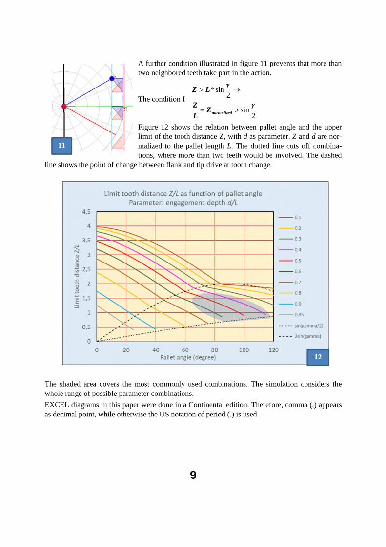
A further condition illustrated in figure 11 prevents that more than two neighbored teeth take part in the action.
The condition I
*sin2
sin2
normalized
Z L
ZZ
L
Figure 12 shows the relation between pallet angle and the upper limit of the tooth distance Z, with d as parameter. Z and d are nor-malized to the pallet length L. The dotted line cuts off combina-tions, where more than two teeth would be involved. The dashed
line shows the point of change between flank and tip drive at tooth change.
The shaded area covers the most commonly used combinations. The simulation considers the whole range of possible parameter combinations.
EXCEL diagrams in this paper were done in a Continental edition. Therefore, comma (,) appears as decimal point, while otherwise the US notation of period (.) is used.

10
2.5 What happens to the energy of the descending weight? Energy balance and sensitivity to external influences
After one period, the weight G has suffered a perpetual descent of one tooth distance. What hap-pens with this lost energy?
It must be consumed in the escapement by friction to arrive at a dynamic equilibrium. If friction is too low the foliot will gain rotational energy at each oscillation and the verge will run out of
contact.
The amount of lost energy in question is substantial. It was shown above that it is of the same or-der as the dynamic energy of the oscillator.
This is typical of the V&F escapement, where the functions of directional switch of the torque and execution of the torque to the rotating part for the compensation of friction are combined in the same element, the verge.
In contrast, in the pendulum escapement both functions are separated: the pendulum controls the direction of the torque by the reversion of its path against the unidirectional gravity, while some independent lever supplies energy lost by friction at the right phase. This separation allows a bet-ter relation between the energy lost per period and the one stored in the oscillating element. The same holds in the anchor escapement with balance and spring: direction reversal is obtained by the spring, while torque is exerted by the anchor.
It the V&F escapement energy is mostly consumed by friction between crown wheel tooth and pallet (in a real clock some smaller part is consumed by friction at the bearings of verge and crown wheel, and of the bottom wheel and its accessories).
The zero-speed friction in bearings and at the pallets defines a minimum G to start motion of the foliot. Any additional weight will drive the oscillation against the friction at the pallets.
For the escapement to arrive at a stable oscillation arc, the potential energy of the drive weight must be in equilibrium with the rotational energy of the foliot plus the friction loss.
From these general considerations it results that the oscillation energy of the ideal V&F, and hence its amplitude and frequency depend on
Drive weight G
Inertia of the foliot
Friction
Sufficient constancy of the weight can be assured by simple means. For example, a slight taper in the rope barrels will counteract the increasing weight of the lowering rope; such a device has been observed in an old V&B clock owned by the author.
Intentional changes of the inertia via the position of the cursors (also called timing weights) on the foliot, are utilized to regulate the frequency. Thermal expansion of the foliot is too small to be of practical importance for its frequency (see later).
The essential influences on the constancy of the oscillator are changing conditions of friction.
One relatively trivial such influence is air resistance of the rotating foliot. Its contribution will change linearly with air pressure.

11
14
13
The influence of surface conditions on the friction between tooth and pallet are more important and more complicated. Friction generally depends on a more or less constant friction coefficient, on the speed of relative motion and on the pressure exercised normal to the surface. Speed and the direction of normal pressure vary during the oscillation, depending on the arc of oscillation.
The friction coefficient characterizes the surface conditions (roughness), the materials of the fric-tion partners and any lubricant in between them.
Looking at the simple drawings above, one might imagine that either the flat end line of the pallet is rubbing on the flat upright surface of the tooth, or that the flat tip of the tooth is rubbing on the flat pallet. In reali-ty the tooth is rotating perpendicular to the rotation axis of the pallet, and hence for flat surfaces the contact is not a line but a point (figure 13). It is a line only when both are parallel. Otherwise the contact point will wan-der up and down.
Even if the torque exercised by the weight is moderate, the pressure at the contact point is very high because of the small contact area.
At high pressure, the role of the lubricant is important and can be quite unexpected. All lubricants strongly decrease in viscosity at increasing
temperature8. While at low pressure this can decrease friction with increasing temperature, it can increase friction at high pressure, when the lubricant is pressed out of the contact zone, with liq-uid contact changing to partially solid-state contact9.
An important conclusion is, that temperature influence will depend on the absolute amount of pressure, and hence on the weight driving the escapement. Otherwise the same frequency can be obtained over a wide range of driving weight by proper choice of inertia of the foliot.
2.6 Verge, crown wheel and drive weight interaction
In the V&F, the motion of weight G, crown wheel tooth, verge and foliot are strictly clamped to-gether, except in the short phase of drop. The geometry of the motion is described by the height h
of the weight G and by the angle of rotation of verge and foliot. With G acting at the rim of the crown wheel (figure 3), h is also the position of the crown wheel tooth, except of a constant dis-tance.
For the pendulum (figure 14), a simple geometric function re-
lates the height of the bob G and its angular deflection from the vertical symmetry position
cosh
L .
It is characterized by a single trigonometric function (cosine
8 „no lubricant“ is also some lubricant. Only for freshly cleaved surfaces under vacuum one observes pure solid- state
friction. In air some lubricating film develops soon. 9 Stribeck. Kurve, e.g. https://de.wikipedia.org/wiki/Stribeck-Kurve

12
15
and a single geometric dimension (the pendulum length L).
In the V&F, two different trigonometric functions (sine and tangent) connect the path of the tooth (and hence of G) with the rotation of the foliot, applied to 2 different dimensional values
L: (Length of the pallet).
d: distance of the crown wheel tip from the axis of the verge
This is shown in figure 15.
The relations between the position h of the crown wheel tooth (equal to the height of weight G) and the angle of deflection of the verge (foliot) are:
: progression of the tooth tip along its path
Pallet driven by tooth tip
* ( ) >2
Pallet driven by tooth flank
*cos( ) <2
h
h d tg
h L
In a half-oscillation 2 different succes-sive accelerating and 2 different decel-erating phases follow each other; their order is reversed in the back half-oscillation. In addition, there are 2 points where the leverage of the drive jumps from d to L.
Figure 16 illustrates this consecution of phases in detail. In the electronic edi-tion, for the sake of clarity, you can en-large it (as all other graphs in this text and in the simulation) by pulling it up
to screen size.
We look at the center of the verge axis from above, and start at the top left graph.
Two pallets at an angle close to 90 de-grees protrude from the verge. The blue pallet should be the top one; the red one is displaced downwards by the diameter of the crown wheel. The black foliot bar is shown symmetrical to the verge pallets. The oscillation arc is measured from the x axis to the green symmetry axis of the pallets (in the start graph it is negative: -860).

13
The distance between two blue or red teeth of the crown wheel is the tooth distance Z. One blue tooth engages with the blue pallet and accelerates it upwards (increasing angle) under the influ-ence of the lowering drive weight (blue arrow). The movement of the tooth corresponds to the movement of the drive weight.
The red teeth can only interact with the red pallet. In the first graph they are out of contact. They move in the opposite direction to the blue teeth.
Since the crown wheel has an odd number of teeth, the sum of the sign-correct distances of a blue tooth and the corresponding red tooth from the x axis is constant and equal to one half the tooth distance.
The plane of the tooth tips (green line) are at a distance d (engagement) from the verge axis. The (minimal) tooth base (red-blue line) is at a distance L (pallet length, measured from the verge axis to the pallet rim).
The back flank of the teeth is important in its shape only insofar, as the tip must be able to pass along the pallet. A pin with sharp tip would suffice. In the simulation, a linear back-flank is adapted to the engagement d in such a way that passing is possible.
The point of interaction between the tooth and the pallet is highlighted with a colored point.
Following this explanation, we now look at snapshots from the phases of a full swing. The first 4
pictures show the forward, the second four the backward swing.
The upper left shows the starting point of a period of oscillation when the foliot is at rest and the drive weight is at rest too. Then the blue tooth accelerates the blue pallet with its flank. As soon
as the angle is -/ 2 (the blue pallet points in the direction of the x axis), the point of attack of the
tooth jumps to the tooth tip. The palette slides on it until it loses contact (third graph).
At this moment, the red pallet hits the tip of the red tooth. This is the moment of the maximum angular speed and up to this point the drive weight has dropped. The momentum of the swinging Foliot drives the red tooth (and thus also the blue one) counter to the drive direction, so that the
driving weight is raised while the angular speed of the Foliot decreases. When the angle is +/ 2(red pallet points in the direction of the x axis), the point of attack jumps from the tip to the edge. As soon as the rotational energy of the V&F has been absorbed by lifting the weight (and by fric-tion), it comes to rest and begins the backward swing (fifth graph).
Now the red tooth accelerates the red pallet. Again, the point of attack jumps from the flank to the tip (sixth graph)). The blue pallet passes the back of the blue tooth and finally meets the front flank of the next blue tooth (seventh graph), which starts deceleration). Again the point of attack jumps from, tip to flank (eighth graph).
Finally, the movement will end near the starting angle with a momentary rest, and a new period of oscillation begins. Since, in the cycle, the crown wheel has advanced by one tooth, the drive weight suffers a corresponding permanent energy loss.
The consecution of phases leads to periodic change of the geometric relations between angle and weight height both in character and in sign. This is considered in the simulation algorithm.

14
2.7 Modelling friction
Friction is a complicated physical process. We use a generally accepted simplified model, which considers the geometry and dynamics of the process, but does not claim to include all details of the materials (tooth, pallet and lubricant) in the friction zone.
The model is;
Friction = R * Absolute value of the sliding speed v * contact pressure D
R is a constant friction parameter which mainly characterizes the smoothness and lubrication of pallets and teeth flanks. The contact pressure P is defined by the drive weight G and by the slid-ing angle, which in turn depends on the pallet deflection.
The important part of friction in the V&F escapement is the one between crown wheel tooth and pallet.
One must consider two different cases:
The pallet edge slides along the tooth flank10.
The tooth tip slides along the pallet plane
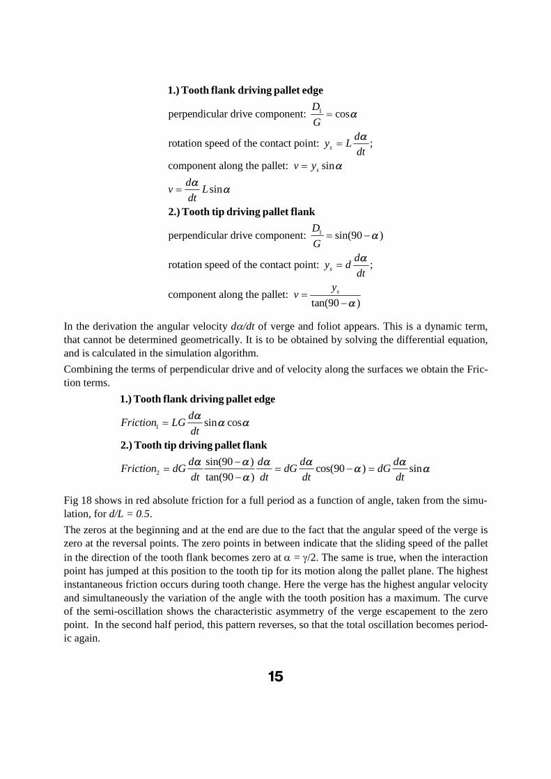
Figure17 shows the geometric relationship for the power applied to the verge pallet and for the speed along the surfaces.
10 We assume the flank to be perpendicular to the base. Undercut complicates the formulas but brings no important additional insight.
15
1perpendicular drive component: cos
rotation speed of the contact point: ;
component along the pallet: sin
sin
s
s
D
G
dy L
dt
v y
dv L
dt
1.) Tooth flank driving pallet edge
2.) Tooth tip driving pallet fl
1perpendicular drive component: sin(90 )
rotation speed of the contact point: ;
component along the pallet: tan(90 )
s
s
D
G
dy d
dt
yv
ank
In the derivation the angular velocity d/dt of verge and foliot appears. This is a dynamic term, that cannot be determined geometrically. It is to be obtained by solving the differential equation, and is calculated in the simulation algorithm.
Combining the terms of perpendicular drive and of velocity along the surfaces we obtain the Fric-tion terms.
1
2
sin cos
sin(90 )cos(90 ) sin
tan(90 )
dFriction LG
dt
d d d dFriction dG dG dG
dt dt dt dt
1.) Tooth flank driving pallet edge
2.) Tooth tip driving pallet flank
Fig 18 shows in red absolute friction for a full period as a function of angle, taken from the simu-lation, for d/L = 0.5.
The zeros at the beginning and at the end are due to the fact that the angular speed of the verge is zero at the reversal points. The zero points in between indicate that the sliding speed of the pallet
in the direction of the tooth flank becomes zero at = /2. The same is true, when the interaction point has jumped at this position to the tooth tip for its motion along the pallet plane. The highest instantaneous friction occurs during tooth change. Here the verge has the highest angular velocity
and simultaneously the variation of the angle with the tooth position has a maximum. The curve of the semi-oscillation shows the characteristic asymmetry of the verge escapement to the zero point. In the second half period, this pattern reverses, so that the total oscillation becomes period-ic again.

16
18
For comparison, the friction) of a pendulum (e.g. by air resistance) is shown in magenta, at slightly different fre-quency. Here the relation is very simple:
cos ; sin ; sinh dh
L R RLL dt
The pattern of a pendulum half wave is of course sym-
metric to the center, in contrast to the V&F.
Considering friction in the simulation program, it is use-ful to distinguish between the drive weight G itself as a cause of friction and its relation A to the moment of iner-
tia of the foliot. While this relation mainly determines the period, the weight is also directly relat-ed to friction. In the simulation, 2 sliders for the variables A and G are accordingly provided. As long as A remains constant, only friction (not the coefficient of friction R) is changed with the variation of G.
2.8 Modeling drop
Drop exists when at tooth change the new tooth has a finite distance from its pallet. It then drops quickly onto the pallet. In this short transition period there is no contact between verge and crown wheel and therefore no friction at the pallets. The speed of the drop is limited by the inertia of crown wheel, which is accelerated by the fall of the weight during drop. At the end of drop the extra energy gained in the crown wheel decelerates the verge in a short impulse.
Drop causes a decelerating impulse and should not be misunderstood as the driving (accelerating) agent in a verge escapement! (see the literature discussion in chapter 7.1)
Although the impulse can be violent and acoustically striking at a high drive weight and large an-gle, the effect of moderate drop on the oscillation behavior of the foliot is low, since its duration is short and thus its energy content limited. Its average effect is similar to an increase of friction in a system without drop.
In practice, excessive drop is a cause of pitting at the pallet surfaces and exerts high strain on the crown wheel bearings. Part of its energy is lost to the oscillator and converted to acoustic excita-tion of air and frame.
Drop is considered as a parameter in the simulation of the V&F. It is modelled to accumulate the weight descent energy of the weight for the short time period of drop (0.05 s) and transfer it to
the pallet in a decelerating pulse.
17
22
2
2
2
2
2
2
2
2
constant2 2
0
0;
: angular acceleration
-
J J dGgh Ggh C
dt
dh d dGg J
dt dt dt
dh dh d
dt d dt
dh d d dGg J
d dt dt dt
d
dt
d
d Gg dh
Jdt
d
d
t
Energy law
differentiate (t)
cancel
3 Differential Equation and Dynamics of the V&F Oscillator
3.1 Friction free case
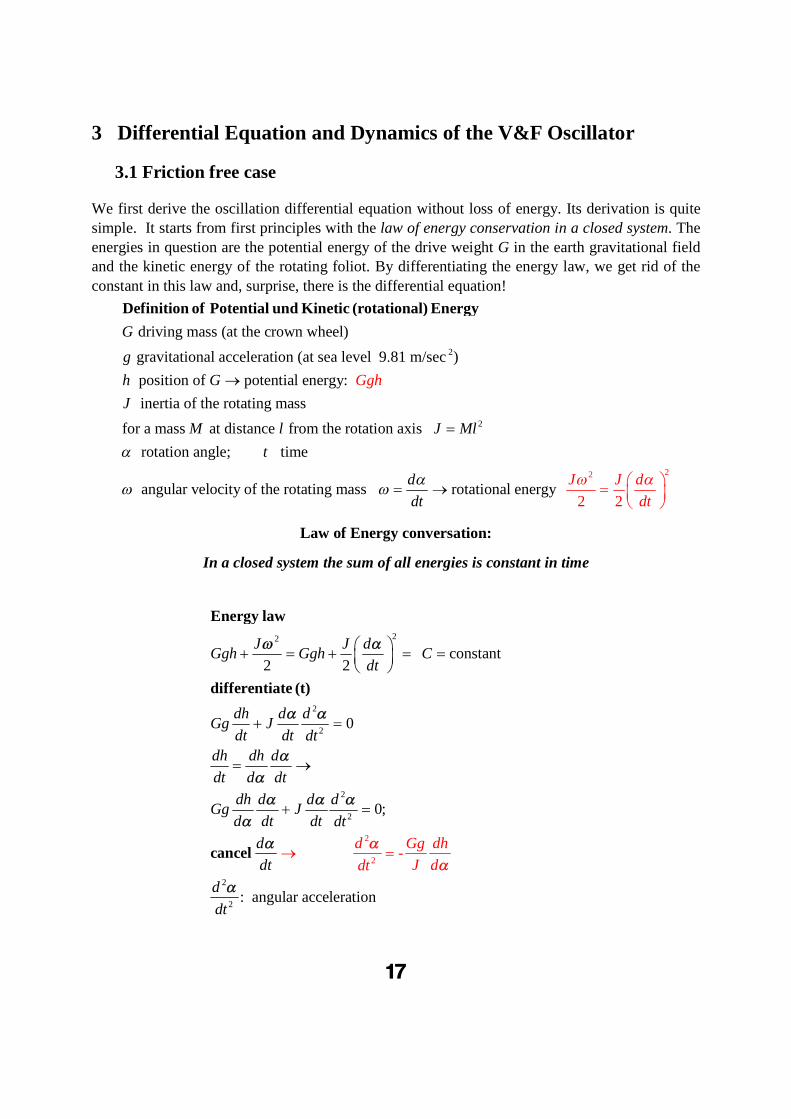
We first derive the oscillation differential equation without loss of energy. Its derivation is quite simple. It starts from first principles with the law of energy conservation in a closed system. The energies in question are the potential energy of the drive weight G in the earth gravitational field and the kinetic energy of the rotating foliot. By differentiating the energy law, we get rid of the
constant in this law and, surprise, there is the differential equation!
2
driving mass (at the crown wheel)
gravitational acceleration (at sea level 9.81 m/sec )
position of potential energy:
inertia of
G
g
h G Ggh
J
Definition of Potential und Kinetic (rotational) Energy
2
2
2
the rotating mass
for a mass at distance from the rotation axis
rotation angle; time
angular velocity of the rotating mass rotational energy2 2
M l J Ml
t
d
dt
J J d
dt
Law of Energy conversation:
In a closed system the sum of all energies is constant in time

18
This second-degree differential equation applies to all systems in which energy is exchanged be-tween potential energy and rotational energy without energy loss. The determining variable is the ratio between a change in the weight height and the associated change in the rotation angle. If the
relation between h and is known, one obtains dh/d by differentiation. We have derived h()-
relations in the preceding chapter on geometry, both for the V&F and for the pendulum; So all necessary concatenations are known and we have just to solve the differential equation to get the full dynamics of the system.
3.1.1 Ideal pendulum
For the ideal pendulum we had found
2
2
2
2
2 2
sin
cos
With the mass of the bob and the pendulum length
2 cos 2
2
-
cos
h L
dhL
d
LG L J G
d Gg dh
J
d Gg gL
Ldt GL
ddt
Remarkably, the mass G of the bob does not enter, as it appears both in the driving mass and in the inertia, and thus cancels. The ideal pendulum characteristics are independent of its mass.
Because of the cosine function the differential equation is nonlinear, which means that the ampli-tude of the oscillator and its oscillation pattern depend on the maximum arc.
19

19
Figure 1911 shows the temporal oscillation pattern of a free pendulum for maximum deflections of 4 degrees (0.07 rad), 25 degrees (0.43 rad), 90 (1.57 rad) degrees and 170 degrees (2.96 rad).
At the ordinate, the deflection angle is given in radians (conversion factor to degrees: 180 /). The right-hand picture illustrates the phase diagrams. In the phase diagram, a purely harmonic oscillation would appear as a red line at -45 degrees and a blue circle.
For large arcs, the frequency decreases strongly with the maximum deflection angle. The oscilla-tion increasingly deviates from the sinusoidal form. In the case of small arcs, the frequency de-pendence on arc is reduced; between 4 degrees and 15 degrees the difference is just recognizable in the graph. The oscillation increasingly approaches a purely sinusoidal curve.
For small vibration amplitudes one can approximate the sinus with its argument. In this approxi-mation, the frequency becomes practically independent of the arc of oscillation. This is the basis of the accuracy of modern pendulum clocks. An approximate analytic solution is then obtained for the period of oscillation, which is proportional to the root of the ratio of pendulum length and acceleration due to gravity.
0 3
2 22
2
22
2
sin (sin: sine) ( 4 (sin ) 10 )
sin
2 2 2 2 : periodic oscillation with period sin sin
2 2- =
dT t t
T T T Tdt
d g
L Tdt
Approximation at small arcs
ansatz
2
;
in this approximation the period is independent of the max. angle
1 m T 2.006... seconds ("seconds pendulum", two
2
"ticks
si
" per perio )
n
d
LT
g
gt
L
g
T L
L
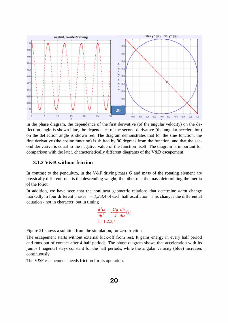
The oscillation in this approximation has a purely harmonic, sinusoidal pattern (left graph of fig-ure 21). The phase diagram (right graph, circle and line at -45 degrees) corresponds to a central section for small arcs of the above diagram (figure 19) for general arcs.
11 The graph shows the numeric integration of the differential equation. The simulation program Oscillators is part of
the book „Learning and Teaching Math with Simulations“ , the digital version of which can be loaded cost free from the author’s page http://www.physik.uni-wuerzburg.de/~roess/MatheUndSimulation.htm
ansatz - : an initial estimate of the solution to a mathematical or technical problem that is used to guide work to a more precise answer
20
In the phase diagram, the dependence of the first derivative (of the angular velocity) on the de-flection angle is shown blue, the dependence of the second derivative (the angular acceleration) on the deflection angle is shown red. The diagram demonstrates that for the sine function, the first derivative (the cosine function) is shifted by 90 degrees from the function, and that the sec-ond derivative is equal to the negative value of the function itself. The diagram is important for comparison with the later, characteristically different diagrams of the V&B escapement.
3.1.2 V&B without friction
In contrast to the pendulum, in the V&F driving mass G and mass of the rotating element are physically different; one is the descending weight, the other one the mass determining the inertia of the foliot
In addition, we have seen that the nonlinear geometric relations that determine dh/dt change markedly in four different phases i = 1,2,3,4 of each half oscillation. This changes the differential equation - not in character, but in timing
2
2- ( )
i = 1,2,3,4
d Gg dhi
J ddt
Figure 21 shows a solution from the simulation, for zero friction
The escapement starts without external kick-off from rest. It gains energy in every half period and runs out of contact after 4 half periods. The phase diagram shows that acceleration with its jumps (magenta) stays constant for the half periods, while the angular velocity (blue) increases continuously.
The V&F escapements needs friction for its operation.

21
3.2. Including friction
It is quite straightforward to include the influence of friction, by adding the friction term, propor-tional to the first derivative (the angular speed), into the differential equation
3.2.1 Pendulum with friction
Friction (as by air resistance) is proportional to the speed of the bob which is L*d/dt
2
22 cos
d g dRL
L dtdt
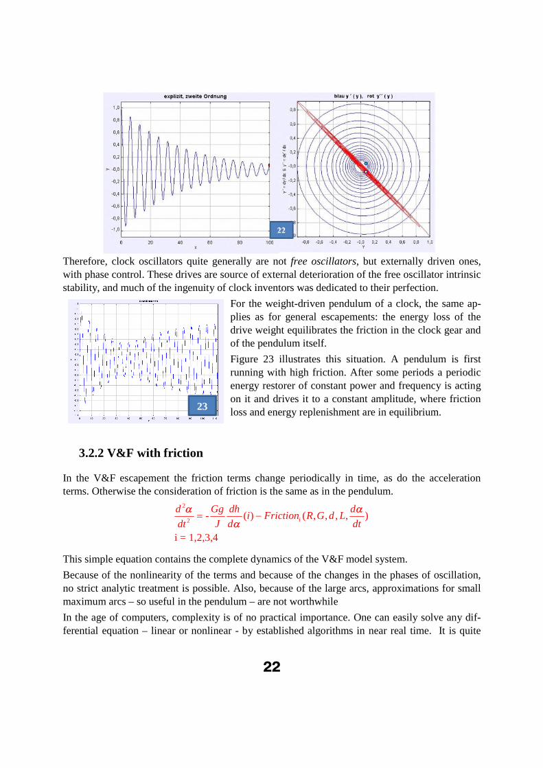
With friction in the pendulum equation, we obtain a periodic function whose amplitude decreases exponentially with time, while the momentary frequency increases (see figure 22 for amplitude and phase).
For a free pendulum friction in air is low, so it takes a long time until the amplitude drops signifi-cantly. The frequency changes become very small for small maximum arcs.
Any clock escapement suffers some kind of friction. To arrive at a stable amplitude the energy lost by friction must by restored, continuously, or as in most clocks, with a periodic pulse at the proper phase of oscillation.
22
23
Therefore, clock oscillators quite generally are not free oscillators, but externally driven ones, with phase control. These drives are source of external deterioration of the free oscillator intrinsic stability, and much of the ingenuity of clock inventors was dedicated to their perfection.
For the weight-driven pendulum of a clock, the same ap-plies as for general escapements: the energy loss of the drive weight equilibrates the friction in the clock gear and of the pendulum itself.
Figure 23 illustrates this situation. A pendulum is first running with high friction. After some periods a periodic energy restorer of constant power and frequency is acting on it and drives it to a constant amplitude, where friction loss and energy replenishment are in equilibrium.
3.2.2 V&F with friction
In the V&F escapement the friction terms change periodically in time, as do the acceleration terms. Otherwise the consideration of friction is the same as in the pendulum.
2
2- ( ) ( , , , , )
i = 1,2,3,4
i
d Gg dh di Friction R G d L
J d dtdt
This simple equation contains the complete dynamics of the V&F model system.
Because of the nonlinearity of the terms and because of the changes in the phases of oscillation, no strict analytic treatment is possible. Also, because of the large arcs, approximations for small maximum arcs – so useful in the pendulum – are not worthwhile
In the age of computers, complexity is of no practical importance. One can easily solve any dif-ferential equation – linear or nonlinear - by established algorithms in near real time. It is quite

23
convincing how the classic Runge-Kutta-4 algorithm chosen for the simulation masters the jumps in the acceleration terms of the V&F! (see the right graph in fig. 24)
In the next chapter on the Simulation we will describe in detail specific results obtained with it.
Figure 24 closes this chapter with the oscillation pattern and phase diagram of a V&F in a typical
parameter setup (equilibrium angle ~800, d = 0.5, = 900).
The oscillation starts from zero at rest. After some oscillations its achieves its equilibrium level between drive and friction. For comparison a sinusoidal of constant frequency and amplitude is overlaid in blue color.
The red curve of acceleration in the right graph looks rather bizarre with its jumps and loops. It is to be compared with the line at -45 degrees for the pendulum. For better visualization the calcula-tion points are linked by a line. In the calculation there are real jumps. The blue angular speed curve starts in the center (zero speed) and circles in to the equilibrium state. The asymmetry is well observable: in the two half-periods the interaction points jump at either right or left of the zero position
.
Considering, that in the phase diagram the closed blue curve is the first derivative, and the red one the second derivative of the quasi-sinusoidal pattern of arc over time in the left graph, the ex-ample beautifully demonstrates the effect of smoothing by integration.
The differential equation can easily be extended to also include the inertia of crown wheel and bottom wheel, and the dynamic energy of the weight in its up and down oscillation, too. Their contribution to the V&F behavior is small and not essential for the general understanding of its function.
24

24
4 Simulation of the V&F Escapement
4.1 Method
For the evaluation of the differential equation of the V&F escapement a simulation was pro-grammed with the EJS (Easy Java Simulation)12-program of Francisco Esquembre. When run on a computer, its results can be presented in multiple windows on the screen simultaneously:
oscillation angle, angular speed and acceleration as function of time,
associated phase diagrams,
geometry of the oscillating escapement in motion,
friction at the pallets as function of angle and time,
weight oscillation as function of angle and time.
In addition to this, characteristic time points and numerical values are output in a data table, from which time dependent frequency, amplitude maxima and frictional influence can be read with a degree of accuracy in the 1 % range.
When marking any point in the windows with the mouse, its coordinates show up at the lower left corner of the window with high resolution.
Parameters, which can be changed by means of sliders, or set more precisely by input fields, are:
Pallet angle (gamma)
Verge distance d/L (depth of engagement)
Initial value of the oscillation arc
Drive A (Impact of driving weight at the crown wheel tooth / inertia of verge and foliot)
Driving Weight G
Coefficient of friction R
Time step of calculation
Maximum calculation time
The calculation can proceed continuously or in single steps.
Several computer-runs with different parameters can be superimposed.
All windows are equipped with switches for start/stop, step and return, to allow active operation with full screen windows.
When all windows are open, the work load of increasing stored data slows down the graphic presentation of the calculation at the screen. There is a selection window in which only relevant windows can be selected to be open.
12 EJS (Easy Java Simulation) is a cost free, comfortable program developed by Francisco Esquembre for the devel-
opment of JAVA simulations. http://www.um.es/fem/EjsWiki/pmwiki.php. With it one can realize simple or com-plex simulations and their visualization on the PC screen without deep JAVA programming knowledge.

25
The result in hidden windows can be selected to show up at any time. Irrelevant windows can al-so be closed permanently for a run to speed up calculation. They will be reopened at the next start of the program.
In the main window, a sine function, adjustable in frequency, amplitude and phase, can be super-imposed on the computation results for the arc (activate the sine button) to compare the V&F os-cillation with this standard oscillation pattern.
The integral of friction over a period of oscillation can be selected to show in some windows by a switch.
A useful strategy to follow in experimenting with the program is:
Start with a limit setup without drop and study the influence of changes in parameters.
Add drop to compare its influence in real clocks.
The parameter setting inputs are concatenated in such a way that only working setups can be real-ized. If for example, at given engagement a pallet angle is selected that would lead to clamping,
the program will automatically reset to the limit angle.
Figure 25 shows how the windows should appear at your screen. Now individual windows will be described.
25

26
4.2 Windows of the simulation
4.2.1 Main Window
The main window in figure 25 carries control elements for the parameters, which can be changed
by sliders or by writing numbers into the input fields. To activate changes in the input fields, please press the ENTER key of the keyboard. Nonvalid entries will be signaled by field color.
Range and resolution of parameters via sliders is limited. By means of the input fields you can choose precise, arbitrary values, even beyond of the range of the sliders.
The plotting table shows arc over time. An arrow at the leading edge of the plot signals direction and value of acceleration.
Blue horizontal lines mark where the escapement loses contact. Cyan- colored lines mark = /2, where leverage jumps from L to d and vice versa. Green lines mark positions of tooth change.
:2
cos( ) cos( ) ; cos arcuscosinus2 2
: cos( ) cos( )2 2
change flank to tip (green line)
tooth change (cyan line)
loss of contact (thick blue line)
d da a
L L
d da
L L
∓
∓
∓
With the checkbox show sine a sinusoidal of constant frequency and amplitude can be overlaid. Its amplitude, frequency and phase are adjusted by three sliders.
The checkbox F_integral releases the integral of friction over one half period.
It is quite useful to superimpose several runs with different parameters. Using the option box line avoids confusing return lines. Deactivating line, just individual points of calculation are shown.
For high precision the calculation step should be so low, that even lower values give no signifi-cantly different result.
In the function field the mathematical terms for angular acceleration in the changing phases of os-cillation appear for information.
The initial arc can be set by slider or number field, yet more quickly by drawing the starting dot with the cursor.
Tooth distance is not a variable parameter, as is the pallet length, which is set at L = 1. Tooth spac-ing will automatically adjust itself to the other parameters to form a “Limit” setup, without drop.
The calculation time can be changed in the tmax input field
4.2.3 Window Selection
The selection window carries with a number of check boxes, that select which other windows are shown. At start only the main window, the escapement window and the selection window are acti-
27
vated. This restriction allows close to real time speed of the display. Yet all contents of inactive windows are calculated, and can be visualized later by their selection.
4.2.4 Window Escapement
Details of this graph have been used and described before. For close inspection of critical points, as the escape or change of a tooth it is useful to run the calculation close to this point at normal speed, stop the automatic run and proceed from there with the step switch. When the window is blown up to screen size in between, this can be done with high precision.
4.2.5 Windows Phase diagram and Derivatives
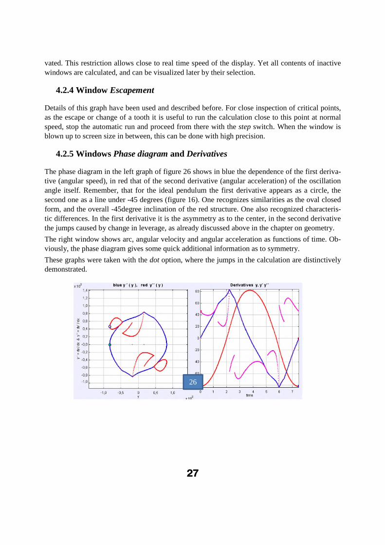
The phase diagram in the left graph of figure 26 shows in blue the dependence of the first deriva-tive (angular speed), in red that of the second derivative (angular acceleration) of the oscillation angle itself. Remember, that for the ideal pendulum the first derivative appears as a circle, the second one as a line under -45 degrees (figure 16). One recognizes similarities as the oval closed form, and the overall -45degree inclination of the red structure. One also recognized characteris-tic differences. In the first derivative it is the asymmetry as to the center, in the second derivative the jumps caused by change in leverage, as already discussed above in the chapter on geometry.
The right window shows arc, angular velocity and angular acceleration as functions of time. Ob-viously, the phase diagram gives some quick additional information as to symmetry.
These graphs were taken with the dot option, where the jumps in the calculation are distinctively demonstrated.
26

28
4.2.6 Windows Friction as function of angle and Friction as function of time
The variation of friction during the oscillation is calculated as a function of foliot angle, and of time. Both are shown in figure 27 for a half period.
The side lobes characterize the range where the pallet rim is driven by the tooth flank.
In between, the pallet plane is driven by the tooth tip. Observing the dependance on angle one is inclined to underestimate the first range. The dependance on time shows why: because of the low angular speed near the return points, the escapement stays in the lobes for the greater part of time, yet not of angle.
4.2.7 Windows G-Oscillation as function of angle and as function of time
In the chapter on geometry we have stressed the importance of the oscillation of the driving weight as part of the overall oscillating system in the V&F. Therefore, there are two windows of this movement, shown for a half period in figure 24. The left graph shows the movement at the
26
27

29
28
29
rim of the crown wheel (see figure 3) as a function of the angle . Here one dramatically sees the loss in height at tooth change (on the return path along the line). Yet this is not what one observes when watching the weight. Here one looks at the time scale of the right graph, and now the oscil-lation is clearly demonstrated.
4.2.8 Window Data Table
The data table of figure 28 stores data at specific points in time.
The point in time is determined when the first deriv-ative of the angle is near zero, that is at a peak of the
oscillation. The condition is |d/dt| < 0.3*step. The
first column shows counting index, the second time. The third approximates the momentary period as twice the difference of consecutive peak times. The fourth shows the maximum arc, the fifth the friction integral per period.
This table was taken for an oscillation starting at a very small angle of 1 degree, and developing to-wards its equilibrium amplitude of about 85 degrees, and its equilibrium period of 7.76 seconds.
The right column shows how more and more fric-tion energy is absorbed with increasing angle per
period, till an equilibrium is achieved. The friction integral is calculated for a full peri-
od; therefore, every second row is empty.
Figure 29 shows this approach to equilibri-um as a function of time, with data taken from the data table. Period and arc approach their equilibrium exponentially (for compar-ison, see the mathematical exponential ap-proach in red).As the timing criteria is near the calculation resolution, it can happen that the trigger acts more than once for a peak; such spurious data should be suppressed when working with the data table.
Be reminded that precise values can be read in any plotting panel by marking a point with the mouse. Its coordinates are then shown in the lower left corner of the panel. This is most effective when the window is blown up to screen size.
30
4.3 Opening and experimenting with the simulation; possibility of changing the algorithm
The abundance of possibilities and phenomena can only be exploited by experimenting with the simulation itself. We will describe some useful examples in the next chapter.
To use the simulation, the Java Runtime Environment (JRE) program, must be installed on the computer. which can be downloaded free of charge. Your personal computer could be configured to block all executable Java files for security reasons. In this case you would have to release the setting for the simulation file.
Simply open the EJS.jar file. There is no need of installation.
The file is protected against unintentional manipulation. Whatever you do with the opened win-dows would normally be lost after closing the file. Yet you can create a new jar-file that pre-serves the present status. Just go into a window, open the context menu with the right mouse pad and select the option
Input output/status - set default state to jar
A new simulation file will be created, while the original file stays unchanged.
The same context menu offers valuable additional options, among them a nice and quick snapshot tool. It was used for many of the graphs in this text.
Finally, the context menu opens a way to delve deeply into the simulation algorithm, to analyze, change or develop it further. Choose
Open EJS Model and store all proposed files.
Load the EJS development program for free from http://www.um.es/fem/EjsWiki/
From the EJS- console you can then open the simulation and work inside of it. The WIKI helps to understand the procedure.
If the simulation gets stuck for any reason, close it and reopen it again.
5 Selected Results of the Simulation Calculations
The following pictures are snapshots from the simulation, which demonstrate how to experiment with this computational model.
5.1 Start with varying friction coefficient
Above it was shown that the V&B runs out of engagement without friction. Now it is investigated
how runaway or equilibrium arc depend on the friction coefficient, for otherwise constant terms
( = 900, d = 0.5, A = 1, G =1, negligible drop, step = 0.02 s). Friction coefficients for consecu-
tive runs are 1, 0.8 and 0.6.
The runs of figure 30 start at zero angle with zero angular velocity. For R ≥0.8 the arc stabilizes; at R = 0.6 the escapement loses contact after 5 half periods.
31
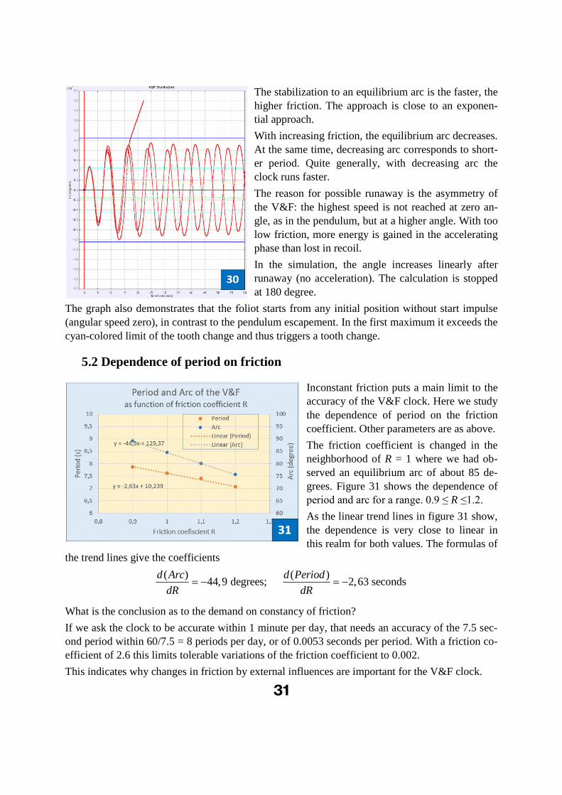
The stabilization to an equilibrium arc is the faster, the higher friction. The approach is close to an exponen-tial approach.
With increasing friction, the equilibrium arc decreases. At the same time, decreasing arc corresponds to short-er period. Quite generally, with decreasing arc the clock runs faster.
The reason for possible runaway is the asymmetry of the V&F: the highest speed is not reached at zero an-gle, as in the pendulum, but at a higher angle. With too low friction, more energy is gained in the accelerating phase than lost in recoil.
In the simulation, the angle increases linearly after runaway (no acceleration). The calculation is stopped at 180 degree.
The graph also demonstrates that the foliot starts from any initial position without start impulse (angular speed zero), in contrast to the pendulum escapement. In the first maximum it exceeds the cyan-colored limit of the tooth change and thus triggers a tooth change.
5.2 Dependence of period on friction
Inconstant friction puts a main limit to the accuracy of the V&F clock. Here we study
the dependence of period on the friction coefficient. Other parameters are as above.
The friction coefficient is changed in the neighborhood of R = 1 where we had ob-served an equilibrium arc of about 85 de-grees. Figure 31 shows the dependence of period and arc for a range. 0.9 ≤ R ≤1.2.
As the linear trend lines in figure 31 show, the dependence is very close to linear in this realm for both values. The formulas of
the trend lines give the coefficients
( ) ( )44,9 degrees; 2,63 seconds
d Arc d Period
dR dR
What is the conclusion as to the demand on constancy of friction?
If we ask the clock to be accurate within 1 minute per day, that needs an accuracy of the 7.5 sec-ond period within 60/7.5 = 8 periods per day, or of 0.0053 seconds per period. With a friction co-efficient of 2.6 this limits tolerable variations of the friction coefficient to 0.002.
This indicates why changes in friction by external influences are important for the V&F clock.

32
5.3 Dependence on depth of engagement
Period and Arc depend strongly on how deep the pallet dives into the crown wheel tooth flank. The relevant measure for this is the engagement d/L. We call the engagement deep when d/L is close to its minimum value (0 < d/L < ~0.5), and as shallow when it is closer to its maximum val-ue (~0.5 < d/L < 1).
We study the dependence on change in engagement depth in a similar way as above. Parameters are similar, with R = 1, and d/L varying from 0.45 to 0.55. The oscillation in figure 32 starts near the respective equilibrium arc for d = 0.5.
Period and amplitude decrease with increasing d/L (decreasing depth of engagement). The clock runs slower and with increasing arc for deeper engagement (at negligible drop).
The dependence on d/L is close to linear in the considered realm.
Both coefficients are even larger than those of the friction dependence. As a consequence, in V&F clocks any looseness along the axis of the crown wheel should be avoided to ensure stable distance of the crown wheel tooth tips to the verge axis. Washers or an adjustable screw can en-sure that and are observed in old clocks.
5.4 Dependence on relative Drive
For the next virtual experiment, the relative drive A = G/J, the ratio of drive weight G to Inertia Jof the foliot, is varied. Parameters are as before; d = 0.5.
With increasing A (more drive weight at constant inertia or less inertia at constant drive weight) the period becomes shorter (the clock runs faster), while the amplitude increases.
The dependence is still close to linear. The coefficients now run in different directions. While they are quite large, and comparable in order of magnitude to that on friction, they are less critical in clocks.
32

33
As mentioned above, variations of the weight by the added weight of the rope during descend can be easily compensated.
Some authors claim a variation of the inertia by elongation of the foliot with temperature, which should make the clock runs slower at higher temperature, according to the graph above (this ef-fect makes also the pendulum run slower at higher temperature). In the V&F the effect is negligi-ble, as the following estimate shows:
6
6 3
distance of foliot cursors from verge axis: 500 mm
thermal expansion coefficient of iron: 11.8*10 per degree
500*11.8*10 =5.9*10 / degree
LK
L
L mm K
.
2
5
5
2
2 2 *10 / degree
( ) 2.4 5*10 / degree
LJ B
J LC
J L
Period AA Period s C
Period A
This compares to the value of 0.0053 seconds per period calculated above for an accuracy of 1 minute per day. Thermal expansion of the oscillating parts is only important at an accuracy of seconds per day, as it is indeed with fine pendulum clocks.
5.5 Dependence on pallet angle
The next experiment of figure 34 determines the dependence on pallet angle. Settings are as be-fore, with d = 0,5 and A = 1.
With increasing pallet angle period becomes smaller, the clock runs faster, and amplitude de-creases.
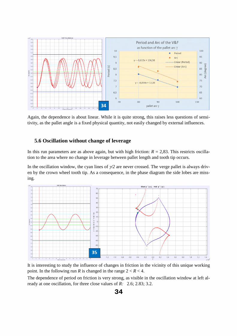
34
Again, the dependence is about linear. While it is quite strong, this raises less questions of sensi-tivity, as the pallet angle is a fixed physical quantity, not easily changed by external influences.
5.6 Oscillation without change of leverage
In this run parameters are as above again, but with high friction: R = 2,83. This restricts oscilla-tion to the area where no change in leverage between pallet length and tooth tip occurs.
In the oscillation window, the cyan lines of /2 are never crossed. The verge pallet is always driv-
en by the crown wheel tooth tip. As a consequence, in the phase diagram the side lobes are miss-ing.
It is interesting to study the influence of changes in friction in the vicinity of this unique working point. In the following run R is changed in the range 2 < R < 4.
The dependence of period on friction is very strong, as visible in the oscillation window at left al-ready at one oscillation, for three close values of R: 2.6; 2.83; 3.2.
35
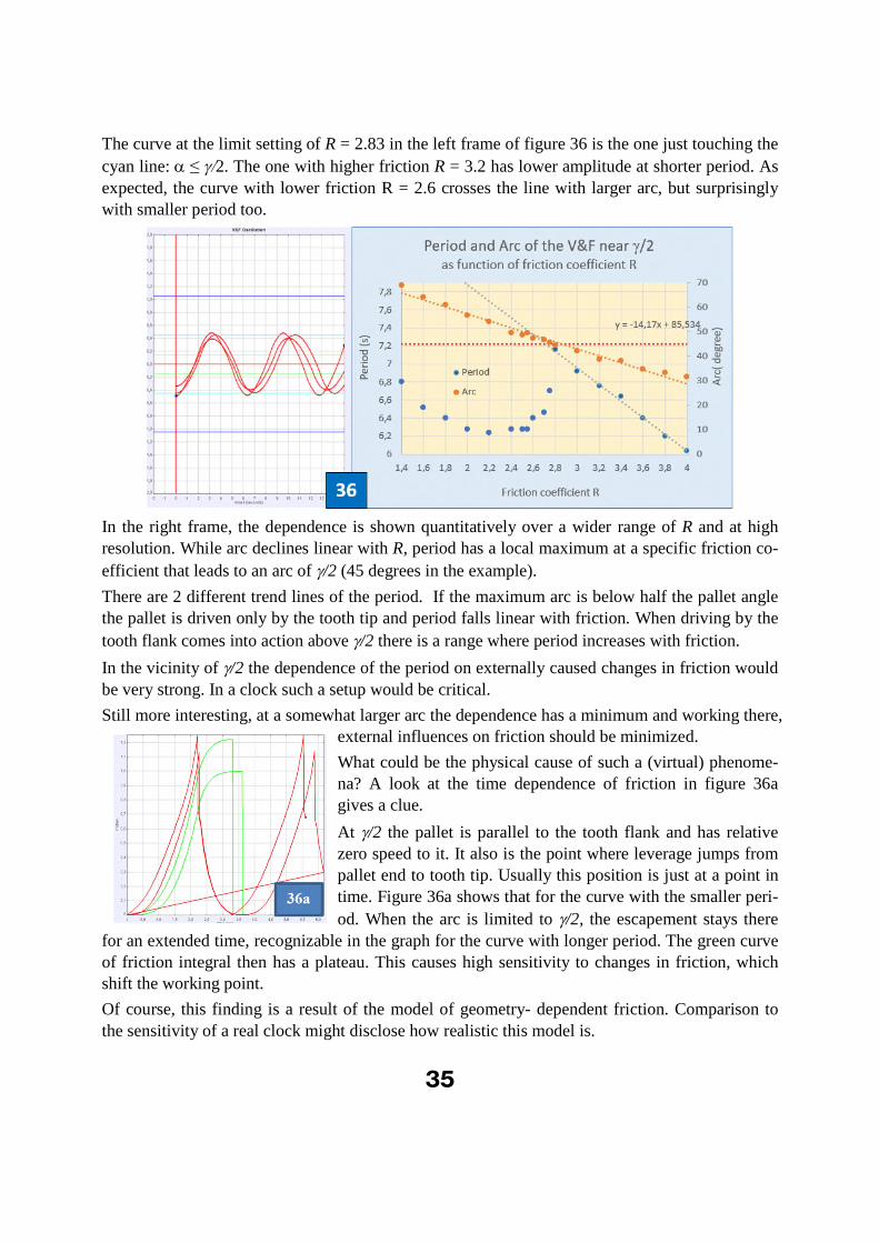
The curve at the limit setting of R = 2.83 in the left frame of figure 36 is the one just touching the
cyan line: ≤2. The one with higher friction R = 3.2 has lower amplitude at shorter period. As
expected, the curve with lower friction R = 2.6 crosses the line with larger arc, but surprisingly with smaller period too.
In the right frame, the dependence is shown quantitatively over a wider range of R and at high resolution. While arc declines linear with R, period has a local maximum at a specific friction co-
efficient that leads to an arc of /2 (45 degrees in the example).
There are 2 different trend lines of the period. If the maximum arc is below half the pallet angle the pallet is driven only by the tooth tip and period falls linear with friction. When driving by the
tooth flank comes into action above /2 there is a range where period increases with friction.
In the vicinity of /2 the dependence of the period on externally caused changes in friction would
be very strong. In a clock such a setup would be critical.
Still more interesting, at a somewhat larger arc the dependence has a minimum and working there, external influences on friction should be minimized.
What could be the physical cause of such a (virtual) phenome-na? A look at the time dependence of friction in figure 36a gives a clue.
At /2 the pallet is parallel to the tooth flank and has relative zero speed to it. It also is the point where leverage jumps from pallet end to tooth tip. Usually this position is just at a point in time. Figure 36a shows that for the curve with the smaller peri-
od. When the arc is limited to /2, the escapement stays there
for an extended time, recognizable in the graph for the curve with longer period. The green curve of friction integral then has a plateau. This causes high sensitivity to changes in friction, which shift the working point.
Of course, this finding is a result of the model of geometry- dependent friction. Comparison to
the sensitivity of a real clock might disclose how realistic this model is.

36
5.7 Dependence on drop
The effect of drop is best visualized in the phase diagram. Figure 37 compares those of oscilla-tions without and with drop. Except of drop, parameters are equal for all graphs.
The left graph shows an oscillation with constant amplitude for zero drop. The blue curve of an-gular speed is closed: the oscillation amplitude is constant.
Discrete calculation points of angular acceleration are joined in the graphs by red lines for better recognition. In the calculation itself jumps in acceleration are realized.
In the second graph 20% drop is added (20% of the tooth distance). One recognizes the sharp pulses in deceleration at drop, accompanied by some mild kink in the angular speed. The angular speed curve is no longer closed: the oscillation amplitude decreases.
To compensate for this damping, in the third graph the friction coefficient is reduced from R = 1.0 to R = 0.7. Now the oscillation amplitude is constant again.
For this setting, a drop of 20 % is equivalent to an increase of the friction coeffi-cient of about 30%.
Figure 38 shows an enlarged view of the drop jump (red dots acceleration). In the angular speed (blue dots) it results in a short period of enhanced decrease.
5.8 Parameter sets for tuning the V&F to specific periods
Obviously, the V&F clock should run with the same period for different sets of parameters. To
limit the variety, we look for sets with constant drive weight G = 1, pallet angle = 900 and en-
gagement d = 0.5 (these are fixed values in a real clock). Relative drive A and (equilibrium) arc are investigated in dependence of the friction coefficient R, with the goal to obtain the same peri-od (a value of 7.8 seconds was the chosen target). With constant weight G a change in A means an inverse change in the Inertia of the foliot.
37
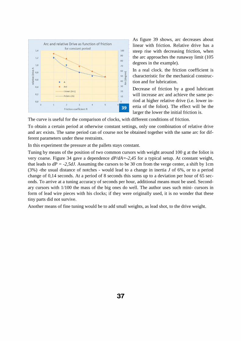
As figure 39 shows, arc decreases about linear with friction. Relative drive has a steep rise with decreasing friction, when the arc approaches the runaway limit (105 degrees in the example).
In a real clock. the friction coefficient is characteristic for the mechanical construc-
tion and for lubrication.
Decrease of friction by a good lubricant will increase arc and achieve the same pe-riod at higher relative drive (i.e. lower in-ertia of the foliot). The effect will be the larger the lower the initial friction is.
The curve is useful for the comparison of clocks, with different conditions of friction.
To obtain a certain period at otherwise constant settings, only one combination of relative drive and arc exists. The same period can of course not be obtained together with the same arc for dif-ferent parameters under these restraints.
In this experiment the pressure at the pallets stays constant.
Tuning by means of the position of two common cursors with weight around 100 g at the foliot is very coarse. Figure 34 gave a dependence dP/dA=-2,45 for a typical setup. At constant weight, that leads to dP = -2,5dJ. Assuming the cursors to be 30 cm from the verge center, a shift by 1cm (3%) -the usual distance of notches - would lead to a change in inertia J of 6%, or to a period change of 0,14 seconds. At a period of 8 seconds this sums up to a deviation per hour of 65 sec-onds. To arrive at a tuning accuracy of seconds per hour, additional means must be used. Second-ary cursors with 1/100 the mass of the big ones do well. The author uses such mini- cursors in form of lead wire pieces with his clocks; if they were originally used, it is no wonder that these tiny parts did not survive.
Another means of fine tuning would be to add small weights, as lead shot, to the drive weight.
38
7 Miscellaneous
7.1 Verge Theories
Quite a number of highly respected horologists have spent time and effort treating the theory of the verge escapement in the past – no wonder, as it is at the origin of all mechanical clocks.
The general problem in such a theory is how to find and present solutions for a very nonlinear system. In the present paper computer technique is utilized to achieve the solution by a numerical algorithm, visualizing results in a real time, interactive PC simulation program. With this proce-dure, complexity is no longer a hindrance and it pays to analyze the geometric relations in full de-tail. This road was not open in the further past, and authors had to struggle with simplified mod-els and approximations to arrive at analytic results.
The more it is to admire, how deeply some dug into the details of the escapement.
Léopold Defossez «Théorie Générale de L’Horlogerie « Volume 2 – 1950 – Page 133
describes action and counteraction between tooth and pallet and recognizes that friction in it is very high. He misses the change in leverage between tooth flank and tooth tip: “they are sharp, they act only by their tips”. Like some other authors, he draws this conclusion from drawings of watch verges with highly undercut crown wheel teeth, where this is approximately true, but gen-eralizes this impression.
Von Bertele “Precision timekeeping in the Huygens era” Horological Journal, Vol. XCV No.1143 December 1953,
is an often-quoted paper that is still worthwhile studying. He describes at page 805 the drawback
of combining oscillation, counting and energy restoration in a single element, the verge, and stresses the high friction in it. He speculates on the hypothetical possibility of using twisted sus-pension threads to give a gravitational lift to the foliot, and so achieve a true oscillator with ei-genfrequency. Yet he seems not to have recognized that this counterpart is already achieved in the weight oscillation, and hence disqualifies the escapement as a true oscillator. This could to be the source of many later statements of this type.
Andronov Khaikin “Theory of oscillators” by A.A. Andronov, A.A. Vitt, and S.E. Khaikin 1987 Dover Edition reprint of 1966 Pergamon Press Ltd.
quite generally treats models of oscillatory systems including loss, with extensive use of differen-tial analysis. In a chapter on clock escapements with recoil he introduces phase plane diagrams to
illustrate the asymmetry, which is so pronounced in the diagrams of the V&F.
Fred Powell “On the dynamics, geometry and energy flow of the verge escapement” 1981, Sim-monds Precision Press Vergennes, Vermont, USA
tackles the dynamic problem by means of a differential equation, that describes a damped oscilla-tor. He derives from it a great wealth of approximate analytic formulas. As his equation does not include the dynamic equilibrium with the weight, it is a first order approximation to the dynamics.
Roupnoy, Bernstein, Nersesovz, Haddanoz and Chellaboina “Limit cycle analysis of the verge and foliot clock escapement using impulsive differential equations and Poincare´ maps” Interna-
39
tional Journal of Control ISSN 0020–7179 print/ISSN 1366–5820 online # 2003 Taylor & Fran-cis Ltd http://www.tandf.co.uk/journals DOI: 10.1080/00207170310001632412
present a tremendously complex mathematical treatment of the V&G escapement. Their model is based on the impulse at drop being the active agent, while “the verge spins freely at all times ex-cept at the instant a collision takes place”. Unfortunately, this is not correct, and the graphs of motion in zigzag-manner have little resemblance to the smooth oscillations observed in reality.
P. Hoyng “Dynamics of the verge and foliot clock escapement” Cornell University Library, sub-mitted arXiv:1604.06681v1 [physics.class-ph] 22 Apr 2016
in a recent paper tries to treat the dynamics of the verge by a differential equation. The author
starts with the incomplete “ansatz” “The swing angle obeys the same differential equation as
that of a pendulum, except that there is no restoring gravity torque: ( )a m That is the
differential equation of a damped oscillator proposed for the verge by Powell 1981. It lacks the oscillatory contribution of the drive weight and does not describe the dynamics of the escapement. This author quotes a number of additional authors that the interested reader may look up.
7.2 Why is it not possible to observe “free oscillation” of the Verge and Foliot escapement?
There is quite a hot discussion between horologists if the V&F escapement is a true oscillator or not. Beyond traditional prejudices one can argue that nobody has yet seen such an escapement in free oscillation – even if strongly damped – something easily realized with a pendulum escape-ment.
In the foliot + weight- oscillator, a number of essential elements of a clock are ingeniously com-bined mechanically by one single part, the verge:
Two physically separated oscillator elements: weight and foliot
Energy restorer, driven by the weight
Counter and torque reverser
For demonstration of free oscillation, the oscillator must be free of the energy restorer. But this is not possible in the V&F, as the weight takes part in both functions. This is the deeper reason why the V&F escapement seems to lack an independent oscillator.
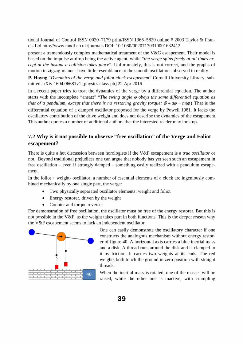
One can easily demonstrate the oscillatory character if one constructs the analogous mechanism without energy restor-er of figure 40. A horizontal axis carries a blue inertial mass and a disk. A thread runs around the disk and is clamped to it by friction. It carries two weights at its ends. The red weights both touch the ground in zero position with straight threads.
When the inertial mass is rotated, one of the masses will be raised, while the other one is inactive, with crumpling
40
thread. The oscillator exchanges gravitational and rotational energy as the V&F does. Once set in motion it will perform a damped oscillation for quite a number of periods. It can be easily built from workshop scrap.
Two weights are necessary to realize the reversal of torque that the verge elegantly manages by the change of pallets.
7.3 Good and bad gear ratios
In a V&F clock small defects in the parts cannot be avoided: orientation of wheels to their axis, differences in tooth heights or separation, and in their wear. All of them can be observed in the beat frequencies and in the arc.
These defects are periodic and average out in one full revolution of the respective wheel. The hour (bottom) wheel sets a minimum limit of 1 hour for averaging out its defects. To have the
crown wheel average within the same time, its revolution, and hence the gear ratio between both wheels, should be an integer multiple of the bottom wheel revolution. If it is not an integer, it will take more than one hour to have all parts of the clock repositioned.
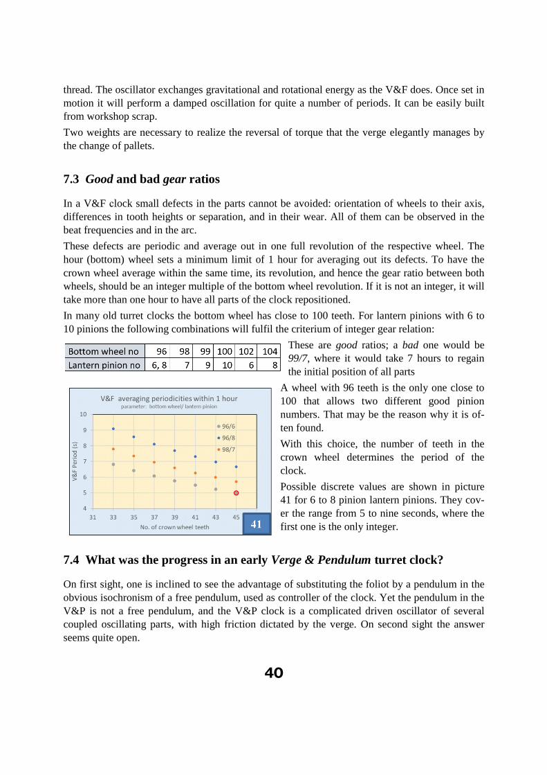
In many old turret clocks the bottom wheel has close to 100 teeth. For lantern pinions with 6 to 10 pinions the following combinations will fulfil the criterium of integer gear relation:
These are good ratios; a bad one would be 99/7, where it would take 7 hours to regain the initial position of all parts
A wheel with 96 teeth is the only one close to 100 that allows two different good pinion numbers. That may be the reason why it is of-ten found.
With this choice, the number of teeth in the crown wheel determines the period of the clock.
Possible discrete values are shown in picture 41 for 6 to 8 pinion lantern pinions. They cov-er the range from 5 to nine seconds, where the first one is the only integer.
7.4 What was the progress in an early Verge & Pendulum turret clock?
On first sight, one is inclined to see the advantage of substituting the foliot by a pendulum in the obvious isochronism of a free pendulum, used as controller of the clock. Yet the pendulum in the V&P is not a free pendulum, and the V&P clock is a complicated driven oscillator of several coupled oscillating parts, with high friction dictated by the verge. On second sight the answer seems quite open.

41
In the early substitutions a short, light pendulum was rigidly attached to the now horizontally ori-ented verge. The bob with its rod substituted the inertia of the foliot and added to the gravitation-al mass in motion. The system now had 3 parts oscillating:
Inertial mass
Gravitational mass of the bob plus pendulum rod
Gravitational mass of the drive weight
In a perfect arrangement that may have increased the intrinsic accuracy, which already was quite good in the V&F (see recent measurement results in the attachment). Yet the sensitivity of the verge/pallet interaction to external influence remained the same. This, not the intrinsic oscillator
reproducibility determines the practical accuracy of the early verge turret clock. So, one should consider other aspects of the change, too:
There is at third wheel in the train to adjust to the high frequency of a short pendulum,
which reduces pressure at the pallets at given drive weight.
The arc is limited to less than half the pallet angle, which simplifies the geometric condi-
tions of torque and friction.
There is no gear with its easily influenced friction between the rotational and the greater
part of the gravitational mass movement path.
The air resistance of rod and bob is smaller than that of the foliot with its cursors; hence
the influence of changes in air pressure will be smaller.
Etc., etc.
It seems worthwhile to study these questions both theoretically and experimentally, to better un-derstand an important step forward in the history of horology.
Finis
42
Addendum:
Recent Measurement Results on a reconstructed 1478 V&F Clock
The author owns a V&F clock dated 1478, that had been transformed to Verge and Pendulum. It was reconstructed to verge and foliot escapement, equipped with a Huygens perpetual weight lift and with modern sensors for foliot and hour wheel period.
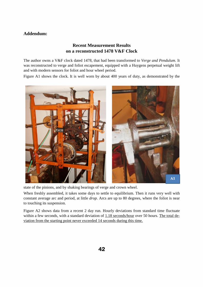
Figure A1 shows the clock. It is well worn by about 400 years of duty, as demonstrated by the
state of the pinions, and by shaking bearings of verge and crown wheel.
When freshly assembled, it takes some days to settle to equilibrium. Then it runs very well with constant average arc and period, at little drop. Arcs are up to 80 degrees, where the foliot is near to touching its suspension.
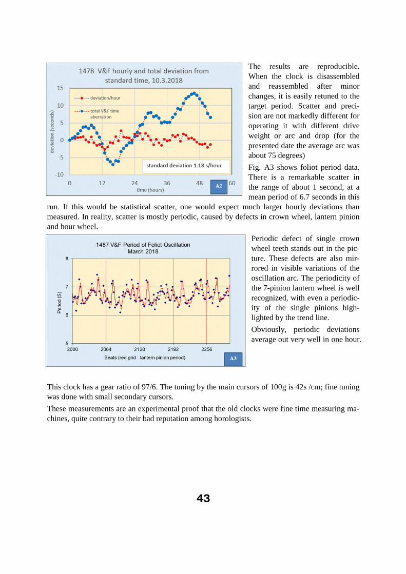
Figure A2 shows data from a recent 2 day run. Hourly deviations from standard time fluctuate within a few seconds, with a standard deviation of 1.18 seconds/hour over 50 hours. The total de-viation from the starting point never exceeded 14 seconds during this time.
43
The results are reproducible. When the clock is disassembled and reassembled after minor changes, it is easily retuned to the target period. Scatter and preci-sion are not markedly different for operating it with different drive
weight or arc and drop (for the presented date the average arc was about 75 degrees)
Fig. A3 shows foliot period data. There is a remarkable scatter in the range of about 1 second, at a mean period of 6.7 seconds in this
run. If this would be statistical scatter, one would expect much larger hourly deviations than measured. In reality, scatter is mostly periodic, caused by defects in crown wheel, lantern pinion and hour wheel.
Periodic defect of single crown wheel teeth stands out in the pic-ture. These defects are also mir-rored in visible variations of the oscillation arc. The periodicity of the 7-pinion lantern wheel is well recognized, with even a periodic-ity of the single pinions high-lighted by the trend line.
Obviously, periodic deviations average out very well in one hour.
This clock has a gear ratio of 97/6. The tuning by the main cursors of 100g is 42s /cm; fine tuning was done with small secondary cursors.
These measurements are an experimental proof that the old clocks were fine time measuring ma-chines, quite contrary to their bad reputation among horologists.