theory for passive mode-locking in semiconductor …theory for passive mode-locking in semiconductor...
TRANSCRIPT
Theory for passive mode-locking in semiconductor laserstructures including the effects of self-phase modulation,dispersion and pulse collisionsCitation for published version (APA):Koumans, R. G. M. P., & Roijen, van, R. (1996). Theory for passive mode-locking in semiconductor laserstructures including the effects of self-phase modulation, dispersion and pulse collisions. IEEE Journal ofQuantum Electronics, 32(3), 478-492. https://doi.org/10.1109/3.485400
DOI:10.1109/3.485400
Document status and date:Published: 01/01/1996
Document Version:Publisher’s PDF, also known as Version of Record (includes final page, issue and volume numbers)
Please check the document version of this publication:
• A submitted manuscript is the version of the article upon submission and before peer-review. There can beimportant differences between the submitted version and the official published version of record. Peopleinterested in the research are advised to contact the author for the final version of the publication, or visit theDOI to the publisher's website.• The final author version and the galley proof are versions of the publication after peer review.• The final published version features the final layout of the paper including the volume, issue and pagenumbers.Link to publication
General rightsCopyright and moral rights for the publications made accessible in the public portal are retained by the authors and/or other copyright ownersand it is a condition of accessing publications that users recognise and abide by the legal requirements associated with these rights.
• Users may download and print one copy of any publication from the public portal for the purpose of private study or research. • You may not further distribute the material or use it for any profit-making activity or commercial gain • You may freely distribute the URL identifying the publication in the public portal.
If the publication is distributed under the terms of Article 25fa of the Dutch Copyright Act, indicated by the “Taverne” license above, pleasefollow below link for the End User Agreement:www.tue.nl/taverne
Take down policyIf you believe that this document breaches copyright please contact us at:[email protected] details and we will investigate your claim.
Download date: 27. May. 2020

478 IEEE JOURNAL OF QUANTUM ELECTRONICS, VOL. 32, NO. 3, MARCH 1996
eory for Passive ode-Locking in Laser Structures Including the Effects of Se
odulation, ispersion, and Pulse C Roger G. M. P. Koumans and Raymond van Roijen
Abstract- We present a theory for passive mode-locking in semiconductor laser structures using a semiconductor laser am- plifier and absorber. The mode-locking system is described in terms of the different elements in the semiconductor laser struc- ture. We derive mode-locking conditions and show how other mode-locking parameters, like pulse width and pulse energy, are determined by the mode-locking system. System parameters, like bandwidth, dispersion, and self-phase modutation are shown to play an important role in mode-locking conditions and results. We also discuss the effects of pulse collisions and positions of the mode-locking elements inside the cavity on mode-locking stability and show that these effects can be easily included in the presented model. Finally, we give a number of design rules and recommendations for fabricating passively mode-locked lasers.
I. INTRODUCTION
EMICONDUCTOR lasers have become essential compo- nents of many opto-electronic and photonic systems. In
some applications, such as fiber optic telecommunication or fiber optic data processing systems, they have formed the foundation upon which these domains have developed. The generation of short optical pulses with semiconductor laser structures is crucial for high bit-rate time-division multiplexed optical systems [l], [2] and ultra long distance soliton fiber transmissions systems [3]. In order to realize these optical systems, reliable optical pulse sources must be available.
There are various methods of generating short optical pulses. Gain switching and mode-locking are the two most commonly used. Gain switching is achieved by switching a laser diode on and off. An advantage of gain switching is the flexibility to change the repetition rate of the generated pulses without modifying the cavity length and the ability to directly modulate a sequence of optical pulses. However, pulse width and pulse repetition time are restricted by the electrical characteristics of the laser diode and driving electronics.
Mode-locking is another way of generating short optical pulses [4]. In mode-locking, an intracavity gain, loss, or phase element is used to lock the longitudinal modes in the semiconductor laser structure together in order to produce short optical pulses. In order to modulate these optical pulses,
Manuscript received November 2, 1995; revised November 16, 1995. R. G. M. P. Koumans was with Philips Optoelectronics Centre, Prof.
Holstlaan 4, 5656 AA Eindhoven, The Netherlands. He i s now with the Department of Electrical Engineering, California Institute of Technology, 1201 East California Boulevard, Pasadena, CA 91 125 USA.
R. van Roijen is with the Philips Laboratories, 345 Scarborough Road, Briarcliff Manor. NY 10510-2099 USA.
an external modulator is required, in contrast to gain switching. There are three different ways in which a laser structure can be mode-locked.
In active mode-locking, the optical amplifier of the semi- conductor laser structure is modulated with electrical pulses that have a repetition period equal to the round-trip time of an optical pulse in the laser cavity. Only during the peak of the electrical pulse, the optical gain of the amplifier is high enough to overcome the losses in the cavity. During this short period of positive net gain, an optical pulse is generated. Short optical pulses have been generated at various repetition rates by actively mode-locking semiconductor laser structures
Passive mode-locking provides an alternative approach to generating ultra-short pulses that does not require any elec- trical modulation. Stable and reliable monolithic passively mode-locked pulse sources can be designed by studying the properties of the components of the mode-locking system. Passive mode-locking techniques are used in many laser systems to generate short optical pulses. The key element necessary for passive mode-locking is a saturable absorber, which locks the longitudinal cavity modes in phase, leading to a short optical pulse [SI, [12]-[16].
If we combine active and passive mode-locking in the same laser structure, we find the third method of mode-locking, called hybrid mode-locking. In a hybridly mode-locked laser, the optical pulses are generated in the same way as in a passively mode-locked laser, while the pulses are synchronized by an electrical signal like in an actively mode-locked one [9],
In this paper, we give a theoretical description of the principle of passive mode-locking for semiconductor lasers. Effects of self-phase modulation in optical amplifiers have been studied earlier [18], [19]. In this paper, we describe how self-phase modulation in an amplifier can affect a semicon- ductor mode-locked laser. Effects of intracavity dispersion and pulse collisions have been studied in separate papers [20]-[24]. The model presented in this paper includes the effects of self-phase modulation, dispersion, and pulse collisions simul- taneously and shows that these effects do not necessarily have a negative impact on the mode-locking system. The model is also applicable to any configuration of ring or Fabry-PCrot laser structures.
In Section 11, we consider, as a starting point, a mode-
[51-[111.
[131, [141, (171.
Publisher Item Identifier S 0018-9197(96)02057-X. locking system formed by a unidirectional ring laser structure
0018-9197/96$05.00 0 1996 IEEE
Authorized licensed use limited to: Eindhoven University of Technology. Downloaded on June 24,2010 at 10:57:05 UTC from IEEE Xplore. Restrictions apply.
KOUMANS AND VAN ROIJEN: THEORY FOR PASSIVE MODE-LOCKING IN SEMICONDUCTOR LASER STRUCTURES 479
n
DISPERSIVE BANDW'DTH
A- am(0
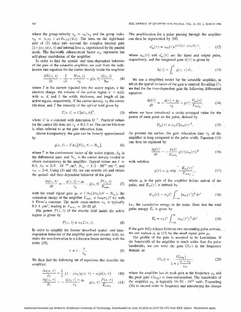
Unidirectional ring configuration for passive mode-locking. Fig. 1.
in which a slow saturable amplifier and absorber are present. In our discussion, we make some suitable approximations in order to find a closed-form analytical solution to the mode- locking problem. The mode-locking system is described in terms of the bandwidth, self-phase modulation and dispersion of the system, the saturation energy of the saturable amplifier and absorber, and the ratio of the gain and absorber relaxation time to the pulse repetition time. The cavity elements that determine these parameters are described in Section II-A-II- D. In Section 111, we derive the mode-locking equation and in Section IV the solution to it. In Section V, the stability of the mode-locking system is analyzed, and the conditions under which steady-state mode-locking solutions are found are derived. In this section, we also graphically show how the energy and width of the generated pulses are influenced by the different system elements. In Section VI, the effects of dispersion and self-phase modulation of the system are discussed. Finally, in Section VII, we show that the theory presented in this paper can also be applied to bidirectional ring cavities and Fabry-PCrot cavities by taking into account the effects of pulse collisions that can occur in these laser structures and the position of the different system elements inside the cavity.
11. MODE-LOCKING CONFIGURATION In this section, we derive the properties of a passively mode-
locked unidirectional ring laser. The theory of passive mode- locking for (dye) lasers has been introduced and extended by Haus [20]-[22], [25]-[28]. The theory presented here follows the lines of a paper by Haus [20]. However, at several points, we have made modifications and extensions. Some of these extensions include the effects of self-phase modulation and pulse collisions on the system.
We consider a unidirectional ring configuration with a semiconductor laser amplifier (L), a saturable absorber (A), a bandwidth limiting element (B) to take into account the bandwidth and cavity loss of the system, and a dispersive element (D) representing the dispersion of the system (see Fig. 1).
Starting with our theoretical analysis, we make the following assumptions and approximations.
1) Both the amplifier and absorber are assumed to be only time-dependent. Any spatial variations of the gain and
absorption coefficient inside the amplifier and absorber, respectively, are neglected. This simplification allows us to obtain analytical solutions to the mode-locking problem. The dispersion of the system is determined by the wavelength and material dispersion introduced by the different system elements, like amplifier, absorber, and cavity. The bandwidth of the system is determined by the amplifier/absorber. If we want to obtain analytical so- lutions to the mode-locking problem, we can not assign this bandwidth limitation to the gaidabsorber medium. Therefore, we have introduced the bandwidth limiting element in Fig. 1, which not only takes into account the bandwidth limitation of the system, but also the cavity loss. The gain relaxation time is considered long compared to the pulse width. This is a valid assumption because, in practice, the gain recovery time is about 0.2-1 ns, while the pulses generated lie normally in the low picosecond range. In semiconductor lasers, the absorber relaxation time is in the order of 10-15 ps [29]; so if we consider generating pulses in the low picosecond range, the saturable absorber acts as a slow absorber.
We assume that a pulse has formed in the semiconductor laser configuration of Fig. 1, so that on the mth pass around the ring, the electric field &(t) can be written as
E,(x, t ) = a,(z, t )e jwot , (1)
where a,(z, t ) is the envelope of the electric field at the mth pass, and WO is the optical carrier frequency of the electric field. We ignore the details of transverse field patterns and treat the electric field as a plane wave. Note that the Fourier transform of the envelope of the electric field a,(z, w ) and of the electric field itself E(z , w ) are related to each other by
& ( z , w ) = a,(z, w - WO). (2)
In the following sections, we first describe the different elements of the cavity, using the aforementioned assumptions and approximations, after which we derive the passive mode- locking equation and the solution to it.
A. Saturable AmpliJier
First of all, we investigate how one single pulse is influenced by a saturable amplifier. Therefore, we consider a traveling- wave amplifier and assume that the active region dimensions of the amplifier are such that the amplifier supports a single lateral waveguide mode. We assume that the electric field inside the amplifier can be represented by (1). The evolution of the slowly varying amplitude a ( z , t ) of the electric field along the amplifier length is then described by
- - da(z , t ) 1 d a ( z , t ) +-- vg at a z (3) 1
3 [(I - j a L ) g ( z , t ) - a,la(z, t ) ,
Authorized licensed use limited to: Eindhoven University of Technology. Downloaded on June 24,2010 at 10:57:05 UTC from IEEE Xplore. Restrictions apply.
480 IEEE JOURNAL OF QUANTUM ELECTRONICS, VOL. 32, NO. 3, MARCH 1996
where the group-velocity vg = cO/ng and the group index ng = n,ff + w ( d n , f f / d w ) . The term on the right-hand side of (3) takes into account the complex internal gain ( 1 - j a L ) g ( z , t ) and internal loss Q, experienced by the guided mode. The linewidth enhancement factor a~ represents the self-phase modulation of the amplifier.
In order to find the spatial- and time-dependent behavior of the gain of the saturable amplifier, we start from the well- known rate-equation for the carrier density inside the amplifier
where I is the current injected into the active region, e the electron charge, the volume of the active region V = w d L with w, d , and L the width, thickness, and length of the active region, respectively, N the carrier density, TL the carrier life-time, and Z the intensity of the optical field given by
(5)
where C is a constant with dimension R-’. Practical values for the carrier life-time are TL = 0.2-1 ns. The carrier life-time is often referred to as the gain relaxation time.
Above transparency, the gain can be linearly approximated
(6)
where I? is the confinement factor of the active region, AL is the differential gain, and N,, is the carrier density needed to obtain transparency in the amplifier. Typical values are I‘ = 0.3, AL = 2-3 . cm2, N,, = 1-2 . l0ls ~ m - ~ , and CUL = 2-6. Using (5) and (6), we can rewrite (4) and obtain the spatial- and time-dependent behavior of the gain
qz, t ) = Cla(z, t)I2,
by
g ( z , t ) = YAL[N(Z, t ) - &,I,
The amplification for a pulse passing through the amplifier can then be represented by [18]
a’ m (.) 1 a m ( r ) e ( l / 2 ) ( l - ~ ~ ~ ) ~ ( T ) , (12)
where a,(r) and a;(.) are the input and output pulse, respectively, and the integrated gain h(r) is given by
h(r) = iL g ( z , r ) d z . (13)
We use a simplified model for the saturable amplifier, in which the spatial variation of the gain is omitted. Recalling (7), we find for the time-dependent gain the following differential equation:
where we have introduced a cavity-averaged value for the power of each point on the pulse, defined by
As pointed out earlier, the gain relaxation time r~ of the amplifier is long compared to the pulse width. Equation (14) can then be replaced by
with solution
where 9% is the gain of the amplifier before arrival of the pulse, and Em(r) is defined by
Em(r) = OLC lum(r’)12 dr’ (18) with the small signal gain 90 = I’AL(IrL/eV - N,,), the
i i Dirac’s constant. The mode cross-section a~ is typically 0.3-1 bm2, leading to EsatL = 10-20 pJ.
The power P ( z , t ) of the electric field inside the active
saturation energy of the amplifier EsatL = fiWOoL/I‘AL with 1:
Et = CJLC 1, lum(r’)l2 dr’.
i.e., the cumulative energy in the pulse. Note that the total pulse energy Et is given by
region is given by 00
(19) P ( z , t ) = aLZ(z, t ) . (8)
In order to simplify the former described spatial- and time- dependent behavior of the amplifier gain and electric field, we make the transformation to a reference frame moving with the pulse [30]
If the gain fully relaxes between two succeeding pulse arrivals, we can rep1ace 9% in (17) by the
If the bandwidth of the amplifier is much wider than the pulse bandwidth, we can write the gain G ( w ) in the frequency
gain 90. The profile Of the gain is assumed to be
z 21”
r = t - - . (9) domain as
We then find the following set of equations that describe the amplifier:
da(z, r ) = - I [(I - j a L ) g ( z , .) - a,]a(z, .) where the amplifier has its peak gain at the frequency wp and d z 2 the-peak gain G ( w p ) is time-independent. The bandwidth of
d g k , 7 ) - 9(z, 7) -90 ‘(‘1 (11) the amplifier WL is typically 10-50 . 1OI2 rads. Expanding d r 7-L Esa tL (20) to second order in frequency and introducing the change
(10)
- g(z , 7 ) ~
~- -
Authorized licensed use limited to: Eindhoven University of Technology. Downloaded on June 24,2010 at 10:57:05 UTC from IEEE Xplore. Restrictions apply.
KOUMANS AND VAN ROIJEN: THEORY FOR PASSIVE MODE-LOCKING IN SEMICONDUCTOR LASER STRUCTURES
in the carrier frequency from the frequency at peak gain as A w = W O - wp, we have
G ( w ) = G ( w , ) (I- ( $ ) 2 - j z - A w (1--2j$)
(i 5) + ( j yy]. Using (2) and Fourier analysis, we can make the following transformations from the frequency domain to the time domain for the field envelope:
1 d2 w i d r 2 (i y)2 am(w) - - - um(r) . (22)
Taking the length of the amplifier l ~ , we find for the transfer of the field envelope through the amplifier
a m (TI, (23) a’ (.) == & / W - h ) b ( 4 m
where the transfer function hL ( r ) of the amplifier is defined by
. A w
A w 1 d 1 d2 - (1-2j--)-- W L d r + - W: -1. d r 2 (24)
Examining (24), we recognize the bandwidth limitation of the amplifier and see that the action of the amplifier upon the pulse causes a shift in time ( d l d r ) and a diffusion in time ( d 2 / d r 2 ) .
In order to obtain analytical solutions to the mode-locking problem, we can not assign the bandwidth limitation to the gain element. Therefore, we have to introduce a bandwidth limiting element in the mode-locking configuration (see Fig. 1) that is described in Section 11-C. Omitting now the bandwidth limitation and using (17), we find for the transfer of the field envelope through the amplifier (23), now with h ~ ( 7 ) of the amplifier defined by
where g ( r ) is defined according to (17). Next, we investigate what happens if succeeding pulses
enter the saturable absorber. Therefore, we derive a relation between time-dependent gain g(r) and the small signal gain go. We assume that the gain at the arrival of a pulse equals gz and at the end of a pulse g f . Between two pulse arrivals, the gain can only relax up to g$ 5 go. Then the next pulse comes along and saturates the gain to gf = gz exp ( -Et /EsatL) . After the pulse passage, the gain relaxes back to go according to
~
481
Eliminating gf and solving (26) for go gives at amval of the next pulse at T = Tp”
Note that the time between two pulse arrivals T; for the unidirectional ring cavity displayed in Fig. 1 equals the cavity round-trip time TR .
B. Saturable Absorber
We can do the same calculations for the saturable absorber, as for the saturable amplifier. In analogy, we then find for the absorption
q(r) = qi exp [-%I with Esata = hwOnA/I’AA where CA is the absorber mode cross-section and where AA is the differential absorption. The absorption of the absorber before arrival of the pulse equals 4;. If the absorber fully relaxes between the pulse arrivals, we can replace q; by 40, defined by
where NtA is the carrier density needed to obtain transparency in the absorber, and TA is the absorber relaxation time. Taking the length of the amplifier Z A , we find for the evolution of the field envelope passing through the absorber
a’ m (.) = e ( l / 2 ) ( 1 - - j a ~ ) h ~ ( ~ ) am ( r ) > (30)
where Q A the linewidth enhancement factor of the absorber and where the transfer function h ~ ( r ) of the absorber is defined by
where we have taken the bandwidth limitation of the absorber equal to the one of the amplifier. The bandwidth limitation has to be dropped again in order to find analytical solutions to the mode-locking problem. Using (28), we now find for the transfer of the field envelope (30), with the transfer function /LA(‘) of the absorber defined by
d r ) = go - with q(r) defined according to (28). Typical values for the saturable absorber are TA = 10-15 ps, AA = 10-20 .
Authorized licensed use limited to: Eindhoven University of Technology. Downloaded on June 24,2010 at 10:57:05 UTC from IEEE Xplore. Restrictions apply.

482 IEEE JOURNAL OF QUANTUM ELECTRONICS, VOL. 32, NO. 3, MARCH 1996
cm2, OA = 0.3-1 pm2, NtA = 0.5-1 lo1’ cm4, Esata = 1-10 pJ, and O ~ A =2-6.
In the same way as we did for the saturable amplifier, we
can derive the following relation between the small-signal D = ~ L ( $ ) ~ + ~ A ( $ ) ~ + ~ c ( $ ) (38) absorption qo and the absorption before arrival of the pulse Y 2 :
with 1 ~ . Z A , and Zc the length of the amplifier, absorber, and cavity, respectively. Note that we have omitted a term with linear dependence on frequency in the phase function ( ~ ( w ) ,
system, given by
where cpo is a constant phase shift, and D is a measure for the velocity dispersion in the system, defined by
C 1) (33) because this term represents the round-trip delay TR in the
where T: is the time between two succeeding pulse arrivals in the saturable absorber. Note that this time does not need C
to equal the time between two pulse arrivals in the saturable amplifier but depends on the position of the amplifier and absorber in the cavity and the number of pulses inside the cavity.
C. Bandwidth Limiting Element
To include the bandwidth limitation of the gain and ab- sorber, we have introduced a bandwidth-limiting element in the mode-locking system. In this bandwidth-limiting element, the loss of the cavity is also included. As we have seen in (24), the bandwidth limitation of the amplifier causes a shift in time and a diffusion in time of the field envelope of the electric field. The transfer function of the bandwidth limiting element can be represented by
A w W L
where QC is the cavity loss of the system and IC the cavity length and where we have used
G ( w ) ~ L = Q(w)ZA + aclc. (35)
The pulse repetition time is thus determined by the time needed to travel through the cavity.
Making the transformation back to the time domain for cp(w), we find for the transfer of the field envelope through the dispersive element
where the transfer function h D ( 7 ) is defined by
111. MODE-LOCKING EQUATION Knowing the influences of the cavity elements on the field
envelope u,(T), we are able to derive the mode-locking equation for the system. For the pulse envelope am+l ( T ) after one cavity round-trip we find
We assume that a pulse propagating through any of the elements of the mode-locking system, amplifier, saturable absorber, etc., is modified only slightly (say 20% gain or loss) on one round-trip. This assumption enables us to expand the exponential in (42) to first order in its argument, leading to
The change of the field envelope by the bandwidth-limiting element is given by
a’ m ( r ) = e(1/2)hB(T) am > (36) am+l(T)
1 - $ (1 - j a A ) q ( r ) Z A + f (1 - j a L ) g ( r ) Z L
- -crczc 1
.
[’+ (%)2 + j g + (1 - 2 j 2) 2
1 d 1 d 2 W L d r w i d r 2
i where the transfer function ~ B ( T ) is defined by (34).
D. Dispersive Element
In order to take into account the phase changes of the field envelope and dispersion of the system, we introduce a dispersive element. As mentioned before, we assume that the dispersion of the system is determined by the wavelength and material dispersion introduced by the different system
in the frequency domain can be represented by
- j ( p ~ - i , ~ ) ) a , ( r ) . d r 2
elements. The phase function ( ~ ( w ) of the dispersive element (43)
Now U ~ + ~ ( T ) does not need to be equal to a,(r) because some of the pulse shaping may lead to delays or advances of d w ) = (Do + q w - (37)
Authorized licensed use limited to: Eindhoven University of Technology. Downloaded on June 24,2010 at 10:57:05 UTC from IEEE Xplore. Restrictions apply.
KOUMANS AND VAN ROUEN: THEORY FOR PASSIVE MODE-LOCKING IN SEMICONDUCTOR LASER STRUCTURES 483
the pulse. For the round-trip condition, we then find
am+l(r) = am(r + AT), (44)
where AT represents the time shift of the pulse. By this definition, a positive value of AT represents a shift backward in time. If we now expand u,(r + AT) to first order in AT, we find
(45)
Substituting (17), (28) and (45) into (43) and omitting the subscript m, we find the passive mode-locking equation
1 + (1 - j a ~ ) & i exp
- (1 - j a ~ ) G i exp
1 d + E 2 + j (E + $1 + (1 + 8 - 2 jE)
where we have introduced normalized amplifier and absorber parameters
Qk with ,k = 0, i, f aclc
G k with k = 0, i , f , (47) aclc and normalized system parameters
Typical values are ac = 1-2 cm-', I C = 0.1-1 cm, W L = 10-50 10l2 rads, and D = 1-10 . s2, leading to V = 5-25. Note that
is the net gain parameter. This parameter plays a very impor- tant role in the mode-locking problem.
Iv. SOLUTION TO THE MODE-LOCKING EQUATION Equation (46) is a nonlinear differential equation that looks
quite complicated. A simple solution of (46) is obtained if we expand the exponentials to second order in their argument.
Because EsatL > E,,t,, as will become clear later on, we may break off the expansion of exp[E(r) /ESatL] with the first-order term, so that we obtain
1 + (1 - j a A ) Q , - (1 - j Q L ) 6 t
where we have introduced the stability parameter
(5 1) EsatL Esata
s 1 PI
The differential equation (50) can be solved analytically by introducing a guess [22] for the pulse envelope a(.)
1+JP
a(.) = a0 [sech( 31 , (52)
where the amplitude a0 = JV,Esat,/20Cr0 with V, = Et/ESatA. The pulse shape denoted by (52) is a hyperbolic secant. As a result of (52), we have
E ( T ) = ~ [1+ tanh (31 7 0 - a(.) = -(I + j p ) tanh (L) U(.)
(53)
(54)
2 d
d r 70
-(2 + 3 j P - p2) sech2
Substituting the above equations into (50) and equating the coefficients of the terms u ( r ) , U(.) tanh(r/rO), and U(.) sech2 ( r / T o ) , yields three complex algebraic equations. The real and imaginary parts of these three complex equations are
Authorized licensed use limited to: Eindhoven University of Technology. Downloaded on June 24,2010 at 10:57:05 UTC from IEEE Xplore. Restrictions apply.
484 IEEE JOURNAL OF QUANTUM ELECTRONICS, VOL. 32, NO. 3, MARCH 1996
1+Q,-8;+E2-- Q i - - V,+-QiY2 1 2 I ( 7) 4
These six equations have six unknowns: TO, V,, ,B, 6, [, and $. In principle, the system can be solved consistently for different Qi and Gi.
V. MODE-LOCKING CONDITIONS
In this section, we derive the boundaries for stable pulse mode-locking solutions. These boundaries are graphically shown in the GO-!& plane. We start with describing the conditions for stable mode-locking.
The net gain as a function of the normalized energy U ( T ) = Et(r) /Esat , has the dependence
8 T [ U ( T ) ] =-(I + Qz - 8,)
In order to avoid that perturbations preceding the pulse can grow, the net gain preceding the pulse (U(.) = 0) must be negative, leading to
Note that in order to start the mode-locking system, we must have
40 > 1 + Qo. (64)
It is important to note that if the amplifier relaxes fully between two incoming pulses, i.e. 4, = 60, we can not fulfill (63). As Q, 5 QO and 8, = GO, we have 6, > 1 + Qz, which is not in agreement with (63). So (63) together with (64) leads to the mode-locking condition T L / T ~ 2 1, i.e., the amplifier should not recover completely between two succeeding pulse arrivals. In order to avoid that perturbations following the pulse can grow, we must satisfy the stability criterion that the net gain is negative after passage of the pulse ( U ( 7 ) = V,), leading
threshold - _ - ' ,, I.
1 2 3 4 5 Q o -+
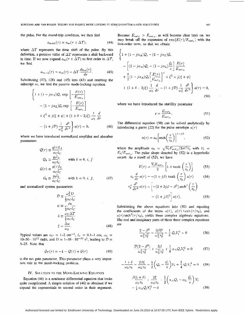
Fig 2. Stabihty boundaq (grey area between dashed lines), laser threshold (dash-dotted line), and equipulse energy lines (solid lines) as a function of normahzed small signal gain and absorption for rL/Tp = 5, rA/Tp = 0.1, s = 6 , V = 0, CYA = 0, and LYL = 0
(0 = 0), that no phase shift is present on one round-trip ($I = 0). and that the carrier frequency coincides with the peak gain frequency ( E = 0).
In Fig. 2, we have drawn the stability boundaries as a function of the normalized small signal gain 80 and normalized small signal absorption QO.
The area in which stable mode-locking is possible is given by the grey area between the two dashed lines. The laser threshold 80 = 1 + QO is given by the dash-dotted line. We have also plotted the normalized pulse energy V, in the Go-Qo plane. The solid lines are equipulse energy lines, i.e., they connect points in the Go-Qo plane that produce mode-locked pulses with the same energy.
As we can see in Fig. 2, the energy of the pulse increases if the gain is raised. For each value of the normalized small signal absorption Qo, there is a minimum pulse energy required to obtain steady state mode-locking. This is understandable because pulses with low energy can only pull down the gain by small amounts. However, the gain must be pulled down below the loss at the wings of the pulse. Otherwise, the pulse is unstable to noise perturbations preceding and following the pulse. Consequently, stable pulse operation requires a minimum pulse energy, which can be derived from 8, = I+ Q, and from
to 1
-(I + Q, - 4,) + V, - Qzv," < 0. (65) Go = 4,
A last condition for the pulse is that the loss must be converted into gain with rising pulse energy, which means that the coefficient of ( Qz - Gz/s) in (62) must be positive, leading to
(66) 8, < s a .
First, we consider the mode-locking system when dispersion and self-phase modulation are absent.
If dispersion and self-phase modulation are absent ( D = 0, a~ = 0, and QA = 0), we find that the pulse is not chirped
These equations lead to a minimum pulse energy
= - ln { exp (z) - A [exp (z) - I]}, E s a t ~
(68)
Authorized licensed use limited to: Eindhoven University of Technology. Downloaded on June 24,2010 at 10:57:05 UTC from IEEE Xplore. Restrictions apply.

KOUMANS AND VAN ROUEN THEORY FOR PASSIVE MODE-LOCKING IN SEMICONDUCTOR LASER STRUCTURES 485
I 1 2 3 4 5 1; ”
Qo + Fig. 3. Stability boundary (grey area between dashed lines), laser threshold (dash-dotted line) and equipulse width lines (solid lines) as a function of normalized small signal gain and absorption for T L / T ~ = 5, r*/TP = 0.1, s = 6, V = 0, = 0, and a~ = 0.
where &; is given by
r 1
Of course there is also a maximum value of the pulse energy if we want to obtain stable mode-locking. If the energy is raised above this value, then there is a positive net gain & for perturbations preceding the pulse. This means that the system will eventually work under continuous wave (the net gain 6~ is always positive).
Furthermore, we can draw a very important conclusion from the analysis. The stability regime has an intersection point with the threshold line. This intersection point is given by Qo = l / ( s - 1) and 60 = s / ( s - 1). We see that for values of s > 1, this point moves toward the origin. For values of s approaching 1, the intersection point moves toward infinity. Values of s < 1 are not allowed because these do not fulfill (66). If we thus want to obtain a stability area that is not to far from the origin, we have to make sure that s > 1. Physically, this means that the amplifier must be harder to saturate than the absorber. Another important advantage of a larger value for s is that the stable mode-locking area becomes larger and that the area moves toward the threshold line. So in order to have a mode-locking system that has a wide range of stable operation and a low threshold, we need a value of s as large as possible. In Fig. 3, we have drawn, in the same way as we did in Fig. 2, equipulse width lines in the Go-Qo plane.
The pulse width ro is mainly determined by the bandwidth of the system. From the normalized pulse width ~ / W L T O , we find that possible pulse widths in the order of 50-100 fs can be obtained.
Finally, we note that we have to check if the system is self- starting and stable against self-pulsations. For this analysis, we refer to a paper by Haus [26].
t G O
1 2 3 4 5 1; ”
QO -b
Fig. 4. Stability boundary (grey area between dashed lines), laser threshold (dash-dotted line) and equipulse energy lines (solid lines) as a function of normalized small signal gain and absorption for T L / T ~ = 5 , r*/Tp = 0.1, s = 6 , V = 10, a* = 0, and CUL = 0.
---- boundary threshold 1
‘0 1 2 3 4 5 Q o +
Fig. 5. Stability boundary (grey area between dashed lines), laser threshold (dash-dotted line) and equipulse width lines (solid lines) as a function of normalized small signal gain and absorption for T L / T ~ = 5, r*/TP = 0.1, s = 6 , 2, = 10, CY* = 0, and a~ = 0.
VI. EFFECTS OF DISPERSION AND SELF-PHASE MODULATION
A. Dispersion
We now investigate the influence of dispersion on the mode- locking system. If dispersion is not neglected (’23 # 0), we find that the pulse is chirped (p # 0) and that a phase shift is present on one round-trip ($ # 0). The carrier frequency of the electric field does also not coincide with the frequency at peak gain (5 # 0). In Figs. 4 and 5, we give the equipulse energy lines and equipulse width lines in the Go-Qo plane for s = 6, 2) = 10, TL/T, = 5 and rA/T, = 0.1.
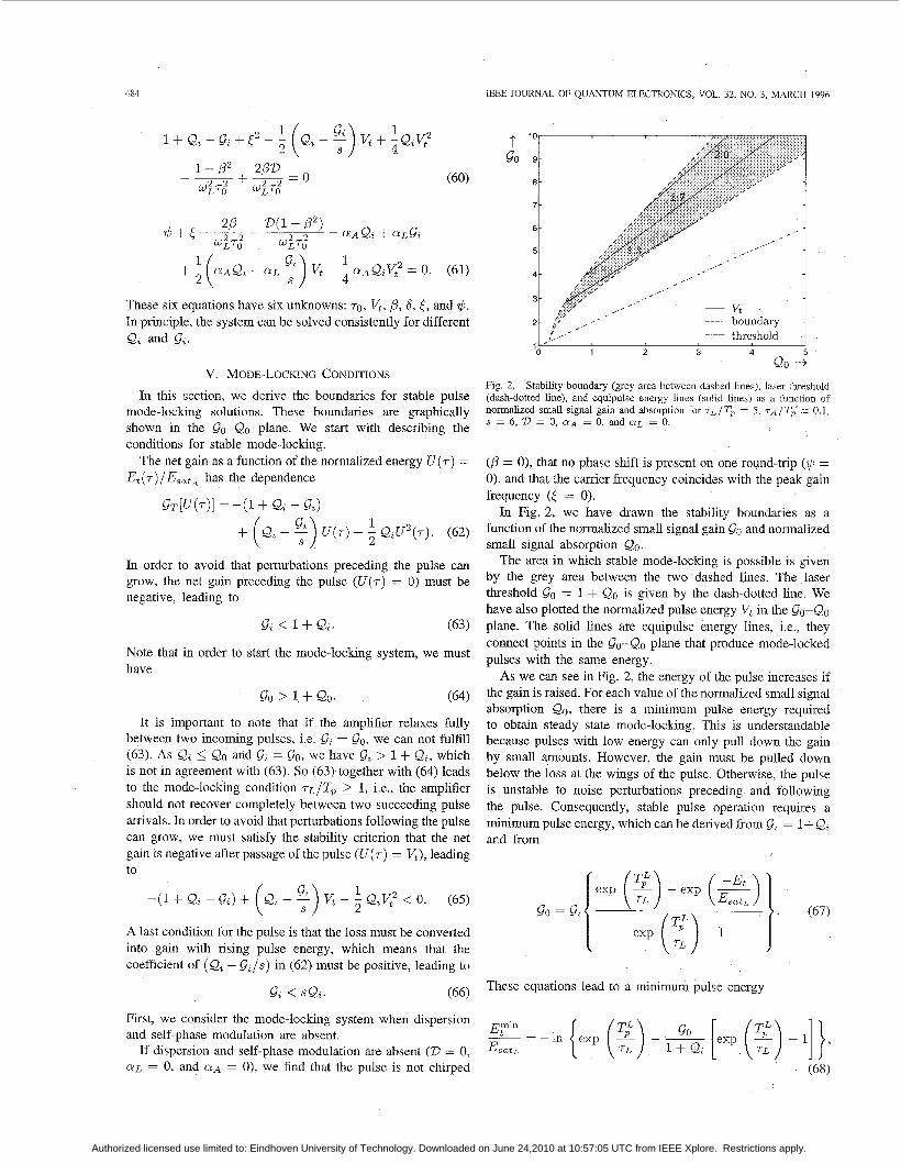
In order to find out more exactly what the effect of disper- sion on the different system parameters is, we have drawn the normalized pulse energy, pulse width, and chirp parameter as a function of dispersion in Fig. 6.
As we can see in Fig. 6, the pulse is broadened if dispersion is present in the mode-locking system. Dispersion not only
Authorized licensed use limited to: Eindhoven University of Technology. Downloaded on June 24,2010 at 10:57:05 UTC from IEEE Xplore. Restrictions apply.
486 IEEE JOURNAL OF QUANTUM ELECTRONICS, VOL 32, NO 3, MARCH 1996
I " -2'0 -10 0 10 20
D-+ 1 t i '
D - 3
t IC '
-20 -10 0 10 20 D - 3
Fig. 6. Normalized pulse energy Vt, pulse width l /wLrO and chirp param- eter /3 as a function of dispersion for QZ = 2, 9, = 2.8, s = 6 , T L / T ~ = 5, T A / T ~ = 0.1, CUA = 0, and CYL = 0.
causes the pulse width to increase but simultaneously poses a chirp on the pulse. Since we have assumed that self-phase modulation in the amplifier and absorber are absent (QL = 0 and QA = O), the chirp caused by dispersion can neither be compensated by the amplifier nor by the absorber. The pulse width is minimum and unchirped only if dispersion is absent. As can be seen from Fig. 6, a normalized dispersion 2) = 10 reduces the achievable pulse width with a factor of about 4. Typical values for pulse widths that can be achieved are 200-500 fs.
B. Self-phase Modulation We now introduce self-phase modulation in the system,
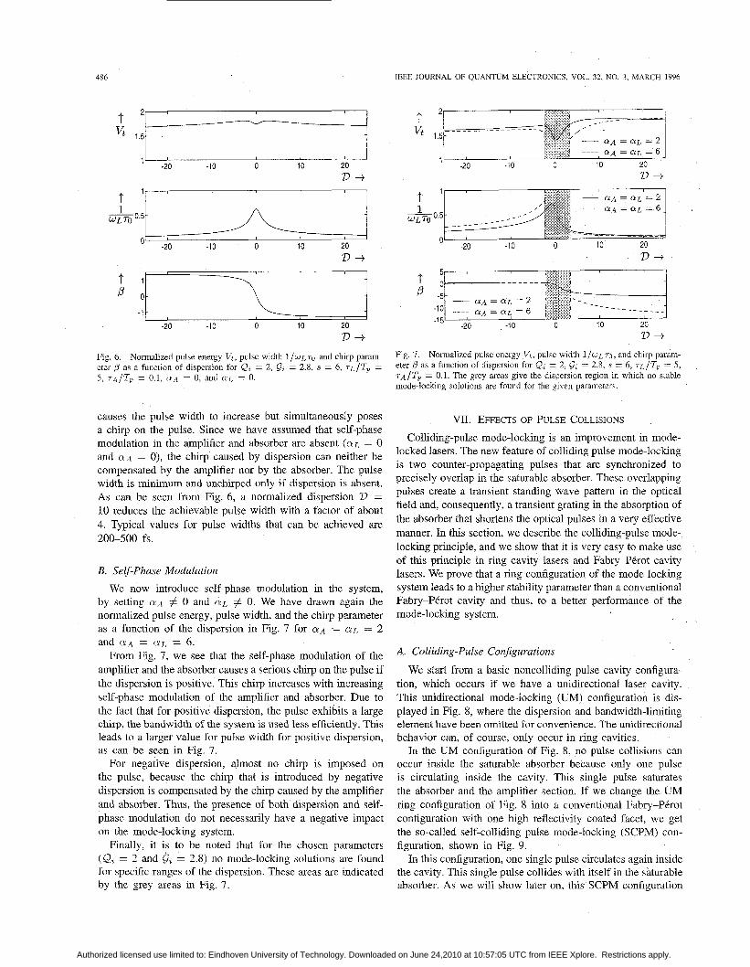
by setting QA # 0 and Q L # 0. We have drawn again the normalized pulse energy, pulse width, and the chirp parameter as a function of the dispersion in Fig. 7 for QIA = Q L = 2 and OIA = Q L = 6.
From Fig. 7, we see that the self-phase modulation of the amplifier and the absorber causes a serious chirp on the pulse if the dispersion is positive. This chirp increases with increasing self-phase modulation of the amplifier and absorber. Due to the fact that for positive dispersion, the pulse exhibits a large chirp, the bandwidth of the system is used less efficiently. This leads to a larger value for pulse width for positive dispersion, as can be seen in Fig. 7.
For negative dispersion, almost no chirp is imposed on the pulse, because the chirp that is introduced by negative dispersion is compensated by the chirp caused by the amplifier and absorber. Thus, the presence of both dispersion and self- phase modulation do not necessarily have a negative impact on the mode-locking system.
Finally, it is to be noted that for the chosen parameters (Q = 2 and G, = 2.8) no mode-locking solutions are found for specific ranges of the dispersion. These areas are indicated by the grey areas in Fig. 7.
1 t 1
0.5
0
D+
D+ Fig. 7. Normalized pulse energy Vt, pulse width ~ / W L T O , and chirp param- eter 3 as a funcuon of dispersion for Q, = 2, 6, = 2.8, s = 6 , T L / T ~ = 5, Q / T ~ = 0.1. The grey areas give the dispersion region in which no stable mode-lockmg solutions are found for the given parameters
VH. EFFECTS OF PULSE COLLISIONS Colliding-pulse mode-locking is an improvement in mode-
locked lasers. The new feature of colliding pulse mode-locking is two counter-propagating pulses that are synchronized to precisely overlap in the saturable absorber. These overlapping pulses create a transient standing wave pattern in the optical field and, consequently, a transient grating in the absorption of the absorber that shortens the optical pulses in a very effective manner. In this section, we describe the colliding-pulse mode- locking principle, and we show that it is very easy to make use of this principle in ring cavity lasers and Fabry-P6rot cavity lasers. We prove that a ring configuration of the mode-locking system leads to a higher stability parameter than a conventional Fabry-Pkrot cavity and thus, to a better performance of the mode-locking system.
A. Colliding-Pulse Configurations
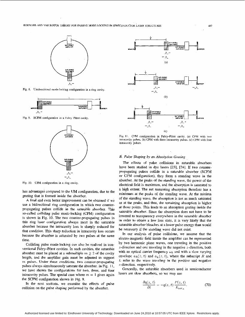
We start from a basic noncolliding pulse cavity configura- tion, which occurs if we have a unidirectional laser cavity. This unidirectional mode-locking (UM) configuration is dis- played in Fig. 8, where the dispersion and bandwidth-limiting element have been omitted for convenience. The unidirectional behavior can, of course, only occur in ring cavities.
In the UM configuration of Fig. 8, no pulse collisions can occur inside the saturable absorber because only one pulse is circulating inside the cavity. This single pulse saturates the absorber and the amplifier section. If we change the UM ring configuration of Fig. 8 into a conventional Fabry-PCrot configuration with one high reflectivity coated facet, we get the so-called self-colliding pulse mode-locking (SCPM) con- figuration, shown in Fig. 9.
In this configuration, one single pulse circulates again inside the cavity. This single pulse collides with itself in the saturable absorber. As we will show later on, this SCPM configuration
Authorized licensed use limited to: Eindhoven University of Technology. Downloaded on June 24,2010 at 10:57:05 UTC from IEEE Xplore. Restrictions apply.
KOUMANS AND VAN ROIJEN: THEORY FOR PASSIVE MODE-LOCKING IN SEMICONDUCTOR LASER STRUCTURES 487
A- Fig. S. Unidirectional mode-locking configuration in a ring cavity.
MIRROR MIRROR
A- Fig. 9. SCPM configuration in a Fabry-PCrot cavity.
A- -JL
Fig. 10. CPM configuration in a ring cavity.
has advantages compared to the UM configuration, due to the grating that is formed inside the absorber.
A final and even better improvement can be obtained if we use a bidirectional ring configuration in which two counter- propagating pulses collide in the saturable absorber. This so-called colliding pulse mode-locking (CPM) configuration is shown in Fig. 10. The two counter-propagating pulses in this ring laser configuration always meet in the saturable absorber because the intracavity loss is sharply reduced for that condition. This sharp reduction in intracavity loss occurs because the absorber is saturated by two pulses at the same time.
Colliding pulse mode-locking can also be realized in con- ventional Fabry-PCrot cavities. In such cavities, the saturable absorber must be placed at a submultiple m 2 2 of the cavity length, and the amplifier gain must be adjusted to support m pulses. Under these conditions, two counter-propagating pulses always simultaneously saturate the absorber. In Fig. 11, we have shown the configurations for two, three, and four intracavity pulses. The special case where m = 1 gives again the SCPM configuration shown in Fig. 9.
In the next sections, we examine the effects of pulse collision on the pulse shaping performed by the absorber.
L - c I
MIRROR MIRROR
A- -A
(a)
MIRROR MIRROR
A- -A -A.
(b)
L - C ' 4
MIRROR MIRROR
A- A- -A -A
(c)
Fig. 11. CPM configuration in Fabry-PCrot cavity. (a) CPM with two intracavity pulses. (b) CPM with three intracavity pulses. (c) CPM with four intracavity pulses.
B. Pulse Shaping by an Absorption Grating
The effects of pulse collisions in saturable absorbers have been studied in dye lasers [23] , [24]. If two counter- propagating pulses collide in a saturable absorber (SCPM or CPM configuration), they form a standing wave in the absorber. At the peaks of the standing wave, the power of the electrical field is maximum, and the absorption is saturated to a high extent. The net remaining absorption therefore has a minimum at the peaks of the standing wave. At the minima of the standing wave, the absorption is not as much saturated as at the peaks, and thus, the remaining absorption is higher at those points. This leads to an absorption grating inside the saturable absorber. Since the absorption does not have to be lowered to transparency everywhere in the saturable absorber in order to obtain a low loss state, it is very likely that the saturable absorber bleaches at a lower pulse energy than would be necessary if the standing wave did not exist.
In our analysis of pulse collisions, we assume that the electro-magnetic field inside the amplifier can be represented by two harmonic plane waves, one traveling in the positive x-direction and one traveling in the negative x-direction, both with an optical carrier frequency WO and with a slow varying envelope U R ( Z , t ) and UL(Z, t ) , where the subscript R and L refer to the wave traveling in the positive and negative z-direction, respectively.
Generally, the saturable absorbers used in semiconductor lasers are slow absorbers, so we may use
Authorized licensed use limited to: Eindhoven University of Technology. Downloaded on June 24,2010 at 10:57:05 UTC from IEEE Xplore. Restrictions apply.
488 IEEE JOURNAL OF QUANTUM ELECTRONICS, VOL 32, NO 3, MARCH 1996
We now spatially expand the absorption q(z , t ) in Fourier elements to second order
By substituting (7 1) into (70) and neglecting fourth-order terms, we find the following equations:
The change of the electric field within the absorber is described by Maxwell’s equations. Using the rotating wave approximation [23], we find for the amplitudes of the harmonic waves traveling in the positive and negative z-direction
The amplitude of the pulse is diminished by absorption and by scattering into the opposite direction and is supplemented by scattering from the counter-propagating pulse.
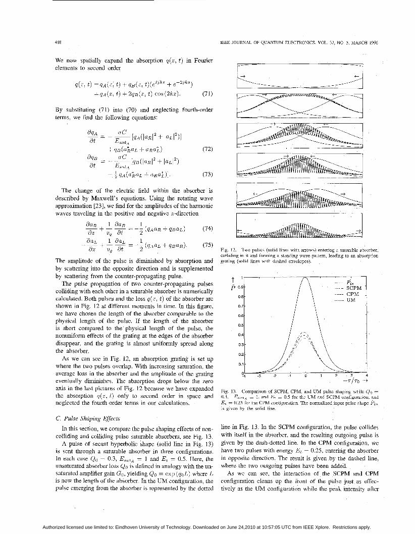
The pulse propagation of two counter-propagating pulses colliding with each other in a saturable absorber is numerically calculated. Both pulses and the loss q ( z , t ) of the absorber are shown in Fig. 12 at different moments in time. In this figure, we have chosen the length of the absorber comparable to the physical length of the pulse. If the length of the absorber is short compared to the physical length of the pulse, the nonuniform effects of the grating at the edges of the absorber disappear, and the grating is almost uniformly spread along the absorber.
As we can see in Fig. 12, an absorption grating is set up where the two pulses overlap. With increasing saturation, the average loss in the absorber and the amplitude of the grating eventually diminishes. The absorption drops below the zero axis in the last pictures of Fig. 12 because we have expanded the absorption q ( z , t ) only to second order in space and neglected the fourth-order terms in our calculations.
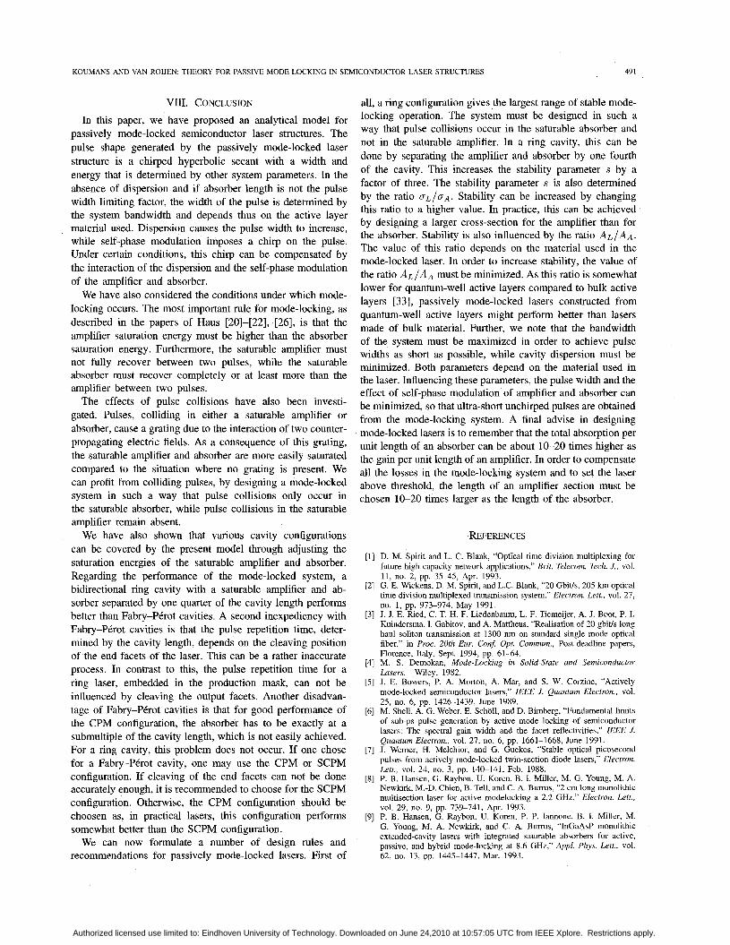
C. Pulse Shaping Ejfects In this section, we compare the pulse shaping effects of non-
colliding and colliding pulse saturable absorbers, see Fig. 13. A pulse of secant hyperbolic shape (solid line in Fig. 13)
is sent through a saturable absorber in three configurations. In each case Qo = 0.3, E,,,, = 1 and Et = 0.5. Here, the unsaturated absorber loss QO is defined in analogy with the un- saturated amplifier gain Go, yielding QO = exp (q&) where L is now the length of the absorber. In the UM configuration, the pulse emerging from the absorber is represented by the dotted
I - I
Fig. 12. Two pulses (solid lines with arrows) entering a saturable absorber, colliding in it and forming a standing wave pattem, leading to an absorption grating (solid lines with dashed envelopes).
Fig. 13 Companson of SCPM, CPM, and UM pulse shaping while QO = 0 3, E,,&, = 1, and Et = 0 5 for the UM and SCPM configuration and Et = 0 25 for the CPM configuration The normalized input pulse shape P%, is given by the solid line
line in Fig. 13. In the SCPM configuration, the pulse collides with itself in the absorber, and the resulting outgoing pulse is given by the dash-dotted line. In the CPM configuration, we have two pulses with energy Et = 0.25, entering the absorber in opposite direction. The result is given by the dashed line, where the two outgoing pulses have been added.
As we can see, the interaction of the SCkM and CPM configuration cleans up the front of the pulse just as effec- tively as the UM configuration while the peak intensity after
Authorized licensed use limited to: Eindhoven University of Technology. Downloaded on June 24,2010 at 10:57:05 UTC from IEEE Xplore. Restrictions apply.

KOUMANS AND VAN ROUEN: THEORY FOR PASSIVE MODE-LOCKING IN SEMICONDUCTOR LASER STRUCTURES 489
- SCPM E,,t,=l f ’ p 09- ---- UM ~ , , ~ , = o . s i
0.8 - UM E,,t,=l -
0 7-
0 6 -
05-
0 4 -
03- ::U, , ,< 1 04 -3 -2 -1 0 1 2 3 4
-7-/To + Fig. 14. Similar pulse shaping for the UM and SCPM configuration by changing the saturation energy of the absorber while Et = 0.5 for the UM and the SCPM configuration.
p 0.9 ‘ I 0.8
0.6 0.71
0.51 I __L
0
Fig. 15. Similar pulse shaping for the UM and CPM configuration by changing the saturation energy of the absorber while Et = 0.5 for the UM and Et = 0.25 for the CPM configuration.
transmission is higher for colliding pulses with the SCPM configuration having the highest intensity. For the precise influence of the grating in the SCPM and CPM configuration compared to the same configurations without the grating ( q ~ = 0 in (71)-(75)), we refer to papers by Helkey and Derickson [29], [31] and a to paper by Jones et al.
Further examining Fig. 13, we see that the pulse shaping by colliding pulses still exhibits a basic saturation characteristic (pulse compression and timing shift). We may expect that similar pulse shaping can be obtained for a single pulse by adjusting the saturation energy of the absorber. We have done this in Fig. 14 for the SCPM configuration and in Fig. 15 for the CPM configuration.
In both figures, the solid lines represent the normalized transmitted shape of each pulse for the SCPM and CPM configuration, respectively. The dotted lines represent the transmitted shape for the UM configuration, while the (dashed) lines, representing the transmitted shape for the UM configu- ration with an adjusted absorber saturation energy, completely coincide with the solid lines. This means that the pulse shaping
TABLE I CHANGES IN THE SYSTEM PARAMETERS FOR
DIFFERENT MODE-LOCKING CONFIGURATIONS
Configuration T,” T,” EsatL Esatn s Fig. 8 1.0 1.0 1.00 1.00 1.0 Fig. 16(a) 1.0 1.0 0.69 0.67 1 .0 Fig. 16(b) 0.5 1.0 2.00 0.67 3.0 Fig. 16(c) 0.5 1.0 1.00 0.51 2.0 Fig. 16(d) 0.5 0.5 1.18 0.67 1.8
by the SCPM and CPM is almost identical to the pulse shaping by a UM absorber with a saturation energy that is 51 and 67%, respectively, of the saturation energy of the SCPM and CPM absorber. In other words, identical absorbers give higher pulse powers in colliding pulse configurations than in the UM configuration.
We can, of course, perform the same analysis for pulses that collide in the saturable amplifier. We then find that the pulse shaping by the SCPM and CPM amplifier is almost exactly the same as the pulse shaping by a UM amplifier with a saturation energy that is 59 and 69%, respectively, of the saturation energy of the SCPM and CPM amplifier, respectively. The effective gain of an amplifier with a low saturation energy is less than the gain of one with a higher saturation energy. In other words, identical amplifiers give higher pulse powers if pulse collisions in the amplifier are avoided.
D. Enhanced Mode-Locking Stability
In this section, we compare the stability of a number of configurations for colliding pulse mode-locking. In Fig. 16(a), we have displayed the simplest CPM configuration in a ring cavity. As we have discussed in the preceding section, we only want to have pulse collisions in the saturable absorber and not in the saturable amplifier. For the ring-cavity, this means that the amplifier must not be opposite to the absorber (as displayed in Fig. 16(a)).
By separation of the absorber and amplifier by one quarter of the cavity, the pulses never collide inside the amplifier while the interval between the pulse arrival time is made large and equal for both pulses. In Fig. 16(b), we have shown this configuration.
For Fabry-PCrot cavities, we examine the SCPM configura- tion where the absorber is at one mirror while the amplifier is in the middle of the cavity in order to avoid pulse collisions inside the amplifier (see Fig. 16(c)). The CPM configuration can be established by putting the absorber in the middle of the cavity and the laser at one mirror end (in order to reach maximum pulse arrival time). For this configuration, however, we can not avoid that the pulses collide with themselves inside the amplifier. This configuration is displayed in Fig. 16(d).
In Table I, we have shown the changes in saturation energies and pulse arrival times for the absorber ( T t ) and amplifier (Tk). All values are normalized to the values of the UM configuration of Fig. 8. Also the resulting change in the stability parameter s is calculated.
Evaluating Table I, we see that the configuration of Fig. 16(a) behaves almost exactly as the UM configuration
Authorized licensed use limited to: Eindhoven University of Technology. Downloaded on June 24,2010 at 10:57:05 UTC from IEEE Xplore. Restrictions apply.

490 E E E JOURNAL OF QUANTUM ELECTRONICS, VOL. 32, NO. 3, MARCH 1996
Fig. 17. Stability boundary (area between drawn lines of the same kind) as a function of normahzed small signal gain and absorption, for different mode-locking configurabons, while rA/TR = 0 1, rL/TR = 5, 'D = 10, CYA = 0, and CUL = 0. For the other system parameters, see Table I.
MIRROR MIRROR
L 2 -
t
MIRROR MIRROR
A- -A
(d)
Fig 16 Colliding pulse mode-lockmg configuratlons in nng and Fabry-PCrot cavities (a) Pulses collide with each other in the saturable amplifier and in the saturable absorber (b) Pulses only collide with each other in the saturable absorber (c) Pulse only collides with itself in the saturable absorber (d) Pulses collide with each other in the saturable absorber and with themselves in the amplifier
of Fig. 8. For the other configurations, we have shown the new stability boundaries in Fig. 17 and Fig. 18. In order to calculate these figures, we have again solved the mode- locking equations (56)-(61) with the different values for the parameters Tk, T t , E,,tL, Esata, and s according to Table I.
As we can see, the stability boundaries are improved for the CPM configurations of Fig. 16(b). The new boundaries for the SCPM configuration (Fig. 16(c) and (d)), however, are not improved compared to the UM configuration. This is due to the fact that for the CPM configurations, only one pulse with half the energy of the pulse of the SCPM configuration saturates
Fig. 18 Stability boundary (area between drawn lines of the same kmd) as a function of normalized small signal gam and absorption, for different mode-loclung configurations, while TA/TR = 0 1, rL/TR = 5, Z) = 10, a~ = 0, and CYL = 0. For the other system parameters, see Table I
the amplifier. This leads to an effective saturation energy of the amplifier that is twice as high as the saturation energy of the amplifier of the SCPM configuration. Finally, we want to note that we have assumed that the Fabry-P6rot cavities have perfectly reflecting mirrors. If the absorber is at the end mirror (see Fig. 16(c)), the reflectivity of that mirror should be as high as possible because this lowers the effective saturation energy of the absorber and thus increases the stability parameter s. In practice, this can be achieved by using an high reflection coating for this mirror. In contrast to this, if the amplifier is near an end mirror (see Fig. 16(d)), no high reflection coating should be applied to the mirror because this lowers the effective saturation energy of the amplifier and thus the stability parameter s. In practice, the reflectivity of the mirror at the amplifier end (see Fig. 16(d) is about 30%. This leads to a somewhat higher value of the stability parameter s compared to the configuration of Fig. 16(c). So, in practical Fabry-P6ot laser structures, the CPM mode-locking configuration behaves somewhat better than the SCPM configuration.
Authorized licensed use limited to: Eindhoven University of Technology. Downloaded on June 24,2010 at 10:57:05 UTC from IEEE Xplore. Restrictions apply.
KOUMANS AND VAN ROUEN: THEORY FOR PASSIVE MODE-LOCKING IN SEMICONDUCTOR LASER STRUCTURES 491
VIII. CONCLUSION In this paper, we have proposed an analytical model for
passively mode-locked semiconductor laser structures. The pulse shape generated by the passively mode-locked laser structure is a chirped hyperbolic secant with a width and energy that is determined by other system parameters. In the absence of dispersion and if absorber length is not the pulse width limiting factor, the width of the pulse is determined by the system bandwidth and depends thus on the active layer material used. Dispersion causes the pulse width to increase, while self-phase modulation imposes a chirp on the pulse. Under certain conditions, this chirp can be compensated by the interaction of the dispersion and the self-phase modulation of the amplifier and absorber.
We have also considered the conditions under which mode- locking occurs. The most important rule for mode-locking, as described in the papers of Haus [20]-[22], [26], is that the amplifier saturation energy must be higher than the absorber saturation energy. Furthermore, the saturable amplifier must not fully recover between two pulses, while the saturable absorber must recover completely or at least more than the amplifier between two pulses.
The effects of pulse collisions have also been investi- gated. Pulses, colliding in either a saturable amplifier or absorber, cause a grating due to the interaction of two counter- propagating electric fields. As a consequence of this grating, the saturable amplifier and absorber are more easily saturated compared to the situation where no grating is present. We can profit from colliding pulses, by designing a mode-locked system in such a way that pulse collisions only occur in the saturable absorber, while pulse collisions in the saturable amplifier remain absent.
We have also shown that various cavity configurations can be covered by the present model through adjusting the saturation energies of the saturable amplifier and absorber. Regarding the performance of the mode-locked system, a bidirectional ring cavity with a saturable amplifier and ab- sorber separated by one quarter of the cavity length performs better than Fabry-PBrot cavities. A second inexpediency with Fabry-PCrot cavities is that the pulse repetition time, deter- mined by the cavity length, depends on the cleaving position of the end facets of the laser. This can be a rather inaccurate process. In contrast to this, the pulse repetition time for a ring laser, embedded in the production mask, can not be influenced by cleaving the output facets. Another disadvan- tage of Fabry-PBrot cavities is that for good performance of the CPM configuration, the absorber has to be exactly at a submultiple of the cavity length, which is not easily achieved. For a ring cavity, this problem does not occur. If one chose for a Fabry-P&ot cavity, one may use the CPM or SCPM configuration. If cleaving of the end facets can not be done accurately enough, it is recommended to choose for the SCPM configuration. Otherwise, the CPM configuration should be choosen as, in practical lasers, this configuration performs somewhat better than the SCPM configuration.
We can now formulate a number of design rules and recommendations for passively mode-locked lasers. First of
all, a ring configuration gives the largest range of stable mode- locking operation. The system must be designed in such a way that pulse collisions occur in the saturable absorber and not in the saturable amplifier. In a ring cavity, this can be done by separating the amplifier and absorber by one fourth of the cavity. This increases the stability parameter s by a factor of three. The stability parameter s is also determined by the ratio C T L / ~ A . Stability can be increased by changing this ratio to a higher value. In practice, this can be achieved by designing a larger cross-section for the amplifier than for the absorber. Stability is also influenced by the ratio AL/AA. The value of this ratio depends on the material used in the mode-locked laser. In order to increase stability, the value of the ratio ALIA.* must be minimized. As this ratio is somewhat lower for quantum-well active layers compared to bulk active layers [ 3 3 ] , passively mode-locked lasers constructed from quantum-well active layers might perform better than lasers made of bulk material. Further, we note that the bandwidth of the system must be maximized in order to achieve pulse widths as short as possible, while cavity dispersion must be minimized. Both parameters depend on the material used in the laser. Influencing these parameters, the pulse width and the effect of self-phase modulation of amplifier and absorber can be minimized, so that ultra-short unchirped pulses are obtained from the mode-locking system. A final advise in designing mode-locked lasers is to remember that the total absorption per unit length of an absorber can be about 10-20 times higher as the gain per unit length of an amplifier. In order to compensate all the losses in the mode-locking system and to set the laser above threshold, the length of an amplifier section must be chosen 10-20 times larger as the length of the absorber.
[41
[51
[91
REFERENCES
D. M. Spirit and L. C. Blank, “Optical time division multiplexing for future high capacity network applications,” Brit. Telecom. Tech. J., vol. 11, no. 2, pp. 3 5 4 5 , Apr. 1993. G. E. Wickens, D. M. Spirit, and L.C. Blank, “20 Gbit/s, 205 km optical time division multiplexed transmission system,” Electron. Lett., vol. 27, no. 1, pp. 973-974, May 1991. J. J. E. Ried, C. T. H. F. Liedenbaum, L. F. Tiemeijer, A. J. Boot, P. I. Kuindersma, I. Gabitov, and A. Matthew, “Realisation of 20 gbit/s long haul soliton transmission at 1300 nm on standard single mode optical fiber,” in Proc. 20th Eur. Con$ Opt. Commun., Post-deadline papers, Florence, Italy, Sept. 1994, pp. 61-64. M. S. Demokan, Mode-Locking in Solid-State and Semiconductor Lasers. Wiley, 1982. J. E. Bowers, P. A. Morton, A. Mar, and S. W. Corzine, “Actively mode-locked semiconductor lasers,’’ IEEE J. Quantum Electron., vol. 25, no. 6, pp. 1426-1439, June 1989. M. Shell, A. G. Weber, E. Scholl, and D. Bimberg, “Fundamental limits of sub-ps pulse generation by active mode locking of semiconductor lasers: The spectral gain width and the facet reflectivities,” ZEEE J. Quantum Electron., vol. 27, no. 6, pp. 1661-1668, June 1991. J. Werner, H. Melchior, and G. Guekos, “Stable optical picosecond pulses from actively mode-locked twin-section diode lasers,” Electron. Lett., vol. 24, no. 3, pp. 140-141, Feb. 1988. P. B. Hansen, G. Raybon, U. Koren, B. I. Miller, M. G. Young, M. A. Newkirk, M.-D. Chien, B. Tell, and C. A. Burrus, “2 cm long monolithic multisection laser for active modelocking a 2.2 GHz,” Electron. Lett., vol. 29, no. 9, pp. 739-741, Apr. 1993. P. B. Hansen, G. Raybon, U. Koren, P. P. Iannone, B. I. Miller, M. G. Young, M. A. Newkirk, and C. A. Burrus, “InGaAsP monolithic extended-cavity lasers with integrated saturable absorbers for active, passive, and hybrid mode-locking at 8.6 GHz,” Appl. Phys. Lett., vol. 62, no. 13, pp. 1445-1447, Mar. 1993.
Authorized licensed use limited to: Eindhoven University of Technology. Downloaded on June 24,2010 at 10:57:05 UTC from IEEE Xplore. Restrictions apply.

492 IEEE JOURNAL OF QUANTUM ELECTRONICS, VOL. 32, NO. 3, MARCH 1996
[lo] P. B. Hansen, G. Raybon, M.-D. Chien, U. Koren, B. I. Miller, M. G. Young, J.-M. Verdiell, and C. A. Bums , “A 1.54-pm monolithic sein- conductor ring laser-CW and mode-locked operation,” ZEEE Photon. Technol. Lett., vol. 4, no. 5 , pp. 411413, May 1992.
[ l l ] G. Raybon, P. B. Hansen, R. C. Alfemess, L. L. Buhl, U. Koren, B. I. Miller, M. G. Young, T. L. Koch, J:M. Verdiell, and C. A. Burrus, “Wavelength-tunable actively mode-locked monolithic laser with an integrated vertical coupler filter,” Opt. Lett., vol. 18, no. 16, pp. 1335-1336, Aug. 1993.
[12] S. Arahira, Y. Matsui, T. Kunii, S. Oshiba, and Y. Ogawa, “Optical short pulse generation at high repetition rate over 80 GHz from a monolithic passively mode-locked DBR laser diode,” Electron. Lett., no. 11, pp. 1013-1015, May 1993.
[13] Y. K. Chen and M. C. Wu, “Monolithic colliding-pulse mode-locked quantum-well lasers,” ZEEE J. Quantum Electron., vol. 28, no. 10, pp. 2176-2185, Oct. 1992.
[14] D. J. Derickson, R. J. Helkey, A. Mar, J. R. Karin, J. E. Bowers, and R. L. Thornton, “Suppression of multiple pulse formation in extemd- cavity mode-locked semiconductor lasers using intrawaveguide saturable absorbers,” IEEE Photon. Technol. Lett., no. 4, pp. 333-335, Apr. 1992.
[15] J. P. Hohimer and G. A. Vawter, “Passive mode locking of monolithic semicondutor ring lasers at 86 GHz,” Aool. Phvs. Lett.. vol. 63, no. 12, .. . pp. 1598-1600, Sept. 1993.
r161 M. C. Wu. Y. K. Chen. T. Tanbun-Ek. R. A. Logan. and M. A. Chin, ~- - “Tunable monolithic colliding pulse mode-locked quantum-well lasers,’’ IEEE Photon. Technol. Lett., vol. 3, no. 10, pp. 874-876, Oct. 1991.
[17] P. A. Morton, J. E. Bowers, L. A. Koszi. M. Soler, J. Lopata, and D. P. Wilt, “Monolithic hybrid mode-locked 1.3 Hm semiconductor lasers,” Appl. Phys. Lett., vol. 56, no. 2, pp. 111-113, Jan. 1990.
[18] G. P. Agrawal and N. A. Olsson, “Amplification and compression of weak picosecond optical pulses by using semiconductor-laser ampli- fiers,” Opt. Lett., vol. 14, no. 10, pp. 500-502, May 1989.
[19] -, “Self-phase modulation and spectral broadening of optical pulses in semiconducter laser amplifiers,” ZEEE J. Quantum Electron., vol. 25, no. 11, pp. 2297-2306, Nov. 1989.
[20] H. A. Haus, “Theory of mode locking with a slow saturable absorber,” IEEE J. Quantum Electron., vol. 11, no. 9, pp. 736-746, Sept. 1975.
[21] -, “Theory of mode locking with a fast saturable absorber,” J. Appl. Phys., vol. 46, no. 7, pp. 3049-3058, July 1975.
1221 J. C. Chen, H. A. Haus, and E. P. Ippen, “Stability of lasers mode locked
[28] -, “Modelocking of semiconductor laser diodes,” Jap. J . Appl. Phys., vol. 20, no. 6, pp. 1007-1020, June 1981.
[29] D. J. Derickson, R. J. Helkey, A. Mar, J. R. Karin, J. G. Wasserbauer, and J. E. Bowers, “Short pulse generation using multisegment mode- locked semiconductor lasers,” ZEEE J. Quantum Electron., vol. 28, no. 10, pp. 2186-2202, Oct. 1992.
[30] G. P. Agrawal, Nonlinear Fiber Optics. Boston, MA: Academic Press Inc., 1989.
[31] R. J. Helkey, D. J. Derickson, A. Mar, J. G. Wasserbauer, J. E. Bowers, and R. L. Thomton, “Colliding pulse effects in mode-locked semicon- ductor diode lasers,’’ in Con$ Lasers and Opto-Electron., Anaheim, CA, May 1992, vol. 12, pp. 408409.
[32] D. J. Jones, L. M. Zhang, J. E. Carroll, and D. D. Marcenac, “Dynamics of monolithic passively mode-locked semiconductor lasers,” IEEE J. Quantum Electron., vol. 31, no. 6, pp. 1051-1058, June 1995.
[33] M. Asada, Y. Miyamoto, and Y. Suemasu, “Gain and’& threshold of three-dimension quantum-box lasers,” ZEEE J . Quantum Electcon., vol. 22, no. 9, pp. 1915-1921, Sept. 1986.
Roger G. M. P. Koumans was born in Heerlen, The Netherlands, on January 17, 1971. He received the joint B.S-M.S. degree (cum laude) in elec- trical engineering from Eindhoven University of Technology, Eindhoven, The Netherlands, in June 1994.
This paper is part of the work carried out for the M.S. thesis at Eindhoven University of Technology in the Division of Optical Telecommunications. The project was an initiative of Philips Optoelectronics Centre, Eindhoven. After the M.S. degree, he con-
I
tinued working with the Division of Optical Telecommunications in Eindhoven on the subject of crosstalk in multiwavelength optical network interconnects. Since September 1995, he has been working toward the Ph.D. degree at California Institute of Technology, Pasadena. The subject of the research is mode-locking in semiconductor lasers.
by two saturable absorbers,” IEEEj. Quantum Electron., vol. 29, no. 4, oo. 1228-1232. Aor. 1993. j.& Herrmann, F. Weidner, and B. Wilhelmi, “Theory of passive mode- locking of CW dye lasers with contacted and noncontacted absorbers,” Appl. Phys. B, vol. 26, no. 3, pp. 197-202, Nov. 1981. M. S. Stix and E. P. Ippen, ‘‘Pulse shaping in passively mode-locked ring dye laser,” IEEE J. Quantum Electron., vol. 19, no. 4, pp. 520-525, Apr. 1983. H. A. Haus, “A theory of forced mode locking,” IEEE J. Quantum Electron., vol. 11, no. 7, pp. 323-330, July 1975. -, “Parameter ranges for CW passive mode locking,” IEEE J. Quantum Electron., vol. 12, no. 3, pp. 169-176, Mar. 1976. ~, “Theory of modelocking of a laser diode in an external res- onaor,” J. Appl. Phys., vol. 51, no. 8, pp. 40424049, Aug. 1980.
Raymond Tan Roijen received the M.S. degree in physics from the University of Leiden, The Netherlands, in 1984 and the doctorate in physics from the University of Amsterdam in 1989.
In 1989, he joined Philips Research Laboratories in Eindhoven, The Netherlands. Since 1995, he has been working at Philips Laboratories in Briarcliff Manor, NY, on blue light emitting semiconductor lasers.
Dr. van Roijen is a member of the Optical Society of America.
Authorized licensed use limited to: Eindhoven University of Technology. Downloaded on June 24,2010 at 10:57:05 UTC from IEEE Xplore. Restrictions apply.