theory 2.1
TRANSCRIPT

CENTRAL COLLEGES OF THE PHILIPPINES
#52 Aurora Blvd., Quezon City
COLLEGE OF ENGINEERINGCivil Engineering Department
Plate No. 2 (Part - I)National Structural Code of the Philippines 2001 Edition
Interpreting Provisions
FERRERAS, ARAM A. December 10, 2009
BSCE – 4 / CE 483 Date Accomplished

List down structural code used in the development of NSCP (2001 edition) and the corresponding
professional group who authored.
Following structural codes and responsible professional group were used in the construction of NSCP.
1.1 Building Codes of the Philippines
1.2 Structural Codes of the Philippines
Who authored the NSCP 2001 edition?
National Structural Code of the Philippines was created by the society of Association of Structural Engineers of the Philippines.
Differentiate structure from building.
3.1 Structure - A structure usually refers to any large, man-made object permanently fixed to Earth's surface or in its orbit, as a result of construction. These are divided into building and non-building structures, and make up the infrastructure of a human society. Structures built by humans are broadly divided into categories because of their varying design approaches and standards such as residential buildings, commercial buildings and complexes, industrial buildings, sites and installations, civil constructions and other network infrastructure constructions.
3.2 Building - Any man-made structure used or intended for supporting or sheltering any use or continuous occupancy, or an act of construction.
Site the provision use of computer programs in the structural analysis.
Under SECTION 106 – SPECIFICATIONS, DRAWINGS, AND CALCULATIONS; sub-paragraph 106.4.3 it stated that:
1. A drawing of the complete mathematical model used to represent the structure in the computer-generated analysis shall be provided. Design assumptions shall be clearly describe.
What are as “built” drawings?
As built drawings shall be prepared by the permit holder or a person retained to provide such service to document the work as actually constructed. As-built drawings can be documented either after or during construction. When it's after construction, a qualified technician collects accurate data to reconstruct the drawings. When it's during construction, the design drawings are red-marked for editing.
For example, if you are a Contractor installing sewer pipe in the road at a buried depth of 5.00' and you suddenly encounter an abandoned pipe and must change your buried depth to 6.50' , then you should be responsible for the as-built conditions. The installing contractor should red-mark his set of drawings to show how the sewer line was actually installed so that a draftsman can later edit the drawings

into an "as-built" set.
Differentiate Structural Engineer from Civil Engineer.
6.1 Structural Engineer – A registered Civil Engineer with special qualification in the practice of Structural Engineering as recognized by the Board of Civil Engineering of the Professional Regulation Commission.
6.2 Civil Engineer - Is a professional engineer licensed to practice in the field of civil engineering, one of the many professions of engineering. Originally a civil engineer worked on public works projects and was contrasted with the military engineer, who worked on armaments and defenses.
Name three (3) classification of loads.
7.1 Lateral load - That load caused by winds, earthquakes, or other dynamic forces.
7.2Horizontal load - They were also designed to be strong enough to support
and properly shear dead and live loads from the equipment storage buildings.
7.3 Vertical load - Analysis of the vertical load carrying system of the structure was based on the assumption that all members would behave within their elastic limits.
What are gravity load? Name the load falling under this category.
Gravity loads are independent of the type of lateral loading and here they are considered part of the structural model.
8.1 Dead load - The weight of the permanent portions of a building or structure; it includes the weight of the walls, permanent partitions, framing, floors, roofs, and all other permanent and stationary fixtures, mechanisms, and other construction entering into and becoming a part of a building or structure.
8.2 Live load - The weight of the contents of a building or structure; it includes all loads except dead and lateral loads, and weight of temporary partitions, cases, counters, and similar equipment, and all loads imposed due to the occupancy of the building or structure.
8.3 Static load - These are loads that build up gradually over time, or with negligible dynamic effects. Since structural analysis for static loads is much simpler than for dynamic loads, design codes usually specify statically-equivalent loads for dynamic loads caused by wind, traffic or earthquake.

List the five (5) occupancy categories of structures.
Occupancy Category
Name of Occupancy
Essential Facilities
Hospitals and other medical facilities having surgery, and emergency treatment areas.
Fire and police stations Tanks or other structures containing,
housing, or supporting water or other fire-suppression materials or equipment required for the protection of essential or hazardous facilities, or special occupancystructures.
Emergency vehicle and equipment shelters and garages
Structures and equipment in emergency preparedness centers.
Stand-by-power generating equipment for essential facilities
Structures and equipment in communication centers and other facilities required for emergency response.
Hazardous Facilities
Structures housing, supporting or containing sufficient quantities of toxic or explosive substances to be dangerous to the safety of the general public if released.
Special OccupancyStructures
Covered structures whose primary occupancy is public assembly-capacity more than 300 persons.
Buildings for schools (through secondary) or day-care centers-capacity more than 250 students.
Buildings for colleges or adult education schools-capacity more than 500 students.
Medical facilities with 50 or more resident incapacitated patients, but not included above.
Fails and detention facilities.
All structures with occupancy more than 5000 persons.
Structures and equipment in power generating stations and other public utility facilities not included above, and required for continued operation.
Standard Occupancy Structure
All structures having occupancies or functions not listed above.
Miscellaneous Structures
Private garages, carports, sheds, agricultural buildings, and fences over 1.8 meters high.
In general, what are the three (3) most important characteristics of essential structures?

10.1 Distribution of Horizontal Shear. The total lateral force shall be distributed to the various vertical elements of the lateral-force-resisting system in proportion to their rigidities considering the rigidity of the horizontal bracing system or diaphragm.
10.2 Stability against overturning. Every structure shall be designed to resist the overturning effects caused by the lateral force.
10.3 Self Straining Forces. Restrained dimensional changes due to temperature, moisture, shrinkage, creep and similar.
10.4 Anchorage. Resist uplift and sliding forces.
Differentiate live loads from dead loads.
11.1Live
loads. Generally classified as movable loads and moving loads.
11.2 Dead loads. It is the weight of the structure itself together with the material permanently attached to it.
Name at least three (3) actual illustrative of live load.
12.1Wind
load. A load cause by wind from any horizontal directions.
12.2Snow
load. Snow loading is the downward force exerted on structures by the weight of accumulated snow.
12.3
Hydrostatic load. The pressure at any depth due to hydrostatic pressures is found using the equation for hydrostatic pressure
What are the two (2) approach to seismic or earthquake load analysis?
13.1 Response spectrum analysis. An elastic dynamic analysis of structure utilizing the peak dynamic response of all modes having a significant contribution to total structural response. Peak modal responses are calculated using the ordinates of the appropriate response spectrum curve which correspond to the modal periods. Maximum modal contributions are combined in statistical manner to obtain an approximate total structural response.
13.2 Time History Analysis. An elastic or inelastic dynamic analysis in which a mathematical model structure is subjected to a specified ground motion time history. The structure's time-dependent dynamic response to these motion is obtained through numerical integration of its equations of motion.

What are the basis zone for wind load in the Philippines. How many do we have?
Zone I II III
Basic Wind Speed
250 kPa 200 kPa 125 kPa
qs, wind stagnation pressure
2500 Pa 2000 Pa 1500 Pa
Define exposure categories for wind?
15.1 Exposure A. Large city centers with at least 50% of the buildings having a height in excess of 21 meters. Use of this exposure category shall be limited to those areas for which terrain representative of Exposure A prevails in the upwind direction for a distance of at least 1 km or 10 times the height of the building or other structure, whichever is greater. Possible channeling effects or increased velocity pressures due to the building or structure being located in the wake of adjacent building shall be taken into account.
15.2 Exposure B. Urban and suburban areas, wooded areas, or other terrain with numerous closely spaced obstructions having the size of single-family dwelling or larger. Use of this exposure category shall be limited to those areas for which terrain representative of Exposure B prevails in the upwind direction for a distance of at least 0.5 km or 10 times the height of the building on other structure, whichever is greater.
15.3 Exposure C. Open terrain with scattered obstructions having heights generally less than 9 meters. This category includes flat open country and grasslands.
15.4 Exposure D. Flat, unobstructed areas exposed to wind flowing over open water for a distance of at least 2 km. This exposure shall apply only to those building and other structures exposed to the wind coming from over the water. Exposure D extends inland from the shoreline a distance of 0.5 km or 10 times the height of the building or structure, whichever is greater.
What are solid signs reference to wind load? State

the basis of its classification.
Importance Factor, IW (Wind Loads)
Occupancy Category
Description IW (Wind Loads)
I Essential 1.15
II Hazardous 1.15
III Special Occupancy 1.15
IV Standard Occupancy 1.00
V Miscellaneous 0.87
Describe structural system for earthquake load analysis.
17.1 Bearing Wall System. A structural system without a complete vertical load-carrying space frame. Bearing walls or bracing systems provide support for all or most gravity loads. Resistance to lateral load is provided by shear walls or braced frames.
17.2 Building Frame System. A structural system with an essentially complete space frame providing support for gravity loads. Resistance to lateral load is provided by shear walls or braced frames.
17.3 Moment-Resisting Frame System. A structural system with an essentially complete space frame providing support for gravity loads. Moment-resisting frames provide resistance to lateral load primarily by flexural action of numbers.
17.4 Dual System. A structural system with following features:
17.4.1 An essentially complete space frame that provides support for gravity loads.
17.4.2 Resistance to lateral load is provided by shear walls or braced frames and moment-resisting frames. The moment-resisting frames shall be designated to independently resist at least 25 percent of the design base shear.
17.4.3 The two systems shall be designed to resist the total design base shear in proportion to their relative rigidities considering the interaction of the dual system at all levels.
17.5 Cantilevered Column System. A structural system relying on cantilevered column elements for lateral resistance.
17.6 Undefined Structural System. A structural system not listed in Table 208-11.
17.7 Non-building Structural System. A structural system confirming the following:
17.7.1 Stiffness irregularities or soft storey: A storey in which the lateral stiffness is less than 70 percent of that in the storey above or less than 80 percent of the average stiffness of the three storeys above.
17.7.2 Mass (Weight) Irregularities: Mass irregularities is

considered to exist when the effective mass of any storey is more than 150 percent of the effective mass of an adjacent storey. A roof that is lighter than the floor below need not be considered.
17.7.3 Geometric Irregularities: Geometric irregularity is considered to exist where the horizontal dimension of the lateral-force-resisting system in any storey is more than 130 percent of that in an adjacent storey. One-storey penthouses need bot be considered.
17.7.4 In-Plane Discontinuity in Vertical Lateral-Force-Resisting Elements: An in-plane discontinuity is an in-plane offset of the lateral-load-resisting elements greater than the length of those elements.
17.7.5 Discontinuity in Capacity or Weak Storey: A storey in which the storey strength is less than 80 percent of that in the storey above. The storey strength is the total strength of all seismic-resisting elements sharing the storey shear for the direction under consideration.
What are impact loads?"Impact loads are those that result from debris, ice, and any object transported
by floodwater's striking against buildings and structures, or parts thereof.
What could be the basis for seismic zone? How many do we have in the Philippines.
The basis for the seismic design shall be stated om the structural drawings. The statement shall include:
(a) The governing edition of the building code;
(b) The total base shear coefficient used for seismic design,
(c) A description of thelateral force resisting system.
Seismic Zone Factor, Z
Zone 1 2 3 4
Z ** 0.2 0.3 0.4
State four (4) basis for wind load.
Wind loading standards provide procedures for determining the

loads on specific structures in specific locations for specific conditions and needs. They start with general (or neutral) conditions and move towards the specific.
The basic (or reference) wind speed is then adjusted for specific cases using various parameters including:
20.1 Averaging period. Direct measurements of wind speeds are made by anemometers. These instruments vary in the way they sample the wind and in the way they report the results. One of the characteristics of mechanical anemometers is the response time.
20.2 Return period. Wind speeds are amenable to statistical analysis. It could be argued that the historical record is not sufficiently long for such analysis to be reliable. Nevertheless it is common practice for statistical analysis of historical information, adjusted on theoretical bases, to be used in determining the relative wind-speeds expected to occur over different periods of time.
20.3 Ground roughness. The roughness of the surface over which the wind passes has two effects on the wind – speed and turbulence. The rougher the surface the lower the wind speed but the greater the turbulence.
20.4 Height. Ground roughness is usually combined with height above ground in wind-loading standards.
20.5 Topography. The topographic effect is now well recognized in most wind-loading standards. Wind-tunnel modeling and large-scale tests in the real environment have been carried out.
20.6 Size of Structure. The size of the structure for which the design wind speed is required also affects that design wind speed. This is so because of the spacial variations within a cyclone. A gust has a “size”, a relatively small size. Therefore a gust cannot envelope an entire structure even of modest scale. Gust loading is therefore relevant to components such as cladding panels, windows and small elements such as purlins and individual rafters.

CENTRAL COLLEGES OF THE PHILIPPINES
#52 Aurora Blvd., Quezon City
COLLEGE OF ENGINEERINGCivil Engineering Department
Plate No. 2 (Part - II)National Structural Code of the Philippines 2001 Edition
Interpreting Provisions
FERRERAS, ARAM A. December 10, 2009
BSCE – 4 / CE 483 Date Accomplished


CENTRAL COLLEGES OF THE PHILIPPINES
#52 Aurora Blvd., Quezon City
COLLEGE OF ENGINEERINGCivil Engineering Department
Plate No. 1
“Taking Off” for Estimates
FERRERAS, ARAM A. December 17, 2009
BSCE – 4 / CE 483 Date Accomplished

Orig
inal
gro
un
level
13•0
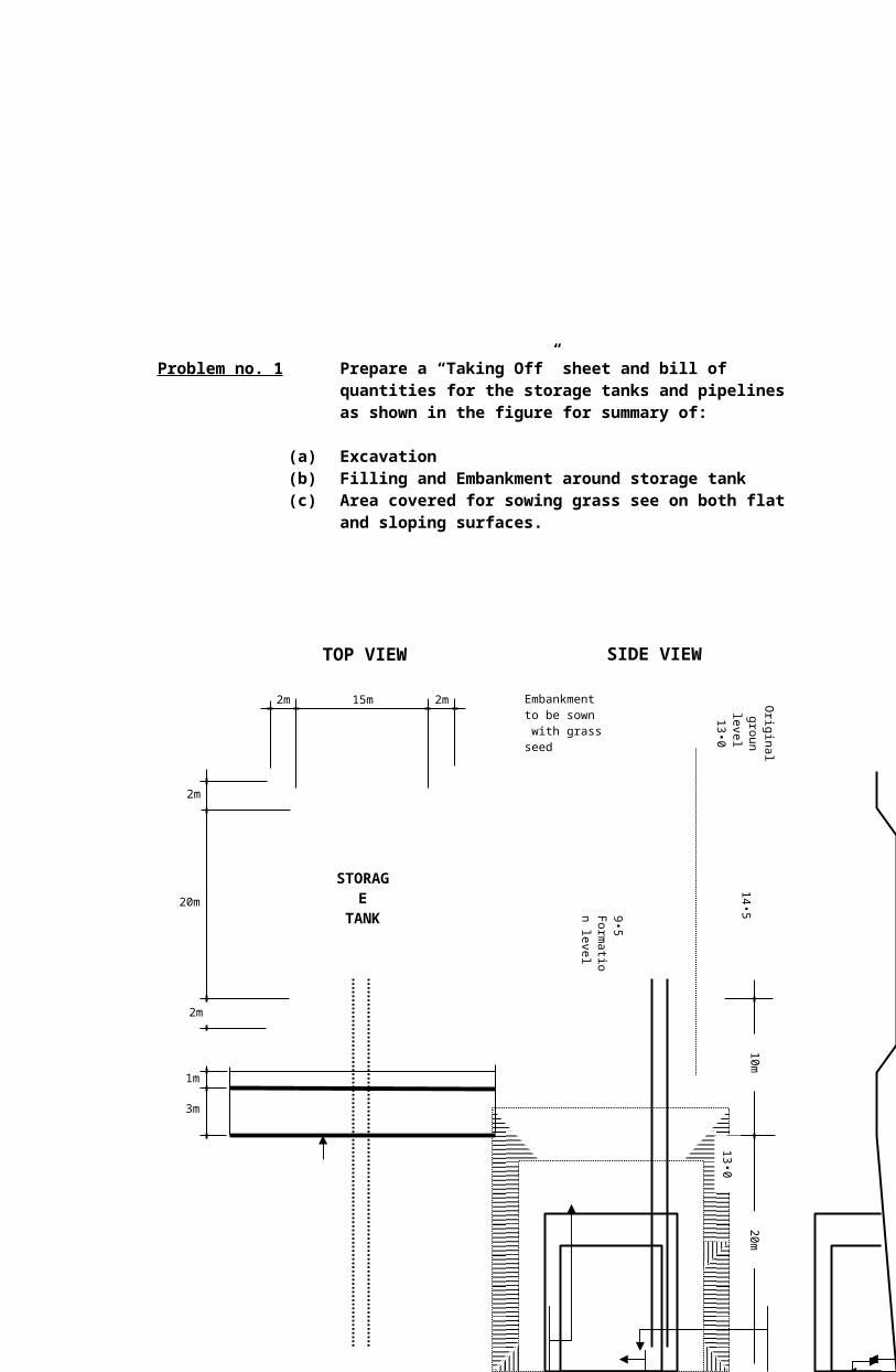
Problem no. 1 Prepare a “Taking Off” sheet and bill of quantities for the storage tanks and pipelinesas shown in the figure for summary of:
(a) Excavation(b) Filling and Embankment around storage tank(c) Area covered for sowing grass see on both flat
and sloping surfaces.
2m 2m15m
2m
20m
2m
1m
3m
STORAGE
TANK
10
m2
0m
10•0
form
atio
n
level
of
trenc
h
14•0
13•0
9•5
Fo
rmatio
n le
vel
14•5
En
d o
f co
ntra
ct
Existing concrete
road, with
Kerbs and
Tarmacadam
footpath
450 mm. DiameterCast iron pipe
TOP VIEW SIDE VIEW
Embankment to be sown with grass seed

Problem no. 2 It is planned to construct a 5.20 meter by 15.60 meter Open Shed with GI roofing, adjoining a present concrete wall as shown. The rafters and roof framing will be of wood and shape to the concrete wall at one end and wooden girts, on the other supported by 6-inch GI lally columns with necessary plates and accessories and anchored to theconcrete slab 5-inch thick (Class B).
Prepared a complete Bill of Materials. Summarize the bill of materials with reference to the “Taking Off” done.
5.20 meters
3 Bays @ 5.20 meters
50 x 100 mm (Purlins)
75 x 150 mm (Girts)
75 x 200 mm (Girts)
Existing Concrete Wall
Straps
7.20 meters (roofing materials)
4.20 m
TOP VIEW
0.30 m 4.90 m
Rafters
Lally Column
125 mm Concrete Slab
Plates
Existin
g C
oncre
te W
all
Pair of Straps
SIDE VIEW


CENTRAL COLLEGES OF THE PHILIPPINES
#52 Aurora Blvd., Quezon City
COLLEGE OF ENGINEERINGCivil Engineering Department
Plate No. 3 Deflection of Structures Backgrounder of Methods
FERRERAS, ARAM A. January 21, 2009
BSCE – 4 / CE 483 Date Accomplished

Objective:To able to state the theory, derive working principles and formulas for each methods used in determination of deflection of structures.
Introduction:
Virtual Work Method:Principle: If a structure in equilibrium under a system of applied
forces is subjected to a system of displacements compatible with the external restraints and the geometry of the structure, the total work done by the applied forces during these external displacements equals the work done by the internal forces, corresponding to the applied forces, during the internal deformations, corresponding to the external displacements.
Conjugate Beam Method:Principle: The conjugate beam method may be used to obtain an
expression for the entire deflection curve over the whole of a structure. The method may also be used to determine fixed-end moments and support reactions in continuous beams and frames, through generally the column analogy and moment distribution methods are preferred methods of solution.
Moment Distribution MethodsPrinciple: Moment distribution is essentially a relaxations until the
desired degree of accuracy has been obtained. This methods method provides a quantitative solution to a problem but may also used to provide a qualitative understanding of structural behavior.
http://www.pdfgeni.com/book/kassimali-3rd-structural-analysis-solutions-pdf.html
http://www.cdeep.iitb.ac.in/nptel/Civil%20Engineering/Structural%20Mechanic%20II/Course_home_4.1.html