theory 14: drawbar performance instrumentation - un … · theory 14: drawbar performance...
TRANSCRIPT

Theory 14: Drawbar Performance Instrumentation
TRAINING ON ANTAM STANDARD CODE
For TESTING OF KNAPSACK MISTERS CUM DUSTERS
2nd Training of Trainers on ANTAM Codes
16 - 28 October2016, Nanjing China
Travel reduction-Slip
Five dimensionless parameters are used to describe tractive performance:
Travel reduction ratio (TRR), commonly called "slip" and expressed in percent.
Net traction ratio (NTR), sometimes called pull/weight ratio.
Tractive efficiency (TE), usually thought of as percent but also used as a ratio.
Gross traction ratio (GTR).
Motion resistance ratio (MRR).

Travel Reduction Ratio (TRR)
t
a
V
V
lvelocityTheoretica
cityActualveloTRR 11
Travel reduction has traditionally been called "slip" or "% slip," but technically this is incorrect. Slip occurs between surfaces. Travel reduction is a reduction in distance traveled and/or speed that occurs because of: Flexing of the tractive device Slip between the surfaces (rubber and concrete, for example) Shear within the soil.

Defining Zero traction
From a power efficiency standpoint, travel reduction is a power loss caused by a loss in travel speed or distance traveled. Slip (travel reduction) occurs any time a wheel or traction device develops pull (net traction) (Brixius and Wismer, 1978).
Zero travel reduction can be defined using any of four methods (ASAE Standards, 2001b):
1. A self-propelled (zero net traction) condition on a non-deforming surface (recommended for rolling circumference data, as in published tire data).
2. A self-propelled (zero net traction) condition on the test surface.
3. A towed (zero gross traction, i.e., zero torque) condition on a non-deforming surface.
4. A towed (zero gross traction) condition on the test surface.


Rolling radius measurement
The rolling radius (rr) measured under zero slip condition is used to calculate the theoretical speed (Vt) of the wheel or tractive device:
The actual forward velocity (Va) of the vehicle or wheel is usually measured directly using a fifth wheel or radar device. Both Vt and Va must use the same units of measurement.
60
2/
rrrpmsmVt

Instrumentation for slip measurement
The angular velocity of the drive wheel can be measured by enCoder
mounted to the wheel axle, coupled to a high speed digital counter.
The actual ground speed is measured using a fifth wheel. The data is fed
into the data logger.

Net Traction Ratio (NTR)
dR
NT
forcereactionDynamic
tractionNetNTR
The net traction ratio or pull/weight, or P/W, dynamic traction ratio, or
coefficient
of traction.
The dynamic reaction force or dynamic weight (Wd) includes the effects of ballast
and any weight transfer that may occur in the testing process.
I a power tiller, The dynamic reaction on the drive wheel alone are to be
considered

Balancing a power tiller without tail wheel
When the test is conducted on a Power tiller, The weight on the drive wheel will be reduced if a tail wheel is included for additional support. When there is no tail wheel, the tiller is balanced by the operator by applying vertical push/ Pull force on the handle. This cannot be quantified. When a pull is applied on the drawbar, the Power tiller without tail wheel will tend to rotate about the axle and loose balance. The operator will balance the moment by the reaction exerted on the handle. Hence the process of measuring the pull developed by the power tiller may introduce unaccounted forces in the measurement system.
When the line of pull is at an axle, it will also introduce vertical component of pull as a dynamic reaction on the drive wheel.

Tractive Efficiency (TE)
powerAxle
VNT
inputPowerAxle
powerOutputDrawbarratioTE
a
)(
t
a
t
a
t
a
V
V
GTR
NTR
V
V
WdGT
WdNT
V
V
GT
NT
/
/WW
a
NT
VNTTE
2
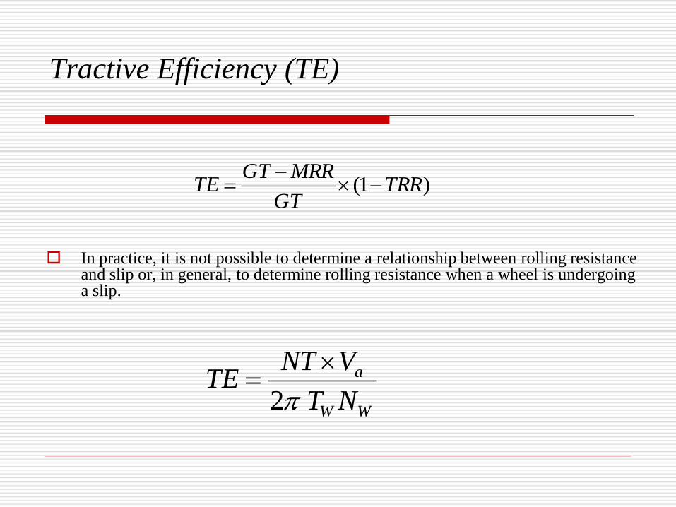
Tractive Efficiency (TE)
In practice, it is not possible to determine a relationship between rolling resistance and slip or, in general, to determine rolling resistance when a wheel is undergoing a slip.
)1( TRRGT
MRRGTTE
WW
a
NT
VNTTE
2

Gross traction (GT) is sometimes referred to as rim pull, design drawbar pull, or
theoretical pull. It is the axle torque input converted to a pull force. It is the pull
that would develop if there were no motion resistance loss.
Wdrt
T
Wd
GTGTR
Note: The gross traction ratio (GTR) is the least understood of the traction parameters. Gross
traction (GT) itself cannot be measured directly and is usually calculated from the axle torque
and radius of the wheel . The problem is that the correct radius to use is not well defined or
directly measurable. There is no general agreement among traction researchers as to what
radius to use, and an alternate method of calculating gross traction ratio is preferred using
energy or power considerations.

Motion Resistance Ratio (MRR)
NTRGTRMRR

Procedure ANTAM-001 2016
The power tiller shall be fitted with pneumatic wheels and the test shall be conducted on a clean, horizontal and dry concrete test track containing a minimum number of joints (IS 993:2002).
The test shall be conducted in running state corresponding to the manufacturer's recommendations.
During the test at drawbar, the governor control shall be set for maximum power at rated engine speed defined by the test (4.4.1.7 OECD Code 2-2014).

The test shall not be conducted in the gear for which the forward speed exceeds the safety limit of the testing equipment.
The test shall be made at least in the speeds, from one giving a travel speed immediately faster than in the gear in which the greatest maximum power is developed down to one immediately slower than the gear setting allowing maximum pull to be developed (4.4.1.7 OECD Code 2-2014).

During the test, the line of pull shall be maintained horizontal. The height of the drawbar shall remain fixed in relation to the power tiller.
At the beginning of the test, the height of the tyre tread bars shall not be less than 65 percent of their height when new. The measurement shall be made at the centre line of the standard tyres (9.2.6 GB/T 6229-2007).
The measurement of drawbar pull, speed and slip shall be started only after the operational conditions are stabilized.
The test shall be conducted for at least 20 m continuously without varying atmospheric or track conditions significantly (9.2.8 GB/T 6229-2007).

Test for Maximum Power and Pull
The test shall be conducted until the maximum power and pull are found in different forward speed gears.
Measurement of engine speed, drawbar pull, fuel consumption, forward speed and wheel slip shall be
recorded (9.3.1 GB/T 6229-2007).
The maximum drawbar pull and drawbar power shall be recorded at power tiller wheel slippage only up
to 15 percent. As the no-slip distance will vary according to the degree of wear of the tyres, it will be
necessary to check this regularly, particularly before determining maximum drawbar power (9.3.1 GB/T
6229-2007).
If the manufacturer/applicant recommends ballasting of the power tiller, the test shall be conducted both
at ballasted and un ballasted condition of the power tiller and the results shall be reported separately.
The data shall be recorded in D-3 and D-9.

D-9 TEST DATA DRAWBAR PERFORMANCE
Test Gear
Number
Used
Travel
Speed
(km/h)
Drawbar
Pull
(kN)
Drawbar
Power
(kW)
Wheel
Slip
(%)
Engine
Speed
(rpm)
Fuel Consumption Specific
Energy
(kWh/1)
Atmospheric Conditions
kg/h g/kWh Temp.(0C) Pressure
(kPa)
Relative
Humidity
(%)
(1) (2) (3) (4) (5) (6) (7) (8) (9) (10) (11) (12) (13)
Maximum
power test
(power tiller
un-
blaste
d)
i)
ii)
iii)