theoretical considerations for a preliminary design …
TRANSCRIPT

NASA TECHNICAL
o,,
|
Zl--
Z
NOTE NASA TN D-1904
THEORETICAL CONSIDERATIONS FOR
A PRELIMINARY DESIGN OF A SOLAR
CELL GENERATOR ON A SATELLITE
by BernardJ. Saint-Jean;
Goddard Space Flight Center,
Greenbelt, Maryland
NATIONAL AERONAUTICSAND SPACE ADMINISTRATION • WASHINGTON, D. C. • SEPTEMBER1963

E _

TECHNICAL NOTE D- 1904
THEORETICAL CONSIDERATIONS FOR A PRELIMINARY DESIGN
OF A SOLAR CELL GENERATOR ON A SATELLITE
By Bernard J. Saint-Jean
Goddard Space Flight Center
Greenbelt, Maryland
NATIONAL AERONAUTICS AND SPACE ADMINISTRATION


THEORETICALCONSIDERATIONSFORA PRELIMINARYDESIGNOFA SOLARCELLGENERATORONA SATELLITE
by
Bernard J. Saint-Jean
Goddard Space Flighl Cenler
SUMMARY
¢zo_6
This report presents the preliminary calculations necessary
for choosing a solar cell generator from the two design types pos-
sible: with solar cells on the satellite skin, or with solar cells on
both sides of independent paddles. For each of those two types,
numerical results of their aspect ratios are included to permit a
direct comparison.


CONTENTS
Summary ..............................................
INTRODUCTION .........................................
General Considerations ...................................
Purpose of Study .......................................
A GENERATOR WITH SOLAR CELLS ON THE SATELLITE SKIN ......
Description of Generator ..................................
Electrical Series-Parallel Connections of the Solar Cells ............
Aspect Ratio Calculation of the Spherical Spinning SateUite's Rings
for a Given Sun Position ..................................
Aspect Ratio Calculation of Any Given Satellite'sParts
as a Function of Sun Position ..............................
Influence of Temperature ..................................
Determination of Electrical Power Output .......................
A GENERATOR WITH SOLAR CELLS ON FOUR
INDEPENDENT PADDLES .................................
Description of Generator ..................................
General Formula for the Aspect Ratio .........................
Discussion of the Two Operating Cases for a Given Position of the Sun . . .
Aspect Ratio Variation During One SatelliteRevolution ..............
Calculation of the Average Value of the Aspect Ratio as a Function
of Sun Position and Extension Angle ..........................
Calculation of the Average Value of the Aspect Ratio Versus Paddle
Extension Angle for Random Variations of SatellitePosition with
Respect to the Sun ......................................
CONCLUSIONS ..........................................
Comparison of the Two Generator Types .......................
Compensating the Bombardment Effects ........................
7
8
10
11
11
12
16
17
24
27
28
28
28
°..
111


THEORETICALCONSIDERATIONSFORA PRELIMINARYDESIGNOF A SOLARCELLGENERATORONA SATELLITE*
by
Bernard J. Saint-Jean t
Goddard Space Flight Center
INTRODUCTION
General Considerations
The primary electrical power generator on a satellite usually consists of a photovoltaic silicon
cell array that directly transforms sun-radiated energy into electrical energy and whose series-
parallel connections determine the electrical characteristics of the generator.
This primary generator is connected to a sealed secondary battery (sometimes two batteries ) so
that, during orbital day, the generator supplies the satellite load and charges the secondary battery
and, during orbital night, this battery alone supplies the load.
For spin-stabilized satellites, if other parameters are not involved, the preliminary design of the
generator may use either solar cells placed directly on the satellite's external surface (skin) or cells
placed on both sides of four independent paddles, extended at the injection time.
In these two design cases, the generator's electrical power is proportional to the sum of sunny
elementary surfaces, each surface being multiplied by the cosine of the angle it makes with sun
direction. This "useful equivalent surface," which represents the sunny-part projection on a
perpendicular-to-sun-direction plane, is a function of:
1. Satellite attitude with respect to sun--that is, the angle _ between the spin axis and the sunline.
2. Generator shape--that is, elementary facet position on the satellite skin in the first case or
external paddle position in the second case.
We can determine the useful variation gap of the angle 0 for launching conditions and the useful
lifetime given if the spin axis is assumed to remain steady.
* A related discussion may be found in "A Method to Optimize the Solar Cell Power Supply for Interplanetary Spacecraft," NASA Technical
Note D-1846 by Grady B. Nichols.
Mr. Saint-Jean is a research engineer in the Satellite Division of the Centre National d'Etudes Spatiales, Paris, France, and was assigned
as a research associate at Goddard Space Flight Center from July 1962 to February 1963-

Purposeof Study
This study includes the following objectives:
1. Calculation of a theoretical formula for the generator's aspect ratio as afunction of the angle _J.
2. Study of some specific problems for both design cases, such as the following:
In thefirst case, determination of the temperature of the generator's various facets and
practical calculation of the output power for any given satellite shape.
In the second case, determination of the aspect ratio variations during one rotation and
calculation of its average value versus sun position and versus paddle extension angle for random
variations of the angle _J.
3. The design, for any useful variation gap of the angle c._,of the facet positioning or the paddle
extension angle that would give optimum electrical power output.
4. Comparison of the advantages of the two possible design choices.
A GENERATORWITH SOLARCELLSON THE SATELLITESKIN
Descriptionof Generator
This first design places silicon solar cells directly on various external surfaces of the satellite.
The generator thus consists of facets symmetrically placed with respect to the spin axis such that
association of each set of facets in the same plane perpendicular to the spin axis may be considered
as an elenlentary ring. All of these rings generally do not cover the satellitets total external sur-
face (Figure 1), since it is necessary to leave some surface area free either for fastening other
elements (experiments, antennas, de-spin mechanism, separation mechanism) or for thermal control
(suitable emissivity and absorptivity paint zones).fl
For a spin-stabilized satellite, the resulting efficiency of the
generator's various parts is variable: first, because the incident
radiation angle depends on the satellite's geometrical shape and
on the sun direction and, second, because vthe generator s different
rings reach different temperatures, changing the cells' basic
efficiency.
Rmgs_ Facets
Figure 1--Rings of solar cells on asatel I i te.
To determine the electrical power output of such a generator,
the electrical connections of the cells in each facet, the influence
of attitude parameters (rings' aspect ratio), and the temperature
effect will be studied herein.

ElectricalSeries-ParallelConnectionsof the Solar Cells
Assume that the number of cells connected in series in each facet corresponds to the average
operating voltage of the entire generator, that facets of the same ring are connected in parallel, and,
finally, that all rings are also connected in parallel (Figure 2).
If the rotation period is assumed to be low with respect to the facets' thermal constant, every
facet of the same ring will reach the same temperature and the output current of a ring will be equal
to the sum of the output currents of "sunny'facets. Then, since the sun direction changes much more
slowly than the rotation angle, the number of sunny facets per ring may be considered as constant.
Therefore, if blocking diodes are placed at each facet output to prevent the current from flowing
through periodically shadowed facets, the output currents from each ring will be proportional to the
aspect ratios of the corresponding rings.
The same reasoning applies to every ring; but, since the temperatures and aspect ratios reached
are different, the generator output power will vary. For instance, for the shadowed facets shown in
Figure 2 (dashed facets in proper shadow), the first ring could deliver the highest current under the
weakest voltage, the second ring could deliver weaker current under higher voltage, and the third
ring nothing at all.
The choice of operating conditions must take into consideration these variations: Operating volt-
age has to be lower than the weakest possible voltage with temperature variations, and operating
current has to be higher than the highest load current (to avoid battery discharge into the satellite
load during orbital day and, in fact, to charge the battery) (Figure 3).
Blocking Diodes Sunny Facets
+
Ringst
+
Converters
Shadowed Facets
w
Battery Regulator
Series-Connected Cells
Figure 2--Electrical diagram of a generator.
Battery
Load
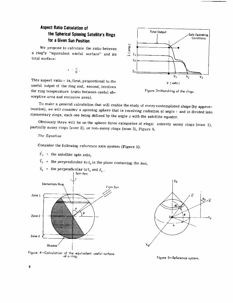
Aspect Ratio Calculation of
the Spherical Spinning Satellite's Rings
for a Given Sun Position
We propose to calculate the ratio between
a ringts "equivalent useful surface" and its
total surface:
2
I2
r S "
This aspect ratio r is, first, proportional to the
useful output of the ring and, second, involves
Total Output_Sate Operating
', _ Conditions
i
I
Yl V2 V3
V ( volts )
the ring temperature (ratio between useful ab-
sorptive area and emissive area).
Figure 3--Matchlng of the rings.
To make a general calculation that will enable the study of every contemplated shape (by approx-
imation), we will consider a spinning sphere that is receiving radiation at angle _' and is divided into
elementary rings, each one being defined by the angle ¢ with the satellite equator.
Obviously there will be on the sphere three categories of rings: entirely sunny rings (zone 1),
partially sunny rings (zone 2), or non-sunny rings (zone 3), Figure 4.
The Equation
Consider the following reference axis system (Figure 5):
Zone 1
Zone 2
Zone 3
O
Xo
= the satellite spin axis,
= the perpendicular to z0in the plane containing the sun,
= the perpendicular toy 0 and Z0
Spin AxisElementary Ring From Sun I Zo
./Figure 4--Calculation of the equivalent useful surface
of a ring. Figure 5--Reference system.

Consider an elementary area dS on one ring, defined by the two angles:
_, = the proper rotation angle,
¢> = the ring latitude,
and let:
= the axial unit vector of the area dS,
Z = the unit vector towards the sun, making the angle :0 with z'0,
R = the sphere radius.
Components of J and _ are
f 0 t f Cos _/, cos ,_
s in i;'0 _{ cos '7' s in ;',
v. cos ,' '0 v_ s in <f,
and the elementary area equals
dS R2 cos .!_.da d__, .
to :(:
Tolal Area of Any Ring
Integrate the expression dS with respect to X, within 0 and 2_:
S : 27TR 2 cos _:. &/ . (1)
Usefid Eqtfivalent Area of Any Ring
Tile elementary useful equivalent area of area dS equals its projection on a plane perpendicular
R2 cos /, d.:\ d/. (cos ,/, sin ;'. sin ('_0 + sin :/ cos (_0)
Removing the integration variable x we obtain:
d_, R 2 cos.: d: (cos :/ six_ _0 sin 7', <t7', + sin,t cos _0 d_.).
Three categories of rings of zones 1, 2, or 3 correspond to different variation limits on _: and to
different integration limits on ,. as follows.

Limits Zone 1 Zone 2 Zone 3
77 77
Variation limits of _ 50 < ¢ < 2- -80 < ¢_< +Co --2 < ¢ < -_0
Integration limits of .k Between
0 and 2 77
t_n¢Between Arc sin
tan ¢
and _ + _rc .sin tm-a _0
Between 0 and 0
(_-- o)
For Zone 1, then,
_r: R2 cos <_de (cos sin8 0 sin L d,\ + sin _cos-_o dX ,
or
For Zone 2,
Cr =
= 2_R 2 cos _ sin ¢ cos 8 0 d_.
sin ,\ d_ + sin ¢ cos 8 o dk ,tsn _ tan ;b
Arc sin tar_ 0-_- Arc sin t-an _9_--_
(2)
or
: 2R2 cos ¢ d,/
For Zone 3, obviously
I ( tan ¢_cos 4_ sin 8 0cos Arc sin tan ¢?o ] _ sin _ cos _Jo(2]
+ Arc sin tan 0 0 ]__(3)
_ : o. (4)
Aspect Ratio Values for the Three Ring Categories
If Equations (2), (3), and (4) are divided by (1), analytical formulas of the aspect ratio are obtained
for a given sun position _o versus the angle ¢, which defines the ring's position:
' 0 -- -- Z '
-0o -< _ <- _o :
r
77
--E_ <--% :
r = sin _ cos _o '
1 tan¢ _ 5 0 + Arc sin tan--5_--_0 ] J= -_ cos¢ sin_o cos Arc sin tan--_-_0] + sind_ cos
r = 0 .
(5)

Since the variable + was not integrated during the calculations, we can consider those formulas as
valid not only for elementary rings but also for thefinite or infinile areas that envelop those rings,
that is, planes (4 = 90°), cones (0 ° < ¢ < 90°), and cylinders (4 = 0°).
Aspect RatioCalculationof AnyGivenSatellite's Parts as a Functionof SunPosition
We consider now a given satellite shape, for which each part corresponds to a given value of the
angle _o (Figure 6).
To determine the aspect ratio value of one satellite part versus the sun position, we contemplate
% as fixed and .:_ as variable in Equations (5).
to between 0 and 90 degrees, we thus obtain
¢o-< ¢;-< 180° - ¢0 :
r : sin +o cos 0 ,
( tanr - -_- :os 4'o sin _) cos Arc sin tan 0 s sin 4o
180°- Yo -< U < Go :
r = 0 .
tan o)1cos t') -_-4 Arc sin
> (6)
If we analyze the physical phenomena corresponding, for example, to the upper frustum of a cone's
external surface, the first formula indicates that all this surface is sunny, the second formula that
only one part is sunny (the two shadow generatrices
move as _ varies), and the third formula that all this
surface is shadowed (Figure 7).
Figure 8 presents the results of Equations (6),
obtained with the help of the Advanced Orbital Pro-
gramming Branch of Goddard Space Flight Center
(GSFC). This plot gives the aspect ratio values cor-
respondiTtg to ten values of Go (0, 10, 20, 30, 40, 50,
60, 70, 80, and 90 degrees), for all sun positions (o
varies between 0 and 180 degrees).
For each curve, the value _ = % corresponds to
shadow occurrence and the value _ = 180 ° - 4o cor-
responds to complete shadow (no aspect ratio). For
instance, a truncated conical surface opened at 30
FromSun Plane (¢'o = 90= )
otCone
(¢o = o°)
Frustum of Cone (¢o = 60")
Figure 6--Shadowing of a satellite.
7

degrees, lighted by rays making an angle of 40 degrees with its axis, will have a theoretical
efficiency of r = 41.25 percent.
Influence of Temperature
The facet's elementary cell efficiency is afunction of the temperature ;,( T ) as approximately
shown in Figure 9.
Therefore, we must consider atemperature correction coefficient to obtain the efficiency of an
operating ring:
r._ :,(T) , r .
One calculation of ring temperature results from considerations of thermal equilibrium between the
energy received and the energy radiated.
This temperature can be determined approximately by considering only the radiati(ms received
from the sun and the earth and by neglecting the conduction, convection, and absorptivity variation
with incidence:
T 4 - "_ ,,C 1 _ r. C 2 + - C_ ,
with the following notations:
T - the equilibrium temperature,
5.67 × 10 .8 watt/m2/ C 4 (Stefan-Boltzmaml constant),
f = part of incident energy converted to electrical energy by the cells,
r = the ring aspect ratio with respect to the sun (angle _ between solar radiation and spin axis),
7r
O< 0<¢ o ¢o < 0< _ _ < O< rr-¢o rr-¢o<0 < _r
Figure 7--Movlng of the shadow generatrices.

L__i_,i_!iiil_:_iI!i!_i_!i_!i!li_i:l!i!,_:_ii!:!i!I_!iii!!iI_!_lli:_ili_!iI!__-
i!_!"i,o, !!iil_;_!;;;_".i'.i,,_;';lY!,J
iii'i !:ii[!iiii!iiii:! i!:i::!L!i : :!, ,::i_
_oi!iitii:_is:i!_s:._ti!:!i_ _:!::': s!: i!!!!i!: !_: !!:;i:_+!i_i:i!i!;:i_:
i o
ealV lel°l OIJ.VI:I/O3dSV
,w-
0 _-0Q.
0
P._
_._ tl/
• 0
°--
Q- O)
0
,-'§o_
...c "0
o_0 0
-- 0
o _
o" CO
.,_ O)
;.__
x_
._ >._ "0

H Isc_E
L.
0 °C)
VocVoltage ( volts )
Isc
._ lOO%
i i....0 30 40 50
T(°C)
Figure 9--Temperature influence. (Isc, Ishort circuit; Voc, V0pen circuit')
% = the ring aspect ratio with respect to the earth (angle _:_ between earth radiation and spin
axis),
C_ = 1400 watt/m 2 = direct solar radiation, integrated as a function of wavelength,
c_ = 160 watt/m s = solar radiation reflected by the earth (albedo),
c s = 140 watt/m 2 = direct earth radiation, integrated as a function of wavelength,
% = the ring's average absorptivity for sun radiation,
% = the ring's average absorptivity for earth radiation,
= the ring's average emissivity.
In the previous formula, calculation is made step by step since _ and f, which are related to the
cells' efficiency v(T), are variable with the temperature.
Determinationof ElectricalPower Output
For a given satellite shape (Figure 10), the generator's total output is obtained by adding the
outputs delivered by each ring:
Pwatts : _ (k i x r i × _i i watt/cm 2 × SL cm2),
i
in which
i = a summation index (for the different rings),
k, = a coefficient for electrical losses,
r_ = the index i ring aspect ratio,
_ = the cells' efficiency in space at temperature T,
S_ = the total surface of index i ring cells.
So we will obtain the generator's electrical output ver-
sus sun position for the sunny part of the orbit. Then, to
Sun
radiation of ringFigure l O--Angilne_:: i"
10

determinetheaverageoutputavailablefor the load, wewill considertheorbit shadowpercentageandthebatterychargerate.
A GENERATOR WITH SOLAR CELLS ON FOURINDEPENDENT PADDLES
Description of Generator
In the second generator design, solar cells are placed on four paddles, independent of the
satellite structure (Figure 11). These paddles are attached to the structure by means of coupled
shafts and are extended at the injection time with a timer command. They are almost plane, with
cells on both sides.
Paddle Positioning
The extension of paddles results from the motion of shafts, which may be complicated by the
space available under the nose cone; but the final position of each paddle depends, practically, on
only one angle, the angle ¢ between the axial vector g of the
paddle and the spin axis. A rotation of each paddle around
its axial vector does not involve its aspect ratio, that is, its
electrical efficiency.
Generally, the four paddles are placed 90 degrees one
from each other, so that their corresponding angles ¢ are
all equal (¢1 : ¢2 ¢3 : % )" During the spinning motion
of the satellite, they will therefore occupy successively co-
incident positions. From an analytical standpoint, the pe-
riod of the output function will be divided by the number of
paddles; for four paddles, it will equal _/2.
FromSun
<
Spin Axis
Envelope of the Paddles lhzring Spin Motion Figure ] ]--Paddle generator.
During the spin motion of the satellite, the infinite
planes that prolong the paddles will remain tangent to a cone
having for its axis the spin axis of the satellite.
Let z be the spin axis, (P) the infinite plane that con-
tains one paddle, _" theprojectionof z on (P), and _, the point
intersected by z on (P) , Figure 12.
The angle _ = _/2 - ¢ between z and _ being constant,
the path of _ will be a cone whose apex is_,, whose axis
is z, and whose half apex angle is _. This straight line
z is the contact slant height between (P) and the cone. Since
the four planes intersect z at the same point _,--if the centers
$
Paddle
/Figure 12--Paddle cone envelope.
11

of the paddles are in the same plane perpendicular to the spill axis, then their envelope will be
this cone.
Figure 13 shows a view of four paddles and their cone envelope in a general case.
GeneralFormulafor the Aspect Ratio
The voltaje of this generator is determined mainly by the number of cells coimected in series
and by the operating temperature. Since the four extension angles ,_ are assumed to be equal, we
can admit that the temperature of the four paddles is the same. Since the number of cells connected in
series on each paddle is chosen to be the same, and since the four paddles are connected in parallel, the
current output of the generator will be proportional to the sum of the aspect ratios of the four paddles.
We will first establish a general formula for this aspect ratio as a function of the extension an-
gle ; of the paddles, of the position of the sun (angle _,between solar rays and spin axis), and of time,
for a spin rate _, (proper rotation angle .x_= _.t).
Shadotc Problems
For certain positions of the sun with respect to the satellite structure, projected shadow prob-
lems and self shadow problems occur.
1. Self shadow
Solar cells are placed on both sides of eachpaddle. Nevertheless, only one side will be sunny
at any given time. Over one complete revolution of the satellite, it might be always the same side, or
alternately one and then the other (to be discussed on p. 16).
2. Projected shadow (Figure 14)
Depending on the geometrical shapes and the positions of the structure and the paddles, four
cones can be defined to study these problems:
For the shadow projected by the structure on the paddles, the two half apexangles are % and %:
0 ° < _ < ,q : no shadow
,q < _, < % : shadow
:2 .... 180°: no shadow
For the shadow projected by one paddle on another, the two half apex angles are ,_ and /32:
0 ° < c; < ,._ : no shadow
_ < _; < /32 : shadow
/_2 < t; < 180°: no shadow
12

\
Figure 13--Viewof the paddles and the cone they envelop in their movementaround the spin axis (descriptive drawing).
13
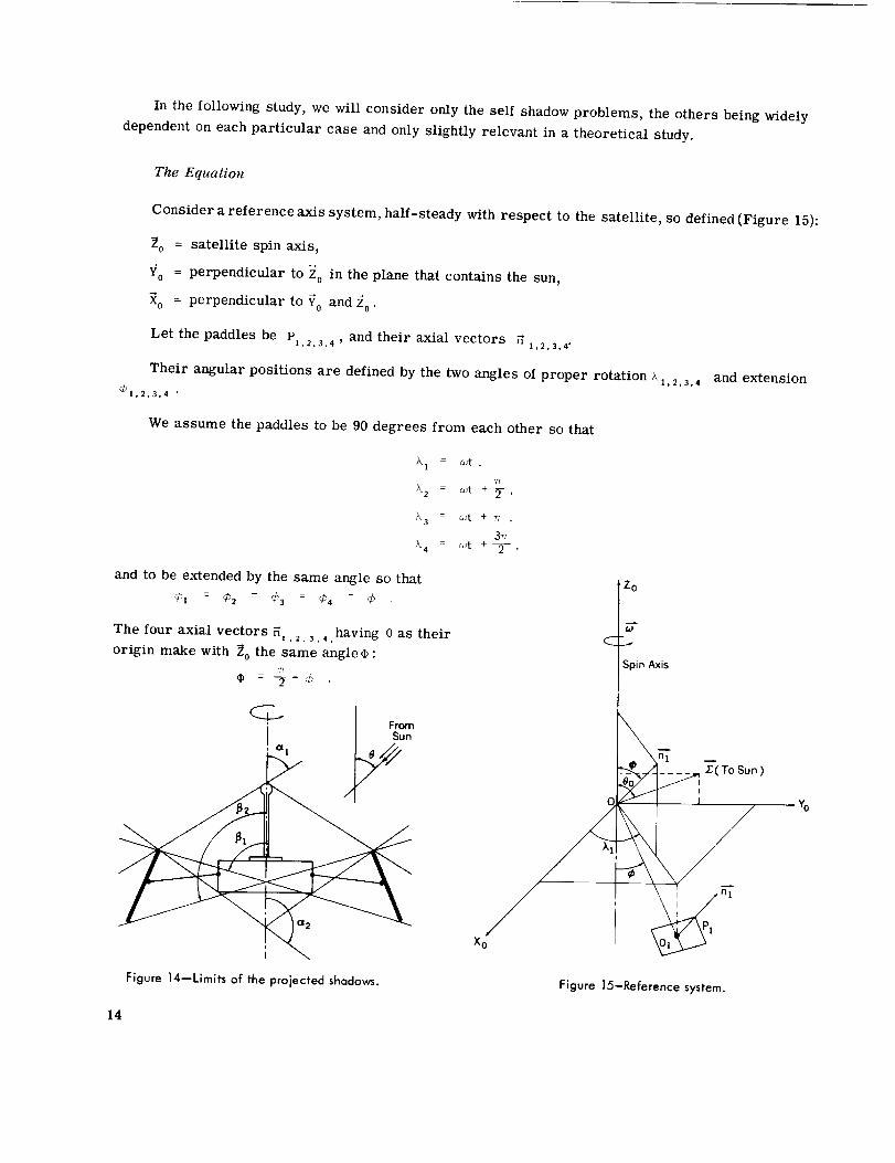
In the following study, we will consider only the self shadow problems, the others being widely
dependent on each particular case and only slightly relevant in a theoretical study.
The Equation
Consider a reference axis system, half-steady with respect to the satellite, so defined (Figure 15):
20 = satellite spin axis,
Yo = perpendicular to Zo
Xo = perpendicular to T o
in the plane that contains the sun,
and z0"
Let the paddles be P1,2,3,4 ' and their axial vectors _ 1,2,3,4-
Their angular positions are defined by the two angles of proper rotation _1,2,3,4
_1.2.3.4 •
and extension
We assume the paddles to be 90 degrees from each other so that
)k I = o_t ,
7/
L 2 = wt + _- ,
'_3 = _'t + _; ,37r
L4 = _t +T '
and to be extended by the same angle so that
¢, = ¢_ = ¢s : r¢'4 : ¢
The four axial vectors 3,. _. 3., .having 0 as their
origin make with 2 o the same angle¢ :
q_ = -_- _
C [/ Sun
Figure 14--Limits of the projected shadows.
Z0
CL,.
SpinAxis
z'-(ToSun)
Xo _l
Figure ]5-Reference system.
-Yo
14

The unit solar vector is _, in the plane V0Z0, making with z0 the angle 8 0 . Its components are:
I 0sin _o
cos 8 0
Assume the initial time t = 0 to be the time when the axial vector _ of Pz is parallel to the plane
X0Z 0 (or directly in this plane). At any time t, the axial vector components will therefore be
{os co:co¢t {co¢cotto¢tH 1 cos ¢ sin a;t H 2 cos ¢ cos _*t n3 -cos ¢ sin cot na -cos ¢ cos _t
sin 4' _sin ¢ sin ¢ ,sin
Let s be the surface of one side of the paddles. The total surface of the cells of the generator is
the r efo r e
S = 8S .total
The "useful equivalent surface" _ of each paddle is equal to the projection of the sunny side on a
plane perpendicular to the sun direction:
In fact we have to contemplate the modulus of the
former function, for both sides are involved in fur-
nishing current. A negative value of c_ corresponds to
a current identical to the one that would be furnished
by the other side, but positive.
Figure 16 represents the real value of _, the value
of c_ for apaddle having cells only on one side, and the
value of _ for a paddle having cells on both sides.
Thus we will consider
For the complete generator, the "useful equivalent
area" is
and the aspect ratio is
O-tota / I _', " _ " + / _2 " _ 1 + '] _3 ° _ I + I a4 . Z ,'
r - Stotal 8 '
(o)1 side
(o)2 sides
t
i
JI
Figure 16--Possible values of_.
,t
,t
-t
15

whose analytical expression is
1r g-[I sin ,_ cos _/, sin-:'t ÷ cos .!; sin 4 _ I + ! sin _ cos ,:_ cos _:ot 4 cos _? sin ;_ I
+ I-sin '.' cos ,¢_ sin c,:t + cos ,4 sin :_ i + [-sin ei cos :¢ cos <,,t + cos _," sin 4' 1] •
(7)
Discussionof the Two OperatingCases for a GivenPositionof the Sun
Each one of the four terms of r is a sine function of time, whose mean value is
cos i; o sin c++
and whose amplitude is
sin "!0 cos 4' -
The analytical corresponding forms of these terms are to be changed by their opposites when the
amplitude is superior to the mean value, that is, when
If we limit the variations to
the condition may be written
sin 0 0 cos ,)6 > cos 0 o sin ¢
?7
0<_ o <-_
0<¢<_,
or
tan
tan _0 2 1
0<,¢:_< _40 .
Accordingly, there are two operating cases, depending on the value of the extension angle ,_ with re-
spect to the value of the sun ray angle _'0 (Figure 17).
1st Case, '0 <- ¢ -< -'v2:
The aspect ratio curve for each paddle does nol cut the _,t axis, which means that only one side
of the paddle is sunny while the other side is always shadowed.
In this case the moduli are not involved, and the generator aspect ratio remains constant during
the rotation. (The analytical study is given in the next section.)
16

r r
For 1 paddle For 1 paddle
, , AmplitudeI i
I Mean Value
lr 27r wt
f _ '_ _ J Amplitude
....... __-_---.= Mean Value
Ul "-_** U2 27r
1_ side 2 --I
(a) 1st case: _;o -< +! 7r,2 (b) 2nd case: 0_< _"- !'0
Figure 17--The two operating cases.
2nd Cas%o _ /, < :
The aspect ratio curve for each paddle cuts the _,:t axis, which means that each side of the paddle
is alternately sunny. We then must consider the moduli; and the aspect ratio is not constant during
the rotation.
For paddle P,, for instance:
If o:t is in the interval uj, u2:
If _t is out of the interval ul, u 2 :
(The analytical study is given below.)
[ Ii r [ -r
Pl Pl
IF l_r
Pl Pl
It should be noted that the physical operation of the generator corresponding to these two cases
can be explained geometrically (Figure 18). The cone enveloped by the paddles during their move-
ment has a half apex angle ¢, and the solar vector _ makes an angle _0 with the spin axis. So the
cases correspond to the fact that the vector Y is inside the cone in the first case (% _< ¢ : _,"2)two
and outside tile cone in the second case ,[°!¢ _ ,_o_.1
!
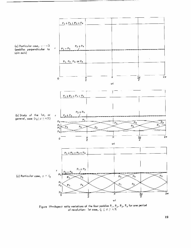
Aspect Ratio Variation During One Satellite Revolution
Consider the angle J_o as given, the angle _t, as a parameter, and the proper rotation angle _ .:.:t
as the variable. We will study the shapes of the aspect ratios r of the four paddles Pt, P2, P3, P4 ;
their sum two by two P1 + P3 , P2 _ P4; and then their complete sum P_ + P2 + P3 * P4 (Figures 19
and 20).
17

(a) 1st case: _o -< _<- _/2
Z
(b) 2nd case: 0 < ¢< 8o
Figure 18--Geometrical explanation of the two cases.
Study of the 1st case, 8 0 _< ¢ _< _/2:
The analytical formula of r is, in this case,
1 (rplr - 8 + rp 2 + Tp3 + Fp4 /
with
r = sin 8 o cos ¢ sin _t + cos 8 0 sin ¢ .Pl
= sin 8 0 cos ¢ cos wt + cos _0 sin ¢ .rp2
rps -sin 8 o cos ¢ sin wt + cos 8 0 sin q5 ,
rp4 = -sin 8 o cos q_ cos wt + COS 0 0 sin _b
Each term rpt , rp2 , rp3 , rp, is represented by a sine curve that does not cut the _t axis. The par-
tial sums P_ + Ps, P2 + P4 are represented by straight lines; and the general sum P_ + P2 + P3 + P4
is represented by a straight line:
1r = _-cos 8 0 sin ¢ .
Figure 19(b) shows this general case.
Figure 19(a) represents the particular case ¢ = 77/2, which corresponds to paddles perpendicular
to the spin axis (the aspect ratios are all constant).
18 °
(a) Particular case, _ -_;2
(paddies perpendicular to
spin axls)
P1 + P2 + P3 + P4
P2 + P4
P_ + Ps [___.
Pl, P2, P3, or P4
0 _r _ 3Tr 2rrT
(at
7P1 + P2 + P3 + P4
(b) Study o_: the ]st, or
general, case (_0C_ 2 _/2 )
i
P2 -}- P4A___ !
P3
P4
0 7r 7r 3rr 2tr--Z
_t
(c) Particular case, _ : 9o
PI +P2+P3+ P4
PI +P3P2 + P4 /
_ ._/_ _ _
P4
0 7r tt 3.___2
_t
Figure 19--Aspect ratio variations of the four paddles P], P2, P3, P4 for one period
of revolution: 1st case, _0 <- _ < _/2.
27r
19

_°
U
--U
I141
I I
PI+P2+P3+_
r)
I
III
f
P3 P4
7r 7r 2rr2
II
U3 ! U32 U21 U22 U 11 U 12 U42
(at
"rT(a) For _- < u - Arc sin _ <-_-tan /J0 2
P1
P3
P4
P2 nLp4
P2_
U
V= _'-- U
I 1
I II I
E2
I
II
37r
2
U41 U32 U!
U31 U21 U22
(12 1
U42
_t
tan q# zr(b) For u =Arc sin tan 0O 4
Figure 20--Aspect ratlovariatlonsof the four paddles P1, P2, P3, P4 for one period of revolution: 2nd case, 0 < r_ <00.
2O

P2
P4
PtP3
/
U31 U41 U21 U32 U 11 U22 U42 U 12
_t
fan / ,_,'
(c) For 0 < u Arc sin :a_,::7 ' 4T n 0
P4
P2
U31
I I I I
,,"1\ / "- i , \ t / \ t
,_,__'--\ _ /;_.__'\ i ./_"__\ i /__ ', I
.......... -..... J ..................... _l.......... "...................................v-_ _ i
U21 Ull U22 U12
U41 U32 U42
t a n r/
(d) For ¢: = 0 (u : Arc sin tan _;;0 0), paddles parallel to spin axis
Figure 20(Concluded)--Aspect ratio variations for the four paddles P1 , P2, P3• P4 for one period of revolution:2nd case, 0_ _/ 5 'i0"
21

Figure 19(c) gives the particular case ¢ = _0, which corresponds to paddles whose cone envelope
has one slant height parallel to the solar rays. The aspect ratios equal zero for only one value of _t,
but the second side still is not sunny.
Study of the 2nd case, 0 _< ¢ _< o0 :
The moduli must be considered in this case. Let us calculate first the two values of _.t cor-
responding to the sign change and defining the sunny side change. If we call u a_d v the main
determinations as follows,
tan@_ l
u = Are sin tan 8 o77
0<u,v<_-,tanqb
v = Are cos tan 8 0
the values are, respectively,
For paddle P,,
tan ¢/ f 1st value: Ull : 7 + u ,_t 1 = arc sin (- tan 8o/ 2nd value: u12 = 2_ - u ;
For paddle P2,
tan _ )_t_ : arc cos - f 7
1 st value: u21 - 2 + u = _ - v ,
3772 nd value: u22 - 2 - u = 7 - v ;
For paddle P3, [ tan ¢ ) ; 1st value: u31 : u ,_t 3 = arc sin _ta--_° _. 2 nd value: u32 = v - u ;
For paddle P,,
tan _ ) 1 _t value: u4! = _ - u = v ,_t 4 : arc cos \t_n_00 37r
2 nd value: u42 2 + u = 2n - v .
So, these eight values uu, u_2, u_, u22 , Ua_ , %2, u4, , and u4_ must be sorted by order of increasingtan
values and the two cases distinguished according to the value of u = Arc sin tan _?------_with respect
to 7/4. The shapes of the curves will be different in the two following cases:
1. For 0 < u = Arc sin tan _0 < 4- Figure 20(c :
The complete aspect ratio P1 + P2 + P3 + P4 has a wave shape of period _/2 involving two different
parts of sine functions. The corresponding analytical formulas, given in Table 1, change at each of
the eight former discontinuity points.
7 tan qb 72. For _ < u = Arc sin tan 80 < _- [Figure 20(a)]:
The complete aspect ratio has a wave shape of period 7/2 but involves only one sine function, the
other part of the curve being constant. The corresponding analytical formulas are given in Table 2.
Likewise, two particular cases are given on page 24.
22

vl
II
v _
o
v1
vi
I
p E
I
_I_
vL
vl
v1
o
c._
J
U
I-
I-
+
c
8u
°_
c-0_
8u
+
_Rc°_
u
¢-0_
+
u
°_
+
u
8u
+
8U
8U
I
o_
8u
I-._
%
I
°_
8u
°_
+
i-
u
i_
I-
+
8U
c
u
E
I,-
V1
.I.-
.c_
H
vi
vl
v
vl
!
I
vl
vl
0
+
i-
8u
U
I-
i-
F------I I
¢-°--
U
+
8U
.c_
-I_
C
8U
i--°-
U c0
+ _g
8 NU
23

ta, ,: T; [Figure 20(b)] :1. For u Art- sin tan _'o '+
The aspect ratio curve in this ease is symmetrical; this corresponds to the fact that the second side
of the paddies is sunny exactly one-fourth the time of revolution.
tan ,t,: 0 [Figure 20(d)] :2. For u Arc sin tan '_'0
The aspect ratio curve still has a symmetrical shape, but the ratio between the maximum and the
minimum is higher in this case. The paddles are parallel to the spin axis, and each side is sunny
exactly one-half of the time.
Calculationof the Average Value of the Aspect Ratio
as a Functionof Sun Position andExtensionAngle
This study of the paddle generator is chiefly interesting in regard to the ratio between the max-
imum and the minimum of the generator's current output during one period. This effectively involves
the performance of the converters.
Nevertheless, Ihe avcvag'e power otttDHl over a long period of time is the very significant pa-
rameter of any preliminary design.
We will calculate this average value of the aspect ratio as a function of the two angles _,, (paddle
extension) and :_0(sun position), assuming that the spin rate _, is constant. The average value of r is
given by the tormula
r m r(>,_) d>,, with :..... ,,t .
1st Case, _o i ':' < _ :
We previously noted that the aspect ratio was constant in this case, so its average value is equal
to its value
1r -2 cos(! 0 sin _[: .
2nd Case, 0 :: :, : o :
We have to consider the following two cases:
l?
1. For o i u < 2, from Table 1:
or
F m
1I" m
si, i cos ) d>1
24

2. For _ _<u -<2, from Table2:
or
r m1 "T-U(sin '20 cos 4-' cos :_. + cos _0 sin ¢,) d). * 27,
) 2 U
7cos '_0 sin "/:, d> /
( ]
r m _ in "_o cos :¢, cos u _ u cos (t 0 sin (/.
So, if we consider the sun position as steady with respect to the spin axis (angle "0), the average
value of the aspect ratio as a function of extension angle ,/ is given by
0 < _ 2 %:
7"
I?o < < -_
Ic ( tan:7. _ 4 !t 0 "ta_l"+" _rm _ 71 os d: sin ")o cos Arc sin -_tan !::'0)+ sin cos Arc sin tan i)0] '
1
r : 2- sin 4 cos _')0
> (8)
Otherwise, if we consider the paddle position as steady with respect to the spin axis (angle 4o), the
aspect ratio average value as a function of the sun's position is given by
0 < 5_ < _0:
r
m 1
7,
1
: _- sin c_o cos e) ,
-- -- - ';'"0rrn2 "7 cos 4_o sin i; cos Arc sin tan_) ]* sin '-' cos 'J Arc sin tan¢.' '
It should be noted that in Equations (8) and (9) the two variables ,+ and play the same part.
if we change ¢ by _,/2 - u,
useful for the other group).
(9)
Indeed,
they do not change. So, we make a plot of just one of them (and it will be
Figure 21 gives the computed results of Equations (9), obtained with the help of the Advanced
Orbital Programming Branch, GSFC. This plot gives the aspect ratio average value r corresponding
to ten values of q_ - r_/2 - 4 (0, I0, 20, 30, 40, 50, 60, 70, 80, and 90 degrees), for all the positions
of the sun between 0 and 180 degrees.
For each curve, at the value q, : 90 ° - % the generator starts to behave as in the second case,
with two sides alternately sunny.
For instance, a generator whose paddles make a 40 degree angle with the spin axis (that is,
¢ ' 50 degrees), and sunlit by rays making an 80 degree angle with the spin axis, will have an aver-
age efficiency of r m : 24.3 percent. This plot may be useful when the useful interval of ¢', during the
lifetime of the satellite (which can be deduced from the launching conditions) is known, in order to
get the variation of the power output as a function of time.
25

26
_:<tt
_:_+,
,+
!i
;!I
:II
,If
I;!
i:1
:t;
I:
ff_t
It
_J
_t
;&
:it: t r..¢¢'. ._t .... '.L
;_ 4 ;_+++717: c_1 ,, , _, tl• ,t. 47
t_ ........ i7
:2 :++++:++.+:I:++I+:
rTT: T+!! !7
] 2i;: ;:4_ 4:
.... 4_
1 1'.'+_ l_',l i i
,I .f+. +-.*, _+
H:_-i 1i17 7TII !iJ_ _;:++ _+:,, ++4 ++_+ "'+* +'
; ,iu f!!! i:.iT ......... }i_+.+ +÷.÷
• _ ::4: }[4-.-
- [,4i i;
:!; !i
@ _'g+i i_ii "_
4+_21
•1 i!i!:_i: ,i
_i4 i !
:1 :ii: ;:!: +,:
i: . ......!__j li_i !i!i :_J; 717
',! i,:i ii:i
",_ -t I ' t_i,
ii !:r
; _? L+I+!:
= L_+_Ftt¢t
d _
Zw"n..aZO_zto_
$
i;!
£
:11!r!
iF
:!4 _I
o
ll) "0
0 0
'*- -0
o8.
o_
°_8
r- I1 _I1 _ °-
7!7
0
*_ °_
_.--_N B
_ °_
°_
o o._'=8
°-
"_-_ ;
0
_ Pdx
_, &.__.

Calculationof the AverageValueof the Aspect RatioVersusPaddleExtensionAngle
for RandomVariationsof Satellite Positionwith Respectto the Sun
The variations of the aspect ratio's average value when the satellite is not well stabilized (for
example, if a precession occurs, or if the de-spin mechanism does not work correctly) are of inter-
est. Assume the different angles _ representing the sun rays to be equally distributed, which means
they take all the possible values between 0 and 180 degrees with equal probabilities. We will analyt-
ically study the mean value r m as a function of ¢ only and then determine whether a value of, exists
for which_mhas a maximum. For all the possible values of _, the generator will work partly in the
first ease and partly in the second ease; as an average, we will have:
- 2 _o
r -_ rmj d_ + r 2 d_¢o
E£ 12
-r -- _- 7 (sin _ cos ¢0 cos u + u cos _ sin Co) dO + cos 0 sin ¢0 ds
o
_ sin 2 q5o 2 "g tan _5o
rm - _7 + _ J¢0 cos q% sin _ cos Arc sin tan _3 J + sin60cos _3 Arc sin --tan t? d0 .
This mean value rm, which is a function only of the extension angle ¢0, has been computed with the
help of the Advanced Orbital Programming Branch, GSFC.
The results are shown in Figure 22. It appears that r does not have an optimum other than 90
degrees between 0 and 90 degrees; it is an increasing function of %. For a badly stabilized satellite,
0.35
0.30 _'
_-m
0.25
O.20 o
1
i10
_-FFFFT q-i-F
_-+_-
T?T
20 30
PADDLES PARALLEL TO THE SPIN AXIS
4O
¢o ( degrees )
90
PADDLES PERPENDICULAR TO THE SPIN AXIS
Figure 22--Average aspect ratlo of a paddle generator for random variations of the spin axis with respect to the sun.
27

and if we forget the "maxi-mini" problems, the best design is to place the paddles perpendicular to
the spin axis. By so doing, the average efficiency is r m Z:_ - 31.8 percent.
CONCLUSIONS
Comparison of the Two Generator Types
The differences between the two possible designs are the following:
1. Free room inside the nose cone: For a given size of satellite, the first design {cells on skin)
takes less room and might even weigh less than the second design.
2. Electrical power output: In both cases, the aspect ratio is a function of time. The first de-
sign (cells on skin) is better suited to the constancy of the output, as far as we can choose the shape
of the satellite. The second design (cells on paddles) leads to bigger maxi-mini ratios but has the
advantage of being more adaptable to design changes. An exact comparison can be made on the two
plots shown in Figures 8 and 21.
3. Shadow: For projected shadows, the first design (cells on skin)is better. For the self shadow
phenomenon, the two designs are comparable.
4. Temperature: The second design (cells on paddles} is better provided the paddles are ex-
tended at the same angle.
5. Handling_ tests, countdown: The second design (cells on paddles) is better.
6. Free windows on the structure of the satellite: If free surface areas are needed on the faces
of the structure, the second design (cells on paddles) seems better. It is difficult in this case to de-
sign the generator symmetrically with cells on skin, and even so this might result in an inadequate
power supply.
Compensating the Bombardment Effects
After launch, the solar cells' electrical characteristics are _fected by particle bombardment
(protons, electrons, micrometeorites). If we can deduce the damage time rate (from the particular
orbit, the intensity of the beams, and the particle energy) and if we know the aspect ratio variations
(from angle _ variations}, it is possible to choose the launching conditions (time, azimuthal speed} to
compensate this damage, that is, to start the lifetime at a point for which the aspect ratio would
increase at the right speed.
28 NASA-L,,,,_,:, _,_3G-443

