thejournal of gear manufa'cturing · thejournal of gear manufa'cturing september/october...
TRANSCRIPT
The Journal of Gear Manufa'cturingSEPTEMBER/OCTOBER '987
Tooth Thickn'ess Measurem'entsS,ele'ctionof ,Proper Ball Size to' ,Check
an Invol'ut,e or H,elica'iGea'rEffects of Quality & R'esharpening Errors
on Generating AccuracyS.IUnits - Measure.ments & Equivalencies


Accurate gear inspection depends on repeatable machinedata evaluation. Profit depends on speed. Maag CNC gear measuring eel_tilthree, in the lab and on the shop floor.• Maag mechanical machines combine the speed and automatic checking of CNC withthe reliability of a base circle disc design for profile and lead gear inspection.• Only Maag mufti-axis electronic machines measure internal and external spur, helicaland duster gears with up to 15 sets of teeth, all ina single setup, with accuracy of.000040'&n.• Maag's unique easy-to-use menu programming and software aurornattcally bring thestylus to the tooth surface.If you'd Iike to know how to spot your bad apples quicker, contact American Pfauter,925 Estes Ave., Elk Grove VHlage,IL60007. Phone (312) 640~7500.

Says Quality Has toCost More?We Don't! New Angle Gear produces precision, hard finished
spiral bevel gearing, at cut and lapped prices.Utilizing the Klingelnberg HPG·S method, state-
of-the-art equipment delivers spiral bevel gears upto 30 inches diameter, at AGMA Levels 10-13.AndNew Angle gears accommodate higher loads(torque) with "whisper" quiet operation. Or ... youmay opt to reduce gear size to further reduce cost.
Also, matched sets are a thing of the past withour process of proven repeatabi Iity.
Our FREE quick facts brochure cantell you a lot more ... Write or Call:
CIRCLE A-3 ON READER REPLYCARD
NEW ANGLE GEAR505 Blue Ball Road (Rte. 545)Elkton, MD 21921Phone: (301) 398-9490
VISIT US ATBOOTH #329.

EDITORIAL STAPFPUBUSHER&mrroR· -CHIEFMichael GoldsteinASSOCIATE PUBUSHER&: MANAGING EDITORPeg ShortPRODUCnO IADVER11SINGPabicia F1amASSISTANT EDITORNancy Bartels
FREELANCE ARTISTCathy Crittenden
RANDALL ftlBUSIIING STAFFPRESIDENTMichael GoldsteinVICE PRESIDENTRichard GoldsteinGENERAL MANAGERPeg Short
ART CONSULTANTMarsha Goldstein
RANDAU PUBUSHING1425 Lunt Avenue
P.O. Box 1426Elk Grove, n, 6(X)()7
(312) 437-6604
The Advanced Tedlllologyat
Leonardo Da Vinci1452-1519
COVERThis treadIe-powered boat uses an in-
genious method ottransferring reciprocat-ing to rotary motion, enabling a pair oftreadles to tum paddle wheels. When thetreadles are pushed, they drive a beharound a central dn.un geared to toothedwheels which drive the paddles. Ratchetsin the toothed wheels keep the paddlesturning in the same direction.
With a steering device added, a vesselpowered by treadles could operate regard-less of wind conditions. a great advantagein an era ot sail power.
-INTERRELATIONSIDP OF TOOTH THICKNESS MEA~VREMENTSAS EVALUAiED BY VARIOUS MEASURING TECHNIQUES
Paul M. Dean, Jr;
SELECTION OF A PROPER BALL SIz-E TO CHECK ANINVOLUTE SPUR OR "WCAL GEAR TOOTH
Carroll K. ReeceHarlan Van Ge-rpen
24
EDITORIAL 7
ENGINEERING, OONSTANTS •••SJ-MEASUREMENTS &; EQUIVALENCIES
Stan Jakuba101
EXHIBITORS' INDEX-GEAR EXPO '87 11
GUEST EDn'OlHALRichard Rosenberg, President,. ASME
12
BACK TO BASICS ••• EEFBCI'S OF' HOB 'QUALITY&RESJlARPENlING ERRORS ON GENERATING ACCURACY
Brian W. C1uff37
CLASSIFIED'
TECHNICAL CALENDAR 56
September/October, 1'987 VOl. 4. No.. 5
GEAR TEaI- -OLOCY, TIle , .."mal or Gur ,M:.""r"ct,,-.IlI,IIIISSN '074·3-68S81 'publIShed b""""thl~ b~ Randall PuhlWllnICo .• Inc .• 142SlL.uni Ave-nue. P. O. Box 1<12 :' ElkC"""" 'li'illllQe, 11..60001. GEAR TOCII, OIJOCY, 'l'helournll or C •• , Manufac·wnng is dlSIrIbulfll (1ft or .harge to qu ..t.rled ,ndJvldwoli aOldn...... on the !lUI' m nwlldl.rl'lnll mdusb')'. SuhKnpll<>n rllD [or non-qualified indiwlu.u. and ~nns are: $35.00 on '!he Unoted States, 155.00 IDr fDreIjpl counlllld. Second:.cla.s po5L1!1e po,,1 o:t ,ll.rl'''I!WnHeigh".,. II.. and 01 addItIonal m;ailillil office'.
Piiotma..ll!r no:! ddreM .ha!!QJ:i to GEAR TECH OI<OCY, Th J'ou_mal of Go: • Mam,lla!;tl!cl'i11Q. 1425, u.nl Ave-nile. P. O.Bol< 1421i, Elk Grove VIlIaQe. IL 1iOOO7.
CDn!:en~ cnpyna!u.d by IRANDALL PUBLISHING CO., INC. 1987. Articles apl'C"rillil In GEAR TECHNOLOCY ''''''' 001 be.eproduc~ In whol Dr lin pari ""thoul the ""p~ permwJDn or the publl.h • or th autho r,
MANUSCIUPTS, W. are reque.ting: technical _ .. with an edoca.lmnal .mph", ... for .•n!'O"" hav'lII an>'lblfill 10 do ....th the~ nwI!1~!elti1ll D. p",ceS5I1"of~ ,Sub)ed:s ~I ~!'I>Iubons ~ prublems. ~oi,--:~,ll!Chruques. dHiUN, .".,...,...... and aItl!malove manu(aclllnJIII, mrthods. "..,., can '" from u.. -How' 10 - of <IL\lmII!BACK TO BASICS) 10 the most advanced Iei:hnolOill'. Aliimanuscnpts submiUed woObe c.,..,run~ colUldimod li..-. Ihr PubIuI'1<rIMIImCIi no raponlibihty [or the oafety (If mu,," of in.Lnl.!Knpts ManUKJipll musI be IICrom:panoed ~ a seli,MIilreued. seif..wnpe<ie"""k>pe. mel be ...,110 GEAR TECHNOLOCY. Th J'.... """ of 'Cu. Man .. raclunn!l. PO Rox 14l!1 Elk GI'OYC.IL 60001. CU21437-61i04.

Our Model 3000 ,ac Gear Analyzer is athird generation CNe gear mspectlon sys~tern incorporatingl all oHhe eemprehenslvaanalytical tests and evaluation capabilitiesof previous M& M syst,ems, such as ourMode:12000', but with these addedcapabilities:• IDramatically improv,ed speed and accu-
racy through new mechanical systemdesign and advanced CNC controll. Askabout our proprietary ZFE (Zero FoUow-ing Error) technolQQY.
• Computer hardware and! ap,plicationssoftware are modular to allow the userto' buy only ~he required ,capability. Thismakes the 300'0' 'OC adaptable to labo-ratolY testing or production-lineinspection.
• Integrated Stat,istical Process Controlwith local data base capability is anoptional f,ea1me.
• Networ;k,ing with MA!PS compatibility isavailabl'e. .I. IRobotic interfacingl for totally automaticloadltestlunload operation can beincorporated. .
Sma.rI'" Probe package.LVDTgage head andJ,.lprocessor-based conver-tor deriver high-speed mea-surement data In J,.llnches.
Operator Control Panel forpari loading and machineset up. AJsa provides gage-head meter indication.
Alpha-numeric keyboard with ·Mouse~lor one-time ,entry of part print and lofer-ance data. "Mouse" permits use 01CADtechniques.

System Contro'l Center iscolor graphics CRT with"loucll,screen- control lorlast and simple operation.
GraphiCS printer copies CRTgraphics and tabular testdata.
All of these advanced features can be in-corporated into the delivered system oradded as a field upgradeata later time.For more information or ap,plioationsassistance, write or call:M & M Precision Systems, 300 ProgressRd., West Carro.llton, OH 45449. -513/85'9'-8273, TWX. 810/450-2626,FAX 513/859-4452.
M&M PRECISIaNSYSTEMS
AN ACME-CLEVELAND COMPANY
Vilsit us atGEAR IEXPO ",8,1
IBooth #4'09'
Graptlics p'loner delivers mufti-color hardi copy 01graphics andtabular test data. -
CNCstatus nlOnitor providesstatus and positiOnall displa.y01mechanical system andeNC control functions.
CIRClJE A-6 'ON READER REPLYCARD

Forget that CIh\Ais one of the top gearhobbing machine producers In the world.Disregard the fact that you get superiorreliability and engineering from a companythat has been a gear cutter pioneer forover 40 years.
Remember that CIMAstarted in Italy.
That's where ClMA built its legendarycommitment to customer satisfaction. And,until now, that's where you had to go for(11M quality. No more. CIMA USA is nowheadquartered in Richmond, Vlrg.inia.Whichmeans your assembly takes place inAmerica and every (11M machine is nowbuilt to the American standard ... yourstandard.
king inAmerica,CIMA 5a¥ You Money.
Now, you buy direct from an Americanmanufacturer: (rMA USA So, lower costsfor you, plus better and faster (IMA serviceand more accessible ClIIioA.gear productionconsultants.
You know that ClMA can reduce yourlabor cost per job. Because ClMA'sadvanced computerized automations trimset up time, speed up tool changes andprovide greater cutting accuracy andflexibility.
Get Savings In Gear with CIMA.Better quality, lower costs. Now, get it all
in gear with a call to (IMA-U5A..Give us awelcome call or circle us on the readercard to cut your cost now that (11M's here.
CIMA·USADivision of G.D. PM. Inc.501 Southlake Boulevard,Richmond,VA 23236(804)794-9764
Robot loading System Teletax (804)794-6187. Telex 684-4252
CIRCLE A-10 ON READER REPlV CARD
Cu y reoson every gear.
wthaCIMA's ere.

INVEST IN THE FUTURE - NOW'
It ISwith great anticIpatIOnthat wemove closer to AGMA's Fall Tech-nIcal Conference and Gear Expo'87. which isbeing held on Oct. 4-6in Cincinnati, OH. This bold under-takIng by both AGMA and [he ex-hIbitors In the Expo's 160 booths ISan attempt to make a majOrchange In the industry's approachto the expoSItion of gear manufac-turing equprnent. By combiningthe Expo with the Fall TechnicalConference, those involved In gearmanufaaunng WIll have the oppor-tunity to review the latest equip-ment trends, and most Innovativeideas. while keeping up with the newest technologyIn the industry.
show ISperfect for looking at waysof changing and upgrading yourmanufactUring capabilities and forpurchasinq and Installing newtechnology and equipment to Im-prove your product and lower ItScost.
Holding thrsexpo away from thecolossus IMTSwill allow exhibitorsand attendees the opportunity tofocus on thiS small, but Importantindustry. Products and Ideas thatmight get lost in the crowd at IMTSwill get an opportunity for centerstage at the Gear Expo '87. CInCIn-
nan, WIth Its lower costsand location In the heartlandof gear manufacturing America, provides the addedadvantage of keeping the costs down for both theexhibi[Ors and attendees.AGMA and the extubnors have put months of diS-
cussion and planning Into getting Expo '87 off theground. Their Investment of time and resourcesrepresents the exhibitors' belief [hat if we are to staycompetitive, we must be as weu-nrormed as possbleabout developments within our industry. They are In-vestmq In the future. but their commitment and faIthIn our indusry is not enough. The most important in-gredIent in the success of this undertaking ISYOU . the gear manufaaurer and gear machineryand eqUIpment buyer. Without your support all thepre-planning in the world WIll not make the show suc-ceed. You must match their VISion.
For those in nearby areas,a one-day trip with someof your employees mIght be one good way to sam-ple the exhibItS. The retum In knowledge and Inemployee morale will far outweigh the nomInal costCourtesy tickets are readily available from Gear Expoexhibitors listed elsewhere In trus issue.
An Expo and Conference attended by large num-bers of engIneersand management will hefp make thenext biennIal show even bigger and more fruitful forboth the exhibItors and the attendees. Do sornemmqfor yourself. your employees. your company and thewelfare of your industry. Make plans to visit the GearExpo '87 In early October. We'll see you there.
There is a feeling in the air [hat a show devotedexclusively to the gearing Industry is an idea whosetime ISdefinitely here. After some leanyears and toughtimes. busress in the gear Industry ISbeginning to Im-prove agaIn. From this POIntof VIeW,the rimIng of the
September/October 1981 '1

(8)~~ HDFLER

For a velY simple reason.
At first, major U.S. gear companiestested BHS HOFLER gear grindersextensi,vely,Tiley just 'Couldnot believea Ismail West--German manufacturerwas able to des'ign the worlds mostaccurate, most efficient and largestwet grinder wirth all tooth modificationcapability to highest naval speofica-tions.
Then we made our commitmentWe founded our american oorporation\shipped and installed machines, tookcare of service and operator trainingand kept our promises.
By the end of 1987, six large gl1indersODD" -160" capacity) will be, in fullproduction, serving the U.S. industrieswith precision gears.,
With, already more than 40 machinesin the country we provide, the sameservice day after day to rnanutaeturersof smaller gear units all over theU,S, helping to, make better gearsless expensive.
Ghalleng,e us now we have a lot ofgoodl'ideas.
BHS, HORLE,R Corp,Glinton, New Jersey 08809, USA, 65 Route '22Phone: 20117358995, Fax: 201:17354310"Te!ex~ 380576
CIRCLE A-36 ON !lEAtlER REPLY Ct<\:RD

-
ENGINEERING CONSTANTS ...51 Units Measurements and Equivalencies
Stan JakubaS. R. Jakub Associates,
West Hartford, CT
Throughout the history of civilization attempts have beenmade to limit the number of the measuring systems in usewith the result that today only two systems, English andmetric, are practiced in the industrial nations. Globally, themetric system has been gaining ground,. and the. Englishsystem has been losing it. As of 1986, only the United States,Burma and Brunei remain uncommitted to metric conversionin the sense that no government controlled deadlines for theconversion have been established. In the U.S., the lack ofgovernmental leadership is surprising in light of the impor-tance our founding fathers placed on the need to adopt asystematic and decimal set of measures in this country.Thanks to Thomas Jefferson,. our nation was first to havea decimal coinage plan (ten cents to a dime, ten dimes to adollar): he also proposed the division of a day into decimalincrements - a measure which still awaits acceptance,Despite the present lack of governmental involvement,metrification has been progressing, particularly in theautomotive and export oriented industries. The conversionis guided by variousengineering and educational societies,and there is an agreement among them to establish the so-called S[ version of the metric system here.
The abbreviation S[ has been adopted by all languages ofthe world to denote the International- System of Units. SI wascreated in 1960, and it is intended to serve the needs of pro-fessionals as well as the general public worldwide. 51 isdistinguised by its coherent set of units; there is only one unitfor any physical quantity in such a. system. If, for example,the English system were coherent, it would have only oneunit of length, and that unit would replace all other lengthand length-related units such as angstrom, mil, foot, acre,pint, gallon, bushel and barrel, conversely, instead of ounce,which denotes 'two different volumes, two different massesand a tor1:e, it would have an individual unit for each of thethree quantities. A coherent system has no conversion fac-tors and is easy to learn ..
AUTHOR:
MR..STAN JAKUBA has over twenty years experience in the gearindustry in the United States and overseas. President. of S.R. JakubAssociates. Engineering and Training Consultants. Mr. Jakuba waseducated .inCzecho5.1ovakia and holds a masters degree .in mechanical,engineering from MIT. He is the holder of several pat~ts for engineer-ing products and .i.s a member of ASME and SAE. He IS also secretaryof the U..s. Metric Association.
10 Gear Technology
The two systems practiced today, English and metric, havebeen revised several times in their history and ate concur-rently used in more than one version. As we know, this coun-try uses Ithe U.S. version of the English system, a versionwhich has most units defined on metric standards and whichalso employs metric units. We also know that other Englishspeaking countries have used the Imperial version. It is notso wen known that most metric countries have used a mix-ture of several versions of the metric system, such as cgs,MKS, gravitational and Sl.
By now, most industrial nations have imposed mandatesrequiring the exclusive lise of 51 units ..There is, however, alarge body of metric literature, drawings and standards whichcontain old and obsolete units. Furthermore, not every com-pany and every department within a company has im-plemented the mandate yet, and thus non-Sl units are stillappearing, A person trying to learn 51 by studying documentswhich contain metric data faces a. confusing ordeal.
The purpose of the following charts is to bring some orderto this multiplicity of unitsand aid the engineer or technl-cian in making necessary conversions.
Table I is a chart of U.S. customary and 51 units arrangedin the alphabetical order of their respective physical quan-tities ..About fifty quantitiesare listed, selected 'to coverthecommon mechanical engineering disciplines ..
Experience indicates that the resistance against 5I data and51 calculations stems largely from the lack of the feel for the"ball park figures." To provide some feel the table includesa column of Typical Values with approximately one hundredand fifty engineering constants and reference numbers.
Thecolumn of the 51units shows their symbols In the formbest suited for typing. Prefixes are included where a particularprefix is always encountered in engineering practice. such asdimension (mm) and kinematic viscosity (mm2 Is), and alsoin the case of the kg. The numbers in the Typical Values col-umn provide a guide fo.r thesel.ection of suitable prefixes forthe other quantities.
51 EquivalentsThe numbers are rounded off to satisfy common engineer-
ing accuracy. The use of table is illustrated at the end.
Acceleration: longitudinal1 ft/se~1 in/se~19
isisis
0.305 miff0.0254 miff9.81 m/s2
(cont.im.u!d 011 page 48)

EXHIBITORS' INDEX - GEAR EXPO '87(as of 8-4-87)
iExhibitors
Abrasive Technology, Inc.Acheson CclloidsAdvance Gear &: Machine Corp ..Aerospace, Inc.
*ACMA*Ajax Magnethermic Corp.*Amarillo Gear Co.American Metal. Treating Corp.American. Melal Wash Inc,
"Amedc3n PEaute.rLtd.Arrow Cear Co.Ash Gear &; SupplyAvec lycoming
*BHS-Hofl:er Maschinenbau GmbHBalzers Tool Coaling
*B.ryan.'t Grinder"Buckingham Associa'tes Inc.Cadillac: Machinery Co.
"Cincinnati Gear Co."Contour Hardening, Wnc.COQ Representing KoepferFette Div. of Saarberg InrertoclGear Research Institute
"Gear Tedlnology Magazine"GI.eason*Hoglalld. Tri-OrdinatesIHSImperial Oil &; Grease[TW Illinois ToolsITW IIlitron
W James, Engineering,
Earle M. Jorgensen Co.Kingsbury, Inc.Kingsford Broach &; Tool. Inc.
*Klingelnherg CorporationKrautkramer Branson
"Laboratory Equipment Corp.Liebherr Machine TcolLuoyang Engtnaering Institute
"M&M PrecisionMahr Gage Co" Inc.Metal Improvement Co.Midwest Gear Corp.
"Mitsubishi Heavy Industries AmericaNational Broach & Machine Co.
"New Angle GearNixon Gear/Gear Motions
"NormaeOerllkon-Bu hrle Ltd.Ohio Stale University
"Perez Machine Tool Co.
Space No.
5.24517438427205-07-09-11324530'519515401425520301-303-501330534805803-804414-416-418516217-21980742920'3-417-419-421313-315-317-319420538328326220
504201500434-436506S1J518536409514510533323523329535-537334-336213-806508
·Precision Technology 202"The Purdy Corporation 338-437·555 Clutch Company 214Shore Metal Treating, [nco 215Stanadyne / Supermel ,800
·Star Cutter Comp.any 30.5Stoffel Grinding Systems, Inc. 526Sunnen Products Company 234-333Teledyne Portland Forge Co. 327
'United Tool Supply 435433Universal Technical. Systems 637
*.Foradditional .informat.ion see ad elsewhe~e in this issue.
CONCESSION~AREA
AGMA GEAR EXPO '87OCTOB,ER 4-(ij 1987
[lJ! 3.1( )j~
!~:n43 A3)FOODAREA
~ 4Jl :4" ~~'
$I, Sl~ III ,~
r::::'::::::.• '
CINCINNATI OONVENTION CENTERCINCINNATI,. OHIO,.
September/October 1987 11

KEEPING AHEADBY KEEPING UP
A commitment to boostUnited States' industrialcompetitiveness in futureyears must strike beyondlegislative anion andeconomic debates.
The commitment muststart with eoucatrori+education from elemen-tary schools to researchtaooratones, right throughto professional develop-ment courses. This is not meant to suggest that educationalone can reduce the trade defiCit. resolve the issuesof pro-tectionism and return the U.S. to manufactUring superiority;education can establish trends, however. and lay a founda-tion on which to bUild our Industnal competitiveness throughthe years.
The Councn on PubliC Affairs of the Amerrcan Society ofMechanical Engineershas addressedthiSissuein a policy state-ment called "Restoring America's International Com-petitiveness." Its recornmencanons and condusions focus ona number of ways to lay this crUCIaleducanonat foundation.
To lead the world through the technological Jungle, werequre supenor engineers and SCientists.Improvements In oureducatonai system and a rise in the level of funding forresearch in engineering and science would pomt us In theright direction.
Stepsmust be taken to encourage young students to pur-sue mathematics and science because future engineers andscientistswill grow from the children that er]0Y those subjects.
Local and state boards of education should Increase em-pnasrs on math and science With expanded course re-qUirements for high school curncula. Introductory courses intechnology shoL.:ldalso be pursued. Japan has establishedprIoritiesby requiring the study of scienceand technology dur-ing elementary school. In the U.S., one-half of high schoolgraduates take no math or science beyond the 10th grade.
.AUTHOR: RICH.I4RD ROSENBERG ISpreSJdent of the AmencanSociety of Mechamcal Engineers. He spent 25 years wrm GATechnologies In San DIegO. CA. working on the deSIgn and develop-ment of various components for nudear power resaas He retrredIn '986 as manager-systems and components. directing all GA ec-WltJes for the Forr St Vrain nuclear power plant. PlatteVille. Co. Aregtstered professional engineer In Pennsytvania and California, Mr.Rosenberg holds several patents relared to mechanical equipment fornuclear reactors. He ISa Fellow of ~E and a Fellow of me /nstitu-tJoo of Mechanical Engineers. United Kingdom. Mr Rosenberg earneda 8.S In Mechanical Englneenng from the Umverstty at Tennessee,Knoxville.
ThISleads to another majOrIssue' let's get [he most qualifiedscience and mathematics reachers back Into the classrooms.ObVIously, pub"c schools cannot approach the satanes of theprivate sector; however. many working proressonais couldteach on a part-time baSISand recently retired engineers andscientists could provce a strong Impact on educatmq theyoung.
At the university level. the federal and state governmentsshould Increase investments in engineering and science pro-grams while stressing modernization of research faCllmes.Arecent survey by the National Science Foundation revealedthat only 18percent of equipment used In university engineer-Ing laboratories is state-of-the-art. Once again, part-lime In-structors and retirees from Industry could share theirknowledge as well as help to provide an important link be"tween Industries and universities
A key to international econormc competmon IS a deep-roared commitment to research. The federal governmentshould target funds for hlgh-rrsk, long-term englneerrngresearch, and mdusmes should make research In manufac-turing processes a pnorrty.
Government industry and uruversines must sharpen theirfocus on research and development. Federal and stategovernments need specificentities to develop. coordinate andImplement policies that affect research. In the long term. acabinet level Department of Science and Technology wouldcoordinate programs and create a single vOICefor the fIeldsof science and engineering. Companies and universitiESalsoneed to re-evaluate trier programs in order to pursue InterestsWith a long-term benefit.
Beyond the labs and classrooms, ecucanon must continuefor proressronaisIn the field. The knowledge, motivation andquality of the work force Will influence heaVily [he nation'sability to compete in the International marketplace. Theultimate responsibility for personal educational Improvementnes With the individual. but companies can benefit the in-diVidual and organization by encouraging on-going educa-tional programs.
The necessityof Irfelongeoucanon grows in saliency whenthinking about the rapid technological changes and mcreas-Ingly competitive world marker. Some economsts prOject thatpeople now entering the workforce may need to be retrainedat leasr six:times during their careers. For engineers, this pointISparticularly potent.
A well-educated work force fuels technology and spurs theability of companies to compete.
~;.cJ,.~ t;.~Richard RosenbergPresident ASME
J! 2 Gear fechnology

The Interrelationsh l·p of- 'Tooth- Thi ckne CC .. -. " .' ,. -' '.., ._ . _,' _ " I~· _ _- 1.L _ ~__ . ~-,C .. essMeasurements as Evaluated byVariOIUS Measwing Techniques
Paul M. Dean, Jr., ConsultantSchenectady, NY
AbtradMeasured tooth thickness as established by measurements made
by conventional gear me,asuring techniques: over pins. the spanmeasurement, or with a, gear tooth vernier caliper, do, not alwaysagree wil1llthe ",effective tooth thickness." (the value "seen" by themating gear). Methods of adjllSling the specified value of measured'Iooth thickness to assure 'that the required value of effective tooththickness will not be ,e)l{ceededare discussed.
IntroductionThe first comrnandment tor gears reads "Gears must have
backlash I" When gear 'teeth a:re operated without adequatebacklash, any ef several problems may occur, some of whichmay lead to. disaster. As the teeth 'try to. lowe their waythreugh mesh, excessive separating Iorcesare created whichmay cause bearing failures. These same forcesalso producea wedgin.gactien between the teeth with resulting high leadson Ithe teeth, Such leads eft en lead to pittin.g and to etherfailures relatedto surface fatigue, and in some cases, bend-ing failures.
If, however, the mesh contains excessive backlash, certainapplicatiens, particularly these in which the direction ofleading l'everses,will. exhibit ro ugh running and poor per-.formance. It is, therefore, very important that the tooththickness and the center distance, both of which governbacklash, be ,cerrectly designed, properly specified andac-curately controlled.
In most cases, when problems relating to backlash de oc-cur, it is net because the basic design values used by the gear
AtrrHOR:
PAUl M. DEAN,. JR. is curr:ently in pr:actice as a consultant in,the field of gearing. He received a B.S. in Mechanical Engineeringfrom th.e University of Colorado. He is Chairman of the AmericanGear Manufacturers .Associatioll S Inspection ,and Handbook Com-mittee and of the Nomenclature Committee and is active in AGl'AA sfine Pitch Gearing Committee and the Plastics Gean'ng Committee.He .is a Registered Professiof'llli Engineer in the State of New York.He is a recipient of the AGMA Technical Division &ec'Utive Com-mittee Award, the "Edward P. Connell Award", and is an HonoraryMember of AGMA.
designer were tee small; rather, the problem is that the max-imum values for the tooth thickness measurements peelhedon the d.rawings could actually yield effective tooththicknesses greater than the designer anticipated a " ~.not bythe mating gear ..
The objective of thisarticle is to. show how to. determined:rawingspecifications fer conventional tooth thicknessmeasuring tecn.niques that will yield gears. with th desiredeffective tooth thicknesses. The relationslups betw en thevarioustypes ef tooth thickness ali! considred, Th methedsused by the AGMA to. specify the allowable variations foreach given quality number of accuracy, spacing, profite,runout and lead are examined. The way in which each ofthese allowable variations enter into each tooth thicknessmeasuring method are considered, finally, a simplifiedmethod of relating the measured value of tooth Ithickness ,tothe effective thicknessis shown.
Types of Tooth ThicknessIn order ,to. establish proper tooth thicknessspecificatiens.
four types of tooth thicknesses should be recognized:
• Design tooth thickness.• Effective tooth thickness .• Functienal tooth thickness.• Measuredtooth thickness,
Design tooth thickness is the arc distance measured alonga specific circle, usually the standard pitchcircle, (See Equa-tion 2..) between the involute curves defining 'each 'side of agear teeth.
It is a theoretical. value, usually established by ,engmeer-ing 'considerations, AGMA Standards 218.219,.3601 and 3701offer guidance inestablishLng design teeth thickn ss.
The maximum limits en design tooth thickness for eachmember of a pair is 'typically established en the basis ,efminimum eperating center distance, consideratiens of ther-mal ·differential expansion due to. temperature exl:I1emesin thegears and mountings, the internal runouts and clearanceswithin the bearings supperting the gears and the minimumallowable backlash,
The maximum design teoth thickness may be Lnterpretedas a maximum metal condition on all of the active surfaces
S&ptember/October 19,87 13

NOMENCLATURE
a Radial distance from measuring circle (chordal TMc Tooth thickness, chordal tooth thickness meas-tooth thickness measurement) to outside circle urement
ac Chordal addendum setting on a tooth vernier TMs Tooth thickness, span measurementcaliper TMI Tooth thickness, over wires measurement, (I wire)
C Standard center distance TM2 Tooth thickness, over wires measurement. (2 wires)
C' Operating center distance Tw Tooth thickness, functional, maximumCM Center distance, work gear and master gear T' Tooth thickness, maximum design
(use eM -Cu- for largest value) T" Tooth thickness, maximum effective
Cmu Largest observed center distance master and work Tooth thickness on the standard pitch circleon a gear rolling fixture tb Base tooth thickness
aC Change in center distance, (runout) tc Chordal tooth thickness specification0 Standard pitch diameter at Change in arc tooth thicknesso, Base circle diameter atl Tooth thickness adjustment factor (measurementOM Pitch diameter, master gear over 1 wire)
dw Measuring wire diameter .:1t2 Tooth thickness adjustment factor (measurementdM Diameter of measuring circle over 2 wires)
MN Testing center distance specification for gear roll- ate Tooth thickness adjustment factor (Chordal toothing fixture thickness measurement)
Ml Measurement over 1 wire ats Tooth thickenss adjustment factor (Span meas-Mz Measurement over 2 wires urement)Np Number of teeth in pinion VL Lead variation, allowableN, NG Number of teeth in gear vp Profile variation, allowable
I NM Number of teeth in master gear Vs Spacing variation, allowablen Number of teeth in span VR Runout variation, allowablePnd Diametral pitch, normal VTR Runout variation, in pitch plane, allowablePd Diametral pitch, transverse cfI Standard pressure angle, profileRw Radius of circle through center of measuring wire cfI' Operating pressure angle5 Space width on standard pitch circle 4>" Operating pressure angle, work gear with masterTE Tooth thickness, effective gearTM Tooth thickness, master gear ~ Pressure angle at center of wire
't Helix angle
of the teeth in a gear or pinion. (See Fig. 1.)Effective 'tooth thickness is the envelope of tooth thickness
as "seen" by the mating gear in an operating set of gearing.In most cases, the numerical value of the maximum ,effectivetooth thickness, T", is established equal. to the maximumdesign tooth thickness •.T.
Functional tooth thickness is a measured value of the ef-fective thickness of a gear as "seen" by a master gear. It isdetermined by means of a properly designed and calibratedmaster gear operating on a gear :rolling .f:ixturie.
The maximum. functional tooth thickness of a work gearmay be obtained from Equation 7. The value of em"" to usein the equation is the largest value of instantaneous centerdistance that was observed when all teeth of the work gearhad passed through mesh.
Measured tooth thickness of a gear is the arc distance fromat point 'on one side of a tooth to a similar point on theotherside ata specific diameter. It may be determined by meansof a gear tooth vernier. a measurement over 1,2 'or 3,wires
14 Gec:lrTecl'mology
Mln. M•.owrtd Tooth Thlcknrn
M.... Measund T_h Thid<noss
Fig. 1- The relationship of effective and measured tooth thickness.

FIB. 2-Meshing sequenCle ,of a pair ,of theoretically perfect ge r teeth view-ed from the Ilransven;eplane.
(pins), a span measurement or by means of a master gearand a gear rolling fixture.
Geometric ConsiderationsFig. ,2 shows the sequence of events Ithat takes place in a
transverse plane as a pair of theoretically perfect gear teethgo 'thJIough mesh. AU contact between involute teeth takesplace along a line of action defined by the base circles of them shing gears. The line of action is actually an 'edge viewof 'the plane ,of action. The plane of action is a surfacetangen]to each of the base cylinders of the gears. In the plane olac-tien, illustrated in fig. 3, Ithelines of contact are shown. Theselines show the actual eontact across the length of the teeth.At any instant. in perlectgears" contact occursth~oughoutthe entire length of all of the lines boanded by the zone ofcontact. The zoae of contact is defined by the sides .of thegears (ends of the 'teeth) and the outside diameters of eachmember.
Contact between meshing gears can also be studied in ameshing plane, which is the developed surface of either ofthe pitch cylinders of the pair. (See Fig. 4.) The cross hatchedsectiens indicate 'the arc thickness of the teeth .of each mem-ber. The allowable variations in spacing, the allowable leadand the radial component of runout, as shown in the AGMAHandbook are specified in this plane.
Actual gear teeth are not perfect. They have variations inspacing, profile and lead ..Also there are low and high areasrelative to the theoretical surfaces .of the teeth. A "high"iLreawill be "seen" by a meshing teeth asa thicker part of thetooth. A '1ow"ar,ea, however, is not so likely to be "seen"by the matin-& tooth.. since it may be bridged over by the
III
JII
II
;'
Hg.3 - Lines of contact in th~ plane of action for the same set of Ihearetigj)yperfect gear teeth,
Labeco means testing.' 45 Years of Manulacturing
and Engineerin experienc
• Engin ering specialist ingear-related I.esling y ternsand special applicationsgearooxe
• Each y tern de igned 10OUIell temers needs
• 0 proj et i too large forLABECO
• erospaee • Automotive'. Heavy Eq-uipment
ILabeCOf56 EasIi1afTISOll Sir-eel
MooreSVille. IN 46158:.()7B7317·831-2990
IQII
CU<CLE .1\-31 ON IR1ADER'IREPLV CARD5eptemller IOctober~ 9871 .5

overall length of the line of contact. Thus, a mating gear "sees"only a maximum metal condition.
Measurement of ~ooth Thicknessfunctional tooth thickness is measured by means of a
calibrated master gear, a gear rolling fixture and the AGMAHandbook, 390.03. (See Fig. 5.) This method of measurementdetermines the maximum metal conditions on the work gear,since the master gear has the potential of contacting all partsof the active profiles of each tooth. For those gears that canbe checked by the functional check, it is generally satisfac-tory to' specify th.e~a1ue of maximum al~ow:able testing centerdistance. CT max' which is based on the value of maximumdesign toothth:ickness, T'. (See Equation 9.)
From both the gear user/sand the gear manufacturer'sstandpoint, it would be ideal if a single method of measure-ment that would determine if gears would be suitable for theirintended service could be applied prior to shipment. The Iunc-tional check comes close to this ideal. but its application islimited to a somewhat restricted range of gear sizes. It is theonly method of gear inspection in common use that directlyevaluates the effective tooth thi.ckness of a gear.
The AGMA Handbook describe; the functional check andthe methods ofcalioratlng the gear rolling fixture and themaster gear when tooth thickness measurements are to bemade. For gears that cannot be converuently measured by
MIUTAA,Y & VICTORIABUFFA'L.O, IN.Y. 14217
Over 30 Vears Continuous Service to Industry* GEAR 'GRI'NDING *"* SPECIIAUISTS "*ALL TYPES., INCLUDING:
-Spur
-Helicall• Hobbirllg and Gl'irllding-
up to 241 1/ in Diamet.er-'Complete Machining
and Grinding Capability- Worms and Worm Gears -Inoludes: O.ID..and LID..
Grinding, Gear Honingw/Crowning, Broaching,
-Serrations Keyseating, Tumingand-S,prock'ets and Milling." Tooth C:hamfer-
Ratchet Type Gears ling and IRoundinglCALL. NOW FOR A. QUOTEI
·'SupPIied completel to Iprint• Finishing operatlons on your blanks • Grind teeth only
-Internal
• Splines and' Pul/'eys
CIRCLE A-35 ONI READER REPlY CARD16 Gear fechnology
Fig. 4J - Developed surface of pitch cylinders containing ·C!'OS5. sections of themeshing teeth.
Fig, S-Schema.tk diagram of ageill' rolling fixtwe.
the functional check, it is necessary to use a more indirectmethod to determine the ·effective tooth thickness ofa gear.Three steps are involved in this process, First. the measuredtooth thickness is obtained by means of a measurement overwires, a chordal tooth thickness measurement or by a spanmeasurement, From a practical standpoint, each of thesemeasurements actually evaluate only a small local area ofthe tooth.
Next, the gear is evaluated to determine its quality bymeans of measurements of its individual tooth element varia-tions. The AGMA Handbook recognizes four specific typesof tooth element variations. These are lead. pitch, profile andrunout. Allowable tolerances are given for each AGMAQuality Number based on the pitch diameter and diametralpitch of the specific gear.
Finany. the effective tooth thickness is determined byaddi~g to the measured tooth thickness the amount that 'eachof the individual elements, lead, pitch. profile and runout,contribute to the effective tooth thickness of the gear.
VVben specifying gear tooth dimensions, the gear designershould specify a value of measured tooth thickness which is

GEAR UPl\NIJ DOBUSINESS
'The American Gear Manufacturers Association Presents
•GEAR .EXPO '87
I October 4-6, 1987Cinci!ll!ati Conve!!tio!! Cente!', SoIlth Hall
You can't alford to l1'\lSS GEAR EXPO 'B7,the largestand most complete range of stlpplies for the gearindustry ever assembled under orneroot
~ F~.b!;:~~t:TJNG~ Cmcmnatl COnventIon Center
If you are in the market fbr-high.precJS\on gears.bearings, broaches. clutches. coatings, cutters.finishing, gaging, gearassembl:tes. gear dnves geargrinding, through hardenmg, hobbmg~ oorung,induction hardenmc, case carburizing, inspecnonlubricants, measunng, plastics. plating, shaping,shaving, shot peerung, splmes, steel alloys. testers, toolsor washing ...
Today's gear business is driven by new technology.Engineers throughout the world come to Ihe FallTechnical Meeting to meet with experts, share ideasand have an active exchange of infonnation. Gear upyour technical expertiSe and do business withknowledge at the Fall Technical Meeting.
Topics. ·of TeChnical P,.pers
.' Desig11 and RatingTheory for fatigue USlllg Point Contact StressesGeometric Design of lntemal Gear PairsStr·ess AnalysIS of Internal GearsResidual Stress and Bending Fatigue forContour Hardening Processes
If you are concerned by increased foreign ordomestic competition come and VIewIhe eqwpmentand services which can help give you the competitiveedge.
Come and join us in CincinnatiJSunday Oct. 4Monday Oct. 5Tuesday Oct. 6
1:00-6'0010:00-6:0012:00-6:00
• Measurement & Control·of Transmission ErroISUse and Inmitatiens of Transmission ErrorRelationship of Gear NoISe and Transnnssien ErrorDetermmation of Profiles Generated from RacksOptimal GeneratIOn of Crowned Gears
ASME GearR.esearch lnsIilule/AGMA Session
• Wear and MaterialsWhile Etching 10 Connection with Flank DamageInfluence of Lubncants on Plttmg ResistancePhysical and AnaJytical ModehJ1g of PItsTestinq of a Chromium- free SteelFactors Influencmg Toughness
Tentative .Agenda
•. Manufac:tming T,echnology Technical sessions will begin Tuesday morning erUsmg Controlled Shot Peening in Design 8:00am and end Wednesday evening at 5:00 pm InSurface· Topology of Wonngear Teeth addition there WLlIbe a meeting of the InternationalShaving Effects of Eccentrically CUtGears federation of Theory of Machines and Mechan.isms onIntregra!ed DeSign and Manufactunng of Gearing Thursday.
For fuIther infOnna1ion, ca.u 700-684-02] i.
CIRCLE A-4 ONI R~DER RePLYCARD
--------------------- -- ----
less than the value ofeJfective tooth thickness ..The amountby which the eHe·ctive tooth thickness should be reduced isa function of the combined statistical effects of each of theindividaelallewable tooth element variations.
Effects of ~ooth Element Varia'l:ionson Effective Tooth Thickness
The effects that the various individual element variationshave on effective tooth thickness can be illustrated by meansof the meshing plane, which isa developed surface of thepitch ,cylinders of the meshing gears. (See Fig. 4.)
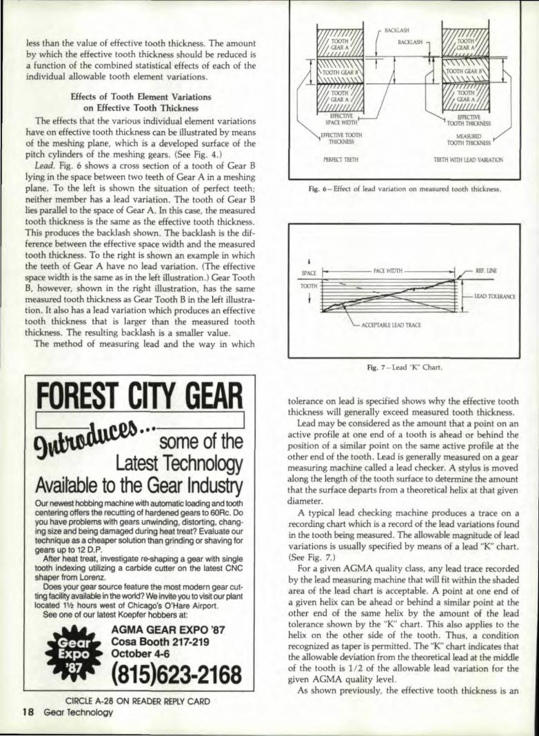
Lead. Fig. 6 shows a cross section of a tooth of Gear Blying in the space between two teeth of Gear A in a meshingplane. To the left is shown the situation of perfect teeth;neither member has a lead variation. The tooth 'of Gear Blies parallel to 'the space of Gear A. In this case, the measuredtooth thickness is the same as the effective tooth thickness.This produces the backlash shown. The backlash is the dif-ference between the effective space width and the measuredtooth thickness, To the right is shown an example in whichthe teeth of Gear A have no lead variation. (The effectivespace width is the same as in the left illustr.ation.) Gear ToothB, however, shown in the right illustration, has the samemeasured tooth thickness as Gear Tooth B in the left illustra-tion. It also hasalead variation which produces an effectivetooth thickness that is larger than the measured tooththickness. The resulting backlash is a smaller value.
The method of measuring lead and the way in which
FOIREST CIITY 'GIEAIRI I...'---------------~9 some of the'
Latest: TechnologyAvail table' to the, GeaJ IindustryOur newest hobbfng machine with automatic lloading and toothcenter:ing offers the recuttLng ,ofhardened gears to 6ORc. Doyou have problems with gears unwinding. distorting, chang-ing size and being damaged during heat treat? Evaluate ourtechnique as a cheaper solution than grindingl ,orshaving torgears up to 12 D.P'..
After heat treat, investigate re-shaping a gear with singletooth indexingl utilizing a carbide cutter- on -the latest CNCshaper from Lorenz.
Does your gear source feature the most modern 'gear cut-ting facilityavailable in the world?We Inviteyou to visitour plantlocated H"'2~ hourswest of Chicago,'s O'Hare' Airport.
See one of our latest Koepfer hobbers at
AGM_A GEAR IEXIPO' '8,7Cosa Booth 2117·2119Octo'ber 4-6
'(8,115.)6,23-21168GearExpo'87
CIRCIJE A-2S, ON READEiR RiEP,lY CARDI'8 Goor Technol'ogy
EFFECTIVE TOOTHTHICKNESS
PERfECT TEETH TEETH WITH I.IAO VARIATION
Fig. 6 - Effect of lead variation on measured tooth thickness.
Fig. '7- Lead "K" Char1.
tolerance on lead is specified shows why theeffeetive tooththickness will generaily exceed measured tooth thickness.
Lead may be considered as the amount that a point on anactive profile at one end of a tooth is ahead or behind. theposition of a similar point on the same active profile at theother end of the tooth. Lead is generally measured on a gearmeasuring machine called a lead checker. A stylus is movedalong the length of the tooth surface to determine the amountthat the surface departs from a theoretical helix.a.t that givendiameter .
A typical lead checking machi.ne produces a trace on arecording chart which is a record of the lead variations foundin the tooth being measured. The allowable magnitude of leadvariations is usually specified by means of a lead ''K'' chart.(See Fig. 7.)
For a given AGMA quality class, any lead trace recordedby the lead measuring machine that will fit within the shadedarea of the lead chart is acceptable. A point at one end ofa given helix can be aheador behind a similar point at theother end of the same helix by the amount of the leadtolerance shown by the "K" chart. This also applies to thehelix on the other side or the tooth. Thus, a conditionrecognized as taper is permitted. The "K" chart indicates thatthe allowable deviation from the theoretical lead at the middleof the tooth is 112 of the allowable lead variation for thegiven AGMA quality level.
As shown previously, the eHective tooth thickness is an

envelope value of tooth thickness. It is the maximum metalcondition for each specific gear. The measured tooththickness, as obtained by means of a measurement over wires,a chordal tooth measurement or a span measurement, is onlya local value .. It is a linear dimension between two similarpoints on a given tooth. These points represent only a verysmall part ,of the total surface of the tooth. Alsnthese pointsare evaluated near the mid-height of the tooth and usuallyat the middle of the length of the tooth. Each of the measur-ing methods involve only one or two of the tooth elementtolerances, lead, pitch, profile or runout, in variouscombinations.
Spacing. Fig. 8, left illustration, showsa. cross section oftwo teeth ofa perfect pair of gears in mesh in their meshingplane. The teeth are shown at the phase of the meshing cyclewhen there are two pair of teeth in contact. (See Fig. 2, topand midd1e illustrarions.) Fig. B, left illustration, shows theteeth of a perfect pair of gears in mesh. The right illustrationshows the effect of a spacing variation. When one tooth ofGear A is in contact with Gear B, the next tooth is displacedby the magnitude of the spacing variation, thus, increasingthe effective tooth thickness. Spacing (pitch) may be viewedas the amount that a given tooth is ahead or behind its COf-
rect position along its pitch rude relative to its adjacent tooth;thus, spacing variations over a group of teeth can becumulative.
P~ofile. Profile is generally measured by means of a pro-We checking machine. The machine traverses a stylus along
SSS CIIUlt:Chib,uilldisthel wide,st rang,e of'h!iglhlpower" 8Iult:omatic"I. tnn In,g, g;ealr'~_ype
I utehes.Ca..nabllilies:
5OOfI-Cl,lo 3,OOO.'OOOIt-ibtorqueo SpeOO'S Up' to 15,000 rpmo Foot and shaft mounted designsApplications:o PI1Ner stallonslor synchronous
condensing .o Naval shjp propulsion systemso DuaJ.driven fans, ,g.enerators.
compressors, pumps, etc.o Automatic tumin~1ge.ar ¥tE~mso Gas turbine stBnUlg applicatiOns
VIsIt our .Boothnl4 at tile AGMAGear EXpo '87.
#/ SSSCIU!C~~PBny_llllc.610West Basin RoadNew Castle, OEt9720 'USATelephone: (302) 322-8080Telex: '905003 SSS Clutch DelFax: (302),322-8548
CIRCLE A-320Nl READER REPLYCARD
SPAQNGVAlUATION
EffECTIVE TOOTHTHlClOOSS
mKTMSPACI\\1DTH
EFFECTIVE TOOTHTHJCKNE5S
EFFECTIVE SPACEWTImI
PWECTTEETH
Fig. 8 - Effect of spacing variation on measured tooth thickness.
""10- SPACE TOOTH_
-1!EF.UNI
'1---"-~--4 TO~
't1l'
DIAMETER
ACCEPT AIII.E'"1 PROFlU
TRACE
NI il I'j i!ORM
(]RaE
Fig. 9'-Profile "K" chart.
the active face of the tooth from root to 'tip. A chart is pro-duced which shows the departure of the actual profile froma theoretical involute profile for the tooth being evaluated.
The allowable magnitude of profile variation is usuallyspecified by means of profile "K" chart. (See Fig. 9.) For anygiven AGMA quality class, any profile trace 'that will fitwithin the shaded area. of the profile chart is acceptable. Thechart indicates thalt the allowable deviation from thetheoretical profile at mid-height is 112 ofthe allowable varia-tion for each quality level, For example, for agear ·of a sizeand AGMA quality number permitting a ,002' profiletolerance, the maximum metal condition could exceed the
september/OCtober 1987 19'

mid-height value by .001". In such a case, the effective tooththickness would exceed the measured tooth thickness by .001 •on each side of the tooth, a total of .002".
Runoui. Runout may be measured by placing a measur-ing wire in each successive tooth space as the gear is rotatedabout its axis under an indicator. A radial reading is takenat each position. Runout is the maximum variation from highto low readings of all of the tooth spaces in the gear. It isdue to an eccentric condition between the circle on whichthe teeth were cut and the axis of rotation, or due to an out-of-roundness of the gear .. Runout in a gear as "seen" by itsmating gear appears as variations in tooth thickness. Equa-tion 18 shows the relationship among space width, tooththickness and circular pitch on the standard pitch circle. Therelationship between radial measurement of out-or-roundnessvariation (runout), tl.C, and the tooth thickness variation isgiven in Equation 19.
Tooth Thickness Adjustment FactorIn order to determine the drawing specification value of
tooth thickness measurement for each of the measuringmethods, over wires, chordal tooth thickness or spanmeasurement, it is necessary to determine the value of tooththickness adjustment factor for the method to be specified.This value is subtracted from the calculated value of effec~tive tooth thickness to achievea value of measured tooththickness. The value of measured tooth thickness is then usedto calculate the specific drawing dimensions required by thechosen measuring technique.
DEBUR,RS GEARS.FAST1
SET-UPSTAKE
SECONDS* INTERNAL-EXTERNALSPUR & HEUCAl GEARS
TO 20' "NCHES DIAMETER11707 Mc8ean Drive, lEI Monte, CA 91732
(8181 442-.2898
CIRCLE A·l1 ON :READER REPLYCARD20 Gear Tec'hnology
The magnitude of the tooth thickness adjustment factor,.6.t, depends on the specific method of tooth thicknessmeasurement to be specified. In each of the tooth thicknessmeasuring methods there is a unique combination of toothelement variations that enter into the calculations, providinga stack-up of tolerances. Since i't is reasonable to assume thatthese tolerances will exhibit a normal. distribution, the rootmean square of an of the individual element tolerances thatenter into each specific measurement is used. This gives bet-ter than a. 95% assurance that the effective tooth thicknesswill not be exceeded.
Measurement Over A Single Wire.. The measured tooththickness o.f a gear is obtained most directly by a measure-ment over a single wire. This measurement provides thechordal distance between similar points on the profiles oneach side of a tooth space at a specific distance from the axisof rotation. A gear measuring wire, made to precise toleranceson roundness and diameter, is placed in a tooth space, anda radial measurement is made from the axis of rotation ofthe gear to the top of the wire. The wire typically contactsthe tooth at about mid-height. The quality variations thatenter into this measurement are lead (each side), profile (eachside) and runout. According to the profile '~K"chart. the tipor the root of a tooth can be plus metal by up to 112 of theprofile tolerance. This is also true of lead. It is also reasonableto assume that with two measurements taken at random, themid-point of runout will be measured.
Tooth Thickness Adjustment FactorLilt! [2 Wzvp)2 + 2(VZVL? + l/,vTRz + vs2]'11
where
VIR - 2 tan cP VR
The measured tooth thickness, T MI, on which the drawingvalues of measurement over one pin are based, may becalculated as follows:
TMI - TE - Liltl
The value of measured tooth thickness is used to calculatethe specified measurement over one wire. (See Equation 12.)
Gear Tooth Vernier Measurement. The gear tooth verniercaliper measures the normalchordal distance between theprofiles of a tooth at a specified distance from the top land(outside diameter) of the tooth. A gear tooth vernier is a typeor vernier caliper which includes a special blade that can bepile-set to a drawing value or chordal. addendum to establishthe distance from the top land to the point on the teeth wherethe measurement is to be taken. Equation 13 may be usedto calculate the chordal addendum setting. The distance be-tween the jaws is read as they make contact with the sidesof the tooth ..This is the chordal tooth thickness. This valuecan be converted to measured arc tooth thickness by Equa-tion 14. Contact between the sides of the tooth and the jawsof the tooth vernier caliper occurs over a relatively small areaof the tooth in most cases. Thus, the measurement does notinclude either the profile or the lead variations. Since onlya single tooth is evaluated at one measurement, spacing isnot included. Also, the diameter at which the jaws contactthe tooth is fixed by the outside diameter, which is usuallymachined independently of the teeth; thus.the ruJil effect of

;
Home Of The
Cincinnati liearcompanyFinest Quality Gears Since tson5657 Wooster PikeCincinnati, Ohio 45227(513) 271~nOO
SEE US IN BOOTH #418
~A-~_~PLY CARD~ ""-
~ ------------------------------

High Iintensity,Mult;il·,Frequency ScannersIRiEO:U,CEIHIEAT TIREATINGC'OSTS up to 4010/0A recant TOCCO development, Hi.gh IntensityIinduction Hardeningl (HII:H)TM,:reduoes heattrealing costs substantiaJlly, in a va~iety of applli-cations. HIIH has been used successtully withapplications on automotive and off-highwayengline' and drive train components.as weillasspecialiized gear appliications. The ~jIJ!IHscan-ningl process, with pr,esenUechnolog¥.canbe a.dapted to parts up,to 1S," diameter andI'engths to 120".Parts that previously were name hardened in abatch process, can now be mduction -hardened,in-line, with grea.terflexibillity, more preceion,individual quality monitorinq, and at lower cost,High Intensity "nduction Hardening is indeed,a process IO~"The Future,".
'Cross secMnof camshaft Ilobe demonstrates uniformity 'Ofhardening.Multi-frequency, high intensity hardening 0" gears produces a highhardness characteristic lor improved surface cont.acllaUgue life.High residuall compressive stress in the root area is also achievedlor improved loolhstrength.
,Forthe' latest state-of-the-art heat treari_ng technology,contact your TOCCO r~presentative. or calJ:TOOCO.Inc., 30100 Stephenson Highway,. Madison Hts .• M/~48077..Phone: 313-399'-8601 or 1-800-468-4932(outsIde Michigan).
A unit of.Psrk Ohio Industries,. Inc.CIRCIJE A-37 ON READER REPLY CARD

runout may be present.
Tooth Thickness Adjustment Factor
tHe - [2(%vp)2 + 2(!hvl)2 + 1/tVTR2 + v/]"
The measured tooth thickness, TMe, on which the draw-ing values of chordal tooth thickness measurement are based,may be calculated:
TMc - TE - .:l.t.:
The vernier caliper setting for chordal tooth thickness maybe obtained from Equation 14.
Measur;ement Over Two Wires. In this technique, a gearmeasuring wire is placed in each or two tooth spaces nearor at opposite ends of a diameter, and a measurement madeacross the tops of the wires. The wire diameters are chosensuch that the wires will contact the tooth surfaces near theirmid-height. Contact conditions are similar to the over onewire measurement, except that the measurement is not relatedto the gear axis.
Tooth Thickness Adjustment Factor
At2, - [2(11zvp)2 + 2(112VL)2 + vs2 +VTR2Jv1
The measured tooth thickness. TM2, on which drawingvalues of measurement over two pins are based, may becalculated from:
TM2 - TE - .:l.t2
The value of measured tooth thickness is used to calculatethe specified measurement over two wires. (See Equations15 or 16.)
Span Measur;ement. In this technique, a measurement ismade over a group (span or block) of teeth using a conven-tiona] vernier (dial) caliper. The number of teeth includedwithin the span will determine where the contact will takeplace on the teeth. In most cases, a number of teeth to beincluded in the span is, selected which will provide contactnear the mid-height of the teeth. lnaddiHon to the effectsof proHl.!! and lead on the sides of two teeth, there is the ef-fect of the pitch accumulation produced by the number ofteeth within the span. The full effect of spacing is includedin the measurement.
Tooth Thickness Adjustment Factor
.:l.'ts - [2(VzVp}2 + 2W~vLl2 + VrR2jY'
The measured tooth thickness, T MS, on which the draw-ing values of span measurement are based may becalculatedas follows:
Appendix AGeneral Eq~aHons for Tooth Thickness
(Pa:r.alM Shaft Gearing)'Standard Center Distance
C - (Np + NG) I (2 P d)
Standard Pitch Diametero -N/Pd
(1)
(2)
Operating Pressure Angle<to - COS-l(C cos<Ji/C')
Transverse Diametral PitchPd - Pnd cos't
Pitch Diameter of Master Gear
DM - NM/Pd
Operating Pressure Angle(On a Ge.ar Rolling Fixture)
<to = C05-1 (C cos41/CM)
Tooth Thickness of Work Gear
(3)
(4)
(5)
(6)
(From a Gear Rolling Fixture Measurernent]T w - ((jnv<;ll" - inv4l) (OM (N + NM) + ?l'DM) I NMI - TM
(7)Operating Pressure Angle(Gear Rolling Fixture)
<;ll" - inv " inv4l + [NM(TM + Tw) - TD'Ml I[DM(NM + N))
Testing Center Distance Specification(From Value of Punctional Tooth Thickness)
MM - C cos* I cos4l" (9)
Pressure Angle To Center of Wire(Measurement over 1wire)
*2 - inv-1 [(TM1/Dw) + mvel> + (dw/~) -(TN)](lO)
Radius to Center of WireRw = Obi COs<;ll2 (11)
(continued on page 36)
On Mitts, & MerrUl keyseaters
INO TOOLIII GWORKS BETTER.
It's a lad:Mills & Merrill keyseatersperform belt r with genu ineMitts & Merrill 'tooling. Youcut keyways Slfaighter.faster. With more accu racy.And cullers stay sharplooger.Best of all. Mitts &Merrill tooli ogcosts no
mer ... usually less. Soyou cut costs while u cuikeyways.P.rolecl your keyseaterinvestment-insist ongenuine MitIs & Memlltooling.
1.11_ft'-. __
'till""I!! lbullll!!lli!!! bI!!!uSIII!I1QrEm,t!:IIIL __ "
Mitts, & IMerrill! Key.seatersICIIft'III -- [lillOOIJlill ~
CIRCtE A-17 ON READER REPLYCARDSeptember/OCtober]9S,7 23

Selection of' a Proper Ball Size to Check anInvolute Spur or Helical Cear Tooth
Carroll K. ReeceHarlan Van Gerpen
Van Gerpen Reece EngineeringCedar Falls, Iowa
Abstract:The selection of a properly sized ball or pin to use in the check
of dimension over or between balls or pins is not an easy task. Ifthe ball size is taken from standard tables of Van Keuren Pins forstandard pitches, and if the proportion of the tooth being checkedis not standard, interference with some feature of the gear tooth mayresult, giving an erroneous reading for the tooth thickness. Thisar-tide gives a procedure for selecting a properly sized ball or pin tocheck an involute tooth of any proportion. A set o.f standard sizesfor both inch and metric balls or pins is suggested.
IntroductionA much-used method for checking the tooth thickness of
an involute gear tooth is to measure the dimension over twoballs placed in most nearly opposite spaces in the case of ex-ternalgears, and the dimension between the balls in the caseof internal gears. This measurement is then checked againsta pre-calculated dimension to denote an acceptable part.
From this point, references will be to external gears only,It is confusing if the text is correct for both external and in-ternal gears because the words "over"and "between" are con-tinually interchanged when addressing the dimension overor between balls. Confusing, also. are references to majordiameter of the external and to minor diameter of the inter-nal, and to the the root of the external and the major circleof the internal.
However, calculations for external and internal gears arethe same if a minus one factor is entered at certain pointsin the equations for internal gears. The formulas shown willproperly calculate either external or internal gears and splines.
The dimension over balls is a measure of the thickness ofa theoretically true involute tooth generated from the basecircle used in the equations at the ball contact point. The ballcontact point is the point on the tooth where the statedmeasuring ball contacts the tooth on both sides of the toothspace. For standard gears the size of the measuring ball is
24 Geor Technology
usually chosen so the ball contact point is near the gear pitchcircle.
Tables of sizes over balls have been published for standardgears using standard increments based on constants for ex-ternal gears and internal gears, the ball sizes being determin-ed by dividing the constant by the diametral pitch of the gearset. These ball sizes are satisfactory for purely standard gears.But for gears with teeth which are of non-standard propor-tions, the pitch circle is sometimes not near the middle of thetooth height and is sometimes off the tip of the gear toothor below the gear tooth root. In the case of non-standardgears, a measuring ball size which contacts the gear toothsomewhere near the midpoint between the form circle andthe outside circle must be chosen.
Exact 8aU SizeThe exact measuring ball size needed to contact this point
is calculated by using Equations (2), (3) and (4). -The size of the measuring ball determined by Equation (4)
would be different for every gear tooth designed withnonstandard proportions and if allowed to stand, wouJdcreate a difficult, if not unmanageable, system of measure-ment. Keeping the ball contact point at the mid-height of thetooth is not a critical factor so long as the ball contacts theinvolute surface, and the problem has been resolved bychanging the measuring ball size as determined by Equation(4) to a size found in a predetermined standard set of measur-ing ball sizes.
Standard Ball SizesAny set of standard ball sizes may be used to determine
the final. ball size. The size increments must be small enoughso that the ball contact point does not move too far radiallyon the gear tooth when the ball size is changed from the ex-act size determined by Equation (4) to one of the standardincrements. Experience has shown that results will besomewhat better if the exact ball size is changed to the nexthigher standard ball increment, thereby moving the ball con-
CINCINNATI. OHIO
OCTOBER HI 1987BOOtH ,434-436
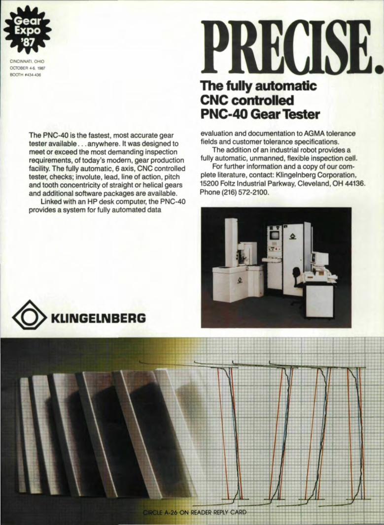
Tlhe' PNC~40 is the tastest, most accurate geartester ,evail'eDle'.... 8_nywher,e.It was designed tomeet or e~ceedl the, most demanding inspectionrequirements, ,of today's modern, g,ga,1'productionfaciUty. The fully aut.omatic, 6 axis,iCNC ,controUedtester; ,checks: lnvolute, Ilead, Une of action, pitchand tooth 'concentricity of .str.aight or helical gearsand ,additional software packages are availlable ..
Unk;edlwith an HP desk computer, the IPNC·40provi'des a system for fully ,automaledl,clata
~ KUNGELNBERG
n. ,fUlly autom ..i:cCN'C: controll ···1PNC-40 'Gea-,Tester'evaluation and documentation to AGMA tolerancefields and customer tolerance specifications.
Theacldition of an industrial robet provides afully automatic, unmanned, fJexibl'e inspectionl cell.
For further information and a oopy of our com-plete,litersture" contact: IKJinge'llnbe:rgCorporation,15200 Foltz Industrial Parkway, Cleve'land, OHI44136,.Phone (211,6) 572-2100.

tact point toward the gear outside circle. However, roundingto. the nearest standard size or moving to the next larger orthe next smaller size is a matter of choice. Any method willyield satisfactory results if the proper checks are made forinterferences with important teeth features.
Experience has also shewn that within the ran~e of ballsnormally used for measuring gears, a 1/64 - increment ferthe sizes of balls is satisfactory and actually gives more selec-tions than are needed, Since the balls are net outrageouslyexpensive, this selection is satisfactory for inch sizes.
The R40 series frorn ISO recommendation R-3 has beenselected as the standard set of metric pins fer measuring ISO4156 and ANSI 892-1980 standard metric splines. A goodfeature of this selection of sizes is that the size increment in-creases as the sizeof the pin (ball) increases. The R40 seriesgives very satisfactory results fer metric ball sizes for measur-ing gears.
InterferenceWhen a standard size ball is substituted for an exact ball
size, the contact point moves from the exact mid-point ofthe tooth. This change must not cause the ball to interfere
AUTHORS:
HARLAN VAN CE~ 1!aS28 years of experience at the fohnDeere Product Engineering Center in Waterloo. iowa. where lie sensedas mannger of technical seroices and a principal engirJeenng specialist.He is a licensed professional engineer in the Stale of Iowa and Ii
member of the ASAE where he is Ii member of the Research Com-mittee ana the Instrumentation (md Controls Committee. He is alsoa member of the SAE Education and Human Factors Committees.Mr. Van Gerpen holds a master's degree ill electrical engineering fromthe U'liversity of Illinois.
CARROll. K. REECE worked for the John Deere Product Engineer-ing Center, Waterloo. Iowa, as an engineering design analyst andsupervisor in the mechanical elements deparhnent. He has served for25 years on the AN51-B92 National Spline Standards Committee andfor 18 years on both the ISO TC 32 international Spline StandardsCommittee and the ANSI-B6 Natiol1Cl.iGear Standards Committee.He holds a master's .degree in' agricultural engineerirlg [rotn KansasState University Rnd is a licensed professional engineer in the Stateof Iowa.
with any feature of the gear tooth ..To insure this, calculatethe radius to the standard ball contact point, the radius overthe balls and the radius under the balls.
The following features of the gear 'tooth must be checked.The root surface of the tooth. To. get a good measurementof the gear tooth thickness, the ball must rest on the involuteteeth side surfaces. It is very difficult to tell in some cases,whether the ball is resting on the root surface or the involutesides of the tooth when measuring a gear. It is much betterto check this by calculation when determini.ng the dimensionover balls so as not to leave this responsibility to the shoppersonnel when the gear is being cut. The check here is tocompare the radius under the balls with the gear root radius.If interference occurs, the ball size must be moved to. the nexthigher standard increment and the calculations for in-terference repeated,
The ball contact point must not be below the gear involuteform point. Equations (5), (6) and (7) assume that. the involuteform extends from an infinitely large diameter to the basecircle: whereas, it actually only extends from the tenth tipto the ferm point. Therefore, a separate check must be madeto. be sure the ball contact point is net below the form point,Again, if this interference occurs, the solution is to move theball size to. the next higherincrement.
The ball contact point also must not be outside the gearoutside circle: otherwise 'the ball will rest on the comers ofthe teeth at the gear outside circle. This wiU result in an er-roneous reading. If the balls are found to be resting on 'thecomers of the teeth, change the ball size to. the next lower'Standard increment and repeat the checks for mterference.
The radius over the balls should not be less than the gearoutside circle radius because' the anvils of the measuringmicrometer may rest on the corners of the gear teeth. Thisproblem is solved by increasing the ball size to the next higherincrement.
A situation can occur where the ball size is being movedup and down in an effort to avoid an interference only tohave interference occur at some other point. When that hap-pens, the ball size should be moved back to the original ex-act size found by Equation (1). If that ball isresting on theroot surface, a calculation is made to determine hew much
(Continued OM page 31)
26 Gear TechnolOgyCIRCLE A-22 ON READER REPLYCARD

From conceptto COM LETIO
StarCut can helpwith every phaseof Gear Manufacturing
'We provide' the best of American and EuropeanMchnology and equipment to fill the productionneeds of American gear Manufacturers.
o Determine the best processand provide the machine toolsto do the job.
--, Engineer and furnish thecorrect cutting tools, clampingtools and work systems.Provide the necessary gearinspection equipment andmachines.Supply cutting tool sharpeningmachines.
- Install the machine tools andequipment.
o Train operators and mainte-nance personnel.
I Provide continuing backupand support.
/IlJiijj927~ARCUT SALES,INC.

From conceptto COMPLETGear Manufa.cturers have access to the following
~~, .MachineJIIII ")';0'0'1'5Standardl and CNC Hob SharpenersShaper Cutter SharpenereNC 5-Axis Tooll GrinderCNC 6-Axis Too:1GrinderMaster Gears
Hobs1F0rm·R,elievedMililingl CuttersGunl DrillsIPressure-Coolant ReamersKeyseat CuttersiP'olycrystalliine Diamond Tools
Mechanically activated precisionclampingl tools .
LORENZShaper CuttersSpur Gear Sharpening Ma.chineShaper Cutter Sharpening Angl!e
MeasurilOQllnstrument

StarCut reSQ,urces ...
Ma.,chine ToolsGear Hobbing Machines
Cuttiing Tools,Hobsfor Fine Pitch GearsThread MiUingl CuttersPwWe Cutter:sfor Sevel GearsShaping Tools
IIUCNC Gear Shavi1ngl Mach,ineseNC Gear IRoliing MachinesGear Testing MachinesShaving Cutter Grindling MachineseNC Gear Tooth Chamfering
IM'achiinesGear Deburrilngl MachinesCNC Hard Gear Flini,shing Machines
Planni1ngl andlEngineeringFlexlible Machining Systems

Froml co,nc,ept10 CO, _'P'LII'ION continued
GOLD STAR TiN COATIN'GSFor cutting: tools and wear parts.
We offer a wide range of talent,resources and expertise to inemetalworking industry and togear manufacturers in particular.The specialized machine toolsand qua'lity cutting tools of ourown manufacture, as well asthe products of the Europeanfirms we represent in America,are specifically chosen forsuperior gear production.
Ongoing: research, experimen-tation, and testing programs atour various manufacturing: facili-ties and labs ensure StarCutcustomers access to the latest
I
TiN COATING SYSTEIMISComplete turnkey applications.
technology. From hardware tosoftware to customer service,we strive to bring excellence togear manufacturing and tometalwork.ing, in general.
Star products and those of ourEuropean affiliates are rnarseteothroughout North America. Wemarket Star products worldwide.OUf dtract salesmen and repre-sentatives work with customersthroughout our marketlnq areasand product specialists service allStarCut su pplied mach ine tools,cutting: tools and equipment.
We offer TiN coating service at
one of our facilities and designand install complete Ti N coatingsystems for customers needlingtheir own facilities.
Tlhrough PLANHrNG USA, INC.we offer expert help in planning:new products and creating; newi,ndustr,ial facilities. We handleanything from simple manufac-turing cells to complete turnkeyoperations.
From Concept to Completion,StarCut can help with everyphase ot gear manufacturing;in particular and 9,enerally inalmost all rnetalcuttino activity.
//lAir'"., /.l'jARCUT SALES,INC.&/ ')~3461 Industrial Park IDrlve
IFarmington HiUs,lMl 48024313/474-8200 Telex 230-411
CIRCLE A·S 'ON READER REPLY CARD

fig. l! -In :seletti!!g the measuring ball size for a full depth gear 'tooth, thenext standard increment larger than the ,exa.ct size is, usually satisfactory.
the ball must be flattened to dear the root surface. fromEquatton (2) it ean be noted that the 'exact ban size contactpoint wiUnot be below the form point, nor will it be outsidethe gear outside circle, but the ball may be resting on the gearroot surface. Even a standard ball may contact the root ofthe tooth. This condition must always be checked, whetherusing a standard ball or an exact ball size,
Fig. 1 illustrates the process of selecting the ban size formeasuring a full depth gear. The dashed lines are the exactball size as determined by Equation (4). Point A is the ballcontact point for this ball and is chosen midway between theoutside circle and the form circle by Equation (2). The solidlines represent the standard ball, and Point B is the ball con-tact point for the standard ball. Note that the standard balldears the root of the gear tooth, and the radius over the ball
Ifi IPIEREZ MAC,HllNiETOOl, CO.I :T11 ,Ginger 'Court • East Amhel'St
New York 140511• (716) 688-6982Okamoto Model HTG~.24
High-Tach .£='ormGear GrfnderDesigned, BuilIand Sold by the GroL(p
That Can Solve Your Gear Grinding Problems
This Gear Grinder has been Designed to Meetthe Requi~emel1ts of an Gear Manufacturers
Whether Job Shop or !High ProductionFOI" cr~ sed or 'conventional spur geaJ' grinding
'Onlema/ and external) withluil ... axis CNG control.
.,. . ~a!!on.' ',.Ma)<. OUtSide dJ~ .•. , •.••.... 24f1111n.roo! oJamelm" .••• .... . .. .. • 31~·IiiIIn /Mill! OJ'. .. .. . . 32 ID 2Max. numller 01 'iBed1' .. .. . • .. . eooM:.JJL ".urrber 01'[_"' ...........................•
Someof the 'dlUra Include:al no restrlctiO!1sto Crowninglcapability - any crown 'is possibleb) no cams are :requlredllor ,!!fI)' functiOnc) lllVOlule control In increments of .00004 to any desired involu1a tip or flank, modification
d) choice of three diff'erent. inlernal heads
I
e) ""' or,,',e: xtemalBar, azon wl'leelc:apabllilyGEA'RI EXPO ~B7 - BOOTH'508
Also in aII.BndB:l1lCe' - NiCk TiD.III'-O.kamoto CorporlionRoo MidiIII' - Universal Gil'
Com.puter Programs for the 'Gear Mfgr.
CIRCLE A-29 'ONI READER R.£P,lY CARD
Fig. 2 -In t his example, the Hrst standard increment larger titan the ,exact,ball contacts outside the outside circle limit; the next size small r contactthe root circle. The ball must be flattened to get a good me urement. Thishappens with stub tooth gears with low pressure angle.
is outside the outsidecircle of the gear. This ball would besatisfactory to check this gear. Finally, the dimension overthe balls is calculated from Equation (10) or (11).
It can become a burdensome task to make the calculationsoutlined here only to discover interference at some point andhave to do everything over again. The occurranee is unlikelyin the case of full depth gears at the most often used pr-essureangles, but choosing a satisfactory standard ball size for gearsand splines of unusual proportions can be a difficult task.Fig. 2 illustrates the type of gear or spline tooth which mightpose a pr-oblem. The involate in Fig. 2 is very short. When
2331 Lemoine
New Intech P.ower-Core ™com pas l,t,egears. out-pertorrn,other availlable, gears wherenoise, wear, chemicals, vibra-tion. moisture and alIgnment,pro'blems exist.
I
A Unlq.u,'B,:, a,om, 'blnatlon oflduramLd securely castaround 8 metall hub opensnew alternatives for 'problem
, solutions and high torqueap·'pJilc.allons (e.g. worm Q,ears,spiral bevel (fears, eIC~)'.
Greater R.O.I. ,savings arerealized lin lower ,r,eplacementmachlnlngl and, maintenancedown·tlme, eests,Find out how Power·Coregears, can Ihelp'you. 'Call orwr,Jt,et,odayfor 81lest samplefor your gear app'llcatlon.
CIRCLEA~34 ON IREAIOER'IRBPlV CARDSept,ember /'Octol:)er 1987 3,1

Q. Wouild yOlu beneve that thissleering gear pinion could becol'dformed?
i
'i A. Beliieve it IHe'UcremenlalESCOFID.rnachines can do it-and up t'olive Urnes faster thaln,any'other method!
Cold forming: precise helical configurations such as shaft steering gearpinions can only be done using ESCOFmR Helicremental macllinery.Other benefits: chfpless, machining • improved mechanical properties'. no waste. exceptional surface Quality • exact tolerances .' lessdowntime .' lower unit cost. ,exceptional increased productivity. Call orwrite for information on how ESCOPlERrotary cold forming techniquescan save time and money in your operation.
ISCOFIER, INC.A YAll:OUREC GROUPCQMPAH'!'
Leadership in rotary cold forming technology
10 Ann sr, P.o.. Box 379, Oakmont, PA 15139- (412)826·8588Telex: 264107 ESGO UR • Telefax: 412.826 8560.
CIRCLE A·13 ON READER REPLYCARD
the ball size is changed from the exact size represented bythe dashed lines at Point A, the contact point moves off thetips of the teeth at Point B. The ball size is moved to the nextlower standard increment, which is below the exact size. Thecontact Point C is below the center of the tooth, but is inthe satisfactory range.
Sometimes when the involute surface is very short, PointB is outside the outside circle, and Point C is below the formpoint. In this case, the exact ball size is used. In Fig, 2 thestandard ball at Point C contacts the mot of the gear so a.flattened dimension is calculated.
A computer program can be written which can accomplishthis task very quickly and make all the checks necessary toguarantee good results.
One might question why a gear or spline tooth like theone shown in Fig. 2 would ever be designed, but thetask of the computer program is not to decide what isreasonable. So long as the input data is valid, thecomputer program should determine a proper hallsize and the dimension over those balls.
Fig. 3,- This photograph shows an actual master gearwhich has proportions similar to those shown in Fig. 2.The method outlined chose a measuring ball size withoutdifficulty .
.32 Gear Technology
GEAR D'EBIURRINIGGrinding .• Il:Jl1ushing.•.MUlling
Single & Multiple StationEliminate Tedious Hand DeburringA Modest Iinvestment With A Fast IReturn,
S:EE US AT iBOOi)"IH#202.211 East 18 Stl'eet, NY.C, NY: 10003,212-475~OO82 Telex: 499'7976
CIRCLE A·23 ON READER REPLY CARD
Fig. 3 shows a real. master gear for which the data waspresented to a computer program written according 'to thesystem outlined above for choice of a measuring ball. Theprogram picked a standard inch ball and calculated a check-ing dimension over bans without djfficulty.
SummaryFollowing is a summary of the steps to follow in picking

FOR ASTEREASY TO IINSTAL.L - Because of its smallsize and weight, the FORMA'STER. does, no •. reoqu,i!re major machine modifications and can be Installed on nearil,y any grinder. tnstauatten canIUsuaUy loe,accompllshed In less than a day.
EAS,Y T'OI OPE'RA:TE. - T'woa)<is design slmpllftes programming and eperatlen. You canchoose between four popular controls that teatur'e' menu and G·Gode p'fogr,ammlng" grap'hicslmutatlen, automatic corner r,o'Undlng, automatic diamond thlekness ccmpsnaaucn, andmore.
MADE, !liNIU.S..A.
Patent No. 4,5591,91'9
IIMPROVES A.CCURACY
--..
.-
V,ISI,T US ATBOOTIHI¥334~336'.
R,iEDUCES W,HEELDR.ESS'ING TIME
A'CCURATE - To within:!: .0001" of pr,ogrammed dimension, with repeat accuracy to within.00006 ". IExtra preclslon Ironer bearing ways, pre-loaded rolter screws and' optical IIllnearencoders, as w,ellas superior desllgnand construction, ,g,livethe FOAMASTER tihe aloillty~.o. h,o.ldinspection gage' acculra,cy.PR,O,DUC;TIIIVE - No.,templates or spec.la'l dlamo.nd mils are needed, so Illeadtlrnes and tcol-Ing Inventories are reduced: Most forms can be prcqrsmmed and, dressed In, ready to. glrind in30 to 45,minutes. Refr,es'hln'QIthe form between ,glriindling passes Is acccrnpllsned In seconds ..
VIERSATIILIE - Gan be used wU.h slng,'lle petnt diamonds or with cpttonal rotary dllamondwheel aUachment. Nearly any form can be oressec quickly, ,easily and aeeurataly,DUR_ABLE. - Hard seals are closely flUed and! are air purgled to. totallly exclude eo.ntamina.·tlen, Sealed servo' meters, auternetro II,ubrlcaUo.nand to,tailly enclosed 'encoders mlnlmlze downtime and ensure long service life.
P'.O.IBox 69.Arden, NIC:28,704·(704) 1684·1002.
P.o,. IBo.x 207Niorthville" Mil 4816,7
(3,113)349·2644
CIRCtJ A-19 ON READER REPLY C.ARD

a measuring ball size and finding the dimension over balls,
1. find the normal base tooth thickness from Equation (1).
2. Find the midpoint of the tooth between the form pointand the outside circle from Equation (2).
3. Calculate an exact ball size to contact this point fromEquation (3) and (4).
4. Change the ball size from the exact size to a standardsize either larger or smaller.
5. Check for interferences with important features of thegear tooth using Equation (5). (6):, (7), (8) and (9).
6. Move the ball size in the appropriate direction if thereare interferences. Repeat the checks.
7. Change the ball size back to the exact ball size and checkfor interferences if a satisfactory standard ball cannotbe found. Calculate the flattened size if the ball con-tacts the root.
8. Finally, calculate the dimension over balls using Equa-tion (10) or (Ill'.
EquationsBTN is the normal. tooth thickness at the base circle. If the
tooth thickness is given at any other point on the tooth, BTNmust be found. Use Equation (1).
BTN = BD-Cos (BHA)" (ITDD + (I)(Cos (HADD)*DD)
K*lnv(Acos (BD/DD)))
Equation (2), (3) and (4) are for choosing the exact ball size.
PACP = Acos {(Z"BD)(OD + FD))
(2)
K*lnv(p ACP) J + PACP
D = K*((]nv (PACB) + K"~)Z
*Cos (BHA)*BO - K*BTN)
(4)
After the standard ban size has been selected use Equations(5), (6), (7), (8) and (9) to determine if the standard ball sizeis satisfactory.
PACB = Ainv[ K·(BTN + OS) - K·~) ](Cos (BHA)*BD) Z
RCB = -=B;..=:O'----==_:_2-Cos (PACH)
(5)
(6)
RCP = .J !(RCB*Sin (PACB)) _ K*OS J2 + (HD)2L 2*(05 (BHA) 2(7)
(8)ROB = RCB + DS2
RUB = RCB - OS2
(9)
When the final selection of ball size is satisfactory, use Equa-tion (10) or (11) to find the dimension over balls, dependingon whether the number of teeth is even or odd.
HZ is odd:
OBALL - Z .. RCB • Cos(90/ Z) + K .. OS (10)
(continued on page 47)
TRUE DIME:NSI'O'N GE:AR INSPECTION- ------ .- - -
•.
-
Provides actual overball/pin measure-
ment af.anyhelical or
spur gear orspline with-
out the need.ofcostly
setting masters,
Provides vitalS.P.C. information .
Gage Division
ailedCAP:ACITY:
'9" O.D.8" I.D.Booth 435,
851 OHIO PIKE- 'CINCINN'AJI, 0111101 45245 - ,(5113) 752.1600II___ ....,; ---'=C:::IRC!!·~~=U!!:::.--:.!:.A~-3"".'~O~='~ONR~DERREPLY CARD

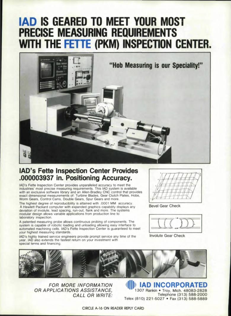
"Ho'b Measuring is our Speciality!"
lAD's F,ette' Ins,pection Center' Plr,oviides.000003,9'37 lin" -PosiUoningl Accuracy,.lAD's Fette Inspection Center provides unparalleled accuracy 1,0meet theindustries' most precise measuring requirements, This lAD system is availablewith an exclusive software library and an Allen-Bradley CNC control that providesexact dlmenelonal measurements of: Turbine 8lades. Gear Clutch Plates. Hobs,Worm Gears, Control Cams, Double' Gears, Spur Gears, and more,The' Ihlghest degree of reproducibiHly is attained with .0001 MM ac-curacy,A Hewlett Packard computer with, expandec graphiCS capability displays any Bevell Gear Checkdeviation of involute, lead spacing, run-out, flank and more, The systemsmodular design allows variab'leapplications from production line 10
laboratory inspection. II = IA patented! measuring probeaUows continuous probing of components, The ~. r{' (~>.- ):45
,\
system is capable 01 robotic loading and unloading allowing easy interface to .~1=1"automated machining, cells, lAD's Fette Inspection Center is guaranteed to meet " ='. ~.. ,your highest measuring standards. .-lAO's highly trained service engineers provide prompt service any time oflhe lnvoluteSear Checkyear. lAD also extends the fastest return on your investment withspecial terms and f,inanclng.
FOR MORE INFORMA TIONDR APPLICATIONS ASSISTANCE,
CALL OR WRIT.E:
1,1111111 I~D ~NCOR.PORATE,D- 1307 IRa_nkJn• Troy. Mich_ 48083-2828
Telephone (313), 588-2000Telex ,(8110) 2211-5027 • Fax (31'3) 588-5889
CIRCLE A-16 ON READER ,REPLYCARD

Effects, of Hob Quality and ResharpeningErrors on Generatmg Accuracy
Brian w. OuHAmerican Pfauter LimitedIlk Grove Village, Illinois
FI '~UI\O\UI" - IPllel'lYOJloflonIR 1!'!oIIIeIF;IJ= Ileodftl = ioolMo-looth oomposHeIAI - Total composlte
IIOUIICE 't:e:lWAIISQNS: DiN 3962' (~07.) and .AGMA 30000NOll; SH' lHf ICI\W sr~ I'()I;I ElW:I~
Fig. 1- Adlieva'b!e accuracies by machining method,
IntroductionThe modern day requirement for
precision finished hobbed gears, coupledwith the high accuracy characteristics ofmodern CNC hob bing machines, d •mands high toolaccur cy.
Modern CNC hobbing machines arecapable of pr.oducing gears with lead andpitchaccuracies of AGMA 14-15, but arestiUlimited by the manufactured accur-acy of the hob 'to a lower quality levelon the involute profile (Fig. 1). For highaccuracy hobbed profiles, high accuracyhobsare necessary.
The geometric peculiarities of the in,·volute worm, from which the hob lderived, must be dearly understood toavoid loss of hob bed accur,acy. Pur-chased tool accuracy and tool resharpen-ing maintenance bear SO'Utinyin, orderto preserve hobbed a curacy.
GeometricalP' culiarities of Hob
A hob is derived from the involutehelicoid worm. A hob i a rotating eut-
AlffHOR:
BRIAN W. CLUFF is safes mRnager ofAmerican Pjcllder Ltd. He has been' involvedwith geRf manufRcturing and measuringmachinery since 1963, He is t':I/~author of over25 technica! papers on gear manufacturing andmeasun'ng Rnd ,is the aut.horleditor of GearProcess DW!Qmics, He is II' frequent speakerat the AGMA Gear Symposium and ,the SMfGear Manutadun'ng {:, Processing Clinic, Heis a member of SMf ,and ASME and an ac-tive member of several AGMA committees.Mr. Cluff isa gradJJateof Washington tend inUniversity. Lexington, VA
September/'October 1987 31

In_ ........"''''11'_ ----orH'StrL.g:H11.l1OM1
__ 01 ........._'_01',_-I,SlOtt ",,'_ifiut_ ---'-I1bprQiifICM,'liR',itI,,*,) ....--.....j...--'
N~HCt!Onol__ ,,,01Il00
Fig. ,2-Geomelrical elements of a typical cylindrical hob.
Forest City Gear features the most modern gear cutting facilityavailable to you in the wond, We speciallize in hobbing andsl1api'ng ultra precision g,ears in low. medium and high volume.We aliso offer crown hobbing on the latest auto-loadingI'lobbing machines. "
Tile next time you need precision gears, come to The Source.Forest City Gear. 11715 Main St." P.O.,Box 80, Roscoe, IL 61073.(815)1623-21168 IFAX: (815) 623-8620
CIRCLE A-27 ON REA'DER REPLY CARD38 Gear Technology
ting tool with its cutting edges arrangedalong a helix. It is used for generatinggear teeth or other forms in a cylindricalworkpiece (Fig. 2).
A hob is a reducing cylinder. Over itsusable lifetime its diameter gets smallerdue to repeated sharpenings. Each timeit is resharpened it changes size relativeto the amount of outside (tip) clearanceand flank clearance (cam or backoff).
Every hob is designed with a. basic(generating) rack profile which defitnesthe pressure angle, the addendum anddedendum, the fillet radius, designmodifications of the addendum profile,and design modifications for preshave,pregrind, preroll and prehard finish.
The Natureof the Enveloping Cut
Deviations from the theoretical ordesign generating helix of the hob (Pigs.3 and 4) effect the polygonal pat.h oEtheenveloping cut along thegea.r toothprofile.
Figs. 3 and 4 show a single thread hob.In one revolution of the hob each of theU cutting edges removes meta] from thetooth space enveloping the profile. Theprofile is made up of a series ofindivid-ual cuts. The more cutting edges in ahob, the tiner the network of envelop-ingcuts, The fewer the number of cut-ting edges in the hob, the rougher the in-volute profile.
If the hob is manufactured with devia-tions along its generating helix (threaderror) or is resharpened so as to displaceone or more cutting edges from the nom-inal pitch line cylinder of hob, the effectis a deviation in the network of envelop-ing cuts. This deviation manifests itselfas pr-ofile error (Fig. 5).
Incorrect resharpening of the hob pro-duces deviations in the design geometrywhich ·effecl the basic rack tooth form ofthe hob, the positlon of one cutting edgeto another, the rake of the hob cuttingedge, and the lead of the gash (whetherstraight or spiral), These deviations arereproduced in varying magnitudes on theinvolute profile of the gear.
Mounting a theoretically perfect hobon an ,eccentrical1y running a"rbor 'causesthe hob cutting edges, to advance andretract in one revolution ..This causes anadvance and retreat of the network ofenveloping cuts from the nominal, pro-ducing a "wandering" involute profile.

Fig. J-A single thread hob in one revolutionenvelopes a tooth space with a series of polygonalcuts. (In this instance 12 gashes are shcwn.)
Achievable Profile Accuracies by!Fin_ishMobbing
For most CNC hobbing machines theburden for involute accuracy rests withthe hob. Pitch and lead accuracy are builtinto the machine kinemabcs and align-ment characteristics as machine manu-facturing tolerances.
finish hobbed gear profile accuraciesare directly related ,tomanufactured hobclass accuracy, mounting accuracy onthe hobbing machine and resharpening,aCCUl',acy.
TypicaUy. a Class AA single threadhob can. produce an ACMA Class 12profile', a Class A hob can produce anAGMA Class 11 profile, and a Class Bhob can produce an AGMA Class 10profile in 10· to 20· PD gears. 3 DP to20 DP (F~. 6). This assumes a hob withadequate gashes, correctly resharpenedto the tolerartcerequlrements for its ac-curacy class (Figs. 7 and 8) and correctlymounted on the hob arbor in the hob-bing machine within the runour valuetolerance for .its manufactured classaccuracy.
To determine the profil accuracy towhich a specific accuracy class hob canproduce, read the tol.erance value intenths from the AGMA Hob Standard120.01 for the characteristic "Lead .... InAny One Turn of Helix" (Fig. 7). Thevalue "Lead" .. In Any One Turn ofH:llit refers to the aceuraey to which thehob manuacturer produces the thread ofthe hob. It is the manufacturer's alloweddeviation along the generating helix ofthe hob. It is the allowed wandering ofthe cutting flanks of the hob in one
~.. -2,..J:l_-'\p.-
TlheonlyKeyseat'erwi'th aflull setoft'oeth.The unique multi-tooth blade of theDavis Keyseater bites like no one-toothkeyseater can. It cuts keyways and slotsfaster and puts the bite on set-up timeand costs.
Our machine won' chew hoIeIin your budget.
Call HanafOl'd for. ,.. cIemoft..IItrIItion of the on., ~ ...... tMteataupworkfMllerror •
CIRClf A-1S, ON READER REPLY CARD5eptember/'October 1987' 3,'

Fig.. 4 - The unwoundgenerating helix ofa 12 gash
single thread hob, shown here,displays a deviation of the
cutting edges (dolled line =thread lead error) from the
nominal (solid straight line).
, , I I II , 1 I I ,
1-11I I,
"I ii
I , {I , I,1, , i
, :}iI. 'f I'fI<
: , hi l ,, I ,
f'.",It \ I I
I ~ 1\ ,,1 T . r ,, ~ I I
I
11, l~ , I
,
, . ,
! , I , ','I [I: ! :I i 'I
, ! [ , ! i I !
II I I I I t
! V I i I
! ,,'1 I':;'~ ,. 1,1 , ,I I ,
I '11 I_~ I ,l' 'l'i11;,,1 'J '
1 , I I ! !, ,
Fig. 6 - Single thread hob error inone turn of the helix rela tive tohob class accuracy required toproduce involute to AGMA 10and AGMA ]2 tolerances for 10'to 2.0- pilch diameter gears.
SINGLE THREAD' HOB ERRORONE TURN OF THE HEUX
IDP'
Rg. 5- Profile errorproduced bymanufactured devia-tions of the hobgenerating helix(thread).
Fig. 7 - Single- Thread Coarse-Pitch Gear HobTolerances' (In ten thousandths olan inch)
CII NORMAL OIAMETRAL PlTCH:~ ,
HobElemen!'CII 1 2 3 II 5, 6 9 13:5 Thru Thru Thru lhru Thru Thru, Till'!! Ttlru I'1.1 1.99 2.99 3.99 U9 5,:9,9' 8.99 12.99 119';99,
RUNOIJTl I
AI. - - 2 2 2: 1 1 1A 8 5 2 2 2 2 2 2
HubFlQe B 10 8 4 " 3 3 2 2C 10 8 " ill, .3, 3 2 20 1'0 S 5, 5 4 4 3 3
AA - _. 2 2: 2 11 1 1... 10 5 " 3 3, 3 2 .2'
Hul! Diameter a 1:2' a, 'Ii, 5, 4 4 3 2"C 12 II ,6, 5 4- 4 3 .2I) 15 10 8 8 '6, 6 5 .5
AA - - 5 ,4, 3 3 3 :1Outside
A 30 20 15, 115, 10' 10 10 10Diameter a 40 30 25 20 15 15 15 110
C 50 45 40 .25 20 17 17 120' 60 55 'so 45 35 35 30 25
L£ADlAA - - 4 3 2 1.7 11.1 1.7
IliiId'h,lo A 1 5 4- 3 2 2: 2 2ToottI, B 110 8 Ii 4 3 3 3 3
I'C 15, 12 8 '6, 5, 4 4 "'0 25 20 1'6 114 112 1'0 10 8 I
AA - - II '6 .. 3 3 2:I", Any ,0"1'
A 25 18 10' II 'S, 5 5 ..B 35 25 17 11 '9' '1 1 6,
1I11n oIlMelix: C 45 35 22· 14 1 l' 9 9 8D 60 SO 40' 30 25 20 20 111
AA - - 12' '91 '6 5 5 ...In,MyTh,. " 38 26 15 12 9' 8 II '1
B 53 38 22' 1,6: 12: 11 10 91IImlolli,1i1t C 70 50 301 211 16 U 13 112'0 120 100 eo' 60 SO, iIIO 35 25
IlFOOTH iAA - - .2 2 ".1 1:.7 1.7 1.7
IA 10 5 3 :1 2' 2 2 2Pressure IB 16 II 5 5 4- 3 3 3 ,,Ang!e"'" C 2S 15 10, S 4 3 3 3 I
0 ,80' 55 30 18 1'2 ,I!, ,8 6
IAA - - 15 15 10 10 10' 10
Thlckn .. A :30' 20 15 15 10 10' 10' 10,(minus onlyl a :30 201 15 15 10 110' 101 10
e 3S, 25 211 .20 1'5, 115 15 1SI10 40 35, 30 25 20 2.0 201 20 I
Start o.f M ,- - 1000 80 70 60' liD 40 IA 200 18:0' 160 140, 120' "00' 80 60Till! R.elief B 220' 200 180 1M 140 120' 100 illOModlflcatlon, ,C 220' 200' 180 160' 140 1201 100 80 I(ptul or ,minuI) 10 260' 240 220 200 1!80 "60 1i110' 120 'I
Symmetrytn AA .- '.....' 10 '801 50' 40 40 ~5 !IA 150' 130 120, '100' 1901 80 80 50
1
Start of a 180' 150 130, 120' 100' 90 80 70.1iA ,Ralie' ~JI M'odificatiOlle 180' 150 130' 120' 100' 90 80
,ID 2,00 180 1'60 1<1t1' 1'20 no, 100

Fig. II- Single- Thread Coarse-Pi tch Gear HobTolerances' (In ten thousandths or an indtl
!....... DlAMETRALPn'CIt'--- 1 2 3 4 • • • 13 Invu TIwu TIvu nvu TIwu TIwu TIwu TIwu·
1.• 2.11 3." 4.99 5." .... ,2... ,....!FUnD
AI. - - 20 15 10 • • •FIuIt A 40 30 25 20 " 10 10 10• 50 ... 40 30 20 ,. 15 10... C 50 45 40 30 20 15 15 10
D 10 10 50 50 30 21 25 20M - - CO 35 25 11 ,. ,.
Io...L .~ A 10 10 50 40 30 30 30 25~-1pedngI • 100 to 10 10 50 50 50 40 Ic 100 to 10 10 50 50 50 40
D 120 120 100 100 10 10 10 10M - - 10 • I • 5 3
=DIpIhI " 30 15 10 • I 5 5 3• 50 25 15 10 • 7 7 5C 50 25 15 10 • 7 7 50 100 75 50 40 30 20 20 11
CUTTING FACE WIDTH In Inc:hee I
e:.':.lJDeo1 1.001eo2 2.001 eo4 4.001eo 7 7.001&",
M • 10 15 20 20" 10 ,. 25 30 50• 10 ,. 25 30 50C 10 15 25 30 50D 15 23 31 ... 75
HaLl HOlE DIAIIETER In .....
2.500 2.000 1.500 1.250 0.750 ===~M - - - 2 2 2onIr) A • • 5 2 2 2• 10 10 • 3 2 2
C 10 10 • 3 2 2D 10 10 • 5 4 3
NCI1E, 1. TOW'-O!:H ~ ·0«!I0j!1O·1IMdard li'oob Ia",2.IFQjf eoml:!inillion pAd> !101M. '!be C«*Mf oIlbe t¥oo ~.1I!d ~3. Tc!bI ~. wlNt!!:!q.".lbd!llr¥!I!II Top~ llDUiflalion.5.~--.dI_Ql", .... In4tI~I.I~i.II (DI'O,I'Ik,j·lQQlh I~ _ IIl1nd!!rd.
Rg. 9 - AGMA 390.03· coarse pitch involute gear tolerance It ble :£orAGMAquality levels B through 12. Reprinted by permission of lhe AGMA. Ailing-Ion. VA .
PROFIU TOLIRANCI[AGMA NORMAL
"TCH OIAMETER tlttCMISI~ALITY OIAutTRALUMIlR "TCH ~
"Jl ID -1- :-lit 1\1 •
'12 42.1 ." u.• •• .., I .. ,,JLJ all :a.J .., .., ..at
a ,.... ,.0 r.u ., ao I*U ....• 4 .,.. 1:1.1 'U "" IL'I ".. ......• U U IL'I ".. 'u ' • .1 ,1.1 'U tI.J 21.I, '.0 I. U I. 10.' 'U 'U
,.. I .... .....• 1.1 U ... " u .. ...,".. .,., 14.''12 .... •• Sf. .1.2 I... .", 2G.2 22.1 2U a' JU • 7 ..1 " .. ,... .a, IU a' 11' .., ..• • ... '0.0 "' 17.1 ,U .u ." ... 21'• ... u u u " .. 2 • tA ,1.1 ,.. ".'2 .... U ., ... ,.. U I., .... It. ,U
• • .0 •• •• II 1.1 U ,.. U .... I .....'1'1 2" au '"~ •• ..,,,'", NI ..... ... ..lau ILl ••, .. 10' II.IlU ,... ... IU ...
10 t U " ,.. u ... ".IU [til tI.,
• ." .., U 1.1 U ,~ &, u I" ""'2 U ... •• •• u ..' .. ,.. ... ..• 2t U :u ,.. ... •• IA 1.1 L' ,,.'17 •1.1 If.. IU 11.1 ..: ..,, ...I '11 .uIIU ,u n i...,, ... " u ... ..".,So' ....
II • ... 1.1 .. U ,. U &, .., ...• 10 U U ., ... u U IA f.J UII 2.1 U 11 n u u U IA .. U
• U U " 1.1 J,' J.I U U ... ...'1'1 ,u 'IA IU IU IJ" IIU• ,. u U tU "... 1ft. I ...,I .. .. ... .. ,.... ......
n • U :11 •• ... .. ... u .. ,:I
• U U U 10 U I., ... .. .., ...,'2 •• f.O :u II U I.' II U U ..• ... ... •• 10 U II U :1.1 U "I
If you're ad esigner or 0 EM search ingto rIlarge spiral bevel gear sets that are ,equalto the task at hand, Amarillo GearCompanyc8n help.When it's required, Amarillo Gear cancase-harden its spiral bevel gears andthen hard-cut them to AGMA qua'iity level10 tolerances with a 16 RMSsurface finish.When job conditions are less demanding,Amarillo Gear can design and produce amore economical gear that measures upto your exact need.Quiet and dependable, their qualityr,eflectsAmarillo Gear's 35 years exceneneemanufacturing spiral bevel gears.Call Amarillo Gear Company. You'll tindom work more than equal to you rproductionrequirements and custom applications.
Spl",' 8 ... , G•• ,. Up,to fOO" m m. ,
Vis II! us atBooth ~530.-.
,,
,
AMARLLD ·GEAiFI OO\.IIPANYA MeMBER OFTHf MARMON GROUP OF COMPAMES
POBOX 1189\ AMAflJI.1.O, TEXAS 79105806/622,1273
TWX 1I10c898-4128 Amlld"",
CiRClE A-2: 'ON READER REPLVCAIROSeptember/October 11987 411

enveloping revolution of the hob.By comparing the lead tolerance in any
one tum of the helix for a specific hobto the AGMA 390.03 profile tolerancetable for gears (Fig. 9) it can be predeter-mined whether or not a particular pro-file tolerance can be finish hobbed,
The EUect of HobMounting Enors
Even if a hob is hypothetically perfectand manufactured error-free, it can pro-duoe profile errors if mounted eeeen-trically on the hob bing machine arbor.
Hob runout error due to either carelessmounting or to improper sharpening isthe greatest contributor to poor hobbedinvolute profiles. Figs. 10, Hand 12 il-lustrate the eHectsthree types of hobrunout have upon the gear tooth form.These effects are created most often by:
1. Failure to true up the hob arbor
2. Failureto true up the hob on thehob arbor by indicating the hubs
Model # 267 gear dresserfor Reisbauer gear grinders
Model #.264 CNCgear grinder
42 'Gear Technology
on the ends of the hob
3. Bent hob arbor
4. Oversize hob bore or undersizehob arbor
S. Non-parallel hob dampingspacers
6. Misaligned or worn outboardsupport bearing for hob arbor.
Often hob runout error is introducedat the first hob resharpening. If a hob ismounted carelessly - that is, withouttruing - on the sharpening arbor, runoutcan be sharpened into the hob bysharpening off progressively greateramounts of material from the hob gashesfor ha]f i,ts rotation. The sources of thiserror in the sharpener are similar to thosein the hobber,
In some precision gear manufacturingshops, the hob is sharpened on the hobarbor after careful alignment to insureoptimum gear tooth profile accuracy.
See US at the:AGMA GEAR EXPO
October 4tlr6th
See the latestin gear equlpmeat
_ Booths #313 thru #319
CIRC'I.E A.-33 ON IREA.CER iR~PLYCARD
The Effect of HobResharpening Er.rors
Fig. 13 illustrates the effects hobsharpeningerrors have on the basic rackprofile of the hob and the resultantworkpiece tooth profile. Figs. 14, IS, 16and 17 illustrate diagrammatically typicalresulting involute profiles. Figs. 9'thr.ough 11 illustrate the effects threetypes of hob runout have upon the in-volute profile due to careless mounting,Careless mounting of the hobs on thesharpening arbor can introduce the sameerror. A hob mounted on a bent resharp-ening arbor, for example, will beresharpened eccentrically, int:roducingthe same error even if the hob is mountedconcentrically on the hob bing machinearbor in the machine. Apart from runouterrors fOUI other errors can be introducedat the time of resharpening:
1. The hob cutting faces sharpenedwith incorrect lead(Fig.. 14)
'CBN gear grinding wheelsdirect plated & dressable
vitrified bond
'IH:CaLU'N!D,J GEAR 'TECHNOLOGY PRODU'CITSTAI·ORDINATE 'CORPOR'ATION
HOGLUND TRI-ORDINA TE CORP. 343 SNYDER AVE, BERKElEY HTS. N.]. 07922 (20.1) '164-02.00: TWX710-984-i965 FAX #201.-464-0.149

-,,~"- _'-~I -'-$$-~,~'~
II.......-.ofI'_oI'lVI'IOIl!
Oi' a-r Joc;Ift kInft.
Fig" 10 - Effect of unifonn hob runout on hobbed profile.
'Runoul onl!lel'lll!MoI hob 1,80' apa!'I.L1J ~. - .-" iIIl -' ••.' -,'
- -
_@,-'1I>oIh7 ... : _.. ."
. . \. -
v..-_""_on..,'I!IxI!ItIbm..
Fla. 11- Effect ,of runout on each side of hob, ISO" apart.
'IhtI~i'.!ln.gI.'c:hI!ii'!tftiCan1H'HJOU.ty •• 'Ih. 'hob fI. rot_tid Yinova .tfactJ 01nJnom
m"JI'Ioothfcinft.
Fig. 12 - EHect of runout 011 one side of ,the hob only.
FIg. lJ- Effud o.fhob res.hMpming errol'S on the bobbed tooth profile relativeto the basic rack profile of the hob.
september/OCtober 1981 43:

Sharpening error:-C~lIingtl<:. gr""rd'"ith i""orr..,t '.(1.
"g_ 1.4- Effect of hob flute lead error. Since the hob is a reducing cylinder,incorrect Flute lead resharpening destroys the integrity of the hob cylinderend to end, typically causing changes in workpiece size as the hob is shiftedacross its length.
s _
'C!if~tlk .. ,eo".." Ol"';ng, lOgo
;:·F;i,==O!j!==~ __ ri
~ Ifi,. d'tIi'IOI'otPA.,'ongl Uwcuttl"g,~,.
-~-~'~,. ',' ','~_'tod/kNmyApprm. CN!'!ogIIln IPA
I':or uch o.gr.. of hook.
1'4~~~hob -1- hgok, = '0·",' Ch"'Q!Ii"" RA.20~ hob_'ID hoo!I;,~ D~!5,~'fnPA
1_-
Fig. 1.5-, ffiect of negative rake resharpening error on profile.
44 Gear Technology
COl'''<._ .... h_~
·-..·~--"""'WApproJi. ~ "'IRA..
lUll' Ml;h Otgr~ g4' dr,...4"+hotI-1-drlg Ii! 0"4 ~infiA.2O"1'ICb-"'d!raV""QI'$ ~"PA
Fig. 16- Effect of positive rake resharpening error on profile.
ShM'pen'ng .....or:-,~ ,..... -UMql.i.~...-c..s.
I!ooulUng_-"""'-I!PKtnQl til too.-:t..
Fig. 17 - Effect of accumulated flute spacing error on profile.

I~Jcm Ino. 00.'",hub, ([iI!m.t.r !'Unout
Fig. l8-Hob diameter ru.nout inspection check.
In~ M.'1wo I~hUb liKe INnOli1
Fig. 1'9- Hob damping face runout inspection check.
R. 10- Hob outside diameter inspection check,
~no.b!lr:..,.g,-
rFig, 21- Hob rut to cutting depth inspection check.
I~, nO.rwa,hNand " ••~ ... , atK!' l\OR .. cjjKenlFhsiI' jpIC~n~1
_ s.. a!lJChtod •• lIibit1'00"cl ..fOCI I,,,,,
RUlE NO. I(N], MEASIIREMENT CORRECTION AN FIN! +.0004 -.00<12 .. 0002 +0002'2' 0 - 0002 -0002 103 +.0004 -.0002 +,100021 ".0002
'. +.0001 -0001 -.0001 +000'5 +.0002 -.~2 0 +.0001I -.0001 -.0002 - 0003 -.00<127 +,0006 - 0002' .. 'OOOA .. 0002I 0 - '00<12 -0002 01
eo...ct" •..,val...... 'II<,",01..... ..,1'*<1 ,errors dlYldMlII¥ lotal' nu_olIlYlft.
llull ........ ,mum cw... liorllb!t!wHn aft)' two ~J nu_ Fnlmabov.: 'ruN~ crw .. bon 01- 0003 and +.0004lul'i!~!oOo7 - - ---- - - ---
IA(N,+-':]"An" "(N"'lNoc.:Tb .. ,_II .... '11M,ja.l'l'ClL...... !ue01FIN '!or ..... _.",. dIre, .... ' .. I,.. .. _~ ...I ti,. mo,m"m daYia!_ "-_ ,..".two... !ueI, 01AN. IFfOn'Iabon I'lH" dW_ 01+.0002 ..... -.'0002'
I'tl!! ,= 0004
Fig. 22 - Hob adjacent and non-adjacent nutt spacing, check,
1l"~_'1IbJ, _ IMdwror
Rg. 2J-Hcib flute lead error inspection ch«k.
Rg.24, - Hob chedcing unit.

2. The hob cutting faces sharpenedwith negative rake(Fig. IS)
3. The hob cutting faces sharpenedwith positive rake{fig. 16)
4. The hob cutting faces sharpenedwith unequal spacing(Fig. 17).
Fig. 14 shows the effect of sharpeningthe reducing cylinder of a straight flutedhob with a lead error. This occurs oftenin older hob sharpeners with misalignedcenters .. Because the hob is a reducingcylinder, sharpening more off one end ofthe hob than the other results in 3. taperedhob. As the hob is shifted across itsusable life in the hob bing machine, achange in the size of the workpieoes willbe evident, Often this error is assignedIto the hobbing machine and valuableproduction hobs are wasted while main-tenance crews attempt to find the source'of the error.
The same error can exist in helicallyfluted hobs. Wear of the sine bar ormisaligned centers contribute to this offlead problem.
figs, 15 and 16 show two common re-sharpening errors on radial rake designedhobs - positive and negative rake. Theeffect of positive or negativera.kesharpening on a radial rake designed hobis a change in the pressure angle of thebasic rack form of the hob. This pro-duces either a lesser or greater pressure3!-"gleon the gear tooth, which can resultin excessive gear wear, gear noise andshock loading.
Some hobs are deliberately designedwith hook (positive rake) or withnegative rake and must be sharpenedaccordingly to prevent the introductionof pressure angle errors.
Fig. 17 illustrates the condition of un-equally sharpened hob flutes. resulting inunequal spacing of the cutting edge posi-tions relative to the thread helix. Due tothe flank or cam relief on the hobs, un-equally spaced flutes will cut either highor Ibw from the nomina] envelopinghelix, producing a "wandering" profile.
UsuaUy worn :index plates or wornpawls are the source of this problem. Ex-cessive stock removal during theresharpening can crowd the grinding
46 Gear Technolog,y
wheel. also causing unequal flutespacing.
checks can be performed on benchcenters or with a hob checking unitsuchas shown in Fig. 24.
Inspecting theResharpened Hob
Figs. 18 through 23 illustrate the sixbasic checks which can be performed toinsure that the hob resharpening con-forms to the tolerance level of the hobpurchased class accuracy. These simple
Reprinted with permission of the American GearManufacturers Association.
The opinions. stQtement5 ana' conclusions pre-sented in this article art those of the authors ,Ima'in no way represent the position or opinion of theAMERiCAN GEAR MANUFACTURERS ASSOC-IATION.
I NILES GEAR GRINDER___ODEL: ,ZSTZ63003, IN Sme,l!
SPiECIFICATIONS:Out8'Id'ediameter, max•.••. In'.Root ,circle diameter, min .• ,In'.INum'ber,ofteeth, max •.••. #INumber of teeth,. min. ." ... #IDlmaeVal pitCh,. Imln ...••..• D'.RIDlametra) pitch •.Imax ......•• C.R
29.S2
140112112.12.12
Maximum hellix ang,le •.Stroke !length ..•••••••Double ram strokes
(Infinite' y var., .....Maximum table load ••Ta'bl. !bore •••••••• ,,"
deg.45In.- 1.9
1/mln. 7~315lib,. 8801
lin'. 3.5
Mld-West Office1665 Tonne Road
Elk. Grove Village, IlL 60007IPhone' (3,1,2),364-4530
WM:W Madllnery" Ilnc-570 Bradley IHIII Road
SIIIiIveH, NY 10913Phone (91!4) 358 ..3330
See WMW:NILES gear eqUipment at 7. EMO, Milan, Italy.October 14·22, 1987.
CI'ROLE A-12 ON READ.ER REPLY CARD

THE INTERRELATIONSHIP OF TOOTH.(continued from page 34)
The following is a list of terms and definitions as used inEquation (1) through (11).
Ainv Perform the arcinvolute function.
Acos Perform the arccosine function.
Asin Perform the arcsine function.
Sin Perform the sine function.
Cos
lnv
BD
BTNCP
o
Perform the cosine function.
Perfonn the involute function.
Diameter of the gear base circle.
Normal tooth thickness at the gear base circle.
Contact point of the ball and the tooth side.
Exact ball diameter to contact the tooth at themidpoint between the outside circle and the fonnpoint.
Dimension over the balls.
Diameter of the circle to any designated point onthe involute surface.
OBAll
00
TERMSDiameter of the standard ball.
Diameter of the gear fonn circle.Helix angle at diameter DO.
Designator to detennine external or internal- Kis + 1 for external gears; K is - 1 for internalgears.
00 - Diameter of the gear outside circle.
PACB - Transverse pressure angle at the center of the ball.
OS
FDHADD
K
PACP - Transverse pressure angle at the ball contactpoint.
RCB Radius to the center of the ball.
RCP - Radius to the contact point.
ROB - Radius over the ball.
RUB - Radius under the ball.
ITDD - Normal tooth thicknes at diameter DO.
Z - Number of teeth on the gear.
[. [ ]PACB=K* L-.( BTN +z Cos (BHA)*BD(3)
If Z is even:
OBALL = 2 • RCB + K * OS (11)
Measurement Over 1Wire
Ml - Rw + (dw/2)
Chordal Addendum Specification.ilc - a + (TM/ cos.2't) I (4 dM)
Chordal Tooth Thickness Specificationt, - TMe - (TMc3 C05.4) I (6 dM
z)Measurement Over 2 Wir,es(Even Number of Teeth)
M2 - Dw + (dw/2)
(Odd Number of Teeth)M2 - 2R..,[cos(90/N}1 + dw12
(12)
(13)
(14)
(15)
(16)
Span Measuremeot SpecificationMs -0 cos~hr/(2N) + inv~J + (n - l)(w/Pd cos.)
- (T Ms) coscIJ (17)
Tooth Thickness and Space Width1I'/Pd - t + s
Change in Arc Tooth Thickness vs .. Change inCenter Distance
at - 2 tan .aC
(18)
(19)
Reprinted with permission .of the American GeRY MAnufacturer's Associa-tion. The opinions. stat·ements: and conclusion presented in this article arethose 'of the A uthor and in no lD.l1y rep.resen I the position or opini01l of theAMERICAN GEAR MANUFACTURERS ASSOCIATION.
VNH~~1;:;10 Dr. POlllbly,
)'01.1 ha.v, n ....er heardl .o! 0'.\". Bul, Ihousandl 01 our .... r[.'y 01
ge.r IproducJng'machine. h....e been manul,ctured tor CO)''''1 ..
GEAR SHA·pEBS!,loci. I 'QS8-2 (8'(11.' 2- 11(;')IoIodel roS20-5 (20' a,. • 5" r_)
liLLVST~J!rEO 'T LoFTj
OTHER MACHINES.Bevel gtar gener810l'S sp fll I. Ilra'g."tCulle' Q"nd... s"apoog. &"a~"lI " hODCvc101d gear mlll,t.O.lr grlnd.f, 5tr.al;ht. coniCilI. ~"I..tn.1
c-ycloidal '- ~worm" whee!Clea, hOblle'I I !flCn III &g '001 II lmelerG&a!' oomng machines(leat noISe leShnG ",lcI",.!Gear 'Shaye,!HYP;;IIdg..ne.,f10rs, laCOtrs I tesl'"Rack sltaperlSpline ''''Itt M 1"-; maenut••Tooth c:fllmllr.ng machinesWorm wheel hoctJt;fl(USER REFERENCES AVA1A8I.El
SP'EC1f,ICAT'QN5,Mallmum gear dl!l,m"Ie"' :20"1AIIJ'InI,Im !lCt wldltt S"MaJamum Pilch ~DPInduces (501 Change·gear,
Magnellc Cf'l1Pconveyor
INIRODUCIORr PRICEMadel 'OS8-2 527.750 'educed \0 "9.'50'Model 'GS20-5 579.995 reOyC.cl 10 $55.950
tUllITIJj ,0"lit)
VI.II our IDltrolt "DEMO-CENTER" 10 , ••lor yoyr',II: (3'3), UII·IIDO (DIC" FIliI)
U~1H 'E fA .F! n OF. Incr...... proflll••• ·,.. ull 01 In ... Ung 25'11001 U'" you .. ould '~PKI.
p 0 8011 ~815',UWElES. CI! 90036
l2,3) 933.0311
CiRClE A"9 ,ON READER REPLYCARD
September/October 1987 4,7

51 UNITS - MEASUREMENTS ..(continued from page 10) TABLE II
,
I Quantity Example of Usage US Customary Units SI Units Typi<:;alValues
I Acceler.: longitudinal vehicle. gravity, valve train ft/sec2, g, in/sec2 m/s2 dragster 20m/i. earth ~ravity: 9.8 mIl·. cam follower: 1000 mls2
angular crankshaft, governor deg sec2, rad/sec2 rad/s2 drmter wheel 40 radlsAngie: figure descrip. geometric pictures twist, dynamics deg, min. sec radideg] one radian is 57.3 degrees
engineering of rotation rad, degree rad 6.28 rad is one revolutionArea cress-secuen. land mr~5Urt in2, fl2, acre 2 ollice 5~ace per pe!'50n: 10 m2, discharge port: 4 mm2, nozzle orifice: O.Um
mmCoeff. of thmn. expo shrink fit, volumetric growth 11 F 11K aluminum alloy: 22 I'm I m'K. steel: 11 ran mOl(. kerosene: 1 dm3/m3.K,
water' 0.18 dm3 m3.K. water: 0.18 dm3,mJ·1(
Dtnsity mass density, specific weight Ib/nJ, Ib/gal kg/mJ diesel fuel· 870 kglml water: loookglm3 aluminum alloy: 2700 kg/ml. steeL78.50 kg m3
Dimension mech. engineering design in mm rotor dla: 23.410. rotor dia tolerance: :to.004. car kngth: 5730EMrgy: general work. heal. eledriCity ft-lb. Btu. kIN-h J 60 W bulb: 5 MJ in one day, diel soh drink: 4 k], 1 MJ 01 e~lricity c05l5 2c
5Il«ific enell(ll content 111 fuel Btu lb JlkJ! diesel fueL 42 MJ' kg, methanol: 20 MJI kgAow See mass flow or volume flow.Force weight, thrust, drag OZ, lb, ton N bi~ man exerts 1000 N forct' oI/O:ravity on earthFrtquency: angular I See angular velocity.
cycle I vibration pulsing elmin, c I sec Hz athlete's heart at rest: 1 Hz, middle "C': 261.6 Hz, engine vibrates at JOO HzI
rotational Irpm, rps rlmin, rlsec lIs induction motor: JO lis, small. genset: 60 115, truck turbocharger: 2000 lis.Fuel cons.: transport highway economy mile/gal km/dm3 car: 10 km/dm), truck: 2 km/dm3 (dm3_ lirerl
Specific See specific fuel consumptionHeal See enell(ll.
t-gth distance mil, in. It. yd m dime thick.: lmm, man height: 170 em, "ideal' form: 9O-a).90. !tiS fly al 10 kmalt.
Losd See mass or Ioree 102 kg rna exrrts 105 N force of gravity on moon, 1 kN on earth, 275 kN onsun
Mass: object weight, load. inertia OZ, lb, ton, slug kg I dml contains 1 kg of water, average man has mass of 70 kg. truck has massof 30Mg
flow flow rate, fuel consumption lb/min kgls car engine fuel flow: 2 et». rocket engine: 100 kg sModulus of: elasticity 10ngiUE), shear(Gt volulTlt't.[K) Ib/in2 GPa steel: E-200 GPa. G - 80 GPa: diesel fuel: K - 1.5 GPa
section bendil1g and twist cakul, (W) inJ m3 rod of 10 mm diameter: W - 100 mmJ in bendirlg. 200 mm3 in torsionMoment of: area, 151 centroid of shape in3 mJ
area, 2nd bending a.nd twist calculation in· I 4 :rod of 10 mm diameter: 2nd moment - 500 mmf in bending, 1000 mm·
Cmin torsion
force torque, bending couple It-lb, in-lb Idm3 engine torque: 100 Nom, discharge fitting installation torque: 80 Nomwrtia dynamics of rot., Aywheel Effect lb-in-sec', lb-ftl Ikgem2 flywheel 01 a car engine: 0.1 kgom2• truck engme: 2 kgom2
Power heating, engine Btu/min, hp W avo man, 100 W cont., smaU kerosene heater: 2000 W. House furnooce:40 kW,car: 60 kIN
Pressure stress. vacuum, injection psi, inH& inH20 Pa filter 4.p: 70 Pa. earth atm.: 100 kPa, 'tire: 200 kPa. BMEP: 1.2 MP.., diesel in-;ec.: 50 MPa
Spec Energy Consump. brake spec. energy Btuihp-h non-dim. engine 33% efficient has BSEC of 3consumption
Spec. Fuel Consumption brake spec. fuel consumption Ib/hp-h Ig/M] diesel elllline:80 gfM], gasoline engine: 100 gfM)I Specific Gravity ratio of grav. forces or densities dimensionless not app!. relative density of water is 1, 01 steel 7.85. if water is the I'tference substanceI Speed See frequency or velocityI Spring rate, longitud. spring force per change in length Iblin N/m valve spring: 10 kNlm, car suspension: JO kN/m, railroad car spring; 4MNfm
torsional spring torque per changr in angle degl100 ft-lb Nsm/rad torsionally soft drive shafl: 600 N.m I rad, torsionally slill drive shafl: 300kNem/rad
Stress See pressure. strength of eteel-tensile: 900 MPa, bending: 200 MPaTemperature fever, melting point 'F. R I( ( CI human body: 37 C, ice melts at 273 K (O·C), steel is hot forged at lJOO KTime: daily schedule dock, events of daily life h. min Ih, min] 60 min in lh, 24 h in 1 day
flow measurement, elapsed time 11, min, sec s 1 ks is 17 min, 100 ks is appro», 1 day, 1 revolution takes 20 ms at SO .rrv./sTorque See moment 01 force.Vacuum See pressure. 100% vacuum, 0 Pa absolute pressure, SO% vacuum: SOkPa pressure
differentialVelocity: longitudinal vehicle, boat, fuel plume, cam milefh, knot m/s athlete: 10 m/s. speed lim.: Z5 m/s (sa km/h), sound in air: 333 mIs, in
water: 1444 m/speripMral Igrinding wheel. fan lip ft/min m/s Igrinding speed: SOm I sangular 21' X frcq. of rotation deg/sec, deg/min rad/s 100 rev./s is 628 rad/s
Viscosity: kinematic fuel property, lubrication centistokes mm2/s water, 1mm2ls, diesel fuel: 5 mm2/s a120'C, lub. oil: 10 mm2/s at 100 CVolume: content tank, milk, cylindtr gal .3 13 3 1 quart is approximately 1 dm3, bever~ can is 113 of dmJq~ . ,m , t m
flow fuel flow, air flow rate ft Imin, yd3fmin m3/s air usage of a marathon runner; 1 dm3/s, car engine: 100 dm3/sWeishl: Objecl See mass or loroe,
I specific See density or 5Il«ific wavity.
I
Work See energy.
48, Gear Technology (cont.inued on page 50)
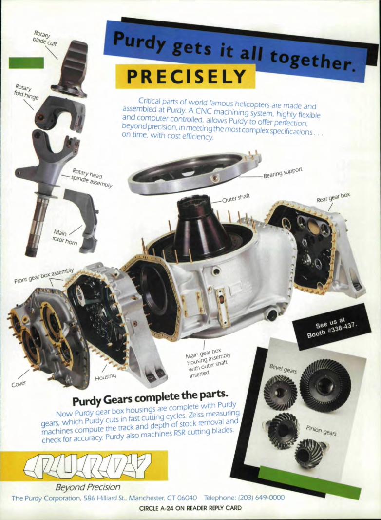
bOllRear gear
/
Rotarybla(j~CUff1_""
Critical parts of world famous helicopters are made andassembled at Purdy A CNC m.3chining system, highly flexible.3nd computer controlled, allows Purdy to offer perfection,beyond precision, in meeting the most complex specifications. , .on time, with cost efficiency
Co'IJer
- - ~ - m ' 'Iete the Ip~rts"Purdy Gears co_ P m 'lete With PUf?y- ear box hOUSingsare co P Zeissmeasunng
Now Purdy g ln fast cutting cycles, oval andhich purdy cuts I _ de th of stock rem
gears,.w ute the track and ~ RSR cutting blades.machines camp Purdy also machines _.check for accuracy. -
Beyond PrecisionThe Purdy Corporation, 586 Hilliard St.• Manchester, CT 06040 ,',' ,___
- , CIRCLE A-24 ON IREADER IREPlY CARO

51 UNITS - MEASUREMENTS ...[continued from page 48)
Acceleration: angular1 degree I se2 is 0'.0175 rad/s2
Angle1 degree is 0'.0175 rad1min is 0'.291 mrad
Area1acre is 4047 m2
1tt2 is 0.093 m2
1 hectare is 0.01 km2
1 in2 is 645 mm2
1 yard2 is 0.836 m2
Coefficient of thermal ex~~on11°F ~ 1 ..BIK
Density (i.e.,. specific mass. For rdative densitY seespecific gravity.)11bm/ft31 Ibmlin3
1Ibm/gal. (US)1kg/dm3 or glcm3
15 16.02 kg/mJ
Mg/m3
kg/m3
kg/m3
is 27.68is 119.8
1000.is
Note: The m and f subscripts are intended to distinguish be-tween the two meanings of oz., lb., ton and the like. Whenthese units refer to mass, the subscript m is used; when toforce, the subscript f is used. In S[, the unit of mass is formedfrom the word gram, and the unit of force from the wordnewton .. Whereas Ibm and lbf are numerically the same fora given object on Earth, newton and gram differ. TheIbm/lb{ distinction can be ignored in the commonmeasurements of daily life, as the distinction makes no dif-ference there ..In some branches of engineering, however, andin converting to SI units, understandng the distinction is vitalfor avoiding 'errors. Some specific weight tables list the valuesderived from force' units, not mass units ..The potential errorresulting from the use of the above conversion factors is 0to 0.5%.
Dimension (is always in mm in Mech. Eng.)1 ft is 3051 in1 yard
isis
25.4914
Energy: general (including work)1 Btu is 1.0551 cal (thermochemical) is 4.191 Cal (usage in nuer.) is 4.191 ft-Ibf is 1 ..361 kg-m is 9.811 kW-hr is 3..6Note: kg" -kg force, sometimes written kp.
Energy: specific1 Btu/Ib.,1 calzg
kJJkJJJMJ
kJ/kgkJ/kg
isis
2.334.19
50 Gear Tecr'lnology
Flow: mass1 Ibm/min is 7.56 g/s1 IbmI sec is 0.454 kg/s
Flow: volumetric1 ftJ Imin is 0.472 dmJ/s1 gal (US)/h is 1.0'5 cml/s1 gal (US)/min is 63 cml/s
Force (ind. load, weight, etc., where they pertain to force)1 dyne is 0.01 mN1 kg** is 9.81 N1 OZf is 0.278 N1 lb, is 4 ..45 N1ton (short) force is 8.90 kN1 ton (metric) force is 9.81 kN
Frequency: cycle1cpm is Hz1160
Frequency: rotational1 rpm is 1160 lisNote: lis = 5-1. Both symbols represent the SI unit of rota-tional frequency, popularly known as speed, speed of rota-tion, revolutions per second, rps, and the like.
Fuel .consumption: transportation (inel. economy)1 Ibtn/h is 0.126 glsx liter 1100 km is 1001 x km/dmJ
1 mile/gal (US) is 0'.43 km/drrr'Note: 235.21mpg - liter per 100 km
235.2/liter per 10'0 km ~ mpg
Fuel consumption: sEecific1 Ihm/hp (US)-h is 169 Itg/]1 g/kW-h is 0.278 ,ugl}
Length (See also dimension.)1 ft is 0..305 m1 in is 25.4 mm1mile (nautical) is L8S km1mile (statute) is 1.61 km1 yard is 0.91 m
Mass (incl. load, weight, etc., where they pertain to mass)1 carat is 0.2 g1 OZm (avoirdupois)1 oZm (troy)1 Ibm1 slug1 ton (short) mass
Modulus of: elasticity1 Ibflin
2
Modulus of: section1 in3
Moment of: area,. 1st1 in3
is 28.35 gis 31.10 sis 0.454 kgis 14.6 kgis 0.907 Mg
is 6.89 kPa
is 16.4 ,cm3
IS 16 ..4 em3
is 41.6 cm4
(continued on page 52)
Moment of: area, 2nd1 in4

..
@ryant"
,& Vlisit IU.S,,at.. Booth #534.,
Mr. Waltekus states, "We could see the Increasedproductivity and multiple machine capabilities theLectraline had to offer." Mr. Flores adds, "With theBryant we have experienced less scrap, less rework, ahigher quality product, and production done In a fractionof the original time." Waltekus concludes, "The BryantLectraline more than met our expectations. The serviceand assistance we have received has been outstanding.Having the fullest confidence In the machine'sperformance we ordered a second."
If you're interested in quality and performance for yourgrinding operations contact Bryant Grinder Corporation,Springfield, Vermont 05156, (802) 885-5161.We'lII show you how to get it.
Bryant Grinder Corporation I Subsidiary of Textron Inc.
CIRCLE A-7 ON IREADER IREPLYCARD
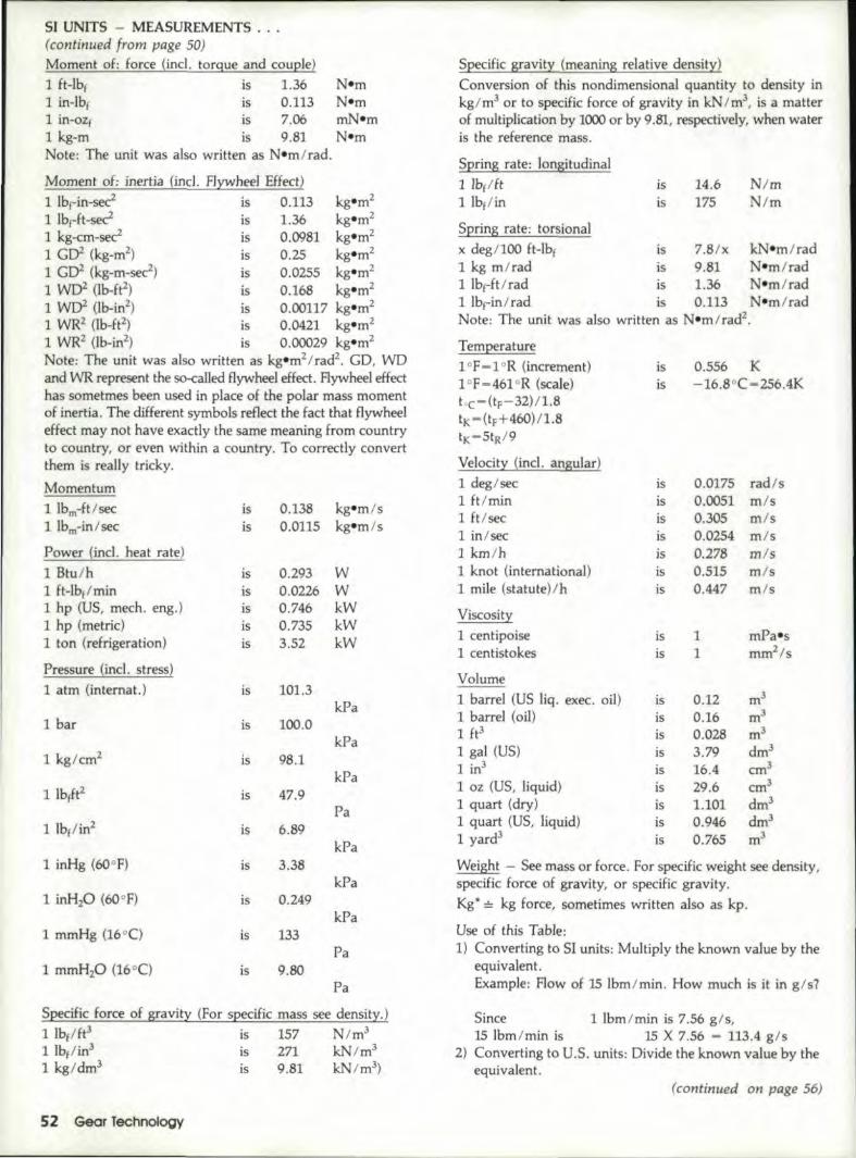
SI UNITS - MEASUREMENTS ...(continued from page 50)Moment 'Of: force (incl. torque and cDuple)1 ft-Ibf is 1.36 Nem1 in-lb, is 0.113 Nem1 in-ez, is 7.06 mN-m1kg-m is 9.81 NemNote: The unit was also written as Nsm/rad.
Moment 'Of: .inertia (inel. Hyw:heel Effect)1 Ibf-in~sec2 is 0.113 kgem2
I1bf-ft-sec2IS 1..36 kgem2
1 kg-em-sec' is 0.0981 kgem2
1 GIY (kg-m2) is 0.25 kgem2
1 GIY (kg-m-seei) is 0..0255 kgem2
1 WOZ Ub-ft2) is 0..168 kgem2
1 WD2 Ob-in2) is 0 ..00117 kg.m2
1 WR2 (lb-ft'') is 0.0421 kg-m2
1 WR2 (lb-in2) is 0.00029 kgem2
Note: The unit was also written as kgem2/rad2• GO, WDand WR represent the so-called flywheel effect, Flywheel effecthas sometmes been used in place 'Of the polar mass momentof inertia. The different symbols reflect the fact that flywheeleffect may not have exactly the same meaning from countryto country, or even within a country. Tocorrectly convertthem is really tricky.
Momentum1 Ibm-fUsee is 0.138 kg-m/s1 Ibm-in I sec is 0.0115 kg-m/s
Power (incl. heat rate)
1Btu/h is 0.293 W1ft-Ibf/min is 0.0226 W1 hp (US, mach. eng.) is 0.746 kW1hp (metric) is 0.735 kW1ton (refrigeration) is 3.52 kW
Pressure (incl. stress)1 atm (internat.) is 101.3
kPa1bar is 100.0
kPa1kg I cm2 is 98.1
kPa1 Ib(Itz is 47.9
Pa1 Ibl/in2 is 6.89
kPa1 inHg (60of) is 3.38
kPa1 inHzO (60or) is 0.249
kPa1 mmHg (16°e) is 133
Pa1mmH20 os-o is 9.80
Pa
Specific f.orce ·of gravity (For specific mass see density.)1 Ibf/ft3 is 157 N 1m3
1 Ibl/in3 is 271 kN 1m3
1 kg/dm3 is 9.81 kN/m3)
.52 Gear Technology
SpecificSI;avity (meaning relative density)Conversion of this nondimensional quantity to density inkg/rrr' or to specific force or gravity in kN 1m3, isa matterof multiplication by 1(X)() or by 9.81, respectively, when wateris the reference mass.
Spring rate: longitudinal1 lb(lft1lbflin
14.6175
NlmN/m
isis
Spring rate: torsionalx deg/lOO ft-Ibf is 7.8/x kN-m/rad1 kg m/rad is 9.81 N-m/rad1 IbrfUrad is 1,36 Nem/rad1 Ib,in/rad is 0.113 Nern/radNote: The unit was also written as Nsm/rad".
Temperature1 °F-1 =R (increment)1 °F=461 oR (scale)toc-(tF-32)/1.8tK-(tF+ 460)/1.8tK-StR/9
Velocity (ind. angular)1deg/sec1 It/min1Ft/sec1 in/sec! km!h1 knot (international)1mile (statutel/h
isis
0.556 K-16.8°C-2S6.4K
is 0.0175 rad/sis 0.0051 mlsis 0.305 m/sis 0.0254 m/sis 0.278 m!sis 0 ..515 m/sis 0.447 m/s
is 1 mPa.-sis 1 mm2/s
is 0.12 m3
is 0.16 m3
is 0.028 m3
is 3.79 dm3
is 16.4 cm3
is 29 ..6 cm3
is 1.101 dm3
is 0.946 dm3
is 0.765 m!
Viscosity1 centipoise1centistokes
Volume1 barrel (US liq. exec. oil)1 barrel (oil)1 ft3I gal (US)1 in3
1 oz (US, liquid)1 quart (dry)1 quart (US, liquid)1 yard3
Weight - See mass Dr force. FDr specific weight see density,specific force of gravity, or specific gravity.Kg*~· kg force, sometimes written also as kp.
Use of this Table:1) Converting to 51 units: Multiply the known value by the
equivalent.Example; How oJ 15 Ibm/min .. HDW much is it in g/s?
Since 1 Ibm/min is 7 ..56 g/s,15 Ibm/min is 15 X 7.56 - 113.4 g/s
2) Converting to U ..S ..units: Dividethe known value by theequivalent.
(continued on page 56)

IUL-T'RA-,CA:SE:™IH'iglhspeed inductioln gea'r hairdleniin'g
cuts, IClo,sts andl lelliim'in!8t'e:sc8lrbluri,z,ingl
• Eliminat'es cali'buli'iz:ing'.,• lis easily integralt'ed iinto your gear
manufa.cturing celli.'.' Eliminates dimensional diist,ortion problems.• IReduces over,all manufacturin.g costs.• IProcesses a wide v,ariety of gear,s.,• IUtiilizes proven high pe.rforman,c,e tech,nology.The new IEH50 1KHzsolidi state U[TRA~CASESystem offers you surface hardened gears atproduction line speeds. ULTRA-CASE enables youtoharden g:ears twice' astast as any other .comparable lnduction system with less equipmentand at lower cost.
_ See us in Booth #324.
,AN AJAX MAGNETH!ERMIC GROUP C'O:MPANV
Unililkecurrently available systems, UtTA'A-CASErequires no pre-heat cycle which often affects corehardness. ULTAA~CASE 501KHz also elimtnatesthe use of outmoded RF sets.Let Industriall Elect,ric Heating put ULTRA-CASE. towOf,kfor you. Send usa sample part or let us makea production run. We can even handle some ofyour heat treating jobs in our plant. For more'information, wrlte to:IndustrialllElectric Heating:, 3949' !lyman Drive.!Hilliard. Ohio 43026; Phone (614) 876-045'6, orP.O. Box 991, Wam;m, Oh,io 44482; or call(216) 37.2~8574,telex 9'82482, fax (216) 372-8644 ..
CIRCLE A-21 ON READER IR.iPLV CAR,D

Closlngl da,1e: Ads must be' 'received by the25th of the month •.two months prior topublication. Acceptance: Publisher reservesthe right to accept or reject classifJed adver-tisements at his discretion .
Rates: Classified Dispfay-$110 per inch(minimum 3D
) Type will be set to advertiser'slayout or Gear Technology will set type .at noextra charge'.Woral'Coun,t: 35 charactersper line, 7 lines per inch.
GEARS·SPLINESDESIGN AND TOOUNGI
.. Custom gear design including non-standard pressure angles for morestrength.
• IProgr.ams to enter tOOling data in-to computer files and search for ex-isUng cutters to cut a new gear orspline.
• Gearing computer software forsale,
• Consulting services for gear andsp'line problems.
VAN GERPEN·R,EECE, ENGINEERING1502 Grand Blvd.
Cedar iFalls, Iowa 50613(3191266 4674
CIRCLE A·38 ON: READER REPLYCARD
HOB!B:ER IREBUILD'INGISPECilAUSTS
Having trouble meeting todays de-mand quality control tolerances?Let our factory trained and ex-perienced staf return yourmachine to optimum operat'ingcondition. -We specialize in repairing.rebuilding: and modernizing allmakes of hobbers.
• Cleveland Rigidhobbers• Gould &. IEberhardt• sarber Colman
PRESSfIrIATl'ON liNe ...522 Cottage Grove RoadBloomfiel'd, Conn. 06002
(20G) 242:-8525CIRCLE A-411 ON READER REPLY CARD
Bring in new customersfor your busmess by advertiSing In
GEAR TECHNOLOGY.The Journal of Gear Manufacturing.
Can 1312,' 437-6604
54 Gear Technology
IPayment: Full payment must accompanyclassified ads. Mail copy to Gear Technology.P.O. Box 1426. Elk Grove Village, IL ,60007.A.gellcy CommisslClII: No agency cemmis-sion on classif.ieds.
GEAR ES,TIMATINGThe COSTIMATOR® computer
aided cost estimating system insuresspeed and consistency in the difficulttask of estimating the costs of allty,pes of gears.
Used by small shops and Fortune500 companies througihout thecountry.
For complete informationcontact us today.
IManufacturers Technologies, line ..59G Interstate Dr.
West Springfield, MA 01089'(413) 733-1972
CIRCLEA.-39 ON READER REPLV CA~RD
G.EAR TOOTH ,GRINDING& HONING ONLY
ProdUcti.on Quantities3/4" P.O. to 27.5" P.O.;3.5 IO.P. and 11" Face
Gear liooth Finishingis our Only Business
We have no turning, hobbing orshaping capability
Alt,EGH,ENY GEAR CORP.23 Dick. Road
Depew, NY 14043716·684-3811
CIRCLEA-42 ON: READER REiPlV CARD
There's still time ...cl'osingl date for a classified adin the Nov./Dec. issue isSept. 25th
• GEAR DESIGN •- '& ' ,ANALYSIS :PROGR~MS
IFORIBM COMPATIBL,EWorm,. Spur., Helicalwill be demonstrated
at IBOOTH 805IBuckingham Gear Books
also available
For more info call:'Buckingham Associates, line.
59,1 Parker HillSpringfield, VT 05156
Tel. 802'-885:'5052
CIRCLE A-43 ON: READER REPl V CA_RD
SE'RV'IC:E:A·· I r Ina,YJca
'Gear MeasuriingInstruments
'PRECISE INSPECTION27380 Gratiot Avenue
Roseville, Michigan 48066313-445-6959
CIRCLEA-4' ON READER REPLY CARD !i
HELP' WANTEDWANT,ED: 'Gear set up man for closetolerance work on late model gear
II machinery. Requirements: shaping, nob·
l
b. ·.I.n..g_ B.ndti inspec. tion ex.p.erien ..~..e.. M.idwest·ern location; goodl pay and fringes. Sendresume to: Box AT, Gear Tectlnology,P.O. Box 1426,Elk Grove, IlL 60007

'Quality,Techno.'ogy,IExper,ience"Function.alClh,aracte'r:,I ..nvestlgatlon •••
IINSERT' BLAIDE IH:OBS
SYSTEMFHUSAhobs. withinserts blades. me developed by anexperienced team, mode with the beststeels and accurately controlledcoatings.FHUSAis ready to design the hobyou need. however ,hard It maybe the work to be developed.
MADE lay AtIlSA, THE CHAULNGI: OF A_NOllOlNTHAT ,GUARANTEES ITS I,EFFIC'IENCY.
AMIIHCO.American Inserted Hobs IntI.PoD. BOX 2837 BROOKLYN, INY. 1120.2 Tel 718-624-1'607TLX. 428789 AMIH~MIIHICO .•, NEW YORK, LONDON, DUSSELDORF, PARIS,CIRCl!E A-25 ONi R,EADER REPLY CARD

-- - ---
I TECH~T)C-,UCALI~XD~\I'
51 UNITS - MEASUREMENTS ...(continued from page 52)
Example: Flow of 15 g/s. How much is it in Ibm/min?
Since 1 Ibm/min is 7.56 gis,15 g/s is 15 -+- 7.56 - 1.98 Ibm/min
3) Converting when the x is in the formula: Place the knownvalue for the x.Example: Fuel consumptionof 20 literl100 km.
How much is it in km/drrr'ISince x Hterl100 km is 100/x km/drrr'20 IiterllOO km is 100/20 = 5 km/dm3
Rounding Oft Converted NumbersOne frequently encounters complicated, beyond-the-
decimal point "accurate" conversions. Following are typicalcases indicating practical considerations one must apply whenconverting.
Torque - Torquevalues, when they refer to fasteners, areinherently inaccurate. They are usually rounded off to a sim-ple number within 20% of the nominal value. Therefore, thedata in Nem will seldom need to be expressed in numbers
SEPTEMBER 16-18GEAR NOISE SEMINAR-Ohio State University.This course will cover general noise measurements andanalysis. causes of gear noise, gear noise reductiontechniques, dynamic modeling. gear noise signal analysisand modal analysis of gear boxes. For further informa-tion. contact Mr. Richard D. Frasher. Director of Continu-Ing Education, College of Engineering, 2070 Neil'Avenue, Columbus, OH 43210. (614) 292-8143.
OCTOBER 4-6AGMA - GEAR EXPO 'S7Clncmnan Convention CenterCincinnati, OH
OCTOBER 5-7AGMA - FALL TECHNICAL MEETINGHyatt Regency CincinnatiCincinnati, OH
For further information contact: AGMA 1500 King St..Suite 201, Alexandria. VA 22314 (703) 684-0211.
OCTOBER 7-9COMPUTER-AIDED GEAR DESIGN PROGRAMWisconsin Center, Madison, WIThe University of Wisconsin-Milwaukee presents a three-day seminar for enqmeers designing and specifyinggears or gear drives. It will provide a frame work inwhich the student may develop a computer-aided
56 Gear Technology
more precise than rounded off to the nearest 5 Nem or a unitvalue.
Example: 15-18 ft-lb (20-25 N·m)not 20.3-24 ..4 N-m50-60 in-lb (6·7 N-m)not 5.7-6 ..8 Nsm
For very small values, no greater precision than 0.5 N isneeded.Example: 10-1 in-lb (I-1.5 Nern)
not 1..13-1.7 N·m
Dimension - A statement that something is 20 inches longmay mean a length of between 19 and 21 inches if it is a.pieceof firewood or 20.000 inches if it is a part ofa machine.Similarly, 2.625 inches may mean a length of between 21/zto 2% inches or exactly 2.625 inches. The knowledge of ap-plication and circumstances involved in making the measur-e--ment is needed to determine conversion precision. The 20inches may correctly be converted to both liz m and 508.00mm, the choice depending on the origin and purpose of theinformation.
design system for his or her individual needs. BaSICSofboth gear design and use of microcomputers will becovered. For more information. contact John M.Leaman, Center for Continuing Engineering Education,Univ. of Wisconsin-Milwaukee, 929 North Sixth Street.Milwaukee, WI 53203. (414) 227-3110.
NOVEMBER 17-19SME GEAR PROCESSING & MANUFACTURINGCLINICMichigan Inn, Southfield, MIThree days of presentations and discussions. Topics tobe covered include gear finishing. hardening. broaching.grinding. shaping, inspection and chart evaluation,brush finishing and deburring, hobbing and hob deSIgn.choice of materials for cutting tools and shaper cutterdesign. Tuesday evening Nov. 17. will feature tabletopexhibits of the iatesr gearing products. For more informa-tion about attendance of exhibition space. contact JoeFranchini at SME. One $ME Drive. P.O. Box 930. Dear-born, MI. 48121. (313) 271-1500, ext. 394.
CALL FOR PAPERS
Deadline for submissions for this spring, 1989. conference isDecember 31, 1987. For more information contact: DonaldL. Borden. P.O. Box 502. Elm Grove. WI 53122. r414)784-9363.
ASME 5TH INTERNATIONAL POWERTRANSMISSION AND GEARING CONFERENCE

~w_ii.~~'machining needs,· cuts the leading edge.
SA25CNC
Gear Culling Tools
SPECIACATIONS
Mitsubishi mechanical and electronic technologies cometogether today in a full lineup of the most advanced gearculting machines on the market. Whether YOIH requirementscall for hobbing, gear shaping or gear shaving, includingflexible gear manufacturing systems, Milsubishi offers theideal solution for any need. All machines are unsurpassedin flexibility, speed, accuracy and rigidity - resulting innew standards of productivity. For full mformafion on theentire lineup, along wilh available tools, contact us today.
Mill. MiIII Mam IoIIJ!Q(Macn,",
Model Workpiecll WDrkp eee[HP) W,~nl
[)Iii (In) Pitch (D P 1 IlbslGA15CNC 5.9/1 9 6.35 10 8800GA25CNC 98 4 10 17600
Gear HobDlirs GA40CNC 157 4 10 18700GA.63CNC 24.8 1.8 20 24,200.-SA25CNC 98 4 75 11000
Gear Snapers SA40CNC 157 4 10 1S 600SA6JCNC 25 B 3.2 24 1 2(100--f- f----
Gear Shavu FA30CNC 12.2 3.2 15 1I.~
GEAR EXPO '87Booth 11323
MITSU ISHI Mitsubishi Heavy InduBtries America, Inc.87. Supreme O. Berl! ......llfe IL 60'06 Phone (3121 860-4220
HEAVY INDUSTRIES. LTD.5-1. Marunouchl 2-cP1Ome, Ctllyoda-ku. Tokyo, Japan Mitsubishl International CorporatIon
Cable Address HrSHIJU TOKYO 673 Supreme Drive, Bensenville. IL 60106 Phone (312) 860-4222
CIRCLE A.-8 ON REAOER IREPLYCARO

hlBl1E'EBrTH/IB' YIU1IIIYBIIlIAI'"PRIBIC/IIB'BlAIS'The production of parallellolaxfsspur andl helical - ,gears has, JUst,undergone such a ,maJor ,change thatmost: ,mach,f'nery tn use today Is:obsolete'"Gleason CNC Systems compatible 'hob-bing rnachnes have written a wholenew set of rules,on how to produce spurand helical ,gearsprofitably. The GleasonCNC nobbers offer highest volume,highes[ degrees of flexibility and fastestchangeover. Whafs more you can getautomatic hob andfiXlure change plusautomatic part load/unload.That's why auto transmission plants,throughouf the world are equippedl withGleason nobbers. And (hat's whyGleason's production ho.bbing capabilityis rapidly becoming the wond st:anda~dfor gear production.The rear 'Greason prus is the worldwidenetwork of service andapplicat,ionengineering support that Gleason pro-vides. The result consistently is this:maximum equipment reliability, maxi-mum uptime and highest quality gearoutputCaUnow to ream more about the paral-lel-axis gear produaion of today - andtomorrow. The Gleason Works. 10001University Avenue, Rochester. NY 1469'2.Detrojt 131'31 353-5205,
GleasonTh. Warld af ca•• ring
SEE USAT ,G~ IEXPO''87BOOTHI419
CIRCLE A·20 ON READER ,REPLYCARD'

Vol. I, No. 1 May/Jlune 1984Single Flank Testing of GearsAc.lVantagesof Titanium Nitride Coated
Gear ToolsCNC Controlled CBN Form Grinding..Back to Basics. . . " Gear Design
Vol. I, No•.2 Au ./Sept. 1984Precision Forged Spiral Bevel GearsIdentification and Correction of Damaging
Resonances in Gear DrivesMaximum Surface Temperature of the
Thermoplastic Gear in a Non-lubricatedPlastic/Steel Gear Pair
Economics of CNC Gear Gashing vs. LargeD.P. Hobbing Determinationof Gear RatiOS
"Back to Basics .... Functions of Gearingand Application of the Involute to GearTeeth
Vol..I, No.3 Oct.lNov.1984Endurance limit for Contact Stress In
GearsCone Dove Double Enveloping Worm Gear·
ing Design & ManufactunngGear Generating USing Rack CuttersScoring Load Capacity of Gea s Lubricated
With EP-OllsAustempered Ductile Iron"Back to Basics., .. Design of Involute
Gear Teeth
Vol. 2, INo. 1 J ./Feb. 1985AnalYZing Gear Tooth As A Function of
Tooth Contact Pattern Shape andPosition
Computer Aided Design (CAD) of Forgingand Extrusion Dies for the Pwductlon ofGears by Forming
The Effect of Lubricant Traction on Worm·gear Efficiency
High Power Transmission with Case-Hardened Gears and Internal PowerBranching
"Back to Basics.. .. Definitions of GearElements
Vol. 2, No.2 M rch/Apri 1985Hard Gear Processing with Skiving HobsInvolute Spline SIZe tnscecnonAustempered NOdular cast IronsTolerance for Overload StressTooth Forms for HobsGear Grinding Teehruques Parallel Axis
Gears
Vol. 2, No. 3 Ma),/Jlune,1985Gear Tooth Scoring Design Considerations
for Spur & Helical GearingAdvantages of Involute Splines as corn-
pared to Straight Sided SplinesThe Design & Manufacture of Machined
PlastiC Gears - Part 1"Back to Basics ... " Gear Inspection &
Chart Interpretation
BACK ISSUiE INDEXV·oI. 2, INo. 4 JulylAulust 1985,DynamiC Analysis of Straight and Involute
Tooth FormsInfluence· of Relative Displacements
Between Pimon and Gear on Tooth RootStresses of Spiral Bevel Gears
The Design & Manufacture of MachinedPlastiC Gears - Part II
Longitudinalloadl Distribution Factor ofHelical Gears
Factors Affecting Shaper Cutter Selection"Back to Basics, .... Material Selection &
Heat Treatment. Mechanical Properties- Part I
Vol. 2, No.5 Sept./Oct. 1985Calculation ot Spur Gear Tooth Flexibility
by the Comples Potential MethodHob Length EffectsSingle Flank Data Analysis and
tnterpretanonNew Techmques for Aligning and Maintain·
ing Large Ring Gears"Back to Basics ... " Material Selection
and Heat Treatment - Part III,Metallurigical Characteristics
Vol 2. No.6 Nov./Dec:. 1985Calculation of Slow Speed Wear of
lubncated GearsGeneral Equations of Gear Cutting Tool
CalculationsFinding Gear Teeth RatiosTechnological Fundamentals of CBN Bevel
Gear Fin~shGrinding"Back to Basics, , , "-Gear Shaping
Machines CNC DevelopmentVol. 3, No. 1 Jlan./F.b. 1986Lower Grinding Cost and Better Workpiece
Quality by High Performance Grindingwith CBN Wheels
Optimum Number of Teeth tor SpanMeasurement
Effect of Shot Peening on Surface Fatiguelife of Garburized and Hardened AISI9310 Spur Gears
"Back to Basics, , ." The Process of GearShaVing
Vall. 3, No.2 March/Apr 198·8A Computer Solution tor the Dynamic
Load, lubricant Film Thickness, and Sur·face Temperatures in Spiral·Bevel Gears
CNC Gear ShapingControlling Tooth loads in HelicaJ Gears"Back to BaSICS .... Design & Selection
of HobsVol. 3, No.3 MaylJune 1986A Wheel Selection Technique for Form
Gear GrindingIdentification of Gear Noise with Single
IFlank Composite MeasurementSelection of Material and Compatible
Heat Treatments for Gearing"Sack to Basics . .... Generating &
Checking Involute Gear Teeth
Vol. 3,NG. 4 JulylAul. 1986Mechamcal Efficiency of Differential
GearingEffect of MoS2 Films on Scoring
Resistance of Gears"Back to Basics .v ." Bevel Gear Develop-
ment and Testing Procedure
Vol. 3, No.5 Sept./Oct.1986Improved Gear life Through Controlled
Shot PeeningPractIcal Analysis of Highly·Loaded Gears
by Using the Modified·Scoring Index.Calculation Method
Tooth Strength Study of Spur Planet GearsPressure Angle Changes in the Transverse
Plane for Circular Cut Spiral Bevel Gears"Back to Basics. , ." Gears for Non·Paraliel
ShaftsVol. 3, No.6 Nov./Dec.1986Kinematic Analysis of Robotic Bevel-Gear
TrainsMirror Finishing of Tooth Surfaces Using a
Trial Gear Grinder with Cubic·Boron·Nitride Wheel
A Logical Procedure to Det rrmne ImtialGear Size
"Back to Basics ... " CUfVlCCouplingDesign
Vol. 4, No. I .Jan.lFeb. 1981Lubricant Jet Flow Phenomena in Spur &
Helical GearsGear Noise and the Sideband PhenomenonImprovement in toad capacity of Crossed
Helical Gears"Back to Basics ... " Gear ManufactUring
Methods - Forming of the TeethVol. 4, No. 2 MarchJ~pril1987The Effect of Reverse Hobblng at a High
SpeedChecking Large GearsInfluence of Geometncal Parameters on
the Gear Scuffing Criterion - Part IAppreciable Increases in Surface Durability
of Gear Pairs With Mlrror·like Fimsh"From the Industry. , . " Crowning: A
Cheap Fix for iNoise Reduction andMisalignment Problems and Applications
"Back to Basics, , ," Economics of CNCGear Hobbing
VoIl. 4, No.3 May/Jlune 1987Gear Design OptionsInfluence of Geometrical Parameters on
the Gear Scuffing Onterlon - Part IIHard Cutting - A Competitive Process In
High Quality Gear Production"Back to Basics ... " Gear RolI·Fimshing"Back to Basics . , .' IRotary Gear Honing
Vol. ,4, No.4 JulyJAulust 1981Longitudinal Load Distribution Factor for
Straddle-and Overhang· Mounted SpurGears
Helical Gears with Circular Arc Teeth:Simulation of Conditions of Meshing andBearing Contact
"Back to -BasIcs ... " Cutting FluidSelection and Process Controls for theGear Manufacturing Industry.

h'SET"ERrl11I1B ",
The production ,ot paraUel-axJs -spur and helical - gears has Justundergone sucha m ~orchange thatmost machinery In use today Isobsolete.Gleason CNC Systems compatible hob-bing machines have written a wholenew set of rules on how to produce spurand helical gears profitably. The GleasonCNC hobbers offer highest volume.highest degrees of "exibWty and fastestchangeover. What's more you can getautomatic hob and fixture change plusautomatic part load/unload.That's why auto transmission plantsthroughout the world are equipped withGleason noboers. And that's whyGleason's produaron hobblng capabilityis rapidly becoming the world standardfor gear prooucnonThe real Gleason plus is the worldwidenetwork of service and applicationengineering support that Gleason pro-vides. The result consistently is this:maximum equipment reliability. maxi-mum uptime and highest quality gearoutput.
Call now to learn more about the paral-lel-axis gear production of today - andtomorrow. The Gleason Works. 1000University Avenue, Rochester, NY 14692.Detroit 1313.1353-5205.
GeasonThe Warld af Gea,rln'g