theeffectofkerrnonlinearity,doppler …prr.hec.gov.pk/jspui/bitstream/123456789/2833/1/hazrat... ·...
TRANSCRIPT
THE EFFECT OF KERR NONLINEARITY, DOPPLER
BROADENING AND SPONTANEOUS GENERATED
COHERENCE ON SLOW LIGHT PROPAGATION
by
Hazrat Ali
A Dissertation
Submitted To The University Of Malakand In Partial Fulfillment Of
Requirements For The Degree Of
DOCTOR OF PHILOSOPHY
In Physics
Major Professors: Prof. Dr. Iftikhar Ahmad
Asst. Prof. Dr. Ziauddin
DEPARTMENT OF PHYSICS UNIVERSITY OF MALAKAND,
CHAKDARA, PAKISTAN
2016
i

ii

Abstract
The influence of Kerr non-linearity, Doppler Broadening and spontaneous
generated coherence (SGC) is presented when a probe light pulse is incident
on dispersive atomic medium. We consider different atom-field configura-
tions, i.e., N -type electromagnetically induced transparency (EIT), Four-
level Λ-type and tripod atomic systems. Initially, we consider a four-level
N -type atomic medium and exploited the light pulse propagation through
the medium. It is found that the Kerr non-linearity and relaxation rate of
forbidden transition affect the dispersive properties of the atomic medium.
A more slow group velocity of light pulse propagation is achieved via in-
creasing the Kerr field. We also explored the influence of relaxation rate
of forbidden decay rate on dispersive properties of the atomic medium. By
increasing the atomic number density, the relaxation rate of forbidden de-
cay rate increases which leads to control the slow and fast light propagation
through the medium. Next, we consider a four-level Λ-type atomic medium
and investigated the influence of Kerr non-linearity and Doppler broadening
on the dispersive properties of the medium. It is found that the combined
effect of Kerr non-linearity and Doppler broadening influence the dispersive
properties of the atomic medium more sharply as compared to separate effect
of Kerr non-linearity or Doppler broadening. The combined effect of Kerr
non-linearity and Doppler broadening on light pulse propagation then leads
to a more slow group velocity through the medium. Further, we included the
SGC and Kerr non-linearity in four-level atomic system and study the light
pulse propagation through the medium. A very steep dispersion is achieved
via the combined effect of SGC and Kerr non-linearity. A steep dispersion
then leads to more slow group velocity through the medium. Next, we ex-
tended our studies to the propagation of light pulse propagation to four level
iii

tripod atomic medium via two Kerr nonlinear fields. We expect That a very
slow group velocity can be achieved, which in turns leads to stop or halt the
light pulse through the medium.
iv

Acknowledgements
I acknowledge the support of all those people who helped me directly or in-
directly in the completion of this dissertation. I am grateful to my supervisors
Dr. Iftikhar Ahmad and Dr. Ziauddin (CIIT, Islamabad) for their kind su-
pervision, discipline, guidance and encouragement during my research work.
I am very thankful to Dr. Joseph. H. Eberly for hosting me at the university
of Rochester, USA, and providing me the opportunity to learn from his expe-
riences. I am also thankful to all the faculty members of the Department of
Physics, graduate students of the Center for Computational Materials Science
and Joseph. H. Eberly group especially Mr. Saifullah, Dr. Shafiq Ahmad,
Dr. Imad, Dr. Zahid, Mr. Bilal, Mr. Sheraz, Mr. Banaras Khan, Mr.
Fawad Khan, Mr. Rashid Iqbal, Mr. Sajid Khan, Mr. Amin Khan, Mr. Gul
Rehman and Mr. Philippe Lewalle for facilitation and providing a friendly
working environment. I would like to say the words of thanks to my friends
Jan Muhammad and Shakir Khan for their cooperation in my research work.
I gratefully acknowledge the financial support of the IRSIP section of the
Higher Education Commission of Pakistan for my visit to the University of
Rochester. Most importantly, my deepest love and gratitude will go to my
parents and siblings for their love, patience and support throughout my stud-
ies. Special thanks to my wife for her moral support during the process of
the completion of my Ph. D. studies and love to my kids Sara Khan, Yaman
Khan and Abyan Khan.
Hazrat Ali
v

List of publications
This thesis consist of the following published papers
1. Hazrat Ali , Ziauddin, Iftikhar Ahmad “Control of wave propagation
and effect of Kerr nonlinearity on group index,” Commun. Theor. Phys. 60,
87-92 (2013).
2. Hazrat Ali , Ziauddin and Iftikhar Ahmad “The effect of Kerr non-
linearity and Doppler broadening on slow light propagation,” Laser Phys.
24, 025201(1-5) (2014).
3. Hazrat Ali , Iftikhar Ahmad and Ziauddin, “Control of Group Veloc-
ity via Spontaneous Generated Coherence and Kerr Nonlinearity,” Commun.
Theor. Phys. 62, 410-416 (2014).
Other publications
4. Bakht Amin Bacha, Iftikhar Ahmad, Arif Ullah and Hazrat Ali ,
“Superluminal propagation in a poly-chromatically driven gain assisted four-
level N-type atomic system,” Phys. Scr.. 88, 045402(1-7) (2013).
5. J. H. Eberly, Xiao-Feng Qian, Asma Al Qasimi, Hazrat Ali , M. A.
Alonso, R. Gutirrez-Cuevas, B. J. Little, J. C. Howell, Tanya Malhotra and
A N Vamivakas, “Quantum and classical opticsemerging links,” Phys. Scr..
91, 063003(1-9) (2016).
vi

vii

Contents
1 Introduction 1
2 Literature Review 7
2.1 Origin of Slow Light . . . . . . . . . . . . . . . . . . . . . . . 7
2.2 Dispersion . . . . . . . . . . . . . . . . . . . . . . . . . . . . . 9
2.3 Slow Light . . . . . . . . . . . . . . . . . . . . . . . . . . . . . 10
2.4 Experimental Realization of Slow Light . . . . . . . . . . . . . 12
2.4.1 Coherent Population Trapping . . . . . . . . . . . . . . 12
2.4.2 Coherent Population Oscillations . . . . . . . . . . . . 12
2.4.3 Stimulated Brillouin Scattering . . . . . . . . . . . . . 13
2.4.4 Stopped Light . . . . . . . . . . . . . . . . . . . . . . . 13
2.5 Electromagnetically Induced Transparency . . . . . . . . . . . 15
2.6 Nonlinear Optics . . . . . . . . . . . . . . . . . . . . . . . . . 17
2.6.1 Kerr Effect and EIT Kerr Non-linearity . . . . . . . . . 19
2.7 Doppler Broadening . . . . . . . . . . . . . . . . . . . . . . . . 22
2.8 Spontaneous Generated Coherence . . . . . . . . . . . . . . . 24
3 Calculation Details 27
3.1 Density Matrix Formalism and Rotating Wave Approximation 28
3.2 Liouville’s Equation . . . . . . . . . . . . . . . . . . . . . . . . 30
3.3 Hamiltonian in the Rotating Wave Approximation . . . . . . . 32
viii

4 Results and Discussion 39
4.1 Control of Wave Propagation and Effect of Kerr Nonlinearity
on Group Index . . . . . . . . . . . . . . . . . . . . . . . . . . 39
4.1.1 Introduction . . . . . . . . . . . . . . . . . . . . . . . . 39
4.1.2 Model . . . . . . . . . . . . . . . . . . . . . . . . . . . 42
4.1.3 Presentation of the results . . . . . . . . . . . . . . . . 44
4.2 Effect of Kerr Nonlinearity and Doppler Broadening on Slow
Light Propagation . . . . . . . . . . . . . . . . . . . . . . . . . 53
4.2.1 Introduction . . . . . . . . . . . . . . . . . . . . . . . . 53
4.2.2 Model . . . . . . . . . . . . . . . . . . . . . . . . . . . 54
4.2.3 Results presentation . . . . . . . . . . . . . . . . . . . 58
4.3 Control of Group Velocity via Spontaneous Generated Coher-
ence and Kerr Nonlinearity . . . . . . . . . . . . . . . . . . . . 64
4.3.1 Introduction . . . . . . . . . . . . . . . . . . . . . . . . 64
4.3.2 Model . . . . . . . . . . . . . . . . . . . . . . . . . . . 65
4.3.3 Results presentation . . . . . . . . . . . . . . . . . . . 70
4.4 Control of Group Velocity via Double Kerr Nonlinearity in
Four-Level Tripod Atomic System . . . . . . . . . . . . . . . . 79
4.4.1 Introduction . . . . . . . . . . . . . . . . . . . . . . . . 79
4.4.2 Model . . . . . . . . . . . . . . . . . . . . . . . . . . . 80
4.4.3 Results presentation . . . . . . . . . . . . . . . . . . . 83
4.4.4 Control of Group Velocity via a Single Kerr Field . . . 83
4.4.5 Control of Group Velocity via Double Kerr Fields . . . 85
5 Conclusions 92
Appendices 96
ix

List of Figures
2.1 (Color online) presentation of EIT in λ type system . . . . . 16
2.2 diagram shows the intensity dependent refractive index (a)
strong laser beam affects its own propagation (b) strong laser
beam affects the propagation of weak pulse. . . . . . . . . . . 18
2.3 The energy eigen level which describing the existence of Kerr
nonlinearities in (a) N-type system, (b) Tripod atomic system
(c) and M-type system . . . . . . . . . . . . . . . . . . . . . . 20
3.1 The interaction of the off resonant probe field with two-level
atom. . . . . . . . . . . . . . . . . . . . . . . . . . . . . . . . . 28
4.1 (Color online) Schematics of the atom-field interaction. . . . . 42
4.2 (Color online) Plots of (a) real (solid) and imaginary (dashed)
parts of the susceptibility χ(k) (b) group index n(k)g versus
probe field detuning ∆p for Ωk = 0 and Γ = 0.002γ. The
inset in Fig. (b) is the group index ranging from -0.1γ to
0.1γ. The corresponding parameters are Ω1 = 2γ, γ3 = γ,
γ = 1MHz, ∆1 = 0, γ1 = 0.1γ, γ2 = 0.1γ and νp = 1000γ. . . 46
x

4.3 (Color online) Plots of (a) real (solid) and imaginary (dashed)
parts of the susceptibility χ(k) (b) group index n(k)g versus
probe field detuning ∆p for Ωk = 0 and Γ = 2γ. The other
parameters are the same as in Fig. 4.2. . . . . . . . . . . . . . 47
4.4 (Color online) Plots of (a) real (solid) and imaginary (dashed)
parts of the susceptibility χ(k) for normal dispersion and (b)
group index n(k)g versus probe field detuning ∆p when Ωk = 1γ
and Γ = 2γ. The inset in (b) is the group index ranging from
−0.1γ to 0.1γ. The other parameters are the same as in Fig.
4.2. . . . . . . . . . . . . . . . . . . . . . . . . . . . . . . . . . 48
4.5 (Color online) Plots of (a) real (solid) and imaginary (dashed)
parts of the susceptibility χ(k) for anomalous dispersion and
(b) group index n(k)g versus probe field detuning ∆p when Ωk =
1γ and Γ = 2γ. The other parameters are the same as in Fig.
4.2. . . . . . . . . . . . . . . . . . . . . . . . . . . . . . . . . . 49
4.6 (Color online) Plots of real parts of the susceptibility χ(k) for
(a) normal dispersion when Γ = 0.002γ and (b) for anomalous
dispersion versus probe field detuning ∆p when Γ = 2γ. The
other parameters are the same as in Fig. 4.2. . . . . . . . . . . 50
4.7 (Color online) Plots of group index n(k)g versus Kerr field Ωk/γ
(a) for normal dispersion when Γ = 0.002γ and ∆p = 0 (b) for
anomalous dispersion when Γ = 2γ and ∆p = 0, the remaining
parameters are the same as in Fig. 4.2. . . . . . . . . . . . . . 51
xi

4.8 (Color online) (a) Schematic of the atom-field interaction, we
choose the ground state hyperfine levels 5S1/2, F = 2, m =
2;F = 2, m = 0;F = 1, m = 0 of 87Rb atom for |a〉, |c〉and |d〉, 5P3/2, F
/ = 2, m = 1 for |b〉, respectively. (b) A
block diagram where the probe, control and driving fields are
propagating inside the medium. . . . . . . . . . . . . . . . . . 55
4.9 (Color online) Plots of real parts of susceptibilities (χ(0), χ(k),
χ(b) and χ(kb)) versus probe field detuning. The parameters
are γ = 1MHz, γ1 = γ,γ2 = 0.1γ, Γ1 = 0.002γ, Γ2 = 0.2γ,
∆1 = ∆2 = 0, Ω1 = 2γ, Ω2 = 3γ, D = 10kHz and β = γ. . . . 60
4.10 (Color online) Plots of group indexes (n(0)g , n
(k)g , n
(b)g and n
(kb)g )
versus probe field detuning ∆p, the parameters remains the
same as in Fig. 4.9. . . . . . . . . . . . . . . . . . . . . . . . . 61
4.11 (Color online) Plots of group index n(k)g and n
(kb)g versus Kerr
field Ω2 at ∆p = 0, (a) without Doppler broadening effect
(b) with Doppler broadening effect, the remaining parameters
remains the same as in Fig. 4.9 . . . . . . . . . . . . . . . . . 63
4.12 (Color online) (a) Schematics of the four-level N -type rubid-
ium atomic system (b) dipole moments of driving and probe
fields. . . . . . . . . . . . . . . . . . . . . . . . . . . . . . . . . 66
4.13 (Color online) Plots of (a) real (solid) and imaginary (dashed)
parts of the susceptibility χ(0) (b) group index n(0)g versus
probe field detuning ∆p for q = 0, γ = 1MHz, γ1 = γ2 =
γ3 = 1γ, Γ = 0.002γ,Ω01 = 4γ, and νp = 1000γ. . . . . . . . . . 72
xii

4.14 (Color online) Plots of (a) real (solid) and imaginary (dashed)
parts of the susceptibility χ(0) (b) group index n(0)g versus
probe field detuning ∆p for q = 0.99, the remaining parame-
ters remains the same as in Fig. 4.13. . . . . . . . . . . . . . . 73
4.15 (Color online) Plots of (a) real (solid) and imaginary (dashed)
parts of the susceptibility χ(k) (b) group index n(k)g versus
probe field detuning ∆p for q = 0 and Ωk = 2γ, the remaining
parameters remains the same as in Fig. 4.13. . . . . . . . . . . 74
4.16 (Color online) Plots of (a) real (solid) and imaginary (dashed)
parts of the susceptibility χ(k) (b) group index n(k)g versus
probe field detuning ∆p for q = 0.99 and Ωk = 2γ, the re-
maining parameters remains the same as in Fig. 4.13. . . . . . 75
4.17 (Color online) Plots of (a) group index versus Kerr field for
q = 0 and ∆p = 0 (b) group index versus Kerr field for ∆p = 0
and q = 0.99, the remaining parameters remains the same as
in Fig. 4.13. . . . . . . . . . . . . . . . . . . . . . . . . . . . . 76
4.18 (Color online) Schematics of theD1 line in the rubidium (87Rb)
four-level tripod atomic system . . . . . . . . . . . . . . . . . 80
4.19 (Color online) Plots of (a) real (solid) and imaginary (dashed)
parts of the susceptibility χ(k1) (b) group index n(k1)g versus
probe field detuning ∆p for Ωk2 = 1γ, Ωk1 = 0.5γ, γ41 = 0.1γ,
γ = 1MHz, ∆k1 = ∆k2 = 0, γ31 = 1γ, γ21 = 1γ and νp = 1000γ 84
4.20 (Color online) Plots of (a) real (solid) and imaginary (dashed)
parts of the susceptibility χ(k1) (b) group index n(k1)g versus
probe field detuning ∆p for Ωk1 = 1γ, the remaining parame-
ters remains the same as in Fig. 4.19 . . . . . . . . . . . . . . 86
xiii

4.21 (Color online) Plots of (a) real (solid) and imaginary (dashed)
parts of the susceptibility χ(k1k2) (b) group index n(k1k2)g versus
probe field detuning ∆p for Ωk1 = Ωk2 = 0, the remaining
parameters remains the same as in Fig. 4.19. . . . . . . . . . . 87
4.22 (Color online) Plots of (a) real (solid) and imaginary (dashed)
parts of the susceptibility χ(k1k2) (b) group index n(k1k2)g versus
probe field detuning ∆p for Ωk1 = Ωk2 = 1γ, the remaining
parameters remains the same as in Fig. 4.19. . . . . . . . . . . 89
4.23 (Color online) Plots of group index n(k1)g versus (a) single Kerr
field when Ωk2 = 1γ and∆p = 0 (b) and n(k1k2)g versus double
Kerr fields, the remaining parameters are the same as in Fig.
4.19. . . . . . . . . . . . . . . . . . . . . . . . . . . . . . . . . 91
xiv

Chapter 1
Introduction
Light-matter interaction has a long history and has played a key role in the
discovery of many physical processes such as reflection, refraction, absorb-
tion, scattering and dispersion. The subject, quantum mechanics explains
the structure and energy level of atoms and other microscopic particles in-
cluding sub atomic particles [1]. The physical processes such as black body
radiation, photoelectric effect and Compton effect can be explained using the
concept of quantized nature of light. The atom absorbs or emits one quan-
tum of energy (~ν), when electrons make a transition between energy eigen
states of the atom. The quantized theory of light is useful to study spectro-
scopic nature of various atoms. Besides, fully quantum mechanical theory
of light and matter interaction, semi- classical theory can be used to explain
many fascinating physical phenomena. In semi-classical theory, the matter
(atom) is treated as a quantized entity while the light is treated as a wave
(continuous entity) according to Maxwell theory of electromagnetism. Using
a semi-classical approach, one can obtain the refractive index of a medium as
a function of optical frequency and easily understand the principles behind
the optical nonlinearity [2].
A Laser is an intense, monochromatic, and coherent source of light, which
1

has contributed a lot to the fields of quantum optics and nonlinear optics.
Some of the exciting applications of single mode laser-matter(two-level atom)
interaction are Autler-Townes splitting, self-induced transparency, resonance
florescence and Ramsey fringes [3]. The interaction of an intense laser beam
with matter gives rise to some of the interesting nonlinear effects such as the
Kerr effect, parametric down conversion, Raman effect and higher harmonic
generation [2]. This kind of interaction has provided an opportunity to build
a high resolution spectroscopic detector, which is helpful for studying vari-
ous spectroscopic properties of light such as laser-induced florescence spec-
troscopy, time-resolved laser spectroscopy and saturation absorption spec-
troscopy [4]
In atom-field interaction, the optical properties of a quantum system can
be effectively controlled and modified by atomic coherence. The coherent in-
teraction of laser field with the atom and the interference due to spontaneous
emission leads to coherence in the atomic system. It has some of the remark-
able applications, which includes electromagnetically induced transparency
(EIT) and lasing without inversion which are predicted earlier in cascade con-
figuration [5, 6]. Zhu and two another have shown lasing without inversion in
V-type atomic system [7]. Lasing without inversion has been predicted and
observed in V-type atomic system, when spontaneous emission in the sys-
tem is suppressed [8]. Beside from electromagnetically induced transparency
(EIT) and lasing without inversion, another prominent and key application of
atomic coherence is the variation that can occur in dispersion of the medium,
which leads to subluminal or superluminal pulse propagation.
Slow light refers to the propagation of a light signal in a medium with
reduced group velocity. The velocity of light v = cn
inside the medium
depends on the refractive index of the medium. Control over the group index
2

leads to two important properties associated with the propagation of light
signals: slow and fast light. High positive group index means a delayed pulse,
which corresponds to slow light propagation inside the medium; negative
group index corresponds to fast light propagation in the medium.
High positive group index can be obtained near the sharp transmission at
the probe field frequency. The field which is associated with the propagation
of weak laser light under observation is known as probe field. Boyed [2]
showed that nonlinear effects can create a sharp transmission through the
atomic medium and also can be used to manufacture special photonic devices
[9]. Control over light pulses plays a central role in practical applications to
the communication systems [10]. Ultra-slow light pulses have been created
by several groups in different atomic media such as vapors [11, 12, 13, 14, 15,
16, 17, 18, 19], photonic crystals [9], solid materials [20, 21, 22, 23, 24, 7, 25],
optical fibers [26] and liquid crystal [27]. Sensing [28], interferometry [29, 30]
and optical communication [10] also require slow light pulse propagation.
A high potential device based on a slow light pulse requires large delay
bandwidth product, low absorption loss and small distortion [2, 31, 32]. Each
property has its own limitation, which vary from application to application.
A large dispersion is required for interferometer based on slow light while a
large delay bandwidth product rather than absolute delay is required for an
optical buffer. Fast tunability of the group velocity is important to increase
the quality of optical communications.
The nonlinear interaction of the optical field with matter modifies the
optical properties of a medium. Kerr non-linearity is an effect by which
the refractive index of the medium changes as a function of light intensity.
Phase conjugate mirror effects [33], four wave mixing [34, 35, 36, 37], Ra-
man scattering [38], number squeezing of the field [39], generating single
3

[40, 41] and correlated [42, 43, 44] photon are examples of EIT nonlinear
effects. All of these effects are prominent in situations with light having
high intensity. The nonlinear optics have found increased applications since
the invention of laser. It has also been noticed that nonlinearity plays a
key role in various optical processes such as quantum information science,
remote sensing, spectroscopy and optical communication. The importance
of Kerr nonlinearity was reinforced after its experimental demonstration by
Schmidt and Imamoglo in 1996 [45]. Both the refractive and absorptive
kerr nonlinearities are predicted and demonstrated in continuous wave (CW)
condition [46, 47, 48, 49, 50] while only absorptive Kerr nonlinearity has
also been shown [51, 52, 53]. Giant Kerr nonlinearity has also been sug-
gested and observed in M-type [54, 55] as well as in tripod [56, 57] atomic
system. The application of Kerr nonlinearity can be broadened to include
most optical phenomenon such as Entanglement [58, 59], quantum computing
[60, 61, 62, 63, 64], quantum gates [65, 66, 67] etc.
Doppler broadening effect is prominent when we are dealing with atoms in
thermal motion. The apparent change between the frequency of the optical
probe field and atomic transition frequency can bring a significant change in
the susceptibility of a medium. It is believed that the Doppler broadening
effect will modify the dispersion and absorption properties of the medium.
The enhancement in the positive group index delays the light pulse in the
medium and hence a slow light pulse can be achieved. Slowing down of light
pulse has noticed in Doppler broadening medium [68]. A larger gain has been
reported in a four level N-type Doppler broadening medium [69]. Switching
between sublumninal and superluminal light propagation has been reported
by Agarwal et al. [70].
Spontaneous emission decreases coherence in the system [71], however
4

spontaneous generated coherence (SGC) effect can produce an additional
coherence in the system. SGC occurs in degenerate or nearly degenerate level
systems, where the interference between the spontaneous emissions channels
is from the excited level to two closely spaced ground levels or from two closely
excited level to the ground levels. This gives rise to an additional coherence
in the system. SGC arises due to the interaction of the closely spaced level
with vacuum fluctuation and has diverse effects on the dynamics of a system.
The condition necessary for SGC are (1) closely spaced structure, and (2)
no dipole orthogonal dipole matrix elements. Using the SGC effect, probe
absorption can be changed into probe gain [72]. The enhancement of Kerr
nonlinearity via spontaneous generated coherence (SGC) was first reported
in 2006 [73].
Desirable manipulation over optical properties of a medium is important
as well as necessary for various practical applications in the optical world.
For instance a high speed modulator requires us to control the refractive
index of certain materials with an optical field. The focus of the present
work is to exploit various optical properties by individual as well as combine
application of Kerr nonlinear field, Doppler broadening and SGC effect. This
control could ultimately lead us to achieve slow light, guided and stopped
light.
The present thesis contains five chapters. The running chapter introduces
the problem of slow light pulses and their practical applications in the optical
world. The second chapter addresses some basic review of literature, which is
helpful in describing our problem of slow light. In chapter third, we describe
how Liouville’s equation and rotating wave approximation for the atomic
system can be derived. The Liouville’s equation is in turn used to find out the
susceptibility of the medium. The dispersion and absorption can be obtained
5

from the susceptibility. The susceptibility is related to the group index,
which is in turn used to find the group velocity of light. The calculations
of susceptibility in Doppler broadened media and SGC are included in this
chapter. The results and discussion of this study are presented in chapter
four. Finally conclusion of the thesis is presented in chapter five.
6

Chapter 2
Literature Review
2.1 Origin of Slow Light
A wave packet comprised of different frequency dependent parts, which may
travel with mutually distinct velocities. Brillouin inspected the periodic
group of compound harmonic oscillators and obtained the displacement for
each and every oscillator in the form of propagating waves [74]. Later on, it
was found that such solution is quite general i .e., individual waves of wave
packet do not generally propagate with the same speed, leads to the idea of
a dispersion relation. The group velocity of light pulse propagation differs
from the phase velocity. It may be greater, equal or smaller, or even its direc-
tion of propagation can be opposite to the phase velocity. It is obvious that
slow group velocity means slowed light propagation, however the information
travels at group velocity.
To inspect how the wave packet propagate slowly, we consider the addition
of two plane waves of the same amplitude and slightly different frequency ω
and wave vector k as
y(x, t) = Re[ei((k+∆k)x−(ω+∆ω)t) + ei((k−∆k)x−(ω−∆ω)t)] (2.1)
7

y(x, t) = 2cos(kx− ωt)cos(∆kx−∆ωt) (2.2)
The above equation is the product of two co-sinusoidal waves. The first
one describes the carrier wave with frequency ω and velocity vk
while the
other modulated one is the envelope wave having frequency ∆ω and velocity
∆v∆k
. The two waves propagate with different velocities. The envelope can
propagate slower than, faster than, or even opposite direction to the carrier
waves. The wave which has a collection of different frequencies instead of a
monochromatic wave and whose frequencies are closely packed around the
central frequency, will propagate with group velocity
vg =dω
dk. (2.3)
The wave number k in terms of the refractive index
k(ω) =n(ω)ω
c, (2.4)
where ω is the angular frequency and c is the speed of light in vacuum. The
relationship between group index and group velocity can be expressed as.
1
vg=dk(ω)
dω, (2.5)
1
vg=n(ω) + ω dn(ω)
dω
c, (2.6)
1
vg=ng
c. (2.7)
The above equations are used to study the group velocity of light relative
the speed of light inside the medium. It is clear from Eq. (2.6) that a large
group index may be obtained by either finding a material having greater
phase index n(ω), or large derivative of the phase index over the optical
frequency. The term dn(ω)dω
is know as the dispersion and contributes more to
slow propagation of light inside the medium. A steep slope of the dispersion
8

profile can be obtained either by a large change in the refractive index dn or
by a very small range of frequencies through which the changes occur.
2.2 Dispersion
The interaction of light pulse with material medium exhibits some of the in-
teresting optical phenomena such as dispersion, absorption etc. The process
by means of which the phase velocity undergoes such changes with respect
to its frequency is known as dispersion. The medium exhibiting this prop-
erty is known as a dispersive medium. If the refractive index of a material
depends on the frequency of interacting light, then the process is known as
material dispersion. The spreading of light through a prism, rainbow and
chromatic abberation in lenses, are famous examples of the material disper-
sion. In waveguide dispersion, the phase velocity of the wave changes with
frequency of light due to structural geometry. The wave guide dispersion can
be found in optical fibres as well as in photonic crystal. The various optical
phenomena become complex (having real and imaginary part), when there
is an optical loss or gain in the medium. Susceptibility, index of refraction
and propagation constant are the examples of complex quantities. The real
part of the susceptibility gives the dispersion profile of a medium, while the
imaginary part of the susceptibility describes absorption properties of the
medium.
Light interacting with a dispersive medium experiences two type of dis-
persions i.e., normal and anomalous dispersion. The phenomenon in which
shorter wavelength pulse moves slower than the longer wavelength pulse is
called normal dispersion, while on the other hand if the shorter wavelength
pulse arrives earlier than the longer wavelength, then the dispersion is known
as anomalous dispersion. The expression for the group index from Eqs. (2.6)
9

and (2.7) can be written as
ng = n(ω0) + ωdn(ω)
dω. (2.8)
The term n(ω0) is known as the phase index of the medium at resonance
frequency ω0, while the term dn(ω)dω
describes the optical dispersion of the
medium. When dn(ω)dω
= 0, it means that the group index of the medium is
independent of the optical frequency and remains constant with increasing or
decreasing frequency. In this case the medium has no dispersion. dn(ω)dω
> 0 is
that spectral region, where the refractive index increases with the change in
the optical frequency and is known as normal dispersion. Normal dispersion
usually occurs in transparent materials (glass, water) for the visible spectrum
as well as nearly infrared and ultraviolet spectrum. Anomalous dispersion
occurs in that spectral region, where refractive index of the medium decreases
with respect to the change in optical frequency i.e., dn(ω)dω
< 0. Generally this
kind of dispersion can be noticed in the medium which is not too opaque at
resonance frequency. For example, a prism doped with certain dyes can be
used to observe the anomalous dispersion.
2.3 Slow Light
We have discussed that how the optical medium can slow down a light pulse
propagation through a medium. Slow light has been demonstrated exper-
imentally in Bose-Einstein condensates [75] as well as in a ruby crystal at
room temperature [21]. There are various techniques used to obtain slow light
pulse in the medium. These techniques are divided in to two main categories
i.e, microscopic and macroscopic division. The increase in the group index
due to the interaction of light pulse at the atomic or molecular level can be
categorized as microscopic slow light. The group index ng is quite different
10

than refractive index n because the extra term ω dndω
contains in the group
index which brings an appreciable change in the medium and causes slow
propagation of pulses in the medium i.e., ω dndω> 0 −→ vg < c . Microscopic
slow light technique can be used in various high-teach potential applications
such as coherent population oscillations (CPO) [75, 10, 22, 76], stimulated
Raman scattering (SRS) [77], parametric amplification [78, 79], stimulated
Brillouin scattering (SBS) [26, 80] and spectral hole burning [81].
The interaction of a light pulse with structural geometry of matter leads
to change in the effective group velocity of light. However, the wavelength
of the light pulse used must be comparable to or greater than the size of the
element of matter. The light obtained in this process is known as macroscopic
slow light. Group delay could be a best choice to describe the propagation
of light pulse in the whole element or through one period of the periodic
structure. The period can be expressed as
tg =dϕ(ω)
dω. (2.9)
The term ϕ(ω) is known as phase, arises in the transfer function H(ω) =
A(ω)eiϕ. To understand macroscopic nature of slow light completely, we need
to know the difference between effective group index and effective refractive
index of the homogeneous medium.
nr,ef(ω) =ϕ(ω)c
ωL, (2.10)
ng,ef = nr,ef + ωdnr,efc
dω, (2.11)
here c is speed of light in vacuum, L is the length or period of the medium.
The macroscopic nature of slow light has a wide range of applications,
some of them are optical ring resonators [82, 83, 84], photonic band gap
structures [85, 86, 87, 88, 9, 89] and fibre grating structures [90].
11

2.4 Experimental Realization of Slow Light
This section describe various experimental techniques to achieve slow light
pulse propagation, how to slow down or stop and preserve light pulse in the
medium.
2.4.1 Coherent Population Trapping
A special technique, used to create transparency window in three level medium
is known is coherent population trapping (CPT) [91]. The basic idea of CPT
is to prepare an atom in the superposition states. Beside Stark or Zeeman
sub-levels, non allowed Raman transition states could be best choice to push
it in to superposition states [92]. The difference between the probe and cou-
pling laser is chosen the same to the frequency of the Raman transition of
the levels. It was observed by Alzetta et al. in 1976 [93]. A single multi
mode laser can also be used to produce superposition. The width of the
transparency window is independent of radiative transition while it can be
controlled by setting the de phasing rate between the ground states. CPT
technique have been used to carry out an initial experiment for slow light
[16, 11, 12].
2.4.2 Coherent Population Oscillations
Coherent population oscillations (CPO) is another useful mechanism, which
can be used to produced a transparency window in the medium. In this
process, a modulated coupling laser is used to excite atoms to the metastable
state at a given frequency. The modulated frequency of the probe laser is
made slightly different than the modulated frequency of the coupling laser.
If the delay between the modulated probe and coupling laser is small enough
12

through the medium, then it is possible that the medium can not absorb
photons from the probe field. It is due to fact that most of atoms are in the
metastable state. The atoms in the ground state oscillate between the probe
and coupling laser as is obvious from the name CPO. A high-intensity laser
field can be used to produce both probe and coupling light [21]. Schweinsberg
et al. [76] observed slow light of 25000 m/s in Erbium-doped fiber using CPO
mechanism.
2.4.3 Stimulated Brillouin Scattering
Stimulated Brillouin scattering (SBC) is another special mechanism devel-
oped by Kwang et al. [94] to achieve subluminal pulse propagation in an
optical fiber. SBC arises due to the interaction between the pump and Stokes
waves. Acoustic wave can be produced, when the frequency difference of the
two counter propagating waves become equal to the Brillouin shift of the
medium. Thus photons are scattered by the acoustic wave from higher to
lower frequency wave. The Stokes wave is slowed down and interestingly
it is not absorbed by the medium. This mechanism is not so effective in
controlling the light pulse as compared to CPT and CPO. A similar tech-
nique, which is more promising and effective than SBC is stimulated Raman
scattering (SRS). In this process phonons (vibrational mode in material) are
involved instead of acoustic waves.
2.4.4 Stopped Light
The speed of light in vacuum is 300 thousand kilometers per second, the
fastest thing ever known in the universe, was slowed and even stopped com-
pletely for some time. When a probe pulse interacts with the medium is
slowed down, then small portion of the energy is left over with the probe
13

pulse and some portion of the energy is stored in the form of holographic
imprint and most of the remaining energy is added to the coupling or control
field. The probe pulse gets back the energy from the atom and the control
field, when it leaves from the medium. Thus the probe pulse increases the
long lived state of the atom and it can be easily retrieved from the atomic
medium. The initial research done by Liu et al.[17] and Phillips et al. [95]
has opened new ways to stop light and they also shown that a light pulse
can be stored in the medium for a period more than a second [96].
A high steep dispersion of the pulse in a medium leads to slow light
propagation. The dispersion is related to the group index i.e., ng = n+ω ∂n∂ω
,
where n and ω are the phase index and angular frequency, respectively. A
high dispersive medium corresponds to high group index, which in turn leads
to more slowly propagating pulse inside the medium i.e, vg = cng
. Various
attempt have been made by several groups in achieving the slow light in
vapors [11, 14, 15, 16, 17, 18, 19] and solids [20, 21, 22, 23, 24, 7, 25].
Rubidium (Rb) atom has the ability to maintain a longer ground state
coherence time than the pulse width which allows us to preserve the light
pulse and recover it in the future. Signal and spontaneously produced pulses
are stored in the rubidium by four wave mixing mechanism. The pulses
generated in this processes are called number squeezed. This mechanism is
very useful in storing two correlated fields. Spatial mode information of light
pulse has been stored in hot atomic vapor to avoid diffusion [97]. Stopped
and stored light pulses may also be used in the remote sensing, imaging and
information processing.
14

2.5 Electromagnetically Induced Transparency
The phenomenon by which an opaque medium can be made transparent
by electromagnetic field is called electromagnetically induced transparency
(EIT). Consider three level lambda system having |a〉, |b〉 and |c〉 states as
shown in the Fig. 2.1. The transition between |a〉 ←→ |b〉 and |a〉 ←→ |c〉are dipole allowed and are driven by the resonant probe field having Rabi
frequency Ωp and resonant control field of frequency Ωc, respectively. If the
difference between the optical frequencies of the probe field and control field
is equal to the difference of the ground state transition frequency then there
appears a dark state, which is the coherent superposition of the ground states.
i.e,
|d〉 =Ωp|b〉+ Ωc|c〉
Ω. (2.12)
Where Ω =√
Ω2p + Ω2
c . The destructive interference occurs between the
probability amplitude for the transition |a〉 ←→ |b〉 and |a〉 ←→ |c〉, so the
dark state is decoupled from the excited state. When the electron is trapped
in the dark state, it cannot be excited to the state |a〉 and hence the medium
becomes transparent to the optical field. This phenomenon was first observed
by Harris in 1990 [98] and commonly known as electromagnetically induced
transparency. Soon after its discovery, EIT effect has also been noticed in
lead [99] and strontium [100] vapors. The narrow EIT window leads to steep
dispersion, which delays the optical pulse inside the medium [5, 14, 15]. Hau
et al. [16] reduced the velocity of signal pulse to 17m/s in ultra cold atomic
gases. It has been noticed that various nonlinear effect can be enhanced
through EIT medium [101].
EIT effect can be seen when the probe field is taken much smaller than
the control field (Ωc >> Ωp) and often this assumption makes the analyt-
15

-4 -2 0 2 4
0.2
0.4
0.6
0.8
1.0
-4 -2 0 2 4
0.0
0.2
0.4
0.6
0.8
1.0
Wc=0
Wc=2g
Figure 2.1: (Color online) presentation of EIT in λ type system
16

ical calculations very easy. EIT is used to attain gain without inversion
[8, 102, 103, 104]. The EIT effect has been used for raising the frequency
standards [105] and also in spectroscopy [106, 107]. Dark state polaritons
is another prominent characteristic, which exists in the EIT medium [108].
The quantum optical field is converted into quasi particles, when propagating
through the EIT medium. The quantum state and pulse shape of the trapped
quasi particles can be transfered to the ground state coherence. Dark state
polaritons are trapped only in a medium by turning off the control field adi-
abatically, and when the control field is turned on, then one can get retrieve
them from the medium.
The steep dispersion profile corresponds to narrow EIT window, which is
clear from the well known Kramer-Kronig relations. This kind of dispersion
results the slow pulse propagation near the EIT transparency window. The
EIT effect has also been used by several groups in 1999 to achieve the slow
group velocity inside the atomic medium [11, 12, 16]
2.6 Nonlinear Optics
Non linear interaction of light with matter is one of the leading optical mech-
anisms, which brought revolution in the world of optics. Nonlinear optics de-
scribes the behavior of light in a nonlinear medium. The strength of optical
field varies nonlinearly to the dielectric polarization in nonlinear media. The
nonlinearity in the medium can only be seen, when subjecting the medium
to light having enough high intensity (round about 108v/m ). Lasers can
provide such high intensities and the first nonlinear phenomenon i.e, sec-
ond harmonic generation [109] was described shortly after the discovery of
laser. Second harmonic generation mechanism can be produced only when
the electric field of the light pulse varies quadratically in the medium.
17

Figure 2.2: diagram shows the intensity dependent refractive index (a) strong
laser beam affects its own propagation (b) strong laser beam affects the
propagation of weak pulse.
18

The polarization of the medium plays a vital role to explain the mecha-
nism behind the nonlinear optical process. The dielectric polarization varies
with strength of the electric field of the interacting light pulse with medium.
The linear polarization of the system can be expressed as
P = ε0χ1E. (2.13)
Where χ1 is the linear susceptibility and ε0 is known as permittivity of free
space. The polarization in the nonlinear optics can be described in terms of
electric field strength as
P = ε0χ1E1 + ε0χ
2E2 + ε0χ3E3. (2.14)
The terms χ2 and χ3 are described as 2nd and 3rd order nonlinear suscep-
tibilities, respectively. The second term in the above equation is termed as
the second order polarization and can be used to explore the modified op-
tical properties which arise due to the quadratic interaction of the optical
field with the medium. The third term is known as the third order nonlinear
polarization, which is responsible for the phenomenon involving third order
interaction of the electric field of light pulse with the medium.
2.6.1 Kerr Effect and EIT Kerr Non-linearity
Kerr effect is a nonlinear optical phenomenon, which arises due to the inter-
action of an intense light beam with the medium (crystal, liquid and gases).
The concept behind the Kerr effect is the nonlinear polarization response
of the medium to the strength of electric field of the optical pulse, which
modifies the properties of the propagating pulse through the medium. The
phenomenon in which the group index of medium changes with the intensity
19

(b)
(a)
Wc Wc1
WcWc2
Wc Wc1
|e
(c)
Wc1
Figure 2.3: The energy eigen level which describing the existence of Kerr
nonlinearities in (a) N-type system, (b) Tripod atomic system (c) and M-
type system
of the light pulse is also known as Kerr non-linearity. The refractive index of
certain material medium can be expressed as
n = n1 + n2 < E2 >, (2.15)
the term n1 is the refractive index of the weak probe field and n2 is known as
the second order refractive index of the medium. Typically one evaluates the
enhancement of the refractive index of the medium with increasing strength
of the intensity of the optical field. The bracket denotes a time average. The
electric field of the optical pulse can be written as
E(t) = E(ω)e−iωt + E(ω)∗eiωt, (2.16)
which leads to
< E2 >= 2E(ω)E(ω)∗ = 2|E(ω)|2, (2.17)
20

substituting Eqs. (2.17) in (2.15), the refractive index of medium takes the
form
n = n1 + 2n2|E(ω)|2, (2.18)
Eqs. (2.15) and (2.18) are usually used for Kerr effect. The interaction of
an intense light beam with medium can also lead to nonlinear polarization,
which can be expressed as
Pnl(ω) = 3ε0χ3|E(ω)|2E(ω), (2.19)
and the total polarization of the medium takes the form as
Ptot(ω) = ε0χ1E(ω) + 3ε0χ
3|E(ω)|2E(ω) = ε0χeffE(ω), (2.20)
where χeff is known as the effective susceptibility and can be expressed as
χeff = χ1 + 3χ3E(ω), (2.21)
the general expression of the refractive index in terms of effective suscepti-
bility is given as
n =√
1 + χeff . (2.22)
Substituting Eqs. (2.18) and (2.21) in Eq. (2.22) and then simplifying the
analytical expression, the linear and nonlinear refractive indices can be cal-
culated as
n1 =√
1 + χ1, (2.23)
and
n2 =3χ3
4n1
. (2.24)
These refractive indices are calculated using a single laser field. The discus-
sion can be extended to two (weak and strong) laser beams [2]. The nonlinear
refractive index can be calculated as
n2X =
3χ3
2n1. (2.25)
21

The term n2X is known as cross coupling effect and almost twice of that
obtain for single laser beam.
The EIT Kerr effect was initially explained and suggested in 1996 [45].
An additional energy level and control field was added to lambda type sys-
tem, which takes the shape similar to N, see figure 2.3(a). The additional
field produces the Stark shift, which disturbs the EIT medium. The Stark
shift along with EIT dispersion brings a prominent changes in the optical
properties of the medium which, leads to cross phase modulation (XPM) of
the light pulse. There are two types of EIT Kerr effects i.e., refractive and
absorptive Kerr effects, which are both demonstrated in continuous wave con-
dition [42, 46, 49]. Harris et al. [110] presented the absorptive Kerr medium
and they found that instead of one photon the medium absorbs two photons .
Enhancement in refractive EIT Kerr nonlinearity has been observed by Pack
et al. in 2007 [111]. Several other schemes have also been proposed for EIT
Kerr nonlinearity such as M-type system [54, 55] shown in Fig. 2.3(b) and
tripod system [56, 57] shown in Fig. 2.3(c).
2.7 Doppler Broadening
Doppler effect is the change in the wavelength or frequency of light or sound
waves due to the relative motion of source and observer. A famous example
is that of the moving vehicle having siren passes near the stationary listener.
The listener catches the apparent change in pitch of the siren, whether the
vehicle moves towards or away from the listener. The wavelength get elon-
gated, as the vehicle moves away from the listener, and the listener receives
a lower pitch and vice versa. A similar process is observed with light waves.
A shift from red to blue light is observed, when red light source is moving
towards the observer while a shift from blue to red is observed, when blue
22

light source is moving away from the observer. The astronomer uses the
concept of Doppler shift to find out the velocity of stars and galaxies.
The study of Doppler effect can also be extended to the moving atoms
relative to the light pulse. The atoms in thermal motion experiences a small
variation in frequency, when the light is incident upon it. The shift in fre-
quency of light pulse not only modifies the dispersion and absorption proper-
ties of the medium but also brings a significant changes in the group index of
the medium. The Doppler broadening effect for the spectral line interacting
with thermal media was predicted and discovered in 1932 [112]. The effect
was calculated using conservation laws (energy and momentum) during the
emission of radiation. Dicke [113] used the broadening phenomenon, and
observed the narrowed spectral line of the thermal atom. It has been de-
scribed that how translational motion of the atoms changes due to the recoil
momentum of the radiation, which leads to the broadened phenomenon.
The Doppler broadening effect has been used in two level system to slow
down the light pulse propagating through it [68]. It was shown that the group
index of the system can be obtained of the order of 103. Fan et al. [69] have
studied the optical properties of the medium in four level N-type Doppler
broadening medium. They found that by changing the Doppler width, one
can bring a significant change in the absorption (gain) and dispersion prop-
erties of the medium. The coherent spectral hole burning in the absorption
line can be achieved in the Doppler broadened medium, when two laser field
(one is co-propagating and the other is counter-propagating) are applied si-
multaneously to the Λ type system [114]. This mechanism is used to obtain
the small group velocity of light pulse in the atomic vapors. Spatial dis-
persion due to Doppler broadening effect is used to halt and stop the light
pulse inside the medium [115]. The transmission coefficient of the light pulse
23

can be increased from 40 to 90 percent in inhomogeneous broadened media
[116]. The experiment [117] shows that broadening effect can be used to
obtain the ultra narrow EIT width for the helium atomic medium. Another
experiment carried out by Camacho et al. [13] that describes the broadening
and delay features of the propagating light pulses through the Lorentzian
medium. They showed that dispersive Doppler broadening effect dominates
the line shape through the double Lorentzian system and the shape of the
pulses remains undistorted for a given time delay. The results are presented
for various effects related to the motion of the atom in λ system [118] i.e.,
Doppler, Dicke and Ramsey effects. Doppler-Dicke effect for one and two
photons absorption is described. The Doppler effect for single photon in
buffer gas is broadened while the Dike narrowing effect is observed in the
two photon line.
2.8 Spontaneous Generated Coherence
It is generally believed that spontaneous emission limits the coherence process
[71], but the suitable use of spontaneous emission in the system leads to an
additional coherence and can enhance many optical properties of the medium.
Spontaneously generated coherence (SGC) is one of the proper mechanisms,
which is used to increase the coherence in the system. SGC can only be
active in that system, where the two degenerate eigen states are coupled to
a common exited or common ground eigen state [119, 120]. The SGC is
effective in the case, where two dipole moment arise due to the interaction
of optical field with the atomic system may not be orthogonal. Menon et al.
[121] studied the pump and probe field response in Λ type atomic system and
found that the system maintains both the CPT and EIT phenomena even in
the presence of SGC. However, the SGC not only brings a significant changes
24

in the time scale associated with CPT sate but also affects absorbtion and
dispersion lines of the system.
The light pulse propagation is studied in Λ-type atomic system with de-
generate lower eigen states [122]. The system was driven into squeezed vac-
uum (SV) and coherent field. It was found that the small absorption or gain
can be produced in the presence of both the SV and SGC. The subluminal
or superluminal pulse obtained in this process has much smaller distortion.
The careful analysis of the propagation of weak probe pulse has been carried
out in V-type system in the presence of SGC and incoherent field [123]. The
incoherent pump field increases the group velocity of the light pulse, while
the SGC effect acts as a knob for controlling the light pulse propagation from
subluminal to superluminal. It was also shown that the anomalous disper-
sion can be observed only, when the SGC is taken in to account. The relative
phase along with SGC effect has been studied in three level V-type atomic
system [124]. It was reported that the system is sensitive to the induced
interference effect, and that the group index of the medium can be changed
from positive to negative with increasing the strength of spontaneous quan-
tum interference. The effect of SGC on the absorption properties of rubidium
medium is demonstrated experimentally [125]. The rubidium medium con-
sists of four level (N-type and inverted Y-type) system. The broad and deep
transparency window in the system is reported. The relative phase in Y-type
system arises due to the coherence produced by SGC [72]. The relative phase
manipulates the absorption and dispersion properties of the medium. The
study of SGC in rubidium atoms are further extended to photon counting
statistics [126]. The rubidium atoms are trapped in coherent state, leads to
new transparency channel, which exists even if the strong probe field is used.
The ultra narrow peaks in the absorption profile is reported in the presence
25

of SGC.
26

Chapter 3
Calculation Details
The properties of weak prob field are described through out our studies. The
fields with low intensities are termed as weak fields. These kind of field, do
not change the optical properties of the medium under observation. The
atom absorbs photon from the probe beam and decays spontaneously back
to the original eigen state ang the emitted photon can be absorbed again.
However, if the atom decays spontaneously to some other off resonant eigen
state with probe beam, then the atom will not absorb any more photons. A
high intense beam excites sufficient number of atoms which decays to both
‘off’ and ‘on’ resonant eigen states. The absorption properties of the probe
beam in the medium are modified and hence probe beam will no longer be
considered weak. There are different analytical techniques used to explore
various properties of the medium but, here, we carry out our calculation
based on density matrix formalism.
27

|a
|b
Figure 3.1: The interaction of the off resonant probe field with two-level
atom.
3.1 Density Matrix Formalism and Rotating
Wave Approximation
Consider a single optical pulse propagating in x direction inside two level
medium as shown in the figure 3.1. The optical field in the carrier envelope
form can be written as.
E(x, t) = ε(x, t)ei(kx−ωt) + ε∗(x, t)e−i(kx−ωt), (3.1)
ε(x, t) is the field envelope function, ω is the angular frequency and k is
the wave number. The interaction between optical field is assumed to be off
resonant with the two-level medium, the optical angular frequency ω is tuned
close to the atomic transition frequency. The expansion of wave function in
terms of eigen basis |a〉 and |b〉 can be written as
|ψ(x, t)〉 = ca(t)|a〉+ cb(t)|b〉, (3.2)
where ca(t) and ca(t) are the amplitudes of time dependent probability of
eigen basis |a〉 and |b〉, respectively. The time evolution of the wave function
can be described by Shrodinger’s wave equation:
28

∂
∂t|ψ(x, t)〉 =
1
i~H|ψ(x, t)〉, (3.3)
where H is Hamiltonian and can be written for the two level system inter-
acting with optical field as:
H = ~ωa|a〉〈a|+ ~ωb|b〉〈b| − ~dab|a〉〈b| − ~dba|b〉〈a|, (3.4)
where, ~ωa and ~ωb are energies of the eigen states |a〉 and |b〉, respectively
and dab is the diploe matrix element, which results from the interaction of
the optical field with the system.
Single wave function cannot describe properly the real quantum mechan-
ical system and needs much general formulism to describe such a system.
There are several other physical phenomena such as phase changing collision
that exists in the ensemble of atoms, which can change the dipole moment
and leave the population of the atoms unaltered. To consider such physi-
cal phenomena into account, the density matrix can be the best choice to
describe the quantum mechanical system.
ρ =
ρaa ρab
ρba ρbb
, (3.5)
the column order of the density matrix in terms of energy eigen state is
|a〉 and |b〉. The density matrix depends on both space and time, but for
simplicity we use the notion i.e., ρab = ρab(x, t).
The density matrix of the pure state in terms of direct product of the
wave function can be written as
ρ = |ψ〉〈ψ|. (3.6)
After evaluating Eqs. (3.2) and (3.7), we obtain
29

ρ =
|ca|2 cac∗b
c∗acb |cb|2
. (3.7)
Here the diagonal elements ρaa = |ca|2 and ρbb = |cbb|2 describe the population
in the states |a〉 and |b〉, while the off-diagonal elements ρab = cac∗b and
ρba = c∗acb describe the coherence in the system. The scope of the density
matrix is wider as compared to the wave function. The wave function can
not describe mixed state but the density matrix approach can completely
analyze the behavior of the atom either in pure or mixed state. If there is no
coherence in the system i.e., ρab = cac∗b = 0 , then the density matrix could
be best approach to study the behavior of such systems.
ρ =
|ca|2 0
0 |cb|2
. (3.8)
The trace of the density matrix either for pure or mixed state is one i.e.,
ρaa + ρbb = 1.
3.2 Liouville’s Equation
Shrodinnger wave equation can only describe the evolution of a single pure
state and limited to ensemble of particles. A suitable approach is required
to examine the evolution of ensemble of particles. One of such approach is
Liouville’s equation, which gives the time evolution of density matrix. The
time evolution from initial state ψ(t1) to final state ψ(t2) can be expressed
as
|ψ(t2)〉 = U(t2, t1)|ψ(t1)〉 (3.9)
It is clear from the above equation that
30

U(t2 = t1, t1) = 1. (3.10)
The Shrodinger wave equation can be written as
i~ ˙|ψ〉 = H|ψ〉, (3.11)
putting Eq. (3.10) and its partial differentiation in Eq. (3.12), we get
i~[∂U(t2, t1)
∂t|ψ(t1)〉+U(t2, t1)
∂|ψ(t1)〉∂t
] = |ψ(t1)〉HU(t2, t1)+U(t2, t1)H|ψ(t1)〉,(3.12)
Comparing both sides of the equation, we have
∂U(t2, t1)
∂t=−i~U(t2, t1), (3.13)
The solution of the equation is
U(t2, t1) = e−i~
H(t2−t1), (3.14)
Let ρ be another function evolves as the state |ψ(t2)〉 and can be expressed
as
〈ψ(t2)|ρ|ψ(t2)〉 = 〈ψ(t1)|U †(t2, t1)ρU(t2, t1)|ψ(t1)〉, (3.15)
= 〈ψ(t1)|ρ0|ψ(t1)〉, (3.16)
=⇒ ρ0 = U †(t2, t1)ρU(t2, t1), (3.17)
after using the unitary operator, we have
ρ = U(t2, t1)ρ0U†(t2, t1), (3.18)
taking differential of both sides with respect to t, we obtain
31

∂ρ
∂t= U(t2, t1)ρ0
∂U †(t2, t1)
∂t+ U(t2, t1)
∂ρ0
∂tU †(t2, t1) +
∂U(t2, t1)
∂tρ0U
†(t2, t1),
(3.19)
∂ρ
∂t=
1
i~[Hρ− ρH] +
∂ρ
∂t, (3.20)
∂ρ
∂t=
1
i~[H, ρ] +
∂ρ
∂t. (3.21)
=⇒ ρ =1
i~[H, ρ] +
∂ρ
∂t, (3.22)
here,
∂ρ
∂t= −Γρ, (3.23)
the compact form of Liouville’s equation can be expressed as
ρ =1
i~[H, ρ]− Γρ. (3.24)
This equation is also known as von Neumann equation.
3.3 Hamiltonian in the Rotating Wave Ap-
proximation
The approximation in which the rapid oscillating terms are ignored is known
as rotating wave approximation. We are interested to find out the analytical
approximate solution of Hamiltonian, where it has no any rapid oscillating
term. We need a rotating frame to figure out the term, which could be
replaced by its zero average value. The unitary matrix can be used in such
rotating frame and is given as
32

U = eiωt
1 0
0 e−i(kx−ωt)
, (3.25)
the transformation of density can be expressed as
ρrw = UρU †, (3.26)
the subscript “rw” represents rotating wave. The unitary transformation
leaves the von Neumann equation unchanged, therefor
ρrw =1
i~[H
rw, ρrw]. (3.27)
The rotating wave modifies the Hamiltonian and can be expanded as
Hrw = UHU † + i~(∂U
∂t)U †, (3.28)
here, H is laser atom Hamiltonian with out approximation and its matrix
form can be deduced from Eq. (3.4) as
H =
~ω1 −d.E−d∗.E∗
~ω2
, (3.29)
putting Eqs. (3.26) and (3.30) in Eq. (3.29), we obtain the following matrix
Hrw =
0 −(dab.E)ei(kx−ωt)
−(dba.E)e−i(kx−ωt)~(ω2 − ω1 − ω)
. (3.30)
The term Eei(kx−ωt) of the right off diagonal elements converts to εe2i(kx−ωt)+
ε∗ after inserting the value of electric field from Eq. (3.1) and similarly the
term of other diagonal element get equal to εe−2i(kx−ωt) + ε. The rapid oscil-
lating term i.e., ±2iωt can be ignored according to the rotating wave approx-
imation. Here, the envelope function is assumed to fluctuate slowly than the
33

carrier wave. The Hamiltonian of the system in the rotating approximation
can be expressed as
Hrw =
0 −dab.ε∗
−dab.ε ~∆p
. (3.31)
The term ∆p = ~(ω2 − ω1 − ω) is known as detuning. The matrix can also
be written as
Hrw =
0 −~
2Ω∗
p
−~
2Ωp ~∆p
, (3.32)
the term Ωp is known as Rabi frequency of the probe field and is given as
Ωp(x, t) =2dab.ε(x, t)
~. (3.33)
The Rabi oscillations has a key role in describing the system interacting
with light field. It contains the information about the dipole moment and
envelope function.
The von Neumann equation and Hamiltonian in rotating wave approxi-
mation can be extended to many levels system. To find various dynamics of
the system we need to expand the density matrix equation. The expansion
takes the form as
ρnm =1
i~[〈n|Hrwρ|m〉 − 〈n|ρHrw|m〉]− 〈n|Γρ|m〉. (3.34)
Here n = 1, 2, 3.... and m = 1, 2, 3... represent the energy eigen states and
Γ is the decay from state n to m. j2 rate equations can be found for j-
level system. There are four rate equations for two level system and 9 rate
equations for 3- level system and so on. The rate equations have exponential
time factors i.e., e±(∆p,c1,c2...)t and can be eliminated using some assumptions.
34

The assumptions ρ = ρe±(∆p,c1,c2...)t, can leave the rate equation with no
time factor and transform the equations to the form ˙ρ = Bρ. According
to the weak probe approximation, we can take first order in the probe field
while all orders in control field. The coupling equations are chosen from the
rate equation and using the initial conditions, where the atoms are prepared
initially in the state ρoii = 1 and the populations is assumed to be zero in all
other states i.e., ρojj = 0 and ρo
ij = 0. Then the coupling equation can take
the form as:
˙ρ = Aρ + C. (3.35)
The solution of the equation can be written as
G(t) =
∫ t
−∞
e−A(t−t0)Cdto (3.36)
G(t) = −A−1C. (3.37)
Here, G(t) is the column matrix having density matrix elements, A is the
square matrix and C is the column matrix having constants. The density
matrix element ρij can be calculated from G(t) and is related to the polar-
ization of the medium as
P = 2Nµijρij. (3.38)
N is the atomic number density and µij is the dipole matrix element between
eigen states |i〉 and |j〉. The polarization of the medium is also related to the
electric susceptibility and can be written as
P = ε0χεp, (3.39)
35

where, ε0 is the permittivity of free space, χ is the susceptibility of the
medium and εp is the amplitude of the oscillating envelope field. The sus-
ceptibility of the medium can be calculated using Eqs. (3.39) and (3.40).
χ =2Nµij
ε0εpρij, (3.40)
where
χ = χ1 + iχ2, (3.41)
with χ1 and χ2 the real and imaginary parts of susceptibility, respectively.
The real part of the susceptibility describes the dispersion properties of the
probe field while the imaginary part gives the absorption or gain profile of
the medium. These optical properties depend on the initial preparation of
the atom and also depend that where the probe field is employed between
the eigen states. The group index of the medium directly depends on the
susceptibility and can be expressed mathematically as
ng = 1 + 2πχ1 + 2πωp∂χ1
∂∆p
, (3.42)
where ωp and ∆p are the frequency and detuning of the probe field, respec-
tively. The group velocity of light pulse propagation in the medium can be
calculated from the group index as
vg =c
ng
, (3.43)
and,
vg =c
1 + 2πχ1 + 2πωp∂χ1
∂∆p
. (3.44)
Kerr field, Doppler broadening and SGC are other coherent effects that
can manipulate the optical properties of the medium. Kerr nonlinearity
36

modifies the electric susceptibility of the medium which in turns alter the
absorbtion, dispersion and group index of the medium. The polarization in
terms of optical Kerr field can be expanded in power series as
Ptot(ω) = ε0χ1E(ω) + 3ε0χ
3|E(ω)|2E(ω) = ε0χeffE(ω), (3.45)
so,
χeff = χ1 + 3ε0χ3|E(ω)|2, (3.46)
the first term of Eq. (3.46) is the susceptibility of the medium in the absence
of the Kerr field while the second term arises due to Kerr nonlinearity. The
corresponding total ground index of the medium can be expressed as
ntg = n0
g +K|E(ω)|2. (3.47)
Doppler effect is useful to describe ensemble of atoms in thermal motion.
The relative motion of the atoms and the optical field modifies the optical
susceptibility of the medium and the optical detuning can be replaced by
∆j = ∆j ± kjv in the equation for susceptibility. kj is the wave vector for jth
mode. The modified optical susceptibility can be written as
χb =1
D√
2π
∫ ∞
−∞
χ(kv)e−(kv)2
2D2 d(kv). (3.48)
Here, D is the doppler width and may be defined as υ0
c
√
2kBT/m, where as
kB, is Bortzmann constant, T is temperature and m is molecular mass.
SGC is another effect, that can generate an additional coherence in the
system. This effect is effective in a system, where two degenerate eigen states
are coupled to common ground or common exited eigen states and the effect
may be defined as
37

q =−→µij · −→µjk
|−→µij · −→µjk|= cos θ. (3.49)
Here, −→µij is the dipole moment between |i〉 and |j〉 while −→µjk is the dipole
moment between |j〉 and |k〉. It arises due to the interference between the
two decay channels. θ is the angle between two dipole moments. The two
dipole moments are parallel, then the SGC effect will be maximum and when
the two dipole moments are orthogonal to each other, then the SGC effect
is zero. The modified optical fields in the presence of SGC effect can be
expressed as
ΩK = Ω0K sin θ. (3.50)
ΩK = Ω0K
√
1− q2. (3.51)
Here, Ω0K is the optical field in the absence of SGC and q represents the
quantum interference parameter.
38

Chapter 4
Results and Discussion
4.1 Control of Wave Propagation and Effect
of Kerr Nonlinearity on Group Index
4.1.1 Introduction
In the recent years, atom-field interaction has attracted great attention due to
its practical application in the high-tech photonic devices. The group velocity
of light in a medium can exceeds or fall behind than the speed of light in
vacuum. It has been reported for the first time that the group velocity of
light inside the atomic medium can exceed the speed of light in vacuum [74].
Fast light or superluminal pulse propagation has been observed in diffrerent
classes of atomic media [70, 127, 128, 129, 130, 131, 132]. Aside from ultra fast
light propagation, slow light propagation in various material media has been
extensively studied with in the framework of the electromagnetic induced
transparency (EIT) effect [98].
The slow light pulse propagation has been suggested in rubidium atoms
with minimum absorption under EIT condition [5]. The slow or halted light
pulse has been reported experimentally in cold cloud of sodium atoms using
39

the effect of EIT [17]. In another experiment, it has been described that the
spatial dispersion due to Doppler broadening effect is used to halt and stop
the light pulse inside the medium via EIT [115]. Ultra slow light pulses have
been created experimentally by several groups in different atomic media such
as vapors and solid materials, and can be used to store the information inside
it [11, 16, 17, 21].
Further, the idea behind the fast light or superluminal pulse propagation
corresponds to the negative group delay, has attracted many people due its
fundamental nature. Already established fact is that to preserve causality
no pulses could travel faster then light speed [133]. Therefore, several groups
have paid attention to study the group velocity of the pulses having greater
speed then light [70, 127, 128, 129, 130, 131, 132]. It has been observed
that the group velocity could not carry information, hence causality does
not violated [134]. Negative group delay has wide range of applications and
could be used properly to design an electronic circuits. these circuits includes
negative group delay synthesizer [135] and radio frequency circuit design
[136, 137], which are based on the topology of the negative group delay.
In the year 2003, Kang et al. [49] studied Kerr nonlinearity in four-level
rubidium Rb atoms and minimum absorbtion was found in the medium.
A large cross modulation was investigated under the condition of EIT by
Chen et al. [138]. The slow light propagation via kerr nonlinearity has
been demonstrated in N-type atomic medium using EIT Effect by Dey and
Agarwal [139]. They used the idea of an earlier work [45], where an enhanced
Kerr nonlinearity has been noticed using the concept of an EIT. Enhanced
kerr nonlinearity has been reported experimentally using an ultra cold gas of
sodium atoms [16] in Bose-Einstein condensate.
The Kerr nonlinearity has been used by Sheng et al. [140] for entan-
40

glement purification protocol (EPP). In this protocol, they has been used
the concept of Kerr nonlinearity and constructed a quantum nondemolation
detector. Similarly, in 2009 a scheme [141] has been presented for quantum
nondemolition detectors (QNDs) based on cross-Kerr nonlinearities and the
scheme has independent of the controlled-not gates. Recently, some other
schemes [142, 143] has also used for constructing the quantum nondemola-
tion measurement based on Kerr nonlinearity and obtained the entanglement
purification. Besides, the role of Kerr nonlinearity in entanglement purifica-
tion, it has also been used for entanglement concentration [144, 145].
The Kerr nonlinearity not only play an important role in nonlinear optical
processes [2], but have many applications, these include for example, quan-
tum information processing, quantum nondemolation measurement, quan-
tum state teleportation and quantum logic gates.
In 2006, a very important behavior between EIT and Raman gain process
has been studied theoretically [146] and experimentally [147]. It has been ob-
served that the EIT is only applicable for low atomic densities, and whenever
atomic densities are increased Raman gain process became dominant.
In this section, we follow the same idea as has been observed earlier
[146, 147] and study the effect of forbidden decay rate in four-level atomic
medium when light is propagating through that medium. The behavior
of light propagation in atomic medium is changing from normal (slow) to
anomalous (fast) dispersion by increasing the forbidden decay rate via in-
creasing the atomic density. We also study the effect of Kerr field on the
group index in a four-level atomic medium for normal and anomalous disper-
sion. Our scheme is based on the extension of three-level EIT Λ configuration
[148].
41

Figure 4.1: (Color online) Schematics of the atom-field interaction.
4.1.2 Model
The schematics of the atom field interaction are presented in Fig. 4.1. We
assume four-level atomic system each having energy levels |a〉, |b〉, |c〉 and
|d〉. An intense driving laser field E1 is applied between level |a〉 and |b〉 with
corresponding Rabi frequency Ω1. Similarly, we also apply a weak probe field
Ep and a strong Kerr nonlinear field Ek between |b〉 → |c〉 and |c〉 → |d〉 with
corresponding Rabi frequency Ωp and Ωk, respectively.
To calculate the linear optical susceptibility corresponding to the probe
light Ep, we follow the same approach as in [148]. The interaction picture
hamiltonian of the system in rotating wave and dipole approximation is given
by
V = −~/2(Ω1e−i∆1t|b〉〈a|+ Ωpe
−i∆pt|b〉〈c|+ Ωk|d〉〈c|+ cc) (4.1)
where ∆1 and ∆p are the corresponding driving and probe field detunings,
respectively. We assume that the control and Kerr fields are strong while
the probe field is weak field such that |Ω1| and |Ωk| >> |Ωp|. Now the
42

corresponding rate equations can be written as
ρbc = [i∆p − γ1 − γ2]ρbc + i/2Ω1ρac + i/2Ωp(ρcc − ρbb)
−i/2Ωkρbd, (4.2)
ρac = [−i(∆1 −∆p)− Γ]ρac + i/2Ω1ρbc − i/2Ωpρab
−i/2Ωkρad, (4.3)
ρbd = [−i∆p − γ1 − γ2 − γ3]ρbd + i/2Ω1ρad + i/2Ωpρcd
−i/2Ωkρbc, (4.4)
ρad = [−i(∆1 −∆p)− γ3]ρad + i/2Ω1ρbd − i/2Ωkρac, (4.5)
where γ1, γ2 and γ3 are the decay rates as shown in Fig. 4.1, whereas Γ is
the relaxation rate of forbidden decay rate from level |c〉 to level |a〉.To obtain the susceptibility of the medium, we should first find the density
matrix element ρbc. it can be obtain by considering weak probe field approx-
imation. we can take the probe field in the first order while the control and
kerr fields in all orders. Following weak field approximation we presume that
driving (E1) and control (Ek) fields are significantly stronger then probe field
( Ep), which means that |Ωp| is much weaker then |Ω1| and |Ωk|. The dielec-
tric susceptibility can be found analytically from the dielectric polarization
and density matrix [148], which can be expressed as
χ = β8i(1/4(Γ + i∆1 − i∆p)Ω
21 + A(C) + Ω2
k/4)
B, (4.6)
where
A = (γ1 + γ2 + γ3− i∆p)
C = (−iΓ + ∆1 −∆p)(iγ3 −∆1 + ∆p)
43

and β=N |℘bc|2
ε0~with N be the atomic density, ℘bc is the dipole matrix element
whereas the denominator B is given in the appendix1.
The influence of Kerr nonlinear field on the susceptibility can be analyzed
by the following relation
χ(k) = χ(0) + Ω2k
∂χ
∂Ω2k
|Ωk=0, (4.7)
where the first term on the right side gives the dielectric susceptibility with-
out Kerr field, i.e., Ωk = 0, while second part of the equation (4.7) is the
contribution of the kerr nonlinear field to the dielectric susceptibility. The
group index is defined as n(k)g = c/vg, where c and vg be the speed of light
and the group velocity, respectively, can therefore be calculated using the
expression
n(k)g = 1 + 2πRe[χ(k)] + 2πνpRe[
∂χ(k)
∂∆p], (4.8)
where νp is the frequency of probe field.
4.1.3 Presentation of the results
Here, we study the influence of relaxation rate of forbidden decay on the
dielectric susceptibility of the medium which can change the behavior of the
medium dramatically from normal to anomalous dispersion. We increase the
forbidden decay rate via increasing the number of atoms. We also show that
manipulation of the group index of the medium via Kerr nonlinearity affects
the fast and slow light behavior. Using Eq. (4.7), we calculate the real and
imaginary parts of the dielectric susceptibility χ(k) where as the group index
of the medium is calculated using Eq. (4.8).
Initially, we assume that Kerr nonlinear field is zero in the medium i.e.,
Ωk = 0, therefore the nonlinear term in Eq. (4.7) vanishes and χ(k) = χ(0).
We take the forbidden decay rate Γ = 0.002γ. We also consider that the
44

atoms are prepared in level |c〉 and the corresponding parameters are Ω1 =
2γ, γ3 = γ, γ = 1MHz, ∆1 = 0, γ1 = 0.1γ, γ2 = 0.1γ and νp = 1000γ.
4.2(a) shows curves of absorption and dispersion with probe field detuning.
We get a normal dispersion along with two absorption peaks which gives the
usual EIT process [2]. The absorption is almost zero at resonance point i.e.,
∆p = 0. At this point the medium get transparent to the probe field. In
order to study another optical property of the medium i.e., group index, we
show the curve between the group index n(k)g and probe field detuning ∆p,
as shown in Fig. 4.2(b). This shows that the group index is positive for the
normal dispersion.
Next, to study the influence of forbidden decay rate Γ, we consider
that the Kerr field is still zero and increase the forbidden decay rate from
Γ = 0.002γ to Γ = 2γ. The behavior of the wave propagation in the atomic
medium becomes change dramatically from normal to anomalous dispersion.
Here, again we plot the real and imaginary parts of the dielectric susceptibil-
ity χ(k) and group index n(k)g versus probe field detuning ∆p, see Fig. 4.3. In
this case we observe anomalous dispersion and negative group index as shown
in Fig. 4.3(a) and 4.3(b). From this we can establish that the behavior of
the wave propagation in atomic system can be controlled via forbidden decay
rate Γ. The forbidden decay rate Γ of the atomic system can be increased via
increasing the number of atoms. It is due to the fact that collision between
the atoms increases and enhances the forbidden decay rate.
Now, to study the influence of Kerr nonlinearity, we consider that the
Kerr field is not zero. Then, three-level EIT atomic system extends to four-
level EIT, we again plot the real and imaginary parts of the susceptibility χ(k)
and group index n(k)g versus probe field detuning, see Figs. 4.4 and 4.5. The
behavior of the wave propagation inside the four-level EIT atomic system
45

Figure 4.2: (Color online) Plots of (a) real (solid) and imaginary (dashed)
parts of the susceptibility χ(k) (b) group index n(k)g versus probe field detuning
∆p for Ωk = 0 and Γ = 0.002γ. The inset in Fig. (b) is the group index
ranging from -0.1γ to 0.1γ. The corresponding parameters are Ω1 = 2γ,
γ3 = γ, γ = 1MHz, ∆1 = 0, γ1 = 0.1γ, γ2 = 0.1γ and νp = 1000γ.
46

Figure 4.3: (Color online) Plots of (a) real (solid) and imaginary (dashed)
parts of the susceptibility χ(k) (b) group index n(k)g versus probe field detuning
∆p for Ωk = 0 and Γ = 2γ. The other parameters are the same as in Fig.
4.2.
47

Figure 4.4: (Color online) Plots of (a) real (solid) and imaginary (dashed)
parts of the susceptibility χ(k) for normal dispersion and (b) group index n(k)g
versus probe field detuning ∆p when Ωk = 1γ and Γ = 2γ. The inset in (b)
is the group index ranging from −0.1γ to 0.1γ. The other parameters are
the same as in Fig. 4.2.
48

Figure 4.5: (Color online) Plots of (a) real (solid) and imaginary (dashed)
parts of the susceptibility χ(k) for anomalous dispersion and (b) group index
n(k)g versus probe field detuning ∆p when Ωk = 1γ and Γ = 2γ. The other
parameters are the same as in Fig. 4.2.
49

Figure 4.6: (Color online) Plots of real parts of the susceptibility χ(k) for (a)
normal dispersion when Γ = 0.002γ and (b) for anomalous dispersion versus
probe field detuning ∆p when Γ = 2γ. The other parameters are the same
as in Fig. 4.2.
50

Figure 4.7: (Color online) Plots of group index n(k)g versus Kerr field Ωk/γ
(a) for normal dispersion when Γ = 0.002γ and ∆p = 0 (b) for anomalous
dispersion when Γ = 2γ and ∆p = 0, the remaining parameters are the same
as in Fig. 4.2.
51

remains the same as compare to the case of three-level EIT atomic system.
We notice that the group indeces increases in four-level atomic system due
to the fact of Kerr field. We also compare the normal and anomalous disper-
sion of three- and four-level atomic systems and notice that the dispersion
increases in four-level atomic system, see the enlarge view of normal and
anomalous dispersion of three- (without Kerr field) and four-level (with Kerr
field) in Fig. 4.6(a) and (b), respectively. It is due to the fact that the Kerr
nonlinearity increases the group index.
Now we investigate the group index of the medium for different values of
the Kerr field, we display the graph between the group index n(k)g and Kerr
field Ωk/γ. We notice that the group index of the atomic medium becomes
more negative for the anomalous dispersion and more positive for the normal
dispersion with an increase in the strength of the Kerr field, as shown in Fig.
4.7. It is clear that by increasing the intensity of the Kerr field we can obtain
much slower pulse propagation of light inside the atomic medium. Therefore
it is obvious that the light pulse can be stopped or halted inside the medium
via Kerr field.
In this section, we investigated the influence of Kerr nonlinearity and
relaxation rate of forbidden transition on the propagation of light through
four-level N-type atomic medium. In the coming section, we have a plan to
study the effect of Kerr nonlinear field and Doppler Broadening on the light
pulse propagation by considering four-level Λ-type atomic medium.
52

4.2 Effect of Kerr Nonlinearity and Doppler
Broadening on Slow Light Propagation
4.2.1 Introduction
In the previous section, we have studied the control of light pulse propagation
through atomic medium via Kerr field as well as relaxation rate of forbidden
transition. The group velocity of light pulse propagation through the medium
has been reduced via Kerr nonlinearity. To achieve a more slow group velocity
through an atomic medium, next we incorporate Doppler broadening effect
along with Kerr nonlinearity in the four-level Λ-type system. The Doppler
broadening effect becomes more important for assembly of moving atoms.
Following this effect earlier in-homogeneously Doppler broadened medium
has been considered for slow light [115]. Similarly, the possibility of pro-
ducing slow light in an inhomogeneous Doppler broadened medium has been
investigated by Agarwal and Dey using two-level atomic system [68, 149]. In
2005, Baldit et al. [116] did an experiment by considering inhomogeneous
Doppler broadened medium consist of rare-earth-ion-doped crystal and ob-
served group delay of the order of 1.1 s. They explain the difference between
a Doppler broadened gaseous medium and a solid-state medium like rare-
earth-ion-doped crystal i.e., the susceptibilities are to be averaged over an
inhomogeneous distribution. Recently, a four-level N-type Raman gain con-
figuration [150] has been utilized and studied the enhancement of anomalous
dispersion with Doppler effect. They also studied that the constructive in-
terference became more strengthen via Doppler broadening effect.
In this section, we consider a four-level lambda-type atomic configuration
of 87Rb atoms and monitor the propagation of weak probe light inside the
medium. The atom-field interaction exhibits an EIT process and we study
53

the effect of a Kerr field and Doppler broadening on the amplitude of the
group index of the medium. In this section, we expect control over the group
index of an EIT process via a Kerr field and Doppler broadening effect which
leads to more slow group velocity inside the medium. The major motivation
for this work is the investigation of more slow group velocity with a very
high group index using the combined effect of Kerr non-linearity and Doppler
broadening.
4.2.2 Model
We consider a realistic four-level lambda atomic configuration (87Rb) having
energy-level |a〉, |b〉, |c〉 and |d〉. An intense driving laser field E1 is applied
between level |b〉 and |a〉 with the corresponding Rabi frequency Ω1. Sim-
ilarly, we also apply a weak probe field Ep and a microwave coupling field
E2 between |b〉 → |c〉 and |c〉 → |d〉 with corresponding Rabi frequency Ωp
and Ω2, respectively. To calculate the expression of optical susceptibility
corresponding to the probe light Ep, we follow the same approach as in [148].
The interaction picture Hamiltonian for system in rotating wave and dipole
approximation is given by
V = −~
2(Ωpe
−i∆pt|b〉〈c|+ Ω1e−i∆1t|b〉〈a|
+Ω2e−i∆2t|c〉〈d|+H.c) (4.9)
where ∆1 = ω1−ωba, ∆2 = ω2−ωcd and ∆p = ωp−ωbc are the corresponding
driving, control and probe field detunings, respectively. Now the required
54

Figure 4.8: (Color online) (a) Schematic of the atom-field interaction, we
choose the ground state hyperfine levels 5S1/2, F = 2, m = 2;F = 2, m =
0;F = 1, m = 0 of 87Rb atom for |a〉, |c〉 and |d〉, 5P3/2, F/ = 2, m = 1 for
|b〉, respectively. (b) A block diagram where the probe, control and driving
fields are propagating inside the medium.
55

density matrix equations can be written as
ρbc = [i∆p − γ1]ρbc +i
2Ω1ρac +
i
2Ωp(ρcc − ρbb)
− i2Ω2ρbd,
ρac = [−i(∆1 −∆p)− Γ1]ρac +i
2Ω1ρbc −
i
2Ωpρab
− i2Ω2ρad,
ρbd = [i(∆2 + ∆p)− γ2]ρbd +i
2Ω1ρad +
i
2Ωpρcd
− i2Ω2ρbc,
ρad = [−i(∆1 −∆2 −∆p)− Γ2]ρad +i
2Ω1ρbd
− i2Ω2ρac.
(4.10)
where γ1 and γ2 are the decay rates from level |b〉 to |c〉 and |d〉, respectively,
whereas Γ1 (collisional decay) and Γ2 are the decay rates from level |c〉 and
|d〉 to |a〉.The dielectric susceptibility of the medium can be calculated from Eq.
(4.10). First, we need to find the density matrix element ρbc, it can be found
by using certain approximation. The control and Kerr field are assumed to be
much stronger than the probe field and hence we consider probe field in the
first order while Control and Kerr fields are in all orders. We consider that
all the atoms are initially prepared in level |c〉. The dielectric susceptibility
can be found analytically from the dielectric polarization and density matrix
[148], which can be expressed as
χ = βi[iΩ1F + (CA + Ω2
2)D]
B, (4.11)
56

where
B = iΩ1[−Γ1∆pΩ1 − i∆1∆pΩ1 + i∆2pΩ1 − iΩ3
1 + iΩ1Ω22
−iΓ1Ω1γ1 + ∆1Ω1γ1 −∆pΩ1γ1] + A[iΩ2(−iΓ1Ω2
+∆1Ω2 −∆pΩ2) + (Ω21 + C)E]D
+iΩ2[iΩ21Ω2 − iΩ2(Ω
22 + ED)], .
C = Γ1 + i∆1 − i∆p, A = Γ2 + i∆1 − i∆2 − i∆p,
D = −i∆2 − i∆p + γ3, E = −i∆p + γ1,
F = −iΓ1Ω1 + ∆1Ω1 −∆pΩ1,
and β = N |℘bc|2
ε0~εpwith N be the atomic density, ℘bc is the dipole matrix
element. The group index of the medium which is defined as ng = c/vg,
where c and vg be the speed of light and group velocity, respectively, can
therefore be calculated using the expression
ng = 1 + 2πRe[χ] + 2πνpRe[∂χ
∂∆p], (4.12)
where νp is the frequency of the probe field.
The susceptibility of the medium via Kerr nonlinear field can be describe
by the following relation [139]
χ(k) = χ(0) + Ω22
∂χ
∂Ω22
|Ω2=0, (4.13)
Eq. (4.8) can be used to obtain the group index of the medium in presence
of Kerr field.
n(k)g = 1 + 2πRe[χ(k)] + 2πνpRe[
∂χ(k)
∂∆p
], (4.14)
57

Next, by considering the frequency shifts due to Doppler broadening effect
for an atom moving with velocity ~v, we replace ω1 by ω1 + kv, ω2 by ω2 + kv
and ωp by ωp + kv. After incorporating the Doppler broadening effect, we
can write the optical susceptibility (χ(b)) and the group index (n(b)g ) as
χ(b) =
∫ ∞
−∞
χ(0)(1
D√
2πe−(kv)2/2D2
)d(kv), (4.15)
and
n(b)g = 1 + 2πRe[χ(b)] + 2πνpRe[
∂χ(b)
∂∆p], (4.16)
respectively, where D is the Doppler width which may defined as D =
ν0
c
√
2kBT/m.
Similarly, we can write down the optical susceptibility χ(kb) and the group
index n(kb)g including both control (Kerr) and Doppler broadening effect
χ(kb) =
∫ ∞
−∞
χ(k)(1
D√
2πe−(kv)2/2D2
)d(kv), (4.17)
and
n(kb)g = 1 + 2πRe[χ(kb)] + 2πνpRe[
∂χ(kb)
∂∆p
]. (4.18)
4.2.3 Results presentation
We discuss the manipulation of group velocity using a four-level lambda-type
system using the concept of an EIT. Here, we study the effect of Kerr non-
linearity, Doppler broadening and the combined effect of Kerr nonlinearity
and Doppler broadening on group velocity inside the medium. We chose the
parameters as γ = 1MHz, γ1 = γ,γ2 = 0.1γ, Γ1 = 0.002γ, D = 10kHz,
Γ2 = 0.2γ, ∆1 = ∆2 = 0 and β = γ. The plots of real parts of susceptibilities
(χ(0), χ(k), χ(b) and χ(kb)) versus probe field detuning ∆p are shown in Fig.
4.9. Initially, we assume that there is no Kerr field involved in the system and
therefore the nonlinear term of Eq. (4.13) becomes zero, i.e., χ(k) = χ(0), then
58

the system behaves like a simple three-level EIT [148]. For the corresponding
condition we plot the susceptibility (χ(0)) versus probe field detuning that
show the normal dispersion (slow group velocity), see Fig. 4.9(a). Now we
switch on the Kerr field Ω2 and study the group velocity inside the medium.
Using Eq. (4.13) we again plot the real part of susceptibility χ(k) versus
probe field detuning for Ω2 = 3γ as shown in Fig. 4.9(a). The Kerr field
affect the normal dispersion which has been noticed earlier [139, 151]. The
slope increases via Kerr field that leads to more slow group velocity inside
the medium.
The analysis of slow group velocity inside the medium is discussed above
in Fig. 4.9 which is only reasonable when atoms are in stationary state.
It will be more constructive when atoms are considered in random motion
and investigated the light propagation inside the medium. Then the Doppler
broadening effect becomes important. To study the light propagation inside
the Doppler broadened medium, we consider three laser fields i.e., driving,
probe and Kerr pass through 87Rb vapor cell as shown in Fig. 4.8(b). Again
we focus on real part of susceptibility of the Doppler broadened atomic vapor
cell by considering that the Kerr field Ω2 = 0. We use Eq. (4.15) and plot
the susceptibility χ(b) versus probe field detuning, see Fig. 4.9(b). We notice
that the slope of normal dispersion increases with incorporating the Doppler
broadening effect, see the difference between Re[χ(0)](without Doppler broad-
ening effect) and Re[χ(b)](with Doppler broadening effect) in Fig.4.9(c)
In the above discussion we investigated the increase of slope for normal
dispersion that leads to more slow group velocity inside the medium via Kerr
non-linearity as well as Doppler broadening effect in two different processes.
The control of group velocity inside different atomic media have been no-
ticed earlier via Kerr nonlinearity [139, 151] and Doppler broadened medium
59

Figure 4.9: (Color online) Plots of real parts of susceptibilities (χ(0), χ(k),
χ(b) and χ(kb)) versus probe field detuning. The parameters are γ = 1MHz,
γ1 = γ,γ2 = 0.1γ, Γ1 = 0.002γ, Γ2 = 0.2γ, ∆1 = ∆2 = 0, Ω1 = 2γ, Ω2 = 3γ,
D = 10kHz and β = γ.60
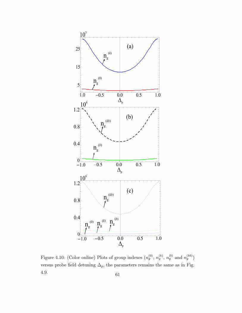
Figure 4.10: (Color online) Plots of group indexes (n(0)g , n
(k)g , n
(b)g and n
(kb)g )
versus probe field detuning ∆p, the parameters remains the same as in Fig.
4.9. 61

[68, 149]. It will be more constructive to study the control of group velocity
inside the medium by incorporating the combined effect of Kerr nonlinearity
and Doppler broadening. Now we incorporate the combined effect of Kerr
nonlinearity and Doppler broadening and study the group velocity inside the
medium which is the major part of this work. We are expecting more and
more slow group velocity inside the medium via combined effect of Kerr non-
linearity and Doppler broadening. We use Eq. (4.17) and plot the real part
of susceptibility χ(kb) versus probe field detuning for Ω2 = 3γ, see Fig. 4.9(b).
For the combined effect of Kerr nonlinearity and Doppler broadening we in-
vestigate a very steep normal dispersion that leads to more and more slow
group velocity inside the medium. In Fig. 4.9(c), we plot all the real parts of
susceptibilities versus probe field detuning, from this plot we conclude that
the slope of normal dispersion for Re[χ(kb)] is very steep as compare to the
slopes of χ(0), χ(k) and χ(b).
There is a strong correlation between dispersion and group index of the
medium i.e., the group index increases with increase the dispersion of the
medium and vice versa. In the above analysis we show the enhancement
of normal dispersion using Kerr nonlinearity and Doppler broadening effect.
The group index also change with changing the dispersion of the medium,
so we plot n(0)g , n
(k)g , n
(b)g and n
(kb)g versus probe field detuning, see Fig. 4.10.
Due to the combined effect of Kerr nonlinearity and Doppler broadening we
notice that the group index n(kb)g is very large as compare to n
(0)g , n
(k)g and
n(b)g .
Now to study the behavior of group index of the atomic medium for
different choices of the intensity of Kerr field , we plot the group index n(k)g
and n(kb)g versus Kerr field Ω2. In Fig. 4.11(a), the plot shows the group
index n(k)g versus Kerr field, here we notice that the group index of the atomic
62

Figure 4.11: (Color online) Plots of group index n(k)g and n
(kb)g versus Kerr
field Ω2 at ∆p = 0, (a) without Doppler broadening effect (b) with Doppler
broadening effect, the remaining parameters remains the same as in Fig. 4.9
63

medium becomes more positive for the normal dispersion with an increase
in the strength of the Kerr field. In Fig. 4.11(b) we plot the group index
n(kb)g versus Kerr field and investigate similar behavior as we observed in Fig.
4.11(a). The group index n(kb)g of the atomic medium is more positive as
compare to the group index n(b)g , because in n
(kb)g both the Kerr and Doppler
broadening effects are now involve.
In this section, we have discussed the control over the optical properties
of the medium via Kerr nonlinearity and Doppler Broadening effect. In
the coming section, we have a plan to explore the control over the optical
properties of the EIT N-type medium in the presence of both Kerr field and
SGC effect.
4.3 Control of Group Velocity via Sponta-
neous Generated Coherence and Kerr Non-
linearity
4.3.1 Introduction
We have discussed earlier, the control over light pulse propagation through
various atomic media via Kerr nonlinearity and Doppler broadening. In
this section we study the control over light pulse propagation through the
medium in the presence of both Kerr and SGC effect. Spontaneous emission
usually minimize the coherence in the system while SGC is an extra control
parameter, which enhances the coherence in the system and plays a useful
role in many optical process. The enhancing Kerr nonlinearity via SGC is
reported in 2006 [73]. SGC depends on quantum interference of spontaneous
emissions between two channels. The quantum interference effect has been
64

noticed earlier in three-level Λ-type system, where the spontaneous emission
interfere from a single excited state to two lower closely spaced levels [119].
Similarly, in V-type atomic system the spontaneous emission interfere from
two closely spaced upper levels to a common ground state [120]. Actually, this
coherence based on nonorthogonality of the two transition dipole moments.
More recently, The control of group velocity has been noticed in different
atomic media via a Kerr field [151, 152, 153]. In their work, it has been
noticed that a Kerr nonlinearity enhanced the group index of the medium,
which leads to slow group velocity inside the medium. Now it will be more
constructive to study the control of group velocity using the collective effect
of SGC and Kerr field.
In this section, we study the light pulse propagation inside a medium
via Kerr nonlinearity and SGC. Each atom of a medium consist of N -type
atomic configuration of 85Rb atoms. A Kerr field enhance the group index
which leads to slow group velocity as noticed earlier [139, 151, 152, 153]. We
also investigate the individual effect of SGC on group velocity. The important
and major part of this article is to study the control of group velocity via
the collective effect of SGC and Kerr field.
4.3.2 Model
The energy-level configuration of the atom-field interaction are presented in
Fig. 4.12. We consider a realistic four-level N -type atomic system of rubid-
ium atoms (85Rb) each having energy levels |a〉, |b〉, |c〉 and |d〉. An intense
driving laser field E1 is applied between level |a〉 and |b〉 with corresponding
Rabi frequency Ω1. Similarly, a weak probe field Ep and a strong Kerr field
Ek are applied between |b〉 → |c〉 and |c〉 → |d〉 with corresponding Rabi fre-
quency Ωp and Ωk, respectively. Here, γ1 and γ2 are the spontaneous decay
65

Figure 4.12: (Color online) (a) Schematics of the four-level N -type rubidium
atomic system (b) dipole moments of driving and probe fields.
rates of the excited level |b〉 to the ground levels |a〉 and |c〉. For generation
of SGC the two lower levels |a〉 and |c〉 must be closely spaced, it is due to
the fact that the two transitions of the excited state interact with the same
vacuum mode.
The interaction picture Hamiltonian for system in rotating wave and
dipole approximation is given by
V = −~[(∆1 −∆p)|c〉〈c|+ ∆1|b〉〈b|+ (∆1 −∆p + ∆k)
|d〉〈d|+ Ω1|a〉〈b|+ Ωp|c〉〈b|+ Ωk|c〉〈d|], (4.19)
where ∆p, ∆1 and ∆k are the corresponding probe and driving field de-
tunings, respectively. We consider that the driving laser field E1 and Ek are
strong fields while the probe field Ep is a weak field which means |Ω1|and|Ωk| >>
66

|Ωp|. Now the corresponding rate equations can be written as
ρbc = [i∆p − γ1 − γ2]ρbc + iΩ1ρac + iΩp(ρcc − ρbb)
−iΩkρbd,
ρac = [−i(∆1 −∆p)− Γ1]ρac + iΩ1ρbc − iΩpρab
−iΩkρad + 2q√γ1γ2ρbb,
ρbd = i(∆p −∆k)ρbd + iΩ1ρad + iΩpρcd
−iΩkρbc,
ρad = [−i(∆1 −∆p + ∆k)− γ2]ρad + iΩ1ρbd
−iΩ2ρac,
ρbb = (−γ1 − γ2)ρbb + iΩ1ρab − iΩ1ρba,
ρab = (−i∆1 − γ1)ρab + iΩ1ρbb,
ρba = (i∆1 − γ1)ρba − iΩ1ρbb,
(4.20)
where γ1, γ2 and γ3 are the decay rates as shown in Fig.4.12 whereas Γ is the
forbidden decay rate between level |a〉 and |c〉.Here, the parameter q denotes the alignment of two dipole moments ~µba
and ~µbc. For the orientations of the atomic dipole moments ~µba and ~µbc the
effect of SGC is very sensitive. The parameter q may further be defined as
q = ~µba.~µbc/ |~µba.~µbc| = cosθ arises due to the quantum interference between
two decay channels |b〉 → |a〉 and |b〉 → |c〉, whereas θ is the angle between the
two dipole moments. The term q√γ1γ2 represents the quantum interference
resulting from the cross coupling between the spontaneous emission channels
|b〉 → |a〉 and |b〉 → |c〉. In fact, the parameter q represents the strength
of the interference in spontaneous emission. If the two dipole moments are
orthogonal to each other then q = 0, which clearly shows that there is no
67

quantum interference due to spontaneous emission. When the two dipole
moments are parallel to each other then the quantum interference is maximal
and q = 1. The control of alignment of two dipole moments depends on the
angle θ between them. The angle θ may be adjusted with the help of external
driving (E1) and probe (Ep) fields, see Fig. 4.12(b). It is due to the fact
that the probe and control fields do not interact with each other’s transitions
so that one must be perpendicular to the dipole moment coupled to the
other [121]. So the quantum interference effect can be adjusted by control
the alignments of two dipole moments. The driving (Ω1) and probe (Ωp)
fields associated to the angle θ and therefore we can write as Ω1 = Ω01sinθ =
Ω01
√
1− q2.
The polarization P of the medium depends on the electric field Ep and
can be calculated as:
P = χε0Ep; (4.21)
where P = 2Nµbcρbc and Ep = Ωp~/µcb. After simplification the expression
for the dielectric susceptibility χ for the given atom-field system as shown in
Fig. 4.12 can be written as
χ =2N |µbc|2~ε0Ωp
ρbc, (4.22)
where N represent density of the atomic medium while µbc and ρbc are the
dipole and off-diagonal matrices elements, respectively, for the corresponding
optical transition. It is clear form Eq. (4.22) that we should first find the
density matrix element ρbc. it can be obtain by considering weak probe field
approximation. we can take the probe field in the first order while the control
and kerr fields in all orders. Following weak field approximation we presume
that driving (E1) and control (Ek) fields are significantly stronger then probe
field ( Ep), which means that |Ωp| is much weaker then |Ω1| and |Ωk|. Here,
68

the zeroth-order solution of the probe field elements are equal to zero except
ρ0cc = 1, it is due to the fact that the atom are initially prepared in the
ground state |c〉. The above Eq. (4.20) can be solved easily following the
recipe discussed in the Appendix 2 to get ρbc with resonance condition i.e.,
∆1 = ∆k = 0
ρbc =[(iΓ + ∆p)(iγ3∆p + ∆2
p − Ω21)−∆pΩ
2k]Ωp
B, (4.23)
where
B = γ2γ3∆2p − iγ2∆
3p − iγ3∆
3p −∆4
p + iγ2∆pΩ21
+iγ3∆pΩ21 + 2∆2
pΩ21 − Ω4
1 + [iγ2∆p + iγ3∆p
+2(∆2p + Ω2
1)]Ω2k − Ω4
k + Γ[(γ1 + γ2 − i∆p)
(iγ3∆p + ∆2p − Ω2
1)− (γ3 − i∆p)Ω2k]
+γ1∆p[γ3∆p − i(∆2p − Ω2
1 − Ω2k)]. (4.24)
Using Eq. (4.22) and (4.23) we can write the optical susceptibility for the
atom-field interaction can be written as
χ = β(iΓ + ∆p)(iγ3∆p + ∆2
p − Ω21)−∆pΩ
2k
B, (4.25)
where β=2N |µbc|2
~ε0.
We consider Ωk is a Kerr field, then the effect of Kerr field Ωk on the
susceptibility can be studied by the following expression [139, 151, 152, 153].
χ(k) = χ(0) + Ω2kχ
(1), (4.26)
where χ(0) is the susceptibility of the medium without Kerr nonlinearity
and can be calculated as
69

χ(0) = − (Γ− i∆p)
γ1∆p + γ2∆p − i∆2p + Γ(iγ1 + iγ2 + ∆p) + iΩ2
1
.
(4.27)
The second part in Eq. (4.26) shows the nonlinear part of the suscepti-
bility via Kerr field Ωk, where χ(1) can be calculated as
χ(1) =∂χ
∂Ω2k
∣
∣
∣
∣
Ωk=0
(4.28)
χ(1) =Γ2(iγ3 + ∆p)−∆p(iγ3∆p + ∆2
p + 3Ω21) + 2Γ(γ3∆p − i(∆2
p + Ω21))
(iγ3∆p + ∆2p − Ω2
1)[Γ(γ1 + γ2 − i∆p)− iγ1∆p − iγ2∆p −∆2p + Ω2
1]2.
(4.29)
The group index of the medium in the presence of Kerr Field can be
calculated using the expression given in Eq. (4.8).
4.3.3 Results presentation
The enhancement of group index of a medium has been studied earlier [139,
151, 152, 153] via strength of Kerr nonlinearity. The enhancement of group
index of a medium then leads to slow group velocity inside the medium.
In the following we start our discussion by studying the control of group
velocity via Kerr nonlinearity and SGC when a light pulse is propagating
inside a medium. Initially, we study the control of group velocity inside a
medium via SGC and then by Kerr nonlinearity. Further, we consider the
collective effect of SGC and Kerr field on group velocity in four-level N -type
system. We also consider that the atoms are initially prepared in level |c〉and the corresponding parameters are γ = 1MHz, γ1 = γ2 = γ3 = 1γ,
Γ = 0.002γ, Ω01 = 4γ and νp = 1000γ.
70

We investigate the effect of SGC on group velocity when a light pulse is
propagating inside a medium. We study the group velocity in the absence
of Kerr field i.e., Ωk = 0, then the system becomes a simple three-level
Λ-configuration. In Fig. 4.13(a) we plot the real and imaginary parts of
susceptibility χ(0) versus probe field detuning without considering SGC i.e.,
q = 0. The plot shows a normal dispersion (subluminal behavior) which has
been noticed earlier for EIT process [49, 148]. In this plot we consider q = 0,
which means that there is no quantum interference between spontaneous
emission channels. We also plot the group index versus probe field detuning
and at resonance condition we calculate the group index n(0)g = 393. Next,
we increase the value of q from 0 to 0.99 and again we plot the susceptibility
χ(0) and group index n(0)g versus probe field detuning, see Fig. 4.14. A strong
quantum interference effect of the spontaneous emission channels occurs for
the maximum value of q. In this time we get a steep dispersion along with
narrow EIT window as shown in 4.14(a) which has been noticed earlier [73,
121]. As EIT window depends on stark splitting which is directly related to
the control or driving field. When the strength of the control field increases
the width of EIT window also increases and vice versa. Now it is obvious
from the relation Ω1 = Ω01
√
1− q2 that q can affect the control field Ω1.
If the value of q increases the control field decreases and the EIT window
also decreases. So at high value i.e, q = 0.99 the width of the EIT window
decreases. For the maximum value of q we also study the group index of the
medium and at resonance condition and calculate n(0)g = 20× 103.
Now we switch on a Kerr field Ωk and investigate the light pulse prop-
agation inside the medium. We consider initially the value of q = 0 which
shows that there is no quantum interference effect of the spontaneous emis-
sion channels. We plot the susceptibility χ(k) and group index n(k)g using
71

Figure 4.13: (Color online) Plots of (a) real (solid) and imaginary (dashed)
parts of the susceptibility χ(0) (b) group index n(0)g versus probe field detuning
∆p for q = 0, γ = 1MHz, γ1 = γ2 = γ3 = 1γ, Γ = 0.002γ,Ω01 = 4γ, and
νp = 1000γ.
72
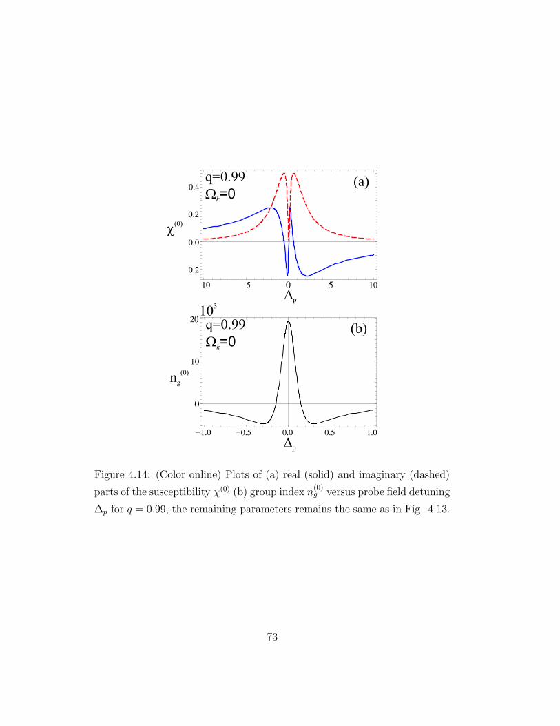
Figure 4.14: (Color online) Plots of (a) real (solid) and imaginary (dashed)
parts of the susceptibility χ(0) (b) group index n(0)g versus probe field detuning
∆p for q = 0.99, the remaining parameters remains the same as in Fig. 4.13.
73

Figure 4.15: (Color online) Plots of (a) real (solid) and imaginary (dashed)
parts of the susceptibility χ(k) (b) group index n(k)g versus probe field detuning
∆p for q = 0 and Ωk = 2γ, the remaining parameters remains the same as in
Fig. 4.13.
74

Figure 4.16: (Color online) Plots of (a) real (solid) and imaginary (dashed)
parts of the susceptibility χ(k) (b) group index n(k)g versus probe field detuning
∆p for q = 0.99 and Ωk = 2γ, the remaining parameters remains the same as
in Fig. 4.13.
75
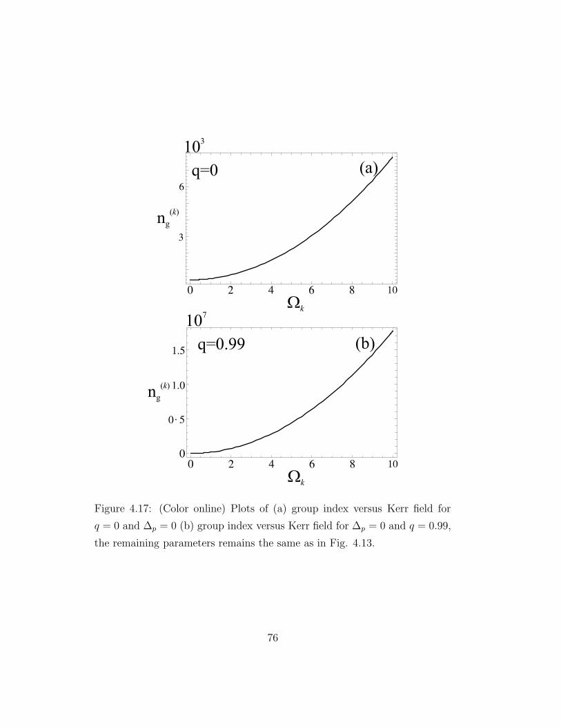
Figure 4.17: (Color online) Plots of (a) group index versus Kerr field for
q = 0 and ∆p = 0 (b) group index versus Kerr field for ∆p = 0 and q = 0.99,
the remaining parameters remains the same as in Fig. 4.13.
76

Eqs. (4.26) and (4.8), respectively. The dispersion as well as the group in-
dex increases with increasing the Kerr field, see Fig. 4.15. We consider the
Kerr field Ωk = 2γ and calculate the group index at resonance condition
i.e., n(k)g = 687. This clearly tells us that the Kerr field enhance the group
index which leads to slow group velocity. Similar effect of Kerr field on the
dispersion and group index has been investigated earlier in four-level N -type
atomic medium [151].
Further, it will be more appropriate to study the collective effect of SGC
and Kerr field on control of group velocity. As discussed previously that the
individual effect of SGC and Kerr field control the group velocity when a light
pulse is propagating inside the medium. In our proposed atomic configuration
both SGC and Kerr field are present then it is more constructive to study the
collective effect of these phenomenon on the slow light propagation. We are
expecting a more slow group velocity inside a medium as compared to the
individual effect of SGC and Kerr field. We consider that there is a strong
quantum interference effect i.e., q = 0.99 and the Kerr field Ωk = 2γ. We
plot the real and imaginary parts of susceptibility χ(k) and group index n(k)g
versus probe field detuning, see Fig. 4.16. Due to the collective effect of SGC
and Kerr field the normal dispersion (solid curve) becomes more and more
steep as compared to the individual effect, see Fig. 4.16(a). We also plot the
group index as shown in Fig. 4.16(b), at resonance condition we calculate
the group index i.e., n(k)g = 7× 10⁵. This enhancement of group index then
leads to more slow group velocity inside the medium.
To study the enhancement of group index of the medium with increasing
the strength of the Kerr filed Ωk, we plot the group index n(k)g versus strength
of the Kerr field. In Fig. 4.17(a), the plot shows the group index n(k)g versus
strength of a Kerr field by considering no quantum interference effect present
77

i.e., q = 0, here we notice that the group index of the atomic medium becomes
more positive for the normal dispersion with an increase in the strength of
a Kerr field. Next, we consider a strong quantum interference effect in our
system i.e., q = 0.99 and plot the group index n(k)g of the medium versus the
strength of Kerr field and investigate similar behavior as we examined earlier
(in Fig. 4.17(a)), see Fig. 4.17(b). But at this time the group index becomes
more and more positive via the collective effect of SGC and Kerr field. Now
It is clear that by increasing the intensity of the Kerr nonlinear field we can
obtain much slower pulse propagation inside the medium. Obviously halted
or stopped pulses can be achieved via Kerr Field.
The slow light have potential applications, these include for example, slow
light devices are considered for enhancing other optical nonlinearities [154].
Slowing or stopping light is also used to achieve the long storage times to
perform quantum operations [17, 58]. Slow light could be used to enhance
the sensitivity of spectral interferometer which has been noticed by Shi and
co-workers in 2007 [155]. Similarly, slow light has been used in laboratory
settings to achieve true time delay to synchronize the radio frequency emitters
of a phased-array radar system [156, 157].
In this section, we have studied the influence of Kerr field and SGC effect
on the propagation of light pulse through N-type atomic medium. In the
forthcoming section, we have a scheme to study the effect of two Kerr fields
by considering tripod atomic medium.
78

4.4 Control of Group Velocity via Double Kerr
Nonlinearity in Four-Level Tripod Atomic
System
4.4.1 Introduction
In the last sections, we presented a detail study on the behavior of light prop-
agation via Kerr field, Doppler broadening and SGC effect through various
atomic media. The Kerr non-linearity, Doppler broadening and SGC affect
the light pulse propagation through the medium, which leads to slow group
velocity. To attain a more slow group velocity inside the medium, next we
consider two Kerr fields in a single atomic configuration of tripod atomic sys-
tem. In this section, we theoretically investigate the behavior of light pulse
propagation inside a medium consist of four-level tripod atomic configura-
tion. Each atom of a four-level tripod atomic medium consist of D1 line of
87Rb. A single Kerr field enhance the group index which leads to control of
group velocity as noticed earlier [139, 151, 152, 153]. Here, in this section
we expect a strong control of group velocity via double Kerr nonlinear fields
inside a four-level tripod atomic medium. The motivation comes from an
earlier experimental work where four-level tripod atomic medium has been
used to obtain large cross-phase modulation in a cold D1 line of rubidium
(87Rb) medium without implying high magnetic field [158]. In the article
[158] a trigger, probe and pump fields are considered. We follow the same
experimental model and consider trigger and pump fields as Kerr nonlinear
and investigate the control of group velocity via double Kerr nonlinear fields.
The control of group velocity using double Kerr fields then leads to more and
more slow group velocity inside the medium.
79

Figure 4.18: (Color online) Schematics of the D1 line in the rubidium (87Rb)
four-level tripod atomic system
4.4.2 Model
The schematics of the atom field interaction are presented in Fig.4.18. We
suggest an experimental model of four-level tripod atomic system [158] each
having energy level |1〉, |2〉, |3〉 and |4〉. Two intense driving laser fields Ek1
and Ek2 are applied between level |2〉 ↔ |4〉 and |3〉 ↔ |4〉 with corresponding
Rabi frequencies Ωk1 and Ωk2, respectively. Similarly, a weak probe field Ep
between |4〉 ↔ |1〉 is applied with corresponding Rabi frequency Ωp.
The interaction picture Hamiltonian for the system in rotating wave and
dipole approximation is given by
V = −~(Ωpe−i∆pt|4〉〈1|+ Ωk1e
−i∆k1t|4〉〈2|
+Ωk2e−i∆k2t|4〉〈3|+ cc), (4.30)
80

where ∆p, ∆k1 and ∆k2 are the corresponding probe and driving field detun-
ings, respectively. We consider that the driving laser field Ek1 and Ek2 are
strong fields while the probe field Ep is a weak field which means |Ωk1|and|Ωk2| >>|Ωp|. Now the corresponding rate equations can be written as
ρ41 = [i∆p − γ41]ρ41 + iΩp(ρ11 − ρ44) + iΩk1ρ21
+iΩk2ρ31,
ρ21 = [i(∆p −∆k1)− γ21]ρ21 + iΩk1ρ41 − iΩpρ24,
ρ31 = [i(∆p −∆k2)− γ31]ρ31 + iΩk2ρ41 − iΩpρ34,
ρ24 = [−i∆k1 − γ24]ρ24 + iΩk1(ρ44 − ρ22)− iΩpρ21
−iΩk2ρ23,
ρ34 = [−i∆k2 − γ34]ρ34 + iΩk2(ρ44 − ρ33)− iΩk1ρ32
−iΩpρ31,
ρ23 = [−i(∆k1 −∆k2)− γ23]ρ23 + iΩk1ρ43 − iΩk2ρ24.
(4.31)
where γ21, γ31 and γ41 are the decay rates from level |2〉, |3〉 and |4〉 to |1〉,respectively.
ρ41 can be calculated from the coupled rate equations given in Eq. (4.31)
using some approximations. Following the weak probe approximation, the
susceptibility of the medium can be obtain as:
χ = βi(γ21 + i∆k1 − i∆p)(γ31 + i∆k2 − i∆p)
B, (4.32)
where β=N |℘41|2
ε0~with N be the atomic density, ℘41 is the dipole matrix
element and B is given as:
B = [γ31 − i(−∆k2 + ∆p)][(γ21 + i∆k1 − i∆p)(γ41 − i∆p) + Ω2k1]
−iΩk2(iγ21Ωk2 −∆k1Ωk2 + ∆pΩk2), (4.33)
81

Here, we consider Ωk1 is a Kerr field while Ωk2 has no Kerr nonlinearity,
then the effect of Kerr field Ωk1 on the susceptibility can be studied by the
following expression [139, 151, 152, 153]
χ(k1) = χ(0) + Ω2k1
∂χ
∂Ω2k1
∣
∣
∣
∣
Ωk1=0
, (4.34)
where χ(0) is the optical susceptibility of the medium in the absence of Kerr
field, i.e., Ωk1 = 0. The second part in Eq. (4.34) gives the nonlinear behavior
of the optical susceptibility via Kerr field Ωk1. Now the group index of the
medium which is defined as n(k1)g = c/vg where c and vg be the speed of light
and the group velocity, respectively, can therefore be calculated using the
expression
n(k1)g = 1 + 2πRe[χ(k1)] + 2πνpRe[
∂χ(k1)
∂∆p], (4.35)
where νp is the frequency of the probe field.
Similarly, by considering Ωk2 is a Kerr field while Ωk1 has no Kerr nonlin-
earity, the effect of Kerr field Ωk2 on the susceptibility and group index can
be studied as
χ(k2) = χ(0) + Ω2k2
∂χ
∂Ω2k2
∣
∣
∣
∣
Ωk2=0
, (4.36)
and
n(k2)g = 1 + 2πRe[χ(k2)] + 2πνpRe[
∂χ(k2)
∂∆p], (4.37)
respectively.
When both Ωk1 and Ωk2 are considered as Kerr fields, which having same
strength equal to Ωk i.e., Ωk = Ωk1 = Ωk2 , then the collective effect of the
Kerr fields on the susceptibility and group index can be studied as
χ(k1k2) = χ(0) + Ω2k
∂χ
∂Ω2k
∣
∣
∣
∣
Ωk=0
, (4.38)
and
n(k1k2)g = 1 + 2πRe[χ(k1k2)] + 2πνpRe[
∂χ(k1k2)
∂∆p], (4.39)
82

respectively.
4.4.3 Results presentation
We know from an earlier study [139, 151, 152, 153] that the group index of a
medium increases via increasing the strength of a Kerr field. The enhance-
ment of group index then leads to slow group velocity inside the medium. A
single Kerr field is used to control the group velocity in the above study. In
the following we start our discussion by studying the control of group velocity
via Kerr nonlinearity when a light pulse is propagating inside a four-level tri-
pod atomic medium. We suggest an experimental model consist of four-level
tripod atomic medium with initial atomic state in the D1 line of 87Rb atom.
Initially, we study the control of group velocity inside a medium via a single
Kerr field. Then we consider double Kerr field in four-level tripod atomic
medium and study the control of group velocity. We also consider that the
atoms are initially prepared in level |1〉 and the corresponding parameters
are γ41 = 0.1γ, γ = 1MHz, ∆k1 = ∆k2 = 0, γ31 = γ21 = 1γ, and νp = 1000γ.
4.4.4 Control of Group Velocity via a Single Kerr Field
We study the effect of a single Kerr field on the group velocity when a light
pulse is propagating inside the medium. We consider that Ωk1 is a Kerr field
while Ωk2 = 1γ which has no Kerr nonlinearity. We use Eq.(4.34) and plot the
real and imaginary parts of the optical susceptibility χ(k1) where as the group
index of the medium is plotted using Eq. (4.35). Fig. (4.19)(a) presents real
and imaginary parts of the susceptibility χ(k1) versus probe field detuning
∆p for Ωk1 = 0.5γ. At resonance or round about resonance condition the
real part of the susceptibility gives the dispersion (normal) property while
the imaginary part gives the absorption property. We plot the group index
83
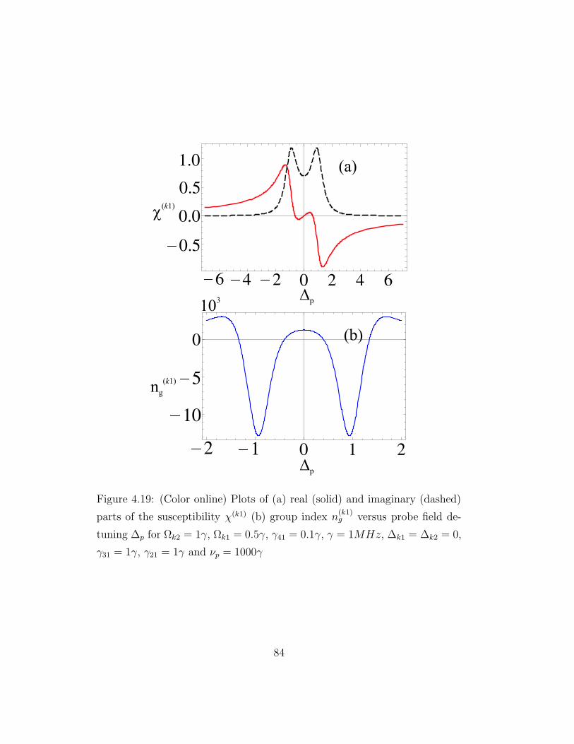
Figure 4.19: (Color online) Plots of (a) real (solid) and imaginary (dashed)
parts of the susceptibility χ(k1) (b) group index n(k1)g versus probe field de-
tuning ∆p for Ωk2 = 1γ, Ωk1 = 0.5γ, γ41 = 0.1γ, γ = 1MHz, ∆k1 = ∆k2 = 0,
γ31 = 1γ, γ21 = 1γ and νp = 1000γ
84

n(k1)g versus probe field detuning ∆p for the same parameters and calculate
the group index n(k1)g = 1299 of the medium at resonance condition ∆p = 0.
Next, we slightly change the Kerr field Ωk1 from 0.5γ to 1γ and remain all
the other parameters unchanged. We again plot the susceptibility χ(k1) and
the group index n(k1)g versus probe field detuning. We calculate the group
index again at resonance condition, the group index increases from 1299 to
5193 with increasing the Kerr field from 0.5γ to 1γ. We notice that the group
index increases approximately four times when the strength of the Kerr field
increases from 0.5γ to 1γ.
Now we study the control of group velocity inside the medium by con-
sidering Ωk2 is a Kerr field. The other field Ωk1 = 1γ which has no Kerr
nonlinearity while all other parameters remain unchanged. To investigate
the effect on group velocity via Kerr field Ωk2, we use Eq. (4.36) and Eq.
(4.37) for susceptibility and group index of the medium, respectively. We no-
tice that the susceptibility and group index remains the same as we observed
above for the case of Kerr field Ωk1.
4.4.5 Control of Group Velocity via Double Kerr Fields
The control of group velocity using a single Kerr field have been studied
earlier in different atomic media [139, 151, 152, 153]. We study the control
of group velocity via a single Kerr field using an experimental model of D1
line of 87Rb atom. We also study the individual effect of two Kerr fields Ωk1
and Ωk2 on group velocity inside a four-level atomic medium. Now it will
be more constructive to investigate the collective effect of two Kerr fields on
the control of group velocity inside a medium. Initially, we consider that the
two Kerr fields are zero, the second and third part of Eq. (4.38) vanishes
and then χ(k1k2) = χ(0). The four-level atomic system reduces to a simple
85

Figure 4.20: (Color online) Plots of (a) real (solid) and imaginary (dashed)
parts of the susceptibility χ(k1) (b) group index n(k1)g versus probe field de-
tuning ∆p for Ωk1 = 1γ, the remaining parameters remains the same as in
Fig. 4.19
86

Figure 4.21: (Color online) Plots of (a) real (solid) and imaginary (dashed)
parts of the susceptibility χ(k1k2) (b) group index n(k1k2)g versus probe field
detuning ∆p for Ωk1 = Ωk2 = 0, the remaining parameters remains the same
as in Fig. 4.19.
87

two-level and becomes an absorptive medium. We plot the susceptibility
χ(k1k2) and group index n(k1k2)g versus probe field detuning, see Fig. (2.21).
We observe a high absorption along with anomalous dispersion and negative
group velocity that leads to fast light propagation inside the medium. The
dispersion change dramatically from anomalous to normal when the two Kerr
fields is switched on simultaneously. The normal dispersion then leads to slow
group velocity inside the medium. Here, we also notice that the medium
turns into an amplifier exhibiting slow pulse propagation inside the medium.
The normal dispersion that we notice here is very steep by just considering
the two Kerr fields Ωk1 = Ωk1 = 1γ, see Fig. (4.22)(a). Further, we study
the group index of the medium for the same parameters and observe a very
high group index at resonance condition, see Fig.(4.22)(b). We investigate
a very strong control of the group velocity via collective effect of two Kerr
fields. In section A, we observed the group index at resonance condition i.e.,
n(k1)g = 5193 for a Kerr field Ωk1 = 1γ. The collective effect of two Kerr
fields enhance the group index to 2.5× 10⁷ by considering Ωk1 = Ωk2 = 1γ.
The collective effect of two Kerr fields enhance the group index more than
4814 times as compare to a single Kerr field. To study the enhancement
of group index of the medium with increasing the strength of the Kerr filed
Ωk1, we plot the group index n(k1)g versus strength of single Kerr field. In Fig.
(4.23)(a), the plot shows the group index n(k1)g versus strength of single Kerr
field, here we notice that the group index of the atomic medium becomes
more positive for the normal dispersion with an increase in the strength of
a Kerr field. Next, we consider Ωk1 = Ωk2 and plot the group index n(k1k2)g
of the medium versus the strengths of two Kerr fields and investigate similar
behavior as we observed earlier (in Fig. 4.23(a)), see Fig. 4.23(b). But at
this time the group index becomes more and more positive via the collective
88

Figure 4.22: (Color online) Plots of (a) real (solid) and imaginary (dashed)
parts of the susceptibility χ(k1k2) (b) group index n(k1k2)g versus probe field
detuning ∆p for Ωk1 = Ωk2 = 1γ, the remaining parameters remains the same
as in Fig. 4.19.
89

effect of two Kerr fields.
In our proposed atomic system there is a strong control of the group
velocity via external Kerr fields. The light pulse can be slow down even
that one can stop the light pulse and store it as per their requirement. We
give a theoretical idea using a four-level experimental system of D1 line of
87Rb atoms. For the Kerr fields Ωk1 = Ωk2 = 10γ we notice that the group
velocity inside the medium reduces to vg = c/(2.5×109) = 0.12m/s, see Fig.
4.23(b). With increasing the strength of the Kerr fields the group velocity
decreases further. The slow light have potential applications, these include
for example, slow light devices are considered for enhancing other optical
nonlinearities [154]. Slowing or stopping light is also used to achieve the
long storage times to perform quantum operations [58, 17]. Slow light could
be used to enhance the sensitivity of spectral interferometer which has been
noticed by Shi and co-workers in 2007 [155]. similarly, slow light has been
used in laboratory settings to achieve true time delay to synchronize the
radio frequency emitters of a phased-array radar system [156, 157].
90

Figure 4.23: (Color online) Plots of group index n(k1)g versus (a) single Kerr
field when Ωk2 = 1γ and∆p = 0 (b) and n(k1k2)g versus double Kerr fields, the
remaining parameters are the same as in Fig. 4.19.
91
Chapter 5
Conclusions
In conclusion, we considered different atomic media and study the influence
of Kerr non-linearity, Doppler broadening and SGC on light pulse propaga-
tion. We theoretically investigated that the group velocity of light pulse is
reduced via Kerr non-linearity, Doppler broadening and SGC. The reduced
group velocity of light pulse then leads to slow light inside the medium. For
four-level N -type atomic medium we studied the influence of relaxation rate
of forbidden transition and Kerr non-linearity on light pulse propagation in-
side the medium. It is found that the relaxation rate of forbidden transition
change the behavior of light pulse propagation through the medium. The
group velocity change from positive to negative via changing the relaxation
rate of forbidden transition (Γ). In the same atomic medium we also studied
the the influence of Kerr non-linearity on light pulse propagation. The posi-
tive as well as negative group index increased via increasing the strength of
Kerr field. At Ωk = 10γ the group indeces are 5 × 10⁴ and −1.6 × 10⁵ for
normal and anomalous dispersion, respectively. It is found that the group
index for normal and anomalous dispersions can be increased via increasing
the strength of Kerr field. The increase of group index clearly shows that
by increasing the strength of Kerr field a more slow group velocity can be
92

achieved.
Next, we considered a four-level lambda-type configuration of 87Rb atoms
and study the weak pulse propagation inside the medium. As previously in-
vestigated that the Kerr field influenced the group index of the medium. In
the present scheme we incorporated the Kerr as well as the Doppler broaden-
ing to monitor the light pulse propagation through the medium. we expected
control over the group index of an EIT process via a Kerr field and Doppler
broadening which leads to a slower group velocity inside the medium. Ini-
tially, we studied the influence of Kerr field and Doppler broadening on light
pulse propagation through the medium separately. It is found that the group
index increased via Kerr field as well as by Doppler broadening. To achieve
a more slow group velocity inside the medium next we considered both the
Kerr field and Doppler broadening and studied the behavior of light pulse
propagation through the medium. To see a more clear picture of light pulse
propagation inside the medium when both Kerr field and Doppler broaden-
ing are considered. The behavior of group index of the medium for different
choices of intensity of Kerr field is plotted for two cases i.e., without Doppler
broadening and with Doppler broadening. We noticed that the group index
is 1.2 × 10⁶ at Ωk = 10γ when there is no Doppler broadening. The group
index increased from 1.2 × 10⁶ to 4.7 × 10⁷ at Ωk = 10γ for the case when
Doppler broadening is considered. This clearly shows that the group velocity
decreases more with including both Kerr field and Doppler broadening.
As discussed earlier, that Kerr field and Doppler broadening affects the
group velocity of light through the medium. In the present scheme we stud-
ied the influence of the Kerr field along with SGC on the propagation of light
pulse through N -type atomic medium. The Kerr field enhances the group
index of the medium, which leads to slow group velocity. The separate effect
93

of SGC on the propagation of light pulse bring an appreciable change to the
transparency window. The narrow transparency window is found with in-
creasing SGC parameter. The SGC increases the group index of the medium
and we have observed 20×103 for maximum SGC. To attain more slow group
velocity, we incorporated both Kerr and SGC effects inside the medium. It is
found that the group index increase Via Kerr field along with SGC, which re-
sulted the slow group velocity through the medium. To inestigate more clear
picture of the propagation of light pulse through the medium, we plotted the
group index with Kerr field for two cases i.e., without SGC and with SGC.
The value of group index at Ωk = 10γ is found to be 8×10³, when there is no
SGC effect involve in the medium. The value of group index increased from
8 × 10³ to 1.8 × 10⁷ at Ωk = 10γ, when SGC effect in the medium is taken
into account. It clearly shows that an ultra-slow group velocity can be found
by incorporating both Kerr field and SGC simultaneously in the medium.
Next, we considered an experimental model consist of four-level tripod-
configuration with initial atomic state in the D1 line of 87Rb atom and mon-
itor the propagation of weak pulse through the medium. Previously, we
discussed the light pulse propagation via Kerr field, Doppler broadening and
SGC, which have reduced the group velocity of light through various atomic
medium. A strong control over light pulse propagation can be obtained by
considering two Kerr fields in a single atomic medium. The single Kerr field
also enhances the group index of the this medium as discussed earlier for the
other atomic medium. It is found that a high group index of the medium
can be observed by taking two Kerr fields of the same strength. To present a
clear picture over the control of light pulse propagation, we plotted the group
index of the medium with single and two Kerr fields of the same strength.
The value of the group index is found to be 4.7 × 10⁵ at Ωk1 or Ωk2 = 10γ.
94

The value of the group index of the medium increased from 4.7 × 10⁵ to
2.7 × 10⁹, when two Kerr Fields of the same strength i.e., Ωk1= Ωk2 = 10γ
are applied in the medium. The group velocity of light is reduced to 0.11
m/s in the presence of two Kerr fields. It clearly shows that the light pulse
can be halted or stopped by considering two Kerr fields in a single medium.
95

Appendices
96

Appendix1
B = Ω2k(4CD − Ω2
1 + Ω2k) + 16(γ3 + i∆1 − i∆p)(D(EC + Ω2
1/4) + 1/4EΩ2k)
+Ω21(4EC + F ).
Where
C = (γ1 + γ2 − i∆p),
D = (γ1 + γ2 + γ3 − i∆p),
E = (Γ + i∆1 − i∆p),
and
F = (Ω1 − Ω2)(Ω1 + Ω2).
97

Appendix2
Here, we consider the details of solving Eq. (4.20). We follow the same
method as has been used in [148, 159], saharai-four-level. We can write Eq.
(4.20) in the form as
R = −MR + C, (1)
where R, C and M are the column vectors and matrix, respectively, as given
below
R =(
ρbc ρac ρbd ρad ρbb ρab ρba
)T
,
C =(
iΩp 0 0 0 0 0 0)T
,
M =
−i∆p + γ1 + γ2 −iΩ1 iΩk 0 0 0 0
−iΩ1 i(∆1 − ∆p) + Γ 0 iΩk −2q√
γ1γ2 0 0
iΩk 0 −i(∆p − ∆k) −iΩ1 0 0 0
0 iΩk −iΩ1 i(∆1 − ∆p + ∆k) + γ3 0 0 0
0 0 0 0 γ1 + γ2 −iΩ1 iΩ1
0 0 0 0 −iΩ1 i∆1 + γ1 0
0 0 0 0 iΩ1 0 −i∆1 + γ1
.
Now the formal solution of such an equation can be written as
R(t) =
∫ t
−∞
e−M(t−t)Cdt = M−1C. (2)
We use Eq. 2 and get the solution for ρbc which is given in 4.23.
98

Bibliography
[1] L. I. Schiff, “Quantum Mechanics” McGraw-Hill Education, (1968).
[2] R. W. Boyd, “Nonlinear Optics” Academic Press, (2003).
[3] L. Allen and J.H. Eberly, “Optical Resonance and Two-Level Atoms”,
Dover Publications, 1987.
[4] W. Demtroder, “Laser Spectroscopy” Springer, (2002).
[5] M. Xiao, Y. q. Li, S. Z. Jin, J. G. Banacloche “Measurement of Disper-
sive Properties of Electromagnetically Induced Transparency in Rubid-
ium Atoms Phys. Rev. Lett. 74(5), 666-669 (1995).
[6] P. B. Sellin, G. A.Wilson, K. K. Meduri, T.W. Mossberg “Observation
of inversionless gain and field-assisted lasing in a nearly ideal three-level
cascade-type atomic system” Phys. Rev. A., 54(3), 2402-2407 (1996).
[7] Z. M. Zhu, D. J. Gauthier “Nearly transparent SBS slow light in an
optical fiber” Optics Express., 14(16), 7238-7245, (2006).
[8] M. O. Scully, S.-Y. Zhu, A. Gavrielides “Degenerate quantum-beat
laser: Lasing without inversion and inversion without lasing” Phys.
Rev. Lett. 62(24), 2813-2816 (1989).
99

[9] T. Baba, “Slow light in photonic crystals” Nat. Photon., 2(8),465-473
(2008).
[10] P. C. Ku, C.J. Chang-Hasnain, S.L. Chuang “Variable semiconductor
all-optical buffer” Electronics Letters., 38(24), 1581-1583 (2002).
[11] M. M. Kash, V. A. Sautenkov, A. S. Zibrov, L. Hollberg, G. R.
Welch, M. D. Lukin, Y. Rostovtsev, E. S. Fry, M. O. Scully “Ultra-
slow Group Velocity and Enhanced Nonlinear Optical Effects in a Co-
herently Driven Hot Atomic Gas” Phys. Rev. Lett. 82(26), 5229-5232
(1999).
[12] D. Budker, D. F. Kimball, S. M. Rochester, V. V. Yashchuk “Nonlinear
Magneto-optics and Reduced Group Velocity of Light in Atomic Vapor
with Slow Ground State Relaxation” Phys. Rev. Lett. 83(9), 1767-1770
(1999).
[13] R. M. Camacho, M. V. Pack, J. C. Howell “Low-distortion slow light
using two absorption resonances” Phys. Rev. A., 73(6), 063812(1-4)
(2006).
[14] S. E. Harris, J. E. Field, A. Kasapi “Dispersive properties of elec-
tromagnetically induced transparency” Phys. Rev. A., 46(1), R29-R32
(1992).
[15] A. Kasapi, M. Jain, G. Y. Yin, S. E. Harris “electromagnetically in-
duced transparency - propagation dynamics” Phys. Rev. Lett. 74(13),
2447-2450 (1995).
[16] L. Hau, S. Harris, Z. Dutton, C. Behroozi “Light speed reduction to
17 metres per second in an ultracold atomic gas” Nature., 397, 594-598
(1999).
100

[17] C. Liu, Z. Dutton, C. H. Behroozi, L. V. Hau “Observation of coherent
optical information storage in an atomic medium using halted light
pulses” Nature., 409(6819), 490-493 (2001).
[18] V. Boyer, C.F. McCormick, E. Arimondo, P. D. Lett “Ultraslow Prop-
agation of matched pulses by four-wave mixing in an atomic vapor”
arXiv., quant-ph/0703173 (2007).
[19] W. G. Yang, D. B. Conkey, B. Wu, D. L. Yin, A. R. Hawkins, H.
Schmidt “Atomic spectroscopy on a chip” Nature Photonics., 1(6), 331-
335 (2007).
[20] A. V. Turukhin, V. S. Sudarshanam, M. S. Shahriar, J. A. Musser, B.
S. Ham, P. R. Hemmer “Observation of Ultraslow and Stored Light
Pulses in a Solid” Phys. Rev. Lett. 88(2), 023602(1-4) (2001).
[21] M. S. Bigelow, N. N. Lepeshkin, R. W. Boyd “Observation of Ultraslow
Light Propagation in a Ruby Crystal at Room Temperature” Phys.
Rev. Lett. 90(11), 113903(1-4) (2003).
[22] M. S. Bigelow, N. N. Lepeshkin R. W. Boyd “Superluminal and Slow
Light Propagation in a Room-Temperature Solid” Science., 301(5630),
200-202 (2003).
[23] J. B. Khurgin “Optical buffers based on slow light in electromagnet-
ically induced transparent media and coupled resonator structures:
comparative analysis” J. Opt. Soc. Am. B. 22(5), 1062-1074 (2005).
[24] G. M. Gehring, A. Schweinsberg, C. Barsi, N. Kostinski, R. W. Boyd
“Observation of backward pulse propagation through a medium with
a negative group velocity” Science., 312(5775), 895-897 (2006).
101

[25] E. Shumakher, N. Orbach, A. Nevet, D. Dahan, G. Eisenstein “On
the balance between delay, bandwidth and signal distortion in slow
light systems based on stimulated Brillouin scattering in optical fibers”
Optics Express., 14(13), 5877-5884 (2006).
[26] Y. Okawachi, M. S. Bigelow, J. E. Sharping, Z. Zhu, A. Schweinsberg,
D. J. Gauthier, R. W. Boyd, A. L. Gaeta “Tunable All-Optical Delays
via Brillouin Slow Light in an Optical Fiber” Phys. Rev. Lett. 94(15),
153902(1-4) (2005).
[27] S. Residori, U. Bortolozzo, J. P. Huignard “Slow and Fast Light in
Liquid Crystal Light Valves” Phys. Rev. Lett. 100(20), 203603(1-4)
(2008).
[28] M. S. Shahriar, G. S. Pati, R. Tripathi, V. Gopal, M. Messall, K. Salit
“Ultrahigh enhancement in absolute and relative rotation sensing using
fast and slow light” Phys. Rev. A., 75(5), 053807(1-10) (2007).
[29] Z. Shi, R. W. Boyd, R. M. Camacho, P. K. Vudyasetu, J. C. Howell
“Slow-Light Fourier Transform Interferometer” Phys. Rev. Lett. 99(24),
240801(1-4) (2007).
[30] Z. Shi, R. W. Boyd “Slow-light interferometry: practical limitations to
spectroscopic performance” J. Opt. Soc. Am. B., 25(12), C136-C143
(2008).
[31] P.W. Milonni, “Fast Light, Slow Light and Left-Handed Light” Insti-
tute of Physics (2005).
[32] J. B. Khurgin “Slow light in various media: a tutorial” Adv. Opt. Pho-
ton., 2(3), 287-318 (2010).
102

[33] P. R. Hemmer, D. P. Katz, J. Donoghue, M. C. Golomb, M. S. Shahriar,
P. Kumar “low-intensity optical phase conjugation based on coherent
population trapping in sodium” Opt. Lett. 20(9), 982-984 (1995).
[34] G. Zhang, K. Hakuta, B. Stoicheff “Nonlinear optical generation using
electromagnetically induced transparency in atomic hydrogen” Phys.
Rev. Lett. 71(19), 3099(1-4) (1993).
[35] M. Jain, G. Yin, J. Field, S. Harris “Observation of electromagnetically
induced phase matching” Opt. Lett. 18(12), 998-1000 (1993).
[36] C. Dorman, J. Marangos “Symmetric photon-photon coupling by
atoms with zeeman-split sublevels” Phys. Rev. A., 58(3), 4121(1-4)
(1998).
[37] M. T. Johnsson, M. Fleischhauer “Quantum theory of resonantly en-
hanced four-wave mixing: Mean field and exact numerical solutions”
Phys. Rev. A., 66(4), 043808(1-10) (2002).
[38] M. D. Lukin, M. Fleischhauer, A. S. Zibrov, H. G. Robinson, V. L.
Velichansky “Spectroscopy in dense coherent media: Line narrowing
and interference effects” Phys. Rev. Lett. 79(16), 2959-2962 (1997).
[39] C. F. McCormick, V. Boyer, E. Arimondo, P. D. Lett “Strong relative
intensity squeezing by four-wave mixing in rubidium vapor” Opt. Lett.
32(2), 178-180 (2007).
[40] M. D. Eisaman, A. Andre, F. Massou, M. Fleischhauer, A. S. Zibrov,
M. D. Lukin “Electromagnetically induced transparency with tunable
single-photon pulses” Nature., 438, 837-841 (2005).
103

[41] L. M. Duann, M. D. Lukin, J. I. Cirac, P. Zoller “Long-distance quan-
tum communication with atomic ensembles and linear optics” Nature.,
414, 413-418 (2001).
[42] D. A. Braje, V. Balic, S. Goda, G. Yin, S. E. Harris “Generation of
paired photons with controllable waveforms” Phys. Rev. Lett. 93(18),
183601(1-4) (2004).
[43] V. Balic, D. A. Braje, P. Kolchin, G. Yin, S. E. Harris “Generation
of paired photons with controllable waveforms” Phys. Rev. Lett. 94,
183601(1-4) (2005).
[44] P. Kolchin, S. Du, C. Belthangady, G. Yin, S. E. Harris “Generation of
narrow-bandwidth paired photons: Use of a single driving laser” Phys.
Rev. Lett. 97(11), 113602(1-4) (2006).
[45] H. Schmidt, A. Imamoglu “Giant Kerr nonlinearities obtained by elec-
tromagnetically induced transparency” Opt. Lett. 21(23), 1936-1983
(1996).
[46] N. Mulchan, D. G. Ducreay, R. Pina, M. Yan, Y. Zhu “Nonlinear excita-
tion by quantum interference in a doppler-broadened rubidium atomic
system” J. Opt. Soc. Am. B., 17(5), 820-826 (2000).
[47] D. A. Braje, V. Balic, G. Y. Yin, S. E. Harris “Low-light-level nonlinear
optics with slow light” Phys. Rev. A,. 68(4), 041801(1-4)(R) (2003).
[48] H. Wang, D. Goorskey, M. Xiao “Controlling light by light with three-
level atoms inside an optical cavity” Opt. Lett. 27(15), 1354-1356
(2002).
104

[49] H. Kang, Y. Zhu “Observation of large Kerr nonlinearity at low light
intensities” Phys. Rev. Lett. 91(9), 093601(1-4) (2003).
[50] H. Chang, Y. Du, J. Yao, C. Xie, H. Wang, “Observation of cross- phase
shift in hot atoms with quantum coherence” Europhys. Lett. 65(4), 485-
489 (2004).
[51] M. Yan, E. G. Rickey, Y. Zhu “Observation of absoprtive photon
switching by quantum interference” Phys. Rev. A., 64(4), 041801(1-
12)(R) (2001).
[52] Y. F. Chen, G. C. Pan, I. A. Yu “Transient behaviors of photon
switching by quantum interference” Phys. Rev. A., 69(6), 063801(1-
6) (2004).
[53] S. J. Park, H. Cho, T. Y. Kwon, H. S. Lee “Transient cohernce oscil-
lation induced by a detuned raman field in a rubidum system” Phys.
Rev. A., 69(2), 023806(1-5) (2004).
[54] A. D. Greentree, D. Richards, J. A. Vaccaro, A. V. Durrant, S.
R.Echaniz, D. M. Segal, J. P. Marangos “Intensity-dependent disper-
sion under conditions of electromagnetically induced transparency in
coherently prepared multistate atoms” Phys. Rev. A., 67(2), 023818(1-
7) (2003).
[55] A. B. Matsko, I. Novikova, G. R. Welch, M. S. Zubairy “Enhancement
of Kerr nonlinearity by multiphoton coherence” Opt. Lett. 28(2), 96-98
(2003).
[56] S. Rebic, D. Vitali, C. Ottaviani “Quantum theory of a polarization
phase gate in an atomics tripod configuration” Opt.and Spect. 99(2),
264-269 (2005).
105

[57] D. Petrosyan, Y. P. Malakyan “Magneto-optical rotation and cross-
phase modulation via coherently driven four-level atoms in a tripod
configuration” Phys. Rev. A., 70(2), 023822(1-9) (2004).
[58] M. D. Lukin, A. Imamoglu “Nonlinear optics and quantum entangle-
ment of ultraslow single photons” Phys. Rev. Lett. 84(7), 1419-1422
(2000).
[59] D. Petrosyan, G. Kurizki “Symmetric photon-photon coupling by
atoms with zeeman-split sublevels” Phys. Rev. A., 65(3), 033833(1-4)
(2002).
[60] G. J. Milburn “Quantum optical fredkin gate” Phys. Rev. Lett. 62(18),
2124-2127 (1989).
[61] I. L. Chuang, Y. Yamamoto “Simple quantum computer” Phys. Rev.
A., 52(5), 3489-3502 (1995).
[62] J. C. Howell, J. A. Yeazell “Quantum computation through entangling
single photons in multipath interferometers” Phys. Rev. Lett. 85(1),
198-201 (2000).
[63] J. C. Howell, J. A. Yeazell “Nondestructive single-photon trigger” Phys.
Rev. A., 62(3), 032311(1-3) (2000).
[64] G. M. Dariano, C. Macchiavello, L. Maccone “Quantum computations
with polarized photons” Fortschr. Phys. 48(5), 573-577 (2000).
[65] W. J. Munro, K. Nemoto, T. P. Spiller “Weak nonlinearities: A
new route to optical quantum compution” New J. Phys. 7, 137(1-12)
(2005).
106

[66] C. Ottaviani, S. Rebic, D. Vitali, P. Tombesi “Quantum phase-gate
operation based on nonlinear optics: Full quantum analysis” Phys.
Rev. A., 73(1), 010301(1-4)(R) (2006).
[67] Z. B. Wang, K. P. Marzlin, B. C. Sanders “Large cross-phase modu-
lation between slow copropagating weak pulses in 87Rb” Phys. Rev.
Lett. 97(6), 063901(1-4) (2006).
[68] G. S. Agarwal, T. N. Dey “Slow light in Doppler-broadened two-level
systems” Phys. Rev. A., 68(6), 063816(1-4) (2003).
[69] X. Fan, Z. Liu, Y. Liang, K. Jia, D. Tong “Phase control of probe
response in a Doppler-broadened N-type four-level system” Phys. Rev.
A., 83(4), 043805(1-10) (2011).
[70] G. S. Agarwal, T. N. Dey, S. Menon “Knob for changing light propaga-
tion from subluminal to superluminal” Phys. Rev. A., 64(5), 053809(1-
4) (2001).
[71] B.W. Shore, “The theory of coherent atomic excitation: Vol. 1. Simple
atoms and fields; Vol. 2. Multilevel atoms and incoherence”. Wiley-
Interscience publication, New York (1990).
[72] S.H. Asadpour “Optical properties of four level medium via sponta-
neously generated coherence” Optik., 124(16), 2305-2308 (2013) .
[73] Y. P. Niu, S. Q. Gong, “Enhancing kerrr nonlinearity via spontaneous
generated coherence” Phys. Rev. A., 73(5), 053811(1-5) (2006).
[74] L. Brillouin and A. Sommerfeld, “ Wave Propagation and Group Ve-
locity” 113 (Academic Press, New York, (1960).
107

[75] S. E. Harris, L. V. Hau “Nonlinear optics at low light levels” Phys.
Rev. Lett. 82(23), 4611-4614 (1999).
[76] A. Schweinsberg, N. N. Lepeshkin, M. S. Bigelow, R. W. Boyd, S.
Jarabo “Observation of superluminal and slow light propagation in
erbium-doped optical fiber” Europhys. Lett. 73(2), 218-224 (2006).
[77] Y. Okawachi, M. A. Foster, J. E. Sharping, A. L. Gaeta, Q. Xu, M.
Lipson “All-optical slow-light on a photonic chip” Opt. Express., 14(6),
2317-2322 (2006).
[78] L. Yi, W. Hu, Y. Su, M. Gao, L. Leng “Design and system demon-
stration of a tunable slow-light delay line based on fiber parametric
process” IEEE Phot. Tech. Lett. 18(24), 2575-2577 (2006).
[79] E. Shumakher, A. Willinger, R. Blit, D. Dahan, G. Eisenstein “Large
tunable delay with low distortion of 10 Gbit/s data in a slow light
system based on narrow band fiber parametric amplification” Opt. Ex-
press., 14(19), 8540-8545 (2006).
[80] M. Herraez, K. Y. Song, L. Thevenaz “Optically controlled slow and
fast light in optical fibers using stimulated Brillouin scattering” Appl.
Phys. Lett. 87(8), 081113(1-3) (2005).
[81] R. M. Camacho, M. V. Pack, J. C. Howell “Slow light with large frac-
tional delays by spectral hole-burning in rubidium vapor” Phys. Rev.
A., 74(3), 033801(1-4) (2006).
[82] J. E. Heebner, R. W. Boyd “‘Slow and ‘fast light in resonator-coupled
waveguides” J. Mod. Opt. 49(14-15), 2629-2636 (2002).
108

[83] A. Yariv, Y. Xu, R. K. Lee, A. Scherer “Coupled-resonator optical
waveguide: a proposal and analysis” Opt. Lett. 24(11), 711-713 (1999).
[84] F. Xia, L. Sekaric, Y. Vlasov “Ultracompact optical buffers on a silicon
chip” Nature Photonics., 1, 65-71 (2007).
[85] M. Soljacic, S. G. Johnson, S. Fan, M. Ibanescu, E. Ippen, J. D.
Joannopoulos “Photonic-crystal slow-light enhancement of nonlinear
phase sensitivity” J. Opt. Soc. Amer. B., 19(9), 2052-2059 (2002).
[86] H. Gersen, T. J. Karle, R. J. P. Engelen, W. Bogaerts, J. P. Korterik,
N. F. van Hulst, T. F. Krauss, L. Kuipers “Real-space observation of
ultraslow light in photonic crystal waveguides” Phys. Rev. Lett. 94(7),
073903(1-4) (2005).
[87] Y. A. Vlasov, M. O’Boyle, H. F. Hamann, S. J. McNab “Active control
of slow light on a chip with photonic crystal waveguides” Nature., 438,
65-69 (2005).
[88] T. F. Krauss “Slow light in photonic crystal waveguides” Journal of
Physics D: Applied Physics., 40(9), 2666-2670 (2007).
[89] S. P. Anderson, A. R. Shroff, P. M. Fauchet “Slow light with photonic
crystals for on-chip optical interconnects” Advances in Opt. Technol.
2008, 293531(12pp) (2008).
[90] D. Janner, G. Galzerano, G. D. Valle, P. Laporta, S. Longhi, M. Bel-
monte “Slow light in periodic superstructure Bragg gratings” Phys.
Rev. E., 72(5), 056605(1-8) (2005).
[91] C. C. Tannoudji “Linear superposition of states in radiative processes”
Physica Scripta.. T70, 79-87 (1997).
109

[92] S. E. Harris “Electromagnetically induced transparency” Physics To-
day. 50(7), 36-42 (1997).
[93] G. Alzetta, A. Gozzini, L. Moi, G. Orriols “An experimental method for
the observation of RF transitions and laser beat resonances in oriented
Na vapour” Il Nuovo Cimento., 36B(1), 5-20 (1976).
[94] K. Y. Song, M. G. Herraez, L. Thevenaz “Observation of pulse delaying
and advancement in optical fibers using stimulated Brillouin scatter-
ing” Optics Express., 13(1), 82-88 (2005).
[95] D. F. Phillips, A. Fleischhauer, A. Mair, R. L. Walsworth “Storage of
light in atomic vapor” Phys. Rev. Lett. 86(5), 783-786 (2001).
[96] J. J. Longdell, E. Fraval, M. J. Sellars, N. B. Manson, “Stopped light
with storage times greater than one second using electromagnetically
induced transparency in a solid” Phys. Rev. Lett. 95(6), 063601(1-4)
(2005).
[97] R. M. Camacho, P. K. Vudyasetu, J. C. Howell “Four-wave-mixing
stopped light in hot atomic rubidium vapour” Nature Photonics ., 3,
103-106 (2009).
[98] S. E. Harris, J. E. Field, A. Imamoglu “Nonlinear optical processes us-
ing electromagnetically induced transparency” Phys. Rev. Lett. 64(10),
1107-1110 (1990).
[99] J. E. Field, K. H. Hahn, S. E. Harris “Observation of electromagneti-
cally induced transparency in collisionally broadened lead vapor” Phys.
Rev. Lett. 67(22), 3062-3065 (1991).
110

[100] K. J. Boller, A. Imamolu, S. E. Harris “Observation of electromag-
netically induced transparency” Phys. Rev. Lett. 66(20), 2593-2596,
(1991).
[101] M. Fleischhauer, A. Imamoglu, J. P. Marangos “Electromagnetically
induced transparency: Optics in coherent media” Rev. Mod. Phys.
77(2), 633-673, (2005).
[102] O. A. Kocharovskaya, Y. I. Khanin “Coherent amplification of an ultra-
shortpulse in a three-level medium without a population inversion”
JETP Lett. 48, 630 (1988).
[103] S. E. Harris “Lasers without inversion: Interferences of lifetime broad-
ened resonances” Phys. Rev. Lett. 62(9), 1033-1036 (1989).
[104] E. S. Fry, “Atomic coherence effects within the sodium D1 line: Lasing
without inversion via population trapping” Phys. Rev. Lett. 70(21),
3235-3238 (1993).
[105] F. Levi, A. Godone, J. Vanier, S. Micalizio, G. Modugno “Lineshape of
dark line and maser emission profile in CPT” Eur. Phys. J. D., 12(1),
53-59 (2000).
[106] R.Wynands, A. Nagel “Precision spectroscopy with coherent dark
states” Appl. Phys. B., 68(1), 1-25 (1999).
[107] M. Linberg, R. Binder “Dark states in coherent semiconductor spec-
troscopy” Phys. Rev. Lett. 75(7), 1403-1406 (1995).
[108] M. Fleischhauer, M. D. Lukin “Dark-State Polaritons in Electromag-
netically Induced Transparency” Phys. Rev. Lett. 84(22), 5094-5097
(2000).
111

[109] P. A. Franken, A. E. Hill, C. W. Peters, G. Weinreich “Generation of
Optical Harmonics” Phys. Rev. Lett. 7(4), 118-120 (1961)
[110] S. E. Harris, Y. Yamamoto “Photon switching by quantum interfer-
ence” Phys. Rev. Lett. 81(17), 3611-3614 (1998).
[111] M. V. Pack, R. M. Camacho, J. C. Howell “Transients of the
electromagnetically-induced-transparency-enhanced refractive Kerr
nonlinearity” Phys. Rev. A., 76(3), 033835 (1-13) (2007)
[112] E. Fermi “quantum theory of radiations” Rev. Mod. Phys. 4(1), 87-132
(1932).
[113] R. H. Dicke “The Effect of Collisions upon the Doppler Width of Spec-
tral Lines” Phys. Rev. 89(2), 472-473 (1953).
[114] Q. Y. He, B. Zhang, X. G. Wei, J. H. Wu, S. Q. Kuang, J. Y. Gao
“Slow light by coherent hole burnings” Phys. Rev. A., 77(6), 063827
(1-5) (2008)
[115] O. Kocharovskaya, Y. Rostovtsev, M. O. Scully “Stopping Light via
Hot Atoms” Phys. Rev. Lett. 86(4), 628-631 2001)
[116] E. Baldit, K. Bencheikh, P. Monnier, J.A. Levenson, V. Rouget “Ultra-
slow Light Propagation in an Inhomogeneously Broadened Rare-Earth
Ion-Doped Crystal” Phys. Rev. Lett. 95(14), 143601(1-4) (2005)
[117] F. Goldfarb, J. Ghosh1, M. David, J. Ruggiero, T. Chaneliere, J. L. Le
Gouet, H. Gilles, R. Ghosh and F. Bretenaker “Observation of ultra-
narrow electromagnetically induced transparency and slow light using
purely electronic spins in a hot atomic vapor” EPL. 82(5), 54002(1-6)
(2008)
112

[118] O. Firstenberg, M. Shuker, R. Pugatch, D. R. Fredkin, N. Davidson,
A. Ron “Theory of Thermal Motion in Electromagnetically Induced
Transparency: Diffusion, Doppler, Dicke and Ramsey” Phys. Rev. A.,
77(4), 043830(1-13) (2008)
[119] J. Javanainen “Effect of State Superpositions Created by Spontaneous
Emission on Laser-Driven Transitions” Europhys. Lett. 17(5), 407-412
(1992).
[120] P. Zhou, S. Swain “Ultranarrow spectral lines via quantum interfer-
ence” Phys. Rev. Lett. 77(19), 3995-3998 (1996).
[121] S. Menon, G. S. Agarwal “Effects of spontaneously generated coherence
on the pump-probe response of a Λ system” Phys. Rev. A., 57(5), 4014-
4018 (1998).
[122] F. Carreo, Oscar G. Caldern, M. A. Antn, Isabel Gonzalo “Superlumi-
nal and slow light in L-type three-level atoms via squeezed vacuum and
spontaneously generated coherence” Phys. Rev. A., 71(6), 063805(1-11)
(2005).
[123] Y. Bai, H. Guo, D. Han, H. Suna “Effects of spontaneously generated
coherence on the group velocity in a V system” Phy. Lett. A., 340(1-4),
342-346 (2005)
[124] D. Han, Y. Zeng, Y. Bai, W. Chen, H. Lu “Phase effects on group
velocity propagation in a V-type system with spontaneously generated
coherence” J. Mod. Optics., 54(4), 493-500 (2007)
[125] S. C. Tian, Z. H. Kang, C. L. Wang, R. G. Wan, J. Kou, H. Zhang, Y.
Jiang, H. N. Cui, J. Y. Gao “Observation of spontaneously generated
113

coherence on absorption in rubidium atomic beam” Opt. Communica-
tions., 285(3), 294-299 (2012)
[126] Z. Song, Y. Peng, Z. D. Sun, Y. Zheng “Spontaneously generated co-
herence in a Rb atom via photon counting statistics” J. Phys. B: At.
Mol. Opt. Phys. 49(1), 015001(1-8) (2016)
[127] R. Y. Chiao “Superluminal (but causal) propagation of wave packets
in transparent media with inverted atomic populations” Phys. Rev. A.,
48(1), R34-R37 (1993).
[128] L. J. Wang, A. Kuzmich, A. Dogariu “Gain-assisted superluminal light
propagation” Nature., 406, 277-279 (2000)
[129] A. Dogariu, A. Kuzimich, L. J. Wang “Transparent anomalous dis-
persion and superluminal light-pulse propagation at a negative group
velocity” Phys. Rev. A., 63(5), 053806(1-12) (2001).
[130] A. Kuzmich, A. Dogariu, L. J. Wang, P. W. Milonni, R. Y. Chiao,
“Signal velocity, causality, and quantum noise in superluminal light
pulse propagation” Phys. Rev. Lett. 86(18), 3925-3928 (2001).
[131] D. J. Gauthier, A. L. Gaeta, R. W. Boyd “Slow Light: From Basics to
Future Prospects” Photonics Spectra., 40, 44-51, (2006)
[132] D. J. Gauthier and R. W. Boyd, “Fast Light, Slow Light and Optical
Precursors: What Does It All Mean?” Photonics Spectra. 82-90, (2007)
[133] J. D. Jackson, “Classical Electrodynamics” (John Wiley and Sons, New
York,(1999).
[134] M. D. Stenner, D. J. Gauthier, M. A. Neifeld “The speed of information
in a ’fast-light’optical medium” Nature., 425, 695-698 (2003).
114

[135] S. Lucyszyn, I. D. Robertson, A. H. Aghvami “Negative group delay
synthesiser” Electron. Lett. 29(9), 798-800 (1993)
[136] S. Lucyszyn, I. D. Robertson “Analog reflection topology building
blocks for adaptive microwave signal processing applications” IEEE
Trans. Micro. Theo. Teech. 43(3), 601-611 (1995).
[137] H. Noto, K. Yamauchi, M. Nakayama, Y. Isoto “Negative group delay
circuit for feed-forward amplifier” IEEE MYY-S Int. Microwave Symp.
Dig. 1103-1106 (2007). .
[138] Y. F. Chen, C. Y. Wang, S. H. Wang,I. A. Yu “Low-light-level cross-
phase-modulation based on stored light pulses” Phys. Rev. Lett. 96(4),
043603(1-4) (2006).
[139] T. N. Dey, G. S. Agarwal “Observable effects of Kerr nonlinearity on
slow light” Phys. Rev. A., 76(1), 015802(1-4) (2007).
[140] Y. B. Sheng, F. G. Deng, and H. Y. Zhou “Efficient polarization-
entanglement purification based on parametric down-conversion
sources with cross-Kerr nonlinearity” Phys. Rev. A., 77(4), 042308(1-8)
(2008).
[141] Y. B. Sheng, F. G. Deng, B. K. Zhao, T. J. Wang and H. Y. Zhou
“Multipartite entanglement purification with quantum nondemolition
detectors” Eur. Phys. J. D., 55(1), 235-242 (2009)
[142] Y. B. Sheng, F. G. Deng “One-step deterministic polarization-
entanglement purification using spatial entanglement” Phys. Rev. A.,
82(4), 044305(1-5) (2010).
115

[143] Y. B. Sheng, F. G. Deng “Deterministic entanglement purification and
complete nonlocal Bell-state analysis with hyperentanglement” Phys.
Rev. A., 81(3), 032307(1-7) (2010).
[144] Y. B. Sheng, L. Zhou, S. M. Zhao, B. Y. Zheng “Efficient single-photon-
assisted entanglement concentration for partially entangled photon
pairs” Phys. Rev. A., 85(1), 012307(1-7) (2012).
[145] Y. B Sheng, L. Zhou, and S. M. Zhao “Efficient two-step entanglement
concentration for arbitrary W states” Phys. Rev. A., 85(4), 042302(1-
10) (2012).
[146] G. S. Agarwal, T. N. Dey “Competition between electromagnetically
induced transparency and Raman processes” Phys. Rev. A., 74(4),
043805(1-4) (2006).
[147] K. Harada, T. Kanbashi, M. Mitsunaga, “Competition between electro-
magnetically induced transparency and stimulated Raman scattering”
Phys. Rev. A., 73(1), 013803(1-6) (2006).
[148] M. O. Scully and M. S. Zubairy, “Quantum Optics” (Cambridge Uni-
versity Press, Cambridge, (1997).
[149] G. S. Agarwal, T. N. Dey “Ultraslow light in inhomogeneously broad-
ened media” Phys. Rev. A., 73(4), 043809(1-4) (2006).
[150] Y. Peng, Y. Niu, L. Zhang, A. Yang, L. Jiang, S. Gong “Enhanced
optical precursors by Doppler effect via active Raman gain process”
Opt. Lett. 37(16), 3333-3335 (2012).
116

[151] H. Ali, Ziauddin, Iftikhar Ahmad “Control of wave propagation and
effect of Kerr nonlinearity on group index” Commun. Theor. Phys.
60(1), 87-92 (2013).
[152] H. Ali, Ziauddin, I. Ahmad “The effect of Kerr nonlinearity and
Doppler broadening on slow light propagation” Laser Phys. 24(2),
025201(1-5) (2014).
[153] M. Abbas, Ziauddin, S. Qamar “Amplitude control of the Goose
Henchen shift via a Kerr nonlinearity” Laser Phys. Lett. 11(1),
015201(1-4) (2014).
[154] J. E. Heebner, R. W. Boyd, Q. Park “Slow light, induced dispersion,
enhanced nonlinearity, and optical solitons in a resonator-array waveg-
uide” Phys. Rev. E., 65(3), 036619(1-4) (2002).
[155] Z. Shi, R. W. Boyd, D.J. Gauthier, C.C. Dudley “Enhancing the spec-
tral sensitivity of interferometers using slow-light media” Opt. Lett.
32(8), 915-917 (2007).
[156] S. T. Johns, D. D. Norton, C. W. Keefer, R. Erdmann, R. A. Soref
“Variable time delay of microwave signals using high dispersion fibre”
Electronics Lett. 29, 555 (1993).
[157] R. D. Esman, M. Y, Frankel, J. L. Dexter, L. Goldberg, M. G. Parent,
D. Stilwell, D. G. Cooper “Fiber-optic prism true time-delay antenna
feed” IEEE Photon. Tech. Lett. 5(11), 1347-1349 (1993).
[158] Y. Han, J. Xiao, Y. Liu, C. Zhang, H. Wang, M. Xiao, K. Peng “In-
teracting dark states with enhanced nonlinearity in an ideal four-level
tripod atomic system” Phys. Rev. A., 77(2), 023824(1-5) (2008).
117

[159] M. Saharai, H. Tajalli, K. T. Kapale, M. S. Zubairy “Tunable phase
control for subluminal to superluminal light propagation” Phys. Rev.
A., 70(2), 023813(1-8) (2004).
118