the world of thermoregulation - huber-online.com€¦ · the world of thermoregulation ministat...
TRANSCRIPT

The World of
Thermoregulation
Ministat 125, 230, 240 - efficient thermal regulation
Peter Huber Kältemaschinenbau GmbH Werner-von-Siemens-Strasse 1 · D-77656 Offenburg / Germany Tel. +49-781-96030 · Fax +49-781-57211 E-Mail: [email protected] · Internet: www.huber-online.comVersion 2.1/05
ministat 125
ministat 230
ministat 240
Operating Instructions


Model
Identification
EC
Directives
Harmonized
Standards
National
Standards
and
Technical
Specifications
Manufacturer:
Peter HuberKältemaschinenbau
GmbH
We declare that the design and model of the thermostat described in the
following and the version put into circulation by complies with all the
relevant and applicable safety and health requirements laid down in the
corresponding EC directive.
If the thermostat is modified without the modification being agreed upon
by the manufacturer, this declaration will become void.
EC Low Voltage Directive 73/23/EEC93/68/EEC amendmentEC Electromagnetic Compatibility Directive 89/336/EEC92/31/EEC, 93/68/EEC,98/13/EEC amendment
EN 61010-1EN 61010-2-010EN 61326
DIN 12876-1DIN 12876-2DIN 12876-3
Peter Huber Kältemaschinenbau GmbHWerner-von-Siemens-Straße 1, D-77656 Offenburg
01.11.2003, CEO Daniel Huber
EC Declaration of Conformity
Comp. Control Thermostat Ministat 125 Order no. 740.000X
Comp. Control Thermostat Ministat 230 Order no. 741.000X
Comp. Control Thermostat Ministat 240 Order no. 742.000X
Series 03/04

SafetyWarning! A potentially hazardous situation. Identifies hazards sufficientto cause death or severe injuries if the safety instructions aredisregarded.Caution! A potentially hazardous situation. Identifies hazards sufficientto cause light injuries if the safety instructions are disregarded.
Device messages.
Practice.
ServiceThis is where you get help: the Huber Hotline.
Entries at the Polystat cc controller.
Stepwise instructions for operating the device and the controller.
Definitions from our Huber Glossary and fundamental technicalknowledge.
EXTRAAdditional information.
Symbols

0-3
Preface
Dear Customer,
Congratulations! Units and devices manufactured by Peter HuberKältemaschinenbau GmbH are always a good choice. Thank you verymuch for your trust.To meet your demands as a user, we have revolutionized the userinterface of our thermostats and implemented a uniform method ofoperating almost the entire HUBER product range. Many devices,ranging from small immersion thermostats to large Unichillers areoperated via a single controller generation: Polystat Control.The controller for Ministats 125, 230 and 240 Ministat Control wascreated in the course of this further development. It offers all thefunctions and convenience of the Polystat Control and can beoperated just as easily, which brings us back to the concept ofuniform operation.
On the type label on the rear of your device you will find importantinformation such as:
ministat 240 -40°... +200°C SNr.: 55655/03[Device name] [Temp.range] [Serial number]
Free choice in operation:
All the Ministats can be operated with three different controllerversions:Ministat Control cc1, the simple oneMinistat Control cc2, the convenient oneMinistat Control cc3, the one with dialog capabilities
You controller version is identified by the label above the display.For details on your type of controller, please refer to Chapter 2.2
Please consider only those instructions in the present documentationthat apply to your device type and controller version.


Preface
1. Safety
1.1. Intended Use, 11-1-2General Safety Instruction.
2. Device Description
2.1. Structure 21-12.2. Controller 22-1
3. Commissioning
3.1. Principles, Media, Safety Instructions 31-1-43.2. Preparing the Thermostat for Use. 32-13.3. Filling Thermofluid 33-1-23.4. Major Presettings 34-1
4. Thermoregulation via Controller
4.1. Safety Instructions and Principles 41-1-24.2. Main Menu 42-14.3. Start Circulation - Limiting Setpoint - Start / Stop
the Thermoregulation 43-1-44.4. Editing Default Settings 44-1-24.5. Convenient Thermoregulation-Programs 45-1-64.6. Calibration 46-1-24.7. Editing Further Settings 47-1-8
5. Shut Down
5.1. Safety Instructions and Principles 51-15.2. Draning, Deactivating and Dismantling 52-15.3. Maintenance and Service 53-1-2
6. Appendix
6.1. Presettings 61-16.2. Interface specification, Data 62-16.3. ComBox According to the Namur Standard 63-1-66.4. Device Messages 64-1-4
Huber Glossary L-1-8
Content
Technical Data Sheet
List of Spare Parts


The thermostat is designed for industrial applications.The thermostat is used for direct and indirect thermoregulation, i.e. forheating or cooling external substances through suitable thermal fluids.It must be operated strictly in compliance with the operatinginstructions.The thermostat must not be modified by the plant operator or anyoperating personnel.The thermostat must not be used for purposes other thanthermoregulation in compliance with the operatinginstructions.Unintended use or use not in compliance with the operatinginstructions may lead to severe personal injury or property damage.
1. Safety
1.1. Intended Use
General Safety Instructions
Your device has been designed and constructed according to the state of
the art and in compliance with the generally accepted safety rules.
Nonetheless, your device may constitute an imminent or unexpected
hazard. For this reason, your device has been equipped with safety
devices. Deactivating these safety devices bears high risks and
invalidates the warranty.
Use the device only if it is in good order and condition.Shut down the device immediately in the case of malfunctions orfailures.Only qualified personnel is permitted to perform repairs.Do not bypass, bridge, dismount or deactivate any safety devices.
The manufacturer assumes no liability for damage due to technicalmodifications, improper handling or use of the device disregarding theoperating instructions.The manufacturer assumes no liability for damage due to technicalmodifications, improper handling or use of the device disregarding theoperating instructions.
Important: transport damage!When unpacking the device, inspect it for transport damage.Please revert to the haulage contractor or shipping agent for settlementof claims.Commission a damaged device only after the damage has been repairedor you have ascertained the full effects of damage and the insuranceagent/haulage contractor/shipping agent has given their permission.
11-1
Warning! Risk of injuries!
While operating at high temperatures, the bath lid and the housing couldbecome very hot.Only touch the housing and the lid by the grips otherwise there is a riskof burns!
Never lift the bath’s lid during operation at high temperature:- Risk of scald /burn through thermal fluid overflow.Depending on the type of thermal fluid used:- Risk of caustic vapours causing injuries to the respiratory tract and/orskin!(For further information about the chosen thermal fluid please read thematerial safety data sheet delivered with it.)
This warning is only applicable for units with this warning sign.

11-2
Duties of the Plant Operator:
The operating instructions must be kept readily available in theimmediate vicinity of the thermostat.
Only sufficiently qualified operating personnel are permitted to usethe thermostat.
The operating personnel must be trained in handling and using thethermostat.
Verify that operating personnel have read and understood theoperating instructions.
Precisely define the fields of responsibility of the operatingpersonnel.
Provide protective clothing for the operating personnel.
Requirements to be Met by the Operating Personnel
Only personnel assigned and trained by the plant operator may handle
and operate the thermostat.
The minimum age for operating personnel is 16 years. Within the workspace, the device operator is responsible for third parties.
The device operator must be sufficiently qualified
Safety Devices Over-temperature protection device Low liquid level protection
Mains failure automatic
Alarm functions
1. Safety
1.2. Intended Use
General Safety Instructions
Duties of the Operatorating Personnel: The operating personnel must read the operating instructions thoroughly
before handling or using the thermostat.
The operating personnel must heed all the safety instructions.
The operating personnel must wear protective clothing when handling or using the thermostat.
WorkspaceThe workspace is defined to be at the control panel in front of the thermostat.
The workspace is further defined by the peripheral equipment connected by
the customer. The customer is responsible for taking suitable safety
measures.
Emergency Plan – Switch off the Power Supply!Hazardous emission of fluid/vapor from the thermostat or connected pipes/hoses (very hot, very cold, hazardous chemical compositions) and or fire/explosion/implosion:
Strictly heed the safety instructions of the plant operator relating to the
risk of injury and danger to life as well as to the limitation of damage.
Observe the instructions included in the safety data sheet of the
respective thermal fluid!

Device Description
2

View ofRH front
side
View ofrear side
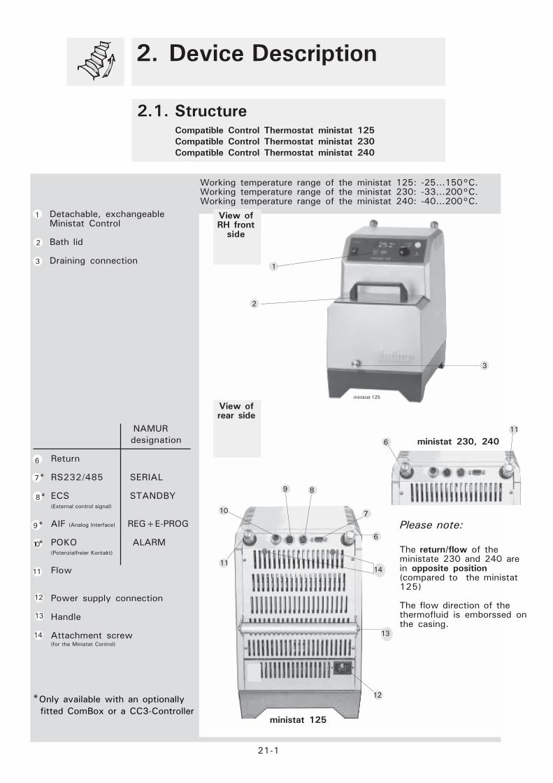
Working temperature range of the ministat 125: -25...150°C.Working temperature range of the ministat 230: -33...200°C.Working temperature range of the ministat 240: -40...200°C.
21-1
Detachable, exchangeableMinistat Control
Bath lid
Draining connection
2. Device Description
2.1. Structure
Compatible Control Thermostat ministat 125
Compatible Control Thermostat ministat 230
Compatible Control Thermostat ministat 240
2
1
3
7*
10
13
12
3
9
6
1
Return
RS232/485 SERIAL
ECS STANDBY(External control signal)
AIF (Analog Interface) REG+E-PROG
POKO ALARM(Potenzialfreier Kontakt)
Flow
Power supply connection
Handle
Attachment screw(for the Ministat Control)
11
6
8
7
11
12
13
14
14
Please note:
The return/flow of theministate 230 and 240 arein opposite position(compared to the ministat125)
The flow direction of thethermofluid is emborssed onthe casing.
6
11
ministat 125
ministat 230, 240
ministat 125
10*
2
NAMUR
designation
8*
9*
*Only available with an optionally
fitted ComBox or a CC3-Controller

22-1
Digital status display
Prompt for a temperatureset-point, input confirmation(data transfer)
Call of the user menu forconvenient handling
On/Off key to start/stopthermoregulation
Activity indicator LEDs
over-temperature protectiondevice
Encoder/ rotate:Entry of Program numbers,step numbers, parameters(e.g. temperature set-point)
Encoder/ press:Input confirmation(data transfer)
Pt100 sensor socket
RS 232/485 interface
Power switch
Display,controlpanel
Process temperature control active(green LED), only with cc2 and cc3:Temperature is measured by a process
sensor located at the point of control , e.g.
in a reactor.
Heating active (yellow LED)
Cooling /compressor active (blue LED)
Pump active (greene LED):Thermal fluid is beeing pumped through the
connected application, e.g. around the
reactor jacket.
Connec-tions
R2
R3
R1
R4
R5
R6
R7
R8
R51
R9
2. Device Description
2.2. ControllerMinistat Control cc1
Ministat Control cc2
Ministat Control cc3
R2
R1
R3
R1
R6
R2 R4
Activityindicator
R52
R54
R53
R51
R5
R6
R7
R1
R5
R7
R8
R6
R2
R10
R10
R10
R9
R3
R10R7
R8
R5
R54
R53
R52
LEDs

Commissioning
3


Preparatory
Measures
for Com-
missioning
Positioning
Please Note:
All the safety instructions are vital and must be considered duringthe operation of the unit in compliance with the operating instructions.
Location
31-1
Plan the thermoregulation target and procedure.Determine the device configuration and system structure.Select an appropriate thermal fluid.Selection criteria for thermal fluids: Temperature range of thethermostat, application restrictions building safety regulations, yourprojected working temperature, viscosity, flash point.Position thethermostat and external devices on a stable and even surface. Ensurethat the surface can safely hold the weight of the thermostat and
3. Commissioning
3.1. Safety Instructions and Principles
Caution! Potential risk of injury and material damage:Keep the device upright during transport.Place the device in an upright and stable position and make sure that itcannot tilt over.Keep the vicinity of the device clean: Prevent slip and tilting hazards.Lock the wheels of floor-mounted devices once you have positionedthem as desired!Useful note: Place appropriately large collecting trays under the thermostat and
the application.
The operation on the unit is only allowed in a normal surroundingaccording to DIN EN 61010-1:2001:
- Only indoor use.- To be used in a hight up to 2000m.- Place the device on a firm, level, non flammable and non-slipsurface.- Place the device at a distance to walls and the ceiling that permitssufficient air circulation (heat dissipation, supply of fresh air for thethermostat and the workspace). A water-cooled unit requires aminimum distance of10 cm and an air-cooled unit needs aminimum of 20 cm.- Ambient temperature min. 5°C to max. 32 °C.- Maximum relative humidity 80% for temperatures to 32°C.- Keep power and waterlines as short as possible.- The device should not be placed such that the access to theisolator is obstructed.- Line voltage changes should not exceed +10% of the mainsvoltage.- Transient overvoltages, as they typically occur in the supplynetwork.- applicable degree of pollution: 2.- Overvoltage class II.- Safety class system: IP20
The workspace of the thermostat must comply with local workplace safety regulations(ArbStättV 20. März 1975 zuletzt geändert BGBl. I 1996)

Please Note: All the safety instructions are vital and must thus be
considered on the job in compliance with the present operating
instructions..
31-2
3. Commissioning
3.1. Principles, Media and Safety Instructions
The operating instructions include additional safety instructions. These areidentified through a triangle with an exclamation mark. Thoroughly read andheed the instructions Non-observance may involve considerable consequencessuch as device damage, physical damage or personal injury with fatalconsequences.
WorkspaceThe workspace is defined to be at the control panel in front of the thermostat.The workspace is further defined by the peripheral equipment connectedby the customer. The customer is responsible for taking suitable safetymeasures.
Safety Devices
^ Overtemperature protection^ Low liquid level protection^ Mains failure automatic^ Alarm functions
Hazardous emission of fluid/vapor from the thermostat or connected pipes/hoses (very hot, very cold, hazardous chemical compositions) and or fire/explosion/implosion:Strictly heed the safety instructions of the plant operator relating to the riskof injury and danger to life as well as to the limitation of damage.Observe the instructions included in the safety data sheet of the respectivethermofluid!
Classification according to DIN12876:
Classification Thermoregulation Technical Specifications Identificationd
fluid
I non-combustiblea Overheating protectionc NFL
II combustibleb Adjustable overheating protection FL
III combustibleb Adjustable overheating protection FL
Additional low-level protection
a Generally water, other fluids only if they are not combustible in thetemperature range of an individual fault.
b The thermoregulation fluids must have a combustion point of > 65 °C,i.e. when using ethyl alcohol, only supervised operation is possible.
c The overheating protection can be achieved e.g. through an appropriate filllevel sensor or appropriate temperature control devices.
d Optional according to the selection of the manufacturer
Your thermostat is classified as FL / III
DIN12876

31-3
3. Commissioning
3.1. Principles, Media and Safety Instructions
Not suitable for use as a medical device (e.g. in vitrodiagnostic procedures).
Requirements for thermofluids classified as FL:EN 61010-1: Max. permissible working temperature
25 °C below the flash point!
Maximum viscosity at the lowest working temperature: 50 mm2/s!
Maximum density of the thermofluid: 1 kg/dm³.Possible thermoregulation range within the range of the plannedminimumand maximum working temperature.
Do not use thermofluids with any of the additives ether, ester, strongmineral acids, oxidizing acids or amines. Do not use demineralized water,mineral water, sea water or CaCl brines2Compatibility with the materials used for the thermostat (stainless steel1.4301 (V2A) and with all the materials used in the system connected tothe thermostat.
For a selection of thermofluids including technical data, please refer to the topicalHuber catalog.
Please Note:
All the safety instructions are vital and must be considered on the job incompliance with the present operating instructions.
Hazardsduringthermo-regulation
Caution! Potential risk of injury and material damage during
thermoregulation:
In the course of operation of the thermostat, extreme changes intemperature and pressure and the specific characteristics of thethermal fluids used may constitute hazards.
Thermalfluid

Please Note:
All the safety instructions are vital and must be considered on the job incompliance with the present operating instructions.
Hazardsthroughemissionof gases
31-4
3. Commissioning
3.1. Safety Instructions and Principles
Caution! Potential risk of injury and material damage:The floor will be slippery when fluids have been spilt!Thermal fluids with a low flash point constitute a fire hazard!Hazard of scalding/burning when touching exposed or defectiveconnections that are hot.
Prevent overflow of the bath.Prevent leaking fluid-conveying pipes/tubes and connections.Always remove any liquids spilt on the floor immediately.Always clean contaminated devices immediately.Place an appropriately large collecting tray under your externalapplication.
Caution! Potential risk of injury and material damage:
Risk of causticization of your respiratory tracts and skin through vapors!Prevent leaks on closed external devices.Ensure good aeration and ventilation in the vicinity of the thermostat.Choose thermal fluids for thermoregulation that are not detrimental tohealth.
Hazardsthroughemissionof fluids
Currentconnection 2.2
Check the fuse, power and voltage ratings according to the data sheet(attached) and the type plate (on the rear side of the device)
2.1
2.2
Connect the power plugto the power outlet.
* Figure applies in thecountry of manufacture(Germany) only.
Shock-proof plug*for single-phase alternatingcurrent.

32-1
Verify the following:
Make sure that all connections are correct and that there are no leaks!
3. Commissioning
3.2. Preparing the thermostat for use
PreparationThermo-regulation
If you wish to thermoregulate in a bath , please take the following
into consideration:
Seal the pump manifolds with blind plugs and cap nuts (M16x1 /SW19). While doing so, counter using SW17 at the pump manifold.
If you wish to thermoregulate an externall application, please take the
following into consideration:
Remove the blind plugs and cap nuts at the pump manifolds.Replace them with suitable hose connections to your externalapplication.
Alternative
Hazard!
If hoses have to be connectedvia shut-off valves:Only close when performing workon the reactor, otherwise allwayskeep open!
Remember that thermal fluidexpands and contracts withchanges in temperature. Sealingthe external application willexpose the application to theseforces!
For more information, please refer to Chapter 4 „Thermoregulationvia Controller“.
Please consider that the return/flow of the ministat 125 are in opposite position!
ministat 240

33-1
Require
ments
Setting
the over-temperatureprotection
For detailed information on the range of accessories incl. technical data and pricequotations, please refer to the Huber catalog or contact your Huber agent.
For the ministats 125, 230, 240 theovertemperature protection is setelectronically.It is independent of the controller.Use a suitable tool (screw driver orthe like) to press the button in thecenter of the over-temperatureprotection device. Theovertemperature menu will bedisplayed.
Prepare the thermostat forthermoregulation and take safetymeasures as described below.
Setting the overtemperatureprotection device.Requirements:A suitable thermal fluid has beenselected for the processrequirements.The flash point of the thermal fluid isknown.Procedure:The over-temperature protection is setto at least 25 °C below the flash pointof the thermofluid.
Permissible temperaturerange for set-point entry
Working temperature range ofthermostat (min.)
Flash point of the thermalfluid
Over-temperature protection(Overheat)
Viscosity limit of thethermal fluid
2 T
empe
ratu
re r
ise
Working temperature range ofthermostat (max.)
Caution!The overtemperature protection is an especially important safetydevice of your thermostat. It should always be operable and betested periodically!(Refer to 41-1)
3. Commissioning
3.3. Filling Thermofluid Overtemperature protection
OVERTEMP. PROTECTION
-> Overtemp. Setp. heat.
Overtemp. Diplay
Exit
Overtemperature Setpoint Heating: overtemperature value(adjustable on the Ministat Control 22-1).Overtemperature Display: the actuell overtemperature valueis displayed.

33-2
Filling the
bath
3. Commissioning
3.3. Filling with Thermofluid
Bath thermostats
L2 Lift the bath coverFill in thermofluid.
Please note the optimum filllevel:The evaporator coil must befully covered with thermalfluid.
Close the bath cover
Caution! Potential risk of injury and material damage!
In the case of high temperatures, the bath cover and housing coverbecome very hot.Please touch the device and the cover at the grips only. Scalding hazard!
Never, under any circumstances, lift the cover of the bath duringoperation at high temperatures:
Scalding / burning hazard due to overflow of the thermofluid.Risk of causticization of your respiratory tracts and skin through vapors!
Important!
For information on thermofluids, refer to 3.1! For a selection of thermofluidsincludingtechnical data, please refer to the Huber catalog.
Please note that the medium
needs to cool to room
temperature before you replenish
thermofluid!
L2

34-1
Language
Deutsch
Minimum
set-point
Maximum
set-point
The programs for operating the thermostat are described in Chapter4 of the Operating Instructions.
When delivered the controller displays will be in German.Other options can be selected in the „Language“ menu (refer to 4.3.2):English, Francais
3. Commissioning
3.4. Major Presettings
The thermostat controls the temperature to the predefinedsetpoint.Use the SET key and the encoder to select an other setpoint.
The setting can be changed in the „Alarm Config.“ menu (refer to4.4.1):Any temperature value within the performance parameters of thethermostat (refer to the Data Sheet, Appendix or type plate.) andthe safety limits (refer to 3.1!).
Notes to the temperature limits:
- Select limits no greater than necessary- Consider the properties of the thermal fluid (flash point and viscosity)- Consider the manufacturers recommendations of your application.
Set-point

Thermoregulation via controllers
4

41-1
Checks to
be Perfor-
med:Test Arran-
gement
All the safety instructions are vital and must thus be consideredon the job in compliance with the present operating instructions.
Compare the device configuration, the system structure and theselected thermofluid to the thermoregulation target.Verify the stability of the thermostat and external devices.Make sure there are no leaking connections.Make sure the shut-off valves for thermofluid and cooling water (ifapplicable) have been opened.Check the connection to the power supply.Caution! Potential risk of injury and material damage:Slip hazard! The floor and the workspace may be slippery when fluidshave been spilt!Tilt hazard! Make sure the thermostat and external devices are in astable position.Shock hazard! Make sure the connection to the power supply isundamaged and in perfect working order.Scalding and burning hazard! Always be aware of extremetemperatures.Causticization hazard! Risk of causticization of your eyes, your skin andyour respiratory tracts through hazardous vapors (depends on thethermofluid used).Setting the overtemperature protection:(Applies to Polystats and Compatible Control Thermostats):When: Immediately after filling the system with thermofluid!Recommendation:Periodically test the function of the overtemperature protection byentering a higher setpoint, e.g. as follows:Set the overtemperature protection to 30 °C.Enter the maximum setpoint of 40 °C (since the overtemperature protection isindependent of the controller, you can enter this excessive value withoutproblems).Enter the new setpoint of 33 °C (former setpoint 20 °C); the heating will heat to33 °C, then the thermoregulation process will be stopped automatically with theerror message: „Temp“The error message will be displayed until the error has been remedied.Remedy the error. Set the overtemperature protection to a temperature above40 °C.Switch the thermostat off and then on again.
Change of fluid:Rinsing fluid and thermofluids come into contact with stainless steel(V2A), Viton and Perbunan and must be compatible with thesematerials.
Low liquid level protection:Monitor the liquid level during operation.Applies to bath thermostats (Polystats and Compatible ControlThermostats):Fill level to approx. 60 – 80 % of the bath height;for chillers: fill level to approx. 60 – 80 % on the level indicator.Thermofluid level too low: Risk of the thermostat pump running dry.The controller will report an error and stop the thermoregulationprocess.Thermofluid level too high: Overflow, soiling, slip and causticizationhazard!
Room ventilation:Sufficient aeration and venting in the vicinity of the thermostatminimizes the risk of overheating and the accumulation of harmful gasesand vapors.
Entering the minimum and maximum setpoints:In combination with the working temperature range limits, theminimum and maximum setpoints provide additional safety for thethermoregulation process. This means, accidental entry of asetpoint that is too low or too high will be rejected.
4. Thermoregulation via
controller
4.1. Safety Instructions and Principles
Safety
Measures
Please Note:

41-2
Note:To learn more about the menu and the individual menu options, pleasealso read sections 4.2 to 4.9 of the present operating instructions.
Operating
the
controller
Messages
The display willchange upon turningof the encoder
Select amenuoption Confirm your
entry1)
4. Thermoregulation via
Controller
4.1. Safety Instructions and Principles
Principles of displays and entries
During operation, ad-hoc messages may be displayed on the controller.They provide information on irregularities and hazards in the thermostat.In the case of imminent danger, the controller will display a messageand stop the thermoregulation process/switch off the thermostat at thesame time.
Salutation
Flashdisplayson thecontroller
Statusdisplay
Systemtest
Manufac-turer
Saluta-tion
The status display depends on the preset display mode (refer to 61-2).
Select theMain Menu
1) If you fail to confirm your entry within 4 minutes, your selection willnot be saved. The program returns to the status display.To exit the menu instantaneously at any point, use the Break function*:Press the SET and MENU keys simultaneously. Your selection will not besaved.
On/Off
Name of thermostat,software version
Name of thermostat,working temperaturerange
Flash display,return to thestatus display
oror or
*applies to Ministat Control CC2 and CC3 only**applies to Ministat Control CC3 only
Stored
Denied
Electronics test
Memory Test
Pump Test
Internal 17.5 C
Process n.a.
17.5 C
n.a.
20.0 C
Internal
ProcessSetpoint
**Press the On/Off key to start/stop the thermoregulation process(thermoregulation combined with circulation).For Ministat Control CC1 and CC2 during status display:Turning the encoder displays the „Temperierung Ein/Aus“ (Thermo-regulation On/Off) menuAlternative:**MasterClear function:Pressing the MENU and TEMP keyssimultaneously stops a thermoregulation program in progress or switchesoff the analog interface or switches from the digital interface remotemode to local mode.
Ministat 230 Ministat 230

42-1
4. Thermoregulation via
Controller
4.2. Main Menu
Contents
Selection
The main menu provides menu options and submenu options including allthe settings and selections required to operate the thermostat. (Refer to42-1!)1) This menu option is not available for Ministat Control cc1.2) This menu option is not available for Ministat Control cc2.
MAIN MENU:
I->2nd Setpoint 1), 2)
Alarm Clear
Alarm Config.
Analog-Interface 1), 2)
Display
Digit. Interface 1), 2)
Venting
Machine Options
Max. Heat Power
Calibration Prog.
Compressor Auto
Mains Failure Auto
Offset Calibration
PI-Parameters
Edit Program 1)
Program Start/Stop 1)
Start Ramp 1)
Acoustic Alarm
Software version
Setpoint Limits
Language
Temperature Scale
Control Mode 1), 2)
Circulation
Select Usermenu
Config Usermenu
Factory Default
Time Scale
Exit
I-> ALARM CONFIGURATION:
I-> Alarm Mode
Lower Alarm Limit
Upper Alarm Limit
Level Alarm Delay
Exit
I-> Display
I-> Display modes
optimise display
Options
Exit
I-> Digit. Interface :
I-> Hardware RS
Baud rate
Protocol
slave address
Exit
I-> 2-P.CALIBR.:
I-> Edit TCal1
Edit TCal2
Control to TCal1
Control to TCal2
Exit
I-> OFFSET CALIBRATION:
I-> internal sensor
process sensor
Exit
I-> INITIALISE:
I-> Unit Data
User menus
Programmer
All together
Exit
Main Menu Submenus
43-1
Page
43-1
47-7
47-1
47-5,6
47-2
47-2
47-4
45-2_5
44-2
46-2
47-1
43-7
46-1
45-6
441
44-1
44-1
43-2
47-3
47-8
43-1
47-1
441
47-8
47-8
43-7
45-1

43-1
4. Thermoregulation via
Controller
4.3. Utilities1. Circulation
2. Venting 3. 2. Setpoint (for Ministat Control cc3 only)
All the factory defaults can be customized in the menu.
All the factory defaults can be restored via the „Factory Default“option (with the thermoregulation function switched off). (Alsorefer to „Salutation“ 4.1).
CirculationMAIN MENU:
Calibration Prog.I-> Circulation
Compressor Auto
Venting
2. Setpoint
CIRCULATION:I-> Off
On
„Circulation“ option„Off“No pump operation (related to thethermoregulation process) or stop of thealternating pump operation.„On“Start of the alternating pump operation(without thermoregulation) e.g. to enhancethe filling procedure.
MAIN MENU:
Time ScaleI-> venting
Exit
MAIN MENU:
I-> 2. Set-pointAcoustic Alarm
Alarm Clear
please enter:2. Set-point
15.0C
Please enter:
2. Set-pointt
25.0C
VENTING:
I-> OffOn
„2nd Setpoint“ option (exclusively
available for Ministat controllers cc3)Entry of the 2nd setpoint. This setpoint isenabled only if an error occurs in theanalog control. Refer to „Analog Inter-face“!When entering the 2nd setpoint, the sameapplies as to the „standard“ setpoint: thecharacteristics of the thermofluid, thethermoregulation objective and the safetymeasures must always be taken intoconsideration.
„Venting“ option:Can be selected only with thermoregulationswitched off.Using the venting option, the pump can beoperated in intervals in alternating mode,e.g. for enhanced venting of externalapplications.
„On“The default settings for the time intervalsfor pump operation/pause may have to beedited (take into consideration theviscosity of the thermofluid and thesystem dimensions) and – at the sametime – start of the alternating pumpoperation in intervals.
„Off“ Stop the alternating pump operationin intervals.(Refer to 3.4!)
please enter:Pump ON (s)
10
Please enter:
Pump ON (s)
15
Please enter:Pump OFF (s)
10
Please enter:Pump OFF (s)
15
Caution! Potential risk of injury and material damage!
Please take into consideration the capacity and fill level of thethermostat and the connected systems as well as the viscosity andexpansion characteristics of the thermofluid used.Please prevent overflow of the fluid. Refer to 3.4!

43-2
4. Thermoregulation via
Controller
4.3. Limiting the Thermoregulation
Range4. Setpoint Limits
All the factory defaults can be customized in the menu.
All the factory defaults can be restored via the „Factory Default“option (with the thermoregulation function switched off). (Alsorefer to „Salutation“ 4.1).
WarningThe overtemperature protection is an especially important safetydevice of your thermostat. It should always be operable and thusbe tested periodically!If the actual value exceeds the set overtemperature limit, an alarmis triggered and the thermostat will cut-out the thermoregulationprocess.This process can be restarted only after the cause of the alarm hasbeen eliminated and the alarm message acknowledged.Refer to 3.1 Principles and Safety Instructions!
Setpoint
Limit
Please enter:
Minimum Set-point
5.0C
MAIN MENU:Select Usermenu
I-> Set-point limitSoftware Version
Please enter:
Maximum Setpoint
35.0C
Please enter:
Minimum Set-point
10.0C
Please enter:Maximum Set-point
170.0C
„Setpoint Limits“ option:Enter the desired minimum setpoint andconfirm your entry (e.g. 10.0 °C).
The minimum setpoint is a safety limit forthermoregulation. Where:The lowest permissible temperaturevalue >= minimum setpoint (3.1, 4.1).It is not possible to enter a setpoint lowerthan the minimum setpoint.
Enter the desired maximum setpoint andconfirm your entry (e.g. 170.0 °C).
The maximum setpoint is a safety limit forthermoregulation. Where:The highest permissible temperaturevalue <= maximum setpoint (3.1, 4.1).It is not possible to enter a setpoint higherthan the maximum setpoint.The maximum setpoint should not be setto a value lower than 5-8 degrees belowthe value set for the overtemperatureprotection. In this way, the controller cantolerate a minimum ballistic effect of theattained temperature whenthermoregulating to the maximum setpoint.

43-3
4. Thermoregulation via
Controller
4.3. Enter a Setpoint - Start
All the factory defaults can be customized in the menu.
All the factory defaults can be restored via the „Factory Default“option (with the thermoregulation function switched off). (Alsorefer to „Salutation“ 4.1).
Caution!
The overheating point and the setpoint must be 25 degrees belowthe flash point of the thermofluid and the setpoint must be abovethe temperature at which the thermofluid attains a viscosity higherthan 50 mm2/s.(3.1.!)Note: Gas venting (Prog. 55) and decalcify.
17.5C
Please enter:set-point
50 C
Entry of
SetpointPress the SET key.The setpoint will be shown on the statusdisplay.Enter the new setpoint by turning theencoder (e.g. to 50 °C).Confirm your entry by pressing the encoderor the SET key.
Minimum
setpoint
Permissible temperature range for the setpoint
(can be defined precisely to 1/10th)
Viscosity
limit
It is not possible to enter a setpoint beyond the setpoint limits.
Overtemperature
protection (overheat)
Working
Temperature
Range of
thermostat
Flash point of the
thermofluid
Maximum
setpoint
Start thermoregulation only after all the prerequisites have been met (refer
to 3 Commissioning), especially:
Suitable location (3.1)Correct connections (3.2)Ambient temperature max. 30 °C (3.1)Correct setting of the overtemperature protection (4.1)Correct setting of the setpoint limits (4.4)
Ministat cc1 and cc2 controllers:
Start the thermoregulation process by turning the encoder.
Ministat cc3 controller:
The thermoregulation process to the new setpoint is started by pressing
the TEMP key.
To stop the thermoregulation process: Refer to page 43-4!

43-4
Caution!Do not stop the thermoregulation process by pulling the power plug.When the controller is switched back on, various device messagesmay be displayed and faults may occur.
Abort
When you press the On/
Off key or the power
switch to stop the
thermoregulation process,
all the LEDs will go out.
4. Thermoregulation via
Controller
4.3. Terminating the Thermoregulation
Process
Ministat Control cc1/cc2: The thermoregulation process can beaborted at any time by pressing the power switch. You can alsoturn the encoder until the „Thermoregulation“ menu is displayed, inwhich you can select „Off“ or „On“.
Ministat Control cc3: The thermoregulation process can be abortedat any time by pressing the On/Off key on the controller.
Actuate the power switch of the thermostat to interrupt the powersupply.

44-1
4. Thermoregulation via
Controller4.4. Editing Default Settings
1. Restoring the factory default2. Selecting a language for the controller display3. Temperature scale4. Control mode – internal/ external
All the factory defaults can be customized in the menu.
All the factory defaults can be restored via the „Factory Default“option (with the thermoregulation function switched off). For thispurpose, proceed as described below. (Also refer to „Salutation“4.1).
Language:I-> Deutsch
EnglishFrancais
MAIN MENU:
Set-point limitsI-> Language
Temperature Scale
INITIALISE:
User menus
I-> All together Exit
INITIALISE:I-> Unit Data
Programmer User menus
All together
Exit
MAIN MENU:
Config UserI->Factory default
„Factory Default“ option
Submenu selection:„Unit Data“: Important if you replaceddevice components or accessories.
„Programmer“Deletion of all the thermoregulation
programs
„User menus“Restores the „User menu“ factory default.„All together“Restores all the factory defaults.Caution! All the thermoregulation programsincl. ramps entered by the customer willbe deleted!„Exit“ option:The factory defaults will not be restored.
For selecting the language that is to be
Temperature Scale:
I-> Celsius
FahrenheitKelvin
MAIN MENU:
Language
I-> Temperature ScaleFor selecting the temperature unit fordisplay
Not available for Ministat Control cc1!MAIN MENU:
Temperature Scale:
I-> Control mode
For definitions of internal and external thermoregulation, pleaserefer to the Huber Glossary, keyword Control Mode – Internal,Process
Control mode:
I->Internal
Process (Cascade)
Factory
Default
Language
Temperature
Scale
Control
Mode

44-2
Test Part 1
P - portion
I - portion
* U: Ballistic effect: At the thermoregulation target, the actual value
oscillates about the setpoint.
**O: Optimum ratio between the accuracy of the controller and your
desired speed.
Rule: Fast thermoregulation due to a high P and a low I-parameterresults in a high ballistic effect.
External thermoregulation Temperature change by 20 °C after
each setting up to U* (ballistic effect)
50 1000 2000 3000 ... 10.000 ...up to Ü*e.g.12.000 0 0 0 0 0
Thermoregulation:
1. Heating by 20 °C with P/I=50/0, thencooling by 20 °C2. Heating by 20 °C with P/I=1000/0, then
cooling by 20 °C
3. Continue as described for Test Part 1 (table
above) until all the relevant P-parameters have
been tested.
4. Heating by 20 °C with P/I=12,000/1,000, then
cooling by 20 °C
5. Heating by 20 °C with P/I=12,000/2,000, then
cooling by 20 °C
6. Continue as described for Test Part 1(table above) until all the relevant I-parameters have been tested.
4. Thermoregulation via
Controller
4.4. Editing Default Settings
5. PI-Parameters
PI-Parameters
Factory Default:The P-parameter (proportional parameter) and the I-parameter(integral parameter) influence the thermoregulation behavior of yourthermostat. The factory default of the P-parameter is 5,000, thatof the I-parameter is 1,000.The factory default is well suited for a large number ofapplications.New settings:The PI-parameters can be edited as desired.Value range of the P-parameter: 50 ... 30,000Value range of the I-parameter: 0 ... 30,000
Test your thermoregulation process for optimum settings by ente-ring new value pairs for the thermoregulation mode (internal orprocess
Test Part 2
P - PortionI - Portion
External thermoregulation Temperature change by 20 °C after
each setting up to O**
12.000 12.000 12.000 12.000 1.000 2.000 5.000 ... up to O** e.g. 15.000
PI-Test MAIN MENU:
Offset CalibretionI-> PI-Parameter
PowerOff AutoStart
Please enter:
P-Intern
2500
Please enter:
P-Internal
50
Please enter:I-Internal
1000
Please enter:
I-Internal
0

45-1
4. Thermoregulation via
Controller
4.5. Convenient Thermoregulation –
Programs1. Start Ramp (for Ministat Control cc2/cc3 only)
All the factory defaults can be customized in the menu.
All the factory defaults can be restored via the „Factory Default“option (with the thermoregulation function switched off). (Alsorefer to „Salutation“ 4.1).
Caution!The setpoint must be 25 degrees below the flash point of thethermofluid and above the temperature, at which the thermofluidattains a viscosity higher than 50 mm2/s. (3.1.!)
Start
Ramp
Please enter:
Time (min)
90
Please enter:
Go to temperature
70 C
MAIN MENU:Start/stop Program
I-> Start RampTemperature Scale
Please enter:Go to temperature
20 C
If you want to change the working temperature slowly andsmoothly instead of suddenly, you should implement the setpointchange via a ramp.
„Start Ramp“ option:
Enter the desired final temperature of theramp (ramp setpoint), e.g. 70 °C.
Enter the time (in minutes) thethermoregulation to the ramp setpointshould take, e.g. 90 minutes.
Starting the ramp:The ramp will automatically be startedonce you have confirmed the timeparameter.
Completion of the ramp:Once the ramp setpoint has been reached(e.g. after 90 minutes), the thermostat willkeep the new actual temperatureconstantly on the new value (e.g. 70 °C
Interrupting the ramp:The ramp can be interrupted in the courseof the process by entering a new setpoint(SET/encoder).
Please enter:
Time (min)
1

45-2
4. Thermoregulation via
Controller
4.5. Convenient Thermoregulation –
Programs2. Edit Program
(Exclusively for Ministat Control cc2/ cc3)
All the factory defaults can be customized in the menu. All thefactory defaults can be restored via the „Factory Default“ option(with the thermoregulation function switched off). (Also refer to„Salutation“ 4.1).
Edit
Program
MAIN MENU:
PI-ParametersI-> Edit Program
Start Progr.
PROGRAMMER:
I-> Program 0Program 1
Program 2Program 3
Program 4Program 5
Program 6Program 7
Program 8Program 9
exit
„Edit Program“ option
Options in the „Programmer“ (PR)submenu: 10 Programs„Program 1“ optionUpon initial commissioning, all theprograms will still be „empty“, i.e. theyhave not been assigned any segments. Inthe course of the application, theseprograms may be completely filled withsegments.For further programs, you may edit existingones.
Creation of a separate thermoregulation programMinistat cc2 controller: 1 thermoregulation program for editing (canalways be overwritten) with as many as 5 segments.Mionistat cc3 controller: 10 thermoregulation programs forselecting and editing (can always be overwritten). A total of 50segments are available.One segment can maximally span a period of 54 hours.Programming is done in steps according to the „Edit Program“menu item.
Planning (Example):A fluid in an external bath is to be heated and cooled in 3 steps.The heating process is to be temperature-stable and the coolingprocess time-stable. For the time it takes to cool the bath, anagitator is to be controlled via the potential-free contact.At the end of the program, the thermostat is to maintain the bath
Caution!
The setpoint must be 25 degrees below the flash point of thethermofluid and above the temperature at which the thermofluidattains a viscosity higher than 50 mm2/s. (4.1.!)
Example:
Programm 0
T (°C)
60
20
-10
30 36 46 t (min)
Segment 0 Segment 1 Segment 2

45-3
4. Thermoregulation via
Controller
4.5. Convenient Thermoregulation –
Programs3. Edit Program (exclusively for Ministat Control cc2/ cc3)
Edit
Program FUNCTIONS PR:
Attach SegmentI-> insert Segment
modify SegmentDelete Segment
show SegmentDelete Program
Exit
Submenu selection:„Programmer“ (PR)/ „Program 0“/„Functions PR“:„Program 1“ options„Attach Segment“ (for the 1st segment, thiscorresponds to „Insert Segment“). Theparameters for the 1st segment are defined inthe following.(Refer to the example of program 0 on page
45-2!)
PROGRAM NO.1:
I-> Set point SegEndSegment period
Modify Segment Control mode
Options Save & exit
Exit
„Setpoint SegEnd“ option: entry of the setpoint for the 1st segment of
the 1st program, e.g. 60 °C.
Please enter:
Set point SegEnde
60.0 C
Please enter:
Set point SegEnde
0.0 C
Please enter:
Segment period (s)
1800
Please enter:Segment period (s)
1
PROGRAM NO.1:
Set point SegEndSegment period
I-> Control modeOptions
Save & exit Exit
CONTROL MODE:Internal
I-> Process (cascade)
TEMPERIERMODUS:I-> Intern
Extern
CONTROL MODE:I-> Internal
Process (cascade)
STABILITY:I-> Time-stable
Temperature-stable
OPTIONs PR:
Pot.free ContactAnalog Output
End condition-> Stability
exit
AT SEGMENT-END:stop regulation
I-> continue loop
OPTIONs PR:
Pot.free ContactAnalog Output
I-> End conditionStability
exit
„Stability“ option, e.g. „Time-Stable“ for the 1st Segment of the
1st program.
Time-Stable: The segment period entered has priority for the segment end.
Temperature-Stable: The „Setpoint SegEnd“ has priority for the end of the
segment.
„Options“ menu option: Selection of the „End condition“ for the 1st
segment of the 1st program, e.g. „Continue“, i.e. the temperaturevalue of the segment end is maintained. („Stop Regulation“ =thermoregulation to the former setpoint at the end of the segment)
„Control Mode“ option: example: selection of external thermoregulation.
„Segment period“ option: entry of the time period for the 1st segment of
the 1st program, e.g. 1800 seconds.
PROGRAMM NO.1:Set point SegEnd
Segment periodModify Segment
Control modeI-> Options
Save & exit Exit
PROGRAM NO.1: Set point SegEnd
I-> Segment periodModify Segment
Control mode Options
Save & exit Exit

45-4
4. Thermoregulation via
Controller
4.5. Convenient Thermoregulation –
Programs4. Edit Program
(Exclusively for Ministat Control cc2/ cc3)
All the factory defaults can be customized in the menu.All the factory defaults can be restored via the „Factory Default“option (with the thermoregulation function switched off). (Alsorefer to „Salutation“ 4.1).Select „Exit“ to return to the superordinate level
Edit
Program
„Save & Exit“ option: Saving of all the data forthe 1st segment in the 1st program. The 1st
program has thus been created.If you exit the „Program 1“ level without „Save& Exit“, all the data entered for this segment upto now that have not yet been saved will bediscarded.After „Save & Exit“ the program will return tothe superordinate level „Functions PR“.
TEMPERIERMODUS:
I-> InternExtern
CONTROL MODE:
I-> Internal
Process (Cascade)
STABILITY:
time-stableI-> Temperature-stable
POCO ACTIVE:
NoI-> Yes
„Functions PR“ option, „Show segment“ option: this is where you cancheck your entries. Press the MENU key to exit the display.The program will return to „Functions PR“, where you select „AttachSegment“ as shown in the example. The entries now correspond to thosefor segment 1 taking the values from our example. In this segment, youmust additionally select the potential-free contact for controlling theagitator in segment 2.
OPTIONs PR:
Pot.free ContactAnalog Output
End conditionStability
I->exit
PROGRAM NO.1: Set point SegEnd
Segment period Control mode
OptionsI-> Save & exit
Exit
Select „Exit“ to return
to the superordinate
level „Program 1“.
Prog:0 Seg:0Temp:60 Contr:Cas
Time:1800 Stab:TimePoco:0 AnO:0
Please enter:
Segment period (s)
360
Please enter:
Set point SegEnd
-10.0 C
Please enter:Set point SegEnd
60.0
Please enter:
Segment period (s)
1800
FUNKTIONS PR:
I-> Attach Segment insert Segment
modify Segment
PROGRAM NO.1:Set point SegEnd
I-> Segment period Control mode
PROGRAM NO.1:
Set point SegEndSegmentdauer
I-> Temperiermodus
TEMPERIERMODUS:
I-> InternExtern
CONTROL MODE:
Internal
I-> Process (Cascade)
OPTIONS PR:
I-> Pot.free contactAnalog output
End condition
AT SEGMENT-END:I-> Stop regulation
Continue loopRepeat
OPTIONS PR:Analog output
I-> End conditionStability
OPTIONS PR:
End condition-> Stability
exit
OPTIONS PR:
End conditionStability
-> exit
PROGRAMM NO.1:
OptionsI-> save segment
exit
Potential-free
contact
FUNKTIONS PR:Delete Segment
I-> show SegmentDelete Program
Exit
PROGRAM NO.1:
Sollwert SegEndeSegmentdauer
I-> Temperiermodus

45-5
4. Thermoregulation via
Controller
4.5. Convenient Thermoregulation –
Programs5. Edit Program
(Exclusively for Ministat Control cc2/ cc3)
All the factory defaults can be customized in the menu.All the factory defaults can be restored via the „Factory Default“option (with the thermoregulation function switched off). (Alsorefer to „Salutation“ 4.1).Select „Exit“ to return to the superordinate level.
Edit
Program
TEMPERIERMODUS:
I-> InternExtern
CONTROL MODE:
I-> Internal
Process (Cascade)
STABILITY:Time stable
I-> Temperature stable
„Functions PR“ option, „Show segment“ option: this is where you cancheck your entries. Press the MENU key to exit the display.
The program will return to „Functions PR“, where you select„Attach Segment“ as shown in the example. The entries nowcorrespond to those for segment 1 taking the values from ourexample. In this segment, you must additionally select the potenti-al-free contact for controlling the agitator in segment 2.
Please enter:
Period Segm. (s)
600
Please enter:
Set point SegEnd
20.0 C
Please enter:Set point SegEnd
-10.0
Please enter:
Period Segm. (s)
360
FUNKTIONS PR:
I-> Attach SegmentInsert Segment
Modify Segment
PROGRAMM NO.1:Set point SegEnd
I-> SegmentTemperiermodus
PROGRAMM NO.1:
Set point SegEnd Period Segm.
I-> Control mode
TEMPERIERMODUS:
I-> InternExtern
CONTROL MODE:
Internal
I->Process (Cascade)
AT SEGMENT-END:
Stop regulationI-> Continue loop
OPTIONS PR:
Analog outputI-> End condition
Stability
OPTIONS PR:End condition
-> Stabilityexit
OPTIONS PR:End condition
Stability-> Exit
PROGRAMM NO.1:Options
I-> save & exitExit
You have now created a thermoregulation program with 3 segmentsaccording to our example.
Caution!
Before activating the program, make sure you are using a suitablethermofluid!The setpoint must be 25 °C below the flash point of the thermo-fluid and above the temperature at which the thermofluid attains aviscosity higher than 50 mm2/s. (3.1.!)Please Note:You cannot create thermoregulation programs with the Ministatcontroller cc1.You can create one thermoregulation program with the Ministatcontroller cc2.You can create 10 thermoregulation programs with the Ministatcontroller cc3.

45-6
4. Thermoregulation via
Controller
4.5. Convenient Thermoregulation –
Programs6. Start Program (Exclusively for Ministat Control cc2/ cc3)
Start/Stop
Program
MAIN MENU:Software Version
I-> Start/Stop ProgramStart Ramp
„Start/Stop Program“ option
If no program has been started:Submenu selection:„Program 1“ example Ministat cc3:10 programs / 50 segments(However one program cannot containmore than 40 segments)
Ministat Control cc2: 1 program / 5segments
If a program has already been started:Submenu selection:„Program Pause“„Program Continue“„Go To Segment No.“„Program Stop“„Exit“
Program 1 will be started.
Aborting the thermoregulation programWith Ministat controller cc2: Power switchor new menu (using„Program Stop“).With Ministat controller cc3:Break function (press the MENU and On/Off keys simultaneously).Alternative: Power switch or new menu.
Standard end of the thermoregulationprocess once the thermoregulation pro-gram has been completely executed,according to:- programmed segment end (thetemperature of the last segment setpoint ismaintained (Continue) or thermoregulationto the last setpoint entered outside theprogram) or repeating of Temp. Program.- Stability: Time-Stable (i.e. after theprogrammed segment period has elapsed)or Temperature-Stable (i.e. after thesegment setpoint has been attained).
Once the program has been completelyexecuted, the status display will beshown.
Progr.:1 Segm.:1
Internal 21.2Process 17.5
Setpoint 17.6
60.0 C
PROGRAMMER:I-> Program 1
Program 2Program 3
Program 4Program 5
Program 6Program 7
Program 8Program 9
Program 10 Exit
Caution!
Before activating the program, make sure you are using a suitablethermofluid!The setpoint must be 25 °C below the flash point of the thermo-fluid and above the temperature at which the thermofluid attains aviscosity higher than 50 mm2/s. (4.1.!)
„Internal“:development of theinternal actual value
„Process“:development of theexternal actual value
„Setpoint“:Calculated actualsetpoint.
SERVICE-PROGRAM:
Program Pause
Program Continue
Go To Segment No.
Program stop
Exit

46-1
4. Thermoregulation via
Controller
4.6. Calibration1. Calibration Program
All the factory defaults can be customized in the menu.
All the factory defaults can be restored via the „Factory Default“option (with the thermoregulation function switched off). (Alsorefer to „Salutation“ 4.1).
Calibration
Prog.
The two-point calibration includes all the values between T1 andT2. With offset calibration, on the other hand, the entiretemperature level is shifted by one value on a linear level.
MAIN MENU:Analog Interface
I-> Calibration prog.Circulation
2-P.CALIBR. INTERNAL:I-> Edit T-Cal1/2
Control to T-Cal1Control to T-Cal2
exit
2-P.calibration:
Edit TCal1I-> Edit TCal2
Control to T-Cal1Control to T-Cal2
exit
2-P.calibration:Edit TCal1
Edit TCal2I-> Control to T-Cal1
Control to T-Cal2exit
„Calibration Prog.“ optionIs used exclusively to calibrate the internalsensor.Use a calibrated reference thermometer asa second temperature sensor forcalibration.
Submenu selection: „Edit TCal1/2“
Entry of the 1st of two calibrationtemperatures, e.g. change from 6°C to10 °C.
Entry of the 2nd of two calibrationtemperatures, e.g. change from 100°C to40 °C.
Submenu selection: „Control to TCal1“
Start thermoregulating until the 1st
calibration temperature has been reached.If your reference thermometer indicates theset temperature reliably, compare the valueto the actual value display of the Ministatcontroller. Deviations can be correctedusing the encoder.Submenu selection: „Control to TCal2“Proceed as described for TCal1.Exit the menu once you have completedthe calibration procedure.
Please enter:Set-point TCal1
6 C
2-P.calibration:
Edit TCal1Edit TCal2
Control to T-Cal1I-> Control to T-Cal2
Exit
Please enter:
Set-point TCal1
10 C
please enter:set-point TCal2
100 C
Please enter:set-point TCal2
40 C
46-2
4. Thermoregulation via
Controller
4.6. Calibration2. Offset calibration
All the factory defaults can be customized in the menu.
All the factory defaults can be restored via the „Factory Default“option (with the thermoregulation function switched off). (Alsorefer to „Salutation“ 4.1).
Offset-Calibration
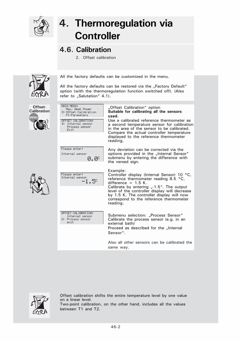
Offset calibration shifts the entire temperature level by one valueon a linear level.Two-point calibration, on the other hand, includes all the valuesbetween T1 and T2.
MAIN MENU:Max. Heat Power
I-> Offset CalibrationPI-Parameters
OFFSET CALIBRATION:I-> Internal sensor
Process sensorExit
Please enter:
Internal sensor
0.0C
OFFSET CALIBRATION:
Internal sensorI-> Process sensor
exit
„Offset Calibration“ optionSuitable for calibrating all the sensorsused.Use a calibrated reference thermometer asa second temperature sensor for calibrationin the area of the sensor to be calibrated.Compare the actual controller temperaturedisplayed to the reference thermometerreading.
Any deviation can be corrected via theoptions provided in the „Internal Sensor“submenu by entering the difference withthe versed sign.
Example:Controller display (Internal Sensor) 10 °C,reference thermometer reading 8.5 °C,difference = 1.5 K.Calibrate by entering „-1.5“. The outputlevel of the controller display will decreaseby 1.5 K. The controller display will nowcorrespond to the reference thermometerreading.
Submenu selection: „Process Sensor“Calibrate the process sensor (e.g. in anexternal bath)Proceed as described for the „InternalSensor“.
Please enter:
Internal sensor
-1.5C
Also all other sensors can be calibrated thesame way.

47-1
4. Thermoregulation via
Controller
4.7. Editing Further Settings 1. Display
2. Time scale3. Mains failure auto
DISPLAY:I->Display mode
optimise displaydisplay
Exit
MAIN MENU:
Digit. InterfaceI-> Display
Edit Program
„Display“ option
Selection in the „Display Modes“submenu:„Standard“:Single-line status display, the actual valueof the controller temperature (according tothe control mode (internal or processtemperature) is displayed in maximum fontsize.„Double“:Double-line status display, the actualvalues of the internal temperature and the(external) process temperature aredisplayed in medium font size.„Double+Setp“:Three-line status display, the actual valuesof the internal temperature and the processtemperature as well as the setpoint aredisplayed in small font size.„Service2“:Four-line status display, the actual valuesof the internal temperature and the processtemperature (external) as well as of theadditional temperature sensors 1 and 2 aredisplayed in small font size.
Selection in the „Display Angle“ submenu:Selection of a value to change the displayangle by turning the encoder.
„Time scale“: optionSelect the unit on which the timing of thethermoregulation programs is to be based.
DISPLAY MODES:Standard
I-> DoubleDoublel+Setp.
Service1Service2
exit
POWEROFF AUTOSTART.:
I->Off
On
MAIN MENU:
PI-Parameters
I-> PowerOff AutoStart
Select Usermenu
TIME SCALE:Seconds
I-> Minutes
MAIN MENU: Temperature Scale
I-> Time ScaleVenting
Display
Time
Scale
Mains
Failure
Auto
Please Enter:
Optimise display
DISPLAY:Display modes
-> optimise displayExit
„Mains Failure Auto“ option„Off“ After mains failure, manual input isrequired to continue the thermoregulationprocess.„On“ After mains failure, thethermoregulation process is continuedautomatically. The setpoint programmedlast will be used for thermoregulation.
Refer to 4.1 Safety Instructions!

47-2
4. Thermoregulation via
Controller
4.7. Editing Further Settings 4. Alarm Configuration
5. Alarm Clear
The alarm concept plans two types of alarms:“hard“ alarms alwayslead to a „malfunction“ and can only be eliminated by switchingoff the power supply. „Soft“ alarms lead either to a „malfunction“or are generated as a warning.The soft alarms lead to malfunctionwhen the stop mode is selectedin the configuration menu (factory default). Otherwise, a warningwill be displayed (in the run mode).The user can delete a warningin the menu alarm config.\ alarm clear. A warning can beoverwritten by a „hard“ alarm anytime.The authorization for „soft“ alarms consists of the fact that thecustomer can at least operate temporarily on the device when smallerrors occured. The error condition should be repaired inappropriate time.A list of soft alarms is to be found in chapter 6.4.
ALARM CLEAR:I-> Restart
Continue
„Alarm stop Mode“ preselection„Stop Mode“:The thermoregulation process will bestopped.Once the cause of the alarm has beeneliminated and the alarm message hasbeen acknowledged, it can be restartedmanually.„Alarm Mode“ preselection„Run Mode“:After the cause auf the alarm has beeneliminated: „Restart“: Thethermoregulation process is continued. themessage disapears.„Continue“: The thermoregulation processwill continue. The message is notdisplayed anymore.
Alarm
Configuration
Selection of the „Alarm config“ menu.
Selection in the „Alarm mode“ submenu:Run mode: ref. to „Alarm clear“!Stop mode: ref. to „Alarm clear“!
Submenu Selection:„Lower Alarm Limit“ / „Upper Alarm Limit“The lower and upper alarm limits definethe temperatures that trigger an alarm andstop the thermoregulation process,depending on the Alarm Mode settings.Refer to 4.1 Safety Instructions!
„Level Alarm Delay“The level alarm delay is defined by enteringthe delay time in seconds.The minimum filling level is supervised.A brief falling under lower level is tolerable.
„Alarm Clear“ optionAcknowledge the alarm.
In the case of software-monitored alarmmessages, the thermoregulation process iscontinued.The alarm message will persist until thecause auf the alarm has been eliminatedand the alarm message has beenacknowledged.
MAIN MENU:
Acoustic AlarmI-> Alarm clear
Alarm config.
ALARM-STOP MODE:Please switch unit
off and on
Alarm
Clear
Please enter:
Level alarm delay
40
ALARM MODE:
Run Mode->Stop Mode
MAIN MENU:Alarm clear
I-> Alarm config.Analog Interface
Please enter:Upper Alarm Limit
40.0C
ALARM CONFIG.:I-> Alarm mode
Lower Alarm Limit Upper Alarm Limit
Level alarm delayExit
ALARM CLEAR:I-> Restart
Continue

47-3
4. Thermoregulation via
Controller
4.7. Editing Further Settings6. Compressor Automatic
7. Maximum Heating Power 8. Software Version
13. SoftwareversionAll the factory defaults can be customized in the menu.
All the factory defaults can be restored via the „Factory Default“option (with the thermoregulation function switched off). (Alsorefer to „Salutation“ 4.1).
„Max. Heat Power“ option
Enter the desired maximum heating powerin percent.This is required for devices equipped witha heater and a compressor (chiller).The heating power must be reduced toenable simultaneous operation of heaterand compressor with a view to the fusingof the device.
Heating
Capacity
Compressor
AutoSelection of the compressor starting mode
„Automatic“The compressor will start automaticallydepending on the topical demand. Thechiller will work on demand only.Benefit: Saving of energy.Drawback: Heating time (idle time) in thecase of a sudden demand.
„Always On“The compressor remains switched on,continuous chiller operation.
„Always Off“The compressor remains switched of, thechiller is not in operation.
MAIN MENU:
CirculationI-> Compressor Auto
Config. Usermenu
COMPRESSOR AUTO:I-> Automatic
Always onAlways off
Please enter:Max. heat power (%)
100
MAIN MENU:
Machine FeaturesI-> Max. Heat Power
Offset Calibration
„Software Version“ option
For example:04.00s vom 19.02.2003, 15.41 PM.
Softwareversion
MAIN MENU:
Set-Point limitsI-> Software version
Start/Stop Program
SOFTWARE:
Series No.: 0Version 04.00s
Date 19.02.03. 15.41

47-4
4. Thermoregulation via Controllers
4.7. Editing Further Settings 9. Machine Options
Machine Features:Various settings are possible depending on the equipment of thedevice. These can be selected in the submenu displayed. Onlythose options actually installed in the device are displayed.
Machineoptions
Here, the nominal speed can be set fordevices equipped with variable-speed
Various external control signal (ECS )functions can be triggered for devices withexternal control signal. For this reason, asubmenu is displayed here for selecting thefunctions when the external control signalis enabled.„Off“ External control input is not assignedany function
„Standby“ When the external control signalis enabled, thermoregulation is switched onand remains active until the external controlinput is disabled.
„Act. 2nd setpoint“: activate the 2ndsetpoint. The active-on principle is beeingused.therefore applies to this protectivefunction:
it is thermoregulated on the „normal“setpoint value, as long as the ECS isactive. The 2nd setpoint is effective whenthe dry contact at ECS opens and stayseffective when the ECs is reactivated.
„Exit menu“: Settings are not changed, exitmenu.
„Machine Options“ menu option
Without significance
Settings are not changed, exit menu.
MENu OPTION:
I-> Reserverd
MENu OPTION:
I-> Ext. Control Signal
MENu OPTION:
I-> Ext. Control Signal
-Exit-
MENu OPTION:
I-> Exit
Main menu:
LanguageI-> Machine Options
Max. Heat Power
MENu OPTION:
I-> Ext. Control Signal
-Off-
MENu OPTION:
I-> Ext. Control Signal
-Standby-
MENu OPTION:
I-> Ext. Control Signal
-Act. 2nd Setpoint-
MENu OPTION:
I-> Pump Speed

47-5
4. Thermoregulation via
Controller
4.7. Editing Further Settings10. Analog Interface – Parameter Input
Applies to all thermostats with the Ministat Control cc3 !
All the factory defaults can be customized in the menu. All thefactory defaults can be restored via the „Factory Default“ option(with the thermoregulation function switched off). (Also refer to„Salutation“ 4.1).
AnlogInterface
„Analog Interface“ (AIF) option: Thethermoregulation process is controlled viaan analog signal (currents from 4 to 20mA), the strength of which represents thesetpoint. The temperature range can be setby the user. The difference between Zeroand Span must be at least 10 K but mustnot exceed 320 K.
Submenu selection: „Temp. T1 (Zero)“
Default „Temp.1“: Lower limit of thetemperature range
Submenu selection: „Temp. T2 (Span)“
Default „Temp.2“: Upper limit of thetemperature range
Submenu selection: „Param. Input“
Default: Parameter input disabled/enabledor configuration.
Submenu selection: „Configuration“
Default: Measured value of the analog-digital converter at T1/T2: „AN. CURROK?- Yes“ if the analog device (providedby the customer) is synchronized with theHuber controller.„AN. CURR OK?- No“ if the analog device(provided by the customer) must beresynchronized with the Huber controller.Automatic return to the menu.
Selection in the „If Error at Analog“submenu:Response to errors: Cut-out or enabling ofthe 2nd setpoint (ref. to 6.4.)
MAIN MENU:Alarm mode
I-> Analog InterfaceDisplay
ANALOG INTERFACE:I-> Temp. T1 (Zero)
Temp. T2 (Span)Conf. Input
Conf. OutputExit
Please enter:
Temp. 1 (zero)
5.0C
ANALOG INTERFACE:
Temp. T1 (zero)I-> Temp. T2 (Span)
Conf. InputConf. Output
Exit
Please enter:Temp. 2 (Span)
35.0C
ANALOG INTERFACE:
Temp. T1 (Zero)Temp. T2 (Span)
I-> Conf. InputConf. Output
Exit
ANALOG INPUT:
AIF-Input Off AIF -> Set-point I-> Adjust Exit
When the AIF is enabled, the input current determines the setpoint.If a setpoint is entered via the CC3 keyboard in this period, thissetpoint will be enabled only after the AIF has been disabled. Thedefinition of the setpoint via the AIF can be aborted with theMasterClear function. The setpoint defined prior to enabling the AIFwill then be used for thermoregulation.Caution! The Electronic may be destroyed if currents exceeding 20mA are used and/or if the polarity is confused!
ANALOG INPUT:
I-> AD-value at T1AD-value at T2
On error AnalogExit
ANALOG INPUT:AD-Value at T1
AD-Value at T2I-> On error Analog
Exit
ANALOG INPUT:
AD-Value at T1AD-Value at T2
I-> On error AnalogExit
47-6
4. Thermoregulation via
Controller
4.7. Editing Further Settings 11. Analog Interface – Parameter Output Applies to all thermostats with the Ministat Control cc3!
All the factory defaults can be customized in the menu. All thefactory defaults can be restored via the „Factory Default“ option(with the thermoregulation function switched off). (Also refer to„Salutation“ 4.1).
AnlogInterface
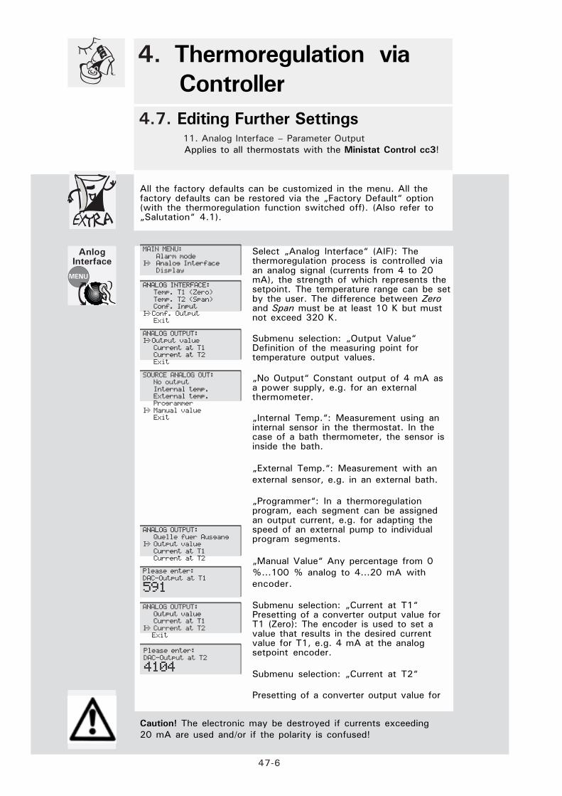
Select „Analog Interface“ (AIF): Thethermoregulation process is controlled viaan analog signal (currents from 4 to 20mA), the strength of which represents thesetpoint. The temperature range can be setby the user. The difference between Zeroand Span must be at least 10 K but mustnot exceed 320 K.
Submenu selection: „Output Value“Definition of the measuring point fortemperature output values.
„No Output“ Constant output of 4 mA asa power supply, e.g. for an externalthermometer.
„Internal Temp.“: Measurement using aninternal sensor in the thermostat. In thecase of a bath thermometer, the sensor isinside the bath.
„External Temp.“: Measurement with anexternal sensor, e.g. in an external bath.
„Programmer“: In a thermoregulationprogram, each segment can be assignedan output current, e.g. for adapting thespeed of an external pump to individualprogram segments.
„Manual Value“ Any percentage from 0%...100 % analog to 4...20 mA withencoder.
Submenu selection: „Current at T1“Presetting of a converter output value forT1 (Zero): The encoder is used to set avalue that results in the desired currentvalue for T1, e.g. 4 mA at the analogsetpoint encoder.
Submenu selection: „Current at T2“
Presetting of a converter output value for
MAIN MENU:
Alarm modeI-> Analog Interface
Display
ANALOG INTERFACE:Temp. T1 (Zero)
Temp. T2 (Span)Conf. Input
I-> Conf. OutputExit
ANALOG OUTPUT:I-> Output value
Current at T1Current at T2
Exit
SOURCE ANALOG OUT:No output
Internal temp.External temp.Programmer
I-> Manual valueExit
Please enter:
DAC-Output at T1
591
Caution! The electronic may be destroyed if currents exceeding20 mA are used and/or if the polarity is confused!
Please enter:
DAC-Output at T2
4104
ANALOG OUTPUT:
Quelle fuer AusgangI-> Output value
Current at T1Current at T2
ANALOG OUTPUT:
Output valueCurrent at T1
I-> Current at T2 Exit

47-7
4. Thermoregulation via
Controller
4.7. Editing Further Settings 12. Digital Interface Applies to all thermostats with the Ministat Control cc3!
All the factory defaults can be customized in the menu. All thefactory defaults can be restored via the „Factory Default“ option(with the thermoregulation function switched off). (Also refer to„Salutation“ 4.1).
If the analog input is enabled as the setpoint source in the menu,then this setpoint has a higher priority than the setpoint sent to thecontroller via the digital interface.
Keyboard entries are not possible in remote mode. There is onlyone exception: the MasterClear function (press the MENU andTEMP keys simultaneously). In this case, the program exits theremote mode and the controller can be operated via the keyboardagain. At the same time, the controller setpoint active prior toselecting „RS232“ or „RS485“ will be reactivated (auxiliarysetpoint).
Digital
Interface
„Digit. Interface“ optionThe controller is equipped with abidirectional RS232 interface and anRS485 interface. These digital interfacesenable remote control via a PC (Remotemode).
Submenu selection: „Hardware RS“Preselection of the RS232 (for 1 PC) orRS485 (for up to 32 PCs) interface.
Submenu selection: „Baud rate“
Preselection of the data transfer ratebetween the thermostat and the connectedPC. You can select one of five baud rates.
Factory default: 9,600 Baud
Submenu selection: „Slave address“
The Huber thermostat is assigned an„address“, i.e. an assignment across theentire device system of the user. Selectionrange: 0 to 99.
MAIN MENU:
Control ModeI-> Digit.Interface
Display
DIGIT. INTERFACE.:
I-> Hardware RSBaud rate
Slave addressexit
HARDWARE RS:
I-> RS 232RS 485
DIG. SCHNITTST.:Hardware RS
I-> Baud rateSlave address
Exit
BAUD RATE:
1200 Baud2400 Baud
4800 BaudI-> 9600 Baud
19200 Baud
DIGIT. INTERFACE:
Hardware RSBaud rate
I-> Slave addressexit
Please enter:
Slave address
1

47-8
4. Thermoregulation via
Controller
4.7. Editing Further Settings 13. Acoustic Alarm
14. Select Usermenu 15. Configure Usermenu
All the factory defaults can be customized in the menu.
All the factory defaults can be restored via the „Factory Default“option (with the thermoregulation function switched off). (Alsorefer to „Salutation“ 4.1).
Acoustic
Alarm
MAIN MENU:
2nd StpointI-> Aucoustic alarm
Alarm Clear
The administrator password is forwarded to the user separately(on request).
Select
Usermenu
AUCOUSTIC ALARMI-> OFF
ON
„Acoustic Alarm“ option„Off“ Alarm signals and error messageswithout acoustic alarm.„On“ Alarm signals and error messageswith acoustic alarm.
MAIN MENU:PowerOff AutoStart
I-> select user menuSetpoint Limit
USER MENU:
I-> AdministratorUser menu 1
User menu 2User menu 3User menu 4
User menu 5User menu 6
User menu 7Exit
„Select Usermenu“ option:
Only the administrator can select thissubmenu after entering the correctpassword.
MAIN MENU:
Compressor AutoI-> Config. User menu
Control Mode
Please enter:
User menu
1
The „Config Usermenu“ option is visible tothe administrator only (default see above„Select Usermenu“).For this reason, only the administrator canselect this submenu after entering thecorrect password.Via the „Config. Usermenu“ option youdefine the menu options that are to bevisible in the Main Menu, i.e. the factorydefault is customized.
Config
Usermenu

Shut Down
5


51-1
Please Note:
All the safety instructions are vital and must be considered during use incompliance with the present operating instructions!
Electrical
connections
Cleaning
Transport
Caution! Potential risk of injury and material damage:
Slip hazard! The floor and the workspace may be slippery when fluidshave been spilt!Tilt hazard! Make sure the thermostat and external devices are in astable position.Shock hazard! Make sure the connection to the power supply isundamaged and in perfect working order.Scalding and burning hazard! Always be aware of extremetemperatures. Causticization hazard! Risk of causticization of youreyes, your skin and your respiratory tracts through hazardous vapors(depends on the thermofluid used).
5. Shut Down
5.1. Safety Instructions and Principles
Make sure that the power connections are in good condition. Plugs,sockets and cables must be in good order and of the correct rating. Avoidcontact with fluids.
When replacing fuses, always use fuses with the correct ratings (refer to5.3.!)
Clean and service the thermostat periodically (refer to 5.3!).Keep the vicinity of the thermostat clean!Always clean contaminated areas immediately.
Keep thermostats upright during transport.
Transport thermostats on clean, level and non-slip surfaces only.
Keep all the thermostat connectors/fittings closed.Close the valves for fluids!Protect plug-type connections using the caps provided for this purpose.

52-1
Note:The drained thermofluid must be disposed of in compliance with theinstructions of the fluid manufacturer.The drained cooling water can bedisposed of through the standard sewage.
Require-
ments
Keep at hand a collecting vessel, a suitable drain tube, a screwdriver,
compressed air and a cleaning cloth.
Terminate the thermoregulation process via menu selection or by
pressing the On/Off key (R4 with cc3). (The final temperature should be
as close as possible to the ambient temperature. Highly viscous
thermofluids may need to be above ambient temperature).
5. Shut Down
5.2. Draining, Deactivating and
Dismantling
Switching
offDisconnect the power plug.
Requirements:Caution: Risk of burns! Before draining it, allow the thermofluid to coolor warm to almost room temperature. Set the temperature to a valueslightly above room temperature for highly viscous media.Read the safety data sheet of the thermofluid in advance by all means;wear gloves, if required.
Avoid contamination in the vicinity of the thermostat through spilt orsplashed thermofluid and through escaping hazardous vapors.Use appropriate drain tubes and collecting vessels.
Draining:
Stop thermoregulation, switch off the thermostat at the power switch.If the workspace in front of the thermostat is readily accessible, the devicecan be pulled directly to the edge of the workbench, and the thermofluidcan flow freely into a collecting tank placed below the table, once the drainplug has been removed.
Otherwise, it can be drained via a suitable hose.Put one end of the drain hose into the collecting tank.Cautiously loosen the drain plug at the drain manifold. At the same time,have the end of the drain hose at hand.Screw the drain plug completely out of the thread but still push it againstthe drain manifold. Remove the drain plug and at the same time slide onthe hose.The more rapidly and smoothly this is done, the less thermofluid is spilt.Complete draining can be supported in the end by lifting the device andslightly tilting it.
DrainingThermo-
fluid
Cleaning surfaces
Cover unused electrical connectors using the protective caps supplied.
Clean the stainless-steel surfaces using steel cleaning spray (Hubercatalogue number 6283).
Carefully clean painted surfaces using a mild detergent.

53-1
Caution!The easiest and most effective method of preventing accidents andguaranteeing trouble-free operation:Keep the vicinity of the thermostat clean!Always clean contaminated areas immediately.Service the equipment periodically!
Requirements
ReplacingFuses
In the case of a failure of the automatic cut-out, determine the cause of the failure andeliminate it.Then replace the fuse.
Keep at hand a collecting vessel, a suitable drain tube, a screwdriver,compressed air and a cleaning cloth.
The thermoregulation process is terminated via menu selection or bypressing the On/Off key (R4 with cc3). (The final temperature should beas close as possible to the ambient temperature, with highly viscousthermofluids slightly above the ambient temperature).
5. Shutdown
5.3. Maintenance and Service
Cleaningthe
Surfaces
Cover unused slide-on receptacles using the protective caps supplied forthis purpose.
Clean the stainless-steel surfaces using commercial steel cleaning spray.Carefully clean painted surfaces using brine made from a mild detergent.
Caution! Disconnect the power plug bevor replacing the controller!!
If a defect comes up, you can replace the Ministat Control yourself.(When replacing the controller, please heed the safety instructions in thecontroller instruction manual.)On the rear of the thermostat, there are two attachment screws. Afteryou have loosened the two screws in the threads, apply uniformpressure to the screws to easily slide the slide-in module out to thefront.
Caution! The bath cover must be closed!!
Urgent plea:Maintain the warranty claim and the cost-efficientreplacement price by not performing any repairs by yourself.
Replacing
the
Controller

53-2
Caution!
The easiest and most effective method of preventing accidents andguaranteeing trouble-free operation!Keep the vicinity of the thermostat clean!Always clean contaminated areas immediately.Service the equipment periodically!
Maintenance
of the
Ministats
5. Shutdown
5.3. Maintenance and Service
The liquefier is on the bottom of the ministat housing.The cooling air is sucked in from below through the liquefier.Avoid light particles in the air suction area on the bottom ofthedevice.The liquefier should be cleaned from time to time.For this purpose, remove the power cable from the ministat,completely drain the bath and tilt the housing to the rear by 90°.You can clean the liquefier using a brush or vacuum cleaner. Pleasedo not use any sharp or pointed objects for this purpose.The ministat should be returned to its horizontal original positionimmediately after the cleaning procedure.
To prevent damage to the environment, dispose of „veteran“thermostats through certified expert companies only.
Disposal
Service
HotlineHotline Germany: +49 - 781 - 9603 - 244
Hotline Service Center USA: +1 - 740 - 373 - 6809
Hotline Service Center NL: +31 - 485 - 542 - 811

Appendix
6


61-1
All the factory defaults can be restored via the „Factory Default“
option (refer to 42-1).
Alarm Configuration – Upper Alarm Limit 155 °C Ministat125
Alarm Configuration – Upper Alarm Limit 205 °C Ministat230
Alarm Configuration – Upper Alarm Limit 205 °C Ministat240
Alarm Configuration – Lower Alarm Limit -30 °C Ministat125
Alarm Configuration – Lower Alarm Limit -38 °C Ministat230
Alarm Configuration – Lower Alarm Limit -45 °C Ministat240
Alarm Configuration – Level Alarm Delay 4 s
Alarm Mode Stop Mode
Analog Interface – Temp. T1 5 °C
Analog Interface – Temp. T2 35 °C
Analog Interface – Parameter Input disabled
Analog Interface–Parameter Output /Source Analog Out Internal Temp.
Analog Interface – Current at T DAC 269
Analog Interface – Current at T2 DAC 4104
Display – Display Modes Standard
Display – Display Angle 100
Digital Interface – Hardware RS RS 232
Digital Interface – Baud Rate 9600
Digital Interface – Slave Address 1
Venting Off / 10 s
Max. Heat Power 100 %
Calibration Prog. – TCal 1 0 °C
Calibration Prog. – TCal 2 100 °C
Compressor Auto Automatic
Mains Failure Auto Off
Offset Calibration – Internal Sensor 0 °C
PI-Parameters – P-Internal 2500 Ministat125
PI-Parameters – P-Internal 1125 Ministat230
PI-Parameters – P-Internal 1125 Ministat240
PI-Parameters – I-Internal 1000
Edit Program 0
Acoustic Alarm On
Setpoint 20 °C
Setpoint Limits – Minimum Setpoint 5 °C
Setpoint Limits – Maximum Setpoint 35 °C
Language Deutsch
Temperature Scale °C
Control Mode Internal
Circulation Off
Usermenu Administrator
Time Scale Minutes
2nd Setpoint 5 °C
6.1. Presettings
Standard Parameter Set - Factory Default
6. Appendix
Programs
for changing
the factory
default settings
4.7.2.
4.7.2.
4.7.2.
4.7.2.
4.7.2.
4.7.2.
4.7.2.
4.7.2.
4.7.5-6
4.7.5-6
4.7.5-6
4.7.5-6
4.7.5-6
4.7.5-6
4.7.1.
4.7.1.
4.7.7.
4.7.7.
4.7.7.
4.3.1.
4.3.7.
4.6.1.
4.6.1.
4.3.7.
4.7.1.
4.6.2.
4.4.2.
4.4.2.
4.4.2.
4.4.2.
4.5.2-5
4.7.8.
4.3.2.
4.3.2.
4.3.2.
4.4.1.
4.4.1.
4.4.1.
4.3.1.
4.7.8.
4.7.1.
4.3.2

62-1
Pt100external
RS232/
RS485
Poko
dry contact
(Potential-
free contact)
6. Appendix
6.2. Interface Specification, Data
Please adhere to the following general principles:· Always switch off all associated devices before connecting any
cables.· Only low voltages may be applied to the interfaces of the Huber
devices.· Always use an process sensor with a shielded cable. Otherwise the
sensor may be electro-statically charged. The charge on the sensorcould damage the measuring circuit when the sensor is connected.
· Before connection of plug-type connectors, ensure that they are ingood and proper condition.
· Never try to make an electrical connection using force.
Pin 1: I+Pin 2: U+Pin 3: U--Pin 4: I- (four-conductor technology)Refer to 2.1, 2.2 and 3.5!
Pin 1
Pin 2
Pin 3
Pin 4
Pin 1: Terminating resistor 120 Ù, RS4851Pin 2: Data input RS232 (RXD)Pin 3: Data output RS232 (TXD)Pin 4: Reserved, please do not use!
Pin 5: Earth (DGND)Pin 6: Potential-free contact (Poko) max. 1 A / 24 V DC
Pin 7: Terminating resistor120 Ù, RS485
Pin 8: Reserved, do not use!Pin 9: Reserved, do not use!Pin 10: Potential-free contact (Poko)
Pin 11: A (RS485)Pin 12: Analog output for AIFPin 13: Analog earth (AGND for AIF)Pin 14: Analog input for AIFPin 15: B (RS485)
Refer to 2.1, 2.2 and 3.5!
Pin’s
1
2
3
5
10
Data
Communication
Various protocols are available for complex parameterization to customizea Huber device to an automated application.Examples: Point-to-Point commands for direct operation with a PC; LAIinstruction set for RS485 bus systems.For more detailed information, please refer to: Data Communication
Manual
Pin’s
6
7
11
12
13
14
15

ComBox According to the
Namur Standard
6.3. Signal Interface General Safety Principles
Warning: Never apply mains voltage to the plug connections of the ComBox! Danger to life!
The CC-3 controllers are equipped with a 15-pin multi-function connectorfor connection to process control equipment. For all Huber devicesproduced after August 2003 and equipped with a CAN connector, weoffer an optional ComBox with an enhanced scope of functions.The signal interface communicates with the CC controllers via theinternal CAN bus, independent of whether the device is operated with aCC-1, 2 or 3 controller.
Generally, the signal interface offers the following functions:Signal connectors are designed according to the NAMUR
recommendations.(There is no possibility of confusing them)
BU1: Digital interface with commands suggested according to NAMUR (RS232/ RS485).
BU2: Release signal ECS can be implemented with the potential-free contact.The pins 1 and 3 are bridged out.
BU3: Analog interface with one input (definition of the setpoint) and max. 3 output channels.
St4: POKO (dry contact) breaks contact and makes contact elements lead through.
St4 BU3 BU2 BU1
63-1
Please note: if the ComBox is operated with a cc3-controller, signalmoduls which exist twice will be blocked on the controller.This is applicable for the digital interface, the analog interface and theECS.
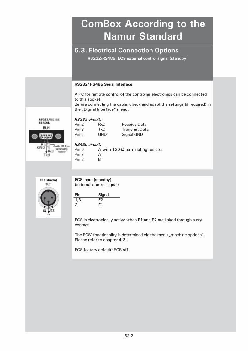
6.3. Electrical Connection Options RS232/RS485, ECS external control signal (standby)
ComBox According to the
Namur Standard
RS232/ RS485 Serial Interface
A PC for remote control of the controller electronics can be connectedto this socket.Before connecting the cable, check and adapt the settings (if required) inthe „Digital Interface“ menu.
RS232 circuit:
Pin 2 RxD Receive DataPin 3 TxD Transmit DataPin 5 GND Signal GND
RS485 circuit:
Pin 6 A with 120 Ω Ω Ω Ω Ω terminating resistorPin 7 APin 8 B
ECS input (standby)
(external control signal)
Pin Signal1,3 E22 E1
ECS is electronically active when E1 and E2 are linked through a drycontact.
The ECS’ fonctionality is determined via the menu „machine options“.Please refer to chapter 4.3..
ECS factory default: ECS off.
63-2
6.3. Electrical Connection Options AIF Analog Interface
Safety Instructions for the ComBox: Never apply mains voltage to the plugconnections of the signal interface! Danger to life!
ComBox According to the
Namur Standard
The analog interface of the ComBox is normaly programmed via the menu„analog Interface“.
The ComBox features 3 analog channels. They are occupied as follows:
1. (1st) actual value: Allways the output of the actual setpoint.
2. (2nd) actual value: Allways the output of the process temperature.
3. (3rd) actual value: The behaviour of this output is programmable (via the controller menu Analog Interface\ Analog
Out).
AnalogSignals
63-3

6.3. Signal Interface Analog Interface (AIF/REG+E-PROG) and POKO (dry contact)
Safety Instructions for the ComBox
Warning: Never apply mains voltage to the plug connections of the signalinterface! Danger to life!
ComBox According to the
Namur Standard
POKO (dry contact) (for external alarm evaluation)
This connection is designed in the form of a potential-free change-overcontact. Pin 2 and Pin 3 are connected in steady state.
Switching current max. 1A at 24V DC
Use shielded cables only!
Programmer input/temperature recorder outputs
AIF/REG+E+PROG
Pin Signal
1 Current output 2nd actual value 0...20 mA2 Current output 1st actual value 0...20 mA3 Gnd for output 0V4 Analog input 0...20 mA5 Current output 3rd actual value 0...20 mA6 Gnd for Analog input 0V
63-4
The POKO (dry contact) shows the status of the thermostat through theposition of the switch. If the normally open contact (n.o.) is closed, theunit will be in working order. In case of disturbance, the n.o. will beopen.

6.3. Digital Interface with Additional
NAMUR Commands RS232-, Command syntax, Namur commands
The ComBox features a digital RS232 interface.According to the NAMUR recommendation (NE28), some commands areset up. The following character notation conditions apply if you usethese Namur commands:
1 Start bit8 character bits1 Stop bit. No parity
The transfer rate is set in the „Digtal Interface“ menu of the controller.
Data flow controller: Commands are not buffered, a new command maybe sent as soon as the response to the topical query has been received.If a response it not to be expected, a break of 500 ms must be made.
Access mode: Master (computer/ PLC) slave (thermostat) procedure.The slave can only be active on request of the master. Guaranteedresponse time: within 500 ms.
IN_PV_00 Query Tintern temperature (jacket)IN_PV_02 Query Textern temperature (reactor inside temperature)IN_SP_00 Query current thermoregulation setpointIN_SP_05 Query current analog setpointOUT_SP_00 Define xxx.xx setpointSTART Activate thermoregulationSTOP Deactivate thermoregulationSTATUS Query device status
STATUS Monadic
-1 AlarmManual Stop 0 OK / standby / manual stopManual Stop 1 OK Temp. or bleedRemote Stop 2 Remote control of active temp. offRemote Start 3 Current temp. with remote control
- Commands and parameters must be separated with a blank- Parameters are submitted with a floating point number or an integer- The full stop is the decimal separator in a floating point number (Code 46).- Following the comma, 2 characters are permissible in OUT commands.- A following physical unit is ignored.- A positive sign can be omitted.- Exponent parameters are not permitted.
More notes
on the
command
syntax
RS232
Commands
Namur
Commands
Safety Instructions for the ComBox
Warning: Never apply mains voltage to the plug connections of the signal
interface! Danger to life!
ComBox According to the
Namur Standard
63-5

6.3. Digital Interface with Additional
NAMUR Commands Command Sequence
Example of a Possible Thermoregulation Task:
Note: the notation \r\n means that CR LF is used as the terminatingcharacter of the command. The characters exchanged via the interfaceare enclosed in „“.
Master Slave Comment
„START\r\n“ Start thermoregulation
„OUT_SP_00 21.20\r\n“ Set setpoint to 21.2 °CSetpoint queried
„IN_PV_00\r\n“ Request Tintern (internaltemperature)
„20.5\r\n“ Slave sends thetemperatures„IN_PV_02\r\n“ Request Textern (externaltemperature)
„20.5\r\n“ Slave sends thetemperatures„STOP\r\n“ Switch off thermoregulation
Note:
If the controller doesn’t answer, a break of 0.5 s must be maintained.
Example
CommandSequence
Safety Instructions for the ComBox
Warning: Never apply mains voltage to the plug connections of the signalinterface! Danger to life!
ComBox According to the
Namur
63-6

64-1
The display shows the alarm message in the form of a „flash“display.In intervals of 2 seconds, the display alternates with the statusdisplay.„Alarm !!!“ is displayed in the upper line of the alarm message.The cause of the alarm is displayed in the bottom line of the alarmmessage.
6. Appendix
6.4. Device Messages
„Device messages“ are codes that inform the user or service technicianof „occurrences“ and the current status of internal components andsystems at the time of the „occurrence“.The controller display’s device messages automaticallyDevice messages can be a warning or a fault.All alarm messages shut down the thermoregulation process.Factory default settings determine that all device messages areaccompanied by an acoustic alarm. (This can be disabled via the„Acoustic Alarm“ option.)
All alarm messages will persist until the cause of the alarm has beenrectified.All alarm messages must be acknowledged via the „Alarm Mode“option.Once the alarm has been acknowledged and the cause of the alarm hasbeen rectified, the alarm message will disappear.
Once the cause of the alarm has been rectified, the thermostat willfunction as programmed.
The following applies to all automatic messages that are identified by the
„Practice“ icon:
Please check the external conditions of your thermostat and your controller
inputs according to the operating instructions and your process arrangement.
If required, re-program the condition.
If the message persists after you have repeated this action, please contact our
Service Hotline.
The following applies to all spontaneous messages that are identified bythe „Hotline“ icon:Please switch off the thermostat and call our Service Hotline
Hotline Germany: (+49)781 – 9603 – 244
Hotline Service Center USA: (+1)740 – 373 – 6809
Hotline Service Center NL: (+31)- 485 – 542 - 811
ALARM !!!
32.0C
To acknowledge the alarm message:Select the „Alarm Mode“ option. Display in Stop Mode (refer to4.3.9) Follow the displayed prompts.
Display in Stop Mode (refer to 4.3.9)Select „Restart“ or „Continue“.
ALARM MODEswitch on and off
ALARM MODEI-> Restart
Continue
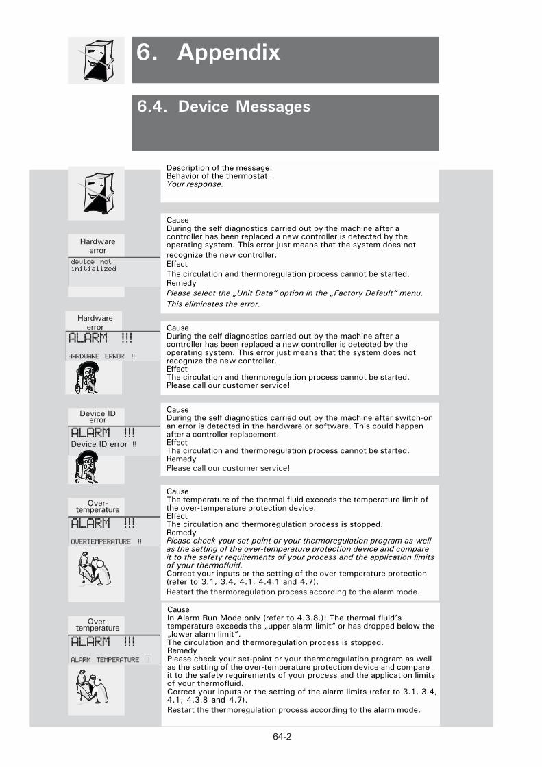
64-2
6.3. Meldungen
6. Anhang6. Appendix
Description of the message.Behavior of the thermostat.Your response.
6.4. Device Messages
Device IDerror
CauseDuring the self diagnostics carried out by the machine after switch-onan error is detected in the hardware or software. This could happenafter a controller replacement.EffectThe circulation and thermoregulation process cannot be started.RemedyPlease call our customer service!
Over-temperature
CauseThe temperature of the thermal fluid exceeds the temperature limit ofthe over-temperature protection device.EffectThe circulation and thermoregulation process is stopped.RemedyPlease check your set-point or your thermoregulation program as wellas the setting of the over-temperature protection device and compareit to the safety requirements of your process and the application limitsof your thermofluid.Correct your inputs or the setting of the over-temperature protection(refer to 3.1, 3.4, 4.1, 4.4.1 and 4.7).
Restart the thermoregulation process according to the alarm mode.
Hardwareerror Cause
During the self diagnostics carried out by the machine after acontroller has been replaced a new controller is detected by theoperating system. This error just means that the system does notrecognize the new controller.EffectThe circulation and thermoregulation process cannot be started.Please call our customer service!
ALARM !!!
HARDWARE ERROR !!
ALARM !!!Device ID error !!
ALARM !!!
OVERTEMPERATURE !!
Hardwareerror
CauseDuring the self diagnostics carried out by the machine after acontroller has been replaced a new controller is detected by theoperating system. This error just means that the system does not
recognize the new controller.Effect
The circulation and thermoregulation process cannot be started.Remedy
Please select the „Unit Data“ option in the „Factory Default“ menu.
This eliminates the error.
device not
initialized
Over-temperature
CauseIn Alarm Run Mode only (refer to 4.3.8.): The thermal fluid’stemperature exceeds the „upper alarm limit“ or has dropped below the„lower alarm limit“.The circulation and thermoregulation process is stopped.RemedyPlease check your set-point or your thermoregulation program as wellas the setting of the over-temperature protection device and compareit to the safety requirements of your process and the application limitsof your thermofluid.Correct your inputs or the setting of the alarm limits (refer to 3.1, 3.4,4.1, 4.3.8 and 4.7).
Restart the thermoregulation process according to the alarm mode.
ALARM !!!
ALARM TEMPERATURE !!

64-3
6.3. Meldungen
6. Anhang6. Appendix
Description of the message.Behavior of the thermostat.Your response.
6.4. Device Messages
CauseThe circulation pump is overloaded and the pump motor hasoverheated.ResultThe circulation and thermoregulation process is stopped.RemedyMake sure that the thermofluid in use is suitable for thetemperature range over which the thermostat is used.The viscosity of the thermofluid must not exceed 50 mm2/s.If required, change the thermal fluid.Once you are sure that the correct thermal fluid is in use orreplaced the thermal fluid with one that is suitable, allow thepump motor to cool and re-start.If the alarm message persists and you are using a suitablethermal fluid, please call our customer service!
ALARM !!!
PUMP MOTOR !!
Level CauseThe level has dropped below minimum allowed thermofluid levelor the circulation pressure of the pump is too low.ResultThe circulation and thermoregulation process is stopped.RemedyPlease check the thermofluid filling level and if necessary,replenish the thermofluid, (refer to 3.4).Restart the thermoregulation process.If the alarm message persists, please check for visible causesof extraordinarily high fluid losses through loose or defectiveconnections, defective tubing, fluid contamination etc. andrectify.If the alarm persists despite your remedial action, pleasecall our customer service!
CauseA general fault has been detected with the motor windingsor an incorrectly rotating 3-phase supply has been detected.(A trained electrician must swap any two phases in the mainsplug to change the direction of rotation of the 3-phase supply)EffectThe circulation and thermoregulation process is stopped.RemedyMake sure that the thermofluid in use is suitable for thetemperature range over which the thermostat is used.The viscosity of the thermofluid must not exceed 50 mm2/s.If required, change the thermal fluid.Check the condition of all circuit breakers and re-set asnecessary.Once you are sure that the correct thermal fluid is in use orreplaced the thermal fluid with one that is suitable, allow thepump motor to cool and re-start.
If the alarm message persists and you are using a suitablethermal fluid, please call our customer service.
ALARM !!!
WT error chain !!
ALARM !!!
LEVEL !!

64-4
6.3. Meldungen
6. Anhang6. Appendix
Description of the message.Behavior of the thermostat.
6.4. Device Messages
Device IDError Cause
External Pt100 sensor is not connected or defective.EffectThe circulation and thermoregulation process cannot be started.RemedyPlease check the connection of your process Pt100 sensorincluding the connecting cable and the sensor itself. If the sensoris defective, replace it with a new one.
Hardwareerror Cause
An internal temperature sensor is not connected or isdefective.EffectThe circulation and thermoregulation process cannot bestarted.Please call our customer service!
ALARM !!!
INTERNAL SENSOR!!
ALARM !!!
EXTERNAL SENSOR!!
Hardwareerror
CauseDuring the self diagnostics carried out by the machine a hardwareor software error has been detected. Thiscan sometimes happenafter fitting a new controller.EffectThe circulation and thermoregulation process cannot be started.RemedyPlease contact our customer service!
ALARM !!!
PCP INIT ERROR !!
L-1
AIF – Analog Interface.The analog interface is
used to transfer constantly changing values,mostly temperatures, in the form of a signalcurrent (generally 4 to 20 mA). Refer to „ExternalControl“! Refer to 4.3!
Alarm LimitThe defined absolute temperature forthe thermofluid or product depending on thecontrol mode.When the temperature exceeds ordrops below the defined value, the thermostatwill respond as defined in the alarm mode.
Alarm ModeThe response of the thermostat when thetemperatureerature has exceeded or droppedbelow the defined alarm limits.
Bath TankAn open tank that holds the thermofluid (fluid forthermoregulation).
Bath, ClosedDouble-wall, closed „shell“ with inflow andoutflow connections.Indirect thermoregulation of the customers’products in the „core“.Designed in metal orglass.Refer to „Reactor“, refer to 3.3!
Bath OpeningThis is the active surface available for directthermoregulation, generally across the entireusable depth.
Bath ThermostatA bath thermostat is a thermostat equipped witha circulation pump (force pump in Polystats) anda bath tank for holding the object to bethermoregulated.The circulation pump is primarilyused for mixing the bath fluid, if required,however, it can also pump the fluid through aclosed external circuit, e.g. when flow watercoolers for cooling heating thermostats areconnected.
Bath Thermostat/CirculatorThermostats with a bath opening large enough toaccommodate objects for direct thermoregulationin the bath, including a circulation pump (force orsuction pump with Compatible Controlthermostats) for closed (force pump) or openexternal (suction pump) circuits.
Bath Volume (also referred to as fill volume)The volume of the thermofluid inside the bath,required for the intended operation of thethermostat, excluding the thermofluid volume inexternal fluid circuits.Especially in closed external applications, theexpansion tank must be dimensioned with caresince the circulator must additionally handle theexpansion of the fluid in the external circuit.
Baud RateThe data transfer rate for serial communication(mandatory setting).Refer to:4.2 Digital Interface!
Automatic Mains Failure Control (Mains FailureAuto)Determines the response of the thermostat in thecase of a power failure.The corresponding settings are made in the mainmenu of the controller.Default setting:Mains Failure Auto is disabled.Once the supply ofpower has been restored, manual intervention isrequired to continue the thermoregulationprocess.Alternative setting:Mains Failure Auto is enabled.Once the supply ofpower has been restored, thermoregulation isautomatically continued.Refer to 4.3!
Ambient Temperature RangeThis is the temperature range permissible in thearea surrounding the device for the device tofunction properly.For all devices by HUBER, this is the temperaturerange from 5 to 30 °C. The cooling performancequoted is always based on an ambienttemperature of 20 °C.
Automatic Cooling Capacity ControlA method for saving energy and resources.Themicroprocessor control determines whether therequired cooling capacity can be reducedaccording to the operating temperature.Theadaptation is performed continuously and – apartform saving energy – it also protects thecompressor, decreases heat dissipation into theenvironment and reduces the consumption ofcooling water.Refer to Compressor Auto, 4.3!
Automatic Compressor Control (CompressorAuto)Supports an energy-saving method for coolingthermostats in specific thermoregulationsituations.A control logic in the microprocessorhelps decide whether the chiller is needed at all orwhether it can be switched off.Refer to 4.2.! Refer to Automatic CoolingCapacity Control!
Actual TemperatureThe temperature at the measuring point at thetime of display.The measuring point is either inthe thermostat, in the thermofluid (factory default:internal thermoregulation) or external to thethermostat, e.g. in the core of a reactor (externalthermoregulation).
Appendix
Huber Glossary

L-2
Characteristic TemperatureThis term denotes the operating temperature of aheating thermostat attained in stationary statuswith the heating switched off and the pump inoperation.It depends on the motor capacity ofthe pump installed, the bath fluid used(viscosity, density) and the thermostatinsulation, e.g. on whether the bath cover isused or not.
Cooler (Special Feature of the Unistat Tango)This type of cooler is a heat exchanger throughwhich water flows during the cooling process.This cooling water leads off just enough heatfrom the superheated refrigerant to preventcondensation.The cooling water may flow only while thecompressor is in operation, otherwise thecooling unit will not work!It is important that only a tiny runnel of coolingwater is routed through the cooler.
CondenserApparatus in chillers for condensing refrigerantvapors
(liquefier).
Cooling CapacityHeat abstraction from the thermofluid via heatexchangers, using either ambient air or coolingwater.Refer to HT-Cooler!
Cooling WaterWater routed through the thermostat via asystem of pipes for cooling the chiller.It shouldcontain only minimized amounts of lime andcorrosive substances that limit the life cycle ofthe system.
Cooling ThermostatA thermostat, the working temperature range ofwhich is generally below the ambienttemperature and that preferably abstracts heatfrom the thermofluid.HUBER cooling thermostatsare actually cooling/heating thermostats sincetheir working temperature ranges from below toabove the ambient temperature and they arecapable of abstracting heat from or transferringheat to the thermofluid.
Cooling/Heating ThermostatA thermostat with a working temperature rangingfrom below to above the ambient temperaturethat is capable of abstracting heat from andtransferring heat to the thermofluid.
Calibration Thermostat (CAL)A bath thermostat with an especially high degreeof temperature stability and especially uniformtemperature distribution across the bath fluid.
CalibrationVerification of the measured values displayedand – if required – recording of the values bywhich the displayed values deviate from theactual temperatures measured.Refer to OffsetCalibration!
Cascade ControlRefer to Process Control!
CompressorA compressor is a machine for compressinggases and vapors.
Cooling Circulators (IC, UC)These are cooling thermostats designed in theform of circulators.Due to their special design(desktop, tower, without a readily accessiblebath), their cooling performance and pumpingcapacities, they constitute a separate devicegroup.
Circulation PumpThe circulation pump is used to circulate thethermofluid in a closed circuit.
Circulator (Unistat)A circulator is a thermostat, in which thethermofluid is routed through an open or closedexternal circuit.Unistats feature a thermicallydecoupled, active surface (expansion tank). Inthis case, however, the surface temperaturediffers from the operating temperature. Unistatsare not equipped with a bath.
Circulation (operating mode)Circulation means that the thermofluid circuit isdriven by the circulation pump.The heater and/orcooling unit are switched off.Refer to 4.6!“Circulation“!
ControllerIn a long tradition at Huber’s, „controller“ refersto an exchangeable electronics unit, includingthe required control and thermoregulationsoftware.Refer to 2.3!
Control Mode – Internal, Process (Cascade)Internal thermoregulation:The temperaturemeasured inside the thermostat (flowtemperature) is used as the controlled variablefor thermoregulation.Process (Cascade):With the
aid of an external Pt100 sensor, a measuring
point outside the thermostat in an external
application, e.g. in a reactor, is used for
controlling the thermoregulation process.
Refer to:4.4!
Appendix
Huber Glossary

L-3
FLRefer to Safety Classification!
Delivery PressureThe overpressure of the circulation pump of athermostat directly at the pressure connectingpiece, measured using water.On charts, thedelivery pressure is expressed as a function ofthe flow rate.
Delivery SuctionThe suction of the circulation pump (force/suction pump or duplex pump) directly at thepressure connecting piece, measured usingwater.On charts, the delivery suction isexpressed as a function of the flow rate.
Flow RateThe volume of fluid delivered by the circulationpump per time unit, measured using water.Incharts, the flow rate is expressed as a functionof the delivery pressure (backpressure).
Fill VolumeRefer to Bath Volume!
Effective Heating CapacityHeat flow delivered to the thermofluid (fluid forthermoregulation) by heat sources.
Digital InterfaceThe digital interface is used to transfer data inthe form of bits and bytes.
DW-ThermDW-Therm is a thermofluid (fluid forthermoregulation) developed especially forUnistats (Huber thermostats with a closedthermofluid circuit) with an extremely largetemperature range (-90°C...+200°C).
External ControlThe thermostat is not controlled through thecontroller but rather through external equipment.The external interface (multifunction socket) onthe Polystat controller is used for this purpose.Refer to:2.3, 4.3!
Default Parameters
Refer to Factory Default!
Extended Working Temperature RangeThis is the working temperature range extendedto lower temperature levels achieved through theuse of a manufacturer-defined cooling coil withcooling water.
Force/Suction PumpThis pump features a pressure and a suctionstage driven by a common motor.The pressurestage forces the thermofluid from the thermostatinto the circuit, the suction stage draws the fluidback into the thermostat.A force/suction pumpcan be used in a closed circuit.Benefit:In theexternal circuit, the pressure drops from positivevalues (pressure) to negative values (vacuum)and is almost zero in the consumer.Thisfacilitates thermoregulation even of pressure-sensitive glass vessels.In addition, an openexternal circuit (bath tank) can also be connectedusing a force/suction pump.A level constantensures a constant fluid level in the bath tank.
Flash PointThe term flash point denotes the temperature towhich a fluid in an open bath must be heateduntil the vapor/air mixture at the surface inflameswhen a flame is held near and keeps on burningonce the flame is pulled away again.Refer to:3.1.EN 61010-1EN 61010-1
Force PumpThe force pump is used for circulating thethermofluid in a closed external circuit and formixing the fluid inside the bath.
Flow Cooler (DC)Flow coolers are „uncontrolled“ coolers withoutcirculation pump that are interposed in anexternal circuit, thus expanding the functionalityof a heating thermostat to that of a heating/cooling thermostat.On the one hand, theysubstitute water cooling, on the other hand theyare used to achieve lower temperatures.
Flash DisplayController display shown for seconds only toprovide information on a variable intermediateprogram status or the status of the thermostat.
Flow TemperatureDenotes the temperature measured directly at thepoint the thermofluid exits the circulator.
Factory DefaultThe manufacturer has set the thermostatparameters such that the temperature rangeconstitutes only a minimum potential hazard andthat the easiest and most probablethermoregulation process can be performed.Factory defaults ensure safe commissioning bythe customer and can be changed using therespective programs according to therequirements of the customerAll the factory defaults can be restored withProgram 52 with the thermoregulation functionswitched off.Refer to 4.2 Restart!
Appendix
Huber Glossary

L-4
Medium Temperature Stage (MT)
Refer to High Temperature Stage!
NFL
Refer to Safety Classification!
Low Temperature Stage (NT)Refer to High Temperature Stage!
Gas VentingA special thermoregulation regime common toall Unistats with the objective of perpetuatingthermoregulation despite the evaporation ofpart of the thermofluid and removing elementswith a low boiling point from the circulatingfluid.
Housing VolumeThe volume resulting from the outer dimensionsof the thermostat.
Heating CapacityThe maximum installed electrical power of theheating element.The heating capacity dependson the voltage of the thermostat. It iscontinuously controlled and reduced when thetemperature approaches the programmedsetpoint.
High-Pressure Cut-OutProtective switch installed in Unistats andUnichillers. Shuts down the thermoregulationprocess if the pressure on the compressor sidegets too high.Applies to Unistats:Once the Unistat is ready foroperation again, the high-pressure cut-out mustbe pressed to continue the thermoregulationprocess.Applies to Unichillers:Once the Unichiller isready for operation again, the high-pressure cut-out is automatically reset to continue thethermoregulation process.(The high-pressurecut-out in Unichillers is not readily accessible.)
High-Temperature Cooler (with Unistats):A high-temperature cooler is a heat exchangerthat cools a thermofluid from a high temperatureto ambient temperature using air or water.It isinstalled on the upstream side of chillers inUnistats, thus reducing the load on and powerconsumption of the chiller.
High Temperature Stage (HT) (with Unistats):The high temperature stage is the toptemperature stage in multi-stage chillers inUnistats.Sie dient der It is used for decreasingthe temperature (to approx. –60 °C) and thusprepares the low temperature stage (NT) in dual-stage chillers (to approx. –90 °C) and themedium temperature stage (MT) (to approx.–90 °C) in triple-stage chillers.The medium temperature stage, in turn, preparesthe low temperature stage (currently to approx.–120°C) in triple-stage chillers.
Heat Exchanger
Refer to Thermofluid!
Heating ThermostatA thermostat, the working temperature range ofwhich is primarily above the ambienttemperature and that preferably transfers heat tothe thermofluid.
Immersion Thermostat (Polystats cc)This is a thermostat that is combined with abath tank that forms an independent unit.Immersion thermostats are equipped with ascrew clamp for fastening to the walls of anydesired bath tank. Using a bath bridge, they canalso be mounted permanently on the top of abath or on a tripod.
Immersion Cooler (TC)A cooling unit with a flexible tube and a coolingcoil (evaporator) for immersing in baths.
Industrial Thermostats (IC-Hx)Industrial thermostats are cooling circulators(intelligent chillers) with a heater installed exworks.High cooling, heating and pumpingcapacities and small fluid volumes provide forfast cooling and heating rates.They are ideal forthermoregulation in process engineering and innarrow temperature ranges (-20..120 °C).
Interface, DigitalThis interface is used for digital data exchangebetween connected devices via the datacommunication line.Primarily, the temperaturesetpoint and the actual temperature aretransmitted.Refer to:RS232 Interface and RS485Interface!Refer to:4.3 Main Menu, Digital Interface!
Interface, Analog (AIF)This interface is used for entering thetemperature setpoint or for the output of theactual temperature as an analog value in theform of a signal current (4 – 20 mA).Refer to:4.3 Main Menu, Analog Interface!
Net Refrigerating CapacityThe effective capacity the cooling thermostat orchiller provides for the application.The frictionalheat generated by the circulation pump and theheat entering due to insufficient insulation hasalready been taken into consideration.Thecooling capacity data correspond to those of thenet cooling capacity.
Appendix
Huber Glossary
L-5
Physical MassThe physical mass describes the P/I parameters(P=proportional, I=integral) of the thermostat.Refer to 4.3!
Offset CalibrationSingle-point correction of a temperature sensorat a specific temperature.
Overheat PointRefer to Overtemperature Protection!
POKO Potential-Free ContactThe POKO is a change-over contact led throughthe POKO relay in the controller.The potential-free contact is designed for an ohm resistiveload up to 30 V and a maximum of 0.1 A.The following applies due to the working currentprinciple:The OK status is linked to the flow ofcurrent through the winding of the POKOrelay.The POKO relay is actuated by thecontroller.
Program (Thermostat Control)The controller provides programs for the user tooperate the thermostat, to monitor and controlstatuses and processes, i.e. to perform thethermoregulation process.
Program (Thermoregulation)
Refer to Thermoregulation Program!
Process Temperature (core temperature)The process temperature is the temperaturemeasured in the core of a connected externalapplication (in the case of externalthermoregulation), e.g. in the core of areactor.Refer to Reactor, Control Mode!Refer to 2.3!
Operating Temperature RangeThis is the temperature range that is limited bythe permissible minimum and maximumoperating temperature.The operating temperature is the temperature towhich the thermostat is permitted to heat/coolthe respective thermofluid.
Overtemperature ProtectionEach thermostat with a heater is equipped withovertemperature protection.The overtemperatureprotection operates completely independently ofthe controller, i.e. it cannot be influencedthrough the controller.If at least one temperaturesensor reports that a temperature limit has beenexceeded, the thermoregulation process isstopped at once.In the course of the thermoregulation process,the sensors are tested for short-circuit andfailure.The overtemperature protection isequipped with an independent protectivedevice.This prevents very reliably that the OKstatus is set while there actually is a failure.Theuser sets the upper temperature limit(overheating point) at the thermostat to ensureoperating safety considering the respectivethermofluid used.For unattended operation, theoverheating point must be selected at least at 25°C below the flash point of the respectivethermofluid.Refer to:4.1.!
OverheatingThe positive difference between thecondensation temperature and the topical gastemperature of the thermofluid in therefrigeration process.(Does not refer tooverheating of the thermostat!)
Presettings ex Works, Factory DefaultRefer to Factory Default!
PLC (Programmable Logic Controller)A device frequently used in industrialenvironments to control operations andprocesses.
Process Control (often referred to as cascadecontrol)Thermoregulation of a connected application.Atemperature sensor (Pt100) that forms part ofthis application is connected with thethermostat.The actual temperature of theexternal process is sensed and the operatingtemperature of the thermostat is permanentlycalculated and adapted.Depending on theoperating temperature, losses through insulationand exothermic reactions, the operatingtemperature at the consumer may deviateconsiderably from the setpoint and the actualtemperature of the application.Caution!Observe the safety-relevant limits of therespective thermofluid!Refer to: 3.1!
Appendix
Huber Glossary

L-6
RS232 InterfaceDigital controller interface for digital dataexchange between connected devices via thedata communication line.RS232 is a serialinterface for establishing a point-to-pointconnection.This means, only two parties, e.g. athermostat and a PC, can communicate via theinterface at a time.Refer to:4.3. Main Menu, Digital Interface!
RS 485 InterfaceDigital controller interface for digital dataexchange between connected devices via thedata communication line.As many as 32 parties can be connected to theRS 485 interface.Each party connected to thisbus system is assigned a separate address.Refer to:4.3 Main Menu, Digital Interface!
SegmentA segment is a section of a thermoregulationprogram that creates part of the temperaturegraph.Refer to Thermoregulation Program!
Self TestTest procedure in the thermostat after poweron.It ensures the operability of safety-relevantthermostat components.(Except for overtemperature protection!)
Safety ClassificatioIn thermostats, either flammable (FL) or non-flammable (NFL) thermofluids (fluids forthermoregulation) may be used.The respectivesafety requirements have been laid down in DINEN 61010-2-010.Accordingly, the safetyclasses NFL and FL have been defined:NFL (non-flammable) thermostats with integratedoverheating protection exclusively for non-flammable fluids.Thermostats classified as FL (flammable) withadjustable overtemperature protection and lowliquid level protection for flammable fluids (allthe thermostats by HUBER).Refer to: 3.1.Thermofluid!
SetpointThe temperature to be attained at the point ofmeasurement.Maximum SetpointThe highest permissible temperature to beattained at the point of measurement.Minimum Setpoint
The lowest permissible temperature to beattained at the point of measurement.Refer to Control Mode!
Refer to 4.4!
Remote Control PanelAn external device permitting operation of theHuber Thermostat (possibly to a limited extent).
ReactorA cylindrical double-wall tank permitting theflow of thermofluid through the space betweenthe two walls (jacket).The temperature of thethermofluid is transferred to the hollow spaceinside (core) via the inner wall.The user fills his/her reagents into this core with separate inletsand outlets.The reagents are then indirectlythermoregulated via the inside reactor wall.
Refrigerating CapacityHeat flow led off from the thermofluid by acooling thermostat.
RefrigerantRefrigerant is used in the circuit of therefrigerating unit. It abstracts heat from thethermofluid when the compressed gas expandsand evaporates in the evaporator.Since 1992HUBER has been using exclusively refrigerantsfree of CFC and since 1994 even refrigerantsfree of HCFC (e.g. R22) that do not harm theozone layer, i.e. with an ODP (Ozone DepletionPotential) = 0 and minimized GWP (GlobalWarming Potential, e.g. greenhouse effect).
RampA desired change in temperature within a giventime period.A ramp is a simple and frequentlyused programming of a temperature pattern.A ramp is defined through the increase intemperature and the thermoregulationperiod.Once the ramp has been entered, thethermoregulation process thus programmed willstart automatically and does not require anyaccompanying inputs.The ramp can be defined through differentcombinations and sequences of the setpoint,time period and slope parameters.Where:Time period = slope x setpointRefer to 4.3!
ProtocolsProtocols are used in digital data exchange.Theterm protocol in this context refers to a series ofrules drawn up to facilitate uniform coding anddecoding of the bits and bytes in the dataexchange between the thermostats and a PC,PCS (process control system) or the like. For thetime being, three protocols are available, two ofwhich have been implemented in all the productfamilies.PPP – point-to-point protocolLAI protocol – for communication on the busThe third protocol is currently only available forUNISTATS on demand:Modbus protocol (Modbus RTU by Gould)
Appendix
Huber Glossary

L-7
Temperature – internal, externalRefer to Control Mode, Flow Temperature!
Temperature StabilityThis term denotes half the difference intemperature between the highest and lowesttemperature measured in a thermostat within 30minutes of attaining a stable value at a specificsetpoint.This value is determined at a temperature of 70°C (with water) for a heating thermostat and at– 10 °C (with ethanol) for a cooling thermostat.Also refer to DIN 12876!
Temperature-StableRefer to Thermoregulation, Temperature-Stable!
Thermoregulation FluidRefer to Thermofluid!
Thermoregulation ProgramArrangement of segments to create areproducible temperature graph.A thermoregulation program is made up of aprogram header and segments.The program header is independent of thenumber of active segments and the length of theprogram.The program header defines the beginning andsequence of the thermoregulation program (TP)through the following parameters:Start temperature of segment n, start ramp slope(K/min),thermoregulation priority: temperature-stable ortime stable, program end.A segment is defined through the followingparameters:Start temperature of segment n (= endtemperature of segment n-1)Segment period nRefer to:4.4!
ThermoregulationThe active manipulation of the temperature of asubstance to the desired level by way of heatingand/or cooling
Thermoregulation, Temperature-Stable!Thermoregulation will proceed until thedefined setpoint has been attained (if required,the desired thermoregulation period will beexceeded).Thermoregulation, Time-StableThermoregulation will proceed according to thetime targets entered (independent of theactual temperature value attained).
TempmovePossibility of selecting the input variable for atemperature.
Thermofluid (fluid for thermoregulation)Heat transfer fluid. Transfers energy from thethermostat to the application or vice versa.Siehe3.1.!Refer to 3.1!
Status DisplayDisplay on the UniCop that provides informationon the topical program sequence or the topicalstatus of the thermostat.
StandardsSafety requirements for electrical laboratoryequipment, and especially for thermostats, havebeen laid down in European Standards EN61010-1 and EN 61010-2-010.Thesestandards replace DIN 12879 (amongothers).The terms and characteristic data aredefined in DIN 12876-1 and DIN 12876-2.
Slave AddressIdentification number the user assigns to adevice to be able to allocate data to a deviceduring data transfer via a bus protocol.Refer to RS485 Interface!
Transparent BathA bath thermostat with transparent wallspermitting direct monitoring of the object to bethermoregulated (Polystat models A5 – A18).
Appendix
Huber Glossary

L-8
WarningDevice messages pointing to irregularities in theoperation of the thermostat that do not cause ashut-down of the thermoregulation process.Programs 10, 11.
WatchdogA safety device in the electronic control, similarto the principle of the dead-man switch in anengineThe functionality of the system ismonitored through the input signals.
Working Temperature RangeThe working temperature range is defined withreference to an ambient temperature of 20 °C. Itdenotes the temperature range the thermostatattains by itself without the aid of any auxiliarymeans*, utilizing electric power only.Due to the heat transferred by the pump motorand the insulation, the working temperature rangeof heating thermostats starts above the ambienttemperature and ends at the upper limit of theoperating temperature.In the case of cooling/heating thermostats, theworking temperature ranges from the lower limitof the operating temperature to the upper limit ofthe operating temperature. This temperature ispermissible in continuous operation with the useof a chiller.The working temperature range of coolingthermostats starts at the lower limit of theoperating temperature and ends at ambienttemperature.*Auxiliary means are additionalheating elements, coolers, heat exchangers orfans.
VentingA special circulation regime with the objective ofdriving out air trapped in closed thermofluidcircuits.
ViscosityAlso referred to as „internal friction“. Thecharacteristic of a fluid or gaseous substancethat causes frictional tension at deformation inaddition to the thermodynamic pressure, whichcounteracts the displacement of fluid or gaseousparticles relative to each other.This means, the viscosity of a substanceincreases with decreasing temperature, theavailable cooling capacity decreases withdecreasing temperature.The viscosity of thermofluids (fluids forthermoregulation) used in HUBER thermostatsshould not exceed 50 mm2/s.
Usable DepthThe term usable depth denotes the depth of fluidavailable in the bath thermostat for directthermoregulation.
Appendix
Huber Glossary