the watter buddy®
TRANSCRIPT

The Watter Buddy®
HV
Owner’s Manual
Please Read Carefully
Made in North America
By
PO Box 4557
Sussex NB
Canada E4E 5L7
Phone +1 (506) 433-3151
Fax +1 (506) 433-6151
Email: [email protected]
Website: www.microhydropower.com
Watter Buddy is a Trademark of Energy Systems & Design Ltd.
V2.0 3-2017

2
Congratulations on your purchase of a new Watter Buddy®.
May your RE adventures prove successful!
Table of Contents
Introduction .............................................................................................. 3-4
Site Evaluation ......................................................................................... 4
Head Measurement .................................................................................. 5
Flow Measurement................................................................................... 5-6
Watter Buddy Output in Watts Table ....................................................... 7
Watter Buddy Head and Flow Rate Table ............................................... 7
Intake, Pipeline & Tailrace ...................................................................... 7-9
Batteries, Inverters & Controllers ............................................................ 9
Wiring and Load Center........................................................................... 10
High and Low Range, Measuring Output ................................................ 11
High Voltage ........................................................................................... 12
Determining Nozzle Size ......................................................................... 12
Bearing Replacement .............................................................................. 13
Installation Examples……………………………………………...…….13
Copper Wire Resistance Chart ................................................................ 13
Pipe Friction Head Loss Charts .............................................................. 14-15
3
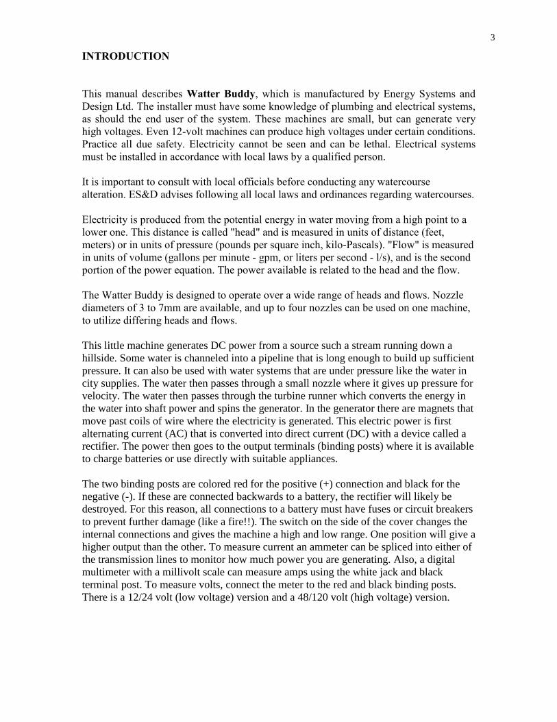
INTRODUCTION
This manual describes Watter Buddy, which is manufactured by Energy Systems and
Design Ltd. The installer must have some knowledge of plumbing and electrical systems,
as should the end user of the system. These machines are small, but can generate very
high voltages. Even 12-volt machines can produce high voltages under certain conditions.
Practice all due safety. Electricity cannot be seen and can be lethal. Electrical systems
must be installed in accordance with local laws by a qualified person.
It is important to consult with local officials before conducting any watercourse
alteration. ES&D advises following all local laws and ordinances regarding watercourses.
Electricity is produced from the potential energy in water moving from a high point to a
lower one. This distance is called "head" and is measured in units of distance (feet,
meters) or in units of pressure (pounds per square inch, kilo-Pascals). "Flow" is measured
in units of volume (gallons per minute - gpm, or liters per second - l/s), and is the second
portion of the power equation. The power available is related to the head and the flow.
The Watter Buddy is designed to operate over a wide range of heads and flows. Nozzle
diameters of 3 to 7mm are available, and up to four nozzles can be used on one machine,
to utilize differing heads and flows.
This little machine generates DC power from a source such a stream running down a
hillside. Some water is channeled into a pipeline that is long enough to build up sufficient
pressure. It can also be used with water systems that are under pressure like the water in
city supplies. The water then passes through a small nozzle where it gives up pressure for
velocity. The water then passes through the turbine runner which converts the energy in
the water into shaft power and spins the generator. In the generator there are magnets that
move past coils of wire where the electricity is generated. This electric power is first
alternating current (AC) that is converted into direct current (DC) with a device called a
rectifier. The power then goes to the output terminals (binding posts) where it is available
to charge batteries or use directly with suitable appliances.
The two binding posts are colored red for the positive (+) connection and black for the
negative (-). If these are connected backwards to a battery, the rectifier will likely be
destroyed. For this reason, all connections to a battery must have fuses or circuit breakers
to prevent further damage (like a fire!!). The switch on the side of the cover changes the
internal connections and gives the machine a high and low range. One position will give a
higher output than the other. To measure current an ammeter can be spliced into either of
the transmission lines to monitor how much power you are generating. Also, a digital
multimeter with a millivolt scale can measure amps using the white jack and black
terminal post. To measure volts, connect the meter to the red and black binding posts.
There is a 12/24 volt (low voltage) version and a 48/120 volt (high voltage) version.

4
Brass nozzles are supplied with the machine in sizes from 3-7 mm. A range of sizes is
provided so that you can match the flow rate (l/s or gpm) of your source. Higher head
(pressure) sources can use smaller nozzles and pass the same flow as larger nozzles at a
lower head. The brass fitting on the machine is made to have the nozzles on the inside
end and the inlet pipe connection on the outer end. This fitting has ½” pipe threads on the
outer end for use with threaded type plumbing, and a plastic adapter is supplied that fits
¾” plastic pipe if you wish to use that. Access to the inner end of this fitting can be
gained by threading the nozzle holder from the housing. The machines can be supplied
with 1 to 4 nozzles installed in the housing.
Flexible lines work best to make the connection at the machine. One arrangement is to
install a stop valve upstream of the flex line and then a pressure gauge upstream of that.
This enables you to determine the pressure when there is no flow (static or gross head)
and when the machine is operating and the stop valve is open (net or dynamic head).
These readings can also tell you when there are problems with the water supply. A lower
than usual pressure with the valve closed tells you that there is air in the pipeline and you
are running out of water or the intake is clogged. If the pressure is lower than normal
when the valve is open it indicates that the problem is upstream. If it is higher, the
problem is downstream and is usually a clogged nozzle. Many water sources wash down
leaves, twigs, grit and other things that conspire to keep you alert. The intake box of the
pipeline should be constructed with a suitable size mesh to filter the water and prevent
debris in the water line.
SITE EVALUATION
Certain information must be determined concerning your site, in order to use its potential
for maximum output. Head and flow must first be determined. Other factors are: pipeline
length, transmission distance, and the system voltage. These factors determine how much
power can be expected.
Power is generated at a constant rate by the Watter Buddy and can be stored in batteries
as direct current (DC). Power is supplied, as needed, by the batteries, which store energy
during periods of low consumption for use in periods where consumption exceeds the
generation rate. Appliances can be used that operate directly from batteries, or 120 volt
alternating current (AC) power can be supplied through an inverter, converting DC to AC
power.
Sites may vary, so carefully consider flow and head when choosing yours. Remember,
maximum head can be achieved by placing the Watter Buddy at as low an elevation as
possible, but going too low may cause the machine to become submerged (or washed
away!).

4
5
HEAD MEASUREMENT
Head may be measured using various techniques. A garden hose or length of pipe can be
submerged with one end upstream and the other end downstream. Anchor the upstream
end with rocks or have an assistant hold it; water should flow out the low end, especially
if the pipeline is pre-filled. Once water is flowing, raise the downstream end until it stops.
Do this slowly since the water tends to oscillate. When the flow has stabilized, measure
the distance down to the level of water in the stream with a tape measure. This will give a
very accurate measurement of that stream section. Mark the spot and then repeat the
procedure until the entire distance is covered.
Another technique is to use a surveyor's transit. This method can also be approximated
using a carpenter's level along with a measuring stick or a "story pole." This technique is
also done in a series of steps to arrive at the overall head. A variation on this method is
the use of altimeters. GPS equipment could also be used to measure elevation.
FLOW MEASUREMENT
The easiest method to measure small flows is to channel the water into a pipe using a
temporary dam and to fill a container of known volume. Measuring the time to fill the
container enables you to calculate the flow rate.
The weir method can also be used to measure flow.
6
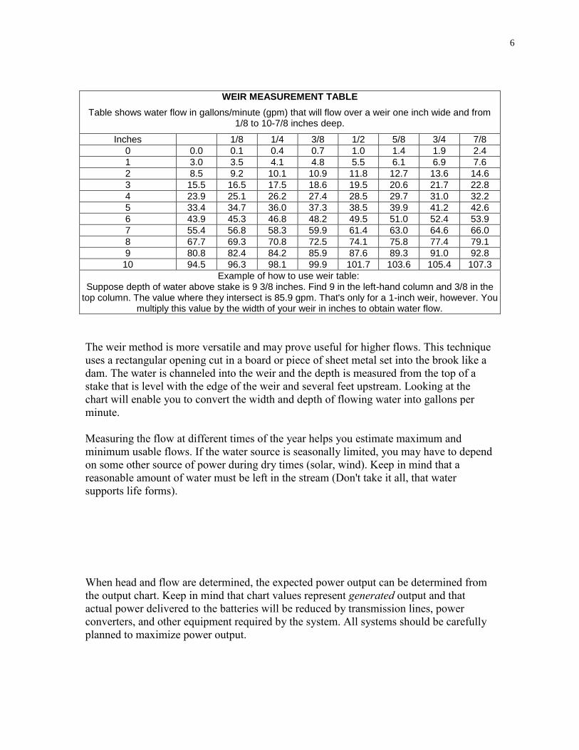
WEIR MEASUREMENT TABLE
Table shows water flow in gallons/minute (gpm) that will flow over a weir one inch wide and from 1/8 to 10-7/8 inches deep.
Inches 1/8 1/4 3/8 1/2 5/8 3/4 7/8
0 0.0 0.1 0.4 0.7 1.0 1.4 1.9 2.4
1 3.0 3.5 4.1 4.8 5.5 6.1 6.9 7.6
2 8.5 9.2 10.1 10.9 11.8 12.7 13.6 14.6
3 15.5 16.5 17.5 18.6 19.5 20.6 21.7 22.8
4 23.9 25.1 26.2 27.4 28.5 29.7 31.0 32.2
5 33.4 34.7 36.0 37.3 38.5 39.9 41.2 42.6
6 43.9 45.3 46.8 48.2 49.5 51.0 52.4 53.9
7 55.4 56.8 58.3 59.9 61.4 63.0 64.6 66.0
8 67.7 69.3 70.8 72.5 74.1 75.8 77.4 79.1
9 80.8 82.4 84.2 85.9 87.6 89.3 91.0 92.8
10 94.5 96.3 98.1 99.9 101.7 103.6 105.4 107.3
Example of how to use weir table: Suppose depth of water above stake is 9 3/8 inches. Find 9 in the left-hand column and 3/8 in the
top column. The value where they intersect is 85.9 gpm. That's only for a 1-inch weir, however. You multiply this value by the width of your weir in inches to obtain water flow.
The weir method is more versatile and may prove useful for higher flows. This technique
uses a rectangular opening cut in a board or piece of sheet metal set into the brook like a
dam. The water is channeled into the weir and the depth is measured from the top of a
stake that is level with the edge of the weir and several feet upstream. Looking at the
chart will enable you to convert the width and depth of flowing water into gallons per
minute.
Measuring the flow at different times of the year helps you estimate maximum and
minimum usable flows. If the water source is seasonally limited, you may have to depend
on some other source of power during dry times (solar, wind). Keep in mind that a
reasonable amount of water must be left in the stream (Don't take it all, that water
supports life forms).
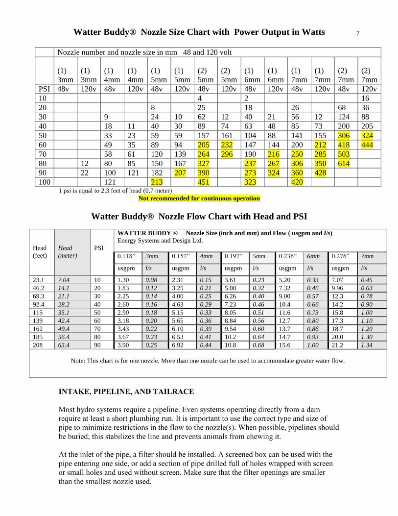
When head and flow are determined, the expected power output can be determined from
the output chart. Keep in mind that chart values represent generated output and that
actual power delivered to the batteries will be reduced by transmission lines, power
converters, and other equipment required by the system. All systems should be carefully
planned to maximize power output.
7
Watter Buddy® Nozzle Size Chart with Power Output in Watts
Nozzle number and nozzle size in mm 48 and 120 volt
(1)
3mm
(1)
3mm
(1)
4mm
(1)
4mm
(1)
5mm
(1)
5mm
(2)
5mm
(2)
5mm
(1)
6mm
(1)
6mm
(1)
7mm
(1)
7mm
(2)
7mm
(2)
7mm
PSI 48v 120v 48v 120v 48v 120v 48v 120v 48v 120v 48v 120v 48v 120v
10 4 2 16
20 8 25 18 26 68 36
30 9 24 10 62 12 40 21 56 12 124 88
40 18 11 40 30 89 74 63 48 85 73 200 205
50 33 23 59 59 157 161 104 88 141 155 306 324
60 49 35 89 94 205 232 147 144 200 212 418 444
70 58 61 120 139 264 296 190 216 250 285 503
80 12 80 85 150 167 327 237 267 306 350 614
90 22 100 121 182 207 390 273 324 360 428
100 121 213 451 323 420 1 psi is equal to 2.3 feet of head (0.7 meter)
Not recommended for continuous operation
Watter Buddy® Nozzle Flow Chart with Head and PSI
Head
(feet)
Head
(meter)
PSI
WATTER BUDDY ® Nozzle Size (inch and mm) and Flow ( usgpm and l/s)
Energy Systems and Design Ltd.
0.118” 3mm 0.157” 4mm 0.197” 5mm 0.236” 6mm 0.276” 7mm
usgpm l/s usgpm l/s usgpm l/s usgpm l/s usgpm l/s
23.1 7.04 10 1.30 0.08 2.31 0.15 3.61 0.23 5.20 0.33 7.07 0.45
46.2 14.1 20 1.83 0.12 3.25 0.21 5.08 0.32 7.32 0.46 9.96 0.63
69.3 21.1 30 2.25 0.14 4.00 0.25 6.26 0.40 9.00 0.57 12.3 0.78
92.4 28.2 40 2.60 0.16 4.63 0.29 7.23 0.46 10.4 0.66 14.2 0.90
115 35.1 50 2.90 0.18 5.15 0.33 8.05 0.51 11.6 0.73 15.8 1.00
139 42.4 60 3.18 0.20 5.65 0.36 8.84 0.56 12.7 0.80 17.3 1.10
162 49.4 70 3.43 0.22 6.10 0.39 9.54 0.60 13.7 0.86 18.7 1.20
185 56.4 80 3.67 0.23 6.53 0.41 10.2 0.64 14.7 0.93 20.0 1.30
208 63.4 90 3.90 0.25 6.92 0.44 10.8 0.68 15.6 1.00 21.2 1.34
Note: This chart is for one nozzle. More than one nozzle can be used to accommodate greater water flow.
INTAKE, PIPELINE, AND TAILRACE
Most hydro systems require a pipeline. Even systems operating directly from a dam
require at least a short plumbing run. It is important to use the correct type and size of
pipe to minimize restrictions in the flow to the nozzle(s). When possible, pipelines should
be buried; this stabilizes the line and prevents animals from chewing it.
At the inlet of the pipe, a filter should be installed. A screened box can be used with the
pipe entering one side, or add a section of pipe drilled full of holes wrapped with screen
or small holes and used without screen. Make sure that the filter openings are smaller
than the smallest nozzle used.

8
The intake must be above the streambed so as not to suck in silt and should be deep
enough so as not to suck in air. The intake structure should be placed to one side of the
main flow of the stream so that the force of the flowing water and its debris bypasses it.
Routinely clean the intake of any leaves or other debris.
If the whole pipeline doesn't run continuously downhill, at least the first section should,
so the water can begin flowing. A bypass valve may be necessary. This should be
installed at a low point in the pipe.
For pipelines running over dams, or in conditions that create a siphon, the downstream
side may be filled by hand. Once filled, the stop valve at the turbine can be opened to
start the flow. If full pressure is not developed, or air builds up in the line, a hand-
powered vacuum pump can be used to remove air trapped at the high point.
At the turbine end of the pipeline a bypass valve may be necessary to allow water to run
through the pipe without affecting the turbine, purging the line of air or increasing flow to
prevent freezing.
A stop valve should be installed upstream of the nozzle. A pressure gauge should be
installed upstream of the stop valve so both the static head (no water flowing) and the
dynamic head (water flowing) can be read.
The stop valve on a pipeline should always be closed slowly to prevent water hammer
(the column of water in the pipe coming to an abrupt stop). This can easily destroy your
pipeline and for this reason, you may wish to install a pressure relief valve just upstream
of the stop valve. This can also occur if debris clogs the nozzle. In a single nozzle
machine a nozzle that becomes clogged suddenly may create water hammer. The use of
flexible pipe makes it easier to remove the plumbing from the nozzles.
9
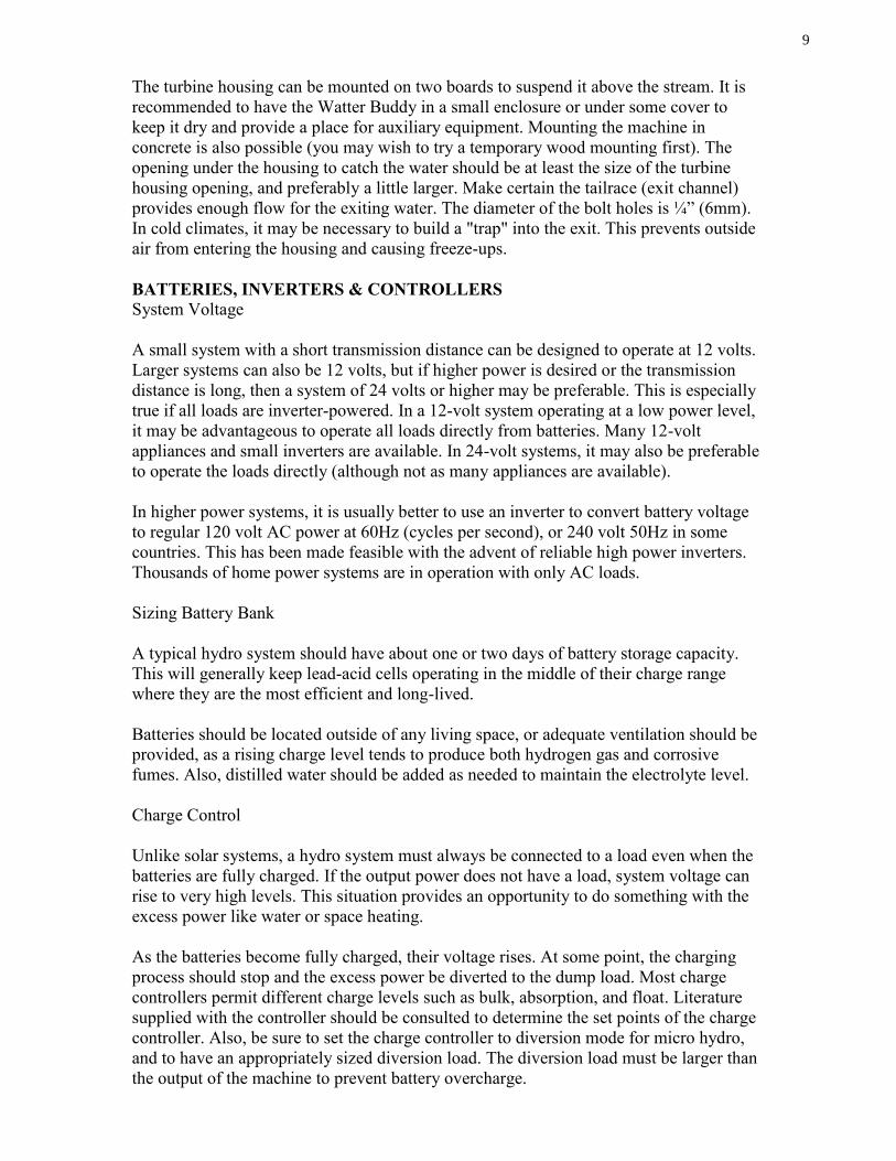
The turbine housing can be mounted on two boards to suspend it above the stream. It is
recommended to have the Watter Buddy in a small enclosure or under some cover to
keep it dry and provide a place for auxiliary equipment. Mounting the machine in
concrete is also possible (you may wish to try a temporary wood mounting first). The
opening under the housing to catch the water should be at least the size of the turbine
housing opening, and preferably a little larger. Make certain the tailrace (exit channel)
provides enough flow for the exiting water. The diameter of the bolt holes is ¼” (6mm).
In cold climates, it may be necessary to build a "trap" into the exit. This prevents outside
air from entering the housing and causing freeze-ups.
BATTERIES, INVERTERS & CONTROLLERS
System Voltage
A small system with a short transmission distance can be designed to operate at 12 volts.
Larger systems can also be 12 volts, but if higher power is desired or the transmission
distance is long, then a system of 24 volts or higher may be preferable. This is especially
true if all loads are inverter-powered. In a 12-volt system operating at a low power level,
it may be advantageous to operate all loads directly from batteries. Many 12-volt
appliances and small inverters are available. In 24-volt systems, it may also be preferable
to operate the loads directly (although not as many appliances are available).
In higher power systems, it is usually better to use an inverter to convert battery voltage
to regular 120 volt AC power at 60Hz (cycles per second), or 240 volt 50Hz in some
countries. This has been made feasible with the advent of reliable high power inverters.
Thousands of home power systems are in operation with only AC loads.
Sizing Battery Bank
A typical hydro system should have about one or two days of battery storage capacity.
This will generally keep lead-acid cells operating in the middle of their charge range
where they are the most efficient and long-lived.
Batteries should be located outside of any living space, or adequate ventilation should be
provided, as a rising charge level tends to produce both hydrogen gas and corrosive
fumes. Also, distilled water should be added as needed to maintain the electrolyte level.
Charge Control
Unlike solar systems, a hydro system must always be connected to a load even when the
batteries are fully charged. If the output power does not have a load, system voltage can
rise to very high levels. This situation provides an opportunity to do something with the
excess power like water or space heating.
As the batteries become fully charged, their voltage rises. At some point, the charging
process should stop and the excess power be diverted to the dump load. Most charge
controllers permit different charge levels such as bulk, absorption, and float. Literature
supplied with the controller should be consulted to determine the set points of the charge
controller. Also, be sure to set the charge controller to diversion mode for micro hydro,
and to have an appropriately sized diversion load. The diversion load must be larger than
the output of the machine to prevent battery overcharge.

10
Watt-Hour meters are available that monitor the battery state of charge.
An ammeter that monitors turbine output should always be installed in a high traffic or
living space so difficulties with the machine can be easily detected. If a drop in output is
noticed, the machine should be inspected. This could be caused by air in the pipeline, or a
blocked or partially blocked nozzle. More importantly, a drop in output could be the
beginning of bearing failure. Bearing failure will cause serious damage to the machine.
Early detection of problems with the bearings is vital.
WIRING AND LOAD CENTER
Every system requires wiring to connect the various components. Load centers are
available as a complete package that easily facilitates the connection of loads and power
source(s). All circuits in the system should use wire of adequate size and have fuses or
breakers of sufficient capacity to carry the expected load current. The Watter Buddy must
be fused in a battery system since it can suffer from a short or similar fault just like
anything else in the system.
Diagram of a typical battery-based system:

11 High and low range switch
When the machine is fully installed and running, it can be adjusted for high or low range.
One position will give more power than the other. Try them both to see which works best
for your conditions.
Measuring Output
A digital multi meter can be used to measure current and voltage. A digital multimeter
with a millivolt scale can measure amps using the white jack and black terminal post.
To measure volts, connect the meter to the red and black binding posts. The power output
in watts is determined by multiplying amps (current) times volts.
12 High Voltage Version
This machine can be used to generate higher voltages that are used to send the power
long distances. Then either maximum power point trackers (MPPT’s) or solid state
battery chargers can be used to convert the power to battery voltage. It may also work to
use an MPPT with the low voltage machine to convert to battery voltage.
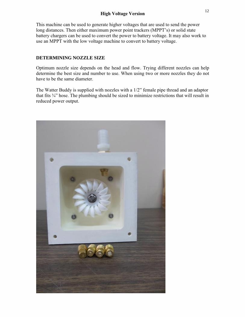
DETERMINING NOZZLE SIZE
Optimum nozzle size depends on the head and flow. Trying different nozzles can help
determine the best size and number to use. When using two or more nozzles they do not
have to be the same diameter.
The Watter Buddy is supplied with nozzles with a 1/2” female pipe thread and an adaptor
that fits ¾” hose. The plumbing should be sized to minimize restrictions that will result in
reduced power output.
13
BEARING REPLACEMENT
The Watter Buddy has two #6203 ball bearings that can be replaced. If any bearing noise
or wobble is noticed they should be replaced. A power loss could also indicate a bearing
change is needed. The bearings are pressed onto the shaft. A puller is needed to take the
bearings off and a press is needed to put the new bearings onto the shaft.
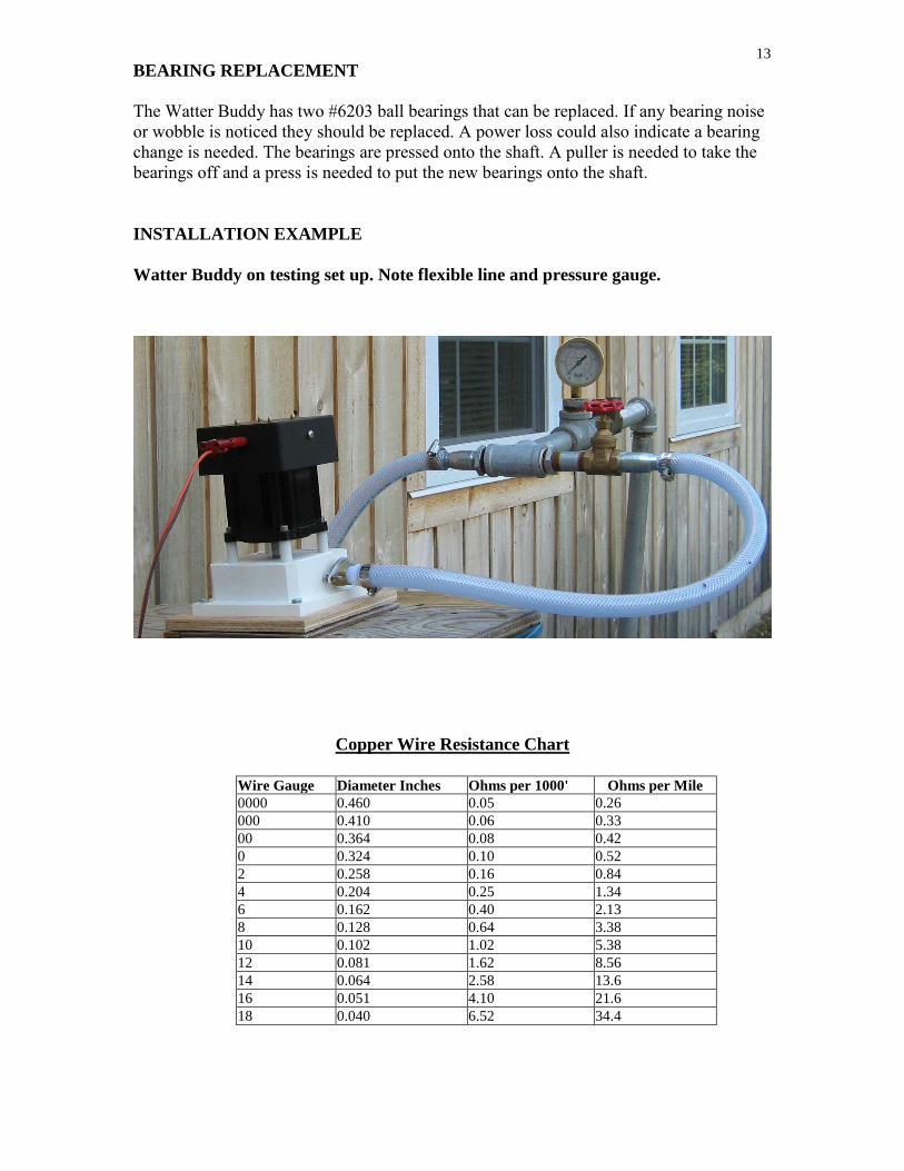
INSTALLATION EXAMPLE
Watter Buddy on testing set up. Note flexible line and pressure gauge.
Copper Wire Resistance Chart
Wire Gauge Diameter Inches Ohms per 1000' Ohms per Mile
0000 0.460 0.05 0.26
000 0.410 0.06 0.33
00 0.364 0.08 0.42
0 0.324 0.10 0.52
2 0.258 0.16 0.84
4 0.204 0.25 1.34
6 0.162 0.40 2.13
8 0.128 0.64 3.38
10 0.102 1.02 5.38
12 0.081 1.62 8.56
14 0.064 2.58 13.6
16 0.051 4.10 21.6
18 0.040 6.52 34.4
14
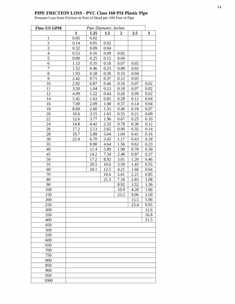
PIPE FRICTION LOSS - PVC Class 160 PSI Plastic Pipe Pressure Loss from Friction in Feet of Head per 100 Feet of Pipe
Flow US GPM Pipe Diameter, Inches
1 1.25 1.5 2 2.5 3
1 0.05 0.02
2 0.14 0.05 0.02
3 0.32 0.09 0.04
4 0.53 0.16 0.09 0.02
5 0.80 0.25 0.12 0.04
6 1.13 0.35 0.18 0.07 0.02
7 1.52 0.46 0.23 0.08 0.02
8 1.93 0.58 0.30 0.10 0.04
9 2.42 0.71 0.37 0.12 0.05
10 2.92 0.87 0.46 0.16 0.07 0.02
11 3.50 1.04 0.53 0.18 0.07 0.02
12 4.09 1.22 0.64 0.20 0.09 0.02
14 5.45 1.63 0.85 0.28 0.12 0.04
16 7.00 2.09 1.08 0.37 0.14 0.04
18 8.69 2.60 1.33 0.46 0.18 0.07
20 10.6 3.15 1.63 0.55 0.21 0.09
22 12.6 3.77 1.96 0.67 0.25 0.10
24 14.8 4.42 2.32 0.78 0.30 0.12
26 17.2 5.13 2.65 0.90 0.35 0.14
28 19.7 5.89 3.04 1.04 0.41 0.16
30 22.4 6.70 3.45 1.17 0.43 0.18
35 8.90 4.64 1.56 0.62 0.23
40 11.4 5.89 1.98 0.78 0.30
45 14.2 7.34 2.48 0.97 0.37
50 17.2 8.92 3.01 1.20 0.46
55 20.5 10.6 3.59 1.43 0.55
60 24.1 12.5 4.21 1.66 0.64
70 16.6 5.61 2.21 0.85
80 21.3 7.18 2.83 1.08
90 8.92 3.52 1.36
100 10.9 4.28 1.66
150 23.2 9.06 3.50
200 15.5 5.96
250 23.4 9.05
300 12.6
350 16.8
400 21.5
450
500
550
600
650
700
750
800
850
900
950
1000

15
PIPE FRICTION LOSS Polyethylene SDR - Pressure Rated Pipe
Pressure Loss from Friction in Feet of Head per 100 Feet of Pipe
Flow US GPM Pipe Diameter, Inches
0.5 0.75 1 1.25 1.5 2 2.5 3
1 1.13 0.28 0.09 0.02
2 4.05 1.04 0.32 0.09 0.04
3 8.60 2.19 0.67 0.19 0.09 0.02
4 14.6 3.73 1.15 0.30 0.14 0.05
5 22.1 5.61 1.75 0.46 0.21 0.07
6 31.0 7.89 2.44 0.65 0.30 0.09 0.05
7 41.2 10.5 3.24 0.85 0.42 0.12 0.06
8 53.1 13.4 4.14 1.08 0.51 0.16 0.07
9 16.7 5.15 1.36 0.65 0.18 0.08
10 20.3 6.28 1.66 0.78 0.23 0.09 0.02
12 28.5 8.79 2.32 1.11 0.32 0.14 0.05
14 37.9 11.7 3.10 1.45 0.44 0.18 0.07
16 15.0 3.93 1.87 0.55 0.23 0.08
18 18.6 4.90 2.32 0.69 0.30 0.09
20 22.6 5.96 2.81 0.83 0.35 0.12
22 27.0 7.11 3.36 1.00 0.42 0.14
24 31.7 8.35 3.96 1.17 0.49 0.16
26 36.8 9.68 4.58 1.36 0.58 0.21
28 11.1 5.25 1.56 0.67 0.23
30 12.6 5.96 1.77 0.74 0.25
35 16.8 7.94 2.35 1.00 0.35
40 21.5 10.2 3.02 1.27 0.44
45 26.8 12.7 3.75 1.59 0.55
50 32.5 15.4 4.55 1.91 0.67
55 18.3 5.43 1.96 0.81
60 21.5 6.40 2.70 0.94
65 23.8 7.41 3.13 1.08
70 28.7 8.49 3.59 1.24
75 32.6 9.67 4.07 1.40
80 10.9 4.58 1.59
85 12.2 5.13 1.77
90 13.5 5.71 1.98
95 15.0 6.31 2.19
100 16.5 6.92 2.42
150 34.5 14.7 5.11
200 25.0 8.70

GUARANTEE
This machine is guaranteed to change your life.
The fine print:
This ES & D water powered generator is warranted against defects in workmanship and materials. The
period that this covers is 90 days, starting at the date of shipment to the customer.
In the event that an ES & D machine is found to have defects in material or workmanship, the remedies of
repair or replacement of parts shall in each case be at the reasonable discretion of ES & D. Machines that
the purchaser claims are defective must be returned at the purchaser’s cost.
ES & D will not be responsible for problems caused by improper maintenance, faulty installation,
unauthorized modifications or additions, abuse, or any other cause not due to defects in the machine.
ES & D will not be held liable for consequential damages or interruption of service to the buyer. The buyer,
furthermore, by acceptance of the equipment assumes all responsibility for the consequences of its use.
After one year from the shipping date, all liability terminates and no action for any breach of any such
warranty may be commenced.

Personal Hydropower
Product Information Model # _____________________ Serial # ____________________
Date Purchased __________________________________________
Purchased From __________________________________________
Name: __________________________________________________
Address: ________________________________________________
City: ___________________________________________________
State/Prov: _________________ Zip/Postal Code: ______________
Telephone: ______________________________________________
Email: __________________________________________________
Comments: ______________________________________________
________________________________________________________
__________________________________________
Made in Canada
By
Energy Systems and Design Ltd.
PO Box 4557
Sussex NB
Canada E4E 5L7
Phone +1 (506) 433-3151
Fax +1 (506) 433-6151
Email: [email protected]
Website: www.microhydropower.com