the value of integrated design of offshore wind turbine
TRANSCRIPT
The value of integrated design of offshore wind turbine foundationsKristoffer Skjolden SkauNorwegian Geotechnical Institute
Bergen 2019-09-12

NGI’s mission and marketsWe research and develop solutions for both industry and society, ensuring that we live, build and travel on safe ground
Services grouped into four markets─ Offshore energy─ Building, construction & transportation─ Natural hazards─ Environment

Offshore geotechnical engineering
Since 1970s Development of the required technology for the oil and gas adventure in Norway
From 2010 Offshore wind activitiesDesign, installation and monitoring of offshore wind foundations

NGI involvement in offshore wind

Work with all foundation types

Work with all foundation types

Work with all foundation types

NGI Oslo and Houston advanced Laboratories

Design and advanced analyses

Field testing and monitoring

Integrated designis a comprehensive holistic approach todesign which brings together specialisms usually considered separatelyDriven by :─ The real coupling of the processes and physical mechanisms governing the
design ─ The digitalization of data and workflows that replace old data storage and
manual workflows

Integrated design analysesREDWIN 1 developed the capabilities in modelling the physical interactions of the turbine. Integration of the physical mechanisms in the system
Site investigation and laboratory
testing
Soil parameters
Compute foundation response
Implement in integrated analyses
Integrated analyses to
determine OWT design
Design work flow
REDWIN

Integrated design analyses

Integrated design analysesREDWIN research project

Foundation type Applicable model Primary loading conditions
REDWIN model 1
Horizontal loading (but distributed 1D model can be applied to any DOF)
REDWIN model 2
Coupled Horizontal and
Moment loading
REDWIN model 3
Coupled Vertical, Horizontal and
Moment loading
REDWIN model 3
Coupled Vertical, Horizontal and
Moment loading

Integrated design analysesDesign is more than analysesREDWIN 2 takes an integrated approach to the complete foundation design processDigital and automated work flow replace manual work flow

Manual work flow Digital and automated work flow replace manual work flow
Pictures and figures are meant for illustration only
Geophysical survey

Manual work flow

Manual work flow

Manual work flow D
L
t
Pictures and figures are meant for illustration only

Manual work flow Manual work flow require simplificationsA few design casesOptimal design for the defined cases
D
L
t
D = 6L = 26
D = 5.5L = 24
Cluster 1 Cluster 2
Pictures and figures are meant for illustration only
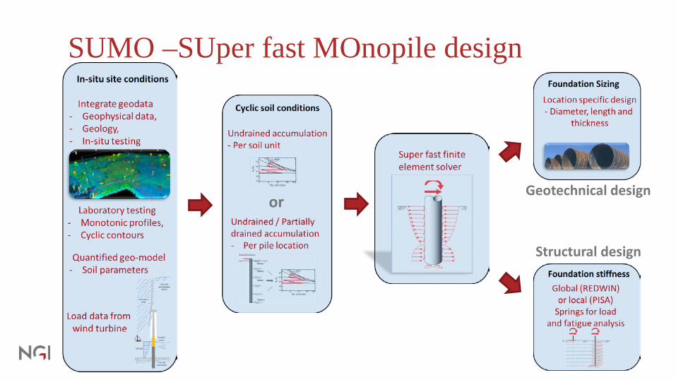
SUMO –SUper fast MOnopile design
orGeotechnical design
Structural design

Integrated designDigital and automated work flow replace manual work flowNot data reports, only data

From a point1D 2D 3DGeotechnical data is typically collected as a limited number of sparse 1D points in the ground model
CPTs and/or Engineering judgement can be used to scale soil parameters in 1D borehole
Inversion/Co-Kriging/ Machine learning can be used to scale to 2D
Interpolation or Geostatistics can be used to scale to 3D
(e.g. Linear, Spline, Kriging)

SUMO –SUper fast MOnopile design
orGeotechnical design
Structural design

SUMO - INFIDEP
Axisymmetric finite element with asymmetric loadingThe displacements are expanded from 2D to 3D with a Fourier series expansion

SUMO - INFIDEPAnalyses of PISA tests

SUMO – Sizing with INFIDEP
Pictures and figures are meant for illustration only

Integrated designOptimal design across the site
D
L
t
D = 6L = 26
D = 5.5L = 24
……D = 4.9L = 18
D = 5.3L = 24
D = 5.5L = 23
D = 6.5L = 26
D = 5.8L = 24
D = 5.7L = 23
D = 5.6L = 22
A01 A02 A03 A04 B01 B02 B03 B04 C01
Pictures and figures are meant for illustration only

Monopile design – spatial variability?
Pictures and figures are meant for illustration only

Integrated design
orGeotechnical design
Structural design

Integrated design – final remarks Integrated design is more than a buzzwordIt require new digital workflowsIt require cross-discipline thinking and collaborationOffshore wind is likely a front runner due to the number of structures and the focus on optimizationThe value is the ability to optimize; and the ability comes with reliable technical models and effective processes.

Thank you for your attention !