the use of microfluidics in rheology
TRANSCRIPT

Review
308
The Use of Microfluidics in Rheology
Xin Hu, Pouyan E. Boukany, Orin L. Hemminger, L. James Lee*
The combination of microfluidics and fluorescent-labeled DNAmolecules in rheology providesa unique opportunity to relate the microstructure of polymer molecules to their macroscopicproperties. For example, the direct visualization of amodel polymer system such as single DNAdynamics of individual DNA molecules, improves ourunderstanding of the rheological behavior of diluteand concentrated polymer solutions. This review sum-marizes the microfluidic rheology for synthetic polymerand DNA solutions, including both experimental andsimulation efforts, in investigating dilute and concen-trated polymer solutions.
Introduction
Rheology is the science of the deformation and flow of
materials. Colloids, emulsions, liquid crystals, synthetic
polymersandbiopolymers (DNA,proteins), foams, gels, and
membranes are widely used in our everyday life. The
rheological properties of these complex fluid systems are
oftencomplicatedbecauseof their structural viscoelasticity
as well as interactions among their fluid constituents.[1–5]
A central focus in the field of polymer rheology has been
constitutive relations derived from information gathered
from conventional rheometric measurements. With the
newly developed tools such as microfluidics-based rhe-
ometers and advanced fluorescence microscopy, we are
now able to directly image and understand the micro-
structures and dynamic behavior of long-chain molecules
in well-defined fluid fields and relate the visualization to
macroscopic rheological responses. The lengthscale studied
in conventional rheology is usually on the order of one
millimeter. Thus, conventional rheology or macrorheology
X. Hu, P. E. Boukany, O. L. Hemminger, L. J. LeeNanoscale Science and Engineering Center for AffordableNanoengineering of Polymeric Biomedical Devices (CANPBD)E-mail: [email protected]. E. Boukany, L. J. LeeDepartment of Chemical and Biomolecular Engineering, The OhioState University, Columbus, OH, 43210 USA
Macromol. Mater. Eng. 2011, 296, 308–320
� 2011 WILEY-VCH Verlag GmbH & Co. KGaA, Weinheim wileyonline
cannot provide significant direct information on the
molecular nature of fluids. For this reason microrheology,
i.e., rheology at the microscale, is receiving increased
attention in recent years.[6]
There are a number of advantages to usingmicrofluidics
in rheology. First, microfluidic devices can produce high
shear rates, high Weissenberg (Wi) and Deborah (De)
numbers at low Reynolds (Re) numbers, not achievable
by conventional rheometric measurements; where
Wi ¼ _gl, with _g being the local characteristic shear rate,
and l the dominant relaxation time, De¼ l/t, with t being
the characteristic flow time and Re¼ r _gw2hh _gð ÞðwþhÞ, with r being
fluid density, w the width and h is the height, and h _gð Þ theshear viscosity. Second, only a small amount of sample is
needed in microfluidics, thus making high-cost materials
and reagents such as DNA solutions affordable as a model
fluidspolymer inrheologicalmeasurements. Third, theflow
field in themicrofluidic device systems can also be directly
observed imaged by an inverted or confocal florescence
microscope and analyzed by the microparticle image
velocimetry (mPIV) technique[7] with the fluid viscosity
being estimated simultaneously by either mounting a
pressure transducer onto the micro-fabricated device or
applying non-contact force measurement techniques such
asusinganoptical tweezers.[8] Furthermore, different types
of flows can be easily generated in microfluidic-based
devices without any moving parts. For example, micro-
fluidic devices consisting of several microchannels have
been designed to produce extensional, mixed shear, and
library.com DOI: 10.1002/mame.201000246

L. James Lee is the Helen C. Kurtz Professor ofChemical Engineering at The Ohio State Univer-sity, and the Director of NSF Nanoscale Scienceand Engineering Center for Affordable Nano-engineering of Polymer Biomedical Devices. Hereceived a BS degree from National Taiwan Uni-versity and a Ph.D. degree from University ofMinnesota in 1979. His research covers polymerengineering, micro-/nanotechnology, and bio-technology. He has> 220 papers and 25 patents.Dr. Lee is a Fellow of Society of Plastics Engineers(SPE). He received the 2008 Malcolm E. PruittAward from Council of Chemical Research, 2008Engineering/Technology Award and 2010 Inter-national Award from SPE.
Xin Hu received the M.S. degree from PekingUniversity, China in 2000 and the Ph.D. degree inMechanical Engineering from The Ohio StateUniversity in 2006. He worked as a researchengineer in the center for Affordable Nanoengi-neering of Polymeric Biomedical Devices from2006 to 2010. His researchmainly focused on themesoscopic simulation of polymeric flows, FEMsimulation of electrokinetic micro/nanofluidics,Brownian dynamics simulation of long chainpolymers in microfluidics, and FEM simulationof cell electroporation in micro/nanodevices.Now he is a thermal and CFD scientist in UES,Inc. and works on simulation of thermal storagemanagement.
Pouyan E. Boukany obtained his M.S. degree inTextile Engineering with major in Textile Chem-istry and Fiber Science from the Isfahan Univer-sity of Technology, Iran. He received his Ph.D. inPolymer Science from University of Akron in2008. His doctoral work was to explore thenonlinear flow behavior of entangled DNA fluidsin Professor Shi-Qing Wang’s group. He is cur-rently a Postdoctoral Research Associateworkingwith Professor L. James Lee in the Center forAffordable Nanoengineering of Polymeric Bio-medical Devices at The Ohio State University.
The Use of Microfluidics in . . .
www.mme-journal.de
rotational flow patterns as in a ‘‘four-roll mill’’ type
rheometer,by adjusting the relative flow rates in micro-
channels.[10,11] Since thesemicrofluidic devices do not have
any moving parts, the fabrication is much easier and thus
less costly. Finally,microfluidic rheologyconductedon ‘‘lab-
on-a-chip’’ devices can be used to study non-Newtonian
flow behavior responses of biological fluids for medical
applications. Examples include serumflow inbloodvessels,
protein and DNA flow manipulation in bioseparation
devices, and controlled drug/gene delivery.
Polymer materials studied in rheology range from
solutions to melts. Due to space limitations, we only cover
the microfluidic rheology of polymer solutions here. This
review article is organized in the following order: Section 1
is a brief introduction to microfluidic rheology and its
advantages. Section 2 focuses on the experiments and
simulations of microfluidic rheology of conventional poly-
mer solutions. Section 3 discusses the use of DNAmolecules
as a model polymer for molecular imaging in microfluidic
rheology. In Section 4, we give several future directions
relevant to microfluidic rheology are proposed. Finally, a
summary and conclusions are provided in Section 5.
Microfluidic Rheology of Polymer Solutions
In this section, we focus on the dynamic response of
polymer solutions through micro-fabricated flow geome-
tries. The flow fields of such polymer fluids inmicrofluidics
can be characterized by using either micro-tracer particles
or numerical simulation approaches.
Experimental Observations of Flow Instabilities inMicrofluidics
Most polymers used in our daily life, from plastics to
synthetic fibers to elastomers, aremade fromentangled long
chains in themolten or solution state. By pushingor drawing
them through an extrusion shaping die or an injection
molding machine, these materials can be formed into
desirable shapes to develop useful products.[12,13] At high
deformation rates (De or Wi> 1.0), these entangled fluids
exhibit complex flow phenomena such as shear thinning,[14]
transient stress overshoot in start-up shear,[15,16] wall slip/
shear banding during shear,[17] necking during extension,[18]
rod-climbing, vortex formation in extrusion, spurt in
capillary flow, and extrudate (or die) swell and/or melt
fracture.[12,13] Molecularmechanisms of these flowphenom-
ena are still unclear despite decades of intensive experi-
mental and theoretical investigation.[19] New insights in
polymer rheology can be gained through the integration of
microfluidics-based ‘‘rheometer-on-a-chip’’ and optical/con-
focal microscopy, i.e. rheo-microscopy.
Flow through a contraction channel is one of the most
widely studied geometries in the field of polymer rheology
www.MaterialsViews.com
Macromol. Mater. Eng. 2
� 2011 WILEY-VCH Verlag Gmb
because of its importance in many polymer processing
operations. For example, the gross melt fracture of the
extrudate may be originated from the instability near the
entrance to a contraction geometry. Using a microfluidic
device, our group showed that the entry flow pattern in a
converging flow geometry was very different for two
aqueous polymer solutions (2% polyethylene oxide, PEO
and 1% hydroxyethyl cellulose, HEC) due to strain-hard-
eningvs. softening response in theextensionalflow(shown
in Figure 1 A–C). Local strain-hardening of PEO led to the
enhanced vortex formation near the inlet of a micro-sized
converging channel (with 368 convergence angle).[20]
011, 296, 308–320
H & Co. KGaA, Weinheim309

Figure 1. (A) Extensional response of PEO and HEC solutions. Entrance flow patterns for(B) PEO and (C) HEC solution. Reproduced with permission.[20] Copyright 2006, Springer.
Figure 2. (A) Summarizing 4:1 macroscopic contraction flow experiments on a Wi-Re sfluids. Summary of flow patterns in theWi-Re space for (B) different semi-dilute PEO solutEI¼Wi/Re¼ 2.8–68 at the same concentration of PEO solution (�0.075% PEO) inpermission.[21] Copyright 2005, Elsevier.
310 Macromol. Mater. Eng. 2011, 296, 308–320
� 2011 WILEY-VCH Verlag GmbH & Co. KGaA, Weinh
www.mme-journal.de
X. Hu, P. E. Boukany, O. L. Hemminger, L. J. Lee
Figure 2A shows regions of the Wi-Re
space for contraction flows containing
both inertia and elasticity in macroscale
experiments.[21] The highest achievable
Wi was less than 10 for Re less than one
in such cases. Using dilute aqueous
polymer solutions in contraction-
expansion microchannels, a similar flow
behavior over amuch broader range of Re
(0.44< Re< 64) andWi (0<Wi< 548) has
been achieved, which had previously
been unexplored because such conditions
were not accessible in the equivalent
macroscale experiments. We briefly
introduce several representative studies
here.
Rodd et al.[21] studied the flowbehavior
of semi-dilute PEO. solutions to in a
16:1:16 contraction-expansion flow geo-
metry. Both pressure drop and flow
visualization were used to characterize
pace for shear thinning viscoelastic and Bogerions (0.05–0.3% PEO), and (C) different ranges ofa contraction microchannel. Reproduced with
eim www.MaterialsViews.com

Figure 3. Summary of flow patterns in theWi-Re space for four different DNA solutionsfrom weakly to highly entangled solutions in a 4:1 contraction microchannel.Reproduced with permission.[24] Copyright 2010, Elsevier.
The Use of Microfluidics in . . .
www.mme-journal.de
the flow dynamics over a range of Re
(0.44<Re< 64) and Wi (0<Wi< 548) as
shown in Figure 2B. They reported that
the onset of elastic instabilities at the
contraction entry occurred at a criticalWicof 50.[21,22]
Rodd et al. also prepared solutionswitha
constant concentration of PEO but four
different glycerol-water mixtures to vary
the viscosity of the solvent. This allowed
them to investigate the entry flow
behavior in the Wi-Re space for four
different elastic numbers (El¼Wi/
Re¼ 2.8, 7, 19, and 68). Each solution
exhibited the same four flow regimes,
identified as Newtonian like flow, steady
viscoelastic flow, diverging flow, and
elastic corner vortex growth as shown in
Figure 2C. For the three lower El values, 2.8,
7, and 19, the Wi at which the transition
between two flow regimes occurred was
found to be aweak function of El, while the
same transition occurred at a higher Wi
Figure 4. Dye advection patterns for a cross-channel flow withtwo inputs and two outputs for (a) a Newtonian fluid, and (b) aPAA flexible polymer solution (De¼ l/t¼ 4.5), where the interfacebetween dyed and un-dyed fluid is deformed by flow instability.(c) and (d) Particle streak lines corresponding to (a) and (b)showing the symmetry-breaking instability. Reproduced withpermission. [27] Copyright 2006, American Physical Society.
when the El value was 68.[22]
Gulati et al. employed a semi-dilute DNA solution
containing 400mg/mL (0.04wt.-%) of l-DNA and investi-
gated its flow behavior through a 2:1 planar contraction
microchannel.[23] When 3.9<Wi< 193.3, a symmetric
growth of the corner vortex was observed. Recently, our
group used four different entangled DNA solutions with
concentrations ranging from 0.1 to 1.0wt.-% (with a wide
range of entanglements per chain Z¼ 7–55) to study the
flow of entangled fluids through a 4:1 contraction
microchannel. We achieved Wi higher than 20,000 with
Re less than 0.5, a regime not been reached in the past. For
weakly entangled solutions (Z< 30), the vortex flow was
dominant at high flow rates. However, for well entangled
DNA solutions (Z� 30), an unusual time-dependent shear
banding was observed near the contraction entrance
(shown in Figure 3).[24]
Microfluidics with complicated geometries such as
cross-slot, stagnation point, triangular (nozzle/diffuse)
shape, flow resistors and T-shaped geometries have
also been used to study flow instabilities of non-
Newtonian fluids.[25] Pathak and Hudson used a cross-
slot microfluidic device to investigate the extensional
rheology of a polymer solution. At high flow rates, a
central birefringent band representing a highly aligned
microstructure was observed near the stagnation point.[26]
Using the same geometry, Arratia et al. showed that
the velocity field of a polyacrylamide solution (PPA)
became strongly asymmetric with non-periodic fluctua-
tion at sufficiently high strain rates and low Re (shown
in Figure 4).[27]
www.MaterialsViews.com
Macromol. Mater. Eng. 2
� 2011 WILEY-VCH Verlag Gmb
Recently, Soulages et al. used a T-shapedmicrochannel to
investigate the instability of the steady planar stagnation
flow of PEO solutions. As shown in Figure 5, a strand of
highly oriented polymeric material was formed in the
011, 296, 308–320
H & Co. KGaA, Weinheim311

Figure 5. Viscoelastic (a–e) and Newtonian (f–j) flow patterns as a function of flow ratein a T-shaped microchannel. Reproduced with permission.[28] Copyright 2009, Elsevier.
312
www.mme-journal.de
X. Hu, P. E. Boukany, O. L. Hemminger, L. J. Lee
region of the strong planar extensional flow, resulting in an
additional symmetry-breaking transition at intermediate
Wi. A flow transition from a steady to an unsteady three-
dimensional flow was observed at a critical Wi for each
stagnation flow.[28]
Sousa et al. employed a microfluidic rectifier to produce
creeping flow conditions.[29] For viscoelastic fluids, the
pressuredropwas foundtobeconstant in theflowdirection
at low flow rates. However, increasing the flow rate led to
an anisotropic flow resistance in the forward and
backward flow directions at the same pressure drop, i.e.,
rectification effects emerged. The viscoelastic fluid flow
became unsteady in the forward direction due to the
emergence of elastic instabilities and the flow resistance
increased sharply as a function of the flow rate (shown in
Figure 6).
Figure 6. Flow patterns of a PAA fluid in the microchannel with a triangular shapeReproduced with permission.[29] Copyright 2010, Elsevier.
Macromol. Mater. Eng. 2011, 296, 308–320
� 2011 WILEY-VCH Verlag GmbH & Co. KGaA, Weinh
Simulation of Viscoelastic Fluids inMicrofluidic Rheology
Most polymer fluids exhibit shear-rate
dependent viscosity and some solid-like
elastic properties. These two properties
are tightly inter-connected as viscoelas-
ticity, a critical property of many non-
Newtonian fluids. The governing
equations of non-Newtonian fluid flows
contain an unknown polymer stress
tensor, making the flow simulation a
non-trivial task. Typically, close-formed
constitutive equations (CEs) are used to
solve for polymer stresses. This macro-
scopic simulation approach only solves
the macroscopic variables such as poly-
mer stresses and the velocity field. Con-
ventional simulation methods such as
finite element (FE), finite difference (FD),
and finite volume (FV) methods are
applied to simulate viscoelastic fluids using various CEs
(for more information, please refer to.[2,3])
Several researchers have applied the macroscopic
simulation approach to microfluidic rheology. Poole et al.
investigated the stability of an upper-convected Maxwell
(UCM) fluid in a cross-slot microchannel,[30] while Soulages
et al. studied the instability of a Phan-Thien-Tanner (PTT)
fluid in a T-shaped microchannel.[28] Although some CEs
have considered the polymer configuration by treating
polymer molecules as bead-spring chains,[4,31–34] the CEs-
based simulation of polymer flows cannot represent the
true behaviors of polymers. For example, the polymer
chains near the wall behave differently from those in the
bulk flow due to the effects of hydrodynamic interaction
(HI) and repulsive forces from the wall. Since CEs do not
consider the existence of the channel wall, the effect of
polymer-wall interactions on polymer
flow cannot be exhibited in the macro-
scopic approach. The CEs-based simula-
tion also cannot achieve high Wi or De
numbers due to severe numerical
instability.
An alternative way to simulate viscoe-
lastic fluids is the so-called mesoscopic
approach. This approach simulates poly-
mer molecules in a coarse-grained way
and calculates polymer stresses by an
ensemble average. For example, the
CONNFFESSIT (Calculation of Non-New-
tonian Flow: Finite Elements andStochas-
tic Simulation Technique) method is a
mesoscopic simulation method devel-
oped by Laso and Ottinger.[35] In this
eim www.MaterialsViews.com

The Use of Microfluidics in . . .
www.mme-journal.de
method, the flow domain is first discretized into a finite
element mesh. Polymer molecules are simplified as bead-
spring or bead-rod dumbbells or chains. There are two
differentmethods to calculate the configuration of polymer
chains. One is the Lagrangian method by throwing dumb-
bells or chains into the flow field and tracking their
positions and conformation; the other is the Eulerian
method by associating dumbbells or chains with the nodal
point and only calculating their configuration changes. The
latter method is called the Brownian configuration field
(BCF) method,[36] as shown in Figure 7.
The CONNFFESSIT method uses the iteration method to
calculate the steady state velocity field. At the beginning, a
Newtonian velocity field is used to calculate the config-
uration of polymer chains in the flow field. Then polymer
stresses are calculated with the Kramer’s expression.
Finally the velocity field is updated by adding the
contribution of polymer stresses. This process is repeated
until the numerical solution is converged.[37]
The CONNFFESSITmethod has been successfully applied
to simulate diverse viscoelastic fluid flows (steady or
transient) such as in 4:1 abrupt contraction,[38,39] journal
bearing flow,[40] passing single cylinder or cylindrical
arrays,[39,41] die exit,[42] gas assisted injection molding,[43]
and others. The application of CONNFFESIT inmicro-scaled
viscoelastic flows is straightforward. For example, our
group studied the vortex formation in a channel with
microfeatures.[44] We used the FENE dumbbell in CON-
NFFESSIT and obtained similar results to those shown by
experiments.
Although the CONNFFESSIT-based simulation can reach
a higher Wi number than CEs-based simulation, it still
cannot achieve the same Wi numbers observed in the
microfluidics experiments, which could be as large as
20,000 with concentrated polymer solutions. One way to
solve this problem is to replace the bead-spring dumbbell
with the bead-spring chain in the simulation.[45,46] In the
future, a finer-grained simulation approach such as
molecular dynamics (MD) and the multi-scaled simulation
methods combining MD, BDS and FEM are expected to
emerge as a solution for modeling viscoelastic flows,
particularly for microfluidic rheology.
Figure 7. A schematic of CONNFFESSIT with the BCF method.
www.MaterialsViews.com
Macromol. Mater. Eng. 2
� 2011 WILEY-VCH Verlag Gmb
DNA as a Model Polymer for MolecularImaging
Macroscopic properties of polymer solutions are directly
related to the dynamics of individual polymer molecules
and their interactions. Once the behaviors of individual
polymer molecules and molecule-molecule interactions
canbeanalyzed, the reasonwhyapolymersolutionshowsa
particularproperty inacertainflowfieldcanbeunderstood.
However, conventional polymermolecules are too small to
be directly observed. Also macroscopic experimental
techniques such as light scattering and birefringence
cannot detect changes in microscopic configurations of
polymer molecules during flow.
This was the situation until in 1994 when Steven Chu’s
group first used pre-stained long chain DNA as a model
polymer to investigate the rheological properties of dilute
polymer solutions at the molecular level.[47] DNA
molecules are much larger than typical polymer molecules
(> 10M vs.< 1� 106 gmol�1 in molecular weight). For
example, the contour length of a naked l-DNAmolecule (48
kbps, molecular weight � 31.5� 106 gmol�1) is around
16mm.Alsowhen labeledwithfluorescent dye, DNA canbe
directly observed with the fluorescence microscope. The
brilliant idea of using DNA as a model polymer directly
connects microscopic dynamics to macroscopic properties
of polymer solutions and opens a new door to the field of
polymer rheology.
Experiments and Simulations of DNA Dynamics inDilute Solutions
Free Relaxation of DNA Molecules
Perkins, et al. first studied the free relaxation of individual
fluorescent-dyed and highly-extended DNA molecules in
dilute solutions.[48] The relationship between the visual
length of DNAmolecules and timewas recorded in order to
study the free relaxation process. Figure 8 shows the visual
length vs. time for three types of DNA molecules with
contour lengths of 7.7, 21.1, and 39.1mm. Inset shows the
relaxationprocessof a tetheredDNAmoleculewithoneend
011, 296, 308–320
H & Co. KGaA, Wein
attached to a polystyrene latex micro-
sphere, which was trapped by the optical
tweezers.
From this data, the longest relaxation
time can be calculated. Also DNA mole-
cules with different lengths were used to
investigate the scaling law on the longest
relaxation time t. They found that t follows
a scaling law on the polymer length L,
t� L3y, where 3n is the scaling exponent.
Here 3y ¼ 1:66� 0:10 or 1:65� 0:13
depending on the data analysis methods
heim313

Figure 8. Relaxation of initial fully stretched tethered DNA mol-ecules with three different contour lengths. Inset is the relaxationprocess of a DNA molecule. Reproduced with permission.[47]
Copyright 1994, American Association for the Advancement ofScience.
314
www.mme-journal.de
X. Hu, P. E. Boukany, O. L. Hemminger, L. J. Lee
used in their experiments. This agrees well with the
experiments by intrinsic viscosity measurements[48] and
dynamic light scattering,[49] but disagrees with the
analytical theories in that the Rouse theory gives 3n¼ 2
for the freely draining chain; Zimm model predicts
that 3n¼ 1.5 for the ‘‘theta’’ solvent by considering the
hydrodynamic interactions; and 3n¼ 1.8 for a ‘‘good’’
solvent.[31,50] Thus, none of the current theoretical models
can reliablypredict the scaling law in the relaxationprocess
of DNAmolecules. Effects of monomer-solvent interaction,
hydrodynamic interaction, excluded volume force and the
even nonlinear elastic force of DNA chain should be added
into consideration in the theory.
Figure 9. (A) Coil-stretch transition for DNA molecules with four differextensional flow (inset); (B) ensemble average extension for difpermission.[51] Copyright 1997, American Association for the Advance
Macromol. Mater. Eng. 2
� 2011 WILEY-VCH Verlag Gmb
Coil-Stretching Transition of DNA Molecules in a PureExtensional Flow
Compared to the relaxation process, the transition of DNA
configuration from the equilibrium state to the non-
equilibrium state is a rather interesting topic of study.
One of thewidely usedmethods to drive DNAmolecules to
the non-equilibrium state is by using different types of
hydrodynamic flows. Since the velocity gradient can be
decomposed into symmetric and anti-symmetric parts,
there are typically two types of flow patterns: the
extensional flow related to the symmetric part of the
velocity gradient and the pure rotational flow related to the
anti-symmetric part of the velocity gradient. Other flow
patterns such as the simple shear andmixed flows are their
combinations.
Chu’s group investigated dynamics of untethered l-DNA
molecules inanearly2Dpureextensionalflowgenerated in
a cross-channel.[51,52] They observed the stretching of DNA
moleculeswhen theDenumberwas larger than0.4, slightly
less than the theoretical value of 0.5. With the aid of
fluorescent microscopy, Perkins et al. studied the coil-
stretch transition of DNA molecules with seven typical
initial conformations: dumbbell, half dumbbell, kinked,
folded, uniform, extended, and coil [53]. They found that the
conformation change of aDNAmoleculewas dependent on
its initial conformation. DNA molecules with different
initial conformations showed different coil-stretch transi-
tion process. Figure 9(A) shows the coil-stretch transitions
of DNA molecules with four initial conformations: dumb-
bell, half dumbbell, kinked and folded, while the averaged
extension vs. residency time for different initial conforma-
tions is shown in Figure 9(B). Such strongheterogeneity due
to the ‘‘individualism’’ of polymer molecules in the
extensional flow cannot be obtained by macroscopic
measurements such as light scattering and birefringence.
ent types of initial conformation near the stagnation point of a pureferent initial conformation vs. residency time. Reproduced withment of Science.
011, 296, 308–320
H & Co. KGaA, Weinheim www.MaterialsViews.com

Figure 10. Extension vs. residence time, or strain for DNA molecules with different initialconformations under (a) De¼ 2; (b) De¼ 48. Reproduced with permission.[52] Copyright1998, American Association for the Advancement of Science.
The Use of Microfluidics in . . .
www.mme-journal.de
The stretching of single DNA molecules under different
extensional rates, or De numbers was also studied. It was
found that both the amount of stretched DNA molecules
and the ensemble averaged extension increased at a larger
De number. Figure 10 shows that most of coiled DNA
molecules maintained their coiled status at smaller De
numbers, while all were stretched at a larger De number.
This indicates that DNA molecules experienced larger
deformation with a larger extensional rate, or a larger
stretching force.
The coil-stretch transition ofDNA in the extensional flow
has been successfully recaptured by the Brownian
dynamics simulation (BDS). Larson et al. showed that the
coil-stretch transition of l–DNA molecules can be simu-
lated with BDS using the worm-like chain (WLC) model.[50]
They did not consider the effect of hydrodynamic interac-
tion (HI) in the simulation. However, by adjusting the
effectivepersistence length, theyobtainedalmost the same
results as experiments done by Chu’s group.
The HI effect on polymer dynamics in bulk has been
investigatedbymany researchers.[54,55] TheHIvelocity, as a
perturbation to the bulk flow, is calculated through a
mobility tensor such as the Oseen-Burger tensor. However,
this tensor isnon-positivedefinitewhentwobead locations
are close. Thus, the Rotne-Prager-Yamakawa (RPY) tensor is
chosen to replace the Oseen-Burger tensor in the calcula-
tion. Heish and Larson applied the RPY tensor as the
mobility tensor in the BDS of dynamics of Polystyrene (PS)
and l-DNAmolecules in the extensional flowwith HI.[56,57]
Their results showed that theHI effectwasmore important
for the dynamics of short PS molecules, and it could be
neglected for the dynamics of l-DNA since the HI velocity
decreased rapidly with the increased distance between
two beads.
www.MaterialsViews.com
Macromol. Mater. Eng. 2011, 296, 308–320
� 2011 WILEY-VCH Verlag GmbH & Co. KGaA, Weinheim
For l-DNA, the effect of HI could be
neglected in the simulation without
affecting the overall stretching
amount as long as the effective persis-
tence lengthwasadjusted tomatch the
relaxation data in experiments. How-
ever, for a longer DNA with contour
length � 1.3mm, which is 62 times
longer than l-DNA, the HI effect could
not be neglected any more. Hysteresis
phenomenonwas observed by Schroe-
der et al. with such long DNA in the
extensional flow.[58] They found that
there are two different stretching
states of DNA molecules for the same
Denumber, or strain rate.At thecertain
range of strain rate, both coiled and
stretched DNAmolecules co-existed in
the buffer solution. In fact, this is the
first order coil-stretch transition pro-
posedbydeGennesand this ‘‘bistable equilibrium’’ is due to
the strong ‘‘deformation-dependentdrag’’ inducedbyHI for
such longDNAmolecule.[59] The conformationhysteresis of
long DNA molecules was simulated using BDS.[60] In the
simulation, DNA molecules with two different initial
configurations (stretched and coiled) were considered.
Quantitative agreementwas achieved between the experi-
ment and BDS.
Tumbling of DNA Molecules in Simple Shear & MixedFlows
DNA dynamics in a simple shear flow was also studied by
Chu’s group.[61] They found thatDNAmolecules displayeda
tumbling movement shown by the schematic in
Figure 11(a). A DNAmolecule can be stretched to be nearly
aligned to the flow direction (here it is along the x-axis
direction). Then if the y-component of Brownian force
slightly rotates the DNA molecule, two ends of the DNA
molecule might be exerted by external forces in the
opposite direction andmove towards their center-of-mass.
Thus, DNAmoleculewill be retracted to a coiled shape. This
is the so-called ‘‘coil-stretch-tumbling-recoil’’ movement of
DNA molecules in the simple shear flow. In experiments,
Smithetal. observedthat therewere threetypicalbehaviors
ofDNAmolecules in theshearflowasshowninFigure11(b).
In the first row, the DNA molecule showed a ‘‘coil-stretch-
tumbling-recoil’’ movement. In the second row, the DNA
molecule was stretched gradually to a certain length and
maintained its shape. In the third row, the stretching of
DNA molecule was weak, but its conformation changed
greatly and the ‘‘tumbling’’ movement was observed.
BDS has been successfully applied to simulate DNA
dynamics in the simple shear flow.[62] Hur et al. investi-
gated theaveraged stretchamountvs. theWinumberusing
315
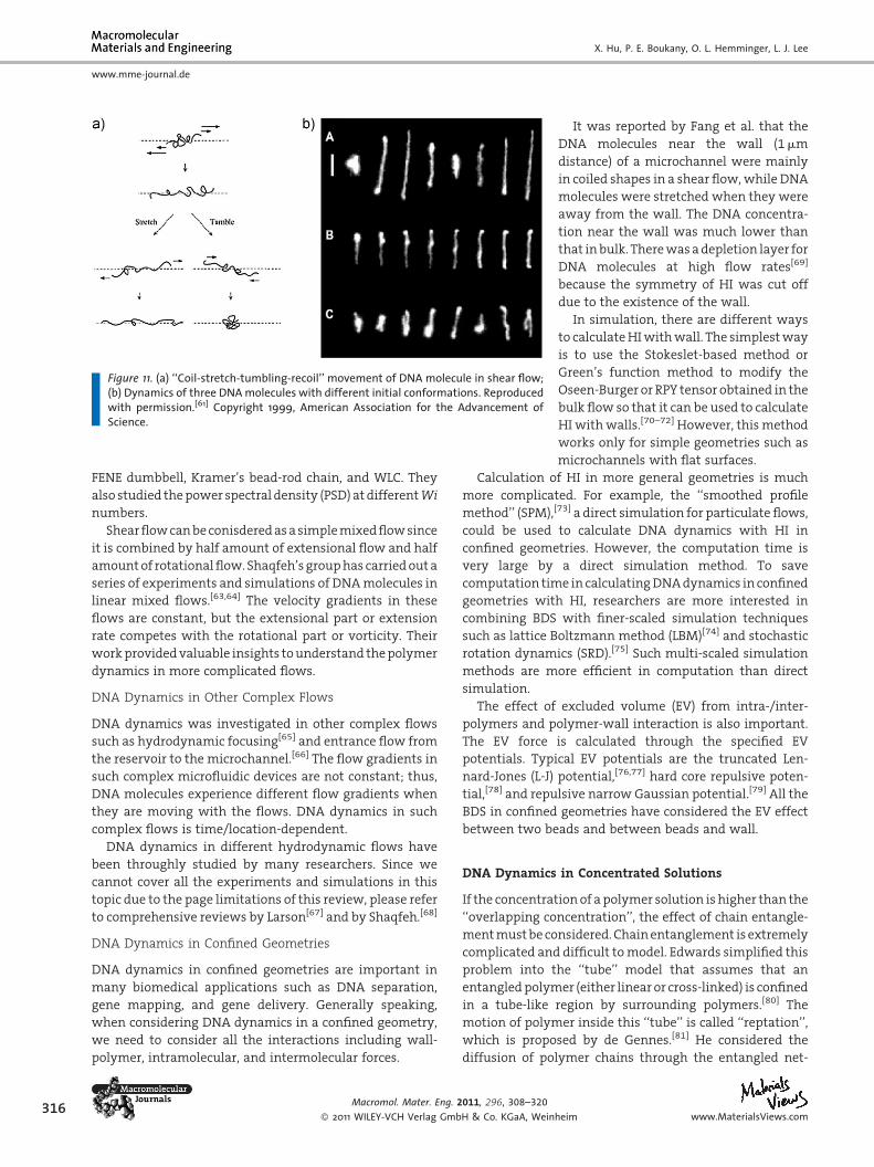
Figure 11. (a) ‘‘Coil-stretch-tumbling-recoil’’ movement of DNA molecule in shear flow;(b) Dynamics of three DNAmolecules with different initial conformations. Reproducedwith permission.[61] Copyright 1999, American Association for the Advancement ofScience.
316
www.mme-journal.de
X. Hu, P. E. Boukany, O. L. Hemminger, L. J. Lee
FENE dumbbell, Kramer’s bead-rod chain, and WLC. They
also studied thepower spectral density (PSD) atdifferentWi
numbers.
Shearflowcanbeconisderedasasimplemixedflowsince
it is combined by half amount of extensional flow and half
amountof rotationalflow. Shaqfeh’s grouphas carriedouta
series of experiments and simulations of DNAmolecules in
linear mixed flows.[63,64] The velocity gradients in these
flows are constant, but the extensional part or extension
rate competes with the rotational part or vorticity. Their
workprovidedvaluable insights tounderstand thepolymer
dynamics in more complicated flows.
DNA Dynamics in Other Complex Flows
DNA dynamics was investigated in other complex flows
such as hydrodynamic focusing[65] and entrance flow from
the reservoir to the microchannel.[66] The flow gradients in
such complex microfluidic devices are not constant; thus,
DNA molecules experience different flow gradients when
they are moving with the flows. DNA dynamics in such
complex flows is time/location-dependent.
DNA dynamics in different hydrodynamic flows have
been throughly studied by many researchers. Since we
cannot cover all the experiments and simulations in this
topic due to the page limitations of this review, please refer
to comprehensive reviews by Larson[67] and by Shaqfeh.[68]
DNA Dynamics in Confined Geometries
DNA dynamics in confined geometries are important in
many biomedical applications such as DNA separation,
gene mapping, and gene delivery. Generally speaking,
when considering DNA dynamics in a confined geometry,
we need to consider all the interactions including wall-
polymer, intramolecular, and intermolecular forces.
Macromol. Mater. Eng. 2011, 296, 308–320
� 2011 WILEY-VCH Verlag GmbH & Co. KGaA, Wein
It was reported by Fang et al. that the
DNA molecules near the wall (1mm
distance) of a microchannel were mainly
in coiled shapes in a shear flow,while DNA
molecules were stretched when they were
away from the wall. The DNA concentra-
tion near the wall was much lower than
that inbulk. Therewasadepletion layer for
DNA molecules at high flow rates[69]
because the symmetry of HI was cut off
due to the existence of the wall.
In simulation, there are different ways
to calculateHIwithwall. The simplestway
is to use the Stokeslet-based method or
Green’s function method to modify the
Oseen-Burger or RPY tensor obtained in the
bulk flow so that it can be used to calculate
HI withwalls.[70–72] However, thismethod
works only for simple geometries such as
microchannels with flat surfaces.
Calculation of HI in more general geometries is much
more complicated. For example, the ‘‘smoothed profile
method’’ (SPM),[73] a direct simulation for particulate flows,
could be used to calculate DNA dynamics with HI in
confined geometries. However, the computation time is
very large by a direct simulation method. To save
computation time in calculatingDNAdynamics in confined
geometries with HI, researchers are more interested in
combining BDS with finer-scaled simulation techniques
such as lattice Boltzmann method (LBM)[74] and stochastic
rotation dynamics (SRD).[75] Such multi-scaled simulation
methods are more efficient in computation than direct
simulation.
The effect of excluded volume (EV) from intra-/inter-
polymers and polymer-wall interaction is also important.
The EV force is calculated through the specified EV
potentials. Typical EV potentials are the truncated Len-
nard-Jones (L-J) potential,[76,77] hard core repulsive poten-
tial,[78] and repulsive narrow Gaussian potential.[79] All the
BDS in confined geometries have considered the EV effect
between two beads and between beads and wall.
DNA Dynamics in Concentrated Solutions
If the concentration of apolymer solution is higher than the
‘‘overlapping concentration’’, the effect of chain entangle-
mentmustbeconsidered.Chainentanglement isextremely
complicated and difficult tomodel. Edwards simplified this
problem into the ‘‘tube’’ model that assumes that an
entangledpolymer (either linear or cross-linked) is confined
in a tube-like region by surrounding polymers.[80] The
motion of polymer inside this ‘‘tube’’ is called ‘‘reptation’’,
which is proposed by de Gennes.[81] He considered the
diffusion of polymer chains through the entangled net-
heim www.MaterialsViews.com

Figure 12. (a) Schematic diagram of a single DNA molecule stretched between twooptically trapped micro-spheres in a concentrated solution of entangled DNA. (b)Reptation models postulate that collective intermolecular interactions give rise to atubelike confining field (dashed lines)). (c) Average force induced by a displacement Dyat 13mm/s (gray) vs. a displacement Dx at 65mm/s (black). Arrows mark the maximumdisplacements. Inset: displacement profiles. Reproduced with permission.[84] Copyright2007, American Physical Society.
The Use of Microfluidics in . . .
www.mme-journal.de
work. His ‘‘repation’’ model obtained a
scaling law stating that the longest
relaxation time of a linear polymer is
proportional to the cube of its molecular
weight. However, the ‘‘repation’’ model
doesnot consider the retractionofpolymer
chains along the ‘‘tube’’. Based on the
mechanism of both repation and retrac-
tion, Doi and Edwards developed the Doi-
Edwards theory and formulated it to the
constitutive equation for concentrated
polymer solutions and melts.[82]
The ‘‘tube’’ theory of entangled poly-
mers plays an important role in polymer
physics and rheology. However, the
‘‘reptation’’ of polymer molecules has
not been directly observed in experiments
until Chu’s group used DNA molecules to
study the entangled polymer solutions.[47]
Figure 13. (A) Schematic depiction of rheometric molecular ima-ging setup. (B) The stress growth as a function of time at_gapp ¼0.5 s�1 where the inset indicates no-slip prior to the stressovershoot. (C) Time-dependent conformational changes of DNAin the slip layer. (D) The conformation of DNA across the gapduring steady slip at _gapp ¼0.5 s�1 in steady state, (t¼ 100 s).Reproduced with permission.[85] Copyright 2010, AmericanPhysical Society.
They compared the relaxation of a stretched stained DNA
molecule in concentrated unstained DNA solutions with
that in pure solvent and found that the former took amuch
longer time to recoil. The self-diffusion of entangledDNA in
concentratedDNAsolutionswasalso investigatedbySmith
et al.[83] and they found that the self-diffusion scaling
exponenta¼�1.8was close to thevalue of�2predicted by
the ‘‘reptation’’ theory. Thus the work done by Chu’s group
verified the validation of the ‘‘reptation’’ theory. Later,
Robertson and Smith used optical tweezers to measure the
intermolecular forces acting on a single DNA chain by
surrounding entangled chains. The tube-shaped confining
field was quantified by measuring the confining force per
unit length in response to an imposed displacement. The
force increased linearly with small displacement in the
perpendicaular direction, Dy (gray). In cotrast, the neglible
force wasmeasured in response to a parallel displacement,
Dx (black) as shown in Figure 12.[84]
Recently, we integrated a commercial rheometer with a
confocal fluorescentmicroscope (CFM) todirectly image the
conformational changes of stained DNA molecules in the
non-linear response regime of entangled DNA solutions
with simultaneous velocimetric and rheometric measure-
ments (seeFigure13A).WhentheWi> 1.0, thechangeof the
boundary condition from no-slip to slip produced a stress
overshoot as shown in Figure 13B. Specifically, adsorbed
DNA chains remained unperturbed till after the stress
maximum when the molecules started to stretch and
elongate at the surface (shown in Figure 13C). The DNA
conformations were measured at different positions along
the sample thickness. Molecules were disentangled only
in the first monolayer where adsorbed chains were
stretched and the molecules everywhere else remained
coiled and essentially entangled, as evidenced by the small
bulk shear rate (Figure 13D). Using stained DNAmolecules
www.MaterialsViews.com
Macromol. Mater. Eng. 2
� 2011 WILEY-VCH Verlag Gmb
as a velocity and molecular conformation tracer may
provide new opportunities to discover new physical
phenomena necessary for a full theoretical picture of
nonlinear deformation and flow behavior of entangled
polymer solutions.[85,86]
011, 296, 308–320
H & Co. KGaA, Weinheim317

318
www.mme-journal.de
X. Hu, P. E. Boukany, O. L. Hemminger, L. J. Lee
Future Research Directions
We briefly describe two directions for rheology research at
small scales. One is related to the effect of electric fields on
microfluidic rheology, while the other is the rheology in
nanofluidics.
Microfluidic Rheology Under Electric Field
The driving force in most microfluidic rheology studies is
the hydrodynamic pressure, which is usually created using
syringe pumps. However, considerable effort has been
expended to create microflows using electrokinetic forces
because they are particularly relevant to biofluids in
medical and biological applications.[87] Our group has
demonstrated that different electrokinetic flows such as
simple shear, pure extensional and rotational flows can be
generated by combining electro-osmotic flow (EOF) and
electrophoresis (EP) within a single micro-device.[88,89] The
use of electrokinetics in microfluidics eliminates the need
for pumps or tubing so the sample volume can be
substantially reduced.
Currently, there is increased interest in DNA electro-
phoretic dynamics since DNA is an electrolyte of very
important biomedical value. BDS simulation of DNA
molecules in microfluidic devices under applied electric
fields has been carried out and comparedwith experiments
by our and other research groups.[90–94]
Theuseofelectricfieldbringsmorephysics into rheology.
A recent work showed that rheological properties of a non-
Newtonian solution could be quantified by its electrical
properties. In this experiment, electrochemical impedance
spectroscopy was used to record the response of a blood
sample in the AC electric field. It was reported that the
electrical resistance was a function of the shear rate or
viscosity of the blood.[95] This technique may serve as an
alternative approach tomeasure the shear viscosity of non-
Newtonian fluids in micro/nanoscale-based devices.
Nanofluidic Rheology
When the confinement size gets down to the nanoscale, the
polymer-wall and polymer-polymer interactions become
dominant. The confinement effect from the surrounding
environment will definitely affect the dynamics of the
polymer chains. Because of extremely high pressure build
up, the adoption of nanofluidic devices prohibits the use of
hydrodynamic pressure to drive the flow of concentrated
polymer solutions. Other surface forces such as surface
tension need to be used to drive highly viscous polymer
fluids in the flow. This is themajor challenge in nanofluidic
rheology. Compared to conventional polymers, DNA
molecules are negatively charged and thus they can be
driven by electrophoresis. For single DNA dynamics in
Macromol. Mater. Eng. 2
� 2011 WILEY-VCH Verlag Gmb
nanofluidic devices, a recent reviewbyHsieh andDoyle has
given very detailed summary on the confinement effect on
DNA dynamics, theories on the scaling laws on diffusivity
and relaxation time on nanoscales, and progress in
experiments of DNA in different confinements.[96]
Simulation of polymer behavior in nanofluidic devices
will require multi-scale simulation techniques since the
polymer-wall and polymer-polymer interactions are very
strong. Also the solvent-solute and solvent-wall interac-
tions (such as slip or no-slip condition) can play an
important role at the nanoscale. The coarse-grained
simulation methods may not be able to capture these
interactions.
Experimentally, nanochannel devices have been utilized
for both fundamental studies of the behavior of DNA
molecules confined in a nanochannel and practical
applications such as DNA separations, DNA sequencing,
and sensors. Many studies have been conducted on the
stretching, conformation, and dynamics of DNAmolecules
in a nano-confinement with the purpose of developing
better understanding necessary to develop useful biome-
dical nanofluidic devices. For example, nanochannels were
used to study the dynamics of l-DNA by measuring the
contour length and extension of the molecules.[97] This
informationwas used to verify the use of deGennes scaling
theory for self-avoiding walks. Pu et al. studied ion
transport across a nanochannel under an electric field
and found that both positively and negatively charged ions
wereenrichedonthesamesideof thenanochannel.[98] They
developed a simple model to qualitatively describe the
mechanisms of this effect using double-layer overlap. Stein
et al. studied the pressure driven transport of DNA in both
micro- and nanofluidic channels and found that the
behavior of DNA molecules is dominated by the statistical
properties of polymer coils.[99] They found that the
pressure-driven mobility of the molecules increases with
molecular length in large channels, but remains indepen-
dent of length in channels that are small compared with
molecular coil size. Reccius et al. studied the conformation,
length, speed, and intensity of single DNA constrained in a
nanochannel. The DNAmolecules were electrophoretically
driven from a nano-slit into a nanochannel.[100] This
enabled accurate measurement of molecular length, and
DNA stretchingwas found to increase with applied electric
field, which was estimated to be 56 times higher in the
nanochannel than in the nano-slit based on device
dimensions due to focusing of the electric field.
In 2000, Han and Craighead created a nanofluidic
separation device using nano-slits to connect micro-
wells.[101] Under an electric field DNA molecules were
separated based on their size as they crossed this entropic
trap array. Surprisingly, they found that larger molecules
had a highermobility because their larger size gave them a
higher probability to escape the entropic traps. Next,
011, 296, 308–320
H & Co. KGaA, Weinheim www.MaterialsViews.com
The Use of Microfluidics in . . .
www.mme-journal.de
Craighead et al. created a nano-pillar array and used an
electric field todrivebiologicalmolecules into thearray.[102]
Upon removal of the electric field themolecules that didnot
fully enter the array recoiled to the higher-entropy region
outside of the nano-pillar array. Smaller molecules that
passedcompletely into thenano-arraywereseparated from
largerones that recoiled. The recoilwasbelieved tobedue to
confinement rather than stretchingandoffered insight into
how entropy decreases with confinement. Another device
utilized nano-pillar arrays inside microfluidic channels to
enable size-fractioning of DNA after passing through the
nano-pillar array under an electric field.[103]
Summaries and Conclusions
Microfluidic rheology has gained more attention due to its
ability to connect themicrostructure of a polymermaterial
with its macroscopic properties and has many advantages
which cannot be achieved by conventional rheology.
Polymer flow in microfluidics is characterized by high
Weissenberg numbers and shear rates, valuable for many
industrial and engineering applications.
The microscale also facilitates molecular imaging of
individual polymer molecules, enabling experimental
verification of the physical behavior of polymer molecules
that leads to the observedmacroscopic flow behaviors. The
use of DNA as a model polymer allows us to further
understandmolecular dynamics indilute and concentrated
polymer solutions. In dilute DNA solutions, the ‘‘individu-
alism’’ of DNA dynamics in the flow demonstrates that the
response of polymers to external flow is highly dependent
on their initial configuration. Thus, the history of polymer
chainshas a large impact on their futurebehaviors. Relative
to dilute solutions, individual molecular behavior in
concentrated solutions has not been well studied, partially
due to the challenges associated with simulating chain-
chain interactions of concentrated solutions. However;
improvements in simulation and experimental techniques
could lead to ground-breaking discoveries regarding the
understanding of the physics behind viscoelastic flow
behaviors.
Acknowledgements: This work was partially supported by theNational Science Foundation sponsored Nanoscale Science andEngineering Center for Affordable Nanoengineering of PolymericBiomedical Devices (Grant number: EEC-0425626).
Received: July 2, 2010; Revised: November 22, 2010; Publishedonline: January 28, 2011; DOI: 10.1002/mame.201000246
Keywords: flow instability; microfluidics; rheology; rheometry
www.MaterialsViews.com
Macromol. Mater. Eng. 2
� 2011 WILEY-VCH Verlag Gmb
[1] R. G. Larson, ‘‘The Structure and Rheology of Complex Fluids’’,Oxford University Press, New York 1999.
[2] R. I. Tanner, ‘‘Engineering Rheology’’, Second Edition, OxfordUniversity Press, New York 2000.
[3] R. G. Owens, T. N. Phillips, ‘‘Computational Rheolgoy’’, Imper-ial College Press, London 2002.
[4] R. B. Bird, R. C. Armstrong, O. Hassager, Dynamics of Poly-meric Liquids, Vol. 1, Fluid Mechanics, Second Edition,Wiley,New York 1987.
[5] C. W. Macosko, ‘‘Rheology: Principles, Measurements andApplications’’, Wiley, New York 1994.
[6] C. J. Pipe, G. H. McKinley, Mechanics Research Communi-cations 2009, 36, 110.
[7] R. R. Lagnado, L. G. Leal, Experiments in Fluids 1990, 9, 25.[8] A. Yao, M. Tassieri, M. Padgett, J. Cooper, Lab on a Chip 2009,
9, 2568.[9] R. R. Lagnado, L. G. Leal, Visualization of Three-dimensional
Flow in a Four-roll Mill , Experiments in Fluids 1990, 9, 25.[10] S. D. Hudson, F. R. Phelan, J. M. D. Handler, J. T. Cabral, K. B.
Migler, E. J. Amis, Microfluidic Analog of the Four-Roll Mill ,Applied Physics Letters 2004, 85, 335.
[11] J. S. Lee, R. Dylla-Spears, N. P. Teclemariam, S. J. Muller,Microfluidic Four-Roll Mill for All Flow Types , Applied PhysicsLetter 2007, 90, 074103.
[12] S. G. Hatzikiriakos, K. B. Migler, ‘‘Polymer processing instabil-ities: control and understanding’’, Marcell Dekker, 2005.
[13] C. J. S. Petrie, M. M. Denn, AIChE J., 1976, 22, 209.[14] J. D. Ferry, ‘‘Viscoelastic Properties of Polymers’’, 3rd edition,
Wiley, New York 1980.[15] S. Ravindranath, S. Q. Wang, J. Rheol. 2008, 52, 68.[16] P. E. Boukany, S. Q. Wang, J. Rheol. 2009, 53, 617.[17] S. Q. Wang, Macromol. Mater. Engr. 2007, 292, 15.[18] Y. Wang, P. Boukany, S. Q. Wang, X. Wang, Phys, Rev. Lett.
2007, 99, 237801.[19] S. Q. Wang, S. Ravindranath, Y. Wang, P. Boukany, ‘‘New
theoretical consideration in polymer rheology: Elastic break-down of chain entanglement network ’’, J. Chem. Phys. 2007,127, 064903.
[20] K. Kang, K. W. Koelling, L. J. Lee, Microfluid Nanofluidics,2006, 2, 223.
[21] L. C. Rodd, T. P. Scott, D. V. Boger, J. J. Cooper-White, G. H.McKinley, J. Non-Newtonian Fluid Mech. 2005, 129, 1.
[22] L. C. Rodd, J. J. Cooper-White, D. V. Boger, G. H. McKinley,J. Non-Newtonian Fluid Mech. 2007, 143, 170.
[23] S. Gulati, S. J. Muller, D. Liepmann, J. Non-Newtonian FluidMech. 2008, 155, 51.
[24] O. Hemminger, P. E. Boukany, S. Q. Wang, L. J. Lee, J. Non-Newtonian Fluid Mech. 2010, 165, 1613.
[25] T. M. Squires, S. R. Quake, Reviews of Modern Physics, 2005,77, 977.
[26] J. A. Pathak, S. D. Hudson, Macromolecules 2006, 39, 8782.[27] P. E. Arratia, C. C. Thomas, J. Diorio, J. P. Gollub, Phys. Rev. Lett.
2006, 96, 144502.[28] J. Soulages, M. S. N. Oliveira, P. C. Sousa, M. A. Alves, G. H.
McKinley, J. Non-Newtonian Fluid Mech. 2009, 163, 9.[29] P. C. Sousa, F. T. Pinho, M. S. N. Oliveira, M. A. Alves, J. Non-
Newtonian Fluid Mech. 2010, 165, 652.[30] R. J. Poole, M. A. Alves, P. J. Oliveira, Phys. Rev. Lett. 2007, 99,
164503.[31] R. G. Larson, ‘‘Constitutive Equations for Polymer Melts and
Solutions’’, Butterworth Publishers, 1988.[32] M. Doi, S. F. Edwards, ‘‘The Theory of Polymer Dynamics’’,
Clarendon Press, Oxford 1994.
011, 296, 308–320
H & Co. KGaA, Weinheim319

320
www.mme-journal.de
X. Hu, P. E. Boukany, O. L. Hemminger, L. J. Lee
[33] M. Doi, ‘‘Introduction to Polymer Physics’’, Clarendon Press,Oxford 1996.
[34] H. C. Ottinger, ‘‘Stochastic Processes in Polymeric Fluids’’,Springer, Berlin 1996.
[35] M. Laso, H. C. Ottinger, J. Non-Newtonian Fluid Mech. 1993,47, 1.
[36] M. A. Hulsen, A. P. G. van Heel, B. H. A. A. van den Brule,J. Non-Newtonian Fluid Mech. 1997, 70, 79.
[37] M. Somasi, B. Khomami, J. Non-Newtonian Fluid Mech. 2000,93, 339.
[38] K. Feigl, M. Laso, H. C. Ottinger,Macromolecules 1995, 28, 3261.[39] X. Hu, Z. Ding, L. J. Lee, J. Non-Newtonian Fluid Mech. 2005,
127, 107.[40] M. Laso, M. Picasso, H. C. Ottinger, AIChE Journal 1997, 43,
877.[41] C. C. Hua, J. D. Schieber, J. Rheol. 1998, 42, 477–491.[42] J. Cormenzana, A. Ledda, M. Laso, J. Rheol. 2001, 45, 237.[43] E. Grande, M. Laso, M. Picasso, J. Non-Newtonian Fluid Mech.
2003, 113, 127.[44] X. Hu, C. Liu, G. Xu, L. J. Lee, Proceedings of Society of Plastic
Engineers Annual Technical Conference, 2007, 1612.[45] A. P. Koppol, R. Sureshkumar, B. Khomami, J. Non-Newtonian
Fluid Mech. 2007, 141, 180.[46] A. P. Koppol, R. Sureshkumar, A. Abedijaberi, B. Khomami,
J. Fluid Mech. 2009, 631, 231.[47] T. T. Perkins, D. E. Smith, S. Chu, Science 1994, 264, 822.[48] D. M. Crothers, B. H. Zimm, Journal of Molecular Biology
1965, 12, 525.[49] M. Adam, M. Delsanti, Macromolecules 1977, 10, 1229.[50] R. G. Larson, H. Hu, D. E. Smith, S. Chu, J. Rheol. 1999, 43, 267.[51] T. T. Perkins, D. E. Smith, S. Chu, Science 1997, 276, 2016.[52] D. E. Smith, S. Chu, Science 1998, 281, 1335.[53] T. T. Perkins, D. E. Smith, S. Chu, Single Polymers in Elonga-
tional Flows: dynamic, steady-state, and population aver-aged properties, Flexible Polymer Chains in ElongationalFlow: Theories and Experiments, Eds., T. Q. Nguyen, H. H.Kausch, Springer-Verlag, 1999, 283–334
[54] B. H. Zimm, J. Chem. Phys. 1956, 24, 269.[55] D. L. Ermak, J. A. McCammon, J. Chem. Phys. 1978, 69, 1352.[56] C.-C. Hsieh, L. Li, R. G. Larson, J. Non-Newtonian Fluid Mech.
2003, 113, 147.[57] C.-C. Hsieh, R. G. Larson, J. Rheol. 2004, 48, 995.[58] C. M. Schroeder, H. P. Babcock, E. S. G. Shaqfeh, S. Chu, Science
2003, 301, 1515.[59] P. G. de Gennes, J. Chem. Phys. 1974, 60, 5030.[60] C. M. Schroeder, E. S. G. Shaqfeh, S. Chu, Macromolecules
2004, 37, 9242.[61] D. E. Smith, H. P. Babcock, S. Chu, Science 1999, 283, 1724.[62] J. S. Hur, E. S. G. Shaqfeh, R. G. Larson, J. Rheol. 2000, 44, 713.[63] J. S. Hur, E. S. G. Shaqfeh, H. P. Babcock, S. Chu, Physical
Review E 2002, 66, 011915.[64] H. P. Babcock, R. E. Teixeira, J. S. Hur, E. S. G. Shaqfeh, S. Chu,
Macromolecules 2003, 36, 4544.[65] P. K. Wong, Y. K. Lee, C.-M. Ho, J. Fluid Mech. 2003, 497, 55.[66] P. J. Shrewsbury, S. Muller, D. Liepmann, Biomed. Microde-
vices 2001, 3, 225.[67] R. G. Larson, J. Rheol. 2005, 49, 1.[68] E. S. G. Shaqfeh, J. Non-Newtonian Fluid Mech. 2005, 130, 1.
Macromol. Mater. Eng. 2
� 2011 WILEY-VCH Verlag Gmb
[69] L. Fang, H. Hu, R. G. Larson, J. Rheol. 2005, 49, 127.[70] R. M. Jendrejack, E. T. Dimalanta, D. C. Schwartz, M. D.
Graham, J. J. de Pablo, Phys. Rev. Lett. 2003, 91, 038102.[71] R. M. Jendrejack, D. C. Schwartz, M. D. Graham, J. J. de Pablo,
J. Chem. Phys. 2003, 119, 1165.[72] H. Ma, M. D. Graham, Phys. Fluids 2005, 17, 083103.[73] Y. Nakayama, R. Yamamoto, Phys. Rev. E 2005, 71, 036707.[74] Y.-L. Chen, H. Ma, M. D. Graham, J. J. de Pablo, Macromol-
ecules 2007, 40, 5978.[75] N. Watari, M. Makino, N. Kikuchi, R. G. Larson, M. Doi,
J. Chem. Phys. 2007, 126, 094902.[76] P. D. Patel, E. S. G. Shaqfeh, J. Chem. Phys. 2003, 118, 2941.[77] M. Streek, F. Schmid, T. T. Duong, A. Ros, J. Biotech. 2004, 112,
79.[78] J. M. Deutsch, T. L. Madden, J. Chem. Phys. 1989, 90, 2476.[79] J. R. Prakash, The influence of the range of excluded volume
interactions on the linear viscoelastic properties of dilutepolymer solutions , Chem. Eng. Sci. 2001, 56, 5555.
[80] S. F. Edwards, The statistical mechanics of polymerizedmaterial , Proceedings of the Physical Society 1967, 92(1), 9.
[81] P. G. de Gennes, J. Chem. Phys. 1971, 55, 572.[82] M. Doi, S. F. Edwards, J. Chem. Society., Faraday Trans. 1978,
74, 1789.[83] D. E. Smith, T. T. Perkins, S. Chu, Phys. Rev. Lett. 1995, 75,
4146.[84] R. M. Robertson, D. E. Smith, Phys. Rev. Lett. 2007, 99, 126001.[85] P. E. Boukany, O. Hemminger, S. Q. Wang, L. J. Lee, Phys. Rev.
Lett. 2010, 105, 027802.[86] R. G. Larson, Going with the flow , Science 2007, 318, 57.[87] D. Li, Electrokinetics in Microfluidics, Academic Press, 2004.[88] Y.-J. Juang, X. Hu, S. Wang, L. J. Lee, Appl. Phys. Lett. 2005, 87,
244105.[89] X. Hu, S. Wang, Y.-J. Juang, L. J. Lee, Appl. Phys. Lett. 2006, 89,
084101.[90] G. C. Randall, P. S. Doyle, Phys. Rev. Lett. 2004, 93, 058102.[91] Y.-J. Juang, S. Wang, X. Hu, L. J. Lee, Phys. Rev. Lett. 2004, 93,
268105.[92] J. M. Kim, P. S. Doyle, Lab Chip 2007, 7, 213.[93] A. Balducci, P. S. Doyle, Macromolecules 2008, 41, 5485.[94] X. Hu, S. Wang, L. J. Lee, Phys. Rev. E. 2009, 79, 041911.[95] H. Zeng, Y. Zhao, Rheological analysis of non-Newtonian
blood flow using a microfluidic device , Sensors andActuators A (article in press) 2010.
[96] C.-C. Hsieh, P. S. Doyle, Korea-Australia Rheology Journal2008, 20, 127.
[97] J. O. Tegenfeldt, C. Prinz, H. Cao, R. L. Huang, R. H. Austin, S. Y.Chou, E. C. Cox, J. C. Sturm, Analytical and BioanalyticalChemistry, 2004, 378, 1678.
[98] Q. Pu, J. Yun, H. Temkin, S. Liu, Nano Lett. 2004, 4, 1099.[99] D. Stein, F. H. J. van der Heyden, W. J. A. Koopmans,
C. Dekker, Proc. Nat. Acadam. Sci., 2006, 103, 15853.[100] C. H. Reccius, S. M. Stavis, J. T. Mannion, L. P. Walker, H. G.
Craighead, Biophys. J. 2008, 95, 273.[101] J. Han, H. G. Craighead, Science, 2000, 288, 1026.[102] S. W. P. Turner, M. Cabodi, H. G. Craighead, Phys. Rev. Lett.,
2002, 88, 128103.[103] C. W. Kuo, K. H. Wei, C. H. Lin, J. Y. Shiu, P. Chen, Electro-
phoresis, 2008, 29, 2931.
011, 296, 308–320
H & Co. KGaA, Weinheim www.MaterialsViews.com