the use of ceramics in the coal preparation plant of … use of ceramics in “the coal preparation...
TRANSCRIPT

Page 1 of 29
The Use of Ceramics in “The Coal Preparation Plant
of the Future”
Not Just a Plant
OCTOBER 26, 2007
PRESENTED BY:
SAM SANDERS AND LEE OSBORNE, CERAMIC TECHNOLOGY INC.
(Exhibit 1)

Page 2 of 29
Introduction (Exhibit 2)
More tons of production and less man hours define the current 24/7 operation schedules that
most plants operate in our industry today. We have experienced a progression since 1980 to
greater-more efficient operational performance. By developing ceramic application standards
that have redefined and continues to be a progressive platform of maintenance standards, we
continue to produce marked improvements in performance resulting in higher per man hour
production at reduced per ton cost.
With the near diamond hardness of alumna oxide and ceramic composites, we are now able to
extend the life of processing equipment 10-15 times over the AR 400 standard technology of the
past. The ceramic standard as applied in new plants and progressive maintenance programs today
has become the best practice in lowering cost of coal processing and related operations, to
maximize return on investments.
In all coal and related operations, coal handling results in drop impact, sliding abrasion, and
corrosion as a result of mild sulfuric oxidation. These elements combine to cost millions of
maintenance dollars per facility, yearly. We now are redefining existing standards and applying
these new operational standards that are extending monthly and yearly maintenance replacement
cycles from to 10 to 15 years. We have many proven applications that have operated greater than
20 years of service.

Page 3 of 29
You Can’t Afford Just Another Plant (Exhibit 3-Just a Plant)
Recently, I was talking to a friend about plant design and the selective process involved when a
new coal processing plant comes on line or expands. As we know, it normally involves several
layers of management. First, a budget of x dollars is set aside to bring the facility online. Next,
a design team puts together a plan which then goes to bid. When the bid comes in higher than
expected, the budget team draws in the purse strings, holding the design teams’ feet to the fire.
In most cases, the design team caves in to budget restraints and you end up with “JUST A
PLANT”.
20 Year Plan
Today, we have at our discretion, unlimited resources of materials and the alternative to mix and
match materials to meet target budgets. Unfortunately, the sad reality is: The budget driven
response wins out, more often than not. The short term target frames the new operations
management and work force with a quickly occurring “catch up situation”.
The old adage of “do it right the first time” becomes more and more imperative in this day of
skepticism and disinformation. We must design for high operational efficiency utilizing proven
best practice methods, and continue the innovative approach that makes coal the most
economical energy source available.
The hard reality is that our industry must continue to lead the way. It is imperative that we keep
our coal and resulting industries competitive making correct long range decisions that position us
to compete and provide a dependable resource for future generations.

Page 4 of 29
The following presentation will highlight the “best practice application of design” in selecting
the right liner system to establish a twenty year maintenance platform, that will result in a much
improved efficiency, resulting in lower coal preparation cost.
Ceramic Background (exhibit 4)
Ceramic, as a wear resistant lining, was introduced to the US Coal Processing Industry in the
early 1980’s. Many of us today remember when it was necessary to keep massive
“maintenance” and “cleanup” crews just to try to keep plants operating.
My first introduction to ceramic lining was at the “old” Moss #3 Prep Plant (Pittston Coal
Group) in Clinchfield, VA. One day in 1981, a vendor approached me with ceramic tile brick,
for the first time. I decided to try it in a chute that transferred the sink material off a “Primary
HM Vessel” at 1.35 sig to a “Secondary Vessel” feed (top size at 8”-10” rock). The corundum
brick that we had been using lasted 8-9 months. The ceramic tile lasted five years. The ceramic
cost twice the price of the previous material-“No Brainier”. Soon thereafter we tried a 6”
diameter ceramic lined pipe (1/2” lining) in the place of schedule 80 steel pipe, that averaged six
months life, on a “Deister Table” feed line. After six months of use with the ceramic lined pipe,
there was no wear detected. That pipe was still in use when we shut the old plant down, nine
years later. This type of performance is pretty much typical, and many of you have experienced
performance of this nature first hand.

Page 5 of 29
Ceramic Properties (Exhibit 5)
• Ceramic Properties: “The properties of ceramic materials, like all materials, are
dictated by the types of atoms present, the types of bonding between the atoms, and the
way the atoms are packed together. This is known as the atomic scale structure. Most
ceramics are made up of two or more elements. This is called a compound. For example,
alumina (Al2O3), is a compound made up of aluminum atoms and oxygen atoms.
“The atoms in ceramic materials are held together by a chemical bond. The most
common chemical bonds for ceramic materials are covalent and ionic. For metals, the
chemical bond is called metallic bond. The bonding of atoms together is much stronger
in covalent and ionic bonding than in metallic. That is why, generally speaking, metals
are ductile and ceramics are brittle.” (“What is Ceramic?”)
• “Alumina, or aluminum oxide, is a colorless or white solid, occurring in several
crystalline forms, and is found naturally as corundum, emery, and bauxite. Solubility in
acid and alkali increases with hydration. The melting point of alumina is 2045 degrees
centigrade”
“Sintering is the process of bonding together compacted powder particles at temperatures
below their melting point. The driving force is the decrease in surface energy that occurs
as the particles merge, and their total surface area lessens. The smaller the powder
particles, the faster is the sintering. Sintering is used to consolidate ores in powder
metallurgy, and in the making of ceramics.” (“Your questions Answered”)

Page 6 of 29
• Aluminum Oxide (ceramic) is one of the hardest (resistant to scratching) materials, nearly
as hard as diamond.
Moh’s Hardness: Material Moh’s Hardness Diamond 10 Boron Carbide 9-10 Silicon Carbide 9-10 Tungsten Carbide 9 Aluminum Oxide 9 Zirconium Silicate 7.5 Cuttlebone 7 Quartz 7 Garnet 6.5-7 Porcelain 6-7 Enamel 5 Chalk (Calcium Carbonate) 3 Gold 2.5-3 Pumice 2 Talc 1
“A material’s Moh’s Hardness value indicates the material’s resistance to scratching. A
diamond has a maximum hardness of 10.” (“Physical and Mechanical Properties of
Materials)
• Ceramic is less than half the weight of mild steel, AR steel, and stainless steel; 1 sq ft of
½” thick ceramic weights 9.35 lbs, compared to ½” AR at 20.42 lbs.

Page 7 of 29
Application of Design in Selecting the Right Liner System to Establish 20 Year
Maintenance Platform: (Exhibit 6)
True, ceramics are not the “cure all” to be used everywhere in your materials handling, but it is
the most vital contributor to be utilized in the efficient operating plants of the future, along with,
innovative thought into design and the utilization of a strong preventative maintenance program.
The following are some best practice standards that we have developed over many years of
operating coal processing plants and providing the products throughout the US Coal Industry to
give you the best return on your investments.
Some of the following specifications may change due to flow pressures, material characteristics,
and distance of drop in gravity flow situations. Particle size and drop can vary greatly when
events of oversize enter the flow due to screen or mechanical failures. This is normally
associated with run of mine, raw coal, and refuses applications. Impact panels-barred and set up
to bolt-in to dissipate drop and absorb energy impacts, are the best solution to off-set unexpected
events of this nature.
Pump and Gravity Piping Recommendations
• 14 M x 0:
We have found that due to the abrasive nature of this range in flow turns, the best practice
is to use ½” ceramic lined fittings on all turns combining with “High Density
Polyethylene Pipe” for the straight spools.

Page 8 of 29
It is also advantageous to design ceramic lined flume systems for spiral products flow.
(Exhibit A)
• 14 M x ½”: Pipe and Chutes: 1/2” ceramic
• ½” x 1 ¼”: Pump Discharge Lines: ½” ceramic in straight spools, 1” ceramic in turns
(critical to maintain the ID) (Exhibit B)

Page 9 of 29
½” x 1 ¼”: Gravity Flow Piping (Clean Coal): ½” ceramic (Note: Depending upon
the hardness of the coal, we might recommend CTI Impact Ells with variable Wear Backs
which are proven to be cost effective.)
½ x 1 ¼” Gravity Flow Piping (Raw Coal and Refuse): ½” ceramic liner in straights
and 1” ceramic in all turns (Exhibit C)
(Note: We recommend CTI Impact Ells to be used here, due to the 1” ceramic wear back
liner, and to the angled sides of the ceramic tile, which gives a tight/secure fit!) (Exhibit
D)

Page 10 of 29
• 1 ¼” x 3”: Pumping Discharge Line and Gravity Flow Piping: 1” ceramic in all
cases, and even in specialized situations in turns, utilize 2” on pump turns and impact ells
on gravity. We also recommend the CTI pump adapter with clean outs for these upper
limit applications.
Chute Recommendations
Note: In all impact conditions, bolt-in impact panels may be considered!
• ½” x 1 ¼” Gravity Flow in Chutework (Clean Coal): 1” ceramic in all impact points,
½” ceramic elsewhere. (Exhibit E)
Page 11 of 29

Page 12 of 29
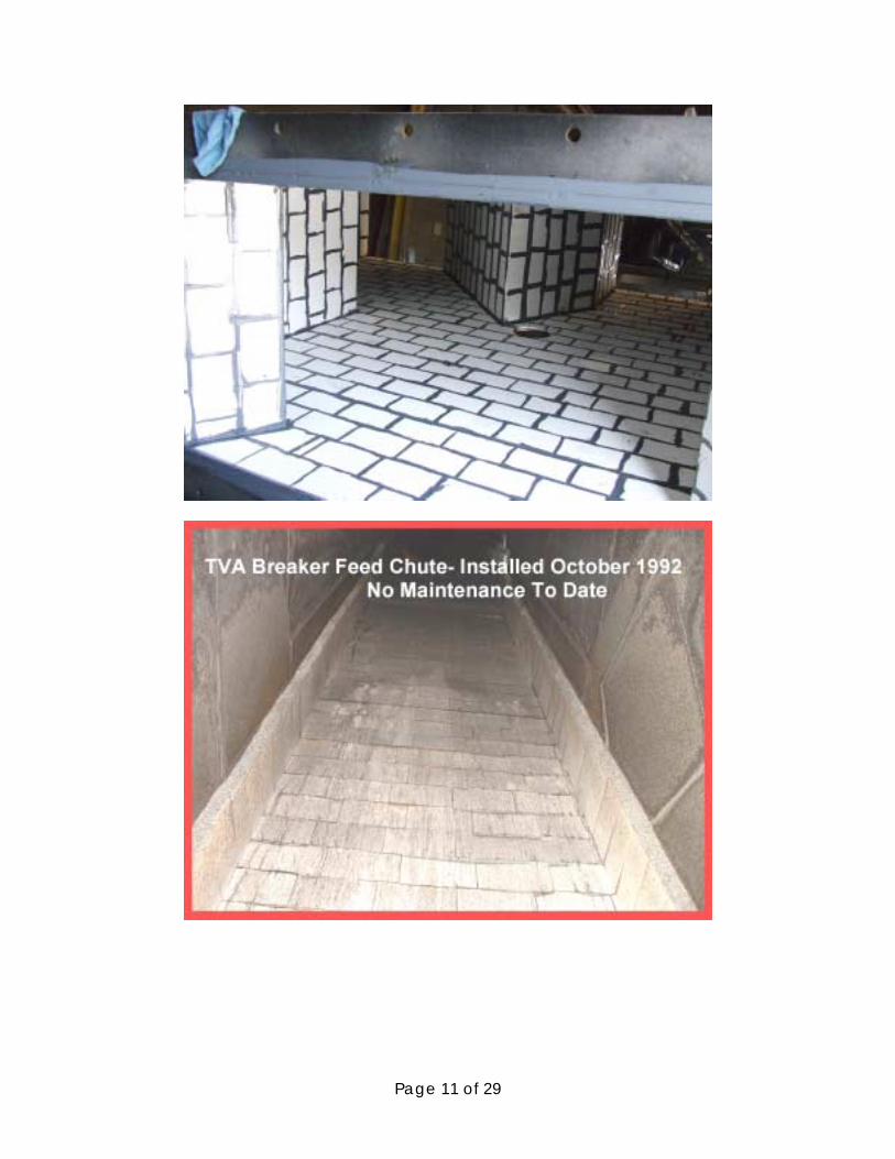
• ½” x 1 ¼” Gravity Flow in Chutework (Raw Coal and Refuse):
Less than 8 ft drop: ½” ceramic on sliding situations and 1” ceramic on sides
where there is impact, and in all bottoms.
Greater than 8 ft Drop: 2” ceramic on impact; elsewhere same as with “less
than 8 ft drop”.
• 1 ¼” x 3: Gravity flow in Chutework (Clean Coal): ½” ceramic on sides in sliding
conditions, 1” ceramic on sides where there is impact situations; 2” in bottoms where
there is impact, and step down to 1” ceramic once material is settled down into sliding.
(Exhibit E)
• 3” x 6”: Gravity flow in Chutework (Raw Coal and Refuse):
Less than 8 ft Drop: 1” ceramic on sides in sliding conditions and 2” ceramic on
impact areas. 2” on bottoms where there is impact and can step down to 1” ceramic once
materials are settled down in sliding.
Greater than 8 ft Drop: 1” ceramic on sides on sliding conditions, and 4”
ceramic in akll impact areas. 4” ceramic should be stepped down in bottom slides below
impact areas, and can even be stepped down to 1” ceramic once the material is settled
into sliding.

Page 13 of 29
• Greater than 6” (Raw Coal and Refuse):
Of course, this is the extreme application that many would be very skeptical and shy
away from ceramic liners. But we have found, through many of these operating
conditions that we have successfully tackled, that through design and proper application
we can meet this need consistently.
By studying the nature of the material, the amount of fines and clay mixed in, and the
amounts of force of the flows, we have come up with viable solutions. It involves
creative designs, utilizing 4” and 6” thick ceramic. The utilization of turn shelves where
applicable, and last but certainly not least, the utilization of “bolt-in” or “weld-in” impact
panels. We also recommend leading in edge barring with minimum of ¾” AR strips to
protect leading edges of ceramic and sufficient barring to maintain and hold monolithic
integrity of ceramic panel system.

Page 14 of 29
At Arch Coal’s Cumberland River Processing Plant, we designed a Raw Coal Chute
feeding the Raw Coal Stockpile, with 6” thick ceramic bolt-in pads. (Exhibit G)
Previously, the operation had extreme difficulty in maintaining a chute in this application.
The new chute has been in for nine months, and has held up extremely well. Whenever,
if ever there is a need to repair the chute, it will only involve bolting in new panels.
(Exhibit F)
Also, at Arch Coal’s Lone Mountain Processing Plant, the operator has a scalped rock
chute (rock up to 16”) feeding onto a collecting belt that was not only a constant
maintenance problem, but also a terrible noise problem. They had tried several different
wear resistant materials in the lower impact panel, but had found nothing to be
successful. We designed a 6” ceramic weldable impact pane that was installed. It solved
all their problems. Being in now for six months, the panels remains in excellent
condition, and is performing the job of transfer at a much lower decibel. (Exhibits G, H,
and I)

Page 15 of 29
• Another best practice “Rule of Thumb” is with ceramic lined ells, “Extend tangents off of
all ells by 1 ½ times the diameter of the pipe, beyond the radius.” Also, if the ell tangents
are designed equal lengths on each end of the ell, the operator will be able to rotate the ell
once the ceramic eventually wears (many years in the future).
When the ell is taken down to rotate, repair the worn section with ceramic beaded wear
compound and you will be able to obtain many more years without the cost of replacing
the ell.
Other Applications of Interest
• CTI Pump Adapters (Patented)
Our Pump Adapters utilized off the volute of pumping applications, eliminates the use of
“Bell Reducers” which have historically been a huge maintenance problem. By
maintaining the pump volute ID and swelling out to the larger pipe diameter in the main
flow (utilizing 1” and ½” ceramic linings), we have found that the pump adapters have
outlasted the “Bell Reducers” up to 20 times. (Exhibit J)

Page 16 of 29

Page 17 of 29
• Cyclone Tubs with Distributors (Exhibit K)
We advise that pump lines from cyclone pumps be straight and vertical, with bottom feed
to the distributor or top feed. Feed pipes should be lined with ½” or 1” tile and the tub
overflow should be lined with 1” Stonhard and #9 expanded metal.
The Cyclone Underflow side of tub should be lined with ½” ceramic on the bottom and
6” up the sides. Discharge stubs lined with ½” tile and overflow pipes from cyclones
made of schedule 80 or high density polyethylene piping, with feed inlet spools lined
with ½” ceramic. The distributor wall should be lined with ½” ceramic and the top to be
1” AR, bolt-in cover lid. All tangent feed lines lined with ½” tile.

Page 18 of 29
• Cyclones and Repairs (Exhibit L)
Most heavy media and classifying cyclones have engineered 1” and ½” ceramic liners.
We recommend new fabricated sections with engineered liner as needed, to rebuild to
original specifications.

Page 19 of 29
• Sumps-Heavy Media Pulping Columns (Exhibit M)
In sumps, pulping columns, kill boxes, and suction liners the application of ceramic has
become the required specification. We adhere to ½” ceramic inside the columns tube. In
some cases, 1” on the impact cones and kill box arrangements. Apply ½” ceramic in
suction lines. The lower 48” to 60” of the outside of the column is to have ½” ceramic
with the remainder lined with Stonhard.
Suction lines are normally fabricated out of standard wall pipe lined with ½” ceramic.
Best Practice Liners for the Sumps and Media Pulping Column: Heavy media sumps
12-14 ft diameter are normally fabricated in four pieces due to weight and shipping
restrictions. These are built in plant and flanged as an inner cross section to re-bolt once
onsite with minimum labor. The sump is lined with 1” Stonhard above sink elevations.

Page 20 of 29
½” ceramic is used in vertical column and sink column. Stonhard liner is applied to inner
cone to water line just below screen.

Page 21 of 29
• Non Radial Cyclone Feed Headers (Exhibit N)
When you need to feed a smaller number of classifying cyclones than is needed for a
round tub (normally less than four cyclones)-“Pipe Header Systems” are applicable and
give efficient distribution. This takes up very little area to install.
• Static Box Systems (Exhibit O) (Replacing Rotating Sieve Assemblies and Utilizing
Feeding Banana Screens)
These have proven to work very effectively in many applications, Deslime and HMC
Clean Coal and Refuse D&R Feed for Horizontal and Banana Screens. The feed headers

Page 22 of 29
are completely ceramic lined, and are designed to kill the velocity of the feed, and to give
great distribution onto the feed end of the screening.
• Rotating Distributors
These are essential to give efficient distribution of feed to multiple processing items (raw
coal, spirals, deslime screens, etc.). The inside of the distributors are completely ceramic
lined. Due to ceramic liners we are now able to restrict flow rates to a controlled flow-
Slower rates in some applications promote classification and media recovery.

Page 23 of 29
• Heavy Media Vessel Bottoms (Exhibit P)
We have lined three vessels in the past and have had great results. One application has
been in for over ten years! Ok maintenance planners, don’t you think it’s time to get
away from changing your vessel bottom liners every one to two years? We will point out
that Consol Energy installed a 2” bottom in their HM Washer at Robinson Run Prep Plant
and it is also performing to spec to date.
• Screen Underflow Pans (Exhibit Q)
In pans under Raw Coal and media D&R screens where high volumes are flowing it is
best to line the bottom of pans with ½”or 1” ceramic in the first 6ft to 8 ft and in the

Page 24 of 29
lower trough section. Stonhard can be used in other areas in most instances. Under raw
coal scalping screens, it is advisable to utilize 2” and 4” ceramic pad applications.
• Flume Systems Replacing Piping Networks (Exhibit R)
In many applications where you have a need of gravity flow, especially with multiple
converging pipes, it is advantageous to design ceramic lined “Flume Systems”. A prime
example of applying this: carrying the products off of the spirals.

Page 25 of 29
• Innovative Design and Utilization of New Computer Technologies (Exhibit S)
3-D CAD capabilities have become a tremendous aid in proving designs. These new
tools allow the designer to identify potential problems with a greater degree of accuracy,
allowing correction out front, instead of after the fact. Modeling capabilities along with

Page 26 of 29
new cutting technology allow us to continually improve the design to flow criteria that
now support 24/7 schedules of our operations.
• Last, but not least, “Noise Reduction” and “Clean Housekeeping”
A huge benefit of a ceramic program that is often not appreciated is the degree that plant
noise decibels is lowered. Raw coal and refuse flows can create decibel levels that can

Page 27 of 29
damage your hearing permanently, impact energy levels in you work force, complicate
communications, and contribute to a poor work environment making your work force
irritable at best.
Ceramic applications dissipate the load and do not amplify the noise energy created by
coal flows.
Facing the onslaught of political pressure and the overall media babble as to coal
operations being poorly kept, federal and state inspectors show little compassion for
operators that maintain poor operations. Fines and closer orders are a common direct
expense occurring in coal operations.
This kind of attention creates a domino effect that increases cost, exponentially, and adds
to the direct cost of lost production.
Having a good ceramic program in place will deliver a tremendous return as to fewer
hours expended on cleanup and a better focus on production. Bringing all the elements
together to combat the political and operational realities will result in overall improved
operational performance creating a more positive work force that takes pride in their
operation.
Conclusion
As designers, fabricators, and product suppliers, we feel that we are in partnership with you as
the coal operators. We have learned from each other. A major part of our lives, like yours, is the
coal industry. We have outlined a program that is a conservative estimate of a 15 to 1 return on
Page 28 of 29
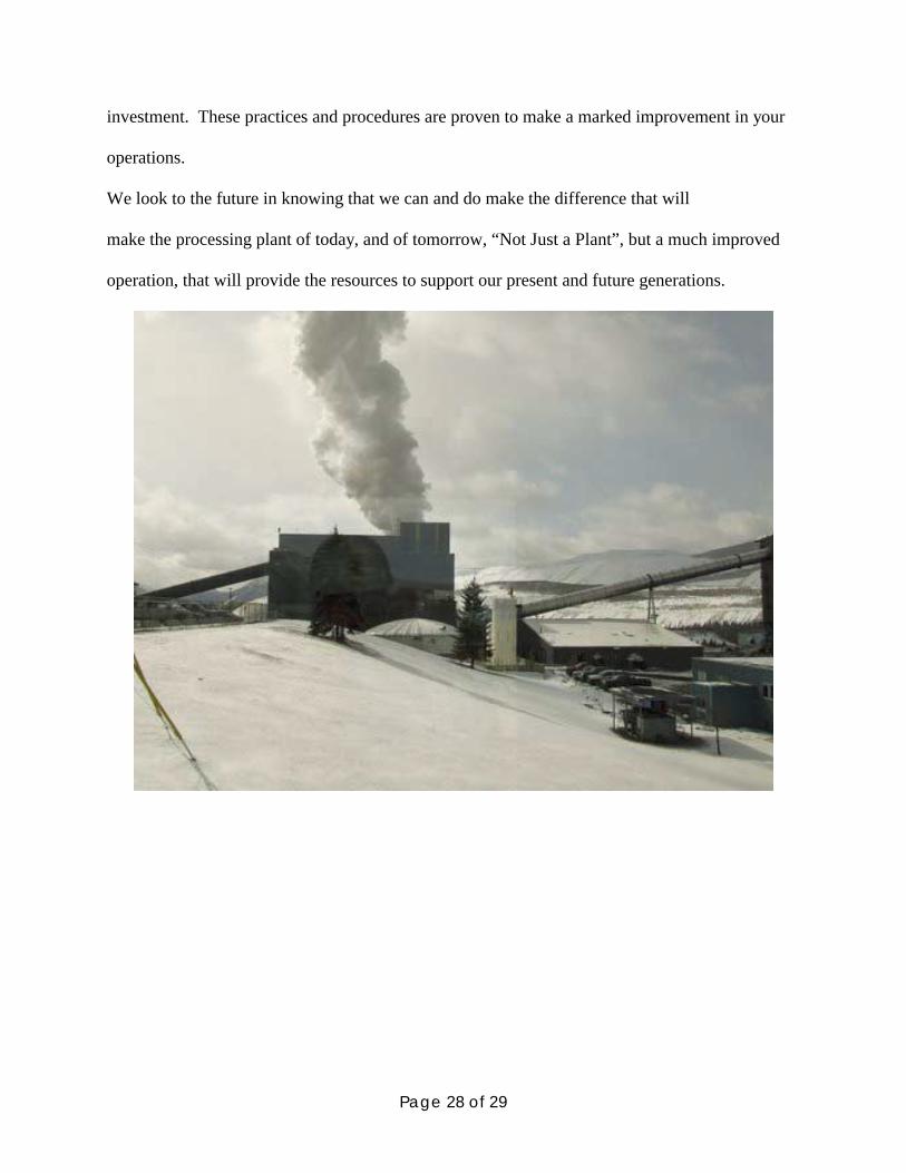
investment. These practices and procedures are proven to make a marked improvement in your
operations.
We look to the future in knowing that we can and do make the difference that will
make the processing plant of today, and of tomorrow, “Not Just a Plant”, but a much improved
operation, that will provide the resources to support our present and future generations.

Page 29 of 29
References
“Physical and Mechanical Properties of Materials.” 19 October 2007. Omega Slate. 2000.
http://www.omegaslate.com/mechanic.htm.
“What is Ceramic.” 19 October 2007.
http://www.acers.org/acers/aboutceramic.asp?id=outreach#Definition.
“Your Questions Answered.” 19 October 2007. Omega Slate. 2000.
http://www.omegaslate.com/question.htm.