the university of missouri research … university of missouri research reactor heu to leu...
TRANSCRIPT

THE UNIVERSITY OF MISSOURI RESEARCH REACTOR
HEU TO LEU CONVERSION PROJECT STATUS
L. Foyto, K. Kutikkad, J. C. McKibben and N. Peters
University of Missouri-Columbia Research Reactor
1513 Research Park Drive, Columbia, Missouri 65211 – USA
E. Feldman, J. Stevens and J. Stillman
Argonne National Laboratory
9700 South Cass Avenue, Argonne, Illinois 60439 – USA
Presented at the 2012 International Meeting
on Reduced Enrichment for Research and Test Reactors
October 14-17, 2012
Warsaw, Poland
DISCLAIMER
This report was prepared as an account of work sponsored by an agency of the United States Government. Neither the United States Government nor any agency thereof, nor UChicago Argonne, LLC, nor any of their employees or officers, makes any warranty, express or implied, or assumes any legal liability or responsibility for the accuracy, completeness, or usefulness of any information, apparatus, product, or process disclosed, or represents that its use would not infringe privately owned rights. Reference herein to any specific commercial product, process, or service by trade name, trademark, manufacturer, or otherwise, does not necessarily constitute or imply its endorsement, recommendation, or favoring by the United States Government or any agency thereof. The views and opinions of document authors expressed herein do not necessarily state or reflect those of the United States Government or any agency thereof, Argonne National Laboratory, or UChicago Argonne, LLC.

RERTR 2012 ― 34th
INTERNATIONAL MEETING ON
REDUCED ENRICHMENT FOR RESEARCH AND TEST REACTORS
October 14-17, 2012
Warsaw Marriott Hotel
Warsaw, Poland
The University of Missouri Research Reactor
HEU to LEU Fuel Conversion Project Status
L. Foyto, K. Kutikkad, J. C. McKibben and N. Peters
University of Missouri-Columbia Research Reactor
1513 Research Park Drive, Columbia, Missouri 65211 – USA
and
E. Feldman, J. Stevens and J. Stillman
Argonne National Laboratory
9700 South Cass Avenue, Argonne, Illinois 60439 – USA
ABSTRACT
The University of Missouri Research Reactor (MURR®) is one of five U.S. high
performance research and test reactors that are actively collaborating with the Global
Threat Reduction Initiative (GTRI) Reduced Enrichment for Research and Test Reactors
(RERTR) Program to find a suitable low-enriched uranium (LEU) fuel replacement for
the currently required highly-enriched uranium (HEU) fuel. A conversion feasibility
study, based on U-10Mo monolithic LEU fuel, was completed in 2009. It was concluded
that the proposed feasibility study design (FSD) fuel assembly, in conjunction with an
increase in power level from 10 to approximately 12 MWth, would (1) maintain safety
margins during operation, (2) allow operating fuel cycle lengths to be maintained for
efficient and effective use of the facility, and (3) preserve an acceptable level and
spectrum of key neutron fluxes to meet the scientific mission of the facility.
The “Preliminary Safety Analysis Report Methodologies and Scenarios for LEU
Conversion of MURR,” completed in June 2011, documented the FSD LEU fuel assembly
design parameter values critical to the Fuel Development (FD), Fuel Fabrication
Capability (FFC) and Hydromechanical Fuel Test Facility (HMFTF) pillars of the GTRI
Conversion Program. Knowledge gained by the FD and FFC pillars within the past year
revealed that the initial assumptions regarding design constraints on the LEU fuel plates
needed to be adjusted. In particular, the cladding surrounding the fuel foils in the FSD
LEU fuel assembly was designed as thin as 10 mil (nominal). Experience has shown that
in order to reliably fabricate fuel plates with U-10Mo monolithic foil, the nominal clad
thickness should be no thinner than 12 mil.
Working with MURR staff, the Reactor Conversion (RC) pillar has responded to this
feedback by redesigning the LEU fuel assembly to meet this constraint. An extensive
series of “contingency designs” were evaluated through scoping studies, followed by
optimization of a design (CD35) that meets the conversion goals. The newly designed
LEU fuel assembly that is now proposed is constructed with fewer fuel plates and a
thicker nominal clad thickness than the FSD. Two Argonne National Laboratory (ANL)
technical reports – Core Neutron Physics and Steady-State Thermal-Hydraulic Analysis –
have been developed which provide the steady-state safety bases and a comparison of the
FSD, CD35 and HEU fuel assemblies. These documents, which are the foundation to
developing Chapter 4, “Reactor Description,” of the LEU Conversion Safety Analysis
Report (SAR), will be discussed.
1. INTRODUCTION
Because of its compact core design (33 liters), which requires a very high loading density of 235
U, the University of Missouri Research Reactor (MURR®) could not perform its mission with
any previously qualified low-enriched uranium (LEU) fuels. However, in 2006 with the prospect
of the Global Threat Reduction Initiative (GTRI) Fuel Development (FD) Program validating the
performance of U-10Mo monolithic LEU foil fuels, MURR began actively collaborating with the
GTRI Conversion Program, and four other U.S. high-performance research and test reactors that
use highly-enriched uranium (HEU) fuel, to find a suitable LEU fuel replacement. This paper
provides the current status of converting the MURR from an aluminide dispersion HEU fuel to a
U-10Mo monolithic LEU fuel.
2. DESCRIPTION OF FACILITY, REACTOR AND FUEL
2.1 General Facility Description
The MURR is a multi-disciplinary research and education
facility providing a broad range of analytical and
irradiation services to the research community and the
commercial sector. The MURR has six types of
experimental facilities designed to support these services
and research programs: the center test hole (flux trap); the
pneumatic tube system; the graphite reflector region; the
bulk pool; the (six) beamports; and the thermal column.
The first four facilities provide areas for the placement of
sample holders, or carriers, in different regions of the
reactor core assembly for the purposes of material
irradiation. Some of the material irradiation services
include transmutation doping of silicon, isotope production
for the development of radiopharmaceuticals and other life-
science research, and neutron activation analysis. The six
beamports channel neutron radiation from the reactor core to experimental equipment which is
used primarily to determine the structure of solids and liquids through neutron scattering and to
perform Boron Neutron Capture Therapy (BNCT) experiments.
2.2 Basic Reactor Description
The MURR is a pressurized, reflected (beryllium and graphite), heterogeneous, open pool-type
reactor, which is light-water moderated and cooled. The reactor is designed and licensed to
operate at a maximum thermal power level of 10 MW with forced cooling, or up to 50 kW in the
natural convection mode.
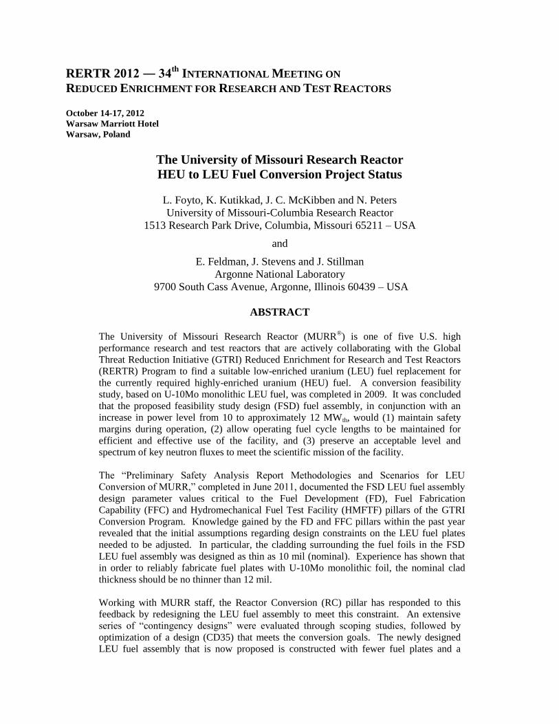
Figure 2.1
MCNP Model of Current Core
Configuration
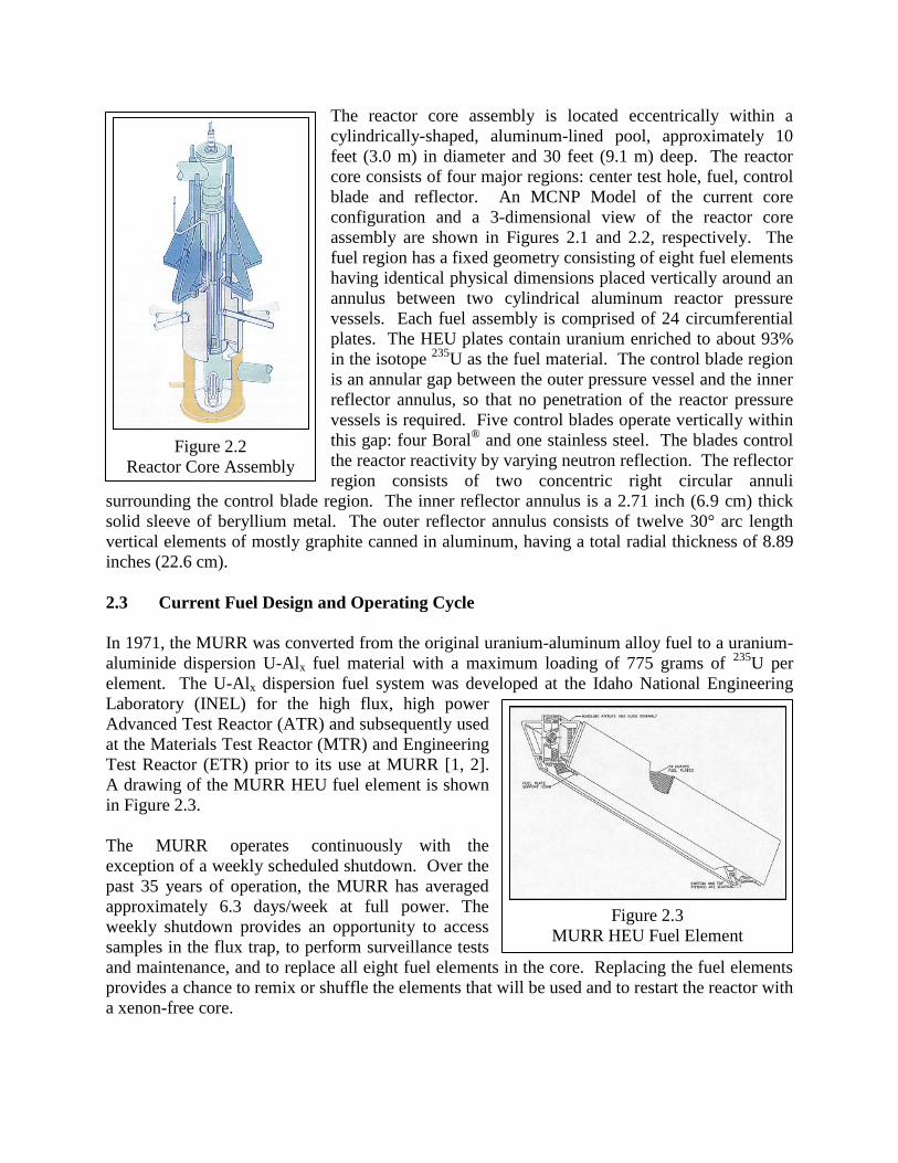
Figure 2.3
MURR HEU Fuel Element
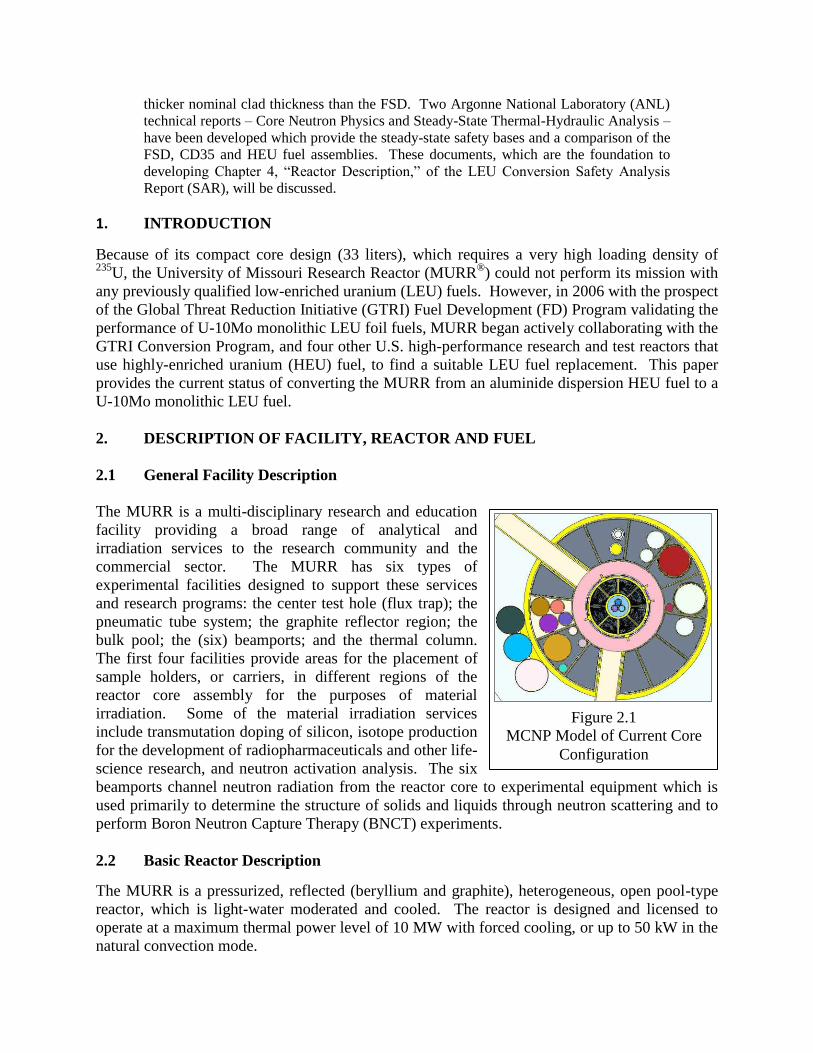
The reactor core assembly is located eccentrically within a
cylindrically-shaped, aluminum-lined pool, approximately 10
feet (3.0 m) in diameter and 30 feet (9.1 m) deep. The reactor
core consists of four major regions: center test hole, fuel, control
blade and reflector. An MCNP Model of the current core
configuration and a 3-dimensional view of the reactor core
assembly are shown in Figures 2.1 and 2.2, respectively. The
fuel region has a fixed geometry consisting of eight fuel elements
having identical physical dimensions placed vertically around an
annulus between two cylindrical aluminum reactor pressure
vessels. Each fuel assembly is comprised of 24 circumferential
plates. The HEU plates contain uranium enriched to about 93%
in the isotope 235
U as the fuel material. The control blade region
is an annular gap between the outer pressure vessel and the inner
reflector annulus, so that no penetration of the reactor pressure
vessels is required. Five control blades operate vertically within
this gap: four Boral® and one stainless steel. The blades control
the reactor reactivity by varying neutron reflection. The reflector
region consists of two concentric right circular annuli
surrounding the control blade region. The inner reflector annulus is a 2.71 inch (6.9 cm) thick
solid sleeve of beryllium metal. The outer reflector annulus consists of twelve 30° arc length
vertical elements of mostly graphite canned in aluminum, having a total radial thickness of 8.89
inches (22.6 cm).
2.3 Current Fuel Design and Operating Cycle
In 1971, the MURR was converted from the original uranium-aluminum alloy fuel to a uranium-
aluminide dispersion U-Alx fuel material with a maximum loading of 775 grams of 235
U per
element. The U-Alx dispersion fuel system was developed at the Idaho National Engineering
Laboratory (INEL) for the high flux, high power
Advanced Test Reactor (ATR) and subsequently used
at the Materials Test Reactor (MTR) and Engineering
Test Reactor (ETR) prior to its use at MURR [1, 2].
A drawing of the MURR HEU fuel element is shown
in Figure 2.3.
The MURR operates continuously with the
exception of a weekly scheduled shutdown. Over the
past 35 years of operation, the MURR has averaged
approximately 6.3 days/week at full power. The
weekly shutdown provides an opportunity to access
samples in the flux trap, to perform surveillance tests
and maintenance, and to replace all eight fuel elements in the core. Replacing the fuel elements
provides a chance to remix or shuffle the elements that will be used and to restart the reactor with
a xenon-free core.
Figure 2.2
Reactor Core Assembly
3. LEU FUEL STEADY-STATE SAFETY BASIS
The LEU fuel element design developed in the Feasibility Study [3] was constructed similar to
the HEU fuel element, with 24 fuel plates, but with thinner fuel foil thicknesses for the plates
near the flux trap and the beryllium reflector to flatten the radial heat flux profile. The study
showed that the “FSD” (Feasibility Study Design) fuel element met the thermal-hydraulic safety
and shutdown margins for the MURR; maintained the experimental performance of the facility –
provided the reactor power level could be uprated from 10 to 12 MW; and yielded a decrease in
the number of fuel elements needed per year to maintain the reactor’s weekly operating schedule.
Following the release of the Feasibility Study and the Preliminary Safety Analysis Report
(PSAR) [4], experience gained by the FD and Fuel Fabrication Capability (FFC) pillars of the
GTRI Conversion Program revealed that initial assumptions regarding design constraints on the
LEU plates needed to be adjusted. In particular, the clad, which consists of Al-6061 aluminum
and a thin (1 mil) zirconium layer at the fuel-aluminum interface, surrounding the U-10Mo fuel
foils in the FSD was designed as thin as 10 mil (nominal). However, recent experience has
shown that in order to reliably fabricate the fuel plates with U-10Mo fuel foils, the nominal clad
thickness should be no thinner than 12 mil.
The Reactor Conversion (RC) pillar responded to this feedback by redesigning the LEU fuel
element to meet this constraint [5]. Any design modification affects not only the fuel reactivity
and achievable discharge burnup, but also the core power distribution. This is highly important,
as the steady-state thermal-hydraulic safety analyses are required to show sufficient margins to
the onset of flow instability (FI) and critical heat flux (CHF) at the reactor’s Limiting Safety
System Setting (LSSS) conditions. From preliminary calculations it appears that MURR will be
limited by a margin to FI. This margin is generally influenced by the axially-averaged hot-stripe
heat flux in the core. Changing the width of the coolant channels can also have an impact on the
safety margins.
An extensive series of “contingency designs” were evaluated through scoping studies, followed
by optimization of a design that satisfies the conversion goals of meeting thermal-hydraulic
safety and shutdown margins while maintaining experimental performance. The newly designed
fuel element that is now proposed has been labeled “CD35” (Contingency Design number 35)
and is constructed with 23 fuel plates (instead of 24 plates as in the FSD and HEU fuel
elements). The element still uses graded foil thicknesses to flatten the radial heat flux profile,
but the thinnest nominal clad is 12 mil (versus 10 mil in the FSD) and the thinnest total plate
thickness is 44 mil (versus 38 mil in the FSD).
4. CORE NEUTRON PHYSICS ANALYSIS
4.1 Development of the LEU Fuel Element
Fuel performance and power distribution calculations for LEU fuel designs were performed
using neutron physics codes and models validated for analyses of the MURR [3, 5]. An
illustration of the reactor core under current conditions is shown above in Figure 2.1. A REBUS-
DIF3D [6] model was used for fuel cycle simulation and fuel burnup calculations. The depleted
compositions calculated by REBUS-DIF3D were then used in an MCNP [7] model for detailed
power distribution analyses for all fresh and mixed-burnup cores. The MCNP power
distributions calculated for the MURR fuel elements are based on a plate-by-plate discretization
with axial and azimuthal zones.
One of the key features contributing to the success of the FSD element design was increasing the
water-to-fuel ratio relative to the HEU element design in order to maintain the core reactivity.
This was accomplished by reducing the thickness of all the fuel plates so that less water was
displaced. This enabled the coolant channels between adjacent fuel plates to increase in width
from 80 mil for the HEU element to 92 mil for the FSD.
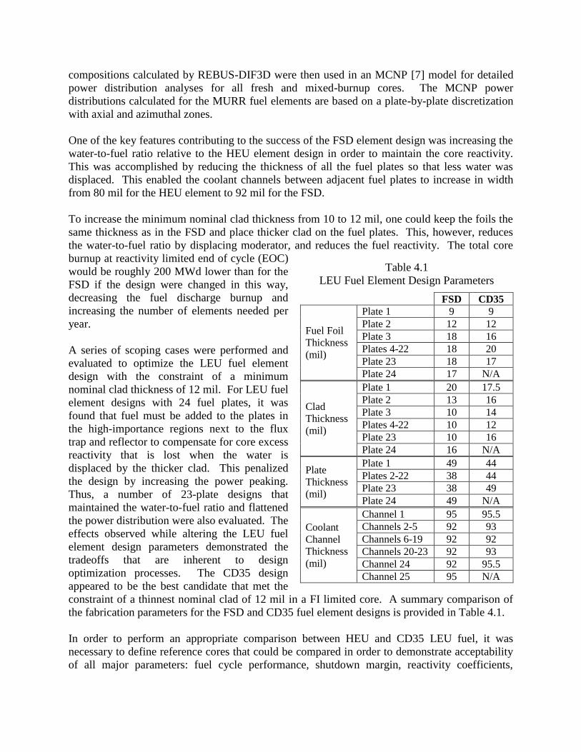
To increase the minimum nominal clad thickness from 10 to 12 mil, one could keep the foils the
same thickness as in the FSD and place thicker clad on the fuel plates. This, however, reduces
the water-to-fuel ratio by displacing moderator, and reduces the fuel reactivity. The total core
burnup at reactivity limited end of cycle (EOC)
would be roughly 200 MWd lower than for the
FSD if the design were changed in this way,
decreasing the fuel discharge burnup and
increasing the number of elements needed per
year.
A series of scoping cases were performed and
evaluated to optimize the LEU fuel element
design with the constraint of a minimum
nominal clad thickness of 12 mil. For LEU fuel
element designs with 24 fuel plates, it was
found that fuel must be added to the plates in
the high-importance regions next to the flux
trap and reflector to compensate for core excess
reactivity that is lost when the water is
displaced by the thicker clad. This penalized
the design by increasing the power peaking.
Thus, a number of 23-plate designs that
maintained the water-to-fuel ratio and flattened
the power distribution were also evaluated. The
effects observed while altering the LEU fuel
element design parameters demonstrated the
tradeoffs that are inherent to design
optimization processes. The CD35 design
appeared to be the best candidate that met the
constraint of a thinnest nominal clad of 12 mil in a FI limited core. A summary comparison of
the fabrication parameters for the FSD and CD35 fuel element designs is provided in Table 4.1.
In order to perform an appropriate comparison between HEU and CD35 LEU fuel, it was
necessary to define reference cores that could be compared in order to demonstrate acceptability
of all major parameters: fuel cycle performance, shutdown margin, reactivity coefficients,
Table 4.1
LEU Fuel Element Design Parameters
FSD CD35
Fuel Foil
Thickness
(mil)
Plate 1 9 9
Plate 2 12 12
Plate 3 18 16
Plates 4-22 18 20
Plate 23 18 17
Plate 24 17 N/A
Clad
Thickness
(mil)
Plate 1 20 17.5
Plate 2 13 16
Plate 3 10 14
Plates 4-22 10 12
Plate 23 10 16
Plate 24 16 N/A
Plate
Thickness
(mil)
Plate 1 49 44
Plates 2-22 38 44
Plate 23 38 49
Plate 24 49 N/A
Coolant
Channel
Thickness
(mil)
Channel 1 95 95.5
Channels 2-5 92 93
Channels 6-19 92 92
Channels 20-23 92 93
Channel 24 92 95.5
Channel 25 95 N/A .
thermal-hydraulic steady-state safety margins and experimental performance. These reference
cores should be close to limiting in order to provide additional confidence that the safety margin
calculations treat the potentially limiting power shapes from the HEU and CD35 fuel elements.
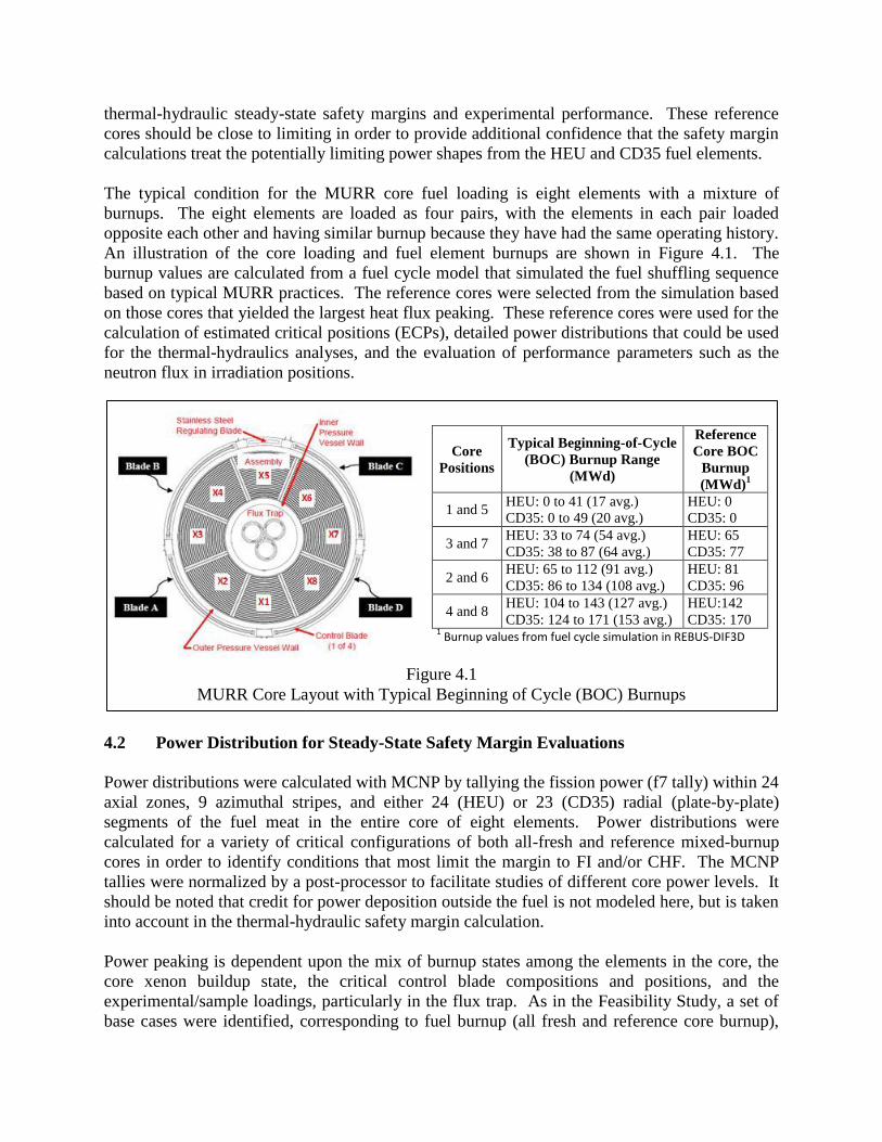
The typical condition for the MURR core fuel loading is eight elements with a mixture of
burnups. The eight elements are loaded as four pairs, with the elements in each pair loaded
opposite each other and having similar burnup because they have had the same operating history.
An illustration of the core loading and fuel element burnups are shown in Figure 4.1. The
burnup values are calculated from a fuel cycle model that simulated the fuel shuffling sequence
based on typical MURR practices. The reference cores were selected from the simulation based
on those cores that yielded the largest heat flux peaking. These reference cores were used for the
calculation of estimated critical positions (ECPs), detailed power distributions that could be used
for the thermal-hydraulics analyses, and the evaluation of performance parameters such as the
neutron flux in irradiation positions.
4.2 Power Distribution for Steady-State Safety Margin Evaluations
Power distributions were calculated with MCNP by tallying the fission power (f7 tally) within 24
axial zones, 9 azimuthal stripes, and either 24 (HEU) or 23 (CD35) radial (plate-by-plate)
segments of the fuel meat in the entire core of eight elements. Power distributions were
calculated for a variety of critical configurations of both all-fresh and reference mixed-burnup
cores in order to identify conditions that most limit the margin to FI and/or CHF. The MCNP
tallies were normalized by a post-processor to facilitate studies of different core power levels. It
should be noted that credit for power deposition outside the fuel is not modeled here, but is taken
into account in the thermal-hydraulic safety margin calculation.
Power peaking is dependent upon the mix of burnup states among the elements in the core, the
core xenon buildup state, the critical control blade compositions and positions, and the
experimental/sample loadings, particularly in the flux trap. As in the Feasibility Study, a set of
base cases were identified, corresponding to fuel burnup (all fresh and reference core burnup),
Figure 4.1
MURR Core Layout with Typical Beginning of Cycle (BOC) Burnups
Core
Positions
Typical Beginning-of-Cycle
(BOC) Burnup Range
(MWd)
Reference
Core BOC
Burnup
(MWd)1
1 and 5 HEU: 0 to 41 (17 avg.)
CD35: 0 to 49 (20 avg.)
HEU: 0
CD35: 0
3 and 7 HEU: 33 to 74 (54 avg.)
CD35: 38 to 87 (64 avg.)
HEU: 65
CD35: 77
2 and 6 HEU: 65 to 112 (91 avg.)
CD35: 86 to 134 (108 avg.)
HEU: 81
CD35: 96
4 and 8 HEU: 104 to 143 (127 avg.)
CD35: 124 to 171 (153 avg.)
HEU:142
CD35: 170 1 Burnup values from fuel cycle simulation in REBUS-DIF3D

core xenon buildup state (no Xe and equilibrium Xe), and flux trap sample loading (typical
samples and an off-nominal “empty trap” case).
Furthermore, the cores for each fuel type (HEU and CD35) were evaluated under various
conditions with regard to blade depletion and positioning. In the base case, it was assumed that
the control blades were at their fresh composition and banked in position. Additionally, the
effect of 10
B concentration in the blades due to depletion [8] and mismatched positioning of the
blades on the core power distribution was examined since variations of this sort can exist in
MURR. The differences in the 10
B concentration at the tip of the shim blades can create a tilt in
the core power distribution, and the MURR Technical Specifications (TS) allow for the height of
the blade tips to be mismatched by up to one inch. Therefore, as an extreme scenario, perturbed
heat flux profiles were calculated with two of the blades at their end-of-life (8 years) and
positioned one inch above the other two blades, which were assumed to be fresh.
Consequently, power distributions for each fuel type were calculated for 24 cases (2 fuel burnups
x 2 Xe states x 2 flux trap states x 3 control blade states) that enveloped the distinct combinations
of effects. The atom densities of the fuel compositions for each core state were read from
REBUS-DIF3D depletion results to automatically update an MCNP input file. A search was
then performed with MCNP to find the critical blade position for the core (i.e., blades moved
until MCNP predicted a keff of 1.0). Finally, a post-processor was applied to read the mctal file
and produce power distribution edits suitable for the thermal-hydraulic analyses of FI and CHF.
Figure 4.2 plots the average heat
flux for each plate of each element
for the CD35 core Case 8A2. The
conditions for this case are a
reference mixed-core burnup as
noted in Figure 4.1, equilibrium Xe,
the flux trap loaded with typical
samples, and control blades A and
D at the depleted composition and
positioned 1 inch higher than blades
B and C. The largest average plate
heat flux for this case is in plate 23
(outermost plate) of the element in
core position 1 (fresh element). The
radial shape of the heat flux in the
figure illustrates the important
effect of moderation and fissile material self-shielding, as well as the choice of fuel foil thickness
for reducing the heat flux peaking. The inner and outermost plates in the MURR tend to have a
much higher heat flux (i.e., fission rate) due to their proximity to the heavily-moderated flux trap
(plate 1) and reflectors (plate 23 for the CD35 design). The interior plates have a lower heat flux
due to both less moderation from the coolant channels and the self-shielding effect of outboard
plates consuming thermal neutrons coming from the flux trap and reflector regions. As indicated
in the figure, the fuel foils in the inner and outermost plates are thinned relative to the interior
Figure 4.2
Average Heat Flux in Each Plate of Each Element
in CD35 Core Case 8A2
9
12
16
17
Fuel foil thickness 20 mil unless otherwise indicated
plates in order to prevent extremely high heat flux peaking which would reduce the margin to FI
(as well as the margin to CHF).
The power distribution varies significantly in the radial and axial directions, but it also varies
along the width of the fuel meat. There is a 70 mil wide unfueled region of the fuel plates
adjacent to the side plates. Consequently, the fuel near the side plates sees relatively more
moderation and less self-shielding than the fuel near the middle of the plate. The moderation
effect on the power peaking along the fueled edge is most pronounced for plates 5-22, which
have azimuthal peaking factors of 1.17 to 1.35. The azimuthal effect is smaller for the outboard
plates. For plate 1, the azimuthal peaking factor is < 1.05, while for plate 23 the peaking factor
is < 1.16.
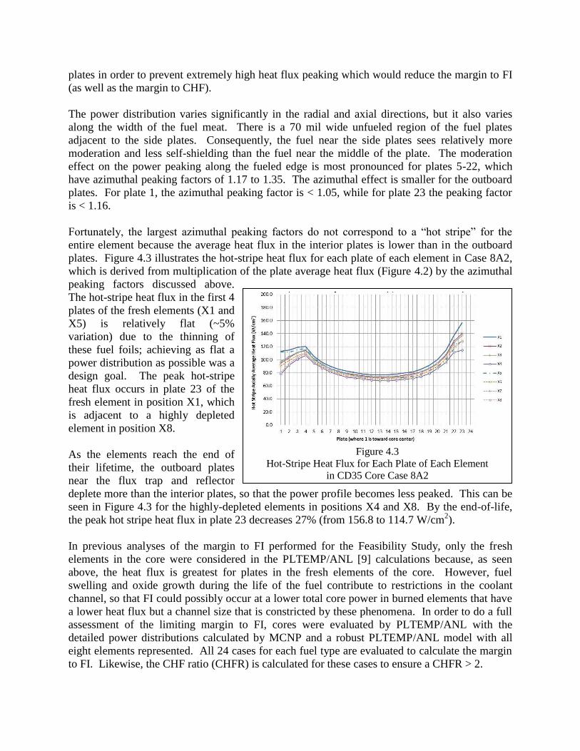
Fortunately, the largest azimuthal peaking factors do not correspond to a “hot stripe” for the
entire element because the average heat flux in the interior plates is lower than in the outboard
plates. Figure 4.3 illustrates the hot-stripe heat flux for each plate of each element in Case 8A2,
which is derived from multiplication of the plate average heat flux (Figure 4.2) by the azimuthal
peaking factors discussed above.
The hot-stripe heat flux in the first 4
plates of the fresh elements (X1 and
X5) is relatively flat (~5%
variation) due to the thinning of
these fuel foils; achieving as flat a
power distribution as possible was a
design goal. The peak hot-stripe
heat flux occurs in plate 23 of the
fresh element in position X1, which
is adjacent to a highly depleted
element in position X8.
As the elements reach the end of
their lifetime, the outboard plates
near the flux trap and reflector
deplete more than the interior plates, so that the power profile becomes less peaked. This can be
seen in Figure 4.3 for the highly-depleted elements in positions X4 and X8. By the end-of-life,
the peak hot stripe heat flux in plate 23 decreases 27% (from 156.8 to 114.7 W/cm2).
In previous analyses of the margin to FI performed for the Feasibility Study, only the fresh
elements in the core were considered in the PLTEMP/ANL [9] calculations because, as seen
above, the heat flux is greatest for plates in the fresh elements of the core. However, fuel
swelling and oxide growth during the life of the fuel contribute to restrictions in the coolant
channel, so that FI could possibly occur at a lower total core power in burned elements that have
a lower heat flux but a channel size that is constricted by these phenomena. In order to do a full
assessment of the limiting margin to FI, cores were evaluated by PLTEMP/ANL with the
detailed power distributions calculated by MCNP and a robust PLTEMP/ANL model with all
eight elements represented. All 24 cases for each fuel type are evaluated to calculate the margin
to FI. Likewise, the CHF ratio (CHFR) is calculated for these cases to ensure a CHFR > 2.
Figure 4.3
Hot-Stripe Heat Flux for Each Plate of Each Element
in CD35 Core Case 8A2
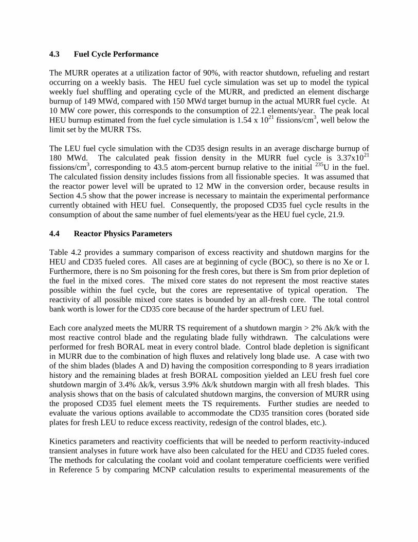
4.3 Fuel Cycle Performance
The MURR operates at a utilization factor of 90%, with reactor shutdown, refueling and restart
occurring on a weekly basis. The HEU fuel cycle simulation was set up to model the typical
weekly fuel shuffling and operating cycle of the MURR, and predicted an element discharge
burnup of 149 MWd, compared with 150 MWd target burnup in the actual MURR fuel cycle. At
10 MW core power, this corresponds to the consumption of 22.1 elements/year. The peak local
HEU burnup estimated from the fuel cycle simulation is 1.54 x 10²¹
fissions/cm3, well below the
limit set by the MURR TSs.
The LEU fuel cycle simulation with the CD35 design results in an average discharge burnup of
180 MWd. The calculated peak fission density in the MURR fuel cycle is 3.37x10²¹
fissions/cm3, corresponding to 43.5 atom-percent burnup relative to the initial
235U in the fuel.
The calculated fission density includes fissions from all fissionable species. It was assumed that
the reactor power level will be uprated to 12 MW in the conversion order, because results in
Section 4.5 show that the power increase is necessary to maintain the experimental performance
currently obtained with HEU fuel. Consequently, the proposed CD35 fuel cycle results in the
consumption of about the same number of fuel elements/year as the HEU fuel cycle, 21.9.
4.4 Reactor Physics Parameters
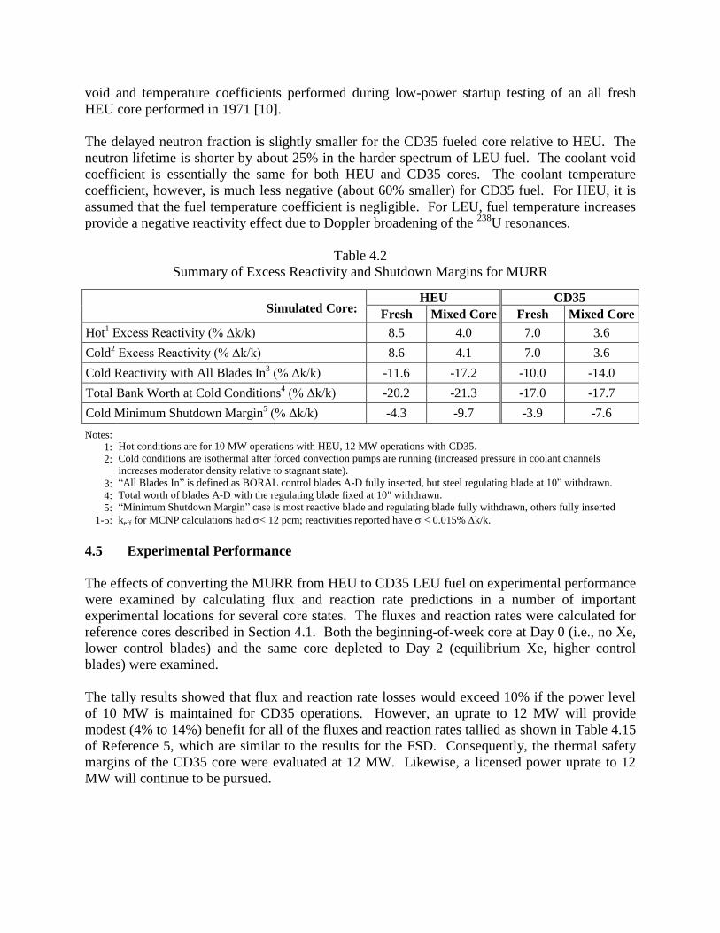
Table 4.2 provides a summary comparison of excess reactivity and shutdown margins for the
HEU and CD35 fueled cores. All cases are at beginning of cycle (BOC), so there is no Xe or I.
Furthermore, there is no Sm poisoning for the fresh cores, but there is Sm from prior depletion of
the fuel in the mixed cores. The mixed core states do not represent the most reactive states
possible within the fuel cycle, but the cores are representative of typical operation. The
reactivity of all possible mixed core states is bounded by an all-fresh core. The total control
bank worth is lower for the CD35 core because of the harder spectrum of LEU fuel.
Each core analyzed meets the MURR TS requirement of a shutdown margin > 2% Δk/k with the
most reactive control blade and the regulating blade fully withdrawn. The calculations were
performed for fresh BORAL meat in every control blade. Control blade depletion is significant
in MURR due to the combination of high fluxes and relatively long blade use. A case with two
of the shim blades (blades A and D) having the composition corresponding to 8 years irradiation
history and the remaining blades at fresh BORAL composition yielded an LEU fresh fuel core
shutdown margin of 3.4% Δk/k, versus 3.9% Δk/k shutdown margin with all fresh blades. This
analysis shows that on the basis of calculated shutdown margins, the conversion of MURR using
the proposed CD35 fuel element meets the TS requirements. Further studies are needed to
evaluate the various options available to accommodate the CD35 transition cores (borated side
plates for fresh LEU to reduce excess reactivity, redesign of the control blades, etc.).
Kinetics parameters and reactivity coefficients that will be needed to perform reactivity-induced
transient analyses in future work have also been calculated for the HEU and CD35 fueled cores.
The methods for calculating the coolant void and coolant temperature coefficients were verified
in Reference 5 by comparing MCNP calculation results to experimental measurements of the
void and temperature coefficients performed during low-power startup testing of an all fresh
HEU core performed in 1971 [10].
The delayed neutron fraction is slightly smaller for the CD35 fueled core relative to HEU. The
neutron lifetime is shorter by about 25% in the harder spectrum of LEU fuel. The coolant void
coefficient is essentially the same for both HEU and CD35 cores. The coolant temperature
coefficient, however, is much less negative (about 60% smaller) for CD35 fuel. For HEU, it is
assumed that the fuel temperature coefficient is negligible. For LEU, fuel temperature increases
provide a negative reactivity effect due to Doppler broadening of the 238
U resonances.
Table 4.2
Summary of Excess Reactivity and Shutdown Margins for MURR
Simulated Core: HEU CD35
Fresh Mixed Core Fresh Mixed Core
Hot1 Excess Reactivity (% Δk/k) 8.5 4.0 7.0 3.6
Cold2 Excess Reactivity (% Δk/k) 8.6 4.1 7.0 3.6
Cold Reactivity with All Blades In3 (% Δk/k) -11.6 -17.2 -10.0 -14.0
Total Bank Worth at Cold Conditions4 (% Δk/k) -20.2 -21.3 -17.0 -17.7
Cold Minimum Shutdown Margin5 (% Δk/k) -4.3 -9.7 -3.9 -7.6
Notes:
1:
2:
3:
4:
5:
1-5:
Hot conditions are for 10 MW operations with HEU, 12 MW operations with CD35.
Cold conditions are isothermal after forced convection pumps are running (increased pressure in coolant channels
increases moderator density relative to stagnant state).
“All Blades In” is defined as BORAL control blades A-D fully inserted, but steel regulating blade at 10” withdrawn.
Total worth of blades A-D with the regulating blade fixed at 10" withdrawn.
“Minimum Shutdown Margin” case is most reactive blade and regulating blade fully withdrawn, others fully inserted
keff for MCNP calculations had < 12 pcm; reactivities reported have< 0.015% k/k.
4.5 Experimental Performance
The effects of converting the MURR from HEU to CD35 LEU fuel on experimental performance
were examined by calculating flux and reaction rate predictions in a number of important
experimental locations for several core states. The fluxes and reaction rates were calculated for
reference cores described in Section 4.1. Both the beginning-of-week core at Day 0 (i.e., no Xe,
lower control blades) and the same core depleted to Day 2 (equilibrium Xe, higher control
blades) were examined.
The tally results showed that flux and reaction rate losses would exceed 10% if the power level
of 10 MW is maintained for CD35 operations. However, an uprate to 12 MW will provide
modest (4% to 14%) benefit for all of the fluxes and reaction rates tallied as shown in Table 4.15
of Reference 5, which are similar to the results for the FSD. Consequently, the thermal safety
margins of the CD35 core were evaluated at 12 MW. Likewise, a licensed power uprate to 12
MW will continue to be pursued.
5. THERMAL-HYRAULIC ANALYSIS
5.1 Thermal Criteria and Correlations
As stated previously, the design of the HEU and the LEU core are similar in that each has eight
geometrically-identical wedge-shaped fuel elements that are arranged in a circle to form an
annulus. Each element has 23 or 24 parallel curved fuel plates depending on the element design,
which are separated by thin curved rectangular coolant channels. There is an additional coolant
channel outside the first fuel plate of each element and another one outside the last fuel plate.
Downward flow through these coolant channels removes the power deposited in the core.
Geometric tolerances and the clearances needed for insertion and removal of the elements from
the reactor pressure vessels are considered in the analysis.
As discussed in Section 4, the core neutron physics analysis considered 24 cases that together
bound the most-limiting thermal-hydraulic state for the core. All 24 cases for the core were
individually modeled in the thermal-hydraulic analysis [11]. In each case all eight elements were
modeled simultaneously.
An acceptable LEU core must have sufficient margins to both FI and CHF events. FI can occur
in a reactor that has parallel coolant channels. Added hydraulic resistance due to boiling in one
channel can divert flow to another channel and cause the boiling channel to have a flow
reduction excursion, or instability. When CHF occurs due to a flow excursion, the event is
classified as a FI event rather than a CHF event. The CHF event is defined as one that is not
caused by a flow reduction excursion. The operational safety margin to each event is predicted
for all 24 cases of the core.
The Whittle and Forgan correlation was used to predict the margin to FI [12]. The form of the
correlation used in the analysis is as follows:
Tallowed-Tinlet
Tsat-Tinlet
1
1 DhLh
(1)
where Tallowed is the bulk coolant exit temperature at which FI is predicted to be initiated; Tsat is
the coolant saturation temperature at the exit; Tinlet is the coolant inlet temperature; Dh and Lh are
the heated diameter (4 times the flow area divided by the heated perimeter) and heated length of
the channel, respectively; and is an adjustable parameter, for which a value of 32.5 is used.
Reference 13 performed a statistical analysis of the 74 applicable experiments in Reference 12
and found that there is a 95% confidence interval that 95% of the rectangular channel data
measured by future Reference 12 type of measurements will not exceed a value of 31.09.
Thus, the 32.5 value of is slightly larger than it needs to be to achieve these statistical
parameters. The reactor power used in the thermal-hydraulic analysis is adjusted until the lowest
power that achieves FI in at least one coolant channel is found.
The Groeneveld, et al. 2006 CHF Look-up Table [14] as extended in Reference 15 was used in
assessing the margin to CHF. In Reference 15 the data in the 2006 CHF look-up table itself is
unchanged. The hydraulic diameter is replaced with the heated diameter. The diameter
exponent of −1/2 that is recommended by Groeneveld, et al. is replaced with −0.312. A method
for extending the CHF look-up table to mass fluxes greater than 8000 kg/m2-s is also provided,
but is not needed for the MURR application.
The two thermal metrics – margin to FI and margin to CHF – were applied in all 24 cases for
each of the three cores. For the most limiting FI case of each core, the limiting channel was
further analyzed with two other FI criteria. One of them assumes that FI occurs at the onset of
significant voids, as predicted by Saha and Zuber [16], while the other assumes that FI occurs
when the minimum CHF ratio, based on the Bernath CHF correlation [17], is 2.0. These other
methods of predicting FI showed essentially the same or better power margins than were
predicted by equation 1. They were included merely as a form of verification.
For the most limiting CHF case of each core, as predicted by the extended form of the
Groeneveld 2006 CHF Table, the limiting channel was further analyzed with the Bernath CHF
correlation. The Bernath CHF correlation was used in the MURR HEU Safety Analysis Report
(SAR) [18] to predict both FI and CHF. As expected, the Bernath CHF correlation showed a
smaller margin to CHF. The reduction was on the order of 10 to 20%.
The correlation used in the analysis to predict the Nusselt number is an improved form of the
Dittus-Boelter correlation that has an added factor to account for the differences between the
coolant viscosity at the bulk coolant temperature and the fuel plate surface temperature.
5.2 Hot Channel Factors
Hot channel factors were used in the thermal-hydraulic analyses in order to take into account the
potential adverse effects of manufacturing tolerances and uncertainties in modeling on the
quantities being predicted in the safety analysis. The five random contributors to hot channel
factors that were considered in the analysis are the tolerances for 1) the combined local effects of
fuel meat thickness and 235
U homogeneity, 2) the 235
U fuel plate loading, 3) the power density, 4)
the channel thickness, and 5) the flow distribution. The random hot channel factor components
were combined multiplicatively, rather than statistically, in part because this was the method
used in the MURR HEU SAR. In the analysis channel-dependent local hot channel factors were
applied to each coolant channel, fuel plate, and fuel plate surface separately.
A global, or systematic, hot channel factor of 1.20 was applied to the Nusselt number correlation.
LSSS values of reactor power, flow rate, inlet coolant temperature and pressurizer pressure were
used in the predictions of margins to FI and CHF. In the operation of the MURR, the reactor trip
settings take measurement uncertainties into account. Therefore, global hot channel factors are
not needed to account for measurement errors in reactor power, core flow rate, inlet coolant
temperature, or pressurizer pressure.
5.3 Core Inlet Pressure
In the operation of the MURR, the pressure at the pressurizer is carefully controlled. There is a
significant pressure drop from the pressurizer to the core inlet. Because the pressure at the core
inlet is needed for the analysis, this pressure drop is predicted for each combination of
pressurizer pressure, pressurizer level, coolant inlet temperature, and core flow rate used in the
analysis. A pressure-drop model that is based on analysis and past measurement was used to
predict these values of pressure drop.
5.4 Fuel Plate Characteristics and Changes with Burnup
The HEU fuel plate has three layers – a fuel meat layer and an aluminum clad layer on either
side. The LEU fuel plate has a similar design, but it has a layer of zirconium on each side of the
fuel meat that forms a barrier between the fuel meat and the aluminum clad. While the fuel is
being irradiated, a thin layer of oxide gradually forms on the heated exterior surfaces of the clad
and thickens over time. The LEU fuel plate is modeled as a seven-layer solid consisting of a fuel
meat layer, two zirconium layers, two aluminum layers, and two oxide layers. The fuel,
zirconium and aluminum layer thicknesses are explicitly modeled. The oxide layers are
represented as thermal resistances that consequently have no explicit thickness.
The thermal resistance due to the buildup of oxide on the clad surfaces can influence the margins
to FI and CHF because heat is transferred from one coolant channel to the next through the
intervening fuel plate. This is a second-order effect that typically is most pronounced when the
limiting channel is or is next to an end channel because this is a location where the temperature
difference between two adjacent coolant channels could be relatively large. For a 2-mil oxide
layer on each heated fuel plate surface, the FI power for the CD35 core was predicted to be about
0.7% lower than when there were no oxide layers. A maximum oxide thickness of about 1 mil at
discharge burnup is expected for both HEU and LEU cores. In the analysis of FI and CHF for all
except a few sensitivity cases, the thermal resistance of the oxide layer was taken to be 0.
The reduction in channel width due to fuel plate swelling and oxide buildup reduces the flow
through the channel. This adversely affects the bulk coolant temperature rise and the film
temperature rise at the surface of the fuel plate. For the HEU core the maximum reduction in
channel width due to fuel plate swelling and oxide buildup for channels bounded by two fuel
plates is limited to 10 mils by the TSs. For the two LEU cores this value was reduced to 8 mils
to reflect expected fuel swelling and oxide growth. In the past, the actual channel width as
burnup proceeds in the HEU core has been monitored. A similar monitoring approach will be
used for the CD35 core. For the reduction in the coolant channel width on the outside of the first
and last fuel plate of each element is taken to be half of the internal channel values, i.e., 4 mils
for the LEU core. For the fresh fuel the channel width reduction is assumed to be zero. The
channel width reduction is assumed to be linearly proportional to burnup.
5.5 Thermal-Hydraulic Computational Tools
The PLTEMP/ANL code is the primary thermal-hydraulic computational tool that was used in
evaluating the margins to FI and CHF during steady-state operation. It is capable of modeling all
of the MURR fuel elements at one time and considering all of the fuel plates and coolant
channels of each element simultaneously. In the PLTEMP/ANL code the only coupling between
parallel fuel elements is hydraulic (by imposing a uniform pressure drop across the core). The
axial power distribution of each fuel plate is explicitly represented.
The code divides the axial length of the core into a series of parallel horizontal layers and
predicts the temperatures and heat fluxes of each layer. The heated region of the fuel meat was
subdivided into 24 equal axial layers. Starting at the first layer next to the inlet, the code solves
simultaneously the entire system of plates and channels in a particular fuel element. Then the
process repeats for each layer downstream. The thermal boundary conditions in the channel on
each side of a fuel plate determine the fraction of the power emanating from each face of the fuel
plate. This simultaneous solution can be particularly important when the channel on one side of
a fuel plate is much cooler than the channel on the other side, such as in the end channels of the
element.
In the PLTEMP/ANL models of the MURR core, the curved arc length of each coolant channel
was subdivided into three subchannels. The middle subchannel was adjacent to the fuel meat.
The two edge subchannels on either side were unheated. In the analysis it was assumed that all
of the power deposited in the core went into the middle subchannels and the coolant of all of the
edge subchannels remained at the coolant inlet temperature.
In the core neutron physics analysis, the azimuthal arc length of the fuel meat region of each fuel
plate was subdivided into nine vertical strips. For each of the nine strips the ratio of the average
heat flux for the strip to the average heat flux for the entire heated region of the fuel plate was
estimated. The largest of the nine ratios for each fuel plate was used in the analysis to account
for the power variation along the curved span of the fuel meat.
Moody friction factors, which are a function of both relative roughness and Reynolds number,
were used in the hydraulic analysis.
5.6 Thermal-Hydraulic Results
For the HEU core, the minimum FI power was found to be 14.61 MW, which is 2.11 MW above
the reactor power LSSS of 12.5 MW. For this core the minimum power at which CHF was
predicted to occur at was 29.88 MW. For the CD35 LEU core the reactor power LSSS is 15.0
MW. The minimum FI power for the core is 2.10 MW above this LSSS value. The minimum
CHF power for the CD35 LEU core is 31.26 MW.
For the limiting FI case for the CD35 core, which yielded 17.10 MW, a parametric study was
performed with the full eight-element PLTEMP/ANL model. In this study pressurizer pressures
of 60, 75 and 85 psia were considered. For each of these pressures six reactor coolant inlet
temperatures ranging between 120 and 200 °F were considered. For each of these 18
combinations of pressure and coolant inlet temperature, 11 values of core flow rate ranging from
400 to 4000 gpm were considered. For each of these 198 combinations of pressure, temperature,
and flow rate, the allowed FI power was determined. For the limiting CHF case for the CD35,
which is the one that yielded 31.26 MW, the analogous 198 point parametric study was
performed. For the limiting CD35 FI case with pressurizer pressure set at 75 psia, Figure 5.1
shows the power at which FI is predicted to occur as a function of core flow rate and coolant
inlet temperature. For the limiting CD35 CHF case, Figure 5.2 shows the analogous CHF power
results.

Every PLTEMP/ANL solution that provided a value of FI power for this report also provided the
corresponding value of minimum CHF ratio, based on the extended Groeneveld 2006 CHF
Table. In every case this CHF ratio is greater than 2.0.
6. SUMMARY AND FUTURE WORK
A goal of the LEU Conversion PSAR was to facilitate the FD and FFC pillars in clarifying the
MURR specific fuel design specifications. Knowledge gained within the past year has revealed
Figure 5.1
CD35 Flow Instability Power for Pressurizer Pressure at 75 Psia
Figure 5.2
CD35 Critical Heat Flux Power for Pressurizer Pressure at 75 Psia
that the initial assumptions regarding design constraints on the LEU fuel plates needed to be
adjusted. In particular, the fuel plate cladding (aluminum and zirconium) was designed as thin as
10 mil (nominal). Recent experience has shown that in order to reliably fabricate the fuel plates
with U-10Mo fuel foils, the nominal clad thickness should be no thinner than 12 mil. An
extensive series of “contingency designs” were evaluated through scoping studies, followed by
optimization of a design that satisfies the conversion goals of meeting thermal-hydraulic safety
and shutdown margins. The newly designed CD35 fuel element is constructed with 23 fuel
plates (instead of 24 plates as in the FSD and HEU fuel elements).
Very detailed steady-state core neutron physics and thermal-hydraulic analyses were performed
of the existing HEU and proposed LEU CD35 cores. The results demonstrate acceptable
margins to FI and CHF for both cores. For each core all 24 cases identified by the core neutron
physics analysis was considered. For each case all eight fuel elements were explicitly
represented in the analytical model. Each model included plate-by-plate and channel-by-channel
hot channel factors to account for manufacturing tolerances, assembly clearances, and modeling
uncertainties. The components of these factors were combined multiplicatively, which assumes
that the worst combination of conditions occur at the most limiting location in the core. The
axial power distribution of each fuel plate was explicitly represented. The variation in heat flux
along the curved span of each fuel meat was taken into account. No credit was taken for coolant
mixing along the curved span of each coolant channel. For these safety analyses, pressurizer
pressure, coolant inlet temperature, and core flow rate were simultaneously set at the extreme of
their LSSS values, which is an extremely unlikely combination of conditions. The proposed
CD35 LEU core, with changes to the current HEU LSSSs for coolant inlet temperature and core
flow rate, has acceptable FI and CHF safety margins. For the CD35 core, the predicted margin
to FI is 2.10 MW above the LSSS for reactor power, which is essentially the same as the 2.11
MW margin for the HEU core. Both cores have CHF powers that are substantially greater than
their FI powers and all values of CHFR evaluated at the values of FI power are greater than 2.0.
Furthermore, it was determined that acceptable experimental fluxes will still be maintained if the
CD35 LEU core is operated with reactor power increased from 10 to 12 MW in order to offset
the inherent penalty of introducing more 238
U into the core. Efforts to address the regulatory
issues of the power uprate are ongoing to assure successful conversion on the GTRI schedule.
Future work will include completing a draft version of Chapter 4, “Reactor Description,” of the
LEU Conversion SAR, performing transient and accident analyses as required by Chapter 13 of
the SAR, and performing ancillary analyses not directly related to the development of the LEU
Conversion SAR, but that will allow decisions regarding design and utilization for a successful
conversion.
REFERENCES
[1] Gibson, G.W., Graber, M.J., and Francis, W.C., Annual Progress Report on Fuel Element
Development for FY-1963, IDO-16934, 1963.
[2] Graber, M.J., et al., Performance Evaluation of Core II and III Advanced Test Reactor
Fuel Elements, ANCR-1027, Aerojet Nuclear Company, 1971.
[3] McKibben, J.C., et al., Feasibility Analyses for HEU to LEU Fuel Conversion of the
University of Missouri Research Reactor (MURR), MURR Technical Data Report No.
0125, September 2009.
[4] Foyto L., et al., Preliminary Safety Analysis Report Methodologies and Scenarios for
LEU Fuel Conversion of the University of Missouri Research Reactor (MURR), MURR
Technical Data Report No. 0128, August 2011.
[5] Stillman, J. A., et al., Technical Basis in Support of the Conversion of the University of
Missouri Research Reactor (MURR) Core from Highly-Enriched to Low-Enriched
Uranium – Core Neutron Physics, ANL/RERTR/TM-12-30, Argonne National
Laboratory, 2012.
[6] Olson, A. P., A User’s Guide for the REBUS-PC Code, Version 1.4, ANL/RERTR/TM-
32, Argonne National Laboratory, 2001.
[7] X-5 Monte Carlo Team, “MCNP-A General Monte Carlo N-Particle Transport Code,
Version 5 Volume I, II and III,” LA-UR-03-1987/LA-CP-03-0245/LA-CP-03-0284, Los
Alamos National Laboratory (2003).
[8] Peters, N., and Kutikkad, K., “MURR Control Blade Depletion Study Report,” MURR
Technical Data Report No. 134, June 2012.
[9] Olson, A. P. and Kalimullah, A User’s Guide to the PLTEMP/ANL Code, Version 4.1,
ANL/RERTR/TM-11-22, Nuclear Engineering Division, Argonne National Laboratory,
April 6, 2011. (This version is the last formal release of the code. A newer version,
V4.2bta, of April 2, 2012 was used in the analysis because it has the extended Groeneveld
2006 CHF correlation.)
[10] Julian, C., “Low power testing,” MURR internal report, 1971.
[11] Feldman, E. E., et al., Technical Basis in Support of the Conversion of the University of
Missouri Research Reactor (MURR) Core from Highly-Enriched to Low-Enriched
Uranium – Steady-State Thermal-Hydraulic, ANL/RERTR/TM-12-37, Argonne National
Laboratory, August 2012.
[12] Whittle, R. H., and Forgan, R., “A Correlation for the Minima in the Pressure Drop
Versus Flow-Rate Curves for Sub-Cooled Water Flowing in Narrow Heated Channels,”
Nuclear Engineering and Design, 1967, pp. 89-99.
[13] Olson, A. P., “Analysis of Flow Excursion Experiments Relevant to Research Reactors,”
The 2006 International Meeting on Reduced Enrichment for Research and Test Reactors,
October 29-November 3, 2006, Cape Town, South Africa,
http://www.rertr.anl.gov/RERTR28/PDF/S7-2_Olson.pdf.
[14] Groeneveld, D.C., et al., “The 2006 CHF Look-up Table,” Nucl. Eng. and Design, Vol.
237, pp. 1909-1922 (2007).
[15] Kalimullah, M., et al., “An Evaluation of Subcooled CHF Correlations and Databases for
Research Reactors Operating at 1 to 50 bar Pressure,” The 2012 International Meeting on
Reduced Enrichment for Research and Test Reactors, October 14-17, 2012, Warsaw,
Poland.
[16] Saha, P., and Zuber, N., “Point of Net Vapor Generation and Vapor Void Fraction in
Subcooled Boiling,” Heat Transfer 1974, Vol VI., 5th
IHTC, Tokyo, 1974, pp. 175-179.
[17] Bernath, L., “A Theory of Local-Boiling Burnout and Its Application to Existing Data,”
Chemical Engineering Progress Symposium, Series No. 30, Volume 56, pp. 95-116
(1960).
[18] University of Missouri Research Reactor Safety Analysis Report, Chapter 4, Reactor
Description, submitted to the U.S. Nuclear Regulatory Commission in 2006.