the university of arizona tucson, arizona case file …€¦ · system for use with large...
TRANSCRIPT

H
. PREPRINTSOF THE
STEWARD OBSERVATORYTHE UNIVERSITY OF ARIZONA
TUCSON, ARIZONA
A 1:1 APOCHROMAT TRANSFER LENS SYSTEM
CASE FILECOPY
W. G. Tifft
R. A. Buchroeder
December 1, 1971
T 71-20
https://ntrs.nasa.gov/search.jsp?R=19720011032 2020-06-26T23:48:44+00:00Z

A 1:1 APOCHROMAT TRANSFER LENS SYSTEM
by
W. G. Tifft
R. A. Buchroeder
Steward ObservatoryUniversity of Arizona
Tucson, Arizona
December 1, 1971
T 71-20

INTRODUCTION
Work on the IDCADS project (Image Dissector Control and Data System)
has been conducted by the Space Astronomy group of Steward Observatory
under NASA Contract NSR 03-002-163 and NASA Grant NCR 03-002-153. One of
the tasks has been the development of a remote control instrumentation
system for use with large telescopes, with emphasis on future application
to space telescopes. A prototype system has been constructed for use with
the University of Arizona 90-Inch Telescope on Kitt Peak.
The system uses image dissector tubes, a conventional photocell, and
photographic plates as detectors for images formed at the Cassegrain focus
of the 90-inch telescope. It proved to be impossible to physically locate
all of the detector devices directly at the focal plane in the developmental
instrument; therefore, it was decided to use an image relay system to transfer
selected portions of the image plane to image dissectors and the photographic
plate.
This report describes the design of a 1:1 relay system for use with
the IDCADS. Design considerations are discussed, alternate designs are
outlined, and the "optimum" design is discussed in detail.
The design was a joint effort between the Space Astronomy group and
the Optical Design group of the Optical Sciences Center of the University
of Arizona. Mr. R. A. Buchroeder of Optical Sciences was responsible for
the optical design, Mr. R. H. Tornquist of Space Astronomy was responsible
for mechanical design and telescope integration, and Dr. W. G. Tifft,
Head of Space Astronomy, was project manager.
I. STATEMENT OF PROBLEM
A. Design Objectives
The image dissector tubes used in IDCADS have an effective cathode
diameter of one-inch and the photographic plates have been designed to use

a one inch diameter exposure area, so it was decided to use a 1:1 relay
system to transfer a 1-inch diameter field.
IDCADS utilizes a guidance system to detect motion of the image due to
perturbations of the telescope or to fluctuations in the "seeing" conditions
of the atmosphere; guidance signals are sent to electro-mechanical actuators
to reposition the relay lens when used in photographic mode so that the motion
of the relayed image is reduced as closely as possible to zero. For this
reason it was specified that the size and weight of the relay system be kept
to a minimum.
It was further specified that the relay lens be relatively maintenance
free and to require no adjustments after initial installation and alignment
in the IDCADS system.
B. Design Specifications
1. Magnification ratio--!:1.
2. Field size--25.4mm.
3. Relay distance--400mm (focus adjustable by varying the telescope
focus).
4. Resolution--0.5 arc sec on the 90-inch telescope (0.05mm or 50ja) .
5. Wavelength--usable from 3700A to 1.0 micron.
6. Light transmission--shall be a minimum of 90% over the wavelength
range specified in #5.
7. Ghost images and reflections minimized.
8. Transverse motion—transverse motion guidance signals of ±3mm
shall not upset the optical correction. These signals may occur
at frequencies up to 30Hz, corresponding to approximately lOg.
9. Physical size (of moveable elements)--as small as practical, but
in no case to exceed 50mm in diameter by 150mm long.
-2-

10. Weight (of moveable elements)--as low as practical, but in no case
to exceed 0.5 pounds (227 grams).
II. DESIGN CONSIDERATIONS
A. Aberrations
Any lens system is subject to the five third-order monochromatic
aberrations—spherical aberration, coma, astigmatism, Petzval field curva-
ture, and distortion--and to chromatic aberrations. These aberrations are
not independent of each other and no lens system can completely eliminate
all of them simultaneously; also, due to the existance of higher-order
aberrations, the third-order terms are rarely set to zero but are selected
to give uniform correction over the field of view.
1. Spherical aberration—a uniform flare generally found in simple
spherical lenses due to a failure to focus all rays at a single
point. While it is the distinctive aberration on the optical
axis, it superimposes over the entire field of view. This
aberration may be reduced or eliminated by aspheric polishing
(deviation from a true spherical surface), a very tedious and
expensive process, or by using compound lenses made from two or
more simple lens fabricated from different types of optical glass.
For this application, compound lenses are clearly indicated.
2. Coma--an off-axis defect most often found in simple lenses caused
by the failure of rays which deviate by a small angle from the
central axis to focus at a point, but instead to form a comet-like
distorted image. However, a 1:1 symmetrical relay with a field
lens can be perfectly freed from this defect.
3. Astigmatism--a defect not corrected by symmetry, this aberration
increases rapidly with increasing field of views. It manifests
-3-

itself as a pair of focal lines, one inside of the "best focus"
and one outside. The best focus is a circular blur which increases
as the square of the distance from the optical axis. Astigmatism
is negligible for this system because the angle of the field is
small.
4. Petzval Curvature—an optical system which has all of the other
aberrations corrected to zero will have an image which falls on a
curved focal surface known as the "Petzval surface". This
aberration arises solely from the power of the optical elements
and generally can only be eliminated with complex lens forms.
5. Distortion--non-uniform magnification over the field, usually
increasing with the cube of the distance from the optical axis.
In a symmetrical 1:1 relay with a field lens, it is possible to
eliminate this defect.
6. Chromatic Aberration—the index of refraction of any optical
material varies with wavelength, so that light of different
colors is refracted a different amount. With simple lenses,
different colors focus at dffferent points (axial chromatic
aberration) and/or have different magnifications (lateral
chromatic aberration).
Lens systems designed for use in the visible region (0.4p to 0 .7y) are
usually achromatic lenses; these lenses have been corrected for spherical
aberration in one color of the spectrum and for axial chromatic aberration
for two colors. However, such a lens has the chromatic aberration reduced
to zero only at the two wavelengths selected for correction; at other wave-
lengths, appreciable chromatic aberration (called secondary spectrum) may
remain. For the system under design the spectrum is so broad (0.37y to l .Oy)
-4-

that it was apparent that secondary spectrum would cause serious design
problems. It was felt that an apochromatic lens would have to be used;
such a lens has been designed to correct for spherical aberration in two
colors and the axial chromatic aberration in three colors.
Apochromatic lenses may have a material such as flourite (calcium
flouride) for one or more of the elements. Because flourite has a low
refractive index, low dispersion, and a partial dispersion ratio different
from glass, a better simultaneous correction for primary and secondary
chromatic aberration and spherical aberration can be accomplished by its
use as a positive element in a lens system. For example, if a flourite
positive element is used with a flint glass negative element, a steep inter-
face between the elements is attained when the chromatic aberration is
corrected. The over correction for spherical aberration, resulting from
the steep interface and the large refractive difference at it, can be used
to compensate for the under correction of other elements. By virture of
flourite's partial dispersion ratio being markedly different from that of
glass, secondary chromatic aberration is favorably reduced.
B. Size and Weight
A preliminary investigation revealed that the limitation on lens dia-
meter would require the use of a field lens in conjunction with a relay
system. Actually, this would probably be the preferred optical configuration
even without the size limitation since the use of a field lens results in a
system which is relatively insensitive to misalignment.
C. Maintainability
Since the lens will be used in an application where it is not conven-
ient to check alignment and focus at frequent intervals, it is important
that the lens be rugged and insensitive to misalignment. Particles of dust
-5-

or lint on any of the lens surfaces should not be reimaged at the focal plane.
Flourite is a brittle, soft material which is easily scratched and is
prone to fracture under thermal and mechanical shock. It is, therefore,
desirable that any flourite elements be so located that their surfaces are
not exposed to accidental contact or to cleaning and dusting by well-meaning,
but inexperienced, hands.
III. DESIGN
A. Field Lens
The field lens design is related to that of the rest of the system,
since it is not at the f/9 90-inch telescope focus exactly. If it were
placed at this focus, it would in theory have no effect except to pass the
principal ray through the relay and its shape would be immaterial. However,
if so placed, it would almost certainly introduce a sharply focussed ghost
image, as well as having any beauty defects or surface dust reimaged at the
new focal plane.
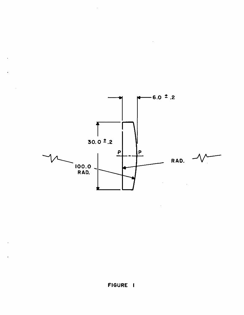
The final design of the field lens is shown in Figure 1. It is a plano-
convex lens made of UBK-7 glass, 30mm in diameter, 6.0mm thick, and with a
radius of curvature of 100.0mm.
B. Relay System
As was mentioned in Section II, it was felt that an apochromatic lens
would be required. However, in order to test this hypothesis, a design was
made of a normal achromat, using good common glasses, with chromatic correction
made at the F(blue hydrogen line, 0.4861ym) and the C(red hydrogen line,
0.6563ym) points of the spectrum. Figure 2 shows the real focus curve for
this achromat; note that the defocusing at the extremes of the desired
spectrum is intolerable. It was, therefore, confirmed that an apochromat
would be required.
-6-

FIGURE 1
- FIELD LENS -
1. Dimensions are in mm.
2. Surfaces marked "P" are polished, all
others ground.
3. Chamfer all edges .5 x 45 .
4. Centered to .05 edge run out.
5. Coating to be UV HEA registered or
equivalent.
6. Material: UBK-7 glass (Schott #517643).
7. Specification per drawing #01085 to
apply.
100.0 ^RAD.
RAD.
FIGURE I

100.0 ^RAO.
6.0 = .2
RAD.
FIGURE I

24 -•
20 -•
16 -•
2°= 124
ao
8 -
4 - •
0 -•
0.3 0.5 0.7 0.9 I.I
WAVELENGTH(Microns)
FIGURE 2

It is theoretically possible to design an apochromat using ordinary
optical glasses; however, such a design would probably require seven or
eight different elements and would be very expensive to manufacture and
difficult to assemble and align. It was, therefore, decided to investigate
the use of a flourite apochromat. Figure 3 shows the improvement possible
with a flourite apochromat. In terms of the resolution requirements, the
flourite lens would allow one to focus on a bright image, then photograph
in any selected wavelength without refocusing.
Figures 2 and 3 are for air spaced triplets similar to the configuration
of Figure 4. However, a triplet is sensitive to manufacturing errors and
would have two flourite elements as the outside elements, subject to damage.
A pair of cemented doublets, as shown in Figure 5, was finally selected as
the "optimum" solution to the problem. Each doublet is identical, resulting
in savings during fabrication and greater dependability of assembly. By
their nature, since the bulk of correction is carried at the cemented inter-
face, doublets are less sensitive to misalignment during assembly. Should
the lenses ever become loose in their cells, or the cells slightly bent,
the optical correction would not be greatly affected. An air spaced triplet,
on the other hand, is susceptable to failure under abusive conditions.
An additional advantage of using cemented doublets is that surface
reflections are minimized. This is especially useful when using flourite,
since it tends to scatter no matter how carefully polished. Ghosts are
unlikely to arise in the cemented doublet relay system since all air-glass
surfaces are convex. Also, the flourite lenses are the internal elements,
protected from damage. Figure 6 shows the final configuration of the twin
doublets.
The final design was aided by a computer program, ACCOS/GOALS Version
-9-

12 -•
8 -•
4 -•
o «
0 -•
35O
-6 -•
0.3 0.5 0.7 0.9
1.0
1 1 1 hI.I
WAVELENGTH(Microns)
FIGURE 3

FIGURE 4
AIR SPACED TRIPLET APOCHROMATIC LENS SYSTEM
FIGURE 5
EQUIVALENT APOCHROMATIC LENS SYSTEM,
UTILIZING TWIN AIR SPACED DOUBLETS

FLOURITE
FLINT GLASS
FIGURE 4
FLINT GLASS
FLOURITE
FIGURE 5

FIGURE 6
DOUBLET LENS (One half of Apochromat)
1. Dimensions are in mm.
2. Surfaces marked "P" are polished, all others
ground.
3. Chamfer all edges .5 x 45°.
4. Centered to 0.20 edge run out prior to
cementing.
5. Specification #01085 shall apply to each
lens element.

MATERIAL'BAUSCH 8 LOMB6I3442D GRADE APER MIL-G-174
724,44RAD.
MATERIAL^HARSHAW CHEMICAL CORP.OPTICAL GRADE CALCIUMFLOURIDE OR EQUIV.
T28.0DIA.
+0.2-0
69.183RAD.
44.875RAD.
FIGURE 6

IV, originally devised by Scientific Calculations, Inc., of Rochester, New
York. Field curvature was found to be the limiting problem. As a design
philosophy, spherical aberration was intentionally undercorrected in order
to balance the field curvature over the field of view. With this approach,
some axial resolution was sacrificed in order to obtain a "flat" field.
Figure 7 shows the focal curve-vs-wavelength (longitudinal chromatic
aberration) for the selected design. It shows that the paraxial color is
well corrected. Computer calculation of aberration coefficients at five
different wavelengths, from 0.4341 to 0.7682ym, shows that correction is
well behaved over at least this range; slight refocussing, best determined
by experimentation, may be desirable in order to obtain highest resolution
at the short and long wavelength extremes.
Figures 8 and 9 show the radial energy distribution (R.E.D.) of the
entire system including the 90-inch telescope. The field (maximum) is
25.4mm in diameter. The R.E.D. is perhaps the best means of determining
point-resolution, since mean transfer function (MTF) is strictly useful
only for continuous objects. Thus, stating that this system will resolve
20 lines/mm is somewhat misleading; 20 lines/mm means bars which have an
angular spacing of 0.5 arc-sec in this arrangement. But, resolving an
array of black-and-white bars is not the same as resolving points of light
separated by 0.5 seconds. This design guarantees the latter.
Figures 10, 11, 12, and 13 are spot diagrams of ray traces performed
by the computer for on-axis and three field points, at the "best focus".
The circles on these diagrams represent a point O.lmm in diameter. Note
that in focusing the instrument, it is necessary to not focus on axis,
but at 0.7 of the 25.4mm diameter field. This gives the best "mean" focus
over the entire field. If desired, resolution on axis can be increased
-13-

0.5--
Oo:QC~.u g-I E< —'uou.
0 --
-0.5 - •
0.4 0.5 0.6 0.7
WAVELENGTH(Microns)
0.8 0.9 1.0
FIGURE 7

ioo 4
otrUJz *-UJ £
oo 2uj «co Q-O ^_iozUJ
20 4
20 40 60 80 100
SPOT RADIUS(Microns)
FIGURE 8

ioo 4
UJ
100
SPOT RADIUS(Percent)
FIGURE 9
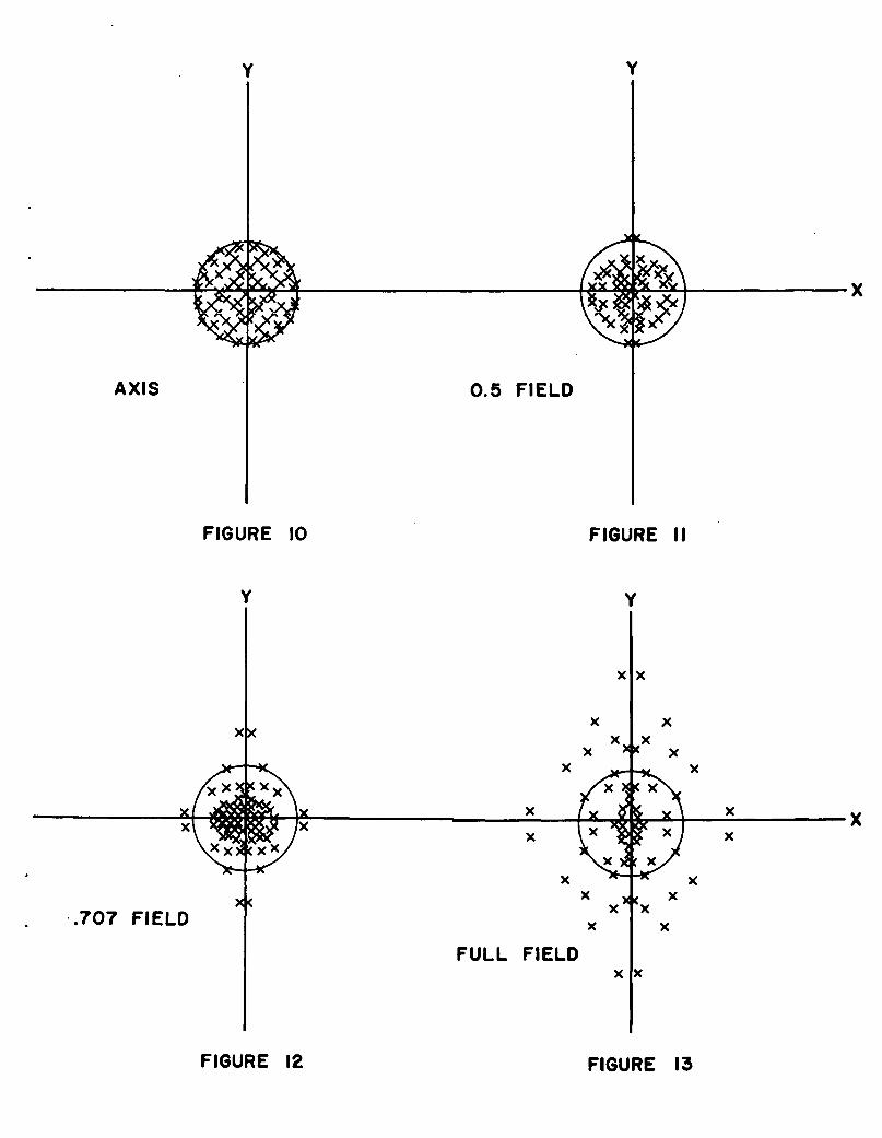
AXIS 0.5 FIELD
FIGURE 10
.707 FIELD. x c
FULL FIELD
FIGURE 12 FIGURE 13

slightly by focusing on axis and sacrificing the edges of the field.
C. Housing
The cemented doublets are contained in a housing as shown in Figure
14. The mounting brackets for attaching the housing to the guidance actuators
are not shown. The field lens is mounted in a separate housing (not guided)
approximately 157mm in front of the relay lens.
IV. PERFORMANCE
The relay system was manufactured by the Herron Optical Company and has
been tested and installed in the IDCADS. The system meets all of the per-
formance specifications of Section I-B. The relay lens (Figure 14) is 28mm
in diameter by 44.5mm in length and weighs 115 grams.
As intended in the design approach in order to obtain the necessary
field flatness, the lens has considerable negative spherical aberration.
However, the required resolution (0.5 arc-seconds) is met over the entire
25.4mm field without changing the focus if the system is adjusted for
sharpest focus at a point approximately 9mm from the center of the field.
No refocusing is required for a spectral range from 4000A to lym; slight
refocusing is required for sharp focus when operating in the region from
3700A to 4000A.
APPENDIX
The following specifications are for lens elements 01081, 01082, and
01084.
1. Radius accuracy: all radii shall be accurate to 5 rings.
2. Regularity: all surfaces shall be regular to 1 fringe (half
wave) .
3. Scratch: no scratches in excess of .Olmm width. Cumulative
length of scratches between .005mm and .Olmm shall be less than
-18-

FIGURE 14
RELAY LENS ASSEMBLY--
1. Dimensions are in mm
2. Housing Material: 6061-T6 Aluminum
3. Finish Aluminum Parts: Black
Anodize per MIL A-8625 Type 2
4. The 6.96mm Spacer may be modified
during final testing
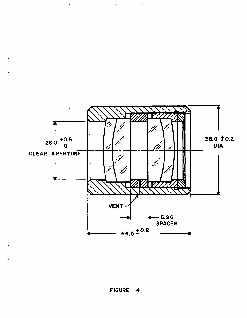
26-° -oCLEAR APERTURE
38.0 ±0.2OIA.
FIGURE 14
50mm. Finer scratches may be tolerated to the extent they do
not constitute an unpolished condition.
4. Bubbles and digs: no digs or bubbles greater than ,06mm. No
more than two per element between .03 and ,06mm. Finer digs
and bubbles acceptable so long as they do not constitute an
unpolished condition.
5. Stain: blue stains or heavy brown stains are cause for rejection.
Medium brown stain is acceptable.
6. Chips and blisters: acceptable so long as they fall outside of
the clear apertures.
7. Glass elements to have ordinary kiln annealing. Strain: retardation
less than 10 millimicrons per cm.
8. Coating: all glass surfaces to be coated UV HEA registered or
equivalent.
-20-