the underfloor heating company - amazing prices & free
TRANSCRIPT


65 Time Clock Series Model: TM1 / TM1-N
1. Day Indicator - Displays the current day.
2. Holiday Indicator - Displayed when the programmer is in holiday mode.
3. Program Cycle Indicator - Displayed during programming only to show which
period is being altered.
4. Keypad Lock Indicator - Displayed when the keypad is locked.
5. Timer Status - Displays the current status of the timed output.
6. Clock - Digital clock display in 24h format.
LCD Display1
2 3 4
6
5


109 Time Clock Series Model: TM1 / TM1-N
Communication Setting (TM1-N Only)
To set the communications number, follow these steps.
• Press and hold the Power button to turn the time clock OFF .............................
• Press and hold the Clock button until the display appears .................................
• The display will appear as shown below showing feature number 01
• Use the Up/Down buttons to set a unique communication address .....
• Press A to confirm settings ..............................................................................................
• Press the Power button once to turn the time clock back ON ............................
Communication Address
(01-32)
Feature
Setting the Clock
To set the clock, follow these steps.
• In Countdown mode, press the Clock button once .................................................
• In either 5/2 or 7 Day mode, press the Clock button twice ....................................
• Use the Up/Down buttons to set the hours ......................................................
• Press H to confirm settings ...............................................................................................
• Use the Up/Down buttons to set the minutes .................................................
• Press H to confirm settings ...............................................................................................
• Use the Up/Down buttons to set the day of the week ..................................
• Press A to confirm settings and return to the main display ..................................
Day
Hours
Minutes

1413 Time Clock Series Model: TM1 / TM1-N
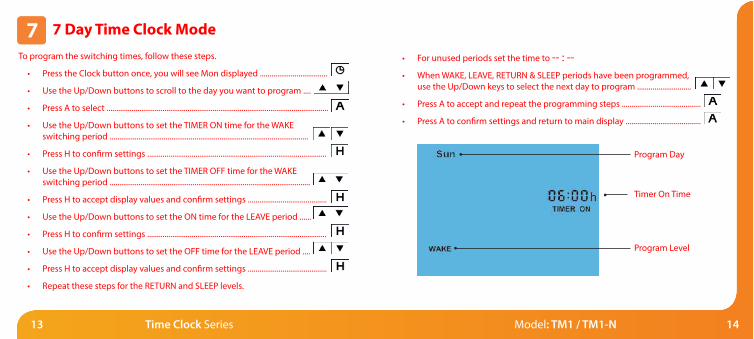
7 Day Time Clock Mode
To program the switching times, follow these steps.
• Press the Clock button once, you will see Mon displayed ...................................
• Use the Up/Down buttons to scroll to the day you want to program ....
• Press A to select ...................................................................................................................
• Use the Up/Down buttons to set the TIMER ON time for the WAKE
switching period .......................................................................................................
• Press H to confirm settings .............................................................................................
• Use the Up/Down buttons to set the TIMER OFF time for the WAKE
switching period ........................................................................................................
• Press H to accept display values and confirm settings .........................................
• Use the Up/Down buttons to set the ON time for the LEAVE period ......
• Press H to confirm settings .............................................................................................
• Use the Up/Down buttons to set the OFF time for the LEAVE period ....
• Press H to accept display values and confirm settings .........................................
• Repeat these steps for the RETURN and SLEEP levels.
• For unused periods set the time to -- : --
• When WAKE, LEAVE, RETURN & SLEEP periods have been programmed,
use the Up/Down keys to select the next day to program ............................
• Press A to accept and repeat the programming steps .........................................
• Press A to confirm settings and return to main display .......................................
Program Level
Program Day
Timer On Time

1615 Time Clock Series Model: TM1 / TM1-N
Timer Override
The time clock is able to override its current timer status.
If the TM1 is in the Timer ON mode – pressing A will switch it to Timer OFF .....
(TIMER OFF will flash to inform you the programmed output has been overridden)
The TM1 will return to the program at the next programmed time.
Countdown Mode
• Use the Up/Down buttons to set the countdown duration ...............
• Press A to confirm settings ......................................................................................
• Hold For will appear showing the time left.
When Hold For is displayed on screen, the output will be active.
To cancel a countdown period, reduce time to 00:00.
Timer Status
Hold For Icon
Hold Time Remaining
Timer Status
(Flashes in Override)
Time

1817 Time Clock Series Model: TM1 / TM1-N
Holiday
The holiday function allows you to quickly enter a holiday setting.
During a holiday, the time clock will maintain TIMER OFF.
At the end of your holiday, the time clock will revert back to the programmed setting.
• Press H once (you will see the suitcase displayed on screen) ............................
• Use the Up/Down buttons to enter the number of days holiday ............
• Press A to confirm settings .............................................................................................
The display will show a suitcase indicating the time clock is in holiday mode.
To cancel, follow the same steps but reduce the Holiday duration to 00 days.
Holiday Days
Holiday ON Indicator
Factory Reset
To perform a factory reset, follow these steps.
• Press and hold the Power button to turn the thermostat OFF .........................
• Press and hold the Power and Up buttons together until the
LCD powers up. All of the icons will be displayed on screen ..........................
• When the icons have disappeared from the screen, the thermostat has
been successfully reset.
• Press the Power button once to turn the time clock back ON ...........................
The time clock has a reset function to restore all settings to their factory defaults.
All icons displayed simultaneously. Factory reset is complete.Note: A holiday period
does not start until 00:00
the next day. For example,
if you set a holiday period
on Friday for 2 days,
Saturday will be counted
as the first day and the
time clock will revert
back to the programmed
schedule at 00:00 on
Monday.

2019 Time Clock Series Model: TM1 / TM1-N
Wiring Diagram - TM1 Switched Live Output Wiring Diagram - TM1 Switched Output Voltfree
MAINS SUPPLY
230V SWITCHED LIVEOUTPUT - 3 AMPS
FROM FUSED SPUR
Model: TM1
A1A2 LN
230VAC
MAINS SUPPLY
SWITCHED OUTPUTVOLTFREE RATED230V AC - 3 AMPS
FROM FUSED SPUR
Model: TM1
A1A2 LN
230VAC

2221 Time Clock Series Model: TM1 / TM1-N
Notes
The time clock can be used to control various electrical devices in and around your
home e.g. lighting, electric towel rails, hot tubs, sauna’s etc.
Refer to the manufacturers instructions for wiring to these devices.
Common time clock wiring requirements are shown in the diagrams on pages 19-21.
.........................................................................................................................................................................
.........................................................................................................................................................................
.........................................................................................................................................................................
.........................................................................................................................................................................
.........................................................................................................................................................................
.........................................................................................................................................................................
.........................................................................................................................................................................
.........................................................................................................................................................................
.........................................................................................................................................................................
.........................................................................................................................................................................
Wiring Diagram - TM1-N to UH1
UH1
ZONE X
A2
A1
B
Y
_
+
ZONE X
A2
A1
B
Y
_
+
Model: TM1-N
- A2 A1 +Y B
12VDC