the true microstructure of materials
TRANSCRIPT

7/28/2019 The True Microstructure of Materials
http://slidepdf.com/reader/full/the-true-microstructure-of-materials 1/9
5
Abstract
The microstructure expresses a high num-
ber of properties of a material. For this
reason materialographic - or if we use the
older, more common terminology, metallo-
graphic - preparation is important for both
production - and research work.
In 1863 H. C. Sorby prepared the first
“true structure” of steel, but for many years
the importance of the preparation process
was neglected, resulting in structures with
many artifacts. In the 1930s the AmericanJ.R. Vilella takes up the preparation of a
“true structure” and in the 1950s to 70s
the Australian L.E. Samuels describes in a
conclusive way, how to obtain a true struc-
ture by mechanical methods.
In mechanical preparation, the removal
rate and deformation are decisive factors
for obtaining a true structure or one with a
minimum of artifacts.
Prior to World War 2 hand preparation with
Al2O
3(emery paper and alumina) was used.
In the 1950s semi-automatic machines
with rotating discs were developed, using
SiC and diamond as grinding/polishing
media.
Preparation artifacts in the structure might
create an “untrue” structure which can
mistakenly be accepted as “true”. A num-
ber of examples are given.
Materialography/Metallography
For the title of this article I have used the
word MATERIALOGRAPHY, instead of the
usual METALLOGRAPHY. Considering thatwe work with not only metals, but ceram-
ics, plastics, electronic parts etc, MATE-
RIALOGRAPHY could be a more correct
name. As early as 1968 Crowther and
Spanholtz wrote an article in Metal Progress
called “A new name for Metallography? Try
Materialography” (1).
Materialography covers a very wide field in
material investigation. Materialography
bridges the gap between science and
engineering (Fig.1) (2).
The microstructural parameters strongly
influence many of the properties of a
material (Fig.2)(2). Each material contains
The True Microstructure
of MaterialsMaterialographic Preparation from Sorby to the Present
Kay Geels, Struers A/S, Copenhagen, Denmark
many millions of microstructural features
per cubic centimetre. These microstruc-
tural features can exist in sizes spanning
more than ten orders of magnitude (Fig. 1).
Today there is a whole range of instru-
ments with which nearly all of the features
across this range can be made visible. In
this sense the expression Continuous
Metallography or rather Continuous
Materialography , has been coined (3),
covering examination from the macro to
the atomic level.
The microstructure we see in the micro-
scope is two dimensional, but we should
not lose sight of the fact that the constitu-
ents in a material are three dimensionally
arranged.
A photo montage shows the prepared
surface with the microstructure and the
material below the surface (Fig.3)(2). It can
be seen that the true size of the grains
cannot be deduced from the microstruc-
ture. A statistic extrapolation of a micro-
structure with elongated grains shows that
based on the two dimensional surface,
approx. 80% of the grains are relatively
short and have an almost equiaxial shape.
An extrapolation of the grain population in
three dimensions, however, reveals a much
higher variation in grain length and the
average grain length is longer.
Having realized the limitations of the two-
dimensional structure, we can establish
the fact that the examination of the micro-
structure is of enormous importance. From
now on I shall concentrate on the quality of
this structure.
Fig. 1
Fig. 2

7/28/2019 The True Microstructure of Materials
http://slidepdf.com/reader/full/the-true-microstructure-of-materials 2/9
6
The True Structure
Historical. Before we go into a more
exact definition of the true structure, we
shall look at one of the first true structures
pro-duced. In 1863-65 H.C. Sorby made a
number of preparations of steel; an exam-
ple is a structure of Bessemer steel con-
taining ferrite and pearlite (Fig.4)(4). We
know today that this structure is correct, a
true structure without artifacts. H.C. Sorby
was fully aware that to obtain a true struc-
ture, the surface must be treated very
carefully.
After Sorby it seems that nobody really
paid attention to the preparation of the true
structure for many years.
The American J.R. Vilella in the 1930s
seems to be the first to establish a defini-
tion of the true structure and point out the
importance of a correct preparation, avoid-
ing surfaces with distorted metal (6).
He showed how a structure at that time,
known as “sorbite” or “troostito - sorbite”
is normal pearlite severely distorted during
polishing (Figs.5 and 6).
Based on the work by Vilella, the Austral-
ian L.E. Samuels since the 1950s estab-
lished the conclusive work on metallo-
graphic preparation by mechanical meth-
ods. He pointed out the importance of the
preparation process to obtain a true struc-
ture. Without this the best examinations
and inspired interpretations of the structure
will be of no avail (5).
Definition of the True Structure. Basedon Vilella and Samuels the true structure
can be defined: (7)
No deformation
No scratches
No pull-outs
No false structures (artifacts)
No introduction of foreign elements
No smearing
No relief or rounded edges
No thermal damage
The preparation process will always influ-
ence the prepared surface. This influence
is concentrated in certain parts of the sur-
face, “danger zones”, where the risk of
artifacts is higher (Figs. 8 and 9).
With mechanical polishing an approximate
true structure can be obtained when the
correct procedures are followed, even with
very heterogeneous materials, whereas
electrolysis may create problems if more
than one phase is present in the structure
during electrolytic polishing.
Considering that most materials are hete-
rogeneous (or non-conductive), mechani-
cal polishing is by far the most used
method, and this will be the only one dis-
cussed in the following text.
Mechanical Preparation
Two features should be considered during
mechanical preparation:
Removal rate. The rate at which material
is removed from the surface of the spe-
cimen.
Deformation. The nature and depth of the
plastically deformed layer that is produced
in the specimen surface.
In general we want the removal rate to be
as high as possible and the deformation to
be as low as possible. This depends on
the interaction between the abrasive grain
and the specimen surface.
Removal Rate - Grinding. Grinding is the
first stage in the preparation process.
When preparing a specimen both cutting
and grinding involve abrasives, either fixed
in a bond as on a cut-off wheel or fixed to
a coated surface like grinding pa-per. In
the case of composite discs, the abrasive
grains are added to the surface in a freeflow, but we shall see later that even in this
case, the grain - when cutting action takes
place - is fixed. Silicon carbide (SiC),
aluminium oxide (Al2O
3 ) and diamond are
mainly used as abrasives.
Influence of Grinding Process on Removal
Rate. Three modes of interaction can be
recognized (5):
Lapping::::: The grain rolls between the
specimen and the preparation disc (Fig.9).
A corner of the grain digs into the speci-
men and turns, leaving a small cavity with
strong deformation. The removal rate is
Fig. 3. Photo-montage of a micro section of
silicon nitride alloy superimposed upon a pile of
silicon nitride crystallite
Fig. 4. Original Sorby specimen 1863,
Bessemer steel 0.2% carbon. BF, 450:1
Fig. 5. “troostito-sorbite”. BF, 1000:1
Fig. 6. Same as Fig. 5, normal pearlite. BF,
1000:1

7/28/2019 The True Microstructure of Materials
http://slidepdf.com/reader/full/the-true-microstructure-of-materials 3/9
7
35
very low and lapping is not suited for metal-
lographic preparation.
Grinding: The grain is fixed and acts as a
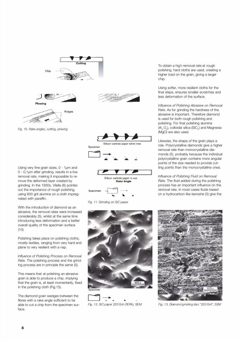
machine tool, because the rake angle is
correct for cutting a chip (Fig.10). The rake
angle can be positive, 0 or negative, and
grinding only takes place when the angle is
positive, 0 or to a certain degree negative.
At a given negative angle, the critical rake
angle, the chip is not made anymore and
the grain starts “plowing” instead of cutt-
ing. When grinding, the efficiency of material removal approaches 100%.
Plowing: When plowing, the rake angle is
so negative that only a groove is made in
the specimen surface (Fig. 10). A standing
wave bulge forms in front of the grain, and
material is displaced into a ridge, on each
side of the groove. The removal rate
approaches zero.
As well as the rake angle, the geometric
shape of the grain is also important (5).
The most effective shape is a V-form, crea-
ting an efficient chip, provided that the
rake angle is correct. If the grain is flat, the
cross-section of the chip is reduced and in
the case of flat grains of a certain size, the
specific pressure between grain and sur-
face will decrease and no cutting will take
place, resulting in plowing or no action at all.
Grinding surfaces. We have so far identi-
fied two important parameters, rake angle
and grain shape.
We can now relate these to the two grind-
ing surfaces, waterproof SiC paper, which
is commonly used and a surface with dia-mond grains.
At 220 gri t SiC paper we see the different
angles and shapes and it is evident that
also the grain size varies widely (Figs.11
and 12)(5)(8). At 220 grit, the average grain
size is 59 µm and the largest allowed grain
size is 74 µm. Because of this large varia-
tion in rake angles, shape and size, only 1
or 2% of the many visible grains of the
grinding paper, actually remove material by
cutting a chip. About the same proportion
produce scratches in the surface by
plowing. The remainder have no effect (5).
During the process the SiC grains are bro-
ken down and after a period of time most
grains will be relatively flat from fracturing
and wear so that cutting a chip will change
into plowing.
Using a diamond grinding disc as the
grinding surface, with the diamonds partly
embedded in a bond, the process is
somewhat different from the grinding pa-
per (Fig.13). The fracturing is lower, partly
because the diamond grains are not as
brittle as the SiC and partly because the
grain is fixed in the bond. It appears thatthe diamond grains composed with facets,
constitute effective cutting points (5), which
give a higher removal rate. The diamond
grinding disc normally has a constant re-
moval rate over a long period of time, as
long as the surface is not clogged by
ground-off material. This is avoided with an
efficient flow of grinding fluid and a con-
figuration of the surface so that the debris
is channelled away from the grinding sur-
face.
Composite discs (platens) are mostly used
for the fine steps in grinding. The surface
consists of a resin reinforced with a metal
powder, and the abrasive, mostly diamond
is added during the process.
It is very important that the surface is able
to fix the abrasive grain, establishing a
grinding process (Fig.14). If a large portion
of the grains are rolling between the disc
surface and the specimen surface, a lap-
ping action is established causing a very
low removal rate and heavy deformation.
Heating of the specimen surface mightcause artifacts and if debris is not re-
moved, the clogged grinding surface will
cause severe damage to the specimen
surface.
Removal Rate - Polishing. Polishing is
the last stage in mechanical preparation. It
is very important for two reasons, the
deformation from grinding must be
removed (rough polishing), and the surface
established after the last polishing step
(final polishing), should preferably repre-
sent the “true structure”. Alumina (Al2O
3 ) in
different grain sizes and crystal structures
were - for many years - the most used
abrasive for polishing.
Fig. 7. Mechanical polishing. “Danger zones”
Fig. 8. Electrolytic polishing. “Danger zones”
Fig. 9. Lapping
The True Microstructure of Materials
7/28/2019 The True Microstructure of Materials
http://slidepdf.com/reader/full/the-true-microstructure-of-materials 4/9
8
Using very fine grain sizes, 0 - 1µm and
0 - 0,1µm after grinding, results in a low
removal rate, making it impossible to re-
move the deformed layer created by
grinding. In the 1930s, Vilella (6) pointed
out the importance of rough polishing,
using 600 grit alumina on a cloth impreg-
nated with paraffin.
With the introduction of diamond as an
abrasive, the removal rates were increased
considerably (5), whilst at the same time
introducing less deformation and a better
overall quality of the specimen surface
(10).
Polishing takes place on polishing cloths,mostly textiles, ranging from very hard and
plane to very resilient with a nap.
Influence of Polishing Process on Removal
Rate. The polishing process and the grind-
ing process are in principle the same (5).
This means that at polishing an abrasive
grain is able to produce a chip, implying
that the grain is, at least momentarily, fixed
in the polishing cloth (Fig.15).
The diamond grain wedges between the
fibres with a rake angle sufficient to be
able to cut a chip from the specimen sur-
face.
To obtain a high removal rate at rough
polishing, hard cloths are used, creating a
higher load on the grain, giving a larger
chip.
Using softer, more resilient cloths for the
final steps, ensures smaller scratches and
less deformation of the surface.
Influence of Polishing Abrasive on Removal
Rate. As for grinding the hardness of the
abrasive is important. Therefore diamond
is used for both rough polishing andpolishing. For final polishing alumina
(Al2O
3 ), colloidal silica (SiO
2 ) and Magnesia
(MgO) are also used.
Likewise, the shape of the grain plays a
role. Polycrystalline diamonds give a higher
removal rate than monocrystalline dia-
monds (5), probably because the individual
polycrystalline grain contains more angular
points of the size needed to provide cut-
ting points than the monocrystalline ones.
Influence of Polishing Fluid on Removal
Rate. The fluid added during the polishing
process has an important influence on the
removal rate. In most cases fluids based
on a hydrocarbon like kerosine (5) give the
Fig. 10. Rake angles, cutting, plowing
Fig. 11. Grinding on SiC paper
Fig. 12. SiC paper 220 Gri t (FEPA), SEM Fig. 13. Diamond grinding disc “220 Gri t”, SEM

7/28/2019 The True Microstructure of Materials
http://slidepdf.com/reader/full/the-true-microstructure-of-materials 5/9
9
35
highest removal rate. A similar effect can
be obtained using an alcohol based fluid.
Fluids are also important for surface
cooling.
Deformation - Grinding. The separation
of a chip during machining operations
induces complex systems of plastic
deformation in both the separating chip
and the specimen material. An inevitable
consequence is that a layer plastically
deformed during machining, is left in the
new surface that is produced. In generalterms, the strains in this layer are very
large at the surface and decrease more or
less exponentially with depth.
This deformed layer becomes important in
metallography, when the plastic deforma-
tion changes the microstructure of the
specimen in a way that can be detected in
the particular microscopic examination that
is to be carried out. The layer is then an
important potential source of false
structures, or preparation artifacts, the
avoidance of which is one of the primary
objectives of a materialograhic preparation
sequence (5).
Influence of Grinding Process on Deforma-
tion. During grinding the abrasive grains
act as machine tools set at different rake
angles. When a chip is separated from the
surface, the shear strains are concentrated
in the so-called shear zone in front of the
tool. A region adjacent to this shear zone,
and extending into the specimen in ad-
vance of the tool is also plastically defor-
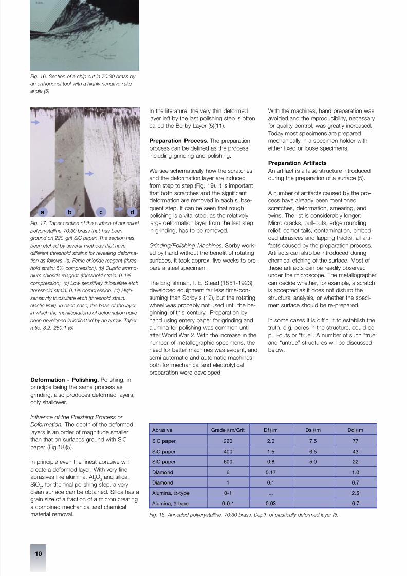
med, though to a lesser degree (Fig. 16).
Samuels (5) has done an exhaustive study
of the deformation created in the specimen
surface, by using taper sections. A taper
section is produced by preparing the spe-
cimen at a small angle, the taper angle.
When using a taper angle of 5°44' a 10 x
enlargement it obtained, making it possible
to analyse a greater surface structure detail
under an optical microscope (9).
A taper section of 70:30 brass ground on
a 220 grit SiC paper, shows the surface of
the specimen with scratches and the
deformation below (Fig.17).
Samuels (5) split up the layers into three
levels of deformation:
Depth of fragmented layer (Df)
Approximately equal to the depth of the
surface scratches.
Depth of deformation (Dd)
Maximum depth beneath the root of the
surface scratches to the elastic-plastic
boundary (Fig 18 (d)).
Depth of significant deformation (Ds)
Maximum depth beneath the root of the
surface scratches of the deformation that
will noticeably affect the observations to be
made on the finished surface.
Example: Annealed polycrystalline 70:30
Brass, SiC grinding paper, 220 grit, with
water
Df (scratches): 2 µm
Dd: 77 µm
Ds: 7.5 µm
The fragmented layer consists of severe
plastic deformation and is easily recog-nized. In the deformed layer, the material
can be modified in different ways, such as
strain induced transformation (austenitic
steel) or massive twinning (polycrystalline
zinc).
Fig. 14. Grinding on a composite disc
Fig. 15. Abrasive grain fixed in polishing cloth
The True Microstructure of Materials
Chip Abrasive
particle
Fibre of
polishing
cloth
7/28/2019 The True Microstructure of Materials
http://slidepdf.com/reader/full/the-true-microstructure-of-materials 6/9
10
dddddbbbbb cccccaaaaa
Deformation - Polishing. Polishing, in
principle being the same process as
grinding, also produces deformed layers,
only shallower.
Influence of the Polishing Process on
Deformation. The depth of the deformed
layers is an order of magnitude smaller
than that on surfaces ground with SiC
paper (Fig.18)(5).
In principle even the finest abrasive will
create a deformed layer. With very fine
abrasives like alumina, Al2O
3and silica,
SiO2, for the final polishing step, a very
clean surface can be obtained. Silica has a
grain size of a fraction of a micron creating
a combined mechanical and chemical
material removal.
In the literature, the very thin deformed
layer left by the last polishing step is often
called the Beilby Layer (5)(11).
Preparation Process. The preparation
process can be defined as the process
including grinding and polishing.
We see schematically how the scratches
and the deformation layer are induced
from step to step (Fig. 19). It is important
that both scratches and the significant
deformation are removed in each subse-quent step. It can be seen that rough
polishing is a vital step, as the relatively
large deformation layer from the last step
in grinding, has to be removed.
Grinding/Polishing Machines. Sorby work-
ed by hand without the benefit of rotating
surfaces, it took approx. five weeks to pre-
pare a steel specimen.
The Englishman, I. E. Stead (1851-1923),
developed equipment far less time-con-
suming than Sorby’s (12), but the rotating
wheel was probably not used until the be-
ginning of this century. Preparation by
hand using emery paper for grinding and
alumina for polishing was common until
after World War 2. With the increase in the
number of metallographic specimens, the
need for better machines was evident, and
semi automatic and automatic machines
both for mechanical and electrolytical
preparation were developed.
With the machines, hand preparation was
avoided and the reproducibility, necessary
for quality control, was greatly increased.
Today most specimens are prepared
mechanically in a specimen holder with
either fixed or loose specimens.
Preparation Artifacts
An artifact is a false structure introduced
during the preparation of a surface (5).
A number of ar tifacts caused by the pro-
cess have already been mentioned;scratches, deformation, smearing, and
twins. The list is considerably longer:
Micro cracks, pull-outs, edge rounding,
relief, comet tails, contamination, embed-
ded abrasives and lapping tracks, all arti-
facts caused by the preparation process.
Artifacts can also be introduced during
chemical etching of the surface. Most of
these artifacts can be readily observed
under the microscope. The metallographer
can decide whether, for example, a scratch
is accepted as it does not disturb the
structural analysis, or whether the speci-
men surface should be re-prepared.
In some cases it is difficult to establish the
truth, e.g. pores in the structure, could be
pull-outs or “true”. A number of such “true”
and “untrue” structures will be discussed
below.
Fig. 16. Section of a chip cut in 70:30 brass by
an orthogonal tool with a highly negative rake
angle (5)
Fig. 17. Taper section of the surface of annealed
polycrystalline 70:30 brass that has been
ground on 220 grit SiC paper. The section has
been etched by several methods that have
different threshold strains for revealing deforma-
tion as follows. (a) Ferric chloride reagent (thres-
hold strain: 5% compression). (b) Cupric ammo-
nium chloride reagent (threshold strain: 0.1%
compression). (c) Low sensitivity thiosulfate etch
(threshold strain: 0.1% compression. (d) High-
sensitivity thiosulfate etch (threshold strain:
elastic limit). In each case, the base of the layer
in which the manifestations of deformation have
been developed is indicated by an arrow. Taper
ratio, 8.2. 250:1 (5)
Fig. 18. Annealed polycrystalline. 70:30 brass. Depth of plastically deformed layer (5)
Abrasive Grade m m/Grit Df m m Ds m m Dd m m
SiC paper 220 2.0 7.5 77
SiC paper 400 1.5 6.5 43
SiC paper 600 0.8 5.0 22
Diamond 6 0.17 1.0
Diamond 1 0.1 0.7
Alumina, a -type 0-1 ... 2.5
Alumina,g
-type 0-0.1 0.03 0.7
7/28/2019 The True Microstructure of Materials
http://slidepdf.com/reader/full/the-true-microstructure-of-materials 7/9
11
35
Reproducibility
Reproducibility is of utmost importance
both in research and production.
Using e.g. image analysis is of no use, if
the preparation process is not able to pro-
duce reproducible results. An example of
quality control of a material is pores in a
plasma spray coating. Relatively small
variations in the process or in the consum-
ables will cause a variation in the number
of pores to be seen under the microscope.
“True” and “Untrue” Structures
In the following an “untrue” structure is de-
fined as a structure, which in principle could
be correct; only the experienced metallo-
grapher is able to see that the structure
might have one or several artifacts.
Plasma spray coatings. Materialographic
examination is very important to establish
the quality of a plasma spray coating. A
number of parameters can be examined:
porosity, cracks, amount of oxide, interface
contamination, unmelted particles and
microhardness.
With plasma coatings it is very important
to obtain a true structure, as the coatings
are often used for high technological appli-
cations, like turbine blades for jet engines.
This means that the quality requirements
must be met whilst at the same time
avoiding waste of valuable components.
With plasma spray coatings we often see
two artifacts, smearing and pull-outs.
Material: 88/12 WC/Co (13). This coating
is very hard due to the WC particles, but
the Co matrix is relatively ductile. It means
that when using finer SiC grinding papers,
the WC particles are moved into the pores
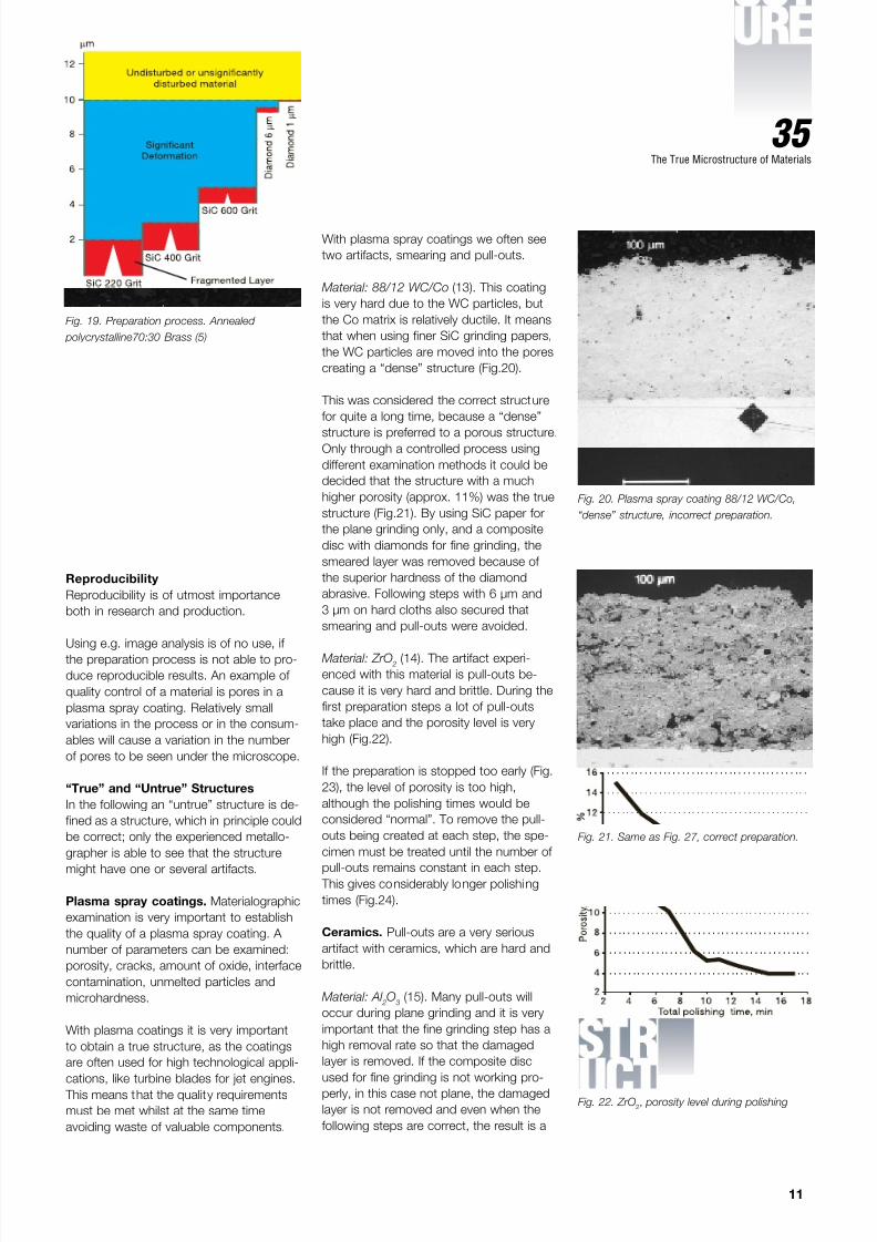
creating a “dense” structure (Fig.20).
This was considered the correct structure
for quite a long time, because a “dense”
structure is preferred to a porous structure.Only through a controlled process using
different examination methods it could be
decided that the structure with a much
higher porosity (approx. 11%) was the true
structure (Fig.21). By using SiC paper for
the plane grinding only, and a composite
disc with diamonds for fine grinding, the
smeared layer was removed because of
the superior hardness of the diamond
abrasive. Following steps with 6 µm and
3 µm on hard cloths also secured that
smearing and pull-outs were avoided.
Material: ZrO 2
(14). The artifact experi-
enced with this material is pull-outs be-
cause it is very hard and brittle. During the
first preparation steps a lot of pull-outs
take place and the porosity level is very
high (Fig.22).
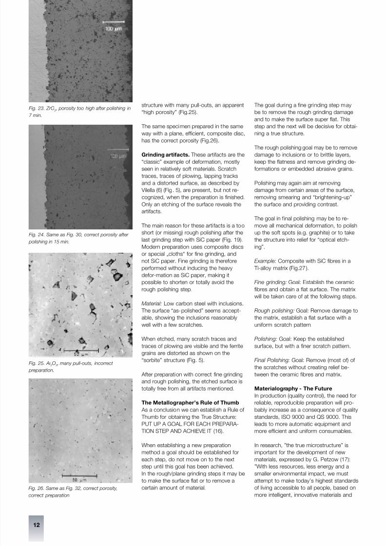
If the preparation is stopped too early (Fig.
23), the level of porosity is too high,
although the polishing times would be
considered “normal”. To remove the pull-
outs being created at each step, the spe-
cimen must be treated until the number of
pull-outs remains constant in each step. This gives considerably longer polishing
times (Fig.24).
Ceramics. Pull-outs are a very serious
artifact with ceramics, which are hard and
brittle.
Material: Al 2O
3(15). Many pull-outs will
occur during plane grinding and it is very
important that the fine grinding step has a
high removal rate so that the damaged
layer is removed. If the composite disc
used for fine grinding is not working pro-
perly, in this case not plane, the damaged
layer is not removed and even when the
following steps are correct, the result is a
Fig. 19. Preparation process. Annealed
polycrystalline70:30 Brass (5)
Fig. 20. Plasma spray coating 88/12 WC/Co,
“dense” structure, incorrect preparation.
Fig. 21. Same as Fig. 27, correct preparation.
The True Microstructure of Materials
Fig. 22. ZrO2, porosity level during polishing
7/28/2019 The True Microstructure of Materials
http://slidepdf.com/reader/full/the-true-microstructure-of-materials 8/9

7/28/2019 The True Microstructure of Materials
http://slidepdf.com/reader/full/the-true-microstructure-of-materials 9/9
13
35
technologies”. - “All of these materials
have to be synthesized, produced and
optimized by mastering the microstructure
and phase relations to get the best
properties for a specific application”.
Summary
The goal for a ll materialographic prepara-
tion must be the true structure. The true
structure has been defined and the re-
moval rate and deformation at mechanical
preparation described and discussed.
At the mechanical preparation the abrasive
grains act as machine tools, removing
material and at the same time creating
artifacts. By using the correct abrasives,
polishing cloths and - fluids, a true struc-
ture can be obtained.
A number of artifacts can be developed
during the process creating “untrue”
structures, which can be interpreted as
“true”. A number of “untrue” and “true”structures have been described showing
the importance of the metallographer’s
correct interpretation.
Acknowledgements
The author would like to thank L. E. Samu-
els and G. Petzow for valuable advice and
support and S. Glancy, J. McEwan, T. Pal-
mer, U. Täffner, E. Weid-mann, L. Bjerre-
gaard, B. Gillesberg, A. Guesnier,
A. Z. Jensen, B. Ottesen and M. Rückert
for their helpful contributions.
13. M. Rückert and J. Wigren, How to
define the true structure of 88/12
WC/Co and how to find the correct
preparation method, Struers A/S,
Copenhagen, Denmark (1988)
14. M. Rückert, J. Wigren and J. Svantes-
son, Prac. Metallography , 28, 227-237
(1991)
15. U. Täffner, private communication,
Max-Planck-Institut für Metallfor-
schung, Heisenberg Straße 5, 70569
Stuttgart, Germany (1998)
16. T. Palmer, private communication,
Radiometer Paci fic Pty, P.O. Box 47,
Nunawading 3131, Australia (1998)
17. G. Petzow, New Materials in the
service of mankind, Honda Prize
Lecture 1997 ,
18. Max Planck-Institut für Metallforschung,
Stuttgart, Germany (1997).
Fig. 27. SiC Fibres in Ti-alloy matrix, (a) after fine grinding,
(b) after rough polishing, (c) after polishing,
(d) after final polishing. BF, 100:1
The True Microstructure of Materials
References
1. D. S. Crowther and R. B. Spanholtz,
Metal Progress, Sept. 21 (1968)
2. G. Petzow and F. Mücklich, Prac.
Metallography , 33, 64-82 (1996)
3. E. Hornbogen and G. Petzow, Zeit-
schrift für Metallkunde, 61, 81-94
(1970)
4. R. G. I. Edyvean and C. Hammond,
The Metalurgical Work of Henry Clifton
Sorby and an Annotated Catalogue of
his Extant Metallurgical Specimens , J.
of Historical Metallurgy , (1998)
5. L. E. Samuels, Metallograhic Polishing
by Mechanical Methods , American
Society for Metals, Metals Park, Ohio
(1982)
6. J. R. Vilella, Metallographic Technique
for Steel , American Society for Metals,
Cleveland, Ohio (1938)
7. Bjerregaard, Geels, Ottesen, Rückert,
Metalog Guide, Struers A/S, Copenha-
gen, Denmark (1996)
8. B. Bousfield, Surface Preparation and Microscopy of Materials, John Wiley &
Sons Ltd., Chichester, UK (1992)
9. George F. Vandervoort, Metallography
Principles and Practice, McGraw-Hill,
Inc., New York (1984)
10. M. J. Damgaard and Kay Geels, Pract.
Metallography , 35, 587-599 (1998)
11. Sir George Beilby, Aggregation and
Flow of Solids, MacMillan and Co.
Ltd., London, UK (1921)
12. E. D. Albrecht, MC 95 International
Metallography Conference,Conference
Proceedings, 187-192, ASM Interna-
tional, Materials Park, USA (1996)