the trolley test way of iihs small overlap and side test
TRANSCRIPT
24th ESV Conference
Page 1/7
The trolley test way of IIHS small overlap and side test - with minimized structure usage -
Park Un-chin Song Ha-jong* Kim Hyun-chul*
Florian Ganz** Sudar Sankar** Mario Wohlfahrt**
ABSTRACT
To develop a vehicle in low cost and early well-customized performance trolley test can be used efficiently. In this research, we will introduce how to make the trolley for the IIHS smalloverlap and side crash with substituting parts by CAE validation and show the good validation with real vehicle crash after the test Key Word : Trolley, Buck. BIW, Vehicle Crash, Component Test, CAE, IIHS Small overlap, IIHS Side
1. Introduction
We use sled test often to tune the restraint system in the vehicle because of its repeatability and low cost. If we have something similar to this in structure performance test, it would be very useful to reduce the vehicle developing cost.
If we use the whole BIW that is useful way because we usually produce not the parts of front buck or side structure but the total of BIW to develop many kinds of performances and reduce the cost. But for the repeatability too many parts are used. For example at the IIHS small overlap test rear half part of the car can not be needed necessarily and at the IIHS side test right half and floor part not be needed so much. To see a certain point for some issues like lower arm dislocation, B-pillar breakage or door trim sharp edge, we should repeat the test several times.
If we use half structure it will be more useful to repeat and concentrate on that point. Also this way is more useful than one part component test like lower arm breakage test, B-pillar tensile test or door trim sharp edge test in the viewpoint of total structural test. 1)~4)
So, in this research we will introduce how to make the front buck trolley for IIHS small overlap structure test and side structure trolley with CAE validation. We tried to minimize the cost of manufacturing by making the substitutes for many parts like the engine, cowl cross bar at the IIHS small overlap trolley test and using only the side structure and doors at the IIHS side trolley test. We will judge the validation of this trolley test by comparing the results with full car crash.
2. Main Subject
2.1 IIHS small overlap trolley test 2.1.1 The concept of frontal small overlap trolley
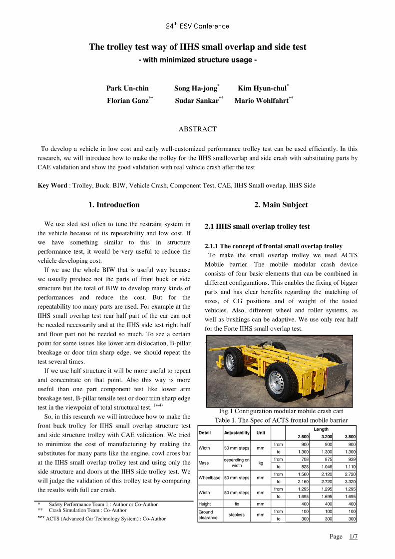
To make the small overlap trolley we used ACTS Mobile barrier. The mobile modular crash device consists of four basic elements that can be combined in different configurations. This enables the fixing of bigger parts and has clear benefits regarding the matching of sizes, of CG positions and of weight of the tested vehicles. Also, different wheel and roller systems, as well as bushings can be adaptive. We use only rear half for the Forte IIHS small overlap test.
Fig.1 Configuration modular mobile crash cart Table 1. The Spec of ACTS frontal mobile barrier
* Safety Performance Team 1 : Author or Co-Author ** Crash Simulation Team : Co-Author
*** ACTS (Advanced Car Technology System) : Co-Author
2.600 3.200 3.800
from 900 900 900
to 1.300 1.300 1.300
from 708 875 939
to 828 1.046 1.110
from 1.560 2.120 2.720
to 2.160 2.720 3.320
from 1.295 1.295 1.295
to 1.695 1.695 1.695
Height fix mm 400 400 400
from 100 100 100
to 300 300 300
Detail Adjustability
depending on width
Length
Mass
Width
Unit
mm
mm
mm
mm
kg
Ground clearance
50 mm steps
stepless
50 mm steps
50 mm stepsWheelbase
Width
24th ESV Conference
Page 2/7
Its frame mass can be adjusted from 700kg to 2,800kg and additional mass can be adaptive and adjusted. Statistic simulation can be done for a longitudinal beam with 600kN force and a cross beam with 400kN. Also crash panel and basic frame can be adjusted with step less. With this barrier, we decided to use the front Forte BIW from the forward to right in front of b-pillar. If we use the door and B-pillar the validation would be better but for the future use to minimize the part we did it. The cut area will be Also, we decided to remove all the trim an chassis parts except the parts related to the moving and the connection of engine to reduce the cost and improve the repeatability. Those parts are front wheels, lower arms, suspensions, a roll rod, an engine mounting, a transmission mounting, etc. The engine, front doors, cowl cross beam, delta glass and the first roof cross beam will be substituted by appropriate designed material by CAE. In case of wind glass and front seat they are removed. We couldn't install the front seat because rear seat mounting is removed. We selected the Forte vehicle is the US model of 1.8 Nu engine auto transmission. This vehicle's intrusion is poor grade which has some deformation on the roofrail of B-pillar and the worst case of the deformation among the Hyundai-Kia vehicles, we believe if we are successful for the validation that can be available for the most of vehicles.
Fig.2 The concept of small overlap trolley
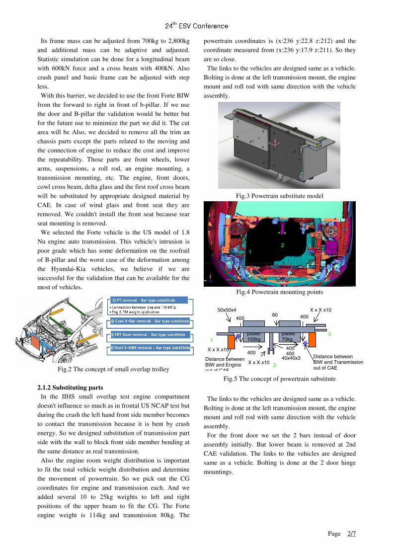
2.1.2 Substituting parts In the IIHS small overlap test engine compartment doesn't influence so much as in frontal US NCAP test but during the crash the left hand front side member becomes to contact the transmission because it is bent by crash energy. So we designed substitution of transmission part side with the wall to block front side member bending at the same distance as real transmission. Also the engine room weight distribution is important to fit the total vehicle weight distribution and determine the movement of powertrain. So we pick out the CG coordinates for engine and transmission each. And we added several 10 to 25kg weights to left and right positions of the upper beam to fit the CG. The Forte engine weight is 114kg and transmission 80kg. The
powertrain coordinates is (x:236 y:22.8 z:212) and the coordinate measured from (x:236 y:17.9 z:211). So they are so close. The links to the vehicles are designed same as a vehicle. Bolting is done at the left transmission mount, the engine mount and roll rod with same direction with the vehicle assembly.
Fig.3 Powetrain substitute model
Fig.4 Powetrain mounting points
Fig.5 The concept of powertrain substitute
The links to the vehicles are designed same as a vehicle. Bolting is done at the left transmission mount, the engine mount and roll rod with same direction with the vehicle assembly. For the front door we set the 2 bars instead of door assembly initially. But lower beam is removed at 2nd CAE validation. The links to the vehicles are designed same as a vehicle. Bolting is done at the 2 door hinge mountings.
3 1
2
weight plates 100kg
weight plates 70kg
50x50x4
X x X x10
X x X x10
X x X x10 40x40x3
1 3
2
1 3
2
1
2
3 1
2
400 400
400
400 400
Distance between BIW and Transmission out of CAE
Distance between BIW and Engine out of CAE
60
24th ESV Conference
Page 3/7
Fig.6 Front door mounting points
Fig.7 The concept of powertrain substitute
Also we designed the cowl crossbar substitute and 1st roof cross member to minimize the parts. When we get the structure assembly the cowl cross bar is not contained and the roof cross member is not the part of side structure like A-pillar and side sill.
Fig.8 The concept of cowl crossbar substitute All beams' material were S235 of plastic stress 235Mpa. And the surface area parts were welded to the trolley bracket
Fig.9 The concept of roof cross mebmer substitute
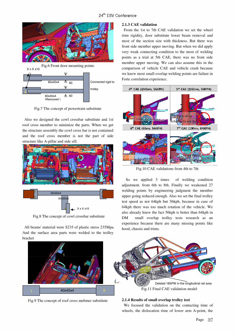
2.1.3 CAE validation From the 1st to 7th CAE validation we set the wheel rims rigidity, door substitute lower beam removal and most of the section size with thickness. But there was front side member upper moving. But when we did apply very weak connecting condition to the most of welding points as a trial at 5th CAE, there was no front side member upper moving. We can also assume this in the comparison of vehicle CAE and vehicle crash because we know most small overlap welding points are failure in Forte correlation experience.
3. Conclusion
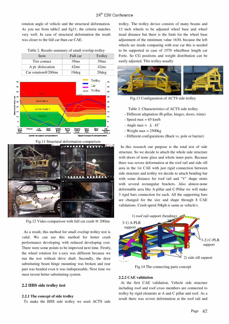
Fig.10 CAE validations from 4th to 7th So we applied 3 times of welding condition
adjustment. from 6th to 8th. Finally we weakened 27 welding points by engineering judgment the member upper going reduced enough. Also we set the final trolley test speed as not 64kph but 56kph, because in case of 64kph there was too much rotation of the vehicle. We also already knew the fact 56kph is better than 64kph in DM small overlap trolley tests research as an experience because there are many missing points like hood, chassis and trims.
Fig.11 Final CAE validation model
2.1.4 Results of small overlap trolley test We focused the validation on the contacting time of wheels, the dislocation time of lower arm A-point, the
1
2
60x40x4 1
60 Connected rigid to
trolley 2
60x40x4 (Removed )
60
50x50x4
50x50x4
X x X x10
1
2
2 1 40x40x4
X x X x10
7th CAE (100ms, 64KPH) 6th CAE (65ms, 56KPH)
4th CAE (@45ms, 56KPH) 5th CAE (@65ms, 56KPH)
In case of no
welditng failure no MBR UPR moving
Condition1
MBR UPR moving
Condition2
MBR UPR moving,
Deleted 18SPW in the longitudinal rail area
24th ESV Conference
Page 4/7
rotation angle of vehicle and the structural deformation. As you see from table2 and fig11, the criteria matches very well. In case of structural deformation the result was closer to the full car than car CAE.
Table 2. Results summary of small overlap trolley
Item Full car Trolley
Tire contact 39ms 39ms
A pt. dislocation 42ms 42ms
Car rotation@200ms 19deg 20deg
Fig.11 Structural deformation comparison
Fig.12 Video comparison with full car crash @ 200ms
As a result, this method for small overlap trolley test is valid. We can use this method for better crash performance developing with reduced developing cost. There were some points to be improved next time. Firstly, the wheel rotation for x-axis was different because we run the test without drive shaft. Secondly, the door substituting beam hinge mounting was broken and rear part was bended even it was indispensable. Next time we must invent better substituting system.
2.2 IIHS side trolley test
2.2.1 The concept of side trolley To make the IIHS side trolley we used ACTS side
trolley. The trolley device consists of many beams and 13 inch wheels to be adjusted wheel base and wheel tread distance but there is the limit for the wheel base adjustment of the minimum value 1630, because the left wheels are inside comparing with rear car this is needed to be supported in case of 1570 wheelbase length car Forte. So CG positions and weight distribution can be easily adjusted. This trolley usually
Fig.13 Configuration of ACTS side trolley
Table 3. Characteristics of ACTS side trolley - Different adaptation (B-pillar, hinges, doors, trims) - Speed max = 65 km/h
- Angle max = ± 45°
- Weight max = 2500kg - Different configurations (Buck vs. pole or barrier) In this research our purpose is the total test of side structure. So we decide to attach the whole side structure with doors of none glass and whole inner parts. Because there was severe deformation at the roof rail and side sill area in the 1st CAE with just rigid connection between side structure and trolley we decide to attach bending bar with some distance for roof rail and "V" shape struts with several rectangular brackets. Also almost-none deformable area like A-pillar and C-Pillar we will make 3 rigid bars connection for each. All the supporting bars are changed for the size and shape through 8 CAE validations. Crash speed 50kph is same as vehicle's.
Fig.14 The connecting parts concept
2.2.2 CAE validation At the first CAE validation, Vehicle side structure including roof and roof cross members are connected to trolley by rigid elements at A and C pillar and roof. As a result there was severe deformation at the roof rail and
Trolley
Car
Trolley
CAE
1) roof rail support (bending)
2) side sill support
3-2) C-PLR support
3-1) A-PLR support
24th ESV Conference
Page 5/7
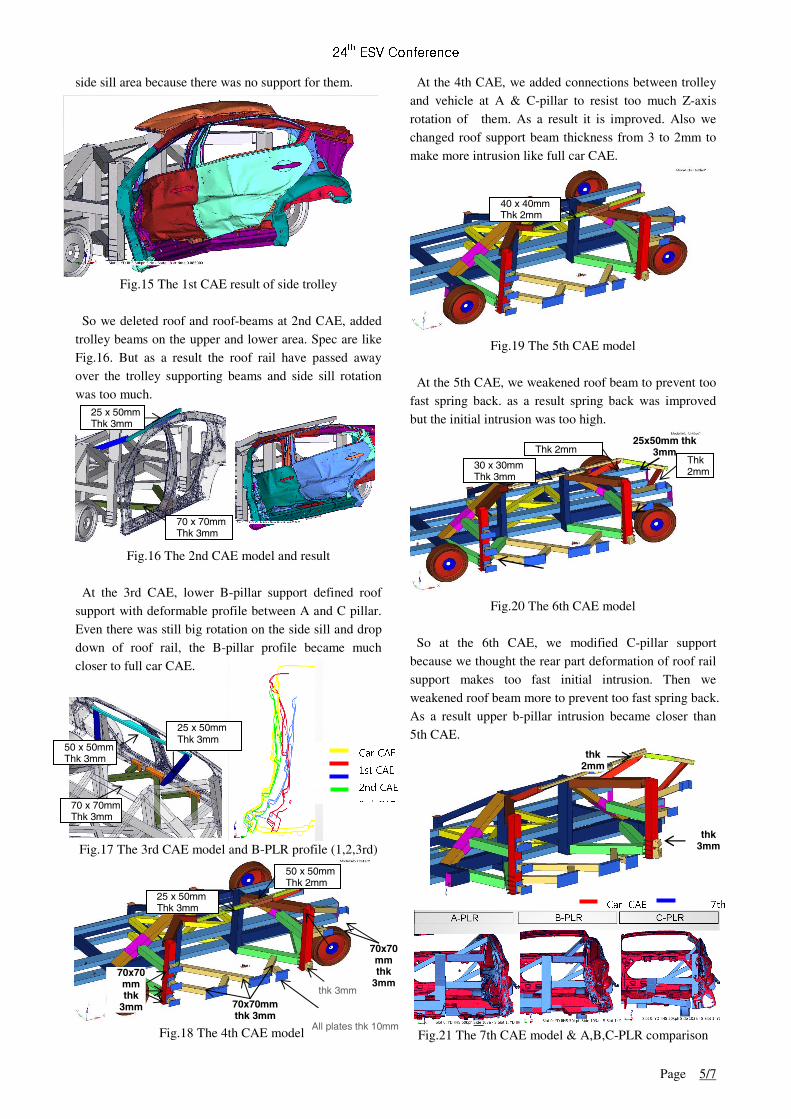
side sill area because there was no support for them.
Fig.15 The 1st CAE result of side trolley So we deleted roof and roof-beams at 2nd CAE, added trolley beams on the upper and lower area. Spec are like Fig.16. But as a result the roof rail have passed away over the trolley supporting beams and side sill rotation was too much.
Fig.16 The 2nd CAE model and result
At the 3rd CAE, lower B-pillar support defined roof support with deformable profile between A and C pillar. Even there was still big rotation on the side sill and drop down of roof rail, the B-pillar profile became much closer to full car CAE. Troll Fig.17 The 3rd CAE model and B-PLR profile (1,2,3rd)
Fig.18 The 4th CAE model
At the 4th CAE, we added connections between trolley and vehicle at A & C-pillar to resist too much Z-axis rotation of them. As a result it is improved. Also we changed roof support beam thickness from 3 to 2mm to make more intrusion like full car CAE.
Fig.19 The 5th CAE model
At the 5th CAE, we weakened roof beam to prevent too fast spring back. as a result spring back was improved but the initial intrusion was too high.
Fig.20 The 6th CAE model
So at the 6th CAE, we modified C-pillar support because we thought the rear part deformation of roof rail support makes too fast initial intrusion. Then we weakened roof beam more to prevent too fast spring back. As a result upper b-pillar intrusion became closer than 5th CAE.
Fig.21 The 7th CAE model & A,B,C-PLR comparison
25 x 50mm Thk 3mm
70 x 70mm Thk 3mm
40 x 40mm Thk 2mm
30 x 30mm Thk 3mm
Thk 2mm 25x50mm thk
3mm Thk 2mm
thk 3mm
thk 2mm
70 x 70mm Thk 3mm
50 x 50mm Thk 3mm
25 x 50mm Thk 3mm
Car CAE
1st CAE
2nd CAE
3 d CAE
`
25 x 50mm Thk 3mm
50 x 50mm Thk 2mm
70x70mm thk 3mm
All plates thk 10mm
70x70mm thk
3mm 70x70mm thk
3mm
thk 3mm
Car CAE 7th
24th ESV Conference
Page 6/7
At the 7th CAE, we strengthen the rear of roof beam by adding one box and also added new box between trolley and sill at C-pillar to prevent C-pillar partial intrusion. As a result we got the successful validation to make the trolley. There were still some points not validated partially like front & rear door beltline bending point and B-pillar upper & lower rotation but even the full CAE is not At the 8th CAE, we changed all the beams material from S355 to S235 because we cannot get the S355 soon. Also we changed some rigid parts to real modeling. As a result the intruding speed and permanent deformation was closer to the full car CAE than 7th CAE. 5)~6)
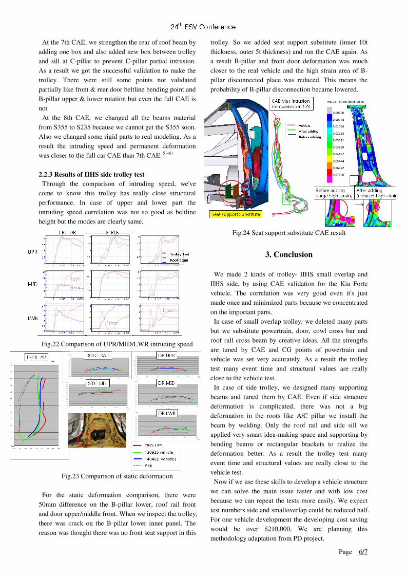
2.2.3 Results of IIHS side trolley test Through the comparison of intruding speed, we've come to know this trolley has really close structural performance. In case of upper and lower part the intruding speed correlation was not so good as beltline height but the modes are clearly same. Fig.22 Comparison of UPR/MID/LWR intruding speed
Fig.23 Comparison of static deformation
For the static deformation comparison, there were 50mm difference on the B-pillar lower, roof rail front and door upper/middle front. When we inspect the trolley, there was crack on the B-pillar lower inner panel. The reason was thought there was no front seat support in this
trolley. So we added seat support substitute (inner 10t thickness, outer 5t thickness) and run the CAE again. As a result B-pillar and front door deformation was much closer to the real vehicle and the high strain area of B-pillar disconnected place was reduced. This means the probability of B-pillar disconnection became lowered.
Fig.24 Seat support substitute CAE result
3. Conclusion
We made 2 kinds of trolley- IIHS small overlap and IIHS side, by using CAE validation for the Kia Forte vehicle. The correlation was very good even it's just made once and minimized parts because we concentrated on the important parts. In case of small overlap trolley, we deleted many parts but we substitute powertrain, door, cowl cross bar and roof rall cross beam by creative ideas. All the strengths are tuned by CAE and CG points of powertrain and vehicle was set very accurately. As a result the trolley test many event time and structural values are really close to the vehicle test. In case of side trolley, we designed many supporting beams and tuned them by CAE. Even if side structure deformation is complicated, there was not a big deformation in the roots like A/C pillar we install the beam by welding. Only the roof rail and side sill we applied very smart idea-making space and supporting by bending beams or rectangular brackets to realize the deformation better. As a result the trolley test many event time and structural values are really close to the vehicle test. Now if we use these skills to develop a vehicle structure we can solve the main issue faster and with low cost because we can repeat the tests more easily. We expect test numbers side and smalloverlap could be reduced half. For one vehicle development the developing cost saving would be over $210,000. We are planning this methodology adaptation from PD project.
0 0.025 0.05 0.0750
2.5
5
7.5
10
0 0.025 0.05 0.0750
2.5
5
7.5
10
0 0.025 0.05 0.075
0
2
4
6
8
Error
B-PLR FRT DR
UPR
MID
LWR
0 0.025 0.05 0.0750
2.5
5
7.5
10
0 0.025 0.05 0.0750
5
10
15
20
0 0.025 0.05 0.0750
2.5
5
7.5
10
12.5
-
0 0.025 0.05 0.0750
2.5
5
7.5
10
0 0.025 0.05 0.0750
2.5
5
7.5
10
0 0.025 0.05 0.0750
2
4
6
8
Rear
Error
Error
Trolley Test
Roof beam
24th ESV Conference
Page 7/7
Patent: Be submitted "Efficient IIHS
smalloverlap structure trolley", "Efficient IIHS side structure trolley"
References 1. Jason R. Kerrigan "Design of a Dynamic Rollover
Test System" UVA Center for Applied Biomechanics, 2011
2. Jeff R. Crandall, "Reproducing the Structural Intrusion of Frontal Offset Crashes in the Laboratory Sled Test Environment" University of Virginia, 2014
3. P. Michael Miller II, "A Compact Sled System for Linear Impact, Pole Impact, and Side Impact Testing" MGA Research Corp.,2002
4. Patrick M. Miller, "Evaluation Methodologies for Automobile Side Impact DevelopmentMGA Research Corp. ",1993
5. Karl Hoffmann, "Eine Einfüfrung in die Technik des Messens mit Dehnungsmeßstreifen", Herausgeber: Hottinger Baldwin Messtechnik GmbH, Sarmtadt
6. Herausgegeben von W.Beitz und K.-H., "DUBBEL TASCHENBUCH FÜR DEN MASCHINENBAU" 20. AUFLAGE
■ Author ■
Park Un-chin Song Ha-jong Kim Hyun-chul Florian Ganz Sudar Sankar Mario Wohlfahrt
Photograph
Photograph
Photograph
Photo graph
Photograph
Photograph