the testing of astronomical telescope optics...the testing of astronomical telescope mirrors page 2...
TRANSCRIPT
The Testing of Astronomical Telescope Mirrors
Page 1
The Testing of Astronomical Telescope Optics by
John R Nichol BSc MSc
Introduction
The purpose of the following article is to give an overview of the various methods of
testing astronomical telescope mirrors, it will be of interest to those seeking an overview
of the test methods but not necessarily wishing to actually perform the tests. It is hoped
that it will inspire those already using the more accessible tests to try something a little
more advanced. It is sobering to think that tests like interferometry, once the province of
professionals, is now becoming commonplace amongst amateur telescope makers. One
thing that all of the tests have in common is that they benefit from experience and skill to
give reliable results. The author has had experience in using all of the tests described.
The Foucault Test
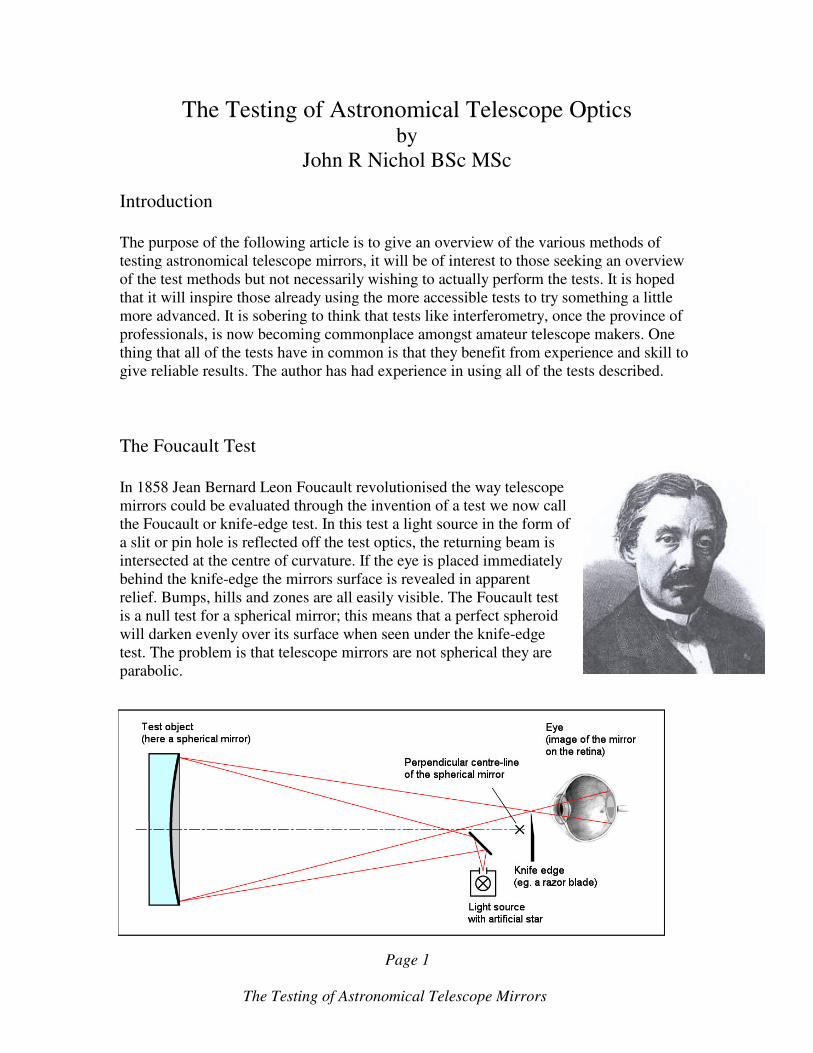
In 1858 Jean Bernard Leon Foucault revolutionised the way telescope
mirrors could be evaluated through the invention of a test we now call
the Foucault or knife-edge test. In this test a light source in the form of
a slit or pin hole is reflected off the test optics, the returning beam is
intersected at the centre of curvature. If the eye is placed immediately
behind the knife-edge the mirrors surface is revealed in apparent
relief. Bumps, hills and zones are all easily visible. The Foucault test
is a null test for a spherical mirror; this means that a perfect spheroid
will darken evenly over its surface when seen under the knife-edge
test. The problem is that telescope mirrors are not spherical they are
parabolic.

The Testing of Astronomical Telescope Mirrors
Page 2
Under the Foucault test a parabolic mirror displays the so-called doughnut appearance, as
the shadows produced resemble a doughnut. Incidentally, long focus telescope mirrors
can be left spherical and work well, this is because at longer focal lengths the difference
between a spherical and parabolic mirror can be less that ¼ lambda on the wave front,
which in very general terms conforms with the definition of a good quality optical
surface.
Foucault test images of a 22-inch F4 paraboloid showing ‘doughnut’ shadows.
The Foucault knife-edge test is qualitative, that is it does
not give us any numbers to describe the surface of the
mirror. The test can be made quantitative by using it in
combination with a zonal mask or Couder screen. Here a
piece of cardboard is cut to expose zones as shown in the
picture. As the knife-edge is moved backwards and
forwards zones of the same radius are seen to null, or
darken evenly as the knife edge moves. By carefully
measuring the positions at which the null occurs using a
micrometer and by knowing the positions of the zones it is
possible to give a quantitative analysis of the mirrors
surface. This method is widely used by amateur telescope
makers. Unfortunately it is not without its problems. It
requires considerable skill to make accurate judgments about when nulling of the zones
occurs; the test looks only at certain areas of the mirror and not all of it. The mirror can
be rotated to reduce this problem. This test is tedious and tiring to perform and becomes
less dependable with decreasing focal length, never the less the test has been employed in
professional optical shops to produce optics which have be been shown to give excellent
images in the field. Useful software tools are available to assist with the analysis of the
test optic.

The Testing of Astronomical Telescope Mirrors
Page 3
The Ronchi Test
In 1922 Vasco Ronchi proposed the test now named after him. It is
a variation on the Foucault test. The light source is a slit which is
reflected off the test optic, and the returning beam is allowed to
pass through a transparent screen with a series of dark parallel
lines marked on its surface. The appearance of the Ronchi bands
reveals much information about the surface of the optics under
test. Again, the test is qualitative; no numbers describing the
mirrors surface are produced. It is possible to use a computer to
generate the appearance of the Ronchi bands at different positions
either side of the centre of curvature, these can be compared with
the observed images and judgements made about the surface of the
optic. For someone new to telescope mirror making this is perhaps
the easiest test to perform that can be regarded as semi-
quantitative.
Examples of ronchi bands
A spherical mirror tested at the centre of
curvature, the Ronchi bands appear as
straight lines.
A parabolic mirror with the Ronchi ruling
just inside of the centre of curvature.
A parabolic mirror as seen with the Ronchi
ruling just outside of the centre of
curvature.
A parabolic mirror showing a turned down
edge, Ronchi ruling just inside of the centre
of curvature.

The Testing of Astronomical Telescope Mirrors
Page 4
For further information see:
http://www.atm-workshop.com/ronchi-test.html
http://www.bbastrodesigns.com/ronchi.html
The Dall and Ross null tests.
Both of these tests require additional optics in the form of a high quality plano-convex
lens. This lens is used to introduce spherical aberration equal in size but opposite in sign
to that produced by the parabolic mirror under test. The result of this is that the parabolic
mirror under test appears like a spherical mirror when it is fully figured. The
arrangement for the Dall test is such that the returning image is viewed off axis, as a
result unwanted astigmatism arises which complicates interpretation of the results. The
test works best with longer focal lengths (approximately F6 and above).
The Ross null test layout.
The Dall null test layout.
Position of the
light source and
Knife edge
Ross lens
Test mirror
Light source
Knife-edge
and eye
Dall lens
Test mirror

The Testing of Astronomical Telescope Mirrors
Page 5
The advantage of the Ross test is that it is on axis, the light from the source passing
through the lens before and after reflection therefore, assuming correct alignment, the off-
axis effects present in the Dall test are not seen. Being null tests both of these tests offer
the advantage that interpreting the result is relatively straight forward for example, when
used in combination with a ronchi ruling the ideal parabolic mirror shows straight bands
when correctly figured. When under corrected the bands appear bowed towards the
centre, when over corrected the bands appear bowed towards the edge. Both tests are
qualitative in nature yet are generally well regarded and are used by professional
opticians as an aid to testing parabolic mirrors.
The disadvantage of both tests is that they require careful and accurate measurements of
certain spacings in the test set up to be made. In the case of the Dall test the lens to light
source slit has to be accurately set up, this may be accomplished by mounting the lens
and light source in a sliding tube with lugs on the outside. These may be used to make
measurements about the spacing of the lens and light source slit. The lens used in the
Ross test is much larger than the Dall lens, typically 80 mm in diameter as opposed to the
25mm or so of the Dall lens. In the Ross test, accurate measurements of the distance
between the test mirror and lens, together with the distance between the lens and knife-
edge and light source, must be made. In practise these measurements are not too difficult
to make with a little care. Both tests have the advantage of being able to test a range of
aspheric surfaces other than parabolic curves including ellipsoids and hyperboloids which
are employed in some cassegrain telescope configurations. For reliable results lenses used
in either of these tests must be well made or from a reputable source. A lens tested with
an interferometer and having certification is preferable.
For further information see:
http://www.ceravolo.com/testing/ross_null.pdf
http://www.atm-workshop.com/dall-null.html
The Autocollimation Test
The autocollimation or double pass null test is well regarded and widely used in
professional optical shops for testing parabolic mirrors. Like the Ross and Dall tests it is a
null test so the ideal parabolic mirror shows straight bands when use with a Ronchi ruling
or is seen to darken uniformly when viewed with the knife edge. However, the test is
twice as sensitive as the other null tests as light is reflected off the test optic twice, this
makes it a very powerful test. The price to pay for this sensitivity is that the test set up
requires a high quality optical flat at least as big as the mirror under test, such an item is
difficult to make and very expensive to buy. With the autocollimation test the mirror is
tested at it’s focus unlike the Ross and Dall tests which are at the centre of curvature.
The Testing of Astronomical Telescope Mirrors
Page 6
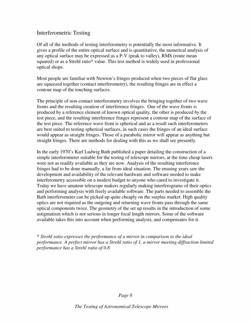
Optical layout for the Autocollimation test
In fact the flat reference mirror does not have to be perfectly flat it can be slightly
convex or concave but it must have a very smooth surface at least as good as that
expected of the test optic. The advantage of a null test is that at any given point it is very
easy to interpret the condition of the mirror’s surface and take appropriate remedial
action. An optician proceeds as if he is figuring a spherical mirror and is looking for
straight bands with a Ronchi ruling or a null with the knife-edge.
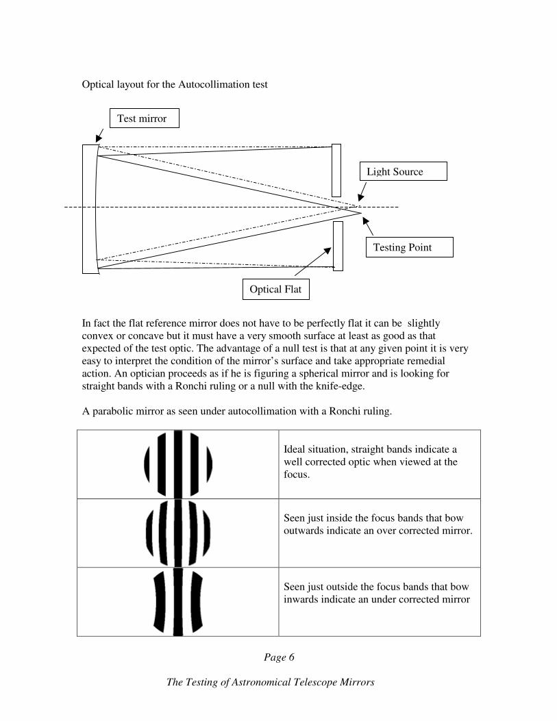
A parabolic mirror as seen under autocollimation with a Ronchi ruling.
Ideal situation, straight bands indicate a
well corrected optic when viewed at the
focus.
Seen just inside the focus bands that bow
outwards indicate an over corrected mirror.
Seen just outside the focus bands that bow
inwards indicate an under corrected mirror
Light Source
Testing Point
Test mirror
Optical Flat
The Testing of Astronomical Telescope Mirrors
Page 7
The double pass autocollimation test is not a quantitative test, but none the less it is
widely used in professional optical shops as it allows the production of high quality
optics within a sensible time scale.
The Star Test.
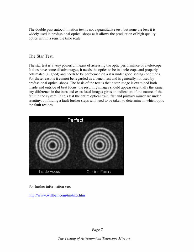
The star test is a very powerful means of assessing the optic performance of a telescope.
It does have some disadvantages, it needs the optics to be in a telescope and properly
collimated (aligned) and needs to be performed on a star under good seeing conditions.
For these reasons it cannot be regarded as a bench test and is generally not used by
professional optical shops. The basis of the test is that a star image is examined both
inside and outside of best focus; the resulting images should appear essentially the same,
any difference in the intra and extra focal images gives an indication of the nature of the
fault in the system. In this test the entire optical train, flat and primary mirror are under
scrutiny, on finding a fault further steps will need to be taken to determine in which optic
the fault resides.
For further information see:
http://www.willbell.com/tm/tm5.htm
The Testing of Astronomical Telescope Mirrors
Page 8
Interferometric Testing
Of all of the methods of testing interferometry is potentially the most informative. It
gives a profile of the entire optical surface and is quantitative, the numerical analysis of
any optical surface may be expressed as a P-V (peak to valley), RMS (route mean
squared) or as a Strehl ratio* value. This test method is widely used in professional
optical shops.
Most people are familiar with Newton’s fringes produced when two pieces of flat glass
are squeezed together (contact interferometry), the resulting fringes are in effect a
contour map of the touching surfaces.
The principle of non-contact interferometry involves the bringing together of two wave
fronts and the resulting creation of interference fringes. One of the wave fronts is
produced by a reference element of known optical quality, the other is produced by the
test piece, and the resulting interference fringes represent a contour map of the surface of
the test piece. The reference wave front is spherical and as a result such interferometers
are best suited to testing spherical surfaces, in such cases the fringes of an ideal surface
would appear as straight fringes. Those of a parabolic mirror will appear as anything but
straight fringes. There are methods for dealing with this as we shall see presently.
In the early 1970’s Karl Ludwig Bath published a paper detailing the construction of a
simple interferometer suitable for the testing of telescope mirrors, at the time cheap lasers
were not as readily available as they are now. Analysis of the resulting interference
fringes had to be done manually, a far from ideal situation. The ensuing years saw the
development and availability of the relevant hardware and software needed to make
interferometry accessible on a modest budget to anyone who cared to investigate it.
Today we have amateur telescope makers regularly making interferograms of their optics
and performing analysis with freely available software. The parts needed to assemble the
Bath interferometer can be picked up quite cheaply on the surplus market. High quality
optics are not required as the outgoing and returning wave fronts pass through the same
optical components twice. The geometry of the set up results in the introduction of some
astigmatism which is not serious in longer focal length mirrors. Some of the software
available takes this into account when performing analysis, and compensates for it.
* Strehl ratio expresses the performance of a mirror in comparison to the ideal
performance. A perfect mirror has a Strehl ratio of 1, a mirror meeting diffraction limited
performance has a Strehl ratio of 0.8

The Testing of Astronomical Telescope Mirrors
Page 9
The optical Layout of the Bath Interferometer.
The diagram shows the paths of the outgoing rays from the interferometer to the test
surface.
The diagram below shows the paths of the rays returning from a test surface. The rays
from the bottom of the cube re-enter the beam splitter through the biconvex lens. The
rays from biconvex lens re-enter the beam splitter at the bottom without passing through
the lens again.
Biconvex
lens
Mirror
under
test
Laser pointer
Beamsplitter
cube
Flat mirror
Outgoing and returning beams recombine
The Testing of Astronomical Telescope Mirrors
Page 10
The outgoing and returning rays re-combine in the beam splitter to produce the
interference fringes.
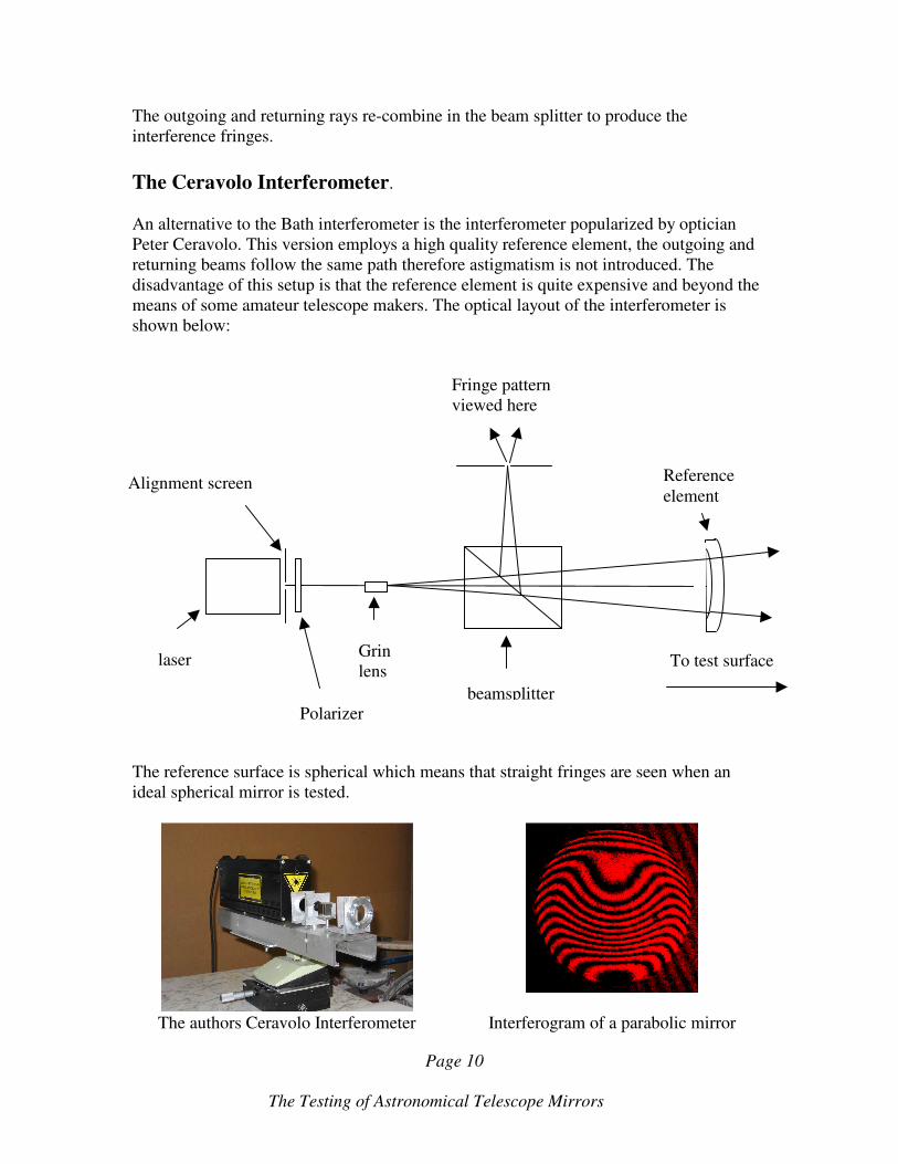
The Ceravolo Interferometer.
An alternative to the Bath interferometer is the interferometer popularized by optician
Peter Ceravolo. This version employs a high quality reference element, the outgoing and
returning beams follow the same path therefore astigmatism is not introduced. The
disadvantage of this setup is that the reference element is quite expensive and beyond the
means of some amateur telescope makers. The optical layout of the interferometer is
shown below:
The reference surface is spherical which means that straight fringes are seen when an
ideal spherical mirror is tested.
The authors Ceravolo Interferometer Interferogram of a parabolic mirror
beamsplitter
Grin
lens
Polarizer
Alignment screen
laser
Reference
element
To test surface
Fringe pattern
viewed here

The Testing of Astronomical Telescope Mirrors
Page 11
Testing an aspheric mirror with a spherical wavefront Interferometer.
The objective of interferometry is to produce an image of the fringe pattern, called an
interferogram, this is usually in the form of a digital image which can be used by
appropriate software to calculate the surface profile. In practice, when using the software,
the edge of the mirror is defined and the fringes are then traced either manually or
automatically, once this is done the software calculates Zernikes, these are numbers that
quantify the various aberrations present in the optic. An overall view of the optics is
presented in terms of it’s Strehl ratio, RMS and PTV values.
Both of the interferometers discussed so far are best suited to testing spherical mirrors as
these show straight fringe patterns which are relatively easy to interpret. Unfortunately,
many surfaces employed in astronomical telescopes are not spherical; they are aspheric
surfaces such as paraboloids, ellipsoids and hyperboloids.
For longer focal length mirrors this is not a problem as software can employ artificial
nulling, a process which compensates mathematically for the difference between the test
optic and a spherical one. This process starts to become less reliable with decreasing
focal length and as a result alternative solutions must be found. From the notes on the
autocollimation test you will recall that this is a null test for a paraboloid, one solution is
to use an interferometer in conjunction with the autocollimation test, an ideal parabolic
mirror produces a spherical wavefront in the autocollimation test, and such a wavefront
will produce straight fringes when viewed with the interferometers described here. It
should be noted that in practice very careful alignment of the optics in needed in order to
avoid the introduction of aberrations, which can potentially confuse the analysis. Testing
in this mode can result in the test wavefront being fainter than the reference wavefront
due to the double reflection off the flat and the fact that the test mirror is uncoated, as a
result fringes may be faint making analysis difficult if not impossible.
Another useful combination of tests involves the use of a Ross null lens and an
interferometer. This combination has the advantage over autocollimation in that it can be
used with aspheric surfaces other than a paraboloid. This is achieved by varying the
spacing of the elements. Again the setup is quite sensitive to alignment problems.
For further information see;
http://www.ceravolo.com/testing/interferometer.htm
http://starryridge.com/mediawiki-1.9.1/index.php?title=Bath_Interferometer