the tcp/ip architectureica interface between a layer and the layer above ‐sap (service access...
TRANSCRIPT
CN2
© Jean-Yves Le Boudec, EPFL
ÉCOLE POLYTECHNIQUE FÉDÉRALE DE LAUSANNE
The TCP/IP ArchitectureJean‐Yves Le Boudec
Fall 2009
1

CN2
© Jean-Yves Le Boudec, EPFL
* Objective
Understand Layered Model of Communication SystemsKnow the function of every layerKnow the function of every layer
Why and What – we will see the How in other modules.
Understand basic performance issues
* Contents1. The Layered model of the Internet, Packet Switching2. Protocol, service and other definitions3. All you need to know about the physical layer
2
CN2
© Jean-Yves Le Boudec, EPFL
Why was TCP/IP invented ?
By « network » we mean one of the followingInternetInternet
SMS
telephone
We focus on the Internet. Similar concepts are used in other networks, with a different terminology.Communication networks use a layered approach
3

CN2
© Jean-Yves Le Boudec, EPFL
Layered Architecture
TCP/IP is a layered architectureWhy ?y
Divide and conquer – make things manageable
What is it ? Application
TransportCommunication
Interconnection
Transport
Network
Links
4
PhysicalDistance

CN2
© Jean-Yves Le Boudec, EPFL
Application Layer helps people and machines communicate
Uses well defined “protocols” (setUses well defined protocols (set of rules and messages)ex: HTTPIn the simplest case, involves 2 computers
user clicks:http://www.zurich.ibm.com/RZ.html
If you write an application that uses the network, you define your own “Application Layer”
Web serverIP addr = 193.5.61.131
5
data (HTML page)
GET www.zurich.ibm.com/RZ.html
CN2
© Jean-Yves Le Boudec, EPFL
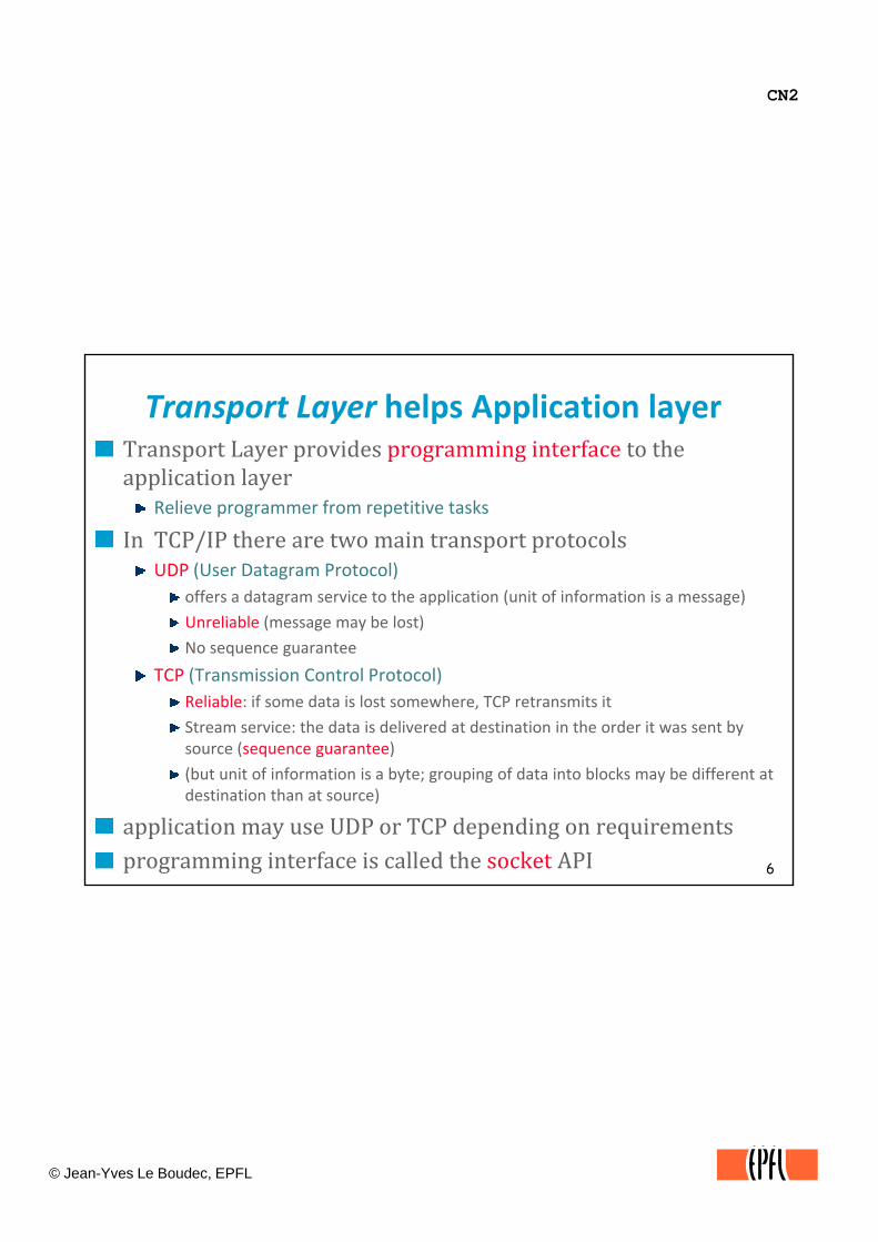
Transport Layer helps Application layerTransport Layer provides programming interface to the application layerpp y
Relieve programmer from repetitive tasks
In TCP/IP there are two main transport protocolsUDP (User Datagram Protocol)
offers a datagram service to the application (unit of information is a message)
Unreliable (message may be lost)Unreliable (message may be lost)
No sequence guarantee
TCP (Transmission Control Protocol)Reliable: if some data is lost somewhere, TCP retransmits it
Stream service: the data is delivered at destination in the order it was sent by source (sequence guarantee)
6
source (sequence guarantee)
(but unit of information is a byte; grouping of data into blocks may be different at destination than at source)
application may use UDP or TCP depending on requirementsprogramming interface is called the socket API

CN2
© Jean-Yves Le Boudec, EPFL
* UDP is used via a Socket Library
The socket library provides a programming interface to TCP and UDP
client
socket();
server
socket();UDPThe figure shows toy client and server UDP programs. The client sends one string of chars to the server, which simply receives (and displays) it.
socket();
bind();
sendto();
socket();
bind();
rcvfrom();
socket() creates a socket and returns a number (=file descriptor) if successfulbind() associates the local port number with the socketsendto() gives the destination IP address port number and the
close();
% ./udpClient <destAddr> bonjour les amis%
7
address, port number and the message to sendrecvFrom() blocks until one message is received for this port number. It returns the source IP address and port number and the message.
%
% ./udpServ &%

CN2
© Jean-Yves Le Boudec, EPFL
* TCP is used via a socket library
Example of a toy program (we will see more details later)
When client program uses the TCP send() function of the socket library, the library may break the
clientserverk t()
When client program uses the TCP send() function of the socket library, it knows that TCP will do all the necessary jobs to check that the server has indeed received the message If some data is lost in the
y y ymessage into pieces and deliver the pieces separately, but in sequence (stream service)
socket();socket();
bind();
connect();
d( i h ib / h l)
bind();
listen();
accept();
()
message. If some data is lost in the network, TCP will retransmit; the application program does not need to bother about it (reliable service)
8
send(GET www.zurich.ibm.com/RZ.html);
close();
receive();
close();
GET www.zurich.ibm.com/RZ.html
send(DATA …);DATA …
CN2
© Jean-Yves Le Boudec, EPFL
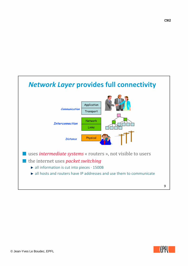
Network Layer provides full connectivity
Applic ti nApplication
Transport
Network
Links
Communication
Interconnection
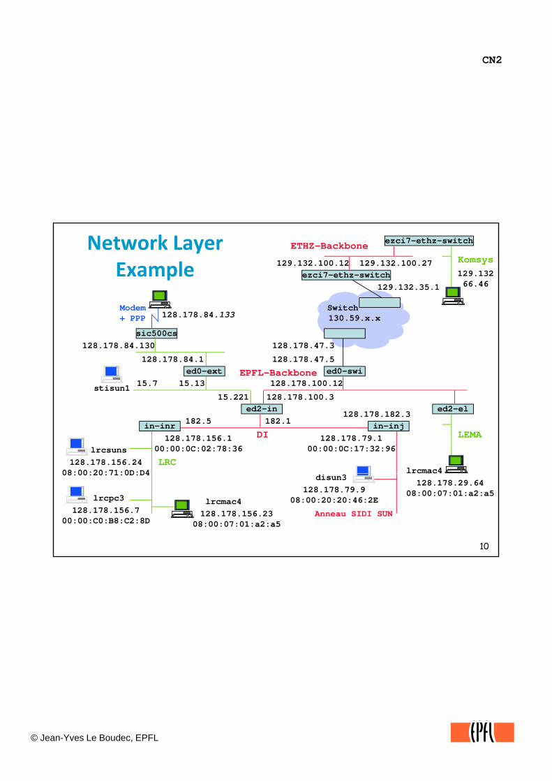
uses intermediate systems « routers », not visible to usersthe internet uses packet switching
PhysicalDistance
9
the internet uses packet switchingall information is cut into pieces ∙ 1500B
all hosts and routers have IP addresses and use them to communicate
CN2
© Jean-Yves Le Boudec, EPFL
129.13266.46
129.132.100.12
Network Layer Example
Modem S itch
ezci7-ethz-switch129.132.35.1
ezci7-ethz-switch
KomsysETHZ-Backbone
129.132.100.27
ed0-swi15.13 128.178.100.12
128.178.84.1ed0-ext EPFL-Backbone
sic500cs128.178.84.130
Modem+ PPP 128.178.84.133
stisun1 15.7
128.178.47.5
128.178.47.3
Switch130.59.x.x
lrcsuns128.178.156.24
08:00:20:71:0D:D4
in-inr128.178.156.1
00:00:0C:02:78:36128.178.79.1
00:00:0C:17:32:96
ed2-in182.1 in-inj
128.178.182.3182.5
128.178.100.3
LRC
15.221
DI
stisun1
ed2-el
LEMA
lrcmac4
10
08:00:20:71:0D:D4
lrcpc3128.178.156.7
00:00:C0:B8:C2:8DAnneau SIDI SUN
disun3128.178.79.9
08:00:20:20:46:2E
128.178.29.6408:00:07:01:a2:a5
128.178.156.2308:00:07:01:a2:a5
lrcmac4

CN2
© Jean-Yves Le Boudec, EPFL
* The Very First Computer Networks (Bitnet, SNA) used Store and Forward
T1
point to pointcables
1
T1
T2
“to T3: Hello”
mainframecomputer
terminals
2
T3
“From T1: Hello”
11

CN2
© Jean-Yves Le Boudec, EPFL
The Network Layer of the Internet uses Packet Switching ‐‐Why ?
Time diagram of store and forwardTime diagram of store and forward
12
CN2
© Jean-Yves Le Boudec, EPFL
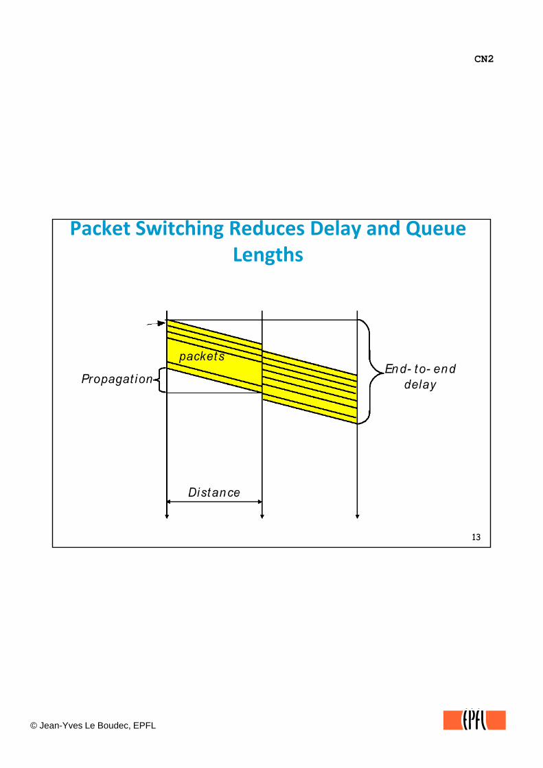
Packet Switching Reduces Delay and Queue Lengths
13
CN2
© Jean-Yves Le Boudec, EPFL
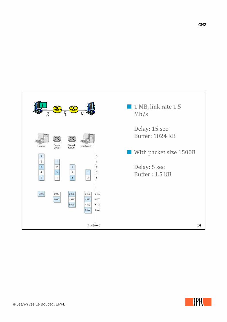
1 MB, link rate 1.5 Mb/s
Delay: 15 secBuffer: 1024 KB
With packet size 1500B
Delay: 5 secBuffer : 1.5 KB
14
CN2
© Jean-Yves Le Boudec, EPFL
Circuit vs Packet Switching
With packet switching, data packets can be carried together on the same link They are differentiated by addressingthe same link. They are differentiated by addressing information. Packet switching is the basis for all data networks today, including the Internet, public data networks such as Frame Relay or X.25, and even ATM. Packet switches have queues. Circuit switching is the way telephone networks operate. A circuit emulates the physical signals of a direct end‐to‐end cable. When computers are connected by a circuit switched network, they establish a direct data link over the circuit. This is used today for modem access to a data network.
15
yA network has intermediate systems (ISs): those are systems that send data to next ISs or to the destination. Using interconnected ISs saves cable and bandwidth. Intermediate systems are known under various terms depending on the
t t t (TCP/IP A l T lk ) it h (X 25 F
CN2
© Jean-Yves Le Boudec, EPFL
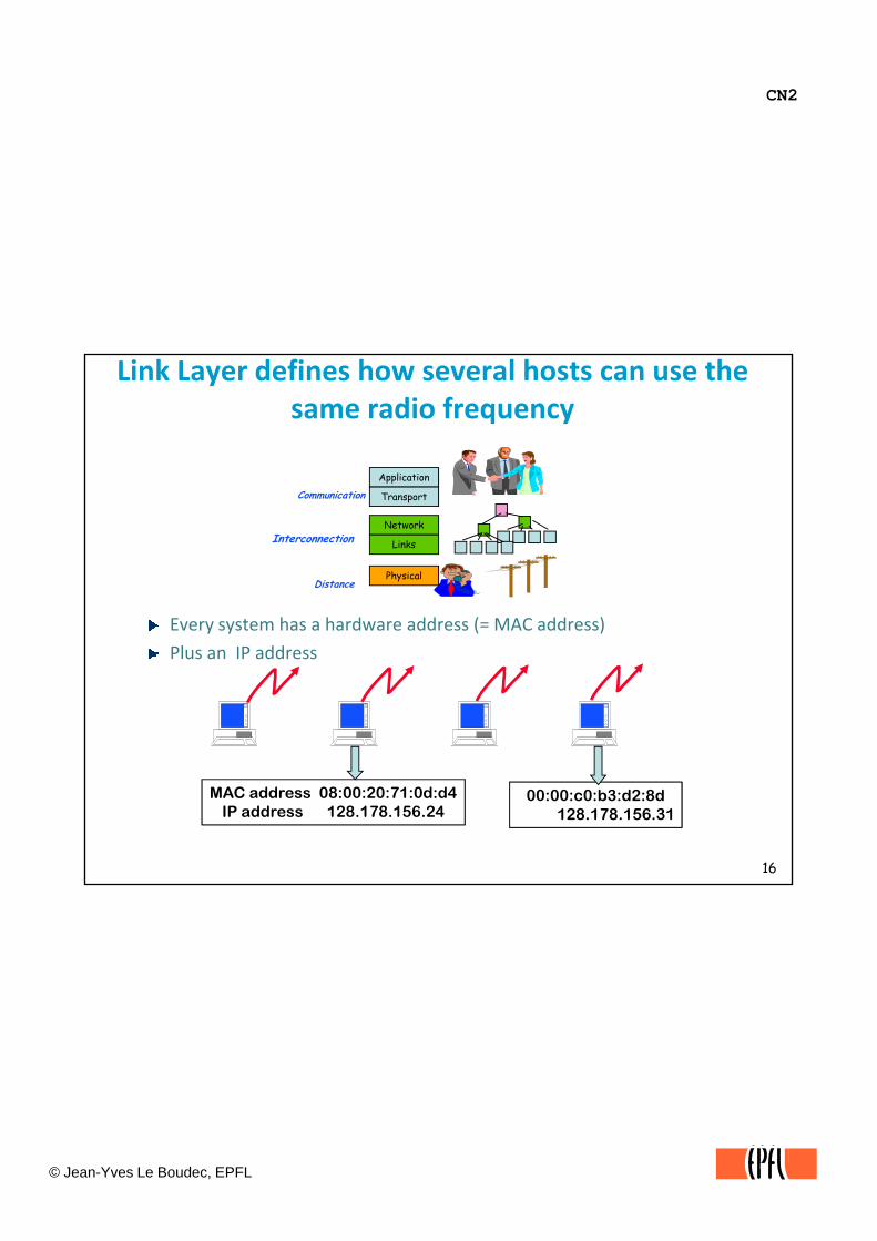
Link Layer defines how several hosts can use the same radio frequency
Application
E t h h d dd ( MAC dd )
Transport
Network
Links
PhysicalDistance
Communication
Interconnection
Every system has a hardware address (= MAC address)
Plus an IP address
16
MAC address 08:00:20:71:0d:d4IP address 128.178.156.24
00:00:c0:b3:d2:8d128.178.156.31

CN2
© Jean-Yves Le Boudec, EPFL
Physical Layer Transforms Bits and Bytes into Electromagnetic Waves
bits bitssignal
encoding decoding
Encoding of bits as physical signalsIs technology specific: there are several Ethernet physical layers
g g
17
Is technology specific: there are several Ethernet physical layers, several WLAN 802.11 physical layersAcoustic instead of electromagnetic is used under water

CN2
© Jean-Yves Le Boudec, EPFL
Web serverElaine
ApplicationApplication
Transport (TCP)
Application
send(s2, dataBlock)
1 2 3 4 5
Transport (TCP)
Application
read(s1, dataBlock)
1 2 3 4 5Router
Network (IP)
Link (WLAN)
1 2 3 4 5
Network (IP)
Link
1 2 3
Network (IP)
Link (WLAN)
2 3 4 5
18
( )
Physical
1 2 3 4 5
Physical
1 2 3
( )
Physical
2 3 4 5 1 2 3
CN2
© Jean-Yves Le Boudec, EPFL
Why do we call that stuff Layers ?
By the nature of communication, we have two types of interactions: between peers – and between layersinteractions: between peers and between layers
This is why we call this stuff a set of layers
19
CN2
© Jean-Yves Le Boudec, EPFL
2. Protocol, service and other fancy definitionsPeer entities
two (or more) instances of the same layer
Protocol and a PDU:the rules of the operation followed by peer entities
the data exchanged is called PDU (Protocol Data Unit)
there is one protocol (or more) at every layer
Examples of protocols are: TCP; UDP;IP; EthernetExamples of protocols are: TCP; UDP;IP; Ethernet
Service and a SDUthe interface between a layer and the layer above ‐ SAP (Service Access Point)
the interface data is called a SDU (Service Data Unit)
Connection
20
Connectiona protocol is connection oriented if the peer entity must be synchronized before exchanging useful data (connection set up); otherwise it is connectionless.The telephone system is connection oriented: before A can send some information to B, A has to call B (or vice versa) and say “hello”. The postal (mail) system is connectionless. If A wants to send some information to B, A can write a letter and mail it, even if B is not ready to read it.

CN2
© Jean-Yves Le Boudec, EPFL
Protocol ArchitectureSDU SDU
SAP
PDU PDU
protocolLayer n entity Layer n entity
serviceSAP
demultiplexing
Layer n-1
Networking functions are structured as a layered model:‐ layer n communicates with other layer n entities using layer n PDUs
21
layer n communicates with other layer n entities using layer n PDUs‐ layer n uses the service of layer n1 and offers a service to layer n+1.‐ entities at the same layer are said peer entities operation rules between peer entities are called protocol
Layering of protocol entities is reflected by the term of a protocol stack.
CN2
© Jean-Yves Le Boudec, EPFL
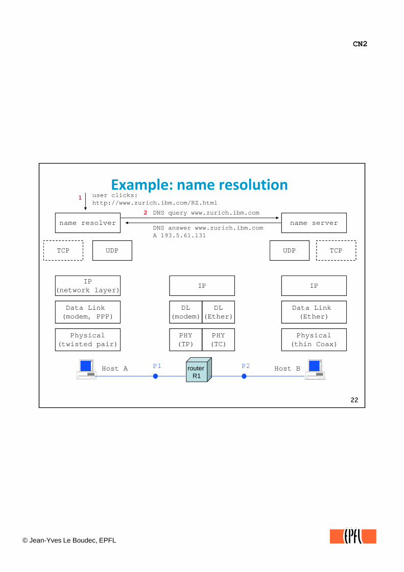
Example: name resolutionuser clicks:http://www.zurich.ibm.com/RZ.html
DNS query www.zurich.ibm.com
1
2
name resolver name serverDNS answer www.zurich.ibm.comA 193.5.61.131
name resolver
TCP UDP
IP
name server
TCPUDP
IPIP(network layer)(network layer)
Data Link (modem, PPP)
Physical(twisted pair)
IP
Data Link (Ether)
Physical(thin Coax)
IP
DL(modem)
PHY(TP)
DL(Ether)
PHY(TC)
22
( p ) ( )( ) ( )
router R1
Host A Host BP1 P2

CN2
© Jean-Yves Le Boudec, EPFL
Flow 2 illustrates the query/response protocol of the Domain Name System (DNS). The name resolver and the name server are two application programs, probably C programs making calls to the socket library. The programs use UDP, which is the non‐reliable transport protocol in the TCP/IP stack.
Let us apply the terminology on this example.“name resolver” uses the UDP service: it creates a request to send data to “name server”. “name server” is identified by its IP address (for example: 128.178.15.7). “name resolver” also knows that “name server” can be reached by means of port 53 (a well known convention used in the Internet). The SDU is the request, with the data. The transport‐PDU is called a datagram. It contains the data, the address and the port numbers. It is identified by 2 in the figure.numbers. It is identified by 2 in the figure.UDP creates a request to IP to send data to the name server machine identified by the IP address 128.178.15.7. The network‐PDU is called an IP packet. It contains the UDP datagram plus the IP addressing information (and some other information, see later).IP creates a request to send a data frame over the modem. The modem card creates a data‐link PDU, called a modem “frame”. The frame contains the IP packet, maybe compressed. Then the data link layer requests transmission of the frame; the physical l SDU i bi Th h i l l PDU i l i i l
23
layer SDU is a bit. The physical layer PDU is an electromagnetic signal. At the router
the data frame is received, understood as an IP packetIP reads the IP destination address (128.178.15.7) and decides to forward it over its Ethernet interfaceIP creates a request to send the data frame over the Ethernet. An Ethernet frame is created and sent to the name server machine
CN2
© Jean-Yves Le Boudec, EPFL
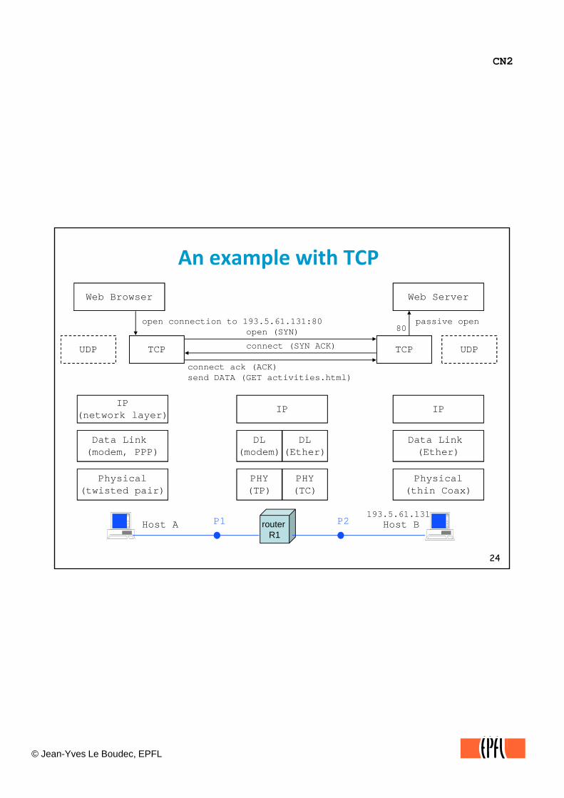
An example with TCP
Web Browser Web Server
UDP TCP UDPTCP
open connection to 193.5.61.131:80open (SYN)
connect (SYN ACK)
connect ack (ACK) send DATA (GET activities.html)
passive open80
(network layer)IP
(network layer)
Data Link (modem, PPP)
Physical
IP
Data Link (Ether)
Physical
IP
DL(modem)
PHY
DL(Ether)
PHY
24
(twisted pair) (thin Coax)(TP) (TC)
router R1
Host A Host BP1 P2193.5.61.131
CN2
© Jean-Yves Le Boudec, EPFL
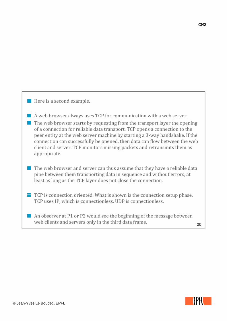
Here is a second example.
A web browser always uses TCP for communication with a web server.The web browser starts by requesting from the transport layer the opening of a connection for reliable data transport. TCP opens a connection to the peer entity at the web server machine by starting a 3‐way handshake. If the connection can successfully be opened, then data can flow between the web client and server. TCP monitors missing packets and retransmits them as appropriate.
The web browser and server can thus assume that they have a reliable data pipe between them transporting data in sequence and without errors, at least as long as the TCP layer does not close the connection.
TCP is connection oriented What is shown is the connection setup phase
25
TCP is connection oriented. What is shown is the connection setup phase. TCP uses IP, which is connectionless. UDP is connectionless.
An observer at P1 or P2 would see the beginning of the message between web clients and servers only in the third data frame.
CN2
© Jean-Yves Le Boudec, EPFL
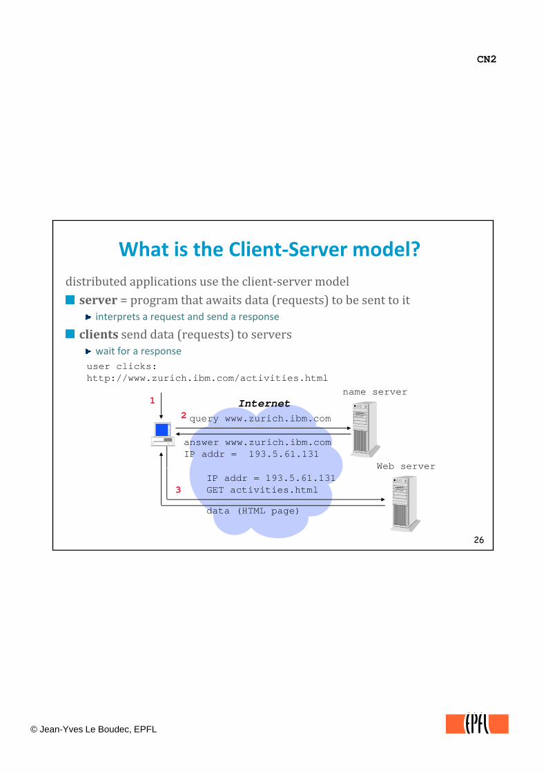
What is the Client‐Server model?distributed applications use the client‐server modelserver = program that awaits data (requests) to be sent to itserver program that awaits data (requests) to be sent to it
interprets a request and send a response
clients send data (requests) to serverswait for a response
user clicks:http://www.zurich.ibm.com/activities.html
query www.zurich.ibm.com
answer www.zurich.ibm.comIP addr = 193.5.61.131
1
2
name server
Web server
Internet
26
IP addr = 193.5.61.131GET activities.html
data (HTML page)
3
Web server

CN2
© Jean-Yves Le Boudec, EPFL
We use the terms “client” and “server” in the following sense.
When two entities say A and B, want to communicate, there is a boostrap problem: how can you initialize both A and B such that p p ythe communication can take place. One solution is to manually start A, then B, but this defeats the purpose of networking. The only way we have found so far is to request that one of the two, say B, is started and immediately puts itself in a listeningposition. We say that B is a server. A system, such as A, which talks to B, is said to be a client.Being a server or a client is relative to a given protocol. For example, consider the application level protocol called FTP (file transfer protocol). The FTP server is a machine that waits for other machines to send requests for logging in. When an FTP
27
client has contacted an FTP server, then after an initial navigation phase, the FTP client has to wait for the FTP server to open a connection back to the client (try it !). In that interaction, the FTP client is a TCP server, namely, a machine which waits for some other machine to open a TCP connection.
CN2
© Jean-Yves Le Boudec, EPFL
The TCP/IP Architecture
Application Layer Application Layer
OSI layer Number
7-5
Transport Layer
Network Layer
Data Link Layer
Physical Layer
Network Layer
Data Link Layer
Physical Layer
Transport Layer
Network Layer
Data Link Layer
Physical Layer1
2
3
4
28
Host(= end-system)
Router(= intermediate system)
Host(= end-system)
1

CN2
© Jean-Yves Le Boudec, EPFL
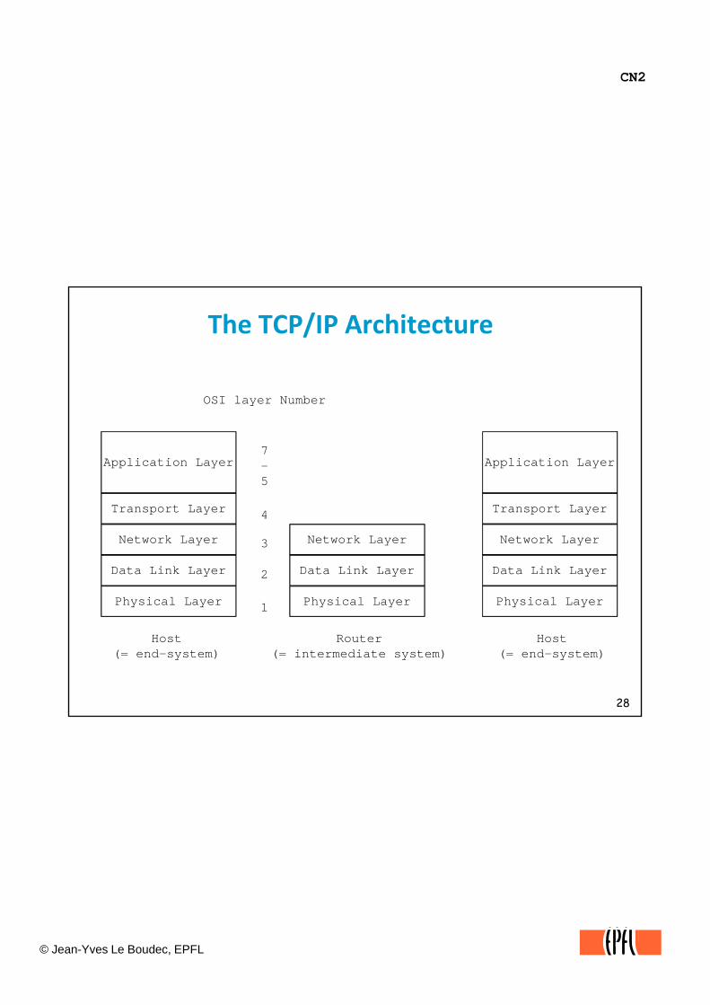
An architecture is a set of external behaviour specifications for a complete communication system. It describes protocols and services, but not how to implement them.The TCP/IP Architecture, or the Internet Architecture is described by a collection of Internet standards, published in documents called RFCs , p(Requests For Comments), available for example from ftp://ftp.switch.ch/standard.
The picture shows all the layers of the Internet Architecture. There exists, inside every layer, a number of protocols that we will discover in this course.
There exist other architectures, each of them having a different set of layers and names for layers. There are:proprietary architectures: SNA (IBM), Decnet (Digital), AppleTalk (Apple), XNS (Xerox), UUCP (Unix internal protocols), etcthe ITU architecture defines public networks for telephony, telex, fax, data networks (X.25, Frame Relay, mail and directory services) and ATMthe IEEE LAN architecture defines layers 1 and 2 for local area networks. We will see some details later. The OSI (Open Systems Interconnection) architecture is an official standard, similar to the TCP/IP architecture but is now obsolete It has 7 layers instead of 5 However the OSI model is still frequently used to
29
architecture, but is now obsolete. It has 7 layers instead of 5. However, the OSI model is still frequently used to describe systems; this is why the application layer is often called “layer 7”.
Today, the TCP/IP architecture has become dominant, so this is the only one we will study in detail. The ITU architecture (Frame Relay and ATM) does also play an important role and we will study it at the end of the course.Different architectures do not interoperate by themselves at the protocol level. For example, the OSI transport protocols are not compatible with TCP or UDP.

CN2
© Jean-Yves Le Boudec, EPFL
Test Your Understanding
Q Say what each layer of the TCP/IP architecture is doing.
solution
30
CN2
© Jean-Yves Le Boudec, EPFL
Questions
When data is transferred from a web server to a PC, TCP is runA Only in the server and the PCA. Only in the server and the PC
B. Only in the server
C. In the server, the PC and the routers in‐between if there is any
What is client ? A server ?
31
CN2
© Jean-Yves Le Boudec, EPFL
Questions
An application program normally uses TCP or UDP to send dataTrueTrue
False
What is the difference between TCP and UDP ?What is the difference between TCP and UDP ?
32
CN2
© Jean-Yves Le Boudec, EPFL
Questions
What is the difference between an IP address and a domain name ?name ?
In a IP packet there isIn a IP packet there isA. the IP address of the source
B the IP address of the destination
C the name of the destination
D the name of the source
33
CN2
© Jean-Yves Le Boudec, EPFL
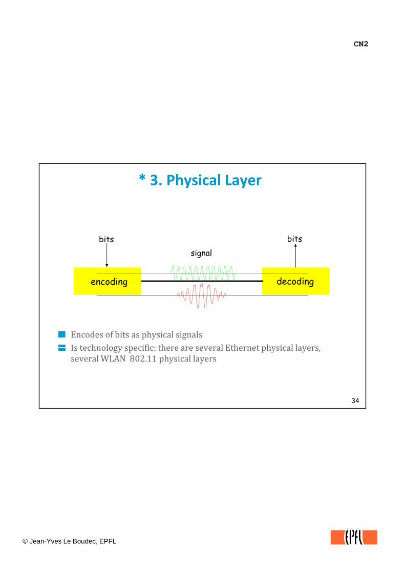
* 3. Physical Layer
bits bitssignal
encoding decoding
Encodes of bits as physical signalsIs technology specific: there are several Ethernet physical layers
g g
34
Is technology specific: there are several Ethernet physical layers, several WLAN 802.11 physical layers
CN2
© Jean-Yves Le Boudec, EPFL
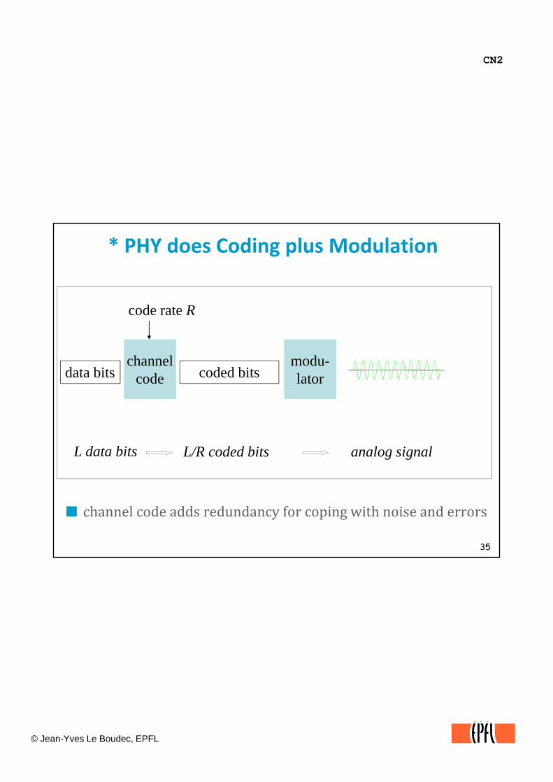
* PHY does Coding plus Modulation
d t R
data bitschannel
code coded bits
code rate R
modu-lator
L data bits L/R coded bits analog signal
35
channel code adds redundancy for coping with noise and errors
CN2
© Jean-Yves Le Boudec, EPFL
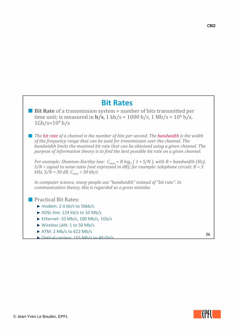
Bit RatesBit Rate of a transmission system = number of bits transmitted per time unit; is measured in b/s, 1 kb/s = 1000 b/s, 1 Mb/s = 106 b/s, 1Gb/s=109 b/s
The bit rate of a channel is the number of bits per second. The bandwidth is the width of the frequency range that can be used for transmission over the channel. The bandwidth limits the maximal bit rate that can be obtained using a given channel. The purpose of information theory is to find the best possible bit rate on a given channel.
For example: ShannonHartley law: Cmax = B log2 ( 1 + S/N ), with B = bandwidth (Hz), S/N = signal to noise ratio (not expressed in dB); for example: telephone circuit: B = 3S/N = signal to noise ratio (not expressed in dB); for example: telephone circuit: B = 3 kHz, S/N = 30 dB, Cmax = 30 kb/s
In computer science, many people use “bandwidth” instead of “bit rate”. In communication theory, this is regarded as a gross mistake.
Practical Bit Rates:
36
modem: 2.4 kb/s to 56kb/s ADSL line: 124 kb/s to 10 Mb/sEthernet: 10 Mb/s, 100 Mb/s, 1Gb/sWireless LAN: 1 to 50 Mb/sATM: 2 Mb/s to 622 Mb/sOptical carriers: 155 Mb/s to 49 Gb/s
CN2
© Jean-Yves Le Boudec, EPFL
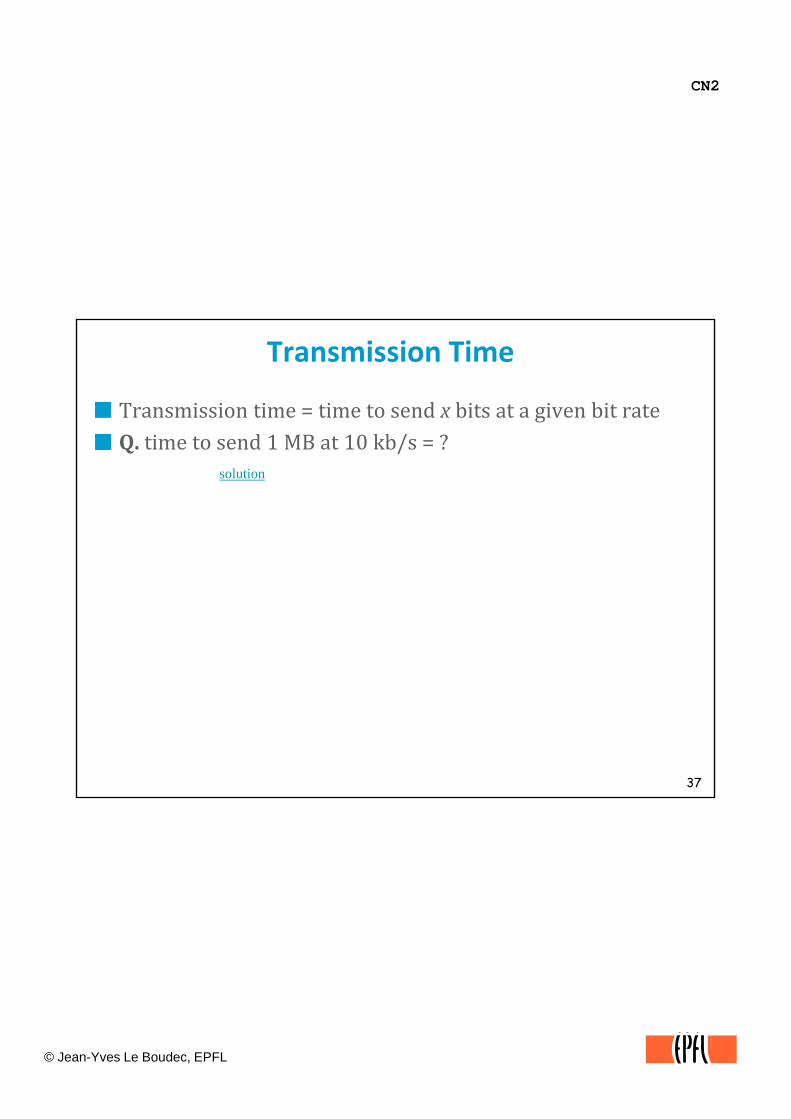
Transmission Time
Transmission time = time to send x bits at a given bit rateQ ti e to se d 1 MB at 10 kb/s ?Q. time to send 1 MB at 10 kb/s = ?
solution
37

CN2
© Jean-Yves Le Boudec, EPFL
PropagationPropagation between A and B = time for the head of signal to travel from A to B
t0 t1 tn
A time
si - ti = D (propagation delay)
D = d /c where d = distance c =signal celerity (speed of light)
s0 s1 sn
B
38
D = d /c, where d = distance, c =signal celerity (speed of light)copper: c= 2.3e+08 m/s; glass: c= 2e+08 m/s;Rule of thumb: 5 μs/km; example: earth round trip in fiber: D = 0.2 stime through circuits also adds to propagation delaysLausanne ‐ Concarneau over acoustic channel. D = ??? A.1 hour

CN2
© Jean-Yves Le Boudec, EPFL
ThroughputThroughput = number of useful data bits / time unitIt is not the same as the bit rate Why ?It is not the same as the bit rate. Why ?
protocol overhead: protocols like UDP use some bytes to transmit protocol information. This reduces the throughput. If you send onebyte messages with UDP, then for every byte you create an Ethernet packet of size 1 + 8 + 20 + 26 = 53 bytes, thus the maximum throughput you could ever get at the UDP service interface if you use a 64 kb/s channel would be 1.2 kb/s.
protocol waiting times: some protocols may force you to wait for some event, as we show on the next page.
Same units as a bit rateb/s, kb/s, Mb/s
39
CN2
© Jean-Yves Le Boudec, EPFL
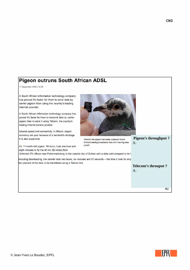
Pigeon’s throughput ?A:
40
Telecom’s throuput ?A:
CN2
© Jean-Yves Le Boudec, EPFL
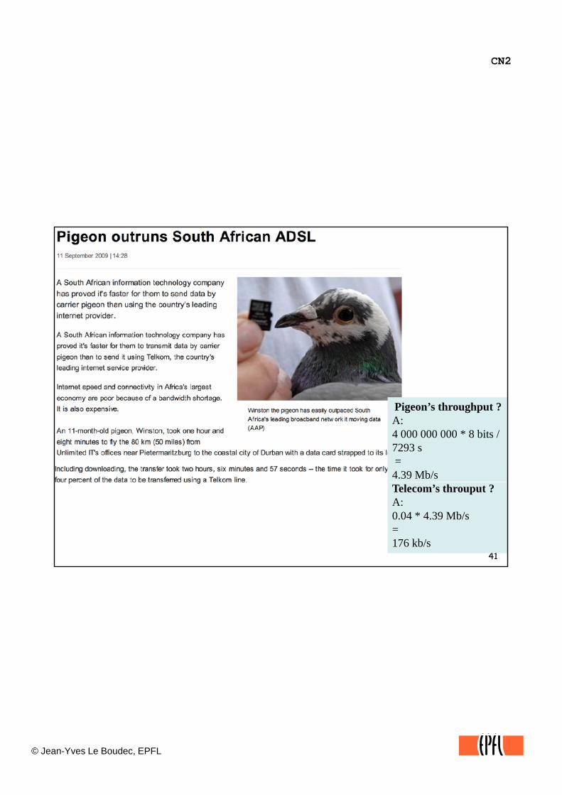
Pigeon’s throughput ?A:4 000 000 000 * 8 bits /7293 s =4.39 Mb/s
41
Telecom’s throuput ?A:0.04 * 4.39 Mb/s=176 kb/s
CN2
© Jean-Yves Le Boudec, EPFL
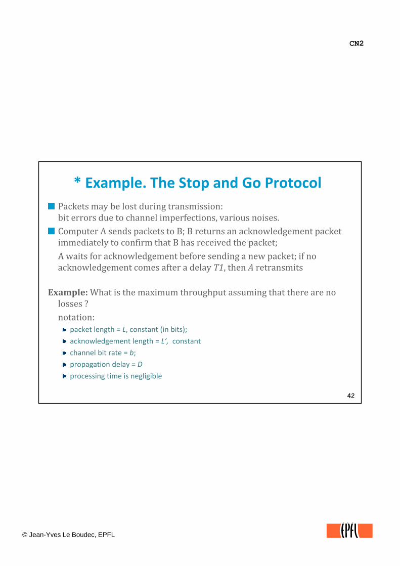
* Example. The Stop and Go ProtocolPackets may be lost during transmission:bit errors due to channel imperfections, various noises.pComputer A sends packets to B; B returns an acknowledgement packet immediately to confirm that B has received the packet;A waits for acknowledgement before sending a new packet; if no acknowledgement comes after a delay T1, then A retransmits
Example: What is the maximum throughput assuming that there are no losses ?notation:
packet length = L, constant (in bits);
acknowledgement length = L’, constant
42
acknowledgement length L , constant
channel bit rate = b;
propagation delay = D
processing time is negligible

CN2
© Jean-Yves Le Boudec, EPFL
* Solution: The Stop and Go Protocolpacket P1 sent packet P1 acknowledgedT =L/D 2D T’=L’/b
A
time
A
B
overhead
43« bandwidth »-delay product
CN2
© Jean-Yves Le Boudec, EPFL
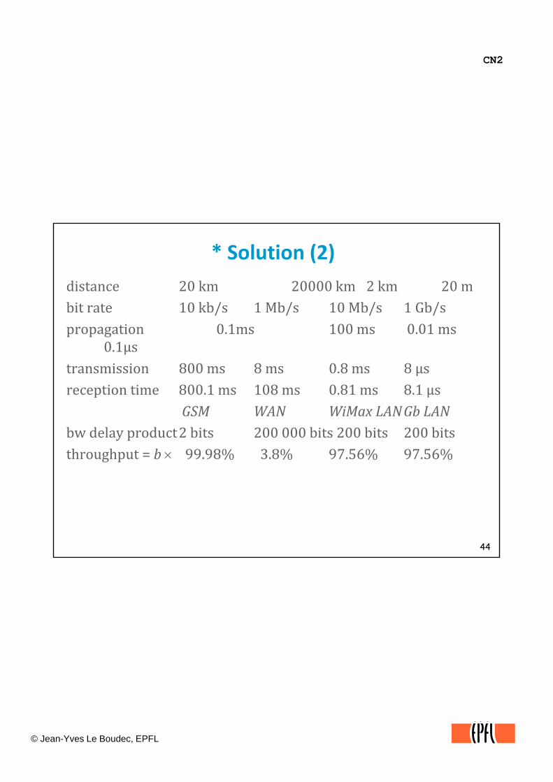
* Solution (2)distance 20 km 20000 km 2 km 20 mbit rate 10 kb/s 1 Mb/s 10 Mb/s 1 Gb/sbit rate 10 kb/s 1 Mb/s 10 Mb/s 1 Gb/spropagation 0.1ms 100 ms 0.01 ms
0.1µstransmission 800 ms 8 ms 0.8 ms 8 µsreception time 800 1ms 108 ms 0 81ms 8 1 µsreception time 800.1 ms 108 ms 0.81 ms 8.1 µs
GSM WAN WiMax LANGb LANbw delay product2 bits 200 000 bits 200 bits 200 bitsthroughput = b × 99.98% 3.8% 97.56% 97.56%
44
CN2
© Jean-Yves Le Boudec, EPFL
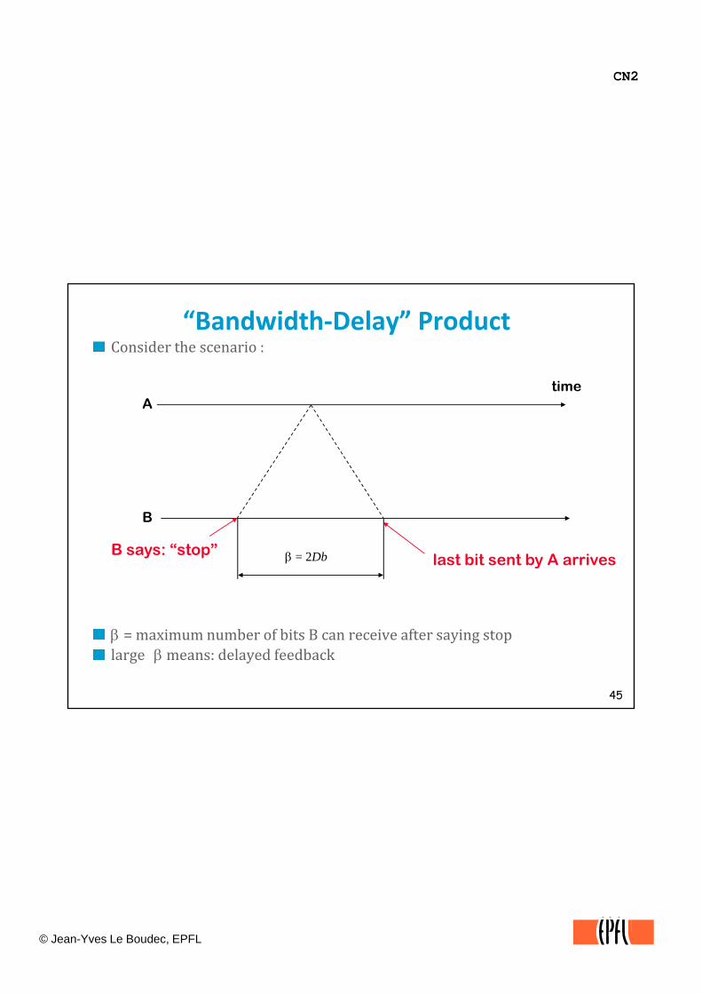
“Bandwidth‐Delay” ProductConsider the scenario :
timeA
time
B
B says: “stop”last bit sent by A arrivesβ = 2Db
45
β = maximum number of bits B can receive after saying stoplarge βmeans: delayed feedback
CN2
© Jean-Yves Le Boudec, EPFL
Test Your Understanding
Q. Does packet switching reduce propagation or transmission delay ?transmission delay ?
Q. If transmission is one hop only, is there any benefit to breaking a large data file into smaller blocks (called «packets ») ?
46
CN2
© Jean-Yves Le Boudec, EPFL
Questions
When a program passes data to a UDP socket, can we say that this data isthis data is
A PDU ?
An SDU ?
What is the common name for an IP PDU ?
An Ethernet PDU ?
A TCP PDU ?
A UDP PDU ?
47

CN2
© Jean-Yves Le Boudec, EPFL
Facts to Remember (this document)Computer networks are organized using a layered modelThere is one layered model per architectureThere is one layered model per architecture
ex. TCP/IP, Appletalk, Novell Netware, OSI
The transport layer of TCP/IP provides a programming interface to the application layer. It exists in two forms: UDP (unreliable, datagram) and TCP (reliable, stream) .g ) ( )Know the difference between propagation and transmission times.
48
CN2
© Jean-Yves Le Boudec, EPFL
Solutions
49
CN2
© Jean-Yves Le Boudec, EPFL
*Test Your Understanding
Q Say what each layer of the TCP/IP architecture is doing.A A.
Layer 1 = PHY transmits bits on cables or over adio waves in the air or in free space
Layer 2 = MAC allows several systems to use the same cable or radio waves
Layer 3 = network layer interconnects all systems; has mainly intermediate systemssystems.
Layer 4 = transport provides a programming interface to the application
Layer 5 = application (also called layer 7 in OSI model ) provides applications that allow people and machines to communicate.
50
back
CN2
© Jean-Yves Le Boudec, EPFL
*Transmission Time
Transmission time = time to send x bits at a given bit rateQ ti e to se d 1 MB at 10 kb/s ?Q. time to send 1 MB at 10 kb/s = ?A. 8 × 106 bits / 104 b/s = 800 s
back
51
CN2
© Jean-Yves Le Boudec, EPFL
*Test Your Understanding
Q. Does packet switching reduce propagation or transmission delay ?delay ?A. transmission, in multihop scenarioQ. If transmission is one hop only, is there any benefit to breaking a large data file into smaller blocks (called «packets ») ?A.
not from a delay view point
but because of bit errors on the channel, it is likely that a very large block is not correct, splitting and retransmitting only the incorrect blocks may be better
52
practical buffer sizes may be an issue
back