the synthesis and electrocatalytic activities of mos2 for...
TRANSCRIPT
The Synthesis and Electrocatalytic Activities
of Molybdenum Sulfide for Hydrogen
Evolution Reaction
Thesis by
Zhengxing Li
In Partial Fulfillment of the Requirements
For the Degree of
Master of Science
King Abdullah University of Science and Technology
Thuwal, Kingdom of Saudi Arabia
July, 2014
2
EXAMINATION COMMITTEE APPROVALS FORM
This thesis of Zhengxing Li is approved by the examination committee
Committee Chairperson: Prof. Dr. Yu Han
Committee Co-Chair: Prof. Dr. Niveen M. Khashab
Committee Member: Prof. Dr. Tom (Tao) Wu

3
COPYRIGHT © July 2014
Zhengxing Li
All Rights Reserved
4
ABSTRACT
In the context of the future hydrogen economy, effective production of hydrogen (H2)
from readily available and sustainable resources is of crucial importance. Hydrogen
generation via water splitting by solar energy or electricity has attracted great attention in
recent years. In comparison with photocatalytic water-splitting directly using solar light,
which is ideal but the relevant technologies are not yet mature, electrolysis of water with
catalyst is more practical at the current stage. The Pt-group noble metals are the most
effective electrocatalysts for hydrogen evolution reaction (HER) from water, but their
high costs limit their applications.
Due to the earth-abundance and low price, MoS2 is expected to be a good alternative of
the Pt-group metals for HER. Plenty of researches have been conducted for improving
the HER activities of MoS2 by optimizing its synthesis method. However, it remains
challenging to prepare MoS2 catalysts with high and controllable activity, and more
investigations are still needed to better understand the structure-performance correlation
in this system.
In this thesis, we report a new strategy for fabricating MoS2 eletrocatalysts which gives
rise to much improved HER performance and allows us to tune the electrocatalytic
activity by varying the preparation conditions. Specifically, we sulfurized molybdenum
oxide on the surface of a Ti foil electrode via a facile chemical vapor deposition (CVD)
method, and directly used the electrode for HER testing. Depending on the CVD
temperature, the MoO2-MoS2 nanocomposites show different HER activities. Under the
5
optimal synthesis condition (400ºC), the resulting catalyst exhibited excellent HER
activity: an onset potential (overpotential) of 0.095 V versus RHE and the Tafel slope of
40 mv/dec. Such a performance exceeds those of most reported MoS2 based HER
electrocatalysts. We demonstrated that the CVD temperature has significant influence on
the catalysts in crystallinity degree, particle size and dispersion, morphology, and density
of the edge sites etc., and these factors in turn determine the HER activity.

6
ACKNOWLEDGMENTS
I would like to express my great thanks and sincerest appreciations to my supervisor
Professor Dr. Yu Han for his tremendous guidance and supports during my stay in
KAUST for the master degree. Professor Dr. Yu Han has given me huge assistance in the
designing of the research projects and the problems solving in the experiments. I am so
grateful that he has supplied me numerous opportunities to have the access to the
advanced facilities, which is of great help for the research. Professor Dr. Yu Han’s
outstanding personality and wisdom has generated so big influences on me that it will be
greatly beneficial to me for the future life.
I am also grateful to my committee members, Prof. Dr. Niveen M. Khashab and Prof. Dr.
Tao (Tom) Wu for serving as my committee members even at the summer break. Thank
you for your brilliant comments and thought-provoking suggestions, many thanks to you.
I would also like thank the Professors and Doctors in the core lab: Dr. Lan Zhao, Dr.
Qingxiao Wang, Dr. Liang Li, Dr. Yang Yang, Dr. Dalaver H. Anjum etc. Under their
guidance, I have been familiar with most of the advanced facilities in the university. They
are so kind and friendly to me, especially Dr. Lan Zhao and Dr. Qingxiao Wang.
As well, I am so thankful to the postdocs and students in the lab, Dr. Yihan Zhu has given
me plenty of help in the research, especially the calculation research and the analysis of
the XRD and HRTEM. And Dr. Kexin Yao has also given me a lot of guidance, such as
the using of the electrochemistry workstation and CVD furnace etc. Also, Dr. Jiangfeng
Huang, Dr. Tong Zhang, Dr. Xiaohua Ma, Dr. Zhaohui Liu, Dr. Jiezhe Zhang and Dr.

7
Qiwei Tian have assisted me a lot in the daily life and supplied me an enjoyable life in
the lab.
Thanks should also be given to my best friends in KAUST, Dr. Weili Yu, Dr. Shuo Liu,
Dr. Miss. Yanghui Xiong, Mr. Yu Peng, Mrs. Maolida Aihemaiti, Mrs. Dunya Abudu,
Mr.Yangqing Gao, Mr. Zhenbang Liu, Mr. Peng Zhan etc. These guys have created a
beautiful life and happy life without loneliness for me in KAUST.
As well, I am much appreciated to my advisor Professor Dr. Zhong Zhang in Chinese
Academy of Sciences for his generous assistants and supports in my study in Saudi
Arabia.
Acknowledge should also be given to KAUST and Chinese Academy of Sciences for
providing the dual degree studying in Saudi Arabia and China.
Finanlly, I would like to devote my deepest thanks and gratitude to my family for their
selfless support throughout my life. In particular, my parents, who are the real source of
inspiration in my life, will give me the inner strength to overcome the hardships in the
life, when I am in the bad situation. I am also grateful to my sister for her continuous
guidance since my childhood.
All best wishes to my professors, friends, relatives and families.

8
TABLE OF CONTENTS
EXAMINATION COMMITTEE APPROVALS FORM ............................................. 2
ABSTRACT ....................................................................................................................... 4
ACKNOWLEDGMENTS ................................................................................................ 6
TABLE OF CONTENTS ................................................................................................. 8
LIST OF ABBREVIATIONS ........................................................................................ 10
LIST OF FIGURES ........................................................................................................ 11
LIST OF TABLES .......................................................................................................... 13
1. INTRODUCTION..................................................................................................... 14
1.1 Energy Technologies ..................................................................................... 14
1.1.1 Energy Sources ......................................................................................... 14
1.2 Hydrogen Energy........................................................................................... 15
1.2.1 Hydrogen Energy Carrier .......................................................................... 15
1.2.2 Hydrogen Production ................................................................................ 16
1.3 Hydrogen Evolution Catalysts...................................................................... 18
1.3.1 Pt Group Electrocatalysts ........................................................................... 18
1.3.2 Few Layered Electrocatalytic Activity Materials ...................................... 19
2. EXPERIMENTS ...................................................................................................... 27
2.1 The Electrocatalytic Activities of MoS2 Synthesized by the CVD Method for
HER .......................................................................................................................... 27
2.1.1 The Synthesis of the MoS2 via the CVD Method ....................................... 27
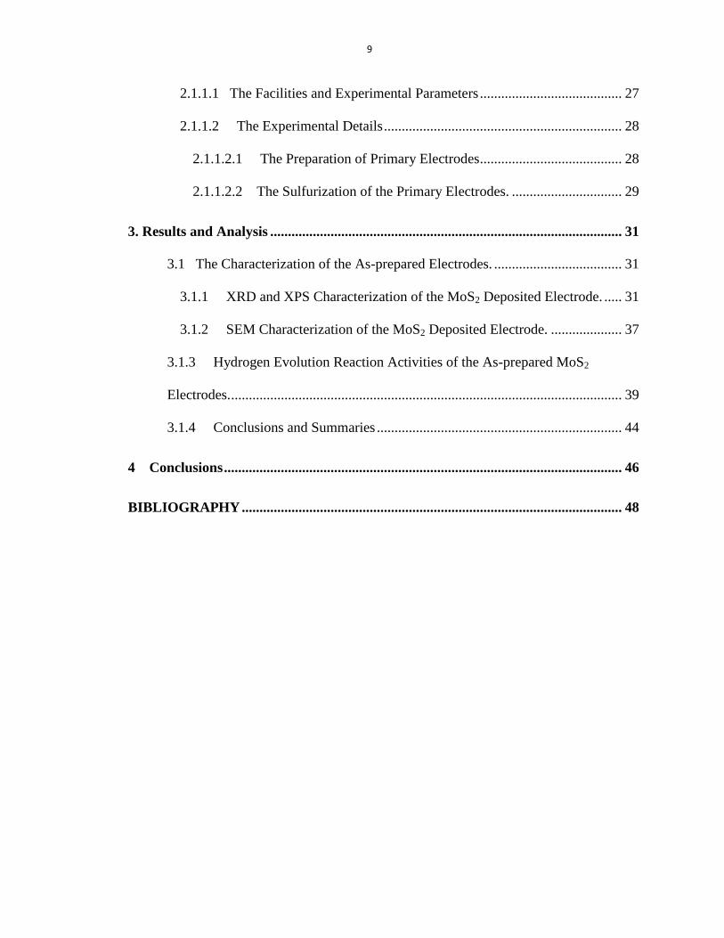
9
2.1.1.1 The Facilities and Experimental Parameters ........................................ 27
2.1.1.2 The Experimental Details ................................................................... 28
2.1.1.2.1 The Preparation of Primary Electrodes........................................ 28
2.1.1.2.2 The Sulfurization of the Primary Electrodes. ............................... 29
3. Results and Analysis ................................................................................................... 31
3.1 The Characterization of the As-prepared Electrodes. .................................... 31
3.1.1 XRD and XPS Characterization of the MoS2 Deposited Electrode. ..... 31
3.1.2 SEM Characterization of the MoS2 Deposited Electrode. .................... 37
3.1.3 Hydrogen Evolution Reaction Activities of the As-prepared MoS2
Electrodes. .............................................................................................................. 39
3.1.4 Conclusions and Summaries ..................................................................... 44
4 Conclusions ................................................................................................................ 46
BIBLIOGRAPHY ........................................................................................................... 48
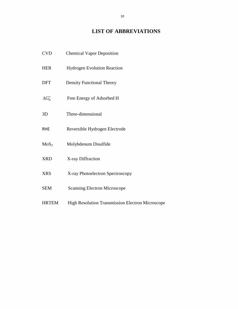
10
LIST OF ABBREVIATIONS
CVD Chemical Vapor Deposition
HER Hydrogen Evolution Reaction
DFT Density Functional Theory
G
Free Energy of Adsorbed H
3D Three-dimensional
RHE Reversible Hydrogen Electrode
MoS2 Molybdenum Disulfide
XRD X-ray Diffraction
XRS X-ray Photoelectron Spectroscopy
SEM Scanning Electron Microscope
HRTEM High Resolution Transmission Electron Microscope
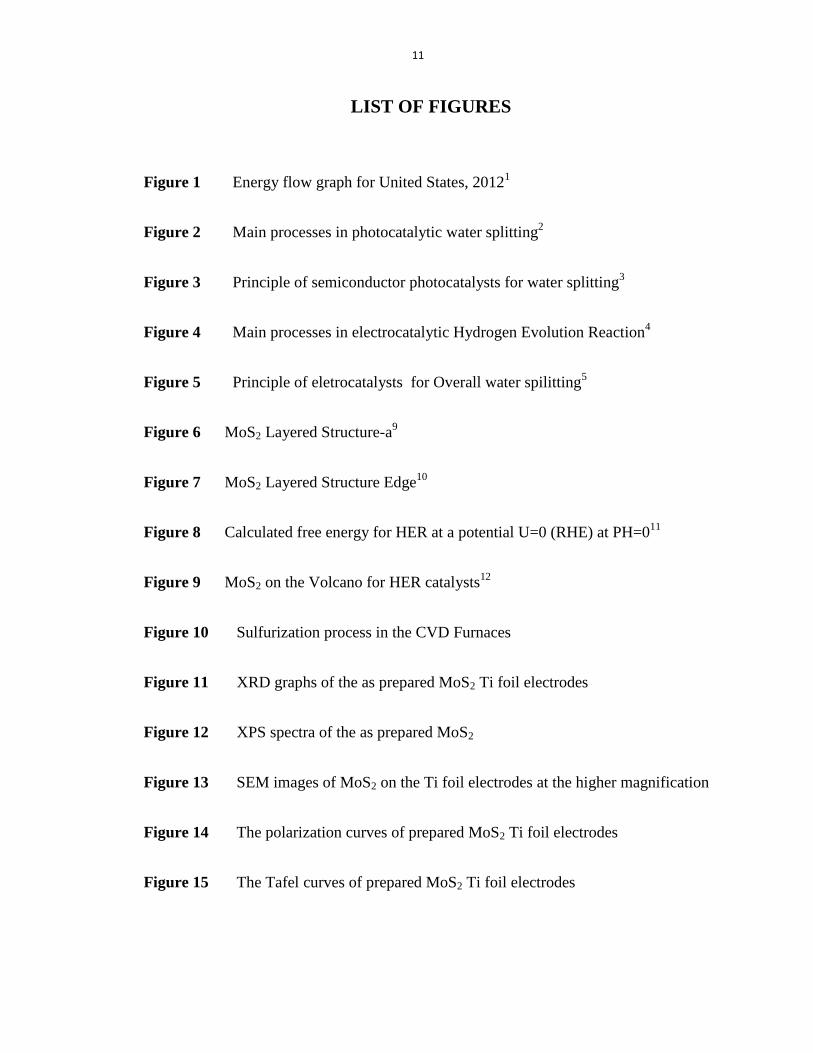
11
LIST OF FIGURES
Figure 1 Energy flow graph for United States, 20121
Figure 2 Main processes in photocatalytic water splitting2
Figure 3 Principle of semiconductor photocatalysts for water splitting3
Figure 4 Main processes in electrocatalytic Hydrogen Evolution Reaction4
Figure 5 Principle of eletrocatalysts for Overall water spilitting5
Figure 6 MoS2 Layered Structure-a9
Figure 7 MoS2 Layered Structure Edge10
Figure 8 Calculated free energy for HER at a potential U=0 (RHE) at PH=011
Figure 9 MoS2 on the Volcano for HER catalysts12
Figure 10 Sulfurization process in the CVD Furnaces
Figure 11 XRD graphs of the as prepared MoS2 Ti foil electrodes
Figure 12 XPS spectra of the as prepared MoS2
Figure 13 SEM images of MoS2 on the Ti foil electrodes at the higher magnification
Figure 14 The polarization curves of prepared MoS2 Ti foil electrodes
Figure 15 The Tafel curves of prepared MoS2 Ti foil electrodes

12
Figure 16 The polarization curves of Ti electrodes (after sulfurization), MoS2@400˚C
Ti foils electrodes and commercial Pt electrode
13
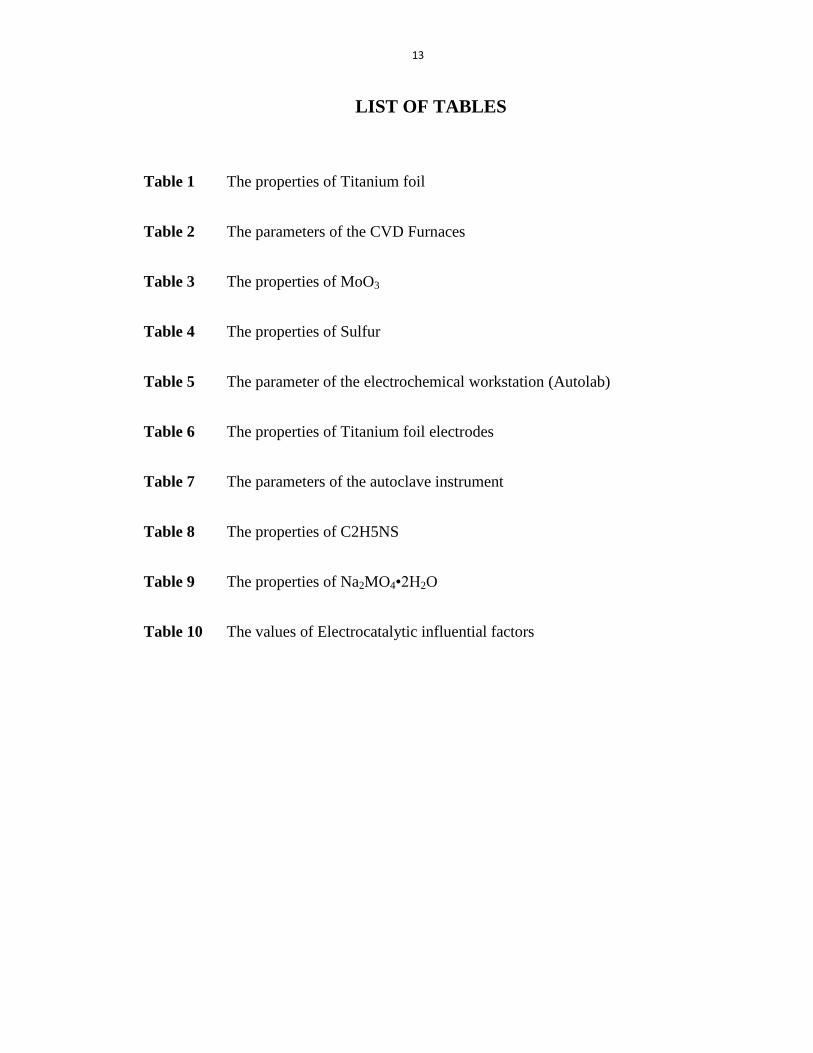
LIST OF TABLES
Table 1 The properties of Titanium foil
Table 2 The parameters of the CVD Furnaces
Table 3 The properties of MoO3
Table 4 The properties of Sulfur
Table 5 The parameter of the electrochemical workstation (Autolab)
Table 6 The properties of Titanium foil electrodes
Table 7 The parameters of the autoclave instrument
Table 8 The properties of C2H5NS
Table 9 The properties of Na2MO4•2H2O
Table 10 The values of Electrocatalytic influential factors

14
1. INTRODUCTION
1.1 Energy Technologies
1.1.1 Energy Sources
With the high-speed development of the society, the supply of energy has becoming more
and more important for the daily life of the human beings. People’s lifestyles have a huge
demanding of energy, as the transportations, daily comforts and properties would lose its
colors without the energy supply.1 So the security of the energy is vital for sustainable
development of the society, we could not take it for granted. Normally, the energy
sources could be divided into five broad categories: Coal, Natural gas, Petroleum,
Nuclear and Renewable energies (Figure 1)18
, the Coal, Natural gas, Petroleum are called
fossil fuels and the Renewables include Wind, Biofuels, Wood, Geothermal, Solar energy,
Hydrogen power etc..19
Each source of the energy has some drawbacks and disadvantages. The fossil fuels are
the main sources for the energy consumptions, but their rapid depletion has generated
enormous problems, such as the greenhouse effect and the contaminations, in particular
the air pollutions. The Nuclear energy could produce the radioactive fission productions,
which is harmful to the mankind health. And also the solar energies are limited to the
geography and the large space.1, 20
However, compared with the fossil fuels and nuclear energies, most of the renewable
energies have plenty of advantages, such as, Cleanliness, abundance and Environmental
friendliness, in particular, the Hydrogen energy, which is the most environmental friendly
fuel and has the highest energy density21
. Thus, sustainable hydrogen production has been

15
becoming increasingly important for solving the energy crisis and environmental issues
and gotten the great attention. 20, 22
Figure 1: Energy flow graph for United States, 20121
1.2 Hydrogen Energy
1.2.1 Hydrogen Energy Carrier
Hydrogen is of the highest mass energy density, which is of course larger than any other
fuel all over the world. The hydrogen burning reaction could be described as the
following:
2H2 (g) + O2 (g) → 2H2O (l) (ΔH= -286.0 kJ/mol) …………………………… ①
The formula has the meaning that we could get 286kJ energy from the 1mol reaction of
the hydrogen and the oxygen. Thus, it could be easily seen from the formula that the mass
hydrogen energy density is 143.0 kJ/g (E = 286.0 kJ/mol × 0.5 mol/g), exhibiting the

16
largest energy density value comparing with all the other fuels23
. Based on properties of
the higher energy density and the lower weight, hydrogen (mainly the liquid hydrogen)
has been used in many areas, especially the transportations and space technologies.21, 24
1.2.2 Hydrogen Production
As an ideal energy carrier, the clean and renewable hydrogen could be created efficiently
and cost-effectively by two ways:
(1) In industry, the hydrogen could be produced by the steam reforming of natural gas
(CH4), which is shown as the follows:
CH4(g) + H2O(g) → CO(g) + 3H2(g) ………………………………… ②
Nowadays, 95% of the standard production for the hydrogen in the United States is
produced by the reforming of natural gas in the large central plants, which is a procedure
that would generate numerous releases of carbon dioxide, and even carbon monoxide,
although not as much as the outright burning of the natural gas. Though this method is a
vital route for large amount of hydrogen production, the consumption of the fossil fuels
could not be avoided. 25
(2) Another pathway to produce the hydrogen is to conduct the water splitting. The water
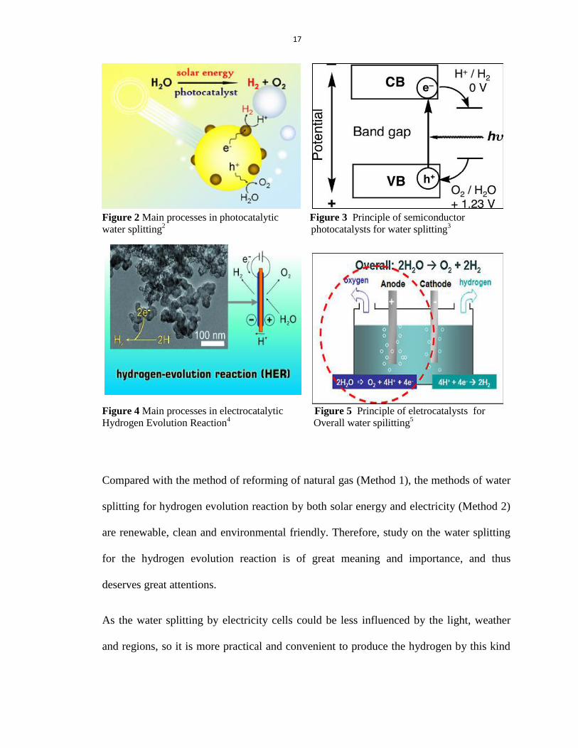
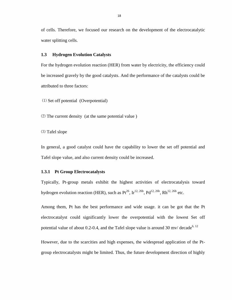
splitting cells for hydrogen evolution reaction can be divided into two categories: (i)
Solar water splitting cells by solar energy (Figure 2 & 3); (ii) Electrocatalytic water
(3) plitting cells by electricity (Figure 4 & 5).
17
Figure 2 Main processes in photocatalytic Figure 3 Principle of semiconductor
water splitting2 photocatalysts for water splitting
3
Figure 4 Main processes in electrocatalytic Figure 5 Principle of eletrocatalysts for
Hydrogen Evolution Reaction4 Overall water spilitting
5
Compared with the method of reforming of natural gas (Method 1), the methods of water
splitting for hydrogen evolution reaction by both solar energy and electricity (Method 2)
are renewable, clean and environmental friendly. Therefore, study on the water splitting
for the hydrogen evolution reaction is of great meaning and importance, and thus
deserves great attentions.
As the water splitting by electricity cells could be less influenced by the light, weather
and regions, so it is more practical and convenient to produce the hydrogen by this kind
18
of cells. Therefore, we focused our research on the development of the electrocatalytic
water splitting cells.
1.3 Hydrogen Evolution Catalysts
For the hydrogen evolution reaction (HER) from water by electricity, the efficiency could
be increased gravely by the good catalysts. And the performance of the catalysts could be
attributed to three factors:
⑴ Set off potential (Overpotential)
⑵ The current density (at the same potential value )
⑶ Tafel slope
In general, a good catalyst could have the capability to lower the set off potential and
Tafel slope value, and also current density could be increased.
1.3.1 Pt Group Electrocatalysts
Typically, Pt-group metals exhibit the highest activities of electrocatalysis toward
hydrogen evolution reaction (HER), such as Pt26
, Ir12, 26b
, Pd12, 26b
, Rh12, 26b
etc.
Among them, Pt has the best performance and wide usage. it can be got that the Pt
electrocatalyst could significantly lower the overpotential with the lowest Set off
potential value of about 0.2-0.4, and the Tafel slope value is around 30 mv/ decade6, 12
However, due to the scarcities and high expenses, the widespread application of the Pt-
group electrocatalysts might be limited. Thus, the future development direction of highly

19
activity electrocatalysts for HER is focused on the materials which are cheap and earth-
abundant22b
.
1.3.2 Few Layered Electrocatalytic Activity Materials
In recent years, two-dimensional (2D) layered materials have attracted considerable
attention in both the fundamental and application science, because of their unique
chemical and physical properties17, 27
. The layered bulk materials are formed by the
stacking of planes via weak interlayer van der Waals interactions.28
Due to their
anisotropic structure, the ultrathin flakes can be obtained by chemical or mechanical
processes, as well as the thin films, nanosheets, nanoribbons, nanoparticles and nanotubes
etc.17, 28
MoS2 is a brilliant star in the 2D layered materials’ group, which is a silvery black solid
that occurs as the cheap and earth-abundant mineral molybdenite 7-8
For the buck MoS2, each Mo is being connected to the nearest six sulfide atoms, by
occupying the center of the sphere with trigonal prismatic coordination. And each sulfur
atom is bound to three Mo centers, with a pyramidal shape. 9 29
In this way, the bulk MoS2 of the layered structures is formed by the interconnection of
trigonal prisms. And so, the sulfide atoms layers are interacted by the weak van der
Waals force. 9

20
Figure 6 MoS2 Layered Structure-a9 Figure 7 MoS2 Layered Structure Edge
10
Based on the special layered structure and stable properties of MoS2, which is an
relatively unreactive material, being unaffected by dilute acid, alkali, organic solvent,
plenty of applications have been put into practice.
(1) Lubricant
Because of the interactions of the near sulfide atoms layers conducted by the weak van
der Waals force, MoS2 has the properties of lubricants, due to the low coefficient of
friction. In general, MoS2 is commonly used as a dry lubricant with particle sizes range
from 1 µm to100 µm. Likewise, some other layered materials, such as graphite,
hexagonal boron nitride etc., exhibit the similar lubricating properties.30
(2) Petroleum refining
MoS2 is commonly well known as a good catalyst for hydrodesulfurization reaction to
conduct the desulfurization in petroleum refineries.31
Recently, Smith etc.32
have made
the exfoliated MoS2,which gave the better performance for the reaction. And also, the
effectiveness of the MoS2 catalysts has already enhanced by doping with small amounts

21
of cobalt or nickel and the intimate mixture is supported on alumina33
, which made the
MoS2 application on industry benefit the mankind a lot.
(3) Electronic and optical properties
People found that the properties of single or few layer MoS2 is different from the bulk
MoS2, in particular the Electronic and optical properties. Whereas the band gap of Bulk
MoS2 is1.2 eV, the band gap of single layers Mos2 is 1.8 eV.34 , which make it possible
for the production of sensitive photodetectors35
and the switchable transistors9.
The recent studies of MoS2 have shown that it is one of the best electrocatalysts for the
Hydrogen Evolution Reactions, and both the calculations and the experimental results
have given the certificates that MoS2 might be the most promising alternatives of
platinum. 14, 17
The electrocatalytic property of molybdenum sulfides for the hydrogen evolution
reactions could stem from 1970s.36
In the year of 1977, Tributsch, H first reported the
electrochemical performance of molybdenum sulfides layer crystals.36
However, the bulk
molybdenum sulfides had the lower electrocatalytic activities, thus few attentions had
been attracted on this research topic, so the research progress is very slow during the past
decades.37
In 2005, Berit etc. conducted the biomimetic electrocatalytic hydrogen evolution process
of the Hydrogenase and Nitrogenase by using density functional theory (DFT)
calculations 11
, they reported that G
(free energy of adsorbed H) is a good indicator of
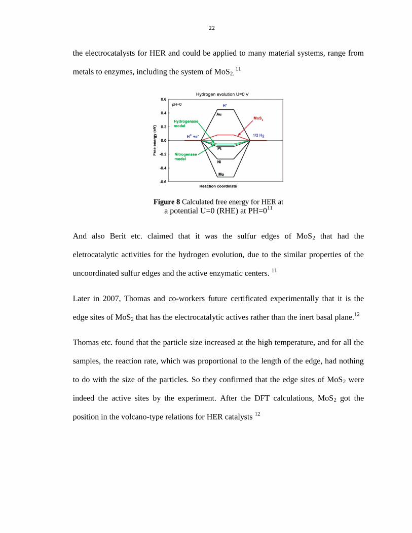
22
the electrocatalysts for HER and could be applied to many material systems, range from
metals to enzymes, including the system of MoS2. 11
Figure 8 Calculated free energy for HER at a potential U=0 (RHE) at PH=0
11
And also Berit etc. claimed that it was the sulfur edges of MoS2 that had the
eletrocatalytic activities for the hydrogen evolution, due to the similar properties of the
uncoordinated sulfur edges and the active enzymatic centers. 11
Later in 2007, Thomas and co-workers future certificated experimentally that it is the
edge sites of MoS2 that has the electrocatalytic actives rather than the inert basal plane.12
Thomas etc. found that the particle size increased at the high temperature, and for all the
samples, the reaction rate, which was proportional to the length of the edge, had nothing
to do with the size of the particles. So they confirmed that the edge sites of MoS2 were
indeed the active sites by the experiment. After the DFT calculations, MoS2 got the
position in the volcano-type relations for HER catalysts 12
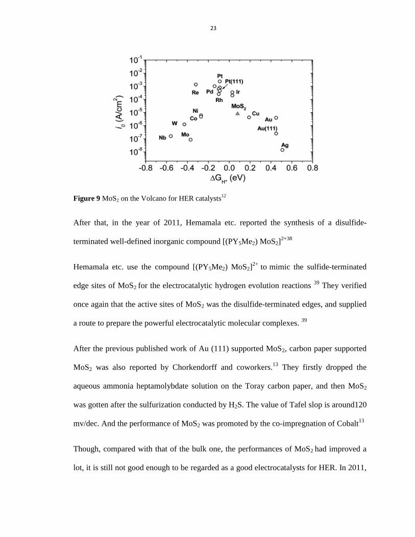
23
Figure 9 MoS2 on the Volcano for HER catalysts12
After that, in the year of 2011, Hemamala etc. reported the synthesis of a disulfide-
terminated well-defined inorganic compound [(PY5Me2) MoS2]2+38
Hemamala etc. use the compound [(PY5Me2) MoS2]2+
to mimic the sulfide-terminated
edge sites of MoS2 for the electrocatalytic hydrogen evolution reactions 39
They verified
once again that the active sites of MoS2 was the disulfide-terminated edges, and supplied
a route to prepare the powerful electrocatalytic molecular complexes. 39
After the previous published work of Au (111) supported MoS2, carbon paper supported
MoS2 was also reported by Chorkendorff and coworkers.13
They firstly dropped the
aqueous ammonia heptamolybdate solution on the Toray carbon paper, and then MoS2
was gotten after the sulfurization conducted by H2S. The value of Tafel slop is around120
mv/dec. And the performance of MoS2 was promoted by the co-impregnation of Cobalt13
Though, compared with that of the bulk one, the performances of MoS2 had improved a
lot, it is still not good enough to be regarded as a good electrocatalysts for HER. In 2011,
24
Dai etc. reported a solvothermal approach for the synthesis of MoS2/Graphene hybrids.
The MoS2/RGO hybrids were synthesized by the excellent coupling of MoS2 nano
particles on the Gaphene sheets via a facile solvothermal method. The as prepared
catalysts of MoS2/RGO hybrids exhibited great electrocatalytic activities for the
hydrogen evolution reaction with the low value of the setoff potential (~ 0.1 V) and Tafel
slope (41mv/dec).14
Later the hybrids of MoSx with CNTs and other mesoporous carbons
etc. were prepared for the hydrogen evolution reactions. 40
In 2013, Li and co-workers prepared the three-dimensional (3D) MoSx foams. They
firstly synthesized the 3D-Graphene foam on the 3D-Ni foam skeleton via chemical
vapor deposition (CVD), and then the foams were immersed in the (NH4)2MoS4 solution;
after the MoSx layers were formed on the surface of 3D-Gaphene foams by the reduction
by the Hydrogen via the CVD method, the 3D-MoSx@graphene foams electrode were
formed. These kinds of foams could load more MoSx catalysts and have the excellent
performance for the hydrogen evolution. And also they reported that the 3D
MoSx@Graphene electrode had the highest electrocatalytic activities for the hydrogen
evolution at the temperature of 120 ºC with the Tafel slop around 43 mv/dec.15
In order to get more exposed active edge sites of MoS2 for improving the efficiency for
the hydrogen evolution reactions, Thomas Jaramillo etc. reported a method to control the
surface structure of MoS2.16
They firstly deposited the Molybdenum on the silica template by the electro-deposition.
And the DG morphology MoS2 was formed by the sulphidization with H2S, followed by
the etching of silica template with 2% HF. It could be seen that the surface area, HER

25
performance and active sites were gravely improved by the engineering mesoporous
MoS2 films with DG morphology. 16
Another route to improve the performance of the MoS2 electrocatalyst for the HER is to
make the MoS2 into small particles or few layers (or single layers) to get more exposed
active edge sites. Li and coworkers enhanced the eletrcocatalytic activities of MoS2 for
hydrogen evolution reaction by the ultrasonication of the bulk MoS2.17
The diameter of
the as-prepared MoS2 nanoparticles was around 1.5 nm. And the test electrode was
fabricated in two ways: ①the assembling of as-prepared MoS2 nanoparticles on the Au
electrode. ② the drop-casting of as-prepared MoS2 nanoparticles on the Au electrode.
And they found that the assembling ones had the better performances.17
Recently, there have been papers reported that the layers of the molybdenum sulfides
have the influence on their efficiency for the hydrogen evolution reactions. The few layer
or single layer molybdenum sulfides have the better performance on HER.41
From the above, it could be seen that many efforts have been taken to obtain the higher
electrocatlytic activity MoS2 catalyst for HER from both calculations and experiments,
and it has also certificated that it is the sulfur edges of the plates rather than the inert
basal planes of MoS2 which are the active catalytical sites of MoS2 for HER, and the
conductivity that have the great influence on the performance of the MoS2 catalyst.
In the past years, many researches have been conducted to improve the imposed edges
and conductivity of MoS2. Some of them took the attention on the engineering of the
surface structures of MoS216
and the different synthesizing methods to MoS2 (PVD or
CVD12-13, 15
& Hydrothermal or solvothermal14, 40
etc.); and some researches focused on

26
the growing of MoS2 on a variety of good conductive supported substrates, such as gold12
,
graphite11
, carbon black15
, carbon paper13
, glassy carbon14, 28
, CNTs40e
and graphene14
etc.
However, up to now, the efficiency of the MoS2 elctrocatalysts is not good enough and
there are currently no ideal ways to get the MoS2 elctrocatalysts in the large amount
under the low costs. So during my studying in the period of Master Degree, my main
tasks were to make the development of the MoS2 eletrocatalysts, and finally we succeed
in finding the ways to solve the problems facing the MoS2 eletrocatalysts and improved
the performance of MoS2 eletrocatalysts for the hydrogen evolution reactions.
The researches are mainly about the synthesis of the MoS2 via the CVD method with the
low price materials.
There are many advantages for this method: ① the synthesizing materials are sulfur and
MoO3, which are easy to obtain and abundant in the earth; ② the preparing process is
very easy and the catalysts could be produced in large amount; ③ the efficiency is
excellent.
27
2. EXPERIMENTS
2.1 The Electrocatalytic Activities of MoS2 Synthesized by the CVD Method for
HER
2.1.1 The Synthesis of the MoS2 via the CVD Method
2.1.1.1 The Facilities and Experimental Parameters
The Electrode Parameter
Titanium foils (Ti)
Thickness 0.25 mm
Assay 99.99% trace metals basis
Form Foil
Products SIGMA-ALDRICH
Table 1 The properties of Titanium foil
1 •Model NBD-O1200-80IIC
2 • Limiting Temperature 1400℃
3 • Chamber size Φ80×1000mm
4 •Temperature Zone double zone
5 •Accuracy ± 1˚C
6 •Heating rate 20℃ /Min
7 •Flowing gas Argon
8 •Flowing rate 15 sccm
9 •Company products Nobody Material Science and Technology
Co., Ltd (NBD)
Table 2 The parameters of the CVD Furnaces
28
The reagents parameters
Molybdenum (VI) oxide (MoO3)
Grade ACS reagent
Assay ≥99.5%
Form Powder
Products SIGMA-ALDRICH
Table 3 The properties of MoO3
Sulfur (S)
Grade Purum p.a.
Assay ≥99.5%
Form Powder
Products SIGMA-ALDRICH
Table 4 The properties of Sulfur
2.1.1.2 The Experimental Details
2.1.1.2.1 The Preparation of Primary Electrodes
The primary Ti electrodes were prepared by the tiny Titanium foils with the appearance
size 3 mm (width) × 15 mm (long) × 0.25 mm (thickness). We firstly selected the end of
the Ti electrode foil as the working zone (only one face) with the area of 3 mm (width) ×
3 mm (long) × 0.25 mm (thickness). After that, the foils were covered by the epoxy resin
with the end (opposite to the working zone) of the foils and the working zone uncovered.
Then the Ti foil electrodes were prepared.
As the precursor of MoS2, MoO3 powder was dissolved in the water with the
concentration of 20 mg/ml. And then the growth of the MoO3 on the working zone (3 mm
(width) × 3 mm (long) × 0.25 mm (thickness)) of the electrodes were carried out by
29
annealing the 18 μl as-prepared MoO3 water solution on the surface of Ti foil under
120ºC for 5 minutes. In order to decrease the influence of the final products, the epoxy
resins were removed before the sulfurization of the MoO3 annealed Ti foil electrode. And
after that, the primary electrodes were well prepared.
2.1.1.2.2 The Sulfurization of the Primary Electrodes.
Sulfur powder was used as sulfuric source to conduct the sulfurization process of the
primary electrodes. As it is shown in the Figure 10, the sulfurization process was
conducted in a double heat zone finances.
In the CVD experiment, 1 g sulfur powder in the crucible was putted on the left
temperature zone, and the as-prepared primary electrodes were putted on the right
temperature zone by placing on the quartz boat with the majority part of the body
exposed in the space.
Figure 10 Sulfurization process in the CVD Furnaces
The tube chamber was pumped to vacuum, and filled with argon gas. After the repeating
of the process for three times, the argon gas flow was controlled accurately at the speed
30
of 15 sccm. So the sulfurization process of primary electrodes could be conducted in the
inert environment; and also in the tube chamber, the sulfur in the left zone could be
evaporated under the high temperatures and transferred to the right zone to completed the
sulfurization process of MoO3.
In order to make the study of the influence of the temperature and crystalline, the
sulfurization process of primary electrodes were conducted at the different temperatures;
and the temperatures were set on 300ºC, 400ºC, 500 ºC and 600 ºC separately.
During the synthesis of the reaction, the chamber was heated to 300 ºC form the initial 20
ºC with a heating rate of 20 ºC min-1
in the environment of Ar flow at the both heating
zones of the CVD Furnaces, and the tube chamber was kept at 300 ºC for 30 minutes. The
processes are the same with 400ºC, 500 ºC and 600 ºC.
After the naturally cooling down process, the sulfurization was finished, and as well, the
electrodes covered with ideal products were prepared.
31
3. Results and Analysis
3.1 The Characterization of the As-prepared Electrodes.
3.1.1 XRD and XPS Characterization of the MoS2 Deposited Electrode.
The as prepared MoS2 deposited Ti foil electrodes were characterized by the powder X-
ray diffraction (XRD).
From the graph, it could be clearly seen that the Ti characteristic peaks at 38.6 ˚, 40.4 ˚,
53.2 ˚ and 70.8 ˚ etc. appeared in all the samples. We could confirm the source of the
above peaks were from the Ti substrates. So we only need to take the rest peaks in the
graph into consideration.
The X-ray diffraction (XRD) graphs shown in Figure 11 illustrated that the synthesized
products were various at the different temperatures. The graph of the product obtained at
300˚C showed that the main peaks were corresponded to molybdenum oxide (MoO3), the
peaks corresponding to MoS2 could be hardly seen. So we could get the conclusion that
the as 300˚C prepared electrode was mainly composed with MoO3。
In the 400 ˚C one, the all peaks that were corresponded to the MoO3 had disappeared,
particularly the characteristic peak at 26˚. Meanwhile the weak peaks at corresponding to
2H-MoS2 for the (002) and (101) planes reflection had appeared at 14.4˚ and 33.5˚ in the
graph, which is consistent to the characteristic peak of MoS2; so It could be clear seen
that MoS2 had successfully grown on the Ti foil electrodes with no MoO3 left after the
sulfurization for 30 minutes at 400˚C. But we could see additional peaks in the graph,
such as peaks at 26.3˚ and 37.3˚ etc., which were corresponded to MoO2 compound.

32
And also it could be seen from the Graph 29, the electrodes prepared at 500˚C and 600˚C
also had been transferred to MoS2 and the MoO2. The difference between the electrodes
prepared 400˚C 500˚C and 600˚C was that the sharpness of the characteristic peaks of
bulk MoS2 and MoO2 varied from each other. For the MoS2 characteristic peaks, the 400
˚C one was weaker while the 500˚C and 600˚C ones, while for the MoO2 characteristic
peaks, the 400 ˚C one was the strongest one.
And also, it could be supposed that the products sulfurized above 400˚C (400˚C, 500˚C,
600˚C) could be of the MoO2-MoS2 composites Ti foil eletrocatalyst while the sulfurized
at 300˚C could be the MoO3-MoS2 composites Ti foil eletrocatalyst.

33
10 20 30 40 50 60 70 80
300ºC
400ºC
500ºC
600ºC
(002)(150)(111)(130)
(021)
(040)
(110)
(020)
(101) (110)(105)(103)
*PDF#37-1942 MoS2
Ti foil
Inte
nsit
y (
a.u
.)
2 (degree)
*PDF#05-0508 MoO3
(002)
(100)
Figure 11 XRD graph of the as prepared MoS2 Ti foil electrodes. The black, red green blue, cyan
and magenta lines were the electrodes which were fabricated at the temperature of 300 ˚C, 400 ˚C,
500 ˚C and 600 ˚C separately.
34
240 238 236 234 232 230 228 226 224
Mo(VI)3d3/2 Mo(VI)3d
5/2
S 2s
Mo(IV)3d5/2
MoO3
MoS2300°C
MoS2400°C
MoS2500°C
Inte
nsit
y (
a.u
)
Binding Energy (eV)
MoS2600°C
(a)Mo in MoS2
Mo(IV)3d3/2
168 166 164 162 160 158
Binding Energy (eV)
Inte
nsit
y (
a.u
)
MoO3
MoS2300°C
MoS2400°C
MoS2500°C
MoS2600°C
S 2p3/2
S 2p1/2
(b)S in MoS2

35
545 540 535 530 525 520
O 1s
Inte
nsit
y (
a.u
.)
Binding energy (eV)
(c) MoS2 300C
545 540 535 530 525 520
O 1s
Inte
nsit
y (
a.u
.)
Binding energy (eV)
(d) MoS2 400C
545 540 535 530 525 520
O 1s
Inte
nsit
y (
a.u
.)
Binding energy (eV)
(e) MoS2 500C
545 540 535 530 525 520
O 1s
Inte
nsit
y (
a.u
.)
Binding energy (eV)
(f) MoS2 600C
Figure 12 XPS spectra of the as prepared MoS2 Ti foil electrodes. (a) Mo 3d and S 2s peaks; (b)
S 2p peaks. The peaks were from the electrodes which were fabricated at the temperature of 300
˚C, 400 ˚C, 500 ˚C and 600 ˚C separately; (c), (d), (e), (f) were the graph of O 1s peaks at 300 ˚C,
400 ˚C, 500 ˚C and 600 ˚C separately.
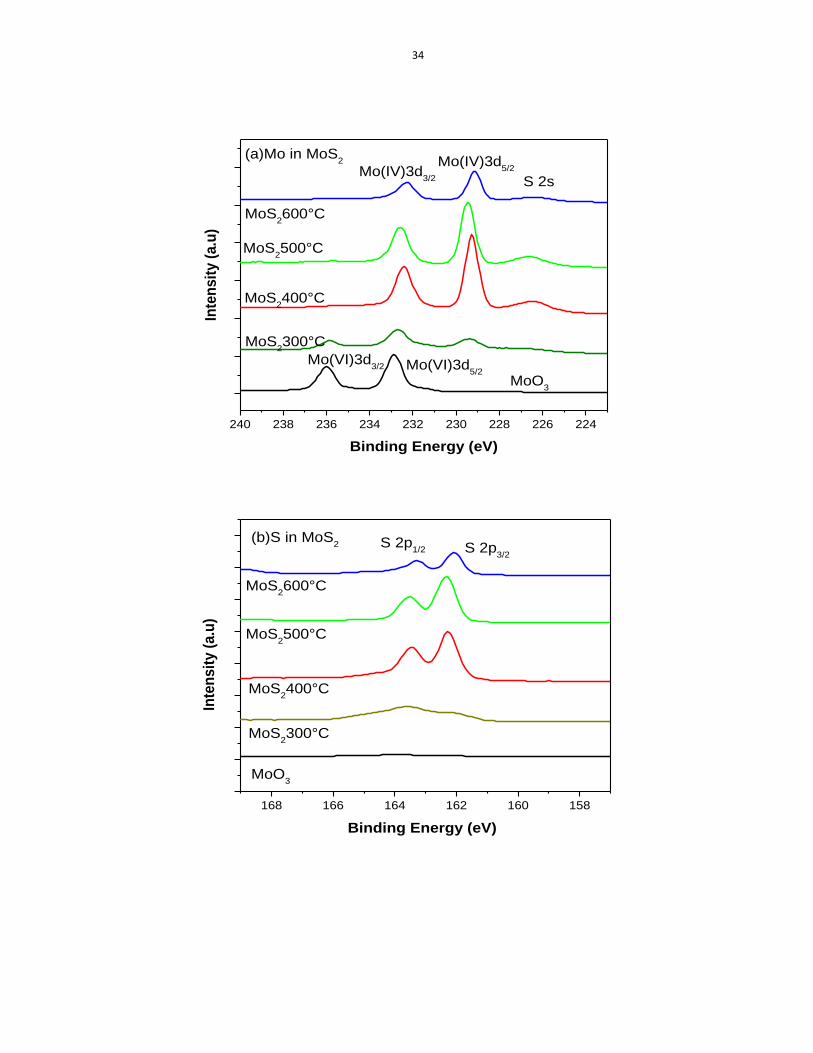
X-ray photoelectron spectroscopy (XPS) was used to study the chemical state of Mo and
S in the as prepared MoS2 deposited Ti foil electrodes, as shown in Figure 12.
The high-resolution XPS spectra in the Figure 12 illustrate that, for the unsulfidized
precursor, the bonding energies of Mo 3d3/2 and Mo 3d5/2 peaks are located at 236eV
232.8 eV respectively, revealing the Mo+6
oxidation state in the of compound, which also
confirm that the chemical state of the precursor compound of MoO3 is +6.40a
For the as prepared MoS2 electrodes sulfurized at 400˚C, it could be seen that Mo (IV)
3d3/2 and Mo (IV) 3d5/2 peak at 232.4 eV and 229.3 eV respectively, which indicates that
the comical state of the as prepared electrode at 400˚C has been changed to the oxidation

36
state of +4 for Mo, along with the appearance of the S 2s peak at 226.5 eV. And it is
similar to as prepared MoS2 electrodes sulfurized at 500˚C and 600˚C.
However, for the 300˚C sulfurized MoS2 electrodes, we could see the peaks of Mo in
both +6 oxidation state and +4 oxidation state, with the Mo (VI) 3d3/2, Mo (IV) 3d3/2 and
Mo (IV) 3d5/2 peaks located at 235.9 eV, 232.7 eV and 229.3 eV respectively, which
illustrates that the 300˚C sulfurized MoS2 electrodes still have the initial reactant
chemical state of Mo+6
, so the product could be confirmed to be the MoO3-MoS2
nanocomposites Ti foil eletrocatalyst.
From the Figure 12(b), it could be clearly seen that S 2p1/2 and S 2p3/2 are located at 163.5
eV and 162.3 eV respectively, which shows that the appearance of sulfur with the
oxidation state of -2, at all the synthesized temperatures, which could also confirm that
the as synthesized compounds is really MoS2.43
From Figure 12 (c), (d), (e), (f), O 1s could show that the chemical state of the oxygen is
-2 in the products sulfurized at 300˚C, 400˚C, 500˚C and 600˚C.
So the products prepared above 400ºC could be the MoO2-MoS2 nanocomposites Ti foil
eletrocatalysts.
37
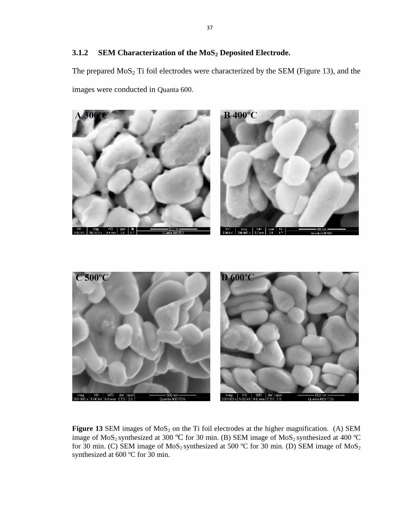
3.1.2 SEM Characterization of the MoS2 Deposited Electrode.
The prepared MoS2 Ti foil electrodes were characterized by the SEM (Figure 13), and the
images were conducted in Quanta 600.
Figure 13 SEM images of MoS2 on the Ti foil electrodes at the higher magnification. (A) SEM
image of MoS2 synthesized at 300 ºC for 30 min. (B) SEM image of MoS2 synthesized at 400 ºC
for 30 min. (C) SEM image of MoS2 synthesized at 500 ºC for 30 min. (D) SEM image of MoS2
synthesized at 600 ºC for 30 min.

38
From the SEM images, we could figure out that:
(1) The products are nanoflakes with the thickness below to 100 nm.
(2) The dispersions of the nanoflakes varied from the products sulfurized at different
temperatures. It could be clear seen that the one sulfurized at 400ºC showed a good
dispersion. The aggregations of the as-synthesized nanoflakes appeared at the
products sulfurized at 500ºC and 600ºC. The eutectic growth was severe in the
samples sulfurized at 500 C and 600ºC, especially the 600ºC one.

39
3.1.3 Hydrogen Evolution Reaction Activities of the As-prepared MoS2 Electrodes.
The electrocatalytic Hydrogen Evolution Reaction activities of the as-prepared MoS2
electrodes were future evaluated directly in the 0.5 M H2SO4 water solution by using the
three-electrode electrochemical workstation.
Just as the described in table 5, the parameter of the electrochemical workstation is
suitable for the testing of MoS2 for the HER.
Key features Properties
Model Autolab PGSTAT128N
Potential range +/- 10 V
Electrode connections 2, 3
Current ranges 1 A to 10 nA
Current accuracy +/- 0.2 %
Current resolution 0.0003 %
Maximum current +/- 800 mA (10 A with BOOSTER10A)
Potential accuracy +/- 0.2 %
Potential resolution 0.3 µV
Compliance voltage +/- 12 V
Input impedance > 1 TOhm
Control software NOVA
Table 5 The parameter of the electrochemical workstation (Data from Mettrohm Autolab)
42
The MoS2 Ti foil electrodes were measured by the Linear Sweep Voltammetry procedure
(using the potentiostatic procedure) with a scan rate of 2 mv s-1
. In the measurement, the
MoS2 electrodes were conducted as the working electrodes, while the commercial Pt
electrode was used as the counter electrode, the Saturated Silver Chloride Electrode as
the reference electrode. And the value of the Saturated Silver Chloride Electrode is 0.197
V.
40
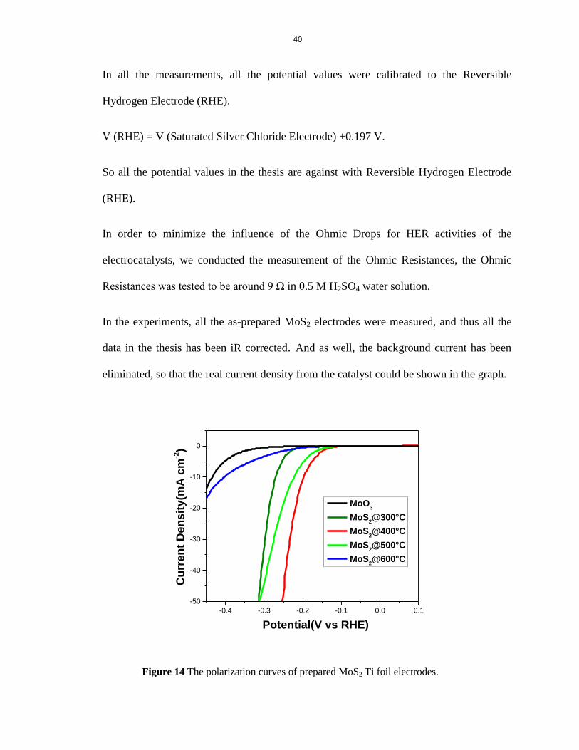
In all the measurements, all the potential values were calibrated to the Reversible
Hydrogen Electrode (RHE).
V (RHE) = V (Saturated Silver Chloride Electrode) +0.197 V.
So all the potential values in the thesis are against with Reversible Hydrogen Electrode
(RHE).
In order to minimize the influence of the Ohmic Drops for HER activities of the
electrocatalysts, we conducted the measurement of the Ohmic Resistances, the Ohmic
Resistances was tested to be around 9 Ω in 0.5 M H2SO4 water solution.
In the experiments, all the as-prepared MoS2 electrodes were measured, and thus all the
data in the thesis has been iR corrected. And as well, the background current has been
eliminated, so that the real current density from the catalyst could be shown in the graph.
-0.4 -0.3 -0.2 -0.1 0.0 0.1
-50
-40
-30
-20
-10
0
MoO3
MoS2@300°C
MoS2@400°C
MoS2@500°C
MoS2@600°C
Cu
rre
nt
De
ns
ity
(mA
cm
-2)
Potential(V vs RHE)
Figure 14 The polarization curves of prepared MoS2 Ti foil electrodes.

41
As can be seen from the polarization curves (i–V plot) in Figure 14, all the prepared
MoS2 electrodes had the performance for the Hydrogen Evolution Reaction, and the
electrode that was made in 300ºC, 400ºC, 500ºC had the relative higher efficiency than
those in other temperatures. And among all the five as-prepared electrodes, the one
prepared in 400ºC showed the highest activities. The Figure 14 showed that for the
electrocatalytic performances of the as-prepared electrodes, there was a ranking and
regulation for the six electrodes.
The MoS2@400˚C exhibited a small onset potential of ~ 0.095 V for HER (Figure 14)
and the tafel slop is of a relatively small value of ~ 40 (Figure 15), which were of great
enhancement in efficiency, compared with the natural bulk MoS2.
-3 -2 -1 0 1 2
0.00
0.05
0.10
0.15
0.20
0.25
0.30
Ov
erp
ote
nti
al(
V)
lgi(lg(mA cm-2))
45 mv/dec
40 mv/dec
MoS2@500°C
MoS2@400°C
PT
30 mv/dec
Figure 15 The Tafel curves of prepared MoS2 Ti foil electrodes.
42
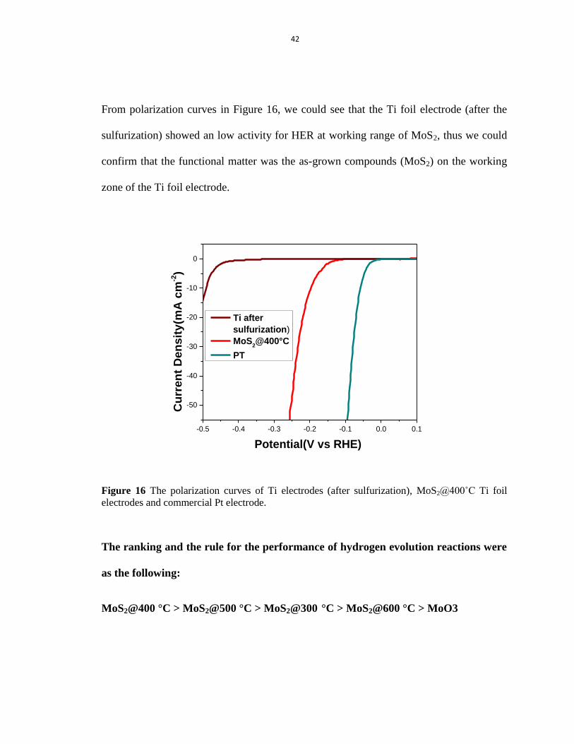
From polarization curves in Figure 16, we could see that the Ti foil electrode (after the
sulfurization) showed an low activity for HER at working range of MoS2, thus we could
confirm that the functional matter was the as-grown compounds (MoS2) on the working
zone of the Ti foil electrode.
-0.5 -0.4 -0.3 -0.2 -0.1 0.0 0.1
-50
-40
-30
-20
-10
0
Cu
rre
nt
De
ns
ity
(mA
cm
-2)
Potential(V vs RHE)
Ti after
sulfurization)
MoS2@400°C
PT
Figure 16 The polarization curves of Ti electrodes (after sulfurization), MoS2@400˚C Ti foil
electrodes and commercial Pt electrode.
The ranking and the rule for the performance of hydrogen evolution reactions were
as the following:
MoS2@400 °C > MoS2@500 °C > MoS2@300 °C > MoS2@600 °C > MoO3

43
The reasons analysis for the ranking and the rule:
(1) From the polarization curves in Figure 15, we could see that the MoO3 electrode had
a very poor electrocatalytic activity for the HER, and after been partly transferred to
MoS2 electrodes, the HER electrocatalytic performance increased greatly.
(2) The performance ranking of the electrodes is as the following:
MoS2 2 5 2 2
We need more proofs to certificate the reasons why the performance ranking is
like this, such as the HRTEM characterization, ICP-OES etc.
(3) Figure 15 & 16 also show the performance of commercial Pt electrode for HER,
which has already been well known as the best electrocatalytic catalyst for the
Hydrogen Evolution Reactions.39
Also, we could get the conclusion form the Figure
15 & 16 that MoS2 is really a promising electrocatalysts which has the biggest
possibility to replace the Pt-group electrocatalysts.

44
3.1.4 Conclusions and Summaries
In this experiment, we designed and prepared a new MoO2-MoS2 nanocomposites Ti foil
electrodes for the first time, which has the relative high eletrcocatalytic activity for the
HER, with a new route for the preparing the high efficient MoS2 elctrocatalysts via CVD
method, which could be synthesized with the low cost materials (earth-abundant Sulfur
and Molybdenum oxide) in the large amount and gravely improve the performance for
the hydrogen evolution reactions.
The electrocatalysts were the prepared by directly conducting the sulfurization of the
deposited MoO3 on the working zones of Ti foil electrodes, which were sulfurized at a
series of temperatures from 300˚C to 600˚C (300˚C, 400˚C, 500˚C and 600˚C) in the
double zones of CVD tube Furnaces.
The as-prepared products deposited on the Ti foil electrodes could be confirmed that the
products sulfurized at 300˚C could be the MoO3-MoS2 nanocomposite Ti foil
eletrocatalyst, while the ones sulfurized above 400˚C (400˚C, 500˚C, 600˚C) would be
the MoO2-MoS2 nanocomposites Ti foil eletrocatalysts.
The as-obtained Ti foil electrodes were directly used as the electrochemistry electrodes to
conduct the test of the efficiency of the eletrocatalysts, which were sulfurized at different
temperatures.
The ranking and the rule for the performance of hydrogen evolution reactions were as the
following:
MoS2 2 5 2 2 3
45
The MoS2 nanoflakes sulfurized at 400˚ had the best performance for the HER with the
small onset potential of ~ 0.095 V versus reversible hydrogen electrode (RHE) and Tafel
slope of 40 mv/dec, which were highly comparable with (even better than) the most
excellent previous reported results,14-15
while the electrocatalysts had the advantages of
using the abundant and low cost precursor materials and being produced in the large
amount via the easier methods.
MoS2 could be for sure a real promising electrocatalysts which has the biggest
advantages to be the alternative of the Pt-group electrocatalysts.

46
4 Conclusions
In this thesis, we prepared the MoS2-based electrocatalysts using CVD synthesis, and
systematically investigated their HER performance.
The first set of catalysts was prepared by in-situ sulfurization of MoO3 on the surface of
a Ti foil electrode via a CVD process. With increasing the CVD temperature from 300ºC
to 600ºC, gradual evolution of MoS2 and the phase transition of MoO3 to MoO2 were
observed. The catalysts prepared at different temperature showed rather different HER
activities, among which the best catalyst was a MoO2-MoS2 nanocomposites prepared at
400ºC. Further increasing the CVD temperatures resulted in dramatically decreased HER
efficiency of the as-prepared electrocatalysts. It is worth noting that despite a facile
process that can be accomplished within 30 min, the HER performance of the optimized
MoO2-MoS2@Ti electrodes was excellent (an onset potential of 0.095 V versus RHE and
the Tafel slope of ~ 40 mv/dec), surpassing those of most reported MoS2-based
electrocatalysts. We speculate that the optimized composite has a MoO2/MoS2 core/shell
structure, which may account for the outstanding HER activity. However, detailed
structural characterization and mechanism study has not been accomplished within the
scope of this thesis and is still ongoing.
The synthetic strategies are facile and cost efficient. The as-synthesized MoS2 catalysts
have excellent and adjustable HER activities. Our preliminary results demonstrate the
significant influence of synthetic condition on the structure and catalytic performance of
the catalyst. This study confirms the great potential of MoS2 as an alternative to Pt-group

47
metals for hydrogen generation through water splitting, and provides new insights into
the structure control and performance optimization of MoS2-based electrocatalysts.
48
BIBLIOGRAPHY
1. Dresselhaus, M. S; Thomas, I. L, Alternative energy technologies. Nature 2001,
414 (6861), 332-337.
2. Domen, K, < http://www.chemsys.t.u-tokyo.ac.jp/laboratory_domen-kubota_e.
html> Domen-Kubota Laboratory. Dalton T 2009, (45), 10055-10062.
3. Kudo, A; Miseki, Y, Heterogeneous photocatalyst materials for water splitting.
Chem Soc Rev 2009, 38 (1), 253-278.
4. Maruyama, J; Ioroi, T; Siroma, Z; Hasegawa, T; Mineshige, A, Hydrogen
Evolution by Carbonaceous Nanoparticle Aggregates that were derived from Cobalt
Phthalocyanine. Chemcatchem 2013, 5 (1), 130-133.
5. Bell, A. T. etc. <http://www.berkeley.edu/news/media/releases/2009/10/08_
sustainable_ chemistry.shtml>. Alexis Bell Research Group.
6. Huang, X; Zeng, Z. Y; Bao, S. Y; Wang, M. F.; Qi, X. Y; Fan, Z. X; Zhang, H,
Solution-phase epitaxial growth of noble metal nanostructures on dispersible single-layer
molybdenum disulfide nanosheets. Nat. Commun, 2013, 4.
7. MoS2, <http://en.wikipedia.org/wiki/Mos2>.
8. <http://www.ecvv.com/product/3284289.html>. MoS2 powder.
9. Radisavljevic, B; Radenovic, A; Brivio, J; Giacometti, V; Kis, A, Single-layer
MoS2 transistors. Nat Nanotechnol 2011, 6 (3), 147-150.
10. Le, D; Rahman, T. S, Joined edges in MoS2: metallic and half-metallic wires. J
Phys-Condens Mat, 2013, 25 (31).
11. Hinnemann, B.; Moses, P. G.; Bonde, J.; Jorgensen, K. P.; Nielsen, J. H.; Horch,
S.; Chorkendorff, I.; Norskov, J. K., Biornimetic hydrogen evolution: MoS2 nanoparticles
as catalyst for hydrogen evolution. J Am Chem Soc, 2005, 127 (15), 5308-5309.
12. Jaramillo, T. F.; Jorgensen, K. P.; Bonde, J.; Nielsen, J. H.; Horch, S.;
Chorkendorff, I., Identification of active edge sites for electrochemical H-2 evolution
from MoS2 nanocatalysts. Science, 2007, 317 (5834), 100-102.
13. Bonde, J; Moses, P. G; Jaramillo, T. F; Norskov, J. K; Chorkendorff, I., Hydrogen
evolution on nano-particulate transition metal sulfides. Faraday Discuss 2008, 140, 219-
231.

49
14. Li, Y. G.; Wang, H. L.; Xie, L. M.; Liang, Y. Y.; Hong, G. S.; Dai, H. J., MoS2
Nanoparticles Grown on Graphene: An Advanced Catalyst for the Hydrogen Evolution
Reaction. J Am Chem Soc 2011, 133 (19), 7296-7299.
15. Chang, Y. H; Lin, C. T.; Chen, T. Y.; Hsu, C. .; Lee, Y. H.; Zhang, W. J.; Wei, K.
H.; Li, L. J, Highly Efficient Electrocatalytic Hydrogen Production by MoSx Grown on
Graphene-Protected 3D Ni Foams. Adv Mater, 2013, 25 (5), 756-760.
16. Kibsgaard, J.; Chen, Z. B; Reinecke, B. N.; Jaramillo, T. F., Engineering the
surface structure of MoS2 to preferentially expose active edge sites for electrocatalysis.
Nat Mater, 2012, 11 (11), 963-969.
17. Wang, T. Y; Liu, L; Zhu, Z. W; Papakonstantinou, P.; Hu, J. B.; Liu, H. Y.; Li, M.
X., Enhanced electrocatalytic activity for hydrogen evolution reaction from self-
assembled monodispersed molybdenum sulfide nanoparticles on an Au electrode. Energ
Environ Sci 2013, 6 (2), 625-633.
18. Energy Information Administration Office of Energy Markets and End Use.
Annual Energy Review 2012, <http://www.eia.gov/totalenergy/data/annual/index.cfm
#summary > (U.S. Energy Information Administration / Annual Energy Review). 2012.
19. Energy Information Administration Office of Energy Markets and End Use.
Annual Energy Review 2010, <http://www.eia.gov/totalenergy/data/annual/index.cfm
#summary > (U.S. Energy Information Administration / Annual Energy Review). 2010.
20. Lewis, N. S.; Nocera, D. G., Powering the planet: Chemical challenges in solar
energy utilization. P Natl Acad Sci USA, 2006, 103 (43), 15729-15735.
21. Zuttel, A.; Remhof, A.; Borgschulte, A.; Friedrichs, O., Hydrogen: the future
energy carrier. Philos T R Soc A 2010, 368 (1923), 3329-3342.
22. (a) Bard, A. J; Fox, M. A, Artificial Photosynthesis - Solar Splitting of Water to
Hydrogen and Oxygen. Accounts Chem Res, 1995, 28 (3), 141-145; (b) Walter, M. G.;
Warren, E. L.; McKone, J. R.; Boettcher, S. W.; Mi, Q. X.; Santori, E. A; Lewis, N. S,
Solar Water Splitting Cells. Chem Rev, 2010, 110 (11), 6446-6473.
23. Baxter, J. B.; Richter, C.; Schmuttenmaer, C. A., Ultrafast carrier dynamics in
nanostructures for solar fuels. Annual review of physical chemistry 2014, 65, 423-47.
24. Crabtree, G. W.; Dresselhaus, M. S.; Buchanan, M. V., The hydrogen economy.
Phys Today, 2004, 57 (12), 39-44.
25. Chen, Y. Z; Wang, Y. Z; Xu, H. Y; Xiong, G. X, Efficient production of
hydrogen from natural gas steam reforming in palladium membrane reactor. Appl Catal
B-Environ, 2008, 81 (3-4), 283-294.

50
26. (a) Gomez, R.; Fernandezvega, A.; Feliu, J. M.; Aldaz, A., Hydrogen Evolution
on Pt Single-Crystal Surfaces - Effects of Irreversibly Adsorbed Bismuth and Antimony
on Hydrogen Adsorption and Evolution on Pt(100). J Phys Chem-Us 1993, 97 (18),
4769-4776; (b) Norskov, J. K.; Bligaard, T.; Logadottir, A.; Kitchin, J. R.; Chen, J. G.;
Pandelov, S.; Norskov, J. K., Trends in the exchange current for hydrogen evolution. J
Electrochem Soc 2005, 152 (3), J23-J26.
27. Geim, A. K.; Novoselov, K. S., The rise of graphene. Nat Mater 2007, 6 (3), 183-
191.
28. Kong, D. S; Wang, H. T; Cha, J. J; Pasta, M; Koski, K. J; Yao, J; Cui, Y,
Synthesis of MoS2 and MoSe2 Films with Vertically Aligned Layers. Nano Lett 2013, 13
(3), 1341-1347.
29. Wells, A. F., Structural Inorganic Chemistry. Oxford: Clarendon Pressf. ISBN 0-
19-855370-6 1984.
30. Thorsten Bartels, W. B., Lubricants and Lubrication. Ullmann's Encyclopedia of
Industrial Chemistry. Weinheim: Wiley VCH 2003, doi:10.1002/14356007.a15_423
31. Zheng, J; Zhang, H.; Dong, S. H; Liu, Y. P; Nai, C. T; Shin, H. S; Jeong, H. Y.;
Liu, B.; Loh, K. P., High yield exfoliation of two-dimensional chalcogenides using
sodium naphthalenide. Nat Commun,2014, 5.
32. Tye, C. T.; Smith, K. J., Catalytic activity of exfoliated MoS2 in
hydrodesulfurization, hydrodenitrogenation and hydrogenation reactions. Top Catal 2006,
37 (2-4), 129-135.
33. Leliveld, R. G.; van Dillen, A. J.; Geus, J. W.; Koningsberger, D. C., Structure
and nature of the active sites in CoMo hydrotreating catalysts conversion of thiophene. J
Catal 1998, 175 (1), 108-116.
34. Splendiani, A.; Sun, L.; Zhang, Y. B.; Li, T. S.; Kim, J.; Chim, C. Y.; Galli, G.;
Wang, F., Emerging Photoluminescence in Monolayer MoS2. Nano Lett 2010, 10 (4),
1271-1275.
35. Lopez-Sanchez, O; Lembke, D; Kayci, M; Radenovic, A; Kis, A., Ultrasensitive
photodetectors based on monolayer MoS2. Nat Nanotechnol, 2013, 8 (7), 497-501.
36. Tributsch, H.; Bennett, J. C., Electrochemistry and Photochemistry of MoS2 Layer
Crystals .1. J Electroanal Chem, 1977, 81 (1), 97-111.
37. Jaegermann, W; Tributsch, H, Interfacial Properties of Semiconducting
Transition-Metal Chalcogenides. Prog Surf Sci, 1988, 29 (1-2), 1-167.

51
38. Karunadasa, H. I; Montalvo, E; Sun, Y. J; Majda, M; Long, J. R.; Chang, C. J., A
Molecular MoS2 Edge Site Mimic for Catalytic Hydrogen Generation. Science, 2012, 335
(6069), 698-702.
39. Chhowalla, M.; Shin, H. S.; Eda, G.; Li, L. J.; Loh, K. P.; Zhang, H., The
chemistry of two-dimensional layered transition metal dichalcogenide nanosheets. Nat
Chem 2013, 5 (4), 263-275.
40. (a) Chen, Z.; Cummins, D.; Reinecke, B. N.; Clark, E.; Sunkara, M. K.; Jaramillo,
T. F., Core-shell MoO3-MoS2 Nanowires for Hydrogen Evolution: A Functional Design
for Electrocatalytic Materials. Nano Lett 2011, 11 (10), 4168-4175; (b) Firmiano, E. G. S.;
Cordeiro, M. A. L.; Rabelo, A. C.; Dalmaschio, C. J.; Pinheiro, A. N.; Pereira, E. C.;
Leite, E. R., Graphene oxide as a highly selective substrate to synthesize a layered MoS2
hybrid electrocatalyst. Chemical Communications 2012, 48 (62), 7687-7689; (c) Merki,
D.; Vrubel, H.; Rovelli, L.; Fierro, S.; Hu, X., Fe, Co, and Ni ions promote the catalytic
activity of amorphous molybdenum sulfide films for hydrogen evolution. Chemical
Science 2012, 3 (8), 2515-2525; (d) Lu, Z.; Zhang, H.; Zhu, W.; Yu, X.; Kuang, Y.;
Chang, Z.; Lei, X.; Sun, X., In situ fabrication of porous MoS2 thin-films as high-
performance catalysts for electrochemical hydrogen evolution. Chemical
Communications 2013, 49 (68), 7516-7518; (e) Yan, Y.; Ge, X.; Liu, Z.; Wang, J.-Y.;
Lee, J.-M.; Wang, X., Facile synthesis of low crystalline MoS2 nanosheet-coated CNTs
for enhanced hydrogen evolution reaction. Nanoscale 2013, 5 (17), 7768-7771.
41. (a) Lukowski, M. A; Daniel, A. S; Meng, F; Forticaux, A; Li, L. S; Jin, S,
Enhanced Hydrogen Evolution Catalysis from Chemically Exfoliated Metallic MoS2
Nanosheets. J Am Chem Soc, 2013, 135 (28), 10274-10277; (b) Yu, Y. F.; Huang, S. Y.;
Li, Y. P.; Steinmann, S. N.; Yang, W. T; Cao, L. Y., Layer-Dependent Electrocatalysis of
MoS2 for Hydrogen Evolution. Nano Lett, 2014, 14 (2), 553-558.
42. http://www.metrohm.co.th
43. Zhou, W.; Yin, Z.; Du, Y.; Huang, X.; Zeng, Z.; Fan, Z.; Liu, H.; Wang, J.; Zhang,
H., Synthesis of Few-Layer MoS2 Nanosheet-Coated TiO2 Nanobelt Heterostructures for
Enhanced Photocatalytic Activities. Small, 2013, 9 (1), 140-147.