the strength of tubes under uniform external pressure
TRANSCRIPT
C.P. No. 253 (18,398)
A.R.C. Technical Repor:
C.P. No. 253 (18.398)
A.R.C.Technml Report
MINISTRY OF SUPPLY
AERONAUTICAL RESEARCH COUNCIL
CURRENT PAPERS
The Strength of Tubes under Uniform External Pressure
sy i
Wg.Cdr. P. C. Cleaver, O.B.E., D.C.Ae.
LONDON: HER MAJESTY’S STATIONERY OFFICE
1956
PRICE fl 7s.bd. NET

C.P. No. 253
U.&C. No. 621-462 : 531.259.222
neport No. structures 193
November, 1955
The Strength of Tubes Under Uniform External Pressure
by
Vu& Commander P.C. Cleaver, O.LE., D.C.Ae.
This report traces the developent of theorcticel solutions to the problem of detcrminug the strength of tubes subjected to unif'orm external pressure, and describes sn extensive series of tests to check the aoouraoy of the Sturm solutzon to this problem end the effects of ma:erial propertzs on collapse pressure. A total of 530 tests were made covering ranges of 1ength:dismetar from 14.0 to 0.51 and nominal thickness:dismeter from 0.0098 to 0.056.
The mean collapse presswe of the tests dcsqned to check the accuraoz of the Slum solution corrected for eccentricity effects exceeded the meen theoretical collapse pressure by 2.2$, the stz&crd deviation was 7.C$, md the distribution approximately Gaussian. It x concluded that this theory mqq confidently be used to predict the stren@ of tubes u&r uniform external pressure applied to the sides only.

LIST OF CONTEXTS
L?zkE
5
6
6
Introduction
Scope of the Investigation
2.1 Selection of Tubes for the Test Progsme 2.2 Selection of the Range of L/D 2.3 Preparation and Inspection of Specimens 2.4 Materml C0~1tro1 Tests 2.5 Design 0f kit Equipment
2.6 Test Observations
Results
3.1 Calculation of Theoretical Collapse Pressures 3.2 Correlation of Theoretical Collapse Pressures
with Experimentsl Results
Discussion of Results
4.1 Factors Inflwncing Collapse Pressure 4.2 Eccentrz.city of Bore 4.3 Ovelity of the Speomen 4.4 Variation of Material Fropertles 4.5 Analysis of Results
Conclusions
9
9
9
9
9 IO 10 IO II
11
12
LIST OF AWEXDICES
Appendix
Details of Specmens end Results Recorded m Frogrmme of Tests on Tubes Under External Pressure
The Evaluation of Tangent Moduli
The Determination of Correction Factors for Measured Eccentricities of Bore
LIST OF TABIiES
Smmary of Materiel Specifications
Collapse coefficients for Round Cylinders with Pressure Applied to the Sides Only, Ends Smply Supported
I
II
III
Table
I
II
-2-
L_IST OF TUmS (Cc&d)
Master Charts for Estmatlng the C~ll~apse Press~es of Tubes Subjected for Externel Lateral Pressure
Results of Tests on 2$" Dia x 24 S.W.G. x T45 Steel Tubes compared dth Collqse Pressures Pmdlcted by Sturm Theory
Results of Tests on I$" Dia x 22 S.7l.G. x T45 Steel Tubes compared with Collepse Pressures Predicted by Storm Theory
Results of Tests on I" Dla x 24 S.V.G. x T45 Steel Tubes coinpared with Collapse Pressures Predicted by Storm Theory
Results of Tests on 1" Dia x 22 S.W.G. x T45 Steel Tubes compared with Collapse Pressures Predicted by Storm Theory
Results of Tests on I" Dia x 20 S,W.G. x T45 Steel Tubes compared with Collapse Pressures Predicted by Stxrcm Theory
Results of Tests on 1" Dia x 17 S.W.G. x T45 Steel Tubes compared with Collapse Pressures Predicted by Sturm Theory
Results of Tests on I" Dla x 24 S.V.G. x D.T.D. JO5 Steel Tubes compared with Collapse Pressures Predicted by Storm Theory
Results of Tests on 1" DM. x 24 S.1I.G. x T55 Steel Tubes compared with Collapse Pressures Predicted by Sturm Theory
Results of Tests on I" Dia x 24 S.TT.G. x T26 Steel Tubes compared wxth Collapse Pressures Predicted by Sturm Theory
Results of Tests on 1" Dia x 24 S.W.G. x 3.T.D. 102A Steel Tubes compared with Collapse Pressures Predicted ty Storm Theory
Results of Tests on 1" Dla x 24 S.W.G. x T58 Steel Tubes compared with Collapse Pressures Predicted by Sturm Theary
Results of Tests on 1" Dia x 24 S .V.G. Comnercisl Brass Tubing compared %%th Collapse Pressures Predicted by Sturm Theory
Results of Tests on 1" Dia x 24 S.W.G. x D.T.D. 460 Light Alloy Tubes compared wxth Collapse Pressures Predicted by Sturm Theory
&sn Collapse Pressures snd Standard Ikvlations of %xporlmental Results expressed as Percentage of and Percentage Variations from, Collapse Pressures Predictedby Stun3 Theory respsctlvely
Values of Stress Coefficient t/D m-d "/t
$ and non-dimensional coeffxlent 5 92 a function or'
Mean Collapse Pressures and Standard Deviations of Experimental. Results corrected for Eccentrlorty of Bore, expressed as Percentage of, and Percentage Variations frqCollqse Pressures Predxcted by Storm Theory respectively
Table
III J
Iv *
v
VI
VII
VIII
ix
s X
XI *
XII
XIII
XIV
xv
XVI
XVII
XVIII *
-
XIX
-3-
LIST OF lLLusTR,&TIoNS
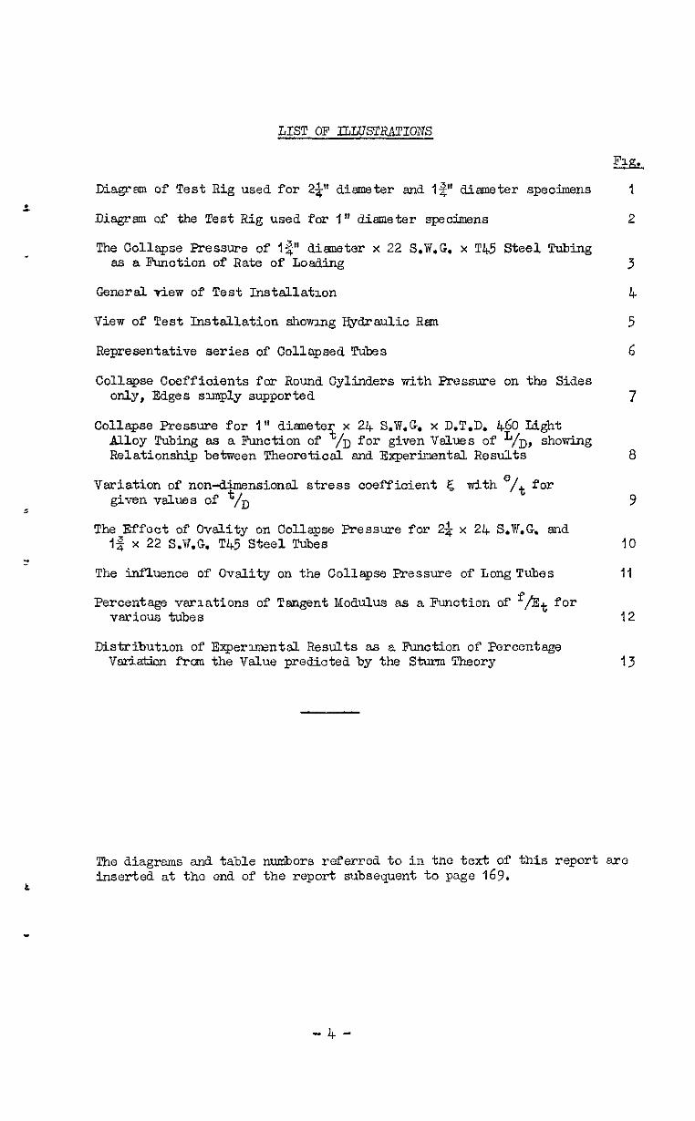
Diagram of Test Rig used for 22 diameter and I$ dimeter specimens 1
Diagz-m of the Test Rig used for I" diameter specimms 2
The Collapse Pressure of I$" dimeter x 22 S.W.G. x T45 Steel Tubing es a Function of Rate of Loadin@: 3
General view of Test Instsllatmn 4
View of Test Installation shcwmg Hydraulic Ram 5
Representative series of Collapsed Tubes 6
Collapse Coefficients for Round Cylinders with Fressure on the Sides only, Edges simply supported 7
Collapse Pressure for 1" dimetex x 24 S.W.G. x D.T.D. 460 Light Alloy Tubing as a J?mction of /D for given Values of '/D, shopring Relationship between Theoretical and Experimental Results 8
Variation of non-dimensionsl stress coefficient 4 with e/t for given values of t/D 9
The Effect of Ovelity on Collapse Pressure for 2& x 24 S.W.G. and 1% x 22 S.B.G. T45 Steel Tubes IO
The influence of Ovslity on the Collapse Pressure of Long Tubes II
Percentage variations of Tangent Modulus e.s a Function cd' f/Et for vario;ls tubes 12
Distsibutlon of Experxmentjl Results as a Function of Percentage Veriation from the Value predicted by the Sturm Theory 13
The diagrams and table numbers referred to in tne text of this report arc inserted at the end of the report subsequent to page 169.
-4-


1 Introduction
The earliest recorded experiment&l work on the problem of the collapse of tubes under externsl pressure was undertaken in 1858 by Fairbairn', who derived an empirical formula to fit the results of 32 tests on wrought iron tubes. Thirty years later Dryan* made a theoretical study of the long tube free from eqy form of end constraint end derived the fun&mental form of the collapse law:-
,KEt 3
P 0 D
Attempts3*4'5 were made to relate this theory with experlmentsl results, but the measured collapse pressures were roughl 3% below the theoretical vcLues. For thicker tubes Csrmsn4 and Stewart s suggested the empirical formula:-
P =A 0
2 +B D
which Wmndenburg6,7,8 continues to reoommend for unfired tubes.
Ths short tube problem wae first solved by Southwell in 1913. His solution contains an unknown term whioh depends on the type of end constraint; in 1925 Cooklo determined the constrlunt constwt for the case where the ends are simply constrained to remain circular. In a seri s f' papers published shortly after Southwell's original Work, Southwell ll,l~,l~ together with Cook'4 and Carmeni attempted to correlate the long and short tube solutions by deriving apgroximate methods for estimating collapse pressure over both ranges.
In 1914 van Nise% derived a solution to the short tube problem with simple end constraints and subjected to lateral pressure only, which contained no unihmvn terms. In a later psperd7 published in 1929, this solution was extended to cover the wse where lateral and end pressure is applied to the tube. Tokugawal8 obtained a similar solution to this latter problem at about the some time.
The solutions of Southwell, van IvIises and Tokugawa are sll, however, extremely laborious to apply, and in 1934, Windenburg snd Trilling'9 derived a simplified formula, based on vonhises' work, which was subsequently adopted by the American authorities for the design of unfired vessels subjected to externsl pressure.
In 1941, stwm20 extended the rigorous theoretical solutions by solving the problem for the slternative form of end constraint in which the ends of the tube are constr~ned to remain both circular and cylindrical, for both forms of pressure loading. His work, Which i.3 thUS the first complete theoretical treatment of the problem, is presented in the simplified form of equation (I), the values of 'K' being presented graphically for a wide range of length, diameter, and thickness for all combinations of pressure loading snd end constraint.
-5-

In 1947 Storm and O'Brxen 21 suf.~ostcd thact the thecry mzy be extended to the very short tube rsnze, where faxlure motes towards the plzstx mode, by scbstituting for Young's Modulus, the tsngentnodulus of the meterisl at the direct oompresslve stress ~ndxozd aL collwse. The collapse formula therefore takes the final fo-rm:-
F
The expermectal works of Cmcm4 snd Stewart5 winch were confined to long tubes manufactured by technique s which arenowobselete, gave poor agree- ment wth theory. A short series of tests by C0rne11~~ indicated however that collapse pressures almost equsl to the theoretxslly predicted values msy be attained vrlth long specwns of modern drawn tubes. For the short tube range, published test results gave poor agreement with theory, snd ul no case were data available from which tangent moduli could be dewrmined.
Th1.s report describes a comprehensive experimental. investigation which was undertaken to cluck the validity of Stwm's solution for tne simple end constraint snd la%zal prossure case, snd the effects of relevant mechanxsl properties on collapse pressure.
2 Scope of the Investigation
2.1 Selection of Tubes for the Test Programme
The validity of Storm's theory wss checked by a series of tests on tubes msnufaotured to Brltlsh Standard ZQeoificatlsn T.45, D/t covered by tine tests extended from
The range of nominal L?/t = 102 (2$” dia. x 24 S.V.G.) down
to D/t = IT,85 (I" dm. x 17 S.W.G.) as detaiLed ILL the followng table:-
Tube Size
29 dla . x 24 SV G . . .
13"dia x22SWG ‘I . . . .
I” die.. x 24 S.w.G:
1”dia x22S.VG . .
I” dia. x 20 S.W.G .
1" dia . x 17 S.V.G.
?~onllns3. v/t 102
62.5
45.5
35.7
27.8
17.85
The mechsnicjl properties, the effects of which were lnvestlgated in the second part of' the investigatzon, IwreYoung's Modulus end the rattle of the O.l$ proof to ultunatc strengths; earlier work 3, 4, 2 2 2 5 on cylinders subjected to axial compressmn mdicated that the latter might be a factor influencing collapse. Two series of tests on light alloy tubes to Speczfxatlon D.T.D. 460 and oommcrcialbrass gave, wrrth 'the tests on steel tubes, an overall modulus ratio of &out 3:l. The effects of the proof:ultlmate strength ratio was u'westigated by five serxes of tests xhlch, with the T.45 results, covered the follcwingncmti&L range of this parameter:-
-6-
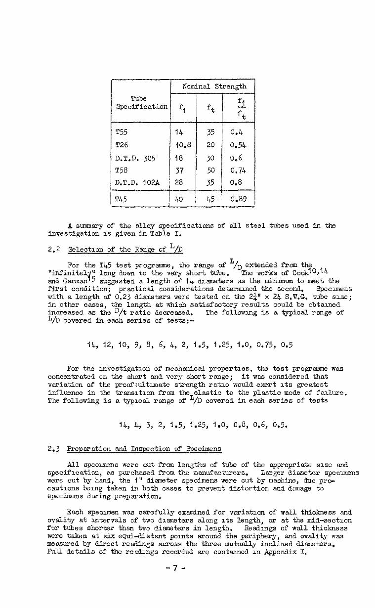
1 Wominsl Strength
T55 14 35 0.4
T26 10.8 20 0.54
3.T.D. 305 18 30 a6 T58 37 D.T.D. 102A i 28
A s-ary of the alloy specifications of all steel tubes used in the investigation is given in Table I.
2.2 Selection of the Range cf L/il
For the T45 test programme, the range of "/D extended from the "infinite1 U
v 5 long aown to the very short tube. The works of Cookzo,'4
end Carmen suggested a length of 14 diameters as the minlmvm to meet the first condition; practicsl considerations deteranned the second. Specimens with a length of 0.23 diameters were tested on the 2p x 24 S.W.G. tube size; in other oases, the length at which satisfactory results could be obtarned inoreased as the D/t ratio decreased. L/b covered in each series of tests:-
The following is a typical range of
14, 12, IO, 9, 8, 6, 4, 2, 1.5, 1.25, 1.0, 0.75, 0.5
For the investigation of mechanic& propertaes, the test programme was concentrated on the short and very short range; it was considered that variation of the proof:uJ.tlmate strength ratio would exert its greatest influence in the transition from the elastic to the plastic mode of failure. The following is a typical range of L/D covered in each series of 'rests
14, 4, 3, 2, 1.5, t.25, 1.0, 0.8, 0.6, Q.5.
2.3 Preparation and Inspection of Specimens
All specimens were out from lengths of tube of the appropriate size and specification, as purchased from the manufacturers. Larger dismeter spe~mens
were cut by hand, the 1 It diemeter specimens were cut by machine, duo pro- cautions being taken in both cases to prevent distortion and damage to specimens during preparation.
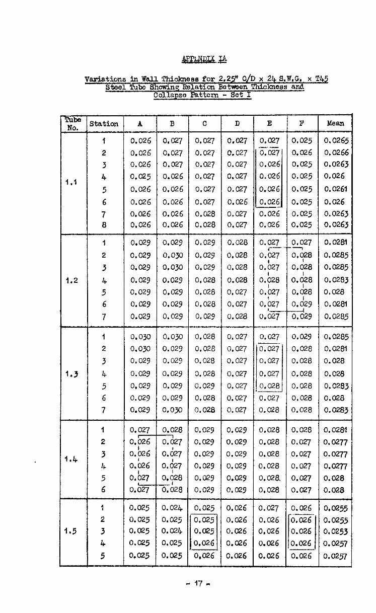
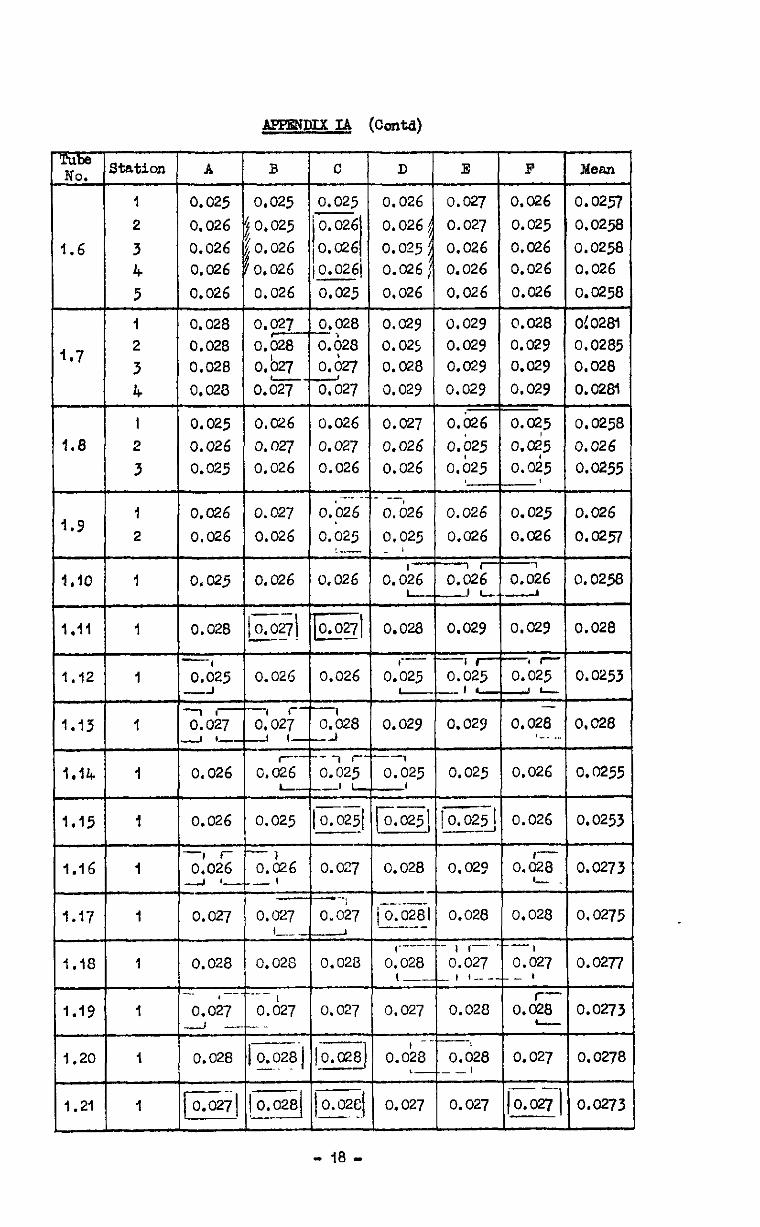
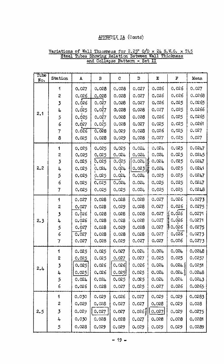
Each specimen was carefully examined for variation of wall thickness end ovality at mtervals of two diameters along its length, or at the mid-section for tubes shorter than two dimeters in length. Readings of wall thickness were taken at six equi-distant points around the periphery, and ovality was measured by direct readings across the three mutually inclined diameters. Ml details of the readings recorded ere contarrned in Appendix I.
-7-
2.4 Material Control Tests
Specimens of each original length of tube were subjected to both longi- tudinal and transverse tensile tests. Longitudinal specimens were machined from a section of the tube es cut, the tube curvature being unaffected. Transverse specimens were machined from a section of tube which had been opened E out, and which had possibly therefore been subjected to work hardening. Details of the mein strength characteristics for eaoh control specimen sre given an Appendix I, together wLth the identification of pressure test specimens applicable thereto.
Although the failure of the tubes takes place under compressive loading, it was decided that results would be related initially to the tensile proper- ties of the material. These are unlikely to differ to amerked degree from the aheraoteristics exhibited under compressive loading and are more readily available.
2.5 Design of Test Equipment
The test equipment mss deso.gned so that the ends of the specimens were simply constrained to remain circular. For the 2$" dia. end I$" dia. tube sizes, the ends of the specimens were supported on knife edged plugs as shown in Fig.1. For al.1 other tests, the specimens were supported on parallel plugs es shown in Fig.2. The degree of end constraint thus applied rnw vary from specimen to specimen due to variations of tube size within permitted menufactwug tolerances. The high standards achieved. in the msnufaoture of modern drawn tubing reduce these effects to a minimum and little variation of fit was noted during assembly.
The end plugs were carried on a heavy centrel shaft, one end of which wsa drilled to vent the inside of the specimen to atmosphere. Relative movement between the specimen and the end plugs was thus resdily absorbed.
The inside of the specimen was seated by aleyer of cellotape over the joints between the specimen and the end plugs, end at higher pressures, this was reinforced by a section of cycle inner tube. Seepage of fluid elong the thread. between the shaft and end plug was eliminated by fitting a counter- sunk nut and tightly fitting seal washer as shown in Fig.2.
When ready for test, the entire assembly was plaoed inside a hydraulic cylinder and suitably vented to atmosphere. A number of these cylinders were available, and in each case the smallest cylinder was used into mhich the specimen would fit. The volume of oil under pressure and hence the stored energy were thereby reduced to aminimum, and the region of failure localised.
Pressure was applied either by a norm&i aircraft type bend pump, or by a compressed air operated hydraulic rem. results of which me shown in Fig.5,
An initial series of tests, the indicated that the rates of application
of pressure obtainable with this equipment did not influence collapse strength.
Photographs of the test installation are shown in Figs.4 end 5 respectively. ;
2.6 Test Observations
Collapse pressures wore read directly from large diameter Bout-den gauges which bed been specially celibrated. In general, collapse we3 readily indicated both audibly, and by a sudden fsll In pressure. specimens of 2$" dia. tube however,
For the longer it could only be detected by rsising the
pressure very slowly by hand pump, end noting the change in 'feel' which
-8-

occurred at the moment of collapse. Some difficulty was also encountered in detecting the collapse of very short tubes, where the pressure drop ceused by the small volunwtric change did not slwqs register clearly on the pressure gauge. In some cases the formation of successive lobes around the periphery of the specimen could be detected audibly; the collapse could thus be localised and related to minor variations of w&L1 thickness in the tube.
Fig.6 shows a representative series of collapsed tubes.
3 Results
3.1 Calculation of Theoretical Collapse Pressures
Theoretical collapse pressures were calculated by the method suggested by Sturm and OQrian2'. Tangent moduli were determined mathematically from the 'five-point' formula for numerical differentiation derived by Bickley26 as outlined in Appendix II. For greater accuracy of analysis, the value of the collapse coefficient 'K' was xx-computed for a series of values of D/t within the range covered by the experimentsl programme. The vslues of collapse coefficient thus obtained are presented in tabular form in Table II and graphicslly in Fig.7.
A master chert for estimating oollapse pressure is in Table III; colwms l-6 of this chart irre universally applicable to tubes of the range of t/D covered by this investigation. The values of Et are determined for the appropriate value of f& obtained from the load-extension readmgs taken during each control specimen test, The collqse pressure is deter- mined as the product of the figures in columns 3, 5 and 7, and is applicable to those pressure spcwaens related to that particular control test. Table III includes the values of Et and collapse pressure for control spocvncn Bl of the D.T.D. 460 light alloy tests.
3.2 Correlation of Theoretical Collspse Pressures with Experlmentsl Results
Collapse pressures were calculated, at appropriate steps over the complete range of I'/D, for the tangent modulus variation obtained from each control test specimen. The results were tiien presented grsphically as a function of t/a for given vslues of L/D; a typical series of curves are shown in Fig.8. ExperYnentsl results related to each control specimen were then plotted, the arithmetic mean of the measured wall thicknesses of the specimen being plotted on the abscissa scale. Discrepancies between the theoretical and experimental results were then read directly from these CupVeS. The results of es& series of tests are shown in Table IV to WI inclusive, the difference between the theoretical and experlmontsl results being expressed as a percentage of the former.
4 Discussion of Results
l+.f Factors Influencing Collapse Pressure
e The theory as postulated by Stwm predicts the collapse pressure of
tubes which are geometrically perfect; practical tubes will vary from this perfect shape within permitted msnufacturing tolerances. Such variations may be resolved into:-
. (a) Eccentricity of the bore relative to the external surface.
(b) Variations from the 'zx.e circular shape.
-Y-
Scme account must also be taken of variation along the length of the tube of those mechanical properties which mey affect collapse pressure. The influence of these three factors is discussed in the following paragraphs.
4.2 Ecoentricity of Bore
The stress distribution in en eccentrically bored tube subjeoted to both internal and external pressure was determined by Jeffery27,28, Correction factors for measured eccentricities were spplied to the experimental. results by the methods outlined in Ap-pendzx III. Since in msny oases, tube wall thickness had been measured only to the nearest O.OOl", variations of this order end less were ignored from an eccentricity view point.
Eccentricity of bore exerts its greatest effects on thicker and shorter tubes, where collepse occurs at stresses beyond the elastic limit; under these conditions ccmperatively small increases in stress may produce en appreciable reduction of tangent modulus.
The collapse pattern could in almost every case be related to minor variations of well thickness of the specimen, thus indicating the predominant effect of this variable.
4.3 Ovality of the Specimen
Theoretical work by Tlmoshenko 29 is confined to the cese in which the initial distortion end the final collepse pattern agree. Measurements recorded in Appendix I indicate however the very complex nature of the initial deviations of any tube; in most cases the axis of the major dimension changes appreciably along its length. The problem is further complicated by the laok of any oleerly defined dab with which to compare the strength of otherwise geometrically similar tubes,
The agreement obtained between the experimental results end the Sturm theory suggested that the theoreticelly predicted collapse pressure could be usea as the datrrm. The ovelity of the 2$" dia. am3 I$" dia. tubes was there- fore plotted as a function of the percentage variation of the measured collqse pressure from the theoretical value, ovality being defined es:-
Ovality = Dmax-Dmin
D nominal
The results plotted in Fig.10 indicate that within the measured limits, ovslity exerts no systematic influence on collapse pressure, ALfurther snslysis on cd.1 the longest tubes (L/D = 14), the results of which sre plotted in Fig.11, gave a similar result.
4.4 Variation of h~ateriel Properties
Tangent Modulus, the only material property used in the Sturm theory, is notably inconsistent, not only betseen semples of materiel manufactured to the same specification, but also between tiferent specimens cut from a single large ssmple. To obtain a measure of its variation, a subsidiary series of tests were undertaken on tensile specimens cut from long lengths of tube taken at random from store. Details of the test observations are in Appendix I, and the results are shown graphically in Fig.12. Since f&is a paremeter determined solely by the collapse coefficient and the tube geometry, the percentsge variation of tangent modulus is a direct measure of the variation of collapse Foressure.
- IO -

4.5 Anslgsis of Results
A statistlo&. analysis of the results of the tests on !I45 tube presented in Table XVII lnd.icated that their mean value exceeded the mean vslue of the theoreticsl results by 0.2% with a stsoldard deviation of 7.2$.
Of the three factors which influence collapse pressure, no systemat.tlc variation could be found for ovslity snd variation of tangent modulus. The results corrected for treasured eccentricity of bore by the method outlined in Appendix III are shown in Table XIX. Those corrected results for T45 gave a mean collapse pressure wklch exceeded tk theoretical mean by 2.2$ witha standard deviation of 7.N. In only one osse, the Z&" dia. x 24 S.W.G. series of tests, does the collwse pressure drffer from the theoretical mean by more than 3 standard deviations; 111 this ease it was 3.5. ThLs dis- crepsncy is consldered to be due to the difficulty, which was noted earlier in the report, in obtainmg reliable results with this particular size tube. The T45 distribution curve was lepto-&tic, the following table showing the ma~character~st~cs:-
K=w Normal Gaussion T.45
Distribution Distribution
+u 31% 23.4%
3.96 u % 3.0$
d.09 u 00% 1%
The results of smaller numbers of tests on T55, T26, D.T.D. 102A and D.T.D. 460 showed that their mean collapse pressures differ from the theoretical meen by less than j$ with standard deviations from $ to 12%. The results of tests on T58 gave a mean value % higher than the theoreticsl mean with a standard deviation of 1%; slthough the difference in the mean is higher than for the other materials mentioned above, it is less than three standard deviations of the mean and is therefore statistlcslly acceptable. Two other materials D.T.D. 305 snd commercial brass have mean values whloh differ from the theoretlosl mean by 1% snd 20$ respectively snd in these cases the theory deflnltely does not hold. These discrepancies may be due either to gross experimental error or to wide variation of rnechsnicsl properties from those recorded duclng the control tests. It is not thought that these discrepancies invalidate the Sturm theory which gives acceptably close prediction in all other cases.
An examination of Plg.12 shows that a large variation in mechanical properties may be expected along sny given length of tube and this could well be sufficient to account for the whole of the scatter in the results obtained except for the cases of D.T.D. 305 and ccnmeroul brass.
5 Conclusions
The results of the first part of the expervnentsl programme which was undertaken on T45 tubes mnduates that the mathematical theory developed by R.G. Storm at the University of Illmois, predicts the oollspse pressure of modern drawn steel tubes to ah@ degree of accuracy for the condition where pressure is applied to the s&s of the tube, and the tube ends sre simply constrained to rem- circular. The theory is applicable to tubes of all lengths, for both the elastic and plastic modes of Palure, collapse pressure being deTermined from the formula:-
-11 -
p = KEt ; 3
0 (3)
where K is a coefficient d.etzrmined by the dimensions of the specimen,
Et is the value of the longitudinal tensile tangent modulus at the direct compressive stress induced at c&lapse.
The result of the second part of the experlncntsl progrmzce*indicates that, in general, variations of the ratlo of proof to ultimate strength are insignificant, and confirm that the tangent r?odulus is the only mechanical property which exerts any influence on collapse pressure. Accurate informa- tion on the variation of thxi parmeter under longitudinal tensile loading permits equation (3) to be applied with complete corx?idence. For practical spplications however the use of a composite by Sturm end O'Brxcn2l is probably desirable.
"least value" curve as suggested
Eccentricity of the bore relative to the exterior surface of the tube is the predominant manufacturing vsrisble affecting collapse strength, but for eccentricities within the limits imposed by current specifications, its effects we smell, and for practical purposes, may be neglected.
Vsriations in the circularity of the tube exert no measurable systematic influence on collspse strength, snd provided such variations are within the limits imposed by current tube specifloations, this mqy also be neglected.
1% Author
1 Fsirbaun, W.
2 Bryan, G.H.
3 Carmen, A.P.
4 Carmen, A.P. and Carr, M.L.
5 Stewart, R.T.
Title. etc.
Resistace of tubes to collapse Philosophical Transackons 1858, Britzsh Association Report 1857,
P.389 P.215
Applicatzon of Energy Test to Collapse of Long Thin Pqze under External Pressure PI-CC. Cambridge Ph-rlosophiosl Society, vOi.6, p.287, 1888
Resistance of Tubes to Collqse Physical Review, Vo1.21, December, i905, PP. 381-387 Scientific Abstraots, lgO6, No.239
Resistwce of Tubes to Collapse University of Illinois Bulletin, Yo1.3, No.17 June,1906 ScientlPic Abstracts 1906, No.1986
Collapse Pressures of Bessemer Steel Lap-Welded Tubes 3" to IO" in dismeter Transactions of American Society of Mechanxal Engineers, Vo1.27, pp.730-822, 1906
- 12 -
Ro. Author
6 Windenburg, D.F.
7 Flindenburg, D.P.
a
9 Southwell, R.V.
IO Cook, G.
11 Southwell, R.V.
12 Southwell, R.V.
13 Southwell, R.V.
14 Cook, G.
15 cemm, A.P.
16 van Mises, R.
$7 van Mists, X.
ia [email protected]@wa, T .
RElmims (C0nt.d)
Title, etc.
Naster Charts for the Design of Pressure Vessels under External Pressure Transactions of the Airerican Society of Mechanicsl Engineers, Vol.69, pp.345-351, 1947
Vessels under Bxterndl Pressure Nechanicsl Bngmeermg, Vol. 59 pp.601-608 Auyst, 1937
A.P.I,/A.S.M.E. Code for the Design, Construc- tion, Inspection and Repair of Unfired Pressure Vessels for Petroleum Liquid and Gases 1951
On the General Theory of Elastic Stability Philosophical Transactions, Series A, Vo1.213, pp.1a7-244, 1gl3
The Collapse of Short Thin Tubes by External Pressure Philosophicsit Msgasme, V01.50, pp.844-848, October, 1925
On tne Collapse of Tubes by External Pressure Philosophicsl Xsgazme, ‘~01.25, pp.687-698, WY, 1913
On the Collapse of Tubes by External Pressure Philosophical Magazine, Vo1.26, pp. 502-511, September, lYl3
On the Collapse of Tubes by External Pressure Philosophical Magazine, Vol.29, ~~-67-77, January, 1915
The Collapse of Short Thin Tubes by External R-e ssure Philosophical Msgszme, Vo1.28, pp.51-56, July, lYi4
The Collsqzse of Short Thin Tubes University of Illinois Engineering Experlmentsl Station, Bulletin No.99 June, 1917
Der Kritische Aussendruck Zylindrischer Rohre Zeitung v.D.I., v0i.58, pp.775~755 1914
Der Krit~sche Aussendruck f&z Allseits belastete zylindrische Rohre Pest zw 70 Geburtstag van Prof. Dr. A Stodola, Zurich pp.418-430 t929
hiodel Experiments on the Elastic Stability of Closed and Cross Stiffened Circular Cylinders under Unlfom External Pressure Proceedings of the Wbrld Engineering Congress, TO~V~, ~01.29, ~~24.9-279 f929
- I3 -
1%
19
20 Sturm, R.G.
21
22
23 Bowers, I.G.
24 Douglas, wio. and Csrmichael, D.
25
26
27
28 Jeffery, G.B.
29 Tunoshenko, S.
Author Title, etc.
Windenburg, D.F. end Trilling, C.
Collapse by Instability of Thm Cylindrical shells under Extemsl Pressure Trensactxons of the American Society of Mechanical Engineers, ~01.56, Paper &P&-56-20
Stm, R.G. and O'Brien, H.L.
Cornell, SldneY
Shelley, J.H.
Bickley, W.G.
Jeffery, G.B.
REFERENCES (Co&d)
A Study of the Collapsing Pressure of Thin Walled Cylinders University of Illinois Fmgineering Experimental Station Bulletin No.329 1941
Computing Strength of Vessels Subjected to External Pm ssure Trwsactlons of the American Society of Mechanical Engineers, vol.69, pp.353-358 I 947
The Collapse of Long Cylindrical Shells under External Pressure Proceedings of the Society for Experimentsl Stress Analysis, Vol.VI, No.1
Compression Tests on Short Tubes M.A.P. Soientif'ic and Technical Memorandum No.l7/44 Flight Refuelling Report
Determination of the Minimuin Values of Strength and Stiffness of Various Metals which only just Comply with the Requirements of their Respective Specifications R.A.E. Report&T.5587
Strength Data on Circular Metal Cylinders Under Axial Compression R.A.E. Technical Note Structures 122
Formulae for Numerical Differentiation Mathematical Gazette, Vol.25, pp.i9-27, 1941
Plane Stress and Plane Strain in Bi-Polar Co-ordinates Phllosophicsl Transactions of the Roysl Society Series A, Vo1.221, 1921
The Stresses in Cylinders end Pipes with Eccentric Bore Report of the British Association for the Mvsnoement of Science, 1921, pp.356~358
Applied Elasticity pp.242-245
- f4 -
APPENDIX I
Iktaals of Specimens and Test Observations
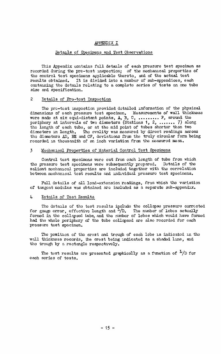
This Appendix contains full details of eaoh pressure test specimen as recorded during the pre-test inspection; of the mechanical properties of the control test specimens applicsble thereto, m-d of the actual test results obtained. It is divided into a number of sub-sppendices, each contuing the details relating to a complete series of tests on one tube sise zmd specification.
2 Details of Pre-test Inspection
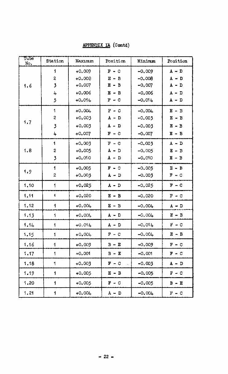
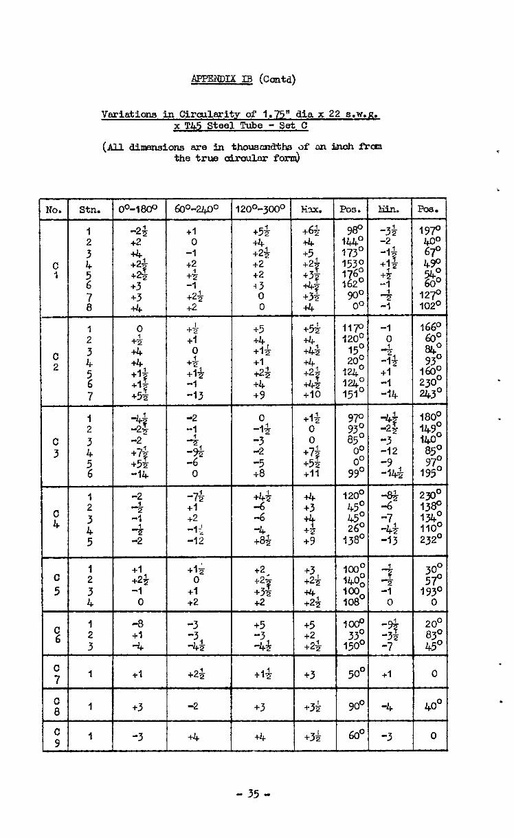
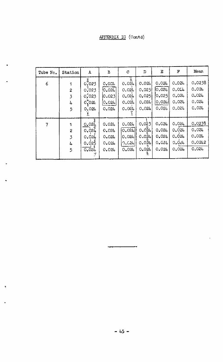
The pro-test inspection provided detailed information of the physical dimensions of each pressure test specimen. Measurements of wall thickness were made at six equi-distant points, A, B, C, . . . . . . . . . F, S.TOUII~ the periphery at intervdls of two diameters (Stations I, 2, .,..... 7) slang the length of each tube, or at the mid point of tubes shorter then two airmeters in length. The ovslity was measured by direct readings 5croSs the diameters AD, BS and CF, deviations from the truly ciroulsr form being recorded zn thousandth of en inch variation from the measured mean.
3 Mechanical Properties of Material Control Test Specimens
Control test speoimons were cut from oaoh length of tube from which the pressure test specimens were subsequently prepared. Details of the salient moohsnical properties are included together with the correlation between mochonical. test results and tividusl pressure test specimens.
Pull deteils of all load-extension readings, from which ths variation of tongent modulus was obtained ore included as a separate sub-appendix.
4 Details of Test Results -
The details of the test results include the collapse pressure oorrccted for gouge error, offactive length and L/D. The number of lobes actuslly formsd in the collapsed tube, and the nmber of lobes which would have formed had the whole periphery of the tube collapsed sre slso recorded for each pressure test specimen.
The position of the crest and trough of ench lobe is indicated in the wall thickness records, "he crest being indicated as a shsded line, snd the trough by a rcctengle respectively.
The test results are presented [email protected] as a function of '/D for each series of tests.
- 15 -
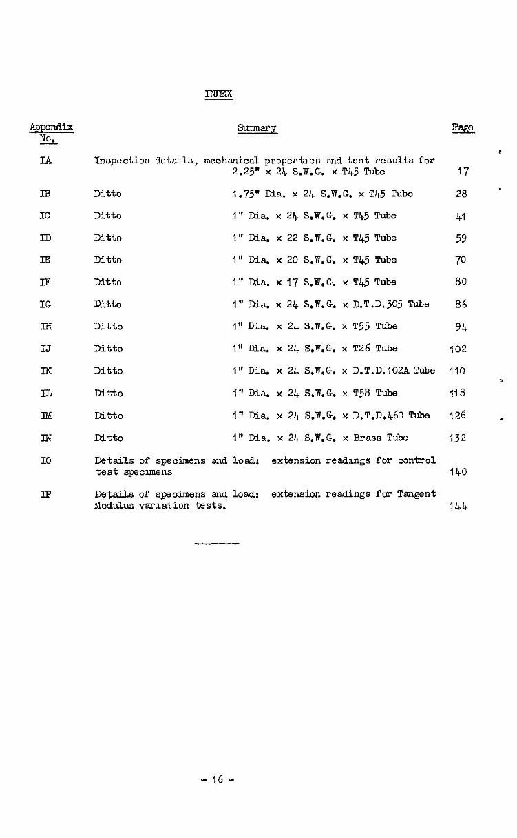
Appendix No.
IA
IB
IC
ID
rf3
IF
IG
IH
IJ
IK
Iz
IId
IN
IO
Ii?
INDEX
Inspection detads, mechanical properties and test results for 2.25" x 24 S.W.G. x T45 Tube
Ditto 1.75" Dia. x 24 S.W.G. x T45 Tube
Ditto I" Dia. x 24 S.W.G. x T45 Tube
Ditto 1" Dia. x 22 S.W.G. x T45 Tube
Ditto I" Dia. x 20 S.W.G. x T45 Tube
Ditto I" Dia. x 17 S.W.G. x T45 Tube
Ditto 1" Dia. x 24 S.W.G. x D.T.D.305 Tube
Ditto 1" Dia. x 24 S.W.G. x T55 Tube
Ditto I" Dia. x 24 S.W.G. x T26 Tube
Ditto I" Dia. x 24 S.W.G. x D.T.D.102A Tube
Ditto <I@ Dia. x 24 S.W.G. x T58 Tube
Ditto I" Dia. x 24 S.W.G. x D.T.D.460 Tube
Ditto In Dia . x 24 S.W.G. x Brass Tube
Details of specimens end lo& extension readmgs for control test specmens
Deta;iLs of specimens sncl load: extension readings fcr Tangent Moclulua vmlation tests.
=%iE
J
17
28 '
41
59
70
80
86
94
102
110 ,
118
126 .
132
140
144
- 16 -
lcube NO.
1.1
1.2
1.3
1.4
1.5
Vaxiatima in wall Tibknes~ for 2.25" o/D x 24 S.W.G. x T42 Steel Tube ShowLng Relation Betwaen Thiokness and
Collapse %ttcm - Set I
ltation A B c D E
1 0.026 0.027 0.027 0.027 2 0.026 0.027 0.027 0.027 3 0.026 0.027 0.027 0.027
4 0.025 0.026 0.027 0.027
5 0.026 0.026 0.027 0.027
6 0.026 0.026 0.027 0.026
7 0.026 0.026 0.028 0.027 a 0.026 0.026 0.028 0.027
0.026 0.026
I 0.029 0.029 0.029 0.028 0.027
2 0.029 0.030 0.029 0.028 0.Z
3 0.029 0.030 0.029 0.028 0.b27
4 0.029 0.029 0.028 0.028 Oh28
5 0.029 0.029 0.028 0.027 o.b27
6 0.029 0.029 0.028 0.027 oh27
7 0.029 0.029 0.029 0.028 0.027
I 0.030 0.030 0.028 0.027 2 0.030 0.029 0.028 0.027 3 0.029 0.029 0.028 0.027
4 0.029 0.029 0.028 0.027
5 0.029 0.029 0.029 0.027 6 0.029 0.029 0.028 0.027 7 0.029 0. 033 0.020 0.027
0.027 -.
0.028
I 0.027 0.028 0.029 2 0.E zk?7 0.029
3 o.b26 0.627 0.029 4 Oh26 0.627 0,029
5 oh27 O.d28 CA28
0.029
6 0.027 0.029
0.029 0.028
3.029 0.028
3.029 0.028
0.029 0.028
0.029 0.028.
0.029 0.028
1 0.025 0.024 0.025 3.026 0.027 2 0.025 0.025 0.025 3.026 0.026
3 0.025 0.024 0.025 3.026 0.026
4 0.025 0.025 0.026 3.026 0.026
5 0.025 0.025 0,026 3.026 0.026
F
0.025 0.0265
0.026 0.0266
0.025 0.0263
0.025 0.026
0.025 0.0261
0.025 0.026
0.025 0.0263 0.025 0.0263
0.027 '7 0.q28
0.028
O.d28
O&S
o.d29 4 0.029
0.020-I
0.0285
0.0285
0.0283
0.028
0.028-l
0.0205
0.029 0.0285
0.020 0.0281
0.028 0.028
0.020 0.028
0.028 0.0283
0.028 0.028
0.028 0.0283
0.020 0.0281
0.027 0.0277
0.027 0.0277
0.027 0.0277
0.027 0.028
0.027 0.028
0.026 ..--. 0.026 0.026
0.026
0.026
Mean
0.0255 0.0255 0.0253
0.0257
0.0257
No.
1.6
I.7
1.8
1.9
1.12
1.15
1.16
f.17
1.18
1.19
1.20
1.21
ltatson
1
2
3 4 5
I 2
3 4
1 2
3
I 2
I
I
I
I
1
I
I
I
1
I
1
1
AtB IC D t E F
0.028 o.br 0.627
0.028 0.027 0.027
0.025 o.cQ6 0.026 0.026 0.027 0.027 0.025 0.026 0.026
---- ' 0.026 0. 027 0.026 0.026 0.026 0.025
?.-
0.025 0.026 0.026
--
O.Oi+.d27 1 0.027
~. ~,
0.028 11 0.028) ~~0.028 -~. --
I
I
I *
0.026 0.027 0.026, 0.027 0.025$ 0.026 0.026; 0.026 0.026 0,026
0.029 0.029 0.025 0.029 0.028 0.029 0.029 0.029
0.027 0.626 0,026 0.b25 0.026 O.b25
-
i:i126 0.026 0.025 0.026 _ 4 O.d26 0.02; 1
I JL
0.028 0.029
---
0.028 0.029
_-._-_- ;0.0281 0.028 -----
t-
--- I I- 0.028 0.027
,- I t---
0.027 0.028
0.027 0.027
0.026 0.025
0.026 0.026 0.026
0.028 0.029 0.029 0.029 r 0.025 0.0(5 0.025 k
0.025 0.~~26 -- --l 0.026 -1
MeAn
0.0257 0.0258 0.0258 0.026 0.0258
0!0281 0.0285 0.028
0.0281
0.0258 0.026 0.0255
0.026 o.mn
0.0258
o,m9 0.028
-8 r 0.025 --IL
- 0.028 a_. _,
0.0253
0.028
0.026 0.0255
0.026 0.0253
O.&i- L- 0.0273
0.028 0.0275
-1 0.027 - I
o&8 L
0.0277
0.027:
0.027 0.027E
._ -_
I!-- 0.027 0.0273
- 18 -
EiE No. -
2.1
2.2
2.3
2.4
2.5
Variations of iCall Tku~mess for 2.25" O/D x 24 S.W,G, x T45 Steel Tubes Shovdng Relation Betvmen Wall Thickness
and Collapse Pattern - Set II
Station
1
2
3 4
5 6
7 a
I 2
3 4
5 6
7
I 2
3 4
5 6 7
1 2
3 4 5 6
1 2
3
4
5
A
0.027
0.026
0.026
o&5
0.d25 0.627
O.&-i?
0.025
0.025 0.025 0.025 0.025 0.025 0,024 0.025 b.o25 225
0.025 b.024
0.025 b.025
0*+4
0.025 0.025
0.4
0.024
0.025 0.025 0.025
0.024 0.024 0.024
0.023
0.024
0.024
0.024
0.024 0.025 0.0247
0.024 0.025 0.0245 0.024 0.025 0.0247
0.024 0.025 0.0241
0.025 0.025 0.0247
0.025 0.025 0.0247
0.025 0.025 0.0248
0.027 0.028 0.028 0.028 0.027
0.027 0.028 0.029 0.028 0.027
z26 0.028 0.028 0.028 0.027 ".A26 0.028 0.028 0.028 0.027
O& 0.028 0.029 0.028 0.027 0.27 0.028 0.028 0.028 0.027 0.027 0.028 0.029 0.027 0.027
0.025
0.025
0.024
0.026
0.025
0.025
0.026
0.026
0.024
0.028
0.027
0.027
0.026
0.025
0.025
0.027
0.024 0.024 0.024 0.0248
0.027 0.025 0.025 0.0257
0.026 0.024 0.024 0.0251
0.025 0.024 0.024 0.0248 0.025 0.024 0.024 0.0243
0.025 3.027 0.026 0.0265
0.030
0.029
0.02y
0,030
0.028
0.029
0.028
Gz-j
0.028
0.029
0.026
0.027
0.027
0.028
0.029
0.027 0.029 0.029 0.0283
0.027 0.028 0.029 0.028
0.026 3.027( 0.029 0.0275
0.027 0.028 0.028 0.0281
0.029 3.029 0.029 0.0289
B C
0.028 0.028
0.028 0.028
0.027 0.028
o.od7 0.028
4 0.0,7 0.028
0.025 0.028
0.8 0.029
0.028 0.029
- D
0.027
0.027 0.027
0.028
0.028
0.027 0.028
0.028
E Idean
0.026 0.026 0.027
0.026 0.026 0.0268
0.026 0.025 0.0265
0.027 0.025 0.0266
0.026 0.025 0.0265
0.025 0.025 0.0261
0.026 0,025 0.027
0.027 0.025 0.027
0.026 0.0273
0.026 0.0275
O.&T 0.0271 0.d26
O,d26
0.0271
0.026 0.0275 0.0273
0.026 0.0273
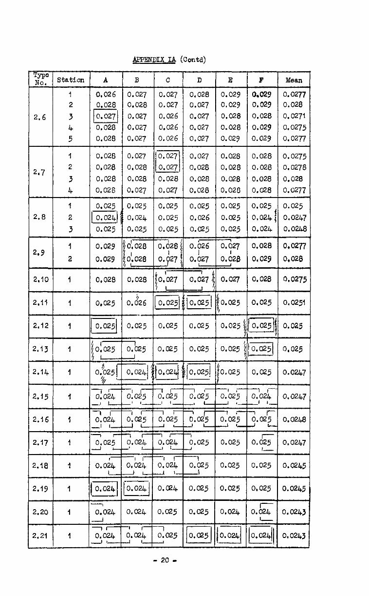
APPENDIX IA (Contd)
1
2.8 2
3
ti
I 2.9
2
2.10 1
2,12 I
2.13 I
2.14 I
2.15 1
2.16 I
2.17 1
2.18 1
2.19 I
2.20 1
+ 2.21 I
A
0.028
0.028
0.028
0.028
0.028
0.028
0.025
0.024)
0.025
0,029 0.029
0.028
0.025
,O!O25 I-
1 I- 0.024 _J L
-1 r 0.024 _I I- 7 I- 0.025 A L
0.0;; I--
-1 0.024
-1 0.024
--1 71 0.024
J'
B c 0.027 0.027 0.028 0.027
0.027 0.026
0.027 0.026
0.027 0.026
0.027 0.027
0.028 i 0.027
0.028 0.028
0.027 0.027
0.025 0.025
0.024 0.025
0.025 0.025
0'. 028 I
01.028
0.(1281
, 0.~27
0.028 ,o.‘cq i ‘,I
0.226 10.025) -. 0.025 0.025
1 o.o25 o.o25 -.J
r-1 01025 a&- _' ,_-I I_ ,-
I r1 0.02;
y?zd L
-I r-1 0.024 _! !.A O,b21 , 01026 _I c--J L
once4
o.a4 o.a25
r- 6.@24 &x5 -4 L-
- 20 -
D E
0.028 0.029 0.027 0.029
0.027 0.028
0.027 0.028
0.027 0.029
0.027 0.028
0.028 0.028
0.020 0.028
0.028 0.020
0.025
0.026
o.o25
0.p
0.027
+ 0.027; --I
0.0251
0.025 0.025 0.025 7 o.y27
0.026 6
0.027
0.025
0.025 0.025 I
0.025 0.025
0.025] 0.025
-1 i- 0.025
L r; r 5.025
-, 0.025 .J -1 0.025 -b
-7 ii-
0.025 2 c- -lr- 0.025
,-
0.025
0.025
0.025
0.025 c
-I o.ce5
0.025
0.024
T
0.024 -I
F
0.029 0.029 0.028
0.029
0.029
0.028 0.028
0.028
0.O7.8
0.025
0.024
0.024
Mean
0.0277
0.028 0.0271
0.0275
0.0277
0.0275
0.0278
0.028
0.0277
0.025
0.0247 0.02Lla
o.w7
0,028
0,028 0.0275
0.025 0.0251
0.025
0,025
0.0247
7 I_-- 0.024 -1 I- 7 o.& i c
0.05 ,--
0.0247
0.0248
0.0247
0.025 0.0245
0,025 0.0245
0.0243
0.0243
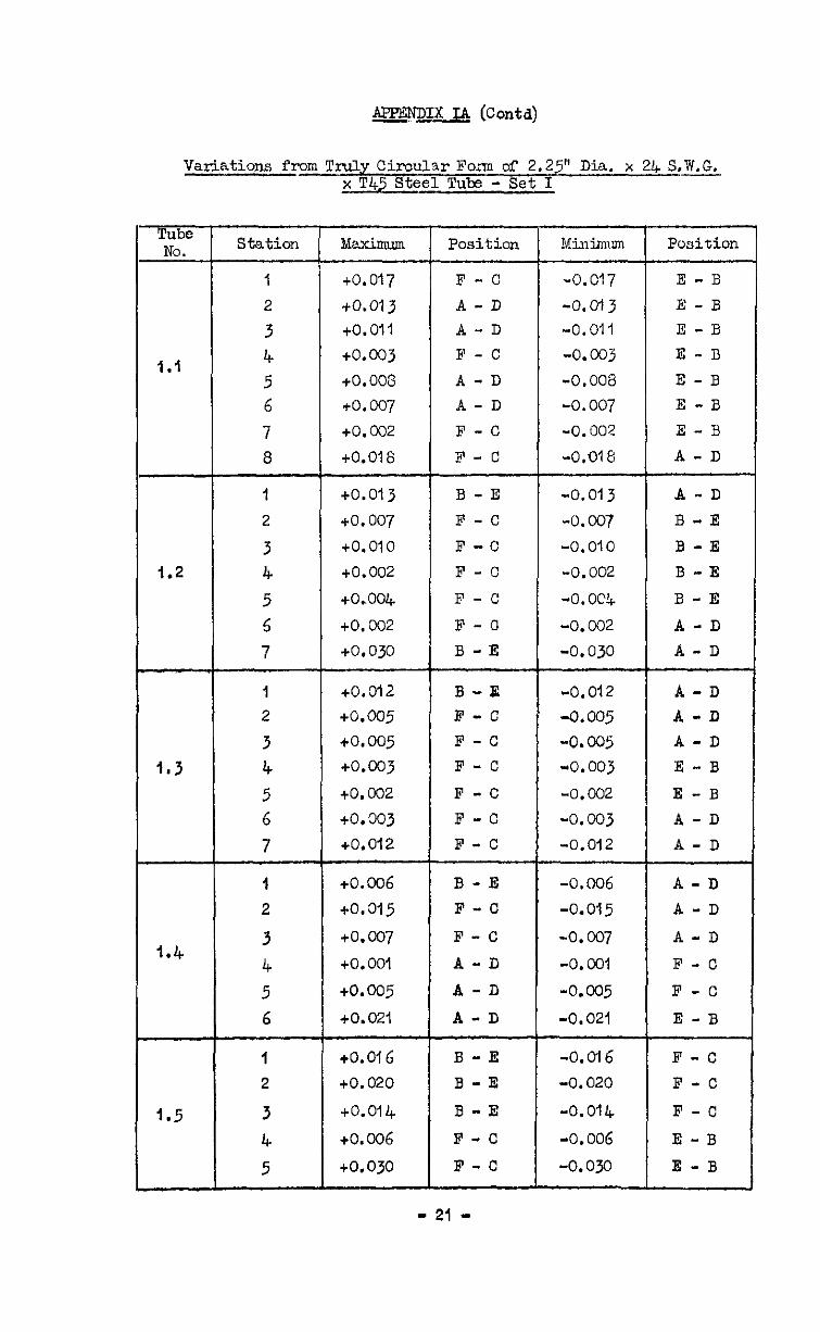
APFDDIX LA (Contd)
Varistions from Truly CirculsrFo,zn of 2.25" Dia. x 2!+ S.W.G. x T45 Steel Tube - Set I
Tube NO.
1.1
1.2
1.5
Station Maximum Position Minlirilum
1 to.017 F-C "0.017 2 +a013 A-D -o.G-t3 3 +O.Oll A-D -0.01 I
4 +0.003 F - c -0.003 5 +o. 008 A-D -0.008
6 to. 007 A-D -0.007 7 +o.c02 F-C -0.002
8 +0.018 F-C -0.016:
1
2
3 4 5 5
7
1
2
3 4 5 6
7
I
2
3 4 5 6
I
2
3 4
5
to.013
to. 007 to.010
to.002
to.004
to.002 to.030
-0.013 -0.007 -0.010
-0.002 -0. oc!k
-0.002 -0.030
to.012 to.005 to.005 to.wj
to.002 to.003 to.012
3-E
F -c
F -c
F-C
F -C
F-U
B -E
B-E F-C F -c F-C
F -C F -c
F-C
-0.012 A-D
-0.005 A-D
-0.005 A-D -0.003 E -B
-0.002 E -B -0.003 A-D -0.012 A-D
to.006 B-E -0.006 A-D to.315 F-C -0.015 A -D
to.cQ-/ F -c -0.007 A-D
to.001 A-D -0. COI F -c
to.005 A-D -0.005 F -c
to.021 A-D -0.021 E-B
to.01 6 B-E -0.0I6 F -C to. 020 B-E -0.020 F -c
to.014 B-E -0.014 F-c
tO.006 F -c -0.006 E-B
to.030 F-C -0.030 E-B
Position
E-B E-B E-B E -I3 E -B E -B E -B A -D
A "D B -E B-E
B -E
B-E
A -D A-D
- 21 -
APPENDIX IA (conta)
The Iii. Station Mexmm Position Mininnrm Position
1 +o. 009 F-C -0.009 A-D
2 +o.ooa E-B -0.008 A-D 1.6 3 +0.007 E-B -0.007 A-D
4 tO.coG E -B -0.006 A-D 5 to.014 F -C -0.014 A-D
1 to.004 F -c -0.004 E -B 2 to.003 A-D -0.003 E -B
4.7 3 to.003 A-D -0.003 E-B
4 to.007 F -c -0.007 E -B
- 22 -
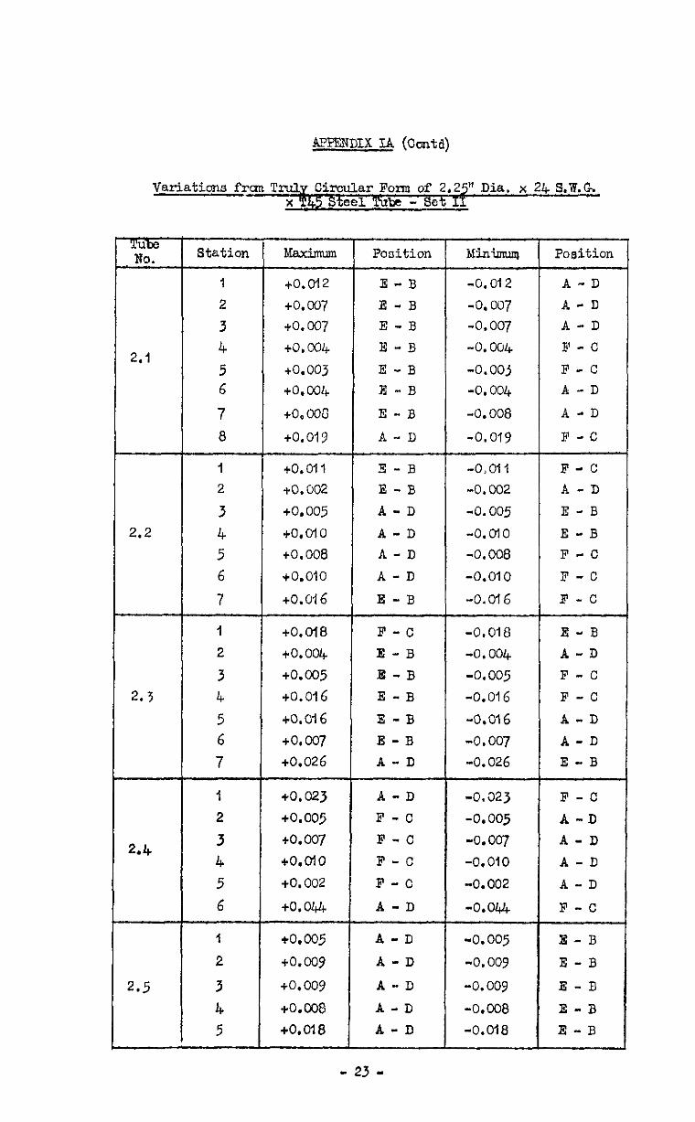
APPENDIX IA (Cuntd)
Variations frm 'Pm&y Circular Folm of 2,2$ Dia. x 24 S.W.G x r45 Steel Tube - 555
Tube No.
2.1
2.2
2.3
2.4
2.5
Station Maximum Position Minimuq
1 to.012 E-B -0.012
2 to.007 E -B -0.007
3 +a007 E -B -0.007
4 to.004 E-B -0.004
5 tO.OOJ E -B -0,ooj 6 to.004 E-B -0.004
7 +o.ooli E-B -0.008
8 to.019 A-D -0.019
I tO.oll 2 to. 002
3 to.005
4 to.oio
5 tO.008
6 to.010
7 to.016
E-B E-B A-D
A-D A-D
A-D
E -B
F-c E -B E-B
E-B
E-B E -B A-D
-0,oll
-0.002
-0.005
-0,olo
-0.008
-0.010
-0.016
1
2
3
4
5 6
7
I
2
3
4
5
6
1
2
3
4
5
tO.ol8
to.004
to.005
to.016
tO.016
to,co7 tO.026
-0.018
-0.004
-0.005
-0.016
-0.016
-0.007
-0.026
to, 023 A-D to.005 F -c
to.007 F -c to.olo F-C
+0.002 F -c
to.044 A -D
to.005 A-D
to.009 A-D
to.009 A-D
+o.ca A-D
+O.o-l8 A-D
-0.323
-0.005
-0.007
-0.010
-0.002
-O.O&
-0.005
-0.009
-0.009
-0.008
-0.018
Position
A-D
A-D A-D 3' - c
F-C A -D
A-D
F -c
F-C A -D
E-B
E -B F-C
F-C
F -C
E-B
A-D F-C
F -C
A-D
A-D E-B
F -C
A-D A -D
A-D
A-D
F -c
E-B
E -B
E -E
E-B E -B
- 23 -
APPENDIX IA (Coda)
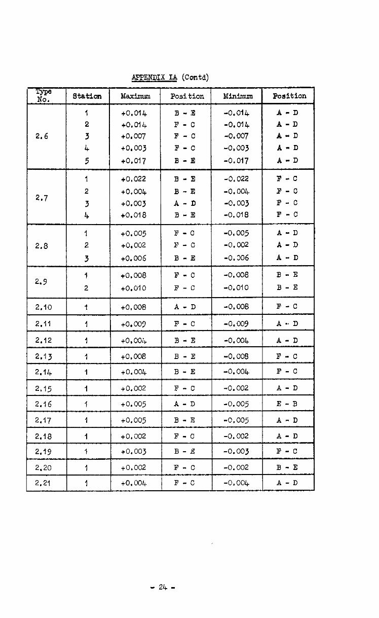
T NT station Maximum Position MinImum Position
I +0.014 B-E -0.014 A-D 2 co.014 F-O -0.014 A-D
2.6 3 +0.007 F -c -0.007 A-D 4 to.003 F -c -0,003 A-D
5 to.017 B -E -0.017 A-D
1 to.022 B -E -0.022 F-C 2
2.7 to.004 B-E -0.004 F-C
3 to.003 A-D -0.003 F-C 4 tO.018 B-E -0.018 F -c
- 24 -
AFFENDIX IA (Contd) --- I
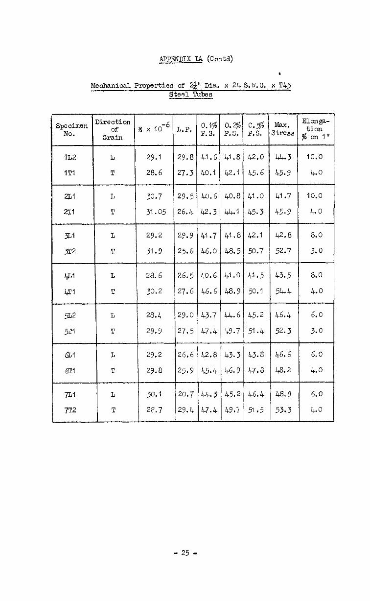
Mechanical Properties of 29" Dia. x 24 S.V.G. x T45 Steel Tubes -
L
T
L
T
L
T
L
T
L
T
L
T
30.7 29.5
31.05 26.J:.
29.2 20.9
31 .Y 25.6
28.6 26.5
30.2 27.6
20.1, 29.0
29.9 27.5
29.2 26.6
29.6 25.9
30.1 20.7
2P.7 29.4
40.6
12.3
40.6
46.6
43.7
47.4
42.8
45.4
44. 3
47.4
O.@ P.S.
41 .8
42.1
40.8
44.1
41.0
49.9
44.6
'bY.7
43.3
46.9
45.2
49-i
1
c.% Max. Elm@-
2,s. stress ti on $ on I"
42.0 44.3 10.0
45.6 45.9 4.0
41.0 41.7 10.0
45.3 45.? 4.0
42.1 42.8 8.0
50.7 52.7 3.0
41.5 43.5 8.0
50.1 54.4 4.0
45.2 46.4 6.0
51.4 52.3 3.0
43.8 46.6 6.0
Lb7.8 48.2 4.0
46.4 43.9 6.0
FL.5 53.3 4.0
- 25 -
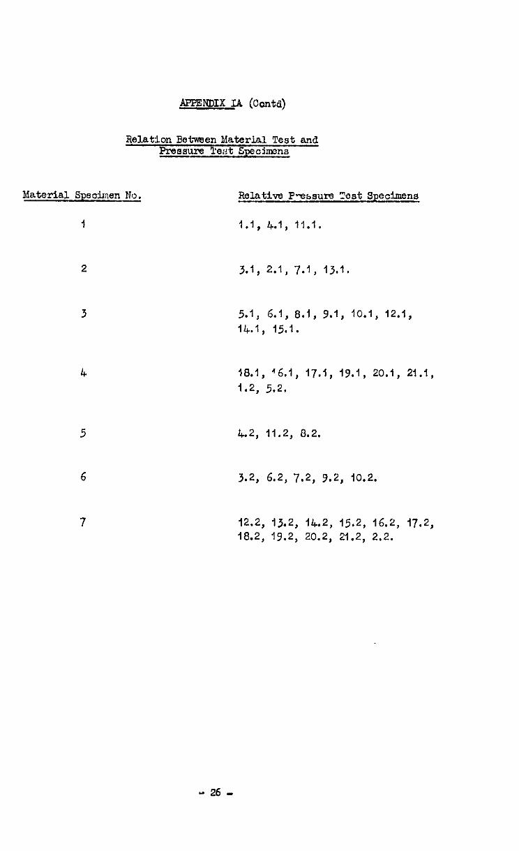
APPENrJIX IA (conta)
Relation Between Material Test and Pressure Test Speohens
Material Specitnen No.
I
Relative P-essum %st Specimens
1.1, 4.1, 11.1.
2 3.1, 2.1, 7.1, 13.1.
3 5.1, 6.1, 8.1, 9.1, 10.1, 12.1,
14.1, 15.1.
4 18.1, '6.1, 17.t, 19.1, 20.1, 21.1, 1.2, 5.2.
5 4.2, 11.2, 8.2.
6 3.2, 6.2, 7.2, 9.2, 10.2.
7 12.2, 13.2, 14.2, 15.2, 16.2, 17.2, 18.2, 19.2, 20.2, 21.2, 2.2.
- 26 -
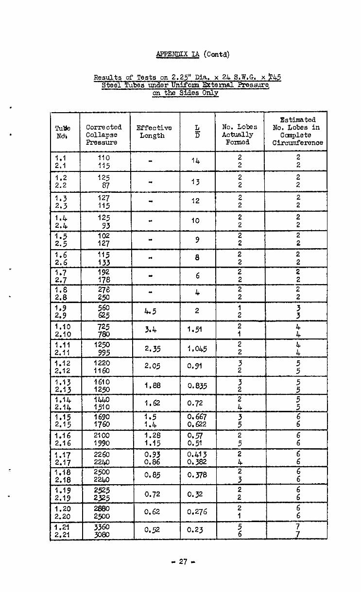
APPmDIx IA (conta)
Results of Tests on 2.25" Dia. x 24 S.W,G. x p45 Steel Tubes under Uniform External Pressure,
on the Sides Only
I
Estimated Tulle Corrected EfYective L No. Lobes No. Lobes in Ndb Collapse Length 5 Actually Canplete
PreSSUPS FOlTMd Ciroumference I
1.1 110 14
2 2 2.1 115 2 2
1.2 125 2 2 2.2 07 13 2 2
1.3 127 " 2.3 115
12 2 2 2 2
1.4 125 IO
2 2 2.4 93 2 2
1.5 102 2 2 2.5 127 9 2 2
- 27 -

Variation of Tube Thiclmess for 1.75” o/d :: '2.2 S.W.R. x T45 Steel Tubes Showirg Relation between Thiclmess
and Collapse Pattern - Set A
F xesn
0.031 0.030 0.031 0.030 0.030 0.0293 O.Ojl 0.0295 0.030 O.Qa3 0.031 0.0297 0.031 0.03 O.Ojl 0.03
Tube No. :tatior. A B
Al
0.031 0.031 0.031 0.031 0.034 0.031 0.031 0.031
0.030 0.030 0.030 0.030 0.030 0.029 0.030 0.030
A2
0.028 0.029 0.028 0. 0.028 0.028 0.028 0.028 0.028 0.028 0.028 0.028 0.028 0.028
c D
0.029 0.029 0.029 0.029
---I--
0.028 0.028 0.028 0.028 0.028 0.028 0.028 0.029 0.028 0.029 0.028 0.029
0.030 0.031
t
0.030 0.031 0.029 0.030 0.029 0.030 0.029 0.030 0.029 0.030 0.030 0.031
3
0.030 0. ojo 0.029 0.029 0.029 0.030 0.030 0.030
0.030 0.030 0.030 0. op 0.030 0.030 0.033
0.030 0.031 0.031 0.031 0.031 0.031
0.030 0.029 0.030 0.029 0.029
0.031 0.031 0.031 0.031
0.030 0.031 O.031
i- 0.029
0.031
0.030
0.029 0.029 0.029 0.029 0.029 0.029 0.029
0.09 0.029 0.029 0.030 0.030 0.030
0.0293 0.0293 0.029 0.029 0.029 0.029 0.0293
0.03 0.0301 0.0303 0.0301 0.0301 0.0305
0.0298 0.0298 0.0301 0.030 0.030
0.0298 0.03 0.0301 0.03
0.029 0.030 0.030 0.029 0.029 0.030
0. ojo 0.031 0.030 0.031 0.031
0.031 0.031 0.031 0.03l 0.031 0.032 0.031 0.032 0.033 0.031 0.031 0.031
0.029 0.029 0.029 0.02 d 0.029 0.030
0.029 0.030 0.050 0.030 0. ojo
A3
0.029 0.029 0.029 0.029 0.029
0.030 0.031 0.030 0.030 0.031 0.031 0.031 0.030' 0.031 0.030
4.5
A6
0.02 4 0.0 9
0.q 0.029
0.030 0.030 0.029
p.030 0.031 I 0.030 0.031
0.030 0.030 0.030 0.030
0.028 0.029' 0.029 0.029
0.030 0.029 0.029
I 2
;:
I 2 3
0.030; 0.031 I 0.030 0.031
0.030 0.030 0.030
0.0303 0.0305 0.0303
0.031 0.031 0.031: 0.032 0.0311 0.032
A7 1 0.031 0.031 0.030 0.0291 0.030
0.030 A8 :o.o2si 0.030, 0.03 1
+ 3.031 0.031
0.0301
‘3.029j 1.029: 3.0298 A9
- 28 -

J$ETENDIX IB (Contd)
Variations in CFrculsrity of 1.75" din. x 2.2 S.W.R. x T.42 Steel Tubes - Set G
Dimensions Show Xsxinnun and Xinimm Variations from Tru3.y Cirmlsr Fork inThousandths d w Inoh
Pube No. Max. Pos. 1a.n. Pos.
Gl +o. 005 C/F -0.016 AB/!IX : +o. +o. 003 CO2 B/E -0. -0.008 co5 E/&S WhA
4 +o.ooj E - -0.005 (w- 2 +o.o07 O-F -0.011 DE/m
+o.oo6 BG,'EF -0.008 CDfiA
z +o. to. 003 003 E-E -0.006 -0.005 cD/Fn C-F 9 +o. 002 FY$ -o.oc& B-E
IO +o. 001 F-L -0.004 B-E II +o. CO2 h-D -0.005 Ex@F 12 +o. 003 C-F -0. co5 DE/m :1: +o. 002 AE/DE -0.006 EC/&F
+o. oc2 B-E -0.005 A-D
:z +0.002 Ec/EF -0.005 A-D to.004 -0.008 c-F
17 to. 002 &L -0.004 B-E 18 +o.oo2 E-ii -0.006 B-E 19 to.003 - -0.005 - 20 to.003 c&L -0.007 AgiE
21 to. 004 B-E -0.006 WJ?A 22 +o. 002 B-E -0.004 C-F 23 to.003 B-E -0.007 C-F l'; to.002 A-D -0.003 -
+O.OlO B-E -0.008 :A 26 to. Cd3 a@ -0.003 wm 27 co.003 A$& - -0.003 C-F 28 to.006
i&C@5 ca/EA tO.CU+ A-D
Details of Dqe observed to 1.75” Dia. x 22 S.W.R. x T.45 Tubes
Tube No. Details
Al Al A3 B2 G6
Slight bruise between stations 3-4 at position C-D Sdl cut betwem stations 6-7 at position F-A Bruise between stations 5-6 at position J-C Bruise between stations 3-4 at position E-A Bruise at end at position C
- 37 -
AE'PENDIX IB (h&d)
Tube No. Station A B C D E F xean
1 0.027 0.027 0.028 0.029 0.030 0.029 0.0283
: 0.028 0.029 0.029 0.028 0.028 0.028 0.029 0.029 0.030 0.029 0.030 0.030 0.0288 0.029 Cl 4 0.029 0.029 0.029 0.028 0.026 0.029 0.0287
2 0.030 0.029 0.030 0.030 0.029 0.029 0.028 0.028 0.027 0.02s 0.029 0.028 0.029 0.0285 7 0.029 0.030 0.029 0.028 0.027 0.027 0.0283 a 0.028 0.030 0.031 0.034 0.028 0.027 0.029
c2
1 0.028 0.027 0.028 0.029 0.030 0.030 0.0287
: 0.029 0.028 0.027 0.02 0.C27 0.027 0.028 0.027 0.030 0.029 I. 0.028
0.030 0.030 0.0283 0.0283 4 0.02s 0 02 0.028 0.027 0.029 0.0285 5 0.030 0.030 0.029 0.077 0.028 0.029 0.0288 6 0.029 0.029 0.029 0.028 0.028 0.028 0.0285 7 0.029 0.030 0.030 0.029 0.028 0.028 0.029
03
clc
05
c6
07
ca
CY
1 0.030 0.031 3.029 0.027 0.026 0.027 0.0283 2 0.029 0.030 0.030 0.028 0.026 0.026 0.0281 l 0.027 0.029 0.030 0.029 jO.02 0.026; 0.028
0.027 0.028 0.030 0.030 :0.02 0.0283 5 0.025 0.028 0.03l 0.030 @.02
0.027; 0.025: 0.0277
6 0.026 0.028 0.030 0.030 0.028 0.026 0.028
1 0.031 0.030 0.0281 0.026 0.027 0.029 0.0285
: 0.029 ':O.oZa 0.028 0.028,, 0.027 0.330 lo.02a qi 0.028 0.027: 0.027
0.028 0.028
4 0.028 jO.027 0.027 0.028; 0.029 0.029 0.0284 0.029 0.028
5 0.028 '0.027 0.02 0.028 0.029 0.029 0.028
1 0.030 0.030 0.029 0.028 0.028 0.029 0.029 ; 0.03? 0.030 0.029 ;'0.027 0.027 0.029?
0.030 0.030 0.029 ;,O.O28 0.027 0.02ai 0.0288 0.0287
4 0.029 0.030 0.030 0.029 0.027 0.028 0.0288
1 0.027 0.027 0.028 0.029 0.029 : 0.028; O.C27[]0.02@
0.029 0.0281 0.029 0.030 0.030 0.0287
0.029 0.027 0.027 0.028 0.030 0.031 0.0287
1 0.039 0.030 0.028 0.028 m 0.030 0.0295
1 0.031 0.034 0.030 [0.029[]0.029 iO.029 0.0298
1 ]0.029[~0.030 0.031 0.031 0.030 0.028[ 0.0298
Variation of Tube Thickness for 1.75" o/d x 22 S.W.R. x T45 Steel Tubes Showing Relation between Thickness
and Collapse Pattern - Set C
- 30 -
Variation of Tube Thickness for 1.75" o/d x 22 s.v.8. X T45 Steel Tubes Showirg Relation bctwsen Thickness
and Colla~sc Pattarn - Set F
Tube No. A B C D E F dean
Fl F2 F3 F4 F5 F6
i% FY FlO Fll F12
0.0298 0.029t 0.0295 0.0293 0.0293 0.0293 0.0295 0.0297 0.0295 0.0293 0.0291 0.0291
- 31 -
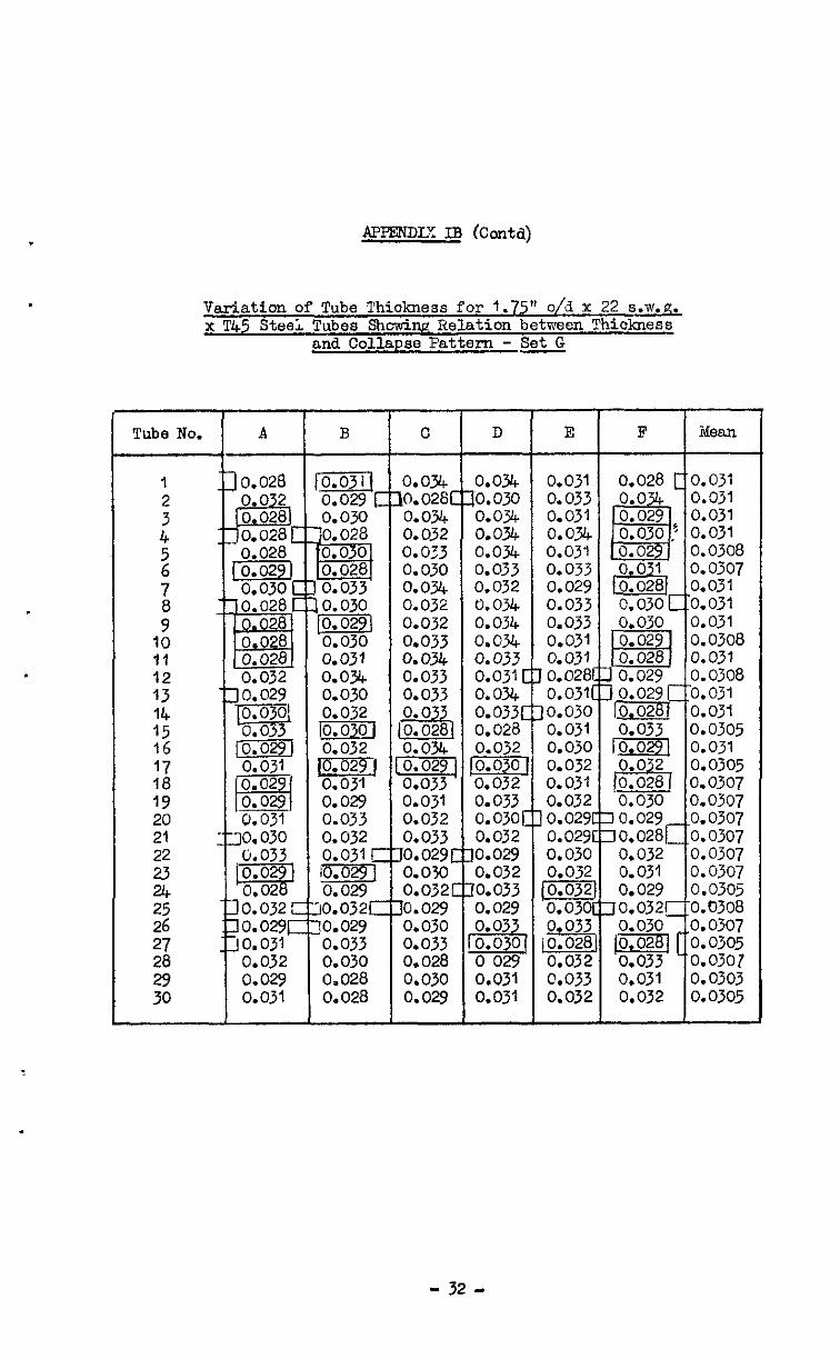
Variation of Tube Thiolmess for 1.75" o/it x 22 s.w.g. x T45 Steei Tubes Shdw Relation between 1 hickness
and Collapse Pattern - Set G
- 32 -
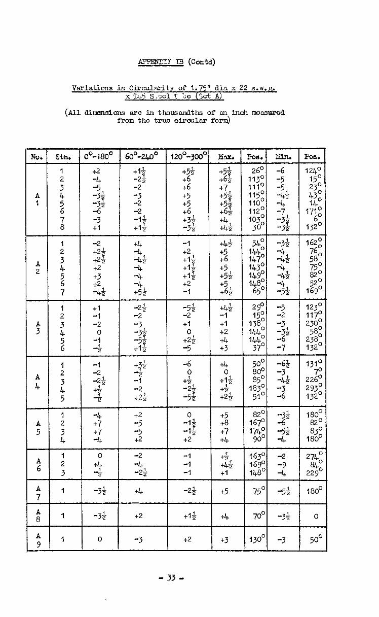
A?FRCXY I3 (Con@
Variaticns jn Circulzity of 1.75" din x 22 s.w.p. x Tq.5 s ,sel " ::e (Set A)
(AllakIrzlsim mx inthol.E%nndths ofal inohltxxssurcd from the true circular form)
NO. Stn. 00" l8O0 1 6o"-240' 120°-3coo1 tlu. 1 h4.t -n. I 2o"-3cO" tlu. 3Js. -n.
t54 +54 t5+ +61 +5+ +61
26O 26O -6 -6 +6 +6 1130 1130 -5 -5 t6 4.6 +7 +7 1110 1110
1150 1150 -5 -5
+5 +5 +5$ +5$ -45 -45 +5 +5 +6 +6
+57 +57 IIOO -4 IIOO -4 t6s t6s 1120 1120 -7 -7
+3$ +3$ +4 +4 1030 1030 -32 -32 -hb& -hb& 30" 30"
I;$ I;$ 2 2
-1 -1 +4+ +4+ -3h -3h +2 +2 +5 +5
54: 54:
:go :go 143O 143O
1;; 1;;
WY0 WY0 -4 -4
: : +2 +2 +5 +5 148' z- 148' z- -1 -1 t6; t6; 65' 65' -5s -5s
ma.
I 24O
132~
162;
760 58
0
E" 52"
169'
1 +2 +I" : 1; -2 -21
A 1 i -34 zi5 z;
-2 z -3
+I -I$ +I5
1 -2 +4
: +21 ? A 4
+2q & 2 +2 5 +3 1;
6 +2 4
123O 1170 230°
58' 238O 132O
3 I iL I 0 I -34
1310 70
226' 293' 132O
-6 +4 5o" -6% 0 0 80' -3
+& +I& 85' -4; -2; +& 183' -3 -5s t2$ 51' -6
+2 +2 -5 -5
2 2
A :
ti 5
t t7
4 -4 H-i-- 1 0 A 2 6 3
+4 :;
4 -2;
180' 82O 83'
180'
0 t5 0
-I$ :
+8 ,;;o z-
-1s +7 1740 -5; +2 +4 9o” -4
274' a0
229O
-1 +& 163~ -2 -1 i-44. 1690 -9 -1 +I 148' -4
-26 1 t5 I 7501 -5; 180'
+I$ 1 t4 ) 7001 -3& 0 A I 8 -3$ t2
A 9 1
0 -3 +2 j +3 II3001 -3 5o"
- 33 -
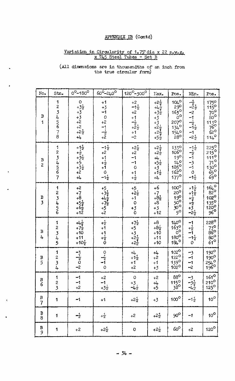
Variation in CinxA3.rit.v of 1.751d3.a x 22 s.w.~ x T45 Steel Tubes - Set B
(All dimensions are in thousndths of en inch fYom the true circular form)
. - POS. - 1750 115c
c
3 113;
‘6; 0
1140
No. Pos.
1040 290
10;
207~ 134O 1540 280
o"-180' 6oo-2400
+I +3 -1 0
+2 -1 -$
+2
,20°-300~
+2 -I& +2 +I L 2, +2q
+I -2
I lax.
+21 T +47 +3F 13 +3 +2-L
? +2- a +5?
Ein.
4 -23 -2
? :; -1 -2g
0 +3i- +3 +3 +2 +2 +2$ +4
-1; +2 +I t$ t-l
0 -I&
t21 ? +25 +4 +5& +3 +I$ +4
t6 +7 t8& t8 +3 +I2
+8 t8+ +I0 +I1 +I0
1330 106~
0
::o 1850 j62O 177O
1000 200 190 5o” 3o"
go
225c 215c lllC 71C
130;
$0
+I1 12
*Z? +3& +5 +33
2
+2 +7 +a '53 t61 +I2
z+
-i -3 -1
0 -1%
+I' 7
+1-g tL
B +S +3
2' -2
-1 tg -1 -I&
0
t2$ t2 -1 -1 0
+I +$
+5 +23 +I 0
+3 0
+7$ +5 +3 +21 7 +25
B 2
- IfhO
82' 1020 135O 1200
9@
+5 ‘3#
I$$ +5 t2
t& +I +I t$
0
B 3
+4$ +72 t10 +I1 +lO$
0
:i$
180' m"
228'
z$
61'
B 4
B 5
-3 4 0
-2
0 7
-’ 0
+4 +I& 4-l t2
t4 t2 +I +3
102O 122O 1390 1020
-3 192' -1 190' -1 P&O -2 1960
I3 6
1
:
-1 -1 t2
2 +5
88O 1150
38'
161' ?lOO 125~ -
IO0
t2 -1 t3&
cl
0 +3 -4h
+2& B 7
t3 ICOO -1
4 B 8
-
B 9
t+ +2 +23 90” -1 IO0
t2 t2& 0 t2+ 60’ +2 1200
- 34 -
AFJPENDIX It3 (conta)
variations in circularity of 1.75" &La x 22 8.W.R. x T45 Steel !Tube - Set C
(Allailmnsions are in thousmaths Jfaninohfrari the true cdxcular form)
lo. stn. 00-1800
I -24
: =2 c 4 +21 1 2 +% ?
+3
z 2
1 0 2 +$
c 3 +4 2 '; +4
+I' 6 +I= ?
7 +56
I 2 -2'25 -4+
c 3 z
-2 +7J- 5 +5H ?
6 -14
1 -2
: 2
;f. 4 -1
4 5 -2
I +I C 2 +23 5 ;I -1
0
"6 I -8
; :
C 7 ' +I
c I 8 +3
c 9 1 -3
+I 0
-1 +2 +& -1 +2; +2
+5& +4 c2; +2 +2 33 0 0
+6$ +4 +5 +21 +3; "7 +3g +4
+& +5 +5$- +I +4 +4 0
+$ +I& +4$ +I +4
+I& A$ +2' -1 +4 ?
+45 -13 +9 +I0
-2 0 +I$ -1 -I$ 0 4 0 :p
-3 -2 -5 +7$
+5-s 0 +8 +I1
+43 -6 -6 -4 t8;
+J+ 2 +; +9
+4 I +4 1 +3&
98” -3% I&~ -2 173O 153;
-I$ +l-
;go l2 +1
9g a -1
117 -1 1200 0 15O
:z" 20;
4 -13
+I -1 151° -14
120;
z"
2
26' 138'
0 1
:z” -g lco0 -1 lo8° 0
5o" +I
900 -4 I
so01 -3
I Pos.
1660 600
IZJ 84:
230' uc3O
180' 149O 140° 85' l;:O 0
23@ 13%
:z" 232O
- 35 -
APEmIx IB (o&d)
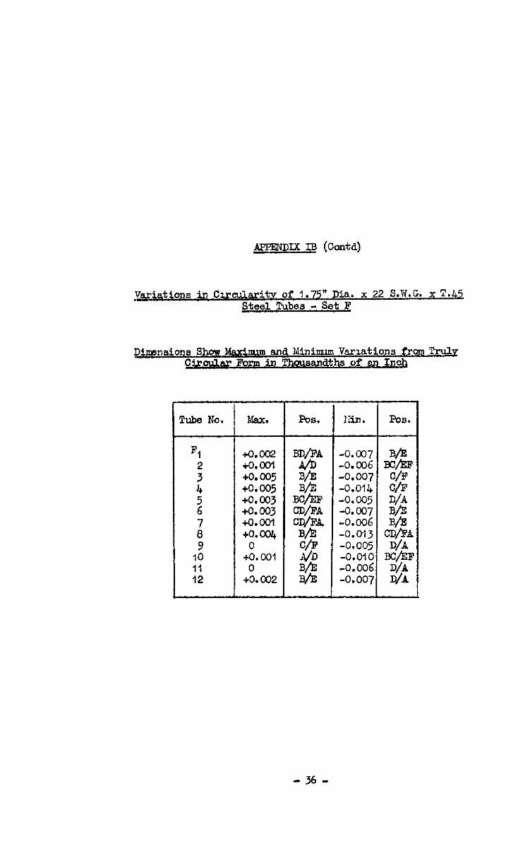
&j&$ons in Cmcular'tv of 1.75" Dia. x 22 S.B.G. x T.45 St&. Tubes - set F
Dimensione Shm kcirm.m and Minimm Variations from Truly C&&ar Form in Thousandths of an Inch
Pube No.
Fl
; 4
2
8' 9
IO II 12
Nsx.
+o.cGz +o. COI +o.m5 +0.005 +o.cQ3 +0.003 +O.oOl +o. co4 0
+O.ool 0
+o. co2
PCS. Eiin.
-0.007 -0.CQ6 -0.007 -O.Oll+ -0.005 -0.007 -0.006 -0.013 -0.005 -0.OlC -0.~~2.6 -0.007
- 36 -
J$ETENDIX IB (Contd)
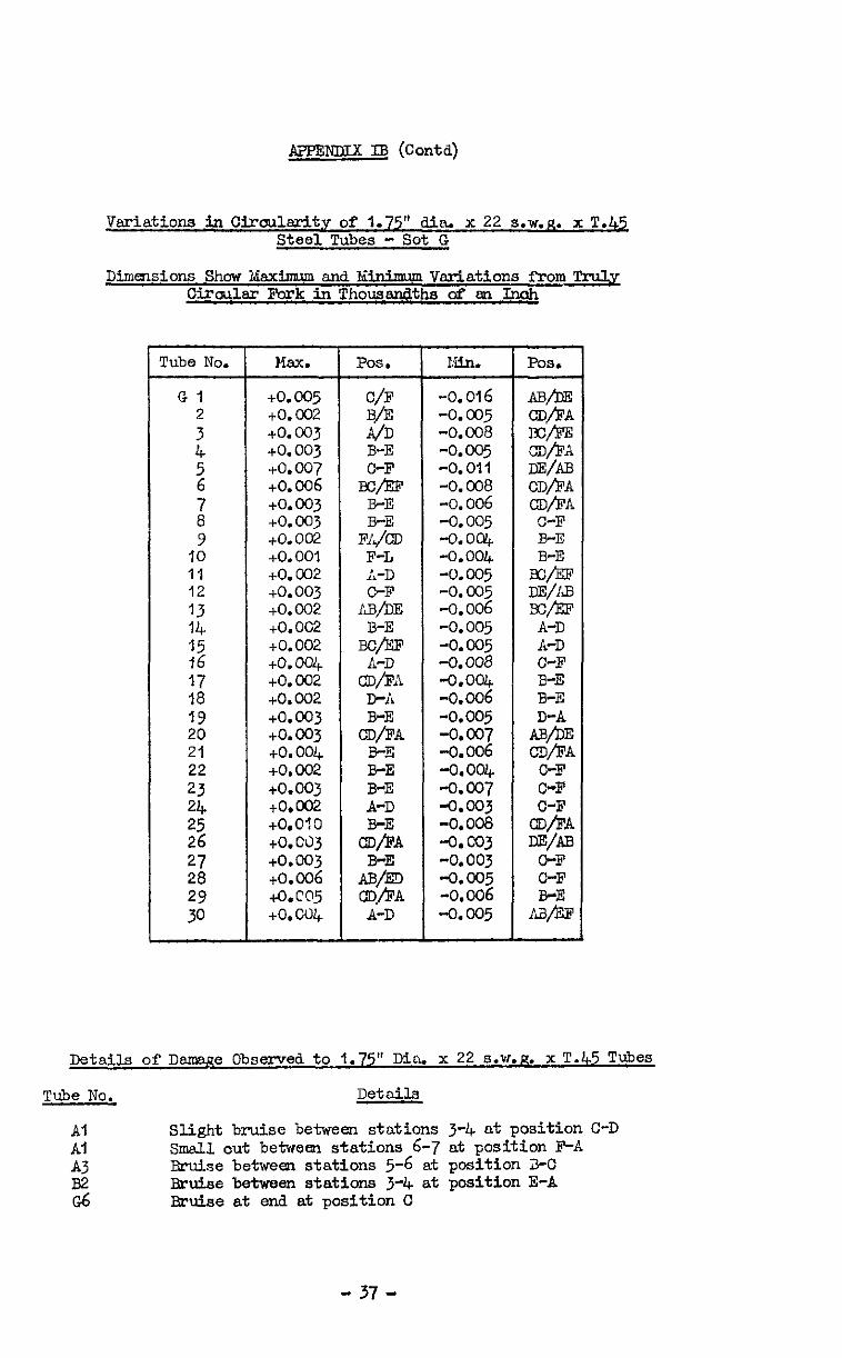
Variations in CFrculsrity of 1.75" din. x 2.2 S.W.R. x T.42 Steel Tubes - Set G
Dimensions Show Xsxinnun and Xinimm Variations from Tru3.y Cirmlsr Fork inThousandths d w Inoh
Pube No. Max. Pos. 1a.n. Pos.
Gl +o. 005 C/F -0.016 AB/!IX : +o. +o. 003 CO2 B/E -0. -0.008 co5 E/&S WhA
4 +o.ooj E - -0.005 (w- 2 +o.o07 O-F -0.011 DE/m
+o.oo6 BG,'EF -0.008 CDfiA
z +o. to. 003 003 E-E -0.006 -0.005 cD/Fn C-F 9 +o. 002 FY$ -o.oc& B-E
IO +o. 001 F-L -0.004 B-E II +o. CO2 h-D -0.005 Ex@F 12 +o. 003 C-F -0. co5 DE/m :1: +o. 002 AE/DE -0.006 EC/&F
+o. oc2 B-E -0.005 A-D
:z +0.002 Ec/EF -0.005 A-D to.004 -0.008 c-F
17 to. 002 &L -0.004 B-E 18 +o.oo2 E-ii -0.006 B-E 19 to.003 - -0.005 - 20 to.003 c&L -0.007 AgiE
21 to. 004 B-E -0.006 WJ?A 22 +o. 002 B-E -0.004 C-F 23 to.003 B-E -0.007 C-F l'; to.002 A-D -0.003 -
+O.OlO B-E -0.008 :A 26 to. Cd3 a@ -0.003 wm 27 co.003 A$& - -0.003 C-F 28 to.006
i&C@5 ca/EA tO.CU+ A-D
Details of Dqe observed to 1.75” Dia. x 22 S.W.R. x T.45 Tubes
Tube No. Details
Al Al A3 B2 G6
Slight bruise between stations 3-4 at position C-D Sdl cut betwem stations 6-7 at position F-A Bruise between stations 5-6 at position J-C Bruise between stations 3-4 at position E-A Bruise at end at position C
- 37 -

Meohsnicsl Prouerties of I$" dia. x 22 8.w.g. x T45 Steel Tubes
Specimen Direction x Yo-6 L*p* I3 Ps Ps
0.1% 0.270 0.5% l&cc. NO. of Grain I StF3SS
bF1 :
29.9 32.3
T 4=
: :;*'; JO:2
27.1 43.4 17.5 45.1 29.5 46.7
20.6 42.1
t
22.f 42.6 30.3 43.3 15.5 42.0
27.9 42.7 ,27.7 43.8
23.0 42.0
40.4 40.7 44.4 47.5
$2 ';Bd: 4319 45:s
45.2
$2
$2 . 51.2
Z:i 49.0
91 L 32.2 23.3 50.7 52.0 52.7 53.3 T 31.1 23.6 45.8 48.5 51.7 54.3
6El L 28.6 29.5 42.9 43.7 44.2 46.5
44.3 46.4 T 31.6 25.5 49.2 53.0
m L 30.2 26.4 44.9 45.4 46.0 50.7
ml L 30.6 31.3 47.8 48.4 48.8 52.7 T 28.7 21.6 47.3 43.9 47.1 54.1
suff%iEl~enotes Specimen fYomOnsXnd of Origind Tube II F.J I, 1, II ()thar I, I, It II 11 M 0 11 11 ta&y& I, !I II
L indicates Longitudinal test result
T i.nd.ioates Transverse test result
Elongation $ on 1"
;:"o 9.0
11.0 7.0
11.0 7.0
13.0 6.0
12.0
::: 12.0"
.
6.0 4.0
12.0 8.0
11.0
11.0 7.0
Location of Sveoimcns Relative to Sets of Test Specimen
set No. Specimen Set Number
- 38 -
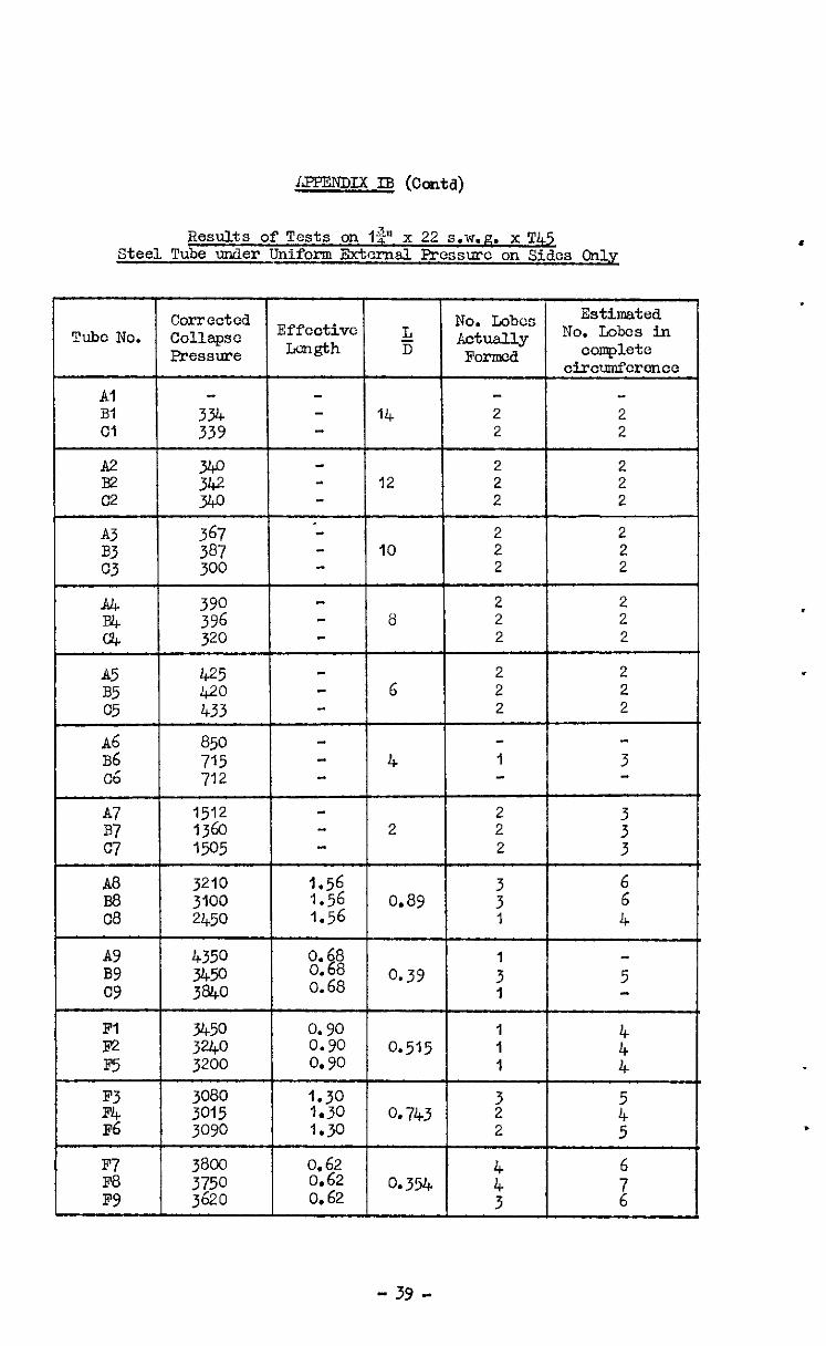
LFPENDIX IB (Cc&d)
Results of Tests on I$" x 22 S.W.R. x Tl& Steel Tube under Uniform External Fressmc on Sides Only
Corrected No. Lobes Estimated Tube No. COllapSC Effcctivc L No. Lobes in
Pressure mgth iT Actually F0noca complete
circumfcrencc
Al Bi :TG 14 2 2 Cl 2 2
A2 2 2 B2 12 2 2 c2
z?$
2 2
A3 B3
$3: 2 2 10 2 2
c3 3oo 2 2
A4 B4
:'9: 2 2 8 2 2
cs 320 2 2
A5 425 2 2 B5 420 6 2 2 c5 433 2 2
A6 850 ~6 715 4 1 3 c6 712
A7 1512 2 B7 1360 2 2 : C7 1505 2 3
A8 3210 1.56 6 Ba 3100 1.56 0.89
: 6
c8 2450 1.56 I 4
A9 4350 0.68 BY 3450 0.68 0.68
0.39 : 5 CY 38bo 1
2 3450 3240 0.90 0.90 0.515 1 1 4" F5 3200 0.90 1 4
:.l 3015 3080 1.30 1.30 0.743 z ~6
: 3090 I.30 2 5
E-7 3800 0.62 4 6 F-8 PY
;?g 0.62 0.354 4 0 0.62 3 i
- 39 -
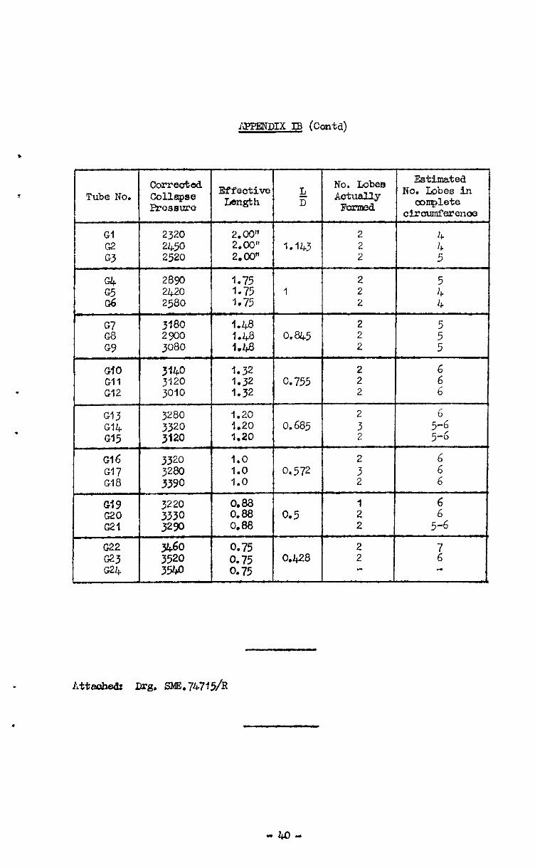
mPEND1x I8 (conta)
.
Correuted No. Lobee Estimatea
Tube NO. Collapse Effectim & Actually No. Lobes in Prosem Length D mmplete
CticwnferenW
Gl 2320 2.00" 2 G2 2450 2.00" 1.143 2 :: G3 2520 2.00" 2 5
28Y-J 1.75 2 2420 1.75 1 2 I’, 2580 1.75 2 4
2 2900 3180 1.48 1.48 0.845 2 2 5’ GY 3080 1.48 2 5
Gl3 3280 1.20 2 G14 Ol5 ;:z:: 1.20 0.685 :
5"6 1.20 5-G
GIG 3320 1.0 2 6
Gi7 3280 1.0 0.572 3 Gl8 3390 1.0 2 z
Gl9 3220 0.88 z’: 5:$ 0.88 0.88 0.5
: 2 2 5-6
G22 go” 0.75 2 G23 0.75 0.428 2 l c24 3w 0.75
Atteaheds Drg. SML747f5/R


.
AF'FENDIX IC
Variation in Tube !Chicknoss for I" dia. x 24 S.W.G. x l'45, Steel Tubes Showing Relation Between Wall 'l'hipkness
and Collapse Pattern - Set 1
Tube No.
1
2
3
4
5
6
7
8
9
10
11
12
Station
1
: 4
1
:
1
:
1
1
1
A B C D E F
0.025 0.025 0.024 0.023 0.023 0.024 11 11 ,, !I 11 !I II II ,t II C.024 0.025 I, It 11 0.024 8, 0.024
0.025 0.025 0.024 0.023 0.023 0.024 0.025 0.025 0.024 0.023 0.024 0.024 0.025 0.025 0.025 0.024 0.024 0.024
0.023 0.023 0.024 0.025 0.025 0.024 0.023 0.023 0.024 0.025 0.025 0.024 0.024 0.023 0.024 0.025 0.025 0.025
0.024 0.023 0.023 0.024 0.024
0.024
--P !i$
o.o&
10.024
:o.og
,0.023
0.023
---I 0.023
-f a3 ---JT
a233 ij
0.026)
3 0.025
O&C I I-
0.02g
0.024
0.0;3
g
3
0.022
0.024
aA -"-'3
0.024
0.05
O.o& 4 L
o.oti
s.
0.024
?=
0.024
0.+4
‘O.@
0.024
10.024 0.024
Mea2
0.024 0.024 0.0243 0.0242
0.024 0.0242 0.0245
0.024 0.024 0.0243
0.0237
0.0237
0.0237
0.0237
0.0238
0.0238
0.0238
0.024
0.024
* 41 -
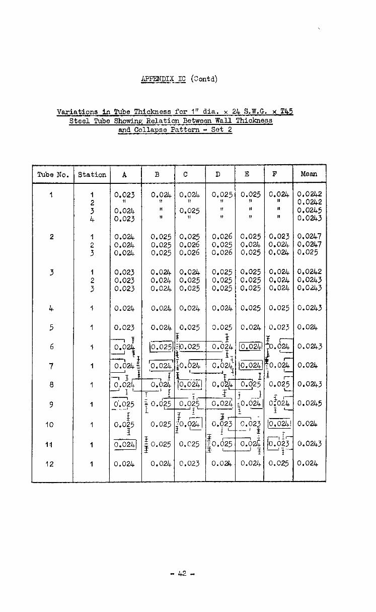
UPENDIX IC (Contd) ISPENDIX IC (Contd) - - -- --- -- ---
Variations In Tube Thickness for I" dia.4 S.W.G. x 'I!42 Variations In Tube Thickness for I" dia.4 S.W.G. x 'I!42 Steel Tube Showincc Relation Between Wall Thickness Steel Tube Showincc Relation Between Wall Thickness -- --
end Collapse Pattern - Set 2 end Collapse Pattern - Set 2
Rice No.
1
2
3
4
5
6
7
8
9
IO
Id
12
3tation
:
it
1
:
1
:
1
1
I
1
1
1
1
1
1
L
A
0.023 II 0.024 0.023
0.024 I,
0.025 II
0.025 0.025 0.024 1, 11 II II II 0, ,, 1, ,,
0.0242 0.0242 0.0245 0.0243 0.024 0.025 0.025 0.026 0.025 0.023 0.0247 0.024 0.025 0.026 0.025 0.024 0.024 0.0247 0.024 0.025 0.026 0.026 0.025 0.024 0.025
0.023 0.02% 0.024 0.025 0.025 0.024 0.0242 0.023 0.024 0.025 0.025 0.025 0.024 0.0243 0.023 0.024 0.025 0.025 0.025 0.024 O.O&3
0.024 0.024 0.024 0.024 0.025 0.025
0.023 0.024 0.025 0.024
(0.025 0.0241
0.025
0.5
-.- 0.0241 ---
- f,- y??- r t
Log]
0.025
-i Ode24
-A 0.024
0.024 -I 3?--
0.023 I f' ;o.oz
-
0.024
0.024 I
a25 1
0.63
0.0243
0.024
o.oz+3
0.024
0.0243
0.0245
- - 0.023 .-I * --Ii 0.024 -Ji
0.024
0.024
E 0.025 E
o.C25 0.0243
0.024 0.024 0.023 0.025 0.024
B C D E F Mean
- 42 -
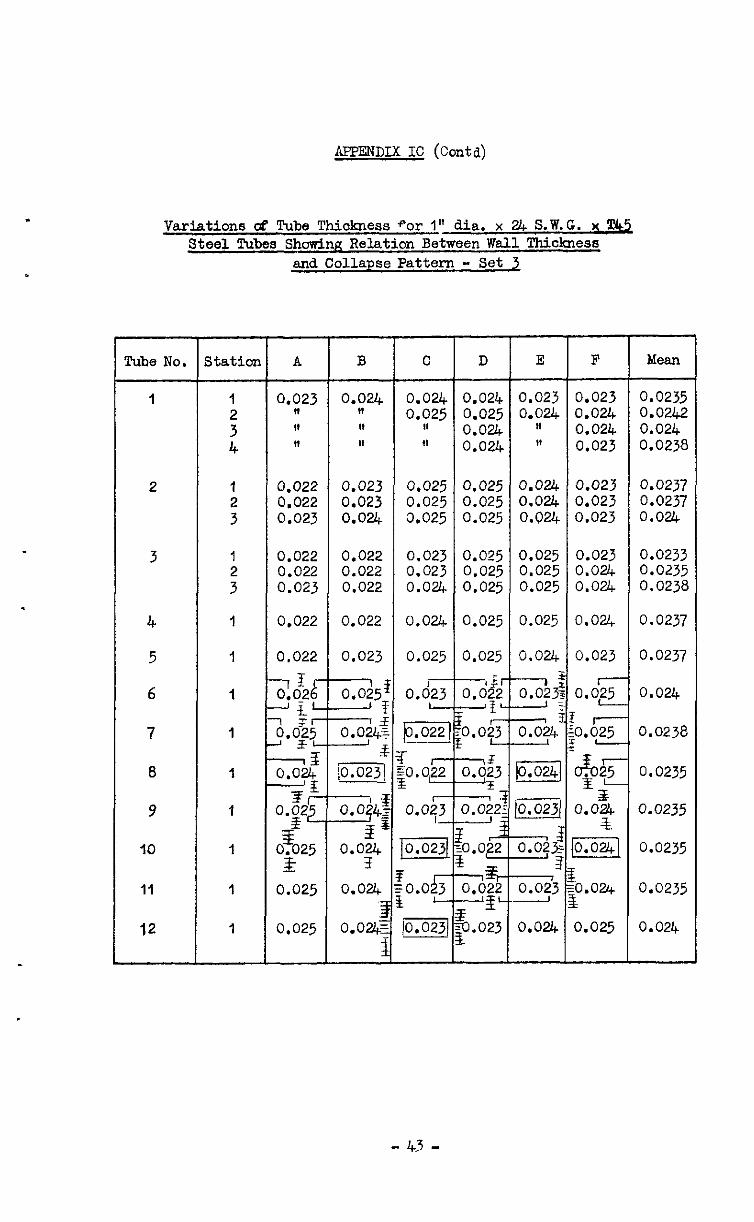
UPENDIX IC (Contd)
Varjations ck Tube Thickness *or I" dia. x 24 S.W.G. x &!j. Steel Tubes Showing Relation Between Wall Thickness
and Collapse Pattern - Set 2
l'uhe No. Station A B C D E F Mean
1 1 0.023 0.024 o.oZ+ 0.024 0.023 0.023 0.0235
: II It ,, II 0.025 81 0.024 0.025 0.024 I4 O.Our. 0.024 0.0242 0.024 4 11 II et 0.024 It 0.023 0.0238
2
3
4
5
6
7
8
9
IO
11
12
I
1
1
1
1
1 1 0.025 / 0.0247 mp.OzJI 0.024/ 0.025 1 0.02lb
0.0237 0.0237 0.024
0.0233 0.0235 0.0238
0.0237
0.0237
0.024
0.0238
0.0235
0.0235
0.0235
0.0235
- 43 -
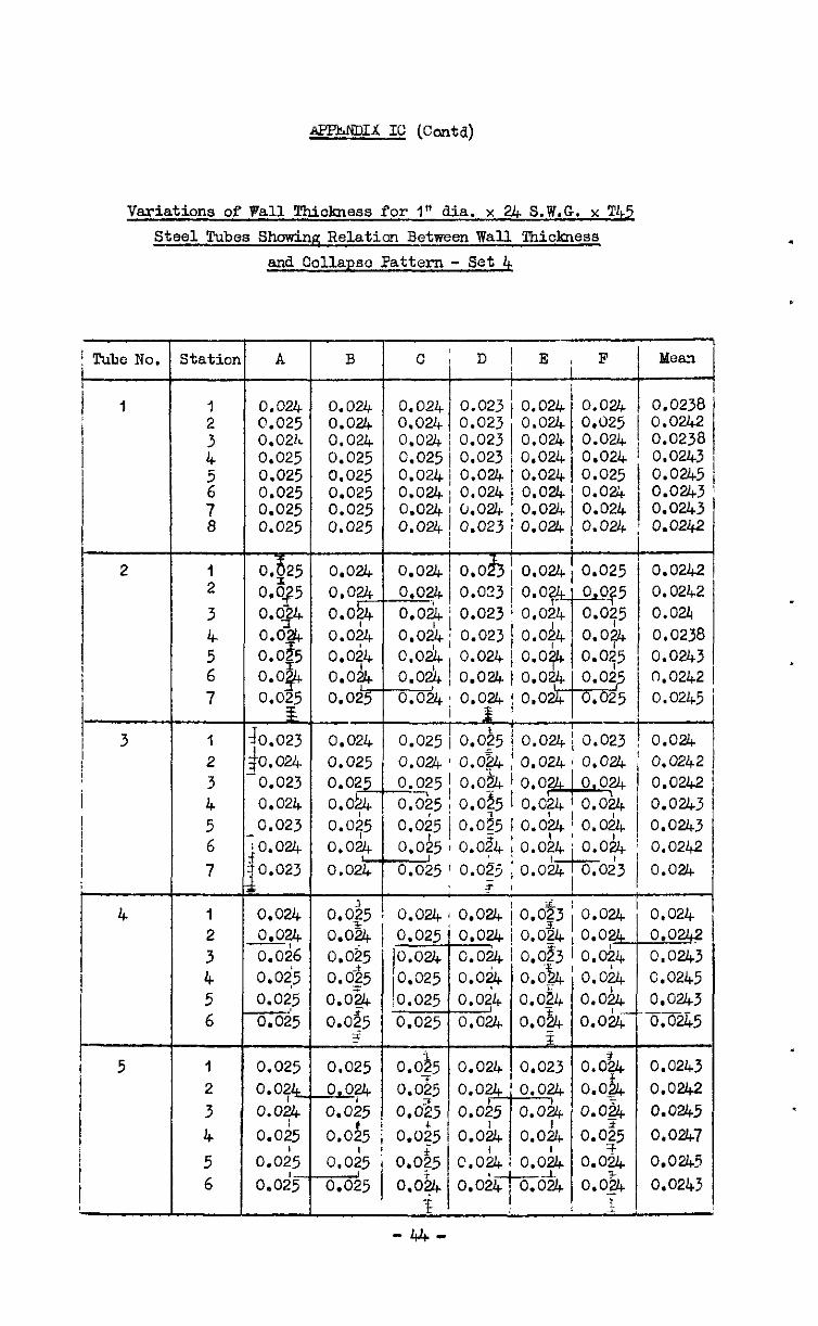
APJ?..mIx IC (Coda)
Variations of Pall !Chickness for I" dia. x 2& S.W.G. x Tk5
Steel Tubes Showing Relatia Between Wall lkiclmess
and Collapse Pattern - Set 4
Pubc No. ! I
l-
! I
i
Statior
1 2
3
4 5 6
7
qG 0.024 0.025 0.024 o.op o.o!G o.oz+ 0.035
0.0&k o.oi4
0.0 @+ o.oi4 0.025 0.025
1 0.023 2 0.024 3 0.023
4 0.024
5 G.023
6 0.024 7 0.023
1 0.024 2 0.024
3 o.oi6
4 0.015
5 6
0.025 0.025
A
0.024 0.024 0.025 0.024 0.021L 0.024 0.025 0.025 0.025 0.025 0.025 0.025 0.025 0.025 0.025 0.025
-- 0.024 0.025 0.02
?-- o.o+ 0.075
a.024 0.025r
0.025
0.0?4 0.0+ 0.025
0.045
O.O&
B l-
I
t
f
0.025
0.024 0.025
O.S5
0.0#5
t c& 0.023
0.023
0.023 0.024
0.024
0.024
f -4 0.0_25 o.oz%
o.oj4
0.09.5 0.0?5
o.og4 095 I !
0.025 1 0.025 i
0.024 1 0.024 I
c
0.024 0.024 0.024 0.025 0.024 0.024 0.024 0.024
0.024 0.024 -3 o.oyt 0.024 c.oA 0.02L o.ouc
D
t
0.023 0.023 0.023 0.023 0.024 0.024 0.024 0.023
0.025 0.0$5 0.024
Q&f4 0.025 0.024 0.025 0.0% 0.02%
0.035 j O.o$5 O.Ob4
0.0;5 ! 0.055 LO&t
O.025 o.o& o.oic i
E i
0.024 0.024 0.024 0.024 0.024 0.024 0.024 0.024 I c -,
F
0.024 0.025 0.024 0.024 0.025 0.024 0.024 0.024
-
0.024i 0.025
----+-- 0.02&\ 0.023
0.024' 0.024
o.o,u, ! 0-y
0.0:4 j 0.09
i
? 0.024 0.0242
0.0242
0.0243
0.0243 0.0242
o.of4 ; 0.024 0.024' O.Od4 I 0.07q-Ko~3 ; 0.024
MwB1
0.0238 0.0242 0.0238 0.0243 0.0245 0.0243 0.0243 0.0242
0.0242 0.0242
0.024 0.0238
0.0243 0.0242 0.0245
1
0,$3 i 0.024 0.024 0.024, 0.024 0.033 1 o.ob4
0.0242 0.02ij
o.& ’ 0.o.k 0.0245 0.024 o.oht 0.0243
-_--- o.o’$+ o.o& 0.0245
z
0.023 O.O’u, 0.0243
0.024 0.064 0.0262
o.h+ 0.0-5 0.0&5
o.oJl+ 0.0;5 0.0247
0.0;4 o.oL 0.0245
ti& O.O;& 0.0243
.
-44-
&FRiDIX IC (Contd)
.
Tube NO. Station A
6
O.oi4 0.024 0.024 0.024
7
5 0.024 0.024 O.O2l+ O.OF 0.024 0.024 0.024 7
.
- 45 -
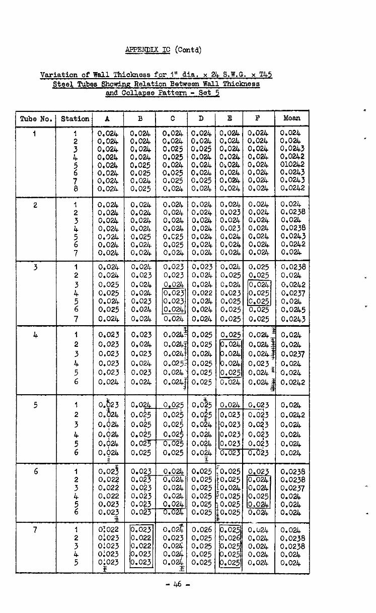
gmmx IC (coda) gmmx IC (coda)
Variation of Wall Thickness for I" dia. x UC S.W.G. x T4z Variation of Wall Thickness for I" dia. x 2% S.W.G. x T4z Steel Tubes Showing Relation Between Wall Thiclamss Steel Tubes Showing Relation Between Wall Thiclaress
and Collapse Pattern - Set 5 and Collapse Pattern - Set 5
Pube No. F 0.024
Moan
0.024 0.024 0.0243 0.0242 01024.2 0.0243 0.0243 0.02k-2
E
0.024 0.024 0.024 0.024 0;024 0.024 0.024 0.024
0.024 0.023 0.024 0.023 o.c24 0.024 0.024
0.024 0.025 0.024 0.023 0.025 0.025 0.025
0.025 ,024 ,024
e ,024
0.025 0.024
o.oue 0.023 0,023 0.023 0.023 0.023
0.025 0.025 0.024 0.025 0.025 0.025
C
0.024 0.024 0.025 0,025 0.024 0.025 0.025 0.024
0.024 0.024 0.024 0.024 0.025 0.025 0.024
0.023 0.023
0.024
o,o& 0.02li 0.0%: 0.025: 0.024 0.024;
D
0.024 0.024 0.025 0.024 0.024 0.024 0.025 0.024
0.024 0.024 0.024 0.024 0.024 0.024 0.024
G-i-j 0.o.a 0.024 0.022 0.024 0.024 0.024
0.025 0.025 0.024 0.025 0.025 0.025
0.024 0.024 3.024 3.024 0.024 0.024 3.024 0.02L
3.024 0.024 0,024 3,024 3.025 0.025 0.024 0.025
0.024 0.024 0.024 0.024 0.024 0.024 0.024
0.024 0.024 0.024 0.024 0.024 0.024 0.024
0.024 0.0238 0.024 0.0238 0.0243 0.0242 0.024
0.0238 0.024 0.0242 0.0237 0.024 o.ouc5 0.0243
0.024 0.024 0.024 0.024 0.924 0.024 o.ouc
0.024 0.024 0.025 0.025 0.024 0.025 0.024
0.024 0.024 0.024 0.024 0.025 0.024 0.024
0.024 0.023 0.024 0.024 0.023 0.024 0.024
0.023 0.024 0.023 0.024 0.023 0.024
0.025 0.025
0.025 0.025
0.023 0.023 0.023 0.023 0.023 0.024
0.024. 0.024: 0.024. 0.023 0.024 0.024 :
0.024 0.024 0.0237 0.024 0.024 0.0242
0.024 0.0242 0.024 0.024 0.024 0.024
0.623 0.524 Oh+
Oh+ 0.+4
0.g24
I 0.023 0.02? 0.02? 0.022 0.023 0.023 2
Of022
0.024 0.0?5 0.0?5 0.025 o.o$Y 0.025
0.022 0.0?3 0.0?3 0.023 0.023 0.023
iz+z 0.022 0.022 0.023 0.023
Lb&25 0.02j 0.025
0.0-!?5 o.os5 0.024 o.oi.4 o.oi4 0.oh.h
0.023 q3 o.oq3 0.0?3 0.023 0.023
JJ.3 0.024 0.024 0.024 0.024 7cTm
0.027 0.023 o.ou; o.oq 0.024
I
0.025 0.025 0.025 0.025 0.025 0.025
0.026 0.025 0.025 0.025 0.025
0.02 0.024
El 0.024 0.025 0.024 0.024
0.0238 0.0238 0.0237 0.024 0.024 0.024
-~- O.U24 0.024 0.024 0.024 0.024
0.024 0.0238 0.0238 0.024 0.024
01023 0:023 0!023
-46-
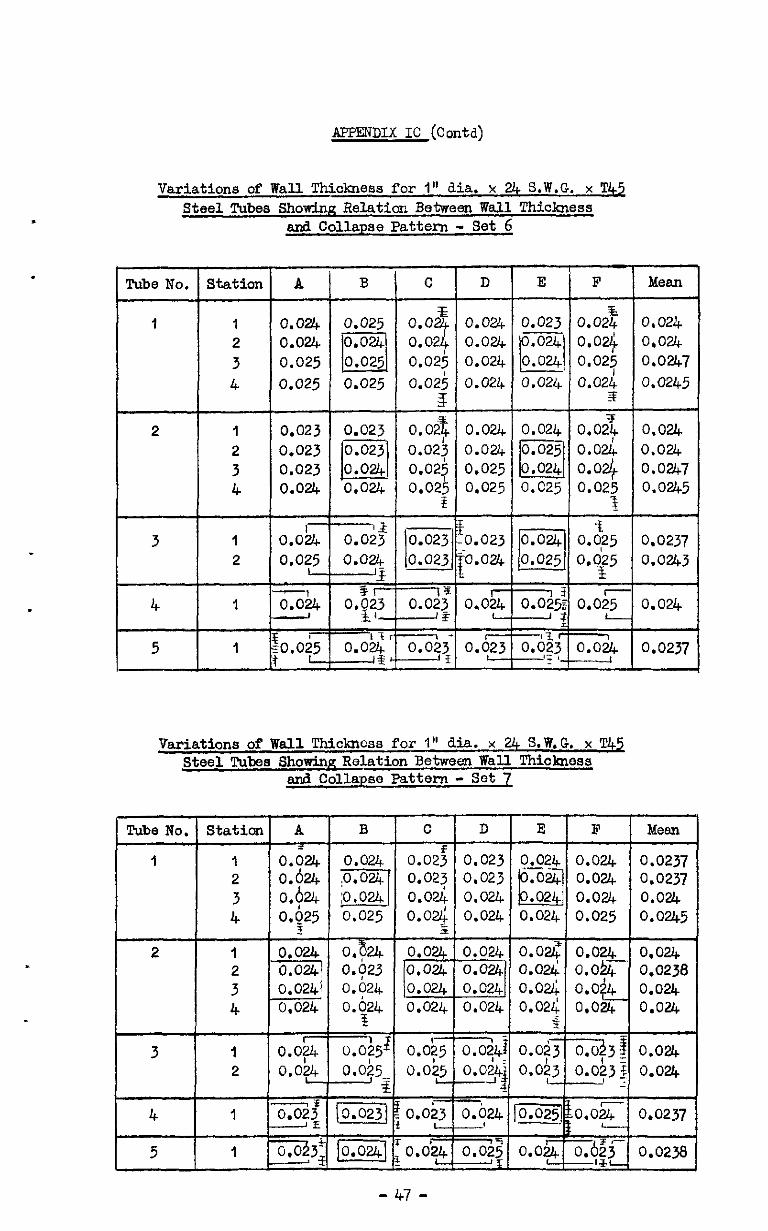
APPENDIX IC (Coda)
Variations of Wall Thickness for 1" dia. x 24 S.W.G. x T45 Steel Tubes Showing Relatior: Between Wall Thickness
ard Collapse Pattern - Set 6
.
, Tube No. Station A B C D E F Mean
I 1 0.024 0.025 o.Oif 0.024 0.023 O.o2z 0.024 2 0.024 0.021: 0.024 0,024 3 0.025 0.025 0.024
PI ,024 o.od 0.024 0.025 0.0247
4 0.025 0.025 0.02; 0.024 3
0.024 0.022 0.0245
2 1 0.023 0.023 O.O?t 0.024 0.024 2 0.023 0.0213
0.024 0.02x 0.024 0.024
3 0.023 0.02j 0.025 El 0.025 o.od 0.024 0.02$ 0.0247
4 0.024 0.024 0.02; 0.025 O.C25 0.02; 0.0245
3 1 o.ob4
2 0.025
4 1 x&t -
I I-‘ 1 5 1 so.oi5 3, 0.023 Oi$, 0.024 0.0237
1 7 ITS ~~2 ,
Variations of Wall Thickness for 1" dia. x '24 S.W.G. x T42 Steel Tubea Showing Relation Between Wall Thickness
and Collapse Pattern - Set 7

APPEXiDIX IC (Contcl)
Variations of Wsll Thickness for 1" dia. x 24 S.W.G. x T45 Steel Tubas Showinn E'?lation Between Wall Thickness
and Collapse Pattern - Set 8
1 I
4 I 1
f f , 5 I : 0.024
,I 0.024
f c
6 zo.d23 1:
1 0.023 : I
J ‘C
7 1
f 0.025 0.02' 0.02 0.026 0.02 0.02 i
I I o.d25 0.0.2
-I- T
.t-
4 0.023 0.oh.G
' i 3 x- 0.026 0.0’;;; -
0.0237
i
3.024
0.024
0.0238 1
1 0.0235
-4B-
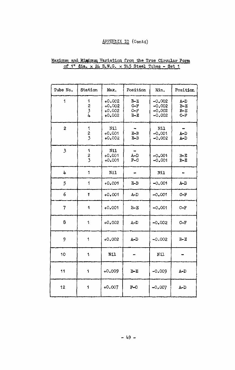
@?JWIX IC (Contd)
Maximum and Mbimun Variation from the True Circular Form of 1" dia. x 24 8.W.G. x T45 Steel Tubes - Set 1
Kin. Position
-0.002 A-D -0.002 E-E -0.002 B-E -0.002 C-F
Nil - -0.001 A-D -0.002 A-D
-0.cQl BE -0.001 E-E
Nil -
44 -0. OiJl A-D
-0.001 C-F
- 49 -
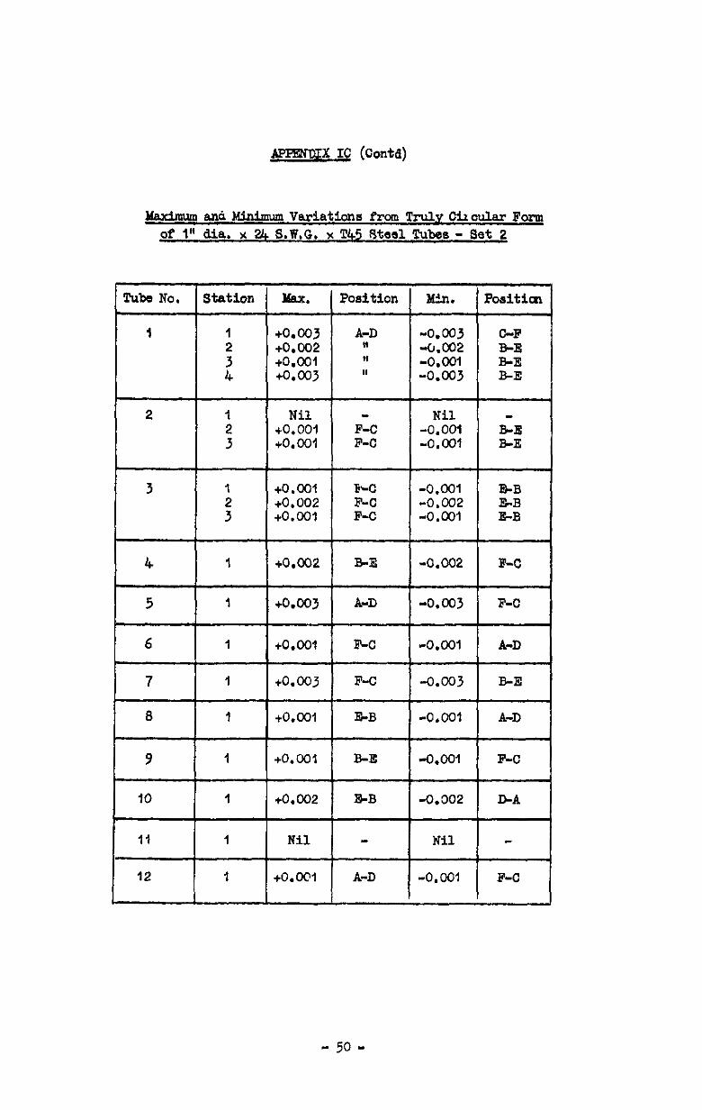
APPEXDIX IC (Contd)
MaxburnankhfinimnVariatlona Prom Tru.lpChoula.rFcxm ofIndia x2& * S.W.G. x T45 s=%eel Tubes - Set 2
Tube No. Station
I I 2
2 1 2 3 I--+- 3 1
:
2 1 2 3
3 1
:
4 I
5 1
4 I I-+ 5 1
l-L-L- 8 I k 9 1
7 1
8 I
9 1
IO 1
11 I
12 1
Max. Position Min. Poaitial
+0.003 A-D -0.003 C-F +o.C02 " 4J.002 +O.ool " -0.001 z +0.003 In -0.003 B-E
Nil - Nil - +O.OOl -0.001 BE +O.OOl ;I: -0,cxJl B-B
+O.ool PM2 -0.CQl B-B +0.002 -0.002 l&B +O.ool -0.001 E-B
+O.OC'l 1 A-D I-O.001 ( F-C 1
- 50 -
APPENDIX IO (conta)
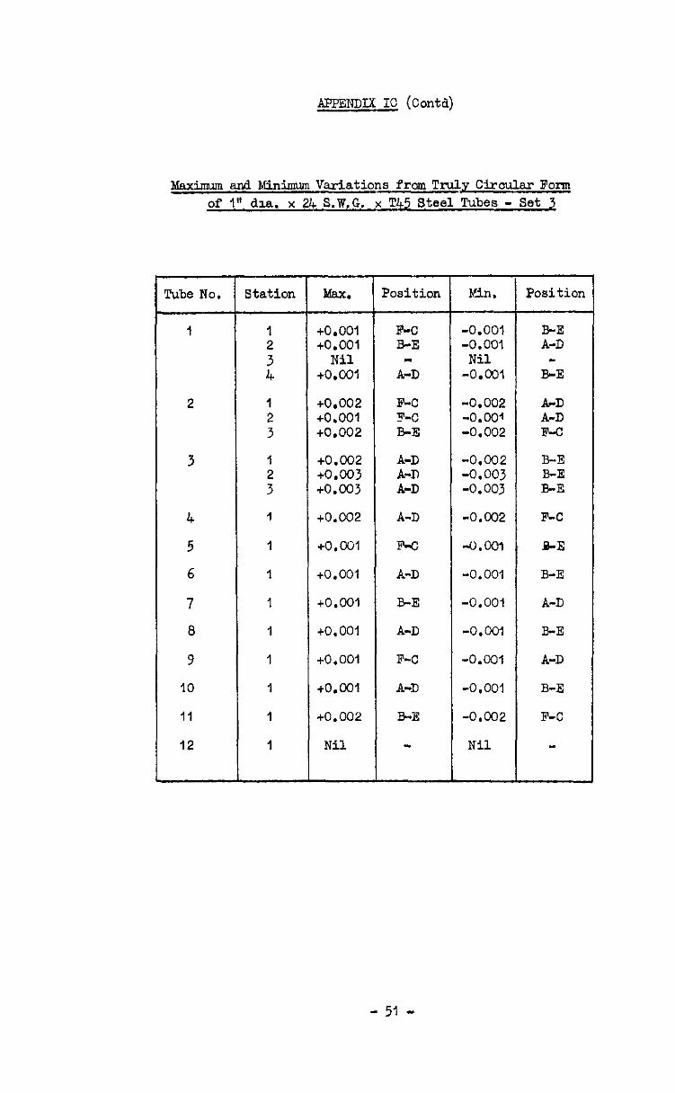
bfaximm and Minimum Variations fmm Truly Circular Form of 1" dza. x 2l+ S.W.G. x TM Steel Tubes - Set 3
Tube No.
1
2
3
4
5
6
7
8
9
IO
Ii
12
Station
1
1
Max.
to.oo1 to.001
Nil +O.col
co.002 to.001 to.002
+0.002 to.003 to.003
to.002
+o.a31
to.001
to.oo1
+o. 001
tO.00~
+O.ool
to. 002
Nil
Position Kin.
F-C -0.001 B-E -0.001
Nil A-D -0.001
F-C -0.002 F-C -0.001 B-E -0.002
A-D -0.002 A-D -0.003 A-D -0.003
A-D -0.002
F-c -0.m
A-D -0.001
E-E -0.001
A-D -0.001
F-C -0.001
A-D -0,001
B-E -0.002
Nil
Position
B-E A-D -
B-E
ArD A-D F-o
B-E B-E B-E
F-C
&E
B-E
A-D
B-E
A-D
B-E
F-C
- 51 -
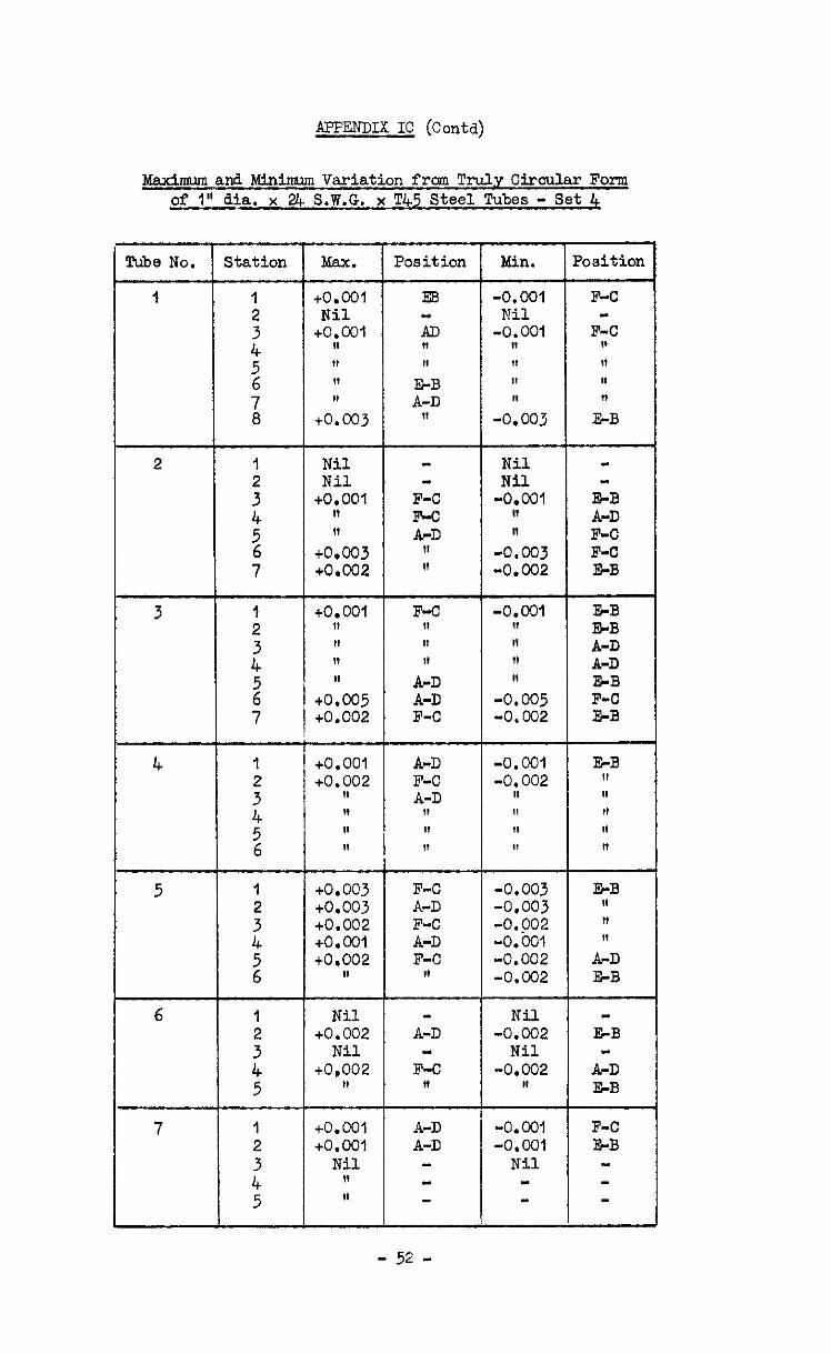
APPENDIX IC (Contd)
Mexinnun and Minim Variation from Truly Circular Form of 1" dia. x 24 S.W.G. x T45 Steel Tubes - Set 4
Min. ?osition Pube No. Station Max. Position
1 -0. COI Nil
-0.001 II I, !I 1,
-0.003
Nil Nil
-0.001 II n
-0.003 -0.002
-0.c91 I, II 11 I,
-0.005 -0.002
-0.001 -0,002
II 4, 11 It
1
: 4 5
76
1 2
z
2 7
to.001 Nil
+O.col II 11 11 I,
+0.003
Nil Nil
+O.OOl II I,
+o.c03 +0.002
to.001 11 I, II II
to.005 to.002
+O.OOl to.002
!I H II II
E3
F-C F-C A-D
,I II
F-C 1, I, If
A-D A-D F-C
2
SB
E:: A-D E-B F-C FrB
3
4 A-D F-C A-D
11 II 11
5 to.003 F-C to.003 A-D +0.002 F-C +O.col A-D to.002 F-C
8, II
-0.003 -0.003 -0.902 -0.oQ1 -0.002 -0.002
Nil -0.002
Nil -0.002
I,
Nil to.002
Nil to.002
II
A-D
F-C 1,
+O.OOl to.oa
Nil 1, II
A-D A-D
-0.001 -0.001
Nil
F-C l&B
- 52 -

APP?ZiDIX IC (C&d)
Maxumm and Minimum Variatisn from Truly Circular Folm of I" dia. x 2J+ S.W.G. x T45 Steel Tubes - Set 5
Tube No. Station IdaL Position Min. Positi
A-D 8, 11
A-D B-E
?iil Nil
to.001 tt II
Nil to.001 to.oo1
F-C BE F-C
F-C II
Nil Nil
4.001 -0.001 -0,001 Nil
-0.001 -0.001
Nil to.co1 to.002
II " II
tO.001
A-D " "
E-B 11
A-D
F-C E-E
11 F-C
" B-E
Nil -0.001 -0.002 "
1, 11
-0.001
A-D -0.002 F-C 11 II BE II 11 F-C ,I -0.004 F-C II -0.002 F-C II -0.004 F-C II -0.001 8,
3 to.002 11 I,
to.004 +o.c02 to.004 to.001
+o.ocJ1 to.002 11 to.003 II +o.ooi
4 B-E -0,001 A-D -0.002 F-C -0.002 B-E -0.003 II II n -0.001
F-C BE B-E SC F-C A-D
-0.001 -0,ciM Nil
11 I,
-0.002
A-D II
A-D
+O.OOl ”
Nil I, I,
to.002
F-C II
F-o
to.001 A-D -0.009 F-C CO.001 II .o. 001 " to.002 " BO.002 11 co.co2 G-B -0.002 A-D CO.001 F-C -0.001 A-D to.002 11 *o,ccJ2 I&B
7 to.001 to.002
to:oo, n
A-D F-C Z-B
II "
~O.oQl .0.002 -0.002 .O.OQl ~0.001
l&B ,I
F-C A-D
I,
- 53 -
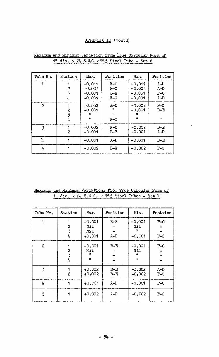
APPE??DIX IC (Contd)
Maxumun and Minimum Varlatlon frcm Tee C~rcu1e.r Form of 1" dia. x 24 &KG. x T45 Steel Tube - Set 6
Tube No. Station Max. Position Kin. Position
1 1 +O.Oll 2 +o. 003 3 +o. 001 1, +O.OOl
F-C -0.011 A-D F-C -0.00: A-D B-E -0.OCl F-C F-C -0.001 A-D
2 1 +0.002 A-D -0.002 F-c +O.OOl " -0.001 B-E
1, II 0 F-C II II
3 1 +0.002 F-C -0,002 EE 2 to.oo1 B-E -0.001 A-D
-4 1 to.oo1 A-D -0.001 B-x
5 1 to.002 B-E -0.002 F-C 1
Maxzmum and Minimum Variations from True Circular Form of I" dia. x 24 S.W.G. x 7245 Steel Tubes - Set z
Tube No. 1 Station 1 Msx. 1 Position 1 Min. 1 Position 1
2 1 to.oo1 2 Nil
B-E
A-D
B-E
5 I 1 1 to.002 1 A-D I-O.002 1 F-C 1
- 54 -
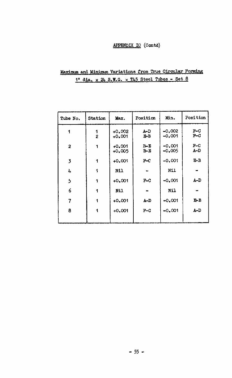
lPPENDIx IC (conta)
3
1” dia. x 2f+ S.W.G. x TJ+5 Steel Tubes - Set 8
cube No. I Station
I I 2
2 1
3 1
4 I
5 I
6 1
7 I
8 I
Max.
+0.002 +O.ool
+O.ool +0.005
+O.ool
Nil
+O.ool
Nil
+0.w1
+O.ool
Positicm Min.
A-D -0.002 5h-B -O.Wl
B-E -0.001 B-S -0.005
F-C -0.001
Nil
l5.C -O.Wl
- Nil
A-D -O.ocl
F-O -0.001
-
Position
F-C F-C
F-c A-D
E-B
A-D
l%B
A-D
- 55 -
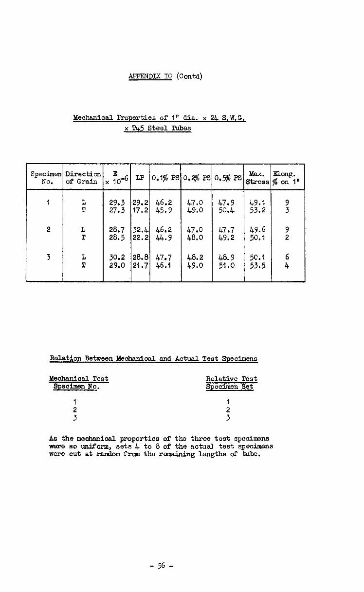
APPENDIX IC (Contd)
Mechkniaal Properties of I" dia. x 24 S.W.G.
x T45 Steel Tubes
29.3 29.2 46.2 47.0 47.9 c9.1 9 27.3 17.2 45.9 49.0 50.4 53.2 3
28.7 32.4 46.2 47.0 47.7 49.6 9 20.5 22.2 44.9 48.0 49.2 50.1 2
30.2 20.0 47.7 48.2 48.9 5C.l 6 29.0 21.7 46.1 49.0 51.0 53.5 4
Relation Between bfechsnical and Actual Test Specimens
1 1
: 2 3
As the mechanical proporties of the three test specimms were so uniform, sets 4 to 8 of the actuall test specimens were cut at random frcm the remaining lengths of tube.
- 56 -
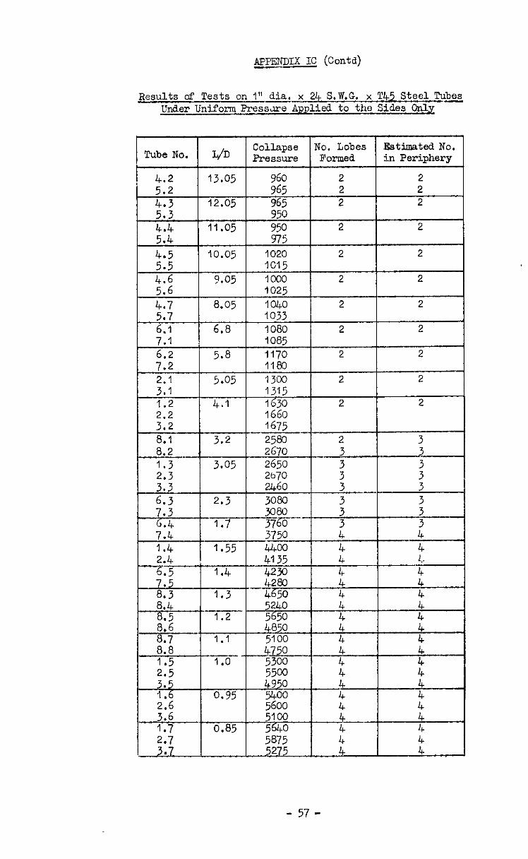
APPENDIX IC @odd) CI-
Results of Tests on I" dia.-x !3+ S.W.G, x l’45 Steel Tubes Under Uniform Pressure Applied to the Sides only -
Estimated No.
3.6 5100 1.7 0.85 :8750 sl, t ::
2.7 . 5275 :: ::
- 57 -
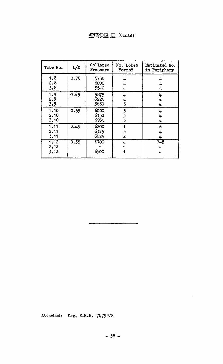
&PENDIX IC (Cord) .- -- --
Tube No. L/D ColAapse No. Lobes E%timated No. Pressure BOXTh?d in Periphery
1.8 0.75 4 2.8 z&z : 3.8 5540 4 :
;:; 0 0.65 $2 5875 i: 3 4 i
1.10 0.55
2.10 2: : 3.10 5965 3 i
1.11 0.45 6200 1 6
2.11 3 3.11 2 :: , 1.12 0.35 6700 4 7-8 2.12 3.12 69;;o 1
MxLohed.: B-g. S.M.E. 74799/R
- 58 -

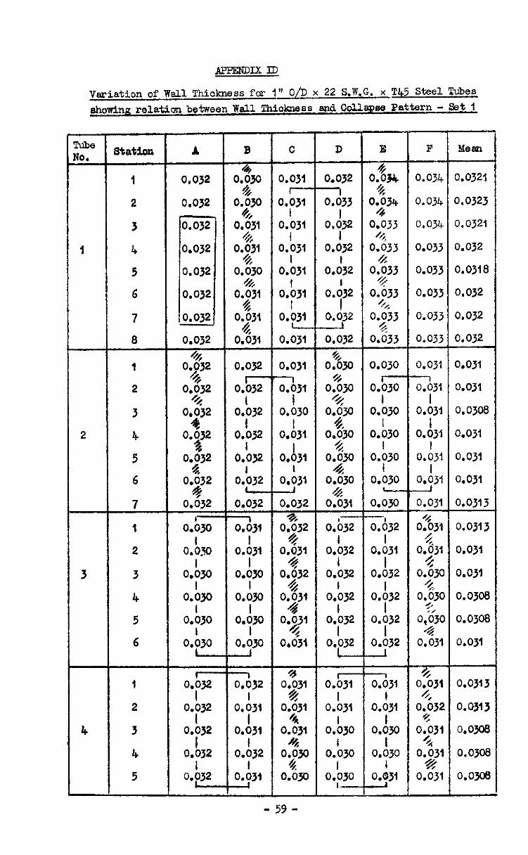
Variation of Wsll Thiokmss for I" O/D x 22 S.W.G. x 'I!45 Steel Tubes showing relation between Wall Tkioknsss and Oolla~pse Pattern - Set 1
Cube $0.
I
2
3tation
1
2
3
4
5
6
7
1
2
3
4
5
6
A 0.032
0.032
0.032 +G
0.032 %
0.232
0,$2
0.$32
0.3
0.92
0.632 I-
0.030
O.&O
O.bJO
o.b3*
O.&Q
O.b30
Oh2 I
0.032 I
0.032 I
0.032 I
B
T 0.030
& 0*;30
0.$31 h
0.;31
O.&O 4
0.;31
Oj3l
0.631
0.032
O&F
Oh32
0.L I
0.032
oh32 L
0.032 =i- 0.031
I 0.031
I 0.030
O.&O
O.&Q I
0.030
7 0.032
0.;31 I
0.031
oh32 I
0.031
C
3.031
3.$- D.031
I 0.031
I 0.031
o.b31
o.L3,
0.031
0.031
a31 I
0.030
o.i31
0.b31 I
0.031
0.032 %%
0.032 %
oi31
0232
0.:3, 4
y531
0,431
0$31 $
0.031 /*
0.031
D
0.032 1 0.033
I
o*932 0.032
o.d32
OX!32 I
CL032
0.032
OgO %
0.030 *
O*YO o.$o
0.9
0.:30 4
0.031
O.&Y-
O.b,2 1
0.032
Oh32 I
0.032
0.032 L
0.6
0.b31
0.b30
0.'030 I
0.030 I-
E
0$34 0$34
0.033 +,
0.033
0.$33
o;j33
0.93
o.G33
0.030
O.&t- I
0.030
oh30
0.;30
0.030 -
0.03Q
-1 0.032
I 0.031
I 0.032
oh32 I
0.032 I
0.032
331 I
0.031
O.&O I
0,030 i
331
F
0.034
0.034
0.034
0.033
0.033
0.033
0.033
0.033
0.031 -l 0.031
I 0.031
I 0.031
I 0.031
I 0.031
0.031
0%3l g
o*z3’ O.&C
9, 0.030
5, o,bic
4 0.031
% 0.031
4 0.032
* 0$31
0.;;31 *
0.031
xeau
0.0321
0.0323
0.0321
0.032
0.0318
0.032
0.032
0.032
0.031
0.03i
0.0308
0.031
0.031
0.031
0.0313
0.0313
0.031
0.031
0.0308
0.0308
0.031
0.0313
O.Q313
O.Qjos
0.0308
o.om
- 59 -
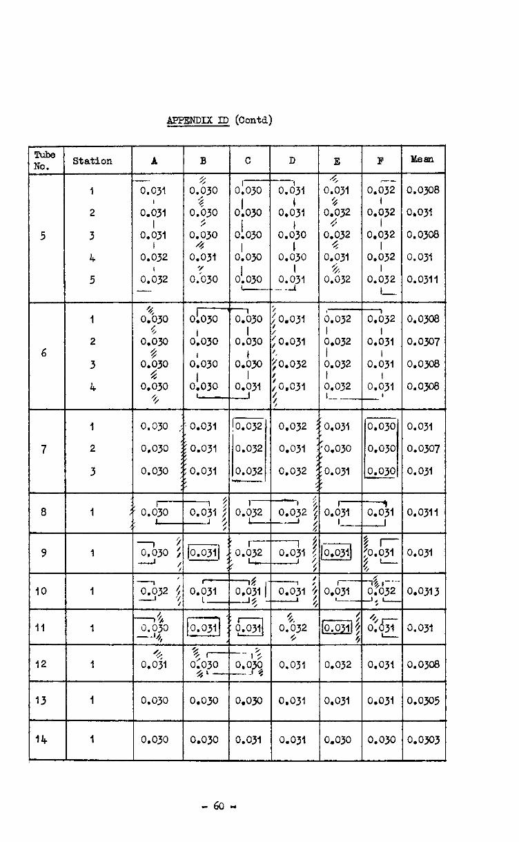
A,PmNDIx ID (conta)
cube JO.
5
6
F
o.ocj2 I
O*s)j2 0.032
I 0.032
o.i132 I-
CA312
o.A31 I
0.031
o.d3i -'
Mean
0.0308
0.031
0.0303
0.031
0.0311
0.0308
0.0307
o.om
0.0308
0.031
0.0307
0.031
0.0311
0.031
0.0313
0.031
0.0308
0.0305
0.0303
A
0,031
0.031
o.h31 I
0.032
o.d32 -
0330 %
0.030 $
O*Z30 0.630
%
0.030
0.030
0.030
C
01030 I
0.030 I
0.030
01030
0'030 :
a30
o.b,o
0.b30 I
y31
0.032
0.032
0.032 -5
D
--I 0.031
0.d31
o.d30 I
0.030 I
0.;31 . .
0.031
0.031
0.032
0.031
0.032
0.031
0.032
Station
I
2
3
4
5
1
2
3
4
1
2
3
1
I
1
I
1
1
1
B
2 0.030
% 0.030
5 0.030
4 0.031
OS30
01 .
01030
olo30 I
0.030 -
0.031
0.031
0.031
E
4 0.031
% of32
0.;32
0.031 5
0.032
6.032 I 0.032
0.032 I 0.032 I.- _-_
0.031
:0.030
0.031
0.030
0.030
0.030
r_
7
8 T--
0.030 -
0.g 0.0% I --.
1 0.031 J
-, :
0.032 : -2 ;
----I; 0.031 ! --I
$1 !
%, 0.032
//
0.031
0,031
-7 :
0.031 ; -1 :
/o.ojil 9 r-
0.032 o.oji)
o.oT I---_
@jj:
ilo% . :L I -I$,-.- 0.032 J. L ,
/J/ 7 0.031
0.032 0.031
--I ‘, 0.030 : - i
7 ' 232 $
+ l/s 0.030 - -44,
,.$I
0.030
IO -
0.031 I-
I 0.031
% r-- o;qjo
4-
0.030
II
12
0.031 13 0.031
14 0.030 0.030 0.031 0.031 0.030 0.030
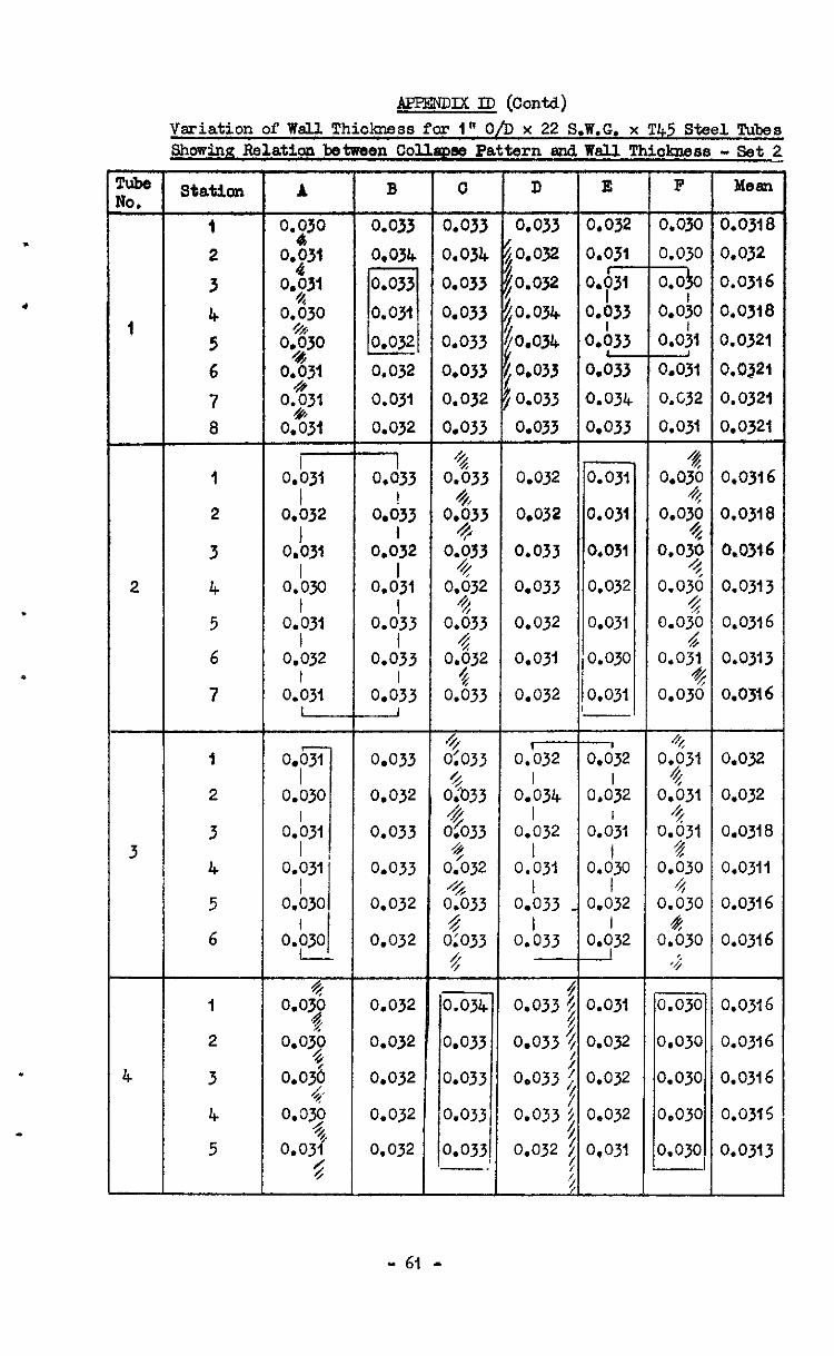
,
l
.
i
.
”
cube VO.
I
4
APEENDIX ID (Contd) Variation of Well Thickness for I" O/D x 22 S.W.G. x T45 Steel T&es Showinn Relation between Collwm Pattern ami W&l Thiakness - Set 2
Station
1
2
3
4
5
6
7
8
1
2
3
4
5
6
I
2
3
4
5
A
0.:30
y31
0931
O$J
og30
0231
0$3l
0.631
O.&l I
0.032
0.1031
Oh0
0.\31
0.032 I
0.031 -
0.030
4 0.03$
0.09
o.ojE, 4;
0.y
0.03f
$
0.032
0.031
0.032
1 0,033
ok33 1
0.032 I
0.031
o.d33 I
0.033
0.0:3 --I
0.033
0.032
0.033
0.033
0.032
0,032
0.032
0.032
0.032
0.032
0.032
0
GE 0.034
0.033
0.033
0.033
0.033
0.032
0.033
% 0.633
%/
4 0.;32
0.633
F 0:033
$033
0%33 3
0.032 6 0.033 +
0:033 <
o.ojq 0.033
0.033
0.033
0.033 -.
D E
0.033 0.032
/o.w 0.031
ro.032 0.05
io.034 oh33
:o.oy+ Oh33
,0.033 0.0%
0.033 0.034
0.033 0.033
0.032 0.031
0.032 0.031
0.033
0.033
0.032
! 0.031
0.032
0.031
0.031 0.030
0.032 0,031
1 0.032 0.632
Oh34 cd32 I
0.032 o.d31 I
0.031 o.d30 I I
0.033 _ 0.032
oh33 I
0,032
4 0.033 4
%
0.031
0.033 $ 0.032 /
0.033 2 7
0.032
0.033 5 #
0.032
0.032 t 0.031
$
F
o.030
0.030
-zio
o.ofo
O.Ofl - 0.031
O.C32
0.031
% O*OT 0.09 0.05
0.02
0.03% 4
0.031 %
0.030
4, Of31
o.fJ31 %
oh31 5
0.030 4
0.030 2%
0.030 *J
0.030
0.030 I 0.030
0.030
0.030
MeaPl
o.ojle 0.032 0.0316
0.0318
0.0321
0.0321
0.0321
0.0321
0,0316
0.0318
0.0316
0.0313
0.0316
0.0313
0.0316
0.032
0.032
0.0318
0.0311
0.0316
0.0316
0.0316
0.0316
0.0316
0.0315
0.0313
- 61 -
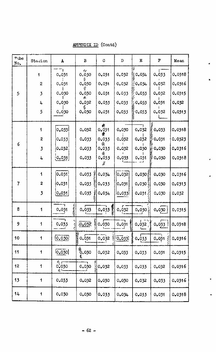
APF?mvx ID (conta)
robe ‘TO. Sthcion A B C n E F Mean
-- # - I 0.031 a%30 0.031 0.032 $0.034
4 oh33 0.0318
$ 2 o.;,, 0.030 0.031 0.032 $0.034 0.032 0.0316
I $ 5 3 0.030 0.030 0.031 0.033
I 4, Y ;0.033
I 0.032 0.0315
4 0.030 0.032 0.033 0.033 jo.033 o.b3i 0.032 I 4
5 0.030 0.030 0.031 0.033 B IO.033 a.;32 0.0313 I 4 I
- 62 -

APPENDIX ID (conta)
Variations in Wall Thickness fbr 1 0 Dia. x 22 S.W.G. x T45 Steel Tube wowing Relation between Wall Thiclmess snd Collapse Pbttern - Set 3
lube lo.
1
2
itation
1
2
3
4
5
6
7
8
I
2
3
4
5
6
7
A
~$32
$32
0.632 4
0.632 r%
0.032
f&32 6
O*jJ2 oh32
%
0.031 -
0.030
0.b30
o&31
0.631
0*!3l-
0.032
0.032
0.032
0.032
0.032
0.032
0.032
G 0.032
4 0.032
0,!32 4
0.032 $
0.032 4
B
0.031 -
o.b31
o.b31 I
0.031 I
0.032
O.b,l
oh31
O.&S-
O.03f --l 0.031
o.ofi o.ofi o.o:, o.o:, 0.031
0.032
0.032
0.032
0.032
0.032
0.032
0.02 I
0.032
oh32
o,b32 I
0.032
c
1.030
;Il31
3.d31
3.d3l I
3.03t
o.d31
o.d3,
&31
% 0.032
0 0.032
h 0.032
0.832 44
0.032 4
0.032 4
0.032
0.031
0.032
0.031
0.031
0.031
0.032 --
1 0.031
o,b3i
0.b32 I
0.032 I
0.032 -1
D
3.:30 4
0.031 4
y31
O.&O 4
WJJO $
0.;30
0.~30 %,
0.031
0.032 - 0.632
oh32
0.632
oh32 I 0.032
9.032
0.w 0.030
0.031
0.030 0.031
O.03l
4 0.030 % 0.031
e O*OY 0.03:
$ 0.031
1 E d 0.031 I- 0.031
o.h31
0.b30 ! 0.030
0.b30
o.lo3, I. 0.031
0.032
a 0. 31
o.d31
o.d3,
0.d31 I 0.031
0.031
0.031
0.030
0.031
0.031
0.031
0.031
I 0.030
0.b30 I 0.030
o.b31
o.b31 -
F
0.032 -i 0.032
0.0:2
o.o:t I
0.031
o.ofi
0.0;2 -I 0.032
0.:30 4
0.030 4
0.p
0.y
0.631 f?
0.031 4
0.031
--1 0.031
o.d31
0.0~1
0.0~1
o.o:, -
Mean
0.031
o.o3r3
0.0313
0.0308
0.031
0.0308
0.0311
0.0315
0.0313
0.031
0.031
0.0311
0.0313
0.0313
0.0315
0.0311
0.0311
0.0313
0.0313
0.0318
0.0315
0.0311
0.0311
0.0313
0.0315
0.0315
- 63 -
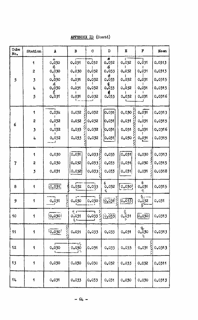
A.ePmmx ID (cord)
Liz (0. -
5
C D E F IdeEm
0.0313
0.0313
0.0315
0.0315
0.0316
0.0313
0.0315
0.0316
0.0315
0.0313
0.0315
0.0318
0.0315
0.031
0.0313
0.0313
0.0313
0.0311
0.03~3
A
- 0.03;:
0.b32 I
0.032 I
0.032 --A
0.030
0.09
0.03i
- (o.oji;
1
0.031 -I
/o.ojOi --
10.03Of .-
- 0.030
L
0.m
0.031
station
1
2
3
4
5
I
2
3
4
I
2
3
I
I
I
I
I
I
1
B
O.bji
O.&a
0.631 I
0.031
o.b31 I.-
;;;1032
oh32
0.932
0.032
O.b32
0.032 0.032
0.032 0.032
0.033 0.032
0.033 0.032
oz32 4
0.033 4
0.033 4
0.033 d
0.033
-l 0.031
o.h31 I
0.031
o.d3, I
0.031
-
oh32
O.b,
0.&2
oh32 I
0.032 L
0,030 j
0.031 I
0.031
0.030
0.0301 - --_I
0.031
0.031 1 0.031
0.031
0.033
0,033
0.033
0.0% 0.031
o.b31 I
0.031
0.030 j 4
0.030 !
0.031 : :
0.033: /
0.033;
0.033;
6
7
o.oz 0.043 --I
& 0.032 '4,
-- (o.ojf
8
9 I--
0.030 1-
--Ii 0.030; -b :
IO t, -
0.031 $-
- --- ;o.ojjl
5
0$31 //
0330 +,
5 :
0.031 ; /
0.032
II 0.03
1% 0.030 -J ‘i
0,033
0.033
0.031
0.033
0.033
0.033
0.031 12
13 0.030 0.030 0.032
14 0,033 0.033 0.031 0.030 0.030
- 64 .
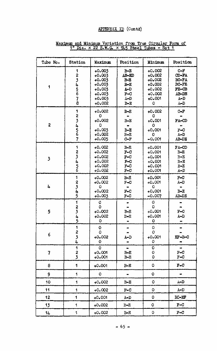
AF'PJ!NDIX ID @orhI)
Maximum and Minimum Variation from True Circular Form of 1" Dia. X 22 S.W.G. X T45 Steel Tubas - Set 1
Maximull Tube No. Poeiticm
GF CD-FA BGFA BGFE FE-CB AR-DE
A-D A-D
GF
FA-CD
F-C
A&
FA-CD B-E B-E B-E B-E A-D F-o A-D
B-E AB-DE
F-C A-D
-
m-B-C
F-C F-C
F-C
m
A-D
A-D BC-EF
F-C
F-C
Position Minimm
+0.002 to.002 IQ.002 +0.002 +0.002 +0.002 +O.Wl
0
+0.002 0
+O.ool 0
+0*001 0
-0.00-l
+0.003 to.003 +o. 003 +0*003 to.wj +0.003 to.003 to.002
+o.c02 0
to.002 0
+0.003 to.002 +o. 005
ED B-E B-E A-D F-C A-D B-E
B-E
B-E
B-E B-E C-F
1
to. 002 to.002 +0.002 to.002 to*002 to.002
to.002 to.002
to. 001 +o. 001 to.001 +o. OM +o. 001 +o*ool
to.ool to.ool
0 to.oo1 -0.007
0 0
tO.Wl +0.00-l
0
B-E F-C F-C
E F-C BE F-C
m F-C F-C
B-E B-E
m
0 to.002 +o.c03
0 0
+0.002 +0.002
0
0 0
+0.002 0
A-D
0 0
tO.Wl 0
: 3
0 to.w1 to.001
E-E B-E
0 0 0
8 1 +o .OOl B-E 0
0
0
0
9
IO
II
12
13
lib
0
to.002 B-E
F-C A-D
B-E
to.002 0 +o.ool
1 +0.002 0
1 to,002 B-E n
- 65 -
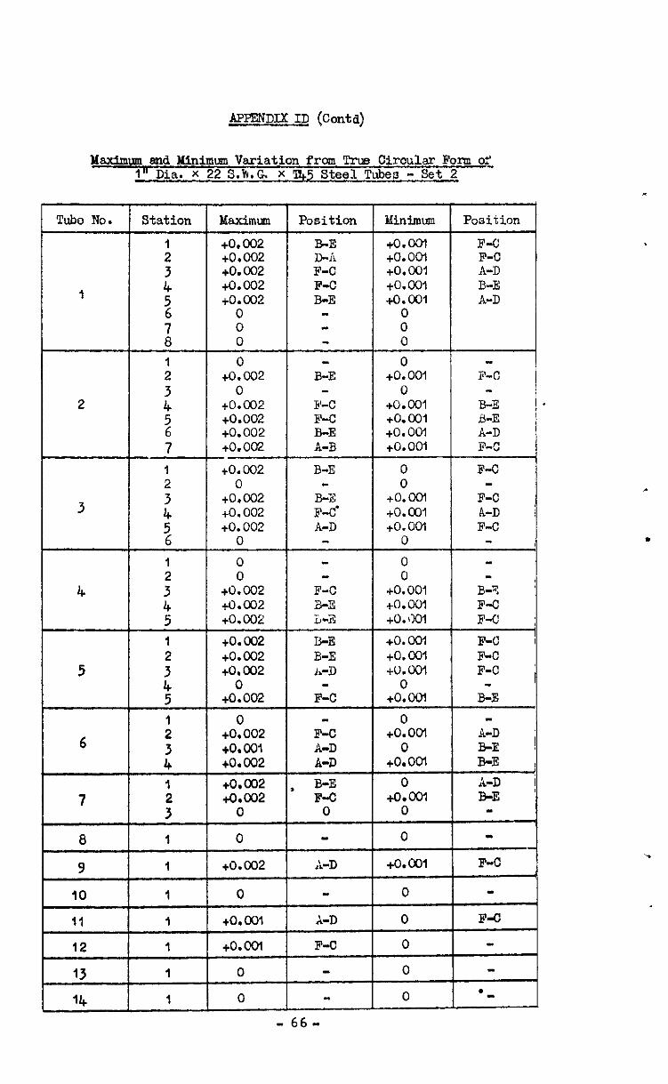
APPENDIX ID (C&d)
Yax&nnu and Minimum Variation from !iYlls Circular Form of- I" Dia. X 22 S.k.G X Q5 Steel Tubes - Set 2
'Pa&e No. Station ?&&mm adinimum Position
R-E D-ii F-C F-C B-E
-
B-E
F-C F-C B-E A-B
B-E -
B-3 F-d A-D
F-C a-3 L-2,
B-E B-E I.-D
F-C
F-C A-D A-D B-E F-C
0
A-D
A-D
F-C
-
Position
F-C F-C A-D B-E A-D
F-C
B-E B-E A-D F-C
F-C
F-C L-D F-C
B-T F-C F-C
F-C F-c F-C
B-E
A-D B-E B-E A-D B-E
F-C
F-C
l -
to.ool to.ocl tO.001 to.001 tO.001
0 0 0
0 to.co1
0 to.001 +o. co1 +o. 001 +o. 001
0 0
+o.ool to. COI +o. 00-l
0
0 0
to. 001 to.oo1 to. Go1
+o. COI to. 001 to.co1
0 +o.ool
+0.002 +0.002 +0.002 +0.002 +o.a32
0 0 0
0 +o.c02
0 to.01): +0.002 to.002 +0.002
+0.002 0
+0.002 +0.002 +0.002
0
0 0
to.002 +0.002 +o. 002
to.002 +o.c02 +0.002
+0:002
0 +0.002 +o. 001 +0.002
+0*002 +o.c02
0
0
.
3
.
6
0 +0.00-l
0 to.ool
0 tO.0O-l
0
0 8
+O.ool
0
0
0
0
0
- 66-
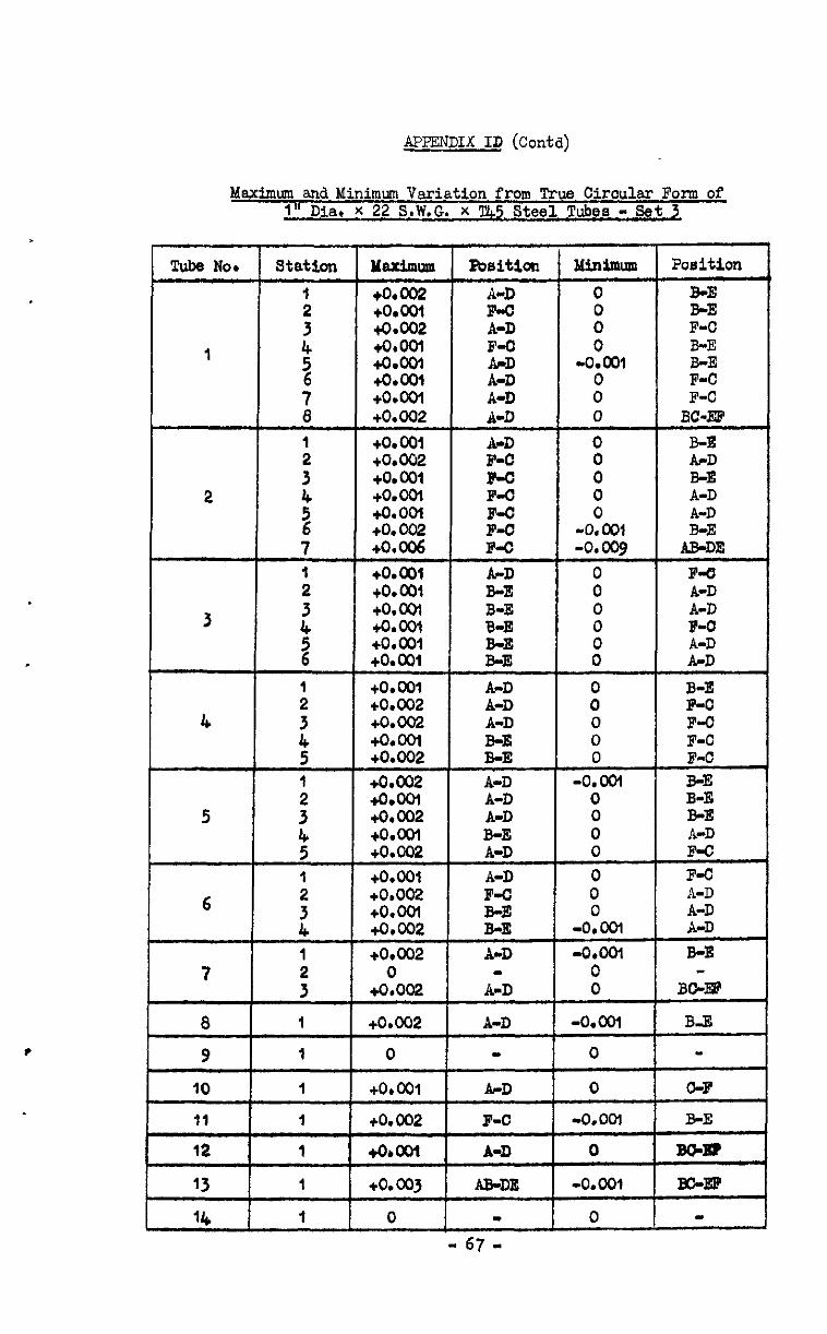
APPENDIX ID (Co&d)
Maximum and Minimum Variation from True Circular Form of 1" Dia. x 22 S.W.G. x 'l&5 Steel Tubes - Set 1
llinimlrm Rxition
0 BE B-E
t
: F-C 0 E-E
-0.001 0 E 0 F-C
T Stat5,on Y~um
+o.c02 +O.coI +0.002
232 +O.cQl +o.ool +0.002
BJeitbn Tube No*
0 1 BC-EE' A-D F-O F-o F-O F-C F-C F-o
+O.ool +0.002 +o.ca +o.ool +O.OOl +o. 002 +0.006
+O.ool +o. 001 +o.ool +o.ool +o.cm +O.ooI
+0.001 +0.002 +o.oG? +O.OOl +0.002
+0.002 +O.OOl +0.002 +o.ool +o.m?
+O.ooI +0.002 +o.ovl +0.002
+0.002
+0:002
+0.002
1
:
'; 6
0 A-D
: E 0” t; --I-- 0"
B-E PO
0 F-C 0 F-C
A-D B-E
4
B-E A-D :
! : if 1
:
1
A-D A-D B-E A-D
5 0 A-D 0 F-o 0 F-C 0 A-D
-0:OOl ;I; -0.001 B-E
0 0 B&J@
-o.ool B-E 0 m
0 C-F
-0.001 B-E
0 BWQ
6
7 A-D
8 1 A-D
1 0
+O.ool
+o.G02
A-D
F-O
4obool A-D
+o.c03 AB-DE
m 0 - 67 -
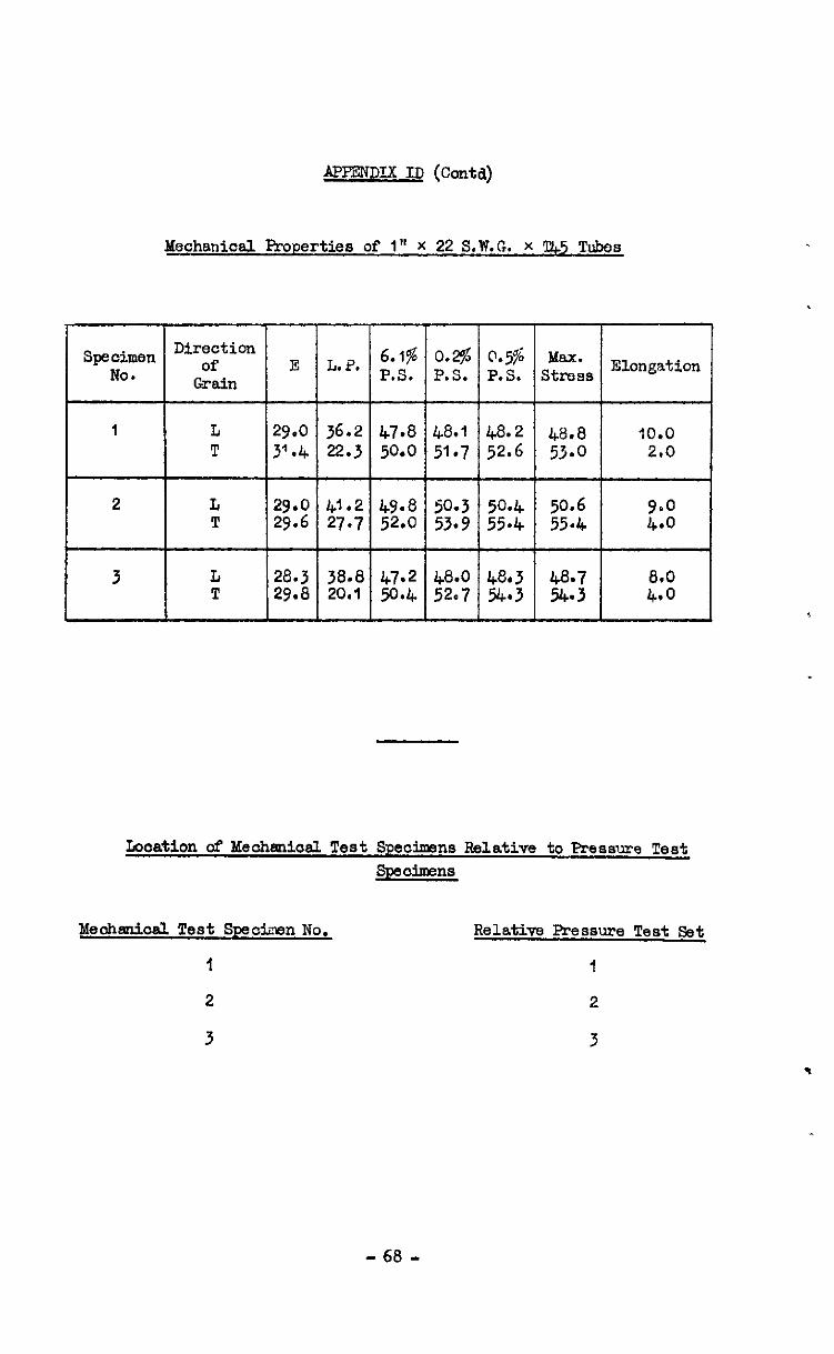
APPENDIX ID (Co&l)
Mechanical Properties of I" X 22 S.W.G. X T&5 Tubes
Direction Specimen of 6.1% 0.2$ 0.5s Max. NO.
E L.P. Grain P.S. P.S. P.S. stress E1onSation
I L 29.0 36.2 47.8 48.1 48.2 48.8 10.0 T 3'.4 22.3 50.0 51.7 52.6 53.0 2.0
2 L 29.0 41.2 49.8 50.3 50.4 50.6 T 29.6 27.7 52.0 53.9 55.4 55.4 ::z
3 L 28.3 3a.a 47.2 48.0 4a.3 68.7 T 29.8 20.1 50.4 52.7 54.3 54.3
lboation of Mechenical Test Specimens Relative to Pressure Test SpAnhens
Meohmical Test Specimen No. Relative Pressure Test Set
I I
2 2
3 3
- 68 -
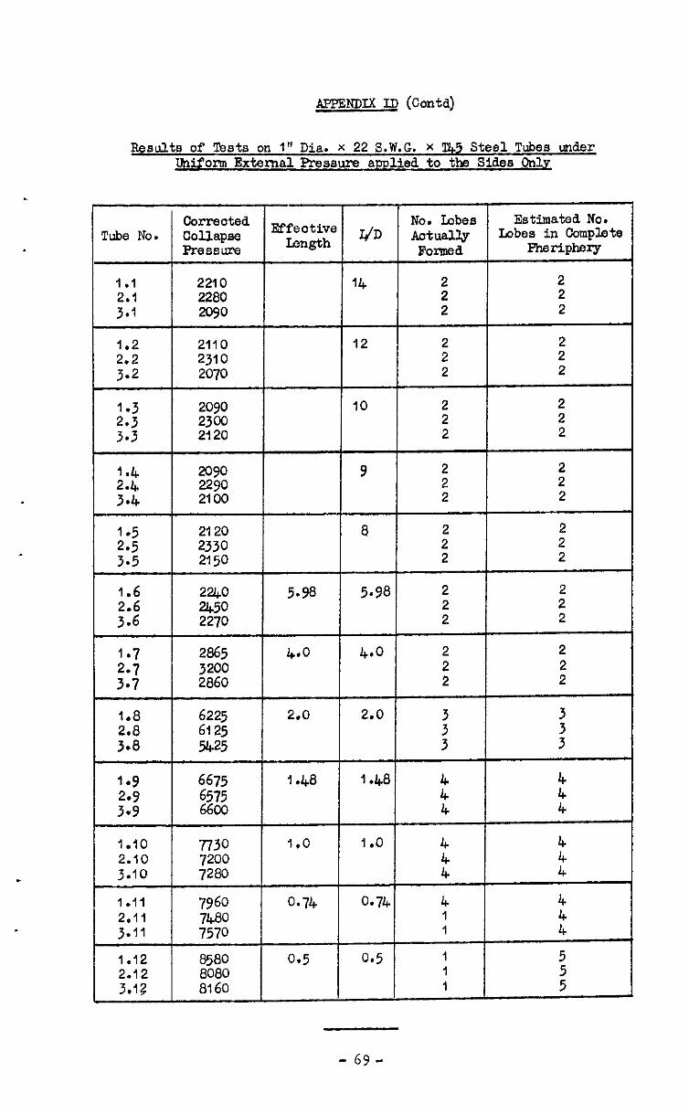
APFSNDIX ID (Contd)
Results of Tests on I" Dia. x 22 S.W.G. X !I&5 Steel Tubes under Uniform External Prwssure applied to the Sides Only
Correoted Tube No. Collapse
Pressure
Ef;;zhe qD &s$ Estimated No. Lobes in Complete
Formed -rj-PbrY
1.1 2210 14 ii 2
::: 2280 2090 2 2 2
1.2 2110 12 2 2
::; 2310 2070 2 2 2 2
1.3 2090 10 2 2
::: 2300 2120 2 2 2 2
1.4 2090 9 2 2
::"G 2100 2290 2 2 2 2
2: 2330 2120 8 2' 2 2
3.5 2150 2 2
1.6 2240 5.98 5.98 2
::6" %$ 2 2' 2 2
1-7 2865 4*0 4.0 2 2
::; 2860 3200 i 2'
::; 6125 6225 2.0 2.0 3 : 3.8 5425 3 3
I*9 g:: I .48 I .48 ;:;
: t 6600 4 4
1.10 7730 1.0 1 .o 4 2.10 7200 3.10 7280 k i
1.11 7960 0.74 0.74 4 4 2.11 7480 1 3.11 7570 I ::
1.12 8580 0.5 0.5 1 5
2.12 8080 1 3.12 8160 I I I :
- 69-
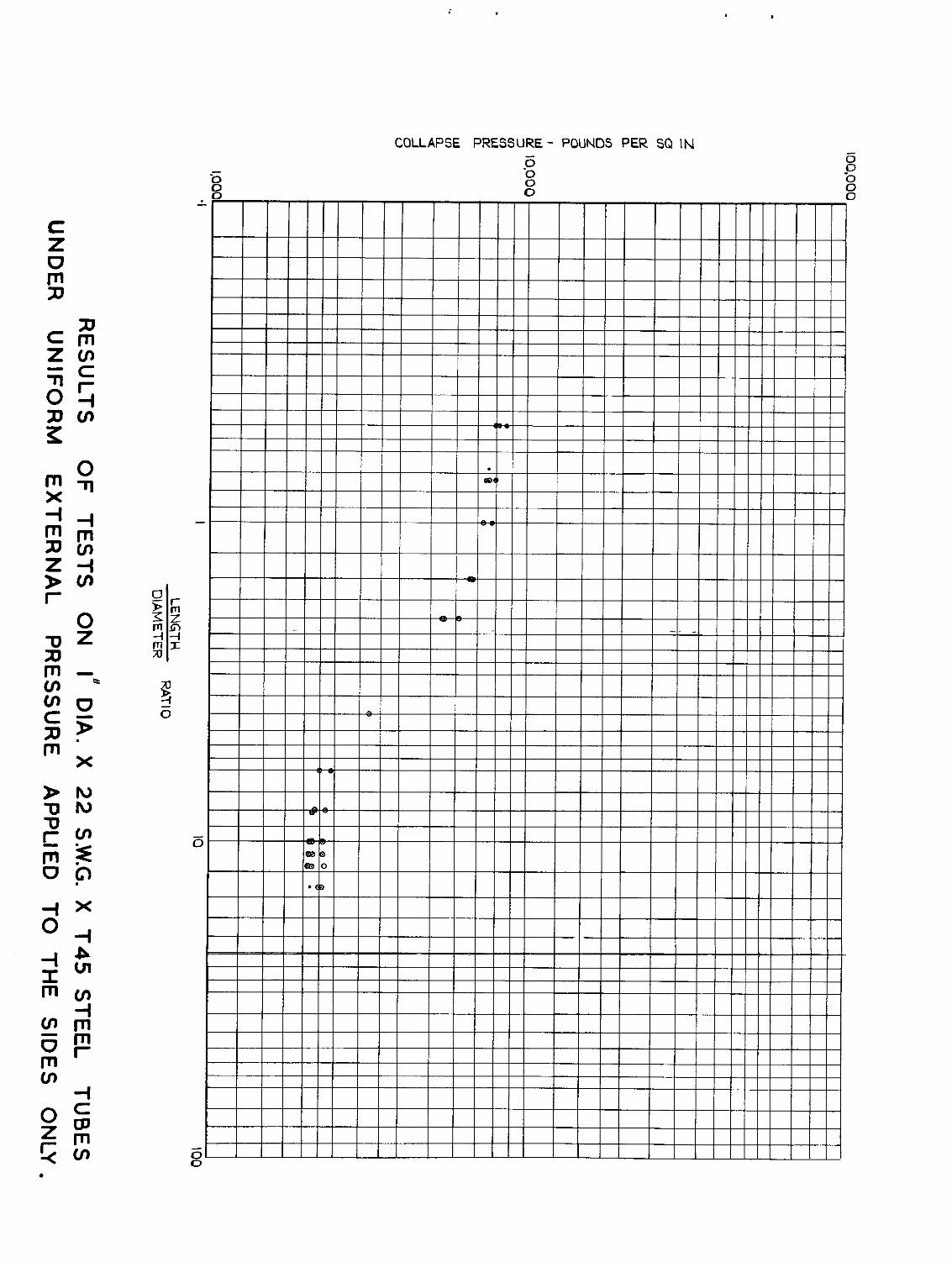

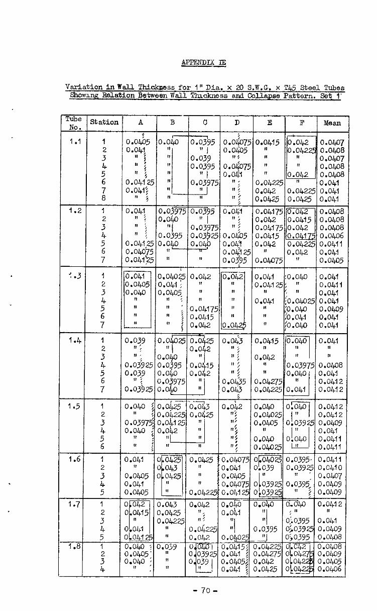
Variation inWall Thicknms for 1"Dia. x 20 S.F.G. x l'45 Steel Tubes Showm~? Rdation Between Wall Thickness and Collapse Pattern. Set 1'
Tube &
1 .I
1.2
:.3
1.4
1.5
1.6
- 1 .7
- 1.8
: ! %atiol:
I 2
;T 5 6
1
; 4 5
1
3” 4 5 1 2
z
A
0.0&5 0.041
II p I, :
! 11 ; 0.04{25 0.041~
II 5 ,
0.041 ,I ; 11 : 11 :
0.041:u 0.04075 0.041'25
0.041 0.0405 0.040
1
11 11 II !I 0.039
(1 ;
II ,
0.039 25 0.039 4, ; 0.03925
0.040 3
0.:397; 0.040 ;
0 : 11 i
0.041 0 0.0405 0.041 0.0.!@5 ~ O”42 i 0 0415 ~ f--l I,
0.041 ow 0.040 ?
d 0.0405' 0.040 ; II
C
C C
C 0
0 a 0
0
0 0 0 0 0
0 0 0 0
0 0’ 0
0 0 0
0
11
8, ; 0.0477: ; 0.0415
(I i 0.042
, .04Lx25 0.0
r ---- .0$25 o.a3 .04225 O.Ol;v .04125 11 .042 ”
1, H I, 1,
.a425 0.0425 043 *
R
0425 If I, I, II 0.0422
.043 0.042
.0&?.5 1’;
.04225 “5 II o.okz! ,, 0.042
5
, 5
,
i ( i ( (
( 1 C ( ( (
,I I,
0.04225 ” 0.041 0.042 0.04225 0.041
I I 0.0425 0.0425 0.041
i-i
0.042 0.04225 0.0411 II 0.042 0.041 0.04075 fn 0.040~
3.041 :o.oL& 0.041
0.0415 10.0417~ O.OWf
3.04125: fl 0.0411 I, I, 0.04f a.04l ;o.o4cJ25 0.041 I, ‘0.040 o.ol+o: 11 :0.041 0.041 I, to.040 0.041
o.iy Ipijq 1 o.gw 3.042 ” II 0.03975 II
iJ 0.040
1.04275 ” 3.04225 0.041
IV 0.04oE 0.041 0.041; 0.0412
I I
3.042 lo!ocol lo.0412
- 70-
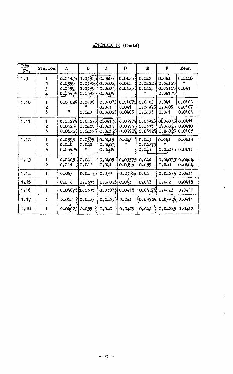
APPENDIX IE (C&d)
- 71 -
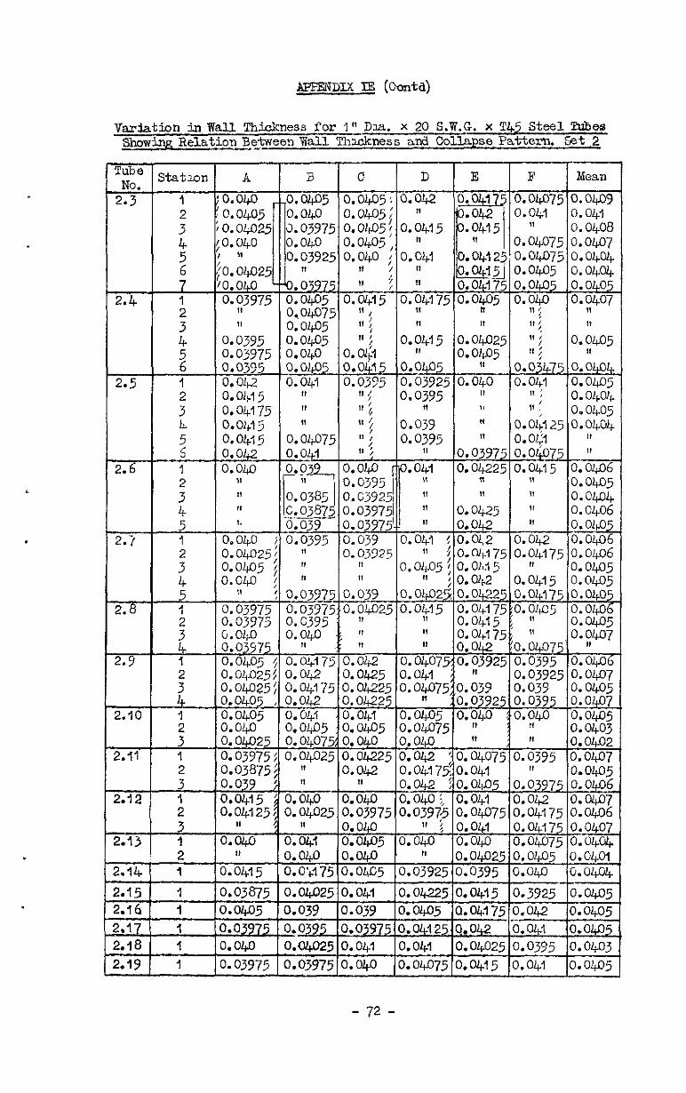
APFENDIX IFi (coda)
Variation inTfall !Chidmess for I" Daa. x 20 S.W.G. x T&5 Steel !&&es &&n,q Belatioa Br$ween Wall Thmkness and Collapse Paiiter% St 2
3tatmn
1
:
t
-t-
: 4 5 6 1
;
i 1 2
z 5 1
: 4 5 1
;
-+---
:
: 3 1
:
: 3 1 2 1
1
0.04175 " O.OL15 " 0.041; 0.0407:
--t 0.0 0.0-L 0.040 0.0%
,I f- i3
j
I! 0.0385 1, c.0387' .----ST !, 0.039
0.040 i 0.0395 0.04025: If o.oJ+pi ; " O.GlJ < "
: 0.0397F 0.63975 O.ojYT 0.03975 y3$5 c . O&O 0.03Y75 - 1, 0.0405 $ 0.0417: 0.0&025$ 0.042 ~.04025: 0.04175 l&o&? , 0.042
iagE 0.0&l
. o.ou5 I.04025 0.0407% f;;;W& 0.04025
I,
io39 i " __- I.0415 ; 0.0&o j.04125: 0.04025
I, / H
LOLO 0.0&.1
s j.04.05 0.039 I.0
LO3875 0.04025
0.0395 LO&O a04025
LO3975 0.03975
tl i lO.03Y I ” IO.Oi125!0.04Ok\ i II : ”
II : 0.0395
0.03975 O.O<l 6 0.040 - I8
0.040 0.0395
0.0$225 Of415 A-----i 0.0406 0.0405
0.0415 0.0405
- . L-_- - - ,
0.042 iO.04075dO.03925~0.0395 ln 0.03925 %$?I;
;.;3;, 3 5 0:040 yw; 5 -0:040 o 0.0405 o 407 0:0405 _,
I.0405 0.04075 ;; 3l 0.0403 1. OI+O 0.040 !I 0.0402 1.04225 0.042 to.04075 0.0395 0.04n7 LOG! 0.04l7~0.041
II 0.042 ~0.00405 0.63975 "0:$2 LOW 0.040 :, 0.041 0.042 0.0407 LO3975 LO40
0.03975 0.04075 0.04175 0.0406 " 5 0.041 0.04175 0.~407
LO@5 0.040 0.04.0 0.04075 0.0404. Loll.0 " n.oll.035 n.nLn5 0.01&l
- 72 -
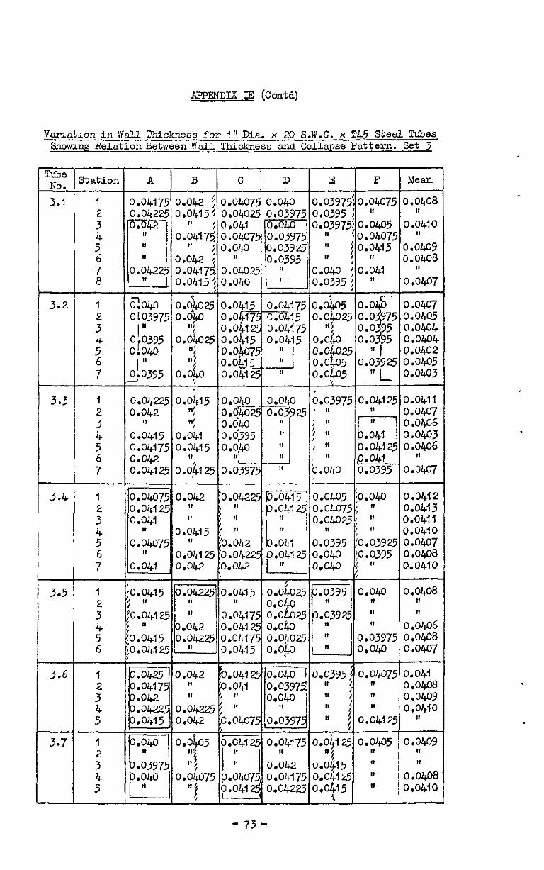
APFENDIX IE (Contcl)
Vam.r-tmn in Wall Thickness for 1" Dia. x 20 S.W.G. x !I!45 Steel Tubes shomng Re1otionBetweenWal.l Thickness and Collapse Pattern. Set 3
3.2
3.5
3.6
3.7
Z&ion
1 2
z 5 6
1 : 5”
B C D E F
0.042 : 0.0407 0.040 0.03975~0.04075
o.l$iu o.okl5- o.ol$- yJcJa O.O%5 111 f o.ob75 t
1,; o.&5 ::
25l
II I
0.0&o o.o4l- It o'oLo5 0.0392: o:o:&o5 " L
0.$15 /
0.040 0.040 o.oG- -
~.03975j0.041~ o.oj;v25 ' "
l--l "
o&o 11 o&v5 sl
j II 0 Ii-- .041
O.O!W " ; " , " P.04lZ
,I ~ O.&g5 "
II '0.040
10.041 0.0395
*
0.0415 o.oim5
0.64175 E '0.04125 0.040 : 11 It
0.042 ~.ow751/0.~
o.oJ.05 0.04125 0.04175 0.0405 I,, ', II II It 5
0.01075 I I 0.042
o.o+ II I
I, 0.0407s p.o4+
0.04175 O.Oljl5 o.ou25
II In Ia
11 / 4 0.04225 oJy5 If
Mean
0.0608 II
0.04io II
0.0409 0.0408
11 0.0407
O.OW7 0.0405 0.0404 0.0404 0.0402 0.0405 0.0403
0.0411 0.0407 0.0406 O.OW3 0.0406
11 0.0407
0.0412 0.04l3 0.0411 0.0410
:*:z 0:0410
0.0408 II I,
0.0406 0.0408 0.0407
0.041 0.04.@ o.owv 0.0410
I,
o.owv II I,
0.0408 0.0410
- 73-
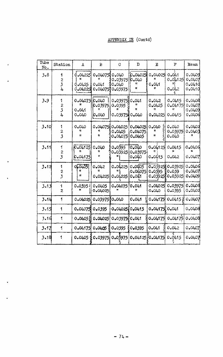
APPENDIX IE (Contd)
- 74-
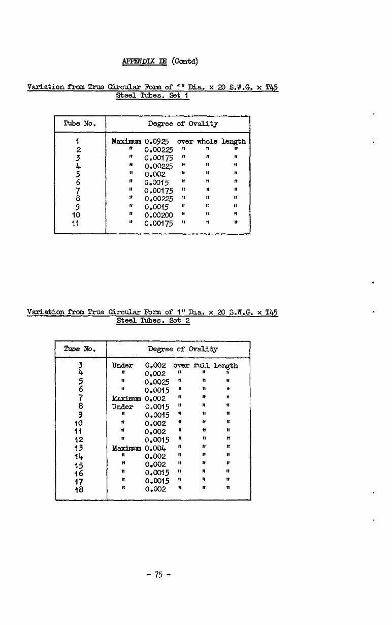
4zFmrlrY. IE (Cc&)
Variation from True GircuLar Rum of 7" Dia. x XI S.W.G. x Tti steel. Tubes. set I
!ime No. Degree of Ovality
1 : 5” ; 9”
IO Ii
0.0925 0.00225 0.00175 0.00225 0.002 0.0015 0.00175 0.00225 0.0015 0.00200 o.ca75
Variation from True Circular Form of I" ma. x 20 S.W.G. x 'I45 steel. Tubes. set 2
!haDe No. DepeofoP&ty
z Under 0.002 over f-a-13- lmgth
" 0.002 II w 11 5 "
76
0.00~ " " " 1, 0.0015 fl "
lbximan 0.002 In ; 0 Under
9" It 0.0015 " " " 0.0015 " l" R
IO n 0.002 " n " II (I 0.002 ol 8 " 12 " 0.0015 tl fl " 13 Maxjnaml0.004 Ia " " 44 II 0.002 It fi " :2 II 0.002 IQ " It
$9 0.0015 It " Is 17 " 0.0015 " " " 18 II om2 9l " "
- 75 -
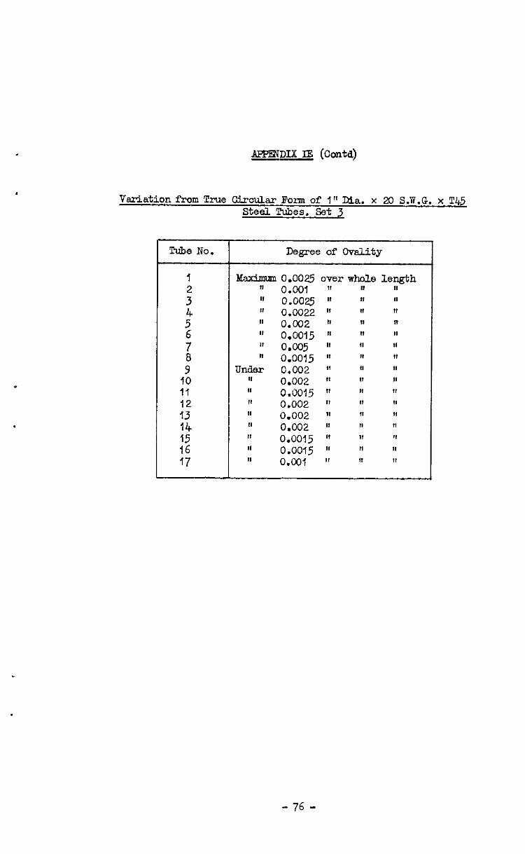
APPENDIX IE (Contd)
Variation from True Circular Form of I" Dia. x 20 S.W.G. x T45 steel Tubes. set 3
:3” :4 f6 17
Degree of Chdity
ldsdmm 0.0025 over whole length 11 0.001 " " " II 0.0025 " " " ,I o.CO22 " " R II 0.002 tl fl " I, 0.0015 nl " Is II o&)5 II II If n 0.0015 'I " "
under 0.002 fl " Ia II 0.002 " " " 4, 0.0015 " " 7' I# 0.002 " " " 11 0.002 " I' " II (J&32 II II rt I, 0.0015 " " " I, 0.0015 " " 1' II o.a, II 11 II
- 76 -
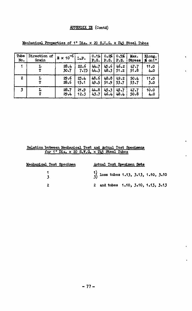
ApmmDIx m (conta)
Meohanioal Pmrerties of 1" Ma. x 20 S.W.G. x LT.45 Steel Tubes
RelationbetweenMeohaniosJ. Test and Aotual Test Spscd.u~ns for f" Ma. x 20 S.W.G. x !I'&,5 Steel lkbes
hleohsnio8l Test Specimen
:
2
Adad Tcst Speaimen Set8
: 1 l.oss tubes 1.13, 3.13, 1.10, 3.10
2 snd tubes 1.10, 3.10, i.13, 3.13
- 77-
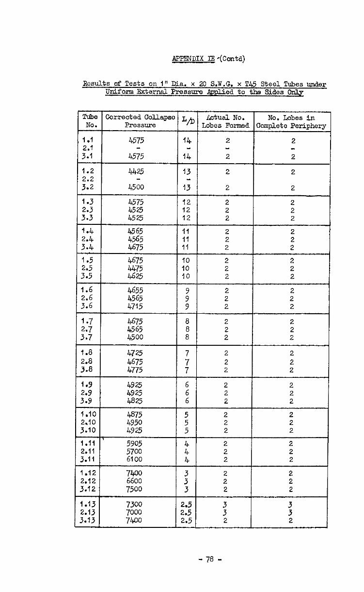
APPlT3DIX IE-(Contd)
Results of Tests on I" Dia. x 20 S.W.G. x T45 Steel Tubes under Uniform Zxternsl Pressure &plied. to the Sides Cdy
Tube Corrected ColAapso L/D J’ktlld NO. No. Lobes in NO. Pressure Lobes Formed Complete Periphery
I .I 4575 14 2 2
::: 4575 14 2 2
1.2 442.5 13 2 2
::E 4500 13 2 2
1.3 4575 12 2 2 4525 12 2 2 4525 12 2 2
I I I I I
1.4 I I
4565 2 I 2 I 2.4
1.8 4725 2 2 ::"8 t% 7 : 2 2 2 2
Is9 4925 6 2 2 ::; I 4925 68.3 i 2 2 2 2
I .I0 4875 2 2 2.10 4950 z 2 2 3.10 4925 5 2 2
I 3.11 2.11 I 5700 6100 2 2 I 2 2
1.12 2 2.12 ZE 2 ; 3.12 7500 3 2 2
1.13 7300 2.5 2.13 7000 2.5
; 3 3
3.13 7400 2.5 2 2
- 78 -
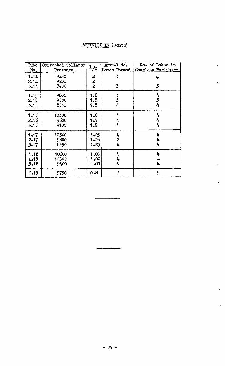
APPEXDIX II3 (Cc&d)
I ,18 1060~~ I .oo 4 4 2.18 10500 I ,oo 3.78 VW 1.00 4” 4”
2.19 9750 0.8 2 5
- 79 -
Variation in noll thickness for 1" dia. x 17 S.W.G. x !C45 Steel Tubes showinn relation betmen wall thickness and collnpse p&tern. Set I
Tube No.
1.1
f.2
1.3
I.4
1.5
I.6
1.7
1.8
1.9
1.10
ltatiol
1
; 4 5
:
1
: 4 5
76
1
:
i
1 2
l 5
1
: 4
1
:
1
:
1
1
1
A B C D E I
I I I I 0.05875 0.0595 0.059 0.05825 0.0577:
11 " " 0.0585 0.0582:
o.ola5 0.0;~ 0.05925 0.059 0.05025 0.0585 0.0577 0.05a5 0.058 0.0;95 0.0595 0.0595 0.0582, 0.05625 0.0585 0.05875 0.05925
0.0;975 0.0;975 "
:*z; . ” 0.060 0.0;975 0.060 0.055 0.05525 0.0555 0.05575 0.05625 0.057
0.03525 0.059 0.0625 0.062 n 1, I, II t? I, 0.06225 *
0.05875 0.062 "
?I 4
0.06075 0.06425 0.06075 0.0565 0.0545 0.060 0.06025 0.05625 "
" pcg25
* 0.06125 0.05675 II I, 0.06125 0.0575 0.0;47!
0.05925 " 0.06125 0.05725 0.055
0.05475 0.0585 0.0625 0.063 0.0592!
0.0545 0.05825 0.054 0.058 O.Of275 0.0$325 o.o;* 0.0545 0.05825 0.0625 " 0.0592:
0.0635 0.060 0.055 11 ,t 0.0555
o.op5,0.0575 II " 11
i
II 0.054 fo.o572!
0.0605 0.0605 0.0605
0.0555 0.054 0.0565 0.061 0.0555 :: 0.057 0.0617: 0.05575; 0.05675 0.0615
0.054 i 0.0555 0.0605 0.0635 0.062
0.0575 0.$35 0.055 0.060 0.064
LO+75 , 0.05475 0.05925 0.064 0.063
--T-pE
0.06125 0.0587 0.0615 0.0587
0.06125 0.06075 o.oia7 0.060 0.0586
0.05825 0.0587 0.059 0.0588
;.;;~5 0.0588 " 01057 0.058$ 0.058 0.0587
0.056 o.o!jaa 11 0.0504
,0.0255 0.0586 0.0587
0.05575 "
0.05525 0.0588 0.05475 0.0588
,I 0.0587 II II
0.042 0.0587 0.0&25 0.0587 0.0588
0.0635 0.0585C 0.06375 0.0587
11 0.05a7
0.0575 0.0588
0.06225 0.0587
0.05775 0.0588
- ao-
!J'PEXDIX I!? (Contd)
Variation in ml1 thiclmess for f" dia. x 17 S.W.G. x ‘I!45 Steel Tubes showing relation between wall thickness an3 collapse pattern. Set II
lbbe Station k B C D E F Mean NO.
2.1
2.2
2.3
2.4
1 0.05875 0.05725 0.057 0.05825 0.060 0.060 0.0585 0.05825 0.0;75 0.05725 0.05875 ” 0.060 0.0586 0.05875 0.057 0.058 0.0555 0.0584
4 0.059 0.05725 0.0575 0.0595 0.060 0.0583
2 0.0595 0.05925 0.05775 0.058
“o.;;y
O:Q565 0.05725 0.0575 0.0595 0.05875 0.06025 0.0595 0.0583 0.05850 7 0.05975 ” 0.05675 0.05725 0.05925 0.06025 a 0.060 0.05825 0.05625 0.057 0.059 0.060
;.~38~ .
1 0.05625 0.05675 0.0587; 0.06025 0.05975 0.0575 0.0582 0.0555 0.0565 0.059 :,
” ! 0.0605 0.05975 0.05725 0.0581
0.05525 0.05575 0.06075 0.06025 ’ 0.0580 0.0555 0.0555 0.05825 0.06025 0.060 0.0575 0.0578 0.05525 ” 0.0585$ 0.061 0.0605 0.058 0.0581 0.05575 0.05575 0.05825 ” 0.061 0.075 0.0584 0.0555 0.05525 0.05775 0.06@ 0.06125 0.0581
1 0.0565 0.054 0.056 1 0.060 0.063 0.0605 0.0583 0.05675 0.05425 n
” ; I 0.06025
0.057 0.05425 ” 1: 0.061 0.0585 0.06125 0.0586
4 0.05725 0.05475 0.05625 ” 0.06275 ” 0.0587 5 0.05775 0.055 0.05575 0.060 n 0.0588 6 0.0575 0.05475 0.05575 0.05975 0.0625
;: 0.0586
1 0.05725 0.06925 0.06275 0.0595
2.5 0.0625 0.060 0.057 40.0~45 0.0565 0.0585 11 0.06125
0.06275 0.0615 0.057251 0.05625 0.0586
0.0587 4 I’ ” ” 0.0587
2.6 I 0.061 0.0565 0.05475 0.063 0.0587
0.057 0.05425
0.05675 Q/%3;
0.056 5 0.0565 0.054 0.05625 010605 O.Oi25 “o::%
2.7 1 0.062 0.059 0.05525 0.05825 0.0615 0.0586 0.06175 0.0586 0.0615 0.0582
2.8 1 0.05725 0.061 0.06175 0.0595 0.05;75 0.05475 0.0583
2.9 1 0.0555 0.05825 0.06125 0.06125 0.05875 0.05625 0.0585
2.10 1 0.0615 0.05975 0.05675 0.0$55 0.0575 0.06025 0.0585
2.11 I 0.06125 0.0605 0.05825 0.056 f 0.0565 0.05925 0.0586
- 81 -
AFPENDIX IY (C&d)
Variation in wall thickness for 1" dia. x 17 S.W.G. x T45 Steel Tubes Showinn relation between wall thickness ad. oollawe pattern. Set III
3.2 1
i 4
2 7
3.3 1
:
:
3.4 1
; 4 5 6
3.5 1
: 4 5
3.6 1
:
3.7 1
:
3.8 i
3.9 1
3.10 1
D E I? Mean I I I I
0.0560 0.0555 0.0552 0.0555 II
0.058 0.0585 0.0585 0.05875 0.05825 0.0585 0.059 0.059 Cp5~5 0.0;95
0:0595 "
0.06075'jO.O50
0.060 j "
0.0585 0.060 0.06025 0.0586 0.05825 ' 0.0585 o ok o 0;86
II 0.0;95 0105975 0:05e4 ,t I, 0.0595
O.Oi875 II " 0.05975 0.05925 0.0~8 0.0588
0.059 0.05875 0.0585 0.05875 0.0585 "
ES";2
0.059 0.059 0.059 010587 0.0585 0.058 0.058 0.0585 o;ojv- O.Oj85 0.0585 0.0589
11 0.05825 0.058 0.0590 II 0.05775 0.0585 0.0588
0.056 0.05675 0.0595 0.0588 0.05625 0.05725 " 0.0586
II 0.057 0.05925 0.0586 0.0565 0.05725 0.0595 0.0587
O-O;675 0.0;70 ::"o:i;5 0.0;86
0.063 I 0.06~ I I I 10.0586 0.06125 0.0%5 0.053 -
_ ._ 0.062 0:06&25 " 0.0555 0.0525 0.0585C 0.0615 " 0.061 It 0.05275 0.0584 II II 0.06175 0.0565 II 0.064
",.06;5 .
0.056 ;.;;;25
0105325
;.;;z
0.062 0.064 0.05625 010587
0.0625 0.064 0.06025 0.0555 0.0565 0.0587 II 0 061
0.0:,75 0106025 0.056 0.05375 0.057 0.0590
0.062 0.0552 0.0586
0.0595 0.0547$0.054 0.06325 0.0587 II 0.055
" 0.0;375
0.028 O.Of25 0.0635 0.0587
0.060 " 0.063 0.06325 0.0588
0.05925 0.063 0.06325 0.059 0.02425 0.05&5 0.0589 1, I 0.0635 0.06225 0'05755
i I- 0.0589
0.06075 0.061 0.059 0.0588
- az-
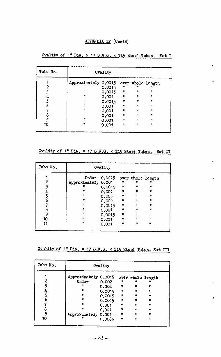
APPENDIX IF (Contd)
Ovallty of 1" Dia. x 17 S.W.G. x T45 Steel Tubes. Set I
Tube No.
1 : ; ! 8 9
10
Appmdmately 0.0015 II 0.0015 II 0.0015 If 0.001 1, O.OOl5 I, 0.001 I, 0.001 n 0.001 n O.cnl 8, 0.001
overw&~lelength II 1, I,
Tube No. Ovality
1 Under 0.0315 over Mole 2
length Approximately 0.001 " If I(
i
11 o.cn15 ‘1 ‘1 ” 1, 0.00, ,I 11 II
2 11 ” 0.005 0.002 ” ol ” 11 ” "
i
,t 0.0015 ” ” ” ” 0.001 ” ‘1 ”
9 ” 0.0015 ” ” ” 10 n O.col w fl n 11 II o.-JJ, II I8 II
Tube No. OVality
I Appmximately 0.0015 over whole : Under
length 0.002 " u "
n 0.002 (( n " 4 ” 0.0015 ” ” ” 5 ” 0.0015 fl fl m 6 ” 0.0015 n ” ” 7 ” 0.001 It H " a n 0.001 n H v 9 Approximately 0.001 w N 11
10 " 0.0065 n n 11
Ovality of 1" Dia. x 17 S.W.G. x T45 Steel Tubes. Set II
0"mlit.y of 1" Dia. x 17 S.Y.G. x T45 Steel Tubes. Set III
-83-
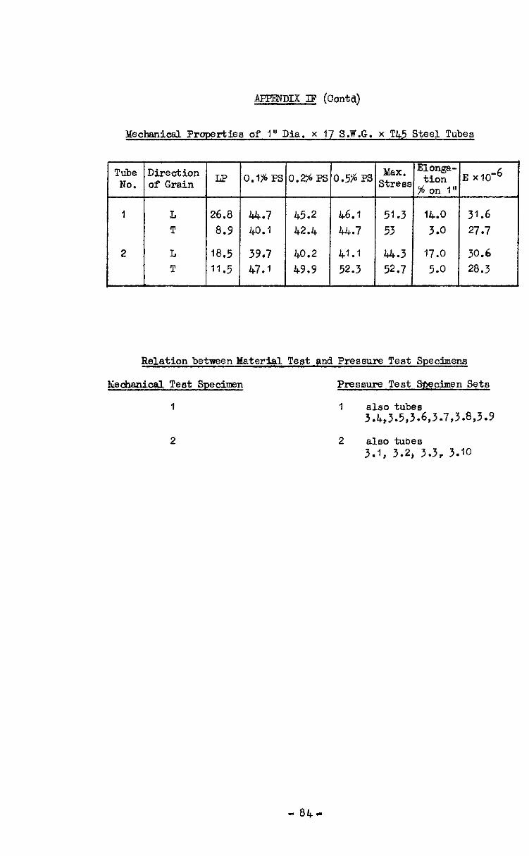
AFFF8IDI.X II? (contd)
Q rties of 1" Dia. x 1 S.W.G. x T Steel Tubes
, Tube Direction LP O.l%PS 0.2%PS 0.5%Ps ,t:;,
Elonga-
NO. of Grain tion E x~O-~ % on 1"
1 L 26.0 a.7 45.2 46.7 51.3 14.0 31.6 T a.9 40.1 42.4 44.7 53 3.0 27.7
2 L 18.5 39.7 40.2 41.1 44.3 17.0 30.6 T 11.5 47.1 49.9 52.3 52.7 5.0 20.3
Relation betweenMaterial Test +ufi Pressure Test Specimens
biechanical Test Specimen Pressure Test Specimen Sets
I I also tubes 3.4,3.5,3.6,3.7,3.%3.9
2 2 also tubes
3.1, 3.2, 3.3, 3.10

Results of Tests on 1" Dia. x 17 S.W.G. x l'45 Steel Tubes under Uniform Fxternal Pressure Applied to the Sides onIQ
Tube NO.
1.1
:*: 1:2
::2' 1.3
::; 1.4
32:: 1.5
;:;
216 3.6
2: 3.7 1.8
::: 1.9
t-99 1.;0 2.10 3.10 2.11
Collapse PF3SSlU-8
113oo ?I200 11600 12cKxl :I200 11500 12300 1wo 1'750 12800 11800 1'600 12500 11700 12100 13400 11800 12400 13250 11950 12200 13900 126oo 12750 13650 13000 42900 13500 l3@xJ Iboo0 13200
z-- D -
14 " *
12 ” ” 10
"
;; II
69 II
l n
I; n
"
2 II
.I
25
.9 '. 9
::
No. Lobes fOIUk?d
2 )t
R
”
II
”
n
,I
n
”
11
n
”
n
1,
II
II
”
11
n
II
;
2
;
2
i
2
EstimatedNo. I&es in Complete Periphery
2 ”
”
I(
II
”
11
11
II
II
”
”
”
11
”
11
n
”
”
”
”
;
2 ”
3 2 2 3 I, 2
Attached: IQ. S.M.E. 75082/R
- 83 -

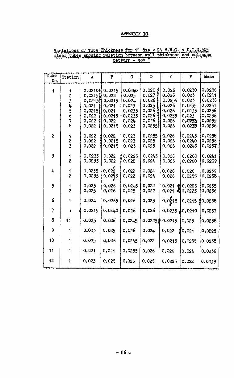
Variations of Tube Thickness for I" dia x 24 S.W.G. x D.T.D.a steel tubes showinn relation between wsll thickness and oollsn~e
pattern - set I
FiG No.
1
2
3
4
5
6
7
8
9
IO
11
12
#tatioI:
1
: 4
2
;I
1 2 3
1 2
I 2
1 2
1
1
II
1
I
1
I
-7
0.0210! 0.02151 0.0215, 0.021 j 0.0215; 0.022 1 0.022 1 0.022 j
0.022 0.022 0.022
0.0235 0.0235
0.0235 0.0235
0.025 0.025
0.024
0.0215
0.025
0.023
0.025
0.021
0.023
B --c 0.0215 0.0240 0.022 0.025 0.0215 0.024 0.021 0.023 0.021 0.0235 0.0215 0.0235 0.022 0.024 0.0215 0.023
0.022 0.0215 0.0215
0.022 0.022
o.o& 0.02j5
0.026 0.026
0.0265
0.0240
0.026
0.025
0.026
0.021
0.025
0,023 0.023 0.023
0.0225 0.022
0.022 0.022
0.0245 0.025
0.026
0.026
0.0245
0.026
0.0245
0.0235
0.026
D
0.026 0.027' 0.026i 0.025 j ;.g"6 ~
01026 0.0255
E F
0.026 0.0230 0.026 0.023 0.0255 0.023 0.026 0.0235 0.026 0.0235 0.0255 O&23 0.026 Q.OZS5 0.026 0.02.B
0.0255 0.025 0.025
00:0Y
0.024 0.024
0.022 0.022
0.023
0.026
0.0225
0.024
0.026 0.0245 0.026 0.0240 0.026 0.0245
0.026 0.0260 0,026 0.0260
0.026 0.026 0.026 0.0255
0.021 !
0.0225 0.021 0.0225
0.0$15 0.0215
0.0235 3:0.0210
0.0215 0.023
0.022 [1:0.021
0.022 0.0215 0.0235
0.026 0.026 0.024
0.025 0.0225 0.022
0.0236 0.0241 0.0236 0.0231 0.0236 0.0236 0.0239 0.0236
0.0238 0.0236 0.0257
0.0241 0.0239
0.0239 0.0238
0.0235 0.0236
0.0238
0.0237
3.0238
0.0225
3.0238
3.0236
1.0239
- e6 ”
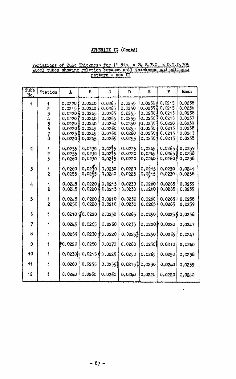
mmxx 12 (cored)
Vsristians of Tube Thickness for I" dia. x 24 S.W.G. x D.T.D.302 steel tubes showmz relation between wall thickness and oolla~se
pattern - set II
iis No.
I
2
3
4
5
6
7
8
9
IO
II
12 -
Station A B
3.0220 0.0240 3.0215 0.0240 0.0220 0.0245 0.0220 0.0240 0.0220 0.0240 0.0220 '0.0245 0.0225 0.0245 0.0220 0.0245
0.0255 0.0230 0.0255 0.0230 0.0260 0.0230
0.0260 0.02 0 d 0.0255 0.02,5
0.0245 0.0220 0,02l+5 0.0220
0.0245 0.0220 0.0250 0.0220
0.0210 0.0220
0.0245 0.0265
0.0255 0.0230
0.0220 0.0250
0.023Of 0.0215
0.0260 0.0255
0.0240 0.0260
0
0.0265 0.0265 0.0265 0.0265 0.0260 0.0260 0.0260 0.0265
;.:OZ;
0:02j5
0.0250 0.0240
0.0215 0.0215
0.0210 0.0210
0.0250
0.0260
0.0220
0.0270
0.0225
0.0235;
0.0260
D E F hban
LO255 0.0230 0.0215 0.0238 I.0250 0.0235 0.0215 0.0236 3.0255 0.0230 0.0215 0.0238 3.0255 0.0230 0.0215 0.0237 LO250 0.0235 0.0220 0.0239 0.0255 0.0230 0.0215 0.0238 0.0260 0.0235 0.0215 0.0243 0.0255 0.0230 0.0215 0.0238
0.0225 0.0245 0.0220 0.0245 0.0220 0.0240
0.0220 o.oi15 3.0225 0.0;15
0.0230 0.0260 0.0230 0.0260
0.0230 0.0260 0.0230 0.0265
3.0265 0.0250
0.0235 0.0220
0.0225$ 0.0250
0.0260 0.0230
0.0250 0.0265
0,0215# LO230
0.0240 0.0220
0.0230 0.0241 0.0230 0.0238
0.0265 0.0239 0.0265 0.0239
0.0265 0.0238 0.0265 0.0239
0.0225~iO.0236
0.0220 0.0241
0.0265 0.0241
0.0210 0.0240
0.0250 0.0238
0.0240 0.0239
0.0220 0.0&o
- 87 -
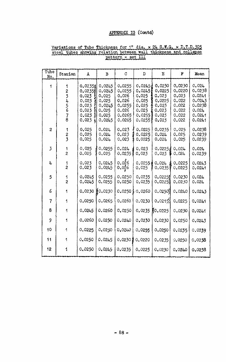
AFPENDM IG (Contd)
Variations of Tube Thickness for I" dia. x 24 S.Pf.G. x D.T.D.302 steel tubes showing relation between wall thiokness and collapse
pattern - set III
TG &
1
2
3
4
5
6
7
8
9
10
II
12 -
Station
I 2 3
1 2
I 2
1 2
1
I
1
I
1
1
I
-
I
,
I
c
A
0.023~ 0.023: 0.023 0.023 0.023 0.023 0.023 0.023
I B -
~ 0.0245 ~ 0.0245 ;0.025 ~ 0.025 ~ 0.0245 So.025 i 0,025 ,0.0245
0.025 0.024 0,025 0.024 0.025 0.024
0.025 i 0.0255 0.025 0.025
0.023 0.023
0.0245 0.0245
0.023C
0.0250
0.0245
0.0260
3.0225
3.0250
3.0250
0.0245 0.0245
0.0255 0.0255
fO.0230
0.0265
0.0260
0.0250
0.0230
0.0245
0.0245
0.0$6 0.0255 0.024 0.0#6 O.C25 4 0.0235
0.0225 0.0225,
0.0250,
0.0225
lo.0225
0.0230
0.0250
0.0235
0.0230
F
0.0230 0.024 0.0220 0.0238 0.023 0.0241 0.022 0.0243 0.022 0.0238 0.022 0.024 0.022 0.0241 0.022 0.0241
0.025 0.025 0.025
0.024 0.024
0.0225 0.0225
0.0230 0.0250
0.0240
0.0225
0.0230
0.0250
0.0235
3.0250
0.0240
0.0238 0.0239 0.0239
0.024 9.0239
0.0243 0.0241
0.024 0.024
0.0243
3.0241
3.0241
0.0243
3.0239
1.0238
3.0238
- 88 -
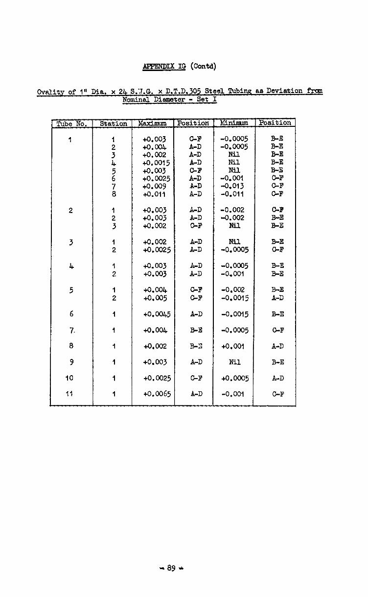
laE'ENDIX IO (Contd)
0vtiit.v of 1" Dia. x 24 S.7.G. x D.T.D.305 Steel Tubi!% as Deviation Apep Nominal Diameter - Set I
Tube No.
1
2
3
4
5
6
7.
8
9
10
11
Station
I 2 3
I 2
1 2
1 2
1
I
I
I
I
I
Position
+0.003 to.004 +0.002 +0.0015 +0.003 +o. 0025 +o.wv 4.011
TGczzz - C-F A-D A-D A-D
E A-D A-D
-0.0005 BE -0.0005 B-E
Nil B-E Nil B-E Nil B-E
-0.001 GF -0.013 GF -0.011 GF
+0.003 A-D -0.002 GF +o. 003 A-D -0.002 B-E +0.002 GF Nil B-E
+o. 002 A-D +0.0025 A-D
+0.003 A-D +0.003 A-D
+0.004 GF +a005 GF
+o .0045 A-D
+0.004 B-E
+0.002 E-9
+0.003 A-D
+O. 0025 GF
+0.0065 A-D
Nil -0.ooo5
-0.0005 -0.001
-0.002 -0.0015
-0.0015
-0.0005
+O.OOl
Nil
+0.0005
-0.001
B-E GF
B-E B-E
B-E A-3
B-E
GF
A-D
B-E
A-D
GF
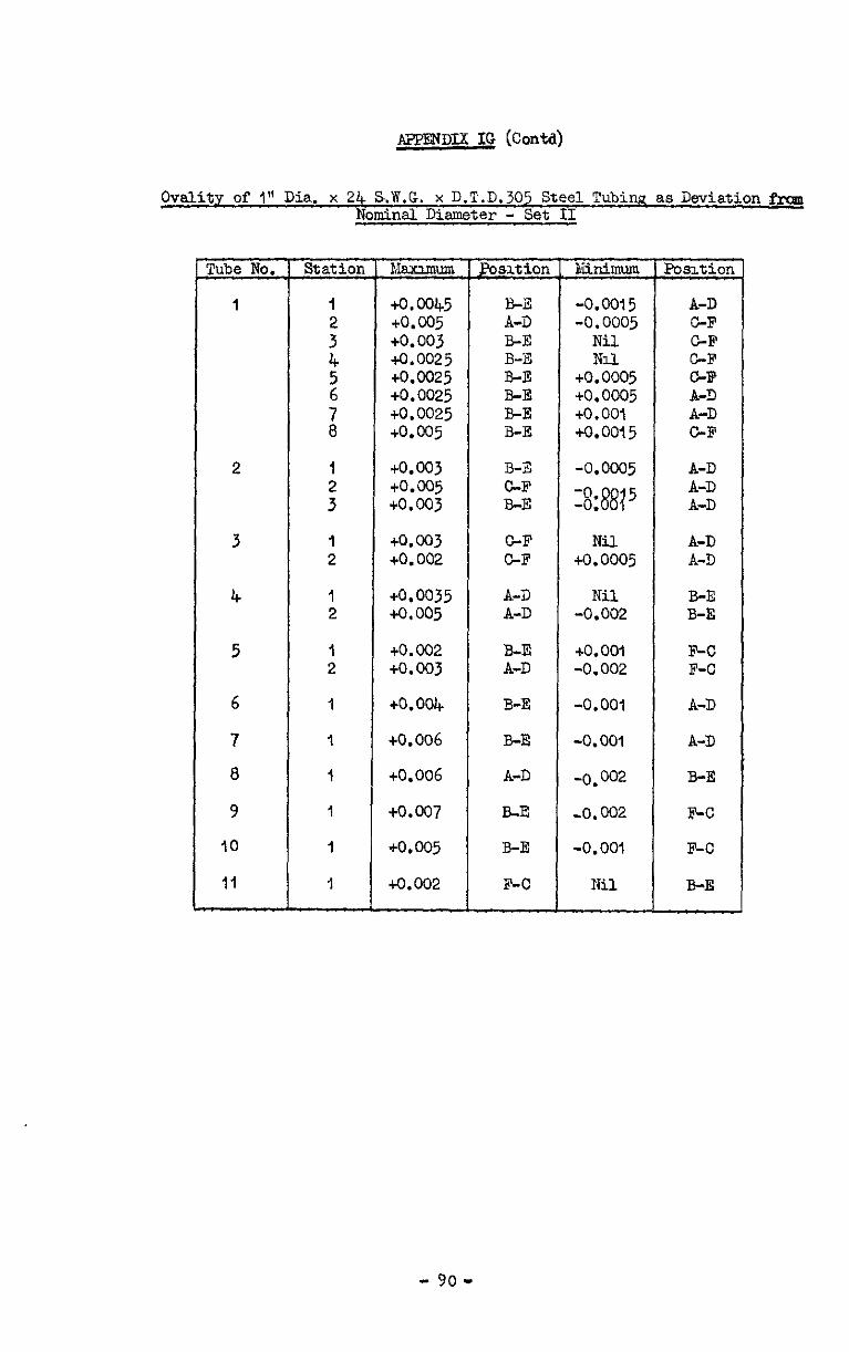
APPENDLX IG (Con@
OvaPity of I" Dia. x 24 S.1.G. x D.T.D.305 Steel Tubing as Deviation &.Q Nominal Diameter - Set II
Tube No.
1
2
3
4
5
6
7
8
9
10
11
Station
1 3" 4
2
z
I
:
1 2
I 2
hlaxlmum
to.0045 to.005 +0.003 to.0025 to.0025 +0.0025 +0.0025 to.005
+O.ooJ to.005 +O.ooJ
to.003 to.002
+o.o035 to.005
to.002 to.003
to.004
to.006
+0.006
eo.007
to.005
+0.002
psit ion
B-F8 A-D B-E B-E B-E B-E B-E B-E
BiTi G-F B-E
C-F C-F
A-D A-D
B-E A-D
B-E
B-E
A-D
BE
B-E
F-C
skinimum Pos-rtion
-0.0015 A-D -0.0005 GF
Nil CF NiL G-F
to.0005 OF to.ooo5 A-D +O.OOl A-D to.0015 C-F
-0.ooo5
X8815
Nil to.0005
Nil -0.002
to. 001 -0.002
-0.001
-0.001
-0.002
-0.002
-0.001
Iii1
A-D A-D A-D
A-D A-D
B-E B-E
F-C F-C
A-D
A-D
B-E
F-C
SC
B-E
- YO-
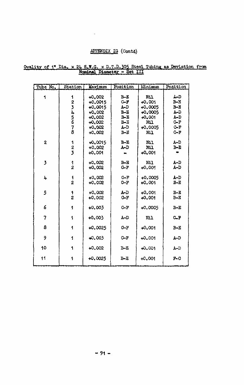
APFENDIX IG (Contd)
Ovality of t* Dia. Y 24 S.W.G. x D.T.D.305 Steel Tubina as Deviation Fran Nculina M8m8ter - set III
2
3
4
5
6
7
8
9
IO
II
7t?izG
1
:
%
;I
: 3
:
:
:
1
1
I
I
I
I
Position
+0.002 B-E +0.0015 GF +o.om5 A-D +0.002 BE +0.002 B-E +0.002 B-E +0,002 A-D +0.002 B-E
+o.m5 +0.002 +o.ooi
+0.002 +0.002
+o. 002 +0.002
+o. 002 +0.002
+0.003
+%Qo3
+0.0025
4.003
+0.002
22: m
B-E GF
C-F GF
A-D GF
GF
A-D
GF
GF
B-E
+0.0025 B-E
3JhimLm
Nil +o.ool +o.occl5 +o.m5 +o.ooi
+0%05 Nil
Nil Nil
+O.OOl
+o%
+o.cno5 +O.OOl
+o. 001 +o.ool
+0.0005
Nil
tO.001
+o.OOl
+o.ooi
+&WI
LPD E-E B-E
E GF GF GF
A-D B-E m
A-D A-D
A-D B-E
B-E B-E
E-E
CLF
E-E
A-D
A-D
F-O
- 91 -

APPENDIX IG (Contd)
hkdmxi.cel properties of I" Dia. x 24 S.W.G. x D.T.D.3'35 Steel Tubing
Tube Rimction E x 0.1% 0.q 0.5% Max. No. of Grain an-6 LQ* P.S. P.S. P.S. Stress zFi"
I L 29.0 21.8 34.8 35.2 35.7 36.f 5.0 T 29.6 it.6 34.6 36.1 36.9 37.0 1.0
Relation betweenHeohanioal. srdFressure Test @eomens
sin!3 all pressure test ,spedmens ‘RBre out frcua one length of tube, the resultsquoted above mire ~pliedin all oases.
"92"
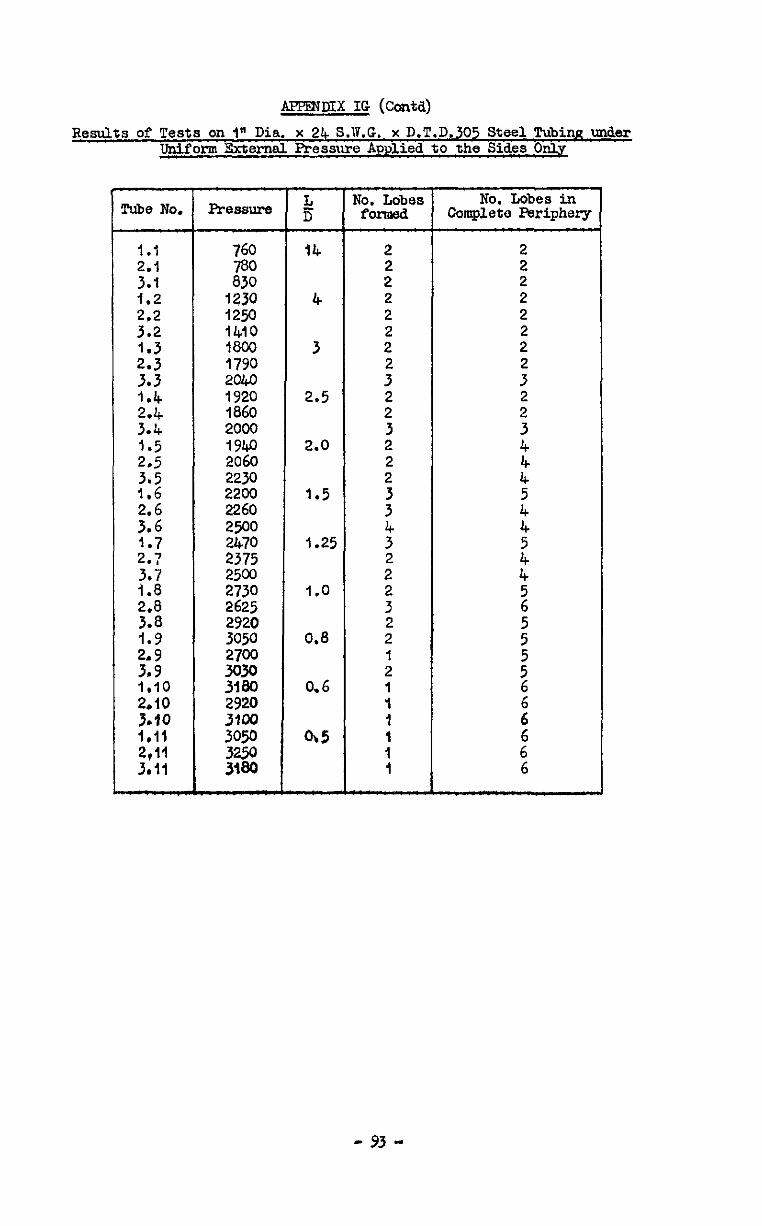
APF'ZNDIX IG (Contd)
Results of Tests on 1" Dia. x 24 S.'ii.G. x D.T.D.305 Steel TUbinR tier Liniform Sxternel Pressure Applied to the Sides Only
Tube No.
1.1 2.1 3.1 1.2
::‘2
2: 3.3 1.4 2.4 3 ’ i:; 2.5
::2
ii;
217
::;: 2.8
:*; 2:9 3,9 1.10 2.10
t:1” 2:vi 3.11
c
Pressure
760 780 830
1230 4250 1410 1800 1790 201co
z 2000 1940 2060 2230 2200 2260 2500 2470 2375 2500
z:; 2920 30% 2700 3030 3180 2920 3100 3050
;zi
T ii
14
4
3
2.5
2.0
1.5
1.25
1.0
0.8
0.6
w
'Jo. Lobes No. Lobes in fOnoed Complete F'eriphery
2 2 2 2 2 2 2
: 2 2 3 2 2 2
3
i
2'
: 2 2 I 2
: I
: I
- 93 -
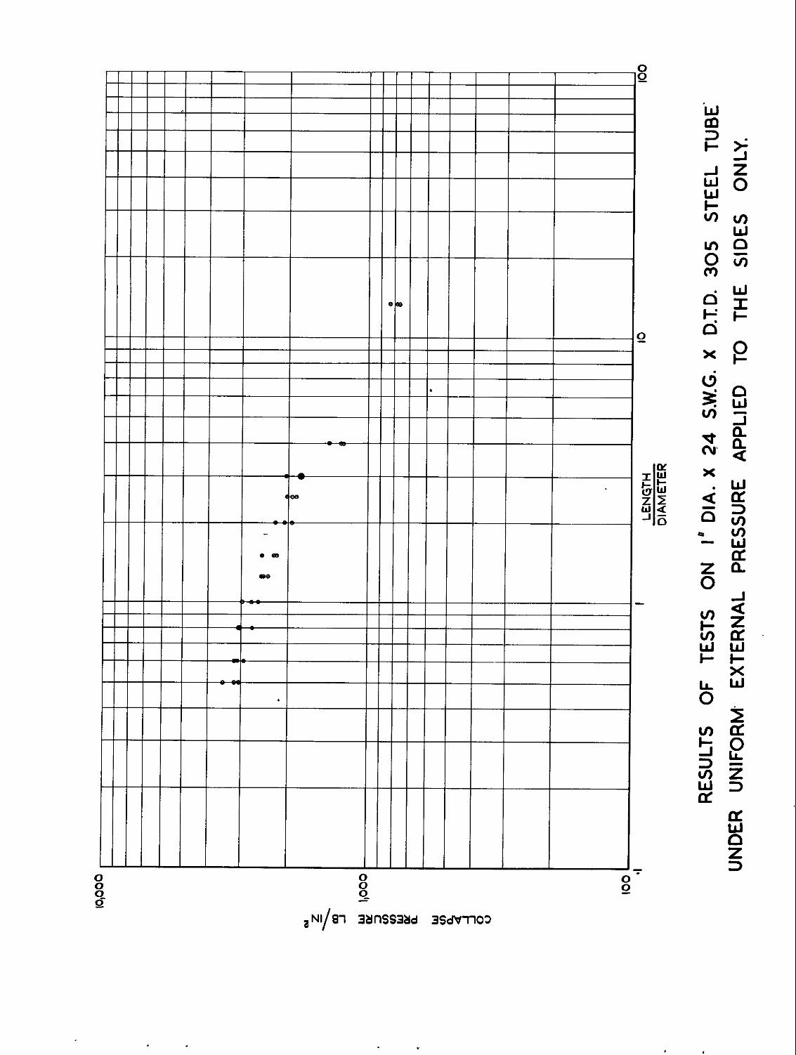

, x
h
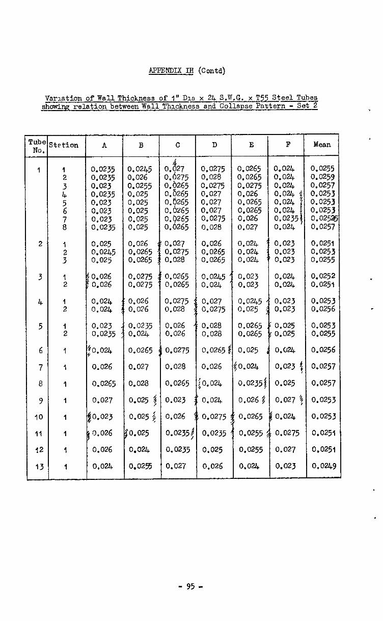
PPFENDIX IH (Contd)
Varmtion of Wall Thickness of I" Dlo x 24 S.PI.G. x T-eel Tubs showing relation between Wall Thxkness and Collapse Paxtern - Set 2
- lube NO. -
1
2
3
4
5
6
7
a
9
10
II
12
13
-
tetion
1
i
1 2
I 2
1 2
I
I
I
1
I
1
I
I
A
0.0235 0.0235 0.023 0.0235 0.023 0.023 0.023 0.0235
0.025 0.0245 0.025
0.026 0.026
0.024 0.024
0.023 0.0235
o.ouc
0.026
0.0265
0.027
0.023
0,026
0.026
0.024
B ---
:%i5 iO255 LO25 3.025 0.025 0.025 0.025
0.026 0.0265 0.0265
0.0275 0.0275
0.026 0.026
0.0235 0.0%
0.0265
0.027
0.028
0.025 :
0.025 3
0.025
0.024
0.0255
C
8 3. 27 I.6275
0.0275 0.028
Lb265 2.8265
0.0275 0.027
0.6265 3.6265
0.027 0.027
3.9265 0.0275 3.0265 0.028
0.0265 0.0265
EZ5 0:0265 0.0265 0.026 0.027
3.027 0.026 0.024 0.0275 0.0265 0.024 0.028 0.0265 0.0%
0.0265 0.0265
3.0275 0.028
0.026 0.026
0.0275
0.028
0.0265
0.023
0.026
0.0235j
0.0235
0.027
0.0245 0.024
0.027 0.0275
0.028 0.028
0.0265
0.026
0.024
0.024
0.0275
0.0235
0.025
0.026
0.023 0.023
0.0245 0.025
0.0265 0.0265
0.025
0.024
0.0235
0.026 j
0.0265
0.0255
0.0255
CL@-4
D E I?
o.ouc o.ouc 0.o.Q 0.0% $ o.ou, 0.024 f 0.0235j 0.024
0.023 0.023 0.023
0.024 0.024 0.023 0.023
0.025 0.025
0,024 0.023 4 0.025
0.027 1
o.ou, 0.0275
0.027
0.023
Mean
0.0255 0.0259 0.0257 0.0253 0.0253 0.0253 0.0252 0.0257
0.0251 0.0253 0.0255
0.0252 0.0251
E$iz .
0.0253 0.0255
0.0256
0.0257
0.0257
0.0253
0.0253
0.0251
0.0251
o.ow
- 95 -
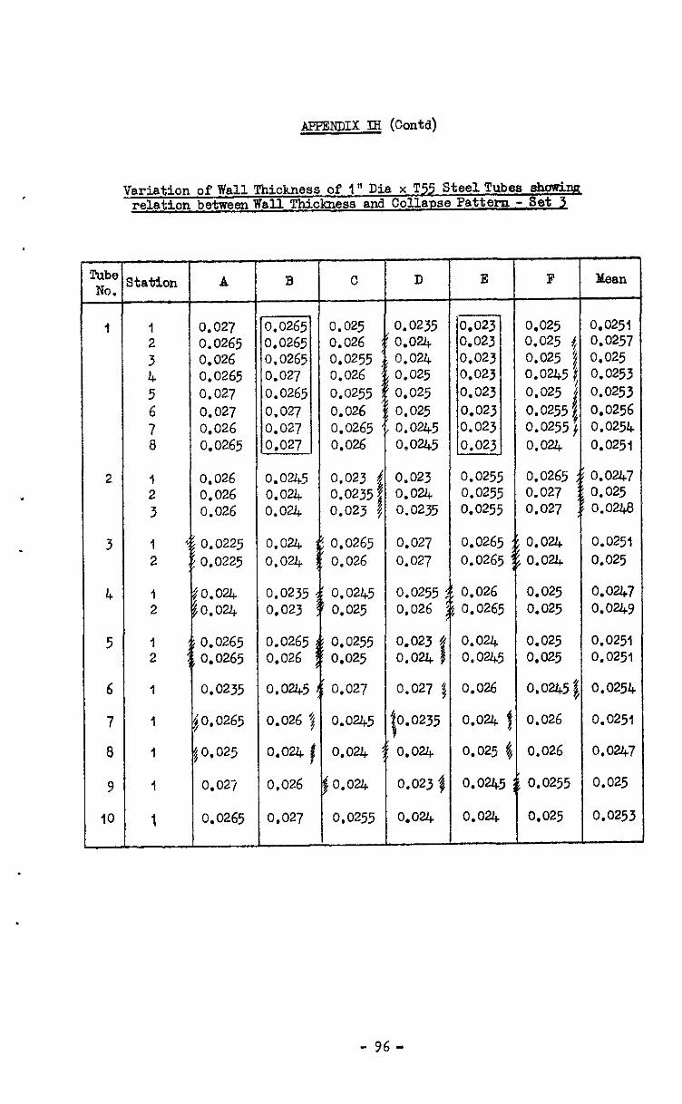
- fube NO. -
I
2
3
4
5
6
7
8
9
IO
-
AmmiDIX M (conta)
Variation of Wall Thickness of' 1" Dia x T55 SteelTubes sh0~5.w relation betweenwall Thickness and Collapse Pattern - set 3
-
S
-
tatlon A
1 0.027 2 0.0265 3 0.026 4 0.0265 5 0.027
6 0.027
7 0.026 8 0.0265
I 2 3
1 2
I 2
I 2
1
1
1
1
1
0.026 0,026 0.026
0.0225 0.0225
o.ou, 0.024
0.0265 0.0265
0.0235
.0.0265
0.025
0.027
0.0265 0.027
3.0235 0.023
0.0265 0.026
0.0245
0.026 7 0.m j 0.026
0.025 0.026 0.0255 0.026 0.0255 0.026 0.0265 0.026
0.023 i 0.0235: 0.023 i
0.0265 0.026
0.0245 0.025
0.0255 0.025
0.027
0.0245
0.024
0.0255
0.0235 o*ou, 0.024 0.025 0.025 0.025 0.0245 0.0245
0.023 o.ouc 0.0235
0.027
0.027
0.0255 0.026
0.023 4 0.024 1
0.027 1
0.0235
0.m
0.023 j
0.0-a.
F Mean
0.023 0.025 0.0251 0.023 0.025 0.0257 0.023 0.025 0.025 0.023 0.0245 0.0253 ,0.023 0.025 0.0253 0.023 0.0255 0.0256 :0.023 0.0255 0.0254 0.023 0.024 0.0251
0.025 0.025 0.025
0.0265 0.027 0.027
O.O&? 0.025 0.0248
0.026 0.026
0.026 0.026
0.024 0.w
0.026
0.024
0.025
0.024
CL@4
0.024 0.0251 o.ouc 0.025
0.025 0.0247 0.025 0.0249
0.025 0.0251 0.025 0.0251
0.0245 0.0254
0.026 0.0251
0.026 0.0247
0.0255 0.025
0.025 0.0253
- 96-
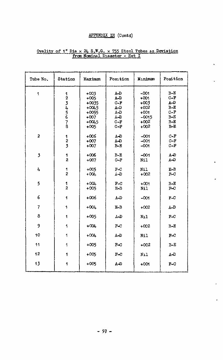
AFFmDIx IB (Corm)
C-vality ol 1" Dia x U, S.W.G. x T55 Steel Tubes as Deviation f-ran Ncminal Dmneter - Set I
Tube No.
I
2
3
4
5
6
7
a
9
IO
11
12
13
--
Station
1 3” 4
2 7 a
I
:
I 2
:
1 2
1
I
I
1
1
1
I
I
Maximum
+m3 +m5 +m35 +w5 +m55 +007 +w5 +m5
+006 +m7 +m7
+CC6 +m7
+m5 +004
+004 +@J5
+OiJ6
+m4
+@J5
+004
+W
+@J5
+w
+W
Posltlon
;I; C-F A-D A-D A-D C-F C-F
A-D A-D B-E
3-E C-F
F-C A-D
F-C E-B
A-D
E-B
A-D
F-C
A-D
F-c
F-C
A-D
Mlninnrm
-001 +CO1 +OOJ +002 too1 -0015 too2 too2
-001 -001 -001
-001 Nil
Nil +KJ2
too1 Nil
-001
too2
NJ.1
too2
Nil
+002
Nil
tool
Position
B-E C-F A-D B-E C-F B-E B-E B-E
C-F C-F C-F
A-D A-D
E-B F-C
B-E F-c
F-C
A-D
F-C
B-E
F-C
3-E
A-D
F-C
- 47 -

APPENDIX IH (Contd)
Ovallty of 1" Dla x 2.4 S.W.G. x T55 Steel Tubas as Deviatxon fkom Nominal Diameter - Set 2
Tube No.
1
2
3
4
5
6
7
8
9
IO
11
12
13
Station
I J” 4 2 7 8
lJ 3
I 2
1 2
1 2
I
1
1
1
I
1
I
1
Ida-
+003 +005 to035 too45 +0055 too7 coo45 +005
too6 too7 too7
to06 too7
+ 005 +0@4
+004 +005
+006
+oaq
too5
too4
too4
coo5
too5
too5
Position Minimum Position
A-D A-D
:I:
:I; C-F C-F
-001 B-E too1 C-F +a3 A-D too2 B-E to01 C-F -0015 B-E too2 B-E too2 B-E
A-D -001 C-F A-D -001 C-F B-E -001 C-F
B-E -001 A-D F-C Nil A-D
F-C Nil E-B A-D +002 F-C
F-C eOO1 B-E E-B Nil F-C
A-D -001 F-C
B-E +002 A-D
A-D Nil F-C
F-C coo2 B-E
A-D Nil F-C
F-C +002 B-E
F-o Nil A-D
A-D too1 F-C
- YB-
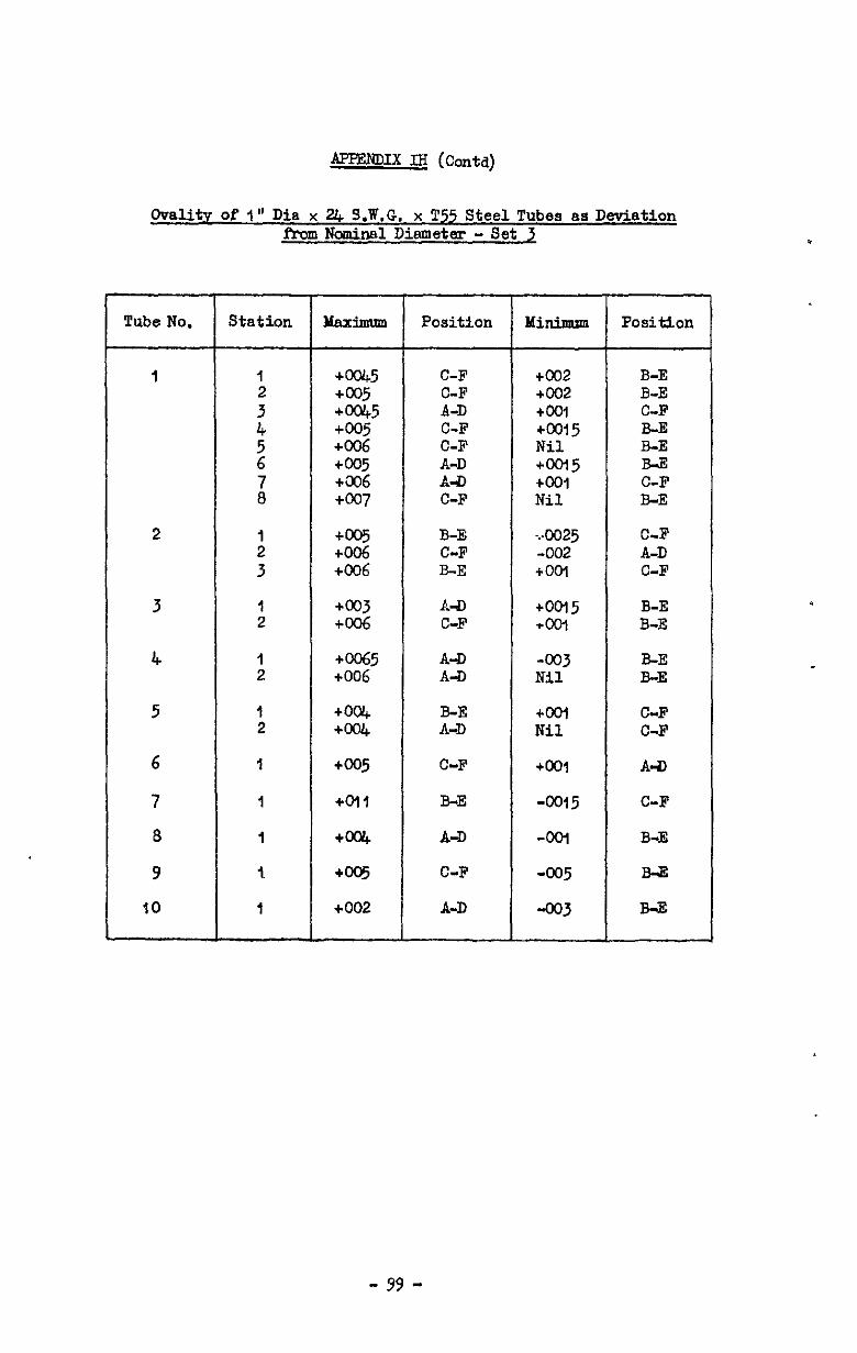
APPEmIX IH (coda)
Ovality of I" Dia x Z& S.W.G. x T55 Steel Tubes ss Deviation fbm Nominal Dismetex - Set 3
Tube No.
I
2
3
4
5
6
7 8 9
IO
Station Maximum
+fx&5 +m5 +0045 +m5 +006 +005 +a06 +cQ7
+005 +006 +C06
+m3 +006 +m5 +006
+w +W +005
+Dli +004 +005 +002
Position Minimum
C-F C-F A-D C-F C-F
E C-F
+002 B-E +cO2 B-E +00-l C-F +cO15 B-E Nil B-E +m5 B-E too1 C-F Nil B-E
B-E C-F B-E
-..0025 C-F -002 A-D tool C-F
A-D tool5 C-F +W
A-D -003 A-D Nil
B-E tan A-D Nil
C-F too1
B-E -0015
A-D -WI
C-F -005
A-D -003
Position
B-E B-E
E-E B-E
C-F C-F
A-D
C-F
B-E
B-3
B43
- 99 -
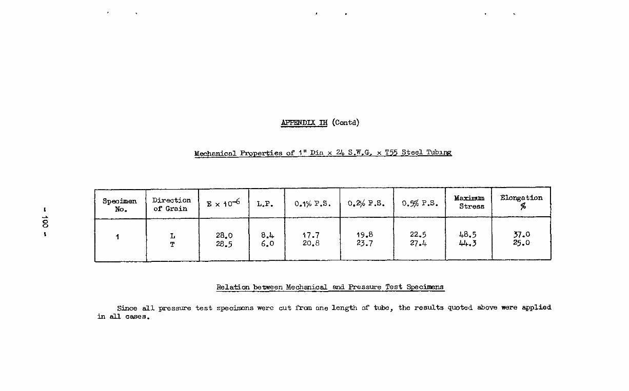
APPE!ZJDIX M (Contd)
&&&cd Properties of I” Di:t x U, S.W.G. x T55 Steel Tubmp;
I
8
Speoimen Direction No. of Grain
Ex104 L.P.
, I L 28.0 8.4 T 28.5 6.0
0.5$ P.S.
22.5 27.4
IdaxiJmml Elongation Stress %
RelatianbemeenMeohtioal and Pressure Test Specbms
Since all pressure test speciraens were cut from one length of tube, the results quoted above were applied in all cases.
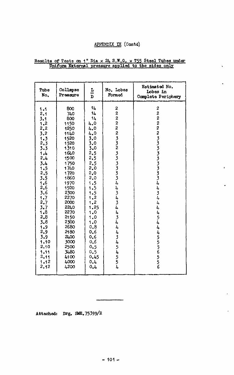
APPENDLX IH (conta)
Results of Tests on 1" Dia x U, S.W.G. x T55 Steel Tubes under Upifom External pressure applied to the sides only
Tubs collspse L No. Lobes Estimated No.
No. Pressure 5 Rumed Lobes in
Ccmplete Periphery
I .I 2.1 3.1
;*“z 3:2 1.3
::: 1.4 2.4
:*; .
;I; .
;:: 1.7
:*: 118
;:i
a:; 3.9 1.10 2.10 1.11 2.11 1.12 2.12
8oc 740 800
1150 1250 114.0 1520 1520 1310 1640 1500 1750 1740 1720 1860 1970 1920 2300 2270 mlo
hF$ 2150 2joo 2680 2180
E 2500
2s
;zi
14 14 14
::: 4.0
:?I
23:; 2.5 2.5
2,” 210 1.5 1.5 1.5 1.2 1.2 1.25 1.0 1.0 1.0 0.8 0.6 0.6 0.6 0.5
:::5 0.4 0.4
2 2 2 2 2
: 3 2
:
;
:
:
:
z 4
t 4
; 4
2
: 4
Attached: Dr& S&75399/R
- 101 -
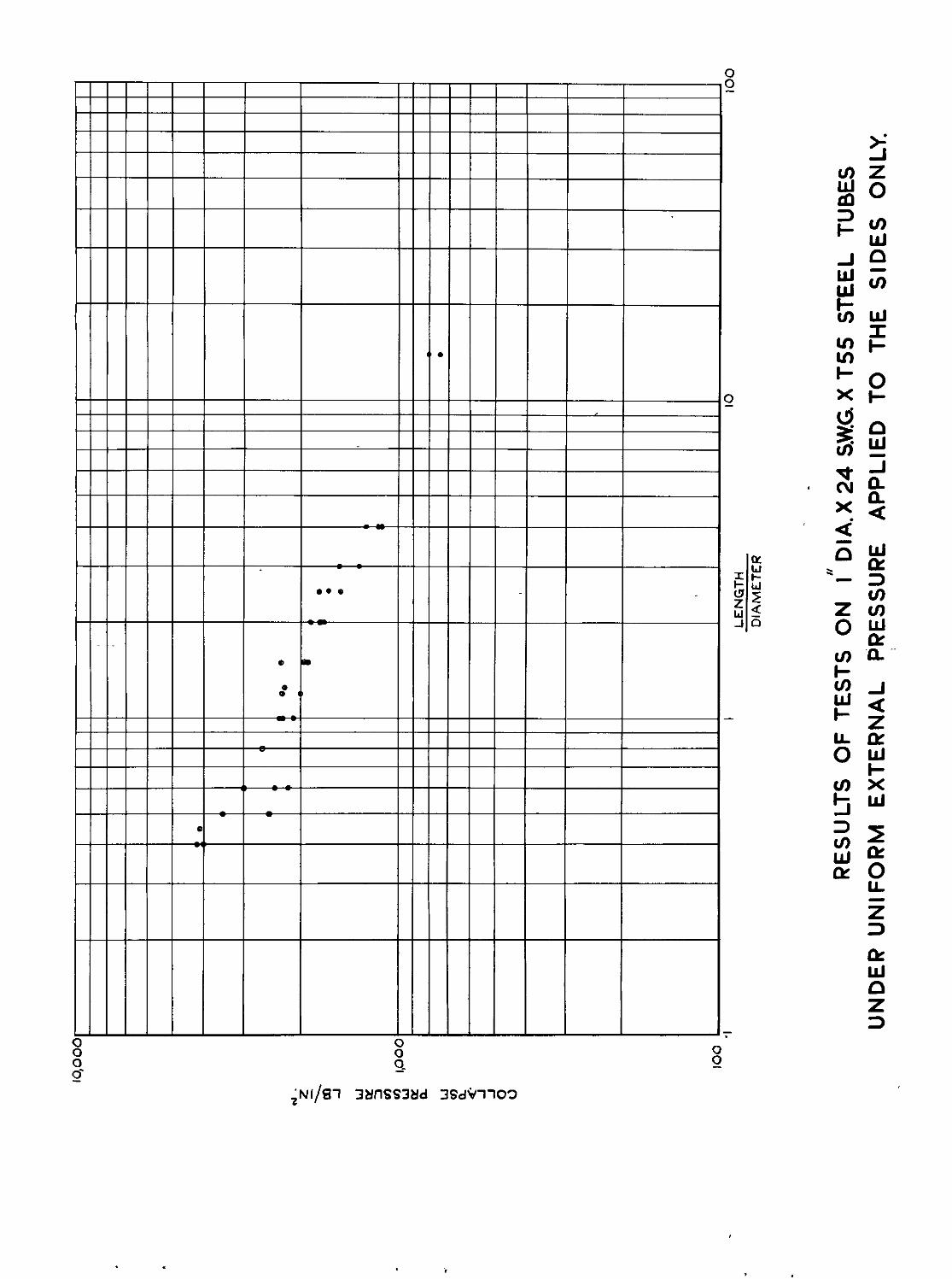
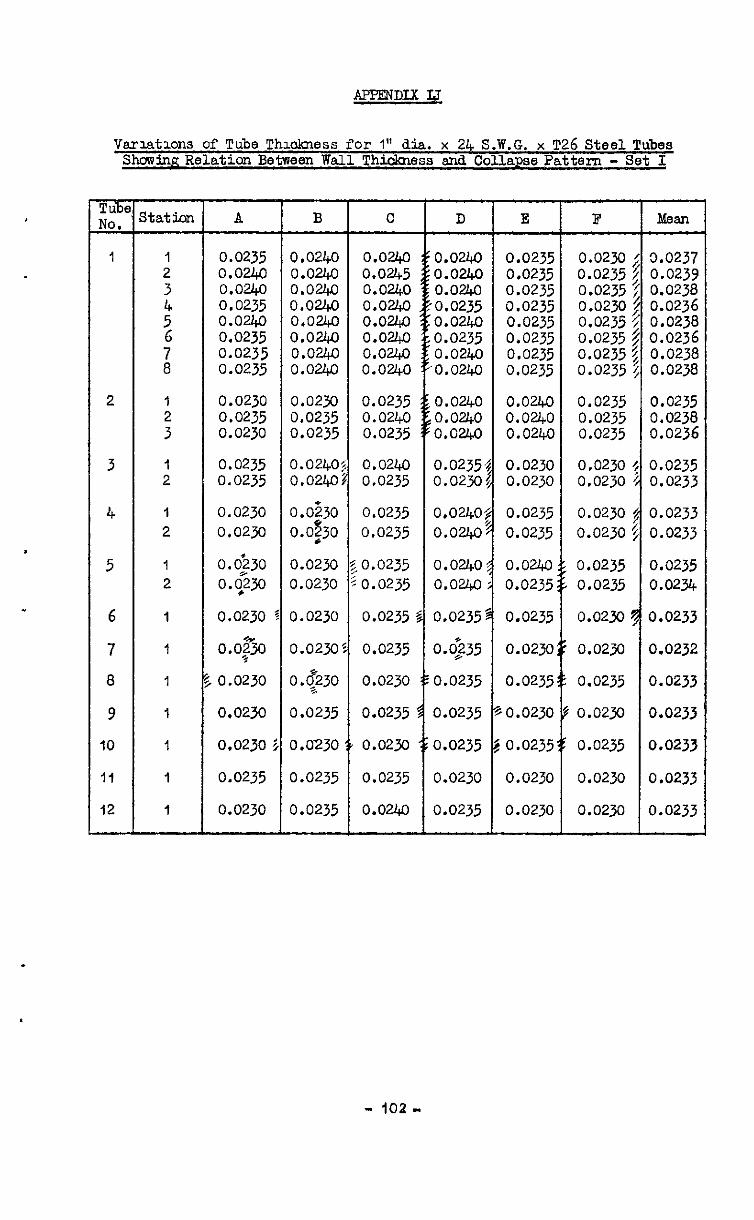
APPENDIXIJ
Varlatlons of Tube Thmkmss for 1 ' dia. x 24 S.W.G. x T26 Steel Tubes ShowinaRelation Between Wall Thickness and Collapse Pattern - Set I
m No.
1
2
3
4
5
6
7
a
9
IO
11
12 -
Itat5nn
1 2
'4 5 6
i
: 3
1 2
1 2
1 2
1
1
1
1
1
1
1
A
0.0235 0.0240 0.024n 0.0240 0.0235 0.0230 0.0240 0.0240 0.0245 0.0240 0.0235 0.0235 0.0240 0.0240 0.0240 0.0240 0.0235 0.0235 0.0235 0.0240 0.02lQ 0.0235 0.0235 0.023o 0.0240 0.0240 0.0240 0.0240 0.0235 0.0235 0.0235 0.0240 0.0240 0.0235 0.0235 0.0235 0.0235 0.0240 0.0240 0.024Ll 0.0235 0.0235 0.0235 0.0243 0.0240 0.0240 0.0235 0.0235
0.0230 0.023o 0.0235 0.0235 0.0230 0.0235
0.0235 0.0235
0.0230 0.0230
0.0230 o.po
0.0230
0 * o,po
0.0230
0.0240 0.0240
o.os.30 0.0?30
0.0230 0.0230
0.0230
0.0230
0.$230
0.0235
0.0230
0.0235
0.0235
0.0235 0.0240 0.0235
0.0240 0.0235
0.0235 0.0235
0.0235 0.0235
0.0235 :
0.0235
0.0230
0.0235
0.0230
0.0240 0.0240 0.0240
0.0235. 0.0230
0.0230
0.0230
0.0235
0.0230
0.0240 0.0240 0.0240
0.0230 0.0230
0.0235 0.0235
0.0240 0.0235
0.0235
0.0230
0.0235
,0.0230
0.0235
0.0235 0.0235 0.0235
0.0230 0.0230
0.0230 0.0230
0.0235 0.0235
0.023o
0.0250
0.0235
0.023a
0.0235
0.0235
0.0240
0.0240: 0.024.0~
0.0240 0.0240
0.0235'
o.@35
0.0235
0.0235
0.0235
0.0230
0.0235
0.0230
0.0230
0.0230
0.023cl
B c D E B Mean
3.0237
:*o":;: 0:0236 0.0238 0.0236 0.0238 0.023a
0.0235 0.0238 0.0236
0.0235 0.0233
0.0233 0.0233
0.0235 0.0234
0.0233
0.0232
0.0233
0.0233
0.0233
0.0233
0.0233
- 102 -
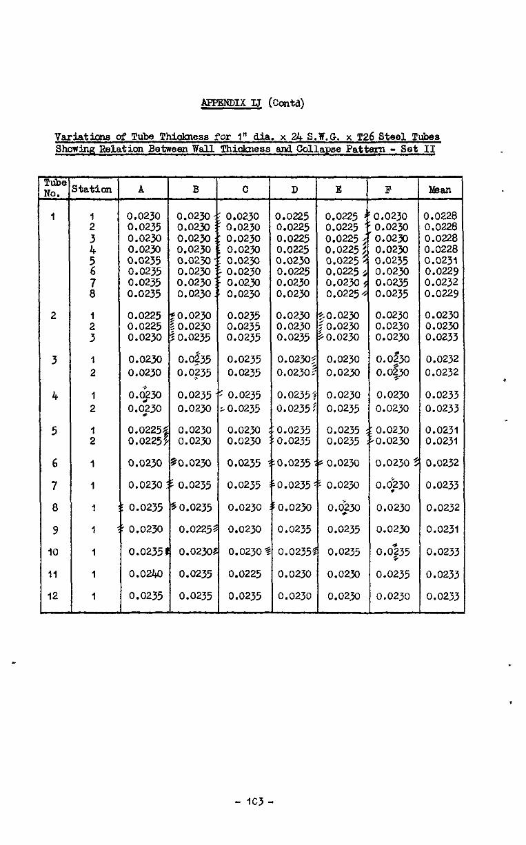
AFfmDIx IJ (CotAl)
vaci&icpls of Tube Thiokness for 1" dia. x 24 S.W.G. x ~26 Steel Tubes Showing Relation Between Wall Thidamss and Collapse Pattern - Set II
2
3
4
5
6
7
8
9
10
II
12 -
tation
: ;t 5
G 8
1
;
1
2
I
2
:
I
I
I
I
I
1
I
A B
0.0230 0.0230 0.0235 0.0230 0.0230 0.0230 0.0230 0.0230 0.0235 0.0230 0.0235 0.0230 0.0235 0.0230 0.0235 0.0230
0.0225 :o.owJ 0.0225 ~0.0230 0.0230 ZO.0235
0.0230 0.0$35 0.0230 0.0:35
o.go 0.0235 0.0;30 0.0230
0.0225$ 0.0230 0.0225~ 0.0230
0.0230 %o.ozy~
0.0230:s 0.0235
0.0235 50.0235
0.0230 0.0225
0.0235t 0.023C
0.0240 0.0235
0.0235 0.0235
C
0.0230 0.0230 0.0230 0.0230 0.0230 0.0230 0.0230 0.0230
0.0235 0.0235 0.0235
0.0235 0.0235
0.0235 ,0.0235
0.0230 0.0230
0.0235
0.0235
0.0230
0.0230
0.0230
0.0225
0.0235
D E
0.0225 0.0225 0.0225 0.0225 0.0225 0.0225 0.0225 0.0225 0.0230 0.0225 0.0225 0.0225 0.0230 0.02x) 0.0230 0.0225
0.0230 TO.0230 0.0230 : 0.0230 0.0235 $0.0230
0.0230$ 0.0230 0.0230? 0.0230
0.02352 0.0230 0.0235 5 0.0235
0.0235 0.0235 0.0235 0.0235
,0.0235 is 0.0230
,0.0235 5: 0.0230
0.023cl o.<22jo
0.0235 0.0235
0.02358 0.0235
0.0230 0.0230
0.0230 0.0230
F Maen
0.0230 3.0228 0.0230 0.0228 0.0230 0.0228 0.02jo 0.0228 0.0235 0.023t 0.0230 0.0229 0.0235 0.0232 0.0235 0.0229
0.0230 0.0230 0.0230
o.of30 o.o$o
0.0230 0.0230
0.0230 0.0230 0.0233
0.0232 0.0232
0.0230 0.0230
0.0230
0.~230
0.0230
0.0230
0.0235
0.0235
0.0230
0.0233 0.0233
0.0231 0.0231
0.0232
0.0233
0.0232
0.0231
0.0233
0.0233
0.0233
- ICJ-
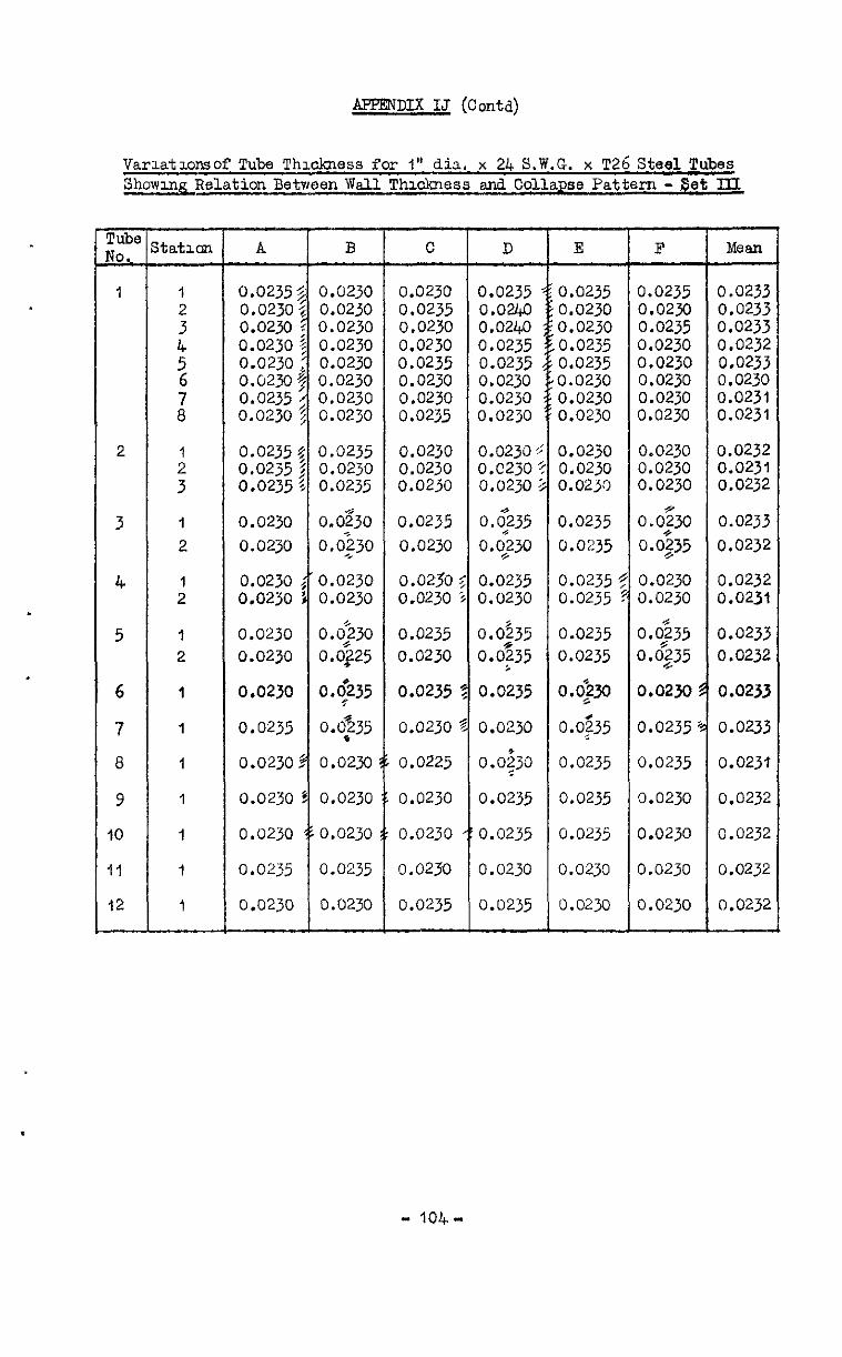
AFFENDIX IJ (Contd)
Varlatlonsof Tube Thmkness for 1" dia, x 24 S.W.G. x T26 Steel Tubes Showmg Relation Between Wall Thxkness md Collapse Pattern -Set III
tiq r&&,
1
2
3
4
5
6
7
8
9
10
11
12
ltatlon
1
;
1
2
1 2
1
2
I
I
1
1
1
1
1
A
0.0235 0.0230 0.0230 0.0230 0.0230 0.0230 0.0235 0.0230
0.0235 0.0235 0.0235
0.0230
0.02~0
0.0230 0.0230
0.0230
0.0230
0.0230
0.0235
0.0230
0.0230
0.0230
0.0235
0.0230
B
0.0230 0.0230 0.0230 0.0230 0.0230 0.0230 0.0230 0.0230
0.0235 0.0230 0.0235
O"OS30
0.0230
0.0230 0.0230
0.0230 0.0325
$235
0.0235
0.0230
0.0230
0.0230
0.0235
0.0230
0.0230 0.0235 0.0230 0.0230 0.0235 0.0230 0.0230 0.0235
0.0230 0.0230 0.0230
0.0235
0.0230
0.0230 0.0230
0.0235
0.0230
0.0235
0.0230
0.0225
0.0230
0.0230
0.0230
0.0235
0.0235 0.0240 0.0240 0.0235 0.0235 0.0230 0.0230 0.0230
0.0230: 0.~230. 0.0230:
OS<235
0.0230
0.0235 0.0230
0.0535
0.0!35
0.0235
0.0230
0.0$30
0.0235
0.0235
0.0230
0.0235
E
0.0235 0.0230 0.0230 0.0235 0.0235 0.0230 0.0230 0.0230
0.0230 0.0230 0.0230
0.0235
0.0235
0.0235: 0.0235
0.0235
0.0235
o.ogtl
0.0235
0.0235
0.0235
0.0235
0.0230
0.0230
0.0235 0.0230 0.0235 0.0230 0.0230 0.0230 0.0230 0.0230
0.0230 0.0230 0.0230
o.o& 0.0235
0.0230 0.0230
0.0235
0.0235
0.0230
0.0235
0.0235
0.0230
0.0230
0.0230
0.0230
0.0233 0.0233 0.0233 0.0232 0.0233 0.0230 0.0231 0.0231
0.0232 0.0231 0.0232
0.0233
0.0232
0.0232 0.0231
0.023:
0.0232
0.0233
0.023:
0.0231
0.0232
0.0232
0.0232
0.0232
- 104-
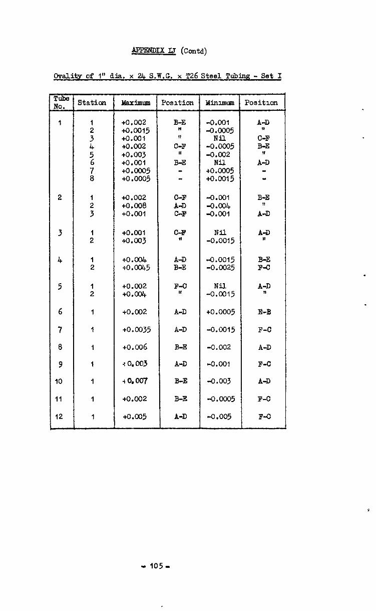
AFPENDIx IJ (coda)
Ovelity of 1” dia. x 24 S.W.G. x T26 Steel Tubing - Set I
C-F +0.002 O-F -0%05 B-E +0.003 ,I -0.002 ,I
+0.001 B-E Nil A-D +o.oco5 - +o.G005 - +o .0005 - to.0015 -
2 I
:
+0.002 O-F -0.001 B-E t0.008 A-D -0.004 ,I +O.ool C-F -0.001 A-D
3 :
+O.ool C-F Nil A-D to.003 " -0.0015 In
4
5
6
7
a
9
IO
ii
12
:
:
1
I
1
I
1
I
1
to.ax io.cat5
+0.002 to.004
to.002
to.0035
+0.006
20.003
t0.007
+0.002
to.005
A-D B-E
F-O I,
A-D
A-D
B-E
A-D
B-E
B-E
A-D
"0.0015 -0.0025
-0%15
+0.0005
-0.cm5
-0.002
-0.001
-0.003
-0.ooo5
-0.005
B-E F4
A-D 11
E-B
F-C
A-D
F-C
A-D
F-O
F-O
.
-105-
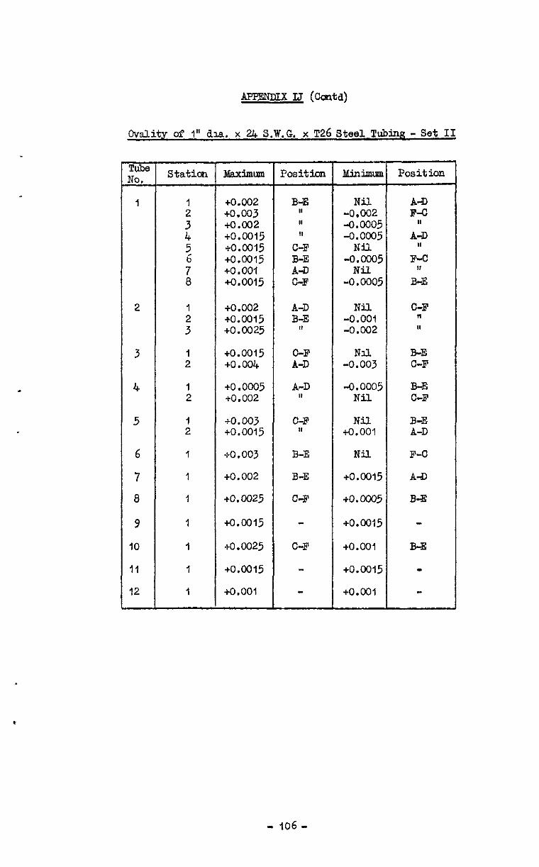
lLFTmmx IJ (Corm)
Cvality of I" ha. x UC S.W.G. x T26 Steel Ipubin~? - Set II
pubs $&
I
2
3
4
5
6
7
8
9
IO
11
12
-
Station
1
$ 5, i 1
:
I 2
1 2
:
1
1
1
I
I
i
1
ldaximunl
+0.002 +o.c03 a.002 +0.0015 +0.0015 +0.0015 io ,001 +0.0015
+o.c02 e0.0015 +0.0025
+0.0015 +0.004
+0.0005 +0.002
+0.003 +0.0015
eo.003
+0.002
+O.W25
+0.0015
to.0025
+o.cm5
4-0.001
Positioll
B-E II ,I II
C-F B-E A-D C-F
A-D B-E
II
C-F A-D
A-D #I
C-F I,
B-E
B-E
C-F
C-F
MinimlBn
Nil -0,002 -0.cOo5 -0.0005
Nil -0.0005
Nil -0.0005
Nil -0.001 -0.002
Nil. -0.003
-0.ocm5 Nil
Nil +O.OOl
Nil
+o.c015
+o.K05
+0.0015
+0.001
+0.0015
+0.001
Position
A-D F-C
II A-D
II F-C
9, B-E
C-F " I,
B-E C-F
B-E C-F
B-E A-D
F-C
A-D
B-E
B-E
w
- 106 -
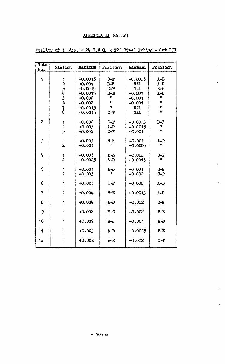
APPENDIX LJ (Contd)
OvaJzityofl~dia x24 . S.W.G. x T26 Steel Tubing - Set III
Pube JO. Station Maximm Position Minimm Position
I I +0.0015 C-F -0.0005 A-D
: io.oo1 B-E Nil A-D +0.0015 C-F Nii
4 +0.0015 B-E -o.cm Z 5 +0.002 I8 -0.001 "
i
+O.O02 al -0.001 fl +0.0015 n Nil ,I
+0.0015 C-F Nil $9
2 I +0.002 C-F -0.ooO5 B-E : +0.003 A-D -0.0015 fl
+o.c02 C-F -0.001 t!
3 : +0.003 B-E -0.001 A-D +0.001 II -0.m5 )t
4 1 G-0. 003 B-33 -0.002 C-F 2 +0.0025 A-D -0.0015 I’
5 1 +o.cm A-D -0.001 B-E 2 +o.c03 11 -0.002 C-F
6 1 to.003 C-F -0.002 A-D
7 I +0.004 B-E -0.0015 A-D
8 1 +0.004 A-D -0.002 CFi?
9 1 +0.002 F-c -0.002 B-E
IO 1 +0.002 B-E -0.001 A-D
II 1 +0.003 A-D -0.0025 B-E
12 I +0.002 B-E -0.002 C-F
- 107-

- 108 -
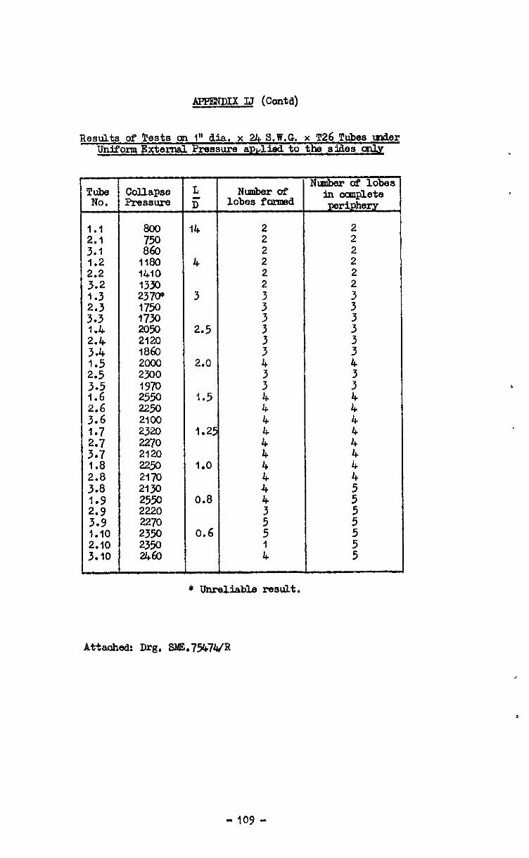
APPENDIX IJ (Contd)
Results of 'Pests on 1" dia. x 24 S.W.G. x ~26 Tubes under UnifonnExternal Pressum apdid to the sides oily
2.2 3.2
::: 3.3
::“, :-; 215
3 ::2 ::: 3.7 1.8 2.8 3.a
::; 3.9 1.10 2.10 3.10
Nmber of Tube Collapse L Nmber of No. Pressure D' lobes Pormld
.inocmlpY periphr,,
1:: 3.1 1.2
14
4 1410 1330 237F 1750 1730 m.w 2120 1863
ZEi 1970 2550 =50 2100 2320 2270 2120 2eQ 2170 2130 2550 2220 2270
3
2.5
2.0
1.5
1.25
1.0
0.8
23% 0.6 2350 2460
I I I I
* Unreliable rfc3d.t.
Attaohed: Dr& SME.75b7447
- 109 -
.
Variation of tube thickness of I” dia. x 21 sw~ x DlTl 102A Steel tube showing relation between wall thioknsss and
collamc pattern. SET I
Tube NO. -
I
2
3
4
5
6
7
6
9
10
II
12 -
StatiOn
1
:
!
i
1 2 3
1 2
I 2
1 2
1
1
I
1
1
1
1
A
0.0235 0.0230 0.0230 0.0230 0.030 0.0230 0.0225 0.0225
0.0235 0.0235 0.0235
0.0225 0.0220
0.024.0 0.0235
0.0230 0.0230 i 0.0230
0.0230
0.09 O.o225$
0.02;5
0.0250
0.0250
1
fi /
,
I
I
,
D
0.~250 0.0250 o.ow 0.024.0 oa45 0.0240 0.023.0 0.0240
0.0225 0.0230 o.P235
0.0240 0.0240 J
0.0230 0.02x)
0.0240 oa45
o.op
0.0235
0.023Oj
0.0250
0.0245
0.0225
0.0225
- 110..

1
AFPENDn IK (Corm)
Variationuftubethidcness of 1" dia. x 2l+ SWJZ xmDiOZ4 Steel tube showin relation bstwsen wall tbickzss ard
mllanae pattern. SF2 II
pube Station No.
1 I
: 4 5 6
;
2 1
;
3 I 2
4 I 2
5 1 2
6 1
7 I 1 a 1
9 I
IO 1 L II 1
12 1
IA IB Ic ID I E I I
F Mean
0.0250 0.0240# 0.0225 Q.0255 0.0240/ 0.0210 0.0250 0.02404 0.0245 0.02404
0.0210 0.02x)
0.0250 0.0240 0.0250 0.0240
o.oi20 0.0220
0.0225 0.0235
0.095 0.0225 0.0235 0.0225 0.0240
0.0230 0.0225 0.0220
0.0220 0.0235 0.0225 0.0240
0.0240 0.0250 0.0245 0.0250
0.0230 0.045 0.0250 0.0240 0.0230 0,02j+5 0.0250 0.0240
0.0245 0.0250 0.0245 o.ouJ 0.0240 0.0235 0.0245 0.0245
0.0230 0.0250 0.0245 0.0240
0.0245 0.0250 0.0230 o.o+
0.0240 0.0235~~0.0230 0.0235
0.023Of 0.0230 0.0250 0.0&O
0.0245 0.0250 0.0235 0.0230
0.0220 0.022Oj 0.0220 0.0233
0.0220 f 0.0225 0.0233 0.0230 0.0233
0.0215/ 0.02151 0.0215 c
0.0225 0.0225 0.0231 0.0232 0.0225 0.0232
0.0215' O.OZ'O 1
0.0220 0.0231 0.0220 0.0234
0.0240 0.0240 0.0232 0.0245 0.0240 0.0232 0.0245 0.0245 0.0232
0.0230 0,0232 0.0230 0.0235
0.0225 0.0236 0.0225 0.0238
0.0220 0.02,o > 0.0236 0.0230 0.0 d 0 0.0238
0.0235 0.0250f 0.0235
0.0240 0.0238
0.0225 0.0237
0.0240 0.0237
0.0235 0.0250 0.0238
0.0235 0.0230 0.0236
0.0235 0.0235 0.0238
- 111 -
APPENDIX IK (Corei)
Variation of wall thidcnase of I" dia. X 24 ma X DTD IOW Steel tub3 showing relation between wall thickness and
collage pattern. SF3 III
izk Station A B c D E F Mean
I 1 0.0240 0.0240 0.0250 0.0250 o.o.i50 0.0240 0.0245 0.0235 0.0240 0.0245 0.0250 0.0&O 0.0235 0.0241 0.0235 0.0240 0.0245 0.0250 0.0240 0.0235 0.0241 0.0235 0.0240 0.0235 0.0245 0.0<40 0.0240 0.0239 0.0230 0.0235 0.0245 0.0245 0.0.&O 0.0235 0.0238 0.0230 0.0235 0.0245 0.0240 0.0240
Od40 0.0235 0.0238
0.0235 O.OZl+O 0.0230 .0,0240 0.0235 0.0238 0.0240 0.0240 0.0230 0.0245 0.0$40 0.0235 0.0238
0.0235 0.0242
APPENDIX IB (coda)
0valit.v of 1" Dia x . sw x DTD 102A Stesl tubes at deviation fromN&~ Diameter - SRI! I
3 7 2
4 1 2
5 1 2
6 1
7 I
Maximum
+0.003 +0.003 t0.c06 +0.007 +om35 +o.c03 +0.002 to.0015
Position
B-E n
c 4' 11
A-D I?
B-E C-F
C-F II I,
A-D II
B-E C-F
B-E C-F
A-D
A-D
B-E
A-D
k-D
C-F
C-F
MinimuP Position
-0.001 A-D -0.002 C-F -0.003 A-D -0.CO5 A-D
Nil C-F Nil C-F
+0.0005 C-F -0.001 A-D
-0.0015 B-E -0.0005 A-D -0.002 B-E
-0.002 B-E -0.003 tt
Nil C-F -0.004 A-D
Nil A-D +o.ool "
-0.0045 B-E
-0.005 B-E
-0.003 A-D
-0.002 C-F
-O.Kll B-E
-0.0015 A-D
4.002 B-E
- 113-
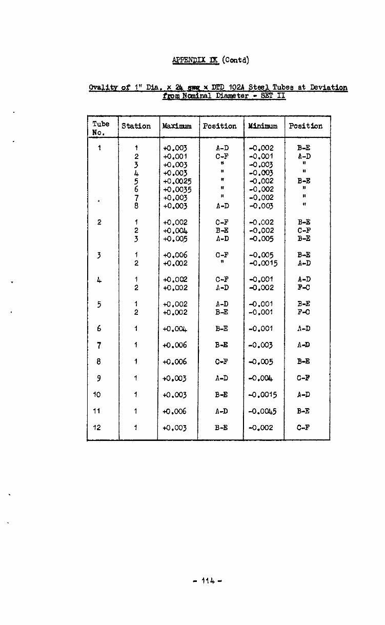
Ovalitv of 1" Dia. x 2h mst x Dl'D 102A Steel Tubes at DevLation f~mNdna1 Diameter -SET II
Tube No.
2 1 to.002 C-F : ~.W B-E
tO.005 A-D
3 1 4.006 C-F 2 +0.002 11
4 1 tO.002 C-F 2 +0.002 A-D
5 1 +0.002 A-D 2 to.002 B-E
6 1 +O.W B-E
7 1 t0.006 B-E
8 I t0.006 C-F
9 1 +o.c03 A-D
IO 1 +O.c03 B-E
II 1 t0.006 A-D
12 I +0.003 B-E
Minimum Position
-0.002 B-E -0.001 A-D -0.003 tl -0.003 In 4.002 B-E -0.002 IN -0.002 In -0.003 Ia
-0.002 B-E -0.002 C-F -0.005 B-E
-0.005 B-E -0.0015 A-D
-0.001 -0.002 iz
-0.001 B-E -0 .OOl F-C
-0.001 A-D
-0.003 A-D
-0.005 B-E
-0.004 C-F
-0.0015 A-D
-0.0045 B-E
-0.002 C-F
-114-
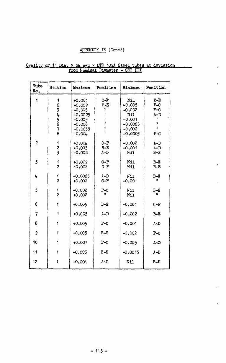
&'PERDIX IK (Contd)
Ovallty of 1" Dia. x 24 WR x DTD 102A Steel tubes at deviation fromNknal Diameter - SET III
EG- TO.
1
2
3
4
5
6
7
8
9
IO
I1
12
station
1
: 4
2
s7
1
:
I 2
1 2
1 2
1
1
1
1
1
1
1
Maximum
iO.003 +0.009 +0.005 tO.0025 +0.005 +0.006 +0.0055 +o a004
+0.004 tO.003 +0.002
+0.002 to.002
~0.0025 to.cQ2
+0.002 +o.cQ2
to .005
+0.005
+0.005
to ,005
+0.007
Co.006
to ,004
Poeitlon
C-F B-E
,I ,I ,I 11 1, I,
C-F B-E A-D
C-F C-F
A-D C-F
F-C 1,
B-E
A-D
F-O
E-E
F-C
B-E
A-D
:
I
Minimum
Nil LO.005 -0.002
Nil -0.001 -0.0025 -0.cQ2 -0.0005
-0.002 -0.001
Nil
Nil Nil
Nil -0.001
Nil Nil
-0.001
-0.002
-0.001
-0.002
-0.005
-0.0015
Nil
Posit ion
B-E F-C F-C A-D
II II 11
F-C
A-D A-D B-E
B-E B-43
B-E 1,
B-E 1,
C-F
B-E
A-D
F-c
A-II
A-D
B-E
- i15-
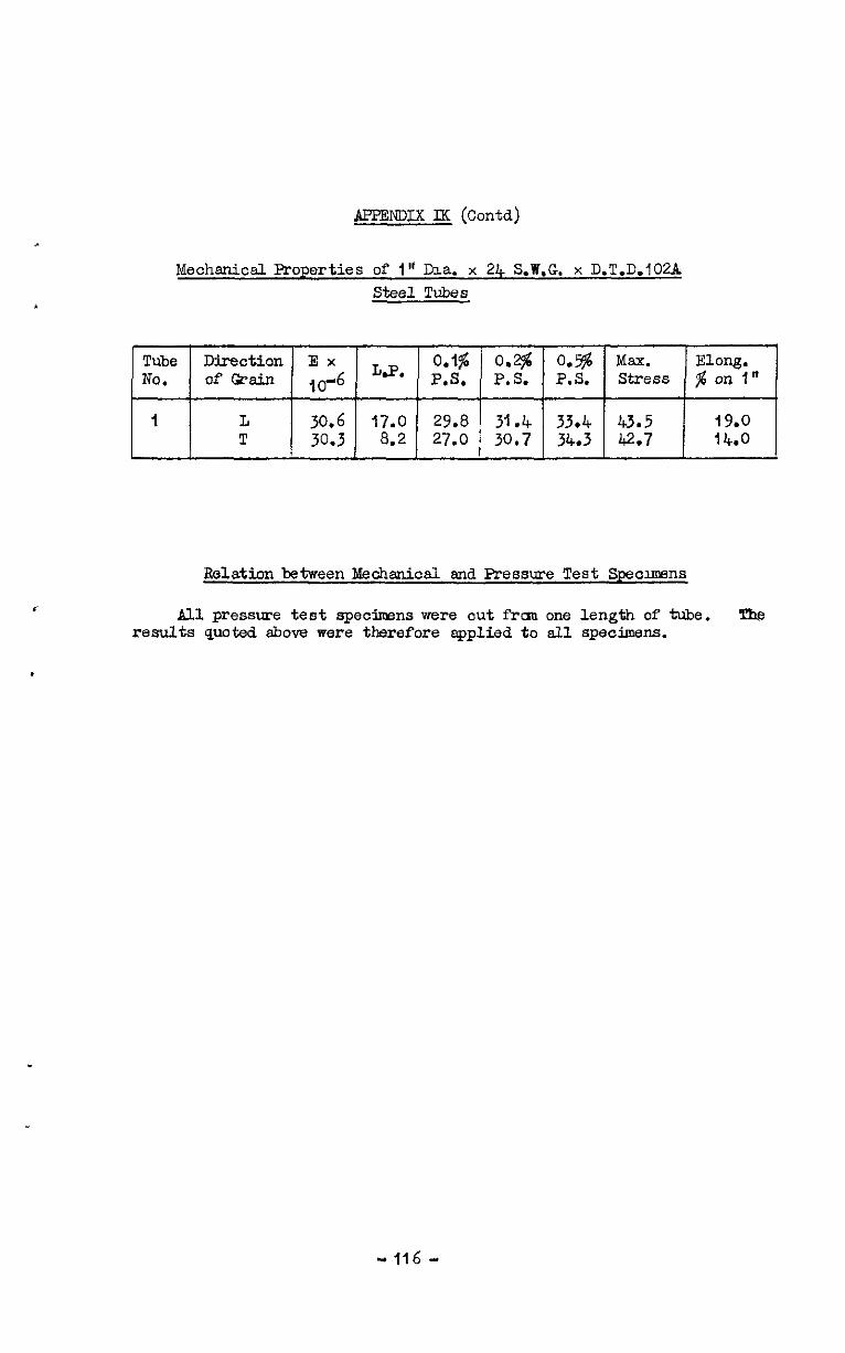
APFmDIx M (Contd)
Edechaniml Properties of 1" Dia. x 24 S.W.G. x D.T.D.102A Steel Tubes
Tube Direction E x LQ*
0.1% 0.2$ o.!g Max. ElOXlg. NO. of Grain ,o-6 PS ,. PS . . PS . . stress $ on i"
I L 30.6 17.0 29.8 31.4 33.4 43.5 19.0 T 30.3 8.2 27.0 30.7 34.3 42.7 14.0
Relation between Mechanical and Pressure Test Speolrnena
All pressure test specimens were cut fran one length of tie. The results quoted above were tk-efore applied to all specimens.
.
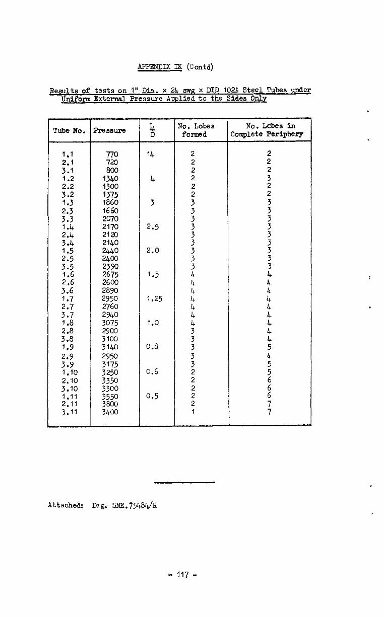
APPENDIX IX (Con@
Results of tests on 1" Dia. x 2.4 SWR x DTD 102A Steel Tubes under Unifor External Pressure Amliedto the Sides Only
Tube No. Prsssure L No. Lobes No. Lcbea in D formed Complete Periphery
1.1 $E 800
14 2 2 ::: 2 2 2
1.2 1340 4 2
::; 1375 1300 2 i 2
1.3 1860 3 : ::: 2070 ?660 3 :
2: 2170 2120 2.5 : :
3.4 2140 : :
2: g
2.0 : 3 3 3.5 i 3 1.6 2675 1.5 2.6 2600 4"
3.6 2890 k ::: 2950 2760 1.25 4 i
3.7 2940 :: : 1.8 3075 1.0
::: ;zz 2 :: 4 1.9 3140 0.8 : 2’9 2950 3175 3 3 :
1 .lO 3250 0.6 2 : 2.10 3350 2 3.10 3300 1.11
: t
3358z 0.5 6
2.11 2 3.11 3400 1 :
Attached: Drg. SMFL?54&/FI
- 117 -

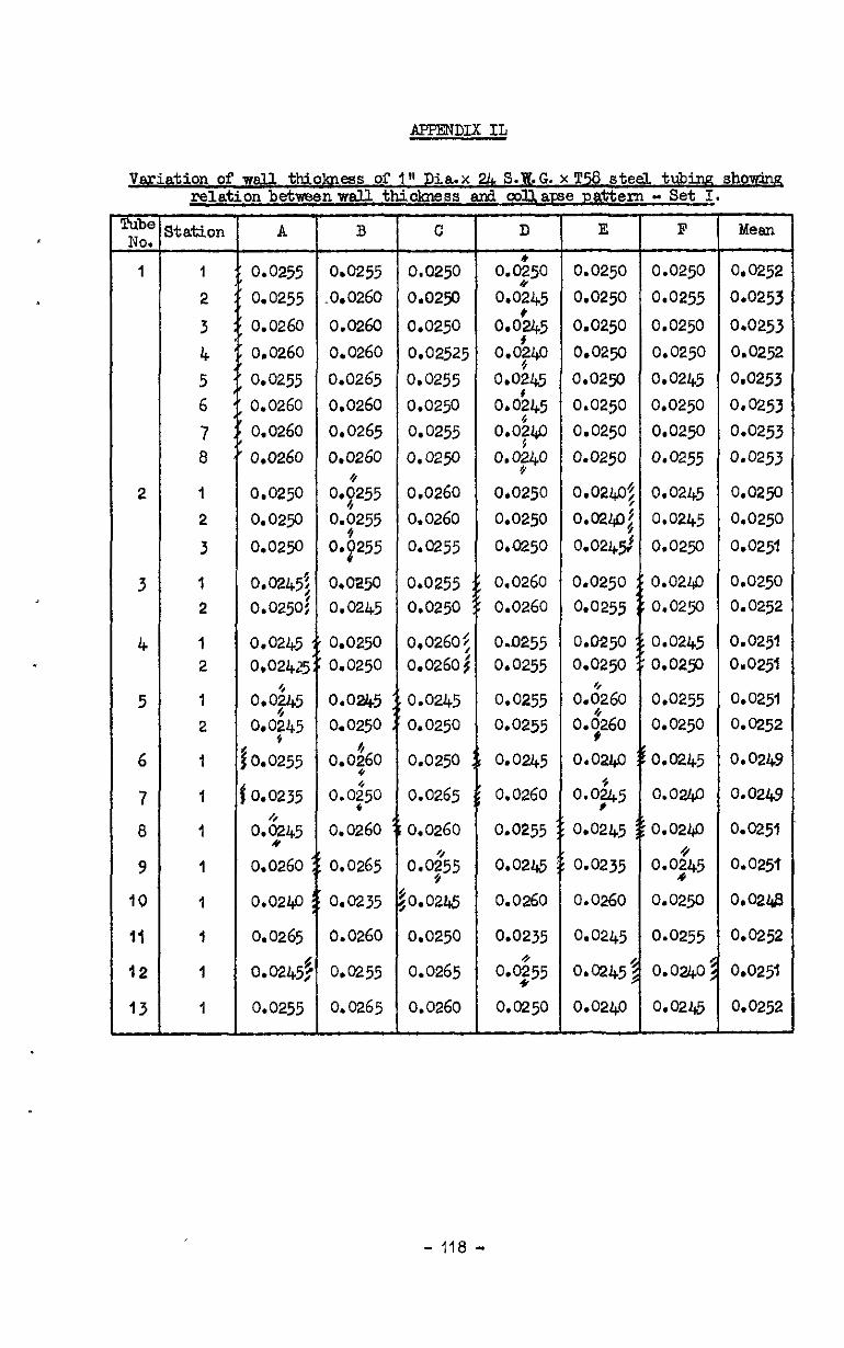
A.PFENDIx IL
Variation of wall thio~ess of I" Dia.x !& S.&G. x T% steel tubiq relation betweenwail tbdtiss ad cdlarse pattern - Set I
m
NO, -
1
2
3
4
5
6
7
8
9
10
Ii
12
13 -
itation
1
2
3
4
5 6
7 8
1
2
3
1
2
1
2
1
2
1
1
1
1
1
I
1
1
A
0.0255
0.0255
0.0260
0.0260
0.0255
0.0260
0.0260
0.0260
0.0250
0.0250
0.0250
0.0245? 0.0250!
0.0245 0.02425
0.0;+5
O.Of45
0.0255
0.0235
0.$45
0.0260
0.0240
0.0265
o&245$
0.0255
B
0.0255
,0.0260
0.0260
0.0260
0.0265
0.0260 0.0265
0.0260
0.!255
o.;255
0. 255 P
0.025c 0.0245
0.0250 0.0250
0.0245 0.0250
0.0;60
0.0{50
0.0260
0.0265
0.0235
0.0260
0.0255
0.0265
c
0.0250
0.0250
0.0250
0.02525
0.0255
0*0250
0.0255
0.0250
0.0260
0.0260
0.0255
0.0255 0.0250
0*0260~ 0.0260;
0.0245
0.0250
0.0250
0.0265
0.0260
0.0;55
0.0245
0.0250
0~265
0.0260
D- o.os50
0*0;45
o.o’u5
o.o:l$l o.oi45
0.0545 o.o~w, 0.940
0.0250
0.0250
0&?50
0.0260
0.0260
0.0255 0.0255
0.0255
0.0255
0.0245
0.0260
0.0255
0.0245
0.0260 0.0235
o.oz55
0.0250
E
0.0250
0.0250
0.0250
0.0250
0.0250
0.0250
0.0250
0.0250
0.0250 0.0255
0.0250 0.0250
o.G260
0.$260
0.0240
0.0,&5
0.0245
0.0235
0.0260
0.0245
0.0245
0.0240
I?
0.0250
0.0255
0.0250
0.0250
0.0245
0.0250
0.0250
0.0255
0.0245
0.0245
0.0250
0.0240 0.0250
0.0245 0.0250
0.0255
0.0250
0.0245
0.02lgJ
0.0240
0.0;45
0.0250
0.0255
0.024.0
0.0245
#howing
Mesn
0.0252
0.0253
0.0253
0.0252
0.0253
0.0253
0.0253
0.0253
0.0250
0.0250
0.0251
0.0250
0.0252
0.0251 0.0251
0.0251
0.0252
0.0249
0.0249
0.0251
0.0251
0*02l&J
0.0252
0.0251
0.0252
- 118 -
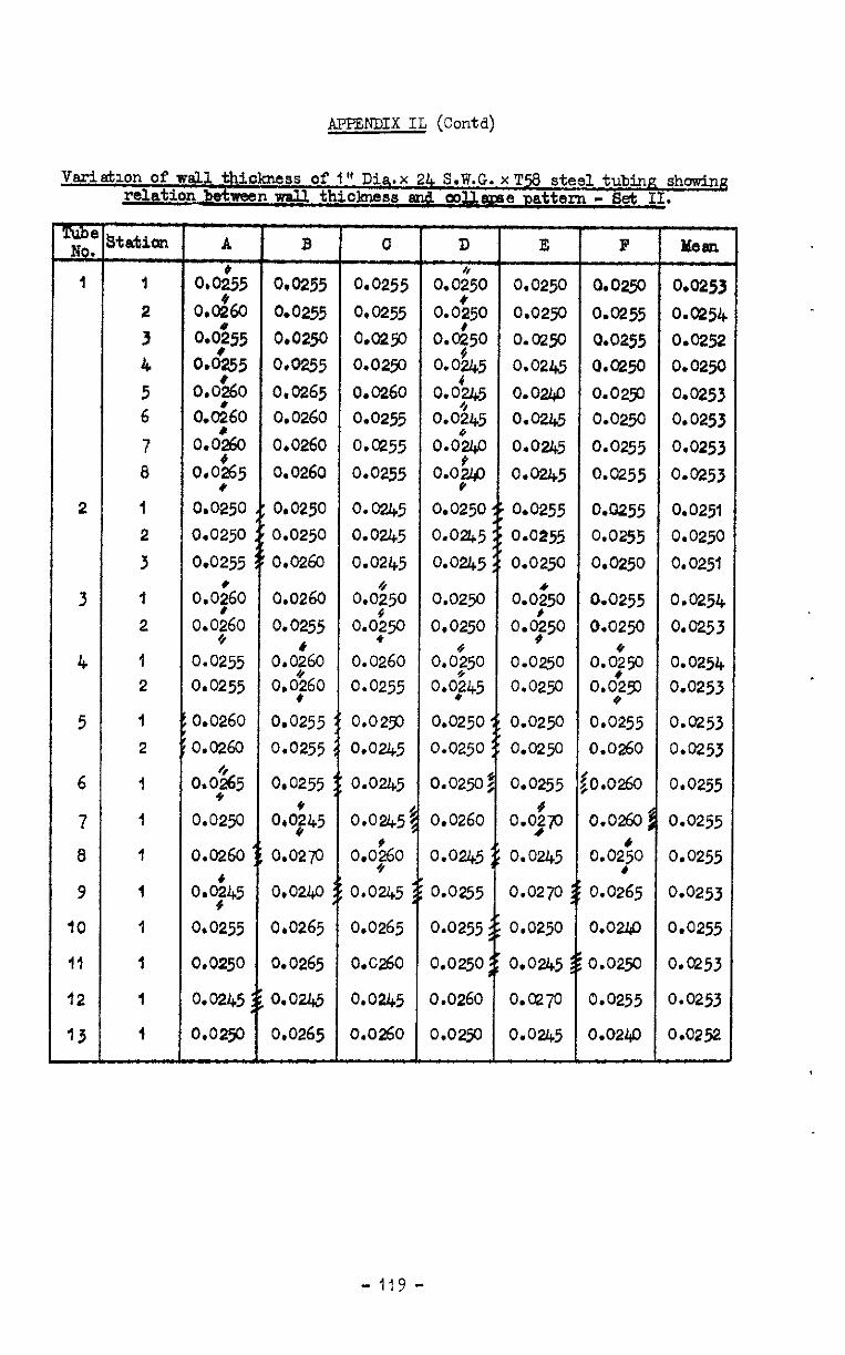
Amm-ixx IL (conta)
Vsriattlon of wall thiokness of 1" Dia.x 24 S.W.G.xTs steel tubing showing relation btwwn w-all thickness and CoUavre Dattem - Set II.
Te 8tation A B C D E F wml
I I 0.0:55 0.0255 0.0255 0.0;50 0.0250 0.02g 0.025j
2 0.0&0 0.0255 0.0255 0.0:50 0.0250 0.0255 o.v254
3 0455 0.0250 a.0250 0.0!?50
0.0!?45
O.o2f$J 0.0255 0.0252
1 0.0255 o*O255 0.0250 0.0245 0.025‘0 0.0250
5 o,o’&o 0.0&o
0.0265 0.0260 0.01245 O.Oli&
o.oup 0.02yJ 0.0253
6 0.0260
o.o~ko
0.0255 O.MW 0.0250 0.0253
7 0.0260
o*os65
0.0255 o.o~&,o 0.0245
o.otg
0.0255 0.0253
a 0.0260 0.0255 0.0245 *
0.0255 0.0253
2 1 0.0245 0.0255 0.0255 0.0251
2 0.0245 o-0255 0.0250
3 O&?&l 0.0245 0.0250 0.0251
3 -t 0.0;60 0.0260
o.o,$o
o.ogo 0.0250 0.0,;50 O.0255 0.0254
2 0*o255 0.0250 0.0250 0.0253
4 1 0.0255 0.0:60
O.O$ 0.0$50
0.0260 0.04250 0.0250 o.o;w 0.0254
2 0.0255 0.0>60 0.0255 0.0;45 0.0250 0.029) 0.0253 $
5 d to.0260 0.0255 0.0250 0.0250 0.0250 0.0255 0.0253
2 ;0.0260 0.0255 0.0245 0.0250 0.02p 0.0260 0.0253
6 1 0.0;$5 0.0255 0.0245 0.02502 0.0255 $0.0260 0.0255
1 0.0250 0,0&5 0.0245% 0.0260 0.0&o /
7 0.0260$ 0.0255
a 1 o.o;~o 0.0245 ;; 0.0245 LO:;0 0.0255
9 I 0,02l+o :; 0.0245 :; 0.0255 0.0270 3; 0.0265 0.0253
10 1 0.0255 0.0265 0.0265 0.0255 0.0250 0.0240 0.0255
II 1 0.0250 0.0265 o.a260 0.0250 0.0245 go.0250 0.0253
o.ozi@ 0.0245 0.0260 o.ce70 0.0255 0.0253
0.0265 0.0260 0.0250 0.0245 0.0240 0.0252
- 119 -
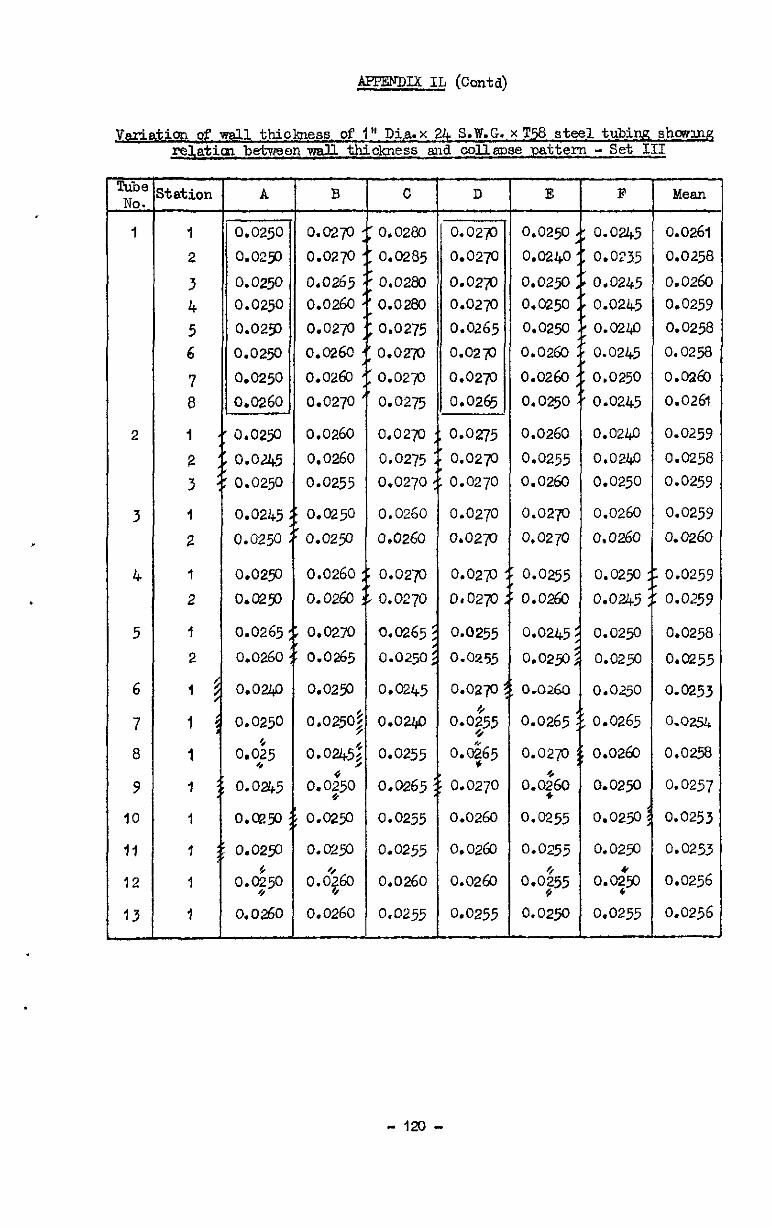
AFPEVDUL IL (Contd)
Variation of wall thickness of 1" Di&x 24 S.W.G.xT% steel tubiw? shmmg rell,atim between vdl thickness and oollapse pattern - Set III
EiG No. -
1
2
3
4
5
6
7
8
9
IO
17
12
13 -
tatiol
1
2
3 4
5 6
7
8
I
2
3
I
2
1
2
1
2
1
1
I
I
I
7
1
7
A
0.0250
0.029
0.0250 0.0250
0.0253
0.0250
0.0250
0.0260
0.0250
0.0245 0.0250
0.0245
0.0250
0.0250
O.CpD
0.0265
0.0260
0.0240
0.0250
od$5
0.0245
O.CEO
0.0250
o.ogo
0.0260
B
0.0270
0.02p
0.0265 0.0260
0.0270
0.0260
0.0260
0.0270
0.0260
0.0260
0.0255
0.0250
0.02!3
0.0260
0.0260
0.0272
0.0265
0.0250
0.0250
0.0245
0.0;50
0.0250
0.0259
0.+3
0.0260
C
0.0280
0.0285
0.0280 0.0280
0.0275
0.02-p
0.0233
0.0275
0.02p
0.0275
0.0270
0.0260
0.026o
0.0270
o.oqo
0.0265
0.0250
0.0245
0.024o
0.0255
0.0265
0.0255
0.0255
0.0260
0.0255
D
0.02p
0.0270
0.023
0.0270
0.0265
0.027-l
0.02p
0.0265
0.0275
0.027o
0.0270
0.0270
0.0270
o.ozp
DaO27u
0.0255
0.0255
o.oap
0.0;55
0.965
0.0270
0.0260
0.0260
0.0260
0.0255
E
0.0250
o.o240
0.0250 0.0250
0.0250
0.0260
0.0260
0.0250
0.0260
0.0255
0.0260
0.0270
0.0270
O-0255 0.0260
0.029
0.0260
0.0265
0.0270
o.o$o
O.@55
0.0255
0.0;55
0.0250
F Mean
0.0245 0.0235
0.0245
0.0245
O.O2l@
0.0245
0.0250
0.0245
0.02@
o.o2l@
0.0250
0.0260
0.0260
0.0261
0.025s
0.0260
0.0259
0.0258
0.0258
o.oaal
0.0261
0.0259
0.0258
0.0259
0.0259
o. 0260
0.0250 0.0259
o.out5 o.oz59
0.0250 0.0258
0.0250 0.0255
0.0250 0.0253
0.0265 o.o.?iy&
0.0260 0.0258
0.0250 0.0257
0.0250 0.0253
0.0250 0.0253
o.o$c 0.0256
0.0255 0.0256
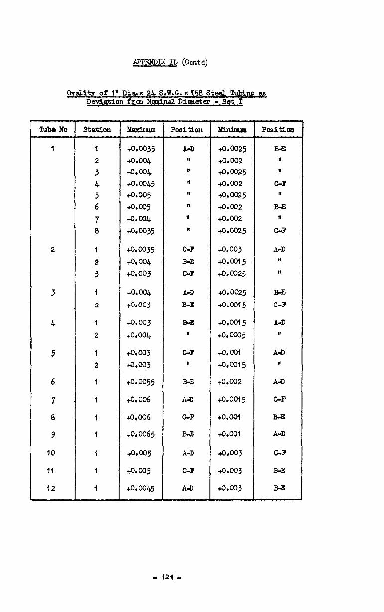
APPEND= It (Contxi)
Ovalits of 1" Di&x 24 S.W.G.xT58 St& T&km as Detiation fran Ncmln.9Dfeudcr - Set I
Tuba No station - Position Aflnirnun PaSitioD
1 1 ~.~35 A-D +0.0025 B-E 2 +o.O& " to.002 ,I
3 to.004 " to.0025 II
4 to.ool& n +o.c02 C-F 5 to.005 * to.0025 n
6 to.005 n +0.002 B-E
7 *0.004 " to.002 n
8 to.0035 n &0025 C-F
2 I +o.c035 C-F to.003 A-D 2 to, 004 B-E to.ool5 II
3 to*003 C-F to.0025 n
3 I +0.004 A-a) to.0025 B-E
2 to.003 B-E to.0015 O-F
4 I io.003 B.E to.0015 A-D
2 to.004 II to.ooo5 ,I
5 1 +0.003 C-F to.ool A-D
2 to.003 ,I to.0015 II
6 1 to.0055 B-E to.002 AD
7 1 +o. 006 A-a lQ.ool5 G-F
8 1 tQ.006 C-F t0.oo-l B-F4
9 I tom65 B-E to.ca A-D
IO 1 to.005 A-D to.003 C-F
II I to.005 C-F +0.003 B-E
12 I to.0045 Adl to.003 Bd3

APPENDIX IL (Conta)
,Oveli~ of 1" Diax 2t+ S.W.G. xT58 Steel lhbes 89 Deviation fmm Nmuinal Diameter - Set II
Tube No
1
2
3
4
5
6
7
8
9
IO
11
12
statial
I
2
3
I
2
1
2
1
2
1
I
1
1
I
I
I
Mtimum
+o.w
to. 0045 to.ocY&
to.004
+o.a35 to.0035
+o.c04
to.003
to. 004 to.oc&
to.0045
to.0045
to.0045
to.005
to.ocd+
to.oo4
+0.004
+0.0045
to.005
+0.0055
&co5
+0.0055
to.005
43.005
Position
A-I) "
II
cw n
A4l II
cw
E-B
F-o
F-C
A-D
E-B
0-F
A4
G-F
Mininnlm
+o.m35 to.003 io.003
to.0025
to.002
tO.0025
+0.0025 to.o02!5
+0.0035
to.0035 to.0035
+0*~35
to.003
to.003
+wx3
to.003
+a0035
+0.@35
to.co2
tom25
+cLoc25
+o.CQ25
+a003
4.003
Positim
A-D
C-F II
I,
B4 II
"
"
B-FA II
"
A-D I,
E-B n
E-B
C-F
E-B
A-D
O-F
O-F
BJi
B-E
BE
-122-
lhbe %o
I
2
3
4
5
6
7
6
9
IO
11
12
APPENDIX IL (c&a)
hititv of 1" D1a.x 24 S.W.G.x T58 Steel Tubes 89 Deviaticm f'rom Nonnnal Diwetex - Set III
Station
1
2
3
4
5 6
7 8
1
2
3
I
2
1
2
1
2
1
I
I
I
I
I
I
--
Maximum Position
40.0065 E-E
+o.w5 0-F
+o.o%5 "
+o.c065 I,
+o.ocd E-E
+O.W6 "
+o. 036 n
+&co6 0-F
+o. 0055
to.006
+0.006
+o. co5
+o.o055
+o. 004+
*o.w
to.ocv+
+o.w
+o.ccJ;
to.005
to.006
t-O.036
A4
C-F II
A-D
SE
0-F lb
A-D
GF
B-E
0-F
co.005
+0.006
+&co5
A-D
A-D
&F
abinimun
to.cQl
co.003 to.ool
to. WI
+o.oGl5 to.002
+0.0025
to1002
+o.o03
to.002
to.ooi 5
+o.o025
+0.002
+a0025
+0.0025
+0.003
to.003
+o.o03
4.0.002
to.001
to.ool
to.wl
to.ool
tO.001
- 123,
AETEiimIX IL (contd)
. Mechanical Properties of I" Dia. x 24 S.W.G. x T.58 Steel Tubing
Spedmen Direction E x 0.4% o.q% a.% of Grain ,,-6 Laps P.S. P.S. P.S.
Max. Elong. NO. Stress $ on I"
I L 28.6 12.6 45.0 49.4 53.6 58.4 15.0
T 25.6 6.0 43.4 50.6 57.4 61.7 3.0
Relation between Mechanical and Pressure Test Specimens
Since all the pressure test specimens were out from the s~mc length of tube, the results given above were applied in eJ.1 cases.
- 124 -
APPENDIX IL (Cc&d)
Unifozm IQtemd Pressure Amlied to the Sidw onlv
Tube No Collapse pressure
1.1
2.1
3.1 1.2 2.2
3~2 1.3 2.3
3*3 1*4 2.4 3-4
1.5
2.5
3*5 1.6
2.6
3.6
l-7
2.7
3.7 1.8 2.8
3.8
1.9
2.9
3.9 1.10
2.10
3.10
1.11 2.11
3.11 1.12
2.12
3.12
1040 1075 ICOO
1720 1875 1625
2780
2775
27%' 3180
3050 2950
3520
3730
3450 4530
4.600 WC75 5050
4950
4875
5400 5650
5575 6050
5720
6050 65f.30
6320
6659
6850 739
7200
ajoo
& D
14 II
,I
4
3.0
2.5
2.0
1.5
1.25
1.0
0.85
0.6
0.5
0.4
Attachea: Dr& SW. 75456/R
No. Lobes Forma
2
2
2
2
2
2
3 3 2
3 3 3
3
3
3 4
4 3
4
4
4
4 4
4
4
4
4 3
2
3 I
3 2
2
No. I&es in omplete p=Wery
2
2 2 2 2 2
3
3
3 3 3 3
3
3
3
4
4 3
4 4
4
4 4
4
4
4
4 6
6
4 6
5 6
8
- 125 -
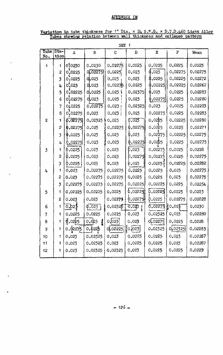
fwmDIxIM
Variation in tubs thickness for 1" Dia. x 24 S.T.G. x D.T.D.460 Light Alloy Tubes showing relation between wall thickness and collapse pattern
Tube &
1
2
3
4
5
6
7
0
9
IO
11
12
Ez ;i"
1
2
3 4
5 6
7
8
1
2
3
4
1
2
3 1
2
3
1
2
1
1
1
1
1
1
1
A 0!0230
01.0225
Of0225 01023
of02225 0102275 020225
oio2275
0.023
3.023
0.02275
3.02225
3.023
3.0225
3.023
3.023
3.023
B
0.0230
0.02275
0.023
0.02325
0.023
0.023
0.023
0.023
0.023
0.023
O.b2275
0.02275
0.02275
0.02225
0.023
m
0.0225
0.02325
0.02325
SET
C
0.022$
0.022$ 0.023 1
0.022%
0.023 ‘c
0.023 1
0.023;
0.023;
0.023
0.02275
0.023
0.023
0.023
0.023
0.023
0.02275
0.02275
0.02275
0.0225
a.02279
0.0232
0.0225
OpsJ
01.02225/l’
0.023
0.023
0.02325
1
D
0.0225
0.023
0.023 0.0225
0.0237:
0.023
0.0232:
0.023
~023
.0227:
e
.023
.0227:
0.023
0.023
O.@J
0.0225
0.0225
0.023
E 0.0225
0.023
0.02275
0.02275 0.02274
0.0225t
0.0225'
0.0225
0.02225
p.0227q
0.02325
OB
0.02325
0.0225
0.0225
0.0225
F Mean
0.0225 0.0225
0.02275 0.02275 0.02225 0.02272 0.02225 0.02262
0.0225 0.02283
0.0225 0.02280
0.0225 0.02283
0.0225 0.02283
0.02225 0.02280
0.0225 0.02271
0.02225 0.02275
0.0225 0.02275
0.0225 0.0228
0.0225 0.02275
0.02225 0.02282
0.023 0.02275
0.023 0.02275
0.0225 0.02254
0.0225 0.0223
0.02275 0.02228
0.02 t
0.0230
0.023 0.02280
0.0225 0.0228
O@ 0.02283
0.023 0.02287
0.023 0.02287
0.0225 0.0229
- 126..
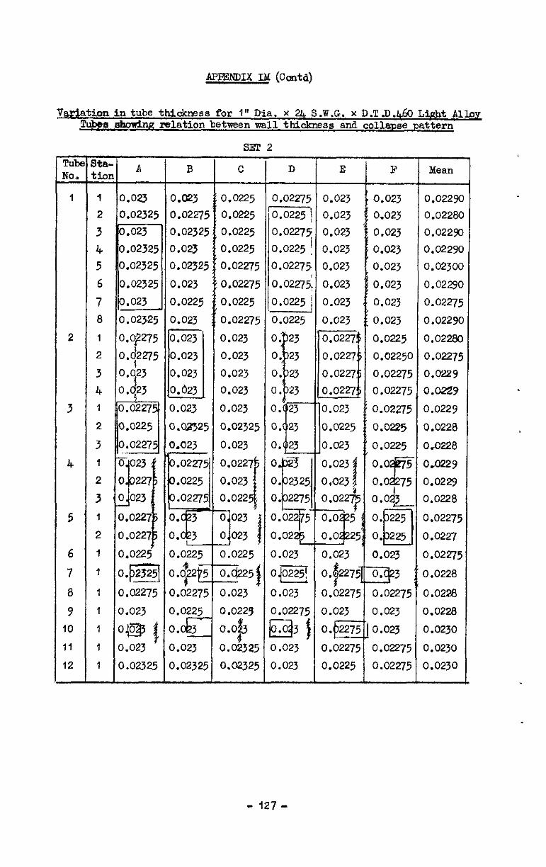
APPENDIX Ild (conta)
V&&atiwintube thickness i'or I" Dia. x 2l+ S.W.G. x D.T.D.l& M&t Allay rlIb#8 &WWk mlation between ml1 thickness and Collapse pattern
ml! 2
- 127 -
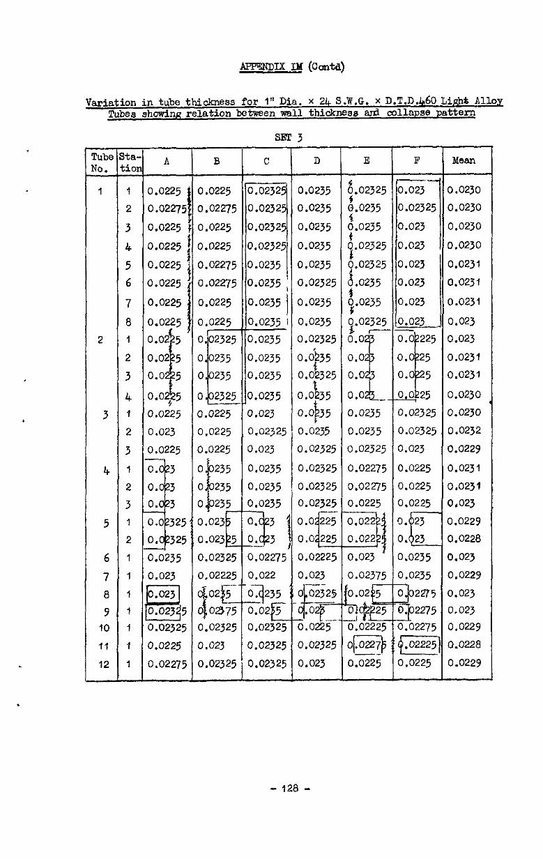
.
Variation in tube thickness for I" Dia. x 24 S.W.G. X D.T.D.460 Li&t 8110~ Tubes showing relation b&men wall thioknsss sn?. collapse pattern
s-m 3
FIG im -
1
2
3
4
5
6
7
8
1
2
3
4 1
2
3
1
2
3
1
?
1
1
1
1
1
1
1
A B
0.0225
0.02275
0.0225
0.0225
0.0225
0.0225
0.0225
0.0225
0.0225
0.02275
0.0225
0.0225
0.02275
0.02275
0.0225
0.0225
0.0225 0.0225
0.023 0.0225
0.0225 0.0225
3.0235 1.02325
3.023 1.02225
5 3.02325
3.0225
3.02275
1.02325
I.023
3.02325
C D
10.0235
iO.0235
;O.o235
0.0235
0.023
0.02325
0.023
0.0235
0.0235
a.0235
0.0235
0.0235
0.0235
0.0235
0.0235
0.02325
0.0235
0.0235
0.02325
o.db35
f2 0.0 325
o.ob35
0.0 35 P 0.0235
0.02325
0.02325
0.02325
0.02325
0.022
03235 :
0.02 5 E
0.02325
3.02225
3.023
0.02325 9.02325
0.02325 0.023
E
6 .02325
i.0235
b.0235
8.02325
I.02325
6.0235
4.0235
0.0235
0.0235
0.02325
0.02275
0.02275
0.0225
1.02375
3.02225
lp-$ -- 3.0225
F Mean
0.02325 0.0230
0.02325 0.0232
0.023 0.0229
0.0225 0.0231
0.0225 0,023l
0.0225 0.023
0.0229
0.0228
I.0235 0.023
1.0235 0.0229
I.02275 0.0229
E] 0.0228
1.0225 0.0229
- 128 -
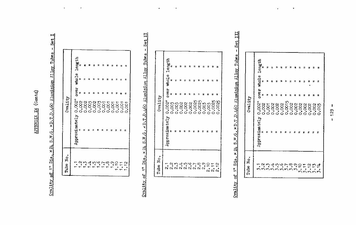
.
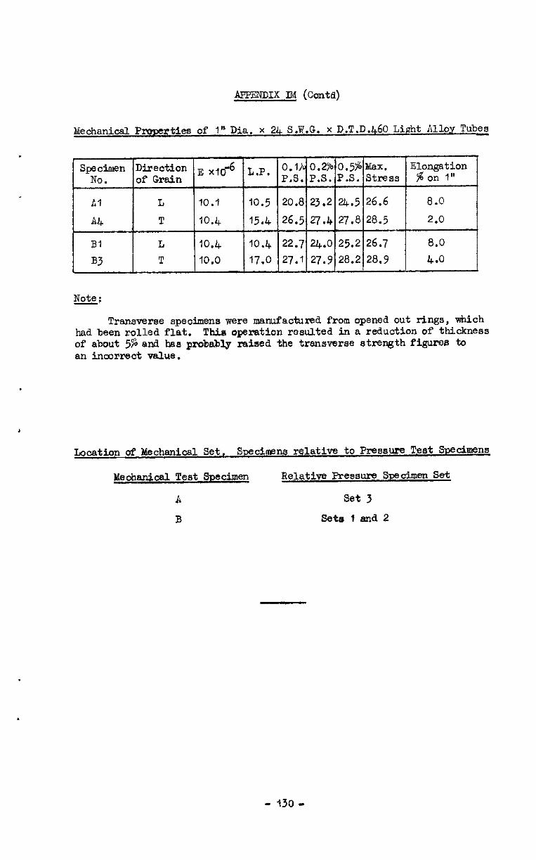
APPENDIX llvl (ccmta)
Mechanical Prvperties of 1" Dia. x 24 S.W.G. x D.T.D.460 Light Alloy Tubes
Transverse specimens were manufactured from opened out rings, which had been rolled flat. Thie opemtion resulted in a reduction of thickness of about 5% and has probably raised the transverse strength figures to an incorrect value.
Location of Mechanical Set. Swcim?ns relative to Pressure Test SDedmms
Meohanical Test S13ecimen Relative Pressure Specimen Set
A set 3
B sets t and.2

Results c& Tests on I" Dia.x24 S.W.G.xD.T.D.460 Liprht Alloy Tubes under unifozm external pressure applied to the side 0n.l.y
Corrected I! Number Lobes Number Lobes in Tube No. collapse aokally coarplete
pressure D fOl7Ed PefiPbly
1.1 280 14 2 2 2.1 206 1, I, 3.1 280 4.2 388 5 2 2 2.2 388 II I, 3.2 370 II 8,
::; 518 560 4 2 n 2 I, 3.3 490 ,I II
9.4 850 3 3 3 :::: 760 778 II ,I 11 ”
1.5 1020 2 2 3
25’ 1050 990 : i 3
1.6 1620 I.5 2.6 1580 t: tt 3.6 1410 4 4
l Results unreliable
Attached: Drg. SNE.7513dR
- 13t -
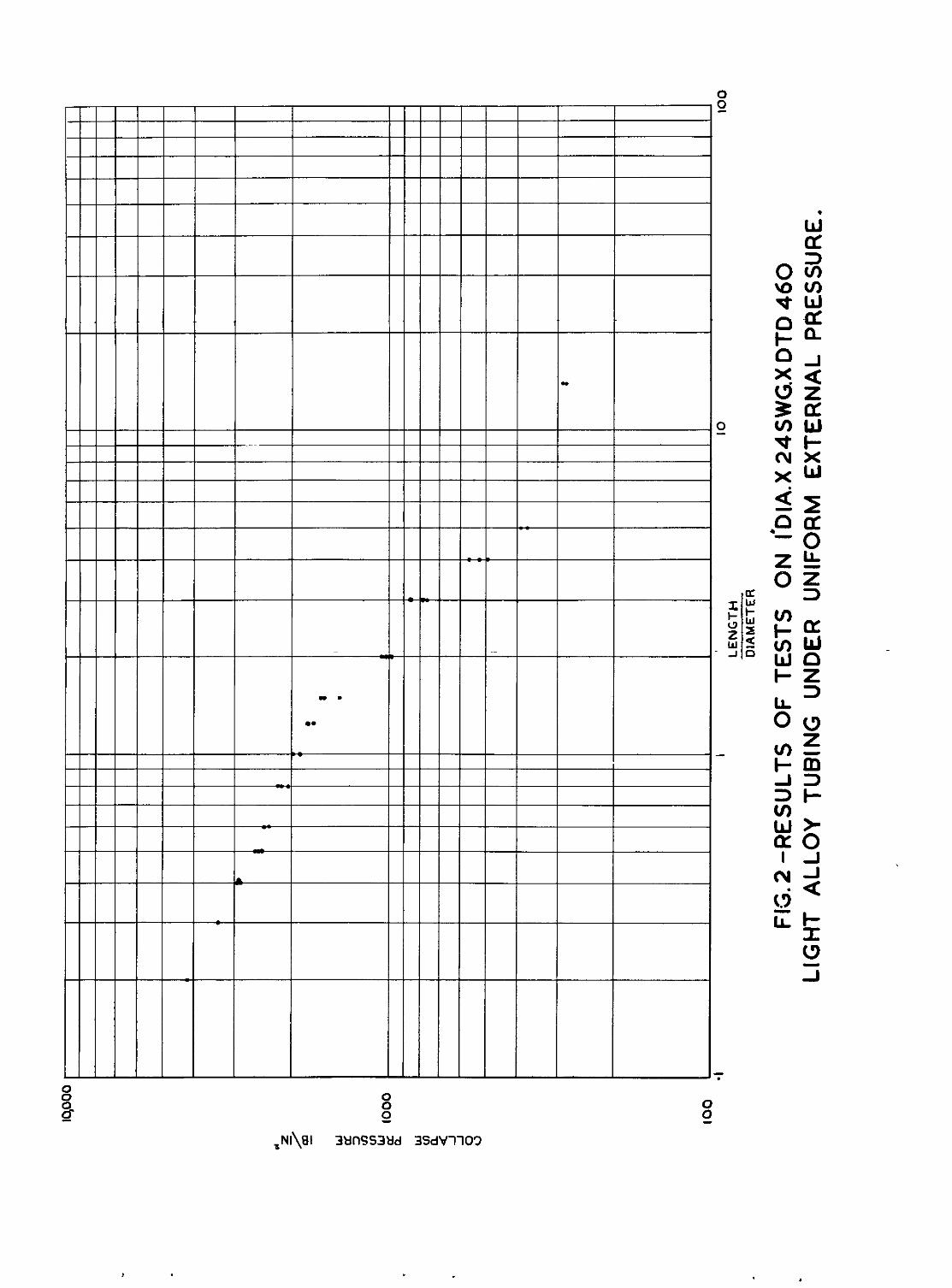
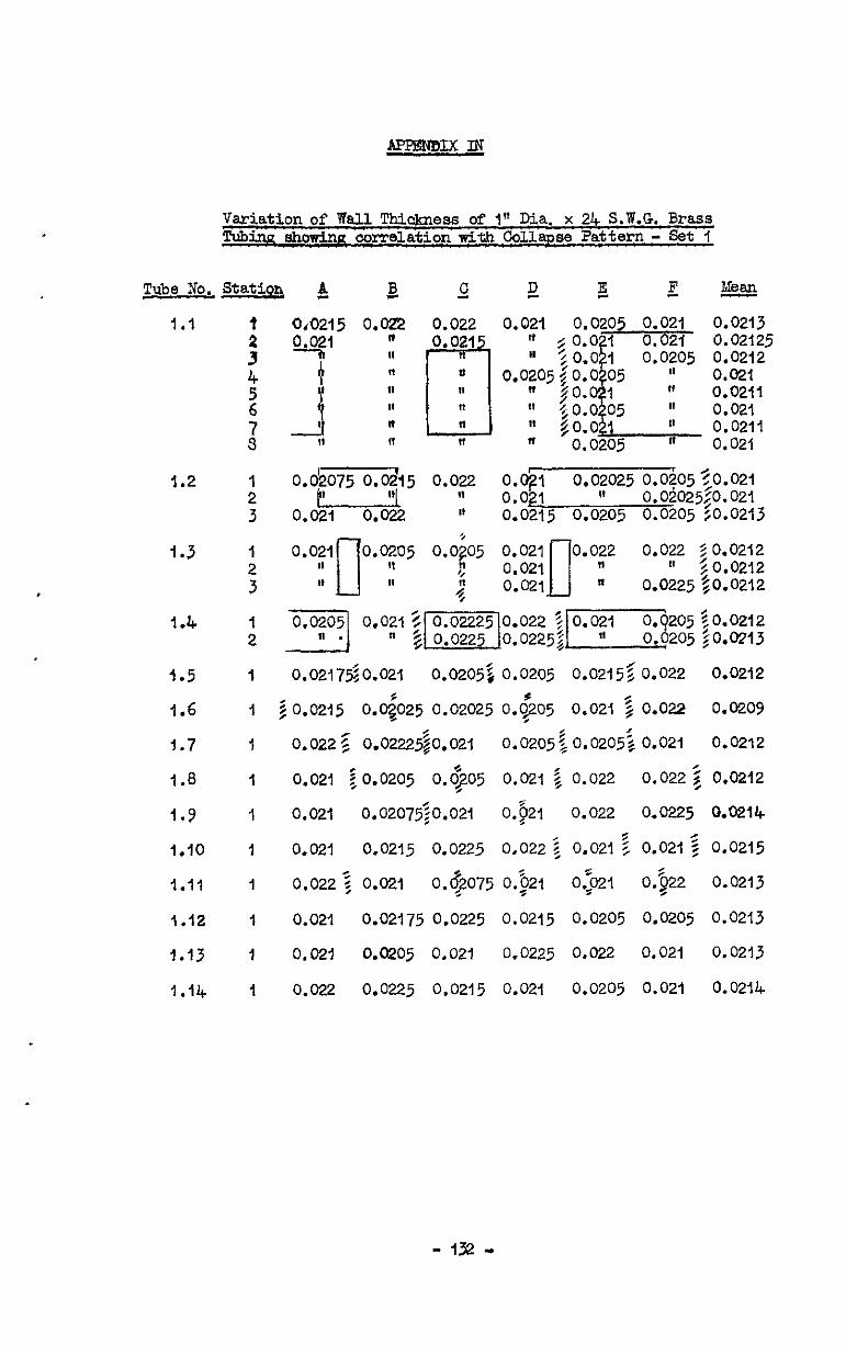
Variation of Wall Thickness of I" Dia. x 24 S.W.G. Brass Tubinn showinn correlation with Collapse ?attern - Set f
1.1
1.2
1.3
1.4
3.5
1.6
j.7
1.8
I.9
1.10
1.11
1.12
1.13
1.14
: ;1 : 97
: 3
: 3
: 1 1
1
I
1
I
1
1
1
1
0.021 0.02125 0.0205 0.0212
-4 “,I-$~ go;o$l- It 0.0211 0.0205 N 0.021
0.021 0.02u5 0.0;05 II 1, II II *i
9
0.02175~0.021 0.02055, 0.0205 0.0215$0.022 0.0212
2 0.0215 0.0$025 0.02025 0.0205 0.021 5 0.022 0.0209 .
0.022 5 0.02225$0.021 0.0205~0.0205~ 0.021 0.0212
0.021 io.0205 0.6305 I
0.021 2 0.022 0.022 2 0.0212
0.021 0.02075~0.021 0.$21 0.022 0.0225 0.0214
0.021 0.0215 0.0225 0.022 z 0.021 Z 0.021 5 0.0215
0.022 5 0.021 0.$?075 0.$21 0.:021 0.$22 0.0213 -
0.021 0.02175 0.0225 0.0215 0.0205 0.0205 0.0213
0.021 0.0205 0.021 0.0225 0.022 0.021 0.0213
0.022 0.0225 0.0215 0.021 0.0205 0.021 0.0214
- 132 ”
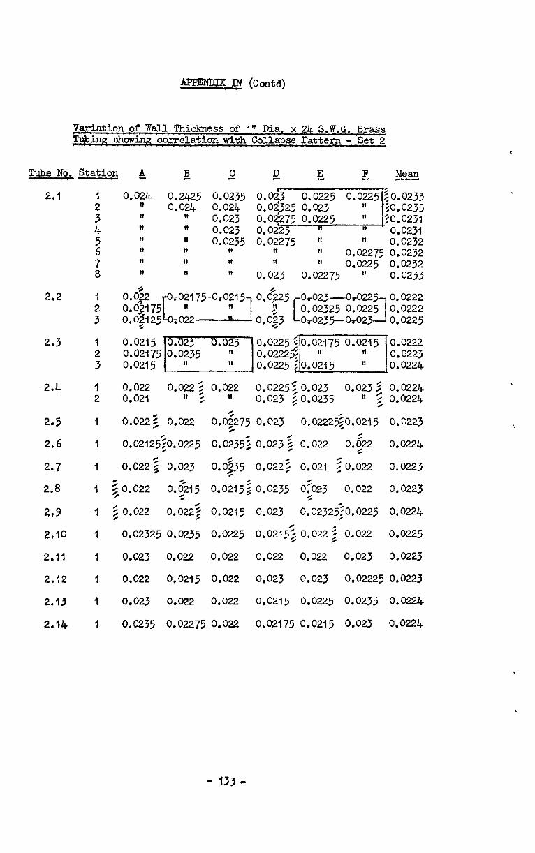
variation of WdLl Thickneqs of 1" Ea. x 24 S.W.G. Brass TUbinn showing correlation with collapse Pattern - Set 2
2.1
2.2
2.3
2.4
2.5
2.6
2.7
2.8
2,Y
2.10
2.11
2.12
2.13
2.14
I
: 4
2
z
1
;
I
:
I 2
1
1
1
1
1
1
1
I
I
0.022 0.022; 0.022 0.0225: 0.023 0.0235 0.0224 0.021 Ia : ” 0.023 iO.0235 ” z 0.0224
0.022g 0.022 0.0:275 0.023 0.02225;0.0215 0.0223
0.02125~0.0225 0.0235; 0.0232 0.022 0.522 0.0224
0.0222 0.023 0.0$35 0.0225 0.021 20.022 0.0223 r
e 50.022 0+5 0.0215; 0.0235 o;O23 0.022 0.0223
5 0.022 0.0222 0.0215 0.023 0.02325;0.0225 0.0224
0.02325 0.0235 0.0225 0.0215; 0.0222 0.022 0.0225
0.023 0.022 0.022 0.022 0.022 0.023 0.0223
0.022 0.0215 0.022 0.023 0.023 0.02225 0.0223
0.023 0.022 0.022 0.0215 0.0225 0.0235 0.0224
1 0.0235 0.02275 0.022 0.02175 0.0215 0.023 0.0224
- 133-
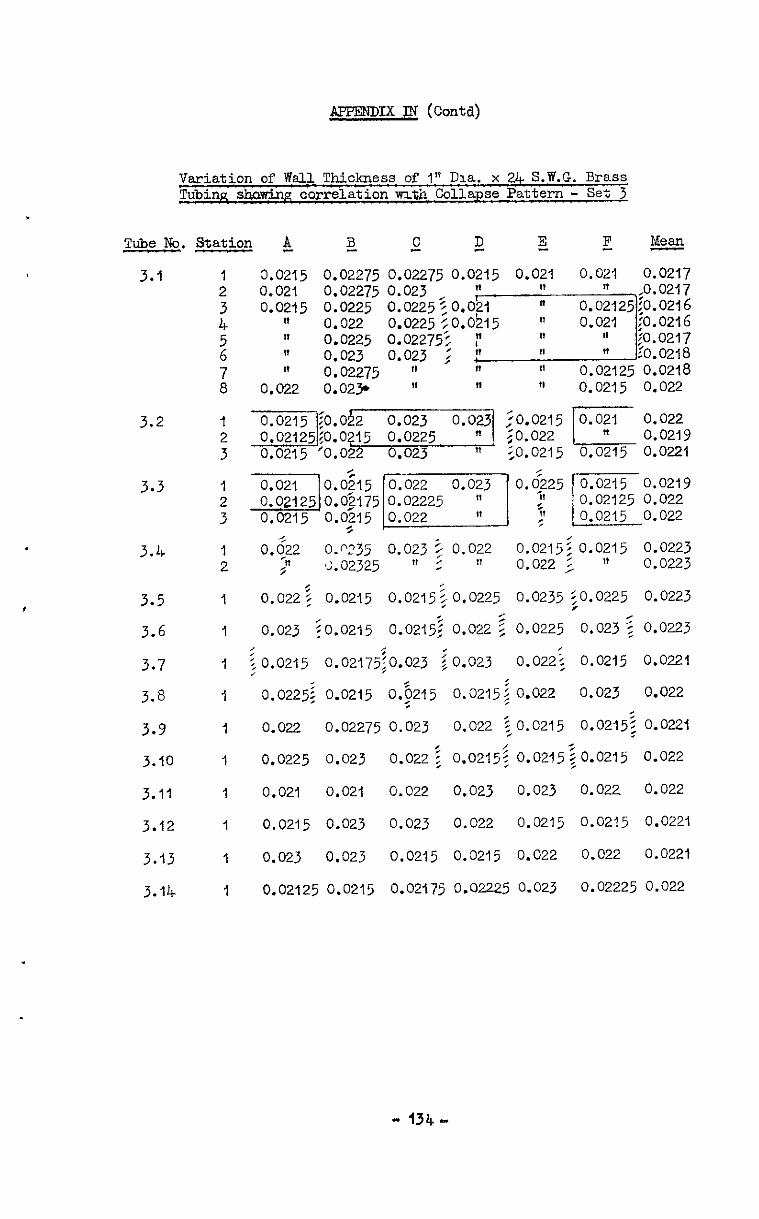
APPENnIx TN (Co&l)
Variation of Wall Thickness of 1%' lha. x 2& S.W.G. Brass Tubinn &wing correlation m.th Collapse Pattern - Set 3
Tube No. Station & E
3.1
3.2
3.3
3.4
3.5
3.6
3.7
3.8
3.9
3.10
3.11
3.12
3.13
3.14
1 2 3 4 ” 0.022
0.0225 0.023
7 ” 0.02275 a 0.022 0.023r
I
c 5! E ?z Neam
0.021 0.021 0.02275 o.oy5 0.y ,, 0.02275 o.oy5 0.y ,, 0.0217 0.0217
II 11 11 0.0215 0.022
0.~235 0.023 3 0.022 0.0215: 0.0215 0.0223 5 '2.02325 " 2 " 0.022 i. 1' 0.0223
0.022? 0.0215 0.0215~ 0.0225 0.0235 SO.0225 0.0223
0.023 :O.O2l5 0.0215: 0.022 z 0.0225 0.023 : 0.0223
iO.0215 0.02175;0.023 io.023 0.022; 0.0215 0.0221 ,
0.0225; 0.0215 0.915 0.0215; 0.022 0.023 0.022
0.022 0.02275 0.023 0.022 to.0215 0.0215: 0.0221
0.0225 0.023 0.022 i, o.o215$ 0.0215$0.0215 0.022
0.021 0.021 0.022 0.023 0.023 0.022 0.022
0.0215 0.023 0.023 0.022 0.0215 0.0215 0.0221
0.023 0.023 0.0215 0.0215 0.022 0.022 0.0221
0.02125 0.0215 0.02175 0.02225 O-023 0.02225 0.022
- 134-
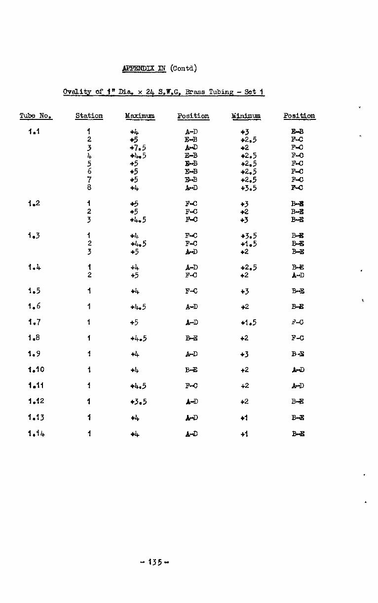
APPENDIX IN (Contd)
Ovslity of I" Dia. x 24 S.W.G. Rmss Tubing- Set 1
.
Tubs No. Station
1.1 I
: 4
1.2
1.3
1.4
I.5
1.6
I.7
1.8
1.9
1.10
i.li
1.12
1.13
1.14
Msximum
+4 +5 +7.5 65 +5 +5 +5 +4
+5 +5 +4.5
+4 +495 +5
+4 +5
+4
+4.5
45
+4.5
+4
+4
+4.5
+3.5
+4
+4
Position
A-D E-B 84 E-B FrB E-B E-B B-6,
F4 F-J.3 F4
FIG
E
A-D F-c
F4
A-D
A-D
B-E
A-D
I343
F-o
A-D
w
A-lD
bH.n.imum
+3 +2.5 +2 +2.5 +2.5 +2.5 +2.5 +3.5
+3 +2 +3
+3.5 +I.5 +2
+2.5 42
+3
+2
+I.5
+2
+3
+2
+2
+2
+I
+i
Position
E-B F.4 F4 B-C F4 F-o F-C F-G
B-B B-E B-E
z B-E
E
B-E
B-!E
A-0
F-C
B.E
A-D
A-D
B-%
B4
I343
t
-135-
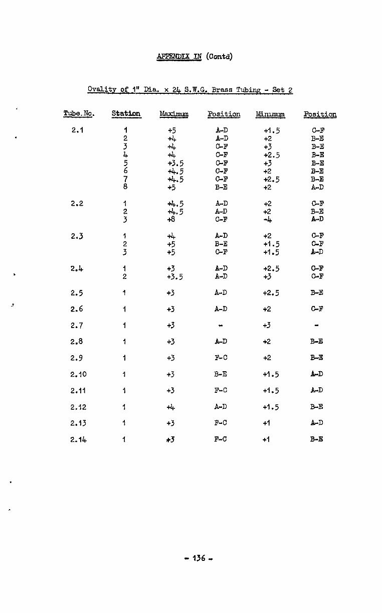
APPENDIX IN (Oontd)
Ovality of 1" Dia. x 24 S.W.G. Brass Tubing - Set 2
Tube.No. Stat&m
2.1 I
: 4
2.2
2.3
2.4 .
2.5
2.6
2.7
2.8
2.9
2.10
2.11
2.12
2.13
2.14
%IcLxbm +5 +4 +4 +4 +3.5
2:: +5
2.5’ t8’
2 +5
+3 +3.5
+3
+3
+3
+3
+3
+3
+3
+4 +3
4-3
Position
A-D A-D C-F C-F C-F GF GF B-E
A-D A-D C-F
A-D B-E GF
;I;
A-D
A-D
"
A-D
F-C
B-E
F-C
A-D
F-C
F-C
Minimum
+I.5 +2 +3 +2.5 +3 +2 +2.5 +2
+2 +2 -4
+2 +I.5 +I.5
+2.5 +3
t2.5
+2
+3
+2
+2
+1.5
+I.5
+1.5
+I
+I
Position
GF B-E B-E B-E B-E B-E B-E A-D
GF B-E A-D
C-F
E
C-F GF
B-E
GF
B-E
B-E
A-D
A-D
B-E
A-D
B-s
-136 -
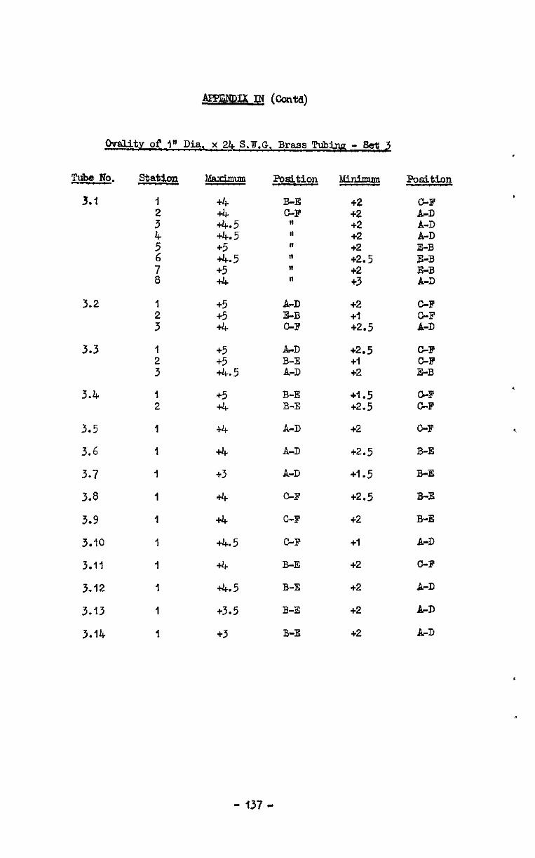
0valit.v of In Dia. x 24 S.B.G. Brass Tub- - M 3
Tube l?o -
3.1
3.2
3.3
3.4
3.5
3.6
3.7
3.8
3.9
3.10
3.11
3.12
3.13
3.14
station
I
: 4 5
i
1
:
I 2 3
I 2
I
I
I
I
1
1
1
1
I
I
+4
2.5 +4.5
E.5 +5 +4
+5
z
+5 +5 +4.5
+5 +4
+4
+4
+3
+4
+4
+4.5
4-4
+4.5
+3.5
+3
Positiqn
B-E C-F II II n II " "
AVD E-B CF
ArD B-E A-D
B-E B-E
A-D
A-D
A-D
C-F
C-F
C-F
B-E
B-E
B-3
B-E
i!G.&E2 +2 +2 +2 +2 +2 +2.5 +2 +3
+2 +I +2.5
+2.5 +I +2
+I.5 +2.5
+2
+2.5
+I.5
+2.5
+2
+I
+2
+2
+2
+2
msitioq
C-F AD
;I:: E-B E-B E-B A-D
C-F
is
C-F
:i
E
C-F
B-E
B-E
B-E
B-E
A-D
C-F
A-D
A-D
&D
- 137 -
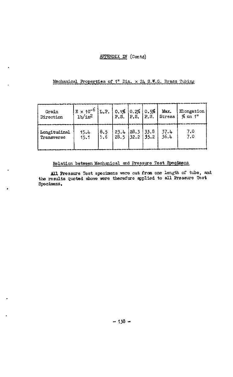
APPENDIX IN (conta)
Mechanical Properties of 1" Dia. x 24 S.W.G. Brass Tubiq
r
Grain E x 1O-6 L.P. Direction lb/in2
0.1% 0.2% 0.596 Max. Ehngation P.S. P.S. P.S. Stress $ on I"
Longitudinal Transverse
23.4 28.3 33.8 37.4 28.5 32.2 35.2 36.4
Relation b&weenMechenical and Pressure Test Speciraens
M.l Pressure Test specimens were cut frcm one length of tube, and the results quoted above were therefore eppliedto allPressure Test SpeCimenS.
- 13a -
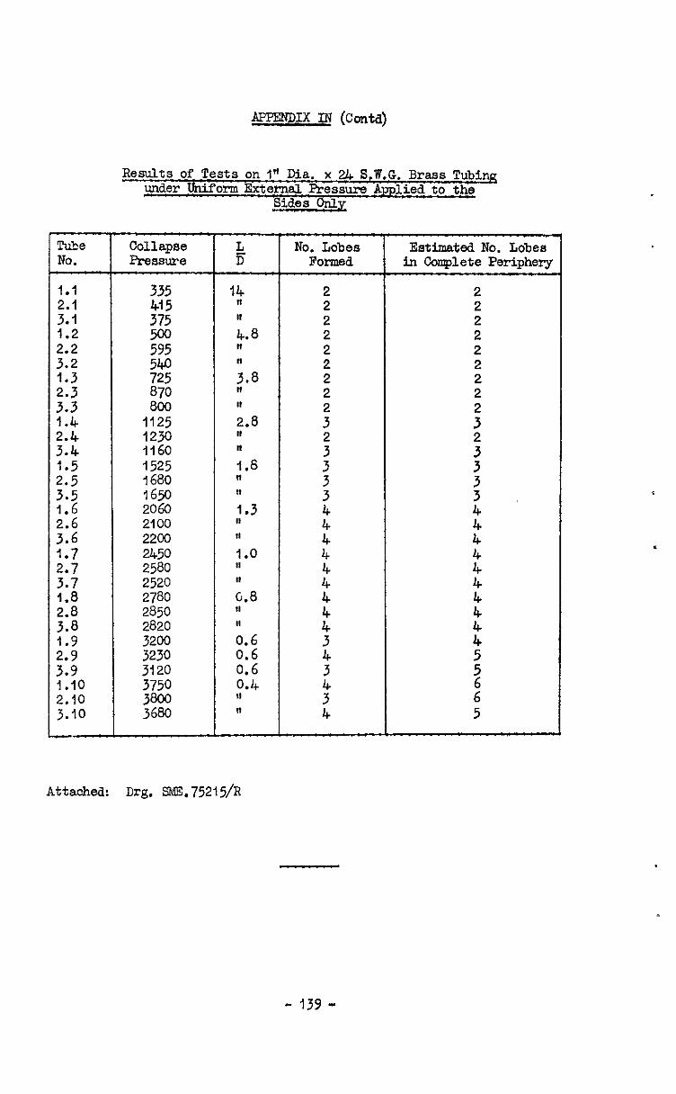
Tube No.
1.1
::: 1.2
f:; .
::: 1.4
:::: I.5
;:;
216 3.6 1.7
;:; .
::i 1.9
::; 1.10 2.10 3.10 --
Results of Tests on I" Dia. x 24 S.W.G. Brass Tubing under Uniform ExternsJ. Pressure Amlied to the
m
Collapse Pressure
No. Lobes Esti&t.ed No. Lobes POl7lEd in Oonrplete Periphery
335 415
;z 595
% 870 800
1125 1230 1160 1525 1680 1650 2060 2100 2200
gz: 2520 2780 2850 2820 3200 3230 3120
;z 3680
” f:
L.8 I,
i.8 II I, 2.8 II ” 1.8 ” I, 1.3 II II I .o II I, (2.8 11 1, 0.6 0.6 0.6 0.4 II ”
2 2 2 2 2 2 2 2
:
:
:
:
t:
:: 4
::
::
z
6" 5
Attached: Dr& =.75215/R
- 139 -
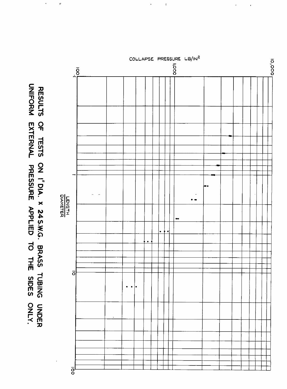
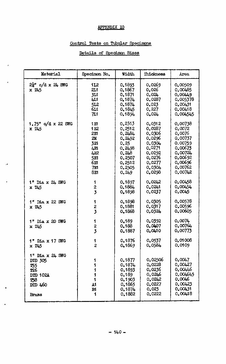
AFFENDIX IO
Contml Tests on Tubdar Sped
Details of S-peaiman S&es
hfa- 1 SpobenNo. 1 Width 15?i&&ww 1 Area
2a" o/dx24SWG x T.45
1.75" o/ii x 22 SiG x T45
l~DiaX24.SNG x T45
1" Diax 22 SWG x T45
I” Diax2OSWG x T45
1" Diaxl7SVG x T45
1 2 3
1 2 3
1
;
1 2
0.1877 l"Diax24SVG m305 1 o.om r55
I 1 0.1874
~2.6 I 0.1893 I 0.0228 0.0236
0.1893 0.0269 0.00509 0.1867 0.026 0.00485 0.1871 0.024 0. @x49 0.1874 0.0287 0.005378 0.1874 0.023 O.oolcjl 0.1845 0,227 0.00418 O.lWt o.ou, O.ww.5
0.25$3 0.0312 0.00738 0.2512 0.0287 0.0072 0.2484 0.0306 0.0076 0.2492 0.02% 0.00737 0.25 0.0304 0.00759 0.2498 0.0271 0.00673 0.268 0.0292 0.00724 0.2507 0.0276 0.00692 0.2512 o.w7 0.006% 0.2505 0.0304 0.00762 O.utY o,ow3 0.00742
0.1897 0.0242 0.1884 0.0241 O.lSse 0.0237
0.1898 0.1881 0.1868
0.0305 0.0317 0.0324
0.389 0.0392 0.188 0.0407 0.1887 o.wo
0.1876 0.0537 0.1869 0.0586
0.0045a 0.00454 0.0045
0.00578 0.005% 0.00605
0.0074 0.00764 0.00773
O.OlOO8 0.0109
- 140-
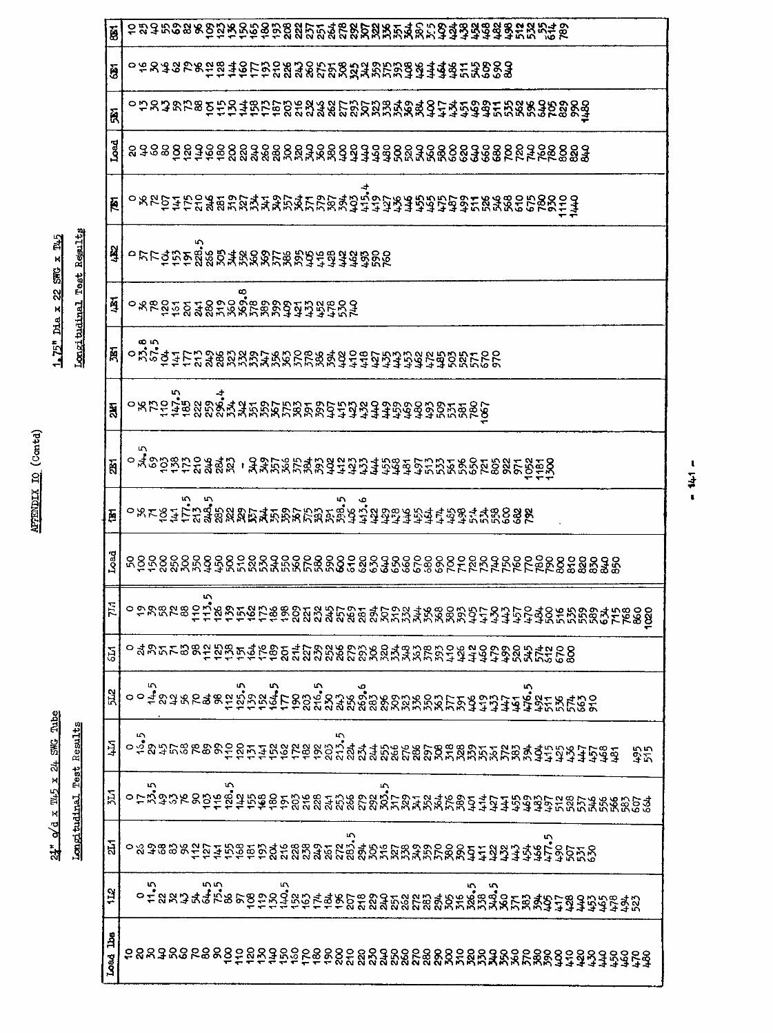
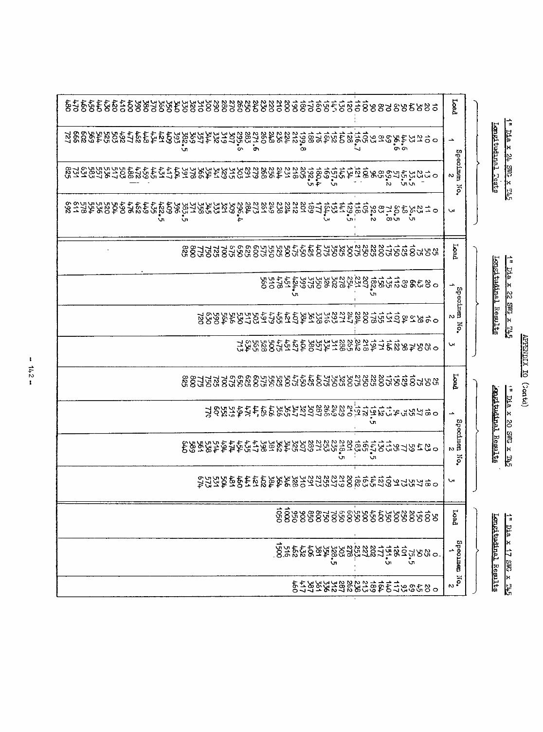
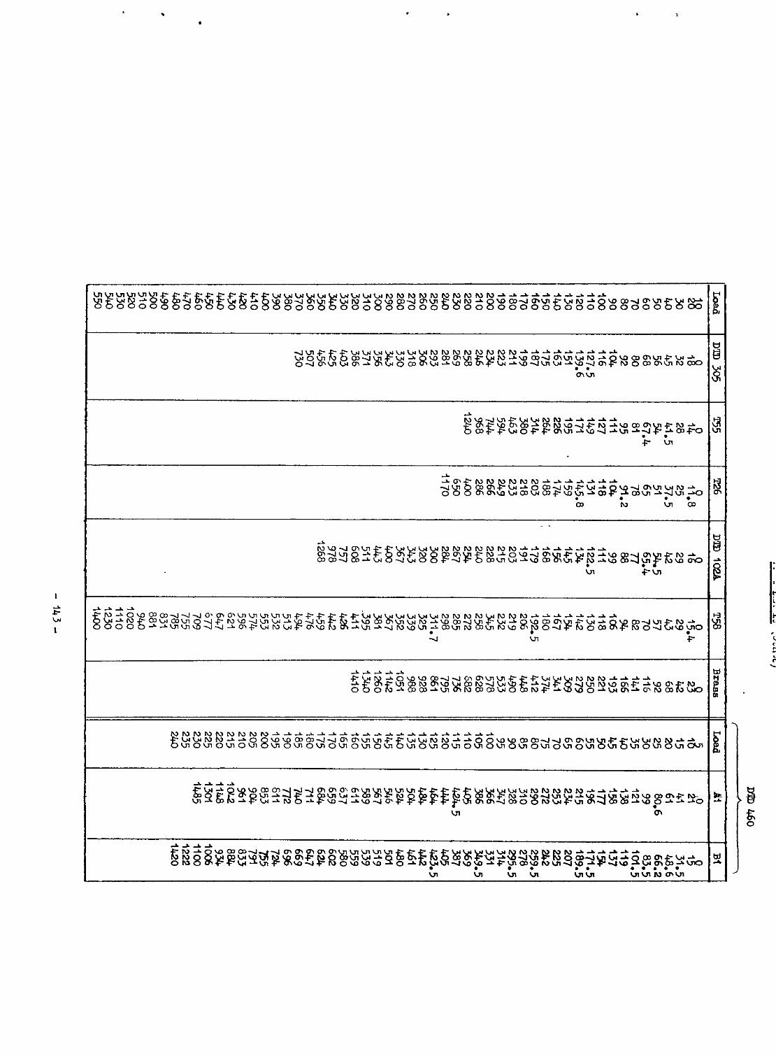

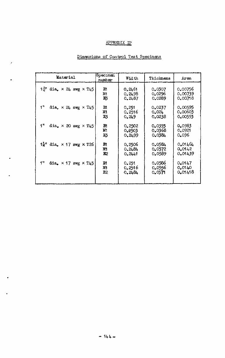
APPENDIX E?
Dimensions of Conk-01 Test Specimens
Matmial
12 dia. x 24 swg x T45
I" dia,x2J+swgxT45
1" dia. x 20 awg x T45
I" dia. xl7 m-g xT45
Width
0.0307 0.00756 0.02% 0.00739 0.0289 0.007t8
0.0237 0.00595 O.Ou, 0.00603 0.0238 0.00593
0.2502 0.0393 0.0983 0.e503 0.0368 0.0921 0.2499 0.0384 0.096
0.2506 0.0584 0.01464 0.2404 0.0572 0.0142 0.2441 0.0589 o.Ol439
0.251 0.0586 O.Ol47 0.2516 0.0556 km40 Q. 2484 0.05-n 0.01418
Thickness Area
- 144-
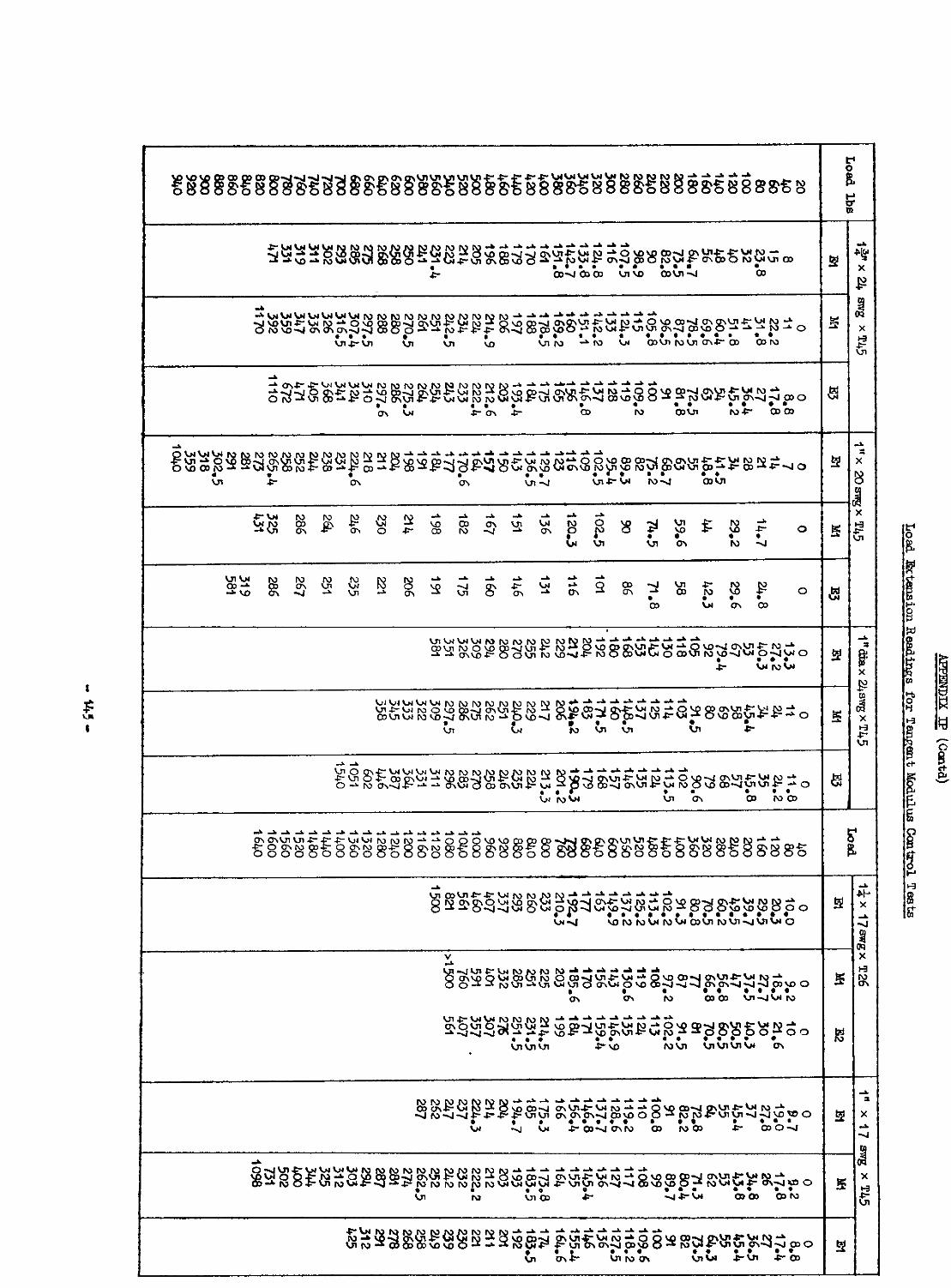

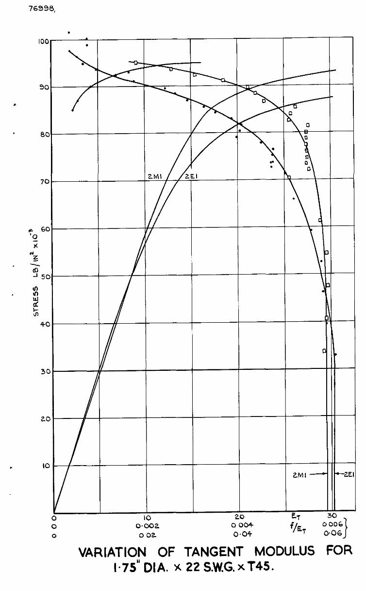
76998,
100
90
c
8C
7C
3(
ZC
I IC
. . \ . 7
.,
l ’
-c -I-
2MI a
3 30
o 006
006
VARIATION OF TANGENT MODULUS FOR l-75” DIA. x 22 S.W.G. x T45.

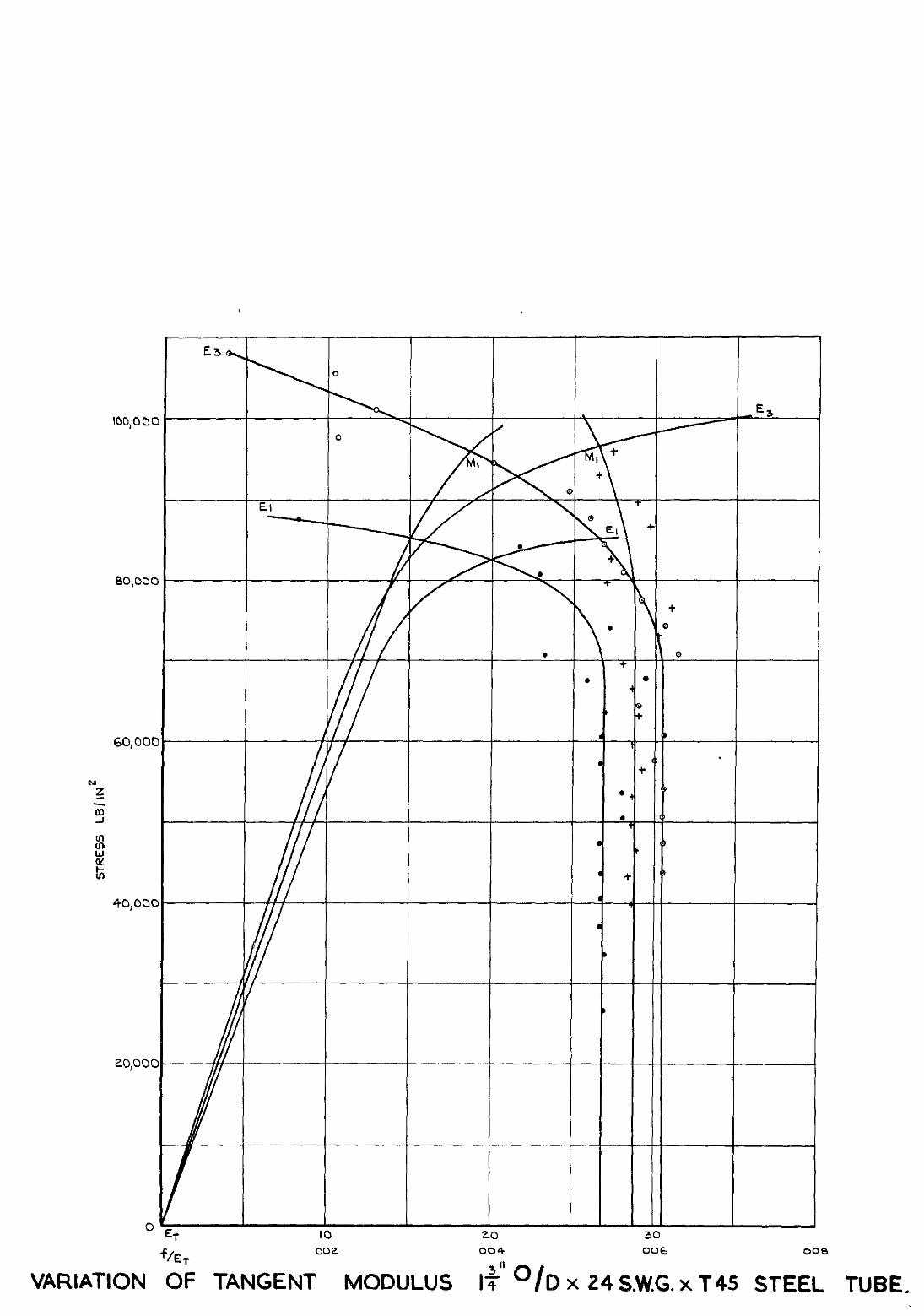
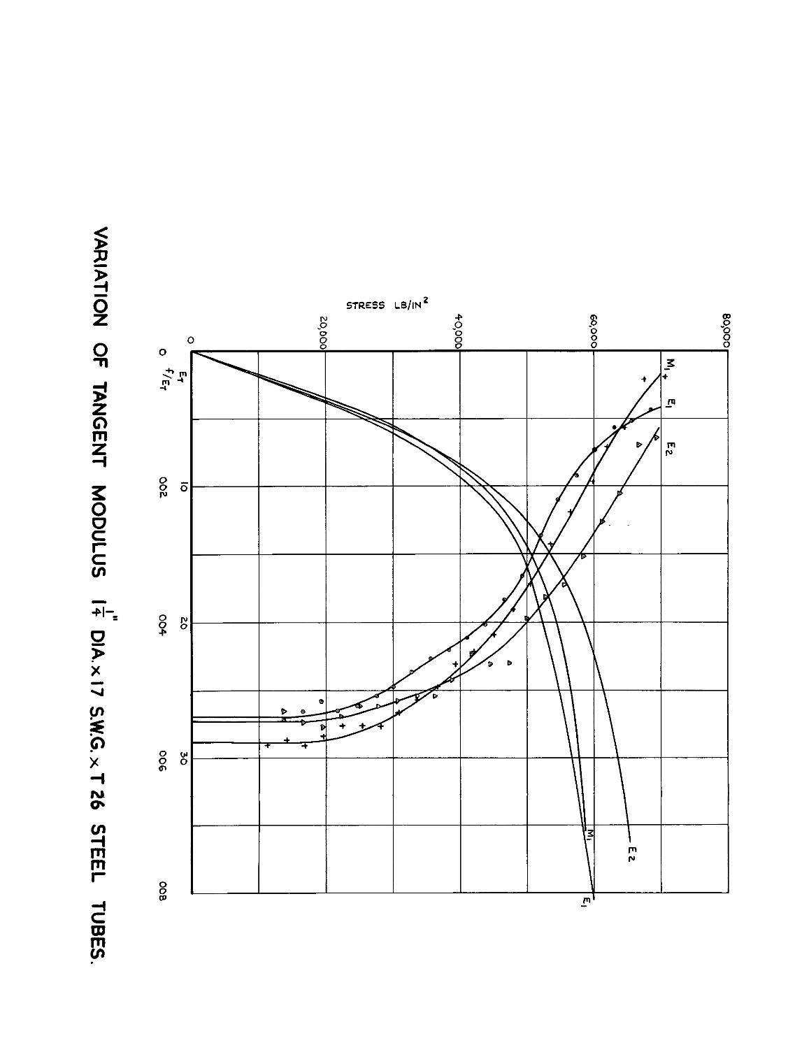
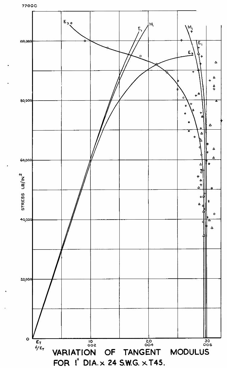
60,OC
(u z
5
z
i!2
ti
40,ot
top
.
0 ET IO 20 30
f’ET VARIATI;; OF TAN&T MODULU; FOR I” DIA. x 24 S.W.G. xT45.
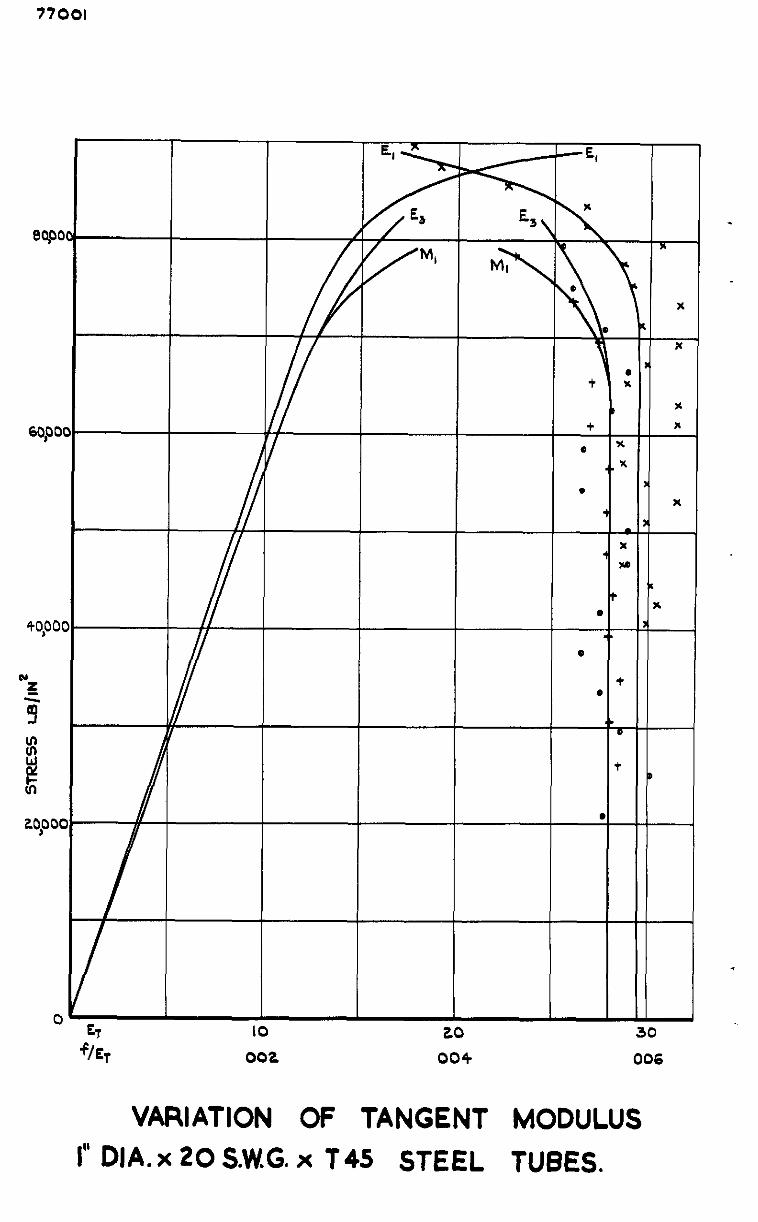
77001
I I I
3 IO 20
f/q 002 004
+
a x . . x
.
t .
x Y
t .
e
+ .
b 0
t
.
VARIATION OF TANGENT MODULUS
I” DIA. x 20 S.W.G. x T45 STEEL TUBES.
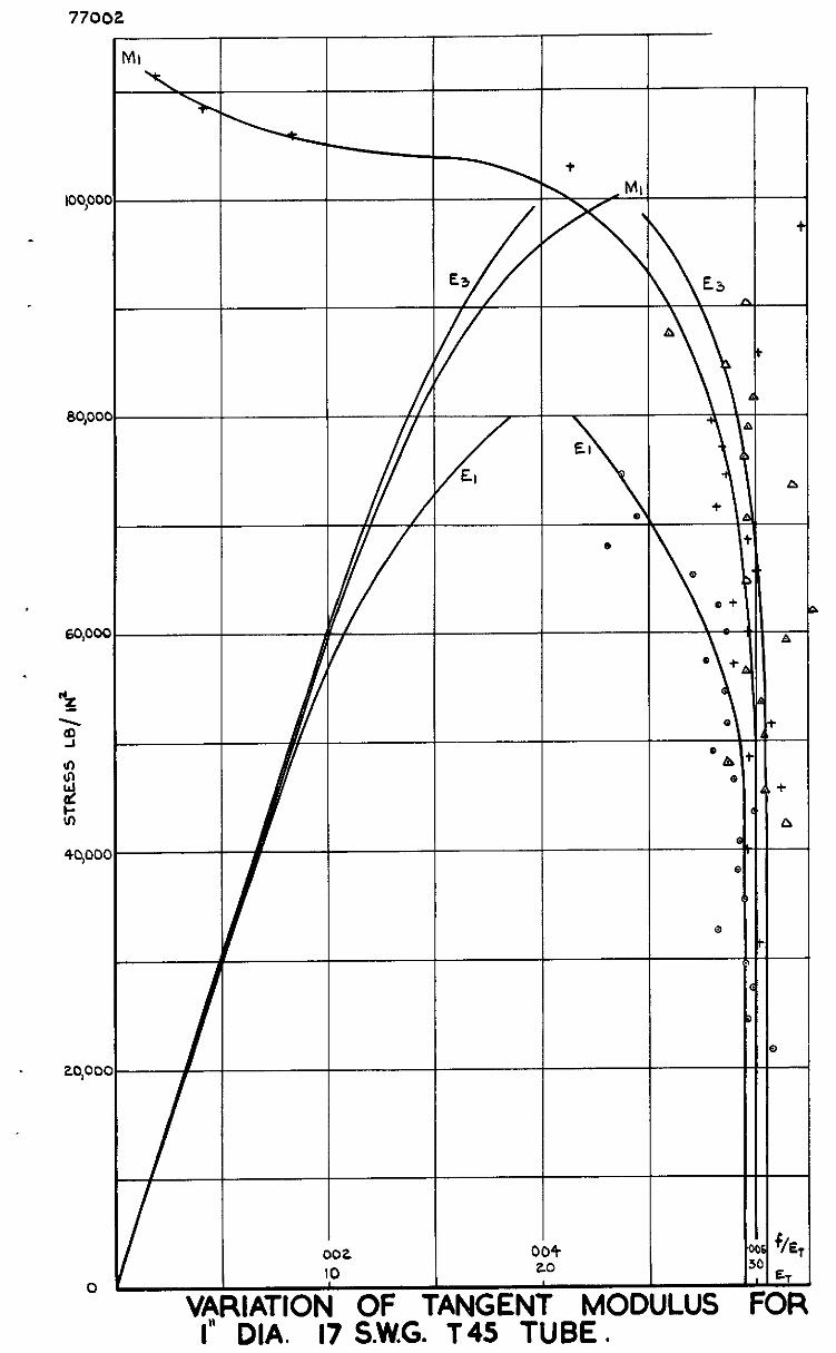
77002
I I I
loo,oo
sqoc
+ M
7
El
\ .
c
T
I” DIA. 17 S.W.G. T45 TUBE .


The tangent module mre detemmed inathematically from the 'five point' formula for numerical dxfferentlarion derived by Bickley26.
. For any five points y0, y,, y2, yj, yk, t:he mth differential of y
(m = I, 2, 3, 4) at tl~c pomt x = ra (I- = 0, 1, 2, 5, 4) 1s given by the f orrml a: -
,$ y(4 = 2 (%yo + $Y, + $y2 + A3y3 + A4y4’ (1)
3b: the case WI&ST ~~ns~aer~A,?~lon. y. . . . y4 represent extensometer scale readmgs recorded during the tensile tests, and the frost differentltil only was reqnsed at the poxnt x = 2a, whore ra' zs the load mcrement. After mbstltuting the appropriate values of Ps . . . A4 for these oontitions, equation (1) abo-re redums to:-
Y = &- (2Yo - 16Y, + 16Y3 - 2Y4) (2)
Eqm.tion (2) was a&led at successive steps of one load increment, the slope bemg deier.mn:d at the centre of the five points consuiered ir. each case. In th,; cantext the formula determnes therate of change of extcnsm.eter readmg WLth load. TO obta;n the iangont modulus the
1 recqrocd of' ths resdt 1s multlplxed by the factor
Area of specmens x extemometer constant.
Details of the load-exte.~smn readmgs are m Ap~endzx I.
- i46-

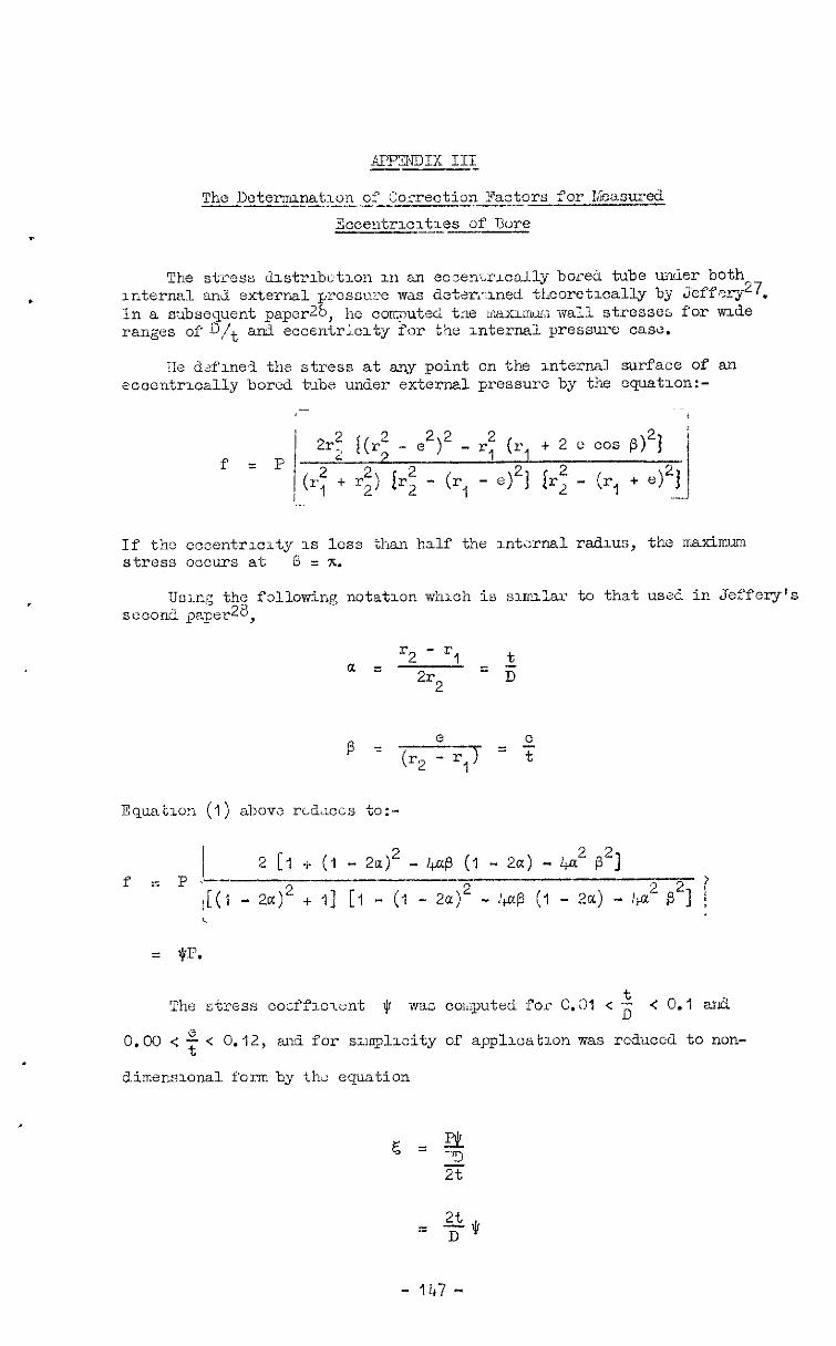
44??FmDIx III --_1--
IIe &flne* the stress at any point on the ulterml surface of an eccentrically bored tube under external pressure by the cqmtlon:-
-- /
f =P i 2r; Q - ,2)2 _ rf cr, + 2 e cos ~)~f '
+ r;, ir; - (r, - e)2j {r: - (r, +
If the eccentrmxty 1s loss than half the mtanal radms, the maximum stress occurs at e = 7c.
TJ,~.ng the following notatmn whxh i a smnlar to that use?. in Jeffery's secod paper=,
'2 - rl t a =
2r2 = 5
J3quat1on (I) abow rLdilCis to:-
/ f = P L-
2 [I + (1 - 2t$ - I+o$ (1 - 2a) - 4a2 P2] --
\[(I - 2a)2 + I] [I - (I - 2~6)~ - :+a3 (I - 2aj - k-a2 p2] i
= $P.
The stress cocffxxent $ waci coI,!puted for 0.01 < i < 0.1 arid
0.00 < : < 0.12, and for smplxity of applrcatlon was redilccd to non-
dimemlonal fom by thi: equation
- 1147 -
The values of c and $ for tlw r,age of $ and ; covered by the
aomgatation are shown in tabular form xn 'able XVIII and the variation of is presented graphically in Fig.9.
Corrections for eoccntrlclty effects were made by multipLyzag the value
f of - calculated by Stwm and O'flnen's method by the non-dunensional Et
aoeffxient 5, determined for the measured eccentrloltle.3 of each specimen The factored tangent modulus was then read directly from the ap>ropriate
stress-tangent rnod.ulus - 6 curve. t
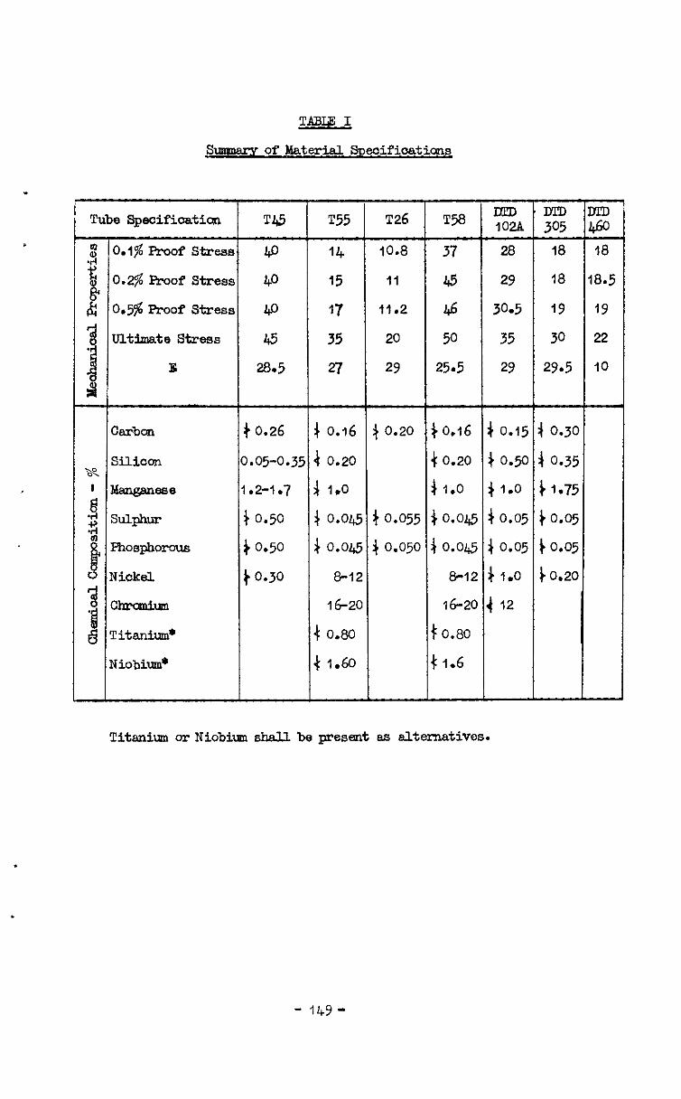
2AEhu Ehnwem of Material Svecificatione
Tube SpcifScatia U5 T55 T26 T% !$$, $f MD 460
2 O.l$ Proof stress lf.0 14 10.8 37 28 18 18
g 0.2$ Proof Stress 40 15 11 45 29 18 18.5
i 0.596Proof Stress 40 17 11.2 46 30.5 19 19
3 ultlaate stress 45 35 20 50 35 30 22
-!I E 28.5 27 29 25.5 29 29.5 10
A
) 0.26 4 0.16 $ 0.20 )0.16 4 0.15 4 0.30
0.05-0.35 a 0.20 + 0.20 ) 0.50 4 0.35
1.2-1.7 j 1.0 + 1.0 + I.0 il.75
+ 0.50 4 0.04.5 + 0.055 /o.ol& 4 0.05 )0.05
iO.50 ) 0.045 4 0.050 $0.04.5 4 0.05 io.05
to.30 8-12 e-12 # 1.0 io.20
4 0.80 16-20 to.80 16-20 4 12
Niobium* 4 1.60 t 1.6
Titanic or Niobim ehdl be present es alternatives.
- ILY-
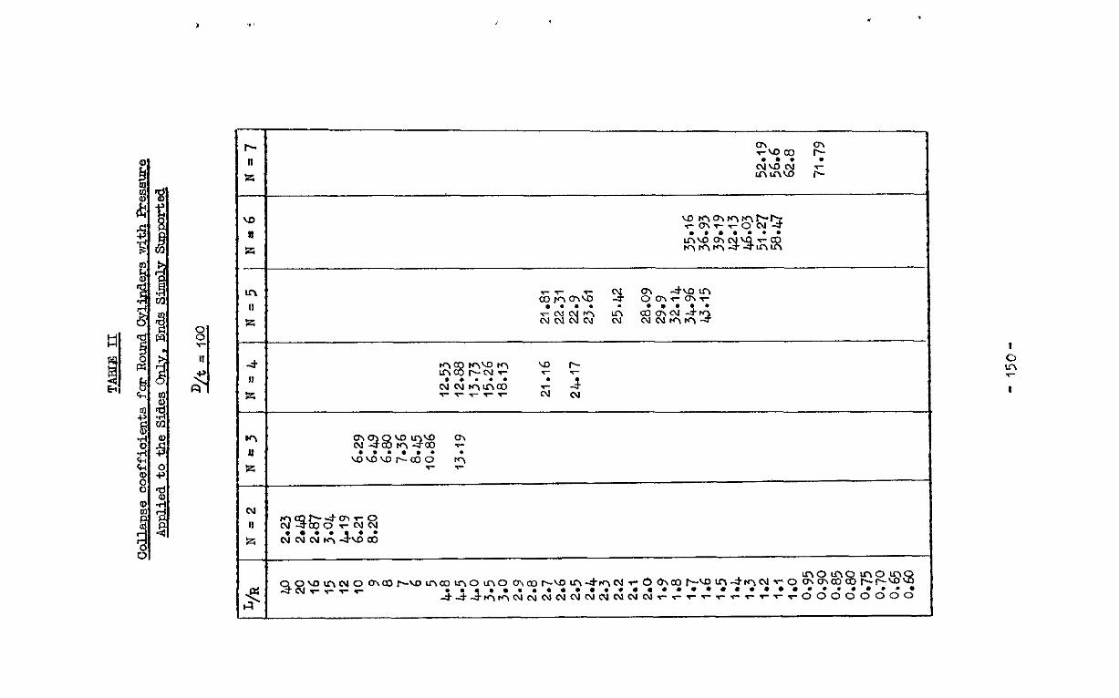
, x
h
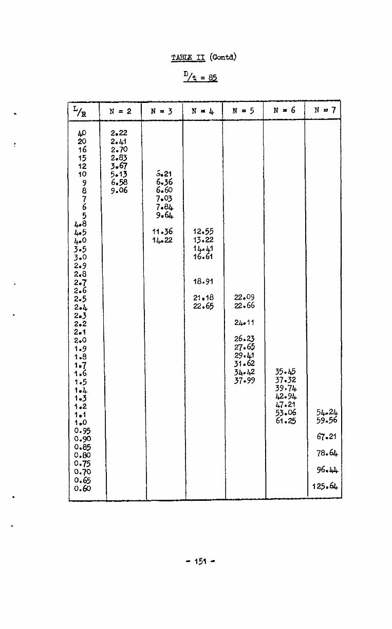
TABLE If (conta)
c
.
CT-- w, 20 16 15 12 IO
i
2 5
2
:; 3.0 2.9 2.8
2: 2.5 2*4 2.3 2.2 2.1 2.0 1.9 1.8 1.7 1.6 1.5 1.4 1.3 1.2 181
A:$ 0.9 0.85
FL; 0.70 0.65 0.60
N =2
2.22 2.41 2.70 2.83
9.06
N=3
5.21 6.36
76:: 79% .
11.36 14.22 12.55
13.22 14 1 16. I 2
18.91
21.18 22.09 22.65 22.66
Z&All
26.23
g;: 31:62 34-42 37.99
~=6
35.45 37.32
Z'E 47121
$I;2 61.21
78.64
96.~~
125.64
- 151 -
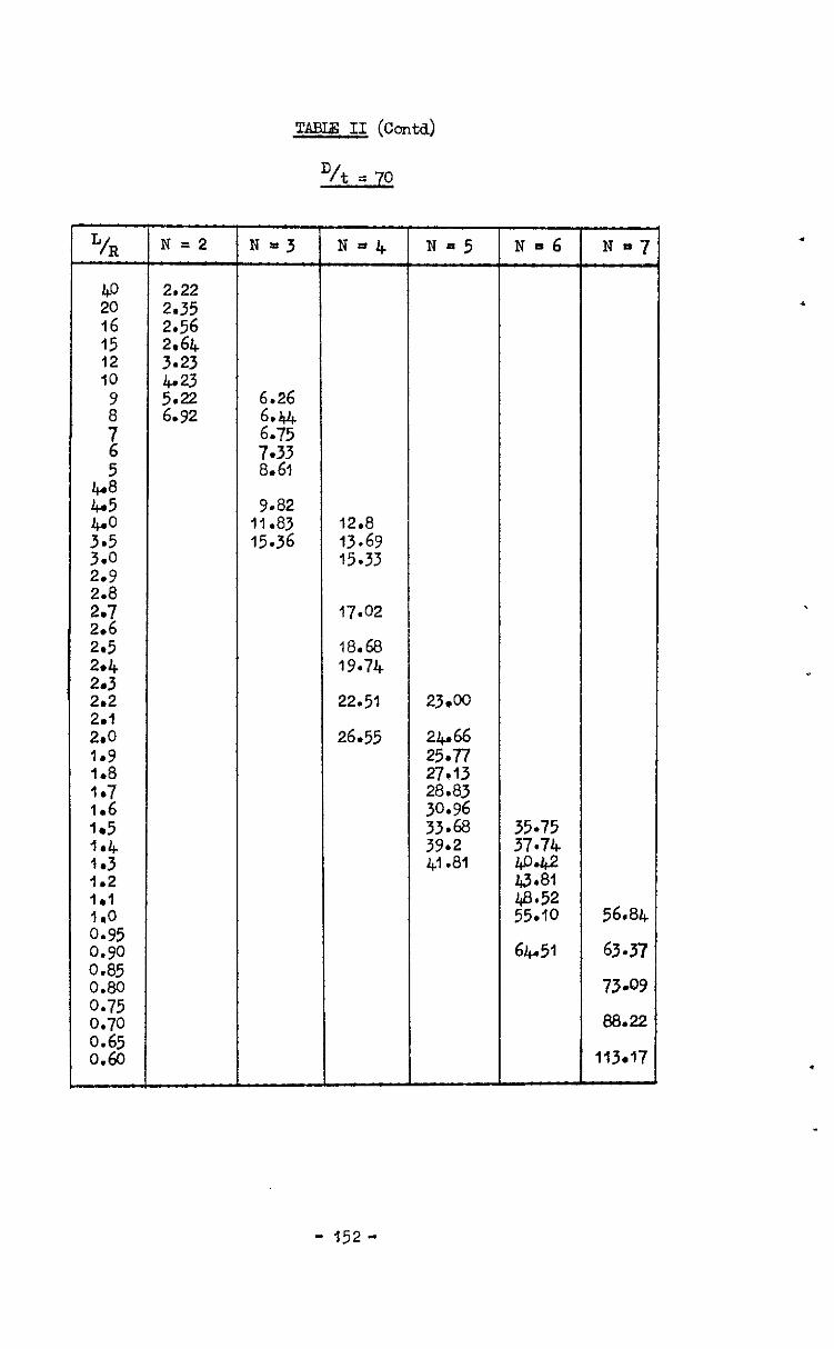
TAExd3 II (cc&d)
D/t 5 70
2.5s 2.64 3.23 4.23
'6% .
2.5 2rL 1
18.68 19.71
2~3 292 I 2.1 2.0 1.9 1.8 I.7 1.6
"& N = 2 N=J N*4 Na5 N-6
40 2.22 20 2.35
6.26
9.82 11.83 15.36
12.8 13.69 15.33
17.02
22.51 23.00
26.55 24.66 25.77 27.13 28.83 30.96
'5 I.5 I I I 33.68 IaL 39.2 E4 I 1.j 1.2 1.1
A:;5 0.90 0.85
::; I 0.70 0.65 0.60
il.81 g% 48.52 55.10 56.84
63.37 64&l 64&l
73.09 73.09
88.22 88.22
113.17 113.17
- 152-
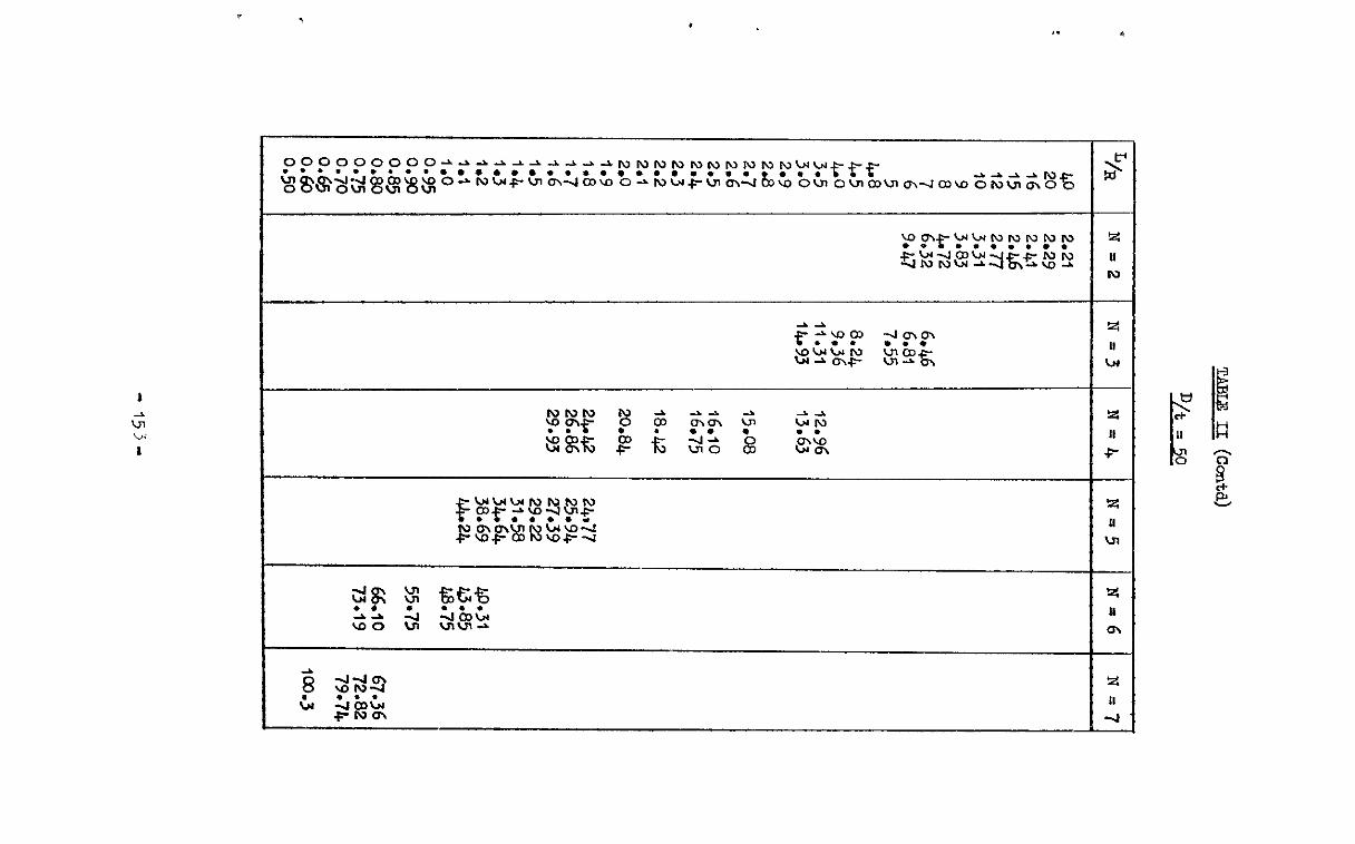
r
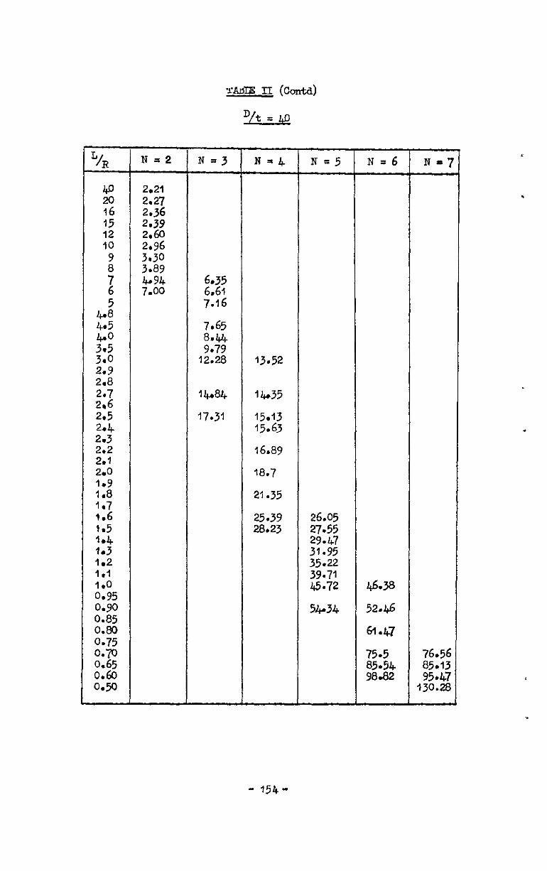
@ 20 16 15 12 IO
i
z
6 .
is 3aO 299 2*8 2.7 2.6 2r5
22:: 2.2 2*1 2.0
28’ 1.7 1.6 ta5
2,” 182 1 .I 1.0 0.95 0.9 0.85 0.80 0.75 O.-D 0.65 0.60 0.50
N=2 2.21 2.27 2.36
‘2% 2:96
N=3
6.35 6.61 7.16
7.65
98% 12.28
14~84
17.31
13.52
lb35
15.13 15.63
16.89
18.7
21.35
25.39 2&23
N=5 N=6 Nmj
26.05 27.55 29.47 3r.95 35.22 39.71 45.72
5Lr34
46.38
52.46
6142
75.5 85.54 98.82
76.56 85.13 95.47
130.28
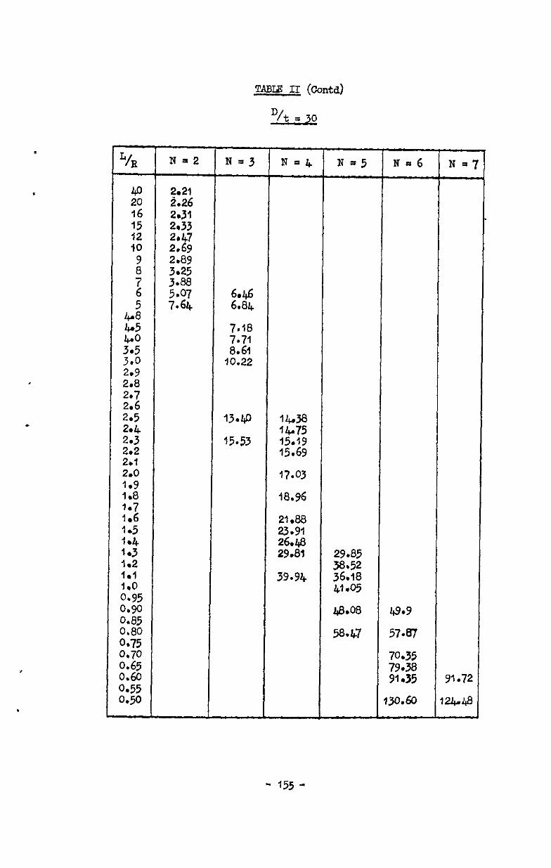
TABI3 11 (Contd)
vt = 30
,
Lh Na2 N=3 N=4 N=5 N=6 7
N =’
40 2*21 20 2.26 16 249 15 2~33 12 IO 22: 2 ; s9 3.25 2.89
2 3.88 5.07
5 7.64 66:g
t; 7.18 4.+0 ::50 10:22 ;(*z
2.9 2.8
22 2.5 13.40 lb,38 2*4 14.75 2: 15.53 15.19
15.69 2rt 2.0 17.03 1.9 1.8 18.96
::76 21.88 1.5 23.91 1*4 2643 I.3 29.81 29.85 I.2 38.52 181 36.18 ::;5
39.94 41.05
0.9 0.85 0.80 0*75 0.70 0.65 2;
0.9
40.08 49.9
57.61 588.47
70.35
;:*g . 91.72
130.60 I&48
- 155 -

Lhl N=2 N=3 N=l+ N=5 N=6 N-7
40 2.21 20
% 16 . 15 2.29 f2 2.36 IO
i 2 2.79 7 3.11
r6 3.71 4.95
2
22 3.0 2-9 2.8 2.7 2.6 295 2.L 2.j 2.2 2.1 I 2.0 1.9 1.8
2 1:5 I*4 1.3 la2
6.85 7.2
2::
10.62
11.85 12.63
14.66 15.98 17.57
0.90 43-6 0.85
i:E 025
52.4 66.34
0.60 w.u, 66.00 89.04 0.55 102.02 0.50 122.78 120.33
- 156-
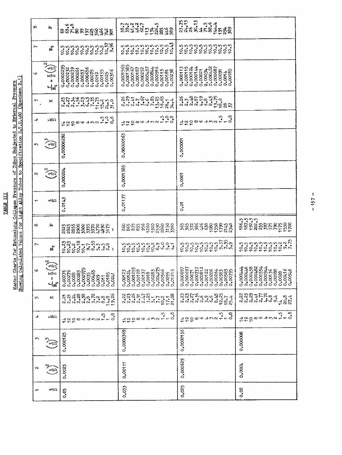
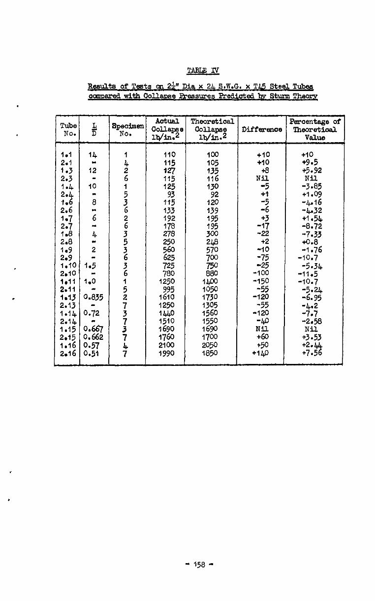
.
TABUIV
Result8 of Tests on 29' Dia x 21 S.W.G. x T&.Lj Steel Tubes oaroared with Oollame Freasures Prediotd by Sturm Theoq
Tube & Actual Theoretioal sF+oimm aouape
Percentage oi No. D NO. Idin.
Collapse Is/in.2
Differm~e !Qwomtioal V&W
I.1 ::: 2.3 1.4 2. 2 26 2jJ 218
1.10 2.10 lrll 2.11 1.13 2.13 I.14 2.14 1.15 2el5
14 112
1 2
m 6
10 m : a 3 "6 6
2 4 3
; - i
1.5 3 6
1.0 :
0.835 ; 0.72 027 3 :
0.662 7
0.57 0.51 4
110 115 a7 115 125 93
115 133 192 178 278 250
zig 725 780
3250 995
1610 1250 1Ul.o 1510 $690 1760 2100 1990
100 +10 405 +10 135 +a 116 Nil
130 92 :: 120 139 1; 195 +3 195 -17 300 -22
% +2
-10 7$ -25 -75
a80 -100 1490 -150 109 -55
:;z; -120 -55 1560 -120 1550 -60 16gO Nil 1700 +60 2050 +50 1850 +I@
+10 +9.5 +5.92
-$5 +1.og -4.16 -4.32 +I .5k -8.72
E3 -1176
-10.7 -5*34
-11.5 -10.7
-5.24 -6.95
19; -2158
- 158 -
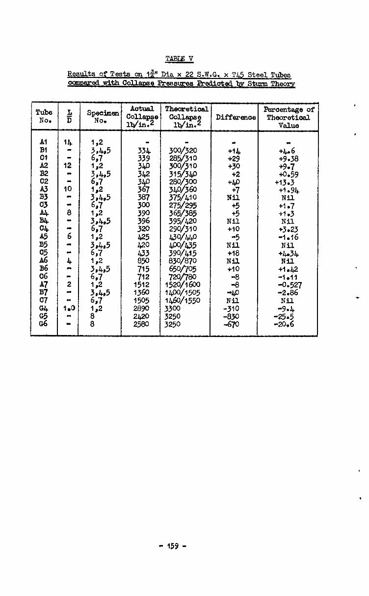
TABLZ V
Results of Tests on lp Dia x 22 S.W.G. x Tl,!j Steel T&es ; edwithco
1 I tud 1 Theoretiosl Peroentage of
'e Differenoe Theoretioal
Al Bi
z B2 02
s
2
% A5 35
2 B6 06 A7 B7
2
2 8
1512 13a 1505 2890 :$z
275/295
29v3.10
65w705 72%80
1520/l 600 14wl505 1 Gw550 3300 3250 3250
- +r4 +29 +30
+2 +40 +7
Nil +5 +5
Nil +10 -5
Nil +I8 Nil. +10
z -Ip
-;it -830 -670
+6.6 +9.38 +9.7 +0*59
+13.3 +I a94 Nil
+i .7 +1.3 Nil
+3.23 -1.16 Nil
+Ir34 Nil
+1 d+2 -1.11 -0.527 -2.86 Nil
-9.4 -25.5 -20.6
- 159 -
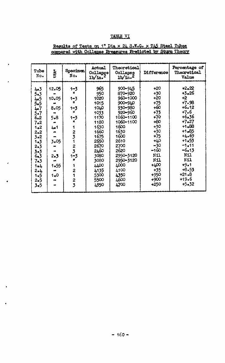
TAEU VI
Results of Tests on 1" Dia x 2L S.W.GD x TA5 Steel Tubes oaaoeredwithCollmae Breaures Prediotedk~St~~~Th~
L Ii
l2rO5
IO.05 -
8.05
5.8
3.05 m
2*3
1155 -
I.0
3geoime NO.
I-3
iI3 "
'i3
l-3 II I
: 1 2
13,J * I 2
: 3
oolla t F! la/in.
965 950
1020 1015 IOqo 1033 1170 1180
2% 1675 2650 2670
3080 3080 4400 4135 5300 5w 4950
!Cheoreti.d collapse
la/in.2
go+945 870-920 9604cno
3
:z::$ 1600 ;62
2610 2700 2620 295+3120 2950-3120
g
Diff*w0
+20 +30 t20 +75 ta t73 t7Q tea +30 +30 +75
I$ -160 Nil Nil
+400 +35
+950 +w t250
peroentags of Theomtioal
V&l8
t2.22 +3.26 t2 t7.98 t6.12 +7.6 t6.36 t7.27 Cl .a8 tie85 t4.69 +I .53 -1.11 -6.13 Nil Nil
tg.l t8.53
t21.8 +I%6
t5.32
- 160-
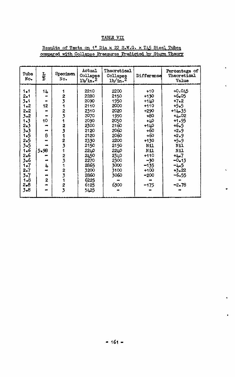
TAEUAE VII
Results of Tests on 1' Dia x 22 S.W.G. x T&5 Steel Tube4 camare3withColla~seRvasures PrdiotsdbvStumThso~
Tube % No.
Adxal. Theorstiod a+=i-n Col.l.apse
Peroentsge of
NO. Collapse Differsma Theoretiosl
lb/in.2 lb/in.2 ValUe
I*1 14 2210 2200 *lo +0.0*
::: - 3 : 2280 2090 2150 1950 +1jo +I@ +6.05 +7b2 1.2 12 I 2110 2oal +110 *5*5
::; - : 2310 2070 2020 1990 +2!xJ +a0 +16.35 +&eo2 2: IO - I 2090 2050 +bo +1.95
i: 23w 2160 +I@ +6.5
:'; . ;;
: 3
2120 2120 2060 2060 40 +60 +2.9 +2.9
::; 1 ~~ 22.00 2150 +130 +5.9 Nil 1.6 5.98 1 i:i .
2269 2249 ii:: Nil - 4 : 2450 2270 2865 gt: -135 +110 -Jo -0.13 -4.5 +4.7
::77 1.8 ;
3 : ;:z 5% 3060 -200 +I00 +3.22 -6.55 1 6225 L
: 6125 5425 63;O - -175 -2.78
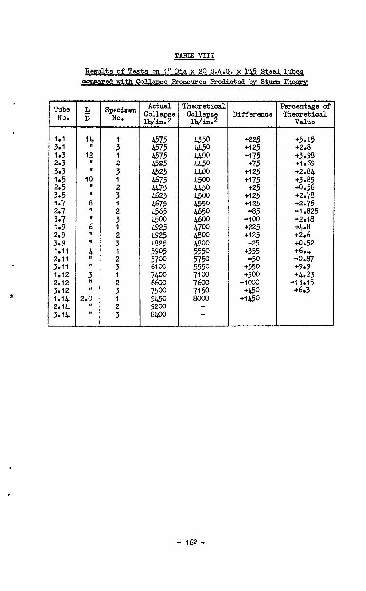
.
Tube NO.
:::
1 l 3
:::
1.5
:::
1.7
::;
2,’
3.9 1.11 2.11 3.11 I*12 2.12 3~12 1.14 2.14 3.14
TABI. VIII
Restits of Tests on 1" Dia x 20 S.W.G. x Tfi Steel Tubq aomusred with CollaDse Fressures Predicted bv Stunn Theo=
:
:
3 1
Jz I
: 1
3"
; 3 1
: 1
:
( I
Diffexeoloe
+m +I25 +175 +75
+I 25 +175 +25
+I25 +I25 -85
-100 +225 +125 +25
+355 -50
+550 +3m
-loo0 +450
+1@0
Percentage of Thmretioal
Vslue
+5a15 +2.8 +3.98 +I.69 +2.84 +3.89 tO.56 +2.78 +2*75 -1.825 -2.18 +4-a +2.6 +0,52 +6.4 -0.81 +9*9 +4.23
-13.15 +6.3
- 162 -
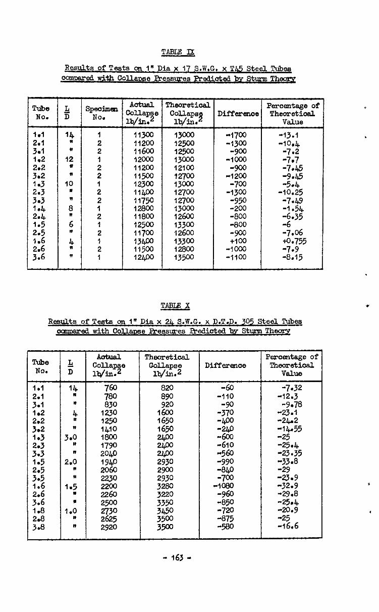
Results oPTeats on I" Dia x 17 S.W.G. x TJ& Steel Tubs~ O~L=='dwithCdla~$e PresswesPredictsdby SturmThcxxg
Tube 2 Aatual Thsoretioal sTya Cdlape
Percentage of No. D
lb/in* i! Collapsj Diffsrenoe Theoretical
lb/ill. value
2: 14 Ia 2 I 11300 11200 1m -1700 -13.1 ~2500 -1300
116co -10.4
3.1 * 2 12500 -900 -7.2 1.2 12 12ooo l3W -1coo -7.7
::," I) " ; 2 11200 11500 121co 12700 4200 -900 2% 2: IO l : 12300 IIW 73m 12700 -1300 -700 -10.25 -514
3.3 2 11750 12700 -950 -7.49
::",
ii I IS00 13000 -xx, -I*54
;
2 11800 12600 -800
;:; l z "
1 2 11700 12500 : I 12400 ::$i
13300 12600 13300 -800 -900 +I00 Ii.35 -7.06 +0.755 g::
I
13500 12800 -1000 -1100 -8.15 -7.9
TABLE X
RemiLts of Tests on I" Dia x 2& S.W.G. x D.T.D. 305 Steel Tubes occmsredtith Callawe Pressures Rvdiotsdby StunnTheoq
Tube & Thsoretiosl Peroentage of
No. D collapse Theorstioal lViIl.2
Collapse DifYPar~O6 lb/in.2 V&B
1 l l 14 -60 -732
::: II
z
ifg :; 920 -110
2;
-12.3 -9.78
::: 1230 1250 1650 1600 -23.1 -2&Z 3-2
2:
3.1; 1410 1650 -14.55
1800 1790 up0
1%
" -610 -25 -25.4
:*: " ~0~ -23.35
. 2.0 1940 E $2 3 It " 2060 2230 2930 2900 -W -700 ~~;9.8
1.6 1.5 2200 -1080 :g;
::i ” ’ 2260 :z 3350 -850 -960 -29:8 -25.4 1.8 1.0 -720 -20.9 ::: I ” 2920 if! :% 3509 zg -25 -16.6
.
- 163 -
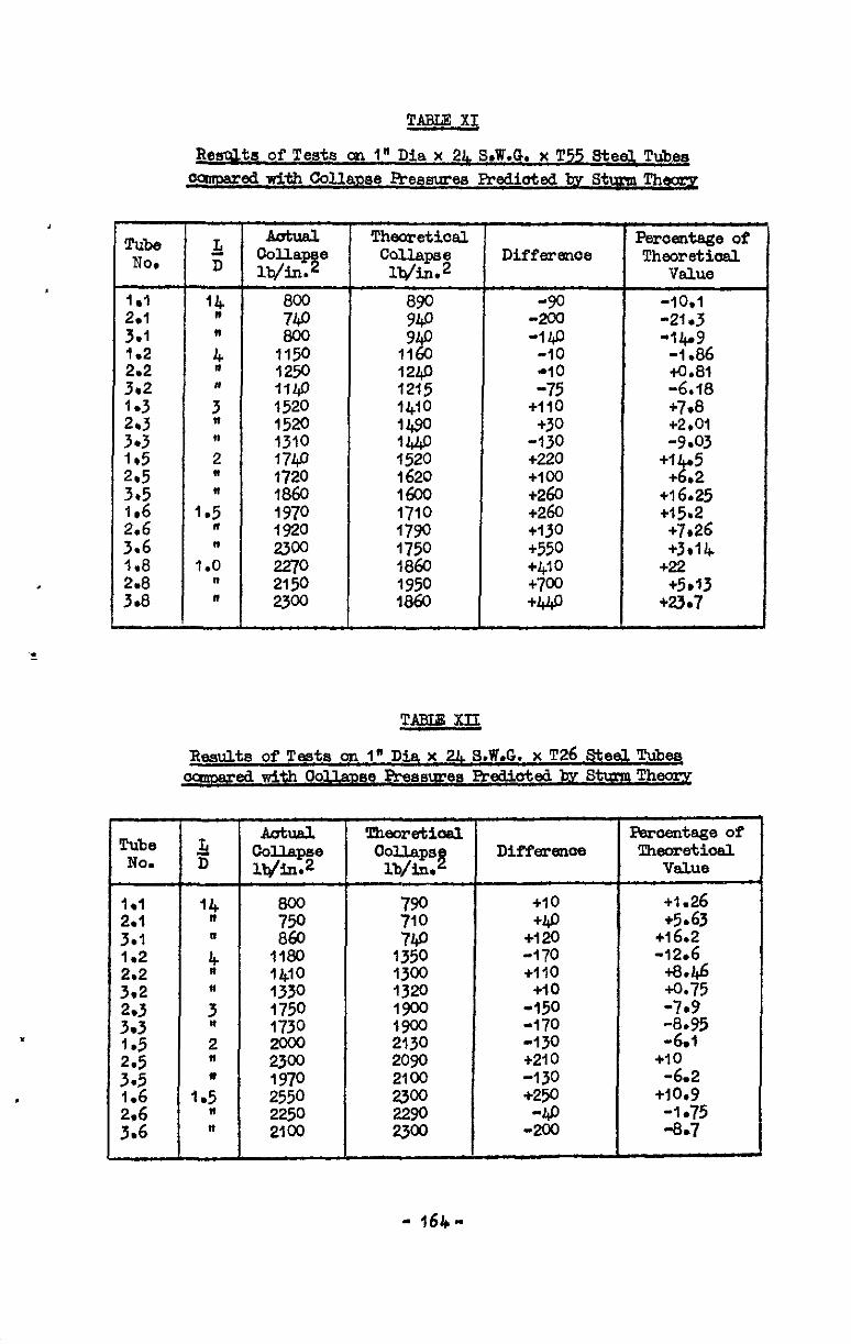
TABLE XI
Resplts of Tests 091 1" Dia x 2L S6W.G. x T55 Steel Tubeq ooIm.ared with colla3xe Awssums Preaiotted by stum Thsoqg
Tube No.
Anhal Colla 6
?! lb/in.
is 800
1150 1250 1140 1520 152o 1310 174a 1720 1860 1970 1920
l-g 2Joo
Theoretical Psro6ntsge of Difference Theoretiosl Collapse
lb/in.2 Value
89 %
--:: -10.1 -21.3 -140 -14.9
1160 -10 -1.86 1241) -10 4.81 1215 -75 -6.18 1410 +110 +7.8 1490 +3o +2*01 1440 -130 -9.03 1520 +220 1620 +100
+I 2 5 + 02
1600 +26o +16.25 1710 +260 +15.2 1790 +130 +7.26 1750 +55o +3*14 1860 +410 +22 1950 +7oo +5rlJ 1860 +440 +23*7
TABLE XII
Raslults of T&s on 1" Dia x 21 S.W.G. x ~26 Steel Ttibee ~ed~thoO~Dse~ssu~es ATeaiotedby S~Th~
Aatual Coll.apse ll4h.ll.2
F!ii 1180 14lo 1330 1750
22
:g 2550 2250 2100
!rheJn.etioal oolhps~
lb/in.
790 ii0 740
1350 1300 1520 1900 1900 2130 2090 2100 2300
DiffarsllOe
+10 +49
t120 -170 +110 +io
-150 -170 -130 t210 -130 +w
--g
!&3roentage of Theoretioal
value
+1.26 t5.63
ti6.2 -12.6
+8*46 +0.75 -7.9 $;5
+,o' -6.2
t10.9 -1.75 -8.7
- 164-
Tmlz3 XIII
Results of Tests on I" Dia x 21S.W.G. x D.T.D. 102A Steel Tubes oamarsd with Collavse Pressures Prsdiotd by Stmn The-,
Tube & Thaoretioal Perof3rdage of Nor D Collapse Differwoe Thsoretioal
lb/in.2 Cdlaaps$
lb/in. value
I*1 14 g 860 -90 -IO.!&
::: R z IE
830 900 -110 -100 -13.25 -11.1 102 1550 -210 -13r55 2*ze
:% 156a -260 -16.7
3a2 5 1700 -325 -19.1 1.3 1860 2140 -280 -13.1 3':; * % 2350 219 -280 -qso -II*9 -22.8
::: 2 - % 2420 -50 +20 4.83 -2.04 3.5 " 23N -19 -5.9 1.6 3.5 y:i . 1.0 11 " m!&
2J +1.71
~~ 2750 2640 2900 +175 -‘$
+I40 l +6.05 .52 +5.1
II
::8” ” :z 2900 Nil Nil 2950 +I50 t5.08
0.8 2'9 " 2% :ig
+w t2.95 -100
3eY to 3175 3110 +65 2': .
TABLEXIV
Results of Tests on I* Dia x 2L S.W.G. x T50 Steel Tm ommared with Collapse Pressures FPdioted bv Sttmn ThemY
Tube 5t Aotual Theoretical Pclroentageof
No. D Doll
3" lb/h. Gollaps~ Difference Theorstioal
lb/h Value
I.1 *4 low, 1030 +10 to.97 ::: *
z
1075 1000 1010 1100 -100 +65 -9.1 +6.44
1.2 l/720 1720 Nil Nil
::i !z; :iz +355 +9
-10.7 2: 4 2780 2775 2TQ 2800 -22 -25 -0.89 +2.96
3.3 ” 2750 1.5
2.: ” 35m ;iE ;:g t;t5’ ::z 3730 3&&g 3250 3330 +120 +480 td4.8 +3.6 1.6 f.5 389 +680 t17.7 2.6 n 4600
G t6ca +15
:.,” n p72
+515 +13 . 1.0 4500 +9m t20
;:8" I)
r 4600 +1050 t22.8
" z5: 4700 +875 +18.6
-165.
.

TABIE XV
3 .W.G. Ccmm Brass Tub' ocmmaredwithCoU.a~e Pressures RxdiotedbyStuxmTh~
Tube 5 sg& NO. D Collapse
181 j4 ::: I, :g 375
::i 4.;
z?z 3.2 *
7% 3.8 2; " 870 3.3 n 800
2:: 2.8 1: *
1125 1230 :'$ . 1160 1525
tf; . 1.3 n * 2060 1680 16%
,':i 11 * 2200. 2100
1.7 1.:
;:; n $z 2520
. 0.8 2780
;:i " - 2850 2820 1.9 0.t
:z ::; " 3120 1.10 0.4 3750 2.10 n 3.10 " :zi
Theoretical Percentage of
Diffwme Theoretirnd Collapse value
303 +3o +9.9 410
;;:
+45 +5 t13.6 +I*22
+30 t6.4
;iE +55 +10.2 t20 t3.86 +35 t5.07
+120 +16 g +50 +6.67
1060 930 +195 +1-P +21 +16 1060 1250 +100 +275 t22 +9.45
1380 1550 1380
t27C +3oQ t51o
tly.6 t21.8 t32.9
::g +350 +20 +4-w t25.7
:Ez t65o +36 t630 +32*3
% +580 t29.9 4.620 t30.1
2250 2200 400 +620 tz6.7 t28.2
:%?I t800 t33.3 t630 t17.5
2530 +59o t23.3 2900 +W +29ti3 3100 +7w tzz.6 3ooo t630 t22.7
- f66-
Tube No.
r-
:::
2: 3.3
2::
:'; .
43 .
,'I2
::"8 3.8
::; 3.9
TABI. XVI
Results of Tests on I" Dia x 2?& S.W.G. x D.T.D. l&O Li&t Alloy Tubesccmpared~pithOollapsePressuresPr~ctedbyS~T~~
5! D
jpeoimen
NO.
B B
B" B A B
:: B B A
:: A B
: B B A
M.lapse Lb/in.2
280 286
g
490 850
g 1020 1050 990
1620 1580 1410 4890 1870 1980 2080 2190 2150
Theoretioel Collapse lb/in.2
275 280 273 520 520 510 SKI ii.0 820
1020 IO75 1030 1530 1510 1410 la80 1880 1790 2060 2060 1990
Differenoe
2 +7 -2
+bo -20 +I0
:g Nil
;g
+70 NF1 cl0 -10
+1go +20
+130 +160
Percentage of TheoretioeZL
Vsllle
+I.82 +2.14 +2.56 -0.38 +7.7 -3.42 +1*19 -8.47 -7.32 Nil
-l.l),Tl
;35:E +4.64
+T& -0.53
~0.6 to.98 +6.31 +8.04
Mean Collapse Pressures and StandardDeviations ofExperimental Results exmessed as Percentage of snd Percentage Variations from
Collawe F!ressures Predicted bv Stum Theory remeotively
Tube siee and specification I
Mean Pressure
* diameter x 24 S.W.G. x TW ,p, " x 22 S.W.G. x T# I" I4 x 24 S.W.G. x Tl,..5 I" " I* as
x 22 S.W.G. x T@ x 20 S.W.G. x Tl$
1" " x 17 S.W.G. x Tl,.5 I" " x u, S.W.G. x D.T.D. 305 I" a x 24 S.W.G. x T55 1' * x 2& S.W.G. x ~26 I" ' x 24 S.W.G. x T58 I' " x 24 S.W.G. x D.T.D. 10% I" " x 24 S.W.G. x Brass I" " x 24 9.w.G. x D.T.D. 4.60
standard. Deviation
8.66$
TAEm2 Xix
?dean Collapse Fk-essures and Standard Deviations of Experimental Results ooz-rected for Eccentricity of Bore, exwessed 8s Percent
of andPerce.nta~eVeriations fbcrnCollaw3e Pressures Predictedby Stunn Theorv reweotiveky
i
Tube she end specification
@ diameter x 24 S.W.G. x TG ,$I " x 22 S.W.G. x Tl& In " x 24 S.W.G. T4.5 ," n x 22 S.W.G. TG ,,I n x 20 S.W.G. x T4.f~ ,” II x 17 S.W&. x Tl& 1” ” x 24 s.w.G. x D.T.D, 305 , 1, II x 24. S.W.G. T55 ," ,I x 24 s.w.G. ~26 1" " x 24 s.w.G. x ~58 i” ” x 24 S.W.G. x D.T.D. 10.u I" n x 24 S.W.G. Brass 1" " x 24S.W.G. D.T.D. l&C
Mean Pressure
98.3%
:;*;g ;g:95
2 W-b% 81.99f1
102.8/o 100.1% 107% 98.9%
119.8% 100.7%
standard Deviation
Q% 6.56s 6.%
:g
::z I;$
. 9.93
11.1% 9.6% 44
- 169 *

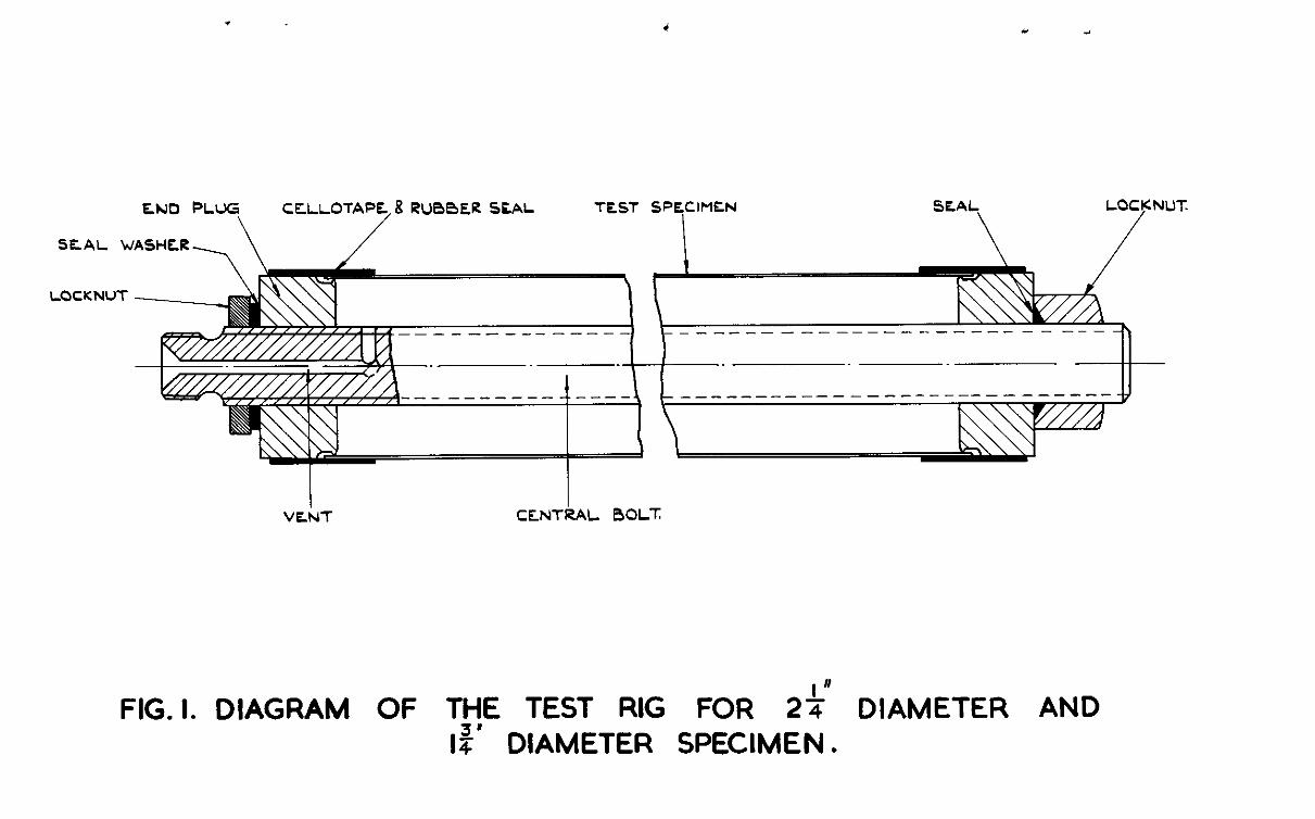
.
SEAL WASHE1R,
CELLOTAPE 8 RUBBER SfAL
/
LOCKNUT
SPECIMEN SEAL
\
LOCKNUT.
/
V&T CElNTkAL BOLT
FIG. I. DIAGRAM OF THE TEST RIG FOR 2%” DIAMETER AND I:’ DIAMETER SPECIMEN.
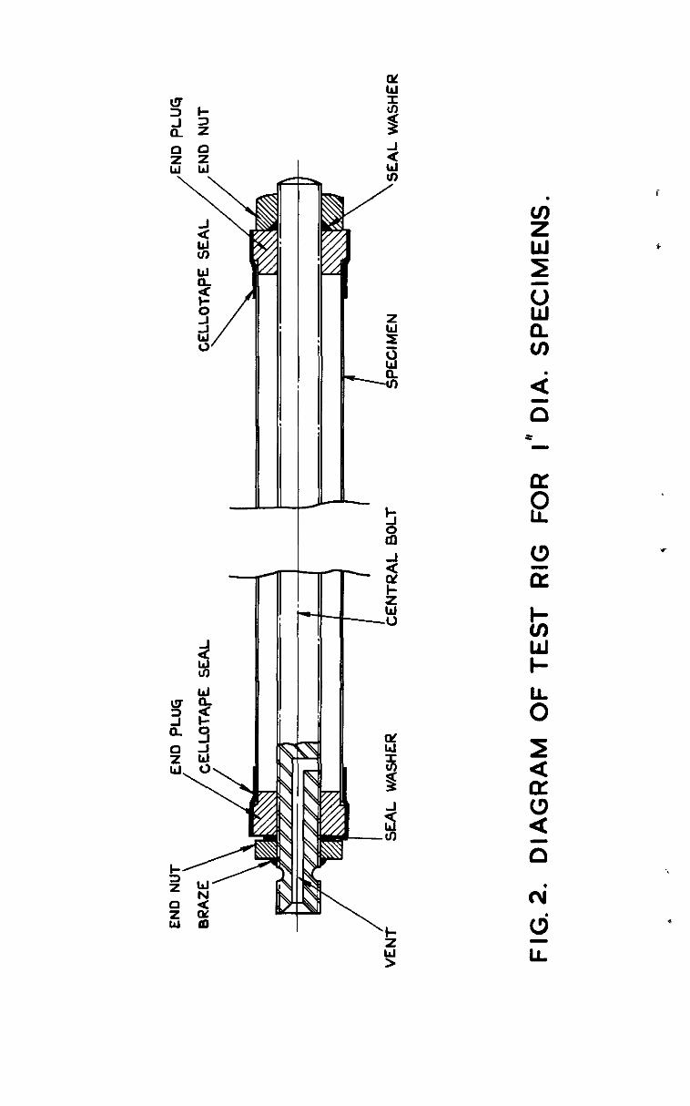
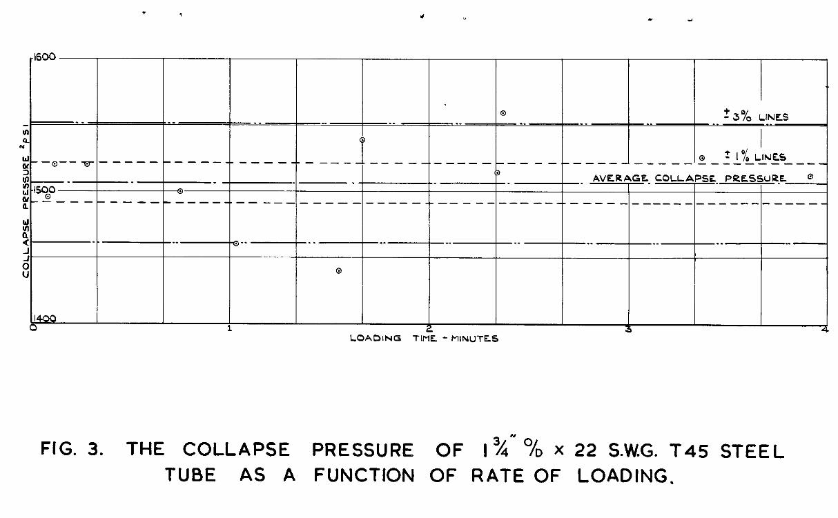
. 7 a 0 c i
1600
@ -_ 23% LINES __ . . __ __ ._ . . __ . . . .
0 I .
(3 --a-- m-------
+ 1% LINES ---- ------------ - .--- --.--------- ------- --------------- 13
-_ _ AVERAGE. COLLAPSE PRESSUR.EL 1500 -“----------m--w. ---------------
T --- ---- -------- ------_------------
._ . -_ . . -- _. __ . . __ ._ --
1400 b 1
LOADING Tlr% - MINUTE~S 3
FIG. 3. THE COLLAPSE PRESSURE OF I%” % x 22 S.W.G. T45 STEEL
TUBE AS A FUNCTION OF RATE OF LOADING.
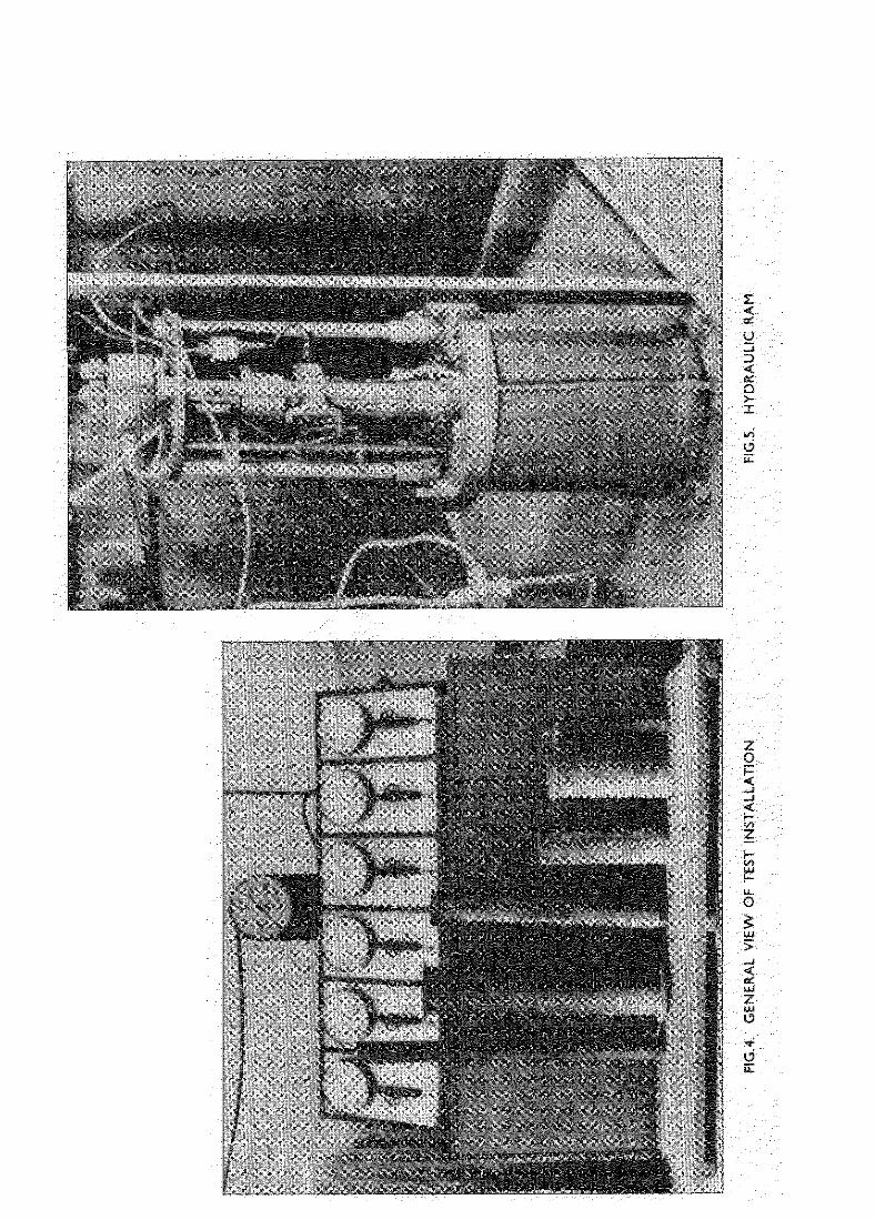
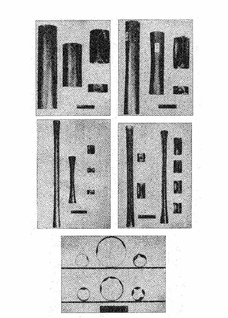
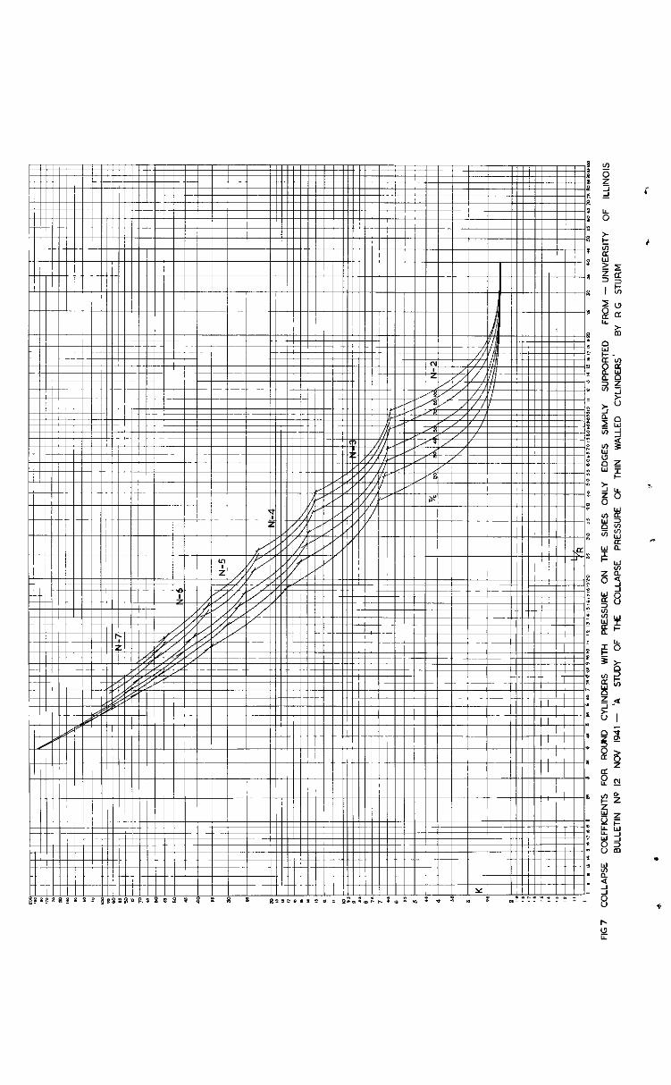
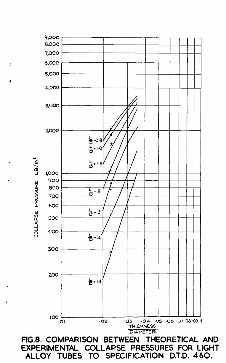
9,000 8,000
7,000
6,000
5,000
4,000
3,000
2,000
* 2 3 1,000
. 900 800
2 700
600
300
200
I I, I 1 I t I, I II I
/I /
!5;-2l /+ / I/ Y I I I I,
//.y
100 L .Ol .02 *03 .04 .05 .06 *07 08.09 *I
THICKNESS DIAMETER
FtG.8. COMPARISON BETWEEN THEORETICAL AND EXPERIMENTAL COLLAPSE PRESSURES FOR LIGHT
ALLOY TUBES TO SPECIFICATION D.T.D. 460.
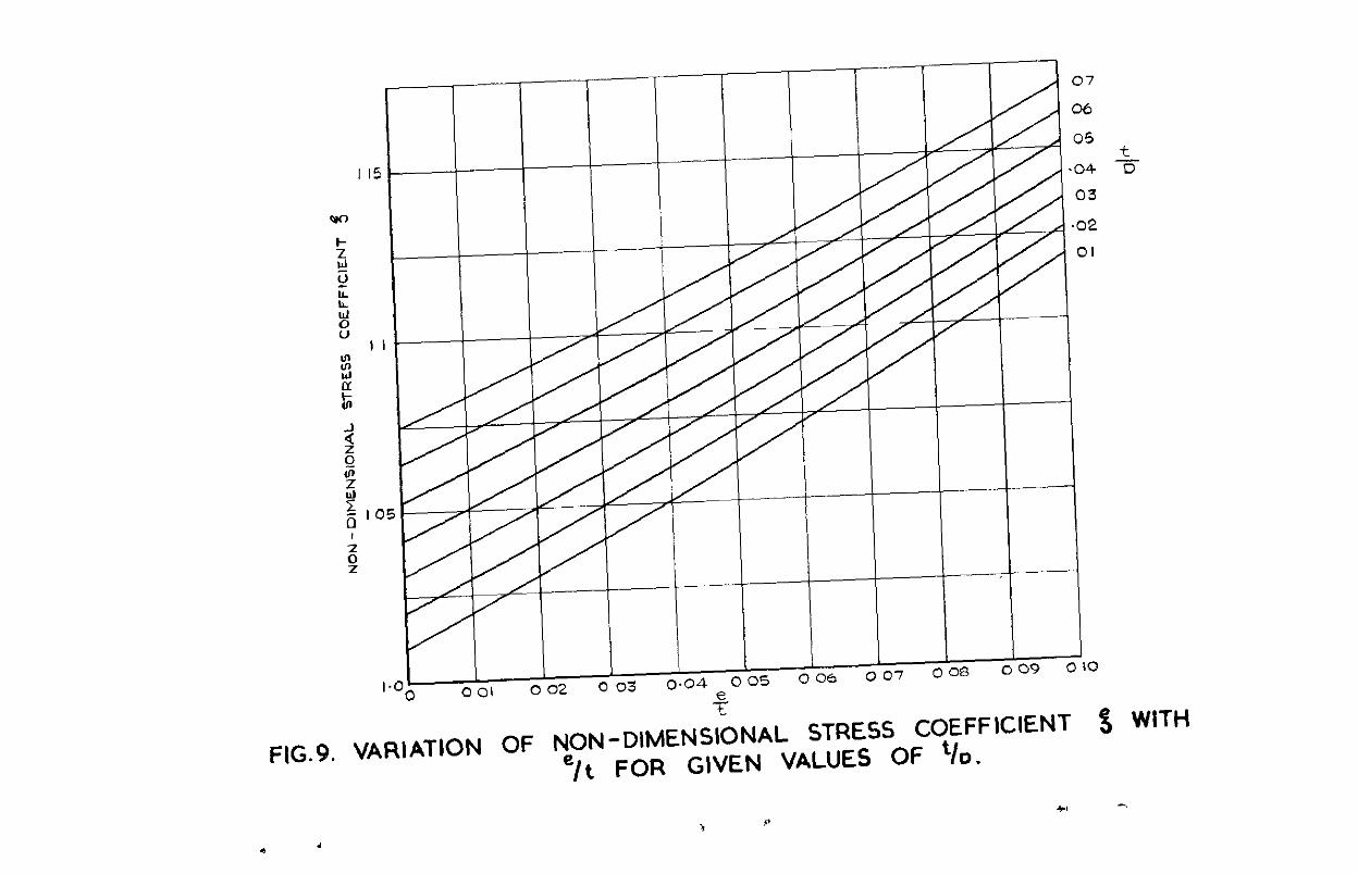
07
06
FIG.9. VARIATION OF NON- D,MENS;ONAL STRESS COEFFICIENT ‘j WITH =/t FOR GIVEN VALUES OF ‘/CL
4.1 -
> 9
* ,
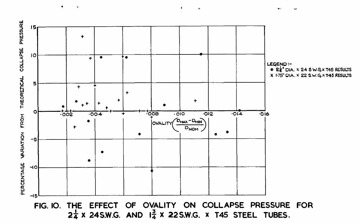
I5
IO I +a b
5
I
t
t t
t
t C -t-
14 + 0 4 2 -C 4 .C
e t
Q (P
,e w
-I- 0
-IC
-I! ! z FIG. IO. THE EFFECT OF OVALITY ON COLLAPSE PRESSURE FOR
2$ X 24S.W.G. AND I$ X 22S.W.G. x T45 STEEL TUBES.
EGEND :-
Q) 2!$” DIA. X 24 S W.~.X 145 RESULTS X k75’DIA. X 22 sW.G.XT45 RESULTS
,
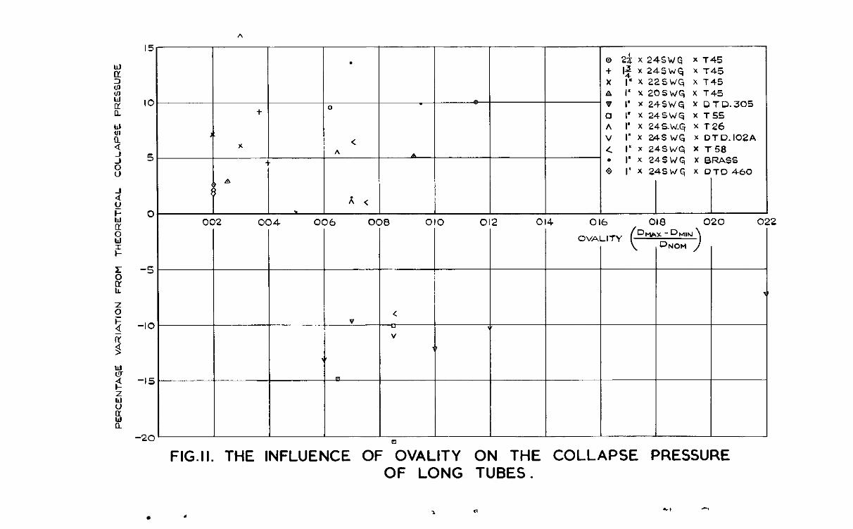
15
IO
5
0
-5
-IC
-15
-2C
.
h
.
+
* h
t I IOE 002 004 006 0
v I < I
Q 2-8 x 24SWG x T45 + I$ X 24SWG X T45 X 1” X 225WC+ x T45 A I’ Y 2OSWG, X T45 v I’ x 24SWG x DTD.305
0 I” X 245WG X T55 A I’ X 24S.W.q X T 26 ” I’ X 245 WG Y. OTD.lO2A 4 I’r24SWq XT58 . I’ x 245 WG X BFZASS 0 1’ X 24SWCi X DTD460
I 010 012 014 016 Oli3 020 <
FIG.II. THE INFLUENCE OF OVALITY ON THE OF LONG TUBES.
OVAUTY ( D*Ur
I IL
-DMIN JNOM
I COLLAPSE PRESSURE
!2
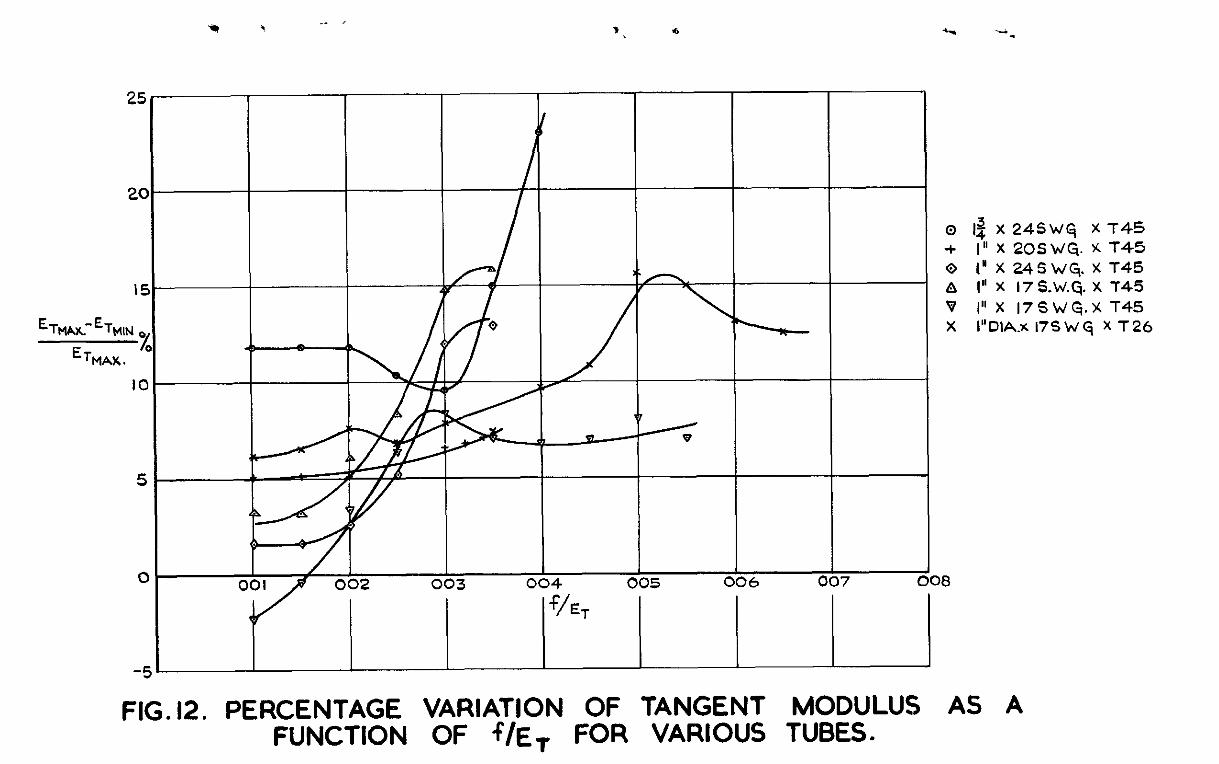
25 7
20
15.
ETw.- %4lN
ETMAX. %
IO
5
-
-
0 I / I I I I I I 1 002 003 004 005 006 007 008
f/ET
o 1% X 24SWq X 145 + I” x 2oswcj. x 145 0 IYX24SW&XT45 A I” x 17s.w.q. x 145 B I” x i7SwCj.x T45 X 1”DlA.x 175 W G, X T 26
FlG.12. PERCENTAGE VARIATION OF TANGENT MODULUS AS A FUNCTION OF f/ET FOR VARIOUS TUBES.
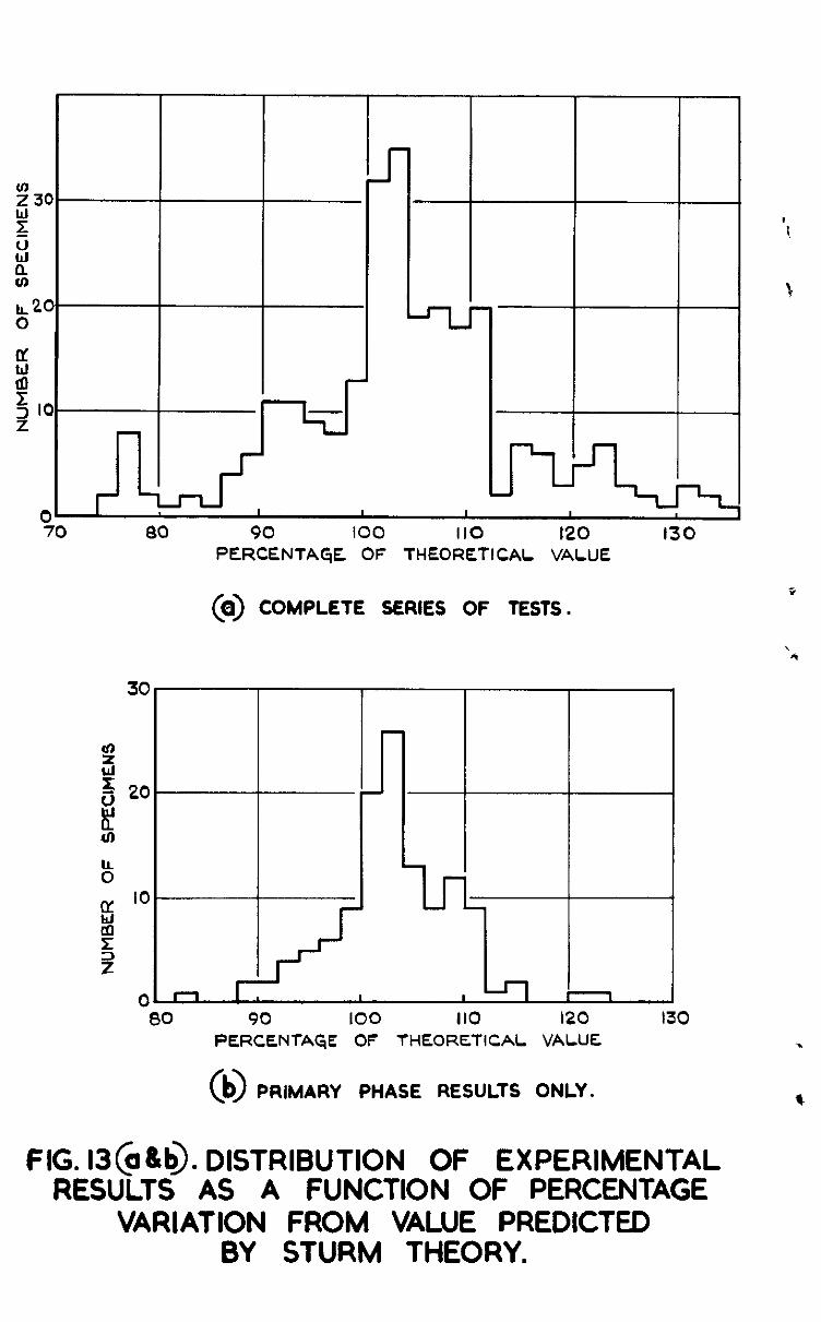
IL20 0
9 z 2 10
0 I I 70 80 90 100 110 I20 130
PERCENTAGE OF THEORETICAL VALUE
(o> COMPLETE SERIES OF TESTS. s
,
I n I . I I n
I 90 100 110 120 130 PERCENTAGE OF THEORETICAL VALUE %
09 PRIMARY PHASE RESULTS ONLY. *
FIG. 13(0&b). DISTRIBUTION OF EXPERIMENTAL RESULTS AS A FUNCTION OF PERCENTAGE
VARIATION FROM VALUE PREDICTED BY STURM THEORY.


Wt.M7&K3
C.P.N% 253 A.R.C. Technml Report
Chum copynghr resmwd
Pubbshed by HER MAJESTY’S STATIONERY OPr;IC@
To be purchased from York House, Kmgsway, London w c.z
+a3 Oxford Street, London w I P.0 Box +g, London S.B.I
‘3~ Castle Street, Edmburgh 2 109 St. Mary Street, Cardiff
39 Kmg Street, Manchester z Tower Lane. Bristol I
z Edmund Street, Bnungham 3 80 ChIchester Street, Belfast
or through any bookseller
S.O. Code No. 23-9009-53
C.P. No. 253