the stand for fin drives energy testing
TRANSCRIPT

250
Pedagogika-Pedagogy Volume93,Number6s,2021 Педагогика
THE STAND FOR FIN DRIVES ENERGY TESTING
Andrzej Grządziela1), Marcin Kluczyk1), Tomislav Batur2)
1)Polish Naval Academy (Poland)2)University of Split (Croatia)
Abstract. The development of recreational diving and the new biomimetic vehicles for civilian and military purposes indicates that fins drives' effectiveness should be a standard research procedure. The different sizes, construction and technical solutions of fin thrusters are the reason that no standard has been introduced for evaluating their efficiency. The paper presents an episode of the research carried out as part of a project financed by The National Centre for Research and Development in Poland concerning fin drives development. The first chapter presents a literature analysis of currently used research methods. A different approach to assessing efficiency was indicated, ranging from the study of the diver's respiratory efficiency to the manipulator measurement methods. The hydrodynamic parameters, which analyzed the propellers, including fins, and the fish swimming motility characteristics, were indicated. The next chapter presents the water tunnel for basic research with measuring equipment and the range of applications. The methodology for assessing the hydrodynamic and energy efficiency of fin's drives is presented in the third chapter. The fins' kinematics and dynamics analysis indicated an initial set of geometric, kinematic, and dynamic parameters for energy and functional assessment purposes. The scope of available tests covered issues complex to quantify unambiguously; hence the obtained results were initial. The form made this assessment of successive pool tests, the aim of which was to analyze the kinematics of the fin's operation. The trials of a representative fins thruster and the comments indicate the test stand’s practical use for testing various propellers.
Keywords: fins; efficiency; methodology; test stand
IntroductionRecreational diving is the more and more recognizable method of spending
leisure time actively all over the world. The industries associated with this form of activity are competing with each other more and more. One of the essential elements of a diver's equipment is the fins. Their task is to increase the diver's drive's efficiency, stabilize the position in motion, and the possibility of changing the draft with little energy effort (Bideau et al. 2003). Additionally, subjective
Marine Engineering Educationhttps://doi.org/10.53656/ped21-6s.22sta

251
The Stand for Fin Drives Energy Testing
sensations such as the comfort of movement in the water and ease of putting on or low weight also seem important. The recreational fin market is currently an area of high competition; however, the fins' choice is not determined by physical or kinematic parameters. Most often the manufacturer's brand recognition or other marketing factors such as color and even packaging play a role.
The paper presents the stand for testing recreational fins and the methodology for assessing their energy efficiency. Literature analysis confirms that many research centers in the world are also trying to find a method and algorithm to evaluate recreational fins. The paper presents exemplary research results and formulates postulates for a further upgrade of the research stand. The method of assessing the comfort of movement was also indicated which is most often treated as a subjective factor but essential when choosing the fins.
The methodology for assessing energy efficiency can be either medical or technical (Zamparo et al. 2002; Zamparo 2008) The study made at the University at Buffalo noted that the ability to swim during diving depends on a combination of neuromuscular and metabolic factors (Minak 2004; Wylegala et al. 2007). It has been shown that fin swimming is influenced by the diver's anatomy and the selection of fins in terms of the diver's speed. The research results also confirm the correct position to determine the energy efficiency of fin swimming carried out at the University of Erlangen-Nurnberg, Germany (Groth et al. 2015). Air consumption measurements and CO2 excretion were taken as energy parameters during the training sessions. It has been noticed that the diver's skills and training status can significantly affect the results obtained during the fin tests. The study made in Wroclaw University of Science and Technology, Poland, evaluated the influence of the swimming speed during diving on the biomechanical parameters describing the movement of selected measurement points of the lower limb (Wojtków et al. 2017). The conducted results presented that divers adjust their lower limbs' action to the swimming pace, which confirms personal divers' movement parameters. Thus, the medical methodology will always have a risk factor for assessing energy efficiency, such as the diversity of a diver's biology, efficiency and metabolism.
Another approach to energy efficiency assessment of the fins is to assess the physical parameters, i.e. the thrust and propulsive efficiency. The first study conducted at the University at Buffalo used a mixed method, i.e. a diver who swam “all-out” against a strain gauge. The diver swam at 1.25 m depth for 20 sec and then rested for 5 min before swimming with the next fin. The thrust values were integrated over that time to give an average maximal static thrust (Pendergast et al. 2003).
The analysis of the fin drive's mechanical parameters was the subject of Guillaume Nicolas et al (Nicolas et al. 2010). The authors present the research methodology based on the analysis of hydrodynamic and energy parameters.

252
Andrzej Grządziela, Marcin Kluczyk, Tomislav Batur
They offer a simplified model of a manipulator that simulates the movement of a diver's ankle. The fin energy efficiency is presented as the ratio of the mechanical energy value produced by the fin to the motors' energy driving the manipulator. The obtained results confirm the objective energy assessment's correctness; however, the assumed methodology ignores the diver's knee movement's influence, which is quite a simplification.
Analyzing the literature, the authors concluded that a thorough analysis of the fins' energy efficiency should meet two main postulates. First, efficiency should be measured by physical parameters related to hydromechanics. Second, a mechanical manipulator's application should consider both changes in the kinematic parameters of the ankle and the diver's knee (Grządziela et al. 2020).
Test stand – water tunnelThe test stand's conceptual design assumed the use of a water tunnel to study
fins and other biomimetic propellers with a mechanical manipulator simulating the movement of a diver's leg. An additional requirement was the tunnel's diameter, the size of which would allow divers to swim in the enclosed space of the tunnel simulating the exploration of caves, wrecks, etc. The fulfilment of both requirements caused the tunnel's dimensions and its foundation were brought beyond the laboratory conditions to the open space - see Figure 1.
Construction of the water tunnelThe water tunnel was made of composite materials used as half-pipe type water
slides in the waterparks. The facilities were built in Darzlubie, northern Poland, as part of a Polish National Center for Research and Development project. The geometry of the tunnel with the locations of the measuring devices is shown in Figure 2.
Figure 1. Photograph of the test stand – water tunnel [Authors photos]

253
The Stand for Fin Drives Energy Testing
Figure 2. The geometry of the water tunnel
The tunnel has been filled with the app—64 m3 of fresh water. The water was put in motion by a propeller powered by an electric motor with a power of 5kW – see Figure 3. The propeller drive used allows for a maximum water speed of up to 0.6 m/s, which corresponds to the diver's fast movement speed. The fin effectiveness tests performed by divers’ underwater operating speeds were adopted in the speed range from 0.2 to 0.3 m/s, conforming with diving expert opinions. Water current wanes were assembled before the test section to obtain laminar flow – see Figure 4. The laminar flow was confirmed by the optical method. The (Pitot-Static) Prantl’s tube and an ultrasonic flowmeter measured the speed of the water. The differences in the measurement results for operating speeds did not exceed 2%, which was considered a satisfactory result.
Figure 3. The propulsion system of the water tunnel [Authors’ photos]

254
Andrzej Grządziela, Marcin Kluczyk, Tomislav Batur
The problem was getting good results with the ultrasonic flowmeter for speeds above 0.4 m / s. The use of an electric motor to drive the propeller caused substantial interference for ultrasound measurements.
Figure 4. The water current wanes assembled before the test section
The manipulator simulating the diver's leg movement was placed inside the test section on a support frame with a dynamometer. The supporting frame structure
Figure 5. The support frame above the test section with the manipulator [Authors’ photos].

255
The Stand for Fin Drives Energy Testing
and the method of fixing the dynamometer ensured the measurement of the force (fin thrust) in the horizontal direction with a sampling frequency of 30 Hz. The view of the support frame above the test section is presented in Figure 5.
The test section was equipped with a plexiglass window that enables recording legs movement, ankle and knee deflection measurements, and fin stroke in the leg manipulator (Nicolas et al. 2010).
Construction of the leg manipulatorThe leg manipulator is a mechanical device driven by two DC motors. The
manipulator's size, geometric proportions, and range of motion correspond to the diver's leg movement – see Figure 6. The value of the calf and ankle deflection angles and the frequency of 3 DOF movement of the system are adjusted using the software controller. The adjustable values are the top and bottom knee and ankle positions and synchronous thigh and calf movements’ frequency. The ankle joint is designed to be flexible, and its movement simulates the actual position of a diver's foot with a fin. The manipulator's drive body is movably suspended from the frame support, which enables its variable immersion. It is essential because the regulating parameter is the calf and thigh stroke, preventing the fin from emerging above the water tunnel's water surface.
Figure 6. Cross-section view of the manipulator
Evaluation methodology of the energy consumptionmeasurement methods of the fin drive on the manipulator or the thrust generated
by the diver in the tunnel can use two methods, i.e. the measurement of the aver-aged thrust on the dynamometer with flowing water or the recording of the gener-

256
Andrzej Grządziela, Marcin Kluczyk, Tomislav Batur
ated thrust with bollard pull (water speed equals zero).The fin energy efficiency studies are carried out at three speeds of the water
stream. The variable parameters are the stroke of the fin and the frequency of its movement. The stroke of the fin is regulated by the angles of the thigh and lower leg. The validation is made optically, using markers placed on the manipulator's knee and ankle and two markers attached to the fin. The manipulator movement frequencies reflect two forms of swimming, i.e. exploratory (low frequency) and operational speeds (high frequency). The unambiguity of comparative analyses of various fin designs is ensured by the tests performed according to the algorithm presented in Figure 7.
Fin propellers, unlike screw propellers, do not produce a constant thrust value. The thrust is generated cyclically and depends on the leg movement's trajectory (similar to a cycloid), the fin's stroke, and the frequency of its activity. During fin tests at constant velocities of the water stream in the tunnel, the frequency of movement was adjusted; it was assumed that the average thrust is zero for ten cycles of the fin movement. The result obtained in this way indicates that equilibrium was achieved between the hydrodynamic resistance of the working manipulator and the average value of the generated thrust. The propulsion power value is determined as follows:
(1)
where: – average fin’s thrust,
– speed of the water stream in the tunnel.
Figure 7. Structure of the research algorithm for the fins tests

257
The Stand for Fin Drives Energy Testing
The manipulator drive is two brushless DC electric motors (BLDC), often called ECM (electronically commutated motors). The power demanded by the manipulator was determined as the average value of the energy consumed by both motors, i.e.:
(2)
where: – N° 1 motor average voltage out of 10 cycles,
– N° 1 motor average current out of 10 cycles, – N° 2 motor average voltage out of 10 cycles,
– N° 2 motor average current out of 10 cycles.
The formula determining the efficiency of the fin drive is as follow:
(3)
Divers' fin tests as Bullard pull are used to evaluate swimming comfort (subjective tests) and determine the maximum thrust during take-off. During the tests, the water stream's speed is zero, and the dynamometer measurements are used to record the full thrust at the initiation movement (kick test). Obviously, for speed zero, it is impossible to calculate the efficiency of the fin drive. The high value of the thrust in the kick test proves the increased manoeuvrability of the fins. Such tests allow for an objective assessment of dynamic performances for rescue applications or exploration in closed spaces of wrecks, caves etc.
The efficiency of the kick test is analyzed by the thrust coefficient, which is defined as:
(4)
where:AS – area of the fins’ stroke,
where:
(5)where: S – fins’ stroke, i.e. the amplitude between the upper and lower position of the
trailing edge of the fin, measured by optical method in slow motion [m],B – fins’ width on the trailing edge [m].
258
Andrzej Grządziela, Marcin Kluczyk, Tomislav Batur
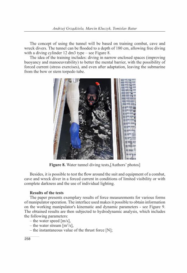
The concept of using the tunnel will be based on training combat, cave and wreck divers. The tunnel can be flooded to a depth of 180 cm, allowing free diving with a diving cylinder 12 dm3 type – see Figure 8.
The idea of the training includes: diving in narrow enclosed spaces (improving buoyancy and manoeuvrability) to better the mental barrier, with the possibility of forced current (stress exercises), and even after adaptation, leaving the submarine from the bow or stern torpedo tube.
Figure 8. Water tunnel diving tests,[Authors’ photos]
Besides, it is possible to test the flow around the suit and equipment of a combat, cave and wreck diver in a forced current in conditions of limited visibility or with complete darkness and the use of individual lighting.
Results of the testsThe paper presents exemplary results of force measurements for various forms
of manipulator operation. The interface used makes it possible to obtain information on the working manipulator's kinematic and dynamic parameters - see Figure 9. The obtained results are then subjected to hydrodynamic analysis, which includes the following parameters:
– the water speed [m/s],– the water stream [m3/s],– the instantaneous value of the thrust force [N];

259
The Stand for Fin Drives Energy Testing
– an average value of the thrust force [N],– an instantaneous value of the currents drawn by the motors no. 1 and 2 [mA],– an average value of the currents drawn by the motors no. 1 and 2 [mA],– the flipperfrequency [Hz],– the Strouhalnumer , where – water stream speed, – is a flipper
frequency, – is an amplitude of the fin trailing edge.
Figure 9. Performance of momentary thrust T produced by fin oscillating with water flow 0.26 m/s
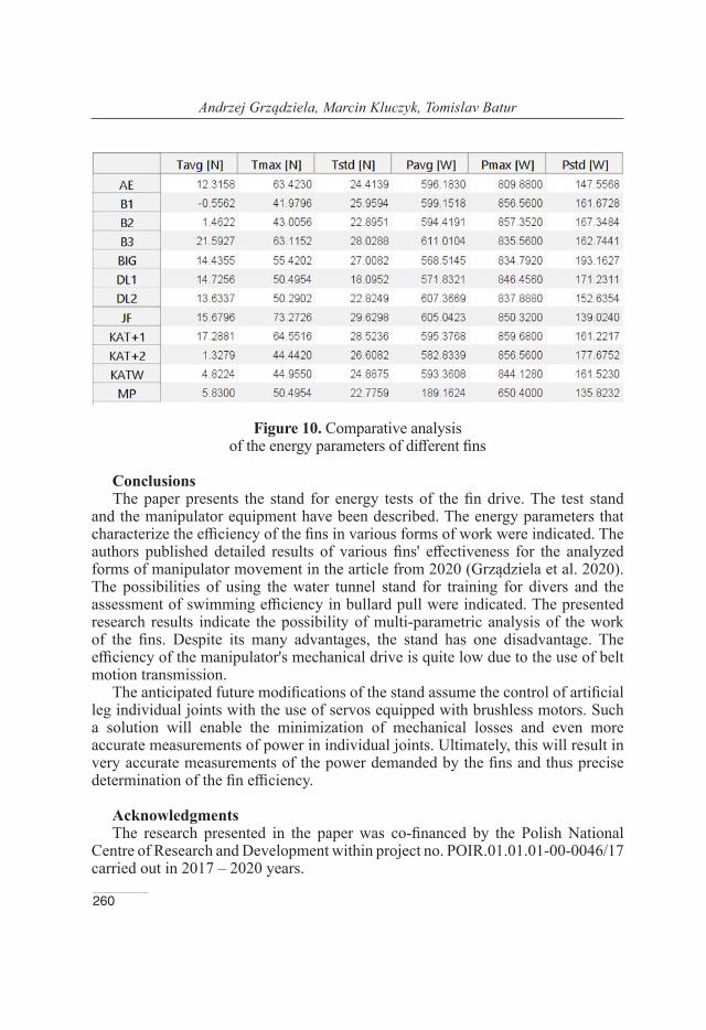
The implemented measurement system compares test results of different fins and other manipulator movement conditions (see Figure 10) (Praczyk et al. 2019). The analyzed parameters are mean values of thrust, mechanical efficiency, and kinematic and dynamic parameters peak values.
260
Andrzej Grządziela, Marcin Kluczyk, Tomislav Batur
Figure 10. Comparative analysis of the energy parameters of different fins
ConclusionsThe paper presents the stand for energy tests of the fin drive. The test stand
and the manipulator equipment have been described. The energy parameters that characterize the efficiency of the fins in various forms of work were indicated. The authors published detailed results of various fins' effectiveness for the analyzed forms of manipulator movement in the article from 2020 (Grządziela et al. 2020).The possibilities of using the water tunnel stand for training for divers and the assessment of swimming efficiency in bullard pull were indicated. The presented research results indicate the possibility of multi-parametric analysis of the work of the fins. Despite its many advantages, the stand has one disadvantage. The efficiency of the manipulator's mechanical drive is quite low due to the use of belt motion transmission.
The anticipated future modifications of the stand assume the control of artificial leg individual joints with the use of servos equipped with brushless motors. Such a solution will enable the minimization of mechanical losses and even more accurate measurements of power in individual joints. Ultimately, this will result in very accurate measurements of the power demanded by the fins and thus precise determination of the fin efficiency.
AcknowledgmentsThe research presented in the paper was co-financed by the Polish National
Centre of Research and Development within project no. POIR.01.01.01-00-0046/17 carried out in 2017 – 2020 years.

261
The Stand for Fin Drives Energy Testing
REFERENCESBideau, B., Colobert, B., Nicolas, G., Le Guerroué, G., Multon, F., &
Delamarche, P., 2003. Development of an active drag evaluation sys-tem (A.D.E.S.). Biomechanics and medicine in swimming 9, 51 – 56. France: Publications de l’Université de Saint Etienne.
Groth, B. H., Cibis, T., Schill R.O., Eskofier B.M., 2015. IMU-based Pose Determination of Scuba Divers’ Bodies and Shanks [June 2015]. Available from: doi: 0.1109/BSN.2015.7299376
Grządziela, A., Szymak, P., Piskur, P., 2020. Method for assessing the dynamics and efficiency of diving fins. Acta of Bioengineering and Biomechanics. 22(4), 139 – 150.
Minak, G., 2004. Evaluation of the performance of free-diving fins. Sports Eng. 7, 153–158. Available from: doi:10.1007/BF02844053
Nicolas G., Bideau B., Bideau N., Colobert B., LeGuerroue G., Dela-marche P., 2010. A new system for analyzing swim fin propulsion based on human kinematic data. Journal of Biomechanics 43, 1884 –1889.
Pendergast, D.R., Mollendorf, J., Logue, C., Samimy, S., 2003. Evaluation of fins used in underwater swimming. UHM 30(1), 55 – 71.
Praczyk T., Szymak P., Hożyń S., 2019. Applying Optical System to Model the Motion of Human Leg Moving in Water According to Swimming Style Crawl. Proceedings of 8th International Maritime Science Conference, 215 – 222 [Montenegro].
Wojtków M., Nikodem A. M., 2017. Biomechanics of diving: the influence of the swimming speed on the kinematics of lower limbs of professional divers. Acta of bioengineering and biomechanics. Available from: doi: 10.5277/ABB-00998-2017-01
Wylegala, J., Schafer-Owczarzak, F., Pendergast, D.R., 2007. Optimization of fin-swim training for SCUBA Divers. UHM 34(6), 431 – 437.
Zamparo, P., Pendergast, D. R., Termin, B., Minetti, A. E., 2002. How fins affect the economy and efficiency of human swimming. The Journal of Experimental Biology 205, 2665 – 2676.
Zamparo, P., 2008. Froude efficiency in human swimming. Comparative Biochemistry and Physiology Part A: Molecular & Integrative
262
Andrzej Grządziela, Marcin Kluczyk, Tomislav Batur
Physiology. 150(3S). ISSN 1095-6433. Available from: https://doi.org/10.1016/j.cbpa.2008.04.078
Andrzej GrządzielaORCID iD: 0000-0003-0284-7590
Polish Naval Academy, Gdynia, Poland
E-mail:[email protected]
Marcin KluczykORCID iD: 0000-0001-7357-6762
Polish Naval Academy, Gdynia, Poland
E-mail:[email protected]
Tomislav BaturFaculty of Maritime Science
University of SplitSplit, Croatia
E-mail: [email protected]