the special provisions for traffic signal … 3 - cpc16-0032... · (pn: cpc16-0032) 1. general...
TRANSCRIPT

THE SPECIAL PROVISIONS FOR
TRAFFIC SIGNAL INSTALLATION/ MODIFICATION
AT
East Commerce Way at Del Paso Road East Commerce Way at New Market Drive
City of Sacramento, California
January 2018
PREPARED FOR:
Schumacher Properties
PREPARED BY:

II
Electrical Specification Revisions
And
Electrical Special Provisions
Item Section – General, Line
Items, or Provisions
Revision Requested by
And Date
Recommended Revision
1 Include Revision Sheet
Eric Yap (1/10/2005)
Include Revision Sheet in the template.
2 City Furnished Equipment
Eric Yap (1/24/2005)
Change specification from Type 90 to Econolite controller.
3 PW to Transportation
Kaleb (2/2/2005)
Change Public Works to Transportation from Specifications.
4 Cost Breakdown John (3/3/05)
Minor change to title of section, included the word “electrical” on cost breakdown title.
5 Video Detection Eric Yap (3/30/05)
Add video detection to specification
6 Microwave Video Detection
John (6/21/05)
Add microwave video detection to specification
7 Irrigation Circuit Breaker
Kaleb (6/22/05)
Add irrigation circuit breaker to unmetered service pedestal.
8 Address and Name change
John (6/29/05)
Change address and locations.
9 Mastarm Luminaire
John (8/22/05)
Remove dimensions of mastarm luminaire.
10 Controller Wyscarver (8/22/05)
Add table for G3 and Opticom
11 CCTV Kaleb (10/28/05)
Add CCTV specifications
12 Video Detection Kaleb (11/11/05)
Modify language in video detection specification.
13 Cabinet and Visor Wyscarver (11/15/05)
Cabinet - US Traffic R38 & Displays - Tunnel Visors
14 Electrical Cost Breakdown
Staff (11/15/05)
Revision to Electrical cost Breakdown.
15 Order of Work Nicholas (2/8/06)
Revision to Order of Work – Section 1.31 Service pedestals shall be 1st order of work
16 Appeal Claims Hearing
Tim Mar (2/16/06)
Remove Item for Appeals Claim Hearing

III
17 Tree Pruning Staff Removal of tree pruning from specs 18 Claim Review
Section 1.48 Tim Mar (7/6/06)
Review by Claim Review committee and issuance of decision by department director
19 ADA Ped Pushbutton Height
Staff (9/1/06)
Change Pedestrian Pushbutton Height to CalTrans specifications.
20 EV John (11/8/06)
Change Modulated Light Signal Detection System and Optical Detector System TO Emergency Vehicle
Detector System 21 PG&E Contact John
(10/10/07) Added PG&E Contact name to section 1.21
22 Update to June 2007 Standards
John (2/20/08)
Update specs to reflect new 2007 Standard Specifications.
23 City furnished Equipment
John (12/1/10)
Updated City Furnished Equipment to Include Inspections.
24 City furnished equipment
Kaleb (4/21/11)
Ornamental Steetlight – Sealing of Streetlight Pole Foundation
25 Video Detection John (4/27/11)
Update Video Detection
26 Update Spec John (5/10/11)
Incorporate ITS specs into Generic Specs.
27 Update Signs on Mastarm Line Item
John (7/29/11)
Update Signs on Mastarm Line item.
28 Updated Spec to match Civil spec
John (7/29/11)
Updated Spec to Match Civil boilet plate spec
29 Updated CCTV John (3/2/12)
Updated Spec for latest CCTV camera, plus updated pull box item.
30 Updated Video Detection
John (3/2/12)
Updated Spec for Video Detection per TE
31 Updated Equipment to be
Supplied
John (3/28/12)
Updated Equipment to be Supplied.
32 Lockable Lid John (5/9/2012)
Pull Box Section updated with lockable lid.
33 Lighting Standard and Traffic Signal
John (5/17/2012)
Update spec: “Lighting Standards shall be in accordance with the latest California Department of Transportation
Standard Plans, unless otherwise specified in these Specifications or Plans.”
34 Cabinet TS2 Type 1
John (5/21/2012)
Inserted new city specification for cabinet, TS2 Type1
35 Countdown Ped Display
John (5/30/2012)
Update spec to reflect Traffic Engineering requirement.
36 Audible Pedestrian John (6/20/2012)
Removed Audible Pedestrian system. Older system.
37 Color of TS equipment
John (6/22/2012)
Paint color is black for TS displays, louvers, backplate, and pushbutton housing.

IV
38 Updated Ornamental SL
John (8/8/2012)
Incorporated Ornamental SL spec into document.
39 Updated various John (8/29/2012)
Updated pull box spec, to include concrete ring. Updated conduits to include duct seal. Updated line items to include removal USA marks and equipment marks.
40 Updated Transportation to
Public Works
John (10/5/2012)
Removed references to Transportation. Changed to Public Works
41 Updated Controller
John (10/5/2012)
Included ASC/3 TS2 Type 1, removed 2070N
42 LED Mastarm John (10/12/12)
Mastarm LED lamps included in specs.
43 Opticom John (10/22/12)
Updated model numbers for GPS opticom, per Vendor.
44 Ornamental and mastarm
John (11/1/12)
Updated specifications for Ornamental and Mastarm SL
45 APS John (11/20/12)
Accessible Pedestrian Signal inserted in specs.
46 Signs/Markings John (2/25/13)
Update line items for Signs and Markings.
47 Four Channel Rack Mount
Detector
John (4/3/13)
Update TS2/Type 1 cabinet to have a four channel rack mount loop detector.
48 Conductors Sompol (4/18/13)
Update to include printed and embossed labels for conductors.
49 Supplied Equipment
Kaleb (4/22/13)
Contractor orders equipment
50 Pull Box Kaleb (4/22/13)
Additional Mfgr added to list of acceptable pull boxes.
51 Bell Ends John (8/27/13)
Added to conduits
52 LED Approved List
John (8/27/13)
3 mfgr approved to list.
53 Approved Equal John (8/27/13)
Section updated: Equipment to be Supplied.
54 Water Quality John (8/27/13)
Section added: Water Quality Control
55 Cost Breakdown John (8/27/13)
Updated Electrical Cost Breakdown Language
56 Potholing and Changeable
Message Signs
John (8/29/2013)
Add Line Items for Potholing by Drilling and Changeable Message Signs
57 Striping Replaced after trenching
John (9/4/2013)
Conduit Installation – striping replaced after trenching.
58 Cabinet Layout John (5/20/2014)
Change shelf height of TS2 Type 1 Cabinet. 9 inch clearance.

V
59 Ornamental SL John (1/9/2015)
Ornamental Streetlight - Steel
60 PVC Glue Dave (1/12/2015)
PVC Cement – Blue Cement.
61 Network Switch John (3/25/2015)
New Network Switch Cisco IE 2000 (revised again on 4/16/2015)
62 Controller John (3/25/15)
McCain ATC eX
63 Remove and Salvage
John (7/1/15)
Remove and Salvage added to specifications
64 Traffic Signal Displays
John (11/20/2015)
Remove 8” displays from specifications.
65 Cat 6 Cable John (1/26/2017)
Add Belden Cat 6 Cable
66 Econolite Vision John (7/19/2017)
Added Econolite Vision to video detection equipment
67 Network Switch John (8/18/2017)
Changed switch from 8TC-L to 8TC-B, per TE directions.

I
TABLE OF CONTENTS
SPECIAL PROVISIONS FOR GENERIC STREET AND GENERIC STREET TRAFFIC SIGNAL PROJECT
(PN: CPC16-0032)
1. GENERAL REQUIREMENTS .................................................................................................1
1.1 SCOPE AND LOCATION OF WORK ...................................................................................................... 1
1.2 SPECIFICATIONS .................................................................................................................................... 1
1.3 ORDER OF WORK ................................................................................................................................... 2
1.4 COMPLETION TIME ................................................................................................................................ 2
1.5 PRE-BID INTERPRETATION OF CONTRACT DOCUMENTS ............................................................ 2
1.6 PROVIDING BONDS AND SURETY ...................................................................................................... 3
1.7 NO TRUCK HAUL ROUTE ON 28TH STREET SOUTH OF E STREET ............................................... 3
1.8 CERTIFICATE OF COMPLIANCE .......................................................................................................... 3
1.9 FINAL PAY QUANTITY .......................................................................................................................... 3
1.10 EQUIPMENT TO BE SUPPLIED ............................................................................................................. 3
1.11 HANDLING AND REMOVAL OF HAZARDOUS OR CONTAMINATED MATERIALS ................... 4
1.12 COORDINATION ..................................................................................................................................... 5
1.13 PROJECT SCHEDULING ......................................................................................................................... 6
1.14 PROTECTION OF EXISTING IMPROVEMENTS .................................................................................. 6
1.15 TRAFFIC HANDLING, PUBLIC SAFETY AND CONVENIENCE ....................................................... 7
1.16 USE OF SLIP-FORM MACHINES FOR CONCRETE CONSTRUCTION ............................................ 9
1.17 TRAFFIC CONTROL AND HANDLING FOR CONSTRUCTION STAKING ..................................... 9
1.18 PUBLIC NOTIFICATION ......................................................................................................................... 9
1.19 REMOVAL OF ON-STREET PARKING ............................................................................................... 10
1.20 EQUIPMENT LIST AND DRAWINGS SUBMITTALS ........................................................................ 11
1.21 PROOF OF COMPLIANCE WITH CONTRACT ................................................................................... 11
1.22 BACKFILLING OF VOIDS .................................................................................................................... 11
1.23 PAVEMENT CUTTING AND RESTORATION .................................................................................... 12
1.24 PROTECTION OF TREES ...................................................................................................................... 12
1.25 TREE TRIMMING .................................................................................................................................. 13
1.26 STOP WORK IF CULTURAL RESOURCES ARE DISCOVERED ...................................................... 15
1.27 HEALTH AND SAFETY......................................................................................................................... 15
1.28 PERMITS AND STAGING AREA .......................................................................................................... 16
1.29 TEMPORARY PAVEMENT MARKERS ............................................................................................... 16

II
1.30 EROSION AND SEDIMENT CONTROL .............................................................................................. 18
1.31 WATER QUALITY CONTROL ............................................................................................................. 18
1.32 ENCROACHMENT PERMIT ................................................................................................................. 21
2. ITEMS OF THE PROPOSAL (NOT APPLICABLE) ..........................................................22
3. ELECTRICAL PROVISIONS WHICH APPLY TO ALL ELECTRICAL ITEMS .........23
3.1 CITY EQUIPMENT TO BE REMOVED AND SALVAGED ............................................................................... 23
3.2 CITY FURNISHED EQUIPMENT .................................................................................................................. 23
3.3 CONDUIT MATERIAL ................................................................................................................................ 25
3.4 CONDUIT INSTALLATION .......................................................................................................................... 25
3.5 CONDUCTORS ........................................................................................................................................... 27
3.6 COMMUNICATION EQUIPMENT ................................................................................................................. 28
3.7 CCTV CAMERA SYSTEM .......................................................................................................................... 31
3.8 COUNT STATION SYSTEMS ....................................................................................................................... 33
3.9 DETECTOR CONDUCTOR LOOP ................................................................................................................. 36
3.10 DETECTOR HANDHOLES ........................................................................................................................... 38
3.11 DETECTOR LEAD-IN CABLE ..................................................................................................................... 39
3.12 EMERGENCY VEHICLE DETECTOR SYSTEM ............................................................................................. 40
3.13 EMERGENCY VEHICLE DETECTOR SYSTEM – GPS PRIORITY CONTROL SYSTEM ................................... 40
3.14 FIBER OPTIC ............................................................................................................................................. 41
3.15 FOUNDATIONS TO BE ABANDONED............................................................................................................ 43
3.16 INSPECTION............................................................................................................................................... 43
3.17 INTERCONNECT CABLE ............................................................................................................................. 43
3.18 MASTARM STREETLIGHT .......................................................................................................................... 45
3.19 METERED ELECTRICAL SERVICE .............................................................................................................. 46
3.20 MICROWAVE DETECTION SYSTEM DETAILS ............................................................................................ 48
3.21 ORNAMENTAL STREETLIGHT ................................................................................................................... 50
3.22 POST TOP LUMINAIRES ............................................................................................................................. 57
3.23 PULL BOXES ............................................................................................................................................. 58
3.24 TRAFFIC SIGNALS AND FITTINGS ............................................................................................................. 59
3.25 TRAFFIC SIGNAL CONTROLLER, ATC EX, NEMA TS2 TYPE 1 ............................................................... 64
3.26 TRAFFIC SIGNAL CONTROLLER, NEMA, ASC/3, TS2 TYPE 1 ................................................................. 65
3.27 TRAFFIC SIGNAL CONTROLLER 2070L ..................................................................................................... 66
3.28 TRAFFIC SIGNAL CABINET 332 ................................................................................................................. 75
3.29 TRAFFIC SIGNAL CABINET, TS2 TYPE 1, TYPE ‘R’ .................................................................................. 77

III
3.30 VIDEO DETECTION SYSTEM – ECONOLITE VISION ................................................................................... 91
3.31 MICROWAVE VEHICLE DETECTION ........................................................................................................... 99
3.32 WIRING ................................................................................................................................................... 100
4. SIGNING AND STRIPING ....................................................................................................101

1 revised 7/1/2015
SPECIAL PROVISIONS FOR
EAST COMMERCE WAY AT DEL PASO ROAD EAST COMMERCE WAY AT NEW MARKET DRIVE
(PN: CPC16-0032)
1. GENERAL REQUIREMENTS
Work under these Special Provisions includes general engineering contractor and electrical contractor tasks as defined by the California Business and Professional Code, the California Code of Regulations, and the California Contractors State License Board (CCSLB). The Contractor shall have a current and active Class A – General Engineering Contractor License issued by the CCSLB at the time of the bid submittal and throughout the construction period. The Contractor, and/or subcontractors performing electrical contractor tasks, shall also have a current and active Class C10 – Electrical Contractor License issued by the CCSLB at the time of the bid submittal and throughout the construction period. The Contractor shall include the license numbers, names of licensees, and any cited violations and violation investigations by the CCSLB within three years prior to the date of the bid submittal in the bid proposal. Failure to include this information will cause the bid to be deemed non-responsive.
1.1 SCOPE AND LOCATION OF WORK
Work to be performed under these Special Provisions includes furnishing and installing all necessary equipment and material to modify an existing traffic signal and install a new traffic signal as indicated on the Plan sheets and these Special Provisions at the following locations:
EAST COMMERCE WAY AT DEL PASO ROAD EAST COMMERCE WAY AT NEW MARKET DRIVE
INTERCONNECT ON EAST COMMERCE WAY BETWEEN DEL PASO ROAD
AND NEW MARKET DRIVE
1.2 SPECIFICATIONS
The work to be performed under this contract shall be in accordance with the Special Provisions contained herein. In these Special Provisions, reference is made to the City Standard Specifications of the City of Sacramento, adopted June 2007, referred to herein as "Standard Specifications". The contract shall be governed by Section 1 through 8 of the City Standard Specifications. The General Requirements of this contract shall be governed by these Special Provisions first, followed by Section 1 through Section 8 of the Standard Specifications. Other standards or specifications specified in these Special Provisions govern only the applicable technical specifications unless otherwise specified in these Special Provisions.
2 revised 7/1/2015
1.3 ORDER OF WORK
Order of work shall conform to the provisions in Section 5-1.05, “Order of Work,” of the State Standard Specifications and these special provisions. Contractor shall install the new service pedestal or modify the existing service pedestal as the first order of construction work. The Contractor shall notify the City Inspector upon completion of the service cabinet installation, so that the service cabinet is ready for SMUD power connection at the early stages of construction. Once SMUD powers the service cabinet, the main breaker shall be locked out to avoid any electrical hazard while terminating wires at the load side of the distribution breakers. The key should be kept with the City Inspector or a qualified electrician provided by the Contractor.
1.4 COMPLETION TIME
The time limit for the completion of all work is FORTY-FIVE (45) working days, commencing on the date set forth in the written Notice to Proceed issued by the City to the Contractor. The Contractor shall pay a sum in the amount of ONE THOUSAND AND FORTY DOLLARS ($1,040) as liquidated damages, and not as a penalty, for each calendar day delay after the expiration of working days. The Engineer will furnish the Contractor a weekly statement showing the number of working days charged to the contract for the preceding week and the number of working days charged to date. The Contractor will be allowed fifteen (15) calendar days in which to file a written protest setting forth in what respect the Contractor disagrees with the working day statement, otherwise the working day statement of the Engineer shall be deemed to have been accepted by the Contractor as correct.
1.5 PRE-BID INTERPRETATION OF CONTRACT DOCUMENTS
No oral representations or interpretation will be made to any bidder as to the meaning of the contract documents. Requests for interpretation shall be made in writing and delivered to the City at least seven (7) days before the time announced for opening the proposals. Interpretation, where necessary, will be made by the City in the form of an addendum to the contract documents and, when issued, will be sent as promptly as is practicable to all parties to whom the bid documents have been issued. All such addenda shall become part of the contract. Requests for information regarding this procedure or other similar information, shall be directed to the Engineer on the project. John Matoba, Department of Public Works, Engineering Services Division, 915 I Street, Room 2000, Sacramento, CA 95814, (916) 808-7891, or fax to (916) 808-7903 or email address: [email protected]. It shall also be the bidder's responsibility to call to the attention of the Engineer any missing pages or drawings in the contract documents including the addenda. These items shall be brought to the attention of the Engineer at least one (1) week prior to the bid opening date.

3 revised 7/1/2015
1.6 PROVIDING BONDS AND SURETY
The Contractor shall provide signed agreement and surety bonds within ten (10) calendar days after receipt of notice to award by the City and prior to award by the City Council. The Contractor shall be reimbursed for all surety bond costs should the City Council not award a contract.
1.7 NO TRUCK HAUL ROUTE ON 28TH STREET SOUTH OF E STREET
The Contractor and its subcontractors must not use 28th Street south of E Street as part of any haul route to and from the Bell Marine Co., Inc./ Harbor Sand and Gravel located at 200 28th Street. Acceptable routes to and from the facility are as follows: To enter facility:
North on 30th Street West on E Street North on 28th Street
To exit facility:
South on 28th Street East on C Street South on 29th Street
The Contractor shall be assessed an administrative penalty of $500 for each Contractor or subcontractor dump truck that uses 28th Street South of E Street to enter or exit the Bell Marine Co., Inc/Harbor Sand and Gravel.
1.8 CERTIFICATE OF COMPLIANCE
The Contractor shall provide the Engineer with a manufacturer's "Certificate of Compliance" at the Engineer's request within two weeks. The Certificate of Compliance shall clearly show that the material, equipment and/or work is in compliance with the tests and specifications set forth in these contract documents.
1.9 FINAL PAY QUANTITY
Final pay quantity is designated on the sealed bid proposal sheet with a “(F)”. Final pay quantity shall conform to Section 9-1.015 “Final Pay Items” of the State Standard Specifications, except that the final pay quantity designation shall be made on the bid proposal rather than the Plans.
1.10 EQUIPMENT TO BE SUPPLIED
All equipment, material and supplies called for in the Special Provisions shall be new and currently manufactured items, unless otherwise specified. All equipment shall be complete and in operation to the satisfaction of the Engineer at the time of acceptance of the work.

4 revised 7/1/2015
All incidental parts which are not shown on the Plans or specified herein and which are necessary to complete the project shall be furnished and installed as though such parts were shown on the Plans or specified herein. All equipment, materials, or supplies to be considered as an approved equal must be submitted to the City contact listed in Section 1.5, PREBID INTERPRETATION OF CONTRACT DOCUMENTS, for approval no less than ten (10) calendar days prior to the bid opening date. If the City finds said equipment, materials, or supplies to be acceptable, an addendum will be issued notifying all bidders by the close of business on Friday before the bid opening date. If there is no addendum accepting an approved equal, bidders shall submit bids based on the original specified equipment, materials, or supplies.
1.11 HANDLING AND REMOVAL OF HAZARDOUS OR CONTAMINATED MATERIALS
In the event hazardous or contaminated materials are encountered at the site for which separate handling or removal provisions have not been made in these Special Provisions, the Contractor shall stop work on that item, contact the Engineer and schedule his operations to work elsewhere on the site if possible. The City will be responsible for handling and removal of hazardous material or may request that the Contractor shall be available, through contract change order, to provide additional services as needed for the completion of the work. Additional services may consist of retaining a subcontractor who possesses a California license for hazardous substance removal and remedial actions. Hazardous or contaminated materials may only be removed and disposed of from the project site in accordance with the following provisions: 1. All work is to be completed in accordance with the following regulations and
requirements:
a. Chapter 6.5, Division 20, California Health and Safety Code.
b. California Administration Code, Title 22, relating to Handling, Storage, and Treatment of Hazardous Materials. 29 Code of Federal Regulation 1910.120 relating to Hazardous Waste Operation Safety Training.
c. City of Sacramento Building Code and the current edition of the Uniform
Building Code. 2. Coordination shall be made with the County of Sacramento Environmental
Management Department, Hazardous Materials Division, and the necessary applications shall be filed.

5 revised 7/1/2015
3. All hazardous materials shall be disposed of at an approved disposal site and shall only be hauled by a current California registered hazardous waste hauler using correct manifesting procedures and vehicles displaying a current Certificate of Compliance. The Contractor shall identify by name and address the site where toxic substances shall be disposed of. NO payment for removal and disposal services shall be made without a valid certificate from the approved disposal site that the material was delivered.
None of the aforementioned provisions shall be construed to relieve the Contractor from the Contractor's responsibility for the health and safety of all persons (including employees) and from the protection of property during the performance of the work. This requirement shall be applied continuously and not be limited to normal working hours.
1.12 COORDINATION
The Contractor shall coordinate his activities in a manner that will provide the least interference with the City's operations, other contractors and utility companies working in the area, and agencies exercising jurisdiction over the project area or portions thereof. 1. At a minimum the Contractor shall coordinate his operations with the following:
City Traffic Signal and Street Lighting Maintenance Shop Contractor shall notify Norm Colby, via the Resident Engineer, a minimum of five (5) working days before any electrical work begins at 808-6635.
City Fire Alarm
Contractor shall notify Doug Crawford, at 798-0673 or 277-6133, a minimum of five (5) working days prior to beginning work at each location.
Underground Service Alert
Contractor shall contact Underground Service Alert (USA) at 1-800-227-2600, a minimum of three (3) working days prior to any excavation.
Sacramento Municipal Utility District (SMUD) Contractor shall contact Michelle Zuniga, SMUD, at (916) 732-5726, at least 2 months before service hook-up is required, before service disconnect is required, before pole quadrants for risers need to be marked, before any poles need to be stood by SMUD, or before any overhead line heights need to be measured.
Pacific Bell Contractor shall contact Astrid Willard at (916) 453-6136 forty-eight hours (48) before service hook-up is required, before service disconnect is required, before pole quadrants for risers need to be marked, before any poles need to be stood by Pacific Bell, or before any overhead line heights need to be measured.
Pacific Gas and Electric (PG&E)

6 revised 7/1/2015
Contractor shall contact David Allen, Senior Field Engineer Technician for PG&E, at (916) 386-5277, and Larry Schlaht at (916) 386-5371at least 7 calendar days before start of construction.
2. A minimum of seven (7) calendar days prior to commencing work, the Contractor shall notify City Public Media and Communications Specialist, Linda Tucker (808-7523). The notice must answer the questions who, what, when, where and include the Project Manger’s name.
The Contractor shall be responsible for any garden refuse piles, which are inadvertently placed in the street between the time of City pickup and the Contractor's work. The cost for removing garden refuse piles shall be included in the unit prices bid for the various items of the proposal. The cost of coordination shall be included in the unit prices bid for the various items of the proposal and no additional compensation will be allowed therefor.
1.13 PROJECT SCHEDULING
The Contractor shall submit to the Engineer a practicable progress schedule and a schedule of values at the pre-construction meeting and within 5 days of the Engineer's written request at any other time. The Contractor shall furnish the schedules on a form of his choice. The progress schedule shall show the order in which the Contractor proposes to carry out the work, the dates on which he will start the features of the work and the contemplated dates for completion of the work. The schedule of values is submitted for use in determining progress payments. The progress schedules submitted shall be consistent in all respects with the time and order of work requirements of the contract. The Contractor shall submit, review and update a project schedule in accordance with Section 7-2 of the Standard Specifications. Subsequent to the time that submittal of a progress schedule and a schedule of values is required in accordance with these specifications, no progress payments will be made prior to the submittal of an acceptable project schedule.
1.14 PROTECTION OF EXISTING IMPROVEMENTS
The location, alignment, and depth of existing underground utilities as shown on the Plans are taken from public records and no responsibility is assumed for their accuracy. The Contractor's attention is directed to the provisions of Chapter 3.1 "PROTECTION OF PUBLIC UTILITIES IN PUBLIC CONTRACTS" of the California Government Code concerning protecting existing overhead and underground utilities. In particular, Section 4216 and Section 4217. Existing improvements, utilities and adjacent property shall be protected from damage resulting from the Contractor's operations. All trees, shrubbery, grass, fences, mail boxes, walls and other improvements including existing pavements, sidewalks, street

7 revised 7/1/2015
improvements, sprinkler systems and underground utilities and other improvements not to be removed under this contract shall be protected from damage by the Contractor throughout the construction period. All painted or other disfiguring markings on the pavement, sidewalk or gutters shall be removed by the Contractor before acceptance of the work. The Contractor will insure that utility services to customers in the project are maintained. The Contractor is responsible for the protection of and for damage to existing overhead and underground utility lines and services encountered during the course of construction. The Contractor shall notify the respective utility owner prior to any interruption of service. The Contractor is expected to "pothole" existing underground utilities a minimum of ten (10) working days in advance at any location where an existing utility may be in conflict with the proposed work. The cost of relocating existing overhead or underground utilities not specified on Plans to be relocated, but which the Contractor elects to relocate or cut and reconnect for his/her own convenience, shall be borne by the Contractor. No compensation will be paid to the Contractor for the maintenance and protection of existing utilities and facilities. The cost of such work shall be included in whatever bid item the Contractor deems appropriate.
1.15 TRAFFIC HANDLING, PUBLIC SAFETY AND CONVENIENCE
The contractor’s attention is directed to Sections 6 and 7 of the Standard Specifications. The contractor shall submit to the Engineer for review and approval a plan showing traffic control measures for vehicles, pedestrians and bicycles affected by the construction work. For emergency purposes, the responsible person in charge of the work must be reachable by phone 24 hours a day during the progress of the work. A 24-hour phone number shall be indicated on the permit application. The contractor shall adhere to guidelines as stated in Section 12.20.030 of Title 12 of the Sacramento City Code pertaining to Traffic Control Plan – Requirements, and shall conform to the current edition of the California MUTCD. Particular attention is directed to Chapter 6D – Pedestrian and Worker Safety and Chapter 6F – Temporary Traffic Control Zone Devices, Section 6F.68 – Detectable Edging for Pedestrians. Spillage resulting from hauling operations along or across any public traveled way shall be removed immediately by the Contractor at his expense. Construction operations shall be conducted in such a manner as to cause as little inconvenience as possible to abutting property owners.

8 revised 7/1/2015
Roadway excavation and the construction of embankments shall be conducted in such a manner as to provide a relatively smooth and even surface satisfactory for use by public traffic at all times. Skid resistance steel plates or other approved methods shall be used to cover all open excavations in the roadways and sidewalks at all times during construction. The plans shall be developed with the following requirements:
1. Working hours shall be between 8:30 AM and 4:00 PM Monday through Friday, unless otherwise approved by the Engineer.
2. All lanes of traffic, in each direction, must be open to traffic from 7:00 A.M. to
8:30 A.M. and from 4:00 P.M. to 6:00 P.M. and during periods when work is not in progress, unless otherwise specified by the Engineer.
3. A maximum of one (1) lane shall be closed to traffic in any direction when work is in progress. Flaggers shall be provided.
4. The Contractor shall submit a Traffic Control Plan to the Engineer in accordance with
Section 6 of the Standard Specifications. 5. All lanes shall be open during weekends, holidays, and when work is not in progress.
6. The Contractor shall furnish, install temporary stripes and maintain temporary
construction warning signs, lighting, flaggers, barricades, striping and other devices necessary to safeguard the general public and the work, and to provide for the safe and proper routing of all vehicular and of pedestrian traffic within and through the limits of the projects during the construction. The requirement shall apply continuously and shall not be limited to normal working hours.
7. The Contractor shall maintain existing electrical facilities and traffic and public
safety in accordance with Section 34 of the Standard Specifications and these Special Provisions.
8. Residential and Commercial driveways may only be closed after giving property
owners 72 hours of notice in advance of the closure. Driveways may only be closed during normal work periods and while the contractor is actively pursuing work which requires the driveway to be closed, except when forms are in place, or while concrete is being cured.
9. Commercial driveways shall remain open at all times, unless otherwise specified
by the City Inspector. The Contractor shall schedule the commercial driveways to be poured in two phases unless more than one driveway is available to the property. The Contractor shall coordinate the driveway closure with property owners’ 5 calendar days in advance.

9 revised 7/1/2015
10. All work within public streets and/or roadway right-of-way shall be done in an expeditious manner so as to cause as little inconvenience to the traveling public as possible. Skid-resistant steel plates or other approved methods shall be used to cover all open excavations in the roadway during non-working hours.
Full compensation for furnishing all labor, materials, tools, equipment and incidentals and for doing all work involved in public safety and convenience shall be considered as included in the prices paid for various contract items of work and no additional compensation will be allowed.
1.16 USE OF SLIP-FORM MACHINES FOR CONCRETE CONSTRUCTION
The Contractor may use concrete slip form machines to construct concrete curbs, gutters and sidewalks. The Contractor must maintain proposed lines and grades as shown on the plans. For curbs constructed on existing pavements, the contractor must construct the curb to eliminate any uneven lines and top of curb grade elevations. If in the sole discretion of the Engineer, these lines and grades are not maintained, the Contractor shall remove and replace the concrete at his/her costs.
1.17 TRAFFIC CONTROL AND HANDLING FOR CONSTRUCTION STAKING
The Contractor is responsible for providing traffic control (at the request of the City survey crew) to place the Contractor’s construction stakes within vehicle travel lanes of heavy volume streets and highways. Heavy volume streets are typically major and minor collectors and arterial streets; and are not alleys, local residential, local commercial, or local industrial streets. The cost to provide traffic control for construction staking in the vehicle travel lanes shall be included in the bid items the Contractor deems appropriate.
1.18 PUBLIC NOTIFICATION
The Contractor shall notify residents and businesses within the project limits in writing five (5) working days in advance of beginning work. The notice shall be approved by the Engineer and shall describe the work to be performed, the anticipated duration of construction and the name and telephone number of the Contractor's representative that can be reached 24 hours a day, 7 days a week. The Contractor shall be responsible for issuing a second notice to property owners five (5) working days in advance of commencing any work on private property. The Contractor shall include in the public notification flyers/postcards detailed procedures explaining precautions the homeowner can take to help prevent plugged utility service fixture problems. The Contractor shall submit to the Engineer for review and approval public notification flyers/postcards before they are issued to the public. Full compensation for this item shall be included in the prices paid for various contract items of work and no additional compensation will be allowed.

10 revised 7/1/2015
1.19 REMOVAL OF ON-STREET PARKING
In Metered Parking Areas: Seventy-two (72) hours prior to construction, the Contractor shall place signs adjacent to every third parking stall stating, "NO PARKING - (specific times and dates) - Tow Away" or "NO PARKING - (specific times and dates) - This Block". Contractor shall also contact the City Parking Division prior to placing barricades. Signs shall be placed before 1:00 PM on the day selected to allow sufficient time for City inspection. The Contractor shall request the City Parking Division to cover each parking meter, prior to construction, with a "NO PARKING" sign and the signs previously placed adjacent to every third stall shall be mounted on a barricade and moved into the parking stall at the Contractors expense. If the Contractor needs less than the entire block, every stall removed shall be barricaded in conjunction with the covering of parking meters. Where parking removal is necessary, at metered parking stalls, the Contractor shall coordinate with the City Parking Division three (3) days in advance and shall be responsible for the payment of parking removal fees (City Code Section 25.122-1). It is recommended that the Contractor consult with the City Parking Division (phone 916-808-5874) prior to submission of his bid to obtain an estimate of the fees for this project. Note: Typical fees are $29 to bag the first meter and $5 each additional meter. Daily meter fees are typically $2.25 each day Monday through Saturday. In Non-Metered Parking Areas: Seventy-two (72) hours prior to construction (except Monday work, barricades shall be placed on the prior Thursday), the Contractor shall place signed Type II barricades stating "NO PARKING - (specific times and dates) - Tow Away" or "NO PARKING - (specific times and dates) - This Block", at 50 to 60 foot intervals in the work area. The Contractor shall notify the City Parking Division (916-808-5874) prior to placing barricades. No fee is required in Non-metered zones. "NO PARKING" signs shall be approved by the Engineer prior to their use. "NO PARKING" signs and barricades shall be supplied by the Contractor. The Contractor shall notify the Engineer immediately after the "NO PARKING" signs are in place. Barricades shall be placed before 1:00 PM on the day selected to allow sufficient time for City inspection. Failure to comply with this section will prevent the City from towing vehicles parked within the proposed work area until the provisions of this section have been met and will

11 revised 7/1/2015
require rescheduling of planned work. Additionally, “NO PARKING” signs and barricades shall not be removed prior to removal/towing of vehicles in violation of posted “NO PARKING” signs. Payment shall include full compensation for furnishing all labor, materials, tools, equipment, incidentals and payment of all fees required to perform all work, as specified in these Special Provisions and as directed by the Engineer and shall be considered as included in the prices paid for the various contract items of work. No additional compensation will be allowed therefore.
1.20 EQUIPMENT LIST AND DRAWINGS SUBMITTALS
Equipment list and drawings shall be in accordance with Section 34-3 of the Standard Specifications and these Special Provisions. Unless otherwise permitted in writing by the Engineer, the Contractor shall, within twenty (20) days following notification of award of the contract submit to the Engineer for approval a listing of equipment and material which he/she proposes to furnish and install. The list shall be complete as to name of manufacturer, size and catalog number of unit, and shall be supplemented by other data, including detailed scale drawings and wiring drawings. A minimum of five (5) copies of the above data shall be submitted to the Engineer for review and approval. The Contractor shall submit to the Engineer a statement from each vendor supplying electrical equipment, including but not limited to, signal heads, standards, electroliers, luminaries, service pedestal and all other electrical equipment indicating that the orders for the materials required for this contract have been received and accepted by said vendor. The confirmed date of delivery to the contractor shall be indicated on the statement. All substitutions are subject to the approval of the Engineer.
1.21 PROOF OF COMPLIANCE WITH CONTRACT
In order that the Engineer may determine whether the Contractor has complied with the requirements of the contract documents not readily determinable through inspection and tests of plant, equipment, work, or materials, the Contractor shall at any time when requested, at the Contractor's expense, submit to the Engineer properly authenticated documents or other satisfactory proofs as to his compliance with such requirements.
1.22 BACKFILLING OF VOIDS
All voids resulting from the removal of trees, pipes, maintenance holes, ditch boxes, or other buried structures or objects shown on the Plans or called in these Special Provisions to be removed, shall be backfilled per the provisions of Section 26 (Trench Backfill) of the Standard Specifications. In the event job excavated native material is unsuitable for
12 revised 7/1/2015
backfill as determined by the Engineer, the Contractor shall furnish the required suitable backfill material. The cost to backfill voids as specified in the Special Provisions shall be included in the price bid for the respective items to remove trees, pipe, maintenance holes, ditch boxes, or other buried structures or objects, and no additional compensation shall be allowed.
1.23 PAVEMENT CUTTING AND RESTORATION
Pavement cutting and restoration shall conform to the provisions of Section 13-4 of the Standard Specifications and these Special Provisions. No pavement cutting shall precede pavement excavation by more than seven (7) calendar days unless approved by the Engineer. Prior to excavation in paved areas, pavement will be broken within the limits of expected excavation so as to prevent lifting of the pavement during excavation. Prior to restoration, the pavement shall be sawed or scored with an abrasive type pavement cutter (maximum blade width 1/4"). The proper tools and equipment shall be used so that the pavement will be cut to a neat and straight line six inches (6") beyond the limits of actual excavation. Where pavement cutting takes place more than five (5) calendar days before trench excavation, the Contractor shall fill the pavement cuts with asphaltic patching mix and maintain a smooth riding surface until trenching begins. Where the limits of excavation are located within twelve inches (12") of the edge of existing pavement or lip of the curb and/or gutter, the existing pavement within this twelve inches (12") shall also be removed. Full compensation for furnishing all labor, materials, tools, equipment and incidentals and for all work involved in this item shall be considered as included in the unit price bid for roadway excavation and removing and replacing asphaltic concrete pavement.
1.24 PROTECTION OF TREES
During construction the Contractor shall protect existing trees. All work near the trees shall be coordinated by the Contractor with the City Arborist, Duane Goosen, phone number 808-4996. The Contractor shall comply with direction as given by the City Arborist and the following City requirements regarding tree protection: No storage of materials or parking of vehicles may occur within the drip lines of the trees, except on paved streets. If, during construction, tree roots two inches (2") in diameter or greater are encountered, work shall stop immediately and the City Arborist shall be contacted for a root inspection, and roots shall not be cut without arborist approval. Roots approved by the arborist to be

13 revised 7/1/2015
pruned during the course of project construction shall be cleanly cut. If extensive root pruning is proposed an arborist inspection will determine if tree removal is necessary. If construction activities will affect any of the limbs of the trees, a certified arborist (certified by International Society of Arboriculture, Western Chapter) shall be consulted prior to the cutting or removal of any limb. Limbs approved by the arborist to be pruned during the course of project construction shall be cleanly cut. The Contractor shall be responsible for damages to trees. Trees damaged by the Contractor during construction activities shall be assessed by the City Arborist using the International Society of Arborists (ISA) appraisal guide or UFS standard diameter and area indexing. The Contractor's responsibility for damaged trees will be determined by the Arborist. Full compensation for furnishing all labor, materials, tools, equipment and incidentals and for doing all work involved in this section shall be considered as included in the prices paid for various contract items of work and no additional compensation will be allowed.
1.25 TREE TRIMMING
Trees identified by the Engineer to be trimmed shall be trimmed in accordance with the following specifications and as directed by the Engineer or project Arborist in conjunction with the City Arborist: General Conditions - This work is to be performed by a Tree Service Contractor, licensed and bonded to do business in the City of Sacramento. The work to be done will consist not only of this trimming and removal of branches and limbs but also disposal of material trimmed from these trees. Disposal of material will not be allowed at the City Dump. Contractor shall be aware of and shall comply with all ordinances governing and related to tree trimming work. Contractor shall furnish all labor, materials and equipment as required in performing the work described herein in strict accordance with these specifications and subject to the terms and conditions of this contract. Description of Work - The work shall be done primarily from truck mounted aerial platforms except where trees are inaccessible to trucks. All hand and power tools in the performance of this work shall be subject to inspection and approval of the Manager of the Urban Forest Services division or his designated representative who shall serve as the inspector for the City. In general, the standard tree trimming equipment shall be used and shall be maintained in a satisfactory condition at all times. All tools shall be clean, sharp, in proper working order and shall be checked for safety before each job. Inspection/Permit - The Contractor shall notify the Engineer prior to 8:00 a.m. on each day Contractor will be trimming trees.

14 revised 7/1/2015
The Contractor shall notify, 3 working days prior to tree trimming, the City Arborist, Duane Goosen, (916) 808-4996 and obtain, for this project, a permit for tree trimming within the City. Special Conditions - All licenses, insurance, etc., necessary to assume the legal responsibility for said work shall be acquired by the Contractor to cover the liabilities which might be caused by said work. All workmen shall comply with State Compensation Safety Rules and must wear safety equipment at all times while on the job. Adequate warning devices, barricades, guards, cones, etc., shall be placed and necessary precautions shall be taken by the Contractor to provide protection for the workers, pedestrians and vehicular traffic in the area. Work shall be scheduled and conducted in a cooperative manner in order to give the least possible interference with or annoyance to others. It shall be the responsibility of the Contractor to work out any cooperative work schedules as necessary. All tree work requiring climbing of trees shall be suspended during inclement weather. No trimmings or debris shall be left overnight on any of the work sites. Upon completion of a specific area, the site shall be left in a clean and orderly condition. It shall be the responsibility of the Contractor to repair any damages to adjacent property including shrubs, trees or other growth as well as structures along the route. To prevent the spread of Dutch elm disease, tree trimming tools shall be sprayed with Lysol before any tree trimming and after each tree has been trimmed. Personnel - All work shall be done by qualified and trained persons. They shall be familiar with tree climbing and trimming work in general and trained to work in trees of any size. A qualified foreman shall be provided to oversee and direct the work of each crew. Correct Cuts - All work shall be done in a professional and workmanlike manner. All cuts shall be made in accordance with the following sections in these Special Provisions, and as directed by the Engineer. Trees shall be trimmed at locations where there are tree conflicts and as directed by the Engineer or project Arborist in conjunction with the City Arborist. Tree trimming shall include the removal of any limbs or brush from limbs in order to achieve a clear space of at least six foot (6') radial distance from each luminaire. The results of the tree trimming shall produce an unobstructed cone of light that will illuminate a semicircle on the street at street level. The semicircle shall have a radius of forty feet (40') minimum on the street from the electrolier base. The unobstructed cone of light shall also illuminate an area at sidewalk level on the house side of the electrolier. This illuminated area shall extend fifteen feet (15') minimum from the base of the electrolier. Twigs, small limbs and sucker growth shall be removed with hand pruners, pole pruners or a fine toothed saw. All portions of a tree removed in the pruning operations, whether

15 revised 7/1/2015
small or large in diameter, shall be made just outside the branch bark ridge, parallel to and immediately adjacent to the tree limb from which the part is removed. Any dead wood and broken limbs encountered in the pruning operations shall be removed. Dead wood shall be defined as any portion of the tree having no living foliage, no live buds or no apparent life in the cambium layer. Final cuts on dead limbs shall not cut into the branch bark ridge or branch collar of the parent limb. Dead limbs larger than three-fourths of one inch (3/4") in diameter shall be removed by sawing. Broken limbs shall be removed except where branches have split and one portion of the branch can be saved by pruning to reduce lateral end weight. Shrubs shall be pruned as directed by the Engineer and shall conform to current ISA specifications. The cost of such work shall be included in whatever bid item the Contractor deems appropriate.
1.26 STOP WORK IF CULTURAL RESOURCES ARE DISCOVERED
If artifacts or stone, bone, or shell are uncovered during construction activities, the Contractor shall stop work within 100 feet of the find and notify the City, who will consult with a qualified archaeologist for an on-the-spot evaluation. Additional mitigation of the archaeological site will be the responsibility of the City. If bone is found and it appears to be human, the City will notify the Sacramento County coroner and the Native American Heritage Commission (916/322-7791).
1.27 HEALTH AND SAFETY
The Contractor is warned that existing sewers and appurtenances have been exposed to sewage and industrial wastes. These facilities shall therefore be considered contaminated with disease-causing organisms. Personnel in contact with contaminated facilities, debris, wastewater, or similar items shall be advised by the Contractor of the necessary precautions that must be taken to avoid becoming diseased. It is the Contractor’s responsibility to urge his personnel to observe a strict regime of proper hygienic precautions, including any inoculations recommended by the local public health officer. Because of the danger of solvents, gasoline, and other hazardous material in the existing sewers, these areas shall be considered hazardous to open flame, sparks, or unventilated occupancy. The Contractor shall be aware of these dangers and shall take the necessary measures to assure his personnel observe proper safety precautions when working in these areas. The Contractor shall not allow any wastewater to discharge from sewage collection systems onto adjacent lands of waters. In case of accidental discharge, the Contractor shall be responsible for containment, immediate cleanup and disposal at his own expense to the full satisfaction of the Engineer. Where containment is not possible, adequate disinfection

16 revised 7/1/2015
shall be provided by the Contractor at his expense as directed by the Engineer or agency with jurisdiction. If, in the opinion of the Engineer, the Contractor fails to adequately follow the above guidelines, he will make arrangements to have the work done by others, and have the cost charged to the Contractor.
1.28 PERMITS AND STAGING AREA
If the Contractor decides he/she needs additional working easement areas, work sites or material sites to facilitate his operation, it shall be his sole responsibility to locate, negotiate, obtain and pay for such additional working easements, work sites and material sites. The Contractor shall submit to the Engineer written authorization from the property owner of private property being used for the storage of equipment or materials. A copy of any written agreements entered into between the Contractor and the property owner concerning encroachment onto private property shall be provided to the Engineer prior to beginning any work on the property. All areas lying outside of the street right-of-way which are affected by the work shall be restored to the same, or better condition existing prior to the commencement of the work, to the satisfaction of the Engineer. The cost of necessary permits, all restoration, including but not limited to landscaping improvements, shall be included in the various items of work the Contractor deems appropriate, and no separate or additional compensation shall be made.
1.29 TEMPORARY PAVEMENT MARKERS
Temporary pavement markers shall be furnished and placed, maintained, and later removed as specified in these Special Provisions, and as directed by the Engineer. The following markers are approved for use on City of Sacramento street resurfacing projects:
Temporary Overlay marker (Types Y and W) manufactured by Davidson Plastics Company, 18726 East Valley Highway, Kent, Washington 98032, telephone (206) 251 8140.
Safe-Hit Temporary Pavement Marker, manufactured by Safe-Hit Corporation, 1930 West Winton Avenue, Building #11, Hayward, CA 95545, telephone (415) 783 6550.
Swareflex Pavement Marker (Models 3553, 3554, Cat Eyes Nos. 3002 and 3004), manufactured by Swareco and distributed by Servtech Plastics Inc., 1711 South California Street, Monrovia, CA 91016, telephone (818) 359 9248.

17 revised 7/1/2015
Stimsonite Construction Zone Marker (Model 66), manufactured by Amerace Corporation, Signal Products Division, 7542 North Natchez Avenue, Niles, IL 60648, telephone (312) 647 7717.
Flex-O-Lite Raised Construction Marker (RCM), manufactured by Flex-O-Lite, Lukens Company, P.O. Box 4366, St. Louis, MO 63123 0166, telephone (800) 325 9525.
3M Scotch-Lane A200 Pavement Marking System (reflective raised pavement marker on reflective traffic line tape), manufactured by 3M Company, Highway Safety Products, 1010 Hurley Way, Suite 300, Sacramento, CA 95825, telephone (916) 924 9605.
MV Plastics Chip Seal Marker (1280/1281 Series with Reflexite Polycarbonate, PC 1000, reflector unit), manufactured by MV Plastics, Inc., 533 W. Collines Avenue, Orange, CA 92667, telephone (714) 532-1522.
Temporary reflective raised pavement markers shall be placed in accordance with the manufacturer's instructions. Temporary reflective raised pavement markers shall be cemented to the surfacing with the adhesive recommended by the manufacturer, except epoxy adhesive shall not be used. At the direction of the Engineer, Temporary pavement striping may be required. After paving and or planning or grinding, temporary pavement markers shall be placed on all existing striped streets that are opened to public traffic prior to final striping in accordance with the striping diagrams. Temporary pavement markers that are damaged from any cause during the progress of the work shall be repaired or replaced by the Contractor at his expense. When no longer required for the work as determined by the Engineer, temporary pavement markers shall be removed in accordance with the provisions in Section 15-2, "Miscellaneous Highway Facilities," of the State Standard Specifications, except as otherwise provided herein. If the temporary pavement markers to be removed are on surfacing that is to be removed, the temporary pavement markers may be removed and disposed of in conjunction with the removal of the surfacing, providing such pavement markers do not interfere with the required traffic lane delineation, as determined by the Engineer. The 14-day waiting period for placing pavement markers on new asphalt concrete surfacing shall not apply to temporary pavement markers. Full compensation for furnishing, placing, maintaining, removing, and disposing of temporary pavement markers shall be considered as included in the prices paid for the various contract items and no additional compensation will be allowed therefore.

18 revised 7/1/2015
1.30 EROSION AND SEDIMENT CONTROL
See Section 1.31 Water Quality Control.
1.31 WATER QUALITY CONTROL
Erosion and Sediment Control shall be in accordance with Section 16 of the City Standard Specifications.
These requirements consist of regulations contained in the National Pollution Discharge Elimination System (NPDES) Storm Water General Permit issued to the City. The Contractor shall comply with the requirements and conditions of the General Permit during construction.
1. Dust Control
The Contractor shall comply with all City and County of Sacramento air pollution control rules, regulations, ordinances, and statutes which apply to any work performed pursuant to the contract, including any air pollution control rules, regulations, ordinances, and statutes, specified in the Government Code. The Contractor shall be responsible for the control of dust within the limits of the project at all times including weekends and holidays in addition to normal working days. The Contractor shall take whatever steps are necessary or required by the Engineer to eliminate the nuisance of blowing dust without causing sediment, debris or litter to enter the City storm drain system.
2. Erosion, Sediment, and Pollution Control
The Contractor shall be responsible for controlling erosion and sedimentation within the limits of the project at all times during the course of construction including evenings, weekends and holidays in addition to normal working days. The Contractor shall prevent sediment and construction debris from entering the City storm drain system.
The Contractor shall provide the following erosion, sediment, and pollution control Best Management Practices (BMPs) when and where applicable (also see attached details):
a. Filter Bags in and Gravel bags around any storm drain inlets, which receive runoff from the limits of the construction zone, including storage and staging areas. Alternative storm drain inlet protection BMPs can be used with approval of the Engineer.
b. Covering of material piles and/or gravel berms (or approved equal) around material piles as required to prevent migration of material to gutters or storm drains.
c. Gutter flowlines are to be kept unimpeded and free of soil, debris and construction materials at all times.
d. Stabilized construction entrance at any soil to concrete/asphalt interface used by Contractor vehicles and equipment.

19 revised 7/1/2015
e. Silt fences, fiber rolls or approved equal at any soil to concrete/asphalt interface at which soil may be washed onto the concrete/asphalt.
f. Wash water, slurry and sediment from concrete or asphalt sawcutting operations shall not be allowed to enter the City storm drain system, but instead must be collected and disposed of, by the Contractor, in some manner approved by the Engineer.
The Contractor is required to implement, at a minimum, the following housekeeping practices: site cleanup, solid waste management, material storage and delivery area, concrete waste management, and spill prevention and control.
3. Site Cleanup
The Contractor shall keep the project site clean and free of dust, mud, and debris resulting from the Contractor's operations. Daily clean up throughout the project shall be required as the Contractor progresses with the work. Extra precautions and cleanup efforts shall be made prior to weekends and holidays.
Daily or as needed, all paved areas within the limits of the project shall be cleaned and free of sediments, asphalt, concrete and any other construction debris. The Contractor will not be allowed to clean sediment and debris from the street by using water to wash down streets. The streets will be allowed to be washed only after the streets have been thoroughly swept and/or vacuumed and inlet protection has been placed at all storm drain inlets to catch any remaining sediments from the streets.
Spillage of earth, gravel, concrete, asphalt, or other materials resulting from hauling operations along or across any public traveled way shall be removed immediately by the Contractor at his expense. If site is not kept sufficiently clean the City will take measures to clean it and back charge the Contractor.
Throughout the duration of the project the Contractor will be required to inspect and maintain, in effective condition, all erosion, sediment, and pollution control BMPs before and after each storm event and as needed. The contractor shall immediately correct or replace any ineffective BMPs.
The Contractor shall prepare and submit an erosion, sediment and pollution control plan (ESC Plan) to the Engineer for review. The submittal shall include a description of all erosion, sediment and pollution control BMPs proposed to be used to prevent sediment and other sources of pollution from entering the City storm drain system as well as a site plan showing their placement. The ESC Plan shall be submitted a minimum of 48 hours prior to start of the work. The Contractor will not be allowed to begin work until an accepted ESC Plan is on file with the Engineer. The erosion, sediment and pollution control plan shall be updated as necessary and re-submitted to the Engineer.

20 revised 7/1/2015
4. Enforcement
Per City Code Sections 15.88, 13.16 and 1.28, the Contractor shall be subject to Notices of Violation (NOVs) resulting in possible Stop Work Orders and Administrative Penalties of up to $4,999 per day for non-compliance of this section of the Special Provisions.
Per the State’s Porter Cologne Water Quality Act, the Contractor shall also be subject to inspection by Staff from the Central Valley Regional Water Quality Control Board who have the
authority to issue Notices of Violation (NOVs) and Penalties of up to $10,000 per day for non-compliance. The Contractor shall be liable for any fines issued to the project by the State or Federal Government for NPDES non-compliance due to Contractor negligence.
The City reserves the right to take corrective action and withhold the City’s costs for corrective action from progress payments or final payment in accordance with Section 7, Retention of Sums Charged against the Contractor, of the Agreement.
Any fines, including third-party claims, levied against the Agency as a result of Contractor’s non-compliance are the Contractor’s sole responsibility and will be withheld from progress payments or final payment in accordance with Section 7, Retention of Sums Charged against the Contractor, of the Agreement.
No compensation will be paid to the Contractor for water quality control. The cost of such work shall be included in whatever bid item the Contractor deems appropriate.
5. Housekeeping Practices
The Contractor shall implement housekeeping practices during the construction of this project. The Contractor is required to implement, at a minimum, the following housekeeping practices: solid waste management, material storage and delivery area, concrete waste management, and spill prevention and control.
Solid Waste Management: Contractor shall maintain a clean construction site. Contractor shall provide designated areas for waste collection. The waste collection areas shall be leak-proof containers with lids or covers. Site trash shall be collected daily and placed in the disposal containers. The Contractor shall make arrangements for regular waste collection. The Contractor shall also regularly inspect the waste disposal areas to determine if potential pollutant discharges exist.
Material Storage and Delivery Area: Contractor shall provide one central material storage and delivery area (MSDA) for the duration of the project. This area shall be fenced or otherwise protected such that runoff will not be allowed to leave the MSDA site. The Contractor shall regularly inspect the MSDA site to ensure that any hazardous or non-hazardous materials have not spilled.
Concrete Waste Management: The Contractor shall arrange for concrete wastes to be disposed of off-site or in one designated area. Concrete wastes, including left-over concrete and material from washing out the concrete truck, shall not be disposed to the

21 revised 7/1/2015
storm drain system via curb and gutter. If a designated area is provided, the site shall be bermed to allow the concrete to dry. The dried concrete waste shall be removed and disposed of properly by the Contractor at his expense.
Spill Prevention and Control: The Contractor shall be responsible for instructing employees and sub-contractors about preventing spills of hazardous materials and controlling spills if they occur. Proper spill control and cleanup materials shall be kept on site near the storage area and updated as materials change on site. More information about control measures and housekeeping practices can be obtained by referring to the City of Sacramento's Administrative and Technical Procedures Manual for Grading, Erosion and Sediment Control available at 1395 35th Avenue, Sacramento, CA 95822.
1.32 ENCROACHMENT PERMIT
The City is in the process of acquiring a Caltrans Encroachment Permit. Prior to start of work within the State of California’s right-of-way or work affecting the State of California facilities, the Contractor will be required to obtain an Encroachment Permit at the following State of California Transportation office: CALTRANS, DISTRICT 03 PERMIT ENGINEER 703 “B” Street P.O. Box 911
Marysville, CA 95901 (530) 741-5374
The Contractor shall pay the applicable fees due at the time of application. A copy of the City’s Encroachment Permit is available upon request. Full compensation for conforming to the requirements in this permit, including the cost of the permit, shall be considered as included in the contract prices paid for the various item or work and no additional compensation will be allowed therefore.

22 revised 7/1/2015
2. ITEMS OF THE PROPOSAL (NOT APPLICABLE)

23 revised 7/1/2015
ELECTRICAL PROVISIONS WHICH APPLY TO ALL ELECTRICAL ITEMS
ITEMS
3.1 City Equipment to be Removed and Salvaged
All City of Sacramento equipment to be salvaged shall be returned to the City of Sacramento Corporation Yard. The City has two corporation yards: Corporate Center South, 5730 24th Street, Building 11, Sacramento, California and the Corporate Center North, 918 Del Paso Road, Sacramento, California. Contractor is responsible to provide machinery and manpower to unload and load all salvaged equipment. Loading, unloading, pick-up, and delivery of these items will be considered included in the price bid for various items and no additional compensation will be allowed therefor. The Contractor shall schedule the delivery of salvaged equipment with the City Inspector. Equipment drop-off shall be done in the presence of the City Inspector or his designated representative. The Contractor shall be responsible for all damages that occur in connection with the care and protection of all City salvaged equipment.
3.2 City Furnished Equipment
The Contractor shall pick-up all City furnished equipment at the City Corporation Yard. The City has two corporation yards: Corporate Center South, 5730 24th Street, Building 11, Sacramento, California and the Corporate Center North, 918 Del Paso Road, Sacramento, California, and deliver these items to the job site. Contractor is responsible to provide machinery and manpower to unload and load all city furnished equipment. Loading, unloading, pick-up, and delivery of these items will be considered included in the price bid for various items and no additional compensation will be allowed therefor. The Contractor shall schedule the equipment pick-up with the City Inspector. Equipment pick-up shall be done in the presence of the City Inspector or his designated representative. The Contractor shall be responsible for all damages that occur in connection with the care and protection of all materials and equipment until the completion and final acceptance of the work by the City. The Contractor’s responsibility for City supplied equipment shall be in accordance with Section 6-1.02, “State-Furnished Materials,” of the State Standard Specifications. Traffic Signal Controller and Cabinet - The City of Sacramento shall provide one (1) Type “R” cabinet and one (1) Econolite controller as indicated on the Plans. The City will provide one set of anchor bolts with the City supplied equipment. The Contractor shall provide and construct the foundation for the Type R cabinet in accordance with the State Standard Plans, these Special Provisions, the Plans and as designated by the Engineer. The Contractor shall install all City furnished equipment on the foundations and make all wire connections as directed by the Engineer. City forces will program all

24 revised 7/1/2015
controllers, conflict monitors, and detector sensor units. The Contractor shall notify the Traffic Signal Maintenance Shop, (916) 433-6314, ten (10) working days prior to the date of installation of the controller cabinet. Traffic Signal Standards - The City of Sacramento shall provide the traffic signal standards as specified in the Plan sheets. The City will provide one set of anchor bolts with the City supplied equipment. The Contractor shall provide and construct the foundations for the traffic signal standards in accordance with the State Standard Plans, these Special Provisions, the Plans and as designated by the Engineer. The Contractor shall install all City furnished equipment on the foundations and make all wire connections as directed by the Engineer. City forces will program all controllers, conflict monitors, and detector sensor units. The Contractor shall notify the Traffic Signal Maintenance Shop, (916) 433-6314, ten (10) working days prior to the date of installation of the traffic signal standards. Ornamental Streetlight - The City of Sacramento shall supply all ornamental streetlight standards, luminaires, and lamps as indicated on the Plans for this project. In addition, the City will provide one set of anchor bolts for each streetlight standard and luminaire to be installed. The Contractor shall construct the foundations for the street lighting standards as indicated on the Plans and as designated by the Engineer. The Contractor shall install the ornamental street lighting standards on the foundations and make all wire connections as directed by the Engineer. Video Detection Camera/System - The City of Sacramento shall provide Video Detection Camera/System with coax cable and power cable as indicated on the Plans. The Contractor shall install all City furnished equipment and make all wire connections as directed by the Engineer. Contractor shall configure and program both the video detection camera/system and traffic signal controller to detect vehicles for a fully functional traffic signal system. The Contractor shall notify the Traffic Signal Maintenance Shop, (916) 433-6314, ten (10) working days prior to the date of installation of equipment. The quantity of equipment are shown on the plan sheets. For the video detection camera/system, the contractor shall contact Econolite Control Products Inc, Barry Rodinsky, District Manager, (510) 562-3215. West Gate Business Center, 1399 Davis Street Suite 305, San Leandro, CA 94577 All costs shall be incorporated into the lump sum bid price. Microwave Video Detection System - The City of Sacramento shall provide Microwave Video Detection System as indicated on the Plans. The Contractor shall install all City furnished equipment and make all wire connections as directed by the Engineer. Contractor shall configure and program both the video detection camera/system and traffic signal controller to detect vehicles for a fully functional traffic signal system. The Contractor shall notify the Traffic Signal Maintenance Shop, (916) 433-6314, ten (10) working days prior to the date of installation of equipment. . The quantity of equipment are shown on the plan sheets.

25 revised 7/1/2015
3.3 Conduit Material
Conduit to be installed underground shall be Schedule 40 polyvinyl chloride (PVC) or Schedule 40 polyethylene conduit as described herein unless otherwise indicated or specified. PVC conduit shall comply with the specifications in Section 34-10 of the City Standard Specifications. High-density polyethylene conduit shall comply with the following specifications: Conduit shall be fabricated from polyethylene shall be in conformance with applicable ASTM and NEMA standards and Article 347 of the National Electrical Code. Non-black polyethylene conduit shall contain not less than 2500 parts per million (ppm) of a hindered amain ultraviolet light stabilizer. Ultraviolet stabilization additive for black polyethylene conduit shall consist of a carbon black loading of 2.5% 0.5% by weight. Conduit shall be manufactured from high-density polyethylene resin designated as Type III, Category 5, Class C, Grade P34 material in accordance with ASTM D1248. Duct seal shall be installed on all conduits. All new conduits starting/terminating in pull boxes shall have End Bells.
3.4 Conduit Installation
Conduit installation shall be in accordance with Section 34-9, 34-10 of the Standard Specifications and as modified by these Special Provisions. “Jet-rodding” is not permitted. Conduits terminating in pull boxes, standards, pedestals and cabinets shall rise vertically and shall not slope in any direction. Conduits terminating in standards, pedestals, and cabinets shall terminate one and one-half inches (1½") above finished grade. Conduits shown on the Plans to be adjacent and parallel to each other shall be installed in the same trench or drill hole unless otherwise specified or directed by the Engineer. Under the sidewalk, conduit shall be laid to a depth of not less than eighteen inches (18”) below the sidewalk grade. Conduits shall be installed by trenching or directional drilling method. All applicable requirements in these Special Provisions to locate, and to protect existing utilities, utility laterals, obstructions, and other facilities in the area shall be conformed to and no additional compensation will be allowed therefor. Contractor is responsible for any damage and the repair of any existing facilities damaged by his/her trenching or drilling operations. Contractor is responsible for any potholing necessary and cost for potholing shall also be included in price paid for applicable items of work and no additional compensation will be allowed therefor. All trenching or drilling work shall be contained within the City right-of-way. If utilities or other obstacles are encountered at the specified conduit depth, any additional drilling required to avoid the obstacle shall be made at the Contractor’s expense and no additional compensation will be allowed therefor. Location
26 revised 7/1/2015
of trenching and drill holes shall take into consideration minimal impact to the street pavement while still meeting the requirements of these Special Provisions. Contractor shall replace roadway striping and markings with same material if damaged by directional drilling, bore pits, potholes, or trenching. Replacement striping and markings shall be thermoplastic or paint, per the City of Sacramento Standards. Contractor shall use the following PVC pipe cement to join conduits and fittings: Premier Cement PVC All Temperature One Step Blue or Christy’s Red Hot Blue Glue for Schedule 80 thru 4” diameter. A. Trenching Method Installation of conduit by trenching shall be in conformance with the Plans and these Special Provisions. See plan sheets for trench details. Trenches shall be backfilled or covered at the end of each work day. All conduit installed by trenching shall be anchored every 15 feet to the bottom of the trench, with an approved method, so as to prevent the conduit from floating when the concrete is backfilled into the trench.
1. Trenches in reconstructed roadways shall be backfilled with slurry portland
cement per cubic yard and fine type aggregate as defined in the Standard Specifications Section 10-5. A red oxide in the amount of 5 lbs. per cubic yard shall be mixed uniformly throughout the slurry cement. See plan sheets for amount of sack slurry and depth of conduit(s).
2. Trenches in existing roadways shall use the “T-Trench” method. The
portion over the trench shall be paved with asphalt concrete, Type A with ¾” aggregate (coarse); except on residential streets where the base course shall be Type A, ¾” aggregate (coarse) and surface coarse shall be Type B, ½” aggregate, (medium), per Section 22 of the City Standard Specifications, unless otherwise directed by the Engineer. See plan sheets for width and thickness of asphalt concrete over trench. Trenches shall be backfilled with slurry portland cement per cubic yard and fine type aggregate as defined in the Standard Specifications Section 10-5. A red oxide in the amount of 5 lbs. per cubic yard shall be mixed uniformly throughout the slurry cement. See plan sheets for amount of sack slurry.
B. Directional Drilling Method Installation of conduit by directional drilling shall be in conformance with the Plans and these Special Provisions. Conduits shall be installed such that the top of the conduit(s) are not less than eighteen inches (18”) below the finished grade in sidewalk areas and not less than thirty inches (30”) in all other areas except as otherwise specified or directed by the Engineer.

27 revised 7/1/2015
Prior to the start of directional drilling, the Contractor shall submit a plan which identifies location and size of proposed drill holes, describes process for identifying/locating existing utility services and other underground utilities or obstructions, identifies a proposed “drilling corridor” to avoid conflicts with existing utilities, services and other facilities. This plan shall be submitted to the Engineer a minimum of ten (10) working days prior to the start of work. The Contractor will not be allowed to directional drill until an approved plan is on file with the Engineer Directional drilling shall be performed by the technique of creating and directing a bore hole along a predetermined path to a specified targeted location where indicated on the plans to install conduits. The technique shall involve the use of mechanical and hydraulic equipment to change the boring course and shall use instrumentation to monitor the location and orientation of the boring head assembly along the predetermined course. Drilling shall be accomplished with fluid-assisted mechanical cutting. Unless otherwise approved, boring fluids shall be a mixture of bentonite and water or polymers and additives. Bentonite sealants and water will be used to lubricate the drilling head. It is mandatory that minimum pressures and flow rates be used during drilling operations so as not to fracture the subgrade material around and/or above the bore. Uncontrolled jetting (where the primary purpose is to use fluid force to erode soil for creation of the final bore hold diameter) is prohibited. The drilling system shall utilize small-diameter fluid jets to fracture, and mechanical cutters to cut and excavate the soil as the head advances forward. All drilling shall be located a minimum of three feet (3’) from the center of all existing maintenance holes. Drilling that run parallel to any sanitary sewer or storm drainage lines shall maintain a minimum clearance of three feet (3’) measured from the centerline of the sewer or drainage line to the adjacent side of the drill hole. Drilling that crosses any sewer or drainage line shall cross at 90 degrees to the line or at a minimum of 45 degrees if a 90 degree crossing is not possible.
3.5 Conductors
Conductors shall be in accordance with Section 34-12 of the Standard Specifications, except for the following: 1. If the existing ground wire (green 1#10 THW) is used as a pullwire, a new ground
wire shall be pulled with the new conductors or cables, unless otherwise specified. 2. Unless otherwise noted, insulation Types THHN and THWN are not approved for
installation. 3. The electrolier leads from base to lamp socket shall be No. 12 THW solid wire
with 45 mils insulation suitable for 600-volt service for historic decorative, post top and mast arm electroliers.

28 revised 7/1/2015
4. All conductors of AWG #10 or larger shall be identified by printed and embossed labels. #1, #6, #8, #10 conductors shall be printed and embossed. a) Both printed and embossed labels shall clearly identify the UL listing, insulation
type, voltage rating, AWG number, and the City of Sacramento. b) The printed label and the embossed label shall be placed at approximately 90
degrees separation around the center of the conductors. c) Labels shall appear every one foot interval. Embossed labels shall be between
0.002” to 0.003” in depth and shall not damage the conductors. Label heights shall be no less than 3/32” for AWG #8 or larger, and shall be no less than 2/32” for AWG #10.
3.6 Communication Equipment
The following communication equipment shall be provided, installed and configured per the Plans and Special Provisions. A. Network Switch with Power Supply Network Switch shall be manufactured by Cisco, Model IE-2000-8TC-B or approved equal. The network switch shall have the following:
Power Supply shall be Cisco, PWR-IE50W-AC-IEC. Cisco 100Base – X small Form Factor Pluggable Module - Two (2) GLC-FE-
100LX-RGD – Cisco device hot-swappable I/O device that plugs into Fast Ethernet ports, dual-rate Fast/Gigabit Ethernet ports, or Gigabit Ethernet ports of Cisco Switch linking the port with the fiber cabling network.
Network Switch shall meet the following requirements:
Industrial grade DIN rail mountable Ethernet connectivity Operate under 14 degrees Fahrenheit to 140 degrees Fahrenheit, and under
vibration and shock Eight (8) 10/100 Base-T Ethernet ports (Small Form0Factor Pluggable (SFP)
downlinks) Two (2) gigabit combo ports: SFP Swappable SD flash card and mini-USB connector LAN lite Software 5-year warranty
For Type R cabinet, network switch shall be mounted on a DIN rail attached to aluminum stock for support. The DIN rail and aluminum stock shall be mounted to the cabinet channel rails.

29 revised 7/1/2015
The Contractor is responsible for making all connections per manufacturer recommendations. Power Supply for Network Switch shall meet the following requirements:
Compatible with Cisco IE 2000 Series industrial grade switch DIN rail mountable Input: 100-120 VAC or 200-240 VAC, manually selected AC, 50-60 Hz Operate under 14 degrees Fahrenheit to 140 degrees Fahrenheit, and under
vibration and shock 5-year warranty
Power Supply for Network Switch shall be installed in cabinet. For Type R cabinet, power supply for network switch shall be mounted on a DIN rail attached to aluminum stock for support. The DIN rail and aluminum stock shall be mounted to the cabinet channel rails. The Contractor is responsible for making all connections and shall be made per manufacturer’s recommendations to insure that the switch is powered. See Plans for further details. B. Surge Suppressor Power Strip Surge Suppressors shall meet the following requirements:
120 VAC 60 Hz All metal housing Isolated filter banks 2350 joule/97,000 amps rating 6 outlets 6 foot cord
Surge Suppressors shall be manufactured by Tripp-Lite Power Protection, Model ISOBAR6ULTRA or approved equal. Surge Suppressors are to be installed in Type R and Type 332 cabinets at locations where a network fiber or DSL switch are being installed as noted on the Plans. For Type R cabinet, the Surge Suppressor shall be mounted to the cabinet channel rail, and must be wired to the load side of the 15-amp main breaker in the cabinet. For the Type 332 cabinet, the Surge Suppressor shall be mounted on 2” aluminum stock on the back side of the cabinet near the top using the existing 19” rack. The Surge Suppressor must be plugged into the equipment receptacle on the back of the power assembly of the 332 cabinet. See Plans for further details. C. Termination Block Termination block shall meet the following requirements:

30 revised 7/1/2015
EIA/TIA-568 Category 5e Terminates 22 - 26 AWG solid insulated cable Terminates 18 - 19 AWG solid stripped cable 25 pair capacity Fanning strips for horizontal cable management Made of high impact flame retardant thermoplastic Snap on cover
Termination block shall be manufactured by Siemon, Model S66M1-25 or approved equal. The Contractor shall install and terminate signal interconnect and DSL equipment using specified terminal block at all locations where signal interconnect is terminated to DSL communication equipment. Connection to the terminal block shall be made per manufacturer’s recommendation. Bridging clips shall be provided as required to connect interconnect and DSL equipment. Terminal block shall be installed to traffic signal cabinet channel rail using aluminum stock. D. DSL Network Switch (Copper Infrastructure) DSL Network Switch shall meet the following requirements:
Deliver a high speed Ethernet link over copper and fiber infrastructure Speeds up to 100 Mbps of symmetrical Ethernet traffic Capable of bonding copper pairs into two directions 8 copper high speed pairs. Compatible of bonding 8 high speed links into 2
Ethernet channels. G.SHDSL Drop and repeat Ethernet traffic Minimum of 4 – 10/100M copper Ethernet ports. 1-100 Base FX optical SFP port. Environmentally hardened casing Manufacturer approved power supply Capable of Layer 2 network management
Equipment shall be manufactured by Actelis, Model ML688 or approved equal. DSL high speed copper links shall be terminated to interconnect cable per manufacturer’s recommendations. The Contractor is responsible for providing a continuous link between intersections. The DSL Network Switch shall be placed on the top shelf inside the traffic signal controller cabinet. The Contactor shall work with the manufacturer’s representative and City staff to configure DSL Network Switch to provide the highest speed link possible. Copper pair signal quality results from the DSL Network Switch

31 revised 7/1/2015
shall be provided to the City. The Network IP address will be provided to the Contractor by the City. Functional Test The DSL Network Switch shall be programmed to provide a high speed link over the traffic signal interconnect. The DSL shall be configured to obtain a link speed as specified above; deviation from the specification shall be approved by the Engineer. The network shall transmit IP video at 80% of the approved link speed. Data and video latency shall be minimized. E. DSL Switch (SFP Module) DSL Network Switch SFP module shall meet the following requirements:
Provide 125 Mbps data rate Transmit and receive over single mode fiber using 1310 nm wavelength Transmission distance of 15km Dual LC connector
Equipment shall be manufactured by Actelis, Model 506R00032 or approved equal.
3.7 CCTV Camera System
A. General The CCTV Camera shall be AXIS Q6115-E PTZ Dome Network Camera or pre-approved equal. System shall include PoE mid-span power injector, mounting brackets and cat 6 cabling. The CCTV system for traffic monitoring shall connect to the city network through the Ethernet switch in the traffic signal cabinet. All cabling between the camera and the traffic signal cabinet shall be Category 6 (CAT6) outdoor rated communication cable. Camera shall be powered over the data cable via a mid-span high Power over Ethernet (PoE) injector. The Camera shall be rated commercial/industrial 24/7/365 outdoor uses. The camera shall be able to be tilted above horizon. The camera shall have an open and published API (Application Programmers Interface), allowing for integration with third party applications and it shall conform to the network video standard as defined by the ONVIF organization. Camera shall be equipped with a HTTP accessible web server to allow for programing, configuration, video streaming and PTZ controls, without the need for additional software. B. Components The camera system shall have following components:
Manufacture Model Number Description

32 revised 7/1/2015
AXIS Q6115-E PTZ Dome Network Camera AXIS T8124 High power PoE Mid-Span power
Injector Belden 7927A Outdoor Rates Cat6 Cable AXIS T91A67 Pole Bracket for Axis Camera AXIS 39680 RJ45 PushPull connector Belden 7927A Category 6
C. Camera The camera enclosure shall meet IP66 and NEMA 4X -rating and be made of aluminum. The dome shall be clear acrylic (PMMA) and include a sunshield (PC/ASA). The camera shall be IP based and support Motion JPEG and H.264 encoding, providing at least three individually configured video streams capable of 30 frames per second at resolution between 176x120 and (D1) 752x480 pixels or higher, using both Constant (CBR) and Variable (VBR) Bit Rates. It shall have high-speed pan and tilt control with a 360 endless pan range and a 220 tilt range and speeds between 0.05 - 450/sec. The lens shall be least a 35x optical providing a horizontal angle of view between 55.8 and 1.73 and be capable of 12x digital zoom. The camera shall have the ability set up to100 pre-set positions. The lens shall have aperture capable of F1.4 – F4.2. It shall be equipped with Day/Night functionality, using a high quality IR-sensitive progressive scan CCD sensor. CCD sensor shall be able to provide pictures in lighting conditions down to 0.5 lux at F1.4 while in day mode (with IR-filter in use) and down to 0.008 lux while in night mode (with IR-filter removed). It shall incorporate automatic and manual white balance wide dynamic range functionality. It shall be capable of uploading and storing images and video recording via FTP, SMTP or HTTP or to local storage and shall include an expansion slot for a SD/SDHC memory card. Camera shall be powered with a PoE mid-span injector that meets high Power over Ethernet IEEE 802.3at standard. D. Camera Interface The camera shall connect to the traffic signal cabinet with Category 6 (CAT6) outdoor rated communication cable. All cable connections shall be CAT6 rated. Category 6 Multi Conductor Cable – 23 AWG Bonded-Pair solid bare copper conductors, polyefin insulation, E-Spine Center member, industrial grade sunlight and oil resistant PVC jacket, rip cord with sequential marking at 2 foot intervals. Belden 7927A Multi-conductor – Category 6 DataTuff Twisted Pair Cable or equal approved. Camera power shall be over the data cable via PoE injector. All data ports shall be 100BASE-TX Fast Ethernet-port, support auto negotiation of network speed (100 MBit/s and 10 MBit/s) and transfer mode (full and half duplex). The Camera shall be automatically detected using UPnP and Bonjour standards and provide support for both IPv4 and IPv6. The camera shall support both fixed IP addresses and dynamicIP addresses.
33 revised 7/1/2015
Camera shall connect through the network to the City’s existing Cameleon camera control software by 360 Surveillance. The camera shall be fully capable of working with Cameleon software and shall allow full control of PTZ, focus, iris, and be able to present and display all video streams. E. Mid-Span High Power over Ethernet (PoE) injector The PoE injector shall power the camera and provide RJ-45 sockets for data passing through at 10/100/1000 Mbits per second. The injector shall have an input power of 100-240 Vac and be able to output at 55 Vdc at 1.35 amps. The injector shall meet the following standards IEEE 802.3af, IEEE 802.3at. The PoE injector shall be located in the traffic signal cabinet. F. Communication- Power Cable and connectors The camera shall connect PoE injector with Category 6 cable. The cable shall be Belden 7927A Multi-Conductor - Category 6 DataTuff® Twisted Pair Cable with Bonded-Pairs. It shall have 23 AWG bare copper conductors, polyolefin insulation, E-Spline center member, industrial grade sunlight- and oil-resistant PVC jacket, and a rip cord. Sequential markings at two-foot intervals shall be shown on the cable and it shall allow the use of standard RJ-45 connectors. The cable shall connect to the camera with a RJ45 PushPull connector meeting IP66 environmental requirements and to the PoE injector with a standard RJ-45 connector. G. Camera Mounting Option Camera shall mounted as indicated on the plans. AXIS pole mount T91A67 shall be used for cameras that are to be mounted on the vertical shaft of the signal pole and AXIS Parapet mount T91A62 mounted for camera that are to be mount on the horizontal signal mast arm. All mounting hardware shall be stainless steel. The cable holder in the mounting bracket shall hold the communication cable in place. The cable shall have enough slack for easy removal of the camera. All holes drilled into poles or signal mast arms shall have a rubber grommet to protect the communication cable. H. Functional Test The camera shall be installed and wired per the manufacturer’s recommendations and shall power up and have a viewable video feed. Camera shall be fully controllable.
3.8 Count Station Systems
The purpose of the count station systems is to collect traffic data at mid-block locations. The count station systems shall meet the following requirements:

34 revised 7/1/2015
Must provide vehicle volume data, headway, gap, occupancy, presence, speed,
and 85th percentile speed up to 10 traffic lanes Must provide vehicle speed data Data, management and configuration shall be accessed through an Ethernet
network connection Detect in all weather Vehicle data shall be retrievable for a minimum of one 1 year at 15 min interval No splicing shall be allowed in conduits, pull boxes, or poles All connections shall be made with factory designated connectors Minimum of two years warranty from activation
The Contractor shall supply the entire count station systems including sensors, sensor components, controller cabinet components and all mounting necessary mounting hardware. The count station system shall be wired or wireless as indicated on the Plans. A. Sensors and Sensor Components The sensors shall be Wavetronix Smartsensor HD 125, or approved equal. The general sensors requirements are as follows:
Operating Frequency: 24.0 to 24.25 GHz (K-band) Detection Method: Frequency Modulated Continuous Wave Radar Zone Resolution: 1 foot (0.3m) Time Resolution: 2 msec Communications: RS-232 and RS-485 connection Power: 8 watts @ 9-36 VDC Operating Temperature: -40F to 165F
The sensors shall be mounted on a roadside pole as shown on the Plans or as directed by the Engineer. The mounting and positioning of the sensors shall be according to the manufacturer’s installation procedures. At each sensor location shown on the Plans, the Contractor shall provide the following sensor components configured as wired or wireless systems:
Sensor Components
Wired Wireless Qty Description Qty Description 1 Wavetronix HD 125 Sensor 1 Wavetronix HD 125 Sensor 1 Wavetronix Click 200 data line
surge protector for each sensor 1 Wavetronix Click 200 data line
surge protector for each sensor 1 NEMA rated enclosure with DIN
rail connector 1 Wavetronix click 400 serial to 900
Mhz wireless radio

35 revised 7/1/2015
ft Cable to controller cabinet (WX-SC-H701-040)
1 Wavetronix recommended antenna and connections
1 NEMA rated enclosure with DIN rail connector
B. Traffic Signal Controller Cabinet Components Sensors and related sensor components shall be connected to the controller cabinet components as shown on the Plans. Components for the traffic signal controller cabinet shall be provided by the Contractor per sensor location for wired or wireless system as shown the Plans:
Components at Traffic Signal Controller Cabinet Wired Wireless
Qty Description Qty Description 1 Wavetronix Click 172 or 174 for
each sensor 1 Wavetronix Click 172 or 174 for
each sensor 1 Wavetronix Click 200 Data line
surge protector for each sensor 1 Wavetronix Click 200 data line
surge protector for each sensor 1 Wavetronix Click 201 DC Power
Supply 1 Wavetronix Click 201 DC power
supply 1 Wavetronix Click 206 circuit
breaker 1 Wavetronix Click 206 circuit
breaker 1 Wavetronix Click 301 Serial to
Ethernet converter 1 Wavetronix Click 301 serial to
Ethernet converter 1 12” DIN rail connector 1 Wavetronix Click 400 serial to 900
Mhz wireless radio 1 Wavetronix recommended antenna
and connections 1 12” DIN rail connector
C. Wiring between Sensor and Controller Cabinet For wire runs less than 300’, the Contractor shall use Alpha 6033-C3 (paired separately, shielded 20 AWG cable), or approved equal. For wire runs greater than 300’ but less than 1000’, the Contractor shall use Alpha 6023-C3 (paired separately, shielded 18 AWG cable) or approved equal. D. Configuration The Contractor shall configure the count station systems to detect all lanes at the installed location. The sensor shall be aimed per manufacturer’s recommendations. The Contractor shall work with the vendor to insure the system is complete. The Contractor shall use a manufacturer’s representative as needed to insure the system is fully functioning to the satisfaction of the City.

36 revised 7/1/2015
E. Functional Test All required sensor and cabinet complements shall be installed. The Contractor shall ensure that sensors are providing data from all lanes, and all data is being stored. Data should be accurate per manufacturer’s specifications. Data shall be able to be remotely accessed.
3.9 Detector Conductor Loop
A. Loop Conductors Each loop conductor shall be continuous, unspliced, Type RHW-USE neoprene-jacketed or Type USE crosslinked polyethylene insulated No. 12 stranded copper wire. Conductor insulation thickness shall be 40 mils minimum. B. Loop Conductor Installation Detector loop installation shall conform to these Special Provisions and the State Standard Plans, Sheet ES-5A. Unless otherwise specified, each loop shall be three (3) turns of conductors for each detector loop. Unless otherwise shown or noted on the Plans, each new detector loop shall be 6' x 6' and centered in the travel lane. Slots cut in the pavement shall be blown out with compressed air and dried and inspected for any sharp objects or corners which shall be removed prior to installation of loop conductors. The loop conductors shall be installed in the slots using a 5/16" to 1/4" wooden paddle. As it is installed, the wire shall be kept under slight tension and shall be kept in the slots with suitable cardboard wedges. The cardboard wedges shall not be removed until the loop sealant operation requires removal. Loop conductors shall be installed without splices and shall terminate in the Nearest pull box. The detector loops shall be joined in the nearest pull box in combination of series and parallel so that optimum sensitivity is obtained at the sensor unit. Final splices between loops and lead-in cable shall not be made until the operation of the loops under actual traffic conditions is approved by the Engineer. Each detector loop shall be identified and tagged by loop number, start (S), and finish (F). For example: Phase 4D1-1S & Phase 4D1-1F; Phase 4D1-2S & Phase 4D1-2F. All loop conductors for each direction of travel for the same phase of a traffic signal system in the same pull box, shall be spliced to a cable which shall be run from the pull box adjacent to the loop detector to a sensor unit mounted in the controller cabinet. Splices to the cable shall be made in pull boxes only. All splices to the lead in cable and between loops and the

37 revised 7/1/2015
lead in cable shall be soldered as specified in State Specifications in Section 86-2.09C, "Connectors and Terminals". Open flame soldering will not be permitted. Each detector loop circuit shall be tested for continuity, circuit resistance, and insulation resistance at the controller location. The loop circuit resistance shall not exceed 0.50 ohms plus 0.35 ohms per 100 feet of lead-in cable. The insulation resistance shall be performed between each circuit conductor and ground. The meggared insulation resistance shall not be less than 200 megohms. The Contractor shall replace any detector loop that fails this requirement at the Contractor's expense.
1. Depth of Loops and Conductors in the Traveled Way
All conductors and conductor loops installed in the traveled way shall be installed so that the top of the conductor is a minimum of one-inch (1") below the surface grade of the street.
2. Inductive Loop Sealant Only the following methods may be used for inductive loop sealant:
Asphaltic Emulsion and Sand Method
1) Immediately after the loop wires have been installed, the slot shall be
filled with an anionic asphaltic emulsion conforming to the State Standard Specifications for Rapid Setting No. 1 (RSI).
2) Dry 20 mesh sandblasting sand shall then be poured in and around the
slot. A suitable and approved tool shall then be used to work the asphaltic emulsion up through the dry sand.
3) The slot will then be inspected for any dry spots in the sandfill. Any
dry sand spots will then be wetted with more asphaltic emulsion. 4) More dry sandblasting sand shall then be added to the slot and the
asphalt emulsion will again be worked up through the sand until a uniform mix of asphaltic emulsion and sand with no voids completely fills the slot to the level of the surrounding road surface.
5) A final thin layer of sand will then be added to surrounding surface to
absorb the excess asphaltic emulsion. 6) The traveled way may be opened to vehicular traffic immediately after
installation of the asphaltic emulsion and sand loop sealant. Hot-Melt Rubberized Asphalt Sealant Method

38 revised 7/1/2015
Hot-melt rubberized asphalt sealant shall conform to, and be installed in accordance with State Specifications Section 86-5.01A(5) and as directed by the Engineer. Sackrit Method After conductors are installed in the slots cut in the pavement, paint binder shall be applied to all vertical surfaces of slots in accordance with the provisions in Section 94, "Asphaltic Emulsions", of the State Standard Specifications. The slots shall then be filled with asphaltic concrete sealant. Asphaltic concrete sealant shall be a mixture of sand and liquid asphalt. The percentage of sand in the asphaltic concrete sealant shall conform to the following:
Screen Size Percentage Passing #4 100% #8 91% #16 63% #30 39% #50 24% #100 10% #200 7%
The sand shall be uniformly mixed with six percent (6%) SC800 liquid asphalt conforming to Section 93 of the State Standard Specifications. Temperature of sealant material during installation shall be above 70 degrees F. Air temperature during installation shall be above 50 degrees F. Sealant placed in the slots shall be compacted by use of an eight-inch (8") diameter 1/8" thick steel hand roller or other tools approved by the Engineer. Compacted sealant shall be flush with the pavement surface. Excess sealant remaining after rolling shall be reused. Traffic may be released immediately over compacted material.
C. Abandonment of Loop Conductor
Each detector loop shall be saw-cut in a minimum of two places.
3.10 Detector Handholes
Where shown on the Plans, detector loops shall be sawcut into detector handholes. Detector handholes shall be Type B and shall be installed as shown in Traffic Signals/Street Lighting Standard Details in the Plans sheets, unless otherwise noted or directed by the Engineer. No splicing will be allowed in the detector handholes. For

39 revised 7/1/2015
detector handholes to be removed, holes or depressions resulting from the removed handhole shall be filled, compacted, brought to grade, and filled to match surrounding materials.
3.11 Detector Lead-In Cable
Detector lead-in cable shall be "Canoga" Type 30003, or approved equal. Detector lead-in cable shall conform to the following Special Provisions: Lead-in cable shall consist of four (4) No. 18 A.W.G. stranded copper conductors insulated with nine (9) mils minimum of polypropylene, color coded, parallel laid, twisted together with four to six turns per foot. An amorphous interior moisture penetration barrier shall be provided to prevent hosing, siphoning, or capillary absorption of water along cable interstices. The outer jacket shall be thirty (30) mils minimum in thickness, high density polyethylene conforming to ASTM Designation: D-1248, 65T for Dielectric Material, Type I, Class C, Grade 5, J3. The diameter of the cable shall be approximately .25 inch. Aluminum-polyester shielding shall be applied around the conductors. The detector lead-in cable shall be continuous from the pull box adjacent to the conductor loops to the controller unless otherwise shown on the Plans. Splicing of detector lead-in cables to loop conductors and splicing of detector cables when called for on the Plans shall be as follows: 1. Splices shall be made in pull boxes only. All splices to lead in cable shall be soldered. 2. The ends of the splice shall then be inserted into an approved insulated spring type
connector of the correct size. 3. The splice shall then be insulated by "Method B" of the State Standard Plans Sheet
ES-13, or as directed by the Engineer. 4. When detector cables and detector loops are initially installed, precautions shall be
taken to insure the cables and loops remain water tight prior to splicing. If splicing is not to be done immediately after installation, the ends of the conductors and cables shall be dipped in electrical insulating liquid which shall render them water tight. The insulating liquid shall be fast drying, resistant to oils, acids, alkalies and corrosive atmospheric conditions and shall be compatible with the insulations used in the conductors and cables.
All conductors and cables shall be installed and splices shall be made in a dry
environment.

40 revised 7/1/2015
3.12 Emergency Vehicle Detector System
The Contractor shall provide and fully install GTT OPTICOM Series 760 Series optical detector system which includes, but not limited to the following: Optical Detector Model 721 – single channel, two direction Phase Selector Model 764 Card Rack Model 760 Detector Cable Model 138 Auxiliary Harness 757 Auxiliary Interface Panel 768 Prior to construction, the Contractor shall deliver the 3M OPTICOM equipment to the city of Sacramento Corporation Yard for programming. Programming will take up to 30 calendar days. After the city has programmed the OPTICOM equipment, the contractor shall pick-up, install, and terminate the Opticom system for a fully functional, operational system. The contractor shall demonstrate to the satisfaction of the City Engineer that the Opticom system is fully functional. Demonstration and testing shall occur only during the approved hours as assigned by the Engineer.
3.13 Emergency Vehicle Detector System – GPS Priority Control System
The GPS Emergency Vehicle Detector System shall be fully compatible with the City’s existing GPS system. The Contractor shall provide and install the following GPS Emergency Vehicle Detector System equipment manufactured by Global Traffic Technologies (GTT) or approved equal. A. Intersection GPS Emergency Vehicle Detector System Components Intersection GPS Emergency Vehicle Detector System components shall include the following:
Opticom GPS Phase Selector – Model 764 Opticom GPS Radio Unit (shaft mount) – Model 1010 Opticom GPS Auxiliary Interface Panel – Model 768 Opticom GPS Card Rack with power supply kit – Model 760 Opticom Intersection Cabling, Model 1070 Opticom Mounting Hardware
B. Installation The Contractor shall provide, fully install, and configure the GPS Emergency Vehicle Detector System per the Plans and Special Provisions. The Contractor shall terminate all wiring and provide all necessary programming software and electronic manuals. The Contractor shall map approaches, program and configure input/output of all GPS phase selector cards per manufacturer’s recommendation and City standards. The Contractor
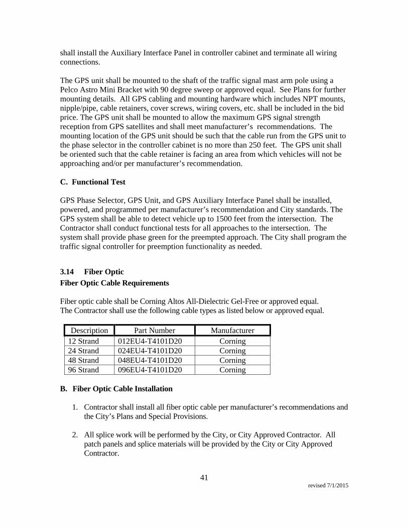
41 revised 7/1/2015
shall install the Auxiliary Interface Panel in controller cabinet and terminate all wiring connections. The GPS unit shall be mounted to the shaft of the traffic signal mast arm pole using a Pelco Astro Mini Bracket with 90 degree sweep or approved equal. See Plans for further mounting details. All GPS cabling and mounting hardware which includes NPT mounts, nipple/pipe, cable retainers, cover screws, wiring covers, etc. shall be included in the bid price. The GPS unit shall be mounted to allow the maximum GPS signal strength reception from GPS satellites and shall meet manufacturer’s recommendations. The mounting location of the GPS unit should be such that the cable run from the GPS unit to the phase selector in the controller cabinet is no more than 250 feet. The GPS unit shall be oriented such that the cable retainer is facing an area from which vehicles will not be approaching and/or per manufacturer’s recommendation. C. Functional Test GPS Phase Selector, GPS Unit, and GPS Auxiliary Interface Panel shall be installed, powered, and programmed per manufacturer’s recommendation and City standards. The GPS system shall be able to detect vehicle up to 1500 feet from the intersection. The Contractor shall conduct functional tests for all approaches to the intersection. The system shall provide phase green for the preempted approach. The City shall program the traffic signal controller for preemption functionality as needed.
3.14 Fiber Optic
Fiber Optic Cable Requirements Fiber optic cable shall be Corning Altos All-Dielectric Gel-Free or approved equal. The Contractor shall use the following cable types as listed below or approved equal.
Description Part Number Manufacturer 12 Strand 012EU4-T4101D20 Corning 24 Strand 024EU4-T4101D20 Corning 48 Strand 048EU4-T4101D20 Corning 96 Strand 096EU4-T4101D20 Corning
B. Fiber Optic Cable Installation
1. Contractor shall install all fiber optic cable per manufacturer’s recommendations and
the City’s Plans and Special Provisions.
2. All splice work will be performed by the City, or City Approved Contractor. All patch panels and splice materials will be provided by the City or City Approved Contractor.

42 revised 7/1/2015
3. The Contractor shall test all fiber optic cable spans after installation (Bare Fiber Testing). Testing results must be provided to the City Inspector. The City shall review test results and accept or reject the cable within 5 working days. If accepted by the City, and the Contractor shall submit a request to the City to perform splice work. If rejected, the Contractor shall replace the cable and retest.
4. The Contractor shall maintain a record of all sheath footage markings for each cable
span. Hard and soft copy of all records shall be provided to the City with test results along with the program to review the soft copy of the test results.
5. Existing fiber optic cable must be protected from damage. The Contractor shall
contact the City Inspector twenty four (24) hours prior to working near any existing city fiber optic cabling.
6. During installation the tensile force shall not exceed 600 lbs. The Contractor shall
use a break away swivel, or a slip-clutch capstan, set for less than 600 lbs. pulling tensile strength.
7. Fiber marking tags shall be installed on fiber optic cable in every pull box. The tags
shall be non-adhesive, Hellermann-tyton 4” fiber optic marker, part number CMFO4 or approved equal.
8. The Contractor shall install Arnco Bull Line Part #WP12LC (with trace wire) or
approved equal with the fiber optic cable. C. Fiber Optic Cable Testing (Bare Fiber Testing): All testing shall be performed according to the Telecommunications Industry Association (TIA) Technical Service Bulletin TSB-140, “Additional Guidelines for Field – Testing Length, Loss and Polarity of Optical Fiber Cabling Systems.”
1. The Contractor may test the fiber optic cable prior to installation, but must test fiber optic cable after installation.
2. The Contractor shall test all fibers in the cable.
3. A continuity test using a power meter shall be used for 12 strand cables less than 200
feet. Power reading shall be provided with test results.
4. The Contractor shall use both a power meter test for continuity and an optical time domain reflectometer (OTDR) to test all other cable spans greater than 12 strands and longer than 200 feet. Proof of Calibration of all fiber optic test equipment may be requested by the inspector at any time, and must be provided along with the test results.

43 revised 7/1/2015
5. The fiber cable shall meet or exceed ANSI/EIA/TIA – 568B.3 and the latest BICSI TDMM Standards.
6. Test Results shall include the following:
a. Total fiber length b. Individual fiber traces for complete fiber length c. Losses of all anomalies d. Wavelength tested and measurement directions e. Manufacturer, model number and serial number of test equipment f. Name, signature and company technician/engineer g. Test Equipment Calibration Certificate for all fiber test equipment h. Test Date
7. The Contractor shall provide the test results to the City Inspector. If fiber cable fails
to meet cable testing standards and are not approved by the City, the Contractor shall remove the failed fiber optic cable and replace with new fiber optic cable at no additional cost to the City. New fiber optic cable shall be tested according to cable testing requirements in these Special Provisions.
3.15 Foundations to be Abandoned
Foundations to be abandoned shall be in accordance with Section 34-8 of the Standard Specifications. The top part of the foundation, anchor bolts, and conduits shall be removed to a depth of two feet (2’) below the surface of sidewalk or unimproved ground. The resulting hole shall be backfilled with material equivalent to the surrounding material.
3.16 Inspection
Inspection shall be in accordance with Section 34-22 of the Standard Specifications and these Specifications.
3.17 Interconnect Cable
Interconnect Cable shall not be spliced. The Contractor shall tone interconnect to match pairs. The Contractor shall terminate traffic signal interconnect at all locations where DSL communication equipment is used as noted on the Plans. The signal interconnect shall be terminated using termination blocks and be terminated as follows:

44 revised 7/1/2015
Termination Block
DSL Link 1 Pair #
Interconnect Pair Color
Side of Block
Side of Block
Interconnect Pair Color
DSL Link 2 Pair #
1 Blue/White Left Right Blue/White 1 3 Orange/White Left Right Orange/White 3 2 Green/White Left Right Green/White 2 4 Brown/White Left Right Brown/White 4
Interconnect cable shall conform to the following specifications: 12 Twisted Pair Shielded Interconnect Cable - Interconnect cable shall conform to Rural Electrical Association (REA) Specifications: PE-22 for polyethylene insulated and jacketed telephone cable. The cable shall consist of 12 twisted pairs of No. 19 solid copper conductors with an overall shield. Prior to delivery of the cable, Contractor shall furnish the Engineer a certified report of the tests made on the cable to show compliance with the above mentioned specification. Each end of the cable shall be properly sealed against moisture intrusion and shall be protected against injury. a. Cable Installation - The cable shall be installed as shown on the Plans and only under
dry conditions. The cable shall only be spliced at the locations shown on the Plans. A minimum of five feet (5') of slack cable shall be left coiled in each pull box. The ends of all cables shall be taped and made waterproof by dipping in an approved sealer prior to being installed in conduit and prior to being left overnight.
Unless otherwise specified by the Engineer, field terminations of interconnect cable
in the controller cabinets will be made by Contractor to provide a fully functional system.
b. Cable Testing After Installation - The interconnect cable shall be installed and ready
for cable testing (as specified below, 20 working days prior to anticipated use of said cable).
Each insulated conductor in each length of completed cable, with all other insulated
conductors grounded and shield grounded, shall have an insulation resistance of not less than:
Cable Lengths 500 Ft. 1000 Ft. 1500 Ft. 2000 Ft. Megohms 500 250 160 125
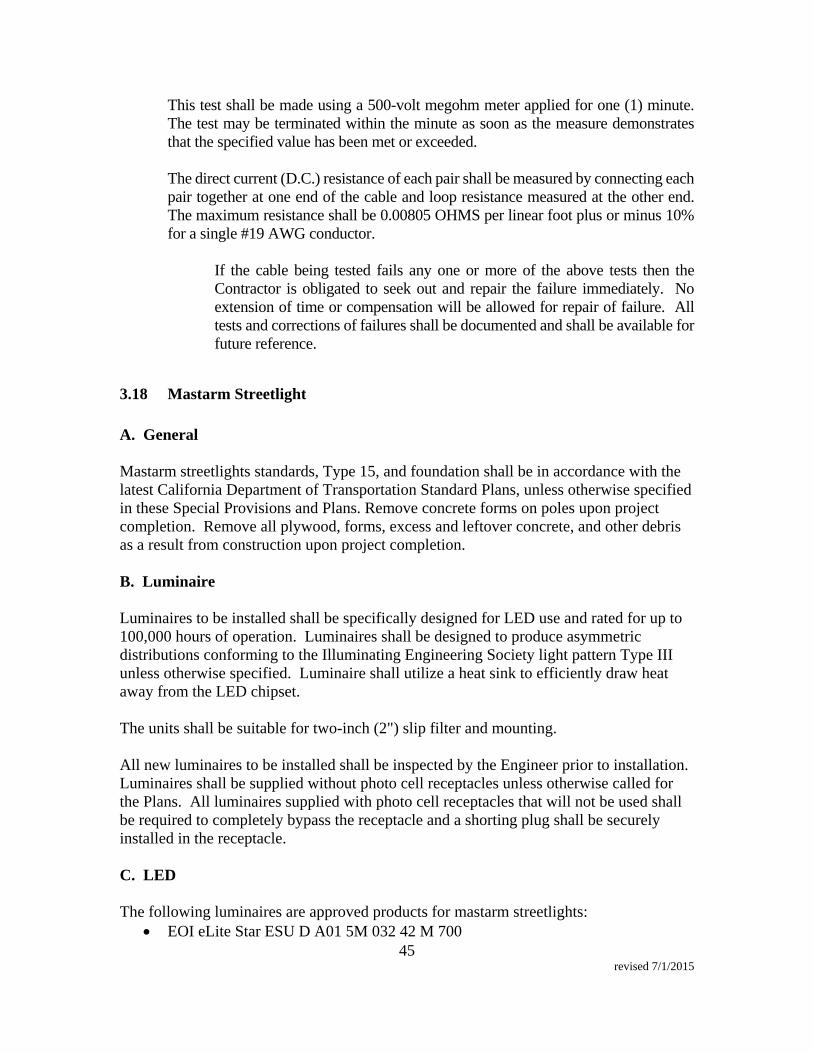
45 revised 7/1/2015
This test shall be made using a 500-volt megohm meter applied for one (1) minute. The test may be terminated within the minute as soon as the measure demonstrates that the specified value has been met or exceeded.
The direct current (D.C.) resistance of each pair shall be measured by connecting each
pair together at one end of the cable and loop resistance measured at the other end. The maximum resistance shall be 0.00805 OHMS per linear foot plus or minus 10% for a single #19 AWG conductor.
If the cable being tested fails any one or more of the above tests then the
Contractor is obligated to seek out and repair the failure immediately. No extension of time or compensation will be allowed for repair of failure. All tests and corrections of failures shall be documented and shall be available for future reference.
3.18 Mastarm Streetlight
A. General Mastarm streetlights standards, Type 15, and foundation shall be in accordance with the latest California Department of Transportation Standard Plans, unless otherwise specified in these Special Provisions and Plans. Remove concrete forms on poles upon project completion. Remove all plywood, forms, excess and leftover concrete, and other debris as a result from construction upon project completion. B. Luminaire Luminaires to be installed shall be specifically designed for LED use and rated for up to 100,000 hours of operation. Luminaires shall be designed to produce asymmetric distributions conforming to the Illuminating Engineering Society light pattern Type III unless otherwise specified. Luminaire shall utilize a heat sink to efficiently draw heat away from the LED chipset. The units shall be suitable for two-inch (2") slip filter and mounting. All new luminaires to be installed shall be inspected by the Engineer prior to installation. Luminaires shall be supplied without photo cell receptacles unless otherwise called for the Plans. All luminaires supplied with photo cell receptacles that will not be used shall be required to completely bypass the receptacle and a shorting plug shall be securely installed in the receptacle. C. LED The following luminaires are approved products for mastarm streetlights:
EOI eLite Star ESU D A01 5M 032 42 M 700
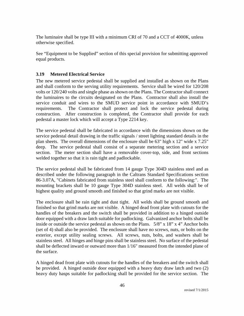
46 revised 7/1/2015
The luminaire shall be type III with a minimum CRI of 70 and a CCT of 4000K, unless otherwise specified. See “Equipment to be Supplied” section of this special provision for submitting approved equal products.
3.19 Metered Electrical Service
The new metered service pedestal shall be supplied and installed as shown on the Plans and shall conform to the serving utility requirements. Service shall be wired for 120/208 volts or 120/240 volts and single phase as shown on the Plans. The Contractor shall connect the luminaires to the circuits designated on the Plans. Contractor shall also install the service conduit and wires to the SMUD service point in accordance with SMUD’s requirements. The Contractor shall protect and lock the service pedestal during construction. After construction is completed, the Contractor shall provide for each pedestal a master lock which will accept a Type 2214 key. The service pedestal shall be fabricated in accordance with the dimensions shown on the service pedestal detail drawing in the traffic signals / street lighting standard details in the plan sheets. The overall dimensions of the enclosure shall be 63" high x 12" wide x 7.25" deep. The service pedestal shall consist of a separate metering section and a service section. The meter section shall have a removable cover-top, side, and front sections welded together so that it is rain tight and padlockable. The service pedestal shall be fabricated from 14 gauge Type 304D stainless steel and as described under the following paragraph in the Caltrans Standard Specifications section 86-3.07A, "Cabinets fabricated from stainless steel shall conform to the following:". The mounting brackets shall be 10 gauge Type 304D stainless steel. All welds shall be of highest quality and ground smooth and finished so that grind marks are not visible. The enclosure shall be rain tight and dust tight. All welds shall be ground smooth and finished so that grind marks are not visible. A hinged dead front plate with cutouts for the handles of the breakers and the switch shall be provided in addition to a hinged outside door equipped with a draw latch suitable for padlocking. Galvanized anchor bolts shall be inside or outside the service pedestal as shown on the Plans. 5/8” x 18” x 4” Anchor bolts (set of 4) shall also be provided. The enclosure shall have no screws, nuts, or bolts on the exterior, except utility sealing screws. All screws, nuts, bolts, and washers shall be stainless steel. All hinges and hinge pins shall be stainless steel. No surface of the pedestal shall be deflected inward or outward more than 1/16" measured from the intended plane of the surface. A hinged dead front plate with cutouts for the handles of the breakers and the switch shall be provided. A hinged outside door equipped with a heavy duty draw latch and two (2) heavy duty hasps suitable for padlocking shall be provided for the service section. The
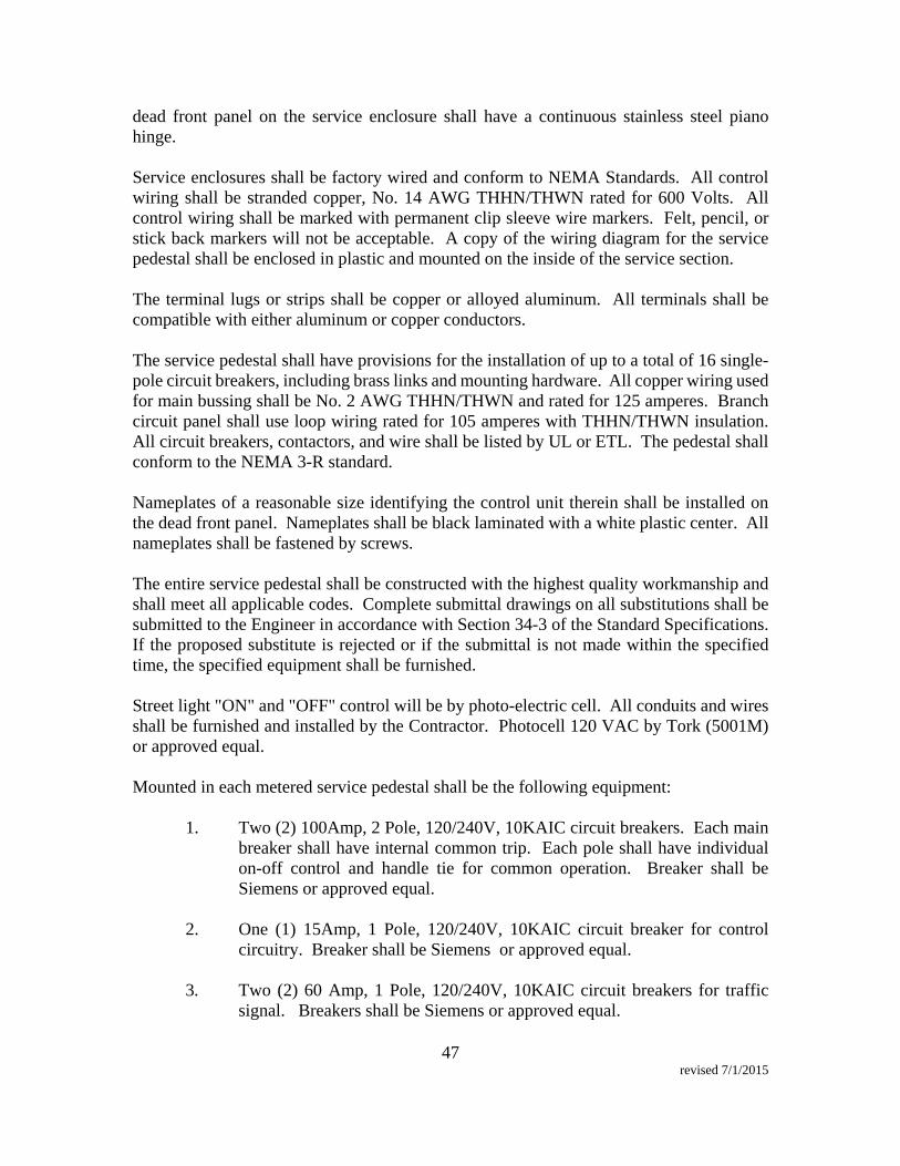
47 revised 7/1/2015
dead front panel on the service enclosure shall have a continuous stainless steel piano hinge. Service enclosures shall be factory wired and conform to NEMA Standards. All control wiring shall be stranded copper, No. 14 AWG THHN/THWN rated for 600 Volts. All control wiring shall be marked with permanent clip sleeve wire markers. Felt, pencil, or stick back markers will not be acceptable. A copy of the wiring diagram for the service pedestal shall be enclosed in plastic and mounted on the inside of the service section. The terminal lugs or strips shall be copper or alloyed aluminum. All terminals shall be compatible with either aluminum or copper conductors. The service pedestal shall have provisions for the installation of up to a total of 16 single-pole circuit breakers, including brass links and mounting hardware. All copper wiring used for main bussing shall be No. 2 AWG THHN/THWN and rated for 125 amperes. Branch circuit panel shall use loop wiring rated for 105 amperes with THHN/THWN insulation. All circuit breakers, contactors, and wire shall be listed by UL or ETL. The pedestal shall conform to the NEMA 3-R standard. Nameplates of a reasonable size identifying the control unit therein shall be installed on the dead front panel. Nameplates shall be black laminated with a white plastic center. All nameplates shall be fastened by screws. The entire service pedestal shall be constructed with the highest quality workmanship and shall meet all applicable codes. Complete submittal drawings on all substitutions shall be submitted to the Engineer in accordance with Section 34-3 of the Standard Specifications. If the proposed substitute is rejected or if the submittal is not made within the specified time, the specified equipment shall be furnished. Street light "ON" and "OFF" control will be by photo-electric cell. All conduits and wires shall be furnished and installed by the Contractor. Photocell 120 VAC by Tork (5001M) or approved equal. Mounted in each metered service pedestal shall be the following equipment:
1. Two (2) 100Amp, 2 Pole, 120/240V, 10KAIC circuit breakers. Each main
breaker shall have internal common trip. Each pole shall have individual on-off control and handle tie for common operation. Breaker shall be Siemens or approved equal.
2. One (1) 15Amp, 1 Pole, 120/240V, 10KAIC circuit breaker for control
circuitry. Breaker shall be Siemens or approved equal. 3. Two (2) 60 Amp, 1 Pole, 120/240V, 10KAIC circuit breakers for traffic
signal. Breakers shall be Siemens or approved equal.
48 revised 7/1/2015
4. Six (6) 40 Amp, 1 Pole, 120/240V, 10KAIC circuit breakers for street lighting. Breakers shall be Siemens or approved equal.
6. Two (2) 60 Amp, 3-pole, 120/240V contactors. Normally open, mercury
contactors. Contactors shall be Durakool, or approved equal. 7. One oil tight "Hand-Off-Auto" selector switch. 8. One solid copper neutral bus. 9. Incoming terminals (landing lugs). 10. Solid neutral terminal strip. 11 Terminal strips for conductors within the cabinet.
3.20 Microwave Detection System Details
General Requirements: Microwave detection system shall accurately detect vehicle volume, headway, gap, occupancy, presence, speed and 85 percentile speed for up to 10 traffic lanes simultaneously. The system shall be designed for rapid installation and shall be remotely configurable. The installation of the system shall be according to the manufacturer’s procedures. All data transmission cable shall be continuous and access through Ethernet network connection. All connections shall be made at the designated connectors. No splicing shall be allowed in conduits, pullboxes, or poles. The system shall have a warrantee for a minimum of two years from activation. The system shall be Wavetronix Smartsensor HD 125, or approved equal. The system general requirements are as follows: Model Number: 125 Operating Frequency: 24.0 to 24.25 GHz (K-band) Detection Method: Frequency Modulated Continuous Wave Radar Zone Resolution: 1 foot (0.3m) Time Resolution: 2 msec Communications: RS-232 and RS-485 connection Power: 8 watts @ 9-36 VDC Operating Temperature: -40F to 165F The system shall consist of two subsystems, the sensors and the controller cabinet unit.
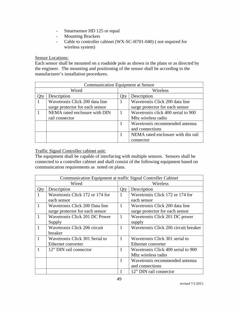
49 revised 7/1/2015
- Smartsensor HD 125 or equal - Mounting Brackets - Cable to controller cabinet (WX-SC-H701-040) ( not required for
wireless system) Sensor Locations: Each sensor shall be mounted on a roadside pole as shown in the plans or as directed by the engineer. The mounting and positioning of the sensor shall be according to the manufacturer’s installation procedures.
Communication Equipment at Sensor Wired Wireless
Qty Description Qty Description 1 Wavetronix Click 200 data line
surge protector for each sensor 1 Wavetronix Click 200 data line
surge protector for each sensor 1 NEMA rated enclosure with DIN
rail connector 1 Wavetronix click 400 serial to 900
Mhz wireless radio 1 Wavetronix recommended antenna
and connections 1 NEMA rated enclosure with din rail
connector Traffic Signal Controller cabinet unit: The equipment shall be capable of interfacing with multiple sensors. Sensors shall be connected to a controller cabinet and shall consist of the following equipment based on communication requirements as noted on plans.
Communication Equipment at traffic Signal Controller Cabinet Wired Wireless
Qty Description Qty Description 1 Wavetronix Click 172 or 174 for
each sensor 1 Wavetronix Click 172 or 174 for
each sensor 1 Wavetronix Click 200 Data line
surge protector for each sensor 1 Wavetronix Click 200 data line
surge protector for each sensor 1 Wavetronix Click 201 DC Power
Supply 1 Wavetronix Click 201 DC power
supply 1 Wavetronix Click 206 circuit
breaker 1 Wavetronix Click 206 circuit breaker
1 Wavetronix Click 301 Serial to Ethernet converter
1 Wavetronix Click 301 serial to Ethernet converter
1 12” DIN rail connector 1 Wavetronix Click 400 serial to 900 Mhz wireless radio
1 Wavetronix recommended antenna and connections
1 12” DIN rail connector
50 revised 7/1/2015
Wiring: For home runs that are less than 300’ use Alpha 6033-C3, pair separately shielded 20 awg cable or approved equal. For home runs that are over 300’, but less than 1000’, use Alpha 6023-C3, pair separately shielded 18 awg cable or approved equal.
3.21 Ornamental Streetlight
A. Streetlight Assembly The streetlight manufacturer shall provide all required components to assemble a streetlight as shown in the attached drawing and as described in the following Special Provisions. The manufacturer shall guarantee that all components provided, when assembled, shall constitute a complete functioning streetlight. The streetlight capital, globe holder, light engine base, fluted shaft, and base shall be delivered as a single unit, fully assembled and painted as describe in the following Special Provisions. The luminaire assembly, Light Emitting Diode (LED) light engine, and anchor bolts, if required, may be delivered in a separate shipment or container. Optionally, streetlight assembly shall have weatherproof UL listed GFI electrical receptacles mounted at the top of the pole shaft. The complete streetlight assembly and anchor bolts shall be delivered to a location in the metropolitan area of Sacramento, California, as specified by the City. The City will provide the manufacturer the delivery destination within two weeks prior to the delivery date, unless otherwise specified by the City. B. Luminaire Assembly The luminaire assembly shall include a 424 Lexalite Acrylic Prismatic Top, GE8-9 globe, Formed Plastic FP 199, or National Lighting NL199 globe or approved equal as shown on the drawing. The luminaire assembly shall be UL listed for wet/damp locations and shall be furnished prewired. The Lexalite 424 globe shall have IES Distribution Type III or V as specified by the City Engineer. Assembly of top and bottom parts of the globe shall be by a stainless steel band. Globe top shall not include a factory installed Lexalite spike aluminum finial. The globe shall be provided with a neck ring so that the tightening of the screws will not damage the globe collar. Unless otherwise specified, the lamp assembly shall be delivered with a light engine. The light engine shall be of LED manufactured by PEMCO model PT-45, or approved equal.

51 revised 7/1/2015
C. Cast Iron Capital and Globe Holder The capital and globe holder shall be of the design and dimensions as shown on the drawing and shall be of cast iron per ASTM A48 CL30 standards. The globe holder shall have four (4) 5/16” stainless steel set screws (90 degrees) for mounting of the globe. Set screws shall be square head. Allen or Phillips set screws are not acceptable. The capital shall be prewired with a light engine base. The light engine base shall be of porcelain mogul type. The capital shall be attached to a 4” tenon mounted on top of the steel fluted shaft with four (4) 5/16” stainless steel screws. D. Steel Fluted Shaft The fluted shaft shall be of the dimensions shown on the drawing and shall be tapered 0.14” per foot. The fluted shaft shall have the chemical and physical properties of A595 grade A. The fluted shaft shall be fabricated from a single length of a minimum 11-gauge steel sheet, rolled into a fluted shaft on a steel mandrill and finished with a single longitudinal weld. No transverse or intermediate welds or joints shall be permitted. The fluted shaft shall have sixteen (16) equally spaced Doric flutes, sharp and clear-cut throughout the entire length of the shaft. The radius of the flute's crest shall not exceed the thickness of the shaft material. Individually rolled flutes or round poles with a separate fluted sheathing are not acceptable. Shaft shall be formed true to the pattern and complete in detail. The interior surface shall be smooth with no protrusions or sharp edges. There shall be a minimum of 2” internal clearance extending the fluted shaft’s length to permit internal wiring from an underground source. At the top of the fluted shaft, a steel tenon shall be welded and sized to accept the capital and globe holder. The maximum difference in the diameter of the capital and the tenon shall be ½”. A ½” steel adapter plate, of 36,000 psi minimum yield strength, shall be welded to the bottom of the fluted shaft. The adapter plate shall include three (3) tapped holes on a 4” bolt-circle to accept ½” -13 stainless steel bolts for attachment to the streetlight pole base. The stainless steel bolts shall be per ASTM F593. The bolts shall be with a minimum yield strength of 92,000 psi. The maximum diameter offset between the bottom of the fluted shaft and the adapter plate shall be as shown in the drawing. All welds shall meet AWS D1.1. The complete fluted shaft shall be hot-dipped galvanized per ASTM A123 prior to painting. E. Cast Iron Base The streetlight base shall be of the design and dimensions as shown on the drawing and shall be of cast iron per ASTM A48 CL30 standards with a minimum thickness of ½”.

52 revised 7/1/2015
The base shall have an opening for the hand hole of the dimensions shown on the drawing with the cover cast of the same material, and attached with a ½” stainless steel, button head hex socket cap screw. The base shall have three (3) holes integrally cast into its top to be attached to the shaft. A minimum of 2” wiring access hole shall also be provided. The base shall be furnished with a 12”-13 UNC grounding bolt. The base shall have four (4) reinforced lugs integrally cast into its bottom to accept ¾” anchor bolts on a 15” bolt-circle. F. Anchor Bolts Unless otherwise specified, each streetlight assembly shall include four (4) galvanized steel anchor bolts of the dimensions as shown on the drawing. Anchor bolts shall meet ASTM – A36 with 55,000 psi minimum yield strength. The threaded portion shall be galvanized. Each anchor bolt shall include two (2) galvanized hex nuts and two (2) flat washers. All galvanized parts shall meet ASTM A153. G. Surface Coating The exterior and interior surfaces of the streetlight base, fluted shaft, and capital shall have surface preparation, primer coating, and two coats of paint. The surfaces of the base, fluted shaft, and capital shall have a smooth finish that shall be uniform along the entire length of the streetlight pole assembly. All surface preparation, primer coating, and painting application shall be performed inside a shop or plant before shipment to jobsite.
The manufacturer shall provide Manufacturer Certification that all primer coating and paint application was performed per coating manufacturer specifications for the selected coating, prior to delivery of streetlight pole. Minor field coating touch-up may be permitted at the City’s discretion. All work shall be performed in strict accordance with these specifications and the manufacturer's directions for the materials to be used on this project.
1. Surface Preparation The exterior and interior surfaces of the pole shall be prepared as follows:
a) All sharp edges shall be removed or rounded. b) Contaminants such as oil, grease, dirt, etc., shall be removed by solvent
cleaning per SSPC-SP1 (solvent cleaning). c) All non-galvanized surfaces shall be blasted per SSPC-SP10 (Near White
Metal Blast) to remove all rust, mill scales, slags, and foreign matters.

53 revised 7/1/2015
d) Streetlight base, fluted shaft, and capital shall be primed on the same day the surface preparation is completed.
2. Primer Coating After surface preparation is completed, the cast iron streetlight assembly shall have a primer coating as follows:
a) Use Sherwin Williams Macropoxy 646 Fast Cure Epoxy - Black (OR Mill
White primer if Sacramento Green is specified as the paint color) or approved equal.
b) Mix Macropoxy per manufacturer directions. c) Apply primer to the entire streetlight assembly, including the interior and
exterior surfaces. d) Apply a fog coat of primer of 1.0 - 2.0 mils, approximately 1 hour prior to
full prime coat. e) Apply full prime coat at the recommended spreading rate per coat for the
Macropoxy 646 Primer; wet mills (7 minimum, 13.5 Maximum), dry Mills (5 minimum, 10.0 Maximum). See manufacturer product information for drying schedule and application conditions.
3. Paint Application After primer coating, the streetlight assembly shall be painted as follows:
a) Use Sherwin Williams Hi-Solids Polyurethane 100 - Gloss Black (OR
Sacramento green color if specified on the drawing) or approved equal. b) Apply two (2) coats of paint to the entire streetlight assembly, including the
interior and exterior surfaces. c) Apply the paint at the recommended film thickness and spreading rate per
coat; wet mills 3.6 minimum, 4.8 maximum; dry mills 3.0 minimum, 4.0 maximum. See manufacturer product information for drying schedule and application conditions.
Paint application shall be in accordance with the principles of good workmanship described in SSPC-PA1, Paint Application Specification No. 1, Shop Field and Maintenance Painting. The Quality Control/Specifications are as follows: Dry Film test per ASTM D7378-07, Holiday Porosity Test per ASTM D5162-01, Cross Hatch Adhesion per ASTM D6677-01, Pencil Hardness test per ASTM D3363, Impact Resistance per ASTM D2794, Visual Gloss Inspection, and Final Visual Inspection. H. Design Standards Streetlight assembly and all materials used in its manufacture shall meet the requirements of the most current adopted version of the American Association of State Highway and

54 revised 7/1/2015
Transportation Officials (AASHTO) “Standard Specifications for Structural Supports for Highway Signs, Luminaires and Traffic Signals” and this specification. In addition to the requirements of the AASHTO Specification, the post and anchorage shall be designed with a minimum safety factor of two (2) and shall not deflect more than five (5%) percent of the above ground height at full wind loading. I. Factory Certification Each streetlight assembly shall be certified by the manufacturer to meet all requirements specified herein. The manufacturer shall make factory and all manufacturing processes open for City Quality Control Inspection if requested by the City Engineer. City shall incur all inspection cost. J. Identification Each pole shall bear an identification tag which shall list the manufacturer model number of the pole and year and location of manufacture. The identification tag shall be placed inside of the base, facing the hand hole, and clearly visible from the outside when installed and the hand hole cover is removed. K. Material Availability Pole manufacturer shall certify to the City that the accepted pole base, capital, shaft, and luminaire is or will become a stock item, readily available with replacement parts for a minimum ten (10) year. L. Material Certification Material certifications shall be provided for all components referred to in the drawing and these Special Provisions. M. Packaging Each streetlight assembly and luminaire shall be individually packaged to prevent damage with sufficient packaging strength for protection during shipping and storage. Small parts shall be packaged in boxes. Individual components shall be packaged in the same manner as the poles and luminaries. All handling shall be done with rope or nylon slings to prevent surface damage. Use of chains, wire slings or unprotected forks or hooks is prohibited. Packing list and assembly instruction sheet shall be included.

55 revised 7/1/2015
N. Acceptance After packaging is removed and prior to installation, each streetlight assembly shall be inspected for manufacturing or paint defects by the City Engineer. No streetlight assembly is to be installed without the expressed approval of the City. O. Testing Factory testing shall be provided at the request of the City Engineer in accordance with manufacturer's testing procedures. P. Warranty The streetlight manufacturer shall warrant against any defects and shall replace all defective parts or streetlight assemblies for a period of five (5) years from the date received by the City. Pole manufacturer shall provide written warranty with shipment of poles. Q. Welding Welding shall be conducted by certified welders in compliance with the latest edition of the American Welding Society D1.1, Structural Welding Code - Steel. All parts shall be cleaned prior to welding by an approved industry standard method. R. Wind Resistance Entire pole and luminaire to be rated to withstand AASHTO requirements for a minimum 70 mile and hour wind load with a 30% gust factor. S. Sealing of Streetlight Pole Foundation The concrete for the foundation shall be finished so that the top surface is straight and smooth with a 2% grade conforming to the adjoining sidewalk. Remove concrete forms on streetlight foundation upon project completion. Remove all plywood, forms, excess and leftover concrete, and other debris as a result from construction upon project completion. Once the pole is installed and leveled on the anchor bolts, the gap between the base of the pole and the top of the foundation shall be sealed using the following procedure: The bottom surface of the pole base shall be primed using Pecora P-120 or approved equal and the top of the foundation shall be primed using a Pecora P-150 or approved equal. The curing of the concrete used for the foundation or pavement and the application of the primer shall follow the guidelines provided by the manufacturer of the primer and sealant.

56 revised 7/1/2015
The gap to be sealed shall be partially filled by pushing in a 1.5” diameter Bi-Cellular Backer Rod (SOF Rod), cut to size, and installed around the bottom perimeter of the pole base, pushed against the anchor bolts. The backer road product shall be made by Construction Foam Products or approved equal. A one half-inch (1/2”) inside diameter drain tube shall be placed in the gap between the base of the pole and its foundation to prevent standing water. The drain tube shall be placed under the backer rod, flush with the finished surface of the concrete, and extending about 2.25” toward the center of the pole base. It shall be placed so that it is following the downward slope of the surrounding sidewalk and top of foundation (about 2%). The drain tube shall be made of PVC with a wall thickness of 1/16” or as approved by the engineer. Once the primer is dry as recommended by the manufacturer, and the backer rod is installed, the Contractor shall apply a silicone sealant, with a minimum thickness of 0.5inch. Use a pre-tinted black color silicone, model number Pecora 890NST or approved equal. Completely seal the gap between the base of the pole and the top of the foundation with the silicone sealant. Use a masking tape when applying the sealant, in order not to smear the outside of the pole, and the surrounding pavement with the sealant material. The sealant shall be smoothed out around the base of the pole, and any excess material removed before it is set to cure as required by the sealant manufacturer. The sealant shall be smoothed out around the base of the pole, and any excess material removed before it is set to cure as required by the sealant manufacturer.

57 revised 7/1/2015
3.22 Post Top Luminaires
A. General Post top streetlights shall be in accordance with the latest City of Sacramento Standard Specifications, unless otherwise specified in these Special Provisions or Plans. All post top streetlights shall have an LED light engine. B. Specifications for Luminaire The LED light fixture shall be Acquitybrands Contempo LED Series 245L – 20LEDE70-MVOLT-4K-R3-RNA-NR or approved equal. Hood Style A and Gray finish, as shown in the Acquitybrands Contempo LED Series 245L. No photocontrol receptacle. The post top streetlight standard and luminaire shall conform to the following:
1) LED light engine. 44 input watts. 2) Multi-voltage driver. 120-277 volts. 3) Color Temperature. 4000K. 4) Type III distribution. 5) Acrylic Rain Panel. 6) Paint: Grey exterior finish. 7) Luminaire canopy shall be 22 inches in diameter. 8) Luminaire height shall be 20 inches in diameter. 9) LED light engine greater than 100,000 hours at 25 degree C. 10) CSA listed and suitable for up to 30 degree C. 11) Complies with ANSI: C136.2, C136.10, C136.15 12) Cone mounting fitter with three set screws to install to pole tenon. 3” diameter
pole tenon. Set screws shall be hex or square head screws. Slotted or Allen set screws are not acceptable.
13) Hinged hood and captive screw latching. 14) Multi-gasketing to provide weatherproof protection of assembly. 15) Die-cast aluminum housing and spun aluminum hood. 16) All external hardware shall be stainless steel or other corrosion resistant metal.
C. Specification for Pole and Foundation The post top pole, anchor bolt configuration, and foundation specifications and details are shown in the latest City of Sacramento Standards, page E-90. Remove concrete forms on streetlight poles upon project completion. Remove all plywood, forms, excess and leftover concrete, and other debris as a result from construction upon project completion.
58 revised 7/1/2015
3.23 Pull Boxes
Shall be in accordance with Section 34-11 of the Standard Specifications, except for the following:
a. All new pull boxes shall be set in place prior to pouring any new sidewalk. b. Existing pull boxes damaged by the installation of new conduits shall be removed and
replaced at the Contractor's expense as directed by the Engineer. c. All pull boxes shall be placed in sidewalk areas unless otherwise specified on the plans
or directed by the Engineer, and shall not be placed in driveways, in vehicular traveled lanes, or in any part of the new sidewalk handicap ramp areas. Unless otherwise specified, pull boxes shall be placed a minimum of 5 feet from existing driveways.
d. Contractor shall cut, remove and replace the concrete to the nearest joint when
installing new pull boxes. e. New pull boxes shall have a minimum of 6” of new concrete around all sides in
sidewalks. f. For pull boxes to be removed, holes or depressions resulting from the removed pull
box shall be filled, compacted, brought to grade, and filled to match surrounding materials.
g. Pull boxes shall be placed as shown according to the details shown on the Plans and
according to these Special Provisions.
h. Install pull box on top of crushed rock foundation. Adjust pull box to grade. The crushed rock foundation shall have a minimum of 12” in depth and continue to extend a minimum of 6” beyond the outside edge of the pull box. Compact crushed rock while maintaining integrity of conduit. Conduit and pull boxes shall not be damaged nor cracked.
i. In instances where the pull box is installed in a planter box or dirt areas, the pull box shall be set to grade with a concrete ring, as shown in the standard detail drawings.
j. Locking Pull Box Security Lids 1) No locking Security Lids shall be use on Pull Boxes containing traffic signal
wiring. 2) All No. 5 and No. 6 Pull Boxes containing street light wiring shall have steel
security lids with locking key bolts. 3) Security Bolts shall be Bryce Fastener #50 Penta-Plus approved equal. 4) Security Keys shall be Bryce Fastener 1GBP50 or approved equal. 5) Lid shall be ¼” thick minimum galvanized steel. 6) Lid shall be manufactured with slip resistant surface.

59 revised 7/1/2015
7) Lid shall be non-traffic rated, unless otherwise specified. 8) Lid shall be equipped with a lock mechanism which can be secured from the top
of lid. 9) Lock bolt shall be recessed in 1 inch diameter circle 10) Lid shall be flush with top of pull box when the lid is completely secured and
locked to the pull box. 11) No. 5 pull boxes shall have a single cam locking system, or approved equal. 12) No. 6 pull boxes shall have a double cam locking system, or approved equal. 13) Lid shall have a grounding lug. 14) Supply five sets of keys for the locks. 15) Supply two sets of lifting tools for the lid. 16) Lid shall be free of scratches, defects, and debris. Provided Lids shall be
installed new. 17) Pull Box Lid shall be manufactured by LockLid Secure Utility Enclosure Lids
manufactured by Jensen MetalTech or approved equal. o #5 PB - Locklid 1324 Lid LL K-S TrxPlt Sac Glv; o #6 PB – LockLid 1730 Lid LL K-SD TrxPlt Sac Glv). o #5 PB Sipra Corp’s Lockjaw! Security lids model## o #6 PB Sipra Corp’s Lockjaw! Security lids model## o #5 PB WESCO’s Mr. Steel Security Security lids model## o #6 PB WESCO’s Mr. Steel Security Security lids model##
18) A steel welding plug shall be provided by the manufacturer to be inserted into the 1 inch diameter recessed lock
3.24 Traffic Signals and Fittings
Traffic Signal Standards and Lighting Standards shall be in accordance with the latest California Department of Transportation Standard Plans, unless otherwise specified in these Specifications or Plans. A. Forms and Concrete and Debris Remove concrete forms on traffic signal standards and service pedestals upon project completion. Remove all plywood, forms, excess and leftover concrete, and other debris as a result from construction upon project completion. B. Vehicle Signals
All signal heads, louvers, backplates, and framework shall come in black color. Each mast arm mounted signal head shall be all 12" diameter sections. Vehicle signal housings shall be either die cast or permanent mold cast aluminum conforming to ANSI Standard D-10.1. Vehicle signal faces shall conform to Section 86-4.01, "Vehicle Signal Faces", of the State Standard Specifications.

60 revised 7/1/2015
Metal backplates shall be provided for all vehicle signal heads furnished. Backplates shall be louvered, not solid. Traffic signals shall utilize tunnel visors. All traffic signal lamps shall be accessible from the front of the traffic signal head and shall be directly accessible for removal and replacement by the opening of the hinged front lens section and hood. Backplates for MAS mounted vehicle signal heads shall have approved filler plates to prevent light from showing through at the elevated plumbizers.
C. Light Emitting Diode (LED) Signal Modules
ALL SIGNAL HEAD DISPLAYS SHALL BE LED MODULES. LEDs shall have full ball appearance. Dialite 443 Series or approved equal. Maximum power consumption requirements for LED signal modules shall be as follows:
Description 25°C 74°C 12” Circular 25.0 W 30.0 W 12” Arrow 15.0 W 18.0 W
All LED modules shall meet California Department of Transportation (CalTrans) and Institute of Traffic Engineer (ITE) minimum requirements. CalTrans specifications shall take precedence and supercede all ITE requirements if there are requirement conflicts.
D. Pedestrian Signals
All pedestrian display shall be the combination Raised Hand/Walking Person figure and Countdown timer only. All pedestrian heads and framework shall come in black color. Pedestrian signal face modules shall be designed to mount behind or replace the existing faceplate of Type A Pedestrian housings as specified by the requirements of the ITE Standards, “Pedestrian Traffic Control Signal Indications”, and the MUTCD. The pedestrian signal shall have an operating range of 80VAC to 135VAC. The pedestrian signal shall be fused and provide transient suppression for protection of line and load. The pedestrian signal shall have a high power factor > 0.9. The pedestrian signal shall have < 20% harmonic distortion. The design of the modules shall require a specific mounting orientation. Each module shall provide an average luminous intensity of at least 3,750 candela/m2 for

61 revised 7/1/2015
Upraised hand and 5,300 candela/m2 for the Walking person symbol throughout the useful life over the operating temperature range. The uniformity ratio of an illuminated symbol shall not exceed 4 to 1 between the highest luminance area and the lowest luminance area in the module. The color output of the module shall conform to the requirements of the ITE: ”Pedestrian Traffic Control Signal Indications” and the MUTCD. The Hand Man symbols shall conform to all applicable ITE and CalTrans requirements. Raised Hand shall be Portland orange. Walking figure shall be lunar white. The module shall not require special tools for installation. The module shall fit securely into existing pedestrian signal section housings built to the PTCSH specifications without modification to the housing. The pedestrian signal face shall be no less than 16” high. Aluminum housing. The modules shall be a self-contained device, not requiring on-site assembly for installation into an existing Type "A" housing. The pedestrian signal shall be capable of displaying the LED “Raised Hand” legend. The numeral portion shall consist of two (2) seven segment digits, constructed of a minimum of 2 rows of LED’s, simultaneously. The pedestrian signal shall use overlays to diffuse the LED's and provide uniform light dispersion while keeping the symbols clear and distinct. The signal shall be configurable, such that the countdown timer can start at the beginning or the end of the “Walk” portion of the pedestrian phase. Initially, the Contractor shall set the signal such that the Countdown timer starts at the beginning of the flashing “Don’t Walk/Raised Hand” portion of the phase and ends at the beginning of the solid “Don’t Walk/Raised Hand” portion of the phase. Modules shall have filled hand/man.
E. Mounting Hardware All slipfitters and terminal compartments shall be cast bronze. Clam shell mounting
assemblies shall not be used. F. Pedestrian Pushbuttons The pedestrian pushbuttons shall conform to Section 86-5.02, "Pedestrian
Pushbuttons", of the State Specifications and these Specifications. Pedestrian pushbuttons shall be Type B and meet all American Disability Act (ADA) requirements. The diameter of the actuator shall be 2-inch minimum.
The pedestrian pushbuttons shall be magnetic switch type pushbuttons in heavy cast
aluminum or highly durable corrosion-proof housings. The buttons shall be a high visibility yellow. The instruction sign shall be a minimum 20 gauge enameled steel,

62 revised 7/1/2015
5" x 7-3/4" and shall display the appropriate sign for international symbol signals. The mounting height of the pedestrian push button shall be as specified in the latest CalTrans Specifications. Frame shall be black.
G. Traffic Signal Standards All mounting hardware to be furnished by the Contractor shall be galvanized. H. Battery Back-Up System (BBS)
Contractor shall provide and install the Battery Back-Up System if specified on the planset. The Battery Back-Up System shall comply with the latest California Department of Transportation specifications and requirements. The BBS shall be in complete compliance with City of Sacramento NEMA controllers and cabinets. The battery back-up unit and batteries shall be contained in a separate cabinet. Clarey Model SP1000SN (Plus) or equal. BBS shall only be provided and installed if specified in the plans.
I. Accessible Pedestrian Signal (APS)
The Accessible Pedestrian Signal (APS) shall be manufactured by Polara Engineering, Inc (Model: EZ Communicator 2 Wire Navigator APS). APS shall be installed in accordance with the City of Sacramento’s APS Implementation Guidelines. The APS consists of three primary components: Pedestrian Interface Units, a Control Unit, and a System Programmer. 1) Pedestrian Interface Unit:
a. A Pedestrian Interface Unit (PIU) receives pedestrian crossing requests and provides visual, audio, and speech pedestrian messages to aid street crossing. The PIU shall be installed per the latest requirements of the California MUTCD. The PIU shall be suitable for installation on a typical pedestrian signal pole with no special tools required. Where pedestrian clearance time is such that pedestrians must wait at a median, a PIU may be provided in the median so long as median meets the minimum accessibility requirements. The PIU shall be constructed of cast aluminum or equal, painted with yellow background, black crossing logo, a tactile arrow indicating the direction of crossing it services, and an integrated two-inch diameter pushbutton. The pushbutton shall be of cast aluminum, painted yellow, rated at 100 million activations minimum at up to 2 lbs force. When these features are activated, the PIU shall confirm each pushbutton activation by visual, audio, and vibrotactile feedback. Visual messsages shall be by high intensity LED at 1200 mcd minimum, with 160 degree visibility cone.

63 revised 7/1/2015
b. Audio messages shall be via integrated, sealed, and weatherproof speakers capable of emitting locator tone, cuckoo, chirp, and speech messages. Audio output shall be up to 10 watts RMS. Each audio output shall have an automatic volume control up to 28dB. There shall be independent maximum and minimum volume settings for locator, walk, and clearance. Audible locator tone shall be at 880 Hz, 100 msec duration, 1 sec interval. Audible “Chirp” shall be between 1700 Hz to 2700 Hz, 200 msec duration, 1 sec interval. Audible “Cuckoo” shall be 1000 Hz and 1250Hz, 600 msec duration, 1.8 sec interval. Each pushbutton activation shall cause an audible click. An extended activation on any pushbutton shall mute the entire intersection except selected crosswalk. All audible tones and sounds shall be synchronized to minimize confusion and audio clutter.
c. Vibrotactile shall be integrated into the pushbutton and shall be energized during the WALK interval.
d. The PIU shall be speech message capable. When activated, speech message volume shall be adjustable up to a maximum of 89 dB and up to 5 dB above the ambient noise measured at the PIU level. Speech messages shall include programmable pushbutton and crossing messages. Pushbutton message shall be, “Wait to cross (name of street) at (name of other street.)” Crossing message shall be, “(Name of street.) Walk signal is on to cross (name of street.)” For exclusive pedestrian phases, the crossing message shall be, “Walk signal is on for all crossings.” Speech messages shall repeat at the rate of 1 hertz from the beginning of the appropriate phase to the end of the phase.
e. The PIU shall operate in temperatures between -20 to +150 degrees F.
2) Control Unit: A Control Unit (CU) provides the interface between the traffic signal controller and PIUs. It passes through pedestrian crossing requests from PIUs to the controller while relaying WALK and clearance timing from the controller to PIUs. The CU shall be a shelf-mounted or rack-mounted unit compatible with TS1, Type 170, and Type 2070 controllers housed in Type R or 33X -series cabinets. Each CU shall be able to control up to 12 PIUs. The CU shall interface with the controller and PIUs via optically isolated input/output up to 36 volts. The CU shall maintain system settings and diagnostic data retrievable by the System Programmer described below. The CU shall operate in temperatures between -20 to +150 degrees F.
3) System Programmer:
A System Programmer (SP) enables PIUs to be configured with visual, audio, and vibrotactile settings suitable for crossing operations. The SP shall be

64 revised 7/1/2015
security-coded and shall communicate with the CU and PIUs via infrared or radio communications. The SP shall be capable of global or individual configuration setting and edit. The SP shall be hand-held, portable, and tamperproof. The SP shall be capable of self diagnostic and remote fault report via wireless communication. The SP shall operate in temperatures between -20 to +150 degrees F.
3.25 Traffic Signal Controller, ATC EX, NEMA TS2 Type 1
A. McCainATCeX‐TrafficSignalControllerTS2Type1NEMATheContractor shall supplyMcCainATCeX– traffic signal controllerTS2Type1NEMAwithD4softwarepreloaded.ControllershallhaveSDLCports(2)includingSP3routedtoNEMATS2Port1,serial(asynchronous)onfrontpanel(3),ENET1:100Base‐TEthernetswitch,1uplinkand3additionalports,ENET2:100Base‐TEthernetportdedicated for localcommunication ,USBports(4),displaywith16 linesx40characters,keyboardwith7x4keypad(28key),shelfmountconfiguration.
B. TrafficSignalControllerSoftwareTheContractorshallinstallFourthDimension(D4)TrafficSignalControllersoftwareon controller assembly. Themost current version of D4 Traffic Signal Controllersoftware,atthetimeofcontrollerdelivery,shallbefullyconfiguredintheMcCainATCeXNEMAcontrollerTS2Type1.TheContractorshallprovidelicensetothecityfortheD4softwareandshallincludebasicsupportandintegrationforuseofthissoftware.TrafficSignalControllerSoftwareContactis:FourthDimensionTraffic,TodEidson,c/o Advanced Traffic Solutions, Attn: Eric J. Nelson, 3505 Safe Road, Suite 2309,Houston,TX77056‐7182,Phone832‐405‐8577.Email:[email protected]. ManualsAllcontrollersandsoftwareprovidedunderthisspecificationshallbeprovidedwithproduct/operationalmanuals,whichdocumenttheoperationandmaintenanceoftheequipmentincompliancewithTEES.TheContractorshallsubmitoperatingmanuals,technicaldatasheets,productcutsheets,andanyassociateddocumentationforthecontrollerunitdeliveredaspartofthisspecification.Manualsshallbeprintedon8.5”x11”paper. Schematic, layouts,partslist,andplandetailsmaybeon11”x17”sheets. The manuals shall be bound in durable covers, and shall not sufferdegradationwhensubjectedtonormalcabinettemperaturetesting.Allmanualswithprintedcopiesshallbealsobesubmittedelectronically.

65 revised 7/1/2015
D. Warranty.ThetrafficsignalNEMAcontrollerTS2Type1andcomponents/modulesshallhaveafullwarrantyformanufacturerdefectsandworkmanship,includingpartsandlaborfor a minimum of five (5) years from the date of purchase. Identification ofmanufacturerdefectsshallbedeterminedbythecity.
3.26 Traffic Signal Controller, NEMA, ASC/3, TS2 Type 1
The Traffic Signal Controller shall be an ECONOLITE ASC/3-2100 TS2 Type 1 or approved equal. All Controllers other than the manufacturer specified must be approved by the Operations section of Traffic Engineering Services prior to delivery. The controller shall be compatible with the City of Sacramento’s Type R TS2 Type 1 cabinet specifications as specified in these Special Provisions. 1. The controller shall be in accordance with the NEMA TS2 TYPE 1 specification. 2. The controllers housing shall be aluminum, and be able to with stand a shock of
10g without permanently rendering the controller inoperable. 3. The controller’s display shall be minimum 16 line x 40 characters with LED Back
Light LCD display. 4. The controller shall have a warranty period of no less then two years. 5. All controllers shall come with all appropriate operation and maintenance
manuals. 6. The D plug shall be designed for type 90 Traconex design. OPERATIONAL FEATURES Programming 1. Operationally, the Traffic Signal Controller shall have a minimum of 16 phases, 8
configurable concurrent groups in 4 timing rings with 16 vehicle overlaps. Each pedestrian movement shall be able to be overlapped.
2. Each operation shall be accessible through a menu driven system in the controller. 3. Controller phase timing display shall be easily accessible through the menu driven
display. Pre-Emption 1. The controller shall have ten preemptors total, six for EV and RR and 4 for
Transit Vehicles. 2. RR Preemption shall provide up to two track clearances and be able to link to
other preemptors. 3. EV Preemption shall be compatible to 3M Opticom Discriminators, and Relays.
EV preemptors shall provide Delays; Phase Clearances, and the ability to Link Preemptors.
4. The controller, if Transit Signal Priority Specified, shall provide Transit Vehicles signal priority service functions. The features shall include but not be limited to

66 revised 7/1/2015
Green Extension, Split Modification, and operate in Free as well as Coordination. Transit Signal Priority shall not disrupt coordination.
Coordination 1. The controller shall have a minimum of 64 coordination plans. 2. The plans shall be accessible by Time of day, Traffic Responsive, or hardwire
direct connect. Coordination shall be able to operate Semi and Fully Actuated. 3. Coordination transition shall be able to expand or shrink, expand only, or dwell
the cycle. 4. Coordination shall be able to operate in the back ground while the controller is
preempted, and immediately be in coordination upon termination of the preempt signal.
Time-of-day 1. Manual Selection of NIC or TOD program steps. 2. Keyboard selectable sync reference point and re-sync time. 3. A minimum 16 day programs 4. External time reset capable. 5. Timing accuracy shall be the accuracy of the 60 Hz line frequency, and with
power removed, drift of less than 25 ppm. Detectors 1. The controller shall be a minimum of 64 detector inputs. 2. Up to 16 system detectors. 3. Vehicle detectors must be assignable to phase and function. 4. The controller must provide up to 12 pedestrian inputs 5. Nine detector types: Stop Bar detector with and without timing, Calling detectors,
Dilemma zone detectors. Diagnostics 1. The controller must have built in operator initiated input and output diagnostics. 2. Continuous, automatic runtime diagnostics for testing PROM, EEPROM, and
communications.
3.27 Traffic Signal Controller 2070L
The Contractor shall provide and deliver the Model 2070L, with the modules, spares and external wiring adapters, if necessary, defined herein. The Contractor shall supply operating system software, device drivers and descriptors, initialization software, and the validation suite as required herein. Traffic controller firmware is included. The Contractor shall deliver the 2070L controller in accordance with Section 1.1, Scope and Location of Work.

67 revised 7/1/2015
A. General Compliance Requirements The Contractor shall furnish products listed on the current State of California Qualified Products List (QPL) for Traffic Signal Control Equipment. The State of California QPL for Traffic Signal Control Equipment may be found at the following link: http://www.dot.ca.gov/hq/traffops/elecsys/QPL/index.htm The 2070 controllers shall comply with the Transportation Electrical Equipment Specifications (TEES), dated August 16, 2002 plus Errata 1 dated October 27, 2003 and Errata 2 dated June 08, 2004 published by the California Department of Transportation (Caltrans) along with all current errata. The City reserves the right of final interpretation of the Transportation Electrical Equipment Specification (TEES). The Caltrans TEES and current errata for 2070 controllers may be found at the following link: http://www.dot.ca.gov/hq/traffops/elecsys/TEES.htm The Contractor shall furnish 2070 controllers loaded with Fourth Dimension Traffic D4 software. Features or enhancements, such as OS or hardware improvements, made to the controller during the time of the contract shall be made available to the City at no additional cost. All accompanying engineering data and diagrams shall also be made available to the City at no additional cost. B. Components The contractor shall supply the fully assembled 2070L controller that is in full compliance with TEES. The contractor shall provide evidence that controller units, with a make and model identical to those being provided, have been tested and approved in accordance with TEES, by CALTRANS. The Contractor shall supply 2070L controllers with the following components:
Unit Chassis 2070-1B Single Board Processor 2070-2A Field I/O Module for 170 style cabinet 2070-3B 8x40 Front Panel Display 2070-4A 10.0 Amp Power Supply Module The module must be marked appropriately as a 4A. Back cover plates Data key
Model 2070-1B CPU Module shall be a single board resident in Slot A5 consisting of connectors C13S and C14S, Datakey and CPU Module Software.

68 revised 7/1/2015
2070-2A Field I/O Module for 332 style cabinet shall provide an I/O interface with the Type 332 family of cabinets using the C1S connector and shall include C1S, C11S, and C12S connector. Model 2070-2B Module for NEMA style cabinet shall provide an I/O interface to the 2070-8 NEMA interface for NEMA TS1 family cabinets and shall have a C12S connector Model 2070-3B Front Panel Assembly (FPA) shall consist of a Metal Panel with latch assembly and two TSD #1 hinge attaching devices, Assembly PCB, FPA Controller, two Keyboards, AUX Switch, Display B, External Serial Port Connector, CPU Activity LED Indicator, and FP Harness Interface. Model 2070-4A Power Supply Module shall be independent, self-contained Module, vented, and cooled by convection only. The Module shall slide into the unit’s power supply compartment from the back of the chassis and be attached to the Back-plane Mounting Surface by its four TSD #3 Devices. Model 2070-7B Asynchronous Serial Communications Module, Dual EIA-485 shall conforms to EIA-485 specifications for twisted pair with a 15 pin “D” connector. The data rate shall be 0-614400 baud. Port is optical isolation. Model 2070-8 NEMA Interface Module Chassis shall be made of 0.06 inches (1.524 mm) minimum aluminum sheet and treated with clear chromate. The Module shall consist of the Module Chassis, Module Power Supply, FCU Controller, Parallel Input/Output Ports, Serial Communications Circuits and Module Connectors. Model 2070L Back Cover shall be made of 0.06 inches (1.524 mm) minimum aluminum sheet and treated with clear chromate. All external screws, except where called out, shall be counter sunk and shall be Phillips flat head stainless steel. The matching nuts shall be permanently captive on the mating surfaces. Datakey shall be a minimum of 2 megabits in size and be capable of storing Fourth Dimension Traffic D4 database. The “D” plug on the 2070-8 module shall be equipped with a male, nonmetallic, 63-pin, AMP 205842-1 connector, to be compatible with the City’s existing “D’” harness. Provisions may be made for an adapter/pigtail cable. The Contractor shall ensure the controller is compatible with the City’s existing “D” as shown in the connector assignments below. An adapter harness shall be constructed and provided as necessary. Documentation of the pin outs and a wiring diagram shall be supplied to assist the City in making the needed connections.
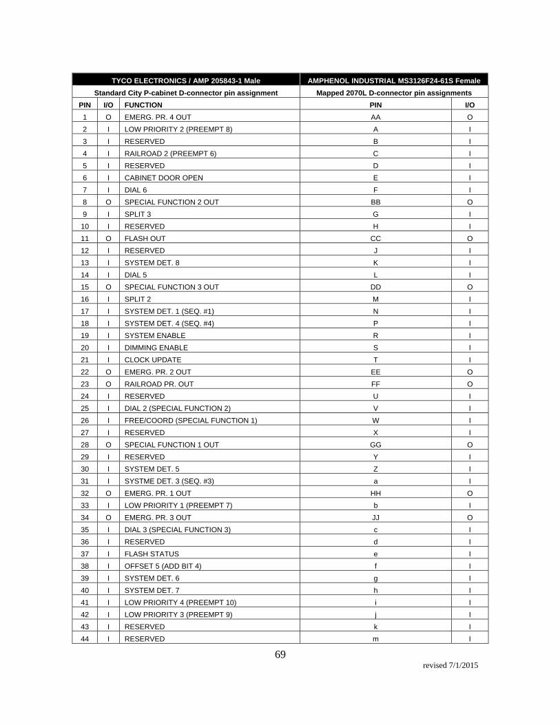
69 revised 7/1/2015
TYCO ELECTRONICS / AMP 205843-1 Male AMPHENOL INDUSTRIAL MS3126F24-61S Female
Standard City P-cabinet D-connector pin assignment Mapped 2070L D-connector pin assignments
PIN I/O FUNCTION PIN I/O
1 O EMERG. PR. 4 OUT AA O
2 I LOW PRIORITY 2 (PREEMPT 8) A I
3 I RESERVED B I
4 I RAILROAD 2 (PREEMPT 6) C I
5 I RESERVED D I
6 I CABINET DOOR OPEN E I
7 I DIAL 6 F I
8 O SPECIAL FUNCTION 2 OUT BB O
9 I SPLIT 3 G I
10 I RESERVED H I
11 O FLASH OUT CC O
12 I RESERVED J I
13 I SYSTEM DET. 8 K I
14 I DIAL 5 L I
15 O SPECIAL FUNCTION 3 OUT DD O
16 I SPLIT 2 M I
17 I SYSTEM DET. 1 (SEQ. #1) N I
18 I SYSTEM DET. 4 (SEQ. #4) P I
19 I SYSTEM ENABLE R I
20 I DIMMING ENABLE S I
21 I CLOCK UPDATE T I
22 O EMERG. PR. 2 OUT EE O
23 O RAILROAD PR. OUT FF O
24 I RESERVED U I
25 I DIAL 2 (SPECIAL FUNCTION 2) V I
26 I FREE/COORD (SPECIAL FUNCTION 1) W I
27 I RESERVED X I
28 O SPECIAL FUNCTION 1 OUT GG O
29 I RESERVED Y I
30 I SYSTEM DET. 5 Z I
31 I SYSTME DET. 3 (SEQ. #3) a I
32 O EMERG. PR. 1 OUT HH O
33 I LOW PRIORITY 1 (PREEMPT 7) b I
34 O EMERG. PR. 3 OUT JJ O
35 I DIAL 3 (SPECIAL FUNCTION 3) c I
36 I RESERVED d I
37 I FLASH STATUS e I
38 I OFFSET 5 (ADD BIT 4) f I
39 I SYSTEM DET. 6 g I
40 I SYSTEM DET. 7 h I
41 I LOW PRIORITY 4 (PREEMPT 10) i I
42 I LOW PRIORITY 3 (PREEMPT 9) j I
43 I RESERVED k I
44 I RESERVED m I

70 revised 7/1/2015
A. Traffic Signal Controller Software
The Contractor shall install Fourth Dimension (D4) Traffic Signal Controller software on each controller assembly. The most current version of D4 Traffic Signal controller software, at the time of controller delivery, shall be fully configured in the 2070L. The Contractor shall provide a D4 license to the City for each controller assembly. The license shall include technical support and user manual of this software.
The contact for the traffic signal controller software is as follows:
Fourth Dimension Traffic Tod Eidson, President 255 King St. #609 San Francisco, CA 94107 Phone: 415-516-4051 Fax: 415-495-9010 Email: [email protected]
General Controller Software Features 1. 16 phases
a. Three maximum times per phase with dynamic max operation b. Minimum, maximum, soft recall modes c. Early and delayed “Walk” timing
45 I RESERVED n I
46 I RESERVED p I
47 I SYSTEM DET. 2 (SEQ. #2) q I
48 --- LOGIC GND. PP ---
49 I EMERG. 1 (PREEMPT 1) r I
50 I EMERG. 2 (PREEMPT 2) s I
51 --- RESERVED KK ---
52 O RESERVED LL O
53 --- LOGIC GND. PP ---
54 --- LOGIC GND. PP ---
55 I EMERG. 3 (PREEMPT 3) t I
56 I EMERG. 4 (PREEMPT 4) u I 57 I RAILROAD 1 (PREEMPT 5) v I 58 I CONFLICT STATUS w I 59 --- RESERVED MM --- 60 I FLASH COMMAND x I 61 I RESERVED y I 62 O RESERVED z O 63 CHASSIS GND.

71 revised 7/1/2015
d. Conditional service during free and coordination with conditional service minimum green time
e. Manual control operation with selectable call, omit, and protected pedestrian clearance phases
f. Per phase preempt timing 2. 4 rings (Single intersection or two independent intersections) 3. 16 timed overlaps
a. Vehicle and pedestrian movement for each overlap b. Actuated pedestrian movements c. Early and delayed “Walk” timing d. Pedestrian overlap rest-in-walk across multiple phases e. Per overlap preempt timing
4. 8 transit phases
a. Two and three section signal head controls for light rail vehicles b. Advanced warning sign control per transit phase c. Recall or actuated operation d. Normal or priority service
Detector Features 1. 64 vehicle detectors
a. Programmable call and extend phases b. Extend and delay timing c. Stop bar disconnect mode with carryover (extend) timer d. Detector cross-switching e. No presence and max fail detector diagnostics (disabled by TOD)
2. 16 queue detectors
a. Detects traffic backups b. Capable of selecting alternate coordination patterns, selecting alternate
maximum green times, or calling a preempt c. Advanced green to clear vehicle movements prior to transit vehicle arrival
3. 16 pedestrian detectors
a. Programmable calls for pedestrian and vehicle phases b. Pedestrian cascade mode (sequential calling of two pedestrian movements)
4. 8 transit detectors
a. Programmable calls for transit and vehicle phases b. Extend and delay timing c. Travel time delay d. Alternate travel times by TOD e. Adaptive arrival time adjustment

72 revised 7/1/2015
5. 32 remote transit detectors
a. Calls received by transit detectors at other intersections (on peer-to-peer Ethernet network)
b. Travel time delay c. Alternate travel times by TOD d. Adaptive arrival time adjustment
Coordination Features 1. 32 coordination patterns
a. Cycle time and three offsets per pattern b. Flexible per phase split expansion and shrinking during transition c. Fixed or floating force-offs (per phase) d. Automatic permissive calculations
2. Single-band or multi-band permissive modes with permissive limit timer 3. Three pedestrian permissive modes
a. Programmable recalls and omits active during each pattern b. Actuated coordinated phases can gap-out early and distribute unused time
to movements with greater demand c. Selectable reservice phases (a.k.a. “fully actuated coordination”)
4. Multiple interconnect modes
a. Time based scheduler b. Central system command (over twisted pair or Ethernet connection) c. 120 volt interconnect cable
5. Master controller mode
a. Controller can operate as a twisted pair, Ethernet, or 120 volt cable master in the absence of a central management system
Preemption Features 1. 10 prioritized preempts
a. Two track clearance states, dwell state, and exit state per preempt b. Permit or allow any phase and overlap individually for each preempt state c. Presence preempt input with optional fail-safe interlock input d. “Check-in / Check-out” preempt detection option with check-out override
timer 2. 4 soft preempts

73 revised 7/1/2015
a. “Step-by-step” preempt (special preempt sequence) b. 8 states per soft preempt sequence (timed or actuated) c. Each state allows programmable calls, omits, holds, and force-offs for
each phase and overlap Transit Priority Features
a. Programmable transit priority options for each transit phase b. Operates based on estimated arrival times using local intersection
detection and remote (“peer-to-peer”) detection from upstream intersections
c. Separate options for free or coordinated operation d. Extend only (no phase abbreviation) or Early/Extend operation e. Minimum phase green times f. Maximum extend limit g. Optional vehicle/pedestrian phase omits h. Ability to switch to alternate sequence to better serve early arriving transit
vehicle i. Adaptive arrival times to automatically compensate for fluctuating station
dwell times Status / Diagnostic Features 1. Detailed controller status displays through the 2070 LCD display
a. Phase, ring, and overlap status b. Transit phase/priority status c. Coordination status d. Preemption status e. Vehicle and pedestrian detector status f. Cabinet / Field I/O status g. System communication status
2. 6000 controller event log
a. Multiple classes of events can be individually enabled for logging b. Retrieved and reset from central connection (serial or Ethernet)
3. 62.5 day detector VOS log
a. Log VOS for 16 system detectors each 15 minutes
4. 600 MMU event log a. Detailed MMU events, including reason for failure and state of field
outputs
Cabinet Support 1. NEMA TS1, TS2-Type 1 and Type 2, Caltrans 332/336, and ITS cabinet support

74 revised 7/1/2015
2. All controller input and output functions can be mapped to any physical cabinet input and output
3. “Peer-to-Peer” interconnect over Ethernet (select outputs or inputs from the source intersection to activate a function at the local intersection)
4. Cabinet logic channels to accomplish custom controller I/O operation Protocol Support 1. Communications over serial port, twisted pair, or Ethernet (fiber-optics) 2. Caltrans AB3418E with extended messages for extended status and D4 specific
functionality 3. Future NTCIP compliance
D. Controller Software Training The Contractor shall provide a minimum of two (2) days, eight (8) classroom hours per day, for a total of sixteen (16) classroom hours of training for operation of manufacturer-supplied controller software (D4), including the operating system, drivers and descriptors, initialization software, and validation suite. This training shall be provided for to up to twenty (20) City staff. The Contactor shall also provide one (1) enterprise virtual D4 suitcase trainer. Location of training will be at City of Sacramento, Corporate Center South, 5730 24th Street, Building #11, Sacramento, CA 95822-3699. The Contractor shall coordinate with the City Inspector to schedule the dates and time of training. E. Testing The Contractor shall comply with electrical, environmental and testing requirements defined in the TEES. The Contractor shall comply with all testing, quality control and reporting procedures specified in the TEES. F. Manuals All equipment (base controller assemblies and all modules) and software provided under this specification shall be provided with product/operational manuals, which document the operation and maintenance of the equipment in compliance with TEES. The Contractor shall furnish ten (10) printed and one (1) electronic copy of operating manual, technical data sheets, product cut sheets, and any associated documentation with delivery of the first controller shipment per Section 1.1, Scope and Location of Work. Manuals shall be printed on 8.5” x 11” inch paper. Schematics, layouts, parts lists and plan details may be on 11” x 17” inch sheets, but the sheets must be neatly folded to 8.5”

75 revised 7/1/2015
x 11” inch size. The manuals shall be bound in durable covers, and shall not suffer degradation when subjected to normal cabinet temperature testing. G. Warranty The 2070L controller equipment and components/modules shall have a full warranty for manufacturer defects and workmanship, including parts and labor for a minimum of five (5) years from the date of acceptance. Identification of manufacturer defects shall be as determined by the City. The Contractor shall submit three (3) copies of all warranty certificates with the first controller shipment per Section 1.1, Scope and Location of work. The Contractor shall bear all expenses for the return and repair of 2070L controller equipment and components or field repair of installed equipment deemed necessary for adjustments during the warranty period.
3.28 Traffic Signal Cabinet 332
The traffic signal cabinet 332 assembly shall contain all necessary components to operate an 8-phase traffic signal. The 332 assembly shall conform to the requirements of “Transportation Electrical Equipment Specifications” (TEES) and “Traffic Signal Control Equipment Specifications” (TSCES). The cabinet construction shall conform to Section 86-3.04 Controller Cabinets of the California Department of Transportation Standard Specifications. Controller cabinet and controller shall be on California Department of Transportation approved list. A. General Equipment a. The cabinet shall be completely equipped, wired and have the following, but not
limited to: 1. (1) Conflict Monitor 2010ECLip 2. (12) Load switches 200 3. (4) Flash Transfer Relays 4. (1) Power Supply Model 206 5. (2) Flasher Units 204 6. (1) Power Distribution Assembly (PDA) #2 7. (8) Inductive Loop Detector Cards Model 222 8. (3) DC Isolator Model 242
b. Two (2) copies of circuit diagrams and operation manual for each major component of control cabinet equipment shall be provided for each cabinet delivered.
c. One (1) set of galvanized anchor bolts shall be included with each cabinet.

76 revised 7/1/2015
d. All identification shall be by means of black and white labeling, painted or self-adhesive labels.
B. Delivery and Acceptance The cabinets shall be delivered to the City of Sacramento with all items required for the operation of the intersection installed. The cabinets shall be tested for complete operation and inspected for conformance to these Special Provisions at the City Traffic Signal Shop. The Contractor shall have an authorized service engineer from the cabinet manufacturer available at the City’s Corporate Center South within one (1) working day after notification to correct all minor malfunctions or make minor modifications to meet these specifications. If major adjustments, modifications or repairs to the cabinet are required to meet these specifications, the Contractor shall be required to repair or modify the cabinet(s) in question at no additional cost to the City. The contractor shall be responsible for all shipping charges for any cabinet(s) that are returned for major repairs or modifications. The Contractor shall also be required to repair or replace any equipment that fails to function properly during testing and inspection. For the first cabinet shipment, the City shall have fifteen (15) calendar dates from date of cabinet receipt to test and inspect the cabinets. For the balance of the cabinets, the City shall have twenty (20) calendar days from date of cabinet receipt to test and inspect the cabinets. C. Guarantee The Contractor guarantees all cabinets, materials and devices of whatsoever nature incorporated in, or attached to the cabinets, to be free of all defects of workmanship and materials for a period of one (1) year after final acceptance of each shipment of Type 'R' controller cabinets by the City of Sacramento. The Contractor shall repair or replace any or all equipment or material, together with all or any other equipment or material which may be displaced or damaged in so doing, that may prove defective in workmanship or material within said one (1) year guarantee period without expense or charge or any nature whatsoever to the City. In the event that the Contractor should fail to comply with the conditions of the foregoing guarantee within (10) days time, after being notified of the defect in writing, the City shall have the right, but shall not be obligated to repair, or obtain the repair of the defect and the Contractor shall pay to the City on demand all reasonable costs and expense of such repair. In the event that any defect in workmanship or material covered by the foregoing guarantee results in a condition which constitutes an immediate hazard to the health or safety, or any property interest, or any person, the City shall have the right to immediately repair, or cause to be repaired, such defect, and the Contractor shall pay to the City on demand all reasonable costs and expense of such repair. The foregoing statement relating to hazards to health, safety or property shall be deemed to include either temporary or permanent repairs, which may be required as determined in the sole discretion and judgment of the City.

77 revised 7/1/2015
3.29 Traffic Signal Cabinet, TS2 Type 1, Type ‘R’
The traffic signal controller cabinet shall be a TS2 Type 1 R44 cabinet. It shall be 77 inches high x 44.5 inches wide x 26 inches deep. For the bolt pattern, refer to Caltrans 2006 Standard Plan ES-3A. It shall have 16 phases of outputs, 64 channels of loop detection inputs, and conform to the following: A. State of California Specifications
Unless otherwise noted, the enclosure specification shall meet or exceed the State of California, Department of Transportation, Standard Specifications, dated 2010, Section 86-3.04A and Standard Plans, section ES-3.
B. NEMA Specifications Unless otherwise noted, the cabinet shall adhere to the latest NEMA TS 2 Type 1
specifications.
C. City of Sacramento Specifications
The City of Sacramento traffic signal cabinet specification shall supersede any applicable parts of the State of California, Department of Transportation Standard Specifications and Standard Plans.
D. Cabinet Construction
1. General Controller cabinets shall be constructed from type 5052-H32 bare aluminum with a dull finish and a minimum thickness of 0.125 inches and be 3R weather rated.
All cabinets shall come with a ten (10) year warranty on the enclosure and cabinet wiring.
Each cabinet shall be provided with two (2) lifting eyes for placing the cabinet on its foundation in the down position. Each eye opening shall have a minimum diameter of 0.75 in. Each eye shall be able to support a weight load of 1000 pounds. All exterior bolt heads shall be tamperproof type.
Machine screws used for mounting equipment on doors or walls of the cabinet shall have inside nuts.
The door latching handles shall have provision for padlocking in the closed position. Each handle shall be 0.75 in minimum diameter cast aluminum or zinc-, cadmium-plated steel, or stainless steel with a minimum 0.5 in shank. The padlocking attachment shall be placed at 4.0 in from the handle shank center to
78 revised 7/1/2015
clear the lock and key. An additional 4.0 in minimum gripping length shall be provided. Louvers shall be located in the lower one-half of the door. All cabinets shall be supplied with pleated dirt filters (ECO/AIR E-35-S) or equivalent, capable of filtering peat dirt. The filters shall be 12" x 16" x 1". A police panel shall be located in the upper center outside of the door. The panel shall have a Signal On/Off switch and an Auto/Flash switch. A maintenance door panel shall be mounted on the inside of the cabinet door on the back side of the police panel. The panel shall have twelve (12) 3-position detector switches for each of eight (8) vehicle and four (4) pedestrian phases. The switches shall operate as fixed, normal, and momentary, top to bottom. They shall be labeled for each phase. Six (6) pushbuttons shall be provided to test the preempt inputs and labeled RR 1, (blank), EVP 1 (3), EVP 2 (4), EVP 3 (5), EVP 4 (6). There shall be a Controller On/Off switch and an Auto/Flash switch. There shall be a three (3) position Stop Time switch; Flash Stop Time On/Off/Manual Stop Time On. There shall be A GFI duplex outlet provided. The controller cabinet shall have a light and fan panel mounted in the top of the cabinet. Each panel shall be equipped with two (2) electric fans with ball or roller bearings and a capacity of at least 100 cubic feet per minute each. Each fan shall be separately fused and thermostatically controlled to the requirements of Section 86 of the State Specifications. There shall be two (2) LED cabinet illumination panels, Relume Technologies #796-5000 or approved equal. One mounts in the fan housing towards the front of the cabinet and the other under the document drawer. The power supply for the panels shall be mounted in the top of the cabinet and shall be 24VDC, 4 Amp. The light shall be rated 100,000 hours per LM 70. Light engine shall be fully recyclable. There shall be a door switch to turn on power to the light panels when the door is open. When the door is closed, the switch shall remove all power to the light panels. The field terminal blocks for the signal indications on the load bay, the detector terminal blocks on the field input panel, and the power terminal block on the power panel shall be barrier type with marker strips and shall be provided with 10-32 by 5/16-inch minimum nickel or cadmium plated brass binder head screw and square metal threaded inserts. Round knurled inserts will not be accepted. All assemblies that are connected in this cabinet shall be connected via hard wire, no quick disconnect or plug and play is accepted. No other equipment within the controller cabinet shall use a socket that will accept a flasher or a flash transfer relay. If relays are required other than the flash transfer relay, they shall be octal relays.

79 revised 7/1/2015
With MMU device disconnected or controller power off, the intersections shall go into flashing operation and remain in flashing operation until controller power is turned on. (THE CITY WILL NOT ACCEPT THE CABINET IF THE INTERSECTION GOES DARK INSTEAD OF FLASH.) All labels shall be silkscreen or phenolic screw on type. No adhesive or sticker labels will be accepted. Font shall be Times New Roman. Font size is determined by location.
2. Left Cabinet Wall
Bottom Field Input Panel: The bottom eight (8) terminal positions on the last terminal block shall be allocated for pedestrian push button and pedestrian common (return) wires. The rest of the terminal positions shall be allocated to detector cable input wires. There shall be sufficient terminal positions for eight (8) pedestrian inputs, two (2) pedestrian returns and sixty-four (64) loop inputs (32 channels). Top Field Input Panel: Shall be wired for sixty-four (64) loop inputs (32 channels). Detector Programming Panels: All the detector outputs and detector green inputs shall be wired to two (2) detector programming panels, the first 32 channels to one and the second 32 channels to the other. Ø1-Ø8 greens shall be wired to the first panel. Ø1-Ø8 vehicle call switches on the maintenance door panel shall be wired to the first panel. SDLC Hub: All cabinets shall come with an SDLC hub with a minimum of eight (8) connectors. All connectors shall be mounted on a PC board. All SDLC cables shall be Belden 9506 or approved equal. The backshell/cable clamp shall be metal and the cable appropriately strain relieved. Opticom cables shall be terminated on the detector power supply panel.
3. Right Cabinet Wall
Power Panel: The Signal controller, TS2 power supply, any other auxiliary power supplies, detector power, etc. shall be protected by the surge protector. The protection device shall be an Edco ACP340, SHP300-10 or approved equivalent device and come with a seven (7) year warranty. The mercury contactor shall be replaced with a normally open, solid state relay and shall be CST Crydom CWA4850, MDI HPR48A50, Omega SSRL 240AC50, or approved equal. There shall be three (3) circuit breakers, a twenty (20) Amp, for the signal circuit, a fifteen (15) Amp for the auxiliary circuit, and a fifteen (15) Amp for the outlet strip. An fifteen (15) position earth ground bus bar and a fifteen (15) position neutral bus bar will be provided. It may be a screw type copper bar as specified in the CalTrans spec or a compression type with holes that will accept 14-8 AWG wire. The service
80 revised 7/1/2015
AC- and bond wire will terminate on the bus bars. A place will be provided for the service AC+ on a terminal strip with a field lug and it shall be an ILSCO #SLUH-35 or approved equal. A 3 position block of type Marathon CAT: 1423570, 1423307, or equal will NOT be accepted. Outlet strip: All cabinets shall have a Tripp-Lite outlet strip model ISOBAR6ULTRA or approved equal and shall be connected to CB-3. Outlet strip shall be mounted on aluminum stock. DIN Rails: There shall be 2 DIN rails mounted on aluminum stock for DIN rail devices.
4. Center of Cabinet
Each controller cabinet shall be provided with three (3) shelves to house the controller, rack mounted detectors and any other equipment supplied, mentioned in the specifications and/or shown on the plans. The top shelf shall contain the all detector amplifiers, and any preemption equipment. The middle shelf shall contain controller and power supply. The bottom shelf shall contain the MMU. The shelves shall be perforated to allow air flow. See attached Cabinet Layout drawing for mounting heights of shelves. An On Battery LED shall be mounted on the underside of the top shelf and shall be readily visible when the door is opened. The LED is part of the BBS relay circuitry located in the loadbay. MMU, power supply, BIU, and controller cables, when not connected to controller or monitor, shall not be long enough for connectors to touch AC field wiring terminals (potential shorting problems). A pull-out laptop computer shelf shall be incorporated below and attached to the bottom shelf. This pull-out shelf shall be 22” wide x 12.5 deep and provide an opening under the bottom shelf lip of 2.5” to be used as a document drawer. Load Bay: The load bay shall be designed to fold down from the top to gain access to the back side. No part of the load bay shall stick out past the load switches. The load resistors for load switches 9 – 12 yellows shall be mounted on the back of the load bay. Load bay shall be silk screened on front, showing all positions, e.g. Ø1, Ø2. Load bay shall accommodate two (2) Bus Interface Units (BIU). With respect to TS2 color output channel assignments, default channel, and therefore load switch and MMU wiring, assignments on the load bay shall be as follows:

81 revised 7/1/2015
a. Channels 1 - 8 shall be assigned to Vehicle Phases 1 - 8 respectively. b. Channels 9 - 12 shall be assigned to Pedestrian Phases 2, 4, 6, and 8
respectively. c. Channels 13-16 shall be assigned to Overlap Phases A, B, C, and D
respectively. Field lugs shall be supplied on all colors for each vehicle and pedestrian phase and each pedestrian pushbutton and pushbutton return. The field lugs shall be ILSCO #SLUH-35 or approved equal. A battery backup relay shall be mounted on the load bay. All power connectors for controller, MMU, and power supply shall be “MIL-SPEC” with no exceptions. All cables for the power supply and MMU shall feed up from the front of the shelf. There shall be two (2) controller power cables.
a. One shall be a NEMA TS1 “A” and feed from the front of the middle shelf. b. The other shall be a NEMA TS2-1 power connector for the traffic signal
controller interface board and feed up from the back of the middle shelf with enough slack so that the controller can be turned sideways to access the cable connectors.
The controller SDLC cable should be long enough to feed up from the front or from the back, depending on the type of controller. The BIU connectors in the load bay and detector racks shall be mounted on PC boards. The cabinet shall be capable of sixty four (64) channels of detection. Two thirty two (32) channel racks may be hard wired or PC board. The detection racks shall accommodate two BIU’s, eight (8) - four channel half width (1.0”) detectors and either two (2) - two channels or one (1) - four channel Opticom discriminators in the first rack. The racks shall be no more than 18 ¾” wide and 5 ¾” high.
E. Auxiliary Devices
All auxiliary devices shall conform to the Requirements of the NEMA TS2 Type 1 Standards. The cabinet shall be equipped with all necessary auxiliary devices to operate a traffic signal with eight (8) vehicle phases, four (4) pedestrian phases and four (4) overlaps. The main auxiliary devices are listed below.
82 revised 7/1/2015
1. Load Switches a. The Load Switch shall be designed for use in traffic signal controller
cabinets in accordance with NEMA TS2 Standards, Section 6.2. b. Load switches shall have a heavy duty aluminum heat sink chassis to
allow triac device to operate with the full load current. 10Amp RMS Maximum Load Current over NEMA temperature range. Operating voltage range of 60 to 135VAC.
c. Unit shall contain three electrical independent circuits. The front of the load switch shall be provided with three indicators to sow the input signal from the controller to the load switch. Maximum load current output in de-energized condition is less than 10 mA peak.
d. Sixteen (16) Load Switches shall be supplied (8 vehicle, 4 peds, 4 overlaps). EDI Model 510 Load Switch or equal for use in NEMA TS2 Type 1 cabinet.
2. Solid State Flashers a. Solid State Flashers shall be in accordance with NEMA TS2 Standards,
Section 6.3. b. Flasher shall have a heavy duty aluminum heat sink chassis to allow triac
device to operate with the full load current. c. 15Amp RMS Maximum Operating Load Current over full NEMA
temperature range. d. Operating voltage range of 60 to 135VAC. e. A minimum of 56 flashes/minute. f. EDI Model 810, Reno Model Fl-200 or equal.
3. Malfunction Management Units (MMU)
a. MMU shall be designed for use in traffic controller cabinets in accordance with NEMA TS2 Standards, Section 4.
b. The MMU shall be a Type 16. c. One (1) conflict monitor shall be supplied. EDI Model MMU-16LE,
Econolite MMU-16, or Reno MMU-1600G.
4. Bus Interface Units (BIU) a. The BIU shall be designed for use in traffic signal controller cabinets in
accordance with NEMA TS2 Standards, Section 8. b. All BIUs shall provide three separate front panel indicators for Power,
Transmit, and Valid Data. c. Six (6) BIU shall be supplied. Two BIU shall be placed in the Load Bay.
Four BIU shall be placed in the Detector Racks. EDI Model 700 or Econolite BIU-64.

83 revised 7/1/2015
5. Cabinet Power Supply
a. The cabinet power supply shall meet all TS2 Section 5 requirements. b. The power supply shall regulated DC power, unregulated AC power, and a
line frequency reference for the Detector Rack, BIU, load switches and auxiliary equipment.
c. Power Supply shall have LED indicators showing output status and fuse integrity for three supply outputs.
d. One (1) Power Supply shall be supplied. Econolite PS200 TS2, EDI Model PS200 TS2, or Reno TS-2 Power Supply.
6. Flasher Transfer Relays a. All Flasher Transfer Relays shall be solid state and conform to the
requirements of NEMA TS2 Section 6. b. A full complement of relays shall be supplied with cabinet to allow for
maximum phase utilization.
7. Inductive Loop Detectors a. Four Channel Rack Mount Detector for TS2 Type 1 traffic signal cabinet. b. Meets NEMA TS 2 specifications. c. Single width (1.12” or 1.14” wide). d. Eight (8) inductive loop detectors shall be supplied. RENO A&E Y/2-200
four channel rack mount detector or approved equal.
F. Equipment Drawing
Equipment drawings shall comply with Section 86-1.04 of the State Specifications and these specifications, with the following changes: The cabinet print shall be laid out on two (2) “D” size sheets. Sheet one (1) shall have the remaining panels, load bay, cables, fans and lights, SDLC Hub Panel, power supply, maintenance malfunction unit (MMU), controller, connector wiring Power Panel, Outlet Strip, and door Maintenance Panel with police panel. The detector field inputs panels, detector racks, and detector programming panels shall be on sheet two (2). The operation manual for each component shall be provided.

84 revised 7/1/2015
Three (3) prints o f the cabinet-wiring diagram shall be supplied with each controller cabinet in addition to an electronic copy. One copy of the cabinet print shall be enclosed in the document drawer under the controller shelf. Entire cabinet schematic wiring diagram shall also be submitted in the form of an AutoCAD Drawing (.pdf will not be accepted), either on a disk or by email to [email protected] John Matoba, City of Sacramento, 916-808-7891.
G. Cabinet Delivery and Acceptance
The cabinet shall be delivered to the City of Sacramento South Area Corporation Yard. The cabinet will be tested for complete operation and inspected for conformance to these Special Provisions at the City Traffic Signal Shop. The Contractor shall have an authorized service engineer from the cabinet manufacturer available at the City’s Corporate Center South within one (1) working day after notification to correct all minor malfunctions or make minor modifications to meet these specifications. If major adjustments, modifications or repairs to the cabinet are required to meet these specifications, the Contractor shall be required to repair or modify the cabinet(s) in question at no additional cost to the City. The contractor shall be responsible for all shipping charges for any cabinet(s) that are returned for major repairs or modifications. The Contractor shall also be required to repair or replace any equipment that fails to function properly during testing and inspection. The City shall have 30 calendar days from the date of receipt to test and inspect the cabinet. H. Guarantee The Contractor guarantees the cabinet, materials and devices of whatsoever nature incorporated in, or attached to the cabinet, to be free of all defects of workmanship and materials for a period of one (1) year after final acceptance by the City of Sacramento. The Contractor shall repair or replace any or all equipment or material, together with all or any other equipment or material which may be displaced or damaged in so doing, that may prove defective in workmanship or material within said one (1) year guarantee period without expense or charge or any nature whatsoever to the City. In the event that the Contractor should fail to comply with the conditions of the foregoing guarantee within (10) days time, after being notified of the defect in writing, the City shall have the right, but shall not be obligated to repair, or obtain the repair of the defect and the Contractor shall pay to the City on demand all reasonable costs and expense of such repair. In the event that any defect in workmanship or material covered by the foregoing guarantee results in a condition which constitutes an immediate hazard to the health or safety, or any property interest, or any person, the City shall have the right to immediately repair, or cause to be repaired, such defect, and the Contractor shall pay to the City on demand all reasonable costs and expense of such repair. The foregoing statement relating to hazards to health, safety or property shall be deemed to include either temporary or permanent repairs, which may be required as determined in the sole discretion and judgment of the City.

85 revised 7/1/2015
TS 2 – Type 1, Type ‘R’ Cabinet Layout

86 revised 7/1/2015
TS 2 – Type 1, Type ‘R’
Field Input Panel, Thermostat and Fan Panel, MMU Programming Card, Conflict Monitor

87 revised 7/1/2015
TS 2 – Type 1, Type ‘R’ BIU (Terminal Facility)

88 revised 7/1/2015
TS 2 – Type 1, Type ‘R’ Standard Loadbay – 8 Phases, 16 Position Assembly
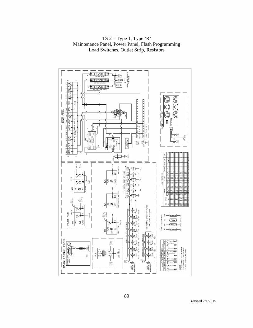
89 revised 7/1/2015
TS 2 – Type 1, Type ‘R’
Maintenance Panel, Power Panel, Flash Programming Load Switches, Outlet Strip, Resistors
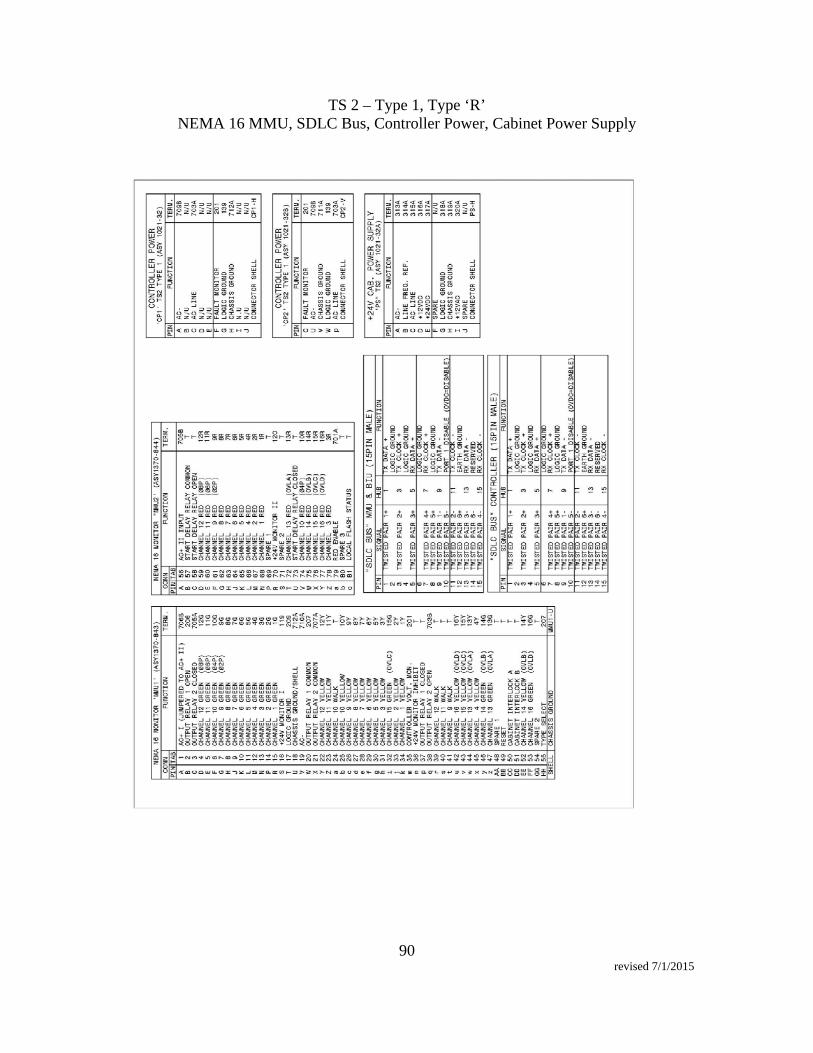
90 revised 7/1/2015
TS 2 – Type 1, Type ‘R’ NEMA 16 MMU, SDLC Bus, Controller Power, Cabinet Power Supply

91 revised 7/1/2015
3.30 Video Detection System – Econolite Vision General This specification sets forth the minimum requirements for a video detection system that detects vehicles, bicycles, and motorcycles on a roadway by processing video images and that provides vehicle presence, traffic flow data, event alarms, and full-motion video for real-time traffic control and management systems. The video detection system shall be comprised of two major hardware components: a video sensor and a communications interface panel. An optional wired input/output card shall be available for certain cabinet types. Camera / Processor The video detection system shall include a video sensor that integrates a high-definition (HD) camera with an embedded processor for analyzing the video and performing detection. The camera shall be a color CMOS imaging array. The camera shall have HD resolution of at least 720p (1280x720 pixels). The camera shall include a minimum 10X optical zoom. It shall be possible to zoom the lens as required to satisfy across-the-intersection detection objectives, including stop line and advance detection. It shall be possible to zoom the lens remotely from the TMC for temporary traffic surveillance operations or to inspect the cleanliness of the faceplate. The camera shall have direct, real-time iris and shutter speed control by the integrated processor. The processor shall support H.264 video compression for streaming output. An integral aiming sight shall assist in aiming the camera for the detection objectives. An adjustable aluminum visor shall shield the faceplate from the sun and extraneous light sources. Power and communications for the video sensor shall be carried over a single three-conductor cable. The video sensor shall operate normally over an input voltage range of 89 to 265 VAC at 50 or 60 Hz. All communications to the video sensor shall be broadband-over-power via the same three-conductor cable that powers the unit. Coaxial cable shall not be required. Communication Interface Panel The video detection system shall include an interface panel in the traffic cabinet that manages communications between the video sensors, the traffic management center, a maintenance technician, and the traffic cabinet itself. The broadband-over-power communications shall provide a throughput of 70 to 90 Mbps. Each video sensor connection shall include a power switch. Each video sensor connection shall contain a resettable fuse. Each video sensor connection shall provide high-energy transient protection. The broadband-over-power connection shall support at least 1,000 feet of cabling to the video sensor. The communications interface panel shall provide connection points for four video sensors. An Ethernet port shall be provided to connect to a remote Traffic Management Center (TMC). The TMC connection shall support 10/100/1000 Mbps Ethernet communication. The communications interface panel shall proxy all network requests that arrive on the TMC connection to avoid unwanted network traffic from reaching the broadband-over-

92 revised 7/1/2015
power network between the communications interface panel and the video sensors. All communications to the video detection system through the TMC connection shall be to a single IP address. A wired Ethernet port shall be provided to connect the technician at the cabinet to the video detection system for setup and maintenance purposes. The maintenance port shall support 10/100/1000 Mbps Ethernet communication. All communications to the video detection system through the maintenance port shall be to a single IP address. The maintenance port shall support DHCP to automatically assign an IP address to the user’s computer, if desired. An 802.11g Wi-Fi access point shall allow wireless connection to the video detection system at the cabinet for setup and maintenance purposes. All communications to the video detection system through the Wi-Fi access point shall be to a single IP Address. The Wi-Fi access point shall support DHCP to automatically assign an IP Address to the user’s computer. The Wi-Fi access point shall include a dipole, omnidirectional antenna. A momentary pushbutton shall allow the user to turn the Wi-Fi access point on or off. The Wi-Fi access point shall turn itself off automatically after a period of inactivity from connected devices. An LED shall indicate when the Wi-Fi access point is enabled. The Wi-Fi access point shall operate simultaneously with the wired maintenance port and with the TMC connection. The communications interface panel shall provide one connection to communicate to the traffic controller through the cabinet. The traffic controller connection shall support a TS2 Type 1 compatible SDLC interface. The traffic controller connector shall be a 15-pin female metal shell D sub-miniature type connector to support a standard NEMA TS2 or TEES SDLC cable. The traffic controller connection shall support a protocol interface to SDLC-capable traffic controllers (NEMA or TEES). The traffic controller connection shall support the NEMA TS2 SDLC protocol to include up to 64 detector outputs and 32 inputs. The traffic controller connection shall be able to connect to a wired input/output card, which supports wired I/O in cabinets without a SDLC-capable controller. The wired I/O data communications link shall support at least 24 outputs and 16 inputs. It shall be possible to connect and use both SDLC communications and communication to the wired input/output card simultaneously. The communications interface panel shall include two USB 2.0 ports. If a communications interface panel fails to start and run due to a software or operating system failure, it shall be possible to reinstall all system and application software from a USB memory stick without necessitating removal of the communications interface panel from the cabinet. The communications interface panel shall accept input voltage in the range of 89-265 VAC, 50/60 Hz power from the transient-protected side of the cabinet. The communications interface panel shall be protected by two slow blow fuses. Spares shall be attached to the panel.

93 revised 7/1/2015
Wired Input/Output Card The video detection system shall support an optional wired input/output card that communicates with the communications interface panel for real-time detection states and other I/O to the traffic controller. The card may reside in a standard detector rack or shelf-mount enclosure with power module. The optional wired input/output card shall comply with the form factor and electrical characteristics to plug directly into a NEMA type C or D detector rack or Caltrans TEES Input File. The card shall occupy two slots of the detector rack. The card shall provide four detector outputs on its rear-edge connector. A front connector shall provide communication to the communications interface panel. A front connector shall allow 16 inputs and 24 contact-closure detector outputs for wiring into the cabinet. A front panel LED for each of the 16 inputs and 24 outputs shall indicate the state of the input or output. The wired input/output card shall support optional expansion cards in other slots. Each expansion card shall support 4 outputs to the back edge of the card. The wired input/output card shall support optional harnesses for connection to Input Files or C1, C4, C11, and C12 ports to support Type 170 or Type 2070 controllers Management Software The video detection system shall include management software for configuration, monitoring and data collection purposes. Management software shall be a Windows-based application. The software shall be compatible with Windows 7 and Windows 10 operating systems. The software shall communicate with the video detection system via Ethernet. The management software shall automatically determine all video sensors and communications interface panels available on the local network and populate a list of all devices. The management software shall provide the user a means to name individual video sensors and communications interface panels. The management software shall provide a means for the user to zoom the camera optics while viewing a live video stream. The management software shall provide a means for the user to calibrate distances in the field of view. The management software shall provide the user a means to create 4-sided detection zones in the field of view using either a still snapshot or live video. The management software will overlay an outline of each detection zone over the background image. It shall be possible for the user to place detection zones anywhere in the field of view for stop line detection and/or advance detection. It shall be possible for the user to set the desired color of both the on and off states of the detection zone overlay. It shall be possible for the user to alter the size and shape of any previously created zone. It shall be possible for the user to overlap zones, either partially or fully. It shall be possible for the user to name each zone uniquely. It shall be possible for the user to assign each zone to detect vehicles, to detect bicycles, or to detect both, and to specify different outputs for each type. It shall be possible for the user to assign the same output to multiple zones such that the output will be on if any of the zones are detecting a vehicle or bicycle. It shall be possible for the user to assign a single zone to more than one output such that if a vehicle or bicycle is detected, all the assigned outputs shall be turned on. The management software shall be capable of creating at least 99 detection zones per video sensor.

94 revised 7/1/2015
It shall be possible for the management software to retrieve all configuration parameters from video sensors or communications interface panels. It shall be possible for the user to save all the settings for a video sensor or a communications interface panel to a laptop file. The management software shall provide a means to read or import all the settings from a previously saved configuration file for a video sensor or a communications interface panel. The management software shall be able to download a new version of the application software into a communications interface panel and its attached video sensors. The management software shall provide a screen to monitor operation of a video sensor. The monitoring screen shall include a live video stream from the video sensor with at least HD 1280x720 pixel resolution. The monitoring screen shall show indications of detection in real time by changing the color of the detection zone. It shall be possible for the user to configure different indications for vehicle detections vs. bicycle detections when both are configured for the same zone. The monitoring screen shall include the following optional, configurable objects. It shall be possible for the user to size and position them anywhere on the screen and to change the color and size of text. An indication of when an output is on or off, along with a user-configurable name for that indicator. The current time in the video sensor. A user-configurable title or name. The version number of the video sensor software. It shall be possible for the user to turn the overlay graphics on or off with a single setting. The management software shall provide a screen to monitor operation of the intersection with a quad-view video stream from the communications interface panel. The quad-view video stream shall have a resolution of at least HD 1280x720 pixels, where each of the sensor videos comprising the quad-view shall be at least 640x360 pixels. It shall be possible for the user to configure the order that the sensor videos appear in the quad-view. The real-time quad-view video stream shall be capable of displaying the overlay graphics for all four sensors simultaneously. While monitoring the video of a single video sensor or of the quad-view, it shall be possible for the user to request a “snapshot” or single-frame image to save to a named file on a laptop. While monitoring the video of a single video sensor or of the quad-view, it shall be possible for the user to record a period of the video to save to a named file on a laptop. System Functionality The video detection system shall detect the presence of vehicles in defined zones and turn on the assigned output when the vehicle is present in the zone. For detection zones placed at the stop line, the probability of not detecting the presence of a vehicle shall be 1% or less under all operating conditions when the video sensor is installed and configured properly. For detection zones placed at the stop line, the probability of falsely detecting a vehicle that is not present shall be 3% or less under all operating conditions when the video sensor is installed and configured properly. It shall be possible to place advance detector zones such that the farthest point of the zone is up to 600 feet from the video sensor. Advance detector zone placement shall include 2-3 car lengths of field-of-view beyond the farthest point of the zone.

95 revised 7/1/2015
To ensure statistical significance for the above detection performance specifications, the data shall be collected over 24-hour time intervals (so as to avoid a single lighting condition) and will contain a minimum of one hundred (100) vehicles per lane. The calculations of detection performance will not include turning movements where vehicles do not pass through the detectors, vehicle lane-change anomalies, or where they stop short or stop beyond the combined detection zones. The video detection system shall provide a failsafe mode for each video sensor. If the failsafe mode is enabled, all programmed presence detection outputs for the video sensor shall be turned on, thus placing constant calls to the controller. When failsafe mode is disabled, all outputs revert to normal on/off operations. The video sensor shall continuously monitor the overall contrast in the video. If the overall contrast falls below a preset level (such as caused by dirty faceplate, severe glare, extreme fog, or temporary ice/snow on the faceplate), the sensor shall enable the failsafe mode. When sufficient contrast is restored in the video, the sensor will disable the failsafe mode. The communications interface panel shall continuously monitor the connectivity status of the attached video sensors. If any video sensor goes offline due to either electrical failure or internal software failure, the communications interface panel shall enable the failsafe mode for that video sensor. If the video sensor comes back online, failsafe mode shall be disabled. The video detection system shall automatically collect and store traffic flow data in non-volatile memory for later retrieval and analysis. No additional hardware or software shall be necessary. The data shall include: Vehicle counts and Vehicle average speeds. The management software shall be able to retrieve collected data for a specified period of time or for all currently stored data and save into a standard CSV file. The communications interface panel and each video sensor shall maintain a time-stamped operations log of routine and special events in non-volatile memory for later retrieval and analysis. The video detection system and management software shall provide three methods to synchronize the time of day clocks in the communication interface panel and the video sensors, as follows: Manual time synchronization operation by the user, which sets the time to the current time on the laptop where the management software is running. A configuration setting to allow the communications interface panel to automatically obtain time from the NEMA TS2 protocol on the SDLC channel and broadcast it to the video sensors. A configuration setting to allow the communications interface panel to automatically obtain time from up to five Network Time Protocol (NTP) sources and broadcast it to the video sensors. In addition to the ability to view video streams in the management software, it shall be possible to view video from individual sensors or to view the quad-view from the communications interface panel using a third-party video player application on a tablet, smartphone or laptop computer.

96 revised 7/1/2015
Installation and Setup The video detection system hardware shall be designed for flexible, fast and easy installation and setup. It shall be possible to mount the video sensor on an intersection pole, mast arm, or luminaire arm. No special tools or extra equipment, other than a laptop for configuration, will be required. Once all hardware is installed, connected and functional, it shall be possible to configure the video detection system for a typical 4-approach, 8-phase intersection in 15 minutes or less. Warranty, Service and Support The video detection system shall be provided with the following warranty, service and support options. The manufacturer shall warrant the video detection system for a minimum of three (3) years. An option for up to six (6) years of warranty shall be available. Ongoing software support by the manufacturer will include software updates of the video sensor, communications interface panel, and management software. These updates will be provided free of charge during the warranty period. The manufacturer will maintain a program for technical support and software updates following expiration of the warranty period. This program will be available to the contracting agency in the form of a separate agreement for continuing support. A quick-start guide, installation guide, application notes, and other materials shall be available from the manufacturer to assist in product installation and setup for various applications. In addition, training online or in person shall be available. Training shall be available to personnel of the contracting agency in application design, operation, setup, and maintenance of the video detection system. Manufacturer shall provide a tech support website and an 800 number for technical support. Video Detection System Hardware Equipment shall be an Econolite Autoscope Vision, or City Traffic Engineer approved equivalent prior to submitting bid.
Qty Hardware
Per
Leg
4 Autoscope Vision (AVISION) white 4 Mounting Brackets (AMBKTM11S) – 24” FT Econolite 3-wire only cable, 18 AWG, Polyethylene jacket
Model 1175-010 for 500 feet. Model 1175-011 for 1000 feet.
Per
In
ters
ecti
on 1 Autoscope Vision Comm Manager (AVCM) 1 SDLC cable
Model 33550G3 for TS2 Cabinet with SDLC Hub 15 pin to 15 pin. Model 33550G5 for TS1 Cabinet with non-2070 controller. Model 33550G8 for TS1 Cabinet with 2070 Model 33274G2 for TS2 Cabinet without an SDLC Hub

97 revised 7/1/2015
1 Ethernet Cable RJ-45 connectors. (200-1020-501) Three (3) years System warranty from of date of acceptance
For cabinets without SDLC hub or connections, a Vision I/O 24 Module shall be installed. Mounting and Connections For Type R cabinet, the Autoscope Vision Comm Manager (AVCM) shall be mounted on a DIN rail attached to aluminum stock for support on the right side of the cabinet. The DIN rail and aluminum stock shall be mounted to the cabinet channel rails. The Contractor is responsible for making all connections per manufacturer recommendations. Camera shall be placed to minimize occlusions of left turn lanes. Occlusions can be minimized by installing the camera on the signal mast arm, in line with the lane striping between the left turn lane and the through lanes. Cameras installed on signal mast arm shall use an extended camera mount. At intersections where the left and through movements go together as standard operation and lefts are not intended to turn separately, the camera can be mounted on a luminaire arm with standard camera mounting bracket. Camera shall be aimed so that the area of detection is in the top half of the video image. The farthest edge of the detector shall be at the top of the image, and at least four (4) cars shall be visible behind the stopbar, in the top half of the video image. No horizon shall be allowed in the video image. All penetration through signal poles or mastarms shall use Hayco Liquid \Tight Cordgrips or approved equal. Penetration shall be at the bottom of the mast arm. Software and Programming An Econolite Representative shall be onsite for the installation and configuration of the Video Detection System at no additional cost to the City. The system shall be programmed to provide stopbar detection. All channels shall be configured per the City’s detector programming sheet and the Contractor and Econolite Representative shall work with City of Sacramento Traffic Signal Maintenance Shop to insure the detection calls are being inputted into the controller. General Aiming and Programming Notes for Video Detection 1. No horizon shall be allowed in video. 2. Camera shall be aimed such that the farthest edge of the detector is at the top of the
image. Four to Five cars shall be visible between the stopbar and the top of the video image.
3. The Camera shall be rotated so the stopbar is horizontal in the video image. 4. Detection Zone shall be approximately 65’ long or 2 cars. 5. Maximum detectable width is 6 lanes and bike lane. 6. Detector labels shall include assigned phase number and assigned channel number.

98 revised 7/1/2015
7. The phase status shall be displayed. Technical Support & Warranty 1. All hardware associated with the video detection system shall be warranted for a
minimum of three years. 2. The vendor shall provide all firmware and software upgrades to the City of
Sacramento free of charge during the warranty period of the product. 3. Technical support shall be free of charge during the warranty period of the product. 4. Vendor shall provide 24/7 technical support. 5. Vendor shall provide training in the operation, setup, and maintenance of the video
detection system, at no additional cost to the city. Surge Suppressor Power Strip Surge Suppressors shall meet the following requirements:
120 VAC 60 Hz All metal housing Isolated filter banks 2350 joule/97,000 amps rating 6 outlets 6 foot cord
Surge Suppressors shall be manufactured by Tripp-Lite Power Protection, Model ISOBAR6ULTRA or approved equal. For Type R cabinet, the Surge Suppressor shall be mounted to the cabinet channel rail, and must be wired to the load side of the 15-amp main breaker in the cabinet. For the Type 332 cabinet, the Surge Suppressor shall be mounted on 2” aluminum stock on the back side of the cabinet near the top using the existing 19” rack. The Surge Suppressor must be plugged into the equipment receptacle on the back of the power assembly of the 332 cabinet. Network Switch with Power Supply Network Switch shall be manufactured by Cisco, Model IE-2000-8TC-B or approved equal. The network switch shall have the following:
Power Supply shall be Cisco, PWR-IE50W-AC-IEC. Cisco 100Base – X small Form Factor Pluggable Module - Two (2) GLC-FE-
100LX-RGD – Cisco device hot-swappable I/O device that plugs into Fast Ethernet ports, dual-rate Fast/Gigabit Ethernet ports, or Gigabit Ethernet ports of Cisco Switch linking the port with the fiber cabling network.
Network Switch shall meet the following requirements:

99 revised 7/1/2015
Industrial grade DIN rail mountable Ethernet connectivity Operate under 14 degrees Fahrenheit to 140 degrees Fahrenheit, and under
vibration and shock Eight (8) 10/100 Base-T Ethernet ports (Small Form0Factor Pluggable (SFP)
downlinks) Two (2) gigabit combo ports: SFP Swappable SD flash card and mini-USB connector LAN lite Software 5-year warranty
For Type R cabinet, network switch shall be mounted on a DIN rail attached to aluminum stock for support. The DIN rail and aluminum stock shall be mounted to the cabinet channel rails. The Contractor is responsible for making all connections per manufacturer recommendations. Power Supply for Network Switch shall meet the following requirements:
Compatible with Cisco IE 2000 Series industrial grade switch DIN rail mountable Input: 100-120 VAC or 200-240 VAC, manually selected AC, 50-60 Hz Operate under 14 degrees Fahrenheit to 140 degrees Fahrenheit, and under
vibration and shock 5-year warranty
Power Supply for Network Switch shall be installed in cabinet. For Type R cabinet, power supply for network switch shall be mounted on a DIN rail attached to aluminum stock for support. The DIN rail and aluminum stock shall be mounted to the cabinet channel rails. The Contractor is responsible for making all connections and shall be made per manufacturer’s recommendations to insure that the switch is powered. See Plans for further details.
3.31 Microwave Vehicle Detection
The contractor shall supply MS Sedco TC26-B Microwave Vehicle Motion Detector, or approved equal by the Engineer, as per following specifications: Model Number……………………………... TC26-B Operating Frequency………………………. 10.525 gHZ (X-band) Detection Method………………………….. Microprocesor analyzed Doppler-

100 revised 7/1/2015
Microwave Detection Pattern(maximum)……………… 200’ long x 50’ wide (cars) 350’ long x 75’wide (truck) Detection Mode……………………………. Directional motion Detection Hold-Time………………………. Continuous with motion Response Time…………………………….. 0.25 seconds Relay Hold-Time…………………………... Variable 0 – 5.0 seconds Power Requirements……………………….. 12 to 24 V AC or DC Current Draw………………………………. 75mA max. @ 24V DC Power Consumption………………………... 1.8 Watts max. @ 24V DC Relay Output……………………………….. Form C, rated at 3 Amps @ 24V DC Wiring Requirements………………………. Multi-conductor (0.36” to 0.47” O.D., 16 gauge Maximum conductor size) Mounting Bracket………………………….. Predrilled & slotted (band or lagbolt Mount) Enclosure/Finish…………………………… Gray powder coated aluminum Operating Temperature……………………. -35 F to 165 F (-35 C to 75 C) Shipping Weight…………………………… Approx 5 lbs. Physical Dimensions………………………. 9.25”L x 5.8”W x 7.37”H 23.5 cm L x 14.73 cm W x 18.72 cm H
3.32 Wiring
Wiring shall be in accordance with Section 34-13 of the Standard Specifications, except for the following:
a. After taping, all splices shall be painted with an approved electrical coating that will
resist oil, acids, alkalies, and adverse environmental conditions. b. Pull ropes used to pull conductors in conduit shall be a minimum of three-eighths
inch (3/8") in diameter.

101 revised 7/1/2015
4. SIGNING AND STRIPING
A. Striping
Thermoplastic traffic stripes and markings and arrows shall be placed as shown on the Plans, in accordance with these Special Provisions, as directed by the Engineer, and in conformance with Sections 84-1 and 84-2 of the State Standard Specifications. All pavement markings and traffic stripes shall be in conformance with the State Standard Plans (latest edition).
Unless covered elsewhere, this item shall cover removal of existing striping necessary to construct the improvements. Removal of pavement shall be by grinding or other method approved by the Engineer.
Material
Thermoplastic shall be Alkyd type for extrusion application and shall produce an adherent reflectorized strip capable of resisting deformation by traffic.
The thermoplastic material shall be 100 percent solids. The binder shall consist of synthetic alkyd resins and shall be homogeneously incorporated with all the necessary prime pigments, fillers, and glass beads to produce a traffic coating to meet the requirements as specified herein.
Characteristics of Finished Thermoplastic:
White Yellow Glass Beads, AASHTO M-247, Type I, percent by weight, min. (Cal. Test Method 423)
30 30
Titanium Dioxode (TiO2), percent by weight, min. (AASHTO T250-77)
10
Lead Chromate, Medium Heat Stability, percent by weight, min.
2.5
Specific Gravity, max. (Cal. Test Method 423)
2.15 2.15
Binder, percent by weight, min. (Cal. Test Method 423)
18 18
Ring & Ball Softening Point, F (ASTM E28)
200 – 240 200 – 240

102 revised 7/1/2015
White Yellow Tests on Material after 4 hours heat with stirring at 425 + 2F, which includes 1 hour for meltdown and temperature stabilization:
Bond Strength to Concrete, 0.125-inch thick film drawdown at 425F test at 75F + 2F, psi, min (Cal. Test Method 423)
180 180
Brookfield Thermosel Viscosity, Spindle SC4-27, 20 RPM at 425F, Poise (Cal. Test Method 423)
30 – 45 30 – 45
Impact Resistance, Falling Ball Method, 0.125-inch thick film drawdown at 425F on concrete. Test at 75F + 2F inch-lbs., (ASTM D2794)
10 10
Daylight Luminous Reflectance, min. (ASTM E97)
75 40
Yellowness Index, max., (ASTM E313)
.15
Hardness, Shore A-2 Durometer with 2 kilogram weight at 115F (Cal. Test 423)
60 – 80 60 – 80
Low Temperature Stress Cracking, Resistance at 25F (AASHTO)
No Crack No Crack
Color Match, Federal Std. No. 595a, Color No. 33538
Passes
Application The thermoplastic material shall be applied by extrusion methods in a single uniform layer. Stencils shall be used when applying thermoplastic material for pavement markings. Stencils may be new or used, if in good condition. If stencils are bent or damaged, they shall be replaced at the request of the Engineer. The pavement surface to which thermoplastic material is applied shall be completely coated by the material and the voids of the pavement surface shall be filled. Unless otherwise specified in the Special Provisions, the thermoplastic material for traffic stripes shall be applied at a minimum thickness of 0.075-inch. Thermoplastic Material for pavement markings shall be applied at a minimum thickness of 0.125-inch. Glass beads

103 revised 7/1/2015
shall be applied immediately to the surface of the molten thermoplastic material, at a rate of not less than 8 lbs. per 100 sq. ft. The amount of glass beads applied shall be measured by stabbing the glass beads tank with a calibrated rod. The Contractor shall apply all traffic stripes and markings on new asphalt surface in accordance with the manufacturer’s recommendations and these Special Provisions. All traffic stripes and markings shall be applied within five (5) calendar days of the placement of the pavement surface course. If the Contractor fails to have all striping and markings applied as required by these Special Provisions, the Contractor shall pay liquidated damages of $500 per calendar day until all work is completed. Tolerances and Appearance The completed traffic stripes and markings shall have clean and well-defined edges without deformations, and shall be free of tears or other disfigurements. Improperly placed, defective, or disfigured traffic stripes and markings shall be immediately removed from the pavement surface by methods approved by the Engineer. All such removal work shall be at the Contractor's expense. Completed traffic stripes shall be uniform, shall be straight on tangent alignment, and shall be on a true arc on curved alignment. On tangent alignment, when a 100' string line is stretched taught and placed directly on the outer edge of the completed traffic stripe, the distance between the string and the edge of the traffic stripe shall not exceed three-fourths of one inch (3/4") when measured anywhere along any 100' interval of the tangent alignment. On curved alignment, the outer edge of the traffic stripe shall not deviate more than three-fourths of one inch (3/4") from the true arc. The lengths of the gaps and individual stripes that form broken traffic stripes shall not deviate more than 2" from the lengths required to produce a uniformly repeating, broken-stripe pattern. Traffic stripes shall be measured by the lineal foot of thermoplastic material placed. No payment will be made for gaps in broken traffic stripes. Double center stripes shall be paid as two (2) four-inch (4") stripes. Triple four crosswalks shall be paid as two (2) four feet (4’) stripes. Pavement markings shall be measured by the square foot of thermoplastic material placed. The quantities of "Thermoplastic Traffic Stripes and Pavement Markings" may be adjusted, deleted, or omitted as directed by the Engineer to meet the existing requirements. No adjustment to the unit price bid will be made because of a change in quantity from the Engineer's estimate. Existing signs shall be removed and salvaged as shown on the Plans and as directed by the Engineer. All mounting hardware shall be removed and salvaged. All salvaged materials shall be returned to the City Corporation Yard, 5730 24th Street, Building 11, Sacramento, California. Contractor is responsible to provide machinery and manpower to unload all salvaged items. Contractor shall coordinate with the city inspector.

104 revised 7/1/2015
B. Relocate Existing Signs Existing signs shall be relocated as shown on the Plans, as directed by the Engineer and as shown in Standard Specifications. The Contractor shall notify the Engineer two (2) working days prior to the relocation of the signs. The Contractor shall review the proposed sign location with the Engineer. The Engineer may make adjustments to the proposed sign location in the field. Contractor shall provide new hardware to hang sign on traffic signal and install new 3/4 inch stainless steel banded strap and appropriate hardware both top and bottom of each sign. C. Place Signs on Mastarms New signs on mast arms shall be installed at the locations shown on the Plans or where designated by the Engineer and in conformance with the provisions in Section 56-2, "Roadside Signs," of the State Standard Specifications and these Special Provisions. Contractor shall place a two individual raps of 3/4 inch stainless steel banded strap and appropriate hardware both top and bottom of each sign. See City Standard Specifications sheet T-301. Sign panels shall be not less than 0.080 inches thick aluminum panels. All panels must be 5052 H38 material. Sign facings shall be manufactured at with type IV or better grade reflective sheeting. Signs shall meet the standards set forth in the MUTCD (Federal standards) California Department of Transportation Traffic Manual. A 3-inch by 1 1/2-inch "City of Sacramento" logo box with 1/2-inch white, red or black letters shall be centered and printed on the lower border of each sign blank prior to application of the reflective sheeting. As an alternative, the "City of Sacramento" logo with 1/2" letters may be placed in the border area. Each sign shall have the date of manufacture and a location number stenciled on the back side. Location information shall consist of each sign having an individual number which will be recorded on a clean set of Plans during the sign installation. This procedure will be in accordance with the "Record Drawings" section of these Special Provisions. The Contractor shall use the sign sizes as shown in the MUTCD (Federal Standards) State of California, Department of Transportation Traffic Manual, unless specified otherwise on the drawings. Contractor shall provide new hardware to hang sign on traffic signal. Install new two individual raps of 3/4 inch stainless steel banded strap and appropriate hardware both top and bottom of each sign.

105 revised 7/1/2015
D. Remove Traffic Markings and Striping
Contractor shall remove existing markings and striping within the project limit as shown on the Plans or as required to place new striping and to complete the striping in place. Thermoplastic and painted preformed traffic markings shall be removed to the fullest extent possible from the pavement by grinding. Material left on the pavement as a result of removing traffic markings shall be removed as the work progresses. Accumulations of material, which might interfere with drainage or constitute a hazard to traffic, Shall not be permitted. The cost of removing raised pavement markers shall be included in this item. Until permanent striping is placed, temporary markers will be in place and included in this item. E. Raised Pavement Markers Raised pavement markers shall be furnished and placed where shown on the Plans or as directed by the Engineer and shall conform to the applicable requirements of Section 32 of the Standard Specifications and these Special Provisions. F. Object Marker (OM2-1)
Object marker (OM2-1V) shall be furnished and placed where shown on the Plans or as directed by the Engineer and shall conform to the applicable requirements of the Standard Specifications, sheet T-250, and these Special Provisions.