the seismic behaviour of semi continuous bridges – a state of the art bridge design in the indian...
TRANSCRIPT

International Journal of Innovative Research in Advanced Engineering (IJIRAE) ISSN: 2349-2763 Issue 06, Volume 3 (June 2016) www.ijirae.com
________________________________________________________________________________________________ IJIRAE: Impact Factor Value – SJIF: Innospace, Morocco (2015): 3.361 | PIF: 2.469 | Jour Info: 4.085 |
Index Copernicus 2014 = 6.57 © 2014- 16, IJIRAE- All Rights Reserved Page -25
“The Seismic Behaviour of Semi continuous Bridges – A State of the Art Bridge Design in the Indian Scenario”
Renuka K. M C. Rajamallu M.E, (Structural Engineering) PG Student, JNTUA, Anantapura, Associate professor, JNTUA, Anantapura, Department of Civil Engineering, Department of Civil Engineering,
Bheema Institute of Technology & Science, Adoni.
Abstract— There is an old saying that, ‘a chain is as weak as its weakest link’. Bearings and expansion joints are the weak links. Hence, interest in Semi-continuous bridges is increasing and their performance has gained international attention. Semi-continuous Bridges are Bridges where the deck is continuous and connected with monolithically with the piers with a moment resisting connection. As an effect we obtain a structure acting as one unit. One of the most important aspects of design, which can affect structure life and maintenance costs is the reduction or elimination of roadway expansion joints. Unfortunately, this is too often overlooked or avoided. Joints and bearings are expensive to buy, install, maintain and repair and more costly to replace. Many of our most costly maintenance problems originated with leaky joints. In the present report the behaviour of Semi-continuous bridges are studied. The loadings which are come across on the Semi-continuous bridges are discussed. And the comparison of Semi-continuous bridges of different spans are discussed by observing the results of maximum and minimum bending moment, shear force and longitudinal stress at top and bottom of bridge deck and deformed shapes and base shear , joint displacements, reactions from equivalent static and response spectrum methods are considered in different zones. In this report, it has been discussed about the performance of Semi-continuous Bridge under different types of loading including seismic loads and which is more suitable for seismic zones.
Keywords—Seismic behaviour, Semi continuous bridges, Bearings, Expansion joints and CSI Bridge
I. INTRODUCTION
The first Bridges were made by nature itself as simple as a log fallen across a stream or stones in the river. The first Bridges made by humans were probably spans of cut wooden logs or planks and eventually stones, using a simple support and crossbeam arrangement. In an age of rapid transportation Bridges are very important. They allow for roads and railroads to cross over otherwise impassable obstacles such as rivers or other roads. By the turn of the century there were three main types of Bridges being used in the United States, the arch Bridge, the Bascule Bridge (Draw Bridge) and the cantilever Bridge. These three types of Bridges reflect the needs and materials available of those who built them.
One of the most important aspects of design, which can affect structure life and maintenance costs is the reduction or elimination of roadway expansion joints and associated expansion bearings. Unfortunately, this is too often overlooked or avoided. Joints and the bearings are expensive to buy, install, maintain and repair and more costly to replace. The most frequently encountered corrosion problem involves leaking expansion joints and seals that permit salt-laden run-off water from the roadway surface to attack the girder ends, bearings and supporting reinforced concrete substructures. Elastomeric glands get filled with dirt, rocks and trash, and ultimately fail to function. Many of our most costly maintenance problems originated with leaky joints.
Bridge deck joints are subjected to continual wear and heavy impact from repeated live loads as well as continual stages of movement from expansion and contraction caused by temperature changes, and or creep and shrinkage or long term movement effects such as settlement and soil pressure. Joints are sometimes subjected to impact loadings that can exceed their design capacity. Retaining hardware for joints are damaged and loosened by snow plows and the relentless pounding of heavy traffic. Broken hardware can become a hazard to motorists, and liability to owners. Decks joints are routinely one of the last items installed on a Bridge and are sometimes not given the necessary attention it deserves to ensure the desired performance. While usually not a significant item based on cost, Bridge deck joints can have a significant impact on a Bridge performance. A wide variety of joints have been developed over the years to accommodate a wide range of movements, and promises of long lasting, durable, effective joints have led States to try many of them. Some joint types perform better than others but all joints can cause maintenance problems.
Bearings also are expensive to buy and install and more costly to replace. Over time steel bearings tip over and seize up due to loss of lubrication or build-up of corrosion. Elastomeric bearings can split and rupture due to unanticipated movements or ratchet out of position. Because of the underlying problems of installing, maintaining and repairing deck joints and bearings, many States have been eliminating joints and associated bearings where possible and are finding out that joint less Bridges can perform well without the continual maintenance issues inherent in joints.

International Journal of Innovative Research in Advanced Engineering (IJIRAE) ISSN: 2349-2763 Issue 06, Volume 3 (June 2016) www.ijirae.com
________________________________________________________________________________________________ IJIRAE: Impact Factor Value – SJIF: Innospace, Morocco (2015): 3.361 | PIF: 2.469 | Jour Info: 4.085 |
Index Copernicus 2014 = 6.57 © 2014- 16, IJIRAE- All Rights Reserved Page -26
The use of expansion joints and bearings to accommodate for thermal movements does not avoid maintenance problems; rather, the provision to these items can often facilitate such problems.
The following quote is very appropriate for Bridge engineering:
“A Quality is never an accident. It is always the result of high intention, sincere effort, intelligent direction, and skilful execution”.
It represents the wise choice of many alternatives. This is especially true when the Engineer begins the task of planning, designing and detailing a Bridge structure. The variables are many, each of which has a different, first and life cycle, cost factor. The question to be asked continuously through the entire process is what value is added if minimum cost is not selected?
Another question to be asked is what futures should be incorporated in the structure to reduce the first and life cycle cost and enhances the quality? Most of the variables are controlled by the designer. These decisions influence the cost and quality of the project; for better or for worse
II. OBJECTIVES AND SCOPE OF WORK The objectives of the work are to;
Study the behaviour of semi-continuous bridge and to determine the time period and natural frequencies of semi-continuous Bridge and to find its base reaction of Semi-continuous Bridge in X(longitudinal) and Y(transverse) direction for Response spectrum method and equivalent static method, and to find its Lateral displacement of semi-continuous Bridge in Longitudinal and transverse direction for both response spectrum method and Equivalent static method and to determine the deformed shape of semi-continuous Bridge deck for dead load, moving load and various seismic loads in different zones, and to find the Maximum and minimum shear force, bending moment due to dead load and Different IRC Moving loads, and to determine the maximum and minimum Shear force, Bending moment and longitudinal stress due to response spectrum method.
The scope of the work is as follows;
1. The study contains the brief introduction about the semi-continuous bridges. 2. The study limited to the semi-continuous bridge with simply supported abutment and fixed piers and assuming no
earth pressure on piers. 3. The study contains the effect of dead load, moving load, and seismic load individually on semi-continuous bridge.
III. METHODOLOGY
Finite element method is the most versatile method, which can easily accommodate structures of complicated shapes, and boundary conditions it involves subdivision of the structure into number of elements, each connected to the neighbouring elements through nodal points. In displacement formulation, the displacement field within each element is assumed in terms of nodal displacements. The element properties are expressed in terms of matrices, and the governing equation of the structure response is then established through the application of appropriate variation principle. The final governing equation thus obtained is purely algebraic which is to be solved in order to obtain the response of the structure by proper choice of elements and suitable subdivision of the structure into large number of elements any desired accuracy can be achieved through finite element method.
METHODS OF ENGINEERING ANALYSIS; To improve the understanding of the behaviour of a structure, the analysis may be performed in three different ways:
1. ANALYTICAL METHODS 2. EXPERIMENTAL METHODS 3. NUMERICAL METHODS
Analytical methods provide quick close-form solutions, but they treat only small geometries and capture only the idealized structural theory. By understanding experimental techniques, representatives or full-scale models can be tested. Experimentation is costly relative to the analytical methods both in term of test facilities, the model, instrumentation and actual test time. Numerical methods require very few restrictive assumptions and can treat complex geometries. They are far more cost effective than experimental techniques. The most versatile numerical method available for the engineer is the Finite Element Method (FEM).
APPLICATIONS; Mechanical/Aerospace/Civil/Automobile Engineering, Structure analysis (static/dynamic, linear/nonlinear) Thermal/fluid flows, Electromagnetic, Geomechanics, and Biomechanics.

International Journal of Innovative Research in Advanced Engineering (IJIRAE) ISSN: 2349-2763 Issue 06, Volume 3 (June 2016) www.ijirae.com
________________________________________________________________________________________________ IJIRAE: Impact Factor Value – SJIF: Innospace, Morocco (2015): 3.361 | PIF: 2.469 | Jour Info: 4.085 |
Index Copernicus 2014 = 6.57 © 2014- 16, IJIRAE- All Rights Reserved Page -27
STEPS IN FINITE ELEMENT METHOD
The following are the steps involved in application of finite element method;
1. MODELLING 2. DISCRETIZATION OF STRUCTURE 3. SELECTION OF PROPER FIELD MODEL 4. DERIVATION OF ELEMENT CHARACTERISTICS 5. ASSEMBLAGE OF ELEMENTAL EQUATIONS TO OBTAIN OVERALL EQUILIBRIUM EQUATIONS 6. SOLUTION OF UNKNOWN NODAL DISPLACEMENTS/FIELD VARIABLE 7. COMPUTATION OF RESULTS/ELEMENTAL STRAINS
IV. SEISMIC ANALYSIS AND DESIGN
An earthquake is the result from the sudden release of stored energy in the Earth's crust that creates seismic waves. At the Earth's surface, earthquakes may manifest themselves by a shaking or displacement of structures on the ground. An earthquake is caused by tectonic plates getting stuck and putting a strain on the ground. The strain becomes so great that rocks give way by breaking and sliding along fault planes. Earthquakes may occur naturally or as a result of human activities. Smaller earthquakes can also be caused by volcanic activity, landslides, mine blasts, and nuclear tests. In its most generic sense, the word earthquake is used to describe any seismic event whether a natural phenomenon or an event caused by humans that generates seismic waves. An earthquake's point of initial ground rupture is called its focus or hypocenter. The term epicenter means the point at ground level directly above this.
SEISMIC DESIGN PHILOSOPHY
The philosophy of seismic design can be summarized as follows;
During the minor but frequent ground motions, the structural members of the Bridge that carry vertical and horizontal forces should not be damaged; however non-structural members may sustain repairable damage. During moderate but occasional ground motions, the structural members may sustain repairable damage, while the other non-structural members of the Bridge may be damaged such that they may even have to be replaced after the earthquake and During strong but rare ground motions, the structural members may sustain severe (even irreparable) damage, but the Bridge should not collapse.
Thus the Bridge will be fully operational after minor shaking, within a short time and the repair costs will be small. And, after moderate shaking, the Bridge will be operational once the repair and strengthening of the damaged structural members is completed. But the Bridge may become dysfunctional for further use after a strong earthquake, but will stand so that people can be evacuated and property is recovered. The consequences of damage have to be kept in view in the design philosophy and desired level earthquake forces should be considered in the Bridge design.
In this study the seismic design consider the effect of :
1. EQUIVALENT STATIC METHOD 2. RESPONSE SPECTRUM METHOD
1. EQUIVALENT STATIC METHOD: Along any principal direction, the total design lateral force or design base shear is given in terms of design horizontal seismic coefficient and seismic weight of the structure. Design horizontal seismic coefficient depends on the zone factor of the site, importance of the structure, response reduction factor of the lateral load resisting elements and the fundamental period of the structure.
2. RESPONSE SPECTRUM METHOD: The response spectrum represents an interaction between ground acceleration and the structural system, by an envelope of several different ground motion records. For the purpose of the seismic analysis the design spectrum given in IS 1893 (Part 1): 2002 is used. This spectrum is based on strong motion records of eight Indian earthquakes.
V. MODELING OF SEMI CONTINUOUS BRIDGES
For the design and analysis of semi-continuous Bridges, three different models are carried out in CSI Bridge 2015 software and the conclusions are drawn by comparison. The dimension of Bridge is considered and some data are assumed in the present work of modelling of semi continuous bridge is as follows.
Dimension of Bridge; Total Length of Bridge =83m, 50m, 120m Number of spans = 2 (each of 41.5m, 25m, 120m length)

International Journal of Innovative Research in Advanced Engineering (IJIRAE) ISSN: 2349-2763 Issue 06, Volume 3 (June 2016) www.ijirae.com
________________________________________________________________________________________________ IJIRAE: Impact Factor Value – SJIF: Innospace, Morocco (2015): 3.361 | PIF: 2.469 | Jour Info: 4.085 |
Index Copernicus 2014 = 6.57 © 2014- 16, IJIRAE- All Rights Reserved Page -28
Width of deck = 12m Number of lanes = 3 Shape of pier = rectangular Height of pier = 18m Materials Concrete = M45 Steel = Fe415 Here considering the abutments are simply supported and piers are fixed and assuming no earth pressure on the abutment and piers.
STATIC CHARACTERISTICS OF SEMI CONTINUOUS BRIDGES LOADS ON BRIDGES: The selection of structural system is one of the most important factors in Bridge design, since the structural system governs the behaviour of the structure. Cost effectiveness of construction and maintenance, durability, seismic performance, vibration serviceability are largely influenced by structural system. Thus, the loads act on the bridges are appropriately modelled and calculated in design. The following loads are to be considered in the integral Bridge design and analysis. As per IRC: 6-2014 the loads to be considered are Dead load, Live load and Seismic load As per IRC: 6-2014 the live load combination is depends on the width of carriage way and number of lanes to be designed. Whether the Bridge has simply supported span, is of continuous construction, or is an integral Bridge, the effects of these loading groups are very similar, though the distribution of forces and deformations differ. The design of Bridges with these different forms of articulation differs mainly in the treatment of constraint forces caused, for instance, by such as temperature and creep effects.
VI. RESULTS AND DISCUSSIONS
Seismic response of semi-continuous Bridges by the method of Response-Spectrum presented in IS 1893: 2000, is carried out using CSI BRIDGE MODELLER commercial software package. The following parameters of the semi-continuous Bridge structures are studied, Lateral displacement Time period and frequency Base reactions Deformed shape of semi-continuous bridge deck for different loading Maximum and minimum bending moment and shear force and longitudinal stress at top and bottom of bridge deck. The variation in the above mentioned parameters are studied as a function of the structure in different seismic zones (III, IV, V). Since zone III, IV and V are the critical loading cases, to study the behaviour of the bridge in the worst loading condition these zones III, IV, V are considered in this work.
COMPARISION OF RESULTS FROM ALL THE THREE MODELS TABLE 1 VARIATIONS OF BENDING MOMENT OF THREE DIFFERENT MODELS
MAX BENDING MOMENT FOR 25 MT SPAN FOR 41.5MT SPAN FOR 60 MT SPAN
kN - m kN - m kN - m dead load at Compression 9616.32 24425.97 49869.49
dead load at Tension -13997.29 -41333 -86886.2 crash barrier @ Compression 894.379 2392.089 4997.84
crash barrier @ Tension -1364.496 -4122.71 -8794.96 wearing coat @ Compression 562.8981 1510.0012 3142.8742
Wearing coat @ Tension -854.1428 -2580.89 -5501.85 IRC A loading @ Compression 2618.48 7688.021 12750.31
IRC A loading @ Tension -2245.65 -6269.02 -7722.33 IRC 70 R loading @
Compression 4344.3716 9340.16 12696.71 IRC 70 R loading @ Tension -2642.414 -5287.69 7374.89
ZONE 3 IN X direction 92.4496 115.6067 134.7669 ZONE 4 IN X direction 138.6989 173.41 203.6503 ZONE 5 IN X direction 208.0484 260.115 305.47 ZONE 3 IN Y direction 56.7686 48.7867 50.1092 ZONE 4 IN Y direction 85.0832 73.18 75.1638 ZONE 5 IN Y direction 127.6235 109.7701 112.7586

International Journal of Innovative Research in Advanced Engineering (IJIRAE) ISSN: 2349-2763 Issue 06, Volume 3 (June 2016) www.ijirae.com
________________________________________________________________________________________________ IJIRAE: Impact Factor Value – SJIF: Innospace, Morocco (2015): 3.361 | PIF: 2.469 | Jour Info: 4.085 |
Index Copernicus 2014 = 6.57 © 2014- 16, IJIRAE- All Rights Reserved Page -29
TABLE 2 VARIATIONS OF SHEAR FORCES OF THREE DIFFERENT MODELS
SHEAR FORCES FOR 25 MT SAPN FOR 41.5 MT SPAN FOR 60 MT SPAN kn-m kn-m kn-m
dead load at Compression 3082.67 5084.93 7297.15 dead load at Tension -3078.94 -5086.64 -7297.15
crash barrier @ Compression 290.59 500.3121 732.764 crash barrier @ Tension -290.59 -500.6121 -732.764
wearing coat @ Compression 181.98 314.6651 459.55 Wearing coat @ Tension -181.98 -314.6651 -459.55
IRC A loading @ Compression 588.24 1205.3772 12750.134 IRC A loading @ Tension -575.45 -1206.75 -7722.33
IRC 70 R loading @ Compression 4344.3716 1147.286 12696.73 IRC 70 R loading @ Tension -2642.4 -1154.619 -7374.896
ZONE 3 IN X direction 92.4496 6.3547 135.766 ZONE 4 IN X direction 138.6989 9.5321 203.6503 ZONE 5 IN X direction 208.0484 14.2982 305.4755 ZONE 3 IN Y direction 56.7216 9.3903 50.1092 ZONE 4 IN Y direction 85.0823 14.0854 75.1638 ZONE 5 IN Y direction 127.6235 21.1282 112.7496
GRAPH 1 COMPARISON OF FREQUENCY RESULTS IN GRAPHS
Graph 1.1
Graph 1.2
GRAPH 2. COMPARISON OF BENDING MOMENTS RESULTS IN GRAPHS

International Journal of Innovative Research in Advanced Engineering (IJIRAE) ISSN: 2349-2763 Issue 06, Volume 3 (June 2016) www.ijirae.com
________________________________________________________________________________________________ IJIRAE: Impact Factor Value – SJIF: Innospace, Morocco (2015): 3.361 | PIF: 2.469 | Jour Info: 4.085 |
Index Copernicus 2014 = 6.57 © 2014- 16, IJIRAE- All Rights Reserved Page -30
Graph 2.1
Graph 2.1
Graph 2.2
Graph 2.3

International Journal of Innovative Research in Advanced Engineering (IJIRAE) ISSN: 2349-2763 Issue 06, Volume 3 (June 2016) www.ijirae.com
________________________________________________________________________________________________ IJIRAE: Impact Factor Value – SJIF: Innospace, Morocco (2015): 3.361 | PIF: 2.469 | Jour Info: 4.085 |
Index Copernicus 2014 = 6.57 © 2014- 16, IJIRAE- All Rights Reserved Page -31
Graph 2.4
Graph 2.5
Graph 2.6
International Journal of Innovative Research in Advanced Engineering (IJIRAE) ISSN: 2349-2763 Issue 06, Volume 3 (June 2016) www.ijirae.com
________________________________________________________________________________________________ IJIRAE: Impact Factor Value – SJIF: Innospace, Morocco (2015): 3.361 | PIF: 2.469 | Jour Info: 4.085 |
Index Copernicus 2014 = 6.57 © 2014- 16, IJIRAE- All Rights Reserved Page -32
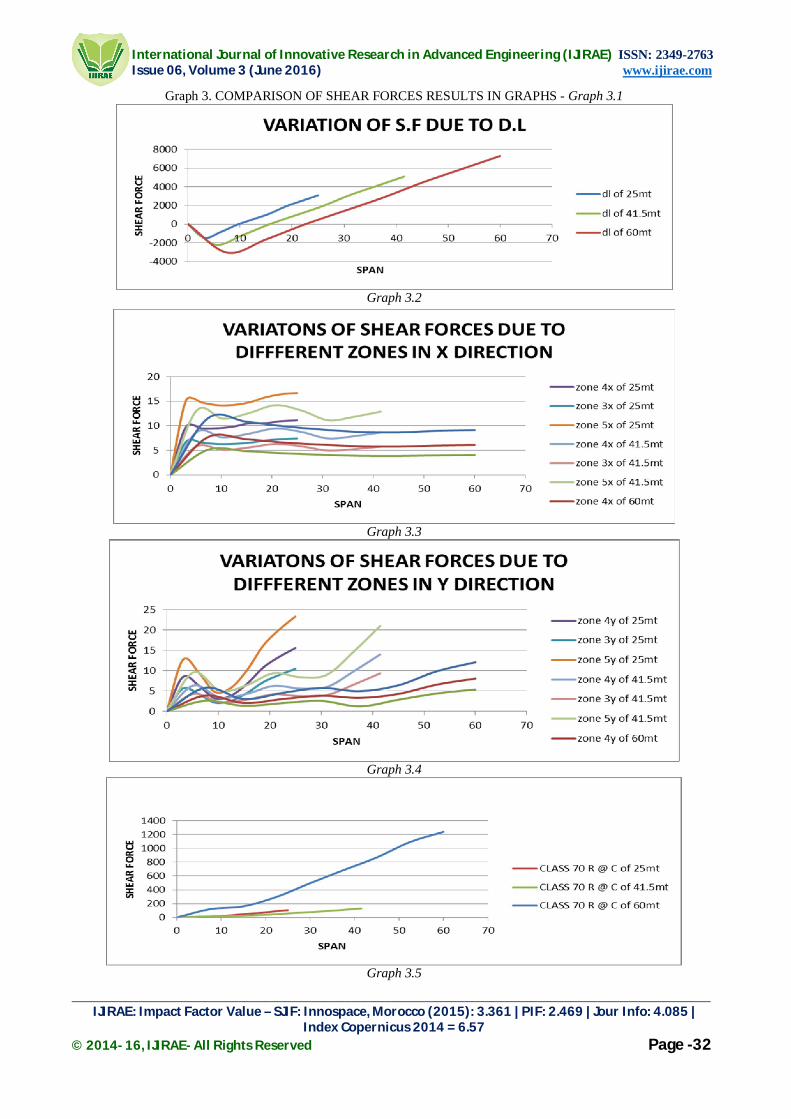
Graph 3. COMPARISON OF SHEAR FORCES RESULTS IN GRAPHS - Graph 3.1
Graph 3.2
Graph 3.3
Graph 3.4
Graph 3.5

International Journal of Innovative Research in Advanced Engineering (IJIRAE) ISSN: 2349-2763 Issue 06, Volume 3 (June 2016) www.ijirae.com
________________________________________________________________________________________________ IJIRAE: Impact Factor Value – SJIF: Innospace, Morocco (2015): 3.361 | PIF: 2.469 | Jour Info: 4.085 |
Index Copernicus 2014 = 6.57 © 2014- 16, IJIRAE- All Rights Reserved Page -33
Graph 3.6
Graph 4. COMPARISON OF REACTION RESULTS IN GRAPHS - Graph 4.1
VII. CONCLUSION
Bending moment of dead load goes on increasing with the increase in the span length in both tension and compression.
Bending moment will be maximum at the support for negative bending moment, positive maximum bending moment will occur at 15.8m and 67.19m distance of span from end supports.
Bending moment of crash barrier and wearing coat increases as the span length goes on increasing. In live load conditions, both in IRC class A loading and IRC class 70R loading, bending moment increases as the
span length increases. In most of the cases IRC 70R loading is found to be critical. In zone 3,4, and 5 bending moment increases in both longitudinal and transverse direction as the span length
increases. Most severe bending moment is developed for zone V loading case.

International Journal of Innovative Research in Advanced Engineering (IJIRAE) ISSN: 2349-2763 Issue 06, Volume 3 (June 2016) www.ijirae.com
________________________________________________________________________________________________ IJIRAE: Impact Factor Value – SJIF: Innospace, Morocco (2015): 3.361 | PIF: 2.469 | Jour Info: 4.085 |
Index Copernicus 2014 = 6.57 © 2014- 16, IJIRAE- All Rights Reserved Page -34
Shear forces increases with increasing in the length of the span. Frequency of vibration decreases as the length of the span increases. Modal participation increases as the length of the span increases. Reactions will be maximum at the interior support girders than the exterior. Reaction increases as the span length increases.
REFERENCES
[1]. Karantzikis and spyrakos - seismic analysis of bridges including soil abutment interaction - 12 wceee – 2000 [2]. Fowler and Stofko - Precast Options for Bridge Superstructure Design– AnnualConference of the Transportation
Association of Canada – 2007 [3]. Iwasaki, T - Earthquake-Resistant Design of Bridges in Japan - Bulletin of Public WorksResearch Institute,
Ministry of Construction, May 1973. [4]. Stergios A. Mitoulis · Ioannis A. Tegos - Restrain of a seismically isolated bridge by external stoppers – Bull
earthquake engineering- 2010 [5]. Reza S.Jalali , MasoumehBahariJokandan , MihailoDTrifunac - Earthquake response of a three-span bridge, with
mid-span supported by isolators, to near-field pulse and permanent-displacement step - Soil Dynamics and Earthquake Engineering – 2013
[6]. S. Maleki- Effect of deck and support stiffness on seismic response of slab girder Bridges – engineering structures - 2002
[7]. S. Maleki –Deck modeling for seismic analysis of skewed slab-girder bridges - engineering structures – 2002 [8]. Chen Y - An Effective and Efficient Approach for Nonlinear Seismic Analysis of Bridges – 1994 [9]. L. Lou, A. Zerva - Effects of spatially variable ground motions on the seismic response of a skewed, multi-span,
RC highway bridge - Soil Dynamics and Earthquake Engineering – 2005 [10]. X.Q. Zhu, S.S - Moving load identification on multi-span continuous bridges with elastic bearings – Mechanical
systems and Signal processing – 2006 [11]. IRC Codes Used IRC 5 (2015), IRC 6 (2014), IRC 112 (2011) [12]. IS-1893 (part-I 2002) [13]. CSI Bridge modeler – 2015 Help