the seaweed remotely operated vehicle senior design …my.fit.edu/~swood/seaweedfinalreport.pdf ·...
TRANSCRIPT
1
The SeaWeed Remotely Operated Vehicle
Senior Design Project
Submitted to:
Dr. Stephen Wood, P.E.
Professor of Ocean Engineering Design (OCE 4541)
FLORIDA INSTITUTE OF TECHNOLOGY
Melbourne, FL
Submitted By:
Nick Abruzzini
Janelle Boisvert
Katie Dobek
Anthony Tedeschi
July 25, 2007
2
TRANSMITTAL______________________________________________
Florida Institute of Technology
Department of Marine and Environmental Systems
OCE 4541
TO:
Dr. Stephen Wood, P.E. Dept. of Marine and Environmental Systems Florida Institute of Technology 150 W. University Blvd. Melbourne, FL 32901
FROM:
The SeaWeed ROV Team
Nick Abruzzini, Janelle Boisvert, Katie Dobek, Anthony Tedeschi
Department of Marine and Environmental Systames
Florida Institute of Technology
150 W. University Blvd.
Melbourne, FL 32901
RE: SeaWeed Remotely Operated Vehicle Senior Design Project
DATE SUBMITTED: July 25, 2007
Dr. Stephen Wood, P.E.:
Please review the attached final report for the SeaWeed ROV Senior Design Project. All
research and calculations completed over the course of this project are included. This
report has been prepared independently and to the best of the team’s ability. Please
contact us at [email protected] if you have any further questions. Thank you.
The SeaWeed ROV Team
Nick Abruzzini _____________________
Janelle Boisvert _____________________
Katie Dobek _____________________
Anthony Tedeschi _____________________
3
Final Report
Senior Design Project
Nicholas Abruzzini
Janelle Boisvert
Katherine Dobek
Anthony Tedeschi
4
Executive Summary:
Remotely operated vehicles have become an essential tool in the oceanographic,
offshore and shipping industries. SeaWeed will be an observational ROV designed for
visual inspection, research and minimal data collection. Taking inspiration from several
small-class observational ROVs as well as two previous Florida Tech Senior Design
Projects (Hornet I and Hornet II) we plan to design and build a base ROV that can
operate as is but has much room for improvement and additions that future students can
work towards. SeaWeed will feature an instrument package that includes depth and
temperature sensors and a compass. It will also have a color camera to capture video that
will be displayed on a monitor mounted in the topside control box. We hope that this
ROV will prove that a low-cost ROVs can be as effectively used in the shipping and
offshore industries as its higher-cost competitors.

5
Acknowledgements:
We would like to thank the following people and companies for their help and support of
our Seaweed ROV, without their time and efforts our project would not have been a
success:
Dr. Wood, Florida Institute of Technology
Larry Buist, Florida Institute of Technology
Dr. Swain, Florida Institute of Technology
Maila Sepri, Florida Institute of Technology
Thomas Dobek, Repair Industries of Michigan
Ben Klose, Repair Industries of Michigan
Joe Knoth, Alliance Tool and Machine, Co.
Bill Jorgensen, Bluewater Fabricators
Mainstreet Pub
Jason Sperry, Easylift Gas Springs
1
Table of Contents:
1. Introduction ............................................................................................................... 6
1.1 Overview ............................................................................................................. 6
1.2 Objectives ........................................................................................................... 7
1.3 Organization ........................................................................................................ 7
2. Background ............................................................................................................... 8
2.1 Florida Tech ROV History.................................................................................. 8
2.2 Competitors ......................................................................................................... 9
3. Technology ............................................................................................................... 11
3.1 History............................................................................................................... 11
4. Materials and Parts................................................................................................. 12
4.1 Parts List ........................................................................................................... 12
4.2 Parts and Materials Description ........................................................................ 13
4.2.1 Frame and Housing .................................................................................. 13
4.2.2 Pressure Sensor ........................................................................................ 18
4.2.3 Monitor ..................................................................................................... 18
4.2.4 Light .......................................................................................................... 18
4.2.5 Propulsion ................................................................................................. 19
4.2.6 Kort Nozzle................................................................................................ 21
4.2.7 DC-DC Converter ..................................................................................... 22
4.2.8 AC-DC Front End ..................................................................................... 23
4.2.9 Video Camera MB-1050C model ............................................................ 23
4.2.10 Video Overlay ........................................................................................... 24
4.2.11 Pelican Box ............................................................................................... 24
4.2.12 Tether ........................................................................................................ 25
4.2.13 Joystick ...................................................................................................... 26
5. Procedures ............................................................................................................... 27
5.1 Preliminary Design ........................................................................................... 27
5.1.1 Design Considerations .............................................................................. 27
5.1.2 Final Design Decisions ............................................................................. 29
5.2 Housing Design and Manufacturing ................................................................. 29
5.2.1 Housing Dimensions ................................................................................. 29
5.2.2 Housing Materials .................................................................................... 29
5.2.3 Housing Design ......................................................................................... 30
5.2.3.1 Outer Housing ....................................................................................... 31
5.2.3.2 Internal Systems Mount ........................................................................ 31
5.2.4 Housing Manufacturing ............................................................................ 32
5.3 Frame Design and Manufacturing .................................................................... 32
5.3.1 Frame Dimensions .................................................................................... 32
5.3.2 Frame Materials ....................................................................................... 32
5.3.3 Frame Design............................................................................................ 32
*Note: CAD Drawings can be found in Appendix C .............................................. 32
5.3.3.1 Outer Frame .............................................................................................. 33
5.3.3.2 Motor Mounts ....................................................................................... 33
2
5.3.3.3 Lighting Mount ..................................................................................... 34
5.3.4 Frame Manufacturing ............................................................................... 35
5.4 Internal Systems ................................................................................................ 35
5.4.1 Introduction............................................................................................... 35
5.4.1.1 Compass .................................................................................................... 36
5.4.1.2 Pressure Sensor ........................................................................................ 36
5.4.1.3 Video and Data Transmission ................................................................... 37
5.5 Steering and Propulsion .................................................................................... 37
5.5.1 Power Supply and Transmission ............................................................... 37
5.5.2 Motor Controller Design .......................................................................... 37
5.5.3 Joystick Integration ................................................................................... 37
5.6 Buoyancy and Stability ..................................................................................... 37
5.6.1 Syntactic Foam.......................................................................................... 38
5.6.2 Buoyancy Calculations ............................................................................. 38
5.7 Control Box Design .......................................................................................... 39
5.7.1 Pelican Box Modifications ........................................................................ 39
5.7.1.1 Gas Spring Hinge .................................................................................. 39
5.7.2 Monitor ..................................................................................................... 40
5.7.2.1 Mounting System .................................................................................. 40
5.7.3 Plastic Mold .............................................................................................. 40
5.7.3.1 Design and Manufacturing .................................................................... 40
5.7.3.2 Spring Mechanism ................................................................................ 41
5.7.3.3 Electronics Mounting ............................................................................ 42
5.7.4 Additions ................................................................................................... 42
5.8 Tether Modifications and Tether Management System Design ....................... 43
5.8.1 Basic Hose Reel ........................................................................................ 43
5.8.2 Slip Ring Modification .............................................................................. 43
5.8.3 Slip Ring Cover Modification ................................................................... 43
5.8.4 Basic Tether Properties ............................................................................ 44
5.8.5 Adding Connectors.................................................................................... 44
5.8.6 Splicing Components together .................................................................. 45
6. Results ...................................................................................................................... 46
6.1 Testing Methods................................................................................................ 46
6.1.1 Pool Tests .................................................................................................. 46
6.1.1.1 Test 1: ROV with Dome and Entire Back Plate ................................... 46
6.1.1.2 Test 2: ROV with Dome, Back Plate and Cables and Connectors ....... 46
6.1.1.3 Test 3: Full ROV Test ........................................................................... 51
7. Conclusions and Recommendations ...................................................................... 55
8. Appendices ............................................................................................................... 56
Appendix A: Project Economics ................................................................................ 56
8.1 Team Economics ........................................................................................... 56
8.2 Donated Economics ...................................................................................... 56
8.2.1 Donated Parts ....................................................................................... 56
8.2.2 Donated Monies .................................................................................... 56
8.2.3 Donated Materials and Time ................................................................ 56
8.3 Budget ........................................................................................................... 57
3
8.3.1 Spring Budget........................................................................................ 57
8.3.2 Summer Budget ..................................................................................... 58
8.4 Total Project Economics ............................................................................... 58
Appendix B: Auto-Cad Drawings.............................................................................. 59
Frame Designs .............................................................. Error! Bookmark not defined.
Motor Mount Designs .................................................. Error! Bookmark not defined. Appendix C: Circuit Schematics ............................................................................... 61
Joystick Board ............................................................................................................. 62
Joystick Control Schematic ........................................................................................ 62
Motor Controller Board ............................................................................................. 63
Motor Controller Schematic ...................................................................................... 63
Appendix D: References ............................................................................................. 64
4
List of Figures:
Figure 1: Seabotix, LBV…………………………………………………………………..9
Figure 2: Shark Marine, Stealth 2 ..................................................................................... 10
Figure 3: Video Ray, Scout ............................................................................................... 10
Figure 4: Bottom view of frame........................................................................................ 13
Figure 5: Top view of frame ............................................................................................. 13
Figure 6:Front view of frame ............................................................................................ 14
Figure 7: Side view of frame ............................................................................................ 14
Figure 8: Motor mount on top of frame ............................................................................ 15
Figure 9: Front endcap with dome .................................................................................... 15
Figure 10: Front view with endcap and dome .................................................................. 15
Figure 11: Inside housing from rear.................................................................................. 16
Figure 12: Inside back endcap with connectors ................................................................ 16
Figure 13: Outside back endcap with connectors ............................................................. 16
Figure 14: Front view dome and endcap........................................................................... 17
Figure 15: Spot welding on frame and housing ................................................................ 17
Figure 16: Top front view of housing ............................................................................... 17
Figure 17: Front view of propeller and Kort nozzle ......................................................... 19
Figure 18: Side view of propeller and motor .................................................................... 19
Figure 19: Front view propeller ........................................................................................ 20
Figure 20: Backside of sealed motor ................................................................................ 20
Figure 23: Front view Kort nozzle .................................................................................... 21
Figure 24: Side view Kort nozzle ..................................................................................... 21
Figure 25: Kort nozzle chart ............................................................................................. 21
Figure 26: Kort nozzle drawing ........................................................................................ 22
Figure 28: AC-DC Front End converter schematic .......................................................... 23
Figure 29: Video Camera .................................................................................................. 24
Figure 30: Video Camera Schematic ................................................................................ 24
Figure 31: Pelican Case .................................................................................................... 25
Figure 32: Connector to ROV ........................................................................................... 25
Figure 33: Connector to control box ................................................................................. 26
Figure 34: Spliced section ................................................................................................. 26
Figure 35: 3-axis joystick.................................................................................................. 26
Figure 36: Design 1 front view ......................................................................................... 28
Figure 37: Design 1 bottom view...................................................................................... 28
Figure 38: Design 1 side view .......................................................................................... 28
Figure 39: Design 2 ........................................................................................................... 28
Figure 40: Side view housing ........................................................................................... 30
Figure 41: Internal mount with electronics inside housing ............................................... 31
Figure 42: Vertical motors and motor mount ................................................................... 33
Figure 43: Forward/Aft motor mount ............................................................................... 33
Figure 44: Forward/Aft motor mount with motor and propeller ...................................... 33
Figure 45: Forward view lighting mount .......................................................................... 34
5
Figure 46: Top view lighting mount with light ................................................................. 34
Figure 47: Close up front view lighting mount ................................................................. 34
Figure 48: Side view lighting mount ................................................................................ 34
Figure 49: Internal Systems flow chart ............................................................................. 35
Figure 50: Internal systems sensor board.......................................................................... 36
Figure 51: Pressure sensor attached to back endcap ......................................................... 36
Figure 52: Gas spring on control box ............................................................................... 39
Figure 53: Monitor mounted in control box ..................................................................... 40
Figure 54: View from back of control panel ..................................................................... 40
Figure 55: View from front of control panel .................................................................... 41
Figure 56: Top view control panel .................................................................................... 41
Figure 57: Inside of control box without panel ................................................................. 41
Figure 58: Underside of control panel with mounted electronics ..................................... 42
Figure 59: Tether Management System ............................................................................ 43
Figure 60: Dry-Mateable ROV connector ........................................................................ 44
Figure 61: Dry-Mateable control box connector .............................................................. 44
Figure 62: Spliced section of tether with 3M splice kit .................................................... 45
Figure 63: Front view........................................................................................................ 47
Figure 64: Top view .......................................................................................................... 47
Figure 65: Left front view ................................................................................................. 47
Figure 66: Back view ........................................................................................................ 48
Figure 67: Underwater front view..................................................................................... 48
Figure 68: Underwater front view 2.................................................................................. 48
Figure 69: Underwater side view ...................................................................................... 49
Figure 70: Underwater side view 2 ................................................................................... 49
Figure 71: Underwater deep end ....................................................................................... 49
Figure 72: Underwater traveling to deep end ................................................................... 50
Figure 73: Underwater deep end ....................................................................................... 50
Figure 74: Above surface inspection ................................................................................ 50
Figure 75: Front view with foam ...................................................................................... 51
Figure 76: Working on ROV at pool ................................................................................ 51
Figure 77: Getting ready to test ........................................................................................ 52
Figure 78: Deployment ..................................................................................................... 52
Figure 79: Underwater front view..................................................................................... 53
Figure 80: Adjustments ..................................................................................................... 53
Figure 81: In the water ...................................................................................................... 53
Figure 82: Controlling and Observing .............................................................................. 54
Figure 83: Underwater 2 ................................................................................................... 54
6
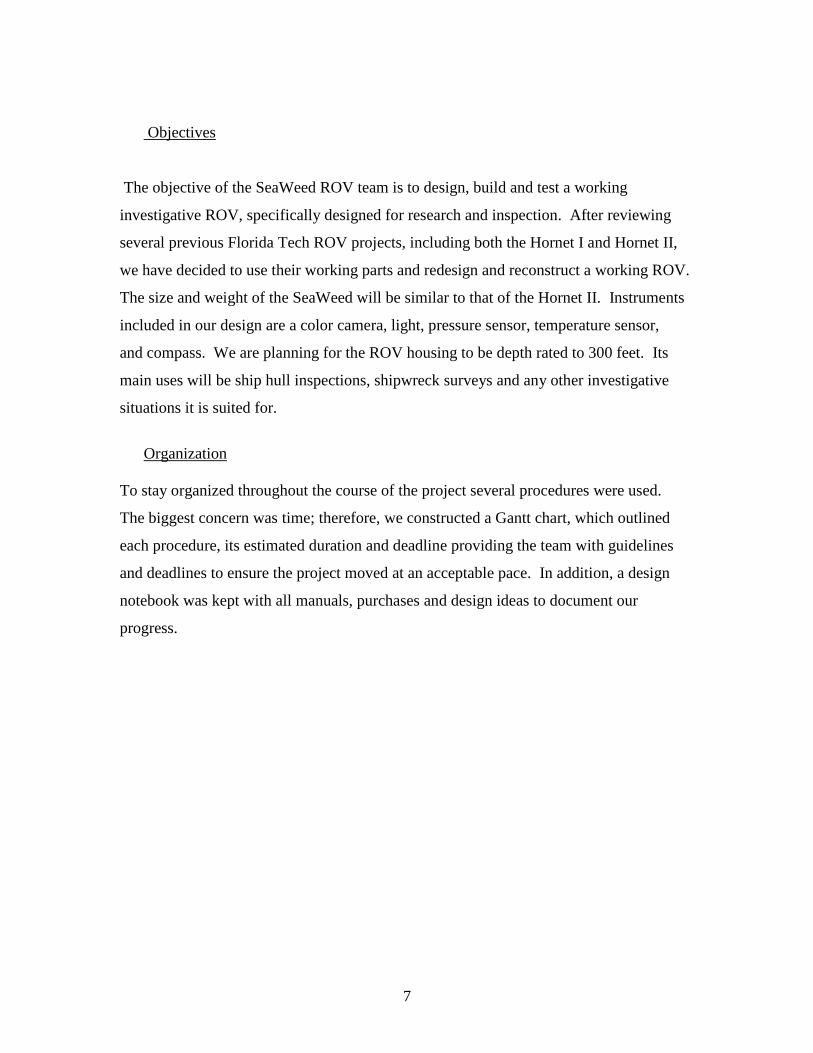
1. Introduction
Overview
Remotely operated vehicles are tethered, human operated, underwater robots used in the
marine industry for scientific and engineering purposes. The tether is both the best
and worst feature of an ROV. It can send unlimited power, video and other data signals
from the surface vessel to the ROV and send collected data back to the surface; however,
the drag the tether creates on the vehicle is immense, having very negative effects on
the efficiency and maneuverability of the vehicle. In order to minimize these effects most
ROV tethers, including the one used on SeaWeed, are neutrally buoyant and of small
diameter. (2)
The most basic ROV is a small observational vehicle equipped only with a light and
camera. The scientific and technological community however, tends to use ROV's of
much more complexity. Several features and additional equipment are incorporated into
the design to make the ROV more applicable. The most complex vehicles include
several subsystems that widen the range of use. ROV's began as engineering tools to
inspect pipelines and underwater structures utilizing manipulator arms and
magnetometers but have now crossed into the scientific realm by incorporating
oceanographic instruments such as CTD, water and sediment samplers, water quality
measurements, and even biological sampling. (3)
The U.S. Navy headed the increase in ROV development beginning in the 1960s. Since
then ROVs have been developed for several situations. For example, rescue ROVs
are designed to recover other vehicles and objects from the ocean floor; others are used in
the offshore oil and gas industry assisting the development of resource fields by
inspecting pipelines or making pipeline repairs; still others are used in ship hull
inspections and shipwreck exploration.
7
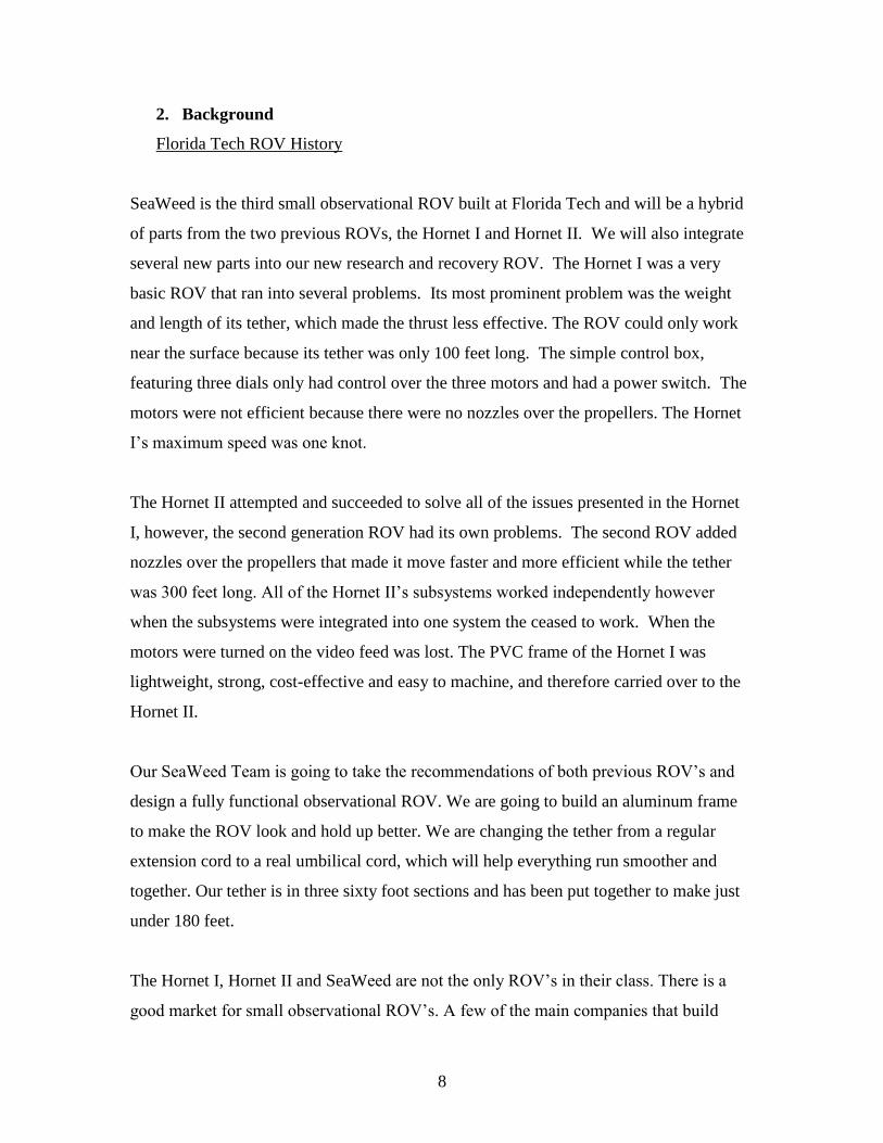
Objectives
The objective of the SeaWeed ROV team is to design, build and test a working
investigative ROV, specifically designed for research and inspection. After reviewing
several previous Florida Tech ROV projects, including both the Hornet I and Hornet II,
we have decided to use their working parts and redesign and reconstruct a working ROV.
The size and weight of the SeaWeed will be similar to that of the Hornet II. Instruments
included in our design are a color camera, light, pressure sensor, temperature sensor,
and compass. We are planning for the ROV housing to be depth rated to 300 feet. Its
main uses will be ship hull inspections, shipwreck surveys and any other investigative
situations it is suited for.
Organization
To stay organized throughout the course of the project several procedures were used.
The biggest concern was time; therefore, we constructed a Gantt chart, which outlined
each procedure, its estimated duration and deadline providing the team with guidelines
and deadlines to ensure the project moved at an acceptable pace. In addition, a design
notebook was kept with all manuals, purchases and design ideas to document our
progress.
8
2. Background
Florida Tech ROV History
SeaWeed is the third small observational ROV built at Florida Tech and will be a hybrid
of parts from the two previous ROVs, the Hornet I and Hornet II. We will also integrate
several new parts into our new research and recovery ROV. The Hornet I was a very
basic ROV that ran into several problems. Its most prominent problem was the weight
and length of its tether, which made the thrust less effective. The ROV could only work
near the surface because its tether was only 100 feet long. The simple control box,
featuring three dials only had control over the three motors and had a power switch. The
motors were not efficient because there were no nozzles over the propellers. The Hornet
I’s maximum speed was one knot.
The Hornet II attempted and succeeded to solve all of the issues presented in the Hornet
I, however, the second generation ROV had its own problems. The second ROV added
nozzles over the propellers that made it move faster and more efficient while the tether
was 300 feet long. All of the Hornet II’s subsystems worked independently however
when the subsystems were integrated into one system the ceased to work. When the
motors were turned on the video feed was lost. The PVC frame of the Hornet I was
lightweight, strong, cost-effective and easy to machine, and therefore carried over to the
Hornet II.
Our SeaWeed Team is going to take the recommendations of both previous ROV’s and
design a fully functional observational ROV. We are going to build an aluminum frame
to make the ROV look and hold up better. We are changing the tether from a regular
extension cord to a real umbilical cord, which will help everything run smoother and
together. Our tether is in three sixty foot sections and has been put together to make just
under 180 feet.
The Hornet I, Hornet II and SeaWeed are not the only ROV’s in their class. There is a
good market for small observational ROV’s. A few of the main companies that build
9
these include Video Ray, Shark marine, and Seabotix. Video Ray makes a Scout ROV
that includes a five-inch monitor, 131ft of tether, color camera and two lights. This Scout
model can cost up to 7,000 dollars. The ROVs designed and built by Florida Tech
undergraduates have all been under 2,500 including all donations.
Competitors
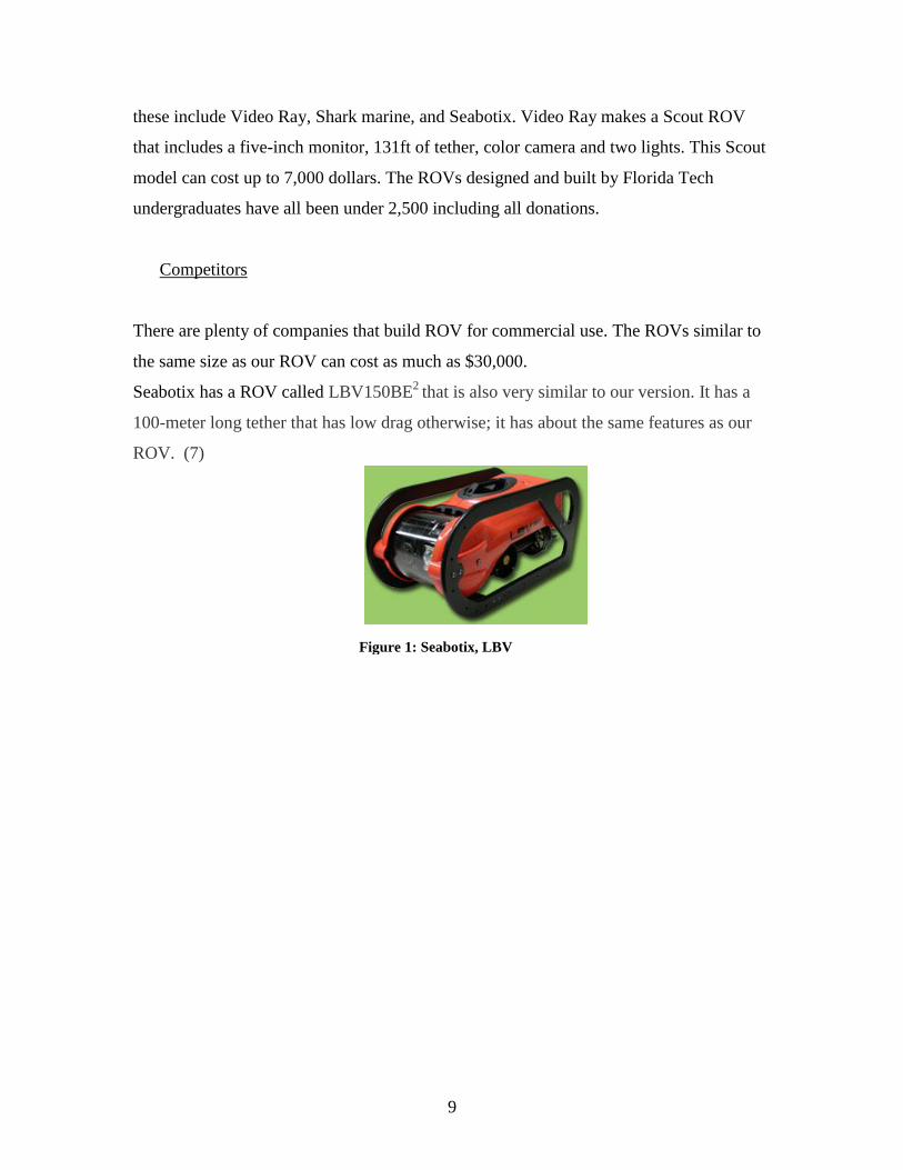
There are plenty of companies that build ROV for commercial use. The ROVs similar to
the same size as our ROV can cost as much as $30,000.
Seabotix has a ROV called LBV150BE2
that is also very similar to our version. It has a
100-meter long tether that has low drag otherwise; it has about the same features as our
ROV. (7)
Figure 1: Seabotix, LBV
10
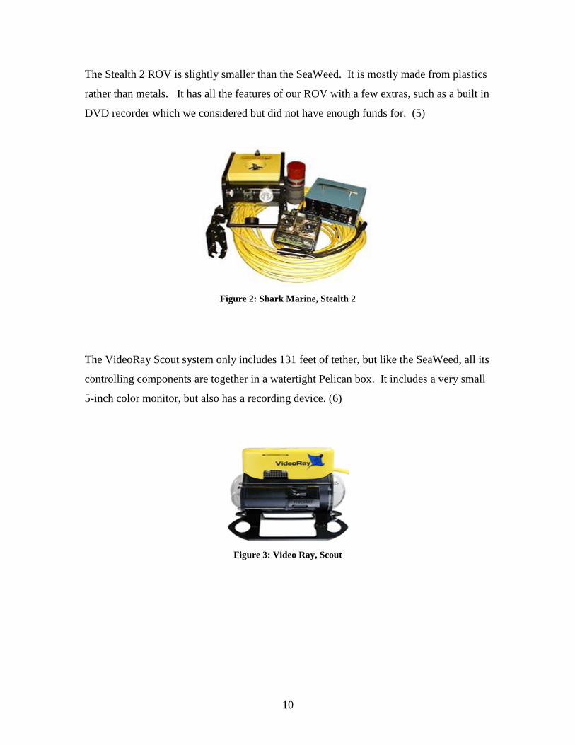
The Stealth 2 ROV is slightly smaller than the SeaWeed. It is mostly made from plastics
rather than metals. It has all the features of our ROV with a few extras, such as a built in
DVD recorder which we considered but did not have enough funds for. (5)
Figure 2: Shark Marine, Stealth 2
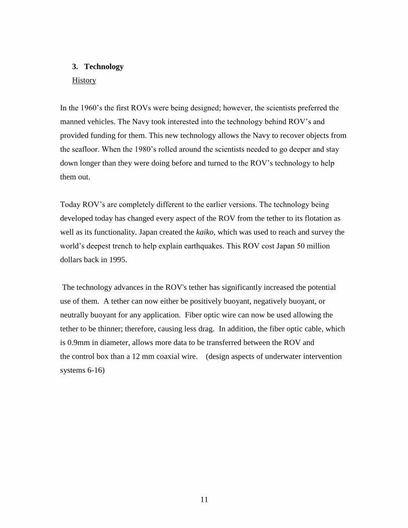
The VideoRay Scout system only includes 131 feet of tether, but like the SeaWeed, all its
controlling components are together in a watertight Pelican box. It includes a very small
5-inch color monitor, but also has a recording device. (6)
Figure 3: Video Ray, Scout
11
3. Technology
History
In the 1960’s the first ROVs were being designed; however, the scientists preferred the
manned vehicles. The Navy took interested into the technology behind ROV’s and
provided funding for them. This new technology allows the Navy to recover objects from
the seafloor. When the 1980’s rolled around the scientists needed to go deeper and stay
down longer than they were doing before and turned to the ROV’s technology to help
them out.
Today ROV’s are completely different to the earlier versions. The technology being
developed today has changed every aspect of the ROV from the tether to its flotation as
well as its functionality. Japan created the kaiko, which was used to reach and survey the
world’s deepest trench to help explain earthquakes. This ROV cost Japan 50 million
dollars back in 1995.
The technology advances in the ROV's tether has significantly increased the potential
use of them. A tether can now either be positively buoyant, negatively buoyant, or
neutrally buoyant for any application. Fiber optic wire can now be used allowing the
tether to be thinner; therefore, causing less drag. In addition, the fiber optic cable, which
is 0.9mm in diameter, allows more data to be transferred between the ROV and
the control box than a 12 mm coaxial wire. (design aspects of underwater intervention
systems 6-16)
12
4. Materials and Parts
Parts List
o Compass, Vector Electronics
o XBOB Video Overlay, Decade Engineering
o Pressure Transducer, Measurement Specialties, Inc.
o Flat Panel LCD TV, Polaroid
o Slimline HID MR11 (Dive Light), Dive Rite
o ROV Tether, Video Ray
o Acrylic Dome, Video Ray
o Slip Ring, MOOG Components Group
o Triple Axis Joystick, P3 America
o Tether Management System (Hose Reel)
o Control Box Connector, SealCon
o Connector, Seaconn
o Pelican Case
o Gas Spring and Brackets, Easylift Gas Springs of North America
o AC-DC Front End Converter, RO Associates, Inc.
o Microverter, RO Associates, Inc.
o Miscellaneous Electronics for Motor Controllers (see Purchase Orders)
o Motors, Servo Magnetics, Inc.
o Color Digital Camera, Polaris Industries
13
Parts and Materials Description
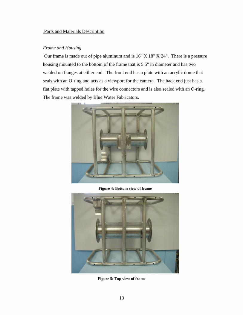
Frame and Housing
Our frame is made out of pipe aluminum and is 16" X 18" X 24". There is a pressure
housing mounted to the bottom of the frame that is 5.5" in diameter and has two
welded on flanges at either end. The front end has a plate with an acrylic dome that
seals with an O-ring and acts as a viewport for the camera. The back end just has a
flat plate with tapped holes for the wire connectors and is also sealed with an O-ring.
The frame was welded by Blue Water Fabricators.
Figure 4: Bottom view of frame
Figure 5: Top view of frame
14
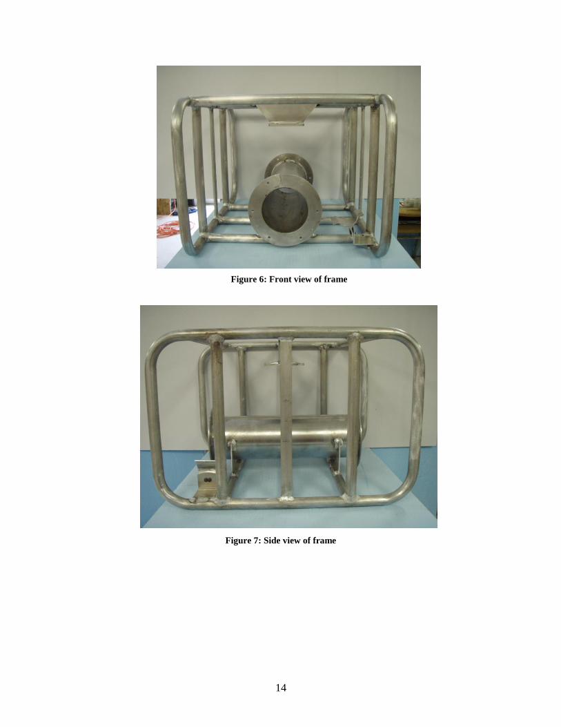
Figure 6: Front view of frame
Figure 7: Side view of frame
15
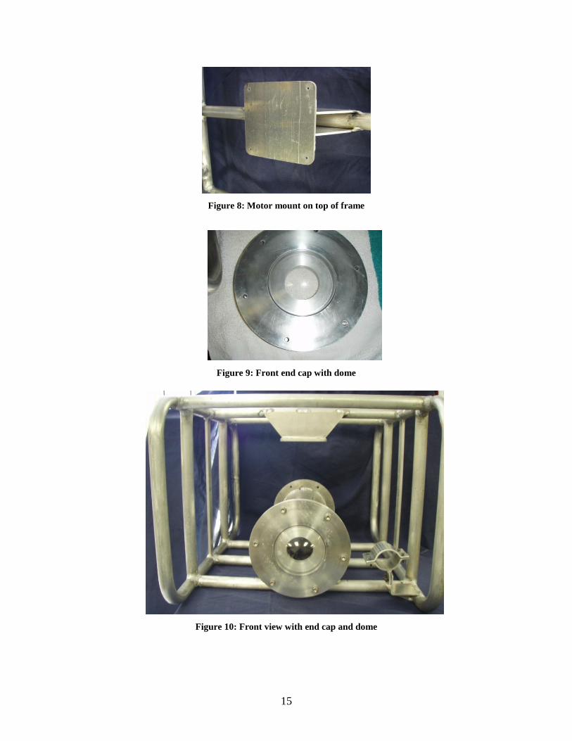
Figure 8: Motor mount on top of frame
Figure 9: Front end cap with dome
Figure 10: Front view with end cap and dome
16
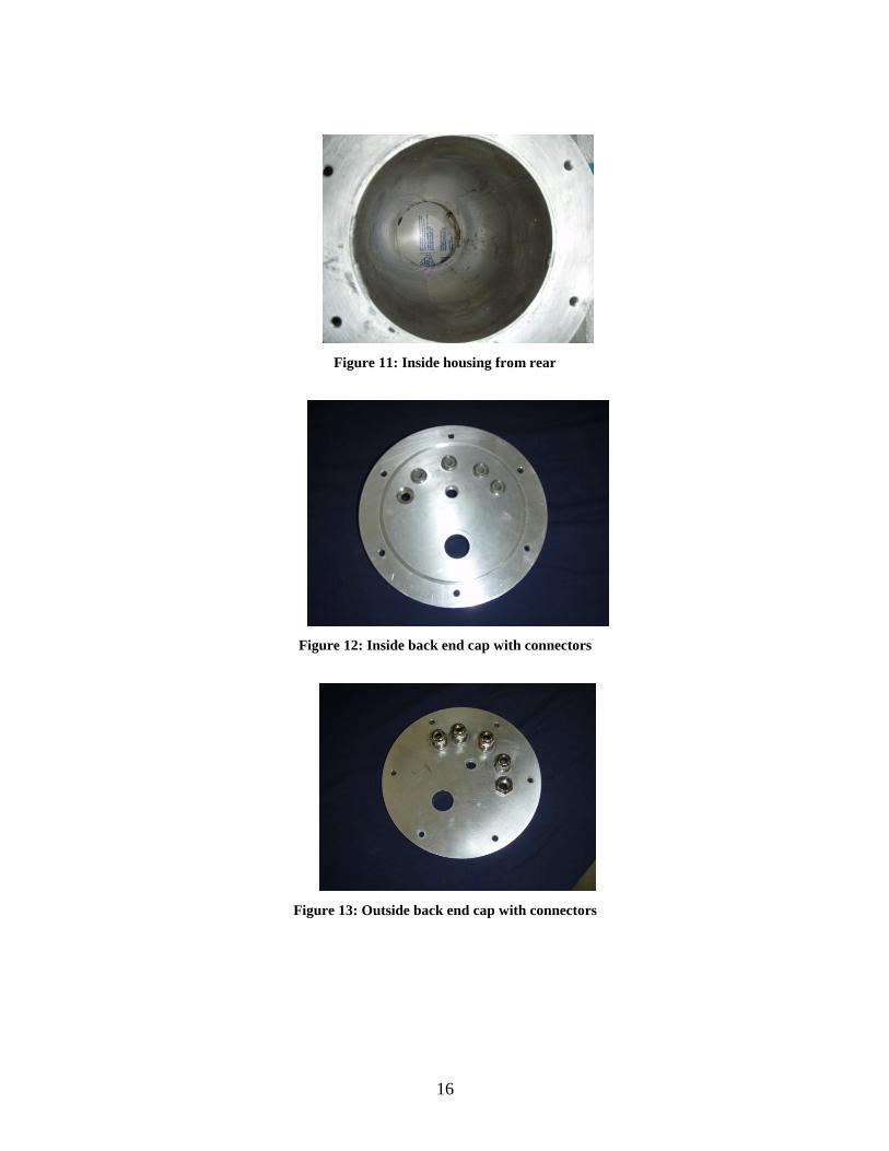
Figure 11: Inside housing from rear
Figure 12: Inside back end cap with connectors
Figure 13: Outside back end cap with connectors
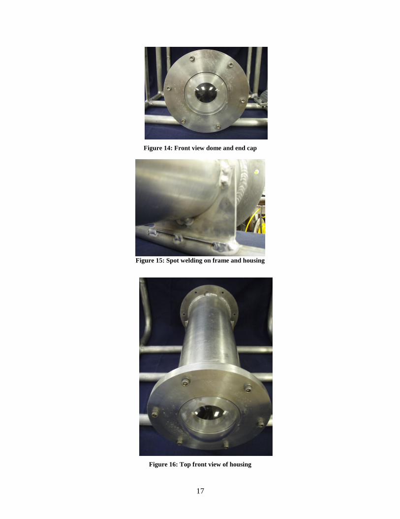
17
Figure 14: Front view dome and end cap
Figure 15: Spot welding on frame and housing
Figure 16: Top front view of housing
18
Pressure Sensor
The pressure sensor we are using was given to us by Dr. Wood. It can operate for -40
to 257 degrees Fahrenheit and it has a pressure range of 0-010 Bar. To accommodate
the pressure sensor in our ROV there is a tapped hole through the backside of the
pressure housing so the probed end can be in the water.
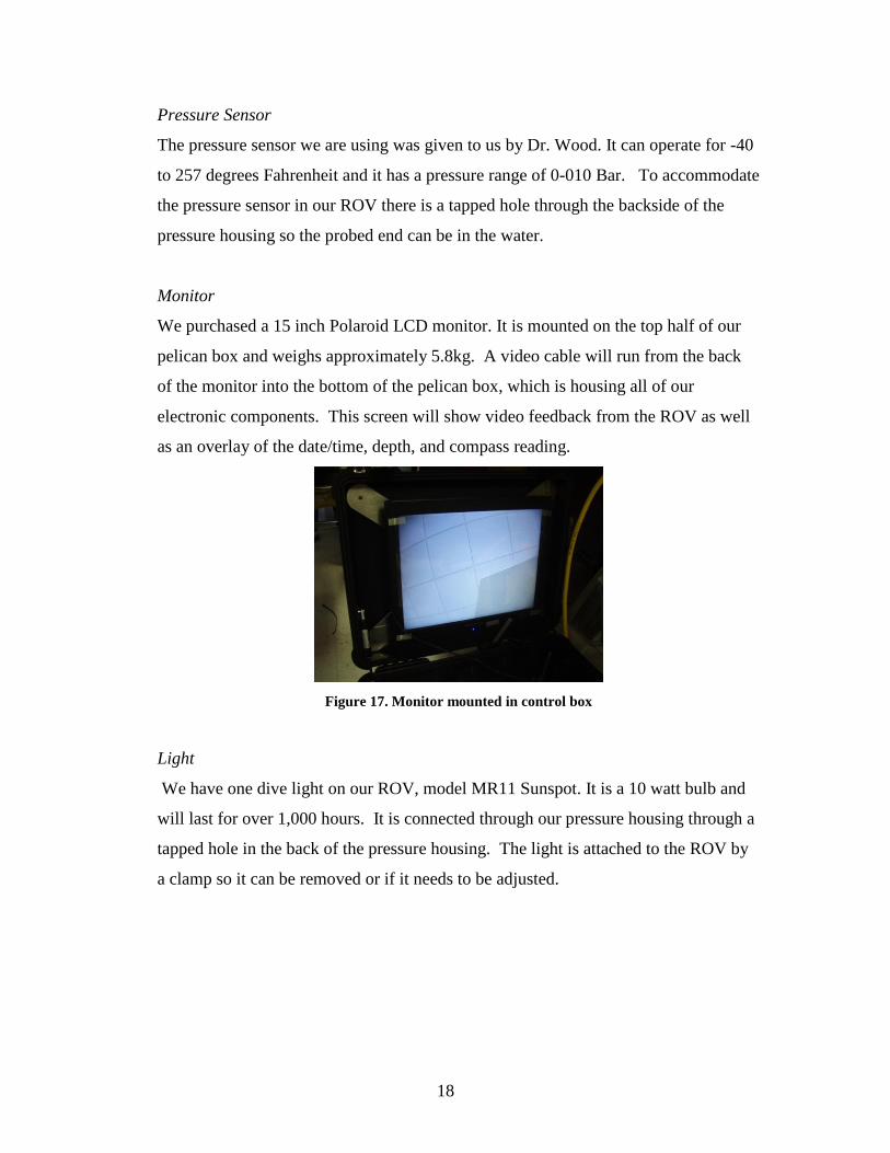
Monitor
We purchased a 15 inch Polaroid LCD monitor. It is mounted on the top half of our
pelican box and weighs approximately 5.8kg. A video cable will run from the back
of the monitor into the bottom of the pelican box, which is housing all of our
electronic components. This screen will show video feedback from the ROV as well
as an overlay of the date/time, depth, and compass reading.
Figure 17. Monitor mounted in control box
Light
We have one dive light on our ROV, model MR11 Sunspot. It is a 10 watt bulb and
will last for over 1,000 hours. It is connected through our pressure housing through a
tapped hole in the back of the pressure housing. The light is attached to the ROV by
a clamp so it can be removed or if it needs to be adjusted.
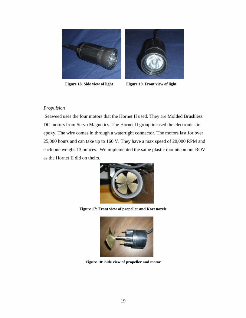
19
Figure 18. Side view of light Figure 19. Front view of light
Propulsion
Seaweed uses the four motors that the Hornet II used. They are Molded Brushless
DC motors from Servo Magnetics. The Hornet II group incased the electronics in
epoxy. The wire comes in through a watertight connector. The motors last for over
25,000 hours and can take up to 160 V. They have a max speed of 20,000 RPM and
each one weighs 13 ounces. We implemented the same plastic mounts on our ROV
as the Hornet II did on theirs.
Figure 17: Front view of propeller and Kort nozzle
Figure 18: Side view of propeller and motor
20
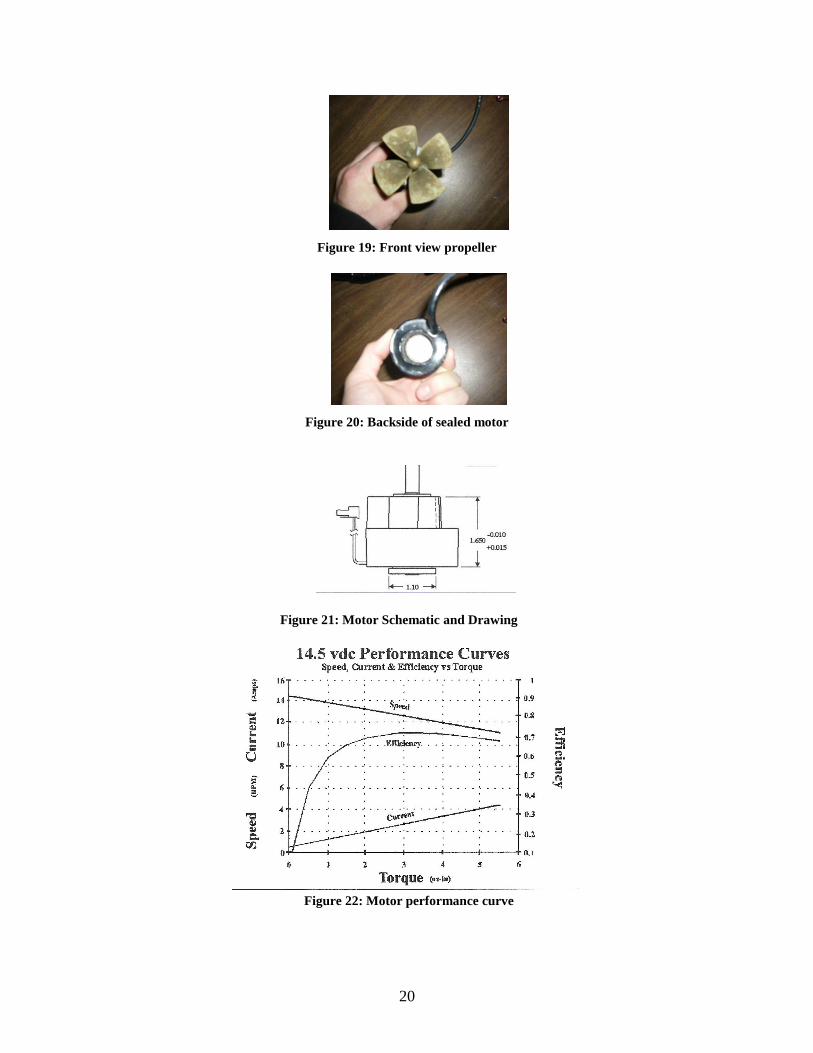
Figure 19: Front view propeller
Figure 20: Backside of sealed motor
Figure 21: Motor Schematic and Drawing
Figure 22: Motor performance curve
21
Kort Nozzle
We are using the same type 37 Kort Nozzles as the Hornet II. They chose these
nozzles because of its performance. They are made from plastic and have three
stainless steel screws holding them in place.
Figure 23: Front view Kort nozzle
Figure 24: Side view Kort nozzle
Figure 25: Kort nozzle chart
22
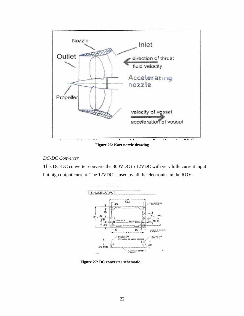
Figure 26: Kort nozzle drawing
DC-DC Converter
This DC-DC converter converts the 300VDC to 12VDC with very little current input
but high output current. The 12VDC is used by all the electronics in the ROV.
Figure 27: DC converter schematic
23
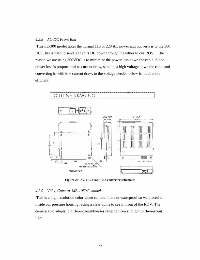
4.2.8 AC-DC Front End
This FE-300 model takes the normal 110 or 220 AC power and converts is to the 300
DC. This is used to send 300 volts DC down through the tether to our ROV. . The
reason we are using 300VDC is to minimize the power loss down the cable. Since
power loss is proportional to current draw, sending a high voltage down the cable and
converting it, with low current draw, to the voltage needed below is much more
efficient
Figure 28: AC-DC Front End converter schematic
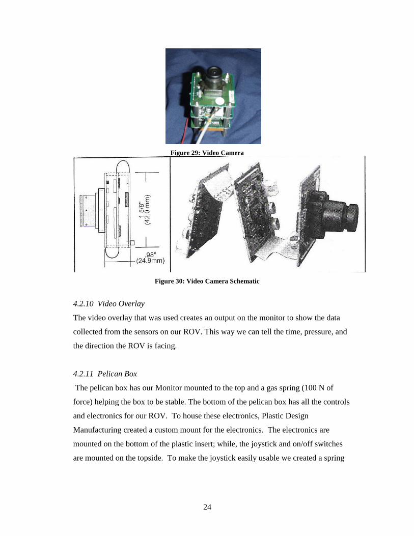
4.2.9 Video Camera MB-1050C model
This is a high resolution color video camera. It is not waterproof so we placed it
inside our pressure housing facing a clear dome to see in front of the ROV. The
camera auto adapts to different brightnesses ranging from sunlight to fluorescent
light.
24
Figure 29: Video Camera
Figure 30: Video Camera Schematic
4.2.10 Video Overlay
The video overlay that was used creates an output on the monitor to show the data
collected from the sensors on our ROV. This way we can tell the time, pressure, and
the direction the ROV is facing.
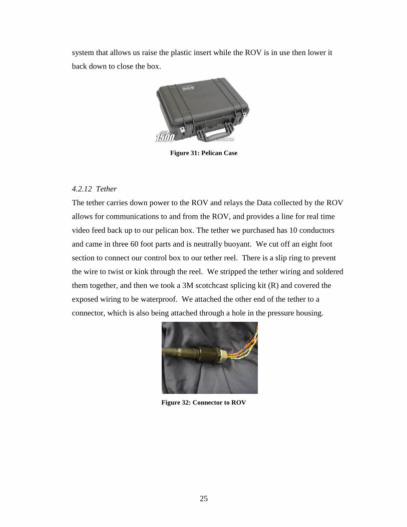
4.2.11 Pelican Box
The pelican box has our Monitor mounted to the top and a gas spring (100 N of
force) helping the box to be stable. The bottom of the pelican box has all the controls
and electronics for our ROV. To house these electronics, Plastic Design
Manufacturing created a custom mount for the electronics. The electronics are
mounted on the bottom of the plastic insert; while, the joystick and on/off switches
are mounted on the topside. To make the joystick easily usable we created a spring
25
system that allows us raise the plastic insert while the ROV is in use then lower it
back down to close the box.
Figure 31: Pelican Case
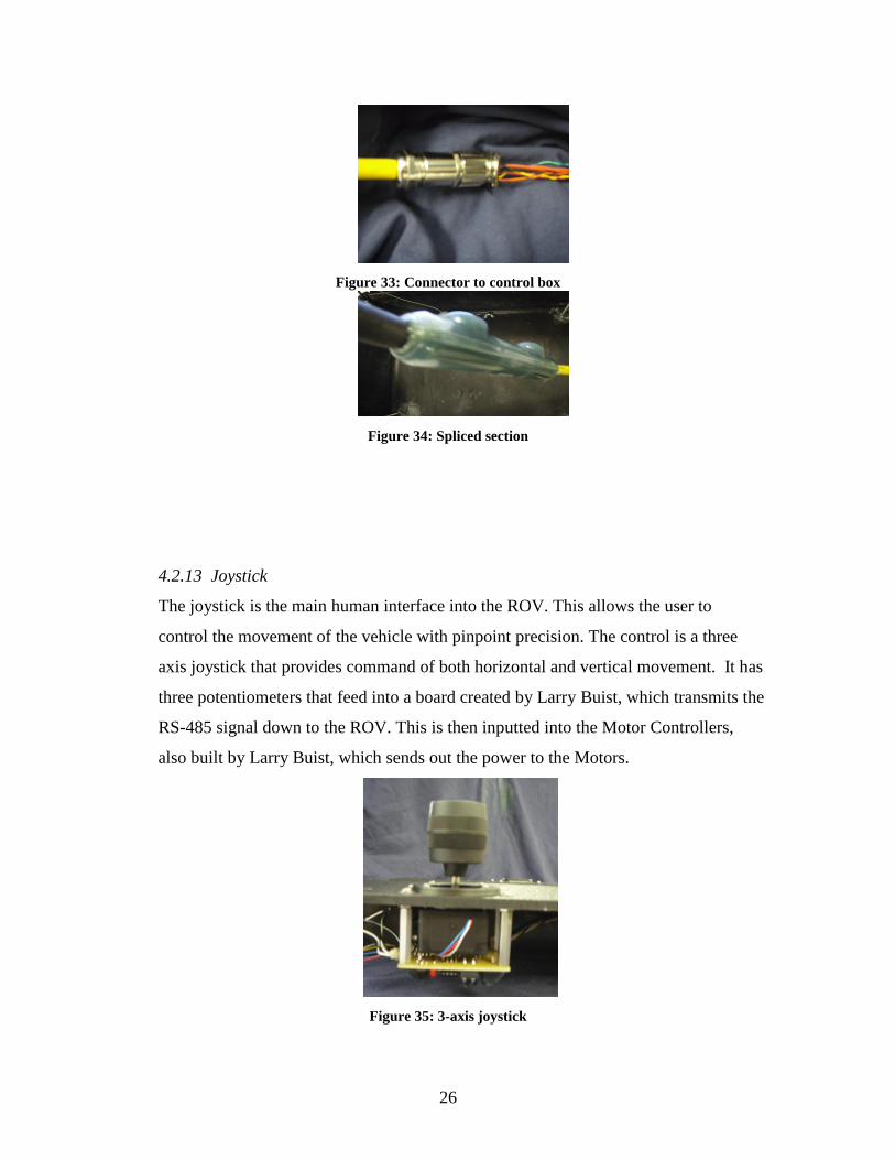
4.2.12 Tether
The tether carries down power to the ROV and relays the Data collected by the ROV
allows for communications to and from the ROV, and provides a line for real time
video feed back up to our pelican box. The tether we purchased has 10 conductors
and came in three 60 foot parts and is neutrally buoyant. We cut off an eight foot
section to connect our control box to our tether reel. There is a slip ring to prevent
the wire to twist or kink through the reel. We stripped the tether wiring and soldered
them together, and then we took a 3M scotchcast splicing kit (R) and covered the
exposed wiring to be waterproof. We attached the other end of the tether to a
connector, which is also being attached through a hole in the pressure housing.
Figure 32: Connector to ROV
26
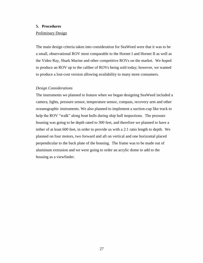
Figure 33: Connector to control box
Figure 34: Spliced section
4.2.13 Joystick
The joystick is the main human interface into the ROV. This allows the user to
control the movement of the vehicle with pinpoint precision. The control is a three
axis joystick that provides command of both horizontal and vertical movement. It has
three potentiometers that feed into a board created by Larry Buist, which transmits the
RS-485 signal down to the ROV. This is then inputted into the Motor Controllers,
also built by Larry Buist, which sends out the power to the Motors.
Figure 35: 3-axis joystick
27
5. Procedures
Preliminary Design
The main design criteria taken into consideration for SeaWeed were that it was to be
a small, observational ROV most comparable to the Hornet I and Hornet II as well as
the Video Ray, Shark Marine and other competitive ROVs on the market. We hoped
to produce an ROV up to the caliber of ROVs being sold today; however, we wanted
to produce a lost-cost version allowing availability to many more consumers.
Design Considerations
The instruments we planned to feature when we began designing SeaWeed included a
camera, lights, pressure sensor, temperature sensor, compass, recovery arm and other
oceanographic instruments. We also planned to implement a suction-cup like track to
help the ROV “walk” along boat hulls during ship hull inspections. The pressure
housing was going to be depth rated to 300 feet, and therefore we planned to have a
tether of at least 600 feet, in order to provide us with a 2:1 ratio length to depth. We
planned on four motors, two forward and aft on vertical and one horizontal placed
perpendicular to the back plate of the housing. The frame was to be made out of
aluminum extrusion and we were going to order an acrylic dome to add to the
housing as a viewfinder.
28
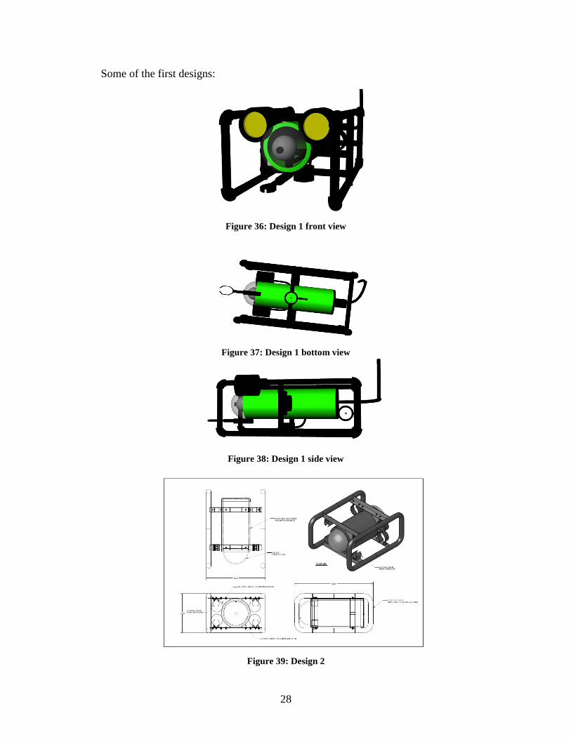
Some of the first designs:
Figure 36: Design 1 front view
Figure 37: Design 1 bottom view
Figure 38: Design 1 side view
Figure 39: Design 2
29
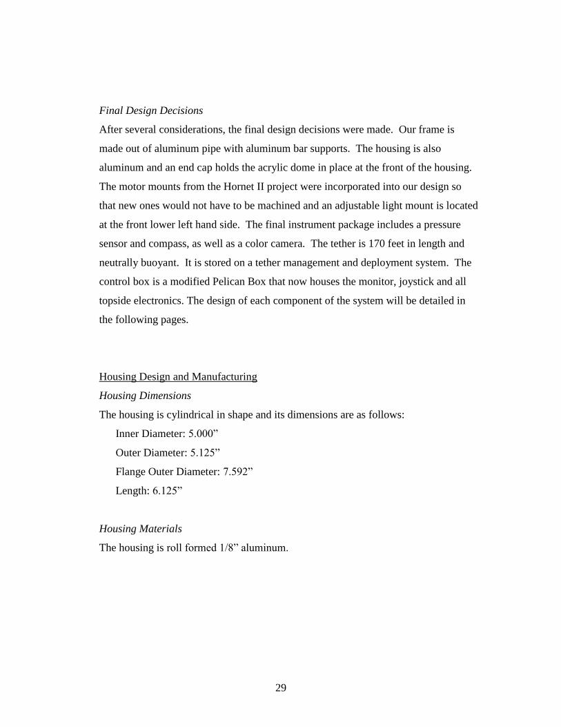
Final Design Decisions
After several considerations, the final design decisions were made. Our frame is
made out of aluminum pipe with aluminum bar supports. The housing is also
aluminum and an end cap holds the acrylic dome in place at the front of the housing.
The motor mounts from the Hornet II project were incorporated into our design so
that new ones would not have to be machined and an adjustable light mount is located
at the front lower left hand side. The final instrument package includes a pressure
sensor and compass, as well as a color camera. The tether is 170 feet in length and
neutrally buoyant. It is stored on a tether management and deployment system. The
control box is a modified Pelican Box that now houses the monitor, joystick and all
topside electronics. The design of each component of the system will be detailed in
the following pages.
Housing Design and Manufacturing
Housing Dimensions
The housing is cylindrical in shape and its dimensions are as follows:
Inner Diameter: 5.000”
Outer Diameter: 5.125”
Flange Outer Diameter: 7.592”
Length: 6.125”
Housing Materials
The housing is roll formed 1/8” aluminum.
30
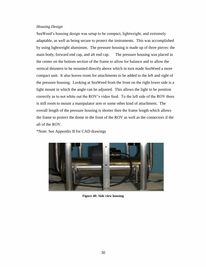
Housing Design
SeaWeed’s housing design was setup to be compact, lightweight, and extremely
adaptable, as well as being secure to protect the instruments. This was accomplished
by using lightweight aluminum. The pressure housing is made up of three pieces: the
main body, forward end cap, and aft end cap. The pressure housing was placed in
the center on the bottom section of the frame to allow for balance and to allow the
vertical thrusters to be mounted directly above which in turn made SeaWeed a more
compact unit. It also leaves room for attachments to be added to the left and right of
the pressure housing. Looking at SeaWeed from the front on the right lower side is a
light mount in which the angle can be adjusted. This allows the light to be position
correctly as to not white out the ROV’s video feed. To the left side of the ROV there
is still room to mount a manipulator arm or some other kind of attachment. The
overall length of the pressure housing is shorter then the frame length which allows
the frame to protect the dome in the front of the ROV as well as the connectors if the
aft of the ROV.
*Note: See Appendix B for CAD drawings
Figure 40: Side view housing
31
Outer Housing
The housing is 1/8” roll formed aluminum with two flanges welded on either end to
support the end caps. The forward flange has a raised circular center in which the
acrylic dome sits over. The forward end cap is a ¼” piece of circular aluminum that
has a hole in the center to allow the dome to slide through. It also has holes drilled
around the outer edge to match those of the forward flange to slide bolts through to
tighten the end cap down allowing it to become watertight. The aft end cap is a solid
piece of aluminum but has six holes drilled in the center area with through hole
connects. These connectors are for the four motors, one light, one pressure sensor
and one for the tether. There is also holes drill around the perimeter, which match the
holes on the aft flange to allow fasteners to slide through to enable the end cap to
tighten down and become watertight.
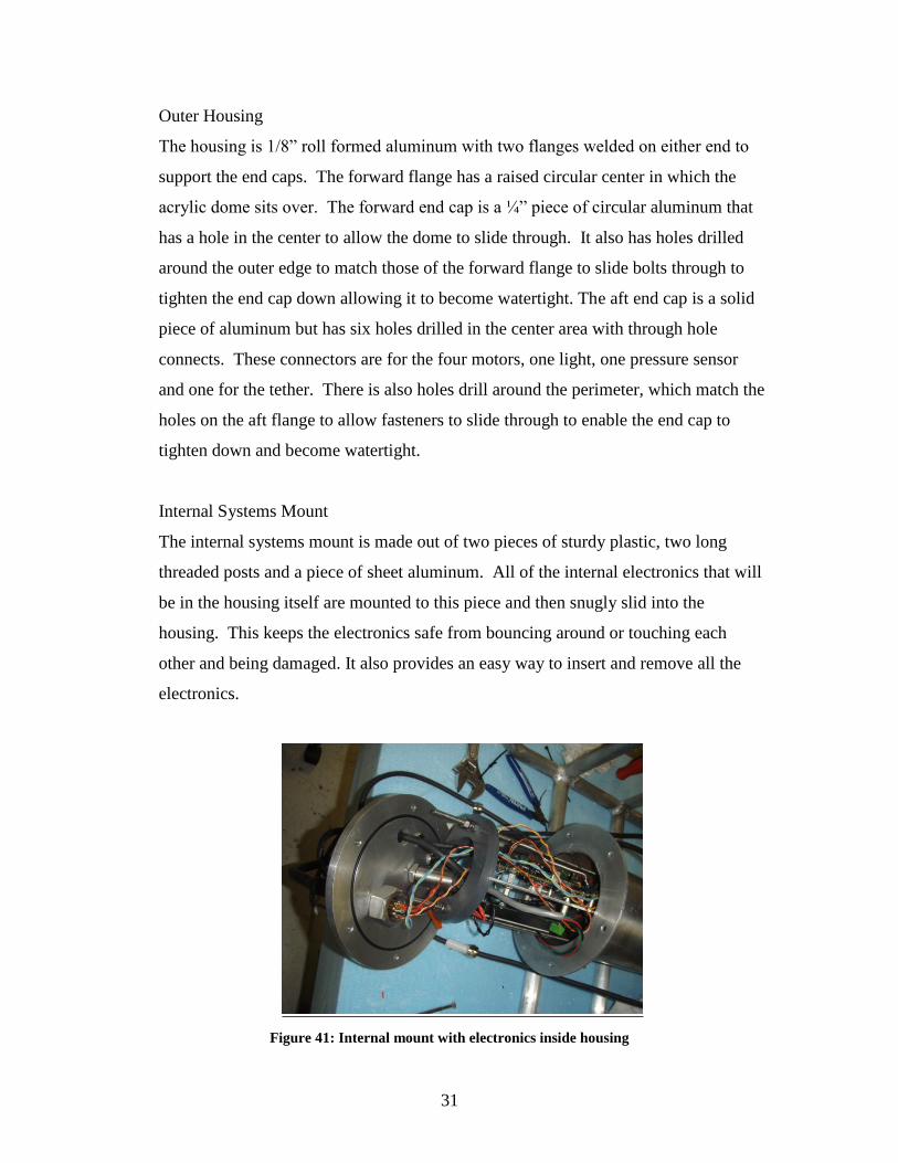
Internal Systems Mount
The internal systems mount is made out of two pieces of sturdy plastic, two long
threaded posts and a piece of sheet aluminum. All of the internal electronics that will
be in the housing itself are mounted to this piece and then snugly slid into the
housing. This keeps the electronics safe from bouncing around or touching each
other and being damaged. It also provides an easy way to insert and remove all the
electronics.
Figure 41: Internal mount with electronics inside housing
32
Housing Manufacturing
We collaborated with Alliance Tool and Machine, Co. to have the housing and end
caps manufactured. After some discussion, we realized a few modifications were
needed. Ed Robbins, from Robbins welding continued working on the housing and
welded an end cap for us. He also drilled the holes needed for all the connectors into
the back end cap. The front cap has a radial O-ring seal against the dome and an end
cap to apply pressure. The back end cap has an O-ring face seal and pressure is
applied with six bolts.
Frame Design and Manufacturing
Frame Dimensions
The frame dimensions are as follows:
Length: 24 inches
Height: 16 inches
Width: 20 inches
Frame Materials
The frame was made out of 1-inch outer diameter, 1/8 inch wall thickness aluminum
tubing. There are also pieces of 1/8 inch aluminum bar for supports and mounts. We
chose aluminum because it is lightweight, durable and easy to access.
Frame Design
Our main design criteria were dimensions, weight and feasibility. We wanted to the
frame to be lightweight and durable, so we chose marine grade aluminum as the
material. Several designs were created, however the basic shape and size have been
consistent throughout the entire design process. We kept a lot of room for extra
flotation and other instruments by mounting the housing at the bottom of the frame.
This will also keep the vehicle more stable.
*Note: CAD Drawings can be found in Appendix C
33
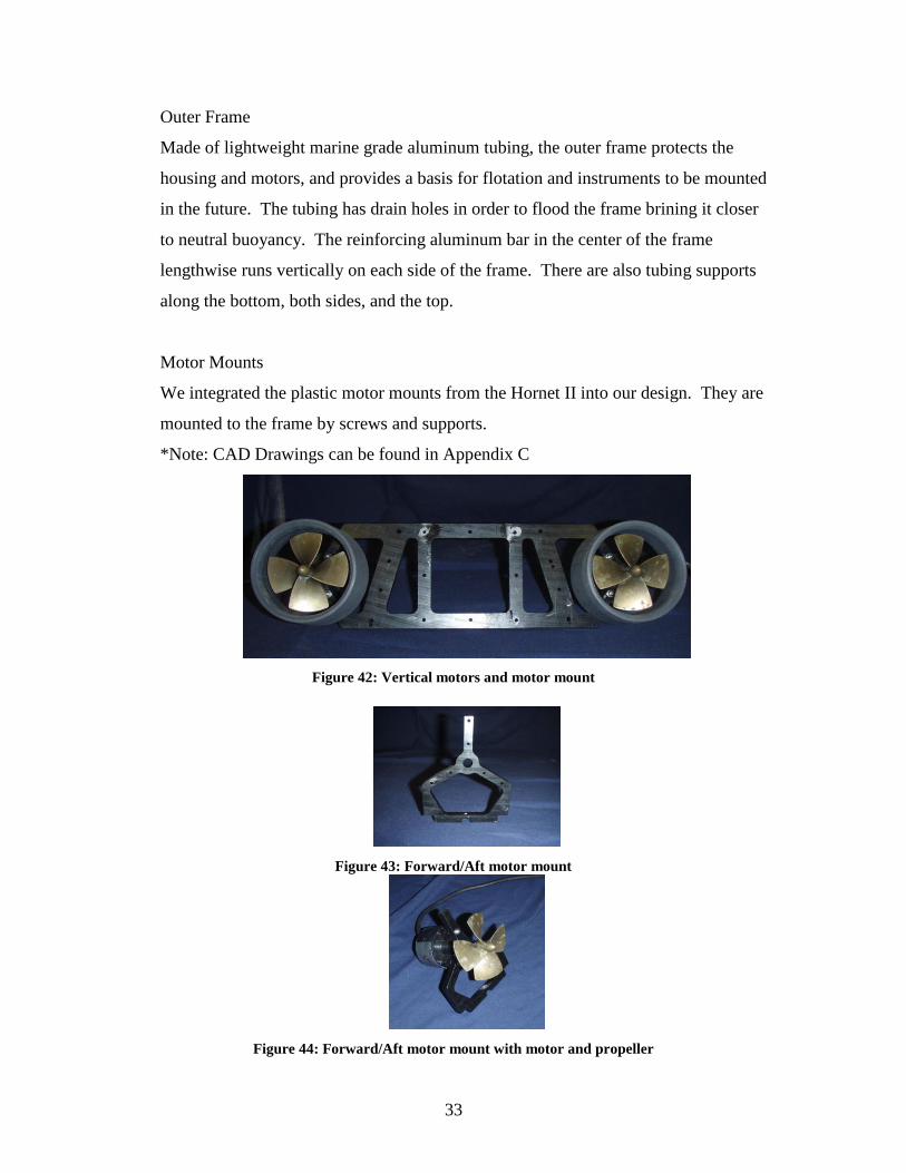
Outer Frame
Made of lightweight marine grade aluminum tubing, the outer frame protects the
housing and motors, and provides a basis for flotation and instruments to be mounted
in the future. The tubing has drain holes in order to flood the frame brining it closer
to neutral buoyancy. The reinforcing aluminum bar in the center of the frame
lengthwise runs vertically on each side of the frame. There are also tubing supports
along the bottom, both sides, and the top.
Motor Mounts
We integrated the plastic motor mounts from the Hornet II into our design. They are
mounted to the frame by screws and supports.
*Note: CAD Drawings can be found in Appendix C
Figure 42: Vertical motors and motor mount
Figure 43: Forward/Aft motor mount
Figure 44: Forward/Aft motor mount with motor and propeller
34
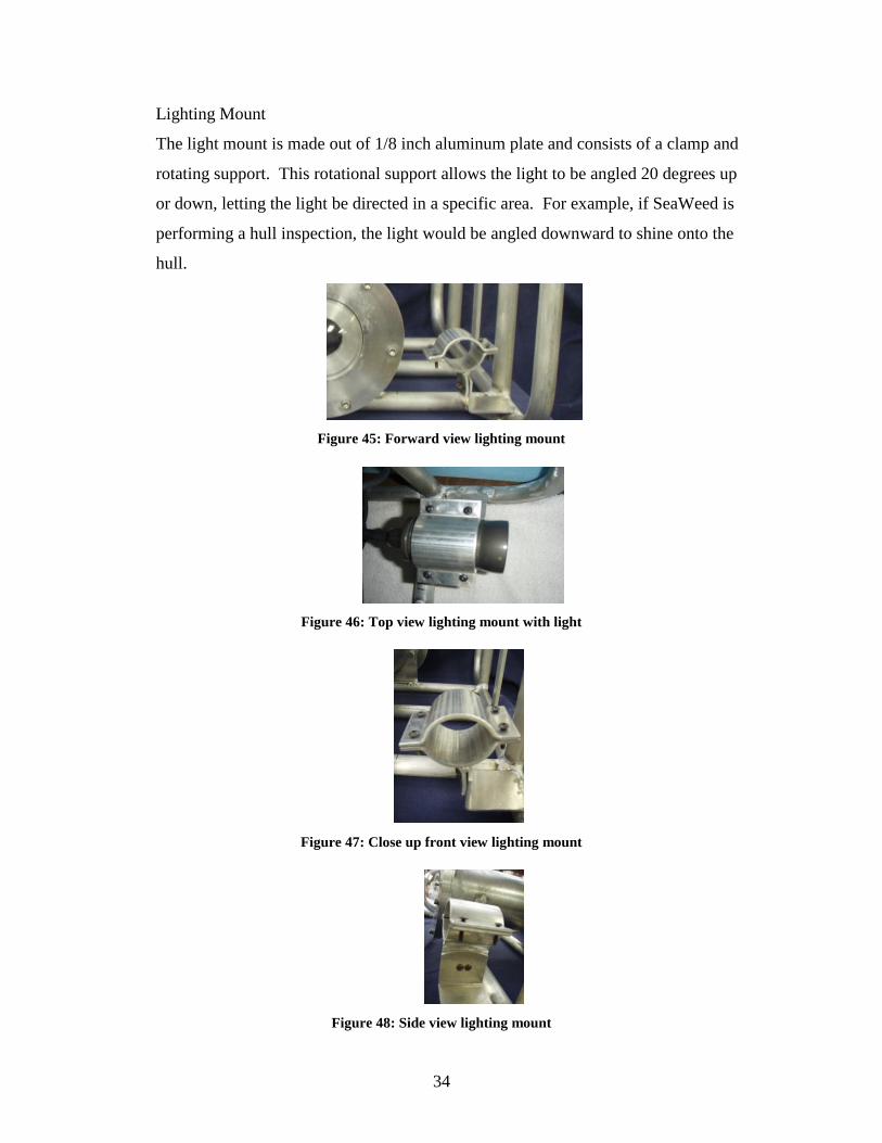
Lighting Mount
The light mount is made out of 1/8 inch aluminum plate and consists of a clamp and
rotating support. This rotational support allows the light to be angled 20 degrees up
or down, letting the light be directed in a specific area. For example, if SeaWeed is
performing a hull inspection, the light would be angled downward to shine onto the
hull.
Figure 45: Forward view lighting mount
Figure 46: Top view lighting mount with light
Figure 47: Close up front view lighting mount
Figure 48: Side view lighting mount
35
Frame Manufacturing
The frame was a team effort between the SeaWeed ROV team, contact Tom Dobek
with Repair Industries of Michigan and their sub-contractor Blue Water Fabricators.
We had several design meetings with both companies to decide on a final design.
They provided all the materials and manufacturing for the frame.
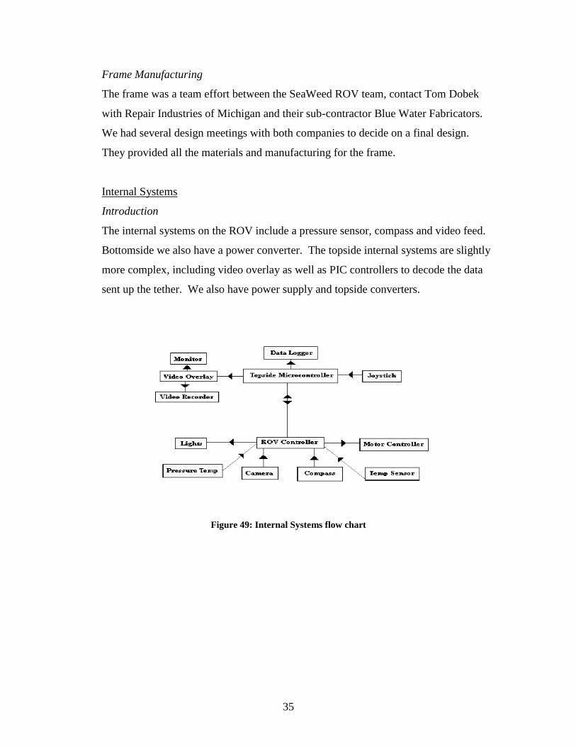
Internal Systems
Introduction
The internal systems on the ROV include a pressure sensor, compass and video feed.
Bottomside we also have a power converter. The topside internal systems are slightly
more complex, including video overlay as well as PIC controllers to decode the data
sent up the tether. We also have power supply and topside converters.
Figure 49: Internal Systems flow chart
36
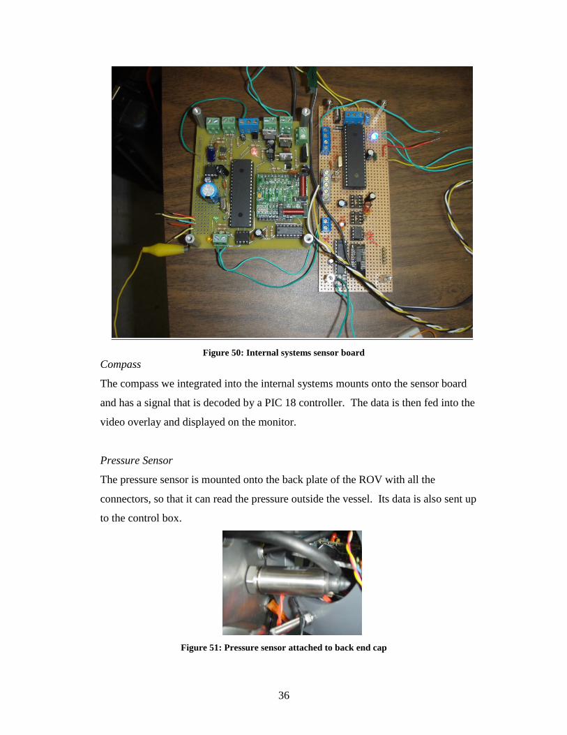
Figure 50: Internal systems sensor board
Compass
The compass we integrated into the internal systems mounts onto the sensor board
and has a signal that is decoded by a PIC 18 controller. The data is then fed into the
video overlay and displayed on the monitor.
Pressure Sensor
The pressure sensor is mounted onto the back plate of the ROV with all the
connectors, so that it can read the pressure outside the vessel. Its data is also sent up
to the control box.
Figure 51: Pressure sensor attached to back end cap
37
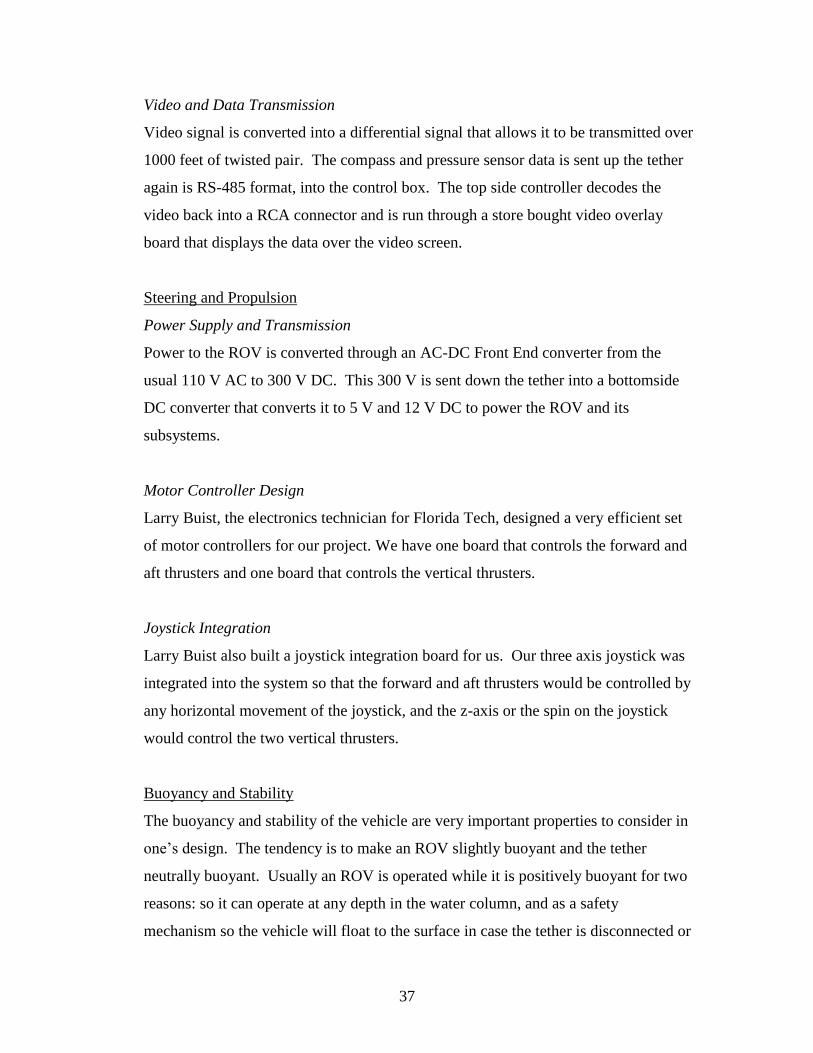
Video and Data Transmission
Video signal is converted into a differential signal that allows it to be transmitted over
1000 feet of twisted pair. The compass and pressure sensor data is sent up the tether
again is RS-485 format, into the control box. The top side controller decodes the
video back into a RCA connector and is run through a store bought video overlay
board that displays the data over the video screen.
Steering and Propulsion
Power Supply and Transmission
Power to the ROV is converted through an AC-DC Front End converter from the
usual 110 V AC to 300 V DC. This 300 V is sent down the tether into a bottomside
DC converter that converts it to 5 V and 12 V DC to power the ROV and its
subsystems.
Motor Controller Design
Larry Buist, the electronics technician for Florida Tech, designed a very efficient set
of motor controllers for our project. We have one board that controls the forward and
aft thrusters and one board that controls the vertical thrusters.
Joystick Integration
Larry Buist also built a joystick integration board for us. Our three axis joystick was
integrated into the system so that the forward and aft thrusters would be controlled by
any horizontal movement of the joystick, and the z-axis or the spin on the joystick
would control the two vertical thrusters.
Buoyancy and Stability
The buoyancy and stability of the vehicle are very important properties to consider in
one’s design. The tendency is to make an ROV slightly buoyant and the tether
neutrally buoyant. Usually an ROV is operated while it is positively buoyant for two
reasons: so it can operate at any depth in the water column, and as a safety
mechanism so the vehicle will float to the surface in case the tether is disconnected or
38
power is lost. As a rule of thumb, smaller vehicles like the SeaWeed require
approximately 5 pounds of buoyancy. (4)
Syntactic Foam
We plan to use donated syntactic foam for our floatation on the vehicle.
Syntactic foams are composites made by filling metal, ceramic or polymer matrix
with hollow microballoons, usually glass.
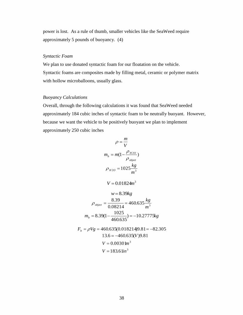
Buoyancy Calculations
Overall, through the following calculations it was found that SeaWeed needed
approximately 184 cubic inches of syntactic foam to be neutrally buoyant. However,
because we want the vehicle to be positively buoyant we plan to implement
approximately 250 cubic inches
V
m
)1( 2
object
OH
b mm
32 1025m
kgOH
301824.0 mV kgw 39.8
3635.460
08214.0
39.8
m
kgobject
kgmb 27775.10)635.460
10251(39.8
305.8281.9)018214.0(635.460 VgFb
3
3
61.183
00301.0
81.9)(635.4606.13
inV
mV
V
39
Control Box Design
The goal of SeaWeed’s Control box was to have a single unit that was very
streamline and compact. The whole control system is boxed inside a watertight
Pelican box, which allows for stowage outside on a ships deck when not in use In the
middle of the control panel it sinks in to allow for the holding cables as well as
manuals for the ROV itself. When the ROV is not in use the Pelican box lid can be
shut and latched, allowing the internal parts of the Control Box to be seal from the
elements.
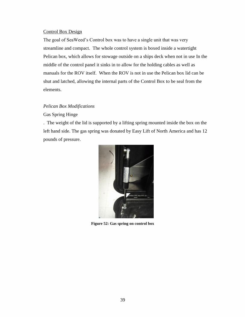
Pelican Box Modifications
Gas Spring Hinge
. The weight of the lid is supported by a lifting spring mounted inside the box on the
left hand side. The gas spring was donated by Easy Lift of North America and has 12
pounds of pressure.
Figure 52: Gas spring on control box
40
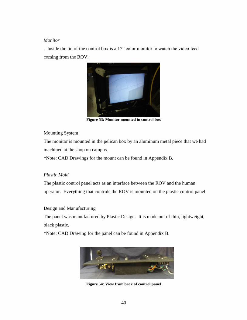
Monitor
. Inside the lid of the control box is a 17” color monitor to watch the video feed
coming from the ROV.
Figure 53: Monitor mounted in control box
Mounting System
The monitor is mounted in the pelican box by an aluminum metal piece that we had
machined at the shop on campus.
*Note: CAD Drawings for the mount can be found in Appendix B.
Plastic Mold
The plastic control panel acts as an interface between the ROV and the human
operator. Everything that controls the ROV is mounted on the plastic control panel.
Design and Manufacturing
The panel was manufactured by Plastic Design. It is made out of thin, lightweight,
black plastic.
*Note: CAD Drawing for the panel can be found in Appendix B.
Figure 54: View from back of control panel
41
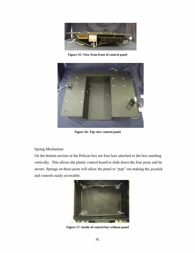
Figure 55: View from front of control panel
Figure 56: Top view control panel
Spring Mechanism
On the bottom section of the Pelican box are four bars attached to the box standing
vertically. This allows the plastic control board to slide down the four posts and be
secure. Springs on these posts will allow the panel to “pop” out making the joystick
and controls easily accessible.
Figure 57: Inside of control box without panel
42
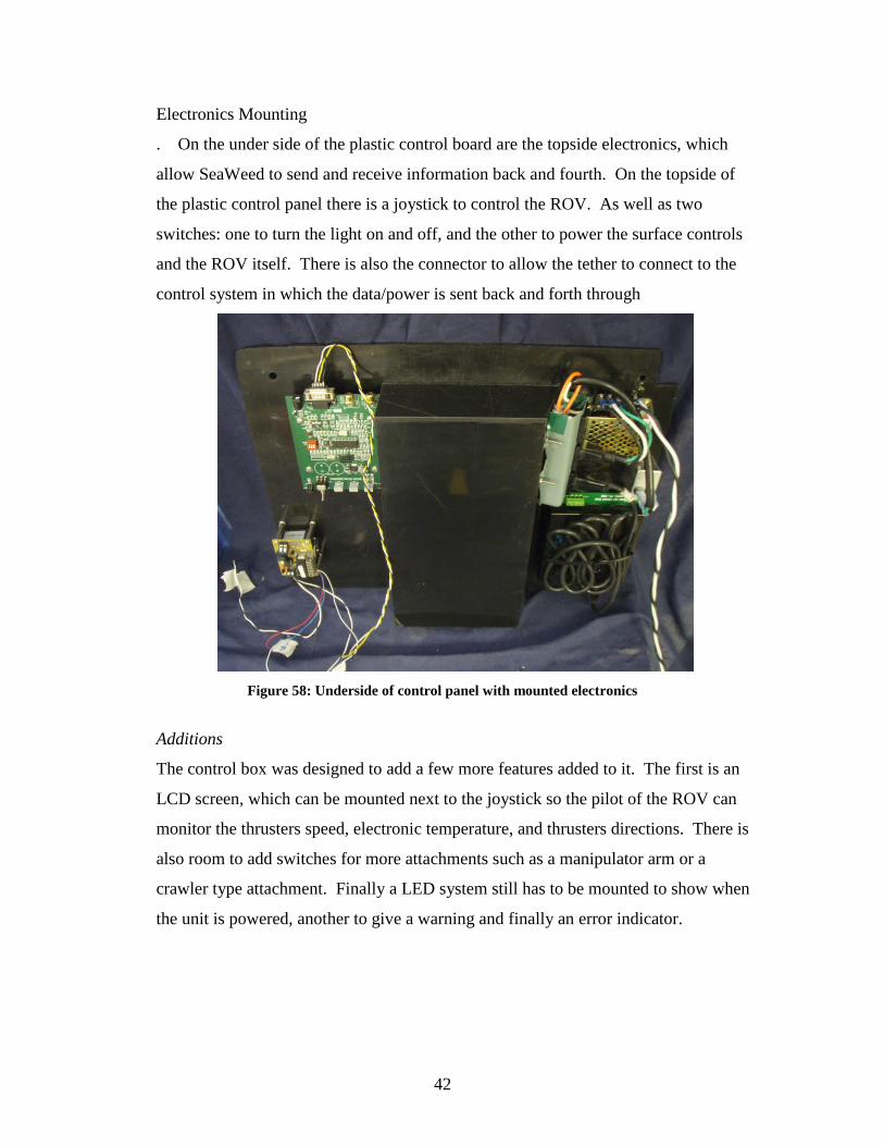
Electronics Mounting
. On the under side of the plastic control board are the topside electronics, which
allow SeaWeed to send and receive information back and fourth. On the topside of
the plastic control panel there is a joystick to control the ROV. As well as two
switches: one to turn the light on and off, and the other to power the surface controls
and the ROV itself. There is also the connector to allow the tether to connect to the
control system in which the data/power is sent back and forth through
Figure 58: Underside of control panel with mounted electronics
Additions
The control box was designed to add a few more features added to it. The first is an
LCD screen, which can be mounted next to the joystick so the pilot of the ROV can
monitor the thrusters speed, electronic temperature, and thrusters directions. There is
also room to add switches for more attachments such as a manipulator arm or a
crawler type attachment. Finally a LED system still has to be mounted to show when
the unit is powered, another to give a warning and finally an error indicator.
43
Tether Modifications and Tether Management System Design
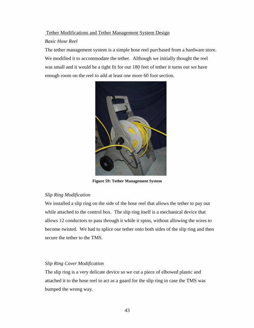
Basic Hose Reel
The tether management system is a simple hose reel purchased from a hardware store.
We modified it to accommodate the tether. Although we initially thought the reel
was small and it would be a tight fit for our 180 feet of tether it turns out we have
enough room on the reel to add at least one more 60 foot section.
Figure 59: Tether Management System
Slip Ring Modification
We installed a slip ring on the side of the hose reel that allows the tether to pay out
while attached to the control box. The slip ring itself is a mechanical device that
allows 12 conductors to pass through it while it spins, without allowing the wires to
become twisted. We had to splice our tether onto both sides of the slip ring and then
secure the tether to the TMS.
Slip Ring Cover Modification
The slip ring is a very delicate device so we cut a piece of elbowed plastic and
attached it to the hose reel to act as a guard for the slip ring in case the TMS was
bumped the wrong way.
44
Basic Tether Properties
We purchased 3 60 foot sections of neutrally buoyant tether from Video Ray LLC at
an educational discount. It is a very small diameter tether to reduce drag underwater
and is the tether that all Video Ray products use.
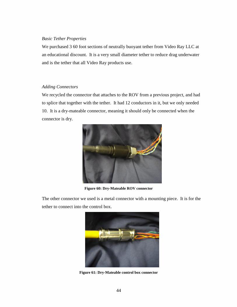
Adding Connectors
We recycled the connector that attaches to the ROV from a previous project, and had
to splice that together with the tether. It had 12 conductors in it, but we only needed
10. It is a dry-mateable connector, meaning it should only be connected when the
connector is dry.
Figure 60: Dry-Mateable ROV connector
The other connector we used is a metal connector with a mounting piece. It is for the
tether to connect into the control box.
Figure 61: Dry-Mateable control box connector
45
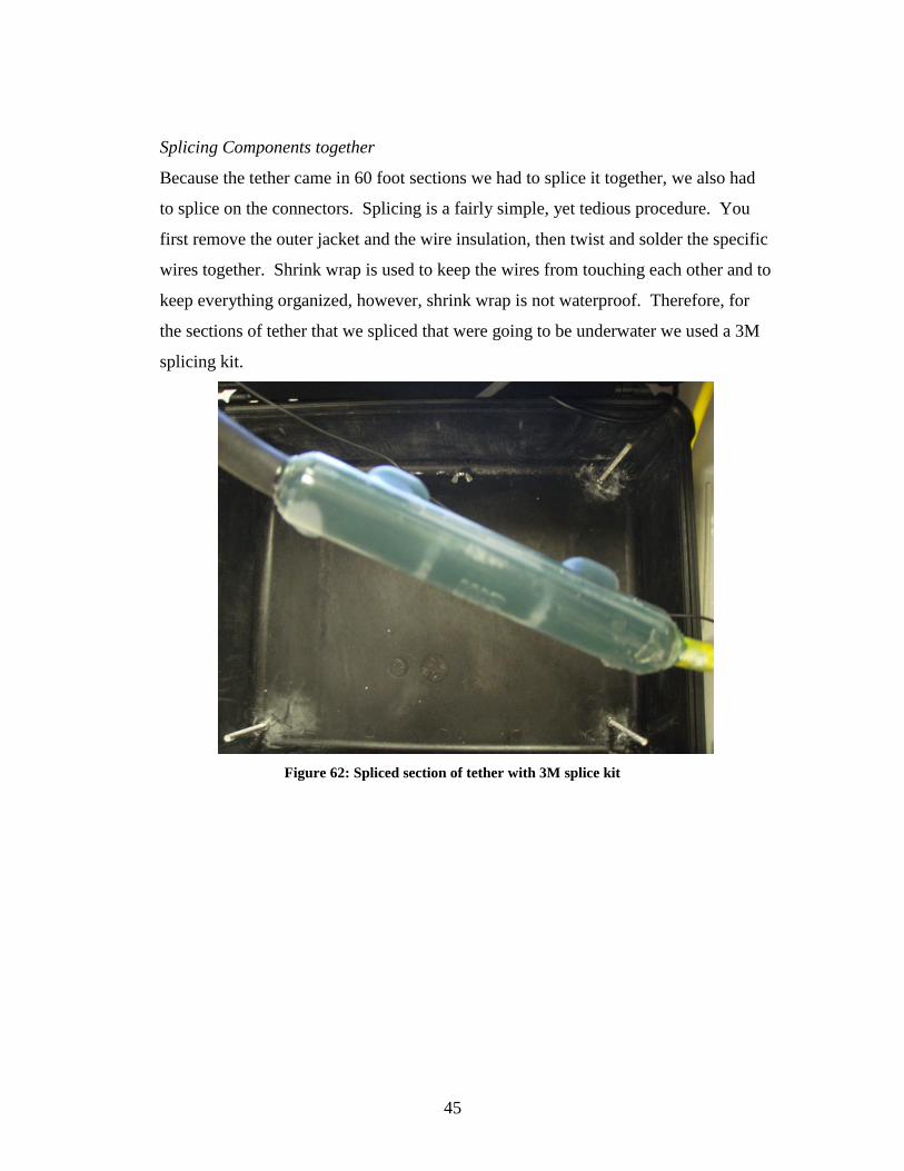
Splicing Components together
Because the tether came in 60 foot sections we had to splice it together, we also had
to splice on the connectors. Splicing is a fairly simple, yet tedious procedure. You
first remove the outer jacket and the wire insulation, then twist and solder the specific
wires together. Shrink wrap is used to keep the wires from touching each other and to
keep everything organized, however, shrink wrap is not waterproof. Therefore, for
the sections of tether that we spliced that were going to be underwater we used a 3M
splicing kit.
Figure 62: Spliced section of tether with 3M splice kit
46
6. Results
Testing Methods
Pool Tests
Test 1: ROV with Dome and Entire Back Plate
The first test was to see if the O-ring seals were water tight. For this, we took the two
end caps and tightened them together with the appropriate nuts and bolts. We placed
them into south gate pool and watched for bubbles. When we saw that there were no
bubbles we moved it into the deep end and left it there for an hour. After we resurfaced
it, we checked for water inside the dome. This test was very successful and there was no
water inside the dome. From this we believed there were no leaks in the O-ring seals.
Test 2: ROV with Dome, Back Plate and Cables and Connectors
Test two was to see if the pressure housing had any leaks with all the tapped holes in the
back-end for all the connectors and in the welds. We placed the whole ROV into the pool
without the electronics, but all the wires were in the connectors. We started again in the
shallow end and worked our way into the deep end looking for bubbles the whole time.
We did not see any bubbles; however, we did notice three drops of water inside the
pressure housing when we brought up our ROV. Because we noticed these drops we
took an air compressor and filled the pressure housing up to 50psi. We put liquid soap
around all the welds and o-ring seals and saw three locations where bubbles occurred.
There were two pin holes in the welding and the back O-ring seal was not sealing
correctly. We discussed the cause of the back O-ring seal and concluded that it’s because
the pressure was pushing out of the pressure housing moving the O-ring out of the groove
instead of the pressure coming from the outside sealing up the O-ring. We brought the
ROV over to the schools machine shop to fix the pin holes.
47
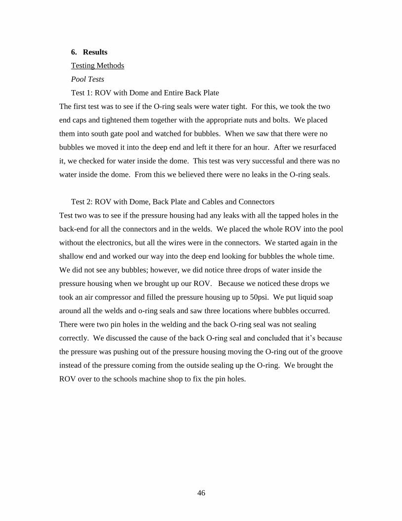
Figure 63: Front view
Figure 64: Top view
Figure 65: Left front view
48
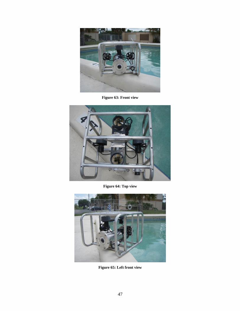
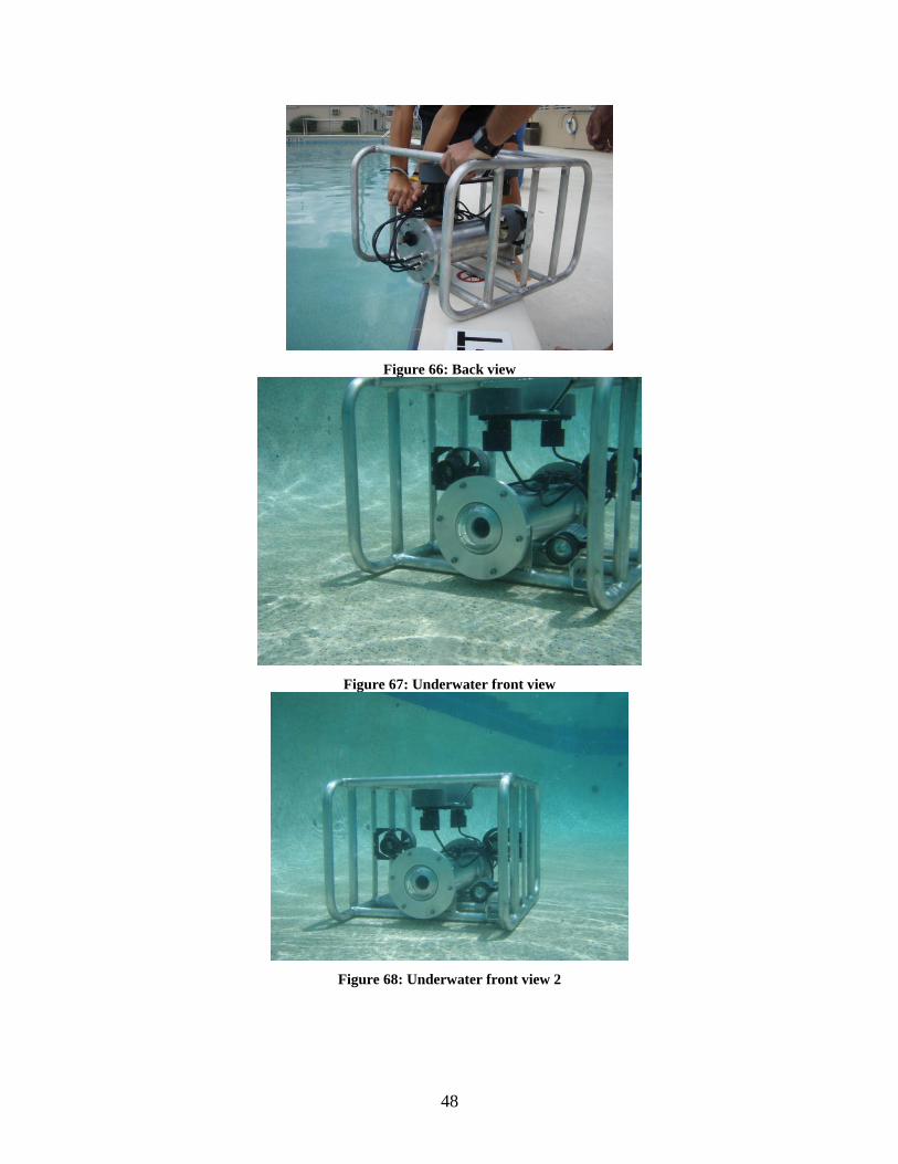
Figure 66: Back view
Figure 67: Underwater front view
Figure 68: Underwater front view 2
49
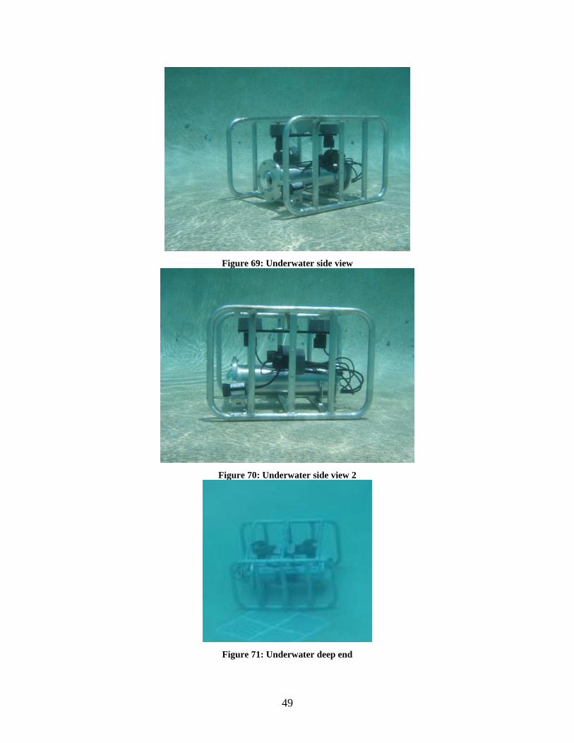
Figure 69: Underwater side view
Figure 70: Underwater side view 2
Figure 71: Underwater deep end
50
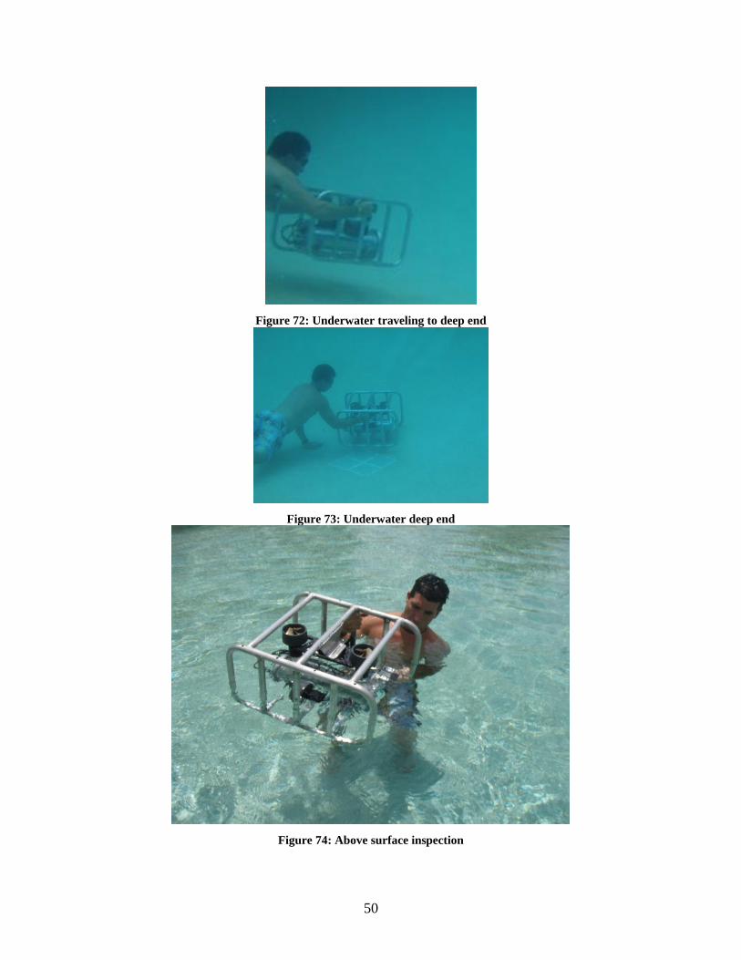
Figure 72: Underwater traveling to deep end
Figure 73: Underwater deep end
Figure 74: Above surface inspection
51
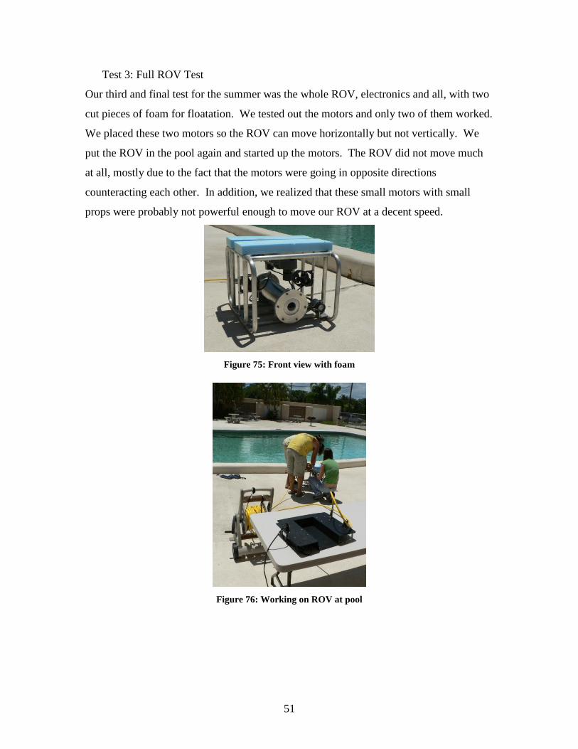
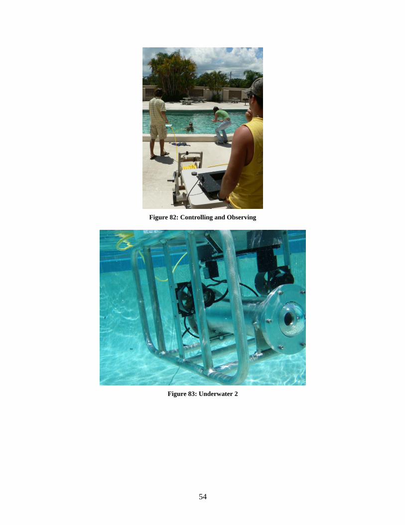
Test 3: Full ROV Test
Our third and final test for the summer was the whole ROV, electronics and all, with two
cut pieces of foam for floatation. We tested out the motors and only two of them worked.
We placed these two motors so the ROV can move horizontally but not vertically. We
put the ROV in the pool again and started up the motors. The ROV did not move much
at all, mostly due to the fact that the motors were going in opposite directions
counteracting each other. In addition, we realized that these small motors with small
props were probably not powerful enough to move our ROV at a decent speed.
Figure 75: Front view with foam
Figure 76: Working on ROV at pool
52
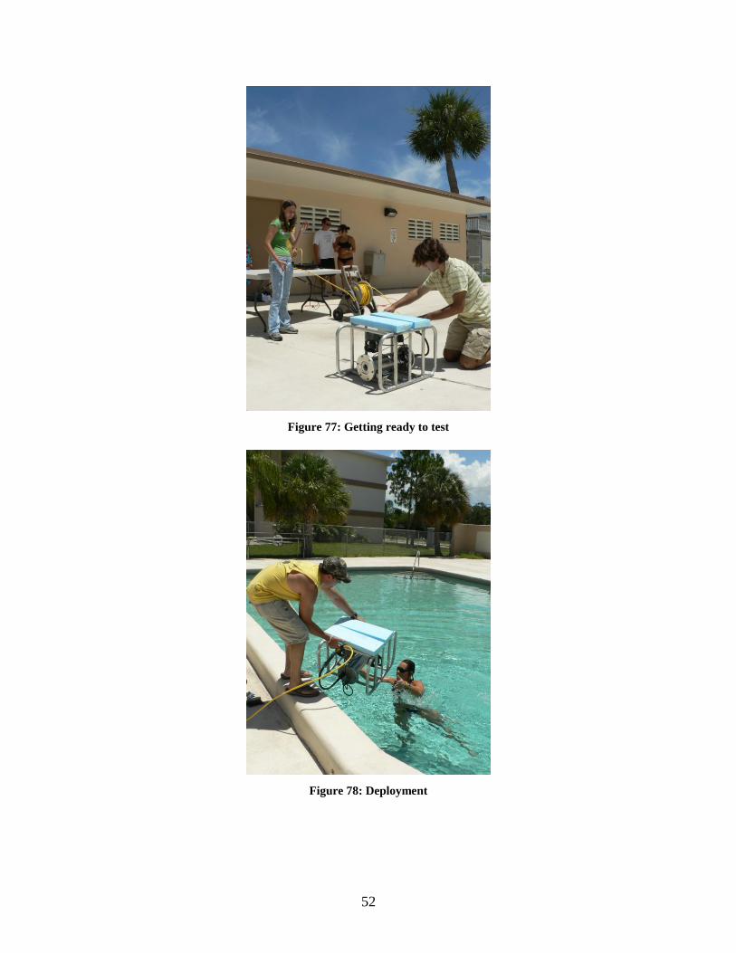
Figure 77: Getting ready to test
Figure 78: Deployment
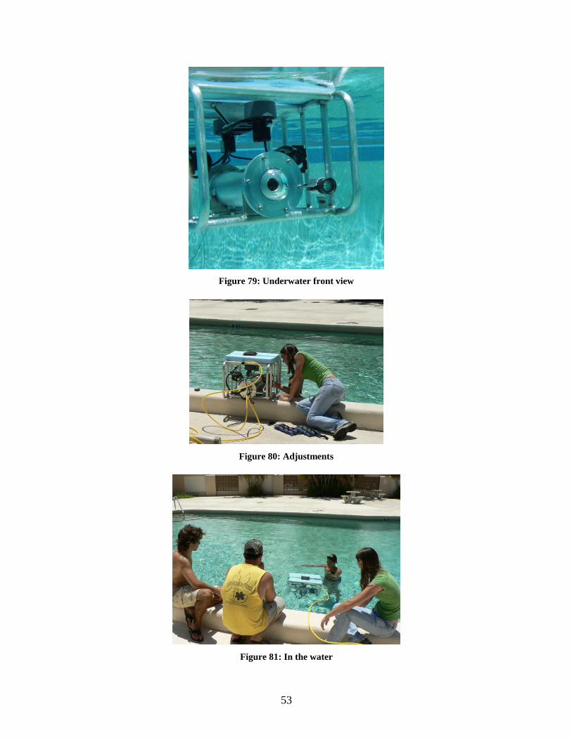
53
Figure 79: Underwater front view
Figure 80: Adjustments
Figure 81: In the water
54
Figure 82: Controlling and Observing
Figure 83: Underwater 2
55
7. Conclusions and Recommendations
From the three tests that we have done we have figured out that much work needs to be
continued on this ROV. During the next two semesters we would like to get our ROV
fully operational and get it ready for the ROV competition for the next summer. To do
this we need to fix the electronics and pot four new motors so they are water proof. In
addition, we need to cut and attach the syntactic foam that we will be using. If we stick
to the motors we are currently using we will have four lateral motors to insure that the
ROV has some momentum to it, otherwise we will put four new motors that have larger
propellers.
There are a few recommendations that the next ROV group should consider. The biggest
recommendation is get the electronics started right away, it takes the longest to do and it
is the hardest part. We also waited too long to get the frame built so by the time we got it
we had to work from 8am to 10pm. Before the frame got here we had to put a lot of
things off until the frame arrived. Another good recommendation would be to try and get
as many sponsors as you can, especially during the spring semester so you have it for the
summer. The two largest factors in this project are time and money. As long as the next
team keeps both of these factors in mind, they should be on the right track.
56
8. Appendices
Appendix A: Project Economics
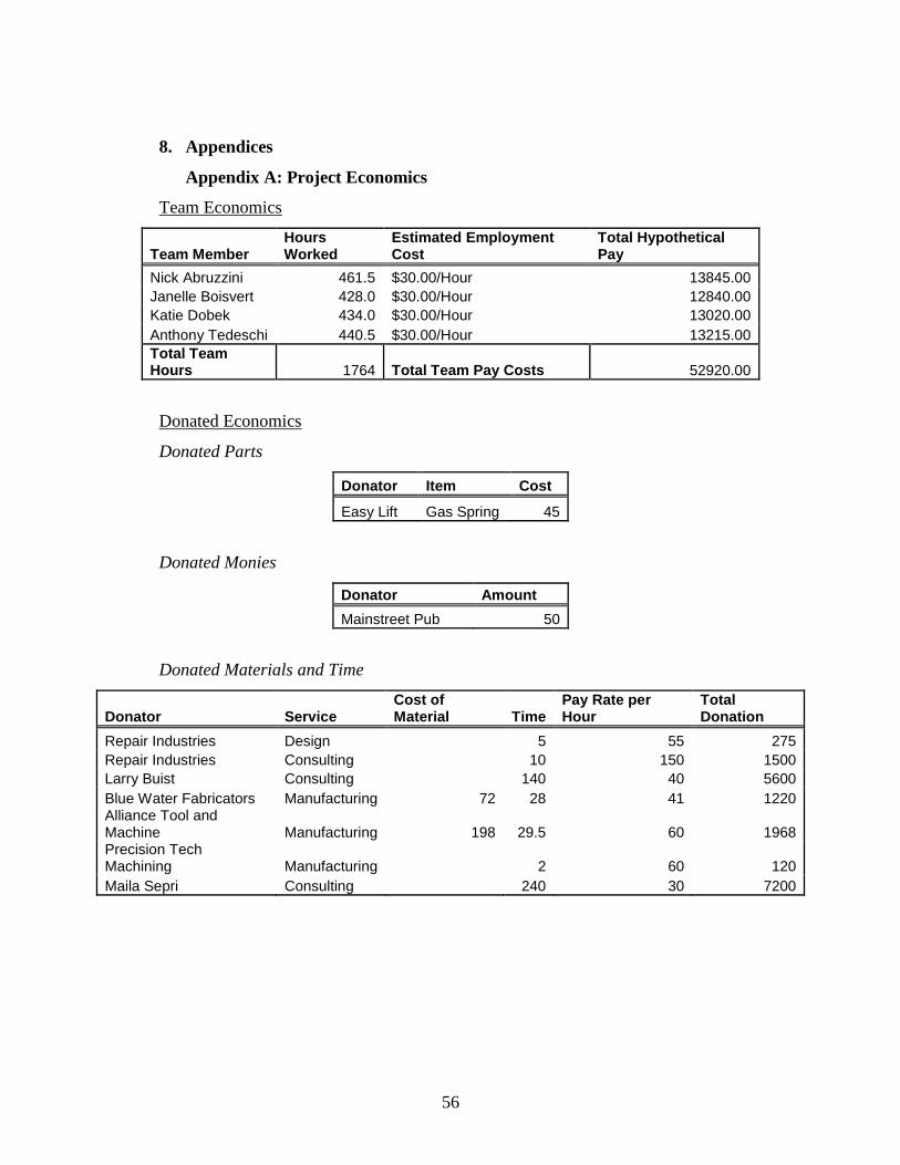
Team Economics
Team Member Hours Worked
Estimated Employment Cost
Total Hypothetical Pay
Nick Abruzzini 461.5 $30.00/Hour 13845.00
Janelle Boisvert 428.0 $30.00/Hour 12840.00
Katie Dobek 434.0 $30.00/Hour 13020.00
Anthony Tedeschi 440.5 $30.00/Hour 13215.00
Total Team Hours 1764 Total Team Pay Costs 52920.00
Donated Economics
Donated Parts
Donator Item Cost
Easy Lift Gas Spring 45
Donated Monies
Donator Amount
Mainstreet Pub 50
Donated Materials and Time
Donator Service Cost of Material Time
Pay Rate per Hour
Total Donation
Repair Industries Design 5 55 275
Repair Industries Consulting 10 150 1500
Larry Buist Consulting 140 40 5600
Blue Water Fabricators Manufacturing 72 28 41 1220 Alliance Tool and Machine Manufacturing 198 29.5 60 1968 Precision Tech Machining Manufacturing 2 60 120
Maila Sepri Consulting 240 30 7200
57
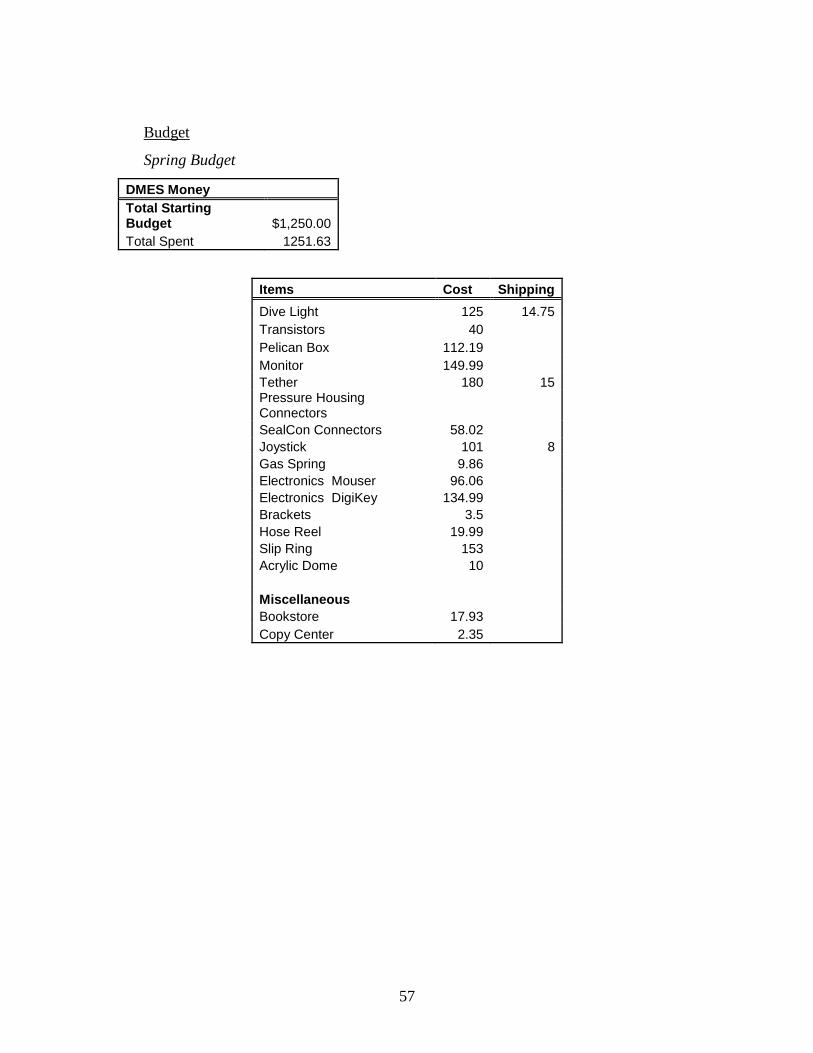
Budget
Spring Budget
DMES Money
Total Starting Budget $1,250.00
Total Spent 1251.63
Items Cost Shipping
Dive Light 125 14.75
Transistors 40
Pelican Box 112.19
Monitor 149.99
Tether 180 15 Pressure Housing Connectors
SealCon Connectors 58.02
Joystick 101 8
Gas Spring 9.86
Electronics Mouser 96.06
Electronics DigiKey 134.99
Brackets 3.5
Hose Reel 19.99
Slip Ring 153
Acrylic Dome 10
Miscellaneous
Bookstore 17.93
Copy Center 2.35
58
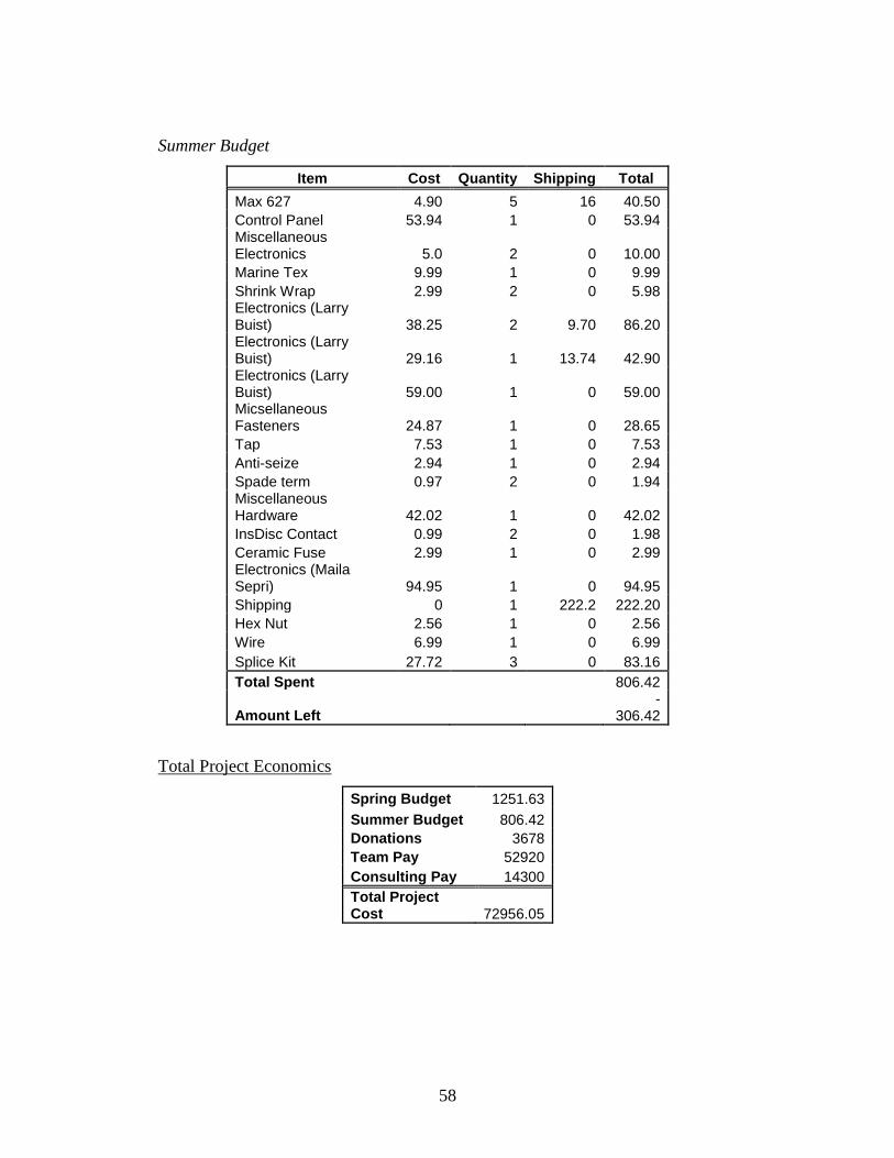
Summer Budget
Item Cost Quantity Shipping Total
Max 627 4.90 5 16 40.50
Control Panel 53.94 1 0 53.94 Miscellaneous Electronics 5.0 2 0 10.00
Marine Tex 9.99 1 0 9.99
Shrink Wrap 2.99 2 0 5.98 Electronics (Larry Buist) 38.25 2 9.70 86.20 Electronics (Larry Buist) 29.16 1 13.74 42.90 Electronics (Larry Buist) 59.00 1 0 59.00 Micsellaneous Fasteners 24.87 1 0 28.65
Tap 7.53 1 0 7.53
Anti-seize 2.94 1 0 2.94
Spade term 0.97 2 0 1.94 Miscellaneous Hardware 42.02 1 0 42.02
InsDisc Contact 0.99 2 0 1.98
Ceramic Fuse 2.99 1 0 2.99 Electronics (Maila Sepri) 94.95 1 0 94.95
Shipping 0 1 222.2 222.20
Hex Nut 2.56 1 0 2.56
Wire 6.99 1 0 6.99
Splice Kit 27.72 3 0 83.16
Total Spent 806.42
Amount Left -
306.42
Total Project Economics
Spring Budget 1251.63
Summer Budget 806.42
Donations 3678
Team Pay 52920
Consulting Pay 14300
Total Project Cost 72956.05
59
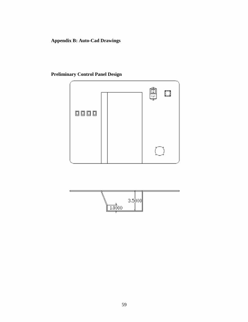
Appendix B: Auto-Cad Drawings
Preliminary Control Panel Design
60
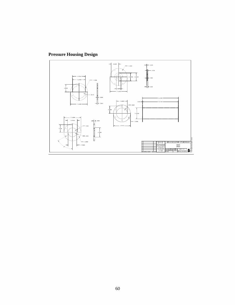
Pressure Housing Design
61
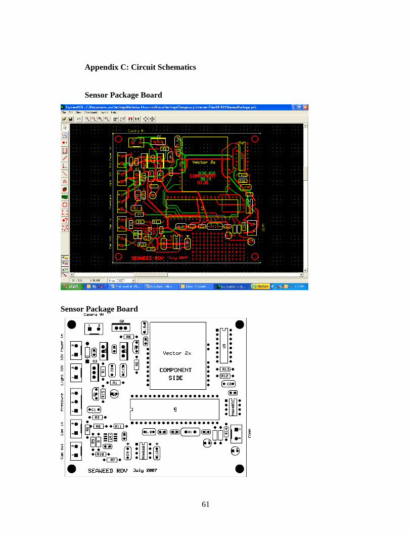
Appendix C: Circuit Schematics
Sensor Package Board
Sensor Package Board
62
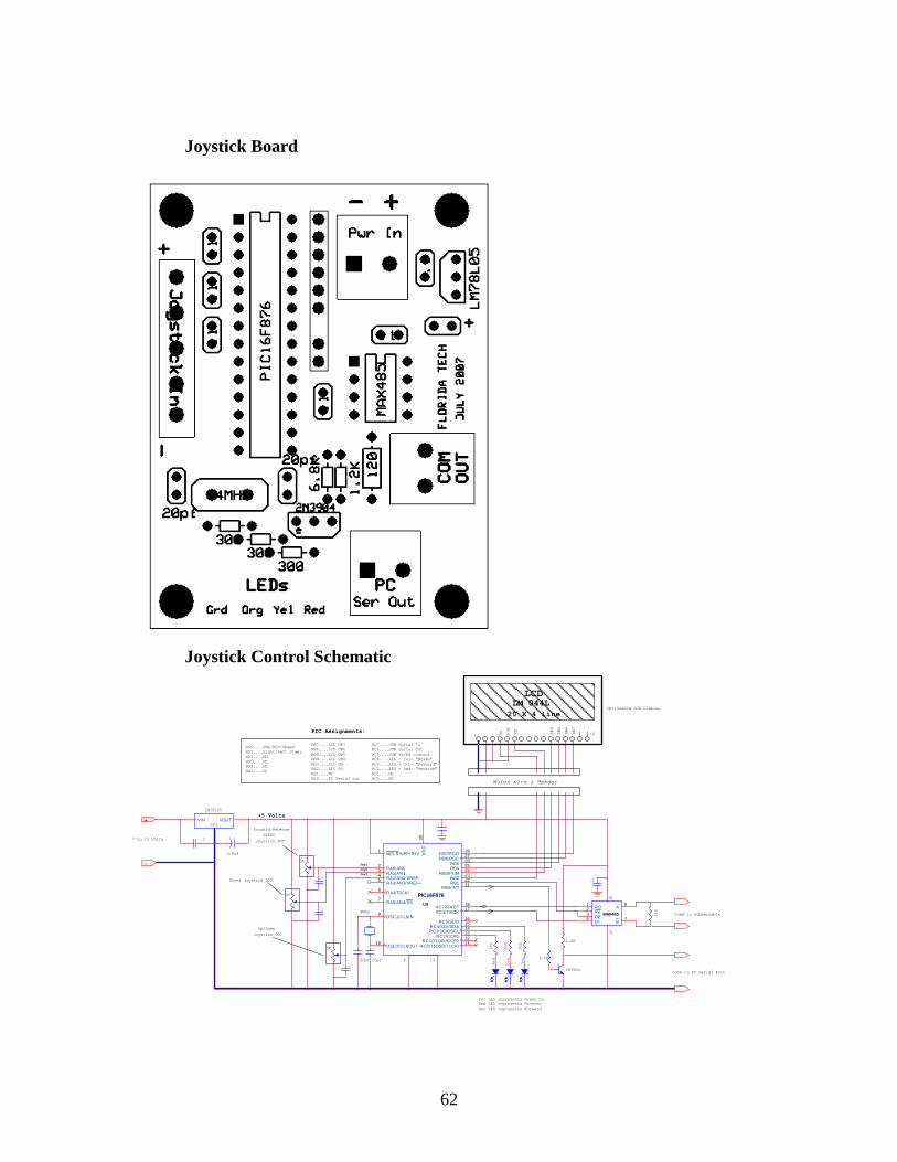
Joystick Board
Joystick Control Schematic
NC
LED - Red- "Reverse"
LED - Grn- "Forward"
LED - Yel- "Brake"
NC
5K
.1
Gen LED represents Forward
Red LED represents Reverse
Yel LED represents Brake On
Grd
8
5
RO1
DI4
RE2
DE3
A6
B7
MAX485
DB6
DB5
DB7
20 X 4 line
NC
LM 044LLCD
RA4....
Molex pins & Header
R/W
EN
RS
161
DB6
NC
RA5....
Forward/Reverse
SPEED
Joystick POT
NC
NC
6.8uf
.1
LM78L05
-
+
7 to 12 Volts
Optionable LCD Display
5K
+5 Volts
198
Joy3
AN0....
PIC Assignments:
AN1....
Up/Down
Joystick POT
AN2....
Joy2
Joy1
AN3....
Right/Left Steer
MCLR/VPP/THV1
RA0/AN02
RA1/AN13
RA2/AN2/VREF-4
RA3/AN3/VREF+5
RA4/T0CKI6
RA5/AN4/SS7
OSC1/CLKIN9
OSC2/CLKOUT10
RC0/T1OSO/T1CKI11RC1/T1OSI/CCP212RC2/CCP113RC3/SCK/SCL14RC4/SDI/SDA15RC5/SDO16
RC6/TX/CK17RC7/RX/DT18
VD
D20
RB0/INT21RB122RB223RB3/PGM24RB425RB526RB6/PGC27RB7/PGD28
U9
PIC16F876
.1
FWD/REV-Speed
20pf 20pf
4MHZ
Steer Joystick POT
6.8K
1.2K
5K
RB2....
RB3....
RB4....
RB5....
RB6....
RB7....
LCD EN
LCD DB4
LCD DB5
LCD DB6
LCD DB7
LCD RS
VIN VOUT
RB1....
RB0....PC Serial out
NC
2N3904
RC7....
.1
.1
RC6....
RC5....
Comm to PC Serial Port
Comm to Submersable
RC4....
300
300
Grn
Red
RC3....
RC2....
Yel
300
.1
120
RC1....
RC0....
SUB TX/RX control
SUB Serial Out
SUB Serial In
63
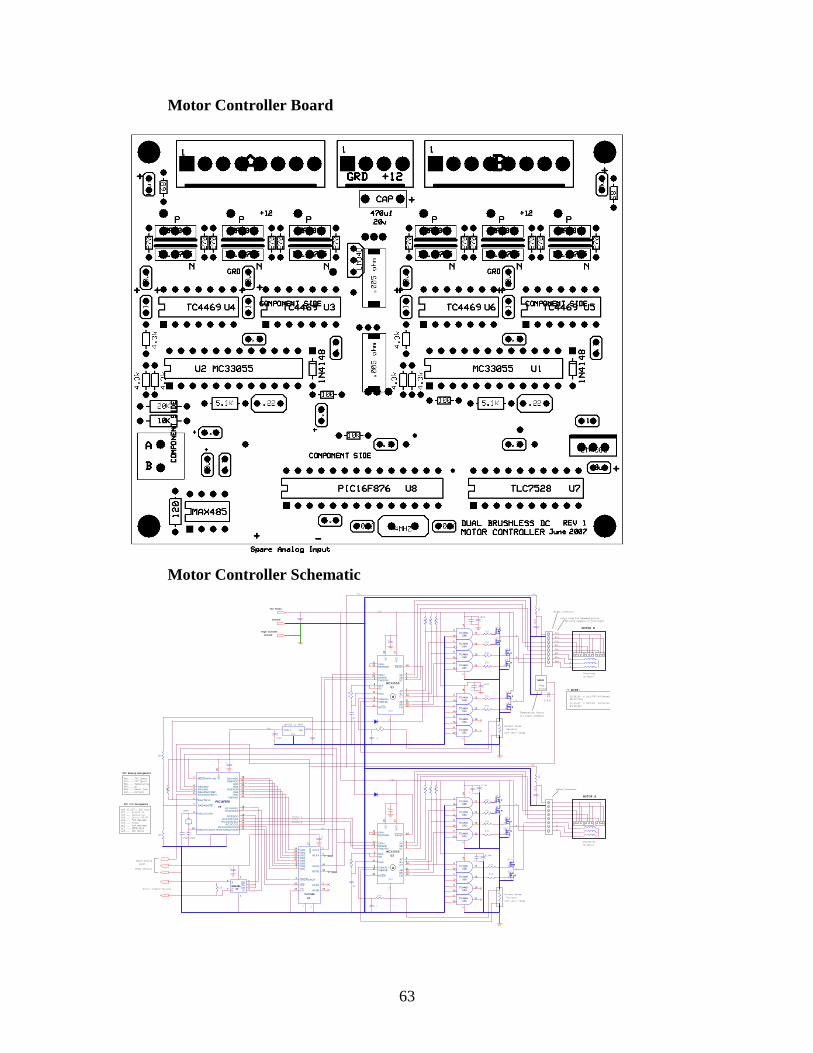
Motor Controller Board
Motor Controller Schematic
Brake
MCLR/VPP/THV1
RA0/AN02
RA1/AN13
RA2/AN2/VREF-4
RA3/AN3/VREF+5
RA4/T0CKI6
RA5/AN4/SS7
OSC1/CLKIN9
OSC2/CLKOUT10
RC0/T1OSO/T1CKI11RC1/T1OSI/CCP212RC2/CCP113RC3/SCK/SCL14RC4/SDI/SDA15RC5/SDO16
RC6/TX/CK17RC7/RX/DT18
VD
D20
RB0/INT21RB122RB223RB3/PGM24RB425RB526RB6/PGC27RB7/PGD28
U8
PIC16F876
OUTA2
OUTB20
DB014
DB113
DB212
DB311
DB410
DB59
DB68
DB77
VD
D17
REFA4
REFB18
DACA/DACB6
WR16
CS15
RFBA3
RFBB19
U7
TLC7528
"B" FWD/REV
8
5
RO1
DI4
RE2
DE3
A6
B7
MAX485
.1
.1
LM7805 or 4805
Grd
8
Temperature Sensor
for board assembly
Temp
Sensor
LM34D
VINVOUT
A
C
B
.1
120
8
* NOTE:
Q2,Q4,Q6 = IRLI3705 N-Channel
Molex Connector
Brushless
DC Motor
A
MOTOR B
C
B
Serial Communications
Molex Connector
Brushless
DC Motor
"A" FWD/REV
+12v
Fwd/Rev A
A
DAC Buss
RA5.....
RA3.....
RA2.....
RA1.....
RA0.....
4.3K
4.7uf
4.3K
4.3K
.1
4.7uf
Red
Blk
Wht
Yel
Brn
Org
Gry
Blu
.1
Color code for SeaWeed motors
.1
D
D
D
D
D
D
S
S
S
S
S
G
G
S
G
G
G
G
MC33055
Temperature
"B" Speed
"A" Speed
N
U2
Battery
P
ERA+11
ERA-12
ISENSE-15
OE7
OSC10
60/12022
AB21
BB20
CB19
AT2
BT1
CT24
FAULT14
REF8
ER/PWM13
VC
18
VC
C17
ISENSE+9
BRAKE23
FWD/RV3
SA4
SB5
SC6
Grd
16
P
N
3
412
14
U4BTC4469
1
213
U4ATC4469
5
611
7
U4CTC4469
8
910
U4DTC4469
3
412
14
U3BTC4469
1
213
U3ATC4469
5
611
7
U3CTC4469
8
910
U3DTC4469
Q11
Q10
Q9
Q7
Q12
Q8
Q1,Q3,Q5 = IRF5305 P-Channel
Fwd/Rev B
5
P
N
C
PIC Analog Assigments
270
270
270
270
270
270
B
6
MOTOR A
7
1
2
3
Current Sense
Resistor
4
Q8,Q10,Q12
(Temp sensor)
____
PIC I/O Assigments
Serial RX/TX
A
4.3K
4.3K
10uf
10uf
4.3K
.1
.1
.1
D
D
D
D
D
D
S
S
S
S
S
G
GS
G
G
G
MC33055
G
N
U1
P
ERA+11
ERA-12
ISENSE-15
OE7
OSC10
60/12022
AB21
BB20
CB19
AT2
BT1
CT24
FAULT14
REF8
ER/PWM13
VC
18
VC
C17
ISENSE+9
BRAKE23
FWD/RV3
SA4
SB5
SC6
Grd
16
N
P3
412
14
U6BTC4469
1
213
U6ATC4469
5
611
7
U6CTC4469
8
910
U6DTC4469
3
412
14
U5BTC4469
1
213
U5ATC4469
5
611
7
U5CTC4469
8
910
U5DTC4469
Q5
Q1
Q2
Q4
Q3
Q6
U9
5
RC4....
RC5....
RC6....
RC7....
RB0 TO RB7....
N
P
C
270
270
270
270
DAC Write
DACA/DACB
B
270
270
"B" Speed
"A" Speed
Q7,Q9,Q11
Brake
6
Ground
High Current
Ground
+5v
+5v
+5v
7
+12 Volts
6.8uf
RC3....
+5v
+12v
+12v
51
1
(Blu/Gry swapped on prototype)
+5v
RC2....
.005 ohm = 20amp
.005 ohm = 20amp
5.1K
.22
.22
.1
10uf
5.1K
RC1....
2
10K
20K
20pf 20pf
4MHZ
68
68
10uf
10uf
10K
3
B
A
RA4.....
RC0....
100
.1
.1
100
4
NC
Current Sense
Resistor
Spare Analog
Input
Fault Ind.
Serial Out
Serial In

64
Appendix D: References
1. Hornet II report
2. www.isope.org/publications/journals/ijope-11-4/ijope-11-4-p282-abst-WK-56-
Buckham-2.pdf
3. http://oceanexplorer.noaa.gov/technology/subs/rov/rov.html
4. http://www.rov.org/educational/pages/Ballast.html
5. http://www.sharkmarine.com/Stealth2Article.htm
6. http://www.videoray.com/Products/scout.php
7. http://www.seabotix.com/