the role of cool thermal energy storage (ctes) in the
TRANSCRIPT
at SciVerse ScienceDirect
Energy 48 (2012) 108e117
Contents lists available
Energy
journal homepage: www.elsevier .com/locate/energy
The role of cool thermal energy storage (CTES) in the integration of renewableenergy sources (RES) and peak load reduction
Marko Ban*, Goran Kraja�ci�c, Marino Grozdek, Tonko �Curko, Neven Dui�cUniversity of Zagreb, Faculty of Mechanical Engineering and Naval Architecture, Ivana Lu�ci�ca 5, 10000 Zagreb, Croatia
a r t i c l e i n f o
Article history:Received 1 November 2011Received in revised form25 June 2012Accepted 26 June 2012Available online 9 August 2012
Keywords:BuildingsCool thermal energy storageRenewable energy sourcesModelling
* Corresponding author. Tel.: þ385 1 6168 494; faxE-mail address: [email protected] (M. Ban).
0360-5442/$ e see front matter � 2012 Elsevier Ltd.http://dx.doi.org/10.1016/j.energy.2012.06.070
a b s t r a c t
The building sector is one of the largest energy consumers. Even though cooling needs do not contributea large share to the overall energy demand in temperate climates, recent trends show a tendency of largegrowth. This growth is related to two main drivers: cheap and affordable air-conditioning units that haveoverrun the market and the more frequent occurrence of hot and extremely hot weather conditions. Incombination with inadequate insulation and sealing in most old buildings, both drivers contributed tonew cooling installations that are significantly increasing electricity demand and peak load, even at thenational level. Consequently, the use of fossil fuels in power plants and electricity import has increased.The development of sustainable buildings and the use of renewable energy sources (RES) seem to bepromising solutions. However, the problem of the integration of RES in the current energy system isrelated to their intermittent nature and uncontrollable occurrence.
Cool Thermal Energy Storage (CTES) may play an important role in the management of peak loads andsolve the intermittency problem of RES, especially when cooling storage is integrated into district coolingsystems. A simple mathematical model of a system with integrated RES and CTES has been developed.Hourly system analyses have been conducted for one building, a group of buildings connected to thedistrict cooling system and a region represented by a mixture of different demands for cool thermalenergy. This paper also includes the results for the overall energy efficiency, cost effectiveness andenvironmental impact of the systems analysed.
� 2012 Elsevier Ltd. All rights reserved.
1. Introduction
The energy use in residential, public and commercial buildingsrepresents a major share of the overall final energy consumptionand CO2 emissions of the EU, totalling approximately 40% [1]. Thus,the potential for cost-effective energy savings in the building sectoris substantial and estimated to be as high as 28% of the primaryenergy demand by 2020 [2]. Effective management of Cool ThermalLoad in buildings by Cool Thermal Energy Storage (CTES) willgarner more attention, due to the new EU Directive on the energyperformance of buildings [3]. The application of CTES could lead todefinite energy savings, but it also has the potential for the inte-gration of renewable energy sources (RES) and could make zeroenergy buildings more achievable.
Market research published in 2005 by CENERG shows that only27% of the European tertiary sector (schools, hospitals, offices,hotels, restaurants, shops) and 5% of the residential sector are
: þ385 1 6156 940.
All rights reserved.
equipped with room air conditioners. It is expected that in the nextdecade, the EU market will reach the saturation rate of 60% for theservice sector and 40% for the residential sector, showing a fourfoldincrease of the cooling market between 2000 and 2018. Thisincrease corresponds to a cooling demand of 500 TW hc with anelectricity demand of 200 TW h for the countries of the EU [4].Cooling appliances had a 10% share of tertiary electricityconsumption in EU27 in 2004 [2]. For Croatia, Grozdek [4] esti-mated the total potential of the cooling demand to be 5 TWh c withan electricity demand of 1.8 TW h while Puk�sec [5] describedmethodology for calculation of energy consumption of a house-holds sector which also includes needs for space cooling andrelated electricity consumption.
Application of CTES in buildings and energy systems has manyadvantages [6]. If properly designed, CTES can lower the requiredchiller capacity and related investment and operation costs, aspresented by Andrepont [7] and Grozdek [4]. Scheduling chillers tofill the CTES during the night allows them to operate more effi-ciently because night temperatures are lower than those during theday, and electricity cost is also possibly lower. Deferred loads alsodecrease the daily peaks [8,9]. Beside buildings, CTES are efficiently

M. Ban et al. / Energy 48 (2012) 108e117 109
applied to various industrial processes and district cooling systems.Moreover, it represents effective storage for RES integration (asseen in Lund et al. [10]), which a new subject that requires moreattention from researchers.
The paper is organised into four major sections: Motivation andbackground, Methodology andmodel, Case studies and Results and,finally, the Conclusion.
2. Motivation and background
In this section, the main incentives for conducting research arestated with a short description of CTES technology and operationprinciples.
2.1. Directive 2010/31/EU
One of the major drivers that could revolutionise the construc-tion of new buildings and drastically change the primary energyconsumption of the building sector is the new Directive 2010/31/EUof the European Parliament and the Council on the energy perfor-mance of buildings fromMay 19th 2010 [3]. The important Article 9prescribes that Member States shall ensure that all new buildingsare near zero-energy by December 31st 2020 and that afterDecember 31st 2018, new buildings, occupied and owned by publicauthorities, are also near zero-energy. In addition to this article, theDirective prescribes the requirements on the building envelope,ventilation heating and cooling. Theminimum energy performancerequirements that are not cost-effective over the estimatedeconomic lifecycle are not required and thus do not need to beprescribed. When setting requirements, member states maydifferentiate between new and existing buildings and differentcategories of buildings.
Before starting the construction of new buildings in all memberstates, it will be necessary to assess the technical, environmentaland economic feasibility of high-efficiency alternative systems,such as the following:
a) decentralised energy supply systems based on energy fromrenewable sources;
b) cogeneration;
Fig. 1. Number of imported air conditioning units in Croatia
c) district or block heating or cooling, particularly where it isbased entirely or partially on energy from renewable sources;
d) heat pumps.
The same directive describes ‘district heating’ or ‘district cool-ing’ as the distribution of thermal energy in the form of steam, hotwater or chilled liquids, from a central source of productionthrough a network to multiple buildings or sites, for the use ofspace or process heating or cooling.
For further development of CTES, it is important for the analysisof alternative systems to be carried out for individual buildings,groups of similar buildings, or common typologies of buildings inthe same area. As far as collective heating and cooling systems areconcerned, the analysis may be carried out for all buildings con-nected to the system in the same area.
2.2. Intermittency, energy independency and energy storage
Even with new buildings having minimised energy consump-tion, there will be certain commodities that will require a specificform (amount) of energy, making the energy neutrality of buildingsachievable only through intensive integration of RES. Problems thatoccur in systems with high RES penetration are mostly related tothe intermittent and uncontrollable nature of RES. Integrationproblems have been tackled by many authors, and they mostlypropose solutions in the form of various types of energy storage, asshown, for instance, by Kraja�ci�c et al. in Refs. [11,12]. Most of theseproblems attempt to solve the integration problems from the sideof the energy system, and it is interesting that, until now, CTES didnot receive proper attention as storage for RES integration on thelocal level and also for regional or even national energy systems.Most studies related to CTES propose it as a solution for costreduction and peak load management, emphasising the relatedfinancial and environmental benefits. In addition to these provenbenefits, CTES will certainly help to reduce the variability ofprimary sources and also to reach a certain level of energy inde-pendency, thus increasing security for the energy supply. As it hasalso been highlighted, energy storage is important pillar of a postcarbon society (shown by Kraja�ci�c et al. in Ref. [13]) and a crucialstep for the achievement of 100% RES systems [14].
(Source: Croatian Bureau of Statistics, Foreign office).

Table 2Increase in the average temperatures in August for the most populated cities inCroatia in the period 2007e2010 [17].
City Population C� aboveaveragetemperature.August 2007.
C� aboveaveragetemperature.August 2008.
C� aboveaveragetemperature.August 2009.
C� aboveaverageemperature.August 2010.
Zagreb 779,145 1.4 1.9 3 1.1Split 188,694 1.6 2.5 2.6 1.5Rijeka 144,043 1.3 2.4 3.3 0.9Osijek 114,616 1.9 1.5 2.6 1.4
Table 1Increase in the average temperatures for the most populated cities in Croatia in theperiod 2007e2010 [17].
City Population C� aboveaveragetemperature.year 2007.
C� aboveaveragetemperatureyear 2008.
C� aboveaveragetemperatureyear 2009.
C� aboveaveragetemperature.Year 2010.
Zagreb 779,145 2.4 1.9 1.9 1.9Split 188,694 2.3 2.0 1.3 1.4Rijeka 144,043 2.0 2.1 1.9 1.5Osijek 114,616 2.5 1.4 1.5 1.5
M. Ban et al. / Energy 48 (2012) 108e117110
2.3. Temperatures and power load
In Croatia, there are approximately 2 million apartments, withmore than 45% built before 1970, and the rate of housing stockincreases by 1% per year [15]. The old buildings do not have properwall insulation because they were built before any energy policieswere prescribed for the building sector. The direct consequencesare high winter loads in power systems, which can be directlylinked to low temperatures and the use of electricity for heatingpurposes. Current analyses show a similar behaviour of powersystems during the summer, which is related to the installation ofcheap and affordable air-conditioning units that overran themarket (almost one million units in the last ten years e Fig. 1) andmore frequent hot and extremely hot weather conditions.Combinedwith inadequate insulation and sealing inmost of the oldbuildings, there has been a significant increase of electricitydemand and peak loads, even on the national level.
In the last decade, according to the Croatian Hydro Meteoro-logical Institute, the average summer air temperatures in the fourmost populated cities (housing approximately one third of theCroatian population) have increased by 2.4 �C above the averagetemperatures measured in the period of 1961e1991, as displayed inTable 1.
Comparing the temperatures shown in Table 1 to the meanvalues of the national system load presented in Fig. 2, it is clear thaton average, the warmest summer was in 2007 while on the otherhand, it had the lowest mean load in the power system. Informationon the increased power load due to the temperature increasecannot be drawn through this comparison. The better conclusioncan be drawn from Table 2 and Fig. 3, where the increase of theaverage temperatures in August is shown together with the loadincrease for different years. Even with the significant influence ofeconomic recession, the loads in 2009 were the highest, which isa direct consequence of the highest increase of temperatures at anaverage of 2.875 �C in the four major cities.
Fig. 2. Mean hourly load of the Croatian power system in MW for the periodJuneeSeptember and �0.95 Conf. Interval [16].
Fig. 4 illustrates the link between the temperature and loadincrease while the statistical correlations between the two aregiven in Table 3. As the temperature rises, the correlations increase,which could also lead to the conclusion that in this case, the loadprofile better traces the temperature. To calculate the detailedinfluence of the temperature on the summer load profile of anentire power system and on the increase in peak power require-ments, a more detailed analysis of different influence parameters isneeded (cooling space and cooling saturation rates; economyrelated activities, e.g., tourism; average size and capacity of coolingunits; etc.). However, this type of analysis is out of the scope of thisarticle.
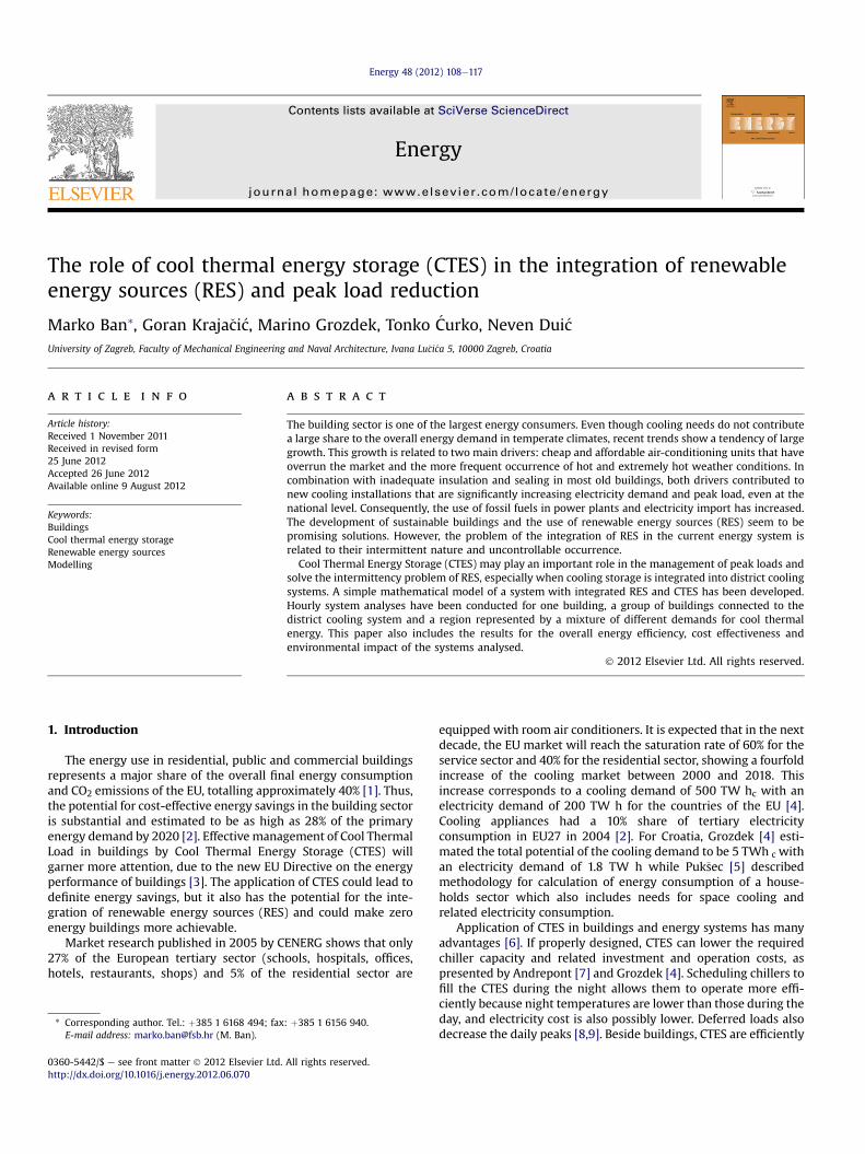
A summer load in the Croatian power system, displayed in Fig. 5,has two daily peak periods, the first one from 10 to 16 h and thesecond one from 20 to 24 h. The important fact is that thesesummer periods have more similar peak values than those duringthe winter loads, when the night peak component is approximately200 MW higher than the daily one, as shown in Fig. 6.
2.4. CTES application, operation and technology
As previously mentioned, CTES has been effectively applied inindustrial, residential and commercial buildings and district cool-ing systems (as shown by Gorzdek [4], Dincer et al. [19e21]). Thesizing of CTES and ancillary equipment depends more on economicparameters than on the technical requirements. Similarly, opera-tion strategies will also be assessed more from the economic sidethan the technical side.
There are three basic storage-sizing and operation strategies:full storage, load-levelling partial storage and demand-limitingpartial storage. For the purpose of this paper, additional operationstrategies for the maximisation of RES integration by CTES have
Fig. 3. Mean hourly load of the Croatian power system in MW for August (07e24 h)and �0.95 Conf. Interval [16].

Fig. 4. Mean hourly temperatures and Croatian power load in the period 17the30th August.
M. Ban et al. / Energy 48 (2012) 108e117 111
been developed and tested, as described in the next paragraph.CTES is primarily applied for the reduction of the operating costs ofthe system, which can be as high as 70%. The payback period forusing CTES is usually from 2 to 6 years, but for a more accurateprediction, several building specific pieces of information arerequired: the hour-by-hour power usage, the performance of theproposed cool storage system, and the tariff model of the localelectrical utility, as presented by Dincer et al. in Ref. [19].
In this study, three operation strategies have been analysed. Thefirst operation strategy of CTES that has been calculated was a nightoperation, where the filling of CTES was allowed only during theperiod of the night tariff, 22 he08 h. The limitation on thecompressor power during daily operation was not set because itwas used to partly satisfy the load after the discharge of CTES. Thesecond strategy included RES with only PV electricity used forfilling the storage and operation of compressors and thus enablingzero energy buildings. For this strategy, it was necessary to cover allavailable surfaces with photovoltaic modules. The third operationstrategy included charging CTES only during the low tariff periodand discharge during the daily peak period, which has been definedas a percentage of the maximal load in each day. In this case, CTESwas discharged only when the load was above a certain limit, asdefined in Table 4.
Additionally, even traditionally designed chiller plants withsmall efficiency improvements can multiply to create significantsavings in district cooling plants. These benefits are emphasised ina larger framework, where they become more obvious and valu-able. For example, district cooling is being embraced on a largescale by the United Arab Emirates to accommodate its tremendousgrowth, with an estimated 75% of the energy in Dubai used for
Table 3Correlations of mean hourly temperatures measured in Split (presented by Karad�zaet al [18].) and Croatian hourly power load [16] for the periodMayeSeptember 2008.
Variable Means Std. dev. Correlations
May load [MW] 1810.882 316.6377 0.467052May temp. [�C] 20.397 3.8786June load [MW] 1907.903 348.1751 0.529325June temp. [�C] 24.075 4.6856July load [MW] 2029.028 350.5198 0.547777July temp. [�C] 26.676 3.7781August load [MW] 1967.243 346.2948 0.608089August temp. [�C] 27.129 3.5652September load [MW] 1953.365 347.1538 0.302078September temp. [�C] 20.875 5.7328
cooling. Rather than utilising individual cooling systems in eachbuilding, with district cooling, a reduction of 40% of the energy usedis expected by the Dubai planners (see Hanson et al. [22]).
District cooling (and heating, which is out of the scope of thispaper) is commonly defined as the distribution of heat transfermedia from a central energy production source to meet the diversethermal energy needs of residential, commercial, and industrialusers. These needs include space cooling (or heating) systems formaintaining primarily human comfort, and manufacturing-plantprocess cooling (or heating) system requirements, but, despite itsbenefits, many of the systems installed around the world do notprovide both district heating and cooling. For example, in Europe,most district systems provide only heating because of the prevail-ing moderate summer temperatures. North America, however,which has higher extreme summer temperatures in the southernparts (approximately 30e40 �C over extended periods), isbecoming a leading region with district cooling being more wide-spread (Dincer et al. [23]).
The cooling for data centres will also need to be considered bydistrict cooling systems, especially in zones with significant publicand business service sectors. As shown in Ref. [2], it was envisagedthat without proper action, the electricity demand of data centresin 2010 will reach nearly 70 TW h. It was also estimated thatapproximately half of the electricity consumption of a data centre isdue to server infrastructure (for cooling and lighting [2]).
Fig. 5. Plot of the hourly mean load in August 2008 for a 24 h period [16].
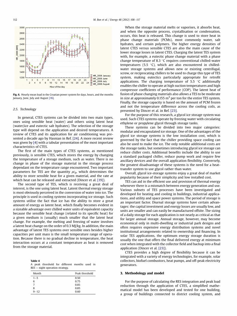
Fig. 6. Hourly mean load in the Croatian power system for days, hours, and the monthsJanuary, June, July and August [16].
M. Ban et al. / Energy 48 (2012) 108e117112
2.5. Technology
In general, CTES systems can be divided into two main types,ones using sensible heat (water) and others using latent heat(water/ice and eutectic salt hydrates). The selection of the storagetype will depend on the application and desired temperatures. Areview of CTES and its application for air conditioning was pre-sented a decade ago by Hasnian in Ref. [24]. A more recent reviewwas given by [4] with a tabular presentation of the most importantcharacteristics of CTES.
The first of the main types of CTES systems, as mentionedpreviously, is sensible CTES, which stores the energy by changingthe temperature of a storage medium, such as water. There is nochange in phase of the storage material in the storage processdependant on the temperature range encountered. Two importantparameters for TES are the quantity rcp, which determines theability to store sensible heat for a given material, and the rate atwhich heat can be released and extracted (Dincer et al. [19]).
The second type of TES, which is receiving a great deal ofinterest, is the one using latent heat. Latent thermal energy storageis most obviously perceived in the conversion of water into ice. Theprinciple is used in cooling systems incorporating ice storage. Suchsystems utilise the fact that ice has the ability to store a greatamount of energy as latent heat, which finally becomes evident ina sizeable advantage over chilled water units of equivalent capacitybecause the sensible heat change (related to its specific heat) fora given medium is (usually) much smaller that the latent heatchange. For example, the melting and freezing of water involvesa latent heat change on the order of 0.3 MJ/kg. In addition, the mainadvantage of latent TES systems over sensible ones besides highercapacities per unit mass is the small temperature range of opera-tion. Because there is no gradual decline in temperature, the heatinteraction occurs at a constant temperature as heat is removedfrom the storage material.
Table 4A peak threshold for different months used inRES þ night operation strategy.
Month Peak threshold
1e5 0.506 0.757 0.858 0.859e12 0.60
When the storage material melts or vaporises, it absorbs heat,and when the opposite process, crystallisation or condensation,occurs, this heat is released. This change is used to store heat inphase change materials (PCMs), most commonly water, salthydrates, and certain polymers. The higher energy densities oflatent CTES versus sensible CTES are also the main cause of thelower storage losses in latent CTES. Charging the latent TES systemwith, for example, a eutectic phase change material with a phasechange temperature of 8.3 �C requires conventional chilled-watertemperatures (5.5 �C), which are also encountered in chilled-water storage systems and allows new or existing centrifugal,screw, or reciprocating chillers to be used to charge this type of TESsystem, making eutectics particularly appropriate for retrofitapplications. The charging temperature of 5.5 �C additionallyenables the chiller to operate at high suction temperatures and highcompressor coefficients of performance (COP). The latent heat offusion of phase changingmaterials also allows a TES to bemoderatein size at approximately 0.155 m3 per ton for the entire TES system.Finally, the storage capacity is based on the amount of PCM frozenand not the temperature difference across the cooling coils, aspresented by Dincer et al. in Ref. [23].
For the purpose of this research, a glycol ice storage systemwasused. Such CTES systems operate by freezing water with circulatingethylene or propylene glycol through storage tanks.
These systems can be divided into two major categories:modular and encapsulated ice storage. One of the advantages of theglycol ice storage systems is the low installation cost, which isgoverned by the fact that the chiller providing space cooling canalso be used to make the ice. The only notable additional costs arethe storage tanks, but sometimes introducing glycol ice storage canreduce chiller costs. Additional benefits include the ability to usea standard packaged chiller, reduce pump work and require fewancillary devices and the overall application flexibility. Conversely,the greatest disadvantage of these systems is the need for a heat-transfer system to use glycol rather than water.
Overall, glycol ice-storage systems enjoy a great deal of marketpopularity because of their simplicity and low installed cost.
TES can aid in the efficient use and provision of thermal energywhenever there is a mismatch between energy generation and use.Various subsets of TES processes have been investigated anddeveloped for heating and cooling in buildings, industrial applica-tions, and utility and space power systems. The period of storage isan important factor. Diurnal storage systems have certain advan-tages: the capital investment and energy losses are usually low, andunits are smaller and can easily be manufactured offsite. The sizingof a daily storage for each application is not nearly as critical as thatfor larger annual storage. Annual storage, however, may becomeeconomical only in multi-dwelling or industrial park designs andoften requires expensive energy distribution systems and novelinstitutional arrangements related to ownership and financing. Insolar TES applications, the optimum energy storage duration isusually the one that offers the final delivered energy at minimumcost when integrated with the collector field and backup into a finalapplication (Dincer et al. [23]).
CTES provides a high degree of flexibility because it can beintegrated with a variety of energy technologies, for example, solarcollectors, biofuel combustors, heat pumps, and off-peak electricitygenerators.
3. Methodology and model
For the purpose of calculating the RES integration and peak loadreduction through the application of CTES, a simplified mathe-matical model has been developed and tested for one building,a group of buildings connected to district cooling system, and

Fig. 7. York screw compressor power and COP for different inlet water and outlet glycol temperatures.
M. Ban et al. / Energy 48 (2012) 108e117 113
a region represented by a mixture of different demands for coolthermal energy. The solar and wind modules from the H2RES pro-gramme have been used for the calculation of the production by PVmodules and wind turbines. H2RES is explained by Kraja�ci�c et al.[25] and Lund et al. [26]. Finally, the evaluation of different solu-tions has been conducted for the overall energy efficiency, costeffectiveness and environmental impact of the systems analysed.
The CTES system used in this paper is modelled according to Ref.[20] (CRYOGEL Ice Ball Thermal Storage), including chillers, tankswith encapsulated water/ice and a cooling load. The chillers arerepresented by the maximum and minimum electric power loadper compressor, the number of units of the same power and theirCOPs. Tanks are represented by their count, the maximum storagecapacity for the same group of tanks, and the maximum andminimum input and output loads per hour. As shown by Bédé-carrats et al. in Refs. [27] and [28], one can make an approximationwhere the stored energy is linearly dependant during an hour ofthe charge/discharge process above 10% and up to 90% of the totalinstalled capacity with a constant coolant temperature and flowrate. The thermal load is calculated for each case study anddescribed in more detail in the following chapter.
Three operation strategies have been applied in the case studiesdescribed in the previous section. The first strategy is regarded asthe referent strategy, where the storage was filled only during the
Fig. 8. Buildings used for simulat
night or low tariff period, in which chillers were used partly forcovering the load and filling the storage. Second, there was the RESstrategy, where the storage was filled only by available RES elec-tricity, and finally, there was the RES þ night strategy as a combi-nation of the first two.
Grozdek concluded in Ref. [4] that it is impossible to finda rather simple, fast, yet sufficiently accurate method to describethe performance of CTES systems over time, which is also sup-ported by the mathematical model developed by Bédécarrats et al.[28], mostly due to the high process complexity and nonuniformitythroughout the CTES system (the situation can differ drasticallybetween pipe segments, pipes and modules in the same silo). Acomplex computer model is thus needed (also shown by modellingexamples by Wei et al. in Ref. [29] or Assis et al. in Ref. [30]). Thesimulation results clearly show that to propose an adequate systemdesign, no simple engineeringmethods or rule-of-thumb principlescould be utilised. As indicated, the results of an initial sizingprocedure are far from the “real” behaviour of an ice bank system.
The COP of the chillier (compressor) in the secondary coolingloop is dependent on the desired outlet temperature of the glycoland inlet temperature of the cooling water. The COP increases asthe inlet water temperature decreases and outlet glycol tempera-ture increases, as presented in Fig. 7. Thus, there is another reasonwhy detailed models of CTES systems are required because the COP
ion in case studies A and B.
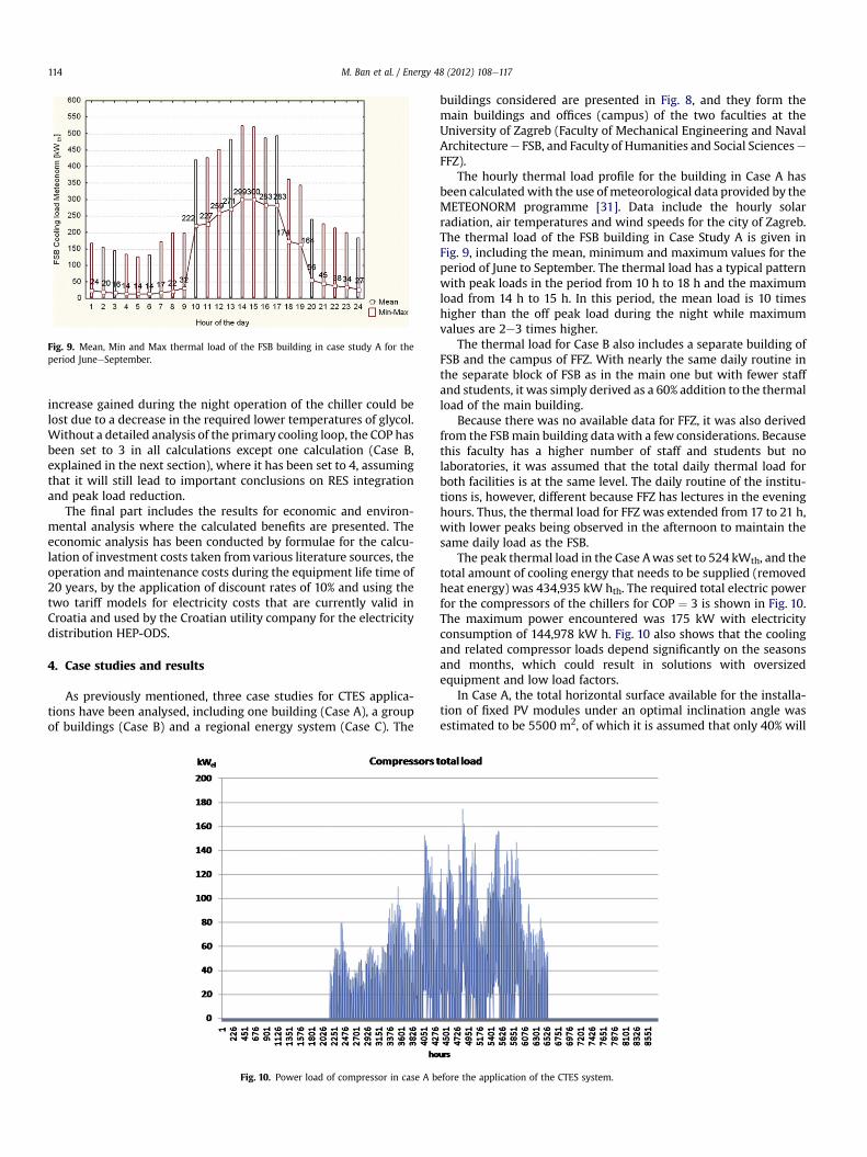
Fig. 9. Mean, Min and Max thermal load of the FSB building in case study A for theperiod JuneeSeptember.
M. Ban et al. / Energy 48 (2012) 108e117114
increase gained during the night operation of the chiller could belost due to a decrease in the required lower temperatures of glycol.Without a detailed analysis of the primary cooling loop, the COP hasbeen set to 3 in all calculations except one calculation (Case B,explained in the next section), where it has been set to 4, assumingthat it will still lead to important conclusions on RES integrationand peak load reduction.
The final part includes the results for economic and environ-mental analysis where the calculated benefits are presented. Theeconomic analysis has been conducted by formulae for the calcu-lation of investment costs taken fromvarious literature sources, theoperation and maintenance costs during the equipment life time of20 years, by the application of discount rates of 10% and using thetwo tariff models for electricity costs that are currently valid inCroatia and used by the Croatian utility company for the electricitydistribution HEP-ODS.
4. Case studies and results
As previously mentioned, three case studies for CTES applica-tions have been analysed, including one building (Case A), a groupof buildings (Case B) and a regional energy system (Case C). The
Fig. 10. Power load of compressor in case A b
buildings considered are presented in Fig. 8, and they form themain buildings and offices (campus) of the two faculties at theUniversity of Zagreb (Faculty of Mechanical Engineering and NavalArchitecturee FSB, and Faculty of Humanities and Social ScienceseFFZ).
The hourly thermal load profile for the building in Case A hasbeen calculatedwith the use of meteorological data provided by theMETEONORM programme [31]. Data include the hourly solarradiation, air temperatures and wind speeds for the city of Zagreb.The thermal load of the FSB building in Case Study A is given inFig. 9, including the mean, minimum and maximum values for theperiod of June to September. The thermal load has a typical patternwith peak loads in the period from 10 h to 18 h and the maximumload from 14 h to 15 h. In this period, the mean load is 10 timeshigher than the off peak load during the night while maximumvalues are 2e3 times higher.
The thermal load for Case B also includes a separate building ofFSB and the campus of FFZ. With nearly the same daily routine inthe separate block of FSB as in the main one but with fewer staffand students, it was simply derived as a 60% addition to the thermalload of the main building.
Because there was no available data for FFZ, it was also derivedfrom the FSBmain building datawith a few considerations. Becausethis faculty has a higher number of staff and students but nolaboratories, it was assumed that the total daily thermal load forboth facilities is at the same level. The daily routine of the institu-tions is, however, different because FFZ has lectures in the eveninghours. Thus, the thermal load for FFZ was extended from 17 to 21 h,with lower peaks being observed in the afternoon to maintain thesame daily load as the FSB.
The peak thermal load in the Case Awas set to 524 kWth, and thetotal amount of cooling energy that needs to be supplied (removedheat energy) was 434,935 kW hth. The required total electric powerfor the compressors of the chillers for COP ¼ 3 is shown in Fig. 10.The maximum power encountered was 175 kW with electricityconsumption of 144,978 kW h. Fig. 10 also shows that the coolingand related compressor loads depend significantly on the seasonsand months, which could result in solutions with oversizedequipment and low load factors.
In Case A, the total horizontal surface available for the installa-tion of fixed PV modules under an optimal inclination angle wasestimated to be 5500 m2, of which it is assumed that only 40% will
efore the application of the CTES system.

Fig. 11. Potential thermal energy excess and shortage in case A for 360 kW (2200 m2) of installed PV and COP ¼ 3 for chillers (compressors) that only use PV electricity for cooling.
M. Ban et al. / Energy 48 (2012) 108e117 115
be covered by PV (the module surface), due to shadowing, differentobstacles and building code requirements. The similar total surfacein Case B was 11,000 m2, or 4400 m2 of the surface of the PVmodule. Data for the hourly solar radiation on the horizontalsurface for Zagreb have been obtained from the METENORM pro-gramme and have been adjusted by H2RES and PV-GIS [32] pro-grammes for radiation at the optimal angle. The total yearlyradiation on the horizontal surface was 1210 kW h/m2 or, at anoptimal angle,1366 kW h/m2. PV-GIS provides values of 1190 kW h/m2 and 1350 kW h/m2, respectively. The solar atlas of Republic ofCroatia by Mati�c [33] gives a value of 1220 kW h/m2 for Zagreb.PVeGIS also provides the optimised slope and tracking around thevertical axis equal to 1670 kW h/m2, tracking around the horizontalaxis gives 1660 kW h/m2, and two-axis tracking provides a value of1700 kW h/m2. Fig. 11 shows theoretically available cooling thermalenergy excess and shortage if all electricity is used by thecompressors. The potential is approximately 3 times higher thanthe cooling load requirements with approximately 20% unsatisfiedcooling, which is mostly due to the night loads.
The results of calculations for Case A show that there were nomajor savings achieved by the installation of CTES because the
Fig. 12. Calculated total yearly costs for case A, where operation strategy ¼ night.
installation costs of CTES overreached the benefits achieved byshifting the operation of compressors in the night mode. The totalyearly costs of installation without storage were 27,301 EUR, whichincludes 20,122 EUR for electricity cost according to the “red tariffmodel” applicable to FSB and 6690 EUR for discounted yearlyinstallation and operation and maintenance costs for 2 � 90 kWcompressors. The smallest CTES installation decreased the costs ofelectricity by 40 EUR, and the difference between the high tariff andlow tariff period is at 1.5 cEUR/kW h, which means that the oper-ation strategy of CTES was not optimised theoretically. If it ispossible to utilise all of the CTES capacity to shift the loads to thelow tariff period during the 182 cooling days, then the hypotheticalmaximal achieved savings are 273 EUR. Figs. 12e15 present theincrease of the total yearly costs and total electricity costs forvarious sizes of compressors and CTES.
Assuming that a 2% unsatisfied cooling load on a yearly basis isacceptable, there are many options for district cooling systems tosatisfy the majority of cooling needs with PV panels installed on the
Fig. 13. Total electricity cost in case A, where operation strategy ¼ night.

Fig. 14. Percentage of unsatisfied load for Case B and the RES operation strategy.
Fig. 15. Total yearly electricity cost in case A and the operation strategy RES þ night.
Fig. 17. Intermittent limit and excess available for storage.
M. Ban et al. / Energy 48 (2012) 108e117116
roofs of the buildings analysed. Unfortunately, this option is noteconomically attractive because at this moment, the prices of CTESand PV are too high.
The financially most attractive option has been calculated byapplying the RES þ night operation strategy to Case A. Using thisstrategy, CTES was charged during the night, while all PV electricitywas sold to the grid with assumed feed in tariff for support of theproduction of electricity by building integrated PV at 32.22 cEUR/
Fig. 16. Regional power system load r
kW h. In this case, for the optimal solution, the total discountedyearly installation and O and M costs were 142,284 EUR, while theincome from PV production was 144,618 EUR, with an additional17,431 EUR of electricity costs that should be charged. Thus, eventhis solution is not economically feasible under the presentcircumstances. Moreover, the feed in tariff is given only for 12years; therefore, even with the calculated increase in electricitycosts in the period after the tariff is given, the present value of theproject is �181,705 EUR for a 20-year period.
The regional cooling load used in the calculations of Case C hasbeen extracted from the load of the Croatian power system. It wasassumed that the regional power load is one half of the Croatiansystem load and that the electric power related to space cooling(Figs. 16 and 17) is equal to a certain percentage of the load thatdepends on the outdoor temperature. The installed power of windturbines in the regionwas 1000MW, and the power of solar PV was54 MW. The potential for storage from intermittent sources hasbeen calculated according to the current limit of intermittent RESpenetration set by the Croatian utility to 360 MW.
The assumed cooling thermal load was 682 GW h, and thethermal power 577 MW. By incorporating 7500 MW h of CTES, therejected excess has been reduced by 78% (compared to valueswithout the storage). Taking into account a specific CO2 emissionfactor 0.33 kg/kW h per total electricity production in Croatia in theperiod from 2005 to 2010 [34], reduced emissions due to coveringof regional cooling thermal load by intermittent RES are 75110 tCO2. Calculated reduction is valid with the assumption that eachkW h of electricity from RES replaced one kW h generated inCroatia. From the global point of view reduction of CO2 emissionsmay be even higher if import of electricity from the regions withdominant coal power plants were replaced. Similar to reduction ofCO2 emissions SO2, NOx and particle emission could be estimated.
elated to space cooling in case C.
M. Ban et al. / Energy 48 (2012) 108e117 117
5. Conclusion
The work in this paper investigated the potential of using CTEScombined with RES for cooling needs in the building sector. Asreference cases, the campuses of the Faculty of Mechanical Engi-neering and Naval Architecture and the neighbouring Faculty ofHumanities and Social Studies have been used to validate theprinciples of CTES modelling for a single building and also fora district cooling system.
A simplified mathematical model has been developed for theCTES system and combined with existing H2RES software, which isused to analyse hourly system for one ormore buildings. The resultsfor the overall energy efficiency, cost effectiveness and environ-mental impact have been presented.
It was shown that the cooling and related compressor loadsdepend significantly on the seasons andmonths, which could resultin oversized equipment with low load factors.
PV tracking options have not been included in the analysisbecause they will require an additional optimisation process thatwill take into account additional surfaces and costs related to thosesystems. In addition, as shown by the use of the daily peak limit forCTES charge and discharge, the system operation could be addi-tionally optimised, but it require more detailed models.
Several test strategies have been considered, and the oneproviding the best results was with CTES charged during the nightwhile all PV electricity is sold to the grid according to the Croatianfeed in tariffs for the support of the production of RES electricity.
It will definitely be worth calculating a case with batteries,which will be more expensive, but if larger COPs could be achieved,for example, with underground water to cool the chillers, andelectric vehicles pushing the battery industry to cut the cost of theirproduction, perhaps batteries are also attractive for storage andcould be coupled with chillers to serve the cooling load efficientlyby storing the PV excess production, overall representing a veryinteresting topic for future work.
References
[1] EC - Directorate General for Energy. Expert workshop on the comparativeframework methodology for cost optimal minimum energy performancerequirements. Meeting document. Brussels: European Comission; 2011.
[2] Fraunhofer Institut. Study on energy savings potentials in EU member states,candidate countries and EEA countries. Project Final report. Karlsruhe/Gre-noble/Rome/Vienna/Wuppertal: Fraunhofer-Institute for Systems and Inno-vation Research; 2009. TREN/D1/239e2006/S07.66640.
[3] European Parliament. Directive on the energy performance of buildings.Directive. Brussels: Official Journal of the European Union; 2010. EuropeanParliament and the Council. 2010/31/EU.
[4] Grozdek M. Load shifting and storage of cooling energy through ice bank or iceSlurry systems. PhD Thesis. Stockholm: KTH; 2009 Royal Institute of tech-nology. ISBN 978-91-7415-434-4.
[5] Puk�sec T, Mathiesen BV, Dui�c N. Potentials for energy savings and long termenergy demand of Croatian households sector. Applied Energy, in press.
[6] ASHRAE. Thermal storage. In: ASHRAE handbook. Atlanta, USA: AmericanSociety of Heating, Refrigerating, and Air-Conditioning Engineering, Inc;2007.
[7] Andrepont JS. Development in thermal energy storage: large applications, lowtemps, high efficiency and capital savings. In: Proceedings of Association ofenergy Engineers (AEE) world energy Engineering Congress; 2005.
[8] Tariff models and prices. [Internet]. [Cited 2011]. Available from: http://www.hep.hr/ods/en/customers/Tariff.aspx.
[9] Croatian Power System, daily power load curve. [Internet]. [Cited 2008].Available from: http://www.hep.hr/ops/hees/dijagram.aspx.
[10] Lund H, Kempton W. Integration of renewable energy into the transport andelectricity sectors through V2G. Energy Policy 2008;36(9):3578e87.
[11] Kraja�ci�c G, Dui�c N, Tsikalakis A, Zoulias M, Caralis G, Panteri E, et al. Feed-intariffs for promotion of energy storage technologies. Energy Policy 2011;39(3):1410e25.
[12] Kraja�ci�c G, Martins R, Busuttil A, Dui�c N, Carvalho MG. Hydrogen as an energyvector in the islands’ energy supply. International Journal of Hydrogen Energy2008 February;33(4):1091e103.
[13] Kraja�ci�c G, Dui�c N, Zmijarevi�c Z, Vad Mathiesen B, Ani�c Vu�cini�c A,Carvalho MDG. Planning for a 100% independent energy system based onsmart energy storage for integration of renewables and CO2 emissionsreduction. Applied Thermal Engineering 2011;31:2073e83.
[14] Kraja�ci�c G, Dui�c N, Carvalho MG. How to achieve a 100% RES electricity supplyfor Portugal? Applied Energy 2011;88:508e17.
[15] Intelligent Energy Europe programme. Implementing the energy performanceof buildings directive (EPBD). Brussels: European Union Publications Office;2011.
[16] ENTSO-E. Resources. [Internet]. [Cited 2010 April 10]. Available from: https://www.entsoe.eu/.
[17] Croatian Hydro Meteorological Institute. Dr�zavni hidrometeorolo�ski zavod -Klimatologija. [Internet]. [Cited 2011 March]. Available from: http://klima.hr/ocjene_arhiva.php.
[18] Karad�za N, Horváth L, Mati�c Z. Progress of wind resource assessment programin Croatia. In: European Wind Energy Conference & Exhibition; 31 Marche3April 2008; Brussels Expo, Belgium. p. http://www.ewec2008proceedings.info/index2.php?page¼searchresult&searchin¼2.
[19] Dincer I, Rosen MA. Thermal energy storage: systems and applications. 2nded. Chennai: John Wiley & Sons Ltd; 2011.
[20] CRYOGEL. CRYOGEL Thermal energy storage. [Internet]. [Cited 2011 May].Available from: http://www.cryogel.com/.
[21] Cristopia Energy Systems. Cristopia energy systems. [Internet]. [Cited May2011]. Available from: http://www.cristopia.com/.
[22] Hanson SS. District cooling systems. In: Capehart BL, editor. Encyclopedia ofenergy engineering and technology, Vols. IeIII. Boca Raton: Taylor & FrancisGroup, LLC; 2007.
[23] Dincer I, Hepbasli A. District energy systems. In: Encyclopedia of energyengineering and technology, Vols. IeIII. Boca Raton: Taylor & Francis Group,LLC; 2007.
[24] Hasnain SM. Review on sustainable thermal energy storage technologies. PartII: cool thermal storage. Energy Conversation and Management 1998;39(11):1139e53.
[25] Kraja�ci�c G, Dui�c N, Carvalho MG. H2RES, Energy planning tool for islandenergy systems e the case of the Island of Mljet. International Journal ofHydrogen Energy 2009 August;34(16):7015e26.
[26] Lund H, Duic N, Krajacic G, Carvalho MG. Two energy system analysis models:a comparison of methodologies and results. Energy 2007;32(6):948e54.
[27] Bédécarrats JP, Castaing-Lasvignottes J, Strub F, Dumas JP. Study of a phasechange energy storage using spherical capsules. Part I: experimental results.Energy Conversion and Management 2009;50:2527e36.
[28] Bédécarrats JP, Castaing-Lasvignottes J, Strub F, Dumas JP. Study of a phasechange energy storage using spherical capsules. Part II: numerical modelling.Energy Conversion and Management 2009;50:2537e46.
[29] Wei J, Kawaguchi Y, Hirano S, Takeuchi H. Study on a PCM heat storage systemfor rapid heat supply. Applied Thermal Engineering 2005;25(17e18):2903e20.
[30] Assis E, Katsman L, Ziskind G, Letan R. Numerical and experimental study ofmelting in a spherical shell. International Journal of Heat and Mass Transfer2006;50(9e10):1790e804.
[31] METEOTEST. METEONORM. [Internet]. Available from: http://www.meteonorm.com/pages/en/meteonorm.php.
[32] JRC. GIS Assessment of Solar Energy Resource in Europe. [Internet]. [Cited2010 May 10]. Available from: http://re.jrc.cec.eu.int/pvgis/pv/index.htmd.
[33] Mati�c Z. Solar radiation atlas for the area of the Republic of Croatia. In:Proceedings of the first International Forum of the renewable energy sources;2004.
[34] Energy in Croatia e annual energy report. Zagreb: Ministry of Economy,Labour and Entrepreneurship, Republic of Croatia; 2011.