the rio de janeiro state university - uerj laboratory of...
TRANSCRIPT
The Rio de Janeiro State University - UERJ Laboratory of Photogrammetry and Remote SensingThe E-Foto projectPhototriangulationAuthors: Lia de Souza e Simões Figueiredo and Patricia Farias ReolonRevision: Jorge Luís Nunes e Silva Brito
Introduction
Photogrammetry aims to the reconstruction of the 3D object-space from the 2D
image-space, thus leading to the computation of reliable, indirect measurements of 3D
coordinates in the object-space with known precision. There are three types of
photogrammetric measurements: from orbital, optical imagery; form airborne imagery, and
from close-range photographs. There are also special applications such as the
measurements derived from medical imagery.
The image-space is formed from photographs taken with both forward and side-lap
superposition. The forward superposition is necessary for stereoscopic purposes; the side-
lap superposition guarantees the connection between strips of photographs. This is
mandatory for topographic photogrammetric mapping. The values of those superpositions
usually adopted in photogrammetric projects are 60% in the direction of flight (forward
superposition), and 20% to 30% in the side-lap direction. Those values can vary based
upon technical requirements of a photogrammetric mapping project.
Phototriangulation is the technique of computation of least squares adjustment of
the 3D coordinates of the perspective centers of the photographs in the object-space or in
any external reference frame. This process also calculates the Euler angles or the sensor
attitude parameters for each image of a photogrammetric block of photographs. 3D
coordinates of photogrammetric points, those that are measured only in the image space,
are also accurately computed in the phototriangulation procedure.
There are basically two approaches for computation of phototriangulation: the adjustment
by independent models and the bundle block adjustment procedures. The former method
uses a stereo-model as its basic unit of adjustment; the bundle-block adjustment, also
known as the multiple spatial resection, on the other hand, considers a light-ray connecting
a point in the object-space, the principal point of the camera, and the projection of the
point into the image-space, as its essential element for Leastsquares adjustment
computations. Therefore, a bundle of light rays forms the block of images, which is
Jun 15, 2016 Page 1 of 15
The Rio de Janeiro State University - UERJ Laboratory of Photogrammetry and Remote SensingThe E-Foto projectPhototriangulationAuthors: Lia de Souza e Simões Figueiredo and Patricia Farias ReolonRevision: Jorge Luís Nunes e Silva Brito
adjusted in a unique procedure. If a block has only one single image, the bundle-block
adjustment procedure is named “spatial resection”.
The e-foto software uses the bundle-block adjustment procedure for airborne
imagery, taken either from digital frame photogrammetric cameras or from digitalized-
frame, aerial film cameras. Further details are available in SILVEIRA, F. J. C. (2004).
Jun 15, 2016 Page 2 of 15
The Rio de Janeiro State University - UERJ Laboratory of Photogrammetry and Remote SensingThe E-Foto projectPhototriangulationAuthors: Lia de Souza e Simões Figueiredo and Patricia Farias ReolonRevision: Jorge Luís Nunes e Silva Brito
Execution
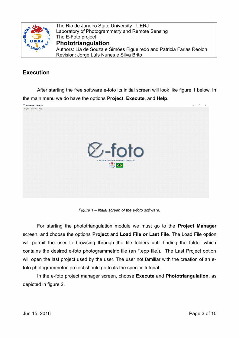
After starting the free software e-foto its initial screen will look like figure 1 below. In
the main menu we do have the options Project, Execute, and Help.
Figure 1 – Initial screen of the e-foto software.
For starting the phototriangulation module we must go to the Project Manager
screen, and choose the options Project and Load File or Last File. The Load File option
will permit the user to browsing through the file folders until finding the folder which
contains the desired e-foto photogrammetric file (an *.epp file.). The Last Project option
will open the last project used by the user. The user not familiar with the creation of an e-
foto photogrammetric project should go to its the specific tutorial.
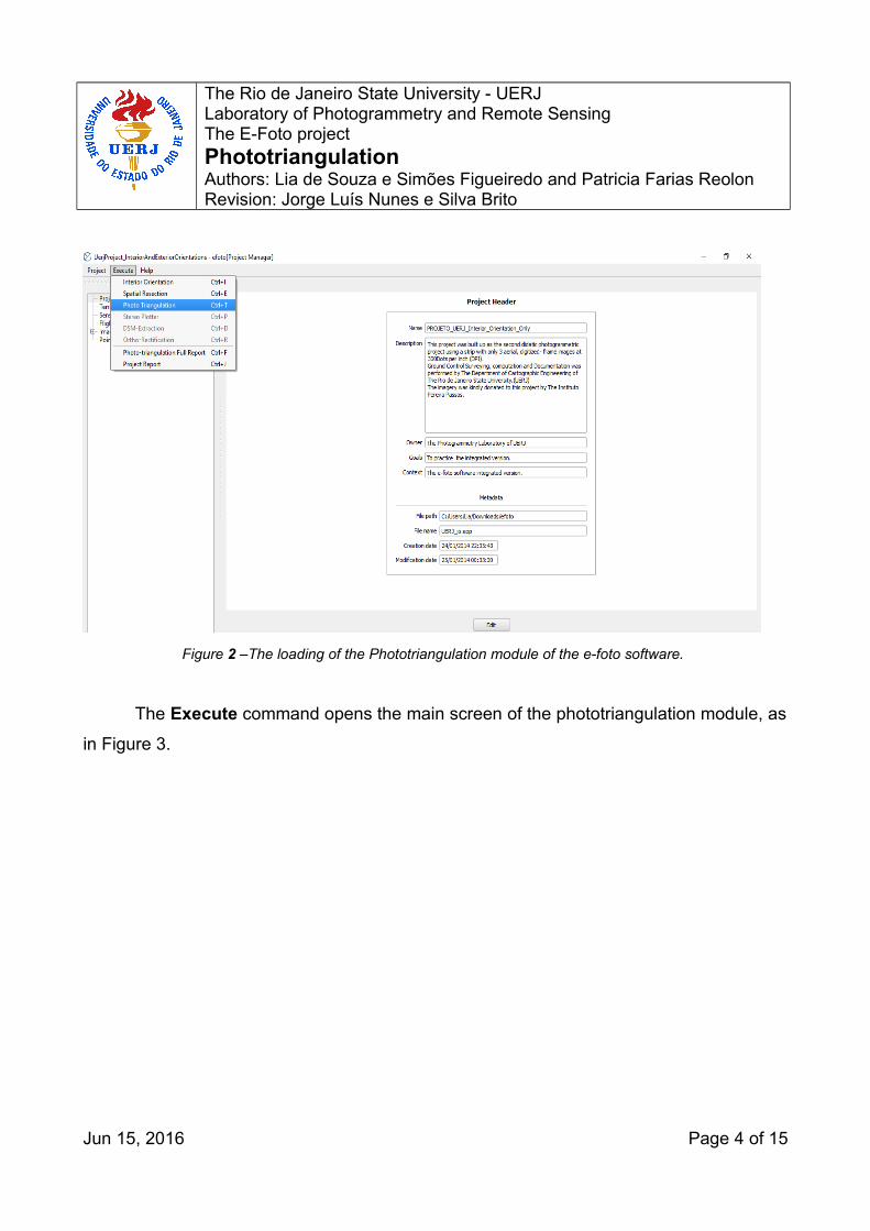
In the e-foto project manager screen, choose Execute and Phototriangulation, as
depicted in figure 2.
Jun 15, 2016 Page 3 of 15
The Rio de Janeiro State University - UERJ Laboratory of Photogrammetry and Remote SensingThe E-Foto projectPhototriangulationAuthors: Lia de Souza e Simões Figueiredo and Patricia Farias ReolonRevision: Jorge Luís Nunes e Silva Brito
Figure 2 –The loading of the Phototriangulation module of the e-foto software.
The Execute command opens the main screen of the phototriangulation module, as
in Figure 3.
Jun 15, 2016 Page 4 of 15

The Rio de Janeiro State University - UERJ Laboratory of Photogrammetry and Remote SensingThe E-Foto projectPhototriangulationAuthors: Lia de Souza e Simões Figueiredo and Patricia Farias ReolonRevision: Jorge Luís Nunes e Silva Brito
Figure 3 – The main screen of the phototriangulation module.
There are three types of viewports in the main screen of the phototriangulation
module: two viewports are for overviewing of the left and right images currently in use, two
for performing the measurements of photo coordinates of photogrammetric, checking, and
ground control points, and two for the detailed view of measuring areas in both left and
right images.
The meanings of the labels of the tables contained in the lower part of the main
window of the phototriangulation module are listed below:
• Left Image Points: This table contains the list of points measured in the left image.
Going downward in this table, we find the image file name (i.e.,
1997_016_300dpi.bmp), the list of points measured in that image (Id), and their pixel
(Column, Line) coordinates.
• All Registered Points: This table contains the list of points (Id) measured in both
images, their type (Ground Control, Photogrammetric, or Checking Point.) Ground
Jun 15, 2016 Page 5 of 15
The Rio de Janeiro State University - UERJ Laboratory of Photogrammetry and Remote SensingThe E-Foto projectPhototriangulationAuthors: Lia de Souza e Simões Figueiredo and Patricia Farias ReolonRevision: Jorge Luís Nunes e Silva Brito
coordinates (i.e., UTM coordinates and Height above Sea level) are also listed for
each point.
• Right Image Points: This table contains the list of points measured in the right
image. Going downward in this table, we find the image file name (i.e.,
1997_017_300dpi.bmp), the list of points measured in that image (Id), and their pixel
(Column, Line) coordinates.
• Image Measurements: Given a point selected in the previous tables, this table shows
the list of images where this point was measured (where it appears), as well as the
respective pixel coordinates in each image.
After finishing the photogrammetric measurements it is time to execute the
phototriangulation computations.
NOTE: Starting with the <2016-05-19> version of the e-foto software there will no
longer necessary to indicate flight direction for every image of a block. The e-foto
assumes that every project was flown “N” to “S” and “W” to “E”.
Please notice that hereafter, the e-foto phototriangulation module assumes that
every flight direction is initialized with 0°. If your project does not correspond to this
situation, you must reorganize it such that this condition is satisfied. This approach does
not interfere in the computation of ground coordinates of photogrammetric points of your
block.
Please click on the button to compute the bundle block adjustment of your
photogrammetric project.
In a common photogrammetric working flow the user may need to include some
photogrammetric points in each image of the block. Those points shall be strategically
located, such that they can act either as tie points, connecting one image to its neighbor,
forming strips of photographs, or as passing points, connecting the strips to each other,
thus assembling the whole block of photographs. In this hypothesis it will be necessary to
Jun 15, 2016 Page 6 of 15
The Rio de Janeiro State University - UERJ Laboratory of Photogrammetry and Remote SensingThe E-Foto projectPhototriangulationAuthors: Lia de Souza e Simões Figueiredo and Patricia Farias ReolonRevision: Jorge Luís Nunes e Silva Brito
go to the point insertion mode. For doing so, the user must click on the Insert
Photogrammetric Point button. There are some buttons designed to facilitate the
phototriangulation point measurement procedure.
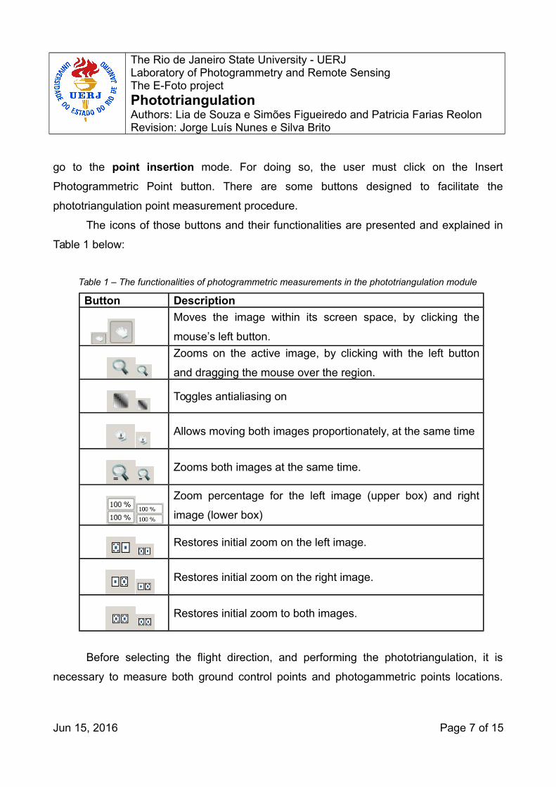
The icons of those buttons and their functionalities are presented and explained in
Table 1 below:
Table 1 – The functionalities of photogrammetric measurements in the phototriangulation module
Button Description Moves the image within its screen space, by clicking the
mouse’s left button.
Zooms on the active image, by clicking with the left button
and dragging the mouse over the region.
Toggles antialiasing on
Allows moving both images proportionately, at the same time
Zooms both images at the same time.
Zoom percentage for the left image (upper box) and right
image (lower box)
Restores initial zoom on the left image.
Restores initial zoom on the right image.
Restores initial zoom to both images.
Before selecting the flight direction, and performing the phototriangulation, it is
necessary to measure both ground control points and photogammetric points locations.
Jun 15, 2016 Page 7 of 15
The Rio de Janeiro State University - UERJ Laboratory of Photogrammetry and Remote SensingThe E-Foto projectPhototriangulationAuthors: Lia de Souza e Simões Figueiredo and Patricia Farias ReolonRevision: Jorge Luís Nunes e Silva Brito
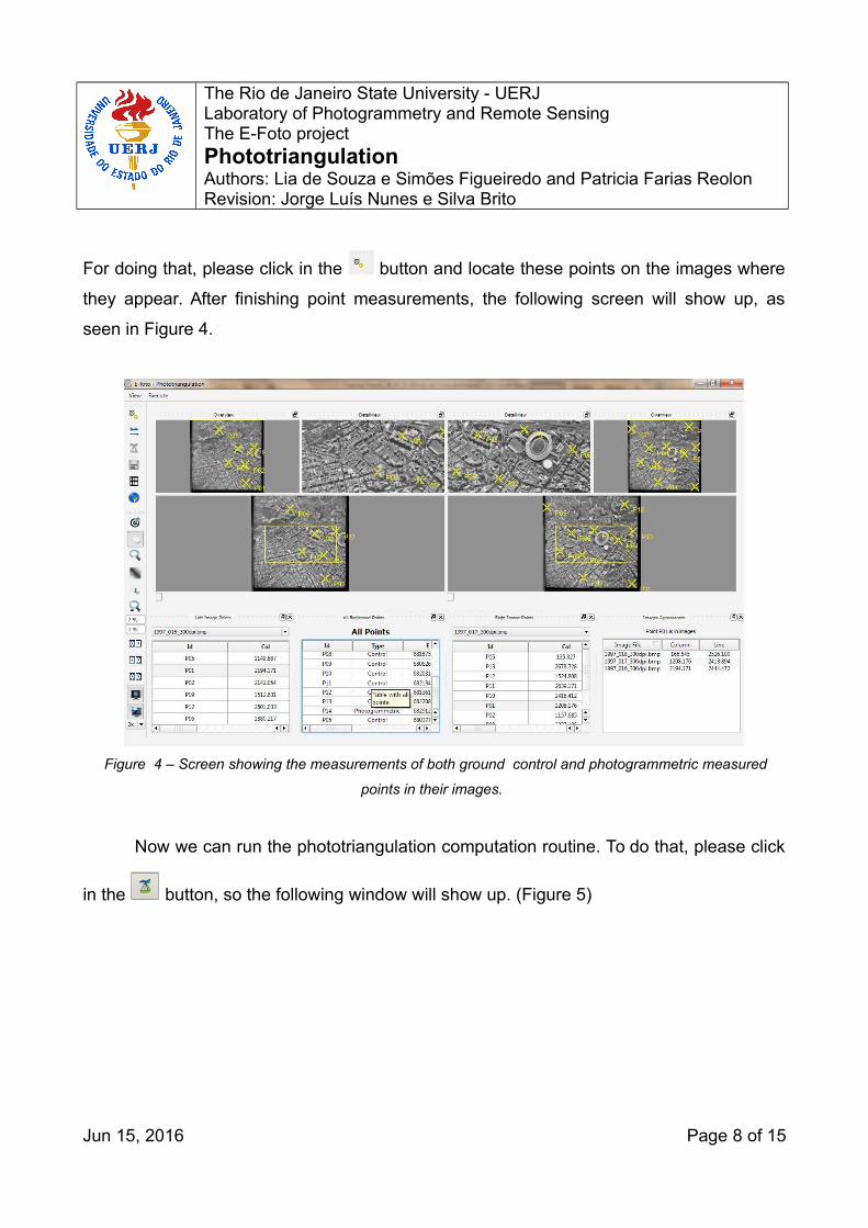
For doing that, please click in the button and locate these points on the images where
they appear. After finishing point measurements, the following screen will show up, as
seen in Figure 4.
Figure 4 – Screen showing the measurements of both ground control and photogrammetric measured
points in their images.
Now we can run the phototriangulation computation routine. To do that, please click
in the button, so the following window will show up. (Figure 5)
Jun 15, 2016 Page 8 of 15
The Rio de Janeiro State University - UERJ Laboratory of Photogrammetry and Remote SensingThe E-Foto projectPhototriangulationAuthors: Lia de Souza e Simões Figueiredo and Patricia Farias ReolonRevision: Jorge Luís Nunes e Silva Brito
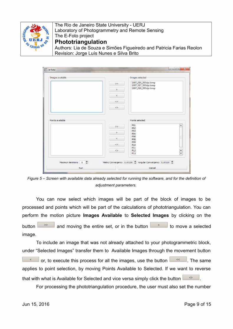
Figure 5 – Screen with available data already selected for running the software, and for the definition of
adjustment parameters.
You can now select which images will be part of the block of images to be
processed and points which will be part of the calculations of phototriangulation. You can
perform the motion picture Images Available to Selected Images by clicking on the
button and moving the entire set, or in the button to move a selected
image.
To include an image that was not already attached to your photogrammetric block,
under “Selected Images” transfer them to Available Images through the movement button
or, to execute this process for all the images, use the button . The same
applies to point selection, by moving Points Available to Selected. If we want to reverse
that with what is Available for Selected and vice versa simply click the button .
For processing the phototriangulation procedure, the user must also set the number
Jun 15, 2016 Page 9 of 15
The Rio de Janeiro State University - UERJ Laboratory of Photogrammetry and Remote SensingThe E-Foto projectPhototriangulationAuthors: Lia de Souza e Simões Figueiredo and Patricia Farias ReolonRevision: Jorge Luís Nunes e Silva Brito
of iterations to achieve convergence. This is accomplished through the combo Max
interations as well as precision values for convergence in meters, through the combo
Metric convergency and angular value through the combo Angular Convergency.
After choosing images, points and setting parameters for the maximum number of
iterations and metric and angular convergence, you must click in the button as we do
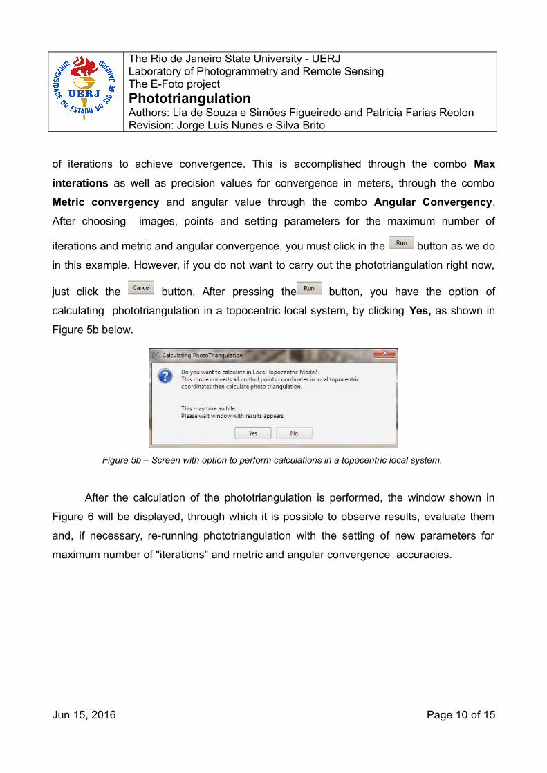
in this example. However, if you do not want to carry out the phototriangulation right now,
just click the button. After pressing the button, you have the option of
calculating phototriangulation in a topocentric local system, by clicking Yes, as shown in
Figure 5b below.
Figure 5b – Screen with option to perform calculations in a topocentric local system.
After the calculation of the phototriangulation is performed, the window shown in
Figure 6 will be displayed, through which it is possible to observe results, evaluate them
and, if necessary, re-running phototriangulation with the setting of new parameters for
maximum number of "iterations" and metric and angular convergence accuracies.
Jun 15, 2016 Page 10 of 15
The Rio de Janeiro State University - UERJ Laboratory of Photogrammetry and Remote SensingThe E-Foto projectPhototriangulationAuthors: Lia de Souza e Simões Figueiredo and Patricia Farias ReolonRevision: Jorge Luís Nunes e Silva Brito
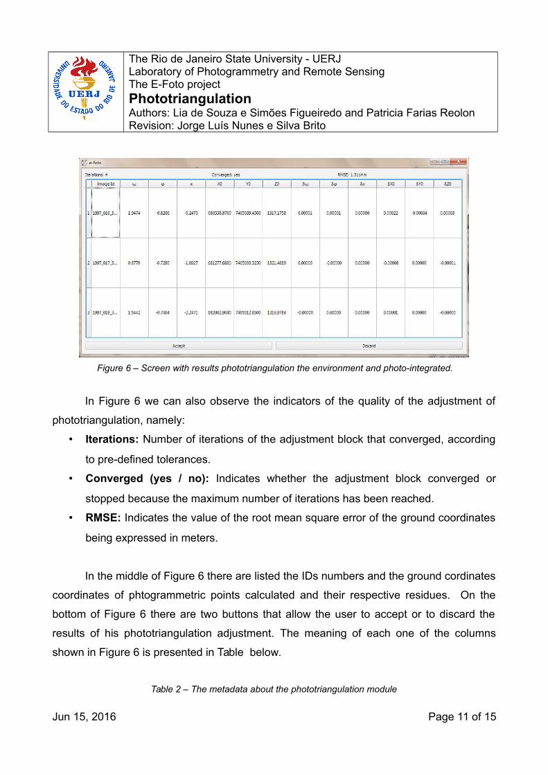
Figure 6 – Screen with results phototriangulation the environment and photo-integrated.
In Figure 6 we can also observe the indicators of the quality of the adjustment of
phototriangulation, namely:
• Iterations: Number of iterations of the adjustment block that converged, according
to pre-defined tolerances.
• Converged (yes / no): Indicates whether the adjustment block converged or
stopped because the maximum number of iterations has been reached.
• RMSE: Indicates the value of the root mean square error of the ground coordinates
being expressed in meters.
In the middle of Figure 6 there are listed the IDs numbers and the ground cordinates
coordinates of phtogrammetric points calculated and their respective residues. On the
bottom of Figure 6 there are two buttons that allow the user to accept or to discard the
results of his phototriangulation adjustment. The meaning of each one of the columns
shown in Figure 6 is presented in Table below.
Table 2 – The metadata about the phototriangulation module
Jun 15, 2016 Page 11 of 15

The Rio de Janeiro State University - UERJ Laboratory of Photogrammetry and Remote SensingThe E-Foto projectPhototriangulationAuthors: Lia de Souza e Simões Figueiredo and Patricia Farias ReolonRevision: Jorge Luís Nunes e Silva Brito
Button Description Image Id Image identifier
w (ω)(Omega) or attitude angle of image system rotation
around the X axis
Phi (ρ) attitude angle or image system rotation around Y axis
K (Κ)rotation angle of the image system around the Z axis
angle on the same direction of the flight Xo perspective center X coordinate in ground systemYo perspective center Y coordinate in ground systemZo perspective center Z coordinate in ground systemDw residual for the adjustment of the omega angle Dphi residual for the adjustment of the phi angle Dk residual for the adjustment of the kappa angle DXO residual for the adjustment of Xo in metersDYO residual for the adjustment of Yo in metersDZO residual for the adjustment of Zo in metersId Photogrammetric point identification E East coordinate (UTM) N North coordinate (UTM)
H orthometric altitude or height according to the system
adopted for the adjustment dE residual for the adjustment of the E coordinate dN residual for the adjustment of the N coordinate dH residual for the adjustment of the H coordinate
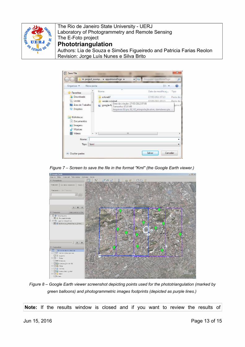
To save the results of your phototriangulation computation as a "kml" file and to
open it on GoogleEarth, just click in the button on the main screen of the
phototriangulation module. A window will appear so you can choose the file name you
want to use for saving the "kml" file, as shown in Figure 8. Browse the folder where you
wish to save the file and double-click on it. If you have Google Earth installed, it will show
the footprints of each image of your project and the position of photogrammetric control
points georreferenced by Google Earth. (Please see Figure 8)
Jun 15, 2016 Page 12 of 15
The Rio de Janeiro State University - UERJ Laboratory of Photogrammetry and Remote SensingThe E-Foto projectPhototriangulationAuthors: Lia de Souza e Simões Figueiredo and Patricia Farias ReolonRevision: Jorge Luís Nunes e Silva Brito
Figure 7 – Screen to save the file in the format "Kml" (the Google Earth viewer.)
Figure 8 – Google Earth viewer screenshot depicting points used for the phototriangulation (marked by
green balloons) and photogrammetric images footprints (depicted as purple lines.)
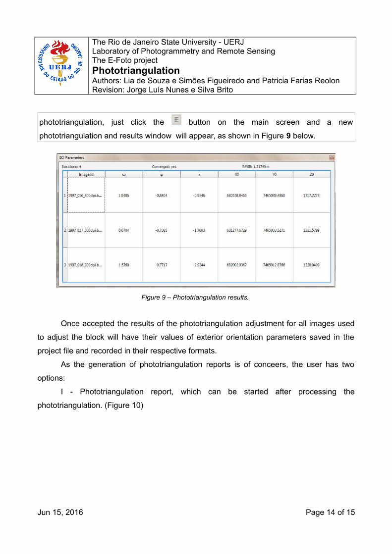
Note: If the results window is closed and if you want to review the results of
Jun 15, 2016 Page 13 of 15
The Rio de Janeiro State University - UERJ Laboratory of Photogrammetry and Remote SensingThe E-Foto projectPhototriangulationAuthors: Lia de Souza e Simões Figueiredo and Patricia Farias ReolonRevision: Jorge Luís Nunes e Silva Brito
phototriangulation, just click the button on the main screen and a new
phototriangulation and results window will appear, as shown in Figure 9 below.
Figure 9 – Phototriangulation results.
Once accepted the results of the phototriangulation adjustment for all images used
to adjust the block will have their values of exterior orientation parameters saved in the
project file and recorded in their respective formats.
As the generation of phototriangulation reports is of conceers, the user has two
options:
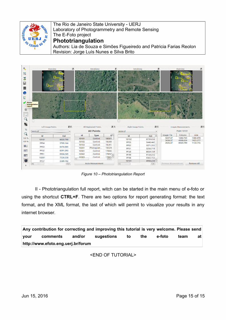
I - Phototriangulation report, which can be started after processing the
phototriangulation. (Figure 10)
Jun 15, 2016 Page 14 of 15
The Rio de Janeiro State University - UERJ Laboratory of Photogrammetry and Remote SensingThe E-Foto projectPhototriangulationAuthors: Lia de Souza e Simões Figueiredo and Patricia Farias ReolonRevision: Jorge Luís Nunes e Silva Brito
Figure 10 – Phototriangulation Report
II - Phototriangulation full report, witch can be started in the main menu of e-foto or
using the shortcut CTRL+F. There are two options for report generating format: the text
format, and the XML format, the last of which will permit to visualize your results in any
internet browser.
Any contribution for correcting and improving this tutorial is very welcome. Please send
your comments and/or sugestions to the e-foto team at
http://www.efoto.eng.uerj.br/forum
<END OF TUTORIAL>
Jun 15, 2016 Page 15 of 15