the revised msx red book
TRANSCRIPT
The Revised MSX Red Book
0. FOREWORDS
Last revision on 2005/March/31 Thursday.
Notes from the revisor:
• The book was scanned and converted (via O.C.R.) by someone in Europe (name omitted to preserve his anonymity), then edited and revised by me, working independently. For unknown reasons (though ponderable), Chapter 7 (currently renumbered to Chapter 9) was not scanned. Bad enough. It is also known that some lines had been on purpose modified just after the scanning. I tried to restore them to their original state, but without the original book, it was a quite hard task (the only support was a Portuguese translation). Anyway, the original text has been heavily revised, many informations corrected and new ones added, so it no longer matter (that much...)
• The book was converted to HTML format for viewing. Hypertext links, CSS, JavaScript and SVG were also added to make information clearer.
• This book originally only covered standard MSX. The BIOS entry points from 0000H to 01B5H should be used instead of the accessed entries described in the rest of the book, because other machines (MSX2, MSX2+, MSX turbo R and customized ones) have different positions for those routines. The use of internal BIOS routine addresses are responsible for many programs only running in some specific MSX, so it's completely deprecated.
• MSX2, MSX2+ and turbo R information has been added to make this book even more useful.
• Errors present in the original book were fixed, though it was tried to keep it as unaltered as possible. All page numbers match the originals, except undetected errors already present in the original.
• Incoherent data and some obscure parts has been changed. New data have been added from MSX Datapack and from Japan MSX Magazine, though they are not direct translations.
1. TABLE OF CONTENTS
0. Forewords
1. Table of Contents
2. Introduction
3. Programmable Peripheral Interface
4. Video Display Processor (MSX2/2+ under construction)
5. Programmable Sound Generator (under construction)
6. ROM BIOS (under construction)
7. ROM BASIC Interpreter (under construction)
8. Memory Usage Map (Workspace Area) (under construction)
9. Machine Code Programs (missing pages, read Forewords)
10. MSX2+ Hardware Schematics (from MSX Datapack, under construction)
10. Appendices (under construction)
11. Index (under construction)
Contents Copyright 1985 Avalon Software Iver Lane, Cowley, Middx, UB8 2JD MSX is a trademark of Microsoft Corp. Z80 is a trademark of Zilog Corp.
Appendices Copyright Unicorn Dreams Artwork Productions. Revised 1998-2005 by Cyberknight Masao Kawata. Based on "MSX Datapack" (Japan ASCII Co.), "MSX Technical Handbook" (Japan ASCII Co.) and Japan "MSX Magazine".
2. INTRODUCTION
Aims
This book is about MSX computers and how they work. For technical and commercial reasons MSX computer manufacturers only make a limited amount of information available to the end user about the design of their machines. Usually this will be a fairly detailed description of Microsoft MSX BASIC together with a broad outline of the system hardware. While this level of documentation is adequate for the casual user it will inevitably prove limiting to anyone engaged in more sophisticated programming.
The aim of this book is to provide a description of the standard MSX hardware and software at a level of detail sufficient to satisfy that most demanding of users, the machine code programmer. It is not an introductory course on programming and is necessarily of a rather technical nature. It is assumed that you already possess, or intend to acquire by other means, an understanding of the Z80 Microprocessor at the machine code level. As there are so many general purpose books already in existence about the Z80 any description of its characteristics would simply duplicate widely available information.
Organization
The MSX Standard specifies the following as the major functional components in any MSX computer:
1. Zilog Z80 Microprocessor 2. Intel 8255 Programmable Peripheral Interface 3. Texas 9929 Video Display Processor 4. General Instrument 8910 Programmable Sound Generator 5. 32 KB MSX-BIOS and MSX-BASIC ROM 6. 8 KB RAM minimum
Although there are obviously a great many additional components involved in the design of an MSX computer they are all small-scale, non-programmable ones and therefore "invisible" to the user. Manufacturers generally have considerable freedom in the selection of these small-scale components. The programmable components cannot be
varied and therefore all MSX machines are identical as far as the programmer is concerned.
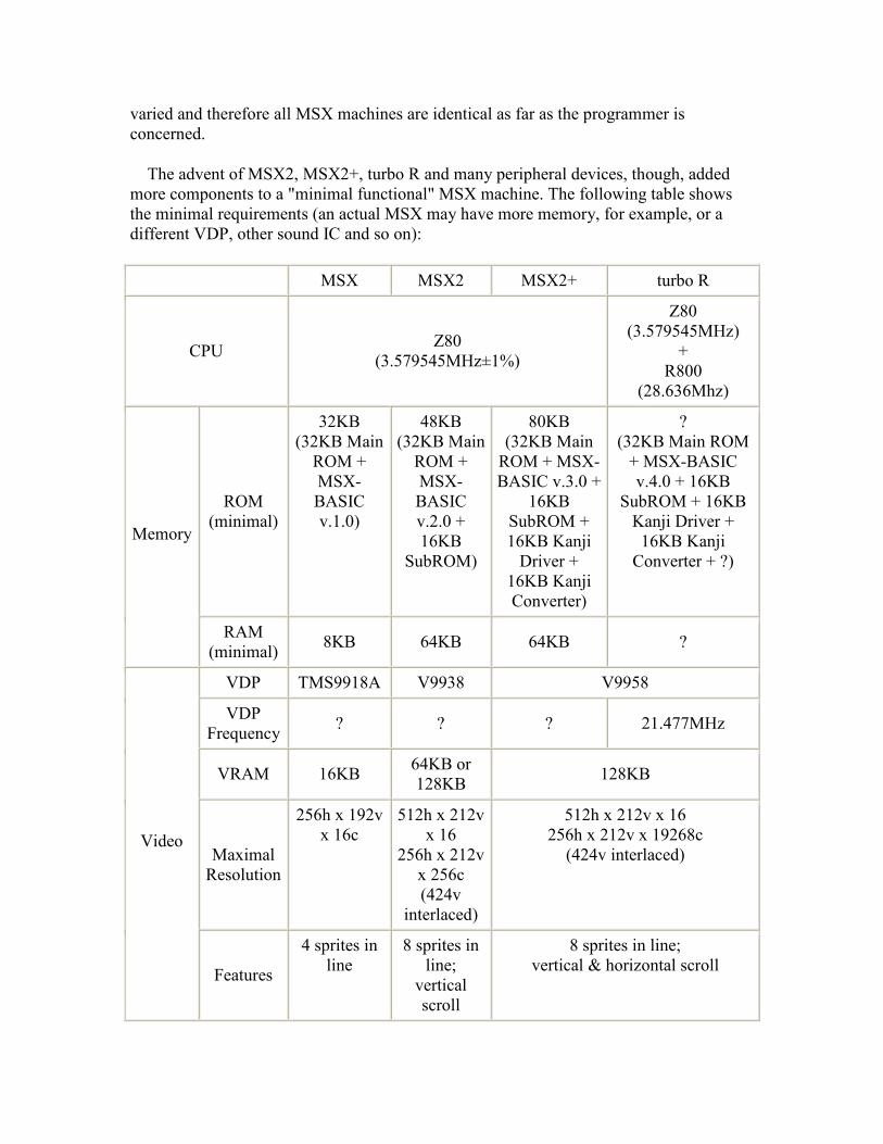
The advent of MSX2, MSX2+, turbo R and many peripheral devices, though, added more components to a "minimal functional" MSX machine. The following table shows the minimal requirements (an actual MSX may have more memory, for example, or a different VDP, other sound IC and so on):
MSX MSX2 MSX2+ turbo R
CPU Z80 (3.579545MHz±1%)
Z80 (3.579545MHz)
+ R800
(28.636Mhz)
ROM (minimal)
32KB (32KB Main
ROM + MSX-BASIC v.1.0)
48KB (32KB Main
ROM + MSX-BASIC v.2.0 + 16KB
SubROM)
80KB (32KB Main
ROM + MSX-BASIC v.3.0 +
16KB SubROM + 16KB Kanji
Driver + 16KB Kanji Converter)
? (32KB Main ROM
+ MSX-BASIC v.4.0 + 16KB
SubROM + 16KB Kanji Driver +
16KB Kanji Converter + ?)
Memory
RAM (minimal) 8KB 64KB 64KB ?
VDP TMS9918A V9938 V9958
VDP Frequency ? ? ? 21.477MHz
VRAM 16KB 64KB or 128KB 128KB
Maximal Resolution
256h x 192v x 16c
512h x 212v x 16
256h x 212v x 256c (424v
interlaced)
512h x 212v x 16 256h x 212v x 19268c
(424v interlaced) Video
Features
4 sprites in line
8 sprites in line;
vertical scroll
8 sprites in line; vertical & horizontal scroll

PSG AY-3-8910
FM - FM-PAC (extra)
MSX-Music (optional) MSX-Music Audio
PCM - 8 bits
CMT (Data-corder) 1200/2400 bps -
Keyboard 88 key matrix
Floppy Disk Drive 1DD (180KB), 2DD (360KB) or 2HD (720KB) (optional) 3.5" 2HD (720KB)
Printer (optional) 8 bits parallel Centronics
Cartridge Slot At least one slot is required
Joystick 1 (minimal) 2
Kanji ROM (optional) (optional)
Level 1 (Level 2 optional)
Level 1 + 2 Kanji
Function Kanji Input Application dependent MSX-JE MSX-JE
Real-time Clock - RPC5C01
Chapters 1, 2 and 3 describe the operation of the Programmable Peripheral Interface, Video Display Processor and Programmable Sound Generator respectively. These three devices provide the interface between the Z80 and the peripheral hardware on a standard MSX machine. All occupy positions on the Z80 I/O (Input/output) Bus.
Chapter 4 covers the software contained in the first part of the MSX ROM. This section of the ROM is concerned with controlling the machine hardware at the fine detail level and is known as the ROM BIOS (Basic Input Output System). It is structured in such a way that most of the functions a machine code programmer requires, such as keyboard and video drivers, are readily available.
Chapter 5 describes the software contained in the remainder of the ROM, the Microsoft MSX BASIC Interpreter. Although this is largely a text-driven program, and consequently of less use to the programmer, a close examination reveals many points not documented by manufacturers.
Chapter 6 is concerned with the organization of system memory. Particular attention is paid to the Workspace Area, that section of RAM from F380H to FFFFH, as this is used as a scratchpad by the BIOS and the BASIC Interpreter and contains much information of use to any application program.
Chapter 7 gives some examples of machine code programs that make use of ROM features to minimize design effort.
It is believed that this book contains zero defects, if you know otherwise the author would be delighted to hear from you. This book is dedicated to those people interested in solving problems hard to solve.
This revised version of the book is dedicated to the Light, without which we would be all blind... - The Revisor.
3. PROGRAMMABLE PERIPHERAL INTERFACE
The 8255 PPI is a general purpose parallel interface device configured as three eight bit data ports, called A, B and C, and a mode port. It appears to the Z80 as four I/O ports through which the keyboard, the memory switching hardware, the cassette motor, the cassette output, the Caps Lock LED and the Key Click audio output can be controlled. Once the PPI has been initialized access to a particular piece of hardware just involves writing to or reading the relevant I/O port.
PPI Port A (I/O Port A8H)
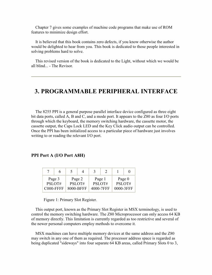
7 6 5 4 3 2 1 0
Page 3 PSLOT#
C000-FFFF
Page 2 PSLOT#
8000-BFFF
Page 1 PSLOT#
4000-7FFF
Page 0 PSLOT#
0000-3FFF
Figure 1: Primary Slot Register.
This output port, known as the Primary Slot Register in MSX terminology, is used to control the memory switching hardware. The Z80 Microprocessor can only access 64 KB of memory directly. This limitation is currently regarded as too restrictive and several of the newer personal computers employ methods to overcome it.
MSX machines can have multiple memory devices at the same address and the Z80 may switch in any one of them as required. The processor address space is regarded as being duplicated "sideways" into four separate 64 KB areas, called Primary Slots 0 to 3,

each of which receives its own slot select signal alongside the normal Z80 bus signals. The contents of the Primary Slot Register determine which slot select signal is active and therefore which Primary Slot is selected.
To increase flexibility each 16 KB "page" of the Z80 address space may be selected from a different Primary Slot. As shown in Figure 1 two bits of the Primary Slot Register are required to define the Primary Slot number for each page.
The first operation performed by the MSX ROM at power-up is to search through each slot for RAM in pages 2 and 3 (8000H to FFFFH). The Primary Slot Register is then set so that the relevant slots are selected thus making the RAM permanently available. The memory configuration of any MSX machine can be determined by displaying the Primary Slot Register setting with the BASIC statement:
PRINT RIGHT$("0000000"+BIN$(INP(&HA8)),8)
As an example "10100000" would be produced on a Toshiba HX10 where pages 3 and 2 (the RAM) both come from Primary Slot 2 and pages 1 and 0 (the MSX ROM) from Primary Slot 0. The MSX ROM must always be placed in Primary Slot 0 by a manufacturer as this is the slot selected by the hardware at power-up. Other memory devices, RAM and any additional ROM, may be placed in any slot by a manufacturer.
A typical UK machine will have one Primary Slot containing the MSX ROM, one containing 64 KB of RAM and two slots brought out to external connectors. Most Japanese machines have a cartridge type connector on each of these external slots but UK machines usually have one cartridge connector and one IDC connector.
Expanders
System memory can be increased to a theoretical maximum of sixteen 64 KB areas by using expander interfaces. An expander plugs into any Primary Slot to provide four 64 KB Secondary Slots, numbered 0 to 3, instead of one primary one. Each expander has its own local hardware, called a Secondary Slot Register, to select which of the Secondary Slots should appear in the Primary Slot. As before pages can be selected from different Secondary Slots.
FFFFH Address
7 6 5 4 3 2 1 0
Page 3 SSLOT#
Page 2 SSLOT#
Page 1 SSLOT#
Page 0 SSLOT#

C000-FFFF 8000-BFFF 4000-7FFF 0000-3FFF
Figure 2: Secondary Slot Register.
Each Secondary Slot Register, while actually being an eight bit read/write latch, is made to appear as memory location FFFFH of its Primary Slot by the expander hardware. In order to gain access to this location on a particular expander it will usually be necessary to first switch page 3 (C000H to FFFFH) of that Primary Slot into the processor address space. The Secondary Slot Register can then be modified and, if necessary, page 3 restored to its original Primary Slot setting. Accessing memory in expanders can become rather a convoluted process.
It is apparent that there must be some way of determining whether a Primary Slot contains ordinary RAM or an expander in order to access it properly. To achieve this the Secondary Slot Registers are designed to invert their contents when read back. During the power-up RAM search memory location FFFFH of each Primary Slot is examined to determine whether it behaves normally or whether the slot contains an expander. The results of these tests are stored in the Workspace Area system resource map EXPTBL for later use. This is done at power-up because of the difficulty in performing tests when the Secondary Slot Registers actually contain live settings.
Memory switching is obviously an area demanding extra caution, particularly with the hierarchical mechanisms needed to control expanders. Care must be taken to avoid switching out the page in which a program is running or, if it is being used, the page containing the stack. There are a number of standard routines available to the machine code programmer in the BIOS section of the MSX ROM to simplify the process.
The BASIC Interpreter itself has four methods of accessing extension ROMs. The first three of these are for use with machine code ROMs placed in page 1 (4000H to 7FFFH), they are:
1. Hooks. 2. The "CALL" statement. 3. Additional device names (Chapter 5).
The BASIC Interpreter can also execute a BASIC program ROM detected in page 2 (8000H to BFFFH) during the power-up ROM search. What the BASIC Interpreter cannot do is use any RAM hidden behind other memory devices. This limitation is a reflection of the difficulty in converting an established program to take advantage of newer, more complex machines. A similar situation exists with the version of Microsoft BASIC available on the IBM PC. Out of a 1 MB memory space only 64 KB can be used for program storage.
PPI Port B (I/O Port A9H)

7 6 5 4 3 2 1 0
Keyboard Column Inputs
Figure 3.
This input port is used to read the eight bits of column data from the currently selected row of the keyboard. The MSX keyboard is a software scanned eleven row by eight column matrix of normally open switches. Current machines usually only have keys in rows zero to eight. Conversion of key depressions into character codes is performed by the MSX ROM interrupt handler, this process is described in Chapter 4.
PPI Port C (I/O Port AAH)
7 6 5 4 3 2 1 0
Key Click
Cap LED
Cas Out
Cas Motor Keyboard Row Select
Figure 4.
This output port controls a variety of functions. The four Keyboard Row Select bits select which of the eleven keyboard rows, numbered from 0 to 10, is to be read in by PPI Port B. Some MSX machines may have more keyboard lines, from 11 till 15, which should be read directly by accessing the PPI ports, because they are not normally scanned by MSX-BIOS (there isn't space reserved in memory keyboard buffers OLDKEY and NEWKEY for those extra lines).
The Cas Motor bit determines the state of the cassette motor relay: 0=On, 1=Off.
The Cas Out bit is filtered and attenuated before being taken to the cassette DIN socket as the MIC signal. All cassette tone generation is performed by software.
The Cap LED bit determines the state of the Caps Lock LED: 0=On, 1=Off.
The Key Click output is attenuated and mixed with the audio output from the Programmable Sound Generator. To actually generate a sound this bit should be flipped on and off.
Note that there are standard routines in the ROM BIOS to access all of the functions available with this port. These should be used in preference to direct manipulation of the hardware if at all possible.
PPI Mode Port (I/O Port ABH)
This port is used to set the operating mode of the PPI. As the MSX hardware is designed to work in one particular configuration only this port should not be modified under any circumstances. Details are given for completeness only.
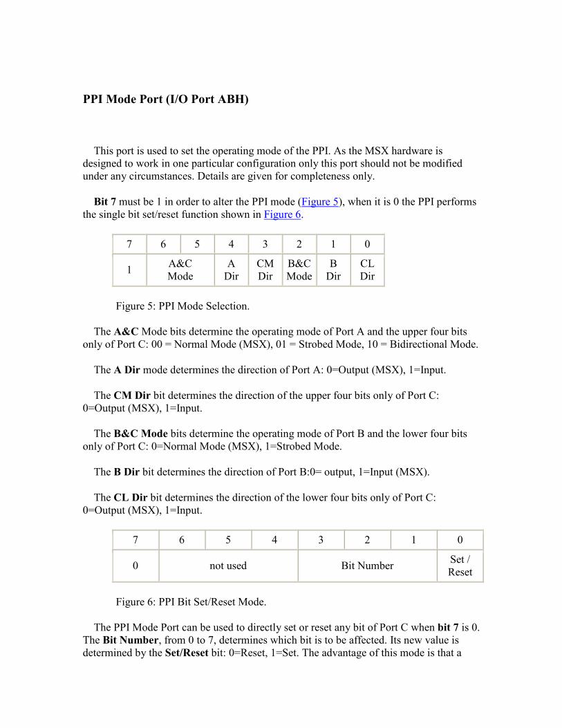
Bit 7 must be 1 in order to alter the PPI mode (Figure 5), when it is 0 the PPI performs the single bit set/reset function shown in Figure 6.
7 6 5 4 3 2 1 0
1 A&C Mode
A Dir
CM Dir
B&C Mode
B Dir
CL Dir
Figure 5: PPI Mode Selection.
The A&C Mode bits determine the operating mode of Port A and the upper four bits only of Port C: 00 = Normal Mode (MSX), 01 = Strobed Mode, 10 = Bidirectional Mode.
The A Dir mode determines the direction of Port A: 0=Output (MSX), 1=Input.
The CM Dir bit determines the direction of the upper four bits only of Port C: 0=Output (MSX), 1=Input.
The B&C Mode bits determine the operating mode of Port B and the lower four bits only of Port C: 0=Normal Mode (MSX), 1=Strobed Mode.
The B Dir bit determines the direction of Port B:0= output, 1=Input (MSX).
The CL Dir bit determines the direction of the lower four bits only of Port C: 0=Output (MSX), 1=Input.
7 6 5 4 3 2 1 0
0 not used Bit Number Set / Reset
Figure 6: PPI Bit Set/Reset Mode.
The PPI Mode Port can be used to directly set or reset any bit of Port C when bit 7 is 0. The Bit Number, from 0 to 7, determines which bit is to be affected. Its new value is determined by the Set/Reset bit: 0=Reset, 1=Set. The advantage of this mode is that a
single output can be easily modified. As an example the Caps Lock LED may be turned on with the BASIC statement OUT &HAB,12 and off with the statement OUT &HAB,13.
4. VIDEO DISPLAY PROCESSOR
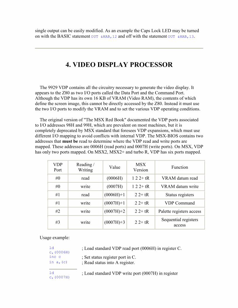
The 9929 VDP contains all the circuitry necessary to generate the video display. It appears to the Z80 as two I/O ports called the Data Port and the Command Port. Although the VDP has its own 16 KB of VRAM (Video RAM), the contents of which define the screen image, this cannot be directly accessed by the Z80. Instead it must use the two I/O ports to modify the VRAM and to set the various VDP operating conditions.
The original version of "The MSX Red Book" documented the VDP ports associated to I/O addresses 98H and 99H, which are prevalent on most machines, but it is completely deprecated by MSX standard that foresees VDP expansions, which must use different I/O mapping to avoid conflicts with internal VDP. The MSX-BIOS contains two addresses that must be read to determine where the VDP read and write ports are mapped. These addresses are 0006H (read ports) and 0007H (write ports). On MSX, VDP has only two ports mapped. On MSX2, MSX2+ and turbo R, VDP has six ports mapped.
VDP Port
Reading / Writing Value MSX
Version Function
#0 read (0006H) 1 2 2+ tR VRAM datum read
#0 write (0007H) 1 2 2+ tR VRAM datum write
#1 read (0006H)+1 2 2+ tR Status registers
#1 write (0007H)+1 2 2+ tR VDP Command
#2 write (0007H)+2 2 2+ tR Palette registers access
#3 write (0007H)+3 2 2+ tR Sequential registers access
Usage example:
ld c,(0006H)
; Load standard VDP read port (0006H) in register C.
inc c ; Set status register port in C. in a,(c) ; Read status into A register.
ld c,(0007H)
; Load standard VDP write port (0007H) in register
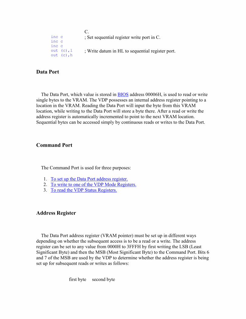
C. inc c inc c inc c
; Set sequential register write port in C.
out (c),l out (c),h
; Write datum in HL to sequential register port.
Data Port
The Data Port, which value is stored in BIOS address 00006H, is used to read or write single bytes to the VRAM. The VDP possesses an internal address register pointing to a location in the VRAM. Reading the Data Port will input the byte from this VRAM location, while writing to the Data Port will store a byte there. After a read or write the address register is automatically incremented to point to the next VRAM location. Sequential bytes can be accessed simply by continuous reads or writes to the Data Port.
Command Port
The Command Port is used for three purposes:
1. To set up the Data Port address register. 2. To write to one of the VDP Mode Registers. 3. To read the VDP Status Registers.
Address Register
The Data Port address register (VRAM pointer) must be set up in different ways depending on whether the subsequent access is to be a read or a write. The address register can be set to any value from 0000H to 3FFFH by first writing the LSB (Least Significant Byte) and then the MSB (Most Significant Byte) to the Command Port. Bits 6 and 7 of the MSB are used by the VDP to determine whether the address register is being set up for subsequent reads or writes as follows:
first byte second byte

Read: xxxxxxxx 00xxxxxx
Write: xxxxxxxx 01xxxxxx
Figure 1: VDP Address Setup.
It is important that no other accesses are made to the VDP in between writing the LSB and the MSB as this will upset its synchronization. The MSX ROM interrupt handler is continuously reading the VDP Status Register as a background task so interrupts should be disabled as necessary. It is also important to prepare VDP for reading or writing every time the program needs to change from one operation to the other, that is, a program cannot read a byte from VRAM and, without setting VDP for writing, write a byte to the next address, or write a byte to VRAM and, after that, read a byte them the next address without preparing VDP for reading.
di ; Disable all maskable interruptions. ld c,(0007H) inc c
; Load standard VDP command port (0007H)+1 in register C.
out (c),l ; Write LSB of VRAM address in HL to VDP. ld a,h ; Load MSB from VRAM addess in HL to A. and 3FH ; VRAM read mask. out (c),a ; Write MSB of VRAM address, preparing it to be read.
di ; Disable all maskable interruptions. ld c,(0007H) inc c
; Load standard VDP command port (0007H)+1 in register C.
out (c),l ; Write LSB of VRAM address in HL to VDP. ld a,h ; Load MSB from VRAM addess in HL to A. and 7FH or 40H
; VRAM write mask.
out (c),a
; Write MSB of VRAM address, preparing it for writing.
VDP Mode Registers
The VDP has forty-seven write-only registers, numbered 0 to 46, which control its general operation. A particular register is set by first writing a data byte then a register selection byte to the Command Port. The register selection byte contains the register number in the six lower bits: 10RRRRRR. As the Mode Registers are write-only, and cannot be read, the MSX ROM maintains an exact copy of the part of the registers in the Workspace Area of RAM (Chapter 6). Using the MSX ROM standard routines for VDP functions ensures that those registers images are correctly updated.
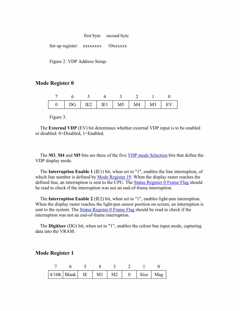
first byte second byte
Set up register: xxxxxxxx 10xxxxxx
Figure 2: VDP Address Setup.
Mode Register 0
7 6 5 4 3 2 1 0
0 DG IE2 IE1 M5 M4 M3 EV
Figure 3.
The External VDP (EV) bit determines whether external VDP input is to be enabled or disabled: 0=Disabled, 1=Enabled.
The M3, M4 and M5 bits are three of the five VDP mode Selection bits that define the VDP display mode.
The Interruption Enable 1 (IE1) bit, when set to "1", enables the line interruption, of which line number is defined by Mode Register 19. When the display raster reaches the defined line, an interruption is sent to the CPU. The Status Register 0 Frame Flag should be read to check if the interruption was not an end-of-frame interruption.
The Interruption Enable 2 (IE2) bit, when set to "1", enables light-pen interruption. When the display raster reaches the light-pen sensor position on screen, an interruption is sent to the system. The Status Register 0 Frame Flag should be read to check if the interruption was not an end-of-frame interruption.
The Digitizer (DG) bit, when set to "1", enables the colour bus input mode, capturing data into the VRAM.
Mode Register 1
7 6 5 4 3 2 1 0
4/16K Blank IE M1 M2 0 Size Mag
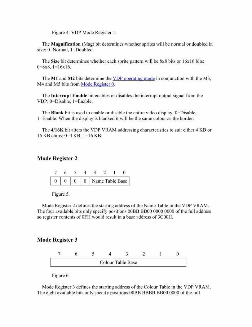
Figure 4: VDP Mode Register 1.
The Magnification (Mag) bit determines whether sprites will be normal or doubled in size: 0=Normal, 1=Doubled.
The Size bit determines whether each sprite pattern will be 8x8 bits or 16x16 bits: 0=8x8, 1=16x16.
The M1 and M2 bits determine the VDP operating mode in conjunction with the M3, M4 and M5 bits from Mode Register 0.
The Interrupt Enable bit enables or disables the interrupt output signal from the VDP: 0=Disable, 1=Enable.
The Blank bit is used to enable or disable the entire video display: 0=Disable, 1=Enable. When the display is blanked it will be the same colour as the border.
The 4/16K bit alters the VDP VRAM addressing characteristics to suit either 4 KB or 16 KB chips: 0=4 KB, 1=16 KB.
Mode Register 2
7 6 5 4 3 2 1 0
0 0 0 0 Name Table Base
Figure 5.
Mode Register 2 defines the starting address of the Name Table in the VDP VRAM. The four available bits only specify positions 00BB BB00 0000 0000 of the full address so register contents of 0FH would result in a base address of 3C00H.
Mode Register 3
7 6 5 4 3 2 1 0
Colour Table Base
Figure 6.
Mode Register 3 defines the starting address of the Colour Table in the VDP VRAM. The eight available bits only specify positions 00BB BBBB BB00 0000 of the full
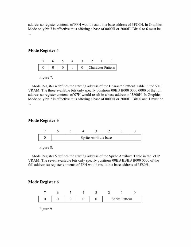
address so register contents of FFH would result in a base address of 3FC0H. In Graphics Mode only bit 7 is effective thus offering a base of 0000H or 2000H. Bits 0 to 6 must be 1.
Mode Register 4
7 6 5 4 3 2 1 0
0 0 0 0 0 Character Pattern
Figure 7.
Mode Register 4 defines the starting address of the Character Pattern Table in the VDP VRAM. The three available bits only specify positions 00BB B000 0000 0000 of the full address so register contents of 07H would result in a base address of 3800H. In Graphics Mode only bit 2 is effective thus offering a base of 0000H or 2000H. Bits 0 and 1 must be 1.
Mode Register 5
7 6 5 4 3 2 1 0
0 Sprite Attribute base
Figure 8.
Mode Register 5 defines the starting address of the Sprite Attribute Table in the VDP VRAM. The seven available bits only specify positions 00BB BBBB B000 0000 of the full address so register contents of 7FH would result in a base address of 3F80H.
Mode Register 6
7 6 5 4 3 2 1 0
0 0 0 0 0 Sprite Pattern
Figure 9.

Mode Register 6 defines the starting address of the Sprite Pattern Table in the VDP VRAM. The three available bits only specify positions 00BB B000 0000 0000 of the full address so register contents of 07H would result in a base address of 3800H.
Mode Register 7
7 6 5 4 3 2 1 0
Text Colour 1 Border Colour
Figure 10.
The Border Colour bits determine the colour of the region surrounding the active video area in all four VDP modes. They also determine the colour of all 0 pixels on the screen in 40x24 Text Mode. Note that the border region actually extends across the entire screen but will only become visible in the active area if the overlying pixel is transparent.
The Text Colour 1 bits determine the colour of all 1 pixels in 40x24 Text Mode. They have no effect in the other three modes where greater flexibility is provided through the use of the Colour Table. The VDP colour codes are:
Index Colour Name
0 Transparent
1 Black
2 Green
3 Light Green
4 Dark Blue
5 Light Blue
6 Dark Red
7 Cyan
8 Red
9 Bright Red
10 Yellow
11 Light Yellow
12 Dark Green
13
Purple
14 Gray
15 White
Figure 11: MSX default colours.
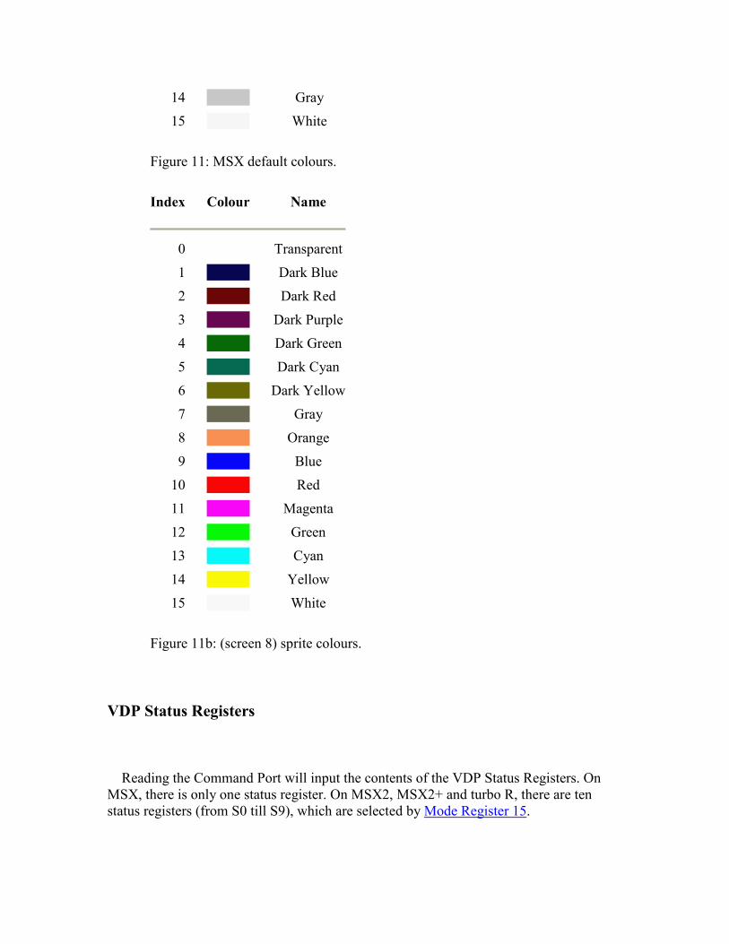
Index Colour Name
0 Transparent
1 Dark Blue
2 Dark Red
3 Dark Purple
4 Dark Green
5 Dark Cyan
6 Dark Yellow
7 Gray
8 Orange
9 Blue
10 Red
11 Magenta
12 Green
13 Cyan
14 Yellow
15
White
Figure 11b: (screen 8) sprite colours.
VDP Status Registers
Reading the Command Port will input the contents of the VDP Status Registers. On MSX, there is only one status register. On MSX2, MSX2+ and turbo R, there are ten status registers (from S0 till S9), which are selected by Mode Register 15.
VDP Status Register 0
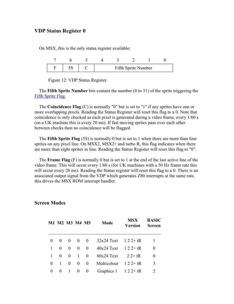
On MSX, this is the only status register available:
7 6 5 4 3 2 1 0
F 5S C Fifth Sprite Number
Figure 12: VDP Status Register.
The Fifth Sprite Number bits contain the number (0 to 31) of the sprite triggering the Fifth Sprite Flag.
The Coincidence Flag (C) is normally "0" but is set to "1" if any sprites have one or more overlapping pixels. Reading the Status Register will reset this flag to a 0. Note that coincidence is only checked as each pixel is generated during a video frame, every 1/60 s (on a UK machine this is every 20 ms). If fast moving sprites pass over each other between checks then no coincidence will be flagged.
The Fifth Sprite Flag (5S) is normally 0 but is set to 1 when there are more than four sprites on any pixel line. On MSX2, MSX2+ and turbo R, this flag indicates when there are more than eight sprites in line. Reading the Status Register will reset this flag to "0".
The Frame Flag (F) is normally 0 but is set to 1 at the end of the last active line of the video frame. This will occur every 1/60 s (for UK machines with a 50 Hz frame rate this will occur every 20 ms). Reading the Status register will reset this flag to a 0. There is an associated output signal from the VDP which generates Z80 interrupts at the same rate, this drives the MSX ROM interrupt handler.
Screen Modes
M1 M2 M3 M4 M5 Mode MSX
Version BASIC
Screen
0 0 0 0 0 32x24 Text 1 2 2+ tR 1
1 0 0 0 0 40x24 Text 1 2 2+ tR 0
1 0 0 1 0 80x24 Text 2 2+ tR 0
0 1 0 0 0 Multicolour 1 2 2+ tR 3
0 0 1 0 0
Graphics 1
1 2 2+ tR
2
0 0 0 1 0 Graphics 2 2 2+ tR 4
0 0 1 1 0 Graphics 4 2 2+ tR 5
0 0 0 0 1 Graphics 5 2 2+ tR 6
0 0 1 0 1 Graphics 6 2 2+ tR 7
0 0 1 1 1 Graphics 7 2 2+ tR 8
The VDP has thirteen operating modes, each one offering a slightly different set of capabilities. Generally speaking, as the resolution goes up the price to be paid in VRAM size and updating complexity also increases. In a dedicated application these associated hardware and software costs are important considerations. For an MSX machine they are irrelevant, it therefore seems a pity that a greater attempt was not made to standardize on one particular mode. The Graphics Mode is capable of adequately performing all the functions of the other modes with only minor reservations.
An added difficulty in using the VDP arises because insufficient allowance was made in its design for the overscanning used by most televisions. The resulting loss of characters at the screen edges has forced all the video-related MSX software into being based on peculiar screen sizes. UK machines normally use only the central thirty-seven characters available in 40x24 Text Mode. Japanese machines, with NTSC (National Television Standards Committee) video outputs, use the central thirty-nine characters.
The central element in the VDP, from the programmer's point of view, is the Name Table. This is a simple list of single- byte character codes held in VRAM. It is 960 bytes long in 40x24 Text Mode, 768 bytes long in 32x24 Text Mode, Graphics Mode and Multicolour Mode. Each position in the Name Table corresponds to a particular location on the screen.
During a video frame the VDP will sequentially read every character code from the Name Table, starting at the base. As each character code is read the corresponding 8x8 pattern of pixels is looked up in the Character Pattern Table and displayed on the screen. The appearance of the screen can thus be modified by either changing the character codes in the Name Table or the pixel patterns in the Character Pattern Table.
Note that the VDP has no hardware cursor facility, if one is required it must be software generated.
40x24 Text Mode
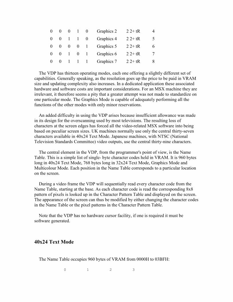
The Name Table occupies 960 bytes of VRAM from 0000H to 03BFH:
0 1 2 3
0123456789012345678901234567890123456789 0000H OOOOOOOOOOOOOOOOOOOOOOOOOOOOOOOOOOOOOOOO 00028H OOOOOOOOOOOOOOOOOOOOOOOOOOOOOOOOOOOOOOOO 10050H OOOOOOOOOOOOOOOOOOOOOOOOOOOOOOOOOOOOOOOO 20078H OOOOOOOOOOOOOOOOOOOOOOOOOOOOOOOOOOOOOOOO 3
00A0H
OOOOOOOOOOOOOOOOOOOOOOOOOOOOOOOOOOOOOOOO 4
00C8H OOOOOOOOOOOOOOOOOOOOOOOOOOOOOOOOOOOOOOOO 500F0H OOOOOOOOOOOOOOOOOOOOOOOOOOOOOOOOOOOOOOOO 60118H OOOOOOOOOOOOOOOOOOOOOOOOOOOOOOOOOOOOOOOO 70140H OOOOOOOOOOOOOOOOOOOOOOOOOOOOOOOOOOOOOOOO 80168H OOOOOOOOOOOOOOOOOOOOOOOOOOOOOOOOOOOOOOOO 9
0190H OOOOOOOOOOOOOOOOOOOOOOOOOOOOOOOOOOOOOOOO 10
01B8H OOOOOOOOOOOOOOOOOOOOOOOOOOOOOOOOOOOOOOOO 11
01E0H OOOOOOOOOOOOOOOOOOOOOOOOOOOOOOOOOOOOOOOO 12
0208H OOOOOOOOOOOOOOOOOOOOOOOOOOOOOOOOOOOOOOOO 13
0230H OOOOOOOOOOOOOOOOOOOOOOOOOOOOOOOOOOOOOOOO 14
0258H OOOOOOOOOOOOOOOOOOOOOOOOOOOOOOOOOOOOOOOO 15
0280H OOOOOOOOOOOOOOOOOOOOOOOOOOOOOOOOOOOOOOOO 16
02A8H
OOOOOOOOOOOOOOOOOOOOOOOOOOOOOOOOOOOOOOOO 17
02D0H
OOOOOOOOOOOOOOOOOOOOOOOOOOOOOOOOOOOOOOOO 18
02F8H OOOOOOOOOOOOOOOOOOOOOOOOOOOOOOOOOOOOOOOO 19
0320H OOOOOOOOOOOOOOOOOOOOOOOOOOOOOOOOOOOOOOOO 20
0348H OOOOOOOOOOOOOOOOOOOOOOOOOOOOOOOOOOOOOOOO 21
0370H OOOOOOOOOOOOOOOOOOOOOOOOOOOOOOOOOOOOOOOO 22
0398H OOOOOOOOOOOOOOOOOOOOOOOOOOOOOOOOOOOOOOOO 23
0123456789012345678901234567890123456789 0 1 2 3
Figure 25: 40x24 Name Table.
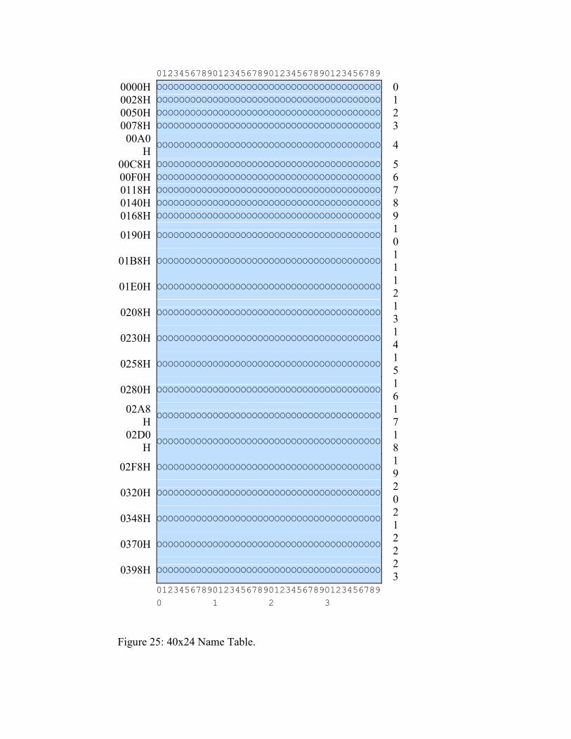
Pattern Table occupies 2 KB of VRAM from 0800H to 0FFFH. Each eight byte block contains the pixel pattern for a character code:
0 0 1 0 0 0 0 0
Byte 0
0 1 0 1 0 0 0 0
Byte 1
1 0 0 0 1 0 0 0
Byte 2
1 0 0 0 1 0 0 0
Byte 3
1 1 1 1 1 0 0 0
Byte 4
1 0 0 0 1 0 0 0
Byte 5
1 0 0 0 1 0 0 0
Byte 6
0 0 0 0 0 0 0 0
Byte 7
Figure 26: Character Pattern Block (No. 65 shown = 'A').
The first block contains the pattern for character code 0, the second the pattern for character code 1 and so on to character code 255. Note that only the leftmost six pixels are actually displayed in this mode. The colours of the 0 and 1 pixels in this mode are defined by VDP Mode Register 7, initially they are blue and white (on Japanese and European machines) or black and white (on Brazilian machines).
32x24 Text Mode
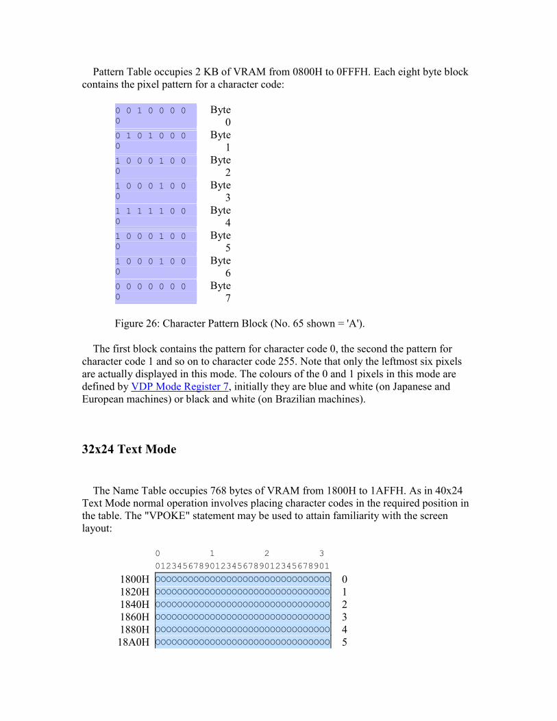
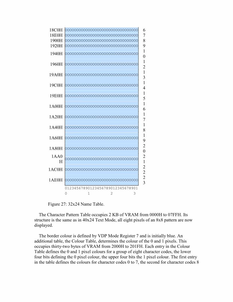
The Name Table occupies 768 bytes of VRAM from 1800H to 1AFFH. As in 40x24 Text Mode normal operation involves placing character codes in the required position in the table. The "VPOKE" statement may be used to attain familiarity with the screen layout:
0 1 2 3 01234567890123456789012345678901 1800H OOOOOOOOOOOOOOOOOOOOOOOOOOOOOOOO 01820H OOOOOOOOOOOOOOOOOOOOOOOOOOOOOOOO 11840H OOOOOOOOOOOOOOOOOOOOOOOOOOOOOOOO 21860H OOOOOOOOOOOOOOOOOOOOOOOOOOOOOOOO 31880H OOOOOOOOOOOOOOOOOOOOOOOOOOOOOOOO 418A0H
OOOOOOOOOOOOOOOOOOOOOOOOOOOOOOOO
5
18C0H OOOOOOOOOOOOOOOOOOOOOOOOOOOOOOOO 618E0H OOOOOOOOOOOOOOOOOOOOOOOOOOOOOOOO 71900H OOOOOOOOOOOOOOOOOOOOOOOOOOOOOOOO 81920H OOOOOOOOOOOOOOOOOOOOOOOOOOOOOOOO 9
1940H OOOOOOOOOOOOOOOOOOOOOOOOOOOOOOOO 10
1960H OOOOOOOOOOOOOOOOOOOOOOOOOOOOOOOO 12
19A0H OOOOOOOOOOOOOOOOOOOOOOOOOOOOOOOO 13
19C0H OOOOOOOOOOOOOOOOOOOOOOOOOOOOOOOO 14
19E0H OOOOOOOOOOOOOOOOOOOOOOOOOOOOOOOO 15
1A00H OOOOOOOOOOOOOOOOOOOOOOOOOOOOOOOO 16
1A20H OOOOOOOOOOOOOOOOOOOOOOOOOOOOOOOO 17
1A40H OOOOOOOOOOOOOOOOOOOOOOOOOOOOOOOO 18
1A60H OOOOOOOOOOOOOOOOOOOOOOOOOOOOOOOO 19
1A80H OOOOOOOOOOOOOOOOOOOOOOOOOOOOOOOO 20
1AA0H
OOOOOOOOOOOOOOOOOOOOOOOOOOOOOOOO 21
1AC0H OOOOOOOOOOOOOOOOOOOOOOOOOOOOOOOO 22
1AE0H OOOOOOOOOOOOOOOOOOOOOOOOOOOOOOOO 23
01234567890123456789012345678901 0 1 2 3
Figure 27: 32x24 Name Table.
The Character Pattern Table occupies 2 KB of VRAM from 0000H to 07FFH. Its structure is the same as in 40x24 Text Mode, all eight pixels of an 8x8 pattern are now displayed.
The border colour is defined by VDP Mode Register 7 and is initially blue. An additional table, the Colour Table, determines the colour of the 0 and 1 pixels. This occupies thirty-two bytes of VRAM from 2000H to 201FH. Each entry in the Colour Table defines the 0 and 1 pixel colours for a group of eight character codes, the lower four bits defining the 0 pixel colour, the upper four bits the 1 pixel colour. The first entry in the table defines the colours for character codes 0 to 7, the second for character codes 8
to 15 and so on for thirty-two entries. The MSX ROM initializes all entries to the same value, blue and white, and provides no facilities for changing individual ones.
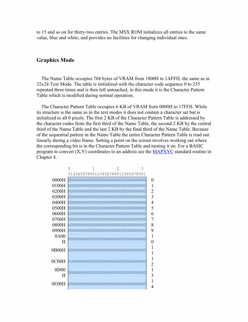
Graphics Mode
The Name Table occupies 768 bytes of VRAM from 1800H to 1AFFH, the same as in 32x24 Text Mode. The table is initialized with the character code sequence 0 to 255 repeated three times and is then left untouched, in this mode it is the Character Pattern Table which is modified during normal operation.
The Character Pattern Table occupies 6 KB of VRAM from 0000H to 17FFH. While its structure is the same as in the text modes it does not contain a character set but is initialized to all 0 pixels. The first 2 KB of the Character Pattern Table is addressed by the character codes from the first third of the Name Table, the second 2 KB by the central third of the Name Table and the last 2 KB by the final third of the Name Table. Because of the sequential pattern in the Name Table the entire Character Pattern Table is read out linearly during a video frame. Setting a point on the screen involves working out where the corresponding bit is in the Character Pattern Table and turning it on. For a BASIC program to convert (X,Y) coordinates to an address see the MAPXYC standard routine in Chapter 4.
0 1 2 3 01234567890123456789012345678901 0000H OOOOOOOOOOOOOOOOOOOOOOOOOOOOOOOO 00100H OOOOOOOOOOOOOOOOOOOOOOOOOOOOOOOO 10200H OOOOOOOOOOOOOOOOOOOOOOOOOOOOOOOO 20300H OOOOOOOOOOOOOOOOOOOOOOOOOOOOOOOO 30400H OOOOOOOOOOOOOOOOOOOOOOOOOOOOOOOO 40500H OOOOOOOOOOOOOOOOOOOOOOOOOOOOOOOO 50600H OOOOOOOOOOOOOOOOOOOOOOOOOOOOOOOO 60700H OOOOOOOOOOOOOOOOOOOOOOOOOOOOOOOO 70800H OOOOOOOOOOOOOOOOOOOOOOOOOOOOOOOO 80900H OOOOOOOOOOOOOOOOOOOOOOOOOOOOOOOO 9
0A00H
OOOOOOOOOOOOOOOOOOOOOOOOOOOOOOOO 10
0B00H OOOOOOOOOOOOOOOOOOOOOOOOOOOOOOOO 11
0C00H OOOOOOOOOOOOOOOOOOOOOOOOOOOOOOOO 12
0D00H
OOOOOOOOOOOOOOOOOOOOOOOOOOOOOOOO 13
0E00H
OOOOOOOOOOOOOOOOOOOOOOOOOOOOOOOO
14
0F00H OOOOOOOOOOOOOOOOOOOOOOOOOOOOOOOO 15
1000H OOOOOOOOOOOOOOOOOOOOOOOOOOOOOOOO 16
1100H OOOOOOOOOOOOOOOOOOOOOOOOOOOOOOOO 17
1200H OOOOOOOOOOOOOOOOOOOOOOOOOOOOOOOO 18
1300H OOOOOOOOOOOOOOOOOOOOOOOOOOOOOOOO 19
1400H OOOOOOOOOOOOOOOOOOOOOOOOOOOOOOOO 20
1500H OOOOOOOOOOOOOOOOOOOOOOOOOOOOOOOO 21
1600H OOOOOOOOOOOOOOOOOOOOOOOOOOOOOOOO 22
1700H OOOOOOOOOOOOOOOOOOOOOOOOOOOOOOOO 23
01234567890123456789012345678901 0 1 2 3
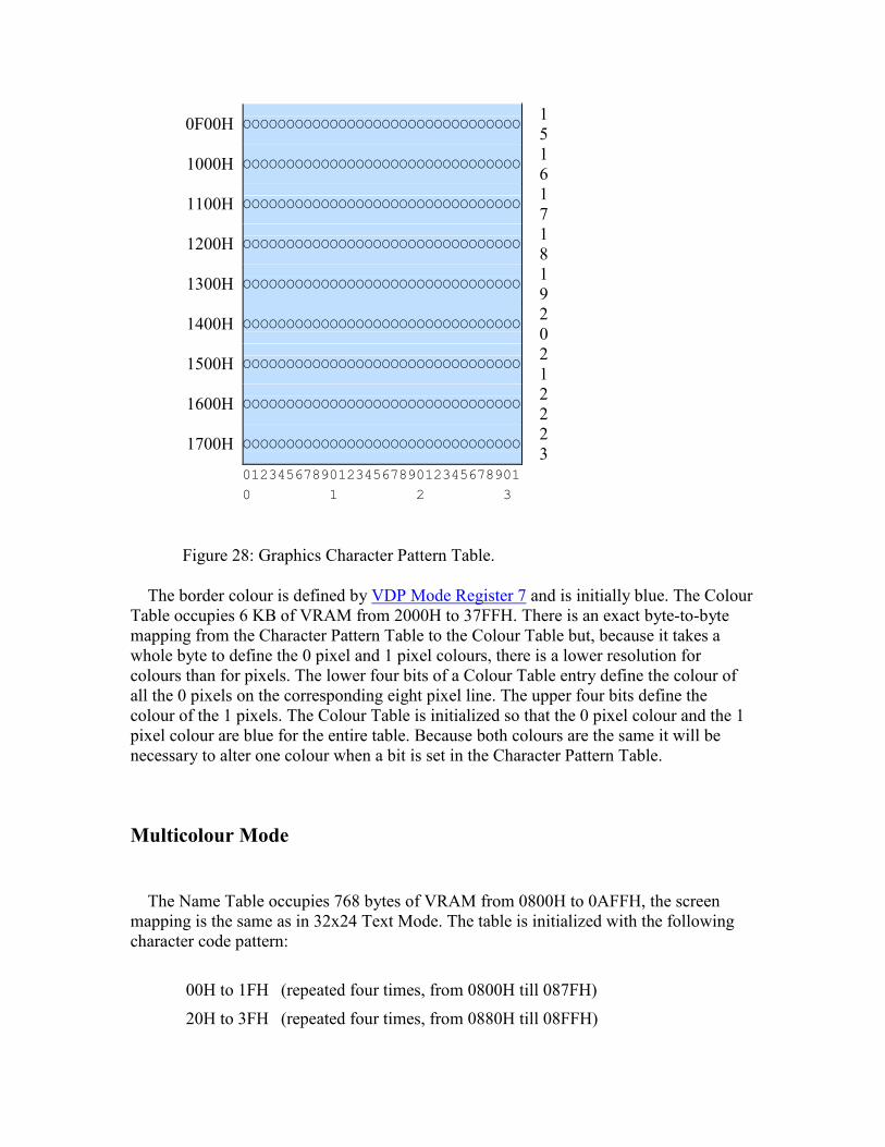
Figure 28: Graphics Character Pattern Table.
The border colour is defined by VDP Mode Register 7 and is initially blue. The Colour Table occupies 6 KB of VRAM from 2000H to 37FFH. There is an exact byte-to-byte mapping from the Character Pattern Table to the Colour Table but, because it takes a whole byte to define the 0 pixel and 1 pixel colours, there is a lower resolution for colours than for pixels. The lower four bits of a Colour Table entry define the colour of all the 0 pixels on the corresponding eight pixel line. The upper four bits define the colour of the 1 pixels. The Colour Table is initialized so that the 0 pixel colour and the 1 pixel colour are blue for the entire table. Because both colours are the same it will be necessary to alter one colour when a bit is set in the Character Pattern Table.
Multicolour Mode
The Name Table occupies 768 bytes of VRAM from 0800H to 0AFFH, the screen mapping is the same as in 32x24 Text Mode. The table is initialized with the following character code pattern:
00H to 1FH (repeated four times, from 0800H till 087FH)
20H to 3FH (repeated four times, from 0880H till 08FFH)
40H to 5FH (repeated four times, from 0900H till 097FH)
60H to 7FH (repeated four times, from 0980H till 09FFH)
80H to 9FH (repeated four times, from 0A00H till 0A7FH)
A0H to BFH (repeated four times, from 0A80H till 0AFFH)
As with Graphics Mode this is just a character code "driver" pattern, it is the Character Pattern Table which is modified during normal operation.
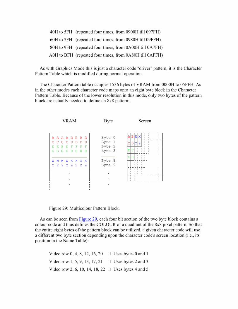
The Character Pattern table occupies 1536 bytes of VRAM from 0000H to 05FFH. As in the other modes each character code maps onto an eight byte block in the Character Pattern Table. Because of the lower resolution in this mode, only two bytes of the pattern block are actually needed to define an 8x8 pattern:
VRAM Byte Screen
A A A A B B B B C C C C D D D D E E E E F F F F G G G G H H H H
W W W W X X X X Y Y Y Y Z Z Z Z
.
.
.
Byte 0 Byte 1 Byte 2 Byte 3
Byte 8 Byte 9
.
.
.
A B W X C D Y Z E F G H
Figure 29: Multicolour Pattern Block.
As can be seen from Figure 29, each four bit section of the two byte block contains a colour code and thus defines the COLOUR of a quadrant of the 8x8 pixel pattern. So that the entire eight bytes of the pattern block can be utilized, a given character code will use a different two byte section depending upon the character code's screen location (i.e., its position in the Name Table):
Video row 0, 4, 8, 12, 16, 20 ⇒ Uses bytes 0 and 1
Video row 1, 5, 9, 13, 17, 21 ⇒ Uses bytes 2 and 3
Video row 2, 6, 10, 14, 18, 22 ⇒ Uses bytes 4 and 5

Video row 3, 7, 11, 15, 19, 23 ⇒ Uses bytes 6 and 7
When the Name Table is filled with the special driver sequence of character codes shown above the Character Pattern Table will be read out linearly during a video frame:
0 1 2 3 01234567890123456789012345678901
0000H
OOOOOOOOOOOOOOOOOOOOOOOOOOOOOOOO 0
0002H
OOOOOOOOOOOOOOOOOOOOOOOOOOOOOOOO 1
0004H
OOOOOOOOOOOOOOOOOOOOOOOOOOOOOOOO 2
0006H
OOOOOOOOOOOOOOOOOOOOOOOOOOOOOOOO 3
0100H
OOOOOOOOOOOOOOOOOOOOOOOOOOOOOOOO 4
0102H
OOOOOOOOOOOOOOOOOOOOOOOOOOOOOOOO 5
0104H
OOOOOOOOOOOOOOOOOOOOOOOOOOOOOOOO 6
0106H
OOOOOOOOOOOOOOOOOOOOOOOOOOOOOOOO 7
0200H
OOOOOOOOOOOOOOOOOOOOOOOOOOOOOOOO 8
0202H
OOOOOOOOOOOOOOOOOOOOOOOOOOOOOOOO 9
0204H
OOOOOOOOOOOOOOOOOOOOOOOOOOOOOOOO 10
0206H
OOOOOOOOOOOOOOOOOOOOOOOOOOOOOOOO 11
0300H
OOOOOOOOOOOOOOOOOOOOOOOOOOOOOOOO 12
0302H
OOOOOOOOOOOOOOOOOOOOOOOOOOOOOOOO 13
0304H
OOOOOOOOOOOOOOOOOOOOOOOOOOOOOOOO 14
0306H
OOOOOOOOOOOOOOOOOOOOOOOOOOOOOOOO 15
0400H
OOOOOOOOOOOOOOOOOOOOOOOOOOOOOOOO 16
0402H
OOOOOOOOOOOOOOOOOOOOOOOOOOOOOOOO 17
0404H
OOOOOOOOOOOOOOOOOOOOOOOOOOOOOOOO 18
0406
OOOOOOOOOOOOOOOOOOOOOOOOOOOOOOOO
1
H 90500
HOOOOOOOOOOOOOOOOOOOOOOOOOOOOOOOO 2
00502
HOOOOOOOOOOOOOOOOOOOOOOOOOOOOOOOO 2
10504
HOOOOOOOOOOOOOOOOOOOOOOOOOOOOOOOO 2
20506
HOOOOOOOOOOOOOOOOOOOOOOOOOOOOOOOO 2
3 01234567890123456789012345678901 0 1 2 3
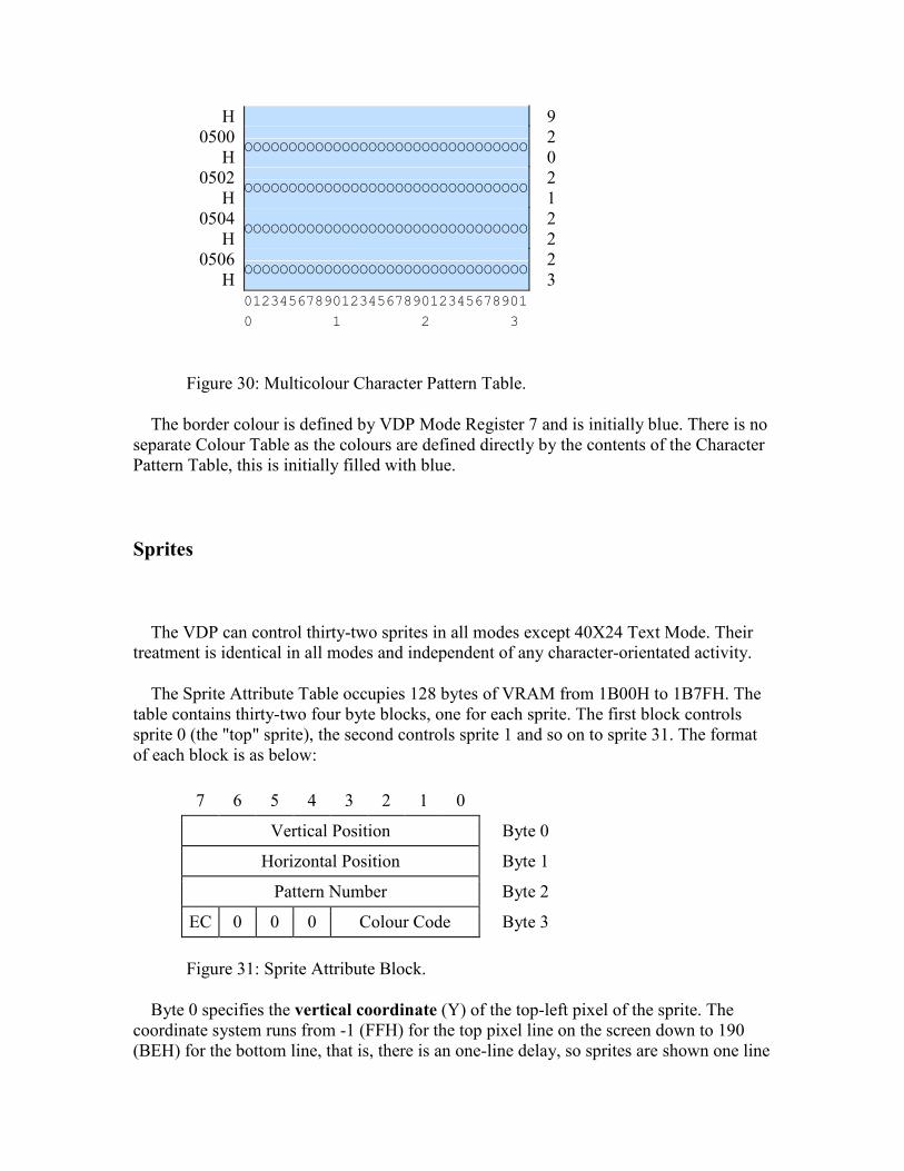
Figure 30: Multicolour Character Pattern Table.
The border colour is defined by VDP Mode Register 7 and is initially blue. There is no separate Colour Table as the colours are defined directly by the contents of the Character Pattern Table, this is initially filled with blue.
Sprites
The VDP can control thirty-two sprites in all modes except 40X24 Text Mode. Their treatment is identical in all modes and independent of any character-orientated activity.
The Sprite Attribute Table occupies 128 bytes of VRAM from 1B00H to 1B7FH. The table contains thirty-two four byte blocks, one for each sprite. The first block controls sprite 0 (the "top" sprite), the second controls sprite 1 and so on to sprite 31. The format of each block is as below:
7 6 5 4 3 2 1 0
Vertical Position Byte 0
Horizontal Position Byte 1
Pattern Number Byte 2
EC 0 0 0 Colour Code
Byte 3
Figure 31: Sprite Attribute Block.
Byte 0 specifies the vertical coordinate (Y) of the top-left pixel of the sprite. The coordinate system runs from -1 (FFH) for the top pixel line on the screen down to 190 (BEH) for the bottom line, that is, there is an one-line delay, so sprites are shown one line
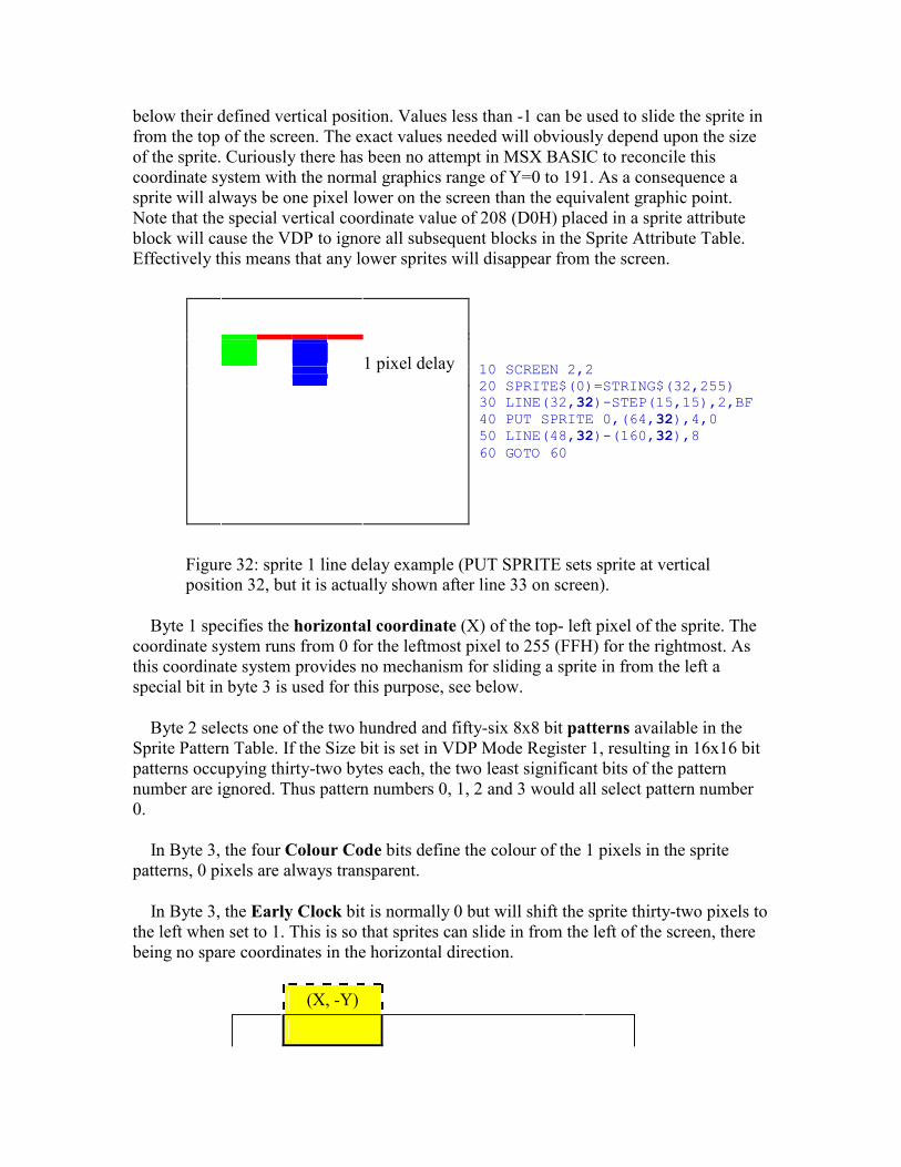
below their defined vertical position. Values less than -1 can be used to slide the sprite in from the top of the screen. The exact values needed will obviously depend upon the size of the sprite. Curiously there has been no attempt in MSX BASIC to reconcile this coordinate system with the normal graphics range of Y=0 to 191. As a consequence a sprite will always be one pixel lower on the screen than the equivalent graphic point. Note that the special vertical coordinate value of 208 (D0H) placed in a sprite attribute block will cause the VDP to ignore all subsequent blocks in the Sprite Attribute Table. Effectively this means that any lower sprites will disappear from the screen.
1 pixel delay
10 SCREEN 2,2 20 SPRITE$(0)=STRING$(32,255) 30 LINE(32,32)-STEP(15,15),2,BF40 PUT SPRITE 0,(64,32),4,0 50 LINE(48,32)-(160,32),8 60 GOTO 60
Figure 32: sprite 1 line delay example (PUT SPRITE sets sprite at vertical position 32, but it is actually shown after line 33 on screen).
Byte 1 specifies the horizontal coordinate (X) of the top- left pixel of the sprite. The coordinate system runs from 0 for the leftmost pixel to 255 (FFH) for the rightmost. As this coordinate system provides no mechanism for sliding a sprite in from the left a special bit in byte 3 is used for this purpose, see below.
Byte 2 selects one of the two hundred and fifty-six 8x8 bit patterns available in the Sprite Pattern Table. If the Size bit is set in VDP Mode Register 1, resulting in 16x16 bit patterns occupying thirty-two bytes each, the two least significant bits of the pattern number are ignored. Thus pattern numbers 0, 1, 2 and 3 would all select pattern number 0.
In Byte 3, the four Colour Code bits define the colour of the 1 pixels in the sprite patterns, 0 pixels are always transparent.
In Byte 3, the Early Clock bit is normally 0 but will shift the sprite thirty-two pixels to the left when set to 1. This is so that sprites can slide in from the left of the screen, there being no spare coordinates in the horizontal direction.
(X, -Y)
(X, Y)
(X-32, Y) ⇐ EC=1
← (X-32, Y)
⇐ EC=1 (X, Y) →
(X, Y)
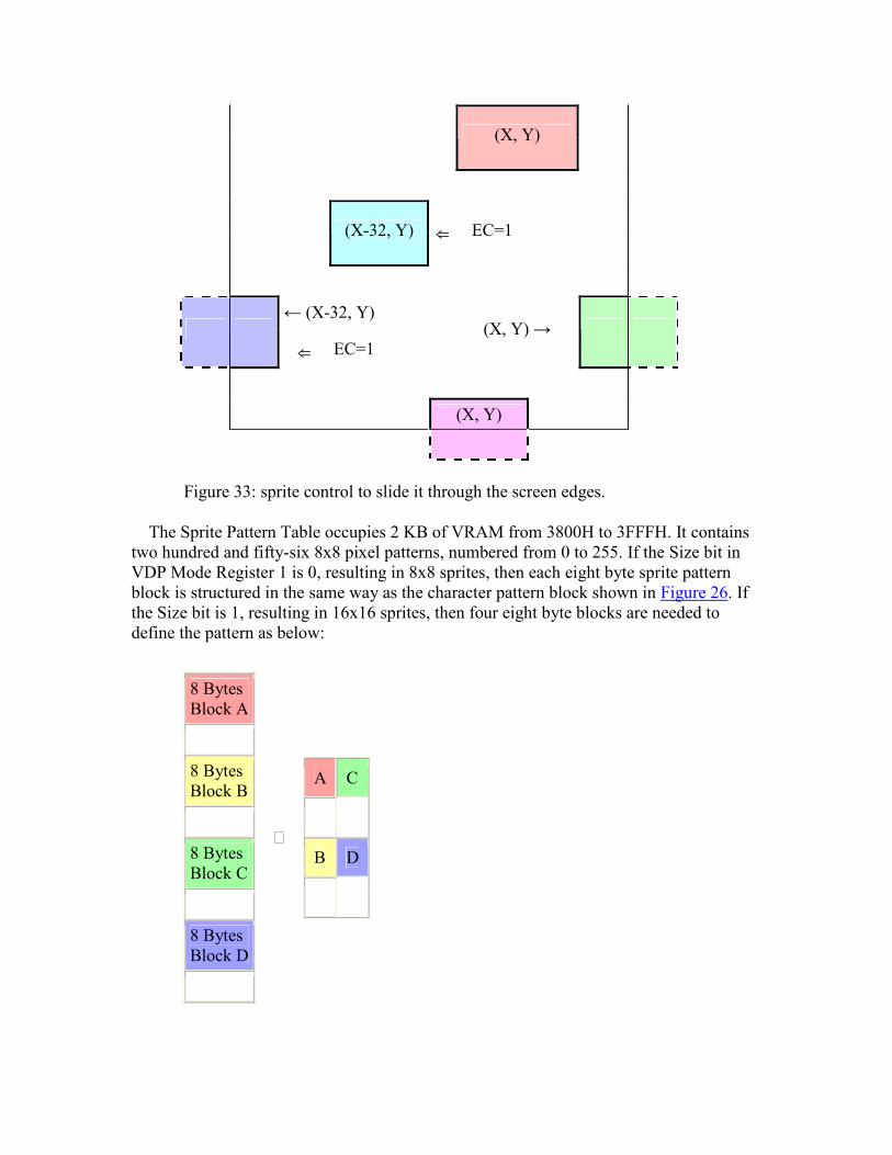
Figure 33: sprite control to slide it through the screen edges.
The Sprite Pattern Table occupies 2 KB of VRAM from 3800H to 3FFFH. It contains two hundred and fifty-six 8x8 pixel patterns, numbered from 0 to 255. If the Size bit in VDP Mode Register 1 is 0, resulting in 8x8 sprites, then each eight byte sprite pattern block is structured in the same way as the character pattern block shown in Figure 26. If the Size bit is 1, resulting in 16x16 sprites, then four eight byte blocks are needed to define the pattern as below:
8 Bytes Block A
8 Bytes Block B
8 Bytes Block C
8 Bytes Block D
⇒
A C
B D
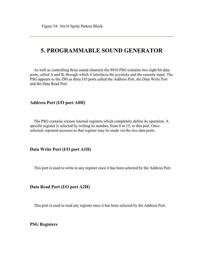
Figure 34: 16x16 Sprite Pattern Block.
5. PROGRAMMABLE SOUND GENERATOR
As well as controlling three sound channels the 8910 PSG contains two eight bit data ports, called A and B, through which it interfaces the joysticks and the cassette input. The PSG appears to the Z80 as three I/O ports called the Address Port, the Data Write Port and the Data Read Port.
Address Port (I/O port A0H)
The PSG contains sixteen internal registers which completely define its operation. A specific register is selected by writing its number, from 0 to 15, to this port. Once selected, repeated accesses to that register may be made via the two data ports.
Data Write Port (I/O port A1H)
This port is used to write to any register once it has been selected by the Address Port.
Data Read Port (I/O port A2H)
This port is used to read any register once it has been selected by the Address Port.
PSG Registers
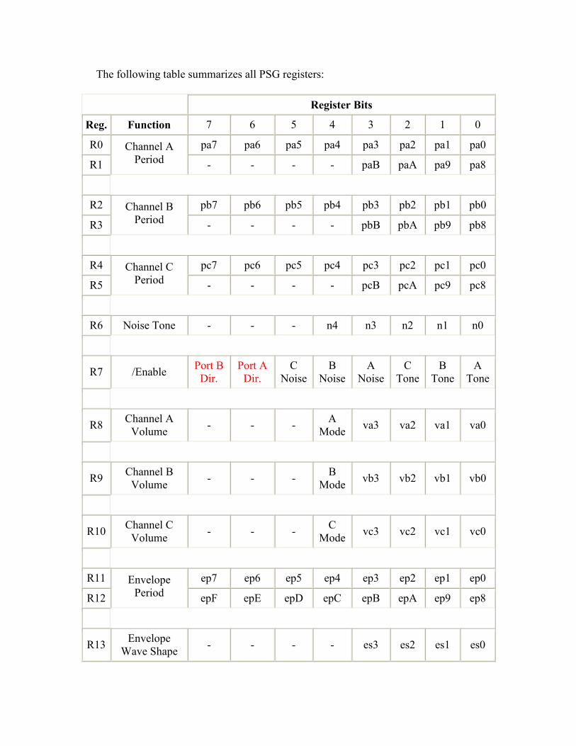
The following table summarizes all PSG registers:
Register Bits
Reg. Function 7 6 5 4 3 2 1 0
R0 pa7 pa6 pa5 pa4 pa3 pa2 pa1 pa0
R1
Channel A Period - - - - paB paA pa9 pa8
R2 pb7 pb6 pb5 pb4 pb3 pb2 pb1 pb0
R3
Channel B Period - - - - pbB pbA pb9 pb8
R4 pc7 pc6 pc5 pc4 pc3 pc2 pc1 pc0
R5
Channel C Period - - - - pcB pcA pc9 pc8
R6 Noise Tone - - - n4 n3 n2 n1 n0
R7 /Enable Port B Dir.
Port A Dir.
C Noise
B Noise
A Noise
C Tone
B Tone
A Tone
R8 Channel A Volume - - - A
Mode va3 va2 va1 va0
R9 Channel B Volume - - - B
Mode vb3 vb2 vb1 vb0
R10 Channel C Volume - - - C
Mode vc3 vc2 vc1 vc0
R11 ep7 ep6 ep5 ep4 ep3 ep2 ep1 ep0
R12
Envelope Period epF epE epD epC epB epA ep9 ep8
R13 Envelope Wave Shape - - - - es3 es2 es1 es0

R14 I/O Port A Cas Input
Kbd Mode
Joy Trg.B
Joy Trg.A
Joy Right
Joy Left
Joy Back
Joy Fwd
R15 I/O Port B Kana LED
Joy Sel
Pulse 2
Pulse 1 1 1 1 1
Important note: the PSG registers R14 and R15 can be programmed for input or output. On MSX, R14 must be ever programmed for input and, R15, for output. Thus, bit 6 of R7 must ever be set to "0" (input) and, bit 7, to "1" (output). Programming them otherwise may cause severe damage to the machine, putting active coupling circuitry connected to R14 and R15 in short-circuit. More details on PSG register 7 section.
PSG Registers 0 and 1
7 6 5 4 3 2 1 0
Channel A Frequency (LSB) R0
x x x x Channel A Frequency (MSB)
R1
Figure 2: channel A period control registers.
These two registers are used to define the frequency of the Tone Generator for Channel A. Variable frequencies are produced by dividing a fixed master frequency with the number held in Registers 0 and 1, this number can be in the range 1 to 4095. Register 0 holds the least significant eight bits and Register 1 the most significant four. The PSG divides an external 1.7897725 MHz frequency by sixteen to produce a Tone Generator master frequency of 111,861 Hz. The output of the Tone Generator can therefore range from 111,861 Hz (divide by 1) down to 27.3 Hz (divide by 4095). As an example to produce a middle "A" (440 Hz) the divider value in Registers 0 and 1 would be 254.
PSG Registers 2 and 3
7 6 5 4 3 2 1 0
Channel B Frequency (LSB) R2
x x x x Channel B Frequency
R3
(MSB)
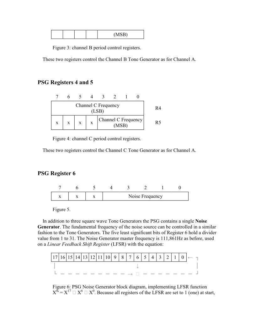
Figure 3: channel B period control registers.
These two registers control the Channel B Tone Generator as for Channel A.
PSG Registers 4 and 5
7 6 5 4 3 2 1 0
Channel C Frequency (LSB) R4
x x x x Channel C Frequency (MSB)
R5
Figure 4: channel C period control registers.
These two registers control the Channel C Tone Generator as for Channel A.
PSG Register 6
7 6 5 4 3 2 1 0
x x x Noise Frequency
Figure 5.
In addition to three square wave Tone Generators the PSG contains a single Noise
Generator. The fundamental frequency of the noise source can be controlled in a similar fashion to the Tone Generators. The five least significant bits of Register 6 hold a divider value from 1 to 31. The Noise Generator master frequency is 111,861Hz as before, used on a Linear Feedback Shift Register (LFSR) with the equation:
17 16 15 14 13 12 11 10 9 8 7 6 5 4 3 2 1 0 ← ┐
│ ↓ │
└ ─ ─ ─ ─ ─ ─ ─ ─ ─ → ⇒ ─ ─ ─ ─ ─ ─ ─ ┘
Figure 6: PSG Noise Generator block diagram, implementing LFSR function X0' = X17 ⇒ X6 ⇒ X0. Because all registers of the LFSR are set to 1 (one) at start,

the X0 term is supressed (X0 = 1, so it would just invert the state of X0', and once all registers are already inverted at start, it must be removed to assure an initial zero to the pseudo-random sequence). The noise output is extracted from register 0.
PSG Register 7
7 6 5 4 3 2 1 0
Port B Direction
Port A Direction
Channel C Noise
Channel B Noise
Channel A Noise
Channel C Tone
Channel B Tone
Channel A Tone
Figure 7: PSG Control Register 1.
This register enables or disables the Tone Generator and Noise Generator for each of the three channels. Notice that it uses inverse logic, that is, 0=Enable and 1=Disable. Also notice that PSG has three different tone generators, each attached to its corresponding channel, but only one noise generator, attached to the three channels at the same time.
Channel A Tone Generator Channel B Tone
Generator Channel C Tone Generator Noise
Generator
Figure 8: PSG mixer.
It also controls the direction of interface ports A and B, to which the joysticks and cassette are attached: 0=Input, 1=Output. Register 7 must always contain 10xxxxxx or possible damage could result to the PSG, there are active devices connected to its I/O pins. The BASIC "SOUND" statement will force these bits to the correct value for Register 7 but there is no protection at the machine code level.
PSG Register 8
7 6 5 4 3 2 1 0 +-----+-----+-----+-----+-----------------------+ | x | x | x |Mode | Channel A Amplitude | +-----+-----+-----+-----+-----------------------+
Figure 28.

The four Amplitude bits determine the amplitude of Channel A from a minimum of 0 to a maximum of 15. The Mode bit selects either fixed or modulated amplitude: 0=Fixed, 1=Modulated. When modulated amplitude is selected the fixed amplitude value is ignored and the channel is modulated by the output from the Envelope Generator.
PSG Register 9
This register controls the amplitude of Channel B as for Channel A.
PSG Register 10
This register controls the amplitude of Channel C as for Channel A.
PSG Registers 11 and 12
7 6 5 4 3 2 1 0 +------------------------+ |Envelope Frequency (LSB)| R11 +------------------------+ |Envelope Frequency (MSB)| R12 +------------------------+
Figure 29.
These two registers control the frequency of the single Envelope Generator used for amplitude modulation. As for the Tone Generators this frequency is determined by placing a divider count in the registers. The divider value may range from 1 to 65535 with Register 11 holding the least significant eight bits and Register 12 the most significant. The master frequency for the Envelope Generator is 6991 Hz so the envelope frequency may range from 6991 Hz (divide by 1) to 0.11 Hz (divide by 65535).
PSG Register 13
7 6 5 4 3 2 1 0 +---+---+---+---+---------------+ | x | x | x | x |Envelope Shape | +---+---+---+---+---------------+
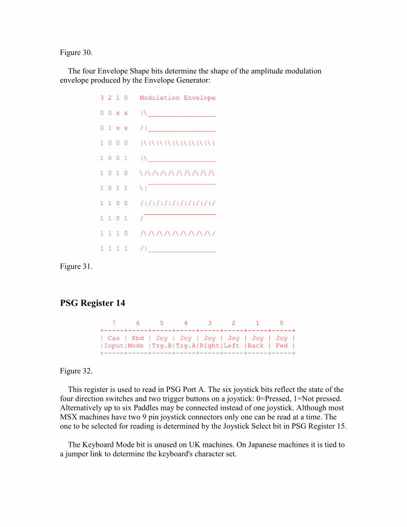
Figure 30.
The four Envelope Shape bits determine the shape of the amplitude modulation envelope produced by the Envelope Generator:
3 2 1 0 Modulation Envelope 0 0 x x |\_________________ 0 1 x x /|_________________ 1 0 0 0 |\|\|\|\|\|\|\|\|\| 1 0 0 1 |\_________________ 1 0 1 0 \/\/\/\/\/\/\/\/\/\ _________________ 1 0 1 1 \| 1 1 0 0 /|/|/|/|/|/|/|/|/|/ __________________ 1 1 0 1 / 1 1 1 0 /\/\/\/\/\/\/\/\/\/ 1 1 1 1 /|_________________
Figure 31.
PSG Register 14
7 6 5 4 3 2 1 0 +-----+-----+-----+-----+-----+-----+-----+-----+ | Cas | Kbd | Joy | Joy | Joy | Joy | Joy | Joy | |Input|Mode |Trg.B|Trg.A|Right|Left |Back | Fwd | +-----+-----+-----+-----+-----+-----+-----+-----+
Figure 32.
This register is used to read in PSG Port A. The six joystick bits reflect the state of the four direction switches and two trigger buttons on a joystick: 0=Pressed, 1=Not pressed. Alternatively up to six Paddles may be connected instead of one joystick. Although most MSX machines have two 9 pin joystick connectors only one can be read at a time. The one to be selected for reading is determined by the Joystick Select bit in PSG Register 15.
The Keyboard Mode bit is unused on UK machines. On Japanese machines it is tied to a jumper link to determine the keyboard's character set.
The Cassette Input is used to read the signal from the cassette EAR output. This is passed through a comparator to clean the edges and to convert to digital levels but is otherwise unprocessed.
PSG Register 15
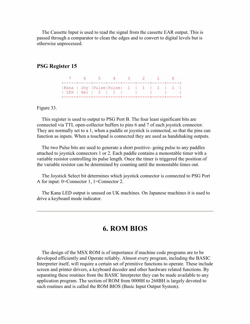
7 6 5 4 3 2 1 0 +-----+-----+-----+-----+-----+-----+-----+-----+ |Kana | Joy |Pulse|Pulse| 1 | 1 | 1 | 1 | | LED | Sel | 2 | 1 | | | | | +-----+-----+-----+-----+-----+-----+-----+-----+
Figure 33.
This register is used to output to PSG Port B. The four least significant bits are connected via TTL open-collector buffers to pins 6 and 7 of each joystick connector. They are normally set to a 1, when a paddle or joystick is connected, so that the pins can function as inputs. When a touchpad is connected they are used as handshaking outputs.
The two Pulse bits are used to generate a short positive- going pulse to any paddles attached to joystick connectors 1 or 2. Each paddle contains a monostable timer with a variable resistor controlling its pulse length. Once the timer is triggered the position of the variable resistor can be determined by counting until the monostable times out.
The Joystick Select bit determines which joystick connector is connected to PSG Port A for input: 0=Connector 1, 1=Connector 2.
The Kana LED output is unused on UK machines. On Japanese machines it is used to drive a keyboard mode indicator.
6. ROM BIOS
The design of the MSX ROM is of importance if machine code programs are to be developed efficiently and Operate reliably. Almost every program, including the BASIC Interpreter itself, will require a certain set of primitive functions to operate. These include screen and printer drivers, a keyboard decoder and other hardware related functions. By separating these routines from the BASIC Interpreter they can be made available to any application program. The section of ROM from 0000H to 268BH is largely devoted to such routines and is called the ROM BIOS (Basic Input Output System).
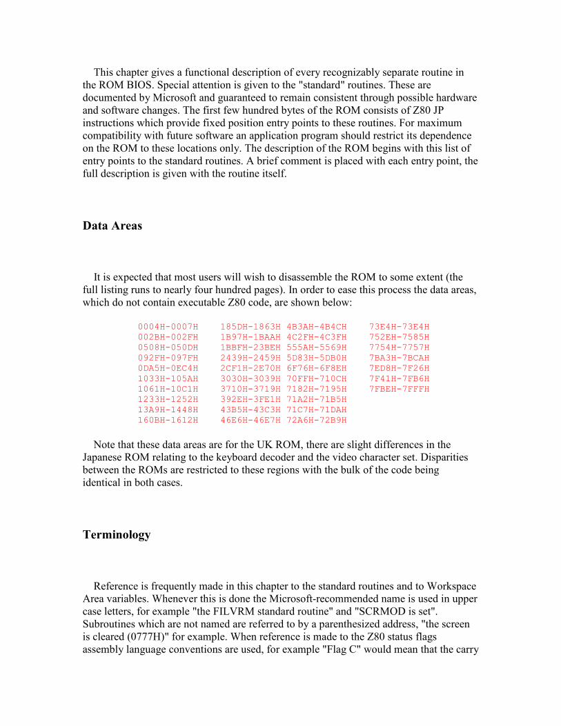
This chapter gives a functional description of every recognizably separate routine in the ROM BIOS. Special attention is given to the "standard" routines. These are documented by Microsoft and guaranteed to remain consistent through possible hardware and software changes. The first few hundred bytes of the ROM consists of Z80 JP instructions which provide fixed position entry points to these routines. For maximum compatibility with future software an application program should restrict its dependence on the ROM to these locations only. The description of the ROM begins with this list of entry points to the standard routines. A brief comment is placed with each entry point, the full description is given with the routine itself.
Data Areas
It is expected that most users will wish to disassemble the ROM to some extent (the full listing runs to nearly four hundred pages). In order to ease this process the data areas, which do not contain executable Z80 code, are shown below:
0004H-0007H 185DH-1863H 4B3AH-4B4CH 73E4H-73E4H 002BH-002FH 1B97H-1BAAH 4C2FH-4C3FH 752EH-7585H 0508H-050DH 1BBFH-23BEH 555AH-5569H 7754H-7757H 092FH-097FH 2439H-2459H 5D83H-5DB0H 7BA3H-7BCAH 0DA5H-0EC4H 2CF1H-2E70H 6F76H-6F8EH 7ED8H-7F26H 1033H-105AH 3030H-3039H 70FFH-710CH 7F41H-7FB6H 1061H-10C1H 3710H-3719H 7182H-7195H 7FBEH-7FFFH 1233H-1252H 392EH-3FE1H 71A2H-71B5H 13A9H-1448H 43B5H-43C3H 71C7H-71DAH 160BH-1612H 46E6H-46E7H 72A6H-72B9H
Note that these data areas are for the UK ROM, there are slight differences in the Japanese ROM relating to the keyboard decoder and the video character set. Disparities between the ROMs are restricted to these regions with the bulk of the code being identical in both cases.
Terminology
Reference is frequently made in this chapter to the standard routines and to Workspace Area variables. Whenever this is done the Microsoft-recommended name is used in upper case letters, for example "the FILVRM standard routine" and "SCRMOD is set". Subroutines which are not named are referred to by a parenthesized address, "the screen is cleared (0777H)" for example. When reference is made to the Z80 status flags assembly language conventions are used, for example "Flag C" would mean that the carry

flag is set while "Flag NZ" means that the zero flag is reset. The terms "EI" and "DI" mean enabled interrupts and disabled interrupts respectively.
Entry Point
Address Entry Name MSX Version Function
0000H CHKRAM 1 2 2+ tR Power-up, check RAM
0004H 1 2 2+ tR Two bytes, address of ROM character set
0006H 1 2 2+ tR One byte, VDP Data Read Port number
0007H 1 2 2+ tR One byte, VDP Data Write Port number
0008H SYNCHR 1 2 2+ tR Check BASIC program character
000BH 1 2 2+ tR NOP
000CH RDSLT 1 2 2+ tR Read RAM in any slot
000FH 1 2 2+ tR NOP
0010H CHRGTR 1 2 2+ tR Get next BASIC program character
0013H 1 2 2+ tR NOP
0014H WRSLT 1 2 2+ tR Write to RAM in any slot
0017H 1 2 2+ tR NOP
0018H OUTDO 1 2 2+ tR Output to current device
001BH 1 2 2+ tR NOP
001CH CALSLT 1 2 2+ tR Call routine in any slot
001FH 1 2 2+ tR NOP
0020H DCOMPR 1 2 2+ tR Compare register pairs HL and DE
0023H 1 2 2+ tR NOP
0024H ENASLT 1 2 2+ tR Enable any slot permanently
0027H 1 2 2+ tR NOP
0028H GETYPR 1 2 2+ tR Get BASIC operand type
002BH 1 2 2+ tR Five bytes Version Number (ID Bytes)
0030H CALLF 1 2 2+ tR Call routine in any slot

0033H 1 2 2+ tR Five NOPs
0038H KEYINT 1 2 2+ tR Interrupt handler, keyboard scan
003BH INITIO 1 2 2+ tR Initialize I/O devices
003EH INIFNK 1 2 2+ tR Initialize function key strings
0041H DISSCR 1 2 2+ tR Disable screen
0044H ENASCR 1 2 2+ tR Enable screen
0047H WRTVDP 1 2 2+ tR Write to any VDP register
004AH RDVRM 1 2 2+ tR Read byte from VRAM
004DH WRTVRM 1 2 2+ tR Write byte to VRAM
0050H SETRD 1 2 2+ tR Set up VDP for read
0053H SETWRT 1 2 2+ tR Set up VDP for write
0056H FILVRM 1 2 2+ tR Fill block of VRAM with data byte
0059H LDIRMV 1 2 2+ tR Copy block to memory, from VRAM
005CH LDIRVM 1 2 2+ tR Copy block to VRAM, from memory
005FH CHGMOD 1 2 2+ tR Change VDP mode
0062H CHGCLR 1 2 2+ tR Change VDP colours
0065H 1 2 2+ tR NOP
0066H NMI 1 2 2+ tR Non Maskable Interrupt handler
0069H CLRSPR 1 2 2+ tR Clear all sprites
006CH INITXT 1 2 2+ tR Initialize VDP to 40x24 Text Mode
006FH INIT32 1 2 2+ tR Initialize VDP to 32x24 Text Mode
0072H INIGRP 1 2 2+ tR Initialize VDP to Graphics Mode
0075H INIMLT 1 2 2+ tR Initialize VDP to Multicolour Mode
0078H SETTXT 1 2 2+ tR Set VDP to 40x24 Text Mode
007BH SETT32 1 2 2+ tR Set VDP to 32x24 Text Mode
007EH SETGRP 1 2 2+ tR Set VDP to Graphics Mode
0081H SETMLT 1 2 2+ tR Set VDP to Multicolour Mode
0084H CALPAT 1 2 2+ tR Calculate address of sprite pattern
0087H CALATR 1 2 2+ tR Calculate address of sprite attribute
008AH GSPSIZ 1 2 2+ tR Get sprite size
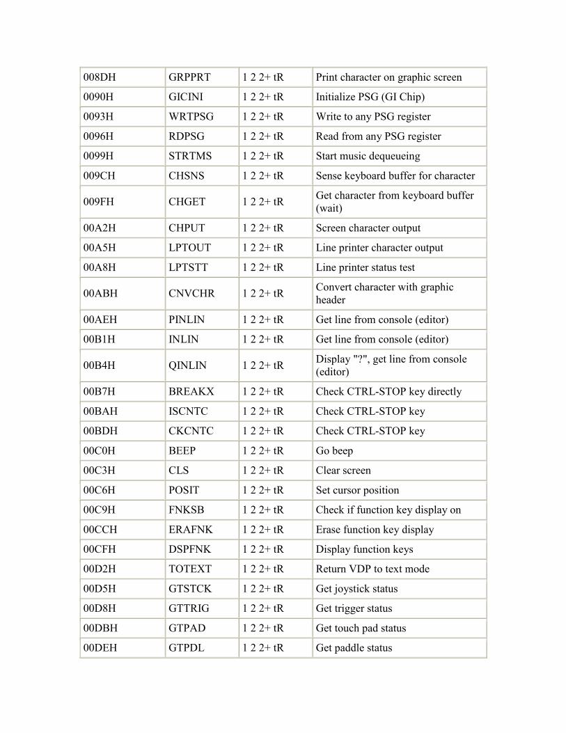
008DH GRPPRT 1 2 2+ tR Print character on graphic screen
0090H GICINI 1 2 2+ tR Initialize PSG (GI Chip)
0093H WRTPSG 1 2 2+ tR Write to any PSG register
0096H RDPSG 1 2 2+ tR Read from any PSG register
0099H STRTMS 1 2 2+ tR Start music dequeueing
009CH CHSNS 1 2 2+ tR Sense keyboard buffer for character
009FH CHGET 1 2 2+ tR Get character from keyboard buffer (wait)
00A2H CHPUT 1 2 2+ tR Screen character output
00A5H LPTOUT 1 2 2+ tR Line printer character output
00A8H LPTSTT 1 2 2+ tR Line printer status test
00ABH CNVCHR 1 2 2+ tR Convert character with graphic header
00AEH PINLIN 1 2 2+ tR Get line from console (editor)
00B1H INLIN 1 2 2+ tR Get line from console (editor)
00B4H QINLIN 1 2 2+ tR Display "?", get line from console (editor)
00B7H BREAKX 1 2 2+ tR Check CTRL-STOP key directly
00BAH ISCNTC 1 2 2+ tR Check CTRL-STOP key
00BDH CKCNTC 1 2 2+ tR Check CTRL-STOP key
00C0H BEEP 1 2 2+ tR Go beep
00C3H CLS 1 2 2+ tR Clear screen
00C6H POSIT 1 2 2+ tR Set cursor position
00C9H FNKSB 1 2 2+ tR Check if function key display on
00CCH ERAFNK 1 2 2+ tR Erase function key display
00CFH DSPFNK 1 2 2+ tR Display function keys
00D2H TOTEXT 1 2 2+ tR Return VDP to text mode
00D5H GTSTCK 1 2 2+ tR Get joystick status
00D8H GTTRIG 1 2 2+ tR Get trigger status
00DBH GTPAD 1 2 2+ tR Get touch pad status
00DEH GTPDL 1 2 2+ tR Get paddle status
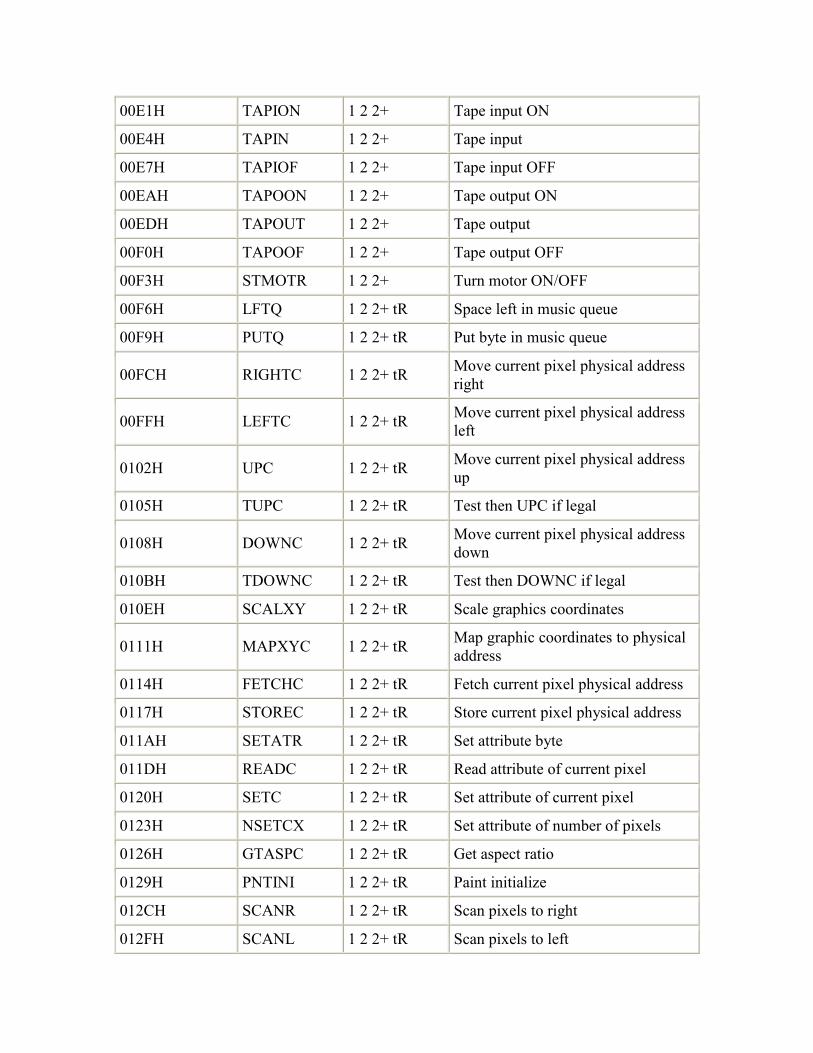
00E1H TAPION 1 2 2+ Tape input ON
00E4H TAPIN 1 2 2+ Tape input
00E7H TAPIOF 1 2 2+ Tape input OFF
00EAH TAPOON 1 2 2+ Tape output ON
00EDH TAPOUT 1 2 2+ Tape output
00F0H TAPOOF 1 2 2+ Tape output OFF
00F3H STMOTR 1 2 2+ Turn motor ON/OFF
00F6H LFTQ 1 2 2+ tR Space left in music queue
00F9H PUTQ 1 2 2+ tR Put byte in music queue
00FCH RIGHTC 1 2 2+ tR Move current pixel physical address right
00FFH LEFTC 1 2 2+ tR Move current pixel physical address left
0102H UPC 1 2 2+ tR Move current pixel physical address up
0105H TUPC 1 2 2+ tR Test then UPC if legal
0108H DOWNC 1 2 2+ tR Move current pixel physical address down
010BH TDOWNC 1 2 2+ tR Test then DOWNC if legal
010EH SCALXY 1 2 2+ tR Scale graphics coordinates
0111H MAPXYC 1 2 2+ tR Map graphic coordinates to physical address
0114H FETCHC 1 2 2+ tR Fetch current pixel physical address
0117H STOREC 1 2 2+ tR Store current pixel physical address
011AH SETATR 1 2 2+ tR Set attribute byte
011DH READC 1 2 2+ tR Read attribute of current pixel
0120H SETC 1 2 2+ tR Set attribute of current pixel
0123H NSETCX 1 2 2+ tR Set attribute of number of pixels
0126H GTASPC 1 2 2+ tR Get aspect ratio
0129H PNTINI 1 2 2+ tR Paint initialize
012CH SCANR 1 2 2+ tR Scan pixels to right
012FH SCANL 1 2 2+ tR Scan pixels to left
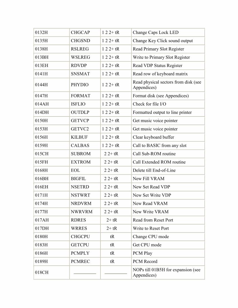
0132H CHGCAP 1 2 2+ tR Change Caps Lock LED
0135H CHGSND 1 2 2+ tR Change Key Click sound output
0138H RSLREG 1 2 2+ tR Read Primary Slot Register
013BH WSLREG 1 2 2+ tR Write to Primary Slot Register
013EH RDVDP 1 2 2+ tR Read VDP Status Register
0141H SNSMAT 1 2 2+ tR Read row of keyboard matrix
0144H PHYDIO 1 2 2+ tR Read physical sectors from disk (see Appendices)
0147H FORMAT 1 2 2+ tR Format disk (see Appendices)
014AH ISFLIO 1 2 2+ tR Check for file I/O
014DH OUTDLP 1 2 2+ tR Formatted output to line printer
0150H GETVCP 1 2 2+ tR Get music voice pointer
0153H GETVC2 1 2 2+ tR Get music voice pointer
0156H KILBUF 1 2 2+ tR Clear keyboard buffer
0159H CALBAS 1 2 2+ tR Call to BASIC from any slot
015CH SUBROM 2 2+ tR Call Sub-ROM routine
015FH EXTROM 2 2+ tR Call Extended ROM routine
0168H EOL 2 2+ tR Delete till End-of-Line
016BH BIGFIL 2 2+ tR New Fill VRAM
016EH NSETRD 2 2+ tR New Set Read VDP
0171H NSTWRT 2 2+ tR New Set Write VDP
0174H NRDVRM 2 2+ tR New Read VRAM
0177H NWRVRM 2 2+ tR New Write VRAM
017AH RDRES 2+ tR Read from Reset Port
017DH WRRES 2+ tR Write to Reset Port
0180H CHGCPU tR Change CPU mode
0183H GETCPU tR Get CPU mode
0186H PCMPLY tR PCM Play
0189H PCMREC tR PCM Record
018CH NOPs till 01B5H for expansion (see Appendices)

Address ... 01B6H (from 000CH) Name ...... RDSLT (Read from Slot) Input ..... A=Slot ID, HL=Address Exit ...... A=Byte read Modifies .. AF, BC, DE, DI
Standard routine to read a single byte from memory in any slot. The Slot Identifier is composed of a Primary Slot number a Secondary Slot number and a flag:
7 6 5 4 3 2 1 0 +-------+-------+-------+-------+---------------+---------------+ | Flag | 0 | 0 | 0 |Secondary Slot#| Primary Slot# | +-------+-------+-------+-------+---------------+---------------+
Figure 34: Slot ID.
The flag is normally 0 but must be 1 if a Secondary Slot number is included in the Slot ID. The memory address and Slot ID are first processed (027EH) to yield a set of bit masks to apply to the relevant slot register. If a Secondary Slot number is specified then the Secondary Slot Register is first modified to select the relevant page from that Secondary Slot (02A3H). The Primary Slot is then switched in to the Z80 address space, the byte read and the Primary Slot restored to its original setting via the RDPRIM routine in the Workspace Area. Finally, if a Secondary Slot number is included in the Slot ID, the original Secondary Slot Register setting is restored (01ECH).
Note that, unless it is the slot containing the Workspace Area, any attempt to access page 3 (C000H to FFFFH) will cause the system to crash as RDPRIM will switch itself out. Note also that interrupts are left disabled by all the memory switching routines.
Address ... 01D1H (from 0014H) Name ...... WRSLT (Write to Slot) Input ..... A=Slot ID, HL=Address, E=Byte to write Exit ...... None Modifies .. AF, BC, D, DI
Standard routine to write a single byte to memory in any slot. Its operation is fundamentally the same as that of the RDSLT standard routine except that the Workspace Area routine WRPRIM is used rather than RDPRIM.
BIOS Address .. 002BH Length ........ 5
The bytes from 002BH to 002FH of the main ROM presents its version number and several other data, the MSX ROM Version Identification Bytes:
002BH 7 6 5 4 3 2 1 0
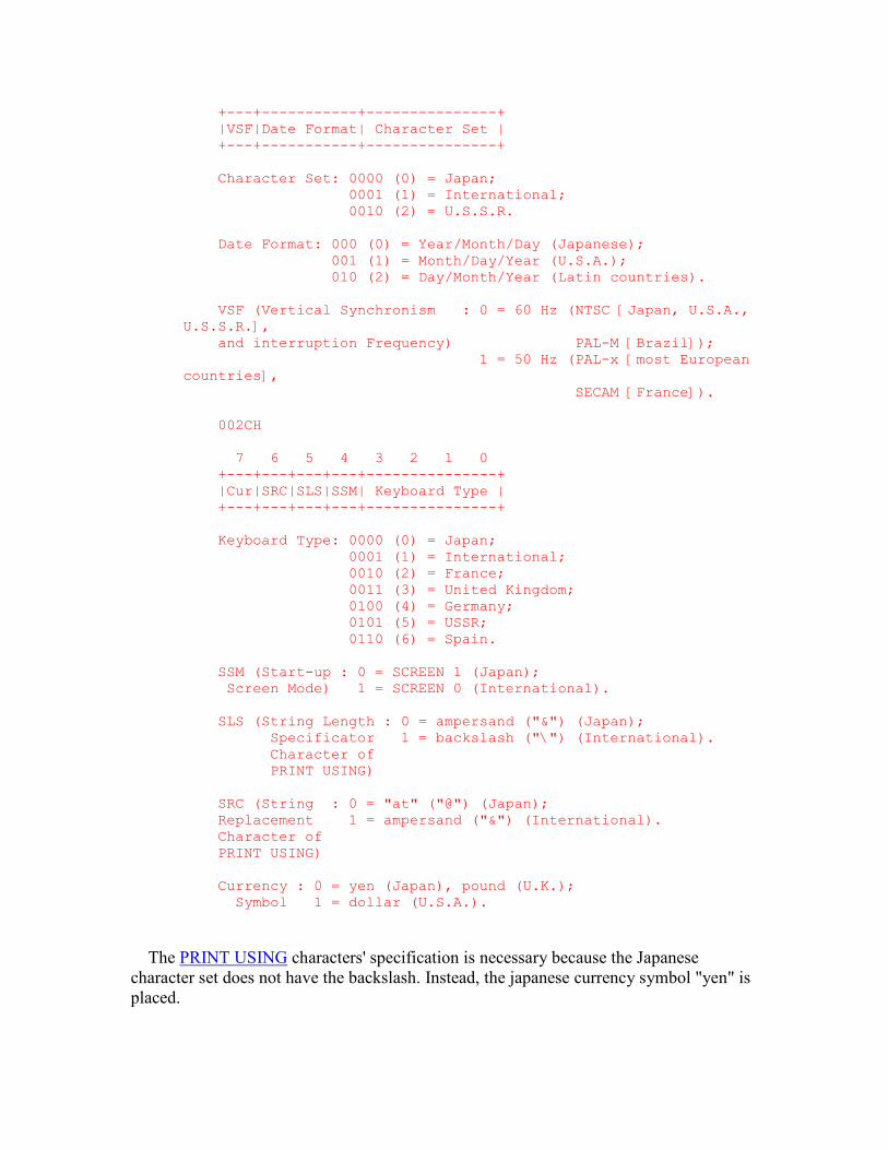
+---+-----------+---------------+ |VSF|Date Format| Character Set | +---+-----------+---------------+ Character Set: 0000 (0) = Japan; 0001 (1) = International; 0010 (2) = U.S.S.R. Date Format: 000 (0) = Year/Month/Day (Japanese); 001 (1) = Month/Day/Year (U.S.A.); 010 (2) = Day/Month/Year (Latin countries). VSF (Vertical Synchronism : 0 = 60 Hz (NTSC [Japan, U.S.A., U.S.S.R.], and interruption Frequency) PAL-M [Brazil]); 1 = 50 Hz (PAL-x [most European countries], SECAM [France]). 002CH 7 6 5 4 3 2 1 0 +---+---+---+---+---------------+ |Cur|SRC|SLS|SSM| Keyboard Type | +---+---+---+---+---------------+ Keyboard Type: 0000 (0) = Japan; 0001 (1) = International; 0010 (2) = France; 0011 (3) = United Kingdom; 0100 (4) = Germany; 0101 (5) = USSR; 0110 (6) = Spain. SSM (Start-up : 0 = SCREEN 1 (Japan); Screen Mode) 1 = SCREEN 0 (International). SLS (String Length : 0 = ampersand ("&") (Japan); Specificator 1 = backslash ("\") (International). Character of PRINT USING) SRC (String : 0 = "at" ("@") (Japan); Replacement 1 = ampersand ("&") (International). Character of PRINT USING) Currency : 0 = yen (Japan), pound (U.K.); Symbol 1 = dollar (U.S.A.).
The PRINT USING characters' specification is necessary because the Japanese character set does not have the backslash. Instead, the japanese currency symbol "yen" is placed.

002DH presents the MSX version:
00000000 (0) = MSX
00000001 (1) = MSX2
00000010 (2) = MSX2+
00000011 (3) = turbo R 002EH 7 6 5 4 3 2 1 0 +---+---+---+---+---+---+---+---+ | ? | ? | ? | ? | ? | ? | ? | ? | +---+---+---+---+---+---+---+---+ 002FH 7 6 5 4 3 2 1 0 +---+---+---+---+---+---+---+---+ | ? | ? | ? | ? | ? | ? | ? | ? | +---+---+---+---+---+---+---+---+ Address ... 0205H (from 0030H) Name ...... CALLF (Call Far routine) Input ..... None Exit ...... None Modifies .. AF', BC', DE', HL', IX, IY, DI
Standard routine to call an address in any slot. The Slot ID and address are supplied as inline parameters rather than in registers to fit inside a hook (Chapter 6), for example:
RST 30H DEFB Slot ID DEFW Address RET
The Slot ID is first collected and placed in the high byte of register pair IY. The address is then placed in register pair IX and control drops into the CALSLT standard routine.
Address ... 0217H (from 001CH) Name ...... CALSLT (Call Slot routine) Input ..... IY(High byte)=Slot ID, IX=Address Exit ...... None Modifies .. AF', BC', DE', HL', DI
Standard routine to call an address in any slot. Its operation is fundamentally the same as that of the RDSLT standard routine except that the Workspace Area routine CLPRIM is used rather than RDPRIM. Note that CALBAS and CALLF are just specialized entry points to this standard routine which offer a reduction in the amount of code required.
Address ... 025EH (from 0024H)
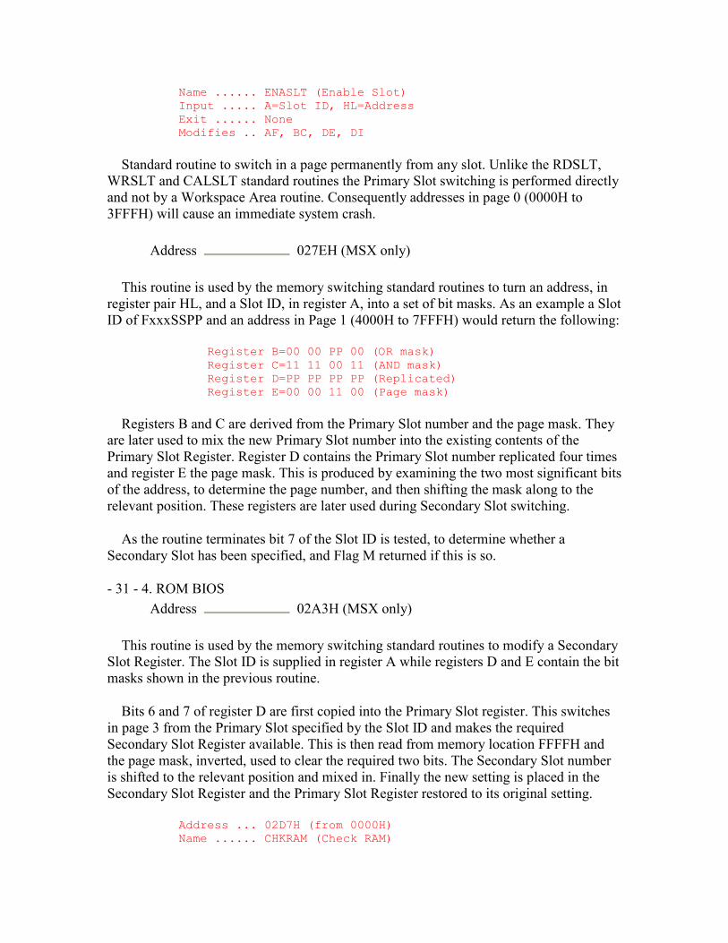
Name ...... ENASLT (Enable Slot) Input ..... A=Slot ID, HL=Address Exit ...... None Modifies .. AF, BC, DE, DI
Standard routine to switch in a page permanently from any slot. Unlike the RDSLT, WRSLT and CALSLT standard routines the Primary Slot switching is performed directly and not by a Workspace Area routine. Consequently addresses in page 0 (0000H to 3FFFH) will cause an immediate system crash.
Address 027EH (MSX only)
This routine is used by the memory switching standard routines to turn an address, in register pair HL, and a Slot ID, in register A, into a set of bit masks. As an example a Slot ID of FxxxSSPP and an address in Page 1 (4000H to 7FFFH) would return the following:
Register B=00 00 PP 00 (OR mask) Register C=11 11 00 11 (AND mask) Register D=PP PP PP PP (Replicated) Register E=00 00 11 00 (Page mask)
Registers B and C are derived from the Primary Slot number and the page mask. They are later used to mix the new Primary Slot number into the existing contents of the Primary Slot Register. Register D contains the Primary Slot number replicated four times and register E the page mask. This is produced by examining the two most significant bits of the address, to determine the page number, and then shifting the mask along to the relevant position. These registers are later used during Secondary Slot switching.
As the routine terminates bit 7 of the Slot ID is tested, to determine whether a Secondary Slot has been specified, and Flag M returned if this is so.
- 31 - 4. ROM BIOS Address 02A3H (MSX only)
This routine is used by the memory switching standard routines to modify a Secondary Slot Register. The Slot ID is supplied in register A while registers D and E contain the bit masks shown in the previous routine.
Bits 6 and 7 of register D are first copied into the Primary Slot register. This switches in page 3 from the Primary Slot specified by the Slot ID and makes the required Secondary Slot Register available. This is then read from memory location FFFFH and the page mask, inverted, used to clear the required two bits. The Secondary Slot number is shifted to the relevant position and mixed in. Finally the new setting is placed in the Secondary Slot Register and the Primary Slot Register restored to its original setting.
Address ... 02D7H (from 0000H) Name ...... CHKRAM (Check RAM)

Input ..... None Exit ...... None Modifies .. AF, BC, DE, HL, SP
Standard routine to perform memory initialization at power- up. It non-destructively tests for RAM in pages 2 and 3 in all sixteen possible slots then sets the Primary and Secondary Slot registers to switch in the largest area found. The entire Workspace Area (F380H to FFC9H) is zeroed and EXPTBL and SLTTBL filled in to map any expansion interfaces in existence Interrupt Mode 1 is set and control transfers to the remainder of the power-up initialization routine (7C76H).
Address ... 03FBH (from 00BAH) Name ...... ISCNTC (Is Control-stop) Input ..... None Exit ...... None Modifies .. AF, EI
Standard routine to check whether the CTRL-STOP or STOP keys have been pressed. It is used by the BASIC Interpreter at the end of each statement to check for program termination. BASROM is first examined to see if it contains a non-zero value, if so the routine terminates immediately. This is to prevent users breaking into any extension ROM containing a BASIC program.
INTFLG is then checked to determine whether the interrupt handler has placed the CTRL-STOP or STOP key codes (03H or 04H) there. If STOP has been detected then the cursor is turned on (09DAH) and INTFLG continually checked until one of the two key codes reappears. The cursor is then turned off (0A27H) and, if the key is STOP, the routine terminates.
If CTRL-STOP has been detected then the keyboard buffer is first cleared via the KILBUF standard routine and TRPTBL is checked to see whether an "ON STOP GOSUB" statement is active. If so the relevant entry in TRPTBL is updated (0EF1H) and the routine terminates as the event will be handled by the Interpreter Runloop. Otherwise the ENASLT standard routine is used to switch in page 1 from the MSX ROM, in case an extension ROM is using the routine, and control transfers to the "STOP" statement handler (63E6H).
Address ... 0468H (from 0156H) Name ...... KILBUF (Kill keyboard Buffer) Input ..... None Exit ...... None Modifies .. HL
Standard Routine to clear the forty character type-ahead keyboard buffer KEYBUF. There are two pointers into this buffer, PUTPNT where the interrupt handler places characters, and GETPNT where application programs fetch them from. As the number of characters in the buffer is indicated by the difference between these two pointers KEYBUF is emptied simply by making them both equal.
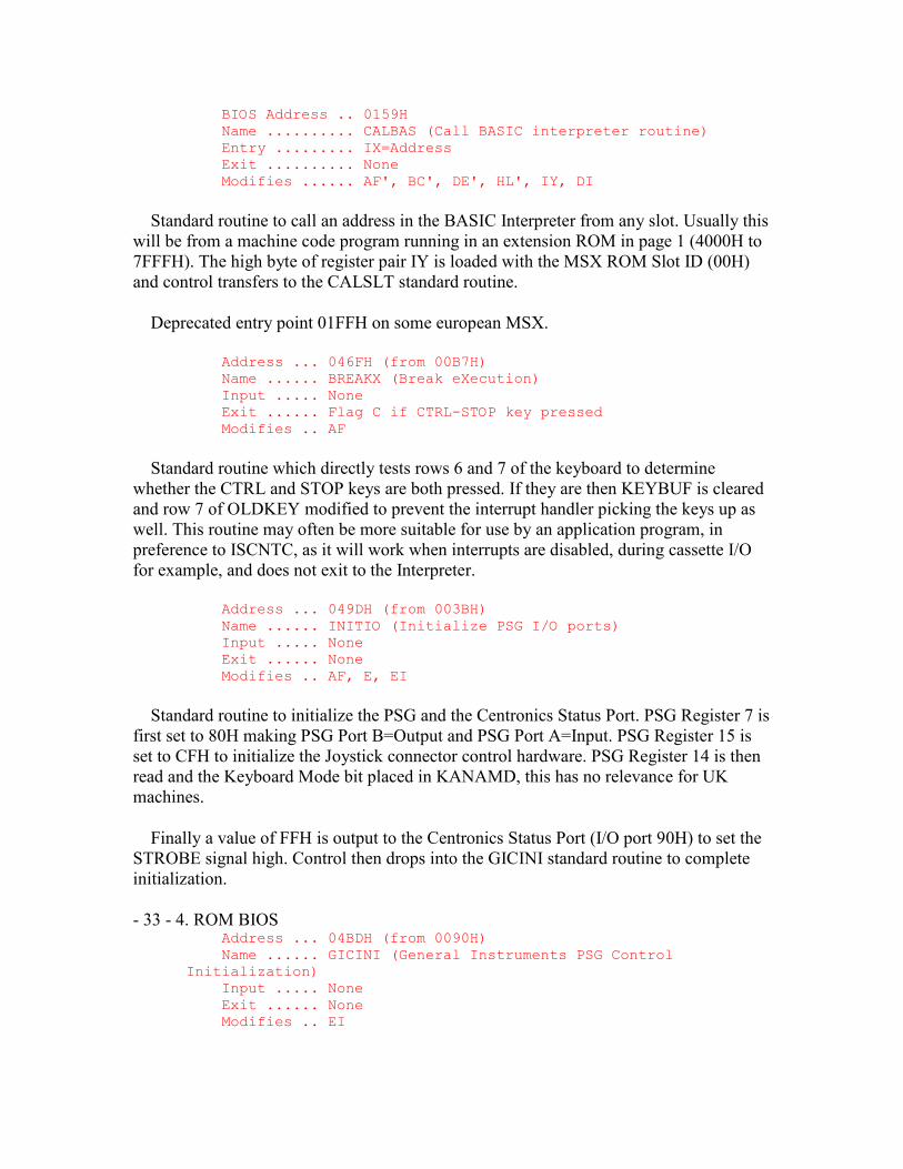
BIOS Address .. 0159H Name .......... CALBAS (Call BASIC interpreter routine) Entry ......... IX=Address Exit .......... None Modifies ...... AF', BC', DE', HL', IY, DI
Standard routine to call an address in the BASIC Interpreter from any slot. Usually this will be from a machine code program running in an extension ROM in page 1 (4000H to 7FFFH). The high byte of register pair IY is loaded with the MSX ROM Slot ID (00H) and control transfers to the CALSLT standard routine.
Deprecated entry point 01FFH on some european MSX.
Address ... 046FH (from 00B7H) Name ...... BREAKX (Break eXecution) Input ..... None Exit ...... Flag C if CTRL-STOP key pressed Modifies .. AF
Standard routine which directly tests rows 6 and 7 of the keyboard to determine whether the CTRL and STOP keys are both pressed. If they are then KEYBUF is cleared and row 7 of OLDKEY modified to prevent the interrupt handler picking the keys up as well. This routine may often be more suitable for use by an application program, in preference to ISCNTC, as it will work when interrupts are disabled, during cassette I/O for example, and does not exit to the Interpreter.
Address ... 049DH (from 003BH) Name ...... INITIO (Initialize PSG I/O ports) Input ..... None Exit ...... None Modifies .. AF, E, EI
Standard routine to initialize the PSG and the Centronics Status Port. PSG Register 7 is first set to 80H making PSG Port B=Output and PSG Port A=Input. PSG Register 15 is set to CFH to initialize the Joystick connector control hardware. PSG Register 14 is then read and the Keyboard Mode bit placed in KANAMD, this has no relevance for UK machines.
Finally a value of FFH is output to the Centronics Status Port (I/O port 90H) to set the STROBE signal high. Control then drops into the GICINI standard routine to complete initialization.
- 33 - 4. ROM BIOS Address ... 04BDH (from 0090H) Name ...... GICINI (General Instruments PSG Control Initialization) Input ..... None Exit ...... None Modifies .. EI
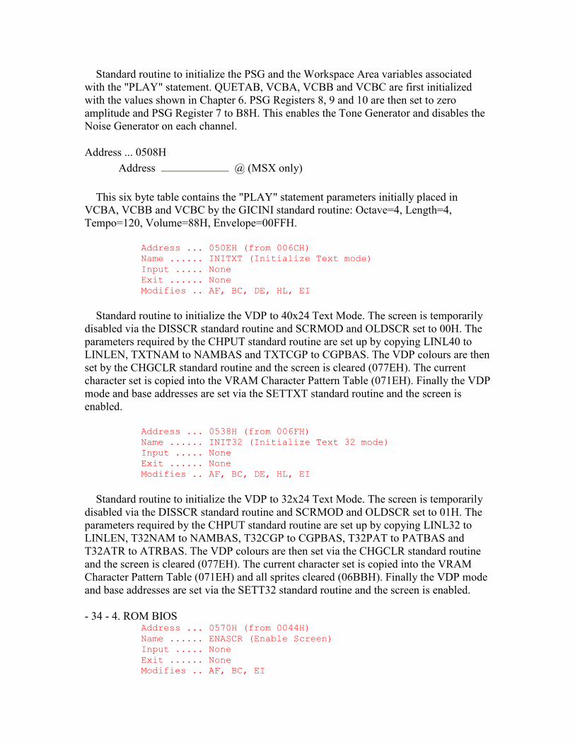
Standard routine to initialize the PSG and the Workspace Area variables associated with the "PLAY" statement. QUETAB, VCBA, VCBB and VCBC are first initialized with the values shown in Chapter 6. PSG Registers 8, 9 and 10 are then set to zero amplitude and PSG Register 7 to B8H. This enables the Tone Generator and disables the Noise Generator on each channel.
Address ... 0508H Address @ (MSX only)
This six byte table contains the "PLAY" statement parameters initially placed in VCBA, VCBB and VCBC by the GICINI standard routine: Octave=4, Length=4, Tempo=120, Volume=88H, Envelope=00FFH.
Address ... 050EH (from 006CH) Name ...... INITXT (Initialize Text mode) Input ..... None Exit ...... None Modifies .. AF, BC, DE, HL, EI
Standard routine to initialize the VDP to 40x24 Text Mode. The screen is temporarily disabled via the DISSCR standard routine and SCRMOD and OLDSCR set to 00H. The parameters required by the CHPUT standard routine are set up by copying LINL40 to LINLEN, TXTNAM to NAMBAS and TXTCGP to CGPBAS. The VDP colours are then set by the CHGCLR standard routine and the screen is cleared (077EH). The current character set is copied into the VRAM Character Pattern Table (071EH). Finally the VDP mode and base addresses are set via the SETTXT standard routine and the screen is enabled.
Address ... 0538H (from 006FH) Name ...... INIT32 (Initialize Text 32 mode) Input ..... None Exit ...... None Modifies .. AF, BC, DE, HL, EI
Standard routine to initialize the VDP to 32x24 Text Mode. The screen is temporarily disabled via the DISSCR standard routine and SCRMOD and OLDSCR set to 01H. The parameters required by the CHPUT standard routine are set up by copying LINL32 to LINLEN, T32NAM to NAMBAS, T32CGP to CGPBAS, T32PAT to PATBAS and T32ATR to ATRBAS. The VDP colours are then set via the CHGCLR standard routine and the screen is cleared (077EH). The current character set is copied into the VRAM Character Pattern Table (071EH) and all sprites cleared (06BBH). Finally the VDP mode and base addresses are set via the SETT32 standard routine and the screen is enabled.
- 34 - 4. ROM BIOS Address ... 0570H (from 0044H) Name ...... ENASCR (Enable Screen) Input ..... None Exit ...... None Modifies .. AF, BC, EI
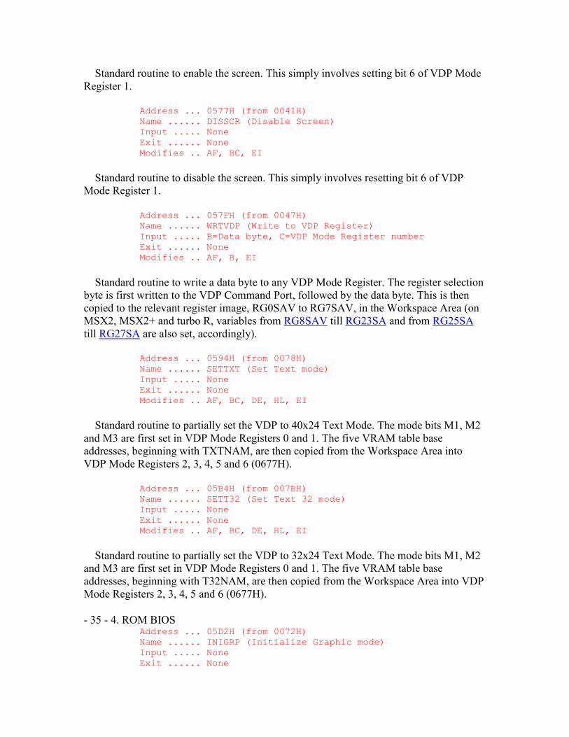
Standard routine to enable the screen. This simply involves setting bit 6 of VDP Mode Register 1.
Address ... 0577H (from 0041H) Name ...... DISSCR (Disable Screen) Input ..... None Exit ...... None Modifies .. AF, BC, EI
Standard routine to disable the screen. This simply involves resetting bit 6 of VDP Mode Register 1.
Address ... 057FH (from 0047H) Name ...... WRTVDP (Write to VDP Register) Input ..... B=Data byte, C=VDP Mode Register number Exit ...... None Modifies .. AF, B, EI
Standard routine to write a data byte to any VDP Mode Register. The register selection byte is first written to the VDP Command Port, followed by the data byte. This is then copied to the relevant register image, RG0SAV to RG7SAV, in the Workspace Area (on MSX2, MSX2+ and turbo R, variables from RG8SAV till RG23SA and from RG25SA till RG27SA are also set, accordingly).
Address ... 0594H (from 0078H) Name ...... SETTXT (Set Text mode) Input ..... None Exit ...... None Modifies .. AF, BC, DE, HL, EI
Standard routine to partially set the VDP to 40x24 Text Mode. The mode bits M1, M2 and M3 are first set in VDP Mode Registers 0 and 1. The five VRAM table base addresses, beginning with TXTNAM, are then copied from the Workspace Area into VDP Mode Registers 2, 3, 4, 5 and 6 (0677H).
Address ... 05B4H (from 007BH) Name ...... SETT32 (Set Text 32 mode) Input ..... None Exit ...... None Modifies .. AF, BC, DE, HL, EI
Standard routine to partially set the VDP to 32x24 Text Mode. The mode bits M1, M2 and M3 are first set in VDP Mode Registers 0 and 1. The five VRAM table base addresses, beginning with T32NAM, are then copied from the Workspace Area into VDP Mode Registers 2, 3, 4, 5 and 6 (0677H).
- 35 - 4. ROM BIOS Address ... 05D2H (from 0072H) Name ...... INIGRP (Initialize Graphic mode) Input ..... None Exit ...... None
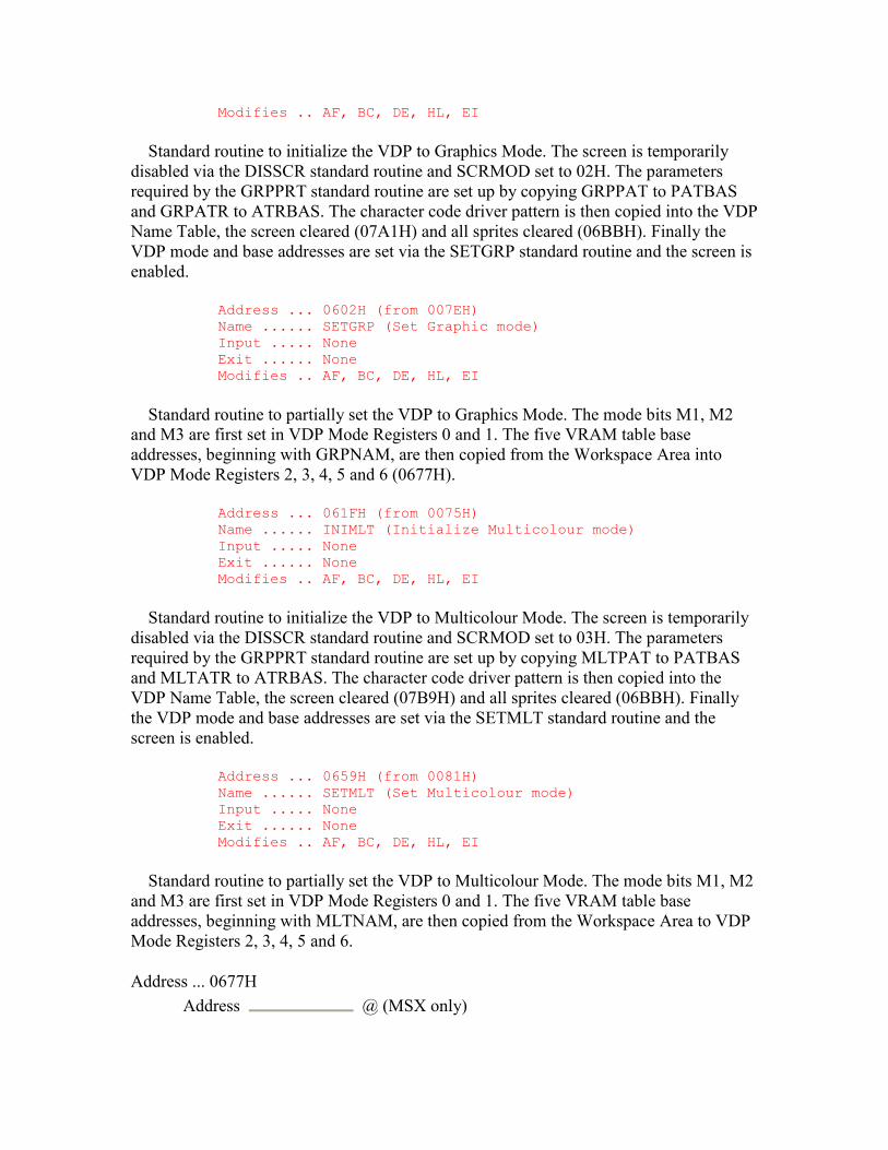
Modifies .. AF, BC, DE, HL, EI
Standard routine to initialize the VDP to Graphics Mode. The screen is temporarily disabled via the DISSCR standard routine and SCRMOD set to 02H. The parameters required by the GRPPRT standard routine are set up by copying GRPPAT to PATBAS and GRPATR to ATRBAS. The character code driver pattern is then copied into the VDP Name Table, the screen cleared (07A1H) and all sprites cleared (06BBH). Finally the VDP mode and base addresses are set via the SETGRP standard routine and the screen is enabled.
Address ... 0602H (from 007EH) Name ...... SETGRP (Set Graphic mode) Input ..... None Exit ...... None Modifies .. AF, BC, DE, HL, EI
Standard routine to partially set the VDP to Graphics Mode. The mode bits M1, M2 and M3 are first set in VDP Mode Registers 0 and 1. The five VRAM table base addresses, beginning with GRPNAM, are then copied from the Workspace Area into VDP Mode Registers 2, 3, 4, 5 and 6 (0677H).
Address ... 061FH (from 0075H) Name ...... INIMLT (Initialize Multicolour mode) Input ..... None Exit ...... None Modifies .. AF, BC, DE, HL, EI
Standard routine to initialize the VDP to Multicolour Mode. The screen is temporarily disabled via the DISSCR standard routine and SCRMOD set to 03H. The parameters required by the GRPPRT standard routine are set up by copying MLTPAT to PATBAS and MLTATR to ATRBAS. The character code driver pattern is then copied into the VDP Name Table, the screen cleared (07B9H) and all sprites cleared (06BBH). Finally the VDP mode and base addresses are set via the SETMLT standard routine and the screen is enabled.
Address ... 0659H (from 0081H) Name ...... SETMLT (Set Multicolour mode) Input ..... None Exit ...... None Modifies .. AF, BC, DE, HL, EI
Standard routine to partially set the VDP to Multicolour Mode. The mode bits M1, M2 and M3 are first set in VDP Mode Registers 0 and 1. The five VRAM table base addresses, beginning with MLTNAM, are then copied from the Workspace Area to VDP Mode Registers 2, 3, 4, 5 and 6.
Address ... 0677H Address @ (MSX only)
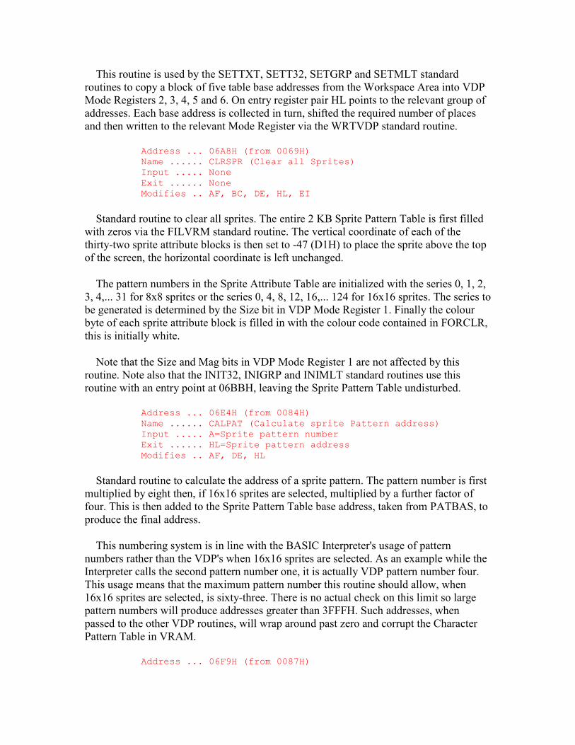
This routine is used by the SETTXT, SETT32, SETGRP and SETMLT standard routines to copy a block of five table base addresses from the Workspace Area into VDP Mode Registers 2, 3, 4, 5 and 6. On entry register pair HL points to the relevant group of addresses. Each base address is collected in turn, shifted the required number of places and then written to the relevant Mode Register via the WRTVDP standard routine.
Address ... 06A8H (from 0069H) Name ...... CLRSPR (Clear all Sprites) Input ..... None Exit ...... None Modifies .. AF, BC, DE, HL, EI
Standard routine to clear all sprites. The entire 2 KB Sprite Pattern Table is first filled with zeros via the FILVRM standard routine. The vertical coordinate of each of the thirty-two sprite attribute blocks is then set to -47 (D1H) to place the sprite above the top of the screen, the horizontal coordinate is left unchanged.
The pattern numbers in the Sprite Attribute Table are initialized with the series 0, 1, 2, 3, 4,... 31 for 8x8 sprites or the series 0, 4, 8, 12, 16,... 124 for 16x16 sprites. The series to be generated is determined by the Size bit in VDP Mode Register 1. Finally the colour byte of each sprite attribute block is filled in with the colour code contained in FORCLR, this is initially white.
Note that the Size and Mag bits in VDP Mode Register 1 are not affected by this routine. Note also that the INIT32, INIGRP and INIMLT standard routines use this routine with an entry point at 06BBH, leaving the Sprite Pattern Table undisturbed.
Address ... 06E4H (from 0084H) Name ...... CALPAT (Calculate sprite Pattern address) Input ..... A=Sprite pattern number Exit ...... HL=Sprite pattern address Modifies .. AF, DE, HL
Standard routine to calculate the address of a sprite pattern. The pattern number is first multiplied by eight then, if 16x16 sprites are selected, multiplied by a further factor of four. This is then added to the Sprite Pattern Table base address, taken from PATBAS, to produce the final address.
This numbering system is in line with the BASIC Interpreter's usage of pattern numbers rather than the VDP's when 16x16 sprites are selected. As an example while the Interpreter calls the second pattern number one, it is actually VDP pattern number four. This usage means that the maximum pattern number this routine should allow, when 16x16 sprites are selected, is sixty-three. There is no actual check on this limit so large pattern numbers will produce addresses greater than 3FFFH. Such addresses, when passed to the other VDP routines, will wrap around past zero and corrupt the Character Pattern Table in VRAM.
Address ... 06F9H (from 0087H)
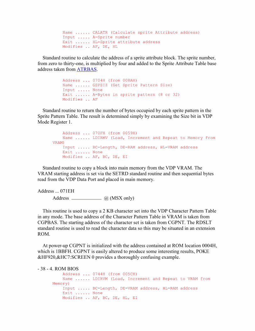
Name ...... CALATR (Calculate sprite Attribute address) Input ..... A=Sprite number Exit ...... HL=Sprite attribute address Modifies .. AF, DE, HL
Standard routine to calculate the address of a sprite attribute block. The sprite number, from zero to thirty-one, is multiplied by four and added to the Sprite Attribute Table base address taken from ATRBAS.
Address ... 0704H (from 008AH) Name ...... GSPSIZ (Get Sprite Pattern Size) Input ..... None Exit ...... A=Bytes in sprite pattern (8 or 32) Modifies .. AF
Standard routine to return the number of bytes occupied by each sprite pattern in the Sprite Pattern Table. The result is determined simply by examining the Size bit in VDP Mode Register 1.
Address ... 070FH (from 0059H) Name ...... LDIRMV (Load, Increment and Repeat to Memory from VRAM) Input ..... BC=Length, DE=RAM address, HL=VRAM address Exit ...... None Modifies .. AF, BC, DE, EI
Standard routine to copy a block into main memory from the VDP VRAM. The VRAM starting address is set via the SETRD standard routine and then sequential bytes read from the VDP Data Port and placed in main memory.
Address ... 071EH Address @ (MSX only)
This routine is used to copy a 2 KB character set into the VDP Character Pattern Table in any mode. The base address of the Character Pattern Table in VRAM is taken from CGPBAS. The starting address of the character set is taken from CGPNT. The RDSLT standard routine is used to read the character data so this may be situated in an extension ROM.
At power-up CGPNT is initialized with the address contained at ROM location 0004H, which is 1BBFH. CGPNT is easily altered to produce some interesting results, POKE &HF920,&HC7:SCREEN 0 provides a thoroughly confusing example.
- 38 - 4. ROM BIOS Address ... 0744H (from 005CH) Name ...... LDIRVM (Load, Increment and Repeat to VRAM from Memory) Input ..... BC=Length, DE=VRAM address, HL=RAM address Exit ...... None Modifies .. AF, BC, DE, HL, EI
Standard routine to copy a block to VRAM from main memory. The VRAM starting address is set via the SETWRT standard routine and then sequential bytes taken from main memory and written to the VDP Data Port.
Address ... 0777H Address @ (MSX only)
This routine will clear the screen in any VDP mode. In 40x24 Text Mode and 32x24 Text Mode the Name Table, whose base address is taken from NAMBAS, is first filled with ASCII spaces. The cursor is then set to the home position (0A7FH) and LINTTB, the line termination table, re-initialized. Finally the function key display is restored, if it is enabled, via the FNKSB standard routine.
In Graphics Mode the border colour is first set via VDP Mode Register 7 (0832H). The Colour Table is then filled with the background colour code, taken from BAKCLR, for both 0 and 1 pixels. Finally the Character Pattern Table is filled with zeroes.
In Multicolour Mode the border colour is first set via VDP Mode Register 7 (0832H). The Character Pattern Table is then filled with the background colour taken from BAKCLR.
Address ... 07CDH (from 004DH) Name ...... WRTVRM (Write to VRAM) Input ..... A=Data byte, HL=VRAM address Exit ...... None Modifies .. EI
Standard routine to write a single byte to the VDP VRAM. The VRAM address is first set up via the SETWRT standard routine and then the data byte written to the VDP Data Port. Note that the two seemingly spurious EX(SP),HL instructions in this routine, and several others, are required to meet the VDP's timing constraints.
Address ... 07D7H (from 004AH) Name ...... RDVRM (Read from VRAM) Input ..... HL=VRAM address Exit ...... A=Byte read Modifies .. AF, EI
Standard routine to read a single byte from the VDP VRAM. The VRAM address is first set up via the SETRD standard routine and then the byte read from the VDP Data Port.
- 39 - 4. ROM BIOS Address ... 07DFH (from 0053H) Name ...... SETWRT (Set VDP for Writing) Input ..... HL=VRAM address Exit ...... None Modifies .. AF, EI
Standard routine to set up the VDP for subsequent writes to VRAM via the Data Port. The address contained in register pair HL is written to the VDP Command Port LSB first, MSB second as shown in Figure 7. Addresses greater than 3FFFH will wrap around past zero as the two most significant bits of the address are ignored.
Address ... 07ECH (from 0050H) Name ...... SETRD (Set VDP for Reading) Input ..... HL=VRAM address Exit ...... None Modifies .. AF, EI
Standard routine to set up the VDP for subsequent reads from VRAM via the Data Port. The address contained in register pair HL is written to the VDP Command Port LSB first, MSB second as shown in Figure 7. Addresses greater than 3FFFH will wrap around past zero as the two most significant bits of the address are ignored.
Address ... 07F7H (from 0062H) Name ...... CHGCLR (Change Colour) Input ..... None Exit ...... None Modifies .. AF, BC, HL, EI
Standard routine to set the VDP colours. SCRMOD is first examined to determine the appropriate course of action. In 40x24 Text Mode the contents of BAKCLR and FORCLR are written to VDP Mode Register 7 to set the colour of the 0 and 1 pixels, these are initially blue and white. Note that in this mode there is no way of specifying the border colour, this will be the same as the 0 pixel colour. In 32x24 Text Mode, Graphics Mode or Multicolour Mode the contents of BDRCLR are written to VDP Mode Register 7 to set the colour of the border, this is initially blue. Also in 32x24 Text Mode the contents of BAKCLR and FORCLR are copied to the whole of the Colour Table to determine the 0 and 1 pixel colours.
Address ... 0815H (from 0056H) Name ...... FILVRM (Fill VRAM) Input ..... A=Data byte, BC=Length, HL=VRAM address Exit ...... None Modifies .. AF, BC, EI
Standard routine to fill a block of the VDP VRAM with a single data byte. The VRAM starting address, contained in register pair HL, is first set up via the SETWRT standard routine. The data byte is then repeatedly written to the VDP Data Port to fill successive VRAM locations.
Address ... 083BH (from 00D2H) Name ...... TOTEXT (To Text mode) Input ..... None Exit ...... None Modifies .. AF, BC, DE, HL, EI
Standard routine to return the VDP to either 40x24 Text Mode or 32x24 Text Mode if it is currently in Graphics Mode or Multicolour Mode. It is used by the BASIC Interpreter Mainloop and by the "INPUT" statement handler. Whenever the INITXT or INIT32 standard routines are used the mode byte, 00H or 01H, is copied into OLDSCR. If the mode is subsequently changed to Graphics Mode or Multicolour Mode, and then has to be returned to one of the two text modes for keyboard input, this routine ensures that it returns to the same one.
SCRMOD is first examined and, if the screen is already in either text mode, the routine simply terminates with no action. Otherwise the previous text mode is taken from OLDSCR and passed to the CHGMOD standard routine.
Address ... 0848H (from 00C3H) Name ...... CLS (Clear Screen) Input ..... Flag Z Exit ...... None Modifies .. AF, BC, DE, EI
Standard routine to clear the screen in any mode, it does nothing but call the routine at 0777H. This is actually the "CLS" statement handler and, because this indicates that there is illegal text after the statement, it will simply return if entered with Flag NZ.
Address ... 084FH (from 005FH) Name ...... CHGMOD (Change screen Mode) Input ..... A=Screen mode required (0, 1, 2, 3) Exit ...... None Modifies .. AF, BC, DE, HL, EI
Standard routine to set a new screen mode. Register A, containing the required screen mode, is tested and control transferred to INITXT, INIT32, INIGRP or INIMLT.
Address ... 085DH (from 00A5H) Name ...... LPTOUT (Line Printer Output) Input ..... A=Character to print Exit ...... Flag C if CTRL-STOP termination Modifies .. AF
Standard routine to output a character to the line printer via the Centronics Port. The printer status is continually tested, via the LPTSTT standard routine, until the printer becomes free. The character is then written to the Centronics Data Port (I/O port 91H) and the STROBE signal of the Centronics Status Port (I/O port 90H) briefly pulsed low. Note that the BREAKX standard routine is used to test for the CTRL- -STOP key if the printer is busy. If CTRL-STOP is detected a CR code is written to the Centronics Data Port, to flush the printer's line buffer, and the routine terminates with Flag C.
Address ... 0884H (from 00A8H) Name ...... LPTSTT (Line Printer Status Test) Input ..... None Exit ...... A=0 and Flag Z if printer busy Modifies .. AF
Standard routine to test the Centronics Status Port BUSY signal. This just involves reading I/O port 90H and examining the state of bit 1: 0=Ready, 1=Busy.
Address ... 088EH (from 00C6H) Name ...... POSIT (Position cursor) Input ..... H=Column, L=Row Exit ...... None Modifies .. AF, EI
Standard routine to set the cursor coordinates. The row and column coordinates are sent to the OUTDO standard routine as the parameters in an ESC,"Y",Row+1FH, Column+1FH sequence. Note that the BIOS home position has coordinates of 1,1 rather than the 0,0 used by the BASIC Interpreter.
Address ... 089DH (from 00ABH) Name ...... CNVCHR (Convert Character) Input ..... A=Character Exit ...... Flag Z, NC=Header Flag NZ, C=Graphic Flag Z, C=Normal Modifies .. AF
Standard routine to test for, and convert if necessary, characters with graphic headers. Characters less than 20H are normally interpreted by the output device drivers as control characters. A character code in this range can be treated as a displayable character by preceding it with a graphic header control code (01H) and adding 40H to its value. For example to directly display character code 0DH, rather than have it interpreted as a carriage return, it is necessary to output the two bytes 01H,4DH. This routine is used by the output device drivers, such as the CHPUT standard routine, to check for such sequences.
If the character is a graphic header GRPHED is set to 01H and the routine terminates, otherwise GRPHED is zeroed. If the character is outside the range 40H to 5FH it is left unchanged. If it is inside this range, and GRPHED contains 01H indicating a previous graphic header, it is converted by subtracting 40H.
- 42 - 4. ROM BIOS Address ... 08BCH (from 00A2H) Name ...... CHPUT (Character Put) Input ..... A=Character Exit ...... None Modifies .. EI
Standard routine to output a character to the screen in 40x24 Text Mode or 32x24 Text Mode. SCRMOD is first checked and, if the VDP is in either Graphics Mode or Multicolour Mode, the routine terminates with no action. Otherwise the cursor is removed (0A2EH), the character decoded (08DFH) and then the cursor replaced (09E1H). Finally the cursor column position is placed in TTYPOS, for use by the "PRINT" statement, and the routine terminates.
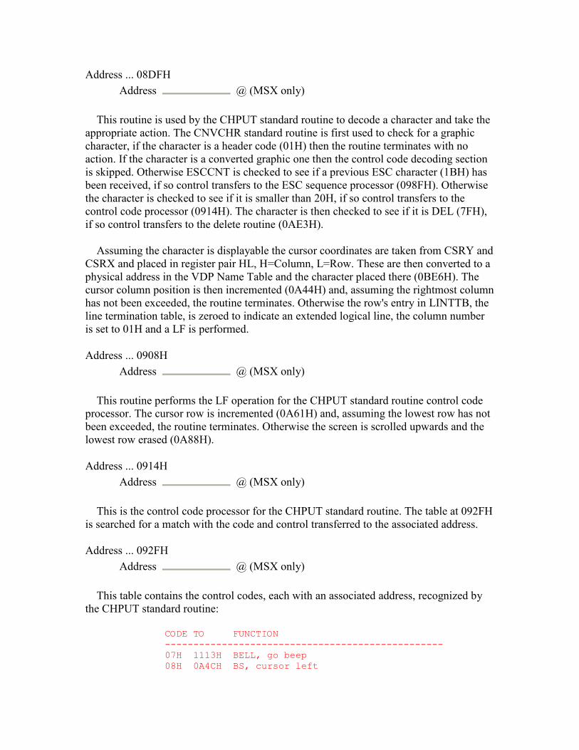
Address ... 08DFH Address @ (MSX only)
This routine is used by the CHPUT standard routine to decode a character and take the appropriate action. The CNVCHR standard routine is first used to check for a graphic character, if the character is a header code (01H) then the routine terminates with no action. If the character is a converted graphic one then the control code decoding section is skipped. Otherwise ESCCNT is checked to see if a previous ESC character (1BH) has been received, if so control transfers to the ESC sequence processor (098FH). Otherwise the character is checked to see if it is smaller than 20H, if so control transfers to the control code processor (0914H). The character is then checked to see if it is DEL (7FH), if so control transfers to the delete routine (0AE3H).
Assuming the character is displayable the cursor coordinates are taken from CSRY and CSRX and placed in register pair HL, H=Column, L=Row. These are then converted to a physical address in the VDP Name Table and the character placed there (0BE6H). The cursor column position is then incremented (0A44H) and, assuming the rightmost column has not been exceeded, the routine terminates. Otherwise the row's entry in LINTTB, the line termination table, is zeroed to indicate an extended logical line, the column number is set to 01H and a LF is performed.
Address ... 0908H Address @ (MSX only)
This routine performs the LF operation for the CHPUT standard routine control code processor. The cursor row is incremented (0A61H) and, assuming the lowest row has not been exceeded, the routine terminates. Otherwise the screen is scrolled upwards and the lowest row erased (0A88H).
Address ... 0914H Address @ (MSX only)
This is the control code processor for the CHPUT standard routine. The table at 092FH is searched for a match with the code and control transferred to the associated address.
Address ... 092FH Address @ (MSX only)
This table contains the control codes, each with an associated address, recognized by the CHPUT standard routine:
CODE TO FUNCTION ------------------------------------------------- 07H 1113H BELL, go beep 08H 0A4CH BS, cursor left
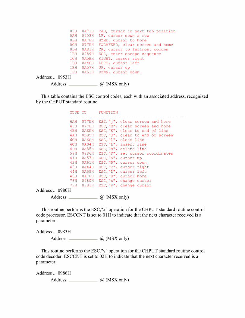
09H 0A71H TAB, cursor to next tab position 0AH 0908H LF, cursor down a row 0BH 0A7FH HOME, cursor to home 0CH 077EH FORMFEED, clear screen and home 0DH 0A81H CR, cursor to leftmost column 1BH 0989H ESC, enter escape sequence 1CH 0A5BH RIGHT, cursor right 1DH 0A4CH LEFT, cursor left 1EH 0A57H UP, cursor up 1FH 0A61H DOWN, cursor down.
Address ... 0953H Address @ (MSX only)
This table contains the ESC control codes, each with an associated address, recognized by the CHPUT standard routine:
CODE TO FUNCTION ------------------------------------------------- 6AH 077EH ESC,"j", clear screen and home 45H 077EH ESC,"E", clear screen and home 4BH 0AEEH ESC,"K", clear to end of line 4AH 0B05H ESC,"J", clear to end of screen 6CH 0AECH ESC,"l", clear line 4CH 0AB4H ESC,"L", insert line 4DH 0A85H ESC,"M", delete line 59H 0986H ESC,"Y", set cursor coordinates 41H 0A57H ESC,"A", cursor up 42H 0A61H ESC,"B", cursor down 43H 0A44H ESC,"C", cursor right 44H 0A55H ESC,"D", cursor left 48H 0A7FH ESC,"H", cursor home 78H 0980H ESC,"x", change cursor 79H 0983H ESC,"y", change cursor
Address ... 0980H Address @ (MSX only)
This routine performs the ESC,"x" operation for the CHPUT standard routine control code processor. ESCCNT is set to 01H to indicate that the next character received is a parameter.
Address ... 0983H Address @ (MSX only)
This routine performs the ESC,"y" operation for the CHPUT standard routine control code decoder. ESCCNT is set to 02H to indicate that the next character received is a parameter.
Address ... 0986H Address @ (MSX only)

This routine performs the ESC",Y" operation for the CHPUT standard routine control code processor. ESCCNT is set to 04H to indicate that the next character received is a parameter.
Address ... 0989H Address @ (MSX only)
This routine performs the ESC operation for the CHPUT standard routine control code processor. ESCCNT is set to FFH to indicate that the next character received is the second control character.
Address ... 098FH Address @ (MSX only)
This is the CHPUT standard routine ESC sequence processor. If ESCCNT contains FFH then the character is the second control character and control transfers to the control code processor (0919H) to search the ESC code table at 0953H.
If ESCCNT contains 01H then the character is the single parameter of the ESC,"x" sequence. If the parameter is "4" (34H) then CSTYLE is set to 00H resulting in a block cursor. If the parameter is "5" (35H) then CSRSW is set to 00H making the cursor normally disabled.
If ESCCNT contains 02H then the character is the single parameter in the ESC,"y" sequence. If the parameter is "4" (34H) then CSTYLE is set to 01H resulting in an underline cursor. If the parameter is "5" (35H) then CSRSW is set to 01H making the cursor normally enabled.
If ESCCNT contains 04H then the character is the first parameter of the ESC,"Y" sequence and is the row coordinate. The parameter has 1FH subtracted and is placed in CSRY, ESCCNT is then decremented to 03H.
If ESCCNT contains 03H then the character is the second parameter of the ESC,"Y" sequence and is the column coordinate. The parameter has 1FH subtracted and is placed in CSRX.
Address ... 09DAH Address @ (MSX only)
This routine is used, by the CHGET standard routine for example, to display the cursor character when it is normally disabled. If CSRSW is non-zero the routine simply terminates with no action, otherwise the cursor is displayed (09E6H).
Address ... 09E1H Address @ (MSX only)
This routine is used, by the CHPUT standard routine for example, to display the cursor character when it is normally enabled. If CSRSW is zero the routine simply terminates with no action. SCRMOD is checked and, if the screen is in Graphics Mode or Multicolour Mode, the routine terminates with no action. Otherwise the cursor coordinates are converted to a physical address in the VDP Name Table and the character read from that location (0BD8H) and saved in CURSAV.
The character's eight byte pixel pattern is read from the VDP Character Pattern Table into the LINWRK buffer (0BA5H). The pixel pattern is then inverted, all eight bytes if CSTYLE indicates a block cursor, only the bottom three if CSTYLE indicates an underline cursor. The pixel pattern is copied back to the position for character code 255 in the VDP Character Pattern Table (0BBEH). The character code 255 is then placed at the current cursor location in the VDP Name Table (0BE6H) and the routine terminates.
This method of generating the cursor character, by using character code 255, can produce curious effects under certain conditions. These can be demonstrated by executing the BASIC statement FOR N=1 TO 100: PRINT CHR$(255);:NEXT and then pressing the cursor up key.
Address ... 0A27H Address @ (MSX only)
This routine is used, by the CHGET standard routine for example, to remove the cursor character when it is normally disabled. If CSRSW is non-zero the routine simply terminates with no action, otherwise the cursor is removed (0A33H).
Address ... 0A2EH Address @ (MSX only)
This routine is used, by the CHPUT standard routine for example, .to remove the cursor character when it is normally enabled. If CSRSW is zero the routine simply terminates with no action. .SCRMOD is checked and, if the screen is in Graphics Mode or Multicolour Mode, the routine terminates with no action. Otherwise the cursor coordinates are converted to a physical address in the VDP Name Table and the character held in CURSAV written to that location (0BE6H).
Address ... 0A44H Address @ (MSX only)
This routine performs the ESC,"C" operation for the CHPUT standard routine control code processor. If the cursor column coordinate is already at the rightmost column, determined by LINLEN, then the routine terminates with no action. Otherwise the column coordinate is incremented and CSRX updated.
Address ... 0A4CH

Address @ (MSX only)
This routine performs the BS/LEFT operation for the CHPUT standard routine control code processor. The cursor column coordinate is decremented and CSRX updated. If the column coordinate has moved beyond the leftmost position it is set to the rightmost position, from LINLEN, and an UP operation performed.
Address ... 0A55H Address @ (MSX only)
This routine performs the ESC,"D" operation for the CHPUT standard routine control code processor. If the cursor column coordinate is already at the leftmost position then the routine terminates with no action. Otherwise the column coordinate is decremented and CSRX updated.
Address ... 0A57H Address @ (MSX only)
This routine performs the ESC,"A" (UP) operation for the CHPUT standard routine control code processor. If the cursor row coordinate is already at the topmost position the routine terminates with no action. Otherwise the row coordinate is decremented and CSRY updated.
Address ... 0A5BH Address @ (MSX only)
This routine performs the RIGHT operation for the CHPUT standard routine control code processor. The cursor column coordinate is incremented and CSRX updated. If the column coordinate has moved beyond the rightmost position, determined by LINLEN, it is set to the leftmost position (01H) and a DOWN operation performed.
Address ... 0A61H Address @ (MSX only)
This routine performs the ESC,"B" (DOWN) operation for the CHPUT standard routine control code processor. If the cursor row coordinate is already at the lowest position, determined by CRTCNT and CNSDFG (0C32H), then the routine terminates with no action. Otherwise the row coordinate is incremented and CSRY updated.
Address ... 0A71H Address @ (MSX only)
This routine performs the TAB operation for the CHPUT standard routine control code processor. ASCII spaces are output (08DFH) until CSRX is a multiple of eight plus one (BIOS columns 1, 9, 17, 25, 33).
Address ... 0A7FH Address @ (MSX only)
This routine performs the ESC,"H" (HOME) operation for the CHPUT standard routine control code processor, CSRX and CSRY are simply set to 1,1. The ROM BIOS cursor coordinate system, while functionally identical to that used by the BASIC Interpreter, numbers the screen rows from 1 to 24 and the columns from 1 to 32/40.
- 47 - 4. ROM BIOS Address ... 0A81H Address @ (MSX only)
This routine performs the CR operation for the CHPUT standard routine control code processor, CSRX is simply set to 01H .
Address ... 0A85H Address @ (MSX only)
This routine performs the ESC,"M" function for the CHPUT standard routine control code processor. A CR operation is first performed to set the cursor column coordinate to the leftmost position. The number of rows from the current row to the bottom of the screen is then determined, if this is zero the current row is simply erased (0AECH). The row count is first used to scroll up the relevant section of LINTTB, the line termination table, by one byte. It is then used to scroll up the relevant section of the screen a row at a time. Starting at the row below the current row, each line is copied from the VDP Name Table into the LINWRK buffer (0BAAH) then copied back to the Name Table one row higher (0BC3H). Finally the lowest row on the screen is erased (0AECH).
Address ... 0AB4H Address @ (MSX only)
This routine performs the ESC,"L" operation for the CHPDT standard routine control code processor. A CR operation is first performed to set the cursor column coordinate to the leftmost position. The number of rows from the current row to the bottom of the screen is then determined, if this is zero the current row is simply erased (0AECH). The row count is first used to scroll down the relevant section of LINTTB, the line termination table, by one byte. It is then used to scroll down the relevant section of the screen a row at a time. Starting at the next to last row of the screen, each line is copied from the VDP Name Table into the LINWRK buffer (0BAAH), then copied back to the Name Table one row lower (0BC3H). Finally the current row is erased (0AECH).
Address ... 0AE3H
Address @ (MSX only)
This routine is used to perform the DEL operation for the CHPUT standard routine control code processor. A LEFT operation is first performed. If this cannot be completed, because the cursor is already at the home position, then the routine terminates with no action. Otherwise a space is written to the VDP Name Table at the cursor's physical location (0BE6H).
Address ... 0AECH Address @ (MSX only)
This routine performs the ESC,"l" operation for the CHPUT standard routine control code processor. The cursor column coordinate is set to 01H and control drops into the ESC,"K" routine.
- 48 - 4. ROM BIOS Address ... 0AEEH Address @ (MSX only)
This routine performs the ESC,"K" operation for the CHPHT standard routine control code processor. The row's entry in LINTTB, the line termination table, is first made non-zero to indicate that the logical line is not extended (0C29H). The cursor coordinates are converted to a physical address (0BF2H) in the VDP Name Table and the VDP set up for writes via the SETWRT standard routine. Spaces are then written directly to the VDP Data Port until the rightmost column, determined by LINLEN, is reached.
Address ... 0B05H Address @ (MSX only)
This routine performs the ESC,"J" operation for the CHPUT standard routine control code processor. An ESC,"K" operation is performed on successive rows, starting with the current one, until the bottom of the screen is reached.
Address ... 0B15H (from 00CCH) Name ...... ERAFNK (Erase Function Keys status bar) Input ..... None Exit ...... None Modifies .. AF, DE, EI
Standard routine to turn the function key display off. CNSDFG is first zeroed and, if the VDP is in Graphics Mode or Multicolour Mode, the routine terminates with no further action. If the VDP is in 40x24 Text Mode or 32x24 Text Mode the last row on the screen is then erased (0AECH).
Address ... 0B26H (from 00C9H) Name ...... FNKSB (Function Key Status Bar) Input ..... None
Exit ...... None Modifies .. AF, BC, DE, EI
Standard routine to show the function key display if it is enabled. If CNSDFG is zero the routine terminates with no action, otherwise control drops into the DSPFNK standard routine..
Address ... 0B2BH (from 00CFH) Name ...... DSPFNK (Display Function Keys status bar) Input ..... None Exit ...... None Modifies .. AF, BC, DE, EI
Standard routine to turn the function key display on. CNSDFG is set to FFH and, if the VDP is in Graphics Mode or Multicolour Mode, the routine terminates with no further action. Otherwise the cursor row coordinate is checked and, if the cursor is on the last row of the screen, a LF code (0AH) issued to the OUTDO standard routine to scroll the screen up.
- 49 - 4. ROM BIOS
Register pair HL is then set to point to either the unshifted or shifted function strings in the Workspace Area depending upon whether the SHIFT key is pressed. LINLEN has four subtracted, to allow a minimum of one space between fields, and is divided by five to determine the field size for each string. Successive characters are then taken from each function string, checked for graphic headers via the CNVCHR standard routine and placed in the LINWRK buffer until the string is exhausted or the zone is filled. When all five strings are completed the LINWRK buffer is written to the last row in the VDP Name Table (0BC3H).
Address ... 0B9CH Address @ (MSX only)
This routine is used by the function key display related standard routines. The contents of register A are placed in CNSDFG then SCRMOD tested and Flag NC returned if the screen is in Graphics Mode or Multicolour Mode.
Address ... 0BA5H Address @ (MSX only)
This routine copies eight bytes from the VDP VRAM into the LINWRK buffer, the VRAM physical address is supplied in register pair HL.
Address ... 0BAAH Address @ (MSX only)
This routine copies a complete row of characters, with the length determined by LINLEN, from the VDP VRAM into the LINWRK buffer. The cursor row coordinate is supplied in register L.
Address ... 0BBEH Address @ (MSX only)
This routine copies eight bytes from the LINWRK buffer into the VDP VRAM, the VRAM physical address is supplied in register pair HL.
Address ... 0BC3H Address @ (MSX only)
This routine copies a complete row of characters, with the length determined by LINLEN, from the LINWRK buffer into the VDP VRAM. The cursor row coordinate is supplied in register L.
Address ... 0BD8H Address @ (MSX only)
This routine reads a single byte from the VDP VRAM into register C. The column coordinate is supplied in register H, the row coordinate in register L.
Address ... 0BE6H Address @ (MSX only)
This routine converts a pair of screen coordinates, the column in register H and the row in register L, into a physical address in the VDP Name Table. This address is returned in register pair HL.
The row coordinate is first multiplied by thirty-two or forty, depending upon the screen mode, and added to the column coordinate. This is then added to the Name Table base address, taken from NAMBAS, to produce an initial address.
Because of the variable screen width, as contained in LINLEN, an additional offset has to be added to the initial address to keep the active region roughly centered within the screen. The difference between the "true" number of characters per row, thirty-two or forty, and the current width is halved and then rounded up to produce the left hand offset. For a UK machine, with a thirty-seven character width in 40x24 Text Mode, this will result in two unused characters on the left hand side and one on the right. The statement PRINT (41-WID)\2, where WID is any screen width, will display the left hand column offset in 40x24 Text Mode.
A complete BASIC program which emulates this routine is given below:
10 CPR=40:NAM=BASE(0):WID=PEEK(&HF3AE) 20 SCRMD=PEEK(&HFCAF):IF SCRMD=0 THEN 40 30 CPR=32:NAM=BASE(5):WID=PEEK(&HF3AF) 40 LH=(CPR+1-WID)\2 50 ADDR=NAM+(ROW-1)*CPR+(COL-1)+LH
This program is designed for the ROW and COL coordinate system used by the ROM BIOS where home is 1,1. Line 50 may be simplified, by removing the "-1" factors, if the BASIC Interpreter's coordinate system is to be used.
Address ... 0C1DH Address @ (MSX only)
This routine calculates the address of a row's entry in LINTTB, the line termination table. The row coordinate is supplied in register L and the address returned in register pair DE.
Address ... 0C29H Address @ (MSX only)
This routine makes a row's entry in LINTTB non-zero when entered at 0C29H and zero when entered at 0C2AH. The row coordinate is supplied in register L.
Address ... 0C32H Address @ (MSX only)
This routine returns the number of rows on the screen in register A. It will normally return twenty-four if the function key display is disabled and twenty-three if it is enabled. Note that the screen size is determined by CRTCNT and may be modified with a BASIC statement, POKE &HF3B1H,14:SCREEN 0 for example.
- 51 - 4. ROM BIOS Address ... 0C3CH (from 0038H) Name ...... KEYINT (Keyboard Interruption handler) Input ..... None Exit ...... None Modifies .. EI
Standard routine to process Z80 interrupts, these are generated by the VDP once every 1/60 s (20 ms on a UK machine). The VDP Status Register is first read and bit 7 checked to ensure that this is a frame rate interrupt, if not the routine terminates with no action. The contents of the Status Register are saved in STATFL and bit 5 checked for sprite coincidence. If the Coincidence Flag is active then the relevant entry in TRPTBL is updated (0EF1H).
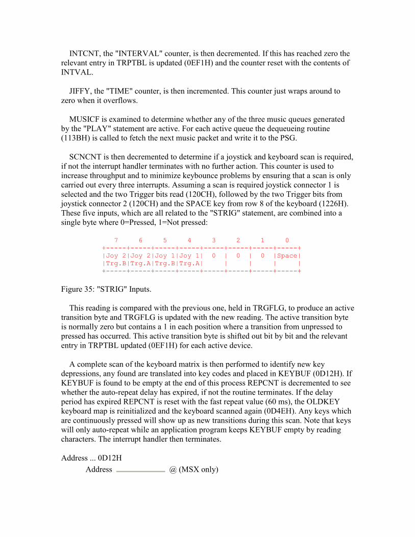
INTCNT, the "INTERVAL" counter, is then decremented. If this has reached zero the relevant entry in TRPTBL is updated (0EF1H) and the counter reset with the contents of INTVAL.
JIFFY, the "TIME" counter, is then incremented. This counter just wraps around to zero when it overflows.
MUSICF is examined to determine whether any of the three music queues generated by the "PLAY" statement are active. For each active queue the dequeueing routine (113BH) is called to fetch the next music packet and write it to the PSG.
SCNCNT is then decremented to determine if a joystick and keyboard scan is required, if not the interrupt handler terminates with no further action. This counter is used to increase throughput and to minimize keybounce problems by ensuring that a scan is only carried out every three interrupts. Assuming a scan is required joystick connector 1 is selected and the two Trigger bits read (120CH), followed by the two Trigger bits from joystick connector 2 (120CH) and the SPACE key from row 8 of the keyboard (1226H). These five inputs, which are all related to the "STRIG" statement, are combined into a single byte where 0=Pressed, 1=Not pressed:
7 6 5 4 3 2 1 0 +-----+-----+-----+-----+-----+-----+-----+-----+ |Joy 2|Joy 2|Joy 1|Joy 1| 0 | 0 | 0 |Space| |Trg.B|Trg.A|Trg.B|Trg.A| | | | | +-----+-----+-----+-----+-----+-----+-----+-----+
Figure 35: "STRIG" Inputs.
This reading is compared with the previous one, held in TRGFLG, to produce an active transition byte and TRGFLG is updated with the new reading. The active transition byte is normally zero but contains a 1 in each position where a transition from unpressed to pressed has occurred. This active transition byte is shifted out bit by bit and the relevant entry in TRPTBL updated (0EF1H) for each active device.
A complete scan of the keyboard matrix is then performed to identify new key depressions, any found are translated into key codes and placed in KEYBUF (0D12H). If KEYBUF is found to be empty at the end of this process REPCNT is decremented to see whether the auto-repeat delay has expired, if not the routine terminates. If the delay period has expired REPCNT is reset with the fast repeat value (60 ms), the OLDKEY keyboard map is reinitialized and the keyboard scanned again (0D4EH). Any keys which are continuously pressed will show up as new transitions during this scan. Note that keys will only auto-repeat while an application program keeps KEYBUF empty by reading characters. The interrupt handler then terminates.
Address ... 0D12H Address @ (MSX only)
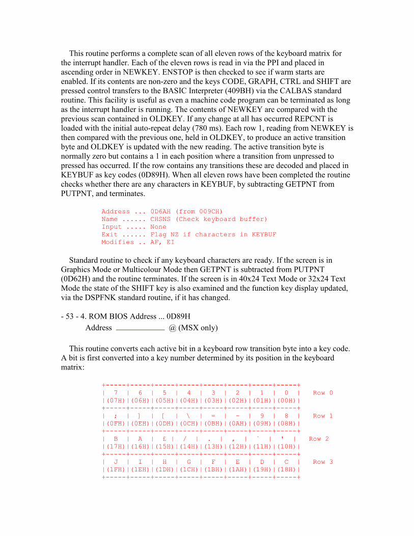
This routine performs a complete scan of all eleven rows of the keyboard matrix for the interrupt handler. Each of the eleven rows is read in via the PPI and placed in ascending order in NEWKEY. ENSTOP is then checked to see if warm starts are enabled. If its contents are non-zero and the keys CODE, GRAPH, CTRL and SHIFT are pressed control transfers to the BASIC Interpreter (409BH) via the CALBAS standard routine. This facility is useful as even a machine code program can be terminated as long as the interrupt handler is running. The contents of NEWKEY are compared with the previous scan contained in OLDKEY. If any change at all has occurred REPCNT is loaded with the initial auto-repeat delay (780 ms). Each row 1, reading from NEWKEY is then compared with the previous one, held in OLDKEY, to produce an active transition byte and OLDKEY is updated with the new reading. The active transition byte is normally zero but contains a 1 in each position where a transition from unpressed to pressed has occurred. If the row contains any transitions these are decoded and placed in KEYBUF as key codes (0D89H). When all eleven rows have been completed the routine checks whether there are any characters in KEYBUF, by subtracting GETPNT from PUTPNT, and terminates.
Address ... 0D6AH (from 009CH) Name ...... CHSNS (Check keyboard buffer) Input ..... None Exit ...... Flag NZ if characters in KEYBUF Modifies .. AF, EI
Standard routine to check if any keyboard characters are ready. If the screen is in Graphics Mode or Multicolour Mode then GETPNT is subtracted from PUTPNT (0D62H) and the routine terminates. If the screen is in 40x24 Text Mode or 32x24 Text Mode the state of the SHIFT key is also examined and the function key display updated, via the DSPFNK standard routine, if it has changed.
- 53 - 4. ROM BIOS Address ... 0D89H Address @ (MSX only)
This routine converts each active bit in a keyboard row transition byte into a key code. A bit is first converted into a key number determined by its position in the keyboard matrix:
+-----+-----+-----+-----+-----+-----+-----+-----+ | 7 | 6 | 5 | 4 | 3 | 2 | 1 | 0 | Row 0 |(07H)|(06H)|(05H)|(04H)|(03H)|(02H)|(01H)|(00H)| +-----+-----+-----+-----+-----+-----+-----+-----+ | ; | ] | [ | \ | = | - | 9 | 8 | Row 1 |(0FH)|(0EH)|(0DH)|(0CH)|(0BH)|(0AH)|(09H)|(08H)| +-----+-----+-----+-----+-----+-----+-----+-----+ | B | A | £ | / | . | , | ` | ' | Row 2 |(17H)|(16H)|(15H)|(14H)|(13H)|(12H)|(11H)|(10H)| +-----+-----+-----+-----+-----+-----+-----+-----+ | J | I | H | G | F | E | D | C | Row 3 |(1FH)|(1EH)|(1DH)|(1CH)|(1BH)|(1AH)|(19H)|(18H)| +-----+-----+-----+-----+-----+-----+-----+-----+
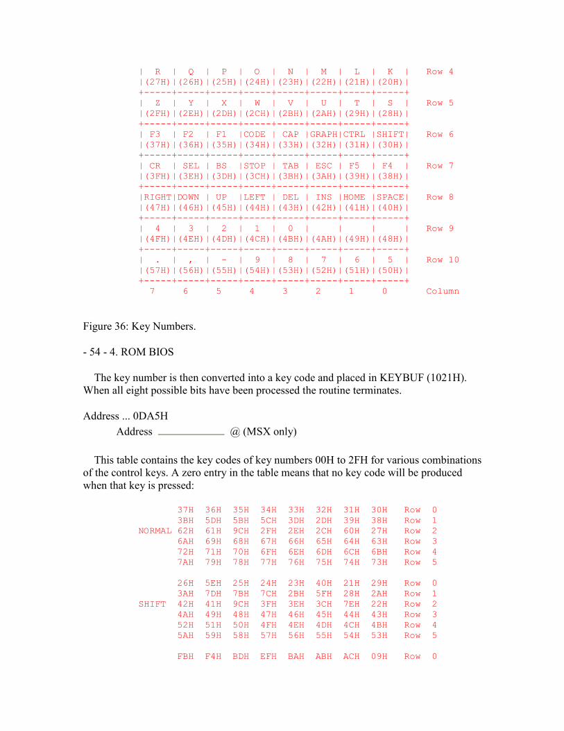
| R | Q | P | O | N | M | L | K | Row 4 |(27H)|(26H)|(25H)|(24H)|(23H)|(22H)|(21H)|(20H)| +-----+-----+-----+-----+-----+-----+-----+-----+ | Z | Y | X | W | V | U | T | S | Row 5 |(2FH)|(2EH)|(2DH)|(2CH)|(2BH)|(2AH)|(29H)|(28H)| +-----+-----+-----+-----+-----+-----+-----+-----+ | F3 | F2 | F1 |CODE | CAP |GRAPH|CTRL |SHIFT| Row 6 |(37H)|(36H)|(35H)|(34H)|(33H)|(32H)|(31H)|(30H)| +-----+-----+-----+-----+-----+-----+-----+-----+ | CR | SEL | BS |STOP | TAB | ESC | F5 | F4 | Row 7 |(3FH)|(3EH)|(3DH)|(3CH)|(3BH)|(3AH)|(39H)|(38H)| +-----+-----+-----+-----+-----+-----+-----+-----+ |RIGHT|DOWN | UP |LEFT | DEL | INS |HOME |SPACE| Row 8 |(47H)|(46H)|(45H)|(44H)|(43H)|(42H)|(41H)|(40H)| +-----+-----+-----+-----+-----+-----+-----+-----+ | 4 | 3 | 2 | 1 | 0 | | | | Row 9 |(4FH)|(4EH)|(4DH)|(4CH)|(4BH)|(4AH)|(49H)|(48H)| +-----+-----+-----+-----+-----+-----+-----+-----+ | . | , | - | 9 | 8 | 7 | 6 | 5 | Row 10 |(57H)|(56H)|(55H)|(54H)|(53H)|(52H)|(51H)|(50H)| +-----+-----+-----+-----+-----+-----+-----+-----+ 7 6 5 4 3 2 1 0 Column
Figure 36: Key Numbers.
- 54 - 4. ROM BIOS
The key number is then converted into a key code and placed in KEYBUF (1021H). When all eight possible bits have been processed the routine terminates.
Address ... 0DA5H Address @ (MSX only)
This table contains the key codes of key numbers 00H to 2FH for various combinations of the control keys. A zero entry in the table means that no key code will be produced when that key is pressed:
37H 36H 35H 34H 33H 32H 31H 30H Row 0 3BH 5DH 5BH 5CH 3DH 2DH 39H 38H Row 1 NORMAL 62H 61H 9CH 2FH 2EH 2CH 60H 27H Row 2 6AH 69H 68H 67H 66H 65H 64H 63H Row 3 72H 71H 70H 6FH 6EH 6DH 6CH 6BH Row 4 7AH 79H 78H 77H 76H 75H 74H 73H Row 5 26H 5EH 25H 24H 23H 40H 21H 29H Row 0 3AH 7DH 7BH 7CH 2BH 5FH 28H 2AH Row 1 SHIFT 42H 41H 9CH 3FH 3EH 3CH 7EH 22H Row 2 4AH 49H 48H 47H 46H 45H 44H 43H Row 3 52H 51H 50H 4FH 4EH 4DH 4CH 4BH Row 4 5AH 59H 58H 57H 56H 55H 54H 53H Row 5 FBH F4H BDH EFH BAH ABH ACH 09H Row 0

06H 0DH 01H 1EH F1H 17H 07H ECH Row 1 GRAPH 11H C4H 9CH 1DH F2H F3H BBH 05H Row 2 C6H DCH 13H 15H 14H CDH C7H BCH Row 3 18H CCH DBH C2H 1BH 0BH C8H DDH Row 4 0FH 19H 1CH CFH 1AH C0H 12H D2H Row 5 00H F5H 00H 00H FCH FDH 00H 0AH Row 0 04H 0EH 02H 16H F0H 1FH 08H 00H Row 1 SHIFT 00H FEH 9CH F6H AFH AEH F7H 03H Row 2 GRAPH CAH DFH D6H 10H D4H CEH C1H FAH Row 3 A9H CBH D7H C3H D3H 0CH C9H DEH Row 4 F8H AAH F9H D0H D5H C5H 00H D1H Row 5 E1H E0H 98H 9BH BFH D9H 9FH EBH Row 0 B7H DAH EDH 9CH E9H EEH 87H E7H Row 1 CODE 97H 84H 9CH A7H A6H 86H E5H B9H Row 2 91H A1H B1H 81H 94H 8CH 8BH 8DH Row 3 93H 83H A3H A2H A4H E6H B5H B3H Row 4 85H A0H 8AH 88H 95H 82H 96H 89H Row 5 00H 00H 9DH 9CH BEH 9EH ADH D8H Row 0 B6H EAH E8H 00H 00H 00H 80H E2H Row 1 SHIFT 00H 8EH 9CH A8H 00H 8FH E4H B8H Row 2 CODE 92H 00H B0H 9AH 99H 00H 00H 00H Row 3 00H 00H E3H 00H A5H 00H B4H B2H Row 4 00H 00H 00H 00H 00H 90H 00H 00H Row 5 7 6 5 4 3 2 1 0 Column
- 55 - 4. ROM BIOS Address ... 0EC5H Address @ (MSX only)
Control transfers to this routine, from 0FC3H, to complete decoding of the five function keys. The relevant entry in FNKFLG is first checked to determine whether the key is associated with an "ON KEY GOSUB" statement. If so, and provided that CURLIN shows the BASIC Interpreter to be in program mode, the relevant entry in TRPTBL is updated (0EF1H) and the routine terminates. If the key is not tied to an "ON KEY GOSUB" statement, or if the Interpreter is in direct mode, the string of characters associated with the function key is returned instead. The key number is multiplied by sixteen, as each string is sixteen characters long, and added to the starting address of the function key strings in the Workspace Area. Sequential characters are then taken from the string and placed in KEYBUF (0F55H) until the zero byte terminator is reached.
Address ... 0EF1H Address @ (MSX only)
This routine is used to update a device's entry in TRPTBL when it has produced a BASIC program interrupt. On entry register pair HL points to the device's status byte in the table. Bit 0 of the status byte is checked first, if the device is not "ON" then the routine terminates with no action. Bit 2, the event flag, is then checked. If this is already set then the routine terminates, otherwise it is set to indicate that an event has occurred. Bit 1, the "STOP" flag, is then checked. If the device is stopped then the routine
terminates with no further action. Otherwise ONGSBF is incremented to signal to the Interpreter Runloop that the event should now be processed.
Address ... 0F06H Address @ (MSX only)
This section of the key decoder processes the HOME key only. The state of the SHIFT key is determined via row 6 of NEWKEY and the key code for HOME (0BH) or CLS (0CH) placed in KEYBUF (0F55H) accordingly.
Address ... 0F10H Address @ (MSX only)
This section of the keyboard decoder processes key numbers 30H to 57H apart from the CAP, F1 to F5, STOP and HOME keys. The key number is simply used to look up the key code in the table at 1033H and this is then placed in KEYBUF (0F55H).
Address ... 0F1FH Address @ (MSX only)
This section of the keyboard decoder processes the DEAD key found on European MSX machines. On UK machines the key in row 2, column 5 always generates the pound key code (9CH) shown in the table at 0DA5H. On European machines this table will have the key code FFH in the same locations. This key code only serves as a flag to indicate that the next key pressed, if it is a vowel, should be modified to produce an accented graphics character.
The state of the SHIFT and CODE keys is determined via row 6 of NEWKEY and one of the following placed in KANAST: 01H=DEAD, 02H=DEAD+SHIFT, 03H=DEAD+CODE, 04H=DEAD+SHIFT+CODE.
Address ... 0F36H Address @ (MSX only)
This section of the keyboard decoder processes the CAP key. The current state of CAPST is inverted and control drops into the CHGCAP standard routine.
Address ... 0F3DH (from 0132H) Name ...... CHGCAP (Change Caps Lock LED) Input ..... A=ON/OFF Switch Exit ...... None Modifies .. AF
Standard routine to turn the Caps Lock LED on or off as determined by the contents of register A: 00H=On, NZ=Off. The LED is modified using the bit set/reset facility of the
PPI Mode Port. As CAPST is not changed this routine does not affect the characters produced by the keyboard.
Address ... 0F46H Address @ (MSX only)
This section of the keyboard decoder processes the STOP key. The state of the CTRL key is determined via row 6 of NEWKEY and the key code for STOP (04H) or CTRL/STOP (03H) produced as appropriate. If the CTRL/STOP code is produced it is copied to INTFLG, for use by the ISCNTC standard routine, and then placed in KEYBUF (0F55H). If the STOP code is produced it is also copied to INTFLG but is not placed in KEYBUF, instead only a click is generated (0F64H). This means that an application program cannot read the STOP key code via the ROM BIOS standard routines.
Address ... 0F55H Address @ (MSX only)
This section of the keyboard decoder places a key code in KEYBUF and generates an audible click. The correct address in the keyboard buffer is first taken from PUTPNT and the code placed there. The address is then incremented (105BH). If it has wrapped round and caught up with GETPNT then the routine terminates with no further action as the keyboard buffer is full. Otherwise PUTPNT is updated with the new address.
CLIKSW and CLIKFL are then both checked to determine whether a click is required. CLIKSW is a general enable/disable switch while CLIKFL is used to prevent multiple clicks when the function keys are pressed. Assuming a click is required the Key Click
output is set via the PPI Mode Port and, after a delay of 50 誑, control drops into the CHGSND standard routine.
- 57 - 4. ROM BIOS Address ... 0F7AH (from 0135H) Name ...... CHGSND (Change keyboard Sound port) Input ..... A=ON/OFF Switch Exit ...... None Modifies .. AF
Standard routine to set or reset the Key Click output via the PPI Mode Port: 00H=Reset, NZ=Set. This audio output is AC coupled so absolute polarities should not be taken too seriously.
Address ... 0F83H Address @ (MSX only)
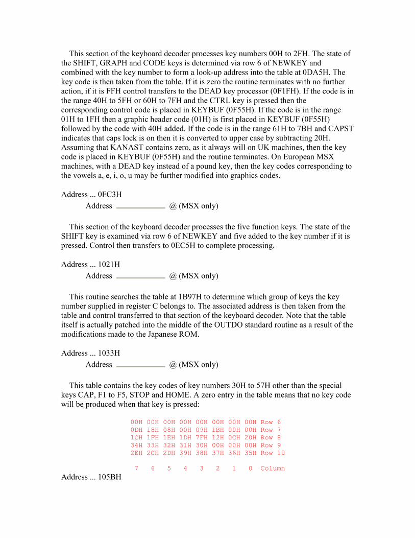
This section of the keyboard decoder processes key numbers 00H to 2FH. The state of the SHIFT, GRAPH and CODE keys is determined via row 6 of NEWKEY and combined with the key number to form a look-up address into the table at 0DA5H. The key code is then taken from the table. If it is zero the routine terminates with no further action, if it is FFH control transfers to the DEAD key processor (0F1FH). If the code is in the range 40H to 5FH or 60H to 7FH and the CTRL key is pressed then the corresponding control code is placed in KEYBUF (0F55H). If the code is in the range 01H to 1FH then a graphic header code (01H) is first placed in KEYBUF (0F55H) followed by the code with 40H added. If the code is in the range 61H to 7BH and CAPST indicates that caps lock is on then it is converted to upper case by subtracting 20H. Assuming that KANAST contains zero, as it always will on UK machines, then the key code is placed in KEYBUF (0F55H) and the routine terminates. On European MSX machines, with a DEAD key instead of a pound key, then the key codes corresponding to the vowels a, e, i, o, u may be further modified into graphics codes.
Address ... 0FC3H Address @ (MSX only)
This section of the keyboard decoder processes the five function keys. The state of the SHIFT key is examined via row 6 of NEWKEY and five added to the key number if it is pressed. Control then transfers to 0EC5H to complete processing.
Address ... 1021H Address @ (MSX only)
This routine searches the table at 1B97H to determine which group of keys the key number supplied in register C belongs to. The associated address is then taken from the table and control transferred to that section of the keyboard decoder. Note that the table itself is actually patched into the middle of the OUTDO standard routine as a result of the modifications made to the Japanese ROM.
Address ... 1033H Address @ (MSX only)
This table contains the key codes of key numbers 30H to 57H other than the special keys CAP, F1 to F5, STOP and HOME. A zero entry in the table means that no key code will be produced when that key is pressed:
00H 00H 00H 00H 00H 00H 00H 00H Row 6 0DH 18H 08H 00H 09H 1BH 00H 00H Row 7 1CH 1FH 1EH 1DH 7FH 12H 0CH 20H Row 8 34H 33H 32H 31H 30H 00H 00H 00H Row 9 2EH 2CH 2DH 39H 38H 37H 36H 35H Row 10 7 6 5 4 3 2 1 0 Column
Address ... 105BH

Address @ (MSX only)
This routine simply zeroes KANAST and then transfers control to 10C2H.
Address ... 1061H Address @ (MSX only)
This table contains the graphics characters which replace the vowels a, e, i, o, u on European machines.
Address ... 10C2H Address @ (MSX only)
This routine increments the keyboard buffer pointer, either PUTPNT or GETPNT, supplied in register pair HL. If the pointer then exceeds the end of the keyboard buffer it is wrapped back to the beginning.
Address ... 10CBH (from 009FH) Name ...... CHGET (Character Get) Input ..... None Exit ...... A=Character from keyboard Modifies .. AF, EI
Standard routine to fetch a character from the keyboard buffer. The buffer is first checked to see if already contains a character (0D6AH). If not the cursor is turned on (09DAH), the buffer checked repeatedly until a character appears (0D6AH) and then the cursor turned off (0A27H). The character is taken from the buffer using GETPNT which is then incremented (10C2H).
Address ... 10F9H (from 00BDH) Name ...... CKCNTC (Check Control-stop) Input ..... None Exit ...... None Modifies .. AF, EI
Standard routine to check whether the CTRL-STOP or STOP keys have been pressed. It is used by the BASIC Interpreter inside processor-intensive statements, such as "WAIT" and "CIRCLE", to check for program termination. Register pair HL is first zeroed and then control transferred to the ISCNTC standard routine. When the Interpreter is running register pair HL normally contains the address of the current character in the BASIC program text. If ISCNTC is CTRL-STOP terminated this address will be placed in OLDTXT by the "STOP" statement handler (63E6H) for use by a later "CONT" statement. Zeroing register pair HL beforehand signals to the "CONT" handler that termination occurred inside a statement and it will issue a "Can't CONTINUE" error if continuation is attempted.
Address ... 1102H (from 0093H)
Name ...... WRTPSG (Write to PSG register) Input ..... A=Register number, E=Data byte Exit ...... None Modifies .. EI
Standard routine to write a data byte to any of the sixteen PSG registers. The register selection number is written to the PSG Address Port and the data byte written to the PSG Data Write Port.
Address ... 110EH (from 0096H) Name ...... RDPSG (Read from PSG register) Input ..... A=Register number Exit ...... A=Data byte read from PSG Modifies .. A
Standard routine to read a data byte from any of the sixteen PSG registers. The register selection number is written to the PSG Address Port and the data byte read from the PSG Data Read Port.
Address ... 1113H (from 00C0H) Name ...... BEEP (Beep) Input ..... None Exit ...... None Modifies .. AF, BC, E, EI
Standard routine to produce a beep via the PSG. Channel A is set to produce a tone of 1316 Hz then enabled with an amplitude of seven. After a delay of 40 ms control transfers to the GICINI standard routine to reinitialize the PSG.
Address ... 113BH Address @ (MSX only)
This routine is used by the interrupt handler to service a music queue. As there are three of these, each feeding a PSG channel, the queue to be serviced is specified by supplying its number in register A: 0=VOICAQ, 1=VOICBQ and 2=VOICCQ.
Each string in a "PLAY" statement is translated into a series of data packets by the BASIC Interpreter. These are placed in the appropriate queue followed by an end of data byte (FFH). The task of dequeueing the packets, decoding them and setting the PSG is left to the interrupt handler. The Interpreter is thus free to proceed immediately to the next statement without having to wait for notes to finish.
- 60 - 4. ROM BIOS
The first two bytes of any packet specify its byte count and duration. The three most significant bits of the first byte specify the number of bytes following the header in the packet. The remainder of the header specifies the event duration in 1/60 s units (20 ms in
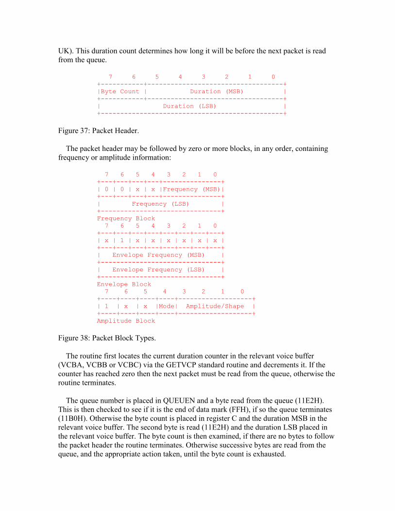
UK). This duration count determines how long it will be before the next packet is read from the queue.
7 6 5 4 3 2 1 0 +-----------+-----------------------------------+ |Byte Count | Duration (MSB) | +-----------+-----------------------------------+ | Duration (LSB) | +-----------------------------------------------+
Figure 37: Packet Header.
The packet header may be followed by zero or more blocks, in any order, containing frequency or amplitude information:
7 6 5 4 3 2 1 0 +---+---+---+---+---------------+ | 0 | 0 | x | x |Frequency (MSB)| +---+---+---+---+---------------+ | Frequency (LSB) | +-------------------------------+ Frequency Block 7 6 5 4 3 2 1 0 +---+---+---+---+---+---+---+---+ | x | 1 | x | x | x | x | x | x | +---+---+---+---+---+---+---+---+ | Envelope Frequency (MSB) | +-------------------------------+ | Envelope Frequency (LSB) | +-------------------------------+ Envelope Block 7 6 5 4 3 2 1 0 +----+----+----+----+-------------------+ | 1 | x | x |Mode| Amplitude/Shape | +----+----+----+----+-------------------+ Amplitude Block
Figure 38: Packet Block Types.
The routine first locates the current duration counter in the relevant voice buffer (VCBA, VCBB or VCBC) via the GETVCP standard routine and decrements it. If the counter has reached zero then the next packet must be read from the queue, otherwise the routine terminates.
The queue number is placed in QUEUEN and a byte read from the queue (11E2H). This is then checked to see if it is the end of data mark (FFH), if so the queue terminates (11B0H). Otherwise the byte count is placed in register C and the duration MSB in the relevant voice buffer. The second byte is read (11E2H) and the duration LSB placed in the relevant voice buffer. The byte count is then examined, if there are no bytes to follow the packet header the routine terminates. Otherwise successive bytes are read from the queue, and the appropriate action taken, until the byte count is exhausted.

If a frequency block is found then a second byte is read and both bytes written to PSG Registers 0 and 1, 2 and 3 or 4 and 5 depending on the queue number.
If an amplitude block is found the Amplitude and Mode bits are written to PSG Registers 8, 9 or 10 depending on the queue number. If the Mode bit is 1, selecting modulated rather than fixed amplitude, then the byte is also written to PSG Register 13 to set the envelope shape.
If an envelope block is found, or if bit 6 of an amplitude block is set, then a further two bytes are read from the queue and written to PSG Registers 11 and 12.
Address ... 11B0H Address @ (MSX only)
This routine is used when an end of data mark (FFH) is found in one of the three music queues. An amplitude value of zero is written to PSG Register 8 9 or 10, depending on the queue number, to shut the channel down. The channel's bit in MUSICF is then reset and control drops into the STRTMS standard routine.
Address ... 11C4H (from 0099H) Name ...... STRTMS (Start Music) Input ..... None Exit ...... None Modifies .. AF, HL
Standard routine used by the "PLAY" statement handler to initiate music dequeueing by the interrupt handler. MUSICF is first examined, if any channels are already running the routine terminates with no action. PLYCNT is then decremented, if there are no more "PLAY" strings queued up the routine terminates. Otherwise the three duration counters, in VCBA, VCBB and VCBC, are set to 0001H, so that the first packet of the new group will be dequeued at the next interrupt, and MUSICF is set to 07H to enable all three channels.
- 62 - 4. ROM BIOS Address ... 11E2H Address @ (MSX only)
This routine loads register A with the current queue number, from QUEUEN, and then reads a byte from that queue (14ADH).
Address ... 11EEH (from 00D5H) Name ...... GTSTCK (Get joyStick status) Input ..... A=Joystick ID (0, 1 or 2) Exit ...... A=Joystick position code Modifies .. AF, B, DE, HL, EI
Standard routine to read the position of a joystick or the four cursor keys. If the supplied ID is zero the state of the cursor keys is read via PPI Port B (1226H) and

converted to a position code using the look-up table at 1243H. Otherwise joystick connector 1 or 2 is read (120CH) and the four direction bits converted to a position code using the look-up table at 1233H. The returned position codes are:
1 8 | 2 \ | / \|/ 7----0----3 /|\ / | \ 6 | 4 5
Address ... 120CH Address @ (MSX only)
This routine reads the joystick connector specified by the contents of register A: 0=Connector 1, 1=Connector 2. The current contents of PSG Register 15 are read in then written back with the Joystick Select bit appropriately set. PSG Register 14 is then read into register A (110CH) and the routine terminates.
Address ... 1226H Address @ (MSX only)
This routine reads row 8 of the keyboard matrix. The current contents of PPI Port C are read in then written back with the four Keyboard Row Select bits set for row 8. The column inputs are then read into register A from PPI Port B.
Address ... 1253H (from 00D8H) Name ...... GTTRIG (Get Trigget status) Input ..... A=Trigger ID (0, 1, 2, 3 or 4) Exit ...... A=Status code Modifies .. AF, BC, EI
Standard routine to check the joystick trigger or space key status. If the supplied ID is zero row 8 of the keyboard matrix is read (1226H) and converted to a status code. Otherwise joystick connector 1 or 2 is read (120CH) and converted to a status code. The selection IDs are:
0=SPACE KEY 1=JOY 1, TRIGGER A 2=JOY 2, TRIGGER A 3=JOY 1, TRIGGER B 4=JOY 2, TRIGGER B
The value returned is FFH if the relevant trigger is pressed and zero otherwise.
Address ... 1273H (from 00DEH) Name ...... GTPDL (Get Paddle status)
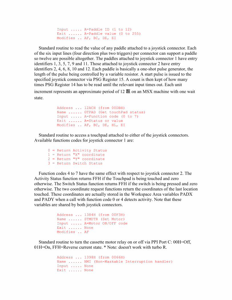
Input ..... A=Paddle ID (1 to 12) Exit ...... A=Paddle value (0 to 255) Modifies .. AF, BC, DE, EI
Standard routine to read the value of any paddle attached to a joystick connector. Each of the six input lines (four direction plus two triggers) per connector can support a paddle so twelve are possible altogether. The paddles attached to joystick connector 1 have entry identifiers 1, 3, 5, 7, 9 and 11. Those attached to joystick connector 2 have entry identifiers 2, 4, 6, 8, 10 and 12. Each paddle is basically a one-shot pulse generator, the length of the pulse being controlled by a variable resistor. A start pulse is issued to the specified joystick connector via PSG Register 15. A count is then kept of how many times PSG Register 14 has to be read until the relevant input times out. Each unit
increment represents an approximate period of 12 誑 on an MSX machine with one wait state.
Address ... 12ACH (from 00DBH) Name ...... GTPAD (Get touchPad status) Input ..... A=Function code (0 to 7) Exit ...... A=Status or value Modifies .. AF, BC, DE, HL, EI
Standard routine to access a touchpad attached to either of the joystick connectors. Available functions codes for joystick connector 1 are:
0 = Return Activity Status 1 = Return "X" coordinate 2 = Return "Y" coordinate 3 = Return Switch Status
Function codes 4 to 7 have the same effect with respect to joystick connector 2. The Activity Status function returns FFH if the Touchpad is being touched and zero otherwise. The Switch Status function returns FFH if the switch is being pressed and zero otherwise. The two coordinate request functions return the coordinates of the last location touched. These coordinates are actually stored in the Workspace Area variables PADX and PADY when a call with function code 0 or 4 detects activity. Note that these variables are shared by both joystick connectors.
Address ... 1384H (from 00F3H) Name ...... STMOTR (Set Motor) Input ..... A=Motor ON/OFF code Exit ...... None Modifies .. AF
Standard routine to turn the cassette motor relay on or off via PPI Port C: 00H=Off, 01H=On, FFH=Reverse current state. * Note: doesn't work with turbo R.
Address ... 1398H (from 0066H) Name ...... NMI (Non-Maskable Interruption handler) Input ..... None Exit ...... None
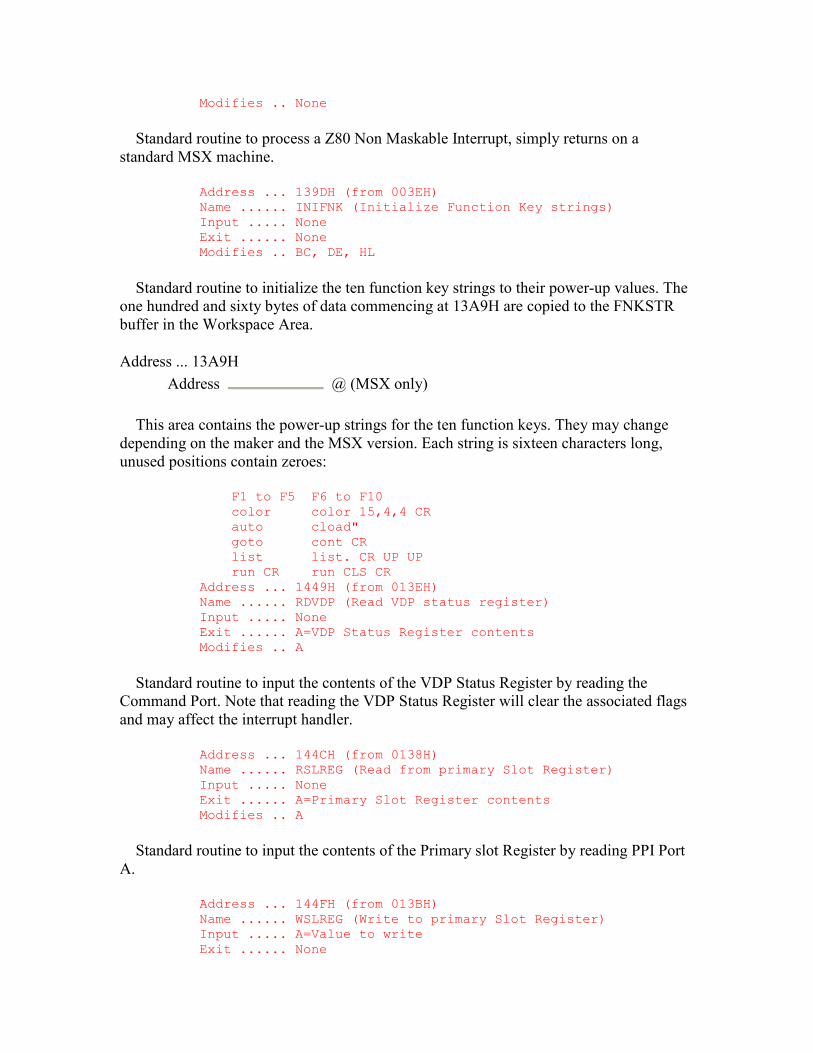
Modifies .. None
Standard routine to process a Z80 Non Maskable Interrupt, simply returns on a standard MSX machine.
Address ... 139DH (from 003EH) Name ...... INIFNK (Initialize Function Key strings) Input ..... None Exit ...... None Modifies .. BC, DE, HL
Standard routine to initialize the ten function key strings to their power-up values. The one hundred and sixty bytes of data commencing at 13A9H are copied to the FNKSTR buffer in the Workspace Area.
Address ... 13A9H Address @ (MSX only)
This area contains the power-up strings for the ten function keys. They may change depending on the maker and the MSX version. Each string is sixteen characters long, unused positions contain zeroes:
F1 to F5 F6 to F10 color color 15,4,4 CR auto cload" goto cont CR list list. CR UP UP run CR run CLS CR Address ... 1449H (from 013EH) Name ...... RDVDP (Read VDP status register) Input ..... None Exit ...... A=VDP Status Register contents Modifies .. A
Standard routine to input the contents of the VDP Status Register by reading the Command Port. Note that reading the VDP Status Register will clear the associated flags and may affect the interrupt handler.
Address ... 144CH (from 0138H) Name ...... RSLREG (Read from primary Slot Register) Input ..... None Exit ...... A=Primary Slot Register contents Modifies .. A
Standard routine to input the contents of the Primary slot Register by reading PPI Port A.
Address ... 144FH (from 013BH) Name ...... WSLREG (Write to primary Slot Register) Input ..... A=Value to write Exit ...... None
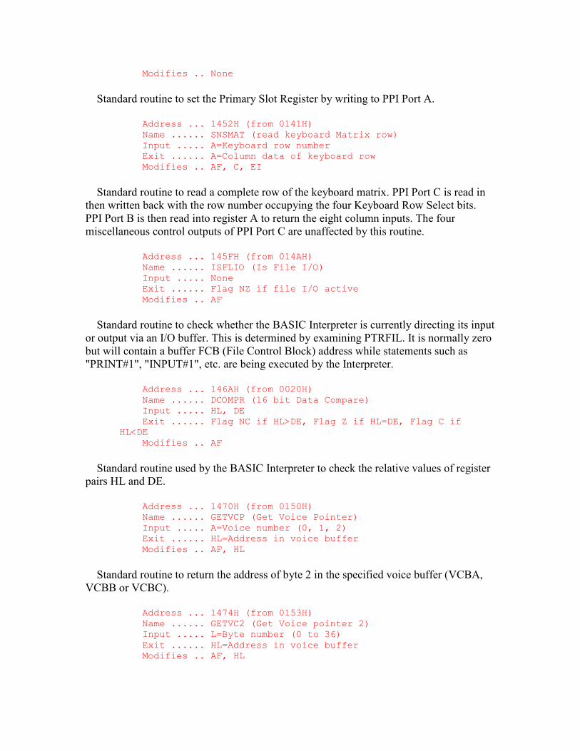
Modifies .. None
Standard routine to set the Primary Slot Register by writing to PPI Port A.
Address ... 1452H (from 0141H) Name ...... SNSMAT (read keyboard Matrix row) Input ..... A=Keyboard row number Exit ...... A=Column data of keyboard row Modifies .. AF, C, EI
Standard routine to read a complete row of the keyboard matrix. PPI Port C is read in then written back with the row number occupying the four Keyboard Row Select bits. PPI Port B is then read into register A to return the eight column inputs. The four miscellaneous control outputs of PPI Port C are unaffected by this routine.
Address ... 145FH (from 014AH) Name ...... ISFLIO (Is File I/O) Input ..... None Exit ...... Flag NZ if file I/O active Modifies .. AF
Standard routine to check whether the BASIC Interpreter is currently directing its input or output via an I/O buffer. This is determined by examining PTRFIL. It is normally zero but will contain a buffer FCB (File Control Block) address while statements such as "PRINT#1", "INPUT#1", etc. are being executed by the Interpreter.
Address ... 146AH (from 0020H) Name ...... DCOMPR (16 bit Data Compare) Input ..... HL, DE Exit ...... Flag NC if HL>DE, Flag Z if HL=DE, Flag C if HL<DE Modifies .. AF
Standard routine used by the BASIC Interpreter to check the relative values of register pairs HL and DE.
Address ... 1470H (from 0150H) Name ...... GETVCP (Get Voice Pointer) Input ..... A=Voice number (0, 1, 2) Exit ...... HL=Address in voice buffer Modifies .. AF, HL
Standard routine to return the address of byte 2 in the specified voice buffer (VCBA, VCBB or VCBC).
Address ... 1474H (from 0153H) Name ...... GETVC2 (Get Voice pointer 2) Input ..... L=Byte number (0 to 36) Exit ...... HL=Address in voice buffer Modifies .. AF, HL

Standard routine to return the address of any byte in the voice buffer (VCBA, VCBB or VCBC) specified by the voice number in VOICEN.
Address ... 148AH (from 0144H) Name ...... PHYDIO (Physical Disk I/O access) Input ..... None Exit ...... None Modifies .. None
Standard routine for use by Disk BASIC, simply returns on standard MSX machines.
Address ... 148EH (from 0147H) Name ...... FORMAT (Format disk) Input ..... None Exit ...... None Modifies .. None
Standard routine for use by Disk BASIC, simply returns on standard MSX machines.
Address ... 1492H (from 00F9H) Name ...... PUTQ (Put byte in Queue) Input ..... A=Queue number, E=Data byte Exit ...... Flag Z if queue full Modifies .. AF, BC, HL
Standard routine to place a data byte in one of the three music queues. The queue's get and put positions are first taken from QUETAB (14FAH). The put position is temporarily incremented and compared with the get position, if they are equal the routine terminates as the queue is full. Otherwise the queue's address is taken from QUETAB and the put position added to it. The data byte is placed at this location in the queue, the put position is incremented and the routine terminates. Note that the music queues are circular, if the get or put pointers reach the last position in the queue they wrap around back to the start.
Address ... 14ADH Address @ (MSX only)
This routine is used by the interrupt handler to read a byte from one of the three music queues. The queue number is supplied in register A, the data byte is returned in register A and the routine returns Flag Z if the queue is empty. The queue's get and put positions are first taken from QUETAB (14FAH). If the putback flag is active then the data byte is taken from QUEBAK and the routine terminates (14D1H), this facility is unused in the current versions of the MSX ROM. The put position is then compared with the get position, if they are equal the routine terminates as the queue is empty. Otherwise the queue's address is taken from QUETAB and the get position added to it. The data byte is read from this location in the queue, the get position is incremented and the routine terminates.
Address ... 14DAH
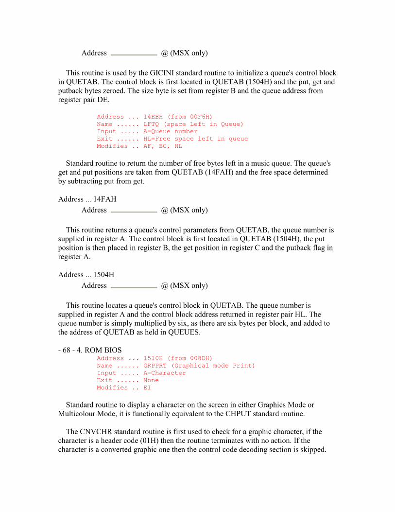
Address @ (MSX only)
This routine is used by the GICINI standard routine to initialize a queue's control block in QUETAB. The control block is first located in QUETAB (1504H) and the put, get and putback bytes zeroed. The size byte is set from register B and the queue address from register pair DE.
Address ... 14EBH (from 00F6H) Name ...... LFTQ (space Left in Queue) Input ..... A=Queue number Exit ...... HL=Free space left in queue Modifies .. AF, BC, HL
Standard routine to return the number of free bytes left in a music queue. The queue's get and put positions are taken from QUETAB (14FAH) and the free space determined by subtracting put from get.
Address ... 14FAH Address @ (MSX only)
This routine returns a queue's control parameters from QUETAB, the queue number is supplied in register A. The control block is first located in QUETAB (1504H), the put position is then placed in register B, the get position in register C and the putback flag in register A.
Address ... 1504H Address @ (MSX only)
This routine locates a queue's control block in QUETAB. The queue number is supplied in register A and the control block address returned in register pair HL. The queue number is simply multiplied by six, as there are six bytes per block, and added to the address of QUETAB as held in QUEUES.
- 68 - 4. ROM BIOS Address ... 1510H (from 008DH) Name ...... GRPPRT (Graphical mode Print) Input ..... A=Character Exit ...... None Modifies .. EI
Standard routine to display a character on the screen in either Graphics Mode or Multicolour Mode, it is functionally equivalent to the CHPUT standard routine.
The CNVCHR standard routine is first used to check for a graphic character, if the character is a header code (01H) then the routine terminates with no action. If the character is a converted graphic one then the control code decoding section is skipped.

Otherwise the character is checked to see if it is a control code. Only the CR code (0DH) is recognized (157EH), all other characters smaller than 20H are ignored.
Assuming the character is displayable its eight byte pixel pattern is copied from the ROM character set into the PATWRK buffer (0752H) and FORCLR copied to ATRBYT to set its colour. The current graphics coordinates are then taken from GRPACX and GRPACY and used to set the current pixel physical address via the SCALXY and MAPXYC standard routines.
The eight byte pattern in PATWRK is processed a byte at a time. At the start of each byte the current pixel physical address is obtained via the FETCHC standard routine and saved. The eight bits are then examined in turn. If the bit is a 1 the associated pixel is set by the SETC standard routine, if it is a 0 no action is taken. After each bit the current pixel physical address is moved right (16ACH). When the byte is finished, or the right hand edge of the screen is reached, the initial current pixel physical address is restored and moved down one position by the TDOWNC standard routine.
When the pattern is complete, or the bottom of the screen has been reached, GRPACX is updated. In Graphics Mode its value is increased by eight, in Multicolour Mode by thirty-two. If GRPACX then exceeds 255, the right hand edge of the screen, a CR operation is performed (157EH).
Address ... 157EH Address @ (MSX only)
This routine performs the CR operation for the GRPPRT standard routine, this code functions as a combined CR,LF. GRPACX is zeroed and eight or thirty-two, depending on the screen mode, added to GRPACY. If GRPACY then exceeds 191, the bottom of the screen, it is set to zero.
GRPACX and GRPACY may be manipulated directly by an application program to compensate for the limited number of control functions available.
- 69 - 4. ROM BIOS Address ... 1599H (from 010EH) Name ...... SCALXY (Scale (X,Y) coordinates) Input ..... BC=X coordinate, DE=Y coordinate Exit ...... Flag NC if clipped Modifies .. AF
Standard routine to clip a pair of graphics coordinates if necessary. The BASIC Interpreter can produce coordinates in the range -32768 to +32767 even though this far exceeds the actual screen size. This routine modifies excessive coordinate values to fit within the physically realizable range. If the X coordinate is greater than 255 it is set to 255, if the Y coordinate is greater than 191 it is set to 191. If either coordinate is negative (greater than 7FFFH) it is set to zero. Finally if the screen is in Multicolour Mode both coordinates are divided by four as required by the MAPXYC standard routine.
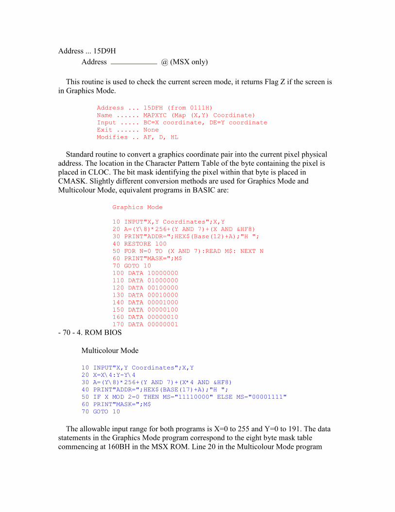
Address ... 15D9H Address @ (MSX only)
This routine is used to check the current screen mode, it returns Flag Z if the screen is in Graphics Mode.
Address ... 15DFH (from 0111H) Name ...... MAPXYC (Map (X,Y) Coordinate) Input ..... BC=X coordinate, DE=Y coordinate Exit ...... None Modifies .. AF, D, HL
Standard routine to convert a graphics coordinate pair into the current pixel physical address. The location in the Character Pattern Table of the byte containing the pixel is placed in CLOC. The bit mask identifying the pixel within that byte is placed in CMASK. Slightly different conversion methods are used for Graphics Mode and Multicolour Mode, equivalent programs in BASIC are:
Graphics Mode 10 INPUT"X,Y Coordinates";X,Y 20 A=(Y\8)*256+(Y AND 7)+(X AND &HF8) 30 PRINT"ADDR=";HEX$(Base(12)+A);"H "; 40 RESTORE 100 50 FOR N=0 TO (X AND 7):READ M$: NEXT N 60 PRINT"MASK=";M$ 70 GOTO 10 100 DATA 10000000 110 DATA 01000000 120 DATA 00100000 130 DATA 00010000 140 DATA 00001000 150 DATA 00000100 160 DATA 00000010 170 DATA 00000001
- 70 - 4. ROM BIOS
Multicolour Mode
10 INPUT"X,Y Coordinates";X,Y 20 X=X\4:Y-Y\4 30 A=(Y\8)*256+(Y AND 7)+(X*4 AND &HF8) 40 PRINT"ADDR=";HEX$(BASE(17)+A);"H "; 50 IF X MOD 2=0 THEN MS="11110000" ELSE MS="00001111" 60 PRINT"MASK=";M$ 70 GOTO 10
The allowable input range for both programs is X=0 to 255 and Y=0 to 191. The data statements in the Graphics Mode program correspond to the eight byte mask table commencing at 160BH in the MSX ROM. Line 20 in the Multicolour Mode program
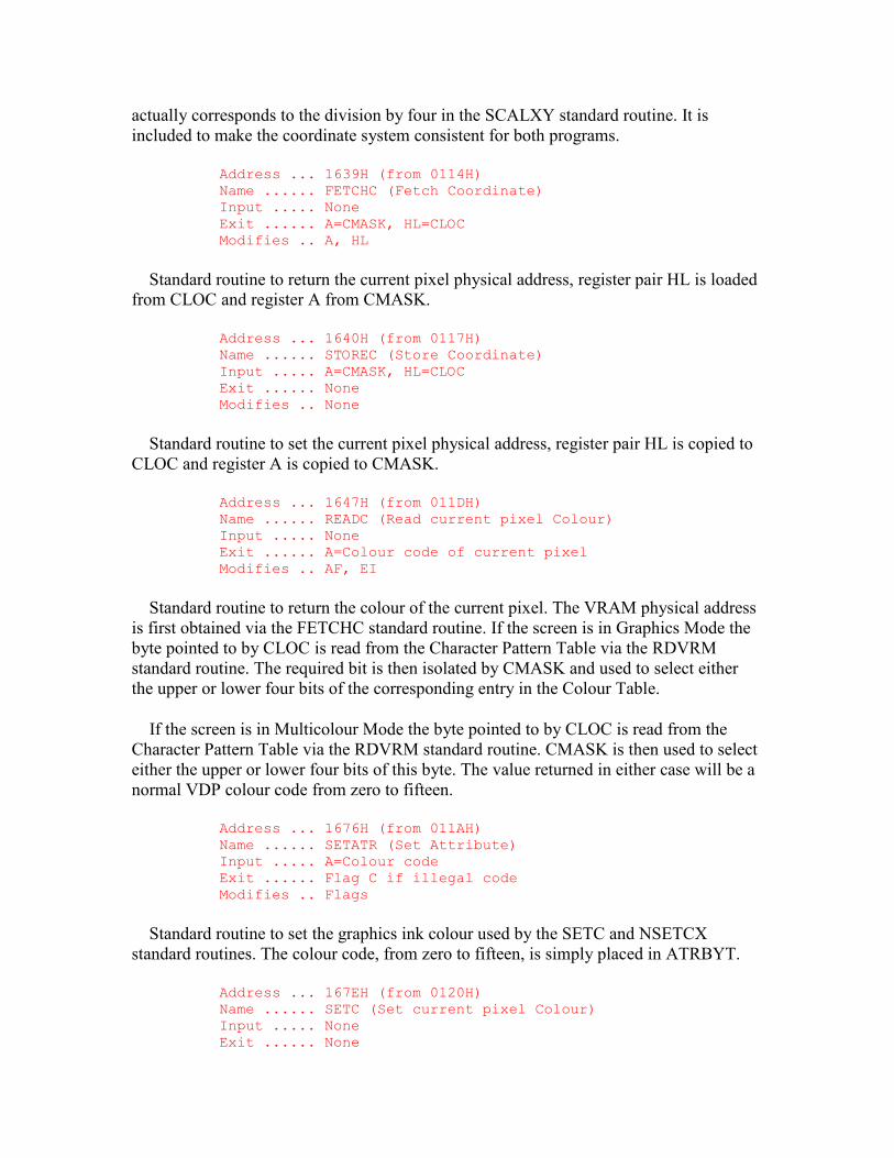
actually corresponds to the division by four in the SCALXY standard routine. It is included to make the coordinate system consistent for both programs.
Address ... 1639H (from 0114H) Name ...... FETCHC (Fetch Coordinate) Input ..... None Exit ...... A=CMASK, HL=CLOC Modifies .. A, HL
Standard routine to return the current pixel physical address, register pair HL is loaded from CLOC and register A from CMASK.
Address ... 1640H (from 0117H) Name ...... STOREC (Store Coordinate) Input ..... A=CMASK, HL=CLOC Exit ...... None Modifies .. None
Standard routine to set the current pixel physical address, register pair HL is copied to CLOC and register A is copied to CMASK.
Address ... 1647H (from 011DH) Name ...... READC (Read current pixel Colour) Input ..... None Exit ...... A=Colour code of current pixel Modifies .. AF, EI
Standard routine to return the colour of the current pixel. The VRAM physical address is first obtained via the FETCHC standard routine. If the screen is in Graphics Mode the byte pointed to by CLOC is read from the Character Pattern Table via the RDVRM standard routine. The required bit is then isolated by CMASK and used to select either the upper or lower four bits of the corresponding entry in the Colour Table.
If the screen is in Multicolour Mode the byte pointed to by CLOC is read from the Character Pattern Table via the RDVRM standard routine. CMASK is then used to select either the upper or lower four bits of this byte. The value returned in either case will be a normal VDP colour code from zero to fifteen.
Address ... 1676H (from 011AH) Name ...... SETATR (Set Attribute) Input ..... A=Colour code Exit ...... Flag C if illegal code Modifies .. Flags
Standard routine to set the graphics ink colour used by the SETC and NSETCX standard routines. The colour code, from zero to fifteen, is simply placed in ATRBYT.
Address ... 167EH (from 0120H) Name ...... SETC (Set current pixel Colour) Input ..... None Exit ...... None
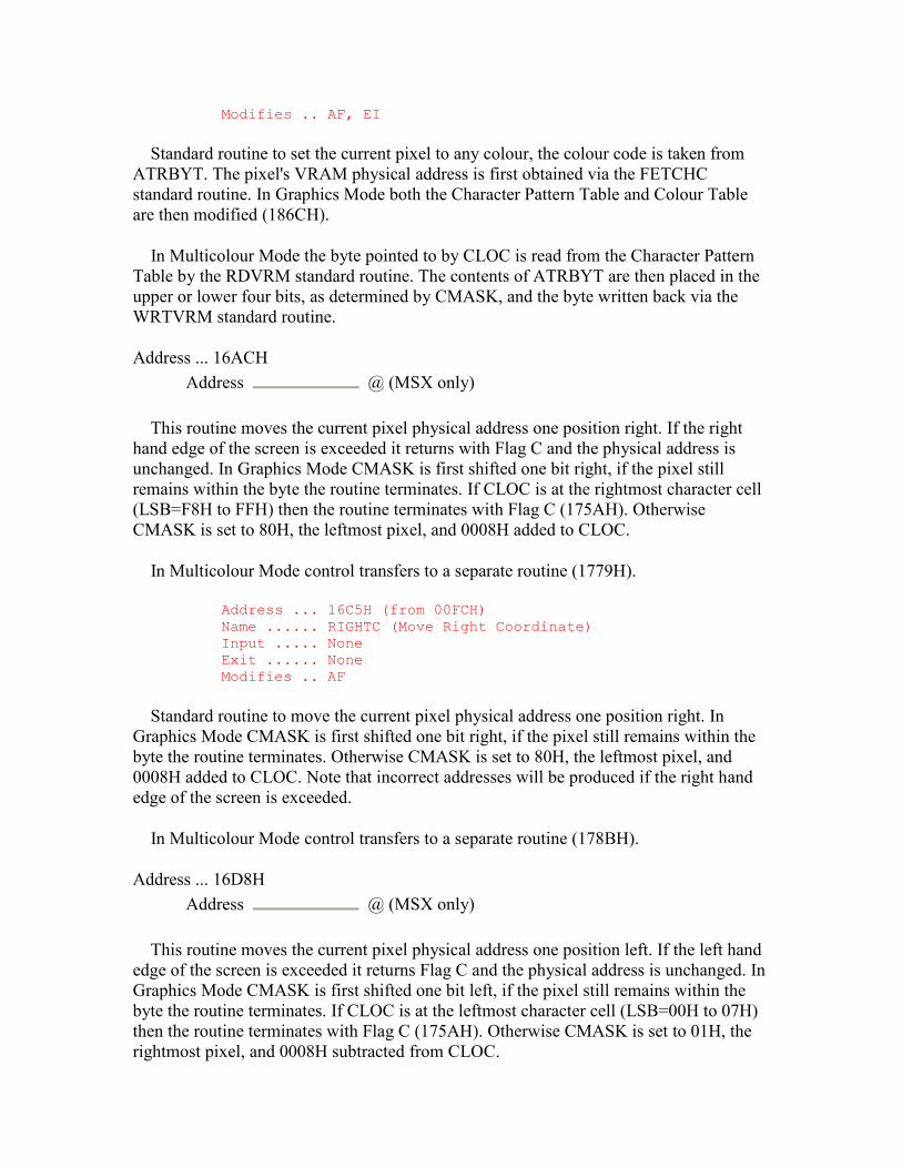
Modifies .. AF, EI
Standard routine to set the current pixel to any colour, the colour code is taken from ATRBYT. The pixel's VRAM physical address is first obtained via the FETCHC standard routine. In Graphics Mode both the Character Pattern Table and Colour Table are then modified (186CH).
In Multicolour Mode the byte pointed to by CLOC is read from the Character Pattern Table by the RDVRM standard routine. The contents of ATRBYT are then placed in the upper or lower four bits, as determined by CMASK, and the byte written back via the WRTVRM standard routine.
Address ... 16ACH Address @ (MSX only)
This routine moves the current pixel physical address one position right. If the right hand edge of the screen is exceeded it returns with Flag C and the physical address is unchanged. In Graphics Mode CMASK is first shifted one bit right, if the pixel still remains within the byte the routine terminates. If CLOC is at the rightmost character cell (LSB=F8H to FFH) then the routine terminates with Flag C (175AH). Otherwise CMASK is set to 80H, the leftmost pixel, and 0008H added to CLOC.
In Multicolour Mode control transfers to a separate routine (1779H).
Address ... 16C5H (from 00FCH) Name ...... RIGHTC (Move Right Coordinate) Input ..... None Exit ...... None Modifies .. AF
Standard routine to move the current pixel physical address one position right. In Graphics Mode CMASK is first shifted one bit right, if the pixel still remains within the byte the routine terminates. Otherwise CMASK is set to 80H, the leftmost pixel, and 0008H added to CLOC. Note that incorrect addresses will be produced if the right hand edge of the screen is exceeded.
In Multicolour Mode control transfers to a separate routine (178BH).
Address ... 16D8H Address @ (MSX only)
This routine moves the current pixel physical address one position left. If the left hand edge of the screen is exceeded it returns Flag C and the physical address is unchanged. In Graphics Mode CMASK is first shifted one bit left, if the pixel still remains within the byte the routine terminates. If CLOC is at the leftmost character cell (LSB=00H to 07H) then the routine terminates with Flag C (175AH). Otherwise CMASK is set to 01H, the rightmost pixel, and 0008H subtracted from CLOC.
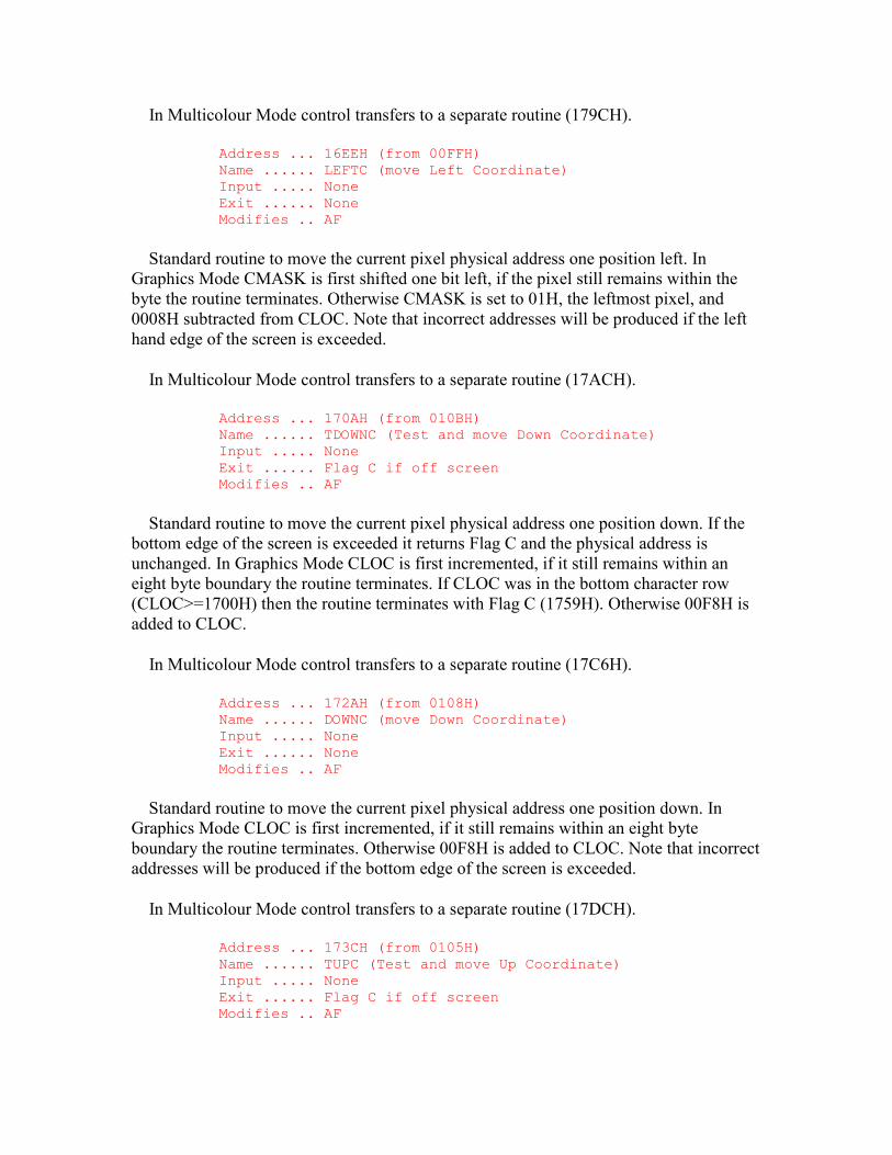
In Multicolour Mode control transfers to a separate routine (179CH).
Address ... 16EEH (from 00FFH) Name ...... LEFTC (move Left Coordinate) Input ..... None Exit ...... None Modifies .. AF
Standard routine to move the current pixel physical address one position left. In Graphics Mode CMASK is first shifted one bit left, if the pixel still remains within the byte the routine terminates. Otherwise CMASK is set to 01H, the leftmost pixel, and 0008H subtracted from CLOC. Note that incorrect addresses will be produced if the left hand edge of the screen is exceeded.
In Multicolour Mode control transfers to a separate routine (17ACH).
Address ... 170AH (from 010BH) Name ...... TDOWNC (Test and move Down Coordinate) Input ..... None Exit ...... Flag C if off screen Modifies .. AF
Standard routine to move the current pixel physical address one position down. If the bottom edge of the screen is exceeded it returns Flag C and the physical address is unchanged. In Graphics Mode CLOC is first incremented, if it still remains within an eight byte boundary the routine terminates. If CLOC was in the bottom character row (CLOC>=1700H) then the routine terminates with Flag C (1759H). Otherwise 00F8H is added to CLOC.
In Multicolour Mode control transfers to a separate routine (17C6H).
Address ... 172AH (from 0108H) Name ...... DOWNC (move Down Coordinate) Input ..... None Exit ...... None Modifies .. AF
Standard routine to move the current pixel physical address one position down. In Graphics Mode CLOC is first incremented, if it still remains within an eight byte boundary the routine terminates. Otherwise 00F8H is added to CLOC. Note that incorrect addresses will be produced if the bottom edge of the screen is exceeded.
In Multicolour Mode control transfers to a separate routine (17DCH).
Address ... 173CH (from 0105H) Name ...... TUPC (Test and move Up Coordinate) Input ..... None Exit ...... Flag C if off screen Modifies .. AF
Standard routine to move the current pixel physical address one position up. If the top edge of the screen is exceeded it returns with Flag C and the physical address is unchanged. In Graphics Mode CLOC is first decremented, if it still remains within an eight byte boundary the routine terminates. If CLOC was in the top character row (CLOC<0100H) then the routine terminates with Flag C. Otherwise 00F8H is subtracted from CLOC.
In Multicolour Mode control transfers to a separate routine (17E3H).
Address ... 175DH (from 0102H) Name ...... UPC (move Up Coordinate) Input ..... None Exit ...... None Modifies .. AF
Standard routine to move the current pixel physical address one position up. In Graphics Mode CLOC is first decremented, if it still remains within an eight byte boundary the routine terminates. Otherwise 00F8H is subtracted from CLOC. Note that incorrect addresses will be produced if the top edge of the screen is exceeded.
In Multicolour Mode control transfers to a separate routine (17F8H). - 74 - 4. ROM BIOS Address ... 1779H
Address @ (MSX only)
This is the Multicolour Mode version of the routine at 16ACH. It is identical to the Graphics Mode version except that CMASK is shifted four bit positions right and becomes F0H if a cell boundary is crossed. Address ... 178BH
Address @ (MSX only)
This is the Multicolour Mode version of the RIGHTC standard routine. It is identical to the Graphics Mode version except that CMASK is shifted four bit positions right and becomes F0H if a cell boundary is crossed. Address ... 179CH
Address @ (MSX only)
This is the Multicolour Mode version of the routine at 16D8H. It is identical to the Graphics Mode version except that CMASK is shifted four bit positions left and becomes 0FH if a cell boundary is crossed. Address ... 17ACH
Address @ (MSX only)
This is the Multicolour Mode version of the LEFTC standard routine. It is identical to the Graphics Mode version except that CMASK is shifted four bit positions left and becomes 0FH if a cell boundary is crossed. Address ... 17C6H
Address @ (MSX only)
This is the Multicolour Mode version of the TDOWNC standard routine. It is identical to the Graphics Mode version except that the bottom boundary address is 0500H instead of 1700H. There is a bug in this routine which will cause it to behave unpredictably if MLTCGP, the Character Pattern Table base address, is changed from its normal value of zero. There should be an EX DE,HL instruction inserted at address 17CEH.
If the Character Pattern Table base is increased the routine will think it has reached the bottom of the screen when it actually has not. This routine is used by the "PAINT" statement so the following demonstrates the fault:
10 BASE(17)=&H1000 20 SCREEN 3 30 PSET(200,0) 40 DRAW"D180L100U180R100" 50 PAINT(150,90) 60 GOTO 60
Address ... 17DCH Address @ (MSX only)
This is the Multicolour Mode version of the DOWNC standard routine, it is identical to the Graphics Mode version. - 75 - 4. ROM BIOS Address ... 17E3H
Address @ (MSX only)
This is the Multicolour Mode version of the TUPC standard routine. It is identical to the Graphics Mode version except that is has a bug as above, this time there should be an EX DE,HL instruction at address 17EBH.
If the Character Pattern Table base address is increased the routine will think it is within the table when it has actually exceeded the top edge of the screen. This may be demonstrated by removing the "R100" part of Line 40 in the previous program. Address ... 17F8H
Address @ (MSX only)
This is the Multicolour Mode version of the UPC standard routine, it is identical to the Graphics Mode version.
Address ... 1809H (from 0123H) Name ...... NSETCX (N [multiple] Set pixel Colour X [right])
Input ..... HL=Pixel fill count Exit ...... None Modifies .. AF, BC, DE, HL, EI
Standard routine to set the colour of multiple pixels horizontally rightwards from the current pixel physical address. Although its function can be duplicated by the SETC and RIGHTC standard routines this would result in significantly slower operation. The supplied pixel count should be chosen so that the right-hand edge of the screen is not passed as this will produce anomalous behaviour. The current pixel physical address is unchanged by this routine.
In Graphics Mode CMASK is first examined to determine the number of pixels to the right within the current character cell. Assuming the fill count is large enough these are then set (186CH). The remaining fill count is divided by eight to determine the number of whole character cells. Successive bytes in the Character Pattern Table are then zeroed and the corresponding bytes in the Colour Table set from ATRBYT to fill these whole cells. The remaining fill count is then converted to a bit mask, using the seven byte table at 185DH, and these pixels are set (186CH).
In Multicolour Mode control transfers to a separate routine (18BBH). Address ... 186CH
Address @ (MSX only)
This routine sets up to eight pixels within a cell to a specified colour in Graphics Mode. ATRBYT contains the colour code, register pair HL the address of the relevant byte in the Character Pattern Table and register A a bit mask, 11100000 for example, where every 1 specifies a bit to be set. - 76 - 4. ROM BIOS
If ATRBYT matches the existing 1 pixel colour in the corresponding Colour Table byte then each specified bit is set to 1 in the Character Pattern Table byte. If ATRBYT matches the existing 0 pixel colour in the corresponding Colour Table byte then each specified bit is set to 0 in the Character Pattern Table byte.
If ATRBYT does not match either of the existing colours in the Colour Table Byte then normally each specified bit is set to 1 in the Character Pattern Table byte and the 1 pixel colour changed in the Colour Table byte. However if this would result in all bits being set to 1 in the Character Pattern Table byte then each specified bit is set to 0 and the 0 pixel colour changed in the Colour Table byte. Address ... 18BBH
Address @ (MSX only)
This is the Multicolour Mode version of the NSETCX standard routine. The SETC and RIGHTC standard routines are called until the fill count is exhausted. Speed of operation is not so important in Multicolour Mode because of the lower screen resolution and the consequent reduction in the number of operations required.

Address ... 18C7H (from 0126H) Name ...... GTASPC (Get circle Aspect) Input ..... None Exit ...... DE=ASPCT1, HL=ASPCT2 Modifies .. DE, HL
Standard routine to return the "CIRCLE" statement default aspect ratios.
Address ... 18CFH (from 0129H) Name ...... PNTINI (Paint Initialization) Input ..... A=Boundary colour (0 to 15) Exit ...... Flag C if illegal colour Modifies .. AF
Standard routine to set the boundary colour for the "PAINT" statement. In Multicolour Mode the supplied colour code is placed in BDRATR. In Graphics Mode BDRATR is copied from ATRBYT as it is not possible to have separate paint and boundary colours.
Address ... 18E4H (from 012CH) Name ...... SCANR (Scan Right) Input ..... B=Fill switch, DE=Skip count Exit ...... DE=Skip remainder, HL=Pixel count Modifies .. AF, BC, DE, HL, EI
Standard routine used by the "PAINT" statement handler to search rightwards from the current pixel physical address until a colour code equal to BDRATR is found or the edge of the screen is reached. The terminating position becomes the current pixel physical address and the initial position is returned in CSAVEA and CSAVEM. The size of the traversed region is returned in register pair HL and FILNAM+1. The traversed region is normally filled in but this can be inhibited, in Graphics Mode only, by using an entry parameter of zero in register B. The skip count in register pair DE determines the maximum number of pixels of the required colour that may be ignored from the initial starting position. This facility is used by the "PAINT" statement handler to search for gaps in a horizontal boundary blocking its upward progress.
Address ... 197AH (from 012FH) Name ...... SCANL (Scan Left) Input ..... None Exit ...... HL=Pixel count Modifies .. AF, BC, DE, HL, EI
Standard routine to search leftwards from the current pixel physical address until a colour code equal to BDRATR is found or the edge of the screen is reached. The terminating position becomes the current pixel physical address and the size of the traversed region is returned in register pair HL. The traversed region is always filled in. Address ... 19C7H
Address @ (MSX only)
This routine is used by the SCANL and SCANR standard routines to check the current pixel's colour against the boundary colour in BDRATR.
Address ... 19DDH (from 00F0H) Name ...... TAPOOF (Tape Output Off) Input ..... None Exit ...... None Modifies .. EI
Standard routine to stop the cassette motor after data has been written to the cassette. After a delay of 550 ms, on MSX machines with one wait state, control drops into the TAPIOF standard routine.
Address ... 19E9H (from 00E7H) Name ...... TAPIOF (Tape Input Off) Input ..... None Exit ...... None Modifies .. EI
Standard routine to stop the cassette motor after data has been read from the cassette. The motor relay is opened via the PPI Mode Port. Note that interrupts, which must be disabled during cassette data transfers for timing reasons, are enabled as this routine terminates. - 78 - 4. ROM BIOS
Address ... 19F1H (from 00EAH) Name ...... TAPOON (Tape Output On) Input ..... A=Header length switch Exit ...... Flag C if CTRL-STOP termination Modifies .. AF, BC, HL, DI
Standard routine to turn the cassette motor on, wait 550 ms for the tape to come up to speed and then write a header to the cassette. A header is a burst of HI cycles written in front of every data block so the baud rate can be determined when the data is read back.
The length of the header is determined by the contents of register A: 00H=Short header, NZ=Long header. The BASIC cassette statements "SAVE", "CSAVE" and "BSAVE" all generate a long header at the start of the file, in front of the identification block, and thereafter use short headers between data blocks. The number of cycles in the header is also modified by the current baud rate so as to keep its duration constant:
1200 Baud SHORT ... 3840 Cycles ... 1.5 Seconds 1200 Baud LONG ... 15360 Cycles ... 6.1 Seconds 2400 Baud SHORT ... 7936 Cycles ... 1.6 Seconds 2400 Baud LONG ... 31744 Cycles ... 6.3 Seconds
After the motor has been turned on and the delay has expired the contents of HEADER are multiplied by two hundred and fifty- six and, if register A is non-zero, by a further factor of four to produce the cycle count. HI cycles are then generated (1A4DH) until the count is exhausted whereupon control transfers to the BREAKX standard routine.

Because the CTRL-STOP key is only examined at termination it is impossible to break out part way through this routine.
Address ... 1A19H (from 00EDH) Name ...... TAPOUT (Tape Output) Input ..... A=Data byte Exit ...... Flag C if CTRL-STOP termination Modifies .. AF, B, HL
Standard routine to write a single byte of data to the cassette. The MSX ROM uses a software driven FSK (Frequency Shift Keyed) method for storing information on the cassette. At the 1200 baud rate this is identical to the Kansas City Standard used by the BBC for the distribution of BASICODE programs.
At 1200 baud each 0 bit is written as one complete 1200 Hz LO cycle and each 1 bit as two complete 2400 Hz HI cycles. The data rate is thus constant as 0 and 1 bits have the same duration. When the 2400 baud rate is selected the two frequencies change to 2400 Hz and 4800 Hz but the format is otherwise unchanged. - 79 - 4. ROM BIOS
A byte of data is written with a 0 start bit (1A50H), eight data bits with the least significant bit first, and two 1 stop bits (1A40H). At the 1200 baud rate a single byte will
have a nominal duration of 11 x 833 誑 = 9.2 ms. After the stop bits have been written control transfers to the BREAKX standard routine to check the CTRL-STOP key. The byte 43H is shown below as it would be written to cassette:
+-+++++++++ +-+ +-+ +-+ +-+++++ +-+++++++++ | ||||||||| | | | | | | | ||||| | ||||||||| --+ +++++++++-+ +-+ +-+ +-+ +++++-+ +++++++++ | | | | | | | | | | | | START 0 1 2 3 4 5 6 7 STOP STOP 1 = two "short" transitions (as STOP BITS) 0 = one "long" transition (as START BIT)
Figure 39: Cassette Data Byte.
It is important not to leave too long an interval between bytes when writing data as this
will increase the error rate. An inter-byte gap of 80 誑, for example, produces a read failure rate of approximately twelve percent. If a substantial amount of processing is required between each byte then buffering should be used to lump data into headered blocks. The BASIC "SAVE" format is of this type. Address ... 1A39H
Address @ (MSX only)
This routine writes a single LO cycle with a length of approximately 816 誑 to the cassette. The length of each half of the cycle is taken from LOW and control transfers to the general cycle generator (1A50H). Address ... 1A40H
Address @ (MSX only)
This routine writes two HI cycles to the cassette. The first cycle is generated (1A4DH) followed by a 17 誑 delay and then the second cycle (1A4DH). Address ... 1A4DH
Address @ (MSX only)
This routine writes a single HI cycle with a length of approximately 396 誑 to the cassette. The length of each half of the cycle is taken from HIGH and control drops into the general cycle generator. Address ... 1A50H
Address @ (MSX only)
This routine writes a single cycle to the cassette. The length of the cycle's first half is supplied in register L and its second half in register H. The first length is counted down and then the Cas Out bit set via the PPI Mode Port. The second length is counted down and the Cas Out bit reset. - 80 - 4. ROM BIOS
On all MSX machines the Z80 runs at a clock frequency of 3.579545 MHz (280 ns) with one wait state during the M1 cycle. As this routine counts every 16T states each unit
increment in the length count represents a period of 4.47 誑. There is also a fixed
overhead of 20.7 誑 associated with the routine whatever the length count.
Address ... 1A63H (from 00EDH) Name ...... TAPION (Tape Input On) Input ..... None Exit ...... Flag C if CTRL-STOP termination Modifies .. AF, BC, DE, HL, DI
Standard routine to turn the cassette motor on, read the cassette until a header is found and then determine the baud rate. Successive cycles are read from the cassette and the length of each one measured (1B34H). When 1,111 cycles have been found with less than 35 誑 variation in their lengths a header has been located.
The next 256 cycles are then read (1B34H) and averaged to determine the cassette HI cycle length. This figure is multiplied by 1.5 and placed in LOWLIM where it defines the minimum acceptable length of a 0 start bit. The HI cycle length is placed in WINWID and will be used to discriminate between LO and HI cycles.
Address ... 1ABCH (from 00EDH) Name ...... TAPIN (Tape Input) Input ..... None Exit ...... A=Byte read, Flag C if CTRL-STOP or I/O error Modifies .. AF, BC, DE, L
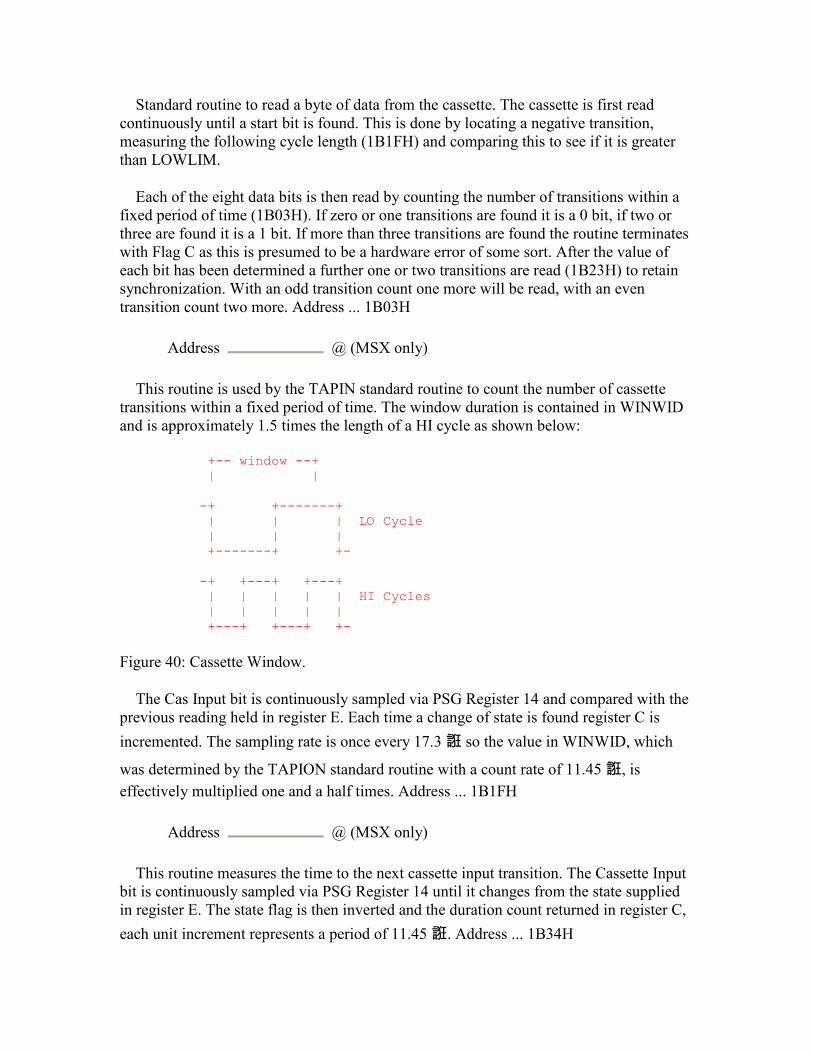
Standard routine to read a byte of data from the cassette. The cassette is first read continuously until a start bit is found. This is done by locating a negative transition, measuring the following cycle length (1B1FH) and comparing this to see if it is greater than LOWLIM.
Each of the eight data bits is then read by counting the number of transitions within a fixed period of time (1B03H). If zero or one transitions are found it is a 0 bit, if two or three are found it is a 1 bit. If more than three transitions are found the routine terminates with Flag C as this is presumed to be a hardware error of some sort. After the value of each bit has been determined a further one or two transitions are read (1B23H) to retain synchronization. With an odd transition count one more will be read, with an even transition count two more. Address ... 1B03H
Address @ (MSX only)
This routine is used by the TAPIN standard routine to count the number of cassette transitions within a fixed period of time. The window duration is contained in WINWID and is approximately 1.5 times the length of a HI cycle as shown below:
+-- window --+ | | -+ +-------+ | | | LO Cycle | | | +-------+ +- -+ +---+ +---+ | | | | | HI Cycles | | | | | +---+ +---+ +-
Figure 40: Cassette Window.
The Cas Input bit is continuously sampled via PSG Register 14 and compared with the previous reading held in register E. Each time a change of state is found register C is
incremented. The sampling rate is once every 17.3 誑 so the value in WINWID, which
was determined by the TAPION standard routine with a count rate of 11.45 誑, is effectively multiplied one and a half times. Address ... 1B1FH
Address @ (MSX only)
This routine measures the time to the next cassette input transition. The Cassette Input bit is continuously sampled via PSG Register 14 until it changes from the state supplied in register E. The state flag is then inverted and the duration count returned in register C, each unit increment represents a period of 11.45 誑. Address ... 1B34H
Address @ (MSX only)
This routine measures the length of a complete cassette cycle from negative transition to negative transition. The Cassette Input bit is sampled via PSG Register 14 until it goes to zero. The transition flag in register E is set to zero and the time to the positive transition measured (1B23H). The time to the negative transition is then measured (1B25H) and the total returned in register C.
Address ... 1B45H (from 0018H) Name ...... OUTDO (Output to Default Output device) Input ..... A=Character to output Exit ...... None Modifies .. EI
Standard routine used by the BASIC Interpreter to output a character to the current device. The ISFLIO standard routine is first used to check whether output is currently directed to an I/O buffer, if so control transfers to the sequential output driver (6C48H) via the CALBAS standard routine. If PRTFLG is zero control transfers to the CHPUT standard routine to output the character to the screen. Assuming the printer is active RAWPRT is checked. If this is non-zero the character is passed directly to the printer (1BABH), otherwise control drops into the OUTDLP standard routine.
Address ... 1B63H (014DH) Name ...... OUTDLP (Output to Default Line Printer) Input ..... A=Character to output Exit ...... None Modifies .. EI
Standard routine to output a character to the printer. If the character is a TAB code (09H) spaces are issued to the OUTDLP standard routine until LPTPOS is a multiple of eight (0, 8, 16 etc.) If the character is a CR code (0DH) LPTPOS is zeroed if it is any other control code LPTPOS is unaffected, if it is a displayable character LPTPOS is incremented.
If NTMSXP is zero, meaning an MSX-specific printer is connected, the character is passed directly to the printer (1BABH). Assuming a normal printer is connected the CNVCHR standard routine is used to check for graphic characters. If the character is a header code (01H) the routine terminates with no action. If it is a converted graphic character it is replaced by a space, all other characters are passed to the printer (1BACH). Address ... 1B97H
Address @ (MSX only)
This twenty byte table is used by the keyboard decoder to find the correct routine for a given key number:
KEY NUMBER TO FUNCTION ---------------------------------------
00H to 2FH 0F83H Rows 0 to 5 30H to 32H 0F10H SHIFT, CTRL, GRAPH 33H 0F36H CAP 34H 0F10H CODE 35H to 39H 0FC3H F1 to F5 3AH to 3BH 0F10H ESC, TAB 3CH 0F46H STOP 3DH to 40H 0F10H BS, CR, SEL, SPACE 41H 0F06H HOME 42H to 57H 0F10H INS, DEL, CURSOR
Address ... 1BABH Address @ (MSX only)
This routine is used by the OUTDLP standard routine to pass a character to the printer. It is sent via the LPTOUT standard routine, if this returns Flag C control transfers to the "Device I/O error" generator (73B2H) via the CALBAS standard routine. Address ... 1BBFH
Address @ (MSX only)
The following 2 KB contains the power-up character set. The first eight bytes contain the pattern for character code 00H, the second eight bytes the pattern for character code 01H and so on to character code FFH.
Address ... 23BFH (from 00AEH) Name ...... PINLIN (Prompt Input Line) Input ..... None Exit ...... HL=Start of text, Flag C if CTRL-STOP termination Modifies .. AF, BC, DE, HL, EI
Standard routine used by the BASIC Interpreter Mainloop to collect a logical line of text from the console. Control transfers to the INLIN standard routine just after the point where the previous line has been cut (23E0H).
Address ... 23CCH (from 00B4H) Name ...... QINLIN (Question Mark Input Line) Input ..... None Exit ...... HL=Start of text, Flag C if CTRL-STOP termination Modifies .. AF, BC, DE, HL, EI
Standard routine used by the "INPUT" statement handler to collect a logical line of text from the console. The characters "? " are displayed via the OUTDO standard routine and control drops into the INLIN standard routine.
Address ... 23D5H (from 00B1H) Name ...... INLIN (Input Line) Input ..... None Exit ...... HL=Start of text, Flag C if CTRL-STOP termination Modifies .. AF, BC, DE, HL, EI
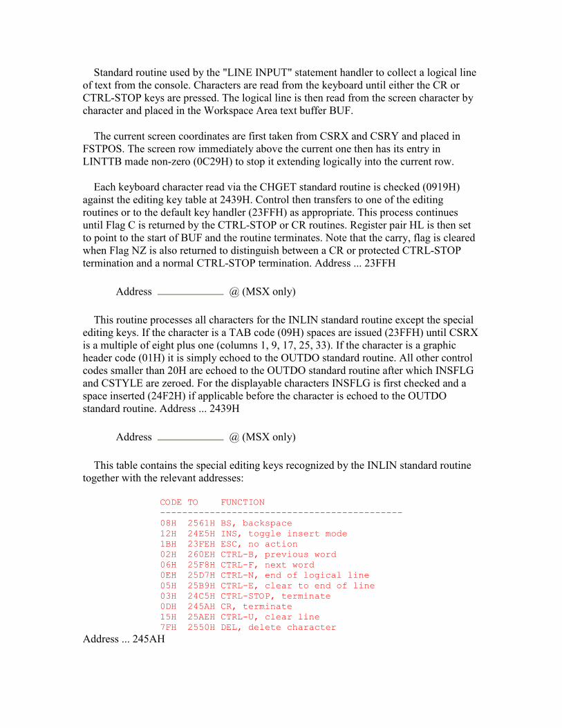
Standard routine used by the "LINE INPUT" statement handler to collect a logical line of text from the console. Characters are read from the keyboard until either the CR or CTRL-STOP keys are pressed. The logical line is then read from the screen character by character and placed in the Workspace Area text buffer BUF.
The current screen coordinates are first taken from CSRX and CSRY and placed in FSTPOS. The screen row immediately above the current one then has its entry in LINTTB made non-zero (0C29H) to stop it extending logically into the current row.
Each keyboard character read via the CHGET standard routine is checked (0919H) against the editing key table at 2439H. Control then transfers to one of the editing routines or to the default key handler (23FFH) as appropriate. This process continues until Flag C is returned by the CTRL-STOP or CR routines. Register pair HL is then set to point to the start of BUF and the routine terminates. Note that the carry, flag is cleared when Flag NZ is also returned to distinguish between a CR or protected CTRL-STOP termination and a normal CTRL-STOP termination. Address ... 23FFH
Address @ (MSX only)
This routine processes all characters for the INLIN standard routine except the special editing keys. If the character is a TAB code (09H) spaces are issued (23FFH) until CSRX is a multiple of eight plus one (columns 1, 9, 17, 25, 33). If the character is a graphic header code (01H) it is simply echoed to the OUTDO standard routine. All other control codes smaller than 20H are echoed to the OUTDO standard routine after which INSFLG and CSTYLE are zeroed. For the displayable characters INSFLG is first checked and a space inserted (24F2H) if applicable before the character is echoed to the OUTDO standard routine. Address ... 2439H
Address @ (MSX only)
This table contains the special editing keys recognized by the INLIN standard routine together with the relevant addresses:
CODE TO FUNCTION -------------------------------------------- 08H 2561H BS, backspace 12H 24E5H INS, toggle insert mode 1BH 23FEH ESC, no action 02H 260EH CTRL-B, previous word 06H 25F8H CTRL-F, next word 0EH 25D7H CTRL-N, end of logical line 05H 25B9H CTRL-E, clear to end of line 03H 24C5H CTRL-STOP, terminate 0DH 245AH CR, terminate 15H 25AEH CTRL-U, clear line 7FH 2550H DEL, delete character
Address ... 245AH
Address @ (MSX only)
This routine performs the CR operation for the INLIN standard routine. The starting coordinates of the logical line are found (266CH) and the cursor removed from the screen (0A2EH). Up to 254 characters are then read from the VDP VRAM (0BD8H) and placed in BUF. Any null codes (00H) are ignored, any characters smaller than 20H are replaced by a graphic header code (01H) and the character itself with 40H added. As the end of each physical row is reached LINTTB is checked (0C1DH) to see whether the logical line extends to the next physical row. Trailing spaces are then stripped from BUF and a zero byte added as an end of text marker. The cursor is restored to the screen (09E1H) and its coordinates set to the last physical row of the logical line via the POSIT standard routine. A LF code is issued to the OUTDO standard routine, INSFLG is zeroed and the routine terminates with a CR code (0DH) in register A and Flag NZ and C. This CR code will be echoed to the screen by the INLIN standard routine mainloop just before it terminates. Address ... 24C5H
Address @ (MSX only)
This routine performs the CTRL-STOP operation for the INLIN standard routine. The last physical row of the logical line is found by examining LINTTB (0C1DH), CSTYLE is zeroed, a zero byte is placed at the start of BUF and all music variables are cleared via the GICINI standard routine. TRPTBL is then examined (0454H) to see if an "ON STOP" statement is active, if so the cursor is reset (24AFH) and the routine terminates with Flag NZ,C. BASROM is then checked to see whether a protected ROM is running, if so the cursor is reset (24AFH) and the routine terminates with Flag NZ,C. Otherwise the cursor is reset (24B2H) and the routine terminates with Flag Z and C. Address ... 24E5H
Address @ (MSX only)
This routine performs the INS operation for the INLIN standard routine. The current state of INSFLG is inverted and control terminates via the CSTYLE setting routine (242CH). Address ... 24F2H
Address @ (MSX only)
This routine inserts a space character for the default key section of the INLIN standard routine. The cursor is removed (0A2EH) and the current cursor coordinates taken from CSRX and CSRY. The character at this position is read from the VDP VRAM (0BD8H) and replaced with a space (0BE6H). Successive characters are then copied one column position to the right until the end of the physical row is reached.
At this point LINTTB is examined (0C1DH) to determine whether the logical line is extended, if so the process continues on the next physical row. Otherwise the character taken from the last column position is examined, if this is a space the routine terminates
by replacing the cursor (09E1H). Otherwise the physical row's entry in LINTTB is zeroed to indicate an extended logical line. The number of the next physical row is compared with the number of rows on the screen (0C32H). If the next row is the last one the screen is scrolled up (0A88H), otherwise a blank row is inserted (0AB7H) and the copying process continues. Address ... 2550H
Address @ (MSX only)
This routine performs the DEL operation for the INLIN standard routine. If the current cursor position is at the rightmost column and the logical line is not extended no action is taken other than to write a space to the VDP VRAM (2595H). Otherwise a RIGHT code (1CH) is issued to the OUTDO standard routine and control drops into the BS routine. Address ... 2561H
Address @ (MSX only)
This routine performs the BS operation for the INLIN standard routine. The cursor is first removed (0A2EH) and the cursor column coordinate decremented unless it is at the leftmost position and the previous row is not extended. Characters are then read from the VDP VRAM (0BD8H) and written back one position to the left (0BE6H) until the end of the logical line is reached. At this point a space is written to the VDP VRAM (0BE6H) and the cursor character is restored (09E1H). Address ... 25AEH
Address @ (MSX only)
This routine performs the CTRL-U operation for the INLIN standard routine. The cursor is removed (0A2EH) and the start of the logical line located (266CH) and placed in CSRX and CSRY. The entire logical line is then cleared (25BEH). Address ... 25B9H
Address @ (MSX only)
This routine performs the CTRL-E operation for the INLIN standard routine. The cursor is removed (0A2EH) and the remainder of the physical row cleared (0AEEH). This process is repeated for successive physical rows until the end of the logical line is found in LINTBB (0C1DH). The cursor is then restored (09E1H), INSFLG zeroed and CSTLYE reset to a block cursor (242DH). Address ... 25D7H
Address @ (MSX only)
This routine performs the CTRL-N operation for the INLIN standard routine. The cursor is removed (0A2EH) and the last physical row of the logical line found by examination of LINTTB (0C1DH). Starting at the rightmost column of this physical row characters are read from the VDP VRAM (0BD8H) until a non-space character is found.
The cursor coordinates are then set one column to the right of this position (0A5BH) and the routine terminates by restoring the cursor (25CDH). Address ... 25F8H
Address @ (MSX only)
This routine performs the CTRL-F operation for the INLIN standard routine. The cursor is removed (0A2EH) and moved successively right (2624H) until a non-alphanumeric character is found. The cursor is then moved successively right (2624H) until an alphanumeric character is found. The routine terminates by restoring the cursor (25CDH). - 87 - 4. ROM BIOS Address ... 260EH
Address @ (MSX only)
This routine performs the CTRL-B operation for the INLIN standard routine. The cursor is removed (0A2EH) and moved successively left (2634H) until an alphanumeric character is found. The cursor is then moved successively left (2634H) until a non-alphanumeric character is found and then moved one position right (0A5BH). The routine terminates by restoring the cursor (25CDH). Address ... 2624H
Address @ (MSX only)
This routine moves the cursor one position right (0A5BH), loads register D with the rightmost column number, register E with the bottom row number and then tests for an alphanumeric character at the cursor position (263DH). Address ... 2634H
Address @ (MSX only)
This routine moves the cursor one position left (0A4CH), loads register D with the leftmost column number and register E with the top row number. The current cursor coordinates are compared with these values and the routine terminates Flag Z if the cursor is at this position. Otherwise the character at this position is read from the VDP VRAM (0BD8H) and checked to see if it is alphanumeric. If so the routine terminates Flag NZ and C otherwise it terminates Flag NZ and NC.
The alphanumeric characters are the digits "0" to "9" and the letters "A" to "Z" and "a" to "z". Also included are the graphics characters 86H to 9FH and A6H to FFH, these were originally Japanese letters and should have been excluded during the conversion to the UK ROM. Address ... 266CH
Address @ (MSX only)
This routine finds the start of a logical line and returns its screen coordinates in register pair HL. Each physical row above the current one is checked via the LINTTB table (0C1DH) until a non-extended row is found. The row immediately below this on the
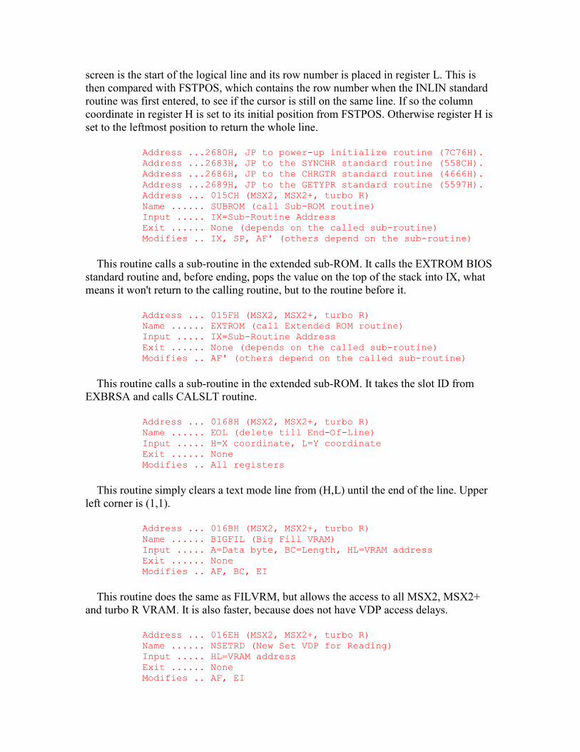
screen is the start of the logical line and its row number is placed in register L. This is then compared with FSTPOS, which contains the row number when the INLIN standard routine was first entered, to see if the cursor is still on the same line. If so the column coordinate in register H is set to its initial position from FSTPOS. Otherwise register H is set to the leftmost position to return the whole line.
Address ...2680H, JP to power-up initialize routine (7C76H). Address ...2683H, JP to the SYNCHR standard routine (558CH). Address ...2686H, JP to the CHRGTR standard routine (4666H). Address ...2689H, JP to the GETYPR standard routine (5597H). Address ... 015CH (MSX2, MSX2+, turbo R) Name ...... SUBROM (call Sub-ROM routine) Input ..... IX=Sub-Routine Address Exit ...... None (depends on the called sub-routine) Modifies .. IX, SP, AF' (others depend on the sub-routine)
This routine calls a sub-routine in the extended sub-ROM. It calls the EXTROM BIOS standard routine and, before ending, pops the value on the top of the stack into IX, what means it won't return to the calling routine, but to the routine before it.
Address ... 015FH (MSX2, MSX2+, turbo R) Name ...... EXTROM (call Extended ROM routine) Input ..... IX=Sub-Routine Address Exit ...... None (depends on the called sub-routine) Modifies .. AF' (others depend on the called sub-routine)
This routine calls a sub-routine in the extended sub-ROM. It takes the slot ID from EXBRSA and calls CALSLT routine.
Address ... 0168H (MSX2, MSX2+, turbo R) Name ...... EOL (delete till End-Of-Line) Input ..... H=X coordinate, L=Y coordinate Exit ...... None Modifies .. All registers
This routine simply clears a text mode line from (H,L) until the end of the line. Upper left corner is (1,1).
Address ... 016BH (MSX2, MSX2+, turbo R) Name ...... BIGFIL (Big Fill VRAM) Input ..... A=Data byte, BC=Length, HL=VRAM address Exit ...... None Modifies .. AF, BC, EI
This routine does the same as FILVRM, but allows the access to all MSX2, MSX2+ and turbo R VRAM. It is also faster, because does not have VDP access delays.
Address ... 016EH (MSX2, MSX2+, turbo R) Name ...... NSETRD (New Set VDP for Reading) Input ..... HL=VRAM address Exit ...... None Modifies .. AF, EI
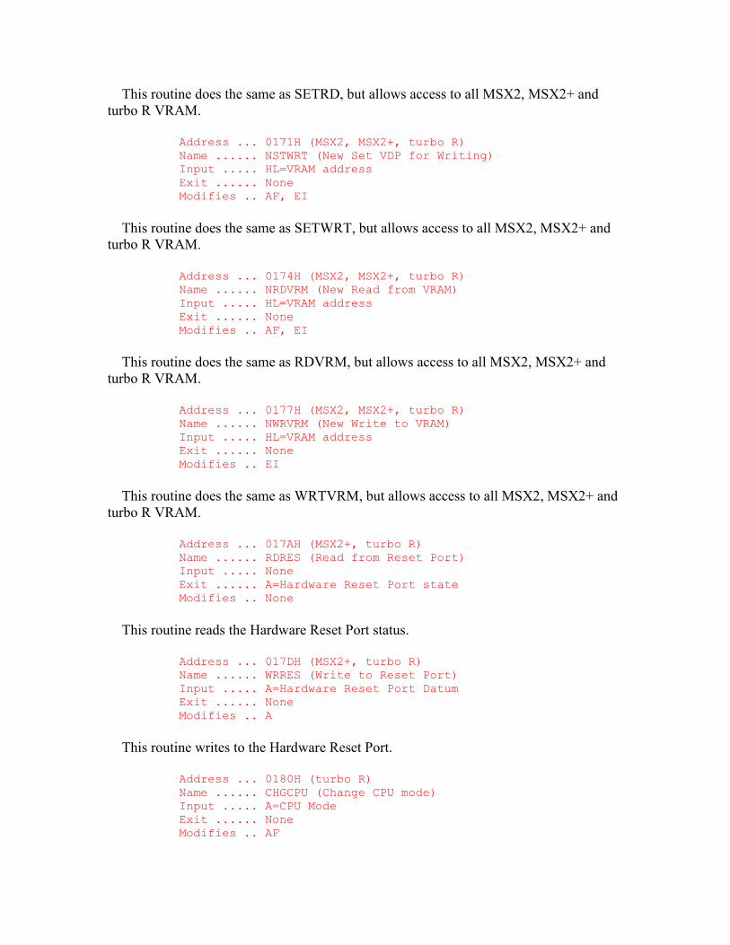
This routine does the same as SETRD, but allows access to all MSX2, MSX2+ and turbo R VRAM.
Address ... 0171H (MSX2, MSX2+, turbo R) Name ...... NSTWRT (New Set VDP for Writing) Input ..... HL=VRAM address Exit ...... None Modifies .. AF, EI
This routine does the same as SETWRT, but allows access to all MSX2, MSX2+ and turbo R VRAM.
Address ... 0174H (MSX2, MSX2+, turbo R) Name ...... NRDVRM (New Read from VRAM) Input ..... HL=VRAM address Exit ...... None Modifies .. AF, EI
This routine does the same as RDVRM, but allows access to all MSX2, MSX2+ and turbo R VRAM.
Address ... 0177H (MSX2, MSX2+, turbo R) Name ...... NWRVRM (New Write to VRAM) Input ..... HL=VRAM address Exit ...... None Modifies .. EI
This routine does the same as WRTVRM, but allows access to all MSX2, MSX2+ and turbo R VRAM.
Address ... 017AH (MSX2+, turbo R) Name ...... RDRES (Read from Reset Port) Input ..... None Exit ...... A=Hardware Reset Port state Modifies .. None
This routine reads the Hardware Reset Port status.
Address ... 017DH (MSX2+, turbo R) Name ...... WRRES (Write to Reset Port) Input ..... A=Hardware Reset Port Datum Exit ...... None Modifies .. A
This routine writes to the Hardware Reset Port.
Address ... 0180H (turbo R) Name ...... CHGCPU (Change CPU mode) Input ..... A=CPU Mode Exit ...... None Modifies .. AF
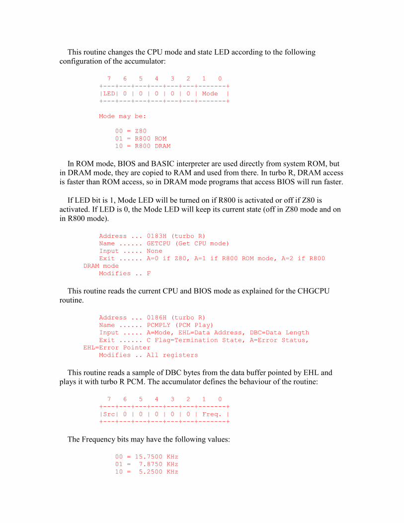
This routine changes the CPU mode and state LED according to the following configuration of the accumulator:
7 6 5 4 3 2 1 0 +---+---+---+---+---+---+-------+ |LED| 0 | 0 | 0 | 0 | 0 | Mode | +---+---+---+---+---+---+-------+ Mode may be: 00 = Z80 01 = R800 ROM 10 = R800 DRAM
In ROM mode, BIOS and BASIC interpreter are used directly from system ROM, but in DRAM mode, they are copied to RAM and used from there. In turbo R, DRAM access is faster than ROM access, so in DRAM mode programs that access BIOS will run faster.
If LED bit is 1, Mode LED will be turned on if R800 is activated or off if Z80 is activated. If LED is 0, the Mode LED will keep its current state (off in Z80 mode and on in R800 mode).
Address ... 0183H (turbo R) Name ...... GETCPU (Get CPU mode) Input ..... None Exit ...... A=0 if Z80, A=1 if R800 ROM mode, A=2 if R800 DRAM mode Modifies .. F
This routine reads the current CPU and BIOS mode as explained for the CHGCPU routine.
Address ... 0186H (turbo R) Name ...... PCMPLY (PCM Play) Input ..... A=Mode, EHL=Data Address, DBC=Data Length Exit ...... C Flag=Termination State, A=Error Status, EHL=Error Pointer Modifies .. All registers
This routine reads a sample of DBC bytes from the data buffer pointed by EHL and plays it with turbo R PCM. The accumulator defines the behaviour of the routine:
7 6 5 4 3 2 1 0 +---+---+---+---+---+---+-------+ |Src| 0 | 0 | 0 | 0 | 0 | Freq. | +---+---+---+---+---+---+-------+
The Frequency bits may have the following values:
00 = 15.7500 KHz 01 = 7.8750 KHz 10 = 5.2500 KHz
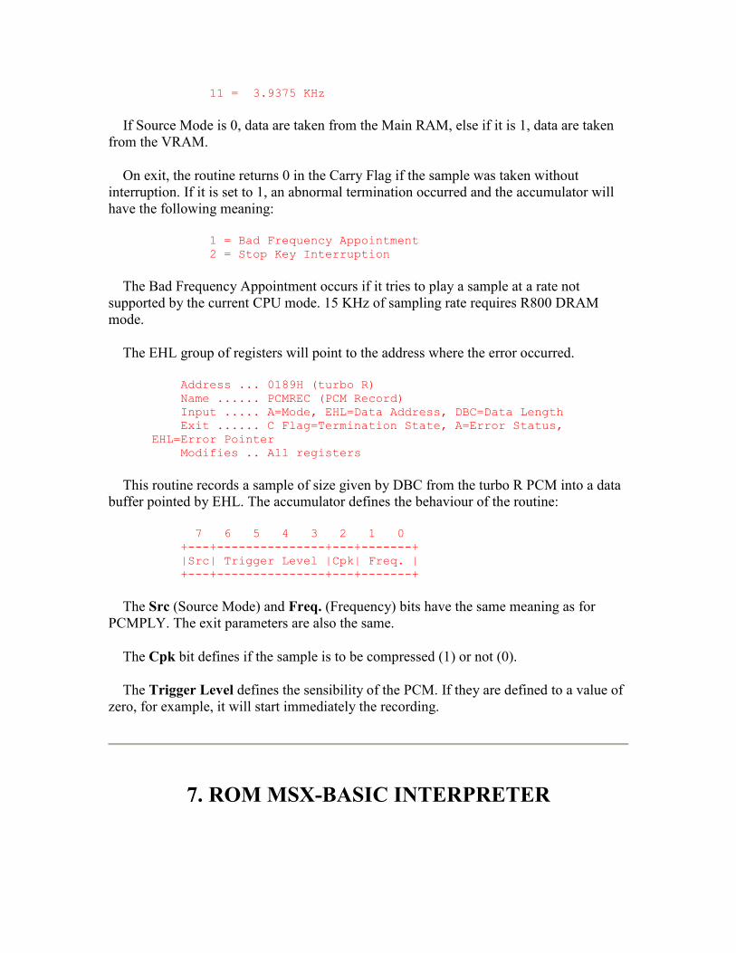
11 = 3.9375 KHz
If Source Mode is 0, data are taken from the Main RAM, else if it is 1, data are taken from the VRAM.
On exit, the routine returns 0 in the Carry Flag if the sample was taken without interruption. If it is set to 1, an abnormal termination occurred and the accumulator will have the following meaning:
1 = Bad Frequency Appointment 2 = Stop Key Interruption
The Bad Frequency Appointment occurs if it tries to play a sample at a rate not supported by the current CPU mode. 15 KHz of sampling rate requires R800 DRAM mode.
The EHL group of registers will point to the address where the error occurred.
Address ... 0189H (turbo R) Name ...... PCMREC (PCM Record) Input ..... A=Mode, EHL=Data Address, DBC=Data Length Exit ...... C Flag=Termination State, A=Error Status, EHL=Error Pointer Modifies .. All registers
This routine records a sample of size given by DBC from the turbo R PCM into a data buffer pointed by EHL. The accumulator defines the behaviour of the routine:
7 6 5 4 3 2 1 0 +---+---------------+---+-------+ |Src| Trigger Level |Cpk| Freq. | +---+---------------+---+-------+
The Src (Source Mode) and Freq. (Frequency) bits have the same meaning as for PCMPLY. The exit parameters are also the same.
The Cpk bit defines if the sample is to be compressed (1) or not (0).
The Trigger Level defines the sensibility of the PCM. If they are defined to a value of zero, for example, it will start immediately the recording.
7. ROM MSX-BASIC INTERPRETER
Microsoft BASIC has evolved over the years to its present position as the industry standard. It was originally written for the 8080 Microprocessor and even the MSX version is held in 8080 Assembly Language form. This process of continuous development means that there are less Z80-specific instructions than would be expected in a more modern program. It also means that numerous changes have been made and the result is a rather convoluted program. The structure of the Interpreter makes it unlikely that an application program will be able to use its many facilities. However most programs will need to cooperate with it to some extent so this chapter gives a detailed description of its operation.
There are four readily identifiable areas of importance within the Interpreter, the one most familiar to any user is the Mainloop (4134H). This collects numbered lines of text from the console and places them in order in the Program Text Area of memory until a direct statement is received.
The Runloop (NEWSTT, 4601H) is responsible for the execution of a program. It examines the first token of each program line and calls the appropriate routine to process the remainder of the statement. This continues until no more program text remains, control then returns to the Mainloop.
The analysis of numeric or string operands within a statement is performed by the Expression Evaluator (FRMEVL, 4C64H). Each expression is composed of factors, in turn analyzed by the Factor Evaluator (4DC7H), which are linked together by dyadic infix operators. As there are several types of operand, notably line numbers, which cannot form part of an expression in Microsoft BASIC the term "evaluated" is only used to refer to those that can. Otherwise a term such as "computed" will be used.
One point to note when examining the Interpreter in detail is that it contains a lot of trick code. The writers seem particularly fond of jumping into the middle of instructions to provide multiple entry points to a routine. As an example take the instruction:
3E D1 Normal: LD A,0D1H
When encountered in the usual way this will of course load the accumulator with the value D1H. However if it is entered at "Normal" then it will be executed as a POP DE instruction. The Interpreter has many similarly obscure sections.
The mathematical core of the MSX-BASIC is called "MSX Math-Pack" and is composed of several arithmetic, trigonometric and logarithmic functions, which work on all MSX machines and turbo R. Its usefulness for Assembly programming, though, is severely spoiled because these functions operate on BCD numeric representation, wasting numeric range (that is, precision) in favour of some easiness to the BASIC interpreter, which uses it. The following entries are part of the MSX Math-Pack, which can be used like a BIOS:
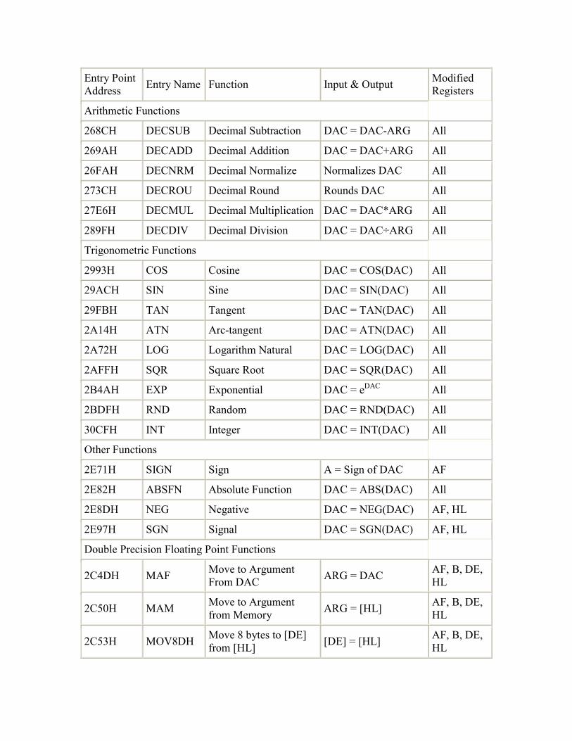
Entry Point Address Entry Name Function Input & Output Modified
Registers
Arithmetic Functions
268CH DECSUB Decimal Subtraction DAC = DAC-ARG All
269AH DECADD Decimal Addition DAC = DAC+ARG All
26FAH DECNRM Decimal Normalize Normalizes DAC All
273CH DECROU Decimal Round Rounds DAC All
27E6H DECMUL Decimal Multiplication DAC = DAC*ARG All
289FH DECDIV Decimal Division DAC = DAC÷ARG All
Trigonometric Functions
2993H COS Cosine DAC = COS(DAC) All
29ACH SIN Sine DAC = SIN(DAC) All
29FBH TAN Tangent DAC = TAN(DAC) All
2A14H ATN Arc-tangent DAC = ATN(DAC) All
2A72H LOG Logarithm Natural DAC = LOG(DAC) All
2AFFH SQR Square Root DAC = SQR(DAC) All
2B4AH EXP Exponential DAC = eDAC All
2BDFH RND Random DAC = RND(DAC) All
30CFH INT Integer DAC = INT(DAC) All
Other Functions
2E71H SIGN Sign A = Sign of DAC AF
2E82H ABSFN Absolute Function DAC = ABS(DAC) All
2E8DH NEG Negative DAC = NEG(DAC) AF, HL
2E97H SGN Signal DAC = SGN(DAC) AF, HL
Double Precision Floating Point Functions
2C4DH MAF Move to Argument From DAC ARG = DAC AF, B, DE,
HL
2C50H MAM Move to Argument from Memory ARG = [HL] AF, B, DE,
HL
2C53H MOV8DH Move 8 bytes to [DE] from [HL] [DE] = [HL] AF, B, DE,
HL
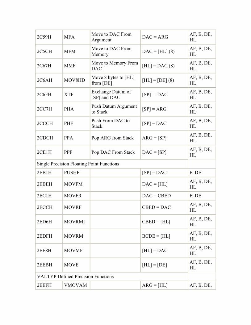
2C59H MFA Move to DAC From Argument DAC = ARG AF, B, DE,
HL
2C5CH MFM Move to DAC From Memory DAC = [HL] (8) AF, B, DE,
HL
2C67H MMF Move to Memory From DAC [HL] = DAC (8) AF, B, DE,
HL
2C6AH MOV8HD Move 8 bytes to [HL] from [DE] [HL] = [DE] (8) AF, B, DE,
HL
2C6FH XTF Exchange Datum of [SP] and DAC [SP] ⇒ DAC AF, B, DE,
HL
2CC7H PHA Push Datum Argument to Stack [SP] = ARG AF, B, DE,
HL
2CCCH PHF Push From DAC to Stack [SP] = DAC AF, B, DE,
HL
2CDCH PPA Pop ARG from Stack ARG = [SP] AF, B, DE, HL
2CE1H PPF Pop DAC From Stack DAC = [SP] AF, B, DE, HL
Single Precision Floating Point Functions
2EB1H PUSHF [SP] = DAC F, DE
2EBEH MOVFM DAC = [HL] AF, B, DE, HL
2EC1H MOVFR DAC = CBED F, DE
2ECCH MOVRF CBED = DAC AF, B, DE, HL
2ED6H MOVRMI CBED = [HL] AF, B, DE, HL
2EDFH MOVRM BCDE = [HL] AF, B, DE, HL
2EE8H MOVMF [HL] = DAC AF, B, DE, HL
2EEBH MOVE [HL] = [DE] AF, B, DE, HL
VALTYP Defined Precision Functions
2EEFH VMOVAM ARG = [HL] AF, B, DE,
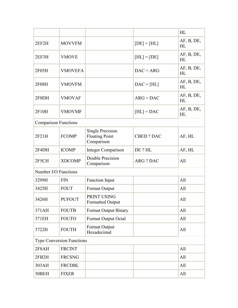
HL
2EF2H MOVVFM [DE] = [HL] AF, B, DE, HL
2EF3H VMOVE [HL] = [DE] AF, B, DE, HL
2F05H VMOVEFA DAC = ARG AF, B, DE, HL
2F08H VMOVFM DAC = [HL] AF, B, DE, HL
2F0DH VMOVAF ARG = DAC AF, B, DE, HL
2F10H VMOVMF [HL] = DAC AF, B, DE, HL
Comparison Functions
2F21H FCOMP Single Precision Floating Point Comparison
CBED ? DAC AF, HL
2F4DH ICOMP Integer Comparison DE ? HL AF, HL
2F5CH XDCOMP Double Precision Comparison ARG ? DAC All
Number I/O Functions
3299H FIN Function Input All
3425H FOUT Format Output All
3426H PUFOUT PRINT USING Formatted Output All
371AH FOUTB Format Output Binary All
371EH FOUTO Format Output Octal All
3722H FOUTH Format Output Hexadecimal All
Type Conversion Functions
2F8AH FRCINT All
2FB2H FRCSNG All
303AH FRCDBL All
30BEH FIXER All
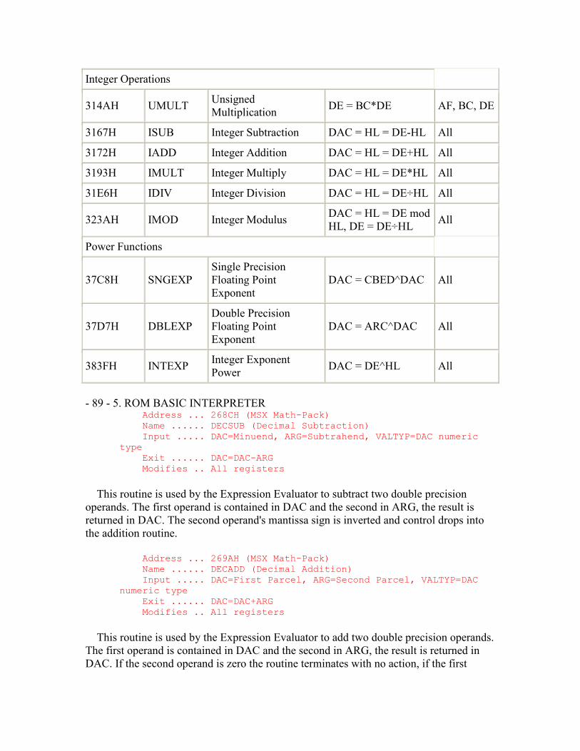
Integer Operations
314AH UMULT Unsigned Multiplication DE = BC*DE AF, BC, DE
3167H ISUB Integer Subtraction DAC = HL = DE-HL All
3172H IADD Integer Addition DAC = HL = DE+HL All
3193H IMULT Integer Multiply DAC = HL = DE*HL All
31E6H IDIV Integer Division DAC = HL = DE÷HL All
323AH IMOD Integer Modulus DAC = HL = DE mod HL, DE = DE÷HL All
Power Functions
37C8H SNGEXP Single Precision Floating Point Exponent
DAC = CBED^DAC All
37D7H DBLEXP Double Precision Floating Point Exponent
DAC = ARC^DAC All
383FH INTEXP Integer Exponent Power DAC = DE^HL All
- 89 - 5. ROM BASIC INTERPRETER
Address ... 268CH (MSX Math-Pack) Name ...... DECSUB (Decimal Subtraction) Input ..... DAC=Minuend, ARG=Subtrahend, VALTYP=DAC numeric type Exit ...... DAC=DAC-ARG Modifies .. All registers
This routine is used by the Expression Evaluator to subtract two double precision operands. The first operand is contained in DAC and the second in ARG, the result is returned in DAC. The second operand's mantissa sign is inverted and control drops into the addition routine.
Address ... 269AH (MSX Math-Pack) Name ...... DECADD (Decimal Addition) Input ..... DAC=First Parcel, ARG=Second Parcel, VALTYP=DAC numeric type Exit ...... DAC=DAC+ARG Modifies .. All registers
This routine is used by the Expression Evaluator to add two double precision operands. The first operand is contained in DAC and the second in ARG, the result is returned in DAC. If the second operand is zero the routine terminates with no action, if the first
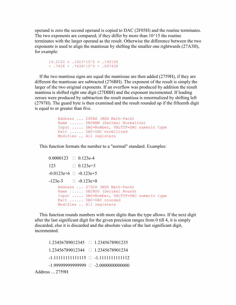
operand is zero the second operand is copied to DAC (2F05H) and the routine terminates. The two exponents are compared, if they differ by more than 10^15 the routine terminates with the larger operand as the result. Otherwise the difference between the two exponents is used to align the mantissae by shifting the smaller one rightwards (27A3H), for example:
19.2100 = .1921*10^2 = .192100 + .7436 = .7436*10^0 = .007436
If the two mantissa signs are equal the mantissae are then added (2759H), if they are different the mantissae are subtracted (276BH). The exponent of the result is simply the larger of the two original exponents. If an overflow was produced by addition the result mantissa is shifted right one digit (27DBH) and the exponent incremented. If leading zeroes were produced by subtraction the result mantissa is renormalized by shifting left (2797H). The guard byte is then examined and the result rounded up if the fifteenth digit is equal to or greater than five.
Address ... 26FAH (MSX Math-Pack) Name ...... DECNRM (Decimal Normalize) Input ..... DAC=Number, VALTYP=DAC numeric type Exit ...... DAC=DAC normilized Modifies .. All registers
This function formats the number to a "normal" standard. Examples:
0.0000123 ⇒ 0.123e-4
123 ⇒ 0.123e+3
-0.0123e+6 ⇒ -0.123e+5
-123e-3 ⇒ -0.123e+0 Address ... 273CH (MSX Math-Pack) Name ...... DECROU (Decimal Round) Input ..... DAC=Number, VALTYP=DAC numeric type Exit ...... DAC=DAC rounded Modifies .. All registers
This function rounds numbers with more digits than the type allows. If the next digit after the last significant digit for the given precision ranges from 0 till 4, it is simply discarded, else it is discarded and the absolute value of the last significant digit, incremented.
1.23456789012345 ⇒ 1.2345678901235
1.23456789012344 ⇒ 1.2345678901234
-1.11111111111115 ⇒ -1.1111111111112
-1.99999999999999 ⇒ -2.0000000000000 Address ... 2759H
Address @ (MSX only)
This routine adds the two double precision mantissae contained in DAC and ARG and returns the result in DAC. Addition commences at the least significant positions, DAC+7 and ARG+7, and proceeds two digits at a time for the seven bytes. Address ... 276BH
Address @ (MSX only)
This routine subtracts the two double precision mantissae contained in DAC and ARG and returns the result in DAC. Subtraction commences at the guard bytes, DAC+8 and ARG+8, and proceeds two digits at a time for the eight bytes. If the result underflows it is corrected by subtracting it from zero and inverting the mantissa sign, for example:
0.17-0.85 = 0.32 = -0.68
- 90 - 5. ROM BASIC INTERPRETER Address ... 2797H Address @ (MSX only)
This routine shifts the double precision mantissa contained in DAC one digit left. Address ... 27A3H
Address @ (MSX only)
This routine shifts a double precision mantissa right. The number of digits to shift is supplied in register A, the address of the mantissa's most significant byte is supplied in register pair HL. The digit count is first divided by two to separate the byte and digit counts. The required number of whole bytes are then shifted right and the most significant bytes zeroed. If an odd number of digits was specified the mantissa is then shifted a further one digit right.
Address ... 27E6H (MSX Math-Pack) Name ...... DECMUL (Decimal Multiplication) Input ..... DAC=Multiplicand, ARG=Multiplier, VALTYP=DAC numeric type Exit ...... DAC=DAC*ARG (Product) Modifies .. All registers
This routine is used by the Expression Evaluator to multiply two double precision operands. The first operand (multiplicand) is contained in DAC and the second (multiplier) in ARG, the result (product) is returned in DAC. If either operand is zero the routine terminates with a zero result (2E7DH). Otherwise the two exponents are added to produce the result exponent. If this is smaller than 10^-63 the routine terminates with a zero result, if it is greater than 10^63 an "Overflow error" is generated (4067H). The two mantissa signs are then processed to yield the sign of the result, if they are the same the result is positive, if they differ it is negative.
Even though the mantissae are in BCD format they are multiplied using the normal binary add and shift method. To accomplish this the first operand is successively multiplied by two (288AH) to produce the constants X*80, X*40, X*20, X*10, X*8, X*4, X*2, and X in the HOLD8 buffer. The second operand remains in ARG and DAC is zeroed to function as the product accumulator. Multiplication proceeds by taking successive pairs of digits from the second operand starting with the least significant pair. For each 1 bit in the digit pair the appropriate multiple of the first operand is added to the product. As an example the single multiplication 1823*96 would produce:
1823*10010110=(1823*80)+(1823*10)+(1823*4)+(1823*2)
As each digit pair is completed the product is shifted two digits right. When all seven digit pairs have been processed the routine terminates by renormalizing and rounding up the product (26FAH).
The time required for a multiplication depends largely upon the number of 1 bits in the second operand. The worst case, when all the digits are sevens, can take up to 11ms compared to the average of approximately 7ms. - 91 - 5. ROM BASIC INTERPRETER Address ... 288AH
Address @ (MSX only)
This routine doubles a double precision mantissa three successive times to produce the products X*2, X*4 and X*8. The address of the mantissa's least significant byte is supplied in register pair DE. The products are stored at successively lower addresses commencing immediately below the operand.
Address ... 289FH (MSX Math-Pack) Name ...... DECMUL (Decimal Division) Input ..... DAC=Dividend, ARG=Divisor, VALTYP=DAC numeric type Exit ...... DAC=DAC÷ARG Modifies .. All registers
This routine is used by the Expression Evaluator to divide two double precision operands. The first operand is contained in DAC and the second in ARG, the result is returned in DAC. If the first operand is zero the routine terminates with a zero result if the second operand is zero a "Division by zero" error is generated (4058H). Otherwise the two exponents are subtracted to produce the result exponent and the two mantissa signs processed to yield the sign of the result. If they are the same the result is positive, if they differ it is negative.
The mantissae are divided using the normal long division method. The second operand is repeatedly subtracted from the first until underflow to produce a single digit of the result. The second operand is then added back to restore the remainder (2761H), the digit is stored in HOLD and the first operand is shifted one digit left. When the first operand has been completely shifted out the result is copied from HOLD to DAC then
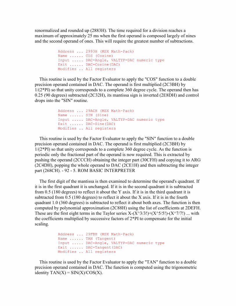
renormalized and rounded up (2883H). The time required for a division reaches a maximum of approximately 25 ms when the first operand is composed largely of nines and the second operand of ones. This will require the greatest number of subtractions.
Address ... 2993H (MSX Math-Pack) Name ...... COS (Cosine) Input ..... DAC=Angle, VALTYP=DAC numeric type Exit ...... DAC=Cosine(DAC) Modifies .. All registers
This routine is used by the Factor Evaluator to apply the "COS" function to a double precision operand contained in DAC. The operand is first multiplied (2C3BH) by 1/(2*PI) so that unity corresponds to a complete 360 degree cycle. The operand then has 0.25 (90 degrees) subtracted (2C32H), its mantissa sign is inverted (2E8DH) and control drops into the "SIN" routine.
Address ... 29ACH (MSX Math-Pack) Name ...... SIN (Sine) Input ..... DAC=Angle, VALTYP=DAC numeric type Exit ...... DAC=Sine(DAC) Modifies .. All registers
This routine is used by the Factor Evaluator to apply the "SIN" function to a double precision operand contained in DAC. The operand is first multiplied (2C3BH) by 1/(2*PI) so that unity corresponds to a complete 360 degree cycle. As the function is periodic only the fractional part of the operand is now required. This is extracted by pushing the operand (2CCCH) obtaining the integer part (30CFH) and copying it to ARG (2C4DH), popping the whole operand to DAC (2CE1H) and then subtracting the integer part (268CH). - 92 - 5. ROM BASIC INTERPRETER
The first digit of the mantissa is then examined to determine the operand's quadrant. If it is in the first quadrant it is unchanged. If it is in the second quadrant it is subtracted from 0.5 (180 degrees) to reflect it about the Y axis. If it is in the third quadrant it is subtracted from 0.5 (180 degrees) to reflect it about the X axis. If it is in the fourth quadrant 1.0 (360 degrees) is subtracted to reflect it about both axes. The function is then computed by polynomial approximation (2C88H) using the list of coefficients at 2DEFH. These are the first eight terms in the Taylor series X-(X^3/3!)+(X^5/5!)-(X^7/7!) ... with the coefficients multiplied by successive factors of 2*PI to compensate for the initial scaling.
Address ... 29FBH (MSX Math-Pack) Name ...... TAN (Tangent) Input ..... DAC=Angle, VALTYP=DAC numeric type Exit ...... DAC=Tangent(DAC) Modifies .. All registers
This routine is used by the Factor Evaluator to apply the "TAN" function to a double precision operand contained in DAC. The function is computed using the trigonometric identity TAN(X) = SIN(X)/COS(X).
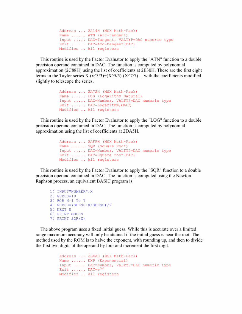
Address ... 2A14H (MSX Math-Pack) Name ...... ATN (Arc-tangent) Input ..... DAC=Tangent, VALTYP=DAC numeric type Exit ...... DAC=Arc-tangent(DAC) Modifies .. All registers
This routine is used by the Factor Evaluator to apply the "ATN" function to a double precision operand contained in DAC. The function is computed by polynomial approximation (2C88H) using the list of coefficients at 2E30H. These are the first eight terms in the Taylor series X-(x^3/3)+(X^5/5)-(X^7/7) ... with the coefficients modified slightly to telescope the series.
Address ... 2A72H (MSX Math-Pack) Name ...... LOG (Logarithm Natural) Input ..... DAC=Number, VALTYP=DAC numeric type Exit ...... DAC=Logarithme(DAC) Modifies .. All registers
This routine is used by the Factor Evaluator to apply the "LOG" function to a double precision operand contained in DAC. The function is computed by polynomial approximation using the list of coefficients at 2DA5H.
Address ... 2AFFH (MSX Math-Pack) Name ...... SQR (Square Root) Input ..... DAC=Number, VALTYP=DAC numeric type Exit ...... DAC=Square root(DAC) Modifies .. All registers
This routine is used by the Factor Evaluator to apply the "SQR" function to a double precision operand contained in DAC. The function is computed using the Newton-Raphson process, an equivalent BASIC program is:
10 INPUT"NUMBER";X 20 GUESS=10 30 FOR N=1 To 7 40 GUESS=(GUESS+X/GUESS)/2 50 NEXT N 60 PRINT GUESS 70 PRINT SQR(X)
The above program uses a fixed initial guess. While this is accurate over a limited range maximum accuracy will only be attained if the initial guess is near the root. The method used by the ROM is to halve the exponent, with rounding up, and then to divide the first two digits of the operand by four and increment the first digit.
Address ... 2B4AH (MSX Math-Pack) Name ...... EXP (Exponential) Input ..... DAC=Number, VALTYP=DAC numeric type Exit ...... DAC=eDAC Modifies .. All registers
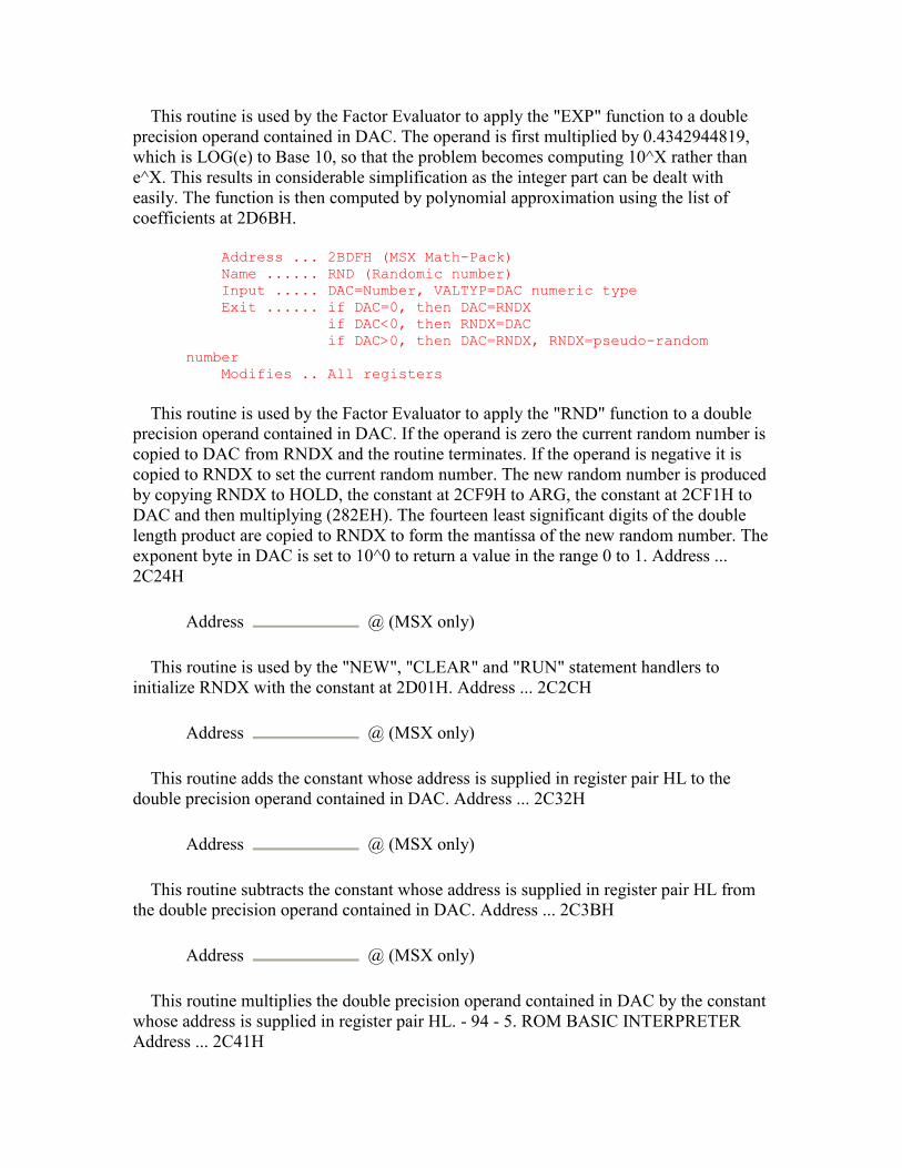
This routine is used by the Factor Evaluator to apply the "EXP" function to a double precision operand contained in DAC. The operand is first multiplied by 0.4342944819, which is LOG(e) to Base 10, so that the problem becomes computing 10^X rather than e^X. This results in considerable simplification as the integer part can be dealt with easily. The function is then computed by polynomial approximation using the list of coefficients at 2D6BH.
Address ... 2BDFH (MSX Math-Pack) Name ...... RND (Randomic number) Input ..... DAC=Number, VALTYP=DAC numeric type Exit ...... if DAC=0, then DAC=RNDX if DAC<0, then RNDX=DAC if DAC>0, then DAC=RNDX, RNDX=pseudo-random number Modifies .. All registers
This routine is used by the Factor Evaluator to apply the "RND" function to a double precision operand contained in DAC. If the operand is zero the current random number is copied to DAC from RNDX and the routine terminates. If the operand is negative it is copied to RNDX to set the current random number. The new random number is produced by copying RNDX to HOLD, the constant at 2CF9H to ARG, the constant at 2CF1H to DAC and then multiplying (282EH). The fourteen least significant digits of the double length product are copied to RNDX to form the mantissa of the new random number. The exponent byte in DAC is set to 10^0 to return a value in the range 0 to 1. Address ... 2C24H
Address @ (MSX only)
This routine is used by the "NEW", "CLEAR" and "RUN" statement handlers to initialize RNDX with the constant at 2D01H. Address ... 2C2CH
Address @ (MSX only)
This routine adds the constant whose address is supplied in register pair HL to the double precision operand contained in DAC. Address ... 2C32H
Address @ (MSX only)
This routine subtracts the constant whose address is supplied in register pair HL from the double precision operand contained in DAC. Address ... 2C3BH
Address @ (MSX only)
This routine multiplies the double precision operand contained in DAC by the constant whose address is supplied in register pair HL. - 94 - 5. ROM BASIC INTERPRETER Address ... 2C41H
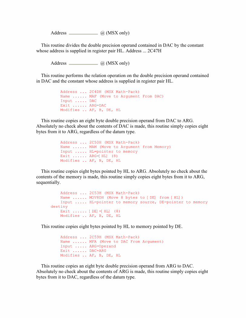
Address @ (MSX only)
This routine divides the double precision operand contained in DAC by the constant whose address is supplied in register pair HL. Address ... 2C47H
Address @ (MSX only)
This routine performs the relation operation on the double precision operand contained in DAC and the constant whose address is supplied in register pair HL.
Address ... 2C4DH (MSX Math-Pack) Name ...... MAF (Move to Argument From DAC) Input ..... DAC Exit ...... ARG=DAC Modifies .. AF, B, DE, HL
This routine copies an eight byte double precision operand from DAC to ARG. Absolutely no check about the contents of DAC is made, this routine simply copies eight bytes from it to ARG, regardless of the datum type.
Address ... 2C50H (MSX Math-Pack) Name ...... MAM (Move to Argument from Memory) Input ..... HL=pointer to memory Exit ...... ARG=[HL] (8) Modifies .. AF, B, DE, HL
This routine copies eight bytes pointed by HL to ARG. Absolutely no check about the contents of the memory is made, this routine simply copies eight bytes from it to ARG, sequentially.
Address ... 2C53H (MSX Math-Pack) Name ...... MOV8DH (Move 8 bytes to [DE] from [HL]) Input ..... HL=pointer to memory source, DE=pointer to memory destiny Exit ...... [DE]=[HL] (8) Modifies .. AF, B, DE, HL
This routine copies eight bytes pointed by HL to memory pointed by DE.
Address ... 2C59H (MSX Math-Pack) Name ...... MFA (Move to DAC From Argument) Input ..... ARG=Operand Exit ...... DAC=ARG Modifies .. AF, B, DE, HL
This routine copies an eight byte double precision operand from ARG to DAC. Absolutely no check about the contents of ARG is made, this routine simply copies eight bytes from it to DAC, regardless of the datum type.
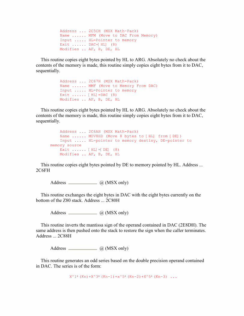
Address ... 2C5CH (MSX Math-Pack) Name ...... MFM (Move to DAC From Memory) Input ..... HL=Pointer to memory Exit ...... DAC=[HL] (8) Modifies .. AF, B, DE, HL
This routine copies eight bytes pointed by HL to ARG. Absolutely no check about the contents of the memory is made, this routine simply copies eight bytes from it to DAC, sequentially.
Address ... 2C67H (MSX Math-Pack) Name ...... MMF (Move to Memory From DAC) Input ..... HL=Pointer to memory Exit ...... [HL]=DAC (8) Modifies .. AF, B, DE, HL
This routine copies eight bytes pointed by HL to ARG. Absolutely no check about the contents of the memory is made, this routine simply copies eight bytes from it to DAC, sequentially.
Address ... 2C6AH (MSX Math-Pack) Name ...... MOV8HD (Move 8 bytes to [HL] from [DE]) Input ..... HL=pointer to memory destiny, DE=pointer to memory source Exit ...... [HL]=[DE] (8) Modifies .. AF, B, DE, HL
This routine copies eight bytes pointed by DE to memory pointed by HL. Address ... 2C6FH
Address @ (MSX only)
This routine exchanges the eight bytes in DAC with the eight bytes currently on the bottom of the Z80 stack. Address ... 2C80H
Address @ (MSX only)
This routine inverts the mantissa sign of the operand contained in DAC (2E8DH). The same address is then pushed onto the stack to restore the sign when the caller terminates. Address ... 2C88H
Address @ (MSX only)
This routine generates an odd series based on the double precision operand contained in DAC. The series is of the form:
X^1*(Kn)+X^3*(Kn-1)+x^5*(Kn-2)+X^5*(Kn-3) ...
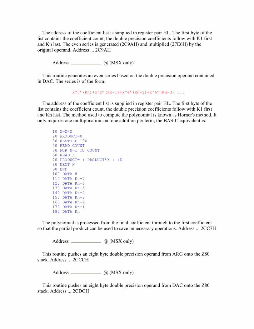
The address of the coefficient list is supplied in register pair HL. The first byte of the list contains the coefficient count, the double precision coefficients follow with K1 first and Kn last. The even series is generated (2C9AH) and multiplied (27E6H) by the original operand. Address ... 2C9AH
Address @ (MSX only)
This routine generates an even series based on the double precision operand contained in DAC. The series is of the form:
X^0*(Kn)+x^2*(Kn-1)+x^4*(Kn-2)+x^6*(Kn-3) ...
The address of the coefficient list is supplied in register pair HL. The first byte of the list contains the coefficient count, the double precision coefficients follow with K1 first and Kn last. The method used to compute the polynomial is known as Horner's method. It only requires one multiplication and one addition per term, the BASIC equivalent is:
10 X=X*X 20 PRODUCT=0 30 RESTORE 100 40 READ COUNT 50 FOR N=1 TO COUNT 60 READ K 70 PRODUCT= ( PRODUCT*X ) +K 80 NEXT N 90 END 100 DATA 8 110 DATA Kn-7 120 DATA Kn-6 130 DATA Kn-5 140 DATA Kn-4 150 DATA Kn-3 160 DATA Kn-2 170 DATA Kn-1 180 DATA Kn
The polynomial is processed from the final coefficient through to the first coefficient so that the partial product can be used to save unnecessary operations. Address ... 2CC7H
Address @ (MSX only)
This routine pushes an eight byte double precision operand from ARG onto the Z80 stack. Address ... 2CCCH
Address @ (MSX only)
This routine pushes an eight byte double precision operand from DAC onto the Z80 stack. Address ... 2CDCH
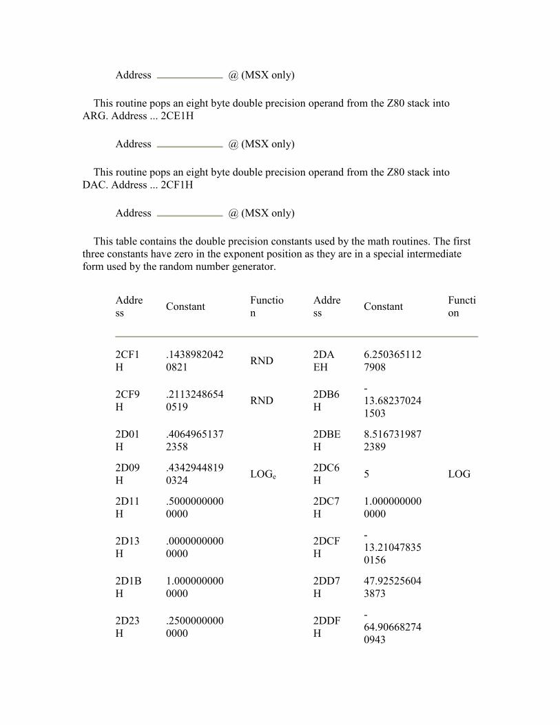
Address @ (MSX only)
This routine pops an eight byte double precision operand from the Z80 stack into ARG. Address ... 2CE1H
Address @ (MSX only)
This routine pops an eight byte double precision operand from the Z80 stack into DAC. Address ... 2CF1H
Address @ (MSX only)
This table contains the double precision constants used by the math routines. The first three constants have zero in the exponent position as they are in a special intermediate form used by the random number generator.
Address Constant Functio
n
Address Constant Functi
on
2CF1H
.14389820420821 RND 2DA
EH 6.2503651127908
2CF9H
.21132486540519 RND 2DB6
H
-13.682370241503
2D01H
.40649651372358 2DBE
H 8.5167319872389
2D09H
.43429448190324 LOGe
2DC6H 5 LOG
2D11H
.50000000000000 2DC7
H 1.0000000000000
2D13H
.00000000000000 2DCF
H
-13.210478350156
2D1BH
1.0000000000000 2DD7
H 47.925256043873
2D23H
.25000000000000
2DDFH
-64.906682740943
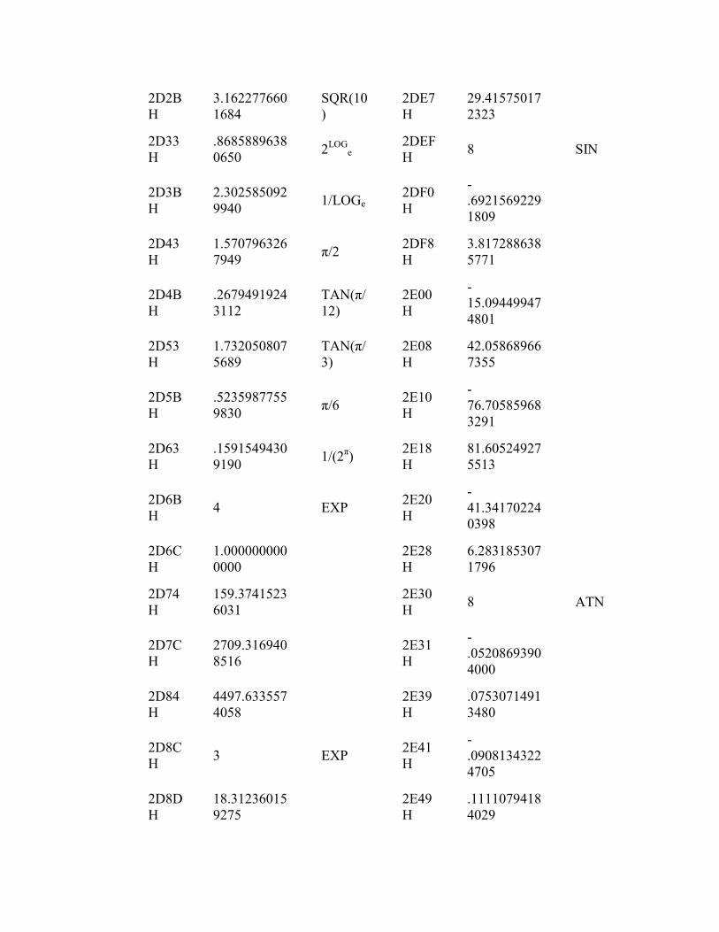
2D2BH
3.1622776601684
SQR(10)
2DE7H
29.415750172323
2D33H
.86858896380650 2LOG
e 2DEFH 8 SIN
2D3BH
2.3025850929940 1/LOGe
2DF0H
-.69215692291809
2D43H
1.5707963267949 π/2 2DF8
H 3.8172886385771
2D4BH
.26794919243112
TAN(π/12)
2E00H
-15.094499474801
2D53H
1.7320508075689
TAN(π/3)
2E08H
42.058689667355
2D5BH
.52359877559830 π/6 2E10
H
-76.705859683291
2D63H
.15915494309190 1/(2π) 2E18
H 81.605249275513
2D6BH 4 EXP 2E20
H
-41.341702240398
2D6CH
1.0000000000000 2E28
H 6.2831853071796
2D74H
159.37415236031 2E30
H 8 ATN
2D7CH
2709.3169408516 2E31
H
-.05208693904000
2D84H
4497.6335574058 2E39
H .07530714913480
2D8CH 3 EXP 2E41
H
-.09081343224705
2D8DH
18.312360159275 2E49
H .11110794184029
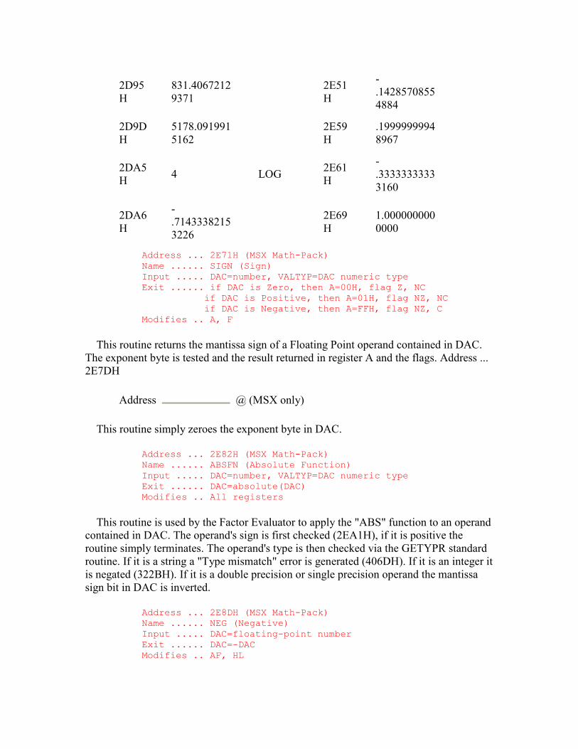
2D95H
831.40672129371 2E51
H
-.14285708554884
2D9DH
5178.0919915162 2E59
H .19999999948967
2DA5H 4 LOG 2E61
H
-.33333333333160
2DA6H
-.71433382153226
2E69H
1.0000000000000
Address ... 2E71H (MSX Math-Pack) Name ...... SIGN (Sign) Input ..... DAC=number, VALTYP=DAC numeric type Exit ...... if DAC is Zero, then A=00H, flag Z, NC if DAC is Positive, then A=01H, flag NZ, NC if DAC is Negative, then A=FFH, flag NZ, C Modifies .. A, F
This routine returns the mantissa sign of a Floating Point operand contained in DAC. The exponent byte is tested and the result returned in register A and the flags. Address ... 2E7DH
Address @ (MSX only)
This routine simply zeroes the exponent byte in DAC.
Address ... 2E82H (MSX Math-Pack) Name ...... ABSFN (Absolute Function) Input ..... DAC=number, VALTYP=DAC numeric type Exit ...... DAC=absolute(DAC) Modifies .. All registers
This routine is used by the Factor Evaluator to apply the "ABS" function to an operand contained in DAC. The operand's sign is first checked (2EA1H), if it is positive the routine simply terminates. The operand's type is then checked via the GETYPR standard routine. If it is a string a "Type mismatch" error is generated (406DH). If it is an integer it is negated (322BH). If it is a double precision or single precision operand the mantissa sign bit in DAC is inverted.
Address ... 2E8DH (MSX Math-Pack) Name ...... NEG (Negative) Input ..... DAC=floating-point number Exit ...... DAC=-DAC Modifies .. AF, HL

This routine changes the signal of Floating Point numbers. It does not check the DAC datum type in VALTYP, it assumes the number to be a floating-point, returns with no action if the value is zero, else changes the signal of the number by inverting the bit 7 of the first byte in DAC, which contains the number's signal.
Address ... 2E97H (MSX Math-Pack) Name ...... SGN (Signal) Input ..... DAC=number, VALTYP=DAC numeric type Exit ...... if DAC is Zero, then DAC=0000H, VALTYP=2 (integer) if DAC is Positive, then DAC=0001H, VALTYP=2 (integer) if DAC is Negative, then DAC=FFFFH, VALTYP=2 (integer) Modifies .. AF, HL
This routine is used by the Factor Evaluator to apply the "SGN" function to an operand contained in DAC. The operand's sign is checked (2EA1H), extended into register pair HL and then placed in DAC as an integer. Address ... 2EA1H
Address @ (MSX only)
This routine returns the sign of an operand contained in DAC. The operands type is first checked via the GETYPR standard routine. If it is a string a "Type mismatch" error is generated (406DH). If it is a single precision or double precision operand the mantissa sign is examined (2E71H). If it is an integer its value is taken from DAC+2 and translated into the flags shown at 2E71H. Address ... 2EB1H
Address @ (MSX only)
This routine pushes a four byte single precision operand from DAC onto the Z80 stack. Address ... 2EC1H
Address @ (MSX only)
This routine copies the contents of registers C, B, E and D to DAC. Address ... 2ECCH
Address @ (MSX only)
This routine copies the contents of DAC to registers C, B, E and D. Address ... 2ED6H
Address @ (MSX only)
This routine loads registers C, B, E and D from upwardly sequential locations starting at the address supplied in register pair HL. Address ... 2EDFH

Address @ (MSX only)
This routine loads registers E, D, C and B from upwardly sequential locations starting at the address supplied in register pair HL. Address ... 2EE8H
Address @ (MSX only)
This routine copies a single precision operand from DAC to the address supplied in register pair HL. Address ... 2EEFH
Address @ (MSX only)
This routine copies any operand from the address supplied in register pair HL to ARG. The length of the operand is contained in VALTYP: 2=Integer, 3=String, 4=Single Precision, 8=Double Precision. Address ... 2F05H
Address @ (MSX only)
This routine copies any operand from ARG to DAC. The length of the operand is contained in VALTYP: 2=Integer, 3=String, 4=Single Precision, 8=Double Precision. Address ... 2F0DH
Address @ (MSX only)
This routine copies any operand from DAC to ARG. The length of the operand is contained in VALTYP: 2=Integer, 3=String, 4=Single Precision, 8=Double Precision.
Address ... 2F21H Name ...... FCOMP (Single Precision Floating Point Comparison) Input ..... CBED=Operand 1, DAC=Operand 2 Exit ...... if CBED>DAC, then A=FFH (-1), Flag NZ, C if CBED=DAC, then A=00H (0), Flag Z, NC if CBED<DAC, then A=01H (1), Flag NZ, NC Modifies .. AF, HL
This routine is used by the Expression Evaluator to find the relation (<>=) between two single precision operands. The first operand is contained in registers C, B, E and D and the second in DAC. The result is returned in register A and the flags.
It should be noted that for relational operators the Expression Evaluator regards maximally negative numbers as small and maximally positive numbers as large.
Address ... 2F4DH (MSX Math-Pack) Name ...... ICOMP (Integer Comparison) Input ..... DE=Operand 1, HL=Operand 2
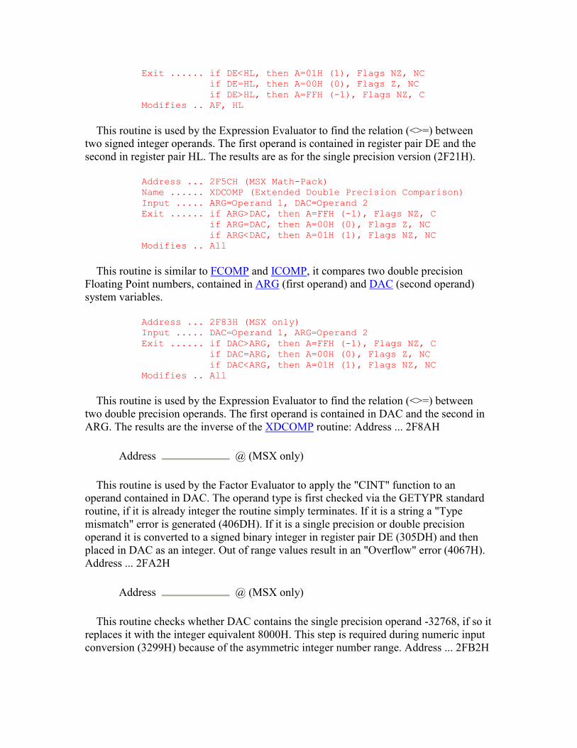
Exit ...... if DE<HL, then A=01H (1), Flags NZ, NC if DE=HL, then A=00H (0), Flags Z, NC if DE>HL, then A=FFH (-1), Flags NZ, C Modifies .. AF, HL
This routine is used by the Expression Evaluator to find the relation (<>=) between two signed integer operands. The first operand is contained in register pair DE and the second in register pair HL. The results are as for the single precision version (2F21H).
Address ... 2F5CH (MSX Math-Pack) Name ...... XDCOMP (Extended Double Precision Comparison) Input ..... ARG=Operand 1, DAC=Operand 2 Exit ...... if ARG>DAC, then A=FFH (-1), Flags NZ, C if ARG=DAC, then A=00H (0), Flags Z, NC if ARG<DAC, then A=01H (1), Flags NZ, NC Modifies .. All
This routine is similar to FCOMP and ICOMP, it compares two double precision Floating Point numbers, contained in ARG (first operand) and DAC (second operand) system variables.
Address ... 2F83H (MSX only) Input ..... DAC=Operand 1, ARG=Operand 2 Exit ...... if DAC>ARG, then A=FFH (-1), Flags NZ, C if DAC=ARG, then A=00H (0), Flags Z, NC if DAC<ARG, then A=01H (1), Flags NZ, NC Modifies .. All
This routine is used by the Expression Evaluator to find the relation (<>=) between two double precision operands. The first operand is contained in DAC and the second in ARG. The results are the inverse of the XDCOMP routine: Address ... 2F8AH
Address @ (MSX only)
This routine is used by the Factor Evaluator to apply the "CINT" function to an operand contained in DAC. The operand type is first checked via the GETYPR standard routine, if it is already integer the routine simply terminates. If it is a string a "Type mismatch" error is generated (406DH). If it is a single precision or double precision operand it is converted to a signed binary integer in register pair DE (305DH) and then placed in DAC as an integer. Out of range values result in an "Overflow" error (4067H). Address ... 2FA2H
Address @ (MSX only)
This routine checks whether DAC contains the single precision operand -32768, if so it replaces it with the integer equivalent 8000H. This step is required during numeric input conversion (3299H) because of the asymmetric integer number range. Address ... 2FB2H
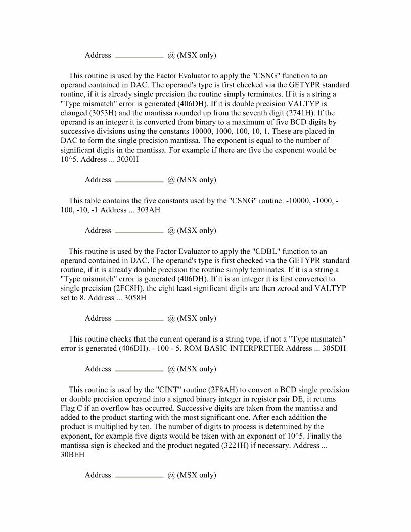
Address @ (MSX only)
This routine is used by the Factor Evaluator to apply the "CSNG" function to an operand contained in DAC. The operand's type is first checked via the GETYPR standard routine, if it is already single precision the routine simply terminates. If it is a string a "Type mismatch" error is generated (406DH). If it is double precision VALTYP is changed (3053H) and the mantissa rounded up from the seventh digit (2741H). If the operand is an integer it is converted from binary to a maximum of five BCD digits by successive divisions using the constants 10000, 1000, 100, 10, 1. These are placed in DAC to form the single precision mantissa. The exponent is equal to the number of significant digits in the mantissa. For example if there are five the exponent would be 10^5. Address ... 3030H
Address @ (MSX only)
This table contains the five constants used by the "CSNG" routine: -10000, -1000, -100, -10, -1 Address ... 303AH
Address @ (MSX only)
This routine is used by the Factor Evaluator to apply the "CDBL" function to an operand contained in DAC. The operand's type is first checked via the GETYPR standard routine, if it is already double precision the routine simply terminates. If it is a string a "Type mismatch" error is generated (406DH). If it is an integer it is first converted to single precision (2FC8H), the eight least significant digits are then zeroed and VALTYP set to 8. Address ... 3058H
Address @ (MSX only)
This routine checks that the current operand is a string type, if not a "Type mismatch" error is generated (406DH). - 100 - 5. ROM BASIC INTERPRETER Address ... 305DH
Address @ (MSX only)
This routine is used by the "CINT" routine (2F8AH) to convert a BCD single precision or double precision operand into a signed binary integer in register pair DE, it returns Flag C if an overflow has occurred. Successive digits are taken from the mantissa and added to the product starting with the most significant one. After each addition the product is multiplied by ten. The number of digits to process is determined by the exponent, for example five digits would be taken with an exponent of 10^5. Finally the mantissa sign is checked and the product negated (3221H) if necessary. Address ... 30BEH
Address @ (MSX only)
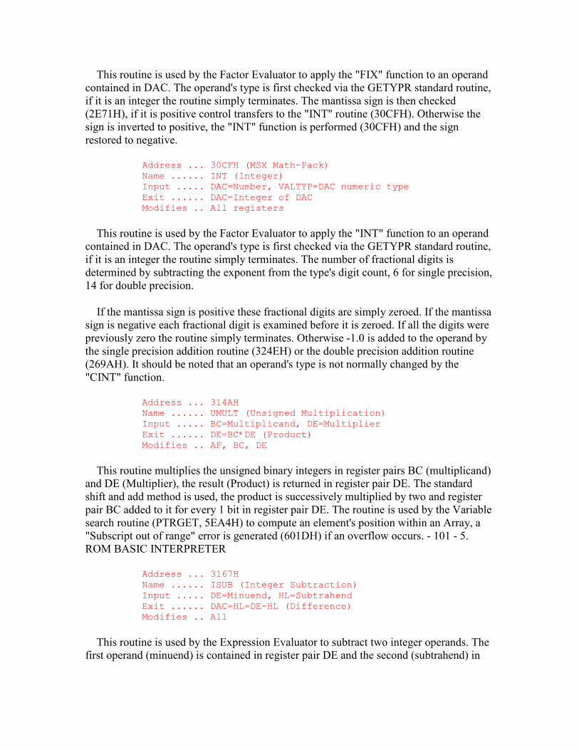
This routine is used by the Factor Evaluator to apply the "FIX" function to an operand contained in DAC. The operand's type is first checked via the GETYPR standard routine, if it is an integer the routine simply terminates. The mantissa sign is then checked (2E71H), if it is positive control transfers to the "INT" routine (30CFH). Otherwise the sign is inverted to positive, the "INT" function is performed (30CFH) and the sign restored to negative.
Address ... 30CFH (MSX Math-Pack) Name ...... INT (Integer) Input ..... DAC=Number, VALTYP=DAC numeric type Exit ...... DAC=Integer of DAC Modifies .. All registers
This routine is used by the Factor Evaluator to apply the "INT" function to an operand contained in DAC. The operand's type is first checked via the GETYPR standard routine, if it is an integer the routine simply terminates. The number of fractional digits is determined by subtracting the exponent from the type's digit count, 6 for single precision, 14 for double precision.
If the mantissa sign is positive these fractional digits are simply zeroed. If the mantissa sign is negative each fractional digit is examined before it is zeroed. If all the digits were previously zero the routine simply terminates. Otherwise -1.0 is added to the operand by the single precision addition routine (324EH) or the double precision addition routine (269AH). It should be noted that an operand's type is not normally changed by the "CINT" function.
Address ... 314AH Name ...... UMULT (Unsigned Multiplication) Input ..... BC=Multiplicand, DE=Multiplier Exit ...... DE=BC*DE (Product) Modifies .. AF, BC, DE
This routine multiplies the unsigned binary integers in register pairs BC (multiplicand) and DE (Multiplier), the result (Product) is returned in register pair DE. The standard shift and add method is used, the product is successively multiplied by two and register pair BC added to it for every 1 bit in register pair DE. The routine is used by the Variable search routine (PTRGET, 5EA4H) to compute an element's position within an Array, a "Subscript out of range" error is generated (601DH) if an overflow occurs. - 101 - 5. ROM BASIC INTERPRETER
Address ... 3167H Name ...... ISUB (Integer Subtraction) Input ..... DE=Minuend, HL=Subtrahend Exit ...... DAC=HL=DE-HL (Difference) Modifies .. All
This routine is used by the Expression Evaluator to subtract two integer operands. The first operand (minuend) is contained in register pair DE and the second (subtrahend) in
register pair HL, the result (difference) is returned in HL and DAC. The second operand is negated (3221H) and control drops into the addition routine.
Address ... 3172H Name ...... IADD (Integer Addition) Input ..... DE=Addend 1, HL=Addend 2 Exit ...... DAC=HL=DE+HL (Sum) Modifies .. AF, HL
This routine is used by the Expression Evaluator to add two integer operands. The first operand (addend 1) is contained in register pair DE and the second (addend 2) in register pair HL, the result is returned in DAC. The signed binary operands are normally just added and placed in DAC. However, if an overflow has occurred both operands are converted to single precision (2FCBH) and control transfers to the single precision adder (324EH). An overflow has occurred when both operands are of the same sign and the result is of the opposite sign, for example:
30000+15000=-20536
Address ... 3193H Address @ (MSX only)
This routine is used by the Expression Evaluator to multiply two integer operands. The first operand is contained in register pair DE and the second in register pair HL, the result is returned in DAC. The two operand signs are saved temporarily and both operands made positive (3215H). Multiplication proceeds using the standard binary shift and add method with register pair HL as the product accumulator, register pair BC containing the first operand and register pair DE the second. If the product exceeds 7FFFH at any time during multiplication both operands are converted to single precision (2FCBH) and control transfers to the single precision multiplier (325CH). Otherwise the initial signs are restored and, if they differ, the product negated before being placed in DAC as an integer (321DH). Address ... 31E6H
Address @ (MSX only)
This routine is used by the Expression Evaluator to integer divide (\) two integer operands. The first operand is contained in register pair DE and the second in register pair HL, the result is returned in DAC. If the second operand is zero a "Division by zero" error is generated (4058H), otherwise the two operand signs are saved and both operands made positive (3215H). Division proceeds using the standard binary shift and subtract method with register pair HL containing the remainder, register pair BC the second operand and register pair DE the first operand and the product. When division is complete the initial signs are restored and, if they differ, the product is negated before being placed in DAC as an integer (321DH). - 102 - 5. ROM BASIC INTERPRETER Address ... 3215H
Address @ (MSX only)
This routine is used to make two signed binary integers, in register pairs HL and DE, positive. Both the initial operand signs are returned as a flag in bit 7 of register B: 0=Same, 1=Different. Each operand is then examined and, if it is negative, made positive by subtracting it from zero. Address ... 322BH
Address @ (MSX only)
This routine is used by the "ABS" function to make a negative integer contained in DAC positive. The operand is taken from DAC, negated and then placed back in DAC (3221H). If the operand's value is 8000H it is converted to single precision (2FCCH) as there is no integer of value +32768. Address ... 323AH
Address @ (MSX only)
This routine is used by the Expression Evaluator to "MOD" two integer operands. The first operand is contained in register pair DE and the second in register pair HL, the result is returned in DAC. The sign of the first operand is saved and the two operands divided (31E6H). As the remainder is returned doubled by the division process register pair DE is shifted one place right to restore it. The sign of the first operand is then restored and, if it is negative, the remainder is negated before being placed in DAC as an integer (321DH). Address ... 324EH
Address @ (MSX only)
This routine is used by the Expression Evaluator to add two single precision operands. The first operand is contained in registers C, B, E, D and the second in DAC, the result is returned in DAC. The first operand is copied to ARG (3280H), the second operand is converted to double precision (3042H) and control transfers to the double precision adder (269AH). Address ... 3257H
Address @ (MSX only)
This routine is used by the Expression Evaluator to subtract two single precision operands. The first operand is contained in registers C, B, E, D and the second in DAC, the result is returned in DAC. The second operand is negated (2E8DH) and control transfers to the single precision adder (324EH). Address ... 325CH
Address @ (MSX only)
This routine is used by the Expression Evaluator to multiply two single precision operands. The first operand is contained in registers C, B, E, D and the second in DAC, the result is returned in DAC. The first operand is copied to ARG (3280H), the second operand is converted to double precision (3042H) and control transfers to the double precision multiplier (27E6H). - 103 - 5. ROM BASIC INTERPRETER Address ... 3265H

Address @ (MSX only)
This routine is used by the Expression Evaluator to divide two single precision operands. The first operand is contained in registers C, B, E, D and the second in DAC, the result is returned in DAC. The first and second operands are exchanged so that the first is in DAC and the second in the registers. The second operand is then copied to ARG (3280H), the first operand is converted to double precision (3042H) and control transfers to the double precision divider (289FH). Address ... 3280H
Address @ (MSX only)
This routine copies the single precision operand contained in registers C, B, E and D to ARG and then zeroes the four least significant bytes. Address ... 3299H
Address @ (MSX only)
This routine converts a number in textual form to one of the standard internal numeric types, it is used during tokenization and by the "VAL", "INPUT" and "READ" Statement handlers. On entry register pair HL points to the first character of the text string to be converted. On exit register pair HL points to the character following the string, the numeric operand is in DAC and the type code in VALTYP. Examples of the three types are:
+-----+-----+-----+-----+-----+-----+-----+-----+ | | | FFH | 7FH | | | | | +-----+-----+-----+-----+-----+-----+-----+-----+ Integer +32767 +-----+-----+-----+-----+-----+-----+-----+-----+ | 42H | 17H | 39H | 04H | | | | | +-----+-----+-----+-----+-----+-----+-----+-----+ Single Precision .173904*10^2 +-----+-----+-----+-----+-----+-----+-----+-----+ | C2H | 17H | 39H | 04H | 62H | 70H | 93H | 13H | +-----+-----+-----+-----+-----+-----+-----+-----+ Double Precision -.17390462709313*10^2
Figure 41: Numeric Types in DAC.
An integer is a sixteen bit binary number in two's complement form, it is stored LSB first, MSB second at DAC+2. An integer can range from 8000H (-32768) to 7FFFH (+32767).
A floating point number consists of an exponent byte and a three or seven byte mantissa. The exponent is kept in signed binary form and can range from 01H (-63) through 40H (0) up to 7FH (+63), the special value of 00H is used for the number zero. These exponent values are for a normalized mantissa. The Interpreter presents exponent-
form numbers to the user with a leading digit, this results in an asymmetric exponent range of E-64 to E+62. Bit 7 of the exponent byte holds the mantissa sign, 0 for positive and 1 for negative, the mantissa itself is kept in packed BCD form with two digits per byte. It should be noted that the Interpreter uses the contents of VALTYP to determine a number's type, not the format of the number itself.
Conversion starts by examining the first text character. If this is an "&" control transfers to the special radix conversion routine (4EB8H), if it is a leading sign character it is temporarily saved. Successive numeric characters are then taken and added to the integer product with appropriate multiplications by ten as each new digit is found. If the value of the product exceeds 32767, or a decimal point is found, the product is converted to single precision and any further characters placed directly in DAC. If a seventh digit is found the product is changed to double precision, if more than fourteen digits are found the excess digits are read but ignored.
Conversion ceases when a non-numeric character is found. If this a type definition character ("%", "#" or "!") the appropriate conversion routine is called and control transfers to the exit point (331EH). If it is an exponent prefix ("E", "e", "D" or "d") one of the conversion routines will also be used and then the following digits converted to a binary exponent in register E. At the exit point (331EH) the product's type is checked via the GETYPR standard routine. If it is single precision or double precision the exponent is calculated by first subtracting the fractional digit count, in register B, from the total digit count, in register D, to produce the leading digit count. This is then added to any explicitly stated exponent, in register E, and placed at DAC+0 as the exponent.
The leading sign character is restored and the product negated if required (2E86H), if the product is integer the routine then terminates. If the product is single precision control terminates by checking for the special value of -32768 (2FA2H). If the product is double precision control terminates by rounding up from the fifteenth digit (273CH). Address ... 340AH
Address @ (MSX only)
This routine is used by the error handler to display the message " in " (6678H) followed by the line number supplied in register pair HL (3412H). Address ... 3412H
Address @ (MSX only)
This routine displays the unsigned binary integer supplied in register pair HL. The operand is placed in DAC as an integer (2F99H), converted to text (3441H) and then displayed (6677H). - 105 - 5. ROM BASIC INTERPRETER Address ... 3425H
Address @ (MSX only)
This routine converts the numeric operand contained in DAC to textual form in FBUFFR. The address of the first character of the resulting text is returned in register pair HL, the text is terminated by a zero byte. The operand is first converted to double precision (375FH). The BCD digits of the mantissa are then unpacked, converted to ASCII and placed in FBUFFR (36B3H). The position of the decimal point is determined by the exponent, for example:
.999*10 ^ +2 = 99.9 .999*10 ^ +1 = 9.99 .999*10 ^ +0 = .999 .999*10 ^ -1 = .0999
If the exponent is outside the range 10^-1 to 10^14 the number is presented in exponential form. In this case the decimal point is placed after the first digit and the exponent is converted from binary and follows the mantissa.
An alternative entry point to the routine exists at 3426H for the "PRINT USING" statement handler. With this entry point the number of characters to prefix the decimal point is supplied in register B, the number of characters to point fix it in register C and a format byte in register A:
7 6 5 4 3 2 1 0 +-----+-----+-----+-----+-----+-----+-----+-----+ | 1 | , | * | $ | + |Sign | 0 |^^^^ | +-----+-----+-----+-----+-----+-----+-----+-----+
Figure 42: Format Byte.
Operation in this mode is fairly similar to the normal mode but with the addition of extra facilities. Once the operand has been converted to double precision the exponential form will be assumed if bit 0 of the format byte is set. The mantissa is shifted to the right in DAC and rounded up to lose unwanted postfix digits (377BH). As the mantissa is converted to ASCII (36B3H) commas will be inserted at the appropriate points if bit 6 of the format byte is set. During post-conversion formatting (351CH) unused prefix positions will be filled with asterisks if bit 5 is set, a pound prefix may be added by setting bit 4. Bit 3 enables the "+" sign for positive numbers if set, otherwise a space is used. Bit 2 places any sign at the front if reset and at the back if set.
The entry point to the routine at 3441H is used to convert unsigned integers, notably line numbers, to their textual form. For example 9000H, when treated as a normal integer, would be converted to -28672. By using this entry point 36864 would be produced instead. The operand is converted by successive division with the factors 10000, 1000, 100, 10 and 1 and the resulting digits placed in FBUFFR (36DBH). Address ... 3710H
Address @ (MSX only)

This table contains the five constants used by the numeric output routine: 10000, 1000, 100, 10, 1. Address ... 371AH
Address @ (MSX only)
This routine is used by the "BIN$" function to convert a numeric operand contained in DAC to textual form. Register B is loaded with the group size (1) and control transfers to the general conversion routine (3724H). Address ... 371EH
Address @ (MSX only)
This routine is used by the "OCT$" function to convert a numeric operand contained in DAC to textual form. Register B is loaded with the group size (3) and control transfers to the general conversion routine (3724H). Address ... 3722H
Address @ (MSX only)
This routine is used by the "HEX$" function to convert a numeric operand contained in DAC to textual form. Register B is loaded with the group size (4) and the operand converted to a binary integer in register pair HL (5439H). Successive groups of 1, 3 or 4 bits are shifted rightwards out of the operand, converted to ASCII digits and placed in FBUFFR. When the operand is all zeroes the routine terminates with the address of the first text character in register pair HL, the string is terminated with a zero byte. Address ... 3752H
Address @ (MSX only)
This routine is used during numeric output to return an operand's digit count in register B and the address of its least significant byte in register pair HL. For single precision B=6 and HL=DAC+3, for double precision B=14 and HL=DAC+7. Address ... 375FH
Address @ (MSX only)
This routine is used during numeric output to convert the numeric operand in DAC to double precision (303AH). Address ... 377BH
Address @ (MSX only)
This routine is used during numeric output to shift the mantissa in DAC rightwards (27DBH), the inverse of the digit count is supplied in register A. The result is then rounded up from the fifteenth digit (2741H). - 107 - 5. ROM BASIC INTERPRETER Address ... 37A2H
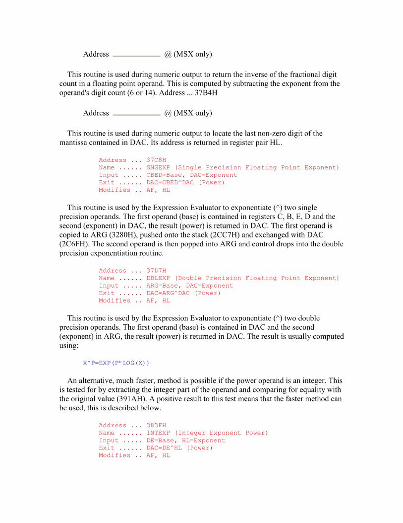
Address @ (MSX only)
This routine is used during numeric output to return the inverse of the fractional digit count in a floating point operand. This is computed by subtracting the exponent from the operand's digit count (6 or 14). Address ... 37B4H
Address @ (MSX only)
This routine is used during numeric output to locate the last non-zero digit of the mantissa contained in DAC. Its address is returned in register pair HL.
Address ... 37C8H Name ...... SNGEXP (Single Precision Floating Point Exponent) Input ..... CBED=Base, DAC=Exponent Exit ...... DAC=CBED^DAC (Power) Modifies .. AF, HL
This routine is used by the Expression Evaluator to exponentiate (^) two single precision operands. The first operand (base) is contained in registers C, B, E, D and the second (exponent) in DAC, the result (power) is returned in DAC. The first operand is copied to ARG (3280H), pushed onto the stack (2CC7H) and exchanged with DAC (2C6FH). The second operand is then popped into ARG and control drops into the double precision exponentiation routine.
Address ... 37D7H Name ...... DBLEXP (Double Precision Floating Point Exponent) Input ..... ARG=Base, DAC=Exponent Exit ...... DAC=ARG^DAC (Power) Modifies .. AF, HL
This routine is used by the Expression Evaluator to exponentiate (^) two double precision operands. The first operand (base) is contained in DAC and the second (exponent) in ARG, the result (power) is returned in DAC. The result is usually computed using:
X^P=EXP(P*LOG(X))
An alternative, much faster, method is possible if the power operand is an integer. This is tested for by extracting the integer part of the operand and comparing for equality with the original value (391AH). A positive result to this test means that the faster method can be used, this is described below.
Address ... 383FH Name ...... INTEXP (Integer Exponent Power) Input ..... DE=Base, HL=Exponent Exit ...... DAC=DE^HL (Power) Modifies .. AF, HL
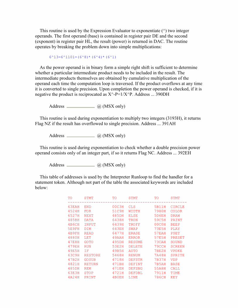
This routine is used by the Expression Evaluator to exponentiate (^) two integer operands. The first operand (base) is contained in register pair DE and the second (exponent) in register pair HL, the result (power) is returned in DAC. The routine operates by breaking the problem down into simple multiplications:
6^13=6^1101=(6^8)*(6^4)*(6^1)
As the power operand is in binary form a simple right shift is sufficient to determine whether a particular intermediate product needs to be included in the result. The intermediate products themselves are obtained by cumulative multiplication of the operand each time the computation loop is traversed. If the product overflows at any time it is converted to single precision. Upon completion the power operand is checked, if it is negative the product is reciprocated as X^-P=1/X^P. Address ... 390DH
Address @ (MSX only)
This routine is used during exponentiation to multiply two integers (3193H), it returns Flag NZ if the result has overflowed to single precision. Address ... 391AH
Address @ (MSX only)
This routine is used during exponentiation to check whether a double precision power operand consists only of an integer part, if so it returns Flag NC. Address ... 392EH
Address @ (MSX only)
This table of addresses is used by the Interpreter Runloop to find the handler for a statement token. Although not part of the table the associated keywords are included below:
TO STMT TO STMT TO STMT --------------------------------------------------- 63EAH END 00C3H CLS 5B11H CIRCLE 4524H FOR 51C9H WIDTH 7980H COLOR 6527H NEXT 485DH ELSE 5D6EH DRAW 485BH DATA 6438H TRON 59C5H PAINT 4B6CH INPUT 6439H TROFF 00C0H BEEP 5E9FH DIM 643EH SWAP 73E5H PLAY 4B9FH READ 6477H ERASE 57EAH PSET 4880H LET 49AAH ERROR 57E5H PRESET 47E8H GOTO 495DH RESUME 73CAH SOUND 479EH RUN 53E2H DELETE 79CCH SCREEN 49E5H IF 49B5H AUTO 7BE2H VPOKE 63C9H RESTORE 5468H RENUM 7A48H SPRITE 47B2H GOSUB 4718H DEFSTR 7B37H VDP 4821H RETURN 471BH DEFINT 7B5AH BASE 485DH REM 471EH DEFSNG 55A8H CALL 63E3H STOP 4721H DEFDBL 7911H TIME 4A24H PRINT 4B0EH LINE 786CH KEY

64AFH CLEAR 6AB7H OPEN 7E4BH MAX 522EH LIST 7C52H FIELD 73B7H MOTOR 6286H NEW 775BH GET 6EC6H BLOAD 48E4H ON 7758H PUT 6E92H BSAVE 401CH WAIT 6C14H CLOSE 7C16H DSKO$ 501DH DEF 6B5DH LOAD 7C1BH SET 5423H POKE 6B5EH MERGE 7C20H NAME 6424H CONT 6C2FH FILES 7C25H KILL 6FB7H CSAVE 7C48H LSET 7C2AH IPL 703FH CLOAD 7C4DH RSET 7C2FH COPY 4016H OUT 6BA3H SAVE 7C34H CMD 4A1DH LPRINT 6C2AH LFILES 7766H LOCATE 5229H LLIST
- 109 - 5. ROM BASIC INTERPRETER Address ... 39DEH Address @ (MSX only)
This table of addresses is used by the Factor Evaluator to find the handler for a function token. Although not part of the table the associated keywords are included with the addresses shown below:
TO FUNCTION TO FUNCTION TO FUNCTION ------------------------------------------------------- 6861H LEFT$ 4FCCH POS 30BEH FIX 6891H RIGHT$ 67FFH LEN 7940H STICK 689AH MID$ 6604H TR$ 794CH TRIG 2E97H SGN 68BBH VAL 795AH PDL 30CFH INT 680BH ASC 7969H PAD 2E82H ABS 681BH CHR$ 7C39H DSKF 2AFFH SQR 541CH PEEK 6D39H FPOS 2BDFH RND 7BF5H VPEEK 7C66H CVI 29ACH SIN 6848H SPACE$ 7C6BH CVS 2A72H LOG 7C70H OCT$ 7C70H CVD 2B4AH EXP 65FAH HEX$ 6D25H EOF 2993H COS 4FC7H LPOS 6D03H LOC 29FBH TAN 6FFFH BIN$ 6D14H LOF 2A14H ATN 2F8AH CINT 7C57H MKI$ 69F2H FRE 2FB2H CSNG 7C5CH MKS$ 4001H INP 303AH CDBL 7C61H MKD$
Address ... 3A3EH Address @ (MSX only)
This table of addresses is used during program tokenization as an index into the BASIC keyword table (3A72H). Each of the twenty six entries defines the starting address of one of the keyword sub-blocks. The first entry points to the keywords beginning with the letter "A", the second to those beginning with the letter "B" and so on.
3A72H ... A 3B9FH ... J 3C8EH ... S 3A88H ... B 3BA0H ... K 3CDBH ... T 3A9FH ... C 3BA8H ... L 3CF6H ... U 3AF3H ... D 3BE8H ... M 3CFFH ... V 3B2EH ... E 3C09H ... N 3D16H ... W 3B4FH ... F 3C18H ... O 3D20H ... X

3B69H ... G 3C2BH ... P 3D24H ... Y 3B7BH ... H 3C5DH ... Q 3D25H ... Z 3B80H ... I 3C5EH ... R
Address ... 3A72H Address @ (MSX only)
This table contains the BASIC keywords and tokens. Each of the twenty-six blocks within the table contains all the keywords beginning with a particular letter, it is terminated with a zero byte. Each keyword is stored in plain text with bit 7 set to mark the last character, this is followed immediately by the associated token. The first character of the keyword need not be stored as this is implied by its position in the table' The keywords and tokens are listed below in full, note that the "J", "Q", "Y" and "Z" blocks are empty:
AUTO A9H DSKF 26H LIST 93H REM 8FH AND F6H DRAW BEH LFILES BBH RESUME A7H ABS 06H ELSE A1H LOG 0AH RSET B9H ATN 0EH END 81H LOC 2CH RIGHT$ 02H ASC 15H ERASE A5H LEN 12H RND 08H ATTR$ E9H ERROR A6H LEFT$ 01H RENUM AAH BASE C9H ERL E1H LOF 2DH SCREEN C5H BSAVE D0H ERR E2H MOTOR CEH SPRITE C7H BLOAD CFH EXP 0BH MERGE B6H STOP 90H BEEP C0H EOF 2BH MOD FBH SWAP A4H BIN$ 1DH EQV F9H MKI$ 2EH SET D2H CALL CAH FOR 82H MKS$ 2FH SAVE BAH CLOSE B4H FIELD B1H MKD$ 30H SPC( DFH COPY D6H FILES B7H MID$ 03H STEP DCH CONT 99H FN DEH MAX CDH SGN 04H CLEAR 92H FRE 0FH NEXT 83H SQR 07H CLOAD 9BH FIX 21H NAME D3H SIN 09H CSAVE 9AH FPOS 27H NEW 94H STR$ 13H CSRLIN E8H GOTO 89H NOT E0H STRING$ E3H CINT 1EH GO TO 89H OPEN B0H SPACE$ 19H CSNG 1FH GOSUB 8DH OUT 9CH SOUND C4H CDBL 20H GET B2H ON 95H STICK 22H CVI 28H HEX$ 1BH OR F7H STRIG 23H CVS 29H INPUT 85H OCT$ 1AH THEN DAH CVD 2AH IF 8BH OFF EBH TRON A2H COS 0CH INSTR E5H PRINT 91H TROFF A3H CHR$ 16H INT 05H PUT B3H TAB( DBH CIRCLE BCH INP 10H POKE 98H TO D9H COLOR BDH IMP FAH POS 11H TIME CBH CLS 9FH INKEY$ ECH PEEK 17H TAN 0DH CMD D7H IPL D5H PSET C2H USING E4H DELETE A8H KILL D4H PRESET C3H USR DDH DATA 84H KEY CCH POINT EDH VAL 14H DIM 86H LPRINT 9DH PAINT BFH VARPTR E7H DEFSTR ABH LLIST 9EH PDL 24H VDP C8H DEFINT ACH LPOS 1CH PAD 25H VPOKE C6H DEFSNG ADH LET 88H PLAY C1H VPEEK 18H DEFDBL AEH LOCATE D8H RETURN 8EH WIDTH A0H DSKO$ D1H LINE AFH READ 87H WAIT 96H DEF 97H LOAD B5H RUN 8AH XOR F8H
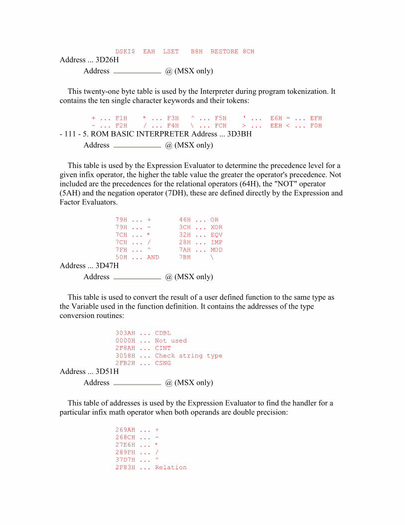
DSKI$ EAH LSET B8H RESTORE 8CH
Address ... 3D26H Address @ (MSX only)
This twenty-one byte table is used by the Interpreter during program tokenization. It contains the ten single character keywords and their tokens:
+ ... F1H * ... F3H ^ ... F5H ' ... E6H = ... EFH - ... F2H / ... F4H \ ... FCH > ... EEH < ... F0H
- 111 - 5. ROM BASIC INTERPRETER Address ... 3D3BH Address @ (MSX only)
This table is used by the Expression Evaluator to determine the precedence level for a given infix operator, the higher the table value the greater the operator's precedence. Not included are the precedences for the relational operators (64H), the "NOT" operator (5AH) and the negation operator (7DH), these are defined directly by the Expression and Factor Evaluators.
79H ... + 46H ... OR 79H ... - 3CH ... XOR 7CH ... * 32H ... EQV 7CH ... / 28H ... IMP 7FH ... ^ 7AH ... MOD 50H ... AND 7BH \
Address ... 3D47H Address @ (MSX only)
This table is used to convert the result of a user defined function to the same type as the Variable used in the function definition. It contains the addresses of the type conversion routines:
303AH ... CDBL 0000H ... Not used 2F8AH ... CINT 3058H ... Check string type 2FB2H ... CSNG
Address ... 3D51H Address @ (MSX only)
This table of addresses is used by the Expression Evaluator to find the handler for a particular infix math operator when both operands are double precision:
269AH ... + 268CH ... - 27E6H ... * 289FH ... / 37D7H ... ^ 2F83H ... Relation
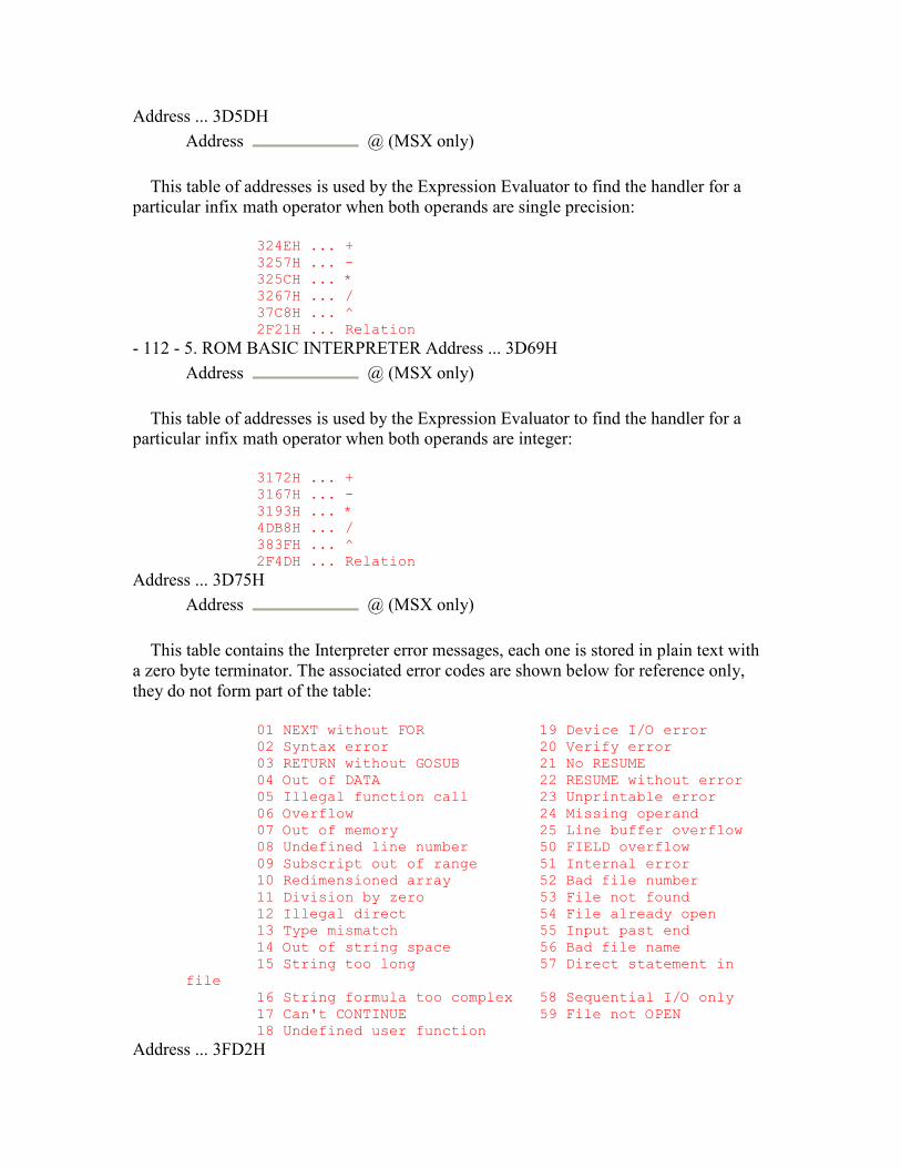
Address ... 3D5DH Address @ (MSX only)
This table of addresses is used by the Expression Evaluator to find the handler for a particular infix math operator when both operands are single precision:
324EH ... + 3257H ... - 325CH ... * 3267H ... / 37C8H ... ^ 2F21H ... Relation
- 112 - 5. ROM BASIC INTERPRETER Address ... 3D69H Address @ (MSX only)
This table of addresses is used by the Expression Evaluator to find the handler for a particular infix math operator when both operands are integer:
3172H ... + 3167H ... - 3193H ... * 4DB8H ... / 383FH ... ^ 2F4DH ... Relation
Address ... 3D75H Address @ (MSX only)
This table contains the Interpreter error messages, each one is stored in plain text with a zero byte terminator. The associated error codes are shown below for reference only, they do not form part of the table:
01 NEXT without FOR 19 Device I/O error 02 Syntax error 20 Verify error 03 RETURN without GOSUB 21 No RESUME 04 Out of DATA 22 RESUME without error 05 Illegal function call 23 Unprintable error 06 Overflow 24 Missing operand 07 Out of memory 25 Line buffer overflow 08 Undefined line number 50 FIELD overflow 09 Subscript out of range 51 Internal error 10 Redimensioned array 52 Bad file number 11 Division by zero 53 File not found 12 Illegal direct 54 File already open 13 Type mismatch 55 Input past end 14 Out of string space 56 Bad file name 15 String too long 57 Direct statement in file 16 String formula too complex 58 Sequential I/O only 17 Can't CONTINUE 59 File not OPEN 18 Undefined user function
Address ... 3FD2H

Address @ (MSX only)
This is the plain text message " in " terminated by a zero byte. Address ... 3FD7H
Address @ (MSX only)
This is the plain text message "Ok", CR, LF terminated by a zero byte. Address ... 3FDCH
Address @ (MSX only)
This is the plain text message "Break" terminated by a zero byte. - 113 - 5. ROM BASIC INTERPRETER Address ... 3FE2H
Address @ (MSX only)
This routine searches the Z80 stack for the "FOR" loop parameter block whose loop Variable address is supplied in register pair DE. The search is started four bytes above the current Z80 SP to allow for the caller's return address and the Runloop return address. If no "FOR" token (82H) exists the routine terminates Flag NZ, if one is found the loop Variable address is taken from the parameter block and checked. The routine terminates Flag Z upon a successful match with register pair HL pointing to the type byte of the parameter block. Otherwise the search moves up twenty-two bytes to the start of the next parameter block. Address ... 4001H
Address @ (MSX only)
This routine is used by the Factor Evaluator to apply the "INP" function to an operand contained in DAC. The port number is checked (5439H), the port read and the result placed in DAC as an integer (4FCFH). Address ... 400BH
Address @ (MSX only)
This routine first evaluates an operand in the range -32768 to +65535 (FRMQNT, 542FH) and places it in register pair BC. After checking for a comma, via the SYNCHR standard routine, it evaluates a second operand in the range 0 to 255 (GETBYT, 521CH) and places this in register A. Address ... 4016H
Address @ (MSX only)
This is the "OUT" statement handler. The port number and data byte are evaluated (400BH) and the data byte written to the relevant Z80 port. Address ... 401CH
Address @ (MSX only)
This is the "WAIT" statement handler. The port number and "AND" operands are first evaluated (400BH) followed by the optional "XOR" operand (GETBYT, 521CH). The port is then repeatedly read and the operands applied, XOR then AND, until a non-zero result is obtained. Contrary to the information given in some MSX manuals the loop can be broken by the CTRL-STOP key as the CKCNTC standard routine is called from inside it. Address ... 4039H
Address @ (MSX only)
This routine is used by the Runloop when it encounters the end of the program text while in program mode. ONEFLAG is checked to see whether it still contains an active error code. If so a "No RESUME" error is generated, otherwise program termination continues normally (6401H). The idea behind this routine is to catch any "ON ERROR" handlers without a "RESUME" statement at the end. - 114 - 5. ROM BASIC INTERPRETER Address ... 404FH
Address @ (MSX only)
This routine is used by the "READ" statement handler when an error is found in a "DATA" statement. The line number contained in DATLIN is copied to CURLIN so the error handler will flag the "DATA" line as the illegal statement rather than the program line. Control then drops into the "Syntax error" generator. Address ... 4055H
Address @ (MSX only)
This is a group of nine error generators, register E is loaded with the relevant error code and control drops into the error handler:
ADDR. ERROR ------------------------------- 4055H Syntax error 4058H Division by zero 405BH NEXT without FOR 405EH Redimensioned array 4061H Undefined user function 4064H RESUME without error 4067H Overflow error 406AH Missing operand 406DH Type mismatch
Address ... 406FH Address @ (MSX only)
This is the Interpreter error handler, all error generators transfer to here with an error code in register E. VLZADR is first checked to see if the "VAL" statement handler has
changed the program text, if so the original character is restored from VLZDAT. The current line number is then copied from CURLIN to ERRLIN and DOT and the Z80 stack is restored from SAVSTK (62F0H). The error code is placed in ERRFLG, for use by the "ERR" function, and the current program text position copied from SAVTXT to ERRTXT for use by the "RESUME" statement handler. The error line number and program text position are also copied to OLDLIN and OLDTXT for use by the "CONT" statement handler. ONELIN is then checked to see if a previous "ON ERROR" statement has been executed. If so, and providing no error code is already active, control transfers to the Runloop (4620H) to execute the BASIC error recovery statements.
Otherwise the error code is used to count through the error message table at 3D75H until the required one is reached. A CR,LF is issued (7323H) and the screen forced back to text mode via the TOTEXT standard routine. A BELL code is then issued and the error message displayed (6678H). Assuming the Interpreter is in program mode, rather than direct mode, this is followed by the line number (340AH) and control drops into the "OK" point. - 115 - 5. ROM BASIC INTERPRETER Address ... 411FH
Address @ (MSX only)
This is the re-entry point to the Interpreter Mainloop for a terminating program. The screen is forced to text mode via the TOTEXT standard routine, the printer is cleared (7304H) and I/O buffer 0 closed (6D7BH). A CR,LF is then issued to the screen (7323H), the message "OK" is displayed (6678H) and control drops into the Mainloop. Address ... 4134H
Address @ (MSX only)
This is the Interpreter Mainloop. CURLIN is first set to FFFFH to indicate direct mode and AUTFLG checked to see if "AUTO" mode is on. If so the next line number is taken from AUTLIN and displayed (3412H). The Program Text Area is then searched to see if this line already exists (4295H) and either an asterisk or space displayed accordingly.
The ISFLIO standard routine is then used to determine whether a "LOAD" statement is active. If so the program line is collected from the cassette (7374H), otherwise it is taken from the console via the PINLIN standard routine. If the line is empty or the CTRL-STOP key has been pressed control transfers back to the start of the Mainloop (4134H) with no further action. If the line commences with a line number this is converted to an unsigned integer in register pair DE (4769H). The line is then converted to tokenized form and placed in KBUF (CRUNCH, 42B2H). If no line number was found at the start of the line control then transfers to the Runloop (6D48H) to execute the statement.
Assuming the line commences with a line number it is tested to see if it is otherwise empty and the result temporarily saved. The line number is copied to DOT and AUTLIN increased by the contents of AUTINC, if AUTLIN now exceeds 65530 the "AUTO" mode is turned off. The Program Text Area is then searched (4295H) to find a matching
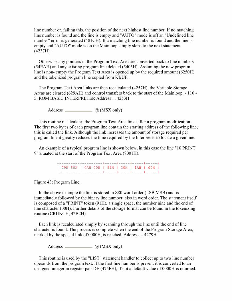
line number or, failing this, the position of the next highest line number. If no matching line number is found and the line is empty and "AUTO" mode is off an "Undefined line number" error is generated (481CH). If a matching line number is found and the line is empty and "AUTO" mode is on the Mainloop simply skips to the next statement (4237H).
Otherwise any pointers in the Program Text Area are converted back to line numbers (54EAH) and any existing program line deleted (5405H). Assuming the new program line is non- empty the Program Text Area is opened up by the required amount (6250H) and the tokenized program line copied from KBUF.
The Program Text Area links are then recalculated (4257H), the Variable Storage Areas are cleared (629AH) and control transfers back to the start of the Mainloop. - 116 - 5. ROM BASIC INTERPRETER Address ... 4253H
Address @ (MSX only)
This routine recalculates the Program Text Area links after a program modification. The first two bytes of each program line contain the starting address of the following line, this is called the link. Although the link increases the amount of storage required per program line it greatly reduces the time required by the Interpreter to locate a given line.
An example of a typical program line is shown below, in this case the line "10 PRINT 9" situated at the start of the Program Text Area (8001H):
+---------+---------+-----+-----+-----+-----+ | 09H 80H | 0AH 00H | 91H | 20H | 1AH | 00H | +---------+---------+-----+-----+-----+-----+
Figure 43: Program Line.
In the above example the link is stored in Z80 word order (LSB,MSB) and is immediately followed by the binary line number, also in word order. The statement itself is composed of a "PRINT" token (91H), a single space, the number nine and the end of line character (00H). Further details of the storage format can be found in the tokenizing routine (CRUNCH, 42B2H).
Each link is recalculated simply by scanning through the line until the end of line character is found. The process is complete when the end of the Program Storage Area, marked by the special link of 0000H, is reached. Address ... 4279H
Address @ (MSX only)
This routine is used by the "LIST" statement handler to collect up to two line number operands from the program text. If the first line number is present it is converted to an unsigned integer in register pair DE (475FH), if not a default value of 0000H is returned.
If the second line number is present it must be preceded by a "-" token (F2H) and is returned on the Z80 stack, if not a default value of 65530 is returned. Control then drops into the program text search routine to find the first referenced program line. Address ... 4295H
Address @ (MSX only)
This routine searches the Program Text Area for the program line whose line number is supplied in register pair DE. Starting at the address contained in TXTTAB each program line is examined for a match. If an equal line number is found the routine terminates with Flag Z and C and register pair BC pointing to the start of the program line. If a higher line number is found the routine terminates Flag NZ and NC and if the end link is reached the routine terminates Flag Z and NC. - 117 - 5. ROM BASIC INTERPRETER
Address ... 42B2H Name ...... CRUNCH (Crunch) Input ..... HL=ASCII text address (ended by 00H) Exit ...... KBUF=tokenized line Modifies .. All registers
This routine is used by the Interpreter Mainloop to tokenize a line of text. On entry register pair HL points to the first text character in BUF. On exit the tokenized line is in KBUF, register pair BC holds its length and register pair HL points to its start.
Except after opening quotes or after the "REM", "CALL" or "DATA" keywords any string of characters matching a keyword is replaced by that keyword's token. Lower case alphabetics are changed to upper case for keyword comparison. The character "?" is replaced by the "PRINT" token (91H) and the character "'" by ":" (3AH), "REM" token (8FH), "'" token (E6H). The "ELSE" token (A1H) is preceded by a statement separator (3AH). Any other miscellaneous characters in the text are copied without alteration except that lower case alphabetics are converted to upper case. Those tokens smaller than 80H, the function tokens, cannot be stored directly in KBUF as they will conflict with ordinary text. Instead the sequence FFH, token+80H is used.
Numeric constants are first converted into one of the standard types in DAC (3299H). They are then stored in one of several ways depending upon their type and magnitude, the general idea being to minimize memory usage:
0BH LSB MSB ................... Octal number 0CH LSB MSB ................... Hex number 11H to 1AH .................... Integer 0 to 9 0FH LSB ....................... Integer 10 to 255 1CH LSB MSB ................... Integer 256 to 32767 1DH EE DD DD DD ............... Single Precision 1FH EE DD DD DD DD DD DD DD ... Double Precision
There is no specific token for binary numbers, these are left as character strings. This would appear to be a legacy from earlier versions of Microsoft BASIC. Any sign
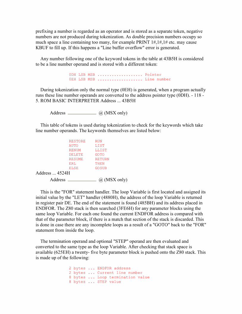
prefixing a number is regarded as an operator and is stored as a separate token, negative numbers are not produced during tokenization. As double precision numbers occupy so much space a line containing too many, for example PRINT 1#,1#,1# etc. may cause KBUF to fill up. If this happens a "Line buffer overflow" error is generated.
Any number following one of the keyword tokens in the table at 43B5H is considered to be a line number operand and is stored with a different token:
0DH LSB MSB ................... Pointer 0EH LSB MSB ................... Line number
During tokenization only the normal type (0EH) is generated, when a program actually runs these line number operands are converted to the address pointer type (0DH). - 118 - 5. ROM BASIC INTERPRETER Address ... 43B5H
Address @ (MSX only)
This table of tokens is used during tokenization to check for the keywords which take line number operands. The keywords themselves are listed below:
RESTORE RUN AUTO LIST RENUM LLIST DELETE GOTO RESUME RETURN ERL THEN ELSE GOSUB
Address ... 4524H Address @ (MSX only)
This is the "FOR" statement handler. The loop Variable is first located and assigned its initial value by the "LET" handler (4880H), the address of the loop Variable is returned in register pair DE. The end of the statement is found (485BH) and its address placed in ENDFOR. The Z80 stack is then searched (3FE6H) for any parameter blocks using the same loop Variable. For each one found the current ENDFOR address is compared with that of the parameter block, if there is a match that section of the stack is discarded. This is done in case there are any incomplete loops as a result of a "GOTO" back to the "FOR" statement from inside the loop.
The termination operand and optional "STEP" operand are then evaluated and converted to the same type as the loop Variable. After checking that stack space is available (625EH) a twenty- five byte parameter block is pushed onto the Z80 stack. This is made up of the following:
2 bytes ... ENDFOR address 2 bytes ... Current line number 8 bytes ... Loop termination value 8 bytes ... STEP value

1 byte ... Loop type 1 byte ... STEP direction 2 bytes ... Address of loop Variable 1 byte ... FOR token (82H)
The parameter block remains on the stack for use by the "NEXT" statement handler until termination is reached, it is then discarded. The size of the block remains constant even though, for integer and single precision loop Variables, the full eight bytes are not required for the termination and STEP values. In these cases the least significant bytes are packed out with garbage.
It should be noted that the type of arithmetic operation performed by the "NEXT" statement handler, and hence the loop execution speed, depends entirely upon the loop Variable type and not the operand types. For the fastest program execution integer type Variables, N% for example, should be used.
Address ... 4601H Name ...... NEWSTT (New Statement) Input ..... HL=pointer to program address Exit ...... None Modifies .. All registers
This is the Runloop, each statement handler returns here upon completion so the Interpreter can proceed to the next statement. The current Z80 SP is copied to SAVSTK for error recovery purposes and the CTRL-STOP key checked via the ISCNTC standard routine. Any pending interrupts are processed (6389H) and the current program text position, held in register pair HL throughout the Interpreter, is copied to SAVTXT.
The current program character is then examined, if this is a statement separator (3AH) control transfers immediately to the execution point (4640H). If it is anything else but an end of line character (00H) a "Syntax error" is generated (4055H) as there is spurious text at the end of the statement. Register pair HL is advanced to the first character of the new program line and the link examined, if this is zero the program is terminated (4039H). Otherwise the line number is taken from the new line and placed in CURLIN. If TRCFLG is non-zero the line number is displayed (3412H) enclosed by square brackets, control then drops into the execution point. Address ... 4640H
Address @ (MSX only)
This is the Runloop execution point. A return to the start of the Runloop (NEWSTT, 4601H) is pushed onto the Z80 stack and the first character taken from the new statement via the CHRGTR standard routine. If it is an underline character (5FH) control transfers to the "CALL" statement handler (55A7H). If it is smaller than 81H, the smallest statement token, control transfers to the "LET" handler (4880H). If it is larger than D8H, the largest statement token, it is checked to see if it is one of the function tokens allowed as a statement (51ADH). Otherwise the handler address is taken from the table at 392EH and pushed onto the stack. Control then drops into the CHRGTR standard routine to fetch the next program character before control transfers to the statement handler.
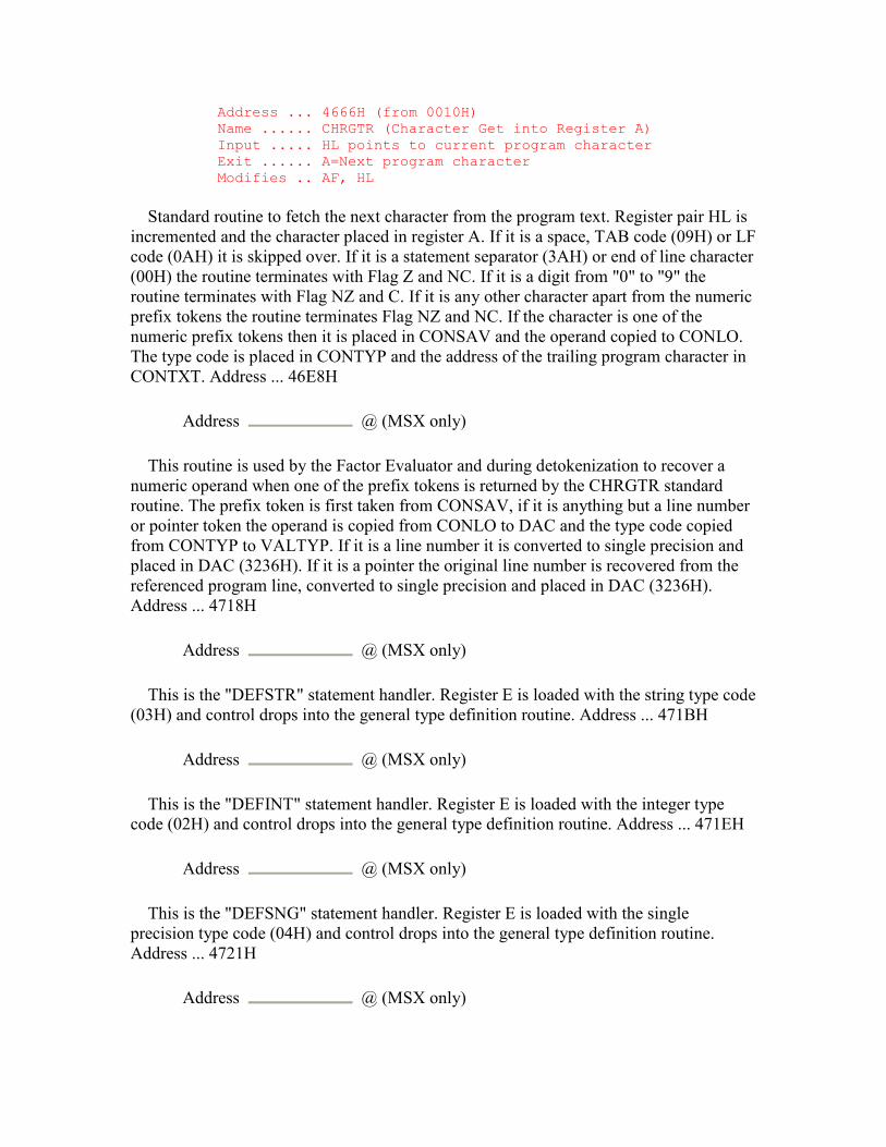
Address ... 4666H (from 0010H) Name ...... CHRGTR (Character Get into Register A) Input ..... HL points to current program character Exit ...... A=Next program character Modifies .. AF, HL
Standard routine to fetch the next character from the program text. Register pair HL is incremented and the character placed in register A. If it is a space, TAB code (09H) or LF code (0AH) it is skipped over. If it is a statement separator (3AH) or end of line character (00H) the routine terminates with Flag Z and NC. If it is a digit from "0" to "9" the routine terminates with Flag NZ and C. If it is any other character apart from the numeric prefix tokens the routine terminates Flag NZ and NC. If the character is one of the numeric prefix tokens then it is placed in CONSAV and the operand copied to CONLO. The type code is placed in CONTYP and the address of the trailing program character in CONTXT. Address ... 46E8H
Address @ (MSX only)
This routine is used by the Factor Evaluator and during detokenization to recover a numeric operand when one of the prefix tokens is returned by the CHRGTR standard routine. The prefix token is first taken from CONSAV, if it is anything but a line number or pointer token the operand is copied from CONLO to DAC and the type code copied from CONTYP to VALTYP. If it is a line number it is converted to single precision and placed in DAC (3236H). If it is a pointer the original line number is recovered from the referenced program line, converted to single precision and placed in DAC (3236H). Address ... 4718H
Address @ (MSX only)
This is the "DEFSTR" statement handler. Register E is loaded with the string type code (03H) and control drops into the general type definition routine. Address ... 471BH
Address @ (MSX only)
This is the "DEFINT" statement handler. Register E is loaded with the integer type code (02H) and control drops into the general type definition routine. Address ... 471EH
Address @ (MSX only)
This is the "DEFSNG" statement handler. Register E is loaded with the single precision type code (04H) and control drops into the general type definition routine. Address ... 4721H
Address @ (MSX only)

This is the "DEFDBL" statement handler. Register E is loaded with the double precision type code (08H) and the first range definition character checked (64A7H). If this is not upper case alphabetic a "Syntax error" is generated (4055H). If a "-" token (F2H) follows the second range definition character is taken and checked (64A7H), the difference between the two determines the number of entries in DEFTBL that are filled with the type code. Address ... 4755H
Address @ (MSX only)
This routine evaluates an operand and converts it to an integer in register pair DE (520FH). If the operand is negative an "Illegal function call" error is generated. - 121 - 5. ROM BASIC INTERPRETER Address ... 475FH
Address @ (MSX only)
This routine is used by the statement handlers shown in the table at 43B5H to collect a single line number operand from the program text and convert it to an unsigned integer in register pair DE. If the first character in the text is a "." (2EH) the routine terminates with the contents of DOT. If it is one of the line number tokens (0DH or 0EH) the routine terminates with the contents of CONLO. Otherwise successive digits are taken and added to the product, with appropriate multiplications by ten, until a non-numeric character is found. Address ... 479EH
Address @ (MSX only)
This is the "RUN" statement handler. If no line number operand is present in the program text the system is cleared (629AH) and control returns to the Runloop with register pair HL pointing to the start of the Program Storage Area. If a line number operand is present the system is cleared (62A1H) and control transfers to the "GOTO" statement handler (47E7H). Otherwise a following filename is assumed, for example RUN "CAS:FILE", and control transfers to the "LOAD" statement handler (6B5BH). Address ... 47B2H
Address @ (MSX only)
This is the "GOSUB" statement handler. After checking that stack space is available (625EH) the line number operand is collected and placed in register pair DE (4769H). The seven byte parameter block is then pushed onto the stack and control transfers to the "GOTO" handler (47EBH). The parameter block is made up of the following:
2 bytes ... End of statement address 2 bytes ... Current line number 2 bytes ... 0000H 1 byte ... GOSUB token (8DH)

The parameter block remains on the stack until a "RETURN" statement is executed. It is then used to determine the original program text position after which it is discarded. Address ... 47CFH
Address @ (MSX only)
This routine is used by the Runloop interrupt processor (6389H) to create a "GOSUB" type parameter block on the Z80 stack. An interrupt block is identical to a normal block except that the two zero bytes shown above are replaced by the address of the device's entry in TRPTBL. This address will be used by the "RETURN" statement handler to update the device's interrupt status once a subroutine has terminated. After pushing the parameter block control transfers to the Runloop to execute the program line whose address is supplied in register pair DE. - 122 - 5. ROM BASIC INTERPRETER Address ... 47E8H
Address @ (MSX only)
This is the "GOTO" statement handler. The line number operand is collected (4769H) and placed in register pair HL. If it is a pointer control transfers immediately to the Runloop to begin execution at the new program text position. Otherwise the line number is compared with the current line number to determine the starting position for the program text search. If it is greater the search starts from the end of this line (4298H), if it is smaller it starts from the beginning of the Program Text Area (4295H). If the referenced line cannot be found an "Undefined line number" error is generated (481CH). Otherwise the line number operand is replaced by the referenced program line's address and its token changed to the pointer type (5583H). Control then transfers to the Runloop to execute the referenced program line. Address ... 481CH
Address @ (MSX only)
This is the "Undefined line number" error generator. Address ... 4821H
Address @ (MSX only)
This is the "RETURN" statement handler. A dummy loop Variable address is placed in register pair DE and the Z80 stack searched (3FE2H) to find the first parameter block not belonging to a "FOR" loop, this section of stack is then discarded. If no "GOSUB" token (8DH) is found at this point a "RETURN without GOSUB" error is generated.
The next two bytes are then taken from the block, if they are non-zero the block was generated by an interrupt and the temporary "STOP" condition is removed (633EH). The program text is then examined, if anything follows the "RETURN" token itself it is assumed to be a line number operand and control transfers to the "GOTO" handler (47E8H). Otherwise the old line number and program text address are taken from the block and control returns to the Runloop. Address ... 485BH

Address @ (MSX only)
This is the "DATA" statement handler. The program text is skipped over until a statement separator (3AH) or end of line character (00H) is found. This routine is also the "REM" and "ELSE" statement handler via the entry point at 485DH, in this case only the end of line character acts as a terminator. Address ... 4880H
Address @ (MSX only)
This is the "LET" statement handler. The Variable is first located (PTRGET, 5EA4H), its address saved in TEMP and the operand evaluated (FRMEVL, 4C64H). If necessary the operand's type is then changed to match that of the Variable (517AH). Assuming the operand is one of the three numeric types it is simply copied - 123 - 5. ROM BASIC INTERPRETER from DAC to the Variable in the Variable Storage Area (2EF3H). If the operand is a string type the address of the string body is taken from the descriptor and checked. If it is in KBUF, as would be the case for an explicit string in a direct statement, the body is first copied to the String Storage Area and a new descriptor created (6611H). The descriptor is then freed from TEMPST (67EEH) and copied to the Variable in the Variable Storage Area (2EF3H). Address ... 48E4H
Address @ (MSX only)
This is the "ON ERROR", "ON DEVICE GOSUB" and "ON EXPRESSION" statement handler. If the next program text character is not an "ERROR" token (A6H) control transfers to the "ON DEVICE GOSUB" and "ON EXPRESSION" handler (490DH). The program text is checked to ensure that a "GOTO" token (89H) follows and then the line number operand collected (4769H). The program text is searched to obtain the address of the referenced line (4293H) and this is placed in ONELIN. If the line number operand is non-zero the routine then terminates. If the line number operand is zero ONEFLG is checked to see if an error situation already exists (implying that the statement is inside a BASIC error recovery routine). If so control transfers to the error handler (4096H) to force an immediate error, otherwise the routine terminates normally. Address ... 490DH
Address @ (MSX only)
This is the "ON DEVICE GOSUB" and "ON EXPRESSION" statement handler. If the next program text character is not a device token (7810H) control transfers to the "ON EXPRESSION" handler (4943H). After checking the program text for a "GOSUB" token (8DH) each of the line number operands required for a particular device is collected in turn (4769H). Assuming a given line number operand is non-zero the program text is searched to find the address of the referenced line (4293H) and this is placed in the device's entry in TRPTBL (785CH). The routine terminates when no more line number operands are found. Address ... 4943H

Address @ (MSX only)
This is the "ON EXPRESSION" statement handler. The operand is evaluated (GETBYT, 521CH) and the following "GOSUB" token (8DH) or "GOTO" token (89H) placed in register A. The operand is then used to count along the program text until register pair HL points to the required line number operand. Control then transfers back to the Runloop execution point (4646H) to decode the "GOSUB" or "GOTO" token. Address ... 495DH
Address @ (MSX only)
This is the "RESUME" statement handler. ONEFLG is first checked to make sure that an error condition already exists, if not a "RESUME without error" is generated (4064H). If a non-zero line number operand follows control transfers to the "GOTO" handler (47EBH). If a "NEXT" token (83H) follows the position of the error is restored from ERRTXT and ERRLIN, the start of the next statement is found (485BH) and the routine terminates. If there is no line number operand or if it is zero the position of the error is found from ERRTXT and ERRLIN and the routine terminates. Address ... 49AAH
Address @ (MSX only)
This is the "ERROR" statement handler. The operand is evaluated and placed in register E (GETBYT, 521CH). If it is zero an "Illegal function call" error is generated (475AH), otherwise control transfers to the error handler (406FH). Address ... 49B5H
Address @ (MSX only)
This is the "AUTO" Statement handler. The optional start and increment line number operands, both with a default value of ten, are collected (475FH) and placed in AUTLIN and AUTINC. After making AUTFLG non-zero the Runloop return is destroyed and control transfers directly to the Mainloop (4134H). Address ... 49E5H
Address @ (MSX only)
This is the "IF" statement handler. The operand is evaluated (FRMEVL, 4C64H) and, after checking for a "GOTO" token (89H) or "THEN" token (DAH), its sign is tested (2EA1H). If the operand is non-zero (true) the following text is executed either by an immediate transfer to the Runloop (4646H) or, for a line number operand, the "GOTO" handler (47E8H). If the operand is zero (false) the statement text is scanned (485BH) until an "ELSE" token (A1H) is found not balanced by an "IF" token (8BH) and execution re-commences. Address ... 4A1DH
Address @ (MSX only)

This is the "LPRINT" statement handler. PRTFLG is set to 01H, to direct output to the printer, and control transfers to the "PRINT" handler (4A29H). Address ... 4A24H
Address @ (MSX only)
This is the "PRINT" statement handler. The program text is first checked for a trailing buffer number and, if necessary, PTRFIL set to direct output to the required I/O buffer (6D57H). If no more program text exists a CR,LF is issued (7328H) and the routine terminates (4AFFH). Otherwise successive characters are taken from the program text and analyzed. If a "USING" token (E4H) is found control transfers to the "PRINT USING" handler (60B1H). If a ";" character is found control just transfers back to the start to fetch the next item (4A2EH). If a comma is found sufficient spaces are issued to bring the current print position, from TTYPOS, LPTPOS or an I/O buffer FCB, to an integral multiple of fourteen. If output is directed to the screen and the print position is equal to or greater than the contents of CLMLST or if output is directed to the printer and it is equal to or greater than 238 then a CR,LF is issued instead (7328H). If a "SPC(" token (DFH) is found the operand is evaluated (521BH) and the required number of spaces are output. If a "TAB(" token (DBH) is found the operand is evaluated (521BH) and sufficient spaces issued to bring the current print position, from TTYPOS, LPTPOS or an I/O buffer FCB, to the required point.
If none of these characters is found the program text contains a data item which is then evaluated (FRMEVL, 4C64H). If the operand is a string it is simply displayed (667BH). If it is numeric it is first converted to text in FBUFFR (3425H) and a string descriptor created (6635H). If output is directed to an I/O buffer the resulting string is then displayed (667BH). If output is directed to the screen or printer the current print position, from TTYPOS or LPTPOS, is compared with the line length and a CR,LF issued (7328H) if the output will not fit on the line. The maximum line length is 255 for the printer and is taken from LINLEN for the screen. Once the string has been displayed control transfers back to the start of the handler. Address ... 4AFFH
Address @ (MSX only)
This routine zeroes PRTFLG and PTRFIL to return the Interpreter's output to the screen. Address ... 4B0EH
Address @ (MSX only)
This is the "LINE INPUT", "LINE INPUT#" and "LINE" statement handler. If the following program text character is anything other than an "INPUT" token (85H) control transfers to the "LINE" statement handler (58A7H). If the following program text character is a "#" (23H) control transfers to the "LINE INPUT#" statement handler (6D8FH).
Any following prompt string is evaluated and displayed (4B7BH) and the Variable located (PTRGET, 5EA4H) and checked to ensure that it is a string type (3058H). The line of text is collected from the console via the INLIN standard routine, if Flag C (CTRL-STOP) is returned control transfers to the "STOP" statement handler (63FEH). Otherwise the input string is analyzed and a descriptor created (6638H), control then transfers to the "LET" statement handler for assignment (4892H). It should be noted that the screen is not forced to text mode before the input is collected. Address ... 4B3AH
Address @ (MSX only)
This is the plain text message "?Redo from start", CR, LF terminated by a zero byte. - 126 - 5. ROM BASIC INTERPRETER Address ... 4B4DH
Address @ (MSX only)
This routine is used by the "READ/INPUT" statement handler if it has failed to convert a data item to numeric form. If in "READ" mode (FLGINP is non-zero) a "Syntax error" is generated (404FH). Otherwise the message "?Redo from start" is displayed (6678H) and control returns to the statement handler. Address ... 4B62H
Address @ (MSX only)
This is the "INPUT#" Statement handler. The buffer number is evaluated and PTRFIL set to direct input from the required I/O buffer (6D55H), control then transfers to the combined "READ/INPUT" statement handler (4B9BH). Address ... 4B6CH
Address @ (MSX only)
This is the "INPUT" statement handler. If the next program text character is a "#" control transfers to the "INPUT#" statement handler (4B62H). Otherwise the screen is forced to text mode, via the TOTXT standard routine, and any prompt string analyzed (6636H) and displayed (667BH). A question mark is then displayed and a line of text collected from the console via the QINLIN standard routine. If this returns Flag C (CTRL- STOP) control transfers to the "STOP" handler (63FEH). If the first character in BUF is zero (null input) the handler terminates by skipping to the end of the statement (485AH), otherwise control drops into the combined "READ/INPUT" handler. Address ... 4B9FH
Address @ (MSX only)
This is the "READ" statement handler, a large section is also used by the "INPUT" and "INPUT#" statements so the structure is rather awkward. Each Variable found in the program text is located in turn (PTRGET, 5EA4H), for each one the corresponding data item is obtained and assigned to the Variable by the "LET" handler (4893H). When in
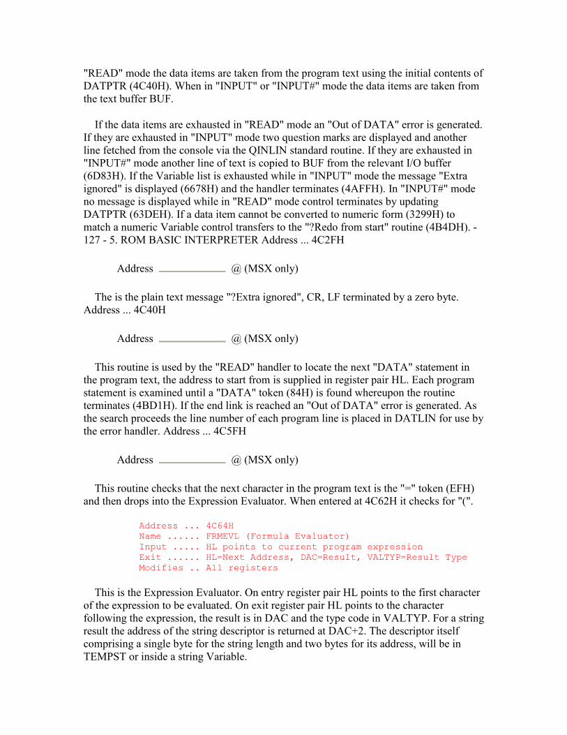
"READ" mode the data items are taken from the program text using the initial contents of DATPTR (4C40H). When in "INPUT" or "INPUT#" mode the data items are taken from the text buffer BUF.
If the data items are exhausted in "READ" mode an "Out of DATA" error is generated. If they are exhausted in "INPUT" mode two question marks are displayed and another line fetched from the console via the QINLIN standard routine. If they are exhausted in "INPUT#" mode another line of text is copied to BUF from the relevant I/O buffer (6D83H). If the Variable list is exhausted while in "INPUT" mode the message "Extra ignored" is displayed (6678H) and the handler terminates (4AFFH). In "INPUT#" mode no message is displayed while in "READ" mode control terminates by updating DATPTR (63DEH). If a data item cannot be converted to numeric form (3299H) to match a numeric Variable control transfers to the "?Redo from start" routine (4B4DH). - 127 - 5. ROM BASIC INTERPRETER Address ... 4C2FH
Address @ (MSX only)
The is the plain text message "?Extra ignored", CR, LF terminated by a zero byte. Address ... 4C40H
Address @ (MSX only)
This routine is used by the "READ" handler to locate the next "DATA" statement in the program text, the address to start from is supplied in register pair HL. Each program statement is examined until a "DATA" token (84H) is found whereupon the routine terminates (4BD1H). If the end link is reached an "Out of DATA" error is generated. As the search proceeds the line number of each program line is placed in DATLIN for use by the error handler. Address ... 4C5FH
Address @ (MSX only)
This routine checks that the next character in the program text is the "=" token (EFH) and then drops into the Expression Evaluator. When entered at 4C62H it checks for "(".
Address ... 4C64H Name ...... FRMEVL (Formula Evaluator) Input ..... HL points to current program expression Exit ...... HL=Next Address, DAC=Result, VALTYP=Result Type Modifies .. All registers
This is the Expression Evaluator. On entry register pair HL points to the first character of the expression to be evaluated. On exit register pair HL points to the character following the expression, the result is in DAC and the type code in VALTYP. For a string result the address of the string descriptor is returned at DAC+2. The descriptor itself comprising a single byte for the string length and two bytes for its address, will be in TEMPST or inside a string Variable.

An expression is a list of factors (4DC7H) linked together by operators with differing precedence levels. To process such an expression correctly the Expression Evaluator must be able to temporarily stack an intermediate result, if the next operator has a higher precedence than the current operator, and start afresh on a new calculation. It therefore has two basic operations, STACK and APPLY. For example:
3+250\2^2*3^3+1, STACK: 3+ (\ follows) STACK: 250\ ( follows) APPLY: 2^2=4 (* follows) STACK: 4* ( follows) APPLY: 3^3=27 (+ follows) APPLY: 4*27=108 (+ follows) APPLY: 250\108=2 (+ follows) APPLY: 3+2=5 (+ follows) APPLY: 5+1=6 (, follows)
- 128 - 5. ROM BASIC INTERPRETER
Evaluation terminates when the next operator has a precedence equal to or lower than the initial precedence and the stack is empty. The expression delimiter, shown as a comma in the example, is regarded as having a precedence of zero and so will always halt evaluation. Normally the Expression Evaluator starts off with an initial precedence of zero but the entry point at 4C67H may be used to supply an alternative value in register D. This facility is used by the Factor Evaluator to restrict the range of evaluation when applying the monadic negation and "NOT" operators. Address ... 4D22H
Address @ (MSX only)
This routine is used by the Expression Evaluator to apply an infix math operator (+-*/ ) to a pair of numeric operands. There are separate routines for the relational operators (4F57H) and the logical operators (4F78H). The first operand, its type code, and the operator token are supplied on the Z80 stack, the second operand and its type code are supplied in DAC and VALTYP. The types of both operands are first compared, if they differ the lowest precision operand is converted to match the higher. The operands are then moved to the positions required by the math routines. For integers the first operand is placed in register pair DE and the second in register pair HL. For single precision the first operand is placed in registers C, B, E, D and the second in DAC. For double precision the first operand is placed in DAC and the second in ARG. The operator token is then used to obtain the required address from the table at 3D51H, 3D5DH or 3D69H, depending upon the operand type, and control transfers to the relevant math routine. Address ... 4DB8H
Address @ (MSX only)
This routine is used by the Expression Evaluator to divide two integer operands. The first operand is contained in register pair DE and the second in register pair HL, the result
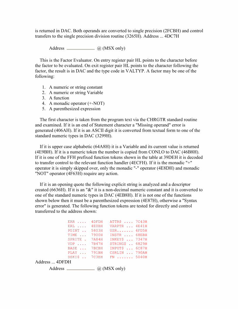
is returned in DAC. Both operands are converted to single precision (2FCBH) and control transfers to the single precision division routine (3265H). Address ... 4DC7H
Address @ (MSX only)
This is the Factor Evaluator. On entry register pair HL points to the character before the factor to be evaluated. On exit register pair HL points to the character following the factor, the result is in DAC and the type code in VALTYP. A factor may be one of the following:
1. A numeric or string constant 2. A numeric or string Variable 3. A function 4. A monadic operator (+-NOT) 5. A parenthesized expression
The first character is taken from the program text via the CHRGTR standard routine and examined. If it is an end of Statement character a "Missing operand" error is generated (406AH). If it is an ASCII digit it is converted from textual form to one of the standard numeric types in DAC (3299H).
If it is upper case alphabetic (64A8H) it is a Variable and its current value is returned (4E9BH). If it is a numeric token the number is copied from CONLO to DAC (46B8H). If it is one of the FFH prefixed function tokens shown in the table at 39DEH it is decoded to transfer control to the relevant function handler (4ECFH). If it is the monadic "+" operator it is simply skipped over, only the monadic "-" operator (4E8DH) and monadic "NOT" operator (4F63H) require any action.
If it is an opening quote the following explicit string is analyzed and a descriptor created (6636H). If it is an "&" it is a non-decimal numeric constant and it is converted to one of the standard numeric types in DAC (4EB8H). If it is not one of the functions shown below then it must be a parenthesized expression (4E87H), otherwise a "Syntax error" is generated. The following function tokens are tested for directly and control transferred to the address shown:
ERR .... 4DFDH ATTR$ .... 7C43H ERL .... 4E0BH VARPTR ... 4E41H POINT .. 5803H USR....... 4FD5H TIME ... 7900H INSTR .... 68EBH SPRITE . 7A84H INKEY$ ... 7347H VDP .... 7B47H STRING$ .. 6829H BASE ... 7BCBH INPUT$ ... 6C87H PLAY ... 791BH CSRLIN ... 790AH DSKI$ .. 7C3EH FN ....... 5040H
Address ... 4DFDH Address @ (MSX only)

This routine is used by the Factor Evaluator to apply the "ERR" function. The contents of ERRFLG are placed in DAC as an integer (4FCFH). Address ... 4E0BH
Address @ (MSX only)
This routine is used by the Factor Evaluator to apply the "ERL" function. The contents of ERRLIN are copied to DAC as a single precision number (3236H). Address ... 4E41H
Address @ (MSX only)
This routine is used by the Factor Evaluator to apply the "VARPTR" function. If the function token is followed by a "#" the buffer number is evaluated (521BH), the I/O buffer FCB located (6A6DH) and its address placed in DAC as an integer (2F99H). Otherwise the Variable is located (5F5DH) and its address placed in DAC as an integer (2F99H). - 130 - 5. ROM BASIC INTERPRETER Address ... 4E8DH
Address @ (MSX only)
This routine is used by the Factor Evaluator to apply the monadic "-" operator. Register D is set to a precedence value of 7DH, the factor evaluated (4C67H) and then negated (2E86H). Address ... 4E9BH
Address @ (MSX only)
This routine is used by the Factor Evaluator to return the current value of a Variable. The Variable is first located (PTRGET, 5EA4H). If it is a string Variable its address is placed in DAC to point to the descriptor. Otherwise the contents of the Variable are copied to DAC (2F08). Address ... 4EA9H
Address @ (MSX only)
This routine returns the single character pointed to by register pair HL in register A, if it is a lower case alphabetic it converts it to upper case. Address ... 4EB8H
Address @ (MSX only)
This routine is used by the Factor Evaluator and the numeric input routine (3299H) to convert an ampersand ("&") Prefixed number from textual form to an integer in DAC. As each legal character is found the product is multiplied by 2, 8 or 16, depending upon the character which initially followed the ampersand, and the new digit added to it. If the product overflows an "Overflow" error is generated (4067H). The routine terminates when an unacceptable character is found. Address ... 4EFCH
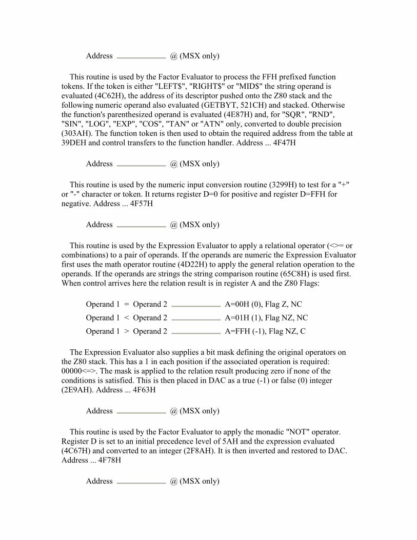
Address @ (MSX only)
This routine is used by the Factor Evaluator to process the FFH prefixed function tokens. If the token is either "LEFT$", "RIGHT$" or "MID$" the string operand is evaluated (4C62H), the address of its descriptor pushed onto the Z80 stack and the following numeric operand also evaluated (GETBYT, 521CH) and stacked. Otherwise the function's parenthesized operand is evaluated (4E87H) and, for "SQR", "RND", "SIN", "LOG", "EXP", "COS", "TAN" or "ATN" only, converted to double precision (303AH). The function token is then used to obtain the required address from the table at 39DEH and control transfers to the function handler. Address ... 4F47H
Address @ (MSX only)
This routine is used by the numeric input conversion routine (3299H) to test for a "+" or "-" character or token. It returns register D=0 for positive and register D=FFH for negative. Address ... 4F57H
Address @ (MSX only)
This routine is used by the Expression Evaluator to apply a relational operator (<>= or combinations) to a pair of operands. If the operands are numeric the Expression Evaluator first uses the math operator routine (4D22H) to apply the general relation operation to the operands. If the operands are strings the string comparison routine (65C8H) is used first. When control arrives here the relation result is in register A and the Z80 Flags:
Operand 1 = Operand 2 A=00H (0), Flag Z, NC
Operand 1 < Operand 2 A=01H (1), Flag NZ, NC
Operand 1 > Operand 2 A=FFH (-1), Flag NZ, C
The Expression Evaluator also supplies a bit mask defining the original operators on the Z80 stack. This has a 1 in each position if the associated operation is required: 00000<=>. The mask is applied to the relation result producing zero if none of the conditions is satisfied. This is then placed in DAC as a true (-1) or false (0) integer (2E9AH). Address ... 4F63H
Address @ (MSX only)
This routine is used by the Factor Evaluator to apply the monadic "NOT" operator. Register D is set to an initial precedence level of 5AH and the expression evaluated (4C67H) and converted to an integer (2F8AH). It is then inverted and restored to DAC. Address ... 4F78H
Address @ (MSX only)
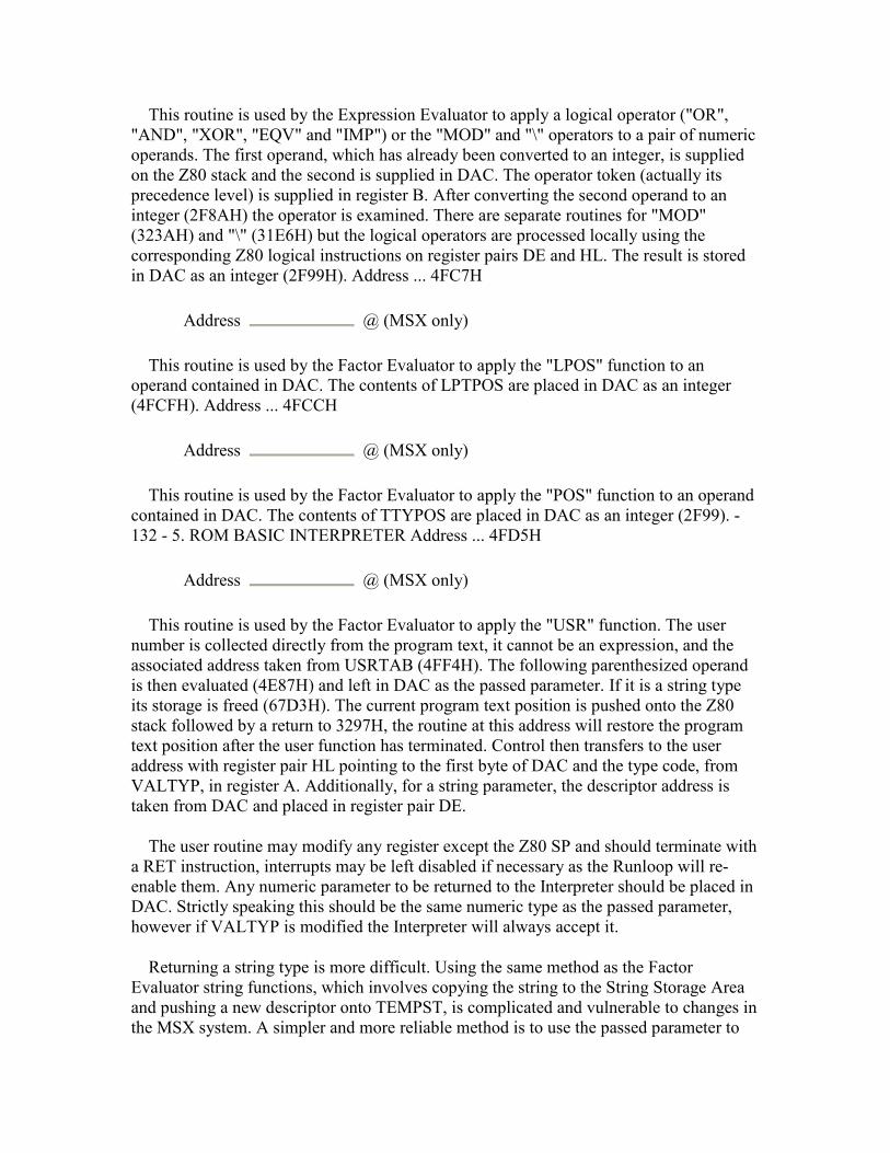
This routine is used by the Expression Evaluator to apply a logical operator ("OR", "AND", "XOR", "EQV" and "IMP") or the "MOD" and "\" operators to a pair of numeric operands. The first operand, which has already been converted to an integer, is supplied on the Z80 stack and the second is supplied in DAC. The operator token (actually its precedence level) is supplied in register B. After converting the second operand to an integer (2F8AH) the operator is examined. There are separate routines for "MOD" (323AH) and "\" (31E6H) but the logical operators are processed locally using the corresponding Z80 logical instructions on register pairs DE and HL. The result is stored in DAC as an integer (2F99H). Address ... 4FC7H
Address @ (MSX only)
This routine is used by the Factor Evaluator to apply the "LPOS" function to an operand contained in DAC. The contents of LPTPOS are placed in DAC as an integer (4FCFH). Address ... 4FCCH
Address @ (MSX only)
This routine is used by the Factor Evaluator to apply the "POS" function to an operand contained in DAC. The contents of TTYPOS are placed in DAC as an integer (2F99). - 132 - 5. ROM BASIC INTERPRETER Address ... 4FD5H
Address @ (MSX only)
This routine is used by the Factor Evaluator to apply the "USR" function. The user number is collected directly from the program text, it cannot be an expression, and the associated address taken from USRTAB (4FF4H). The following parenthesized operand is then evaluated (4E87H) and left in DAC as the passed parameter. If it is a string type its storage is freed (67D3H). The current program text position is pushed onto the Z80 stack followed by a return to 3297H, the routine at this address will restore the program text position after the user function has terminated. Control then transfers to the user address with register pair HL pointing to the first byte of DAC and the type code, from VALTYP, in register A. Additionally, for a string parameter, the descriptor address is taken from DAC and placed in register pair DE.
The user routine may modify any register except the Z80 SP and should terminate with a RET instruction, interrupts may be left disabled if necessary as the Runloop will re-enable them. Any numeric parameter to be returned to the Interpreter should be placed in DAC. Strictly speaking this should be the same numeric type as the passed parameter, however if VALTYP is modified the Interpreter will always accept it.
Returning a string type is more difficult. Using the same method as the Factor Evaluator string functions, which involves copying the string to the String Storage Area and pushing a new descriptor onto TEMPST, is complicated and vulnerable to changes in the MSX system. A simpler and more reliable method is to use the passed parameter to
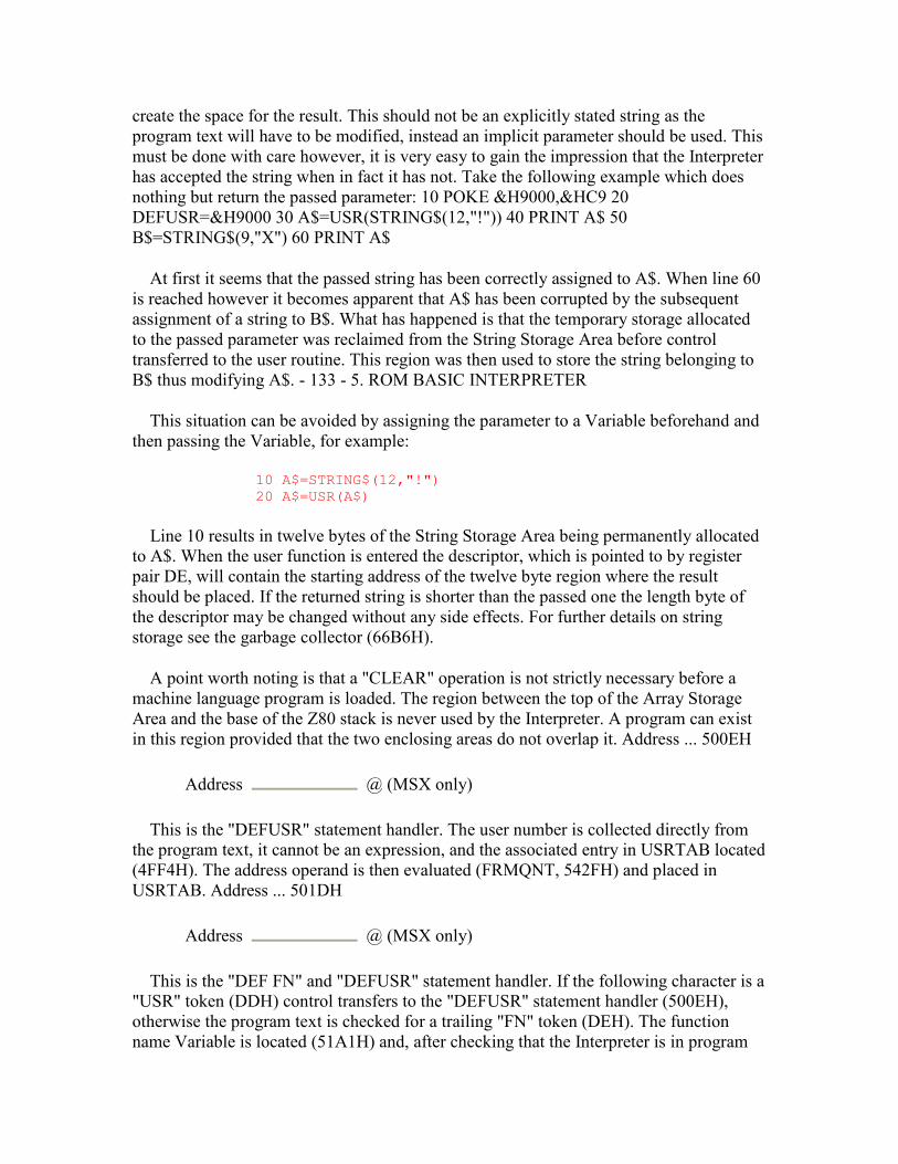
create the space for the result. This should not be an explicitly stated string as the program text will have to be modified, instead an implicit parameter should be used. This must be done with care however, it is very easy to gain the impression that the Interpreter has accepted the string when in fact it has not. Take the following example which does nothing but return the passed parameter: 10 POKE &H9000,&HC9 20 DEFUSR=&H9000 30 A$=USR(STRING$(12,"!")) 40 PRINT A$ 50 B$=STRING$(9,"X") 60 PRINT A$
At first it seems that the passed string has been correctly assigned to A$. When line 60 is reached however it becomes apparent that A$ has been corrupted by the subsequent assignment of a string to B$. What has happened is that the temporary storage allocated to the passed parameter was reclaimed from the String Storage Area before control transferred to the user routine. This region was then used to store the string belonging to B$ thus modifying A$. - 133 - 5. ROM BASIC INTERPRETER
This situation can be avoided by assigning the parameter to a Variable beforehand and then passing the Variable, for example:
10 A$=STRING$(12,"!") 20 A$=USR(A$)
Line 10 results in twelve bytes of the String Storage Area being permanently allocated to A$. When the user function is entered the descriptor, which is pointed to by register pair DE, will contain the starting address of the twelve byte region where the result should be placed. If the returned string is shorter than the passed one the length byte of the descriptor may be changed without any side effects. For further details on string storage see the garbage collector (66B6H).
A point worth noting is that a "CLEAR" operation is not strictly necessary before a machine language program is loaded. The region between the top of the Array Storage Area and the base of the Z80 stack is never used by the Interpreter. A program can exist in this region provided that the two enclosing areas do not overlap it. Address ... 500EH
Address @ (MSX only)
This is the "DEFUSR" statement handler. The user number is collected directly from the program text, it cannot be an expression, and the associated entry in USRTAB located (4FF4H). The address operand is then evaluated (FRMQNT, 542FH) and placed in USRTAB. Address ... 501DH
Address @ (MSX only)
This is the "DEF FN" and "DEFUSR" statement handler. If the following character is a "USR" token (DDH) control transfers to the "DEFUSR" statement handler (500EH), otherwise the program text is checked for a trailing "FN" token (DEH). The function name Variable is located (51A1H) and, after checking that the Interpreter is in program
mode (5193H), the current program text position is placed there. Each of the Variables in the formal parameter list is then located in succession (PTRGET, 5EA4H), this is simply to ensure that they are created. The routine terminates by skipping over the remainder of the statement (485BH) as the function body is not required at this time. Address ... 5040H
Address @ (MSX only)
This routine is used by the Factor Evaluator to apply the "FN" function. The function name Variable is first located (51A1H) to obtain the address of the function definition in the program text. Each formal Variable from the function definition is located in turn (PTRGET, 5EA4H) and its address pushed onto the Z80 stack. As each one is found the corresponding actual parameter is evaluated (4C64H) and pushed onto the stack with it. If necessary the type of the actual parameter is converted to match that of the formal parameter (517AH).
When both lists are exhausted each formal Variable address and actual parameter are popped from the stack in turn. Each Variable is then copied from the Variable Storage Area to PARM2 with its value replaced by the actual parameter. It should be noted that, because PARM2 is only a hundred bytes long, a maximum of nine double precision parameters is allowed. When all the actual parameters have been copied to PARM2 the entire contents of PARM1 (the current parameter area) are pushed onto the Z80 stack and PARM2 is copied to PARM1 (518EH). Register pair HL is then set to the start of the function body in the program text and the expression is evaluated (4C5FH). The old contents of PARM1 are popped from the stack and restored. Finally the result of the evaluation is type converted if necessary to match the function name type (517AH).
A user defined function differs from a normal expression in only one respect, it has its own set of local Variables. These Variables are created in PARM1 when the function is invoked and disappear when it terminates. When a normal Variable search is initiated by the Expression Evaluator the region examined is the Variable Storage Area. However, if NOFUNS is non-zero, indicating at least one active user function, PARM1 will be searched instead, only if this fails will the search move on to the global Variables in the Variable Storage Area. Using a local Variable area specific to each invocation of a function means that the same Variable names can be used throughout without the Variables overwriting each other or the global Variables.
It is worth noting that a user defined function is slower than an inline expression or even a subroutine. The search carried out to find the function name Variable, plus the large amount of stacking and destacking, are significant overheads. Address ... 5189H
Address @ (MSX only)
This routine moves a block of memory from the address pointed to by register pair DE to that pointed to by register pair HL, register pair BC defines the length. Address ... 5193H
Address @ (MSX only)
This routine generate an "Illegal direct" error if CURLIN shows the Interpreter to be in direct mode. Address ... 51A1H
Address @ (MSX only)
This routine checks the program text for an "FN" token (DEH) and then creates the function name Variable (5EA9H). These are distinguished from ordinary Variables by having bit 7 set in the first character of the Variable's name. - 135 - 5. ROM BASIC INTERPRETER Address ... 51ADH
Address @ (MSX only)
Control transfers to this routine from the Runloop execution point (4640H) if a token greater than D8H is found at the start of a statement. If the token is not an FFH prefixed function token a "Syntax error" is generated (4055H). If the function token is one of those which double as statements control transfers to the relevant handler, otherwise a "Syntax error" is generated. The statements in question are "MID$" (696EH), "STRIG" (77BFH) and "INTERVAL" (77B1H). There is actually no separate token for "INTERVAL", the "INT" token (85H) suffices with the remaining characters being checked by the statement handler. Address ... 51C9H
Address @ (MSX only)
This is the "WIDTH" statement handler. The operand is evaluated (GETBYT, 521CH) and its magnitude checked. If it is zero or greater than thirty-two or forty, depending upon the screen mode held in OLDSCR an "Illegal function call" error is generated (475AH). If it is the same as the current contents of LINLEN the routine terminates with no further action. Otherwise the current screen is cleared with a FORMFEED control code (0CH) via the OUTDO standard routine in case the screen is to be made smaller. The operand is then placed in LINLEN and either LINL32 or LINL40, depending upon the screen mode held in OLDSCR, and the screen cleared again in case it has been made larger. Because the line length variable to be changed is selected by OLDSCR, rather than SCRMOD, the width can still be changed even if the screen is currently in Graphics Mode or Multicolour Mode. In this case the change is effective when a return is made to the Interpreter Mainloop or an "INPUT" statement is executed. Address ... 520EH
Address @ (MSX only)
This routine evaluates the next expression in the program text (4C64H), converts it to an integer (2F8AH) and places the result in register pair DE. The magnitude and sign of the MSB are then tested and the routine terminates. Address ... 521BH
Address @ (MSX only)
This routine evaluates the next operand in the program text (4C64H) and converts it to an integer (5212H). If the operand is greater than 255 an "Illegal function call" error is generated (475AH).
Address ... 521CH Name ...... GETBYT (Get Byte Parameter) Input ..... HL points to current program expression Exit ...... HL=Next Address, A=E=Byte Read Modifies .. All registers
This routine evaluates the next operand in the program text to a byte datum. - 136 - 5. ROM BASIC INTERPRETER Address ... 5229H
Address @ (MSX only)
This is the "LLIST" statement handler. PRTFLG is set to 01H, to direct output to the printer, and control drops into the "LIST" statement handler. Address ... 522EH
Address @ (MSX only)
This is the "LIST" statement handler. The optional start and termination line number operands are collected and the starting position found in the program text (4279H). Successive program lines are listed until the end link is found, the CTRL-STOP key is pressed or the termination line number is reached, control then transfers directly to the Mainloop "OK" point (411FH). Each program line is listed by displaying its line number (3412H), detokenizing (5284H) and displaying (527BH) the line itself and then issuing a CR,LF (7328H). Address ... 5284H
Address @ (MSX only)
This routine is used by the "LIST" statement handler to convert a tokenized program line to textual form. On entry register pair HL points to the first character of the tokenized line. On exit the line of text is in BUF and is terminated by a zero byte.
Any normal or FFH prefixed token is converted to the corresponding keyword by a simple linear search of the tokens in the table at 3A72H. Exceptions are made if either an opening quote character, a "REM" token, or a "DATA" token has previously been found. Normally these tokens will be followed by plain text anyway, the check is made to stop graphics characters being interpreted as tokens. The three byte sequence ":" (3AH), "REM" token (8FH), " " token (E6H) is converted to the single " " character (27H) and the statement separator (3AH) preceding an "ELSE" token (A1H) is scrubbed out.

If one of the numeric tokens is found its value and type are first copied from CONLO and CONTYP to DAC and VALTYP (46E8H). It is then converted to textual form in FBUFFR by the decimal (3425H), octal (371EH) or hex (3722H) conversion routines. For octal and hex types the number is prefixed by an ampersand and an "O" or "H" letter. A type suffix, "'" or "#", is added to single precision or double precision numbers only if there is no decimal part and no exponent part ("E" or "D"). Address ... 53E2H
Address @ (MSX only)
This is the "DELETE" statement handler. The optional start and termination line number operands are collected and the starting position found in the program text (4279H). If any pointers exist in the program text they are converted back to line numbers (54EAH). The terminating program line is found by a search of the program text (4295H), if this address is smaller than that of the starting program line an "Illegal function call" error is generated (475AH), otherwise the message "OK" is displayed (6678H). The block of memory from the end of the terminating line to the start of the Variable Storage Area is copied down to the beginning of the starting line and VARTAB, ARYTAB and STREND are reset to the new (lower) end of the program text. Control then transfers directly to the end of the Mainloop (4237H) to reset the remaining pointers and to relink the Program Text Area. Note that, because control does not return to the normal "OK" point, the screen will not be returned to text mode. If the screen is in Graphics Mode or Multicolour mode when a "DELETE" is executed, which is admittedly rather unlikely, the system will crash. Address ... 541CH
Address @ (MSX only)
This routine is used by the Factor Evaluator to apply the "PEEK" function to an operand contained in DAC. The address operand is checked (5439H) then the byte read from memory and placed in DAC as an integer (4FCFH). Address ... 5423H
Address @ (MSX only)
This is the "POKE" statement handler. The address operand is evaluated (FRMQNT, 542FH) then the data operand evaluated (GETBYT, 521CH) and written to memory.
Address ... 542FH Name ...... FRMQNT (Formula Quantificator) Input ..... HL points to current program expression Exit ...... HL=Next Address, DE=Integer Datum Modifies .. All registers
This routine evaluates the next operand in the program text (4C64H) and places it in register pair DE as an integer (5439H). Address ... 5439H
Address @ (MSX only)

This routine converts the numeric operand contained in DAC into an integer in register pair HL. The operand must be in the range -32768 to +65535 and is normally an address as required by "POKE", "PEEK", "BLOAD", etc. The operand's type is first checked via the GETYPR standard routine, if it is already an integer it is simply placed in register pair HL (2F8AH). Assuming the operand is single precision or double precision its sign is checked, if it is negative it is converted to integer (2F8AH). Otherwise it is converted to single precision (2FB2H) and its magnitude checked (2F21H). If it is greater than 32767 and smaller than 65536 then -65536 is added (324EH) before it is converted to integer (2F8AH). Address ... 5468H
Address @ (MSX only)
This is the "RENUM" statement handler. If a new initial line number operand exists it is collected (475FH), otherwise a default value of ten of taken. If an old initial line number operand exists it is collected (475FH), otherwise a default value of zero is taken. If an increment line number operand exists it is collected (4769H), otherwise a default value of ten is taken.
The program text is then searched for existing line numbers equal to or greater than the new initial line number (4295H) and the old initial line number (4295H), an "Illegal function call" error is generated (475AH) if the new address is smaller than the old address. This is to catch any attempt to renumber high program lines down to existing low ones.
A dummy renumbering run of the program text is first carried out to check than no new line number will be generated with a value greater than 65529. This must be done as an error midway through the conversion would leave the program text in a confused state. Assuming all is well any line number operands in the program text are converted to pointers (54F6H). This neatly solves the problem of line number references, GOTO 50 for example, as the program text is not moved during renumbering. Starting at the old initial program text position each existing program line number is replaced with its new value. When the end link is reached any program text pointers are converted back to line number operands (54F1H) and control transfers directly to the Mainloop "OK" point (411EH). Address ... 54F6H
Address @ (MSX only)
When entered at 54F6H this routine converts every line number operand in the program text to a pointer. When entered at 54F7H it performs the reverse operation and converts every pointer in the program text back to a line number operand. Starting at the beginning of the Program Text Area each line is examined for a pointer token (0DH) or a line number operand token (0EH) depending upon the mode. In pointer to line number operand mode the pointer is replaced by the line number from the referenced program line and the token changed to 0EH. In line number operand to pointer mode the program text is searched (4295H) to find the relevant line, its address replaces the line number operand and the token is changed to 0DH. If the search is unsuccessful a message of the
form "Undefined line NNNN in NNNN" is displayed (6678H) and the conversion process continues. A special check is made for the "ON ERROR GOTO 0" statement, to prevent the generation of a spurious error message, but no check is made for the similar "RESUME 0" statement. In this case an error message will be displayed, this should be ignored. Address ... 555AH
Address @ (MSX only)
This is the plain text message "Undefined line " terminated by a zero byte.
Address ... 558CH (from 0008H) Name ...... SYNCHR (Syntax check Character) Input ..... HL points to character to check Exit ...... A=Next program character Modifies .. AF, HL
Standard routine to check the current program text character, whose address is supplied in register pair HL, against a reference character. The reference character is supplied as a single byte immediately following the CALL or RST instruction, for example:
RST 08H DEFB ","
If the characters do not match a "Syntax error" is generated (4055H), otherwise control transfers to the CHRGTR standard routine to fetch the next program character (4666H).
Address ... 5597H (from 0028H) Name ...... GETYPR (Get Type into Register A) Input ..... None Exit ...... AF=Type Modifies .. AF
Standard routine to return the type of the current operand, determined by VALTYP, as follows:
Integer ............ A=FFH, Flag M, NZ, C String ............. A=00H, Flag P, Z, C Single Precision ... A=01H, Flag P, NZ, C Double Precision ... A=05H, Flag P, NZ, NC
Address ... 55A8H Address @ (MSX only)
This is the "CALL" statement handler. The extended statement name, which is an unquoted string up to fifteen characters long terminated by a "(", ":" or end of line character (00H), is first copied from the program text to PROCNM, any unused bytes are zero filled. Bit 5 of each entry in SLTATR is then examined for an extension ROM with a statement handler. If a suitable ROM is found its position in SLTATR is converted to a Slot ID in register A and a ROM base address in register H (7E2AH). The statement

handler address is read from ROM locations four and five (7E1AH) and placed in register pair IX. The Slot ID is placed in the high byte of register pair IY and the ROM statement handler called via the CALSLT standard routine.
The ROM will examine the statement name and return Flag C if it does not recognize it, otherwise it performs the required operation. If the ROM call fails the search of SLTATR continues until the table is exhausted whereupon a "Syntax error" is generated (4055H). If the ROM call is successful the handler terminates. Address ... 55F8H
Address @ (MSX only)
This routine is used by the device name parser (6F15H) when it cannot recognize a device name found in the program text. Upon entry register pair HL points to the first character of the name and register B holds its length. The name is first copied to PROCNM and terminated by a zero byte. Bit 6 of each entry in SLTATR is then examined for an extension ROM with a device handler. If a suitable ROM is found its position in SLTATR is converted to a Slot ID in register A and a ROM base address in register H (7E2AH). The device handler address is read from ROM locations six and seven (7E1AH) and placed in register pair IX. The Slot ID is placed in the high byte of register pair IY, the unknown device code (FFH) in register A and the ROM device handler called via the CALSLT standard routine.
The ROM will examine the device name and return Flag C if it does not recognize it, otherwise it returns its own internal code from zero to three. If the ROM call fails the search of SLTATR continues until the table is exhausted whereupon a "Bad file name" error is generated (6E6BH). If the ROM call is successful the ROM's internal code is added to its SLTATR position, multiplied by a factor of four, to produce a global device code. The base code for each entry in SLTATR is shown below in hexadecimal. The "SS" and "PS" markers show the corresponding Secondary and Primary Slot numbers, each slot is composed of four pages:
SS0 SS1 SS2 SS3 +-------------+-------------+-------------+-------------+ | 00 04 08 0C | 10 14 18 1C | 20 24 28 2C | 30 34 38 3C | PS0 +-------------+-------------+-------------+-------------+ | 40 44 48 4C | 50 54 58 5C | 60 64 68 6C | 70 74 78 7C | PS1 +-------------+-------------+-------------+-------------+ | 80 84 88 8C | 90 94 98 9C | A0 A4 A8 AC | B0 B4 B8 BC | PS2 +-------------+-------------+-------------+-------------+ | C0 C4 C8 CC | D0 D4 D8 DC | E0 E4 E8 EC | F0 F4 F8 FC | PS3 +-------------+-------------+-------------+-------------+
Figure 44: Device Codes.
The global device code is used by the Interpreter until the time comes for the ROM to perform an actual device operation. It is then converted back into the ROM's Slot ID, base address and internal device code to perform the ROM access. Note that the codes from 0 to 8 are reserved for disk drive identifiers and those from FCH to FFH for the
standard devices GRP, CRT, LPT and CAS. With the current MSX hardware structure these codes correspond to physically improbable ROM configurations and are therefore safe to be used for specific purposes by the Interpreter. Address ... 564AH
Address @ (MSX only)
This routine is used by the function dispatcher (6F8FH) when it encounters a device code not belonging to one of the standard devices. The device code is first converted to a SLTATR position and then to a Slot ID in register A and ROM base address in register H (7E2DH). The ROM device handler address is read from ROM locations six and seven (7E1AH) and placed in register pair IX. The Slot ID is placed in the high byte of register pair IY, the ROM's internal device code in DEVICE and the ROM device handler called via the CALSLT standard routine. Address ... 566CH
Address @ (MSX only)
This entry point to the macro language parser is used by the "DRAW" statement handler, a later entry point (56A2H) is used by the "PLAY" statement handler. The command string is evaluated (4C64H) and its storage freed (FRESTR, 67D0H). After pushing a zero termination block onto the Z80 stack the length and address of the string body are placed in MCLLEN and MCLPTR and control drops into the parser mainloop. Address ... 56A2H
Address @ (MSX only)
This is the macro language parser mainloop, it is used to process the command string associated with a "DRAW" or "PLAY" statement. On entry the string length is in MCLLEN, the string address is in MCLPTR and the address of the relevant command table is in MCLTAB. The command tables contain the legal command letters, together with the associated command handler addresses, for each statement. The "DRAW" table is at 5D83H and the "PLAY" table at 752EH.
The parser mainloop first fetches the next character from the command string (56EEH). If there are no more characters left the next string descriptor is popped from the stack (568CH). If this is zero the parser terminates (5709H) if MCLFLG shows a "DRAW" statement to be active, otherwise control transfers back to the "PLAY" statement handler (7494H).
Assuming a command character exists the current command table is searched to check its legality, if no match is found an "Illegal function call" error is generated (475AH). The command table entry is then examined, if bit 7 is set the command takes an optional numeric parameter. If this is present it is collected and placed in register pair DE (571CH), otherwise a default value of one is taken. After pushing a return to the start of the parser mainloop onto the Z80 stack control transfers to the command handler at the address taken from the command table. Address ... 56EEH
Address @ (MSX only)
This routine is used by the macro language parser to fetch the next character from the command string. If MCLLEN is zero the routine terminates with Flag Z, there are no characters left. Otherwise the next character is taken from the address contained in MCLPTR and returned in register A, if the character is lower case it is converted to upper case. MCLPTR is then incremented and MCLLEN decrement Ed. - 142 - 5. ROM BASIC INTERPRETER Address ... 570BH
Address @ (MSX only)
This routine is used by the macro language parser to return an unwanted character to the command string. MCLLEN is incremented and MCLPTR decremented. Address ... 5719H
Address @ (MSX only)
This routine is used by the macro language parser to collect a numeric parameter from the command string. The result is a signed integer and is returned in register pair DE, it cannot be an expression. The first character is taken and examined, if it is a "+" it is ignored and the next character taken (5719H). If it is a "-" a return is set up to the negation routine (5795H) and the next character taken (5719H). If it is an "=" the value of the following Variable is returned (577AH). Otherwise successive characters are taken and a binary product accumulated until a non-numeric character is found. Address ... 575AH
Address @ (MSX only)
This routine is used by the macro language parser "=" and "X" handlers. The Variable name is copied to BUF until the ";" delimiter is found, if this takes more than thirty-nine characters to find an "Illegal function call" error is generated (475AH). Otherwise control transfers to the Factor Evaluator Variable handler (4E9BH) and the Variable contents are returned in DAC. Address ... 577AH
Address @ (MSX only)
This routine is used by the macro language parser to process the "=" character in a command parameter. The Variable's value is obtained (575AH), converted to an integer (2F8AH) and placed in register pair DE. Address ... 5782H
Address @ (MSX only)
This routine is used by the macro language parser to process the "X" command. The Variable is processed (575AH) and, after checking that stack space is available (625EH),

the current contents of MCLLEN and MCLPTR are stacked. Control then transfers to the parser entry point (5679H) to obtain the Variable's descriptor and process the new command string. Address ... 579CH
Address @ (MSX only)
This routine is used by various graphics statements to evaluate a coordinate pair in the program text. The coordinates must be parenthesized with a comma separating the component operands. If the coordinate pair is preceded by a "STEP" token (DCH) each component value is added to the corresponding component of the current graphics coordinates in GRPACX and GRPACY, otherwise the absolute values are returned. The X coordinate is returned in GRPACX, GXPOS and register pair BC. The Y coordinate is returned in GRPACY, GYPOS and register pair DE.
There are two entry points to the routine, the one which is used depends on whether the caller is expecting more than one coordinate pair. The "LINE" statement, for example, expects two coordinate pairs the first of which is the more flexible. The entry point at 579CH is used to collect the first coordinate pair and will accept the characters "-" or "@-" as representing the current graphics coordinates. The entry point at 57ABH is used for the second coordinate pair and requires an explicit operand. Address ... 57E5H
Address @ (MSX only)
This is the "PRESET" statement handler. The current background colour is taken from BAKCLR and control drops into the "PSET" handler. Address ... 57EAH
Address @ (MSX only)
This is the "PSET" statement handler. After the coordinate pair has been evaluated (57ABH) the current foreground colour is taken from FORCLR and used as the default when setting the ink colour (5850H). The current graphics coordinates are converted to a physical address, via the SCALXY and MAPXYC standard routines, and the colour of the current pixel set via the SETC standard routine. Address ... 5803H
Address @ (MSX only)
This routine is used by the Factor Evaluator to apply the "POINT" function. The current contents of CLOC, CMASK, GYPOS, GXPOS, GRPACY and GRPACX are stacked and the coordinate pair operand evaluated (57ABH). The colour of the new pixel is read via the SCALXY, MAPXYC and READC standard routines and placed in DAC as an integer (2F99H), the old coordinate values are then popped and restored. Note that a value of -1 is returned if the point coordinates are outside the screen. Address ... 5850H
Address @ (MSX only)
This graphics routine is used to evaluate an optional colour operand in the program text and to make it the current ink colour. After checking the screen mode (59BCH) the colour operand is evaluated (GETBYT, 521CH) and placed in ATRBYT. If no operand exists the colour code supplied in register A is placed in ATRBYT instead. Address ... 5871H
Address @ (MSX only)
This graphics routine returns the difference between the contents of GXPOS and register pair BC in register pair HL. If the result is negative (GXPOS<BC) it is negated to produce the absolute magnitude and Flag C is returned. Address ... 5883H
Address @ (MSX only)
This graphics routine returns the difference between the contents of GYPOS and register pair DE in register pair HL. If the result is negative (GYPOS<DE) it is negated to produce the absolute magnitude and Flag C is returned. Address ... 588EH
Address @ (MSX only)
This graphics routine swaps the contents of GYPOS and register pair DE. Address ... 5898H
Address @ (MSX only)
This graphics routine first swaps the contents of GYPOS and register pair DE (588EH) then swaps the contents of GXPOS and register pair BC. When entered at 589BH only the second operation is performed. Address ... 58A7H
Address @ (MSX only)
This is the "LINE" statement handler. The first coordinate pair (X1,Y1) is evaluated (579CH) and placed in register pairs BC,DE. After checking for the "-" token (F2H) the second coordinate pair (X2,Y2) is evaluated (57ABH) and left in GRPACX, GRPACY and GXPOS, GYPOS. After setting the ink colour (584DH) the program text is checked for a following "B" or "BF" option and either the box (5912H), boxfill (58BFH) or linedraw (58FCH) operation performed. None of these operations affects the current graphics coordinates in GRPACX and GRPACY, these are left at X2,Y2. Address ... 58BFH
Address @ (MSX only)
This routine performs the boxfill operation. Given that the supplied coordinate pairs define diagonally opposed points of the box two quantities must be derived from them.
The horizontal size of the box is obtained from the difference between X1 and X2, this gives the number of pixels to set per row. The vertical size is obtained from the difference between Y1 and Y2 giving the number of rows required. Starting at the physical address of X1,Y1, and moving successively lower via the DOWNC standard routine, the required number of pixel rows are filled in by repeated use of the NSETCX standard routine. Address ... 58FCH
Address @ (MSX only)
This routine performs the linedraw operation. After drawing the line (593CH) GXPOS and GYPOS are reset to X2,Y2 from GRPACX and GRPACY. - 145 - 5. ROM BASIC INTERPRETER Address ... 5912H
Address @ (MSX only)
This routine performs the box operation. The box is produced by drawing a line (58FCH) between each of the four corner points. The coordinates of each corner are derived from the initial operands by interchanging the relevant component of the pair. The drawing sequence is:
1. X1,Y2 to X2,Y2 2. X1,Y1 to X2,Y1 3. X2,Y1 to X2,Y2 4. X1,Y1 to X1,Y2
Address ... 593CH Address @ (MSX only)
This routine draws a line between the points X1,Y1, supplied in register pairs BC and DE and X2,Y2, supplied in GXPOS and GYPOS. The operation of the drawing mainloop (5993H) is best illustrated by an example, say LINE(0,0)-(10,4). To reach the end point of the line from its start ten horizontal steps (X2- X1) and four downward steps (Y2-Y1) must be taken altogether. The best approximation to a straight line therefore requires two and a half horizontal steps for every downward step (X2- X1/Y2-Y1). While this is impossible in practice, as only integral steps can be taken, the correct ratio can be achieved on average.
The method employed is to add the Y difference to a counter each time a rightward step is taken. When the counter exceeds the value of the X difference it is reset and one downward step is taken, this is in effect an integer division of the two difference values. Sometimes downward steps will be produced every two rightward steps and sometimes every three rightward steps. The average, however, will be one downward step every two and a half rightward steps. An equivalent BASIC program is shown below with a slightly offset BASIC line for comparison:
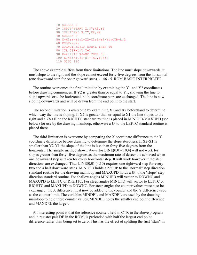
10 SCREEN 0 20 INPUT"START X,Y";X1,Y1 30 INPUT"END X,Y",X2,Y2 40 SCREEN 2 50 X=X1:Y=Y1:L=X2-X1:S=Y2-Y1:CTR=L/2 60 PSET(X,Y) 70 CTR=CTR+S:IF CTR<L THEN 90 80 CTR=CTR-L:Y=Y+1 90 X=X+1:IF X<=X2 THEN 60 100 LINE(X1,Y1+5)-(X2,Y2+5) 110 GOTO 110
The above example suffers from three limitations. The line must slope downwards, it must slope to the right and the slope cannot exceed forty-five degrees from the horizontal (one downward step for one rightward step). - 146 - 5. ROM BASIC INTERPRETER
The routine overcomes the first limitation by examining the Y1 and Y2 coordinates before drawing commences. If Y2 is greater than or equal to Y1, showing the line to slope upwards or to be horizontal, both coordinate pairs are exchanged. The line is now sloping downwards and will be drawn from the end point to the start.
The second limitation is overcome by examining X1 and X2 beforehand to determine which way the line is sloping. If X2 is greater than or equal to X1 the line slopes to the right and a Z80 JP to the RIGHTC standard routine is placed in MINUPD/MAXUPD (see below) for use by the drawing mainloop, otherwise a JP to the LEFTC standard routine is placed there.
The third limitation is overcome by comparing the X coordinate difference to the Y coordinate difference before drawing to determine the slope steepness. If X2-X1 is smaller than Y2-Y1 the slope of the line is less than forty-five degrees from the horizontal. The simple method shown above for LINE(0,0)-(10,4) will not work for slopes greater than forty- five degrees as the maximum rate of descent is achieved when one downward step is taken for every horizontal step. It will work however if the step directions are exchanged. Thus LINE(0,0)-(4,10) requires one rightward step for every two and a half downward steps. MINUPD holds a Z80 JP to the "normal" step direction standard routine for the drawing mainloop and MAXUPD holds a JP to the "slope" step direction standard routine. For shallow angles MINUPD will vector to DOWNC and MAXUPD to LEFTC or RIGHTC. For steep angles MINUPD will vector to LEFTC or RIGHTC and MAXUPD to DOWNC. For steep angles the counter values must also be exchanged, the X difference must now be added to the counter and the Y difference used as the counter limit. The variables MINDEL and MAXDEL are used by the drawing mainloop to hold these counter values, MINDEL holds the smaller end point difference and MAXDEL the larger.
An interesting point is that the reference counter, held in CTR in the above program and in register pair DE in the ROM, is preloaded with half the largest end point difference rather than being set to zero. This has the effect of splitting the first "stair" in
the line into two sections, one at the start of the line and one at its end, and improving the line's appearance. Address ... 59B4H
Address @ (MSX only)
This graphics routine shifts the contents of register pair DE one bit to the right. Address ... 59BCH
Address @ (MSX only)
This routine generates an "Illegal function call" error (475AH) if the screen is not in Graphics Mode or Multicolour Mode. - 147 - 5. ROM BASIC INTERPRETER Address ... 59C5H
Address @ (MSX only)
This is the "PAINT" statement handler. The starting coordinate pair is evaluated (579CH), the ink colour set (584DH) and the optional boundary colour operand evaluated (GETBYT, 521CH) and placed in BDRATR. The starting coordinate pair is checked to ensure that it is within the screen (5E91H) and is made the current pixel physical address by the MAPXYC standard routine. The distance to the right hand boundary is then measured (5ADCH) and, if it is zero, the handler terminates. Otherwise the distance to the left hand boundary is measured (5AEDH) and the sum of the two placed in register pair DE as the zone width. The current position is then stacked twice (5ACEH), first with a termination flag (00H) and then with a down direction flag (40H). Control then transfers to the paint mainloop (5A26H) with an up direction flag (C0H) in register B. Address ... 5A26H
Address @ (MSX only)
This is the paint mainloop. The zone width is held in register pair DE, the paint direction, up or down, in register B and the current pixel physical address is that of the pixel adjacent to the left hand boundary. A vertical step is taken to the next line, via the TUPC or TDOWNC standard routines, and the distance to the right hand boundary measured (5ADCH). The distance to the left hand boundary is then measured and the line between the boundaries filled in (5AEDH). If no change is found in the position of either boundary control transfers to the start of the mainloop to continue painting in the same direction. If a change is found an inflection has occurred and the appropriate action must be taken.
There are four types of inflection, LH or RH incursive, where the relevant boundary moves inward, and LH or RH excursive, where it moves outward. An example of each type is shown below with numbered zones indicating the order of painting during upward movement. A secondary zone is shown within each inflective region for completeness:
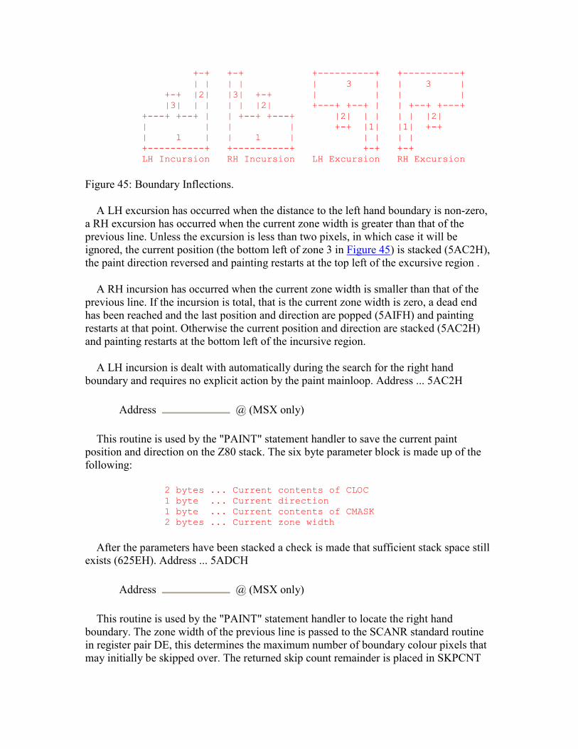
+-+ +-+ +----------+ +----------+ | | | | | 3 | | 3 | +-+ |2| |3| +-+ | | | | |3| | | | | |2| +---+ +--+ | | +--+ +---+ +---+ +--+ | | +--+ +---+ |2| | | | | |2| | | | | +-+ |1| |1| +-+ | 1 | | 1 | | | | | +----------+ +----------+ +-+ +-+ LH Incursion RH Incursion LH Excursion RH Excursion
Figure 45: Boundary Inflections.
A LH excursion has occurred when the distance to the left hand boundary is non-zero, a RH excursion has occurred when the current zone width is greater than that of the previous line. Unless the excursion is less than two pixels, in which case it will be ignored, the current position (the bottom left of zone 3 in Figure 45) is stacked (5AC2H), the paint direction reversed and painting restarts at the top left of the excursive region .
A RH incursion has occurred when the current zone width is smaller than that of the previous line. If the incursion is total, that is the current zone width is zero, a dead end has been reached and the last position and direction are popped (5AIFH) and painting restarts at that point. Otherwise the current position and direction are stacked (5AC2H) and painting restarts at the bottom left of the incursive region.
A LH incursion is dealt with automatically during the search for the right hand boundary and requires no explicit action by the paint mainloop. Address ... 5AC2H
Address @ (MSX only)
This routine is used by the "PAINT" statement handler to save the current paint position and direction on the Z80 stack. The six byte parameter block is made up of the following:
2 bytes ... Current contents of CLOC 1 byte ... Current direction 1 byte ... Current contents of CMASK 2 bytes ... Current zone width
After the parameters have been stacked a check is made that sufficient stack space still exists (625EH). Address ... 5ADCH
Address @ (MSX only)
This routine is used by the "PAINT" statement handler to locate the right hand boundary. The zone width of the previous line is passed to the SCANR standard routine in register pair DE, this determines the maximum number of boundary colour pixels that may initially be skipped over. The returned skip count remainder is placed in SKPCNT
and the number of non- boundary colour pixels traversed in MOVCNT. Address ... 5AEDH
Address @ (MSX only)
This routine is used by the "PAINT" statement handler to locate the left hand boundary. The end point of the right hand boundary search is temporarily saved and the starting point taken from CSAVEA and CSAVEM and made the current pixel physical address. The left hand boundary is then located via the SCANL standard routine, which also fills in the entire zone, and the right hand end point recovered and placed in CSAVEA and CSAVEM. - 149 - 5. ROM BASIC INTERPRETER Address ... 5B0BH
Address @ (MSX only)
This routine is used by the "CIRCLE" statement handler to negate the contents of register pair DE. Address ... 5B11H
Address @ (MSX only)
This is the "CIRCLE" statement handler. After evaluating the centre coordinate pair (579CH) the radius is evaluated (520FH), multiplied (325CH) by SIN(PI/4) and placed in CNPNTS. The ink colour is set (584DH), the start angle evaluated (5D17H) and placed in CSTCNT and the end angle evaluated (5D17H) and placed in CENCNT. If the end angle is smaller than the start angle the two values are swapped and CPLOTF is made non-zero. The aspect ratio is evaluated (4C64H) and, if it is greater than one, its reciprocal is taken (3267H) and CSCLXY is made non-zero to indicate an X axis squash. The aspect ratio is multiplied (325CH) by 256, converted to an integer (2F8AH) and placed in ASPECT as a single byte binary fraction. Register pairs HL and DE are set to the starting position on the circle perimeter (X=RADIUS,Y=0) and control drops into the circle mainloop. Address ... 5BBDH
Address @ (MSX only)
This is the circle mainloop. Because of the high degree of symmetry in a circle it is only necessary to compute the coordinates of the arc from zero to forty-five degrees. The other seven segments are produced by rotation and reflection of these points. The parametric equation for a unit circle, with T the angle from zero to PI/4, is:
X=COS(T) Y=SIN(T)
Direct computation using this equation, or the corresponding functional form X=SQR(1-Y^2), is too slow, instead the first derivative is used:
dx
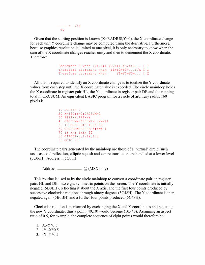
---- = -Y/X dy
Given that the starting position is known (X=RADIUS,Y=0), the X coordinate change for each unit Y coordinate change may be computed using the derivative. Furthermore, because graphics resolution is limited to one pixel, it is only necessary to know when the sum of the X coordinate changes reaches unity and then to decrement the X coordinate. Therefore:
Decrement X when (Y1/X)+(Y2/X)+(Y3/X)+... ^ 1 Therefore decrement when (Y1+Y2+Y3+...)/X ^ 1 Therefore decrement when Y1+Y2+Y3+... ^ X
All that is required to identify an X coordinate change is to totalize the Y coordinate values from each step until the X coordinate value is exceeded. The circle mainloop holds the X coordinate in register pair HL, the Y coordinate in register pair DE and the running total in CRCSUM. An equivalent BASIC program for a circle of arbitrary radius 160 pixels is:
10 SCREEN 2 20 X=160:Y=0:CRCSUM=0 30 PSET(X,191-Y) 40 CRCSUM=CRCSUM+Y :Y=Y+1 50 IF CRCSUM<X THEN 30 60 CRCSUM=CRCSUM-X:X=X-1 70 IF X>Y THEN 30 80 CIRCLE(0,191),155 90 GOTO 90
The coordinate pairs generated by the mainloop are those of a "virtual" circle, such tasks as axial reflection, elliptic squash and centre translation are handled at a lower level (5C06H). Address ... 5C06H
Address @ (MSX only)
This routine is used to by the circle mainloop to convert a coordinate pair, in register pairs HL and DE, into eight symmetric points on the screen. The Y coordinate is initially negated (5B0BH), reflecting it about the X axis, and the first four points produced by successive clockwise rotations through ninety degrees (5C48H). The Y coordinate is then negated again (5B0BH) and a further four points produced (5C48H).
Clockwise rotation is performed by exchanging the X and Y coordinates and negating the new Y coordinate, thus a point (40,10) would become (10,-40). Assuming an aspect ratio of 0.5, for example, the complete sequence of eight points would therefore be:
1. X,-Y*0.5 2. -Y,-X*0.5 3. -X, Y*0.5
4. Y, X*0.5 5. Y,-X*0.5 6. -X,-Y*0.5 7. -Y, X*0.5 8. X, Y*0.5
It can be seen from the above that, ignoring the sign of the coordinates for the moment, there are only four terms involved. Therefore, rather than performing the relatively slow aspect ratio multiplication (5CEBH) for each point, the terms X*0.5 and Y*0.5 can be prepared in advance and the complete sequence generated by interchanging and negating the four terms. With the aspect ratio shown above the initial conditions are set up so that register pair HL=X, register pair DE= -Y*0.5, CXOFF=Y and CYOFF=X*0.5 and successive points are produced by the operations:
1. Exchange HL and CXOFF, negate HL. 2. Exchange DE and CYOFF, negate DE.
In parallel with the computation of each circle coordinate the number of points required to reach the start of the segment containing the point is kept in CPCNT8. This will initially be zero and will increase by 2*RADIUS*SIN(PI/4) as each ninety degree rotation is made. As each of the eight points is produced its Y coordinate value is added to the contents of CPCNT8 and compared to the start and end angles to determine the appropriate course of action. If the point is between the two angles and CPLOTF is zero, or if it is outside the angles and CPLOTF is non-zero, the coordinates are added to the circle centre coordinates (5CDCH) and the point set via the SCALXY, MAPXYC and SETC standard routines. If the point is equal to either of the two angles, and the associated bit is set in CLINEF, the coordinates are added to the circle centre coordinates (5CDCH) and a line drawn to the centre (593CH). If none of these conditions is applicable no action is taken other than to proceed to the next point. Address ... 5CEBH
Address @ (MSX only)
This routine multiplies the coordinate value supplied in register pair DE by the aspect ratio contained in ASPECT, the result is returned in register pair DE. The standard binary shift and add method is used but the operation is performed as two single byte multiplications to avoid overflow problems. Address ... 5D17H
Address @ (MSX only)
This routine is used by the "CIRCLE" statement handler to convert an angle operand to the form required by the circle mainloop, the result is returned in register pair DE. While the method used is basically sound, and eliminates one trigonometric computation per angle, the results produced are inaccurate. This is demonstrated by the following example which draws a line to the true thirty degree point on a circle's perimeter:
10 SCREEN 2
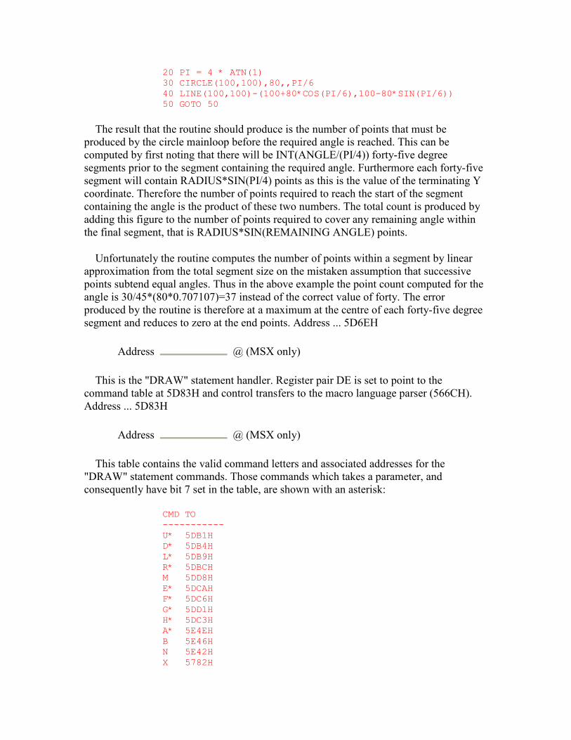
20 PI = 4 * ATN(1) 30 CIRCLE(100,100),80,,PI/6 40 LINE(100,100)-(100+80*COS(PI/6),100-80*SIN(PI/6)) 50 GOTO 50
The result that the routine should produce is the number of points that must be produced by the circle mainloop before the required angle is reached. This can be computed by first noting that there will be INT(ANGLE/(PI/4)) forty-five degree segments prior to the segment containing the required angle. Furthermore each forty-five segment will contain RADIUS*SIN(PI/4) points as this is the value of the terminating Y coordinate. Therefore the number of points required to reach the start of the segment containing the angle is the product of these two numbers. The total count is produced by adding this figure to the number of points required to cover any remaining angle within the final segment, that is RADIUS*SIN(REMAINING ANGLE) points.
Unfortunately the routine computes the number of points within a segment by linear approximation from the total segment size on the mistaken assumption that successive points subtend equal angles. Thus in the above example the point count computed for the angle is 30/45*(80*0.707107)=37 instead of the correct value of forty. The error produced by the routine is therefore at a maximum at the centre of each forty-five degree segment and reduces to zero at the end points. Address ... 5D6EH
Address @ (MSX only)
This is the "DRAW" statement handler. Register pair DE is set to point to the command table at 5D83H and control transfers to the macro language parser (566CH). Address ... 5D83H
Address @ (MSX only)
This table contains the valid command letters and associated addresses for the "DRAW" statement commands. Those commands which takes a parameter, and consequently have bit 7 set in the table, are shown with an asterisk:
CMD TO ----------- U* 5DB1H D* 5DB4H L* 5DB9H R* 5DBCH M 5DD8H E* 5DCAH F* 5DC6H G* 5DD1H H* 5DC3H A* 5E4EH B 5E46H N 5E42H X 5782H
C* 5E87H S* 5E59H
Address ... 5DB1H Address @ (MSX only)
This is the "DRAW" statement "U" command handler. The operation of the "D", "L", "R", "E", "F", "G" and "H" commands is very similar so no separate description of their handlers is given. The optional numeric parameter is supplied by the macro language parser in register pair DE. This initial parameter is modified by a given handler into a horizontal offset in register pair BC and a vertical offset in register pair DE. For example if leftward or upward movement is required the parameter is negated (5B0BH), if diagonal movement is required the parameter is duplicated so that equal horizontal and vertical offsets are produced. Once the offsets have been prepared control transfers to the line drawing routine (5DFFH). Address ... 5DD8H
Address @ (MSX only)
This is the "DRAW" statement "M" command handler. The character following the command letter is examined then the two parameters collected from the command string (5719H). If the initial character is "+" or "-" the parameters are regarded as offsets and are scaled (5E66H), rotated through successive ninety degree steps as determined by DRWANG and then added to the current graphics coordinates (5CDCH) to determine the termination point. If DRWFLG shows the "B" mode to be inactive a line is then drawn (5CCDH) from the current graphics coordinates to the termination point. If DRWFLG shows the "N" mode to be inactive the termination coordinates are placed in GRPACX and GRPACY to become the new current graphics coordinates. Finally DRWFLG is zeroed, turning the "B" and "N" modes off, and the handler terminates. Address ... 5E42H
Address @ (MSX only)
This is the "DRAW" statement "N" command handler, DRWFLG is simply set to 40H. Address ... 5E46H
Address @ (MSX only)
This is the "DRAW" statement "B" command handler, DRWFLG is simply set to 80H. Address ... 5E4EH
Address @ (MSX only)
This is the "DRAW" statement "A" command handler. The parameter is checked for magnitude and placed in DRWANG. Address ... 5E59H
Address @ (MSX only)
This is the "DRAW" statement "S" command handler. The parameter is checked for magnitude and placed in DRWSCL. Address ... 5E66H
Address @ (MSX only)
This routine is used by the "DRAW" statement "U", "D", "L", "R", "E", "F", "G", "H" and "M" (in offset mode) command handlers to scale the offset supplied in register pair DE by the contents of DRWSCL. Unless DRWSCL is zero, in which case the routine simply terminates, the offset is multiplied using repeated addition and then divided by four (59B4H). To eliminate scaling an "S0" or "S4" command should be used. - 154 - 5. ROM BASIC INTERPRETER Address ... 5E87H
Address @ (MSX only)
This is the "DRAW" statement "C" command handler. The parameter is placed in ATRBYT via the SETATR standard routine. There is no check on the MSB of the parameter so illegal values such as "C265" will be accepted without an error message. Address ... 5E91H
Address @ (MSX only)
This routine is used by the "PAINT" statement handler to check, via the SCALXY standard routine, that the coordinates in register pairs BC and DE are within the screen. If not an "Illegal function call" error is generated (475AH). Address ... 5E9FH
Address @ (MSX only)
This is the "DIM" statement handler. A return is set up to 5E9AH, so that multiple Arrays can be processed, DIMFLG is made non-zero and control drops into the Variable search routine.
Address ... 5EA4H Name ...... PTRGET (Pointer Get) Input ..... HL=program address, SUBFLG=0 single variable else array Exit ...... HL=next address, DE=pointer to the first variable Modifies .. All registers
This is the Variable search routine. On entry register pair HL points to the first character of the Variable name in the program text. On exit register pair HL points to the character following the name and register pair DE to the first byte of the Variable contents in the Variable Storage Area. The first character of the name is taken from the program text, checked to ensure that it is upper case alphabetic (64A7H) and placed in register C. The optional second character, with a default value of zero, is placed in register B, this character may be alphabetic or numeric. Any further alphanumeric characters are then simply skipped over. If a type suffix character ("%", "$", "!" or "#")
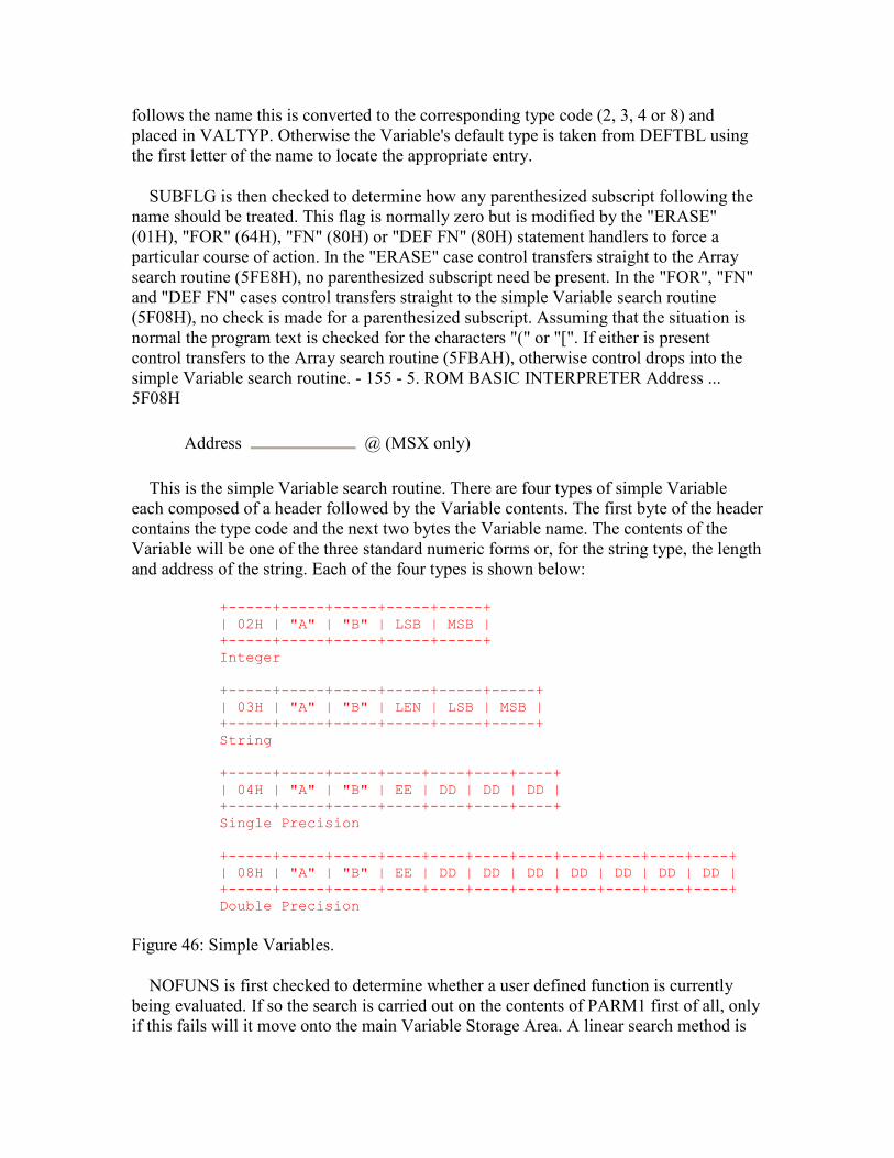
follows the name this is converted to the corresponding type code (2, 3, 4 or 8) and placed in VALTYP. Otherwise the Variable's default type is taken from DEFTBL using the first letter of the name to locate the appropriate entry.
SUBFLG is then checked to determine how any parenthesized subscript following the name should be treated. This flag is normally zero but is modified by the "ERASE" (01H), "FOR" (64H), "FN" (80H) or "DEF FN" (80H) statement handlers to force a particular course of action. In the "ERASE" case control transfers straight to the Array search routine (5FE8H), no parenthesized subscript need be present. In the "FOR", "FN" and "DEF FN" cases control transfers straight to the simple Variable search routine (5F08H), no check is made for a parenthesized subscript. Assuming that the situation is normal the program text is checked for the characters "(" or "[". If either is present control transfers to the Array search routine (5FBAH), otherwise control drops into the simple Variable search routine. - 155 - 5. ROM BASIC INTERPRETER Address ... 5F08H
Address @ (MSX only)
This is the simple Variable search routine. There are four types of simple Variable each composed of a header followed by the Variable contents. The first byte of the header contains the type code and the next two bytes the Variable name. The contents of the Variable will be one of the three standard numeric forms or, for the string type, the length and address of the string. Each of the four types is shown below:
+-----+-----+-----+-----+-----+ | 02H | "A" | "B" | LSB | MSB | +-----+-----+-----+-----+-----+ Integer +-----+-----+-----+-----+-----+-----+ | 03H | "A" | "B" | LEN | LSB | MSB | +-----+-----+-----+-----+-----+-----+ String +-----+-----+-----+----+----+----+----+ | 04H | "A" | "B" | EE | DD | DD | DD | +-----+-----+-----+----+----+----+----+ Single Precision +-----+-----+-----+----+----+----+----+----+----+----+----+ | 08H | "A" | "B" | EE | DD | DD | DD | DD | DD | DD | DD | +-----+-----+-----+----+----+----+----+----+----+----+----+ Double Precision
Figure 46: Simple Variables.
NOFUNS is first checked to determine whether a user defined function is currently being evaluated. If so the search is carried out on the contents of PARM1 first of all, only if this fails will it move onto the main Variable Storage Area. A linear search method is

used, the two name characters and type byte of each Variable in the storage area are compared to the reference characters and type until a match is found or the end of the storage area is reached. If the search is successful the routine terminates with the address of the first byte of the Variable contents in register pair DE. If the search is unsuccessful the Array Storage Area is moved upwards and the new Variable is added to the end of the existing ones and initialized to zero.
There are two exceptions to this automatic creation of a new Variable. If the search is being carried out by the "VARPTR" function, and this is determined by examining the return address, no Variable will be created. Instead the routine terminates with register pair DE set to zero (5F61H) causing a subsequent "Illegal function call" error. The second exception occurs when the search is being carried out by the Factor Evaluator, that is when the Variable is newly declared inside an expression. In this case DAC is zeroed for numeric types, and loaded with the address of a dummy zero length descriptor for a string type, thus returning a zero result (5FA7H). These actions are designed to prevent the Expression Evaluator creating a new Variable ("VARPTR") is the only function to take a Variable argument directly rather than via an expression and so requires separate protection). If this were not so then assignment to an Array, via the "LET" statement handler, would fail as any simple Variable created during expression evaluation would change the Array's address. Address ... 5FBAH
Address @ (MSX only)
This is the Array search routine. There are four types of Array each composed of a header plus a number of elements. The first byte of the header contains the type code, the next two bytes the Array name and the next two the offset to the start of the following Array. This is followed by a single byte containing the dimensionality of the Array and the element count list. Each two byte element count contains the maximum number of elements per dimension. These are stored in reverse order with the first one corresponding to the last subscript. The contents of each Array element are identical to the contents of the corresponding simple Variable. The integer Array AB%(3,4) is shown below with each element identified by its subscripts, high memory is towards the top of the page:
+-----------------------+ |(0,4) (1,4) (2,4) (3,4)| |(0,3) (1,3) (2,3) (3,3)| |(0,2) (1,2) (2,2) (3,2)| |(0,1) (1,1) (2,1) (3,1)| |(0,0) (1,0) (2,0) (3,0)| +-----------------------+ +-----+-----+-----+-----------+-----+-----------+-----------+ | | | | Offset | Dim | Count | Count | | 02H | "A" | "B" | 2DH 00H | 02H | 05H 00H | 04H 00H | +-----+-----+-----+-----------+-----+-----------+-----------+
Figure 47: Integer Array.
Each subscript is evaluated, converted to an integer (4755H) and pushed onto the Z80 stack until a closing parenthesis is found, it need not match the opening one. A linear search is then carried out on the Array Storage Area for a match with the two name characters and the type. If the search is successful DIMFLG is checked and a "Redimensioned array" error generated (405EH) if it shows a "DIM" statement to be active. Unless an "ERASE" statement is active, in which case the routine terminates with register pair BC pointing to the start of the Array (3297H), the dimensionality of the Array is then checked against the subscript count and a "Subscript out of range" error generated if they fail to match. Assuming these tests are passed control transfers to the element address computation point (607DH).
If the search is unsuccessful and an "ERASE" statement is active an "Illegal function call" error is generated (475AH), otherwise the new Array is added to the end of the existing Array Storage Area. Initialization of the new Array proceeds by storing the two name characters, the type code and the dimensionality (the subscript count) followed by the element count for each dimension. If DIMFLG shows a "DIM" statement to be active the element counts are determined by the subscripts. If the Array is being created by default, with a statement such as "A(1,2,3)=5" for example, a default value of eleven is used. As each element count is stored the total size of the Array is accumulated in register pair DE by successive multiplications (314AH) of the element counts and the element size (the Array type). After a check that this amount of memory is available (6267H) STREND is increased the new area is zeroed and the Array size is stored, in slightly modified form, immediately after the two name characters. Unless the Array is being created by default, in which case the element address must be computed, the routine then terminates.
This is the element address computation point of the Array search routine. The location of a particular element within an Array involves the multiplication (314AH) of subscripts, element counts and element sizes. As there are a variety of ways this could be done the actual method used is best illustrated with an example. The location of element (1,2,3) in a 4*5*6 Array would initially be computed as (((3*5)+2)*4)+1. This is then multiplied by the element size (type) and added to the Array base address to obtain the address of the required element. The computation method is an optimized form which minimizes the number of steps needed, it is equivalent to evaluating (3*(4*5))+(2*4)+(1). The element address is returned in register pair DE. Address ... 60B1H
Address @ (MSX only)
This is the "PRINT USING" statement handler. Control transfers here from the general "PRINT" statement handler after the applicable output device has been set up. Upon termination control passes back to the general "PRINT" statement exit point (4AFFH) to restore the normal video output. The format string is evaluated (4C65H) and the address and length of the string body obtained from the descriptor. The program text pointer is then temporarily saved. Each character of the format string is examined until one of the possible template characters is found. If the character does not belong in a template it is simply output via the OUTDO standard routine. Once the start of a template is found this
is scanned along until a non-template character is found. Control then passes to the numeric output routine (6192H) or the string output routine (6211H).
In either case the program text pointer is restored to register pair HL and the next operand evaluated (4C64H). For numeric output the information gained from the template scan is passed to the numeric conversion routine (3426H) in registers A, B and C and the resulting string displayed (6678H). For string output the required character count is passed to the "LEFT$" statement handler (6868H) in register C and the resulting string displayed (667BH). For either type of output the program text and format string are then examined to determine whether there are any further characters. If no operands exist the handler terminates. If the format string has been exhausted then it is restarted from the beginning (60BFH), otherwise scanning continues from the current position for the next operand (60f6H). Address ... 6250H
Address @ (MSX only)
This routine is used by the Interpreter Mainloop and the Variable search routine to move a block of memory upwards. A check is first made to ensure that sufficient memory exists (6267H) and then the block of memory is moved. The top source address is supplied in register pair BC and the top destination address in register pair HL. Copying stops when the contents of register pair BC equal those of register pair DE. Address ... 625EH
Address @ (MSX only)
This routine is used to check that sufficient memory is available between the top of the Array Storage Area and the base of the Z80 stack. On entry register C contains the number of words the caller requires. If this would narrow the gap to less than two hundred bytes an "Out of memory" error is generated. Address ... 6286H
Address @ (MSX only)
This is the "NEW" statement handler. TRCFLG, AUTFLG and PTRFLG are zeroed and the zero end link is placed at the start of the Program Text Area. VARTAB is set to point to the byte following the end link and control drops into the run-clear routine. Address ... 629AH
Address @ (MSX only)
This routine is used by the "NEW", "RUN" and "CLEAR" statement handlers to initialize the Interpreter variables. All interrupts are cleared (636EH) and the default Variable types in DEFTBL set to double precision. RNDX is reset (2C24H) and ONEFLG, ONELIN and OLDTXT are zeroed. MEMSIZ is copied to FRETOP to clear the String Storage Area and DATPTR set to the start of the Program Text Area (63C9H). The contents of VARTAB are copied into ARYTAB and STREND, to clear any
Variables, all the I/O buffers are closed (6C1CH) and NLONLY is reset. SAVSTK and the Z80 SP are reset from STKTOP and TEMPPT is reset to the start of TEMPST to clear any string descriptors. The printer is shut down (7304H) and output restored to the screen (4AFFH). Finally PRMLEN, NOFUNS, PRMLN2, FUNACT, PRMSTK and SUBFLG are zeroed and the routine terminates. - 159 - 5. ROM BASIC INTERPRETER Address ... 631BH
Address @ (MSX only)
This routine is used by the "DEVICE ON" statement handlers to enable an interrupt source, the address of the relevant device's TRPTBI. status byte is supplied in register pair HL. Interrupts are enabled by setting bit 0 of the status byte. Bits 1 and 2 are then examined and, if the device has been stopped and an interrupt has occurred, ONGSBF is incremented (634FH) so that the Runloop will process it at the end of the statement. Finally bit 1 of the status byte is reset to release any existing stop condition. Address ... 632EH
Address @ (MSX only)
This routine is used by the "DEVICE OFF" statement handlers to disable an interrupt source, the address of the relevant device's TRPTBL status byte is supplied in register pair HL. Bits 0 and 2 are examined to determine whether an interrupt has occurred since the end of the last statement, if so ONGSBF is decremented (6362H) to prevent the Runloop from picking it up. The status byte is then zeroed. Address ... 6331H
Address @ (MSX only)
This routine is used by the "DEVICE STOP" statement handlers to suspend processing of interrupts from an interrupt source, the address of the relevant device's TRPTBL status byte is supplied in register pair HL. Bits 0 and 2 are examined to determine whether an interrupt has occurred since the end of the last statement, if so ONGSBF is decremented (6362H) to prevent the Runloop from picking it up. Bit 1 of the status byte is then set. Address ... 633EH
Address @ (MSX only)
This routine is used by the "RETURN" statement handler to release the temporary stop condition imposed during interrupt driven BASIC subroutines, the address of the relevant device's TRPTBL status byte is supplied in register pair HL. Bits 0, and 2 are examined to determine whether a stopped interrupt has occurred since the subroutine was first activated. If so ONGSBF is incremented (634FH) so that the Runloop will pick it up at the end of the statement. Bit 1 of the status byte is then reset. It should be noted that any "DEVICE STOP" Statement within an interrupt driven subroutine will therefore be ineffective. Address ... 6358H
Address @ (MSX only)
This routine is used by the Runloop interrupt processor (6389H) to clear an interrupt prior to activating the BASIC subroutine, the address of the relevant device's TRPTBL status byte is supplied in register pair HL. ONGSBF is decremented and bit 2 of the status byte is reset. - 160 - 5. ROM BASIC INTERPRETER Address ... 636EH
Address @ (MSX only)
This routine is used by the run-clear routine (629AH) to clear all interrupts. The seventy-eight bytes of TRPTBL and the ten bytes of FNKFLG are zeroed. Address ... 6389H
Address @ (MSX only)
This is the Runloop interrupt processor. ONEFLG is first examined to determine whether an error condition currently exists. If so the routine terminates, no interrupts will be processed until the error clears. CURLIN is then examined and, if the Interpreter is in direct mode, the routine terminates. Assuming all is well a search is made of the twenty-six status bytes in TRPTBL to find the first active interrupt. Note that devices near the start of the table will consequently have a higher priority than those lower down. When the first active status byte is found, that is one with bits 0 and 2 set, the associated address is taken from TRPTBL and placed in register pair DE. The interrupt is then cleared (6358H) and the device stopped (6331H) before control transfers to the "GOSUB" handler (47CFH). Address ... 63C9H
Address @ (MSX only)
This is the "RESTORE" statement handler. If no line number operand exists DATPTR is set to the start of the Program Storage Area. Otherwise the operand is collected (4769H), the program text searched to find the relevant line (4295H) and its address placed in DATPTR. Address ... 63E3H
Address @ (MSX only)
This is the "STOP" statement handler. If further text exists in the statement control transfers to the "STOP ON/OFF/STOP" statement handler (77A5H). Otherwise register A is set to 01H and control drops into the "END" statement handler. Address ... 63EAH
Address @ (MSX only)
This is the "END" statement handler. It is also used, with differing entry points, by the "STOP" statement and for CTRL- STOP and end of text program termination. ONEFLG is first zeroed and then, for the "END" statement only, all I/O buffers are closed

(6C1CH). The current program text position is placed in SAVTXT and OLDTXT and the current line number in OLDLIN for use by any subsequent "CONT" statement. The printer is shut down (7304H), a CR LF issued to the screen (7323H) and register pair HL set to point to the "Break" message at 3FDCH. For the "END" statement and end of text cases control then transfers to the Mainloop "OK" point (411EH). For the CTRL-STOP case control transfers to the end of the error handler (40FDH) to display the "Break" message. - 161 - 5. ROM BASIC INTERPRETER Address ... 6424H
Address @ (MSX only)
This is the "CONT" statement handler. Unless they are zero, in which case a "Can't CONTINUE" error is generated, the contents of OLDTXT are placed in register pair HL and those of OLDLIN in CURLIN. Control then returns to the Runloop to execute at the old program text position. A program cannot be continued after CTRL-STOP has been used to break from WITHIN a statement, via the CKCNTC standard routine, rather than from between statements. Address ... 6438H
Address @ (MSX only)
This is the "TRON" statement handler, TRCFLG is simply made non-zero. Address ... 6439H
Address @ (MSX only)
This is the "TROFF" statement handler, TRCFLG is simply made zero. Address ... 643EH
Address @ (MSX only)
This is the "SWAP" statement handler. The first Variable is located (PTRGET, 5EA4H) and its contents copied to SWPTMP. The location of this Variable and of the end of the Variable Storage Area are temporarily saved. The second Variable is then located (PTRGET, 5EA4H) and its type compared with that of the first. If the types fail to match a "Type mismatch" error is generated (406DH). The current end of the Variable Storage Area is then compared with the old end and an "Illegal function call" error generated (475AH) if they differ. Finally the contents of the second Variable are copied to the location of the first Variable (2EF3H) and the contents of SWPTMP to the location of the second Variable (2EF3H).
The checks performed by the handler mean that the second Variable, if it is simple and not an Array, must always be in existence before a "SWAP" Statement is encountered or an error will be generated. The reason for this is that, supposing the first Variable was an Array, then the creation of a second (simple) Variable would move the Array Storage Area upwards invalidating its saved location. Note that the perfectly legal case of a
simple first Variable and a newly created simple second Variable is also rejected. Address ... 6477H
Address @ (MSX only)
This is the "ERASE" statement handler. SUBFLG is first set to 01H, to control the Variable search routine, and the Array located (PTRGET, 5EA4H). All the following Arrays are moved downward and STREND set to its new, lower value. The program text is then checked and, if a comma follows, control transfers back to the start of the handler. - 162 - 5. ROM BASIC INTERPRETER Address ... 64A7H
Address @ (MSX only)
This routine checks whether the character whose address is supplied in register pair HL is upper case alphabetic, if so it returns Flag NC. Address ... 64AFH
Address @ (MSX only)
This is the "CLEAR" statement handler. If no operands are present control transfers to the run-clear routine (62A1H) to remove all current Variables. Otherwise the string space operand is evaluated (4756H) followed by the optional top of memory operand (FRMQNT, 542FH). The top of memory value is checked and an "Illegal function call" error generated (475AH) if it is less than 8000H or greater than F380H. The space required by the I/O buffers (267 bytes each) and the String Storage Area is subtracted from the top of memory value and an "Out of memory" error generated (6275H) if there is less than 160 bytes remaining to the base of the Variable Storage Area. Assuming all is well HIMEM, MEMSIZ and STKTOP are set to their new values and the remaining storage pointers reset via the run- clear routine (62A1H). The I/O buffer storage is re-allocated (7E6BH) and the handler terminates.
Unfortunately the computation of MEMSIZ and STKTOP, when a new top of memory is specified, is incorrect resulting in the top of the String Storage Area being set one byte too high. This can be seen with the following where an illegal string is accepted:
10 CLEAR 200,&HF380 20 A$=STRING$(201,"A") 30 PRINT FRE("")
Because there should be an extra DEC HL instruction at 64EBH the new values of MEMSIZ and STKTOP are initially set one byte too high. When the run-clear routine is called MEMSIZ is copied into FRETOP, the top of the String Storage Area, which results in this being one byte too high as well. Although MEMSIZ and STKTOP are correctly recomputed when the file pointers are reset, FRETOP is left with its incorrect value. When the "FRE" statement is executed in line thirty, and string garbage collection initiated, FRETOP is restored to its correct value but, because the string overflows the String Storage Area by one byte, the amount of free space displayed is -1 byte. To
correctly set all the system pointers any alteration of the top of memory should be followed immediately by another "CLEAR" statement with no operands. Address ... 6520H
Address @ (MSX only)
This routine computes the difference between the contents of register pairs HL and DE. It is a duplicate of the short section of code from 64ECH to 64F1H and is completely unused. - 163 - 5. ROM BASIC INTERPRETER Address ... 6527H
Address @ (MSX only)
This is the "NEXT" statement handler. Assuming further text is present in the statement the loop Variable is located (PTRGET, 5EA4H), otherwise a default address of zero is taken. The stack is then searched for the corresponding "FOR" parameter block (3FE2H). If no parameter block is found, or if a "GOSUB" parameter block is found first, a "NEXT without FOR" error is generated (405BH). Assuming the parameter block is found the intervening section of stack, together with any "FOR" blocks it may contain, is discarded. The loop Variable type is then taken from the parameter block and examined to determine the precision required during subsequent operations.
The STEP value is taken from the parameter block and added (3172H, 324EH or 2697H) to the current contents of the loop Variable which is then updated. The new value is compared (2F4DH, 2F21H or 2F5CH) with the termination value from the parameter block to determine whether the loop has terminated (65B6H). The loop will terminate for a positive STEP if the new loop value is GREATER than the termination value. The loop will terminate for a negative step if the new loop value is LESS than the termination value. If the loop has not terminated the original program text position and line number are taken from the parameter block and control transfers to the Runloop (45FDH). If the loop has terminated the parameter block is discarded from the stack and, unless further program text is present in which control transfers back to the start of the handler, control transfers to the Runloop to execute the next statement (NEWSTT, 4601H). Address ... 65C8H
Address @ (MSX only)
This routine is used by the Expression Evaluator to find the relation (<>=) between two string operands. The address of the first string descriptor is supplied on the Z80 stack and the address of the second in DAC. The result is returned in register A and the flags as for the numeric relation routines:
String 1=String 2 ... A=00H, Flag Z, NC String 1<String 2 ... A=01H, Flag NZ, NC String 1>String 2 ... A=FFH, Flag NZ, C
Comparison commences at the first character of each string and continues until the two characters differ or one of the strings is exhausted. Control then returns to the Expression Evaluator (4F57H) to place the true or false numeric result in DAC. Address ... 65F5H
Address @ (MSX only)
This routine is used by the Factor Evaluator to apply the "OCT$" function to an operand contained in DAC. The number is first converted to textual form in FBUFFR (371EH) and then the result string is created (6607H). - 164 - 5. ROM BASIC INTERPRETER Address ... 65FAH
Address @ (MSX only)
This routine is used by the Factor Evaluator to apply the "HEX$" function to an operand contained in DAC. The number is first converted to textual form in FBUFFR (3722H) and then the result string is created (6607H). Address ... 65FFH
Address @ (MSX only)
This routine is used by the Factor Evaluator to apply the "BIN$" function to an operand contained in DAC. The number is first converted to textual form in FBUFFR (371AH) and then the result string is created (6607H). Address ... 6604H
Address @ (MSX only)
This routine is used by the Factor Evaluator to apply the "STR$" function to an operand contained in DAC. The number is first converted to textual form in FBUFFR (3425H) then analyzed to determine its length and address (6635H). After checking that sufficient space is available (668EH) the string is copied to the String Storage Area (67C7H) and the result descriptor created (6654H). Address ... 6627H
Address @ (MSX only)
This routine first checks that there is sufficient space in the String Storage Area for the string whose length is supplied in register A (668EH). The string length and the address where the string will be placed in the String Storage Area are then copied to DSCTMP. Address ... 6636H
Address @ (MSX only)
This routine is used by the Factor Evaluator to analyze the character string whose address is supplied in register pair HL. The character string is scanned until a terminating character (00H or ") is found. The length and starting address are then placed in
DSCTMP (662AH) and control drops into the descriptor creation routine. Address ... 6654H
Address @ (MSX only)
This routine is used by the string functions to create a result descriptor. The descriptor is copied from DSCTMP to the next available position in TEMPST and its address placed in DAC. Unless TEMPST is full, in which case a "String formula too complex" error is generated, TEMPPT is increased by three bytes and the routine terminates. Address ... 6678H
Address @ (MSX only)
This routine displays the message, or string, whose address is supplied in register pair HL. The string is analyzed (6635H) and its storage freed (67D3H). Successive characters are then taken from the string and displayed, via the OUTDO standard routine, until the string is exhausted. Address ... 668EH
Address @ (MSX only)
This routine checks that there is room in the String Storage Area to add the string whose length is supplied in register A. On exit register pair DE points to the starting address in the String Storage Area where the string should be placed. The length of the string is first subtracted from the current free location contained in FRETOP. This is then compared with STKTOP, the lowest allowable location for string storage, to determine whether there is space for the string. If so FRETOP is updated with the new position and the routine terminates. If there is insufficient space for the string then garbage collection is initiated (66B6H) to try and eliminate any dead strings. If, after garbage collection, there is still not enough space an "Out of string space" error is generated. Address ... 66B6H
Address @ (MSX only)
This is the string garbage collector, its function is to eliminate any dead strings from the String Storage Area. The basic problem with string Variables, as opposed to numeric ones, is that their lengths vary. If string bodies were stored with their Variables in the Variable Storage Area even such apparently simple statements as A$=A$+"X" would require the movement of thousands of bytes of memory and slow execution speeds dramatically. The method used by the Interpreter to overcome this problem is to keep the string bodies separate from the Variables. Thus strings are kept in the String Storage Area and each Variable holds a three byte descriptor containing the length and address of the associated string. Whenever a string is assigned to a Variable it is simply added to the heap of existing strings in the String Storage Area and the Variable's descriptor changed. No attempt is made to eliminate any previous string belonging to the Variable, by restructuring the heap, as this would wipe out any throughput gains.
If sufficient Variable assignments are made it is inevitable that the String Storage Area will fill up. In a typical program many of these strings will be unused, that is the result of previous assignments. Garbage collection is the process whereby these dead strings are removed. Every string Variable in memory, including Arrays and the local Variables present during evaluation of user defined functions, is examined until the one is found whose string is stored highest in the heap. This string is then moved to the top of the String Storage Area and the Variable contents modified to point to the new location. The owner of the next highest string is then found and the process repeated until every string belonging to a Variable has been compacted. - 166 - 5. ROM BASIC INTERPRETER
If a large number of Variables are present garbage collection may take an appreciable time. The process can be seen at work with the following program which repeatedly assigns the string "AAAA" to each element of the Array A$. The program will run at full speed for the first two hundred and fifty assignments and then pause to eliminate the fifty dead strings. A further fifty assignments can then be made before a further garbage collection is required: 10 CLEAR 1000 20 DIM A$(200) 30 FOR N=0 TO 200 40 A$(N)=STRING$(4,"A") 50 PRINT"."; 60 NEXT N 70 GOTO 30
The String Storage Area is also used to hold the intermediate strings produced during expression evaluation. Because so many string functions take multiple arguments, "MID$" takes three for example, the management of intermediate results is a major problem. To deal with it a standardized approach to string results is taken throughout the Interpreter. A producer of a string simply adds the string body to the heap in the String Storage Area, adds the descriptor to the descriptor heap in TEMPST and places the address of the descriptor in DAC. It is up to the user of the result to free this storage (FRESTR, 67D0H) once it has processed the string. This rule applies to all parts of the system, from the individual function handlers back through the Expression Evaluator to the statement handlers, with only two exceptions.
The first exception occurs when the Factor Evaluator finds an explicitly stated string, such as "SOMETHING" in the program text. In this case it is not necessary to copy the string to the String Storage Area as the original will suffice.
The second exception occurs when the Factor Evaluator finds a reference to a Variable. In this case it is not necessary to place a copy of the descriptor in TEMPST as one already exists inside the Variable. Address ... 6787H
Address @ (MSX only)
This routine is used by the Expression Evaluator to concatenate two string operands. Control transfers here when a "+" token is found following a string operand so the first action taken is to fetch the second string operand via the Factor Evaluator (4DC7H). The lengths are then taken from both string descriptors and added together to check the length of the combined string. If this is greater than two hundred and fifty-five characters a "String too long" error is generated. After checking that space is available in the String Storage Area (6627H) the storage of both operands is freed (67D6H). The first string is
then copied to the String Storage Area (67BFH) and followed by the second one (67BFH). The result descriptor is created (6654H) and control transfers back to the Expression Evaluator (4C73H).
Address ... 67D0H Name ...... FRESTR (Free String) Input ..... DAC=String Descriptor, VALTYP=3 (String) Exit ...... HL=pointer to the string descriptor Modifies .. All registers
This routine frees any storage occupied by the string whose descriptor address is contained in DAC. The address of the descriptor is taken from DAC and examined to determine whether it is that of the last descriptor in TEMPST (67EEH), if not the routine terminates. Otherwise TEMPPT is reduced by three bytes clearing this descriptor from TEMPST. The address of the string body is then taken from the descriptor and compared with FRETOP to see if this is the lowest string in the String Storage Area, if not the routine terminates. Otherwise the length of the string is added to FRETOP, which is then updated with this new value, freeing the storage occupied by the string body. Address ... 67FFH
Address @ (MSX only)
This routine is used by the Factor Evaluator to apply the "LEN" function to an operand contained in DAC. The operand's storage is freed (FRESTR, 67D0H) and the string length taken from the descriptor and placed in DAC as an integer (4FCFH). Address ... 680BH
Address @ (MSX only)
This routine is used by the Factor Evaluator to apply the "ASC" function to an operand contained in DAC. The operand's storage is freed and the string length examined (6803H), if it is zero an "Illegal function call" error is generated (475AH). Otherwise the first character is. taken from the string and placed in DAC as an integer (4FCFH). Address ... 681BH
Address @ (MSX only)
This routine is used by the Factor Evaluator to apply the "CHR$" function to an operand contained in DAC. After checking that sufficient space is available (6625H) the operand is converted to a single byte integer (521FH). This character is then placed in the String Storage Area and the result descriptor created (6654H). Address ... 6829H
Address @ (MSX only)
This routine is used by the Factor Evaluator to apply the "STRING$" function. After checking for the open parenthesis character the length operand is evaluated and placed in register E (GETBYT, 521CH). The second operand is then evaluated (4C64H). If it is numeric it is converted to a single byte integer (521FH) and placed in register A. If it is a string the first character is taken from it and placed in register A (680FH). Control then drops into the "SPACE$" function to create the result string. - 168 - 5. ROM BASIC INTERPRETER Address ... 6848H
Address @ (MSX only)
This routine is used by the Factor Evaluator to apply the "SPACE$" function to an operand contained in DAC. The operand is first converted to a single byte integer in register E (521FH). After checking that sufficient space is available (6627H) the required number of spaces are copied to the String Storage Area and the result descriptor created (6654H). Address ... 6861H
Address @ (MSX only)
This routine is used by the Factor Evaluator to apply the "LEFT$" function. The first operand's descriptor address and the integer second operand are supplied on the Z80 stack. The slice size is taken from the stack (68E3H) and compared to the source string length. If the source string length is less than the slice size it replaces it as the length to extract. After checking that sufficient space is available (668EH) the required number of characters are copied from the start of the source string to the String Storage Area (67C7H). The source string's storage is then freed (67D7H) and the result descriptor created (6654H). Address ... 6891H
Address @ (MSX only)
This routine is used by the Factor Evaluator to apply the "RIGHT$" function. The first operand's descriptor address and the integer second operand are supplied on the Z80 stack. The slice size is taken from the stack (68E3H) and subtracted from the source string length to determine the slice starting position. Control then transfers to the "LEFT$" routine to extract the slice (6865H). Address ... 689AH
Address @ (MSX only)
This routine is used by the Factor Evaluator to apply the "MID$" function. The first operand's descriptor address and the integer second operand are supplied on the Z80 stack. The starting position is taken from the stack (68E6H) and checked, if it is zero an "Illegal function call" error is generated (475AH). The optional slice size is then evaluated (69E4H) and control transfers to the "LEFT$" routine to extract the slice (6869H). Address ... 68BBH

Address @ (MSX only)
This routine is used by the Factor Evaluator to apply the "VAL" function to an operand contained in DAC. The string length is taken from the descriptor (6803H) and checked, if it is zero it is placed in DAC as an integer (4FCFH). The length is then added to the starting address of the string body to give the location of the character immediately following it. This is temporarily replaced with a zero byte and the string is converted to numeric form in DAC (3299H). The original character is then restored and the routine terminates. The temporary zero byte delimiter is necessary because strings are packed together in the String Storage Area, without it the numeric converter would run on into succeeding strings. Address ... 68E3H
Address @ (MSX only)
This routine is used by the "LEFT$", "MID$" and "RIGHT$" function handlers to check that the next program text character is ")" and then to pop an operand from the Z80 stack into register pair DE. Address ... 68EBH
Address @ (MSX only)
This routine is used by the Factor Evaluator to apply the "INSTR" function. The first operand, which may be the starting position or the source string, is evaluated (4C62H) and its type tested. If it is the source string a default starting position of one is taken. If it is the starting position operand its value is checked and the source string operand evaluated (4C64H). The pattern string is then evaluated (4C64H) and the storage of both operands freed (FRESTR, 67D0H). The length of the pattern string is checked and, if zero, the starting position is placed in DAC (4FCFH). The pattern string is then checked against successive characters from the source string, commencing at the starting position, until a match is found or the source string is exhausted. With a successful search the character position of the substring is placed in DAC as an integer (4FCFH), otherwise a zero result is returned. Address ... 696EH
Address @ (MSX only)
This is the "MID$" statement handler. After checking for the open parenthesis character the destination Variable is located (PTRGET, 5EA4H) and checked to ensure that it is a string type (3058H). The address of the string body is then taken from the Variable and examined to determine whether it is inside the Program Text Area, as would be the case for an explicitly stated string. If this is the case the string body is copied to the String Storage Area (6611H) and a new descriptor copied to the Variable (2EF3H). This is done to avoid modifying the program text. The starting position is then evaluated (GETBYT, 521CH) and checked, if it is zero an "Illegal function call" error is generated (475AH). The optional slice length operand is evaluated (69E4H) followed by the replacement string (4C5FH) whose storage is then freed (FRESTR, 67D0H). Characters
are then copied from the replacement string to the destination string until either the slice length is completed or the replacement string is exhausted. Address ... 69E4H
Address @ (MSX only)
This routine is used by various string functions to evaluate an optional operand (GETBYT, 521CH) and return the result in register E. If no operand is present a default value of 255 is returned. Address ... 69F2H
Address @ (MSX only)
This routine is used by the Factor Evaluator to apply the "FRE" function to an operand contained in DAC. If the operand is numeric the single precision difference between the Z80 Stack Pointer and the contents of STREND is placed in DAC (4FC1H). If the operand is a string type its storage is freed (67D3H) and garbage collection initiated (66B6H). The single precision difference between the contents of FRETOP and those of STKTOP is then placed in DAC (4FC1H). Address ... 6A0EH
Address @ (MSX only)
This routine is used by the file I/O handlers to analyze a filespec such as "A:FILENAME.BAS". The filespec consists of three parts, the device, the filename and the type extension. On entry register pair HL points to the start of the filespec in the program text. On exit register D holds the device code, the filename is in positions zero to seven of FILNAM and the type extension in positions eight to ten. Any unused positions are filled with spaces.
The filespec string is evaluated (4C64H) and its storage freed (FRESTR, 67D0H), if the string is of zero length a "Bad file name" error is generated (6E6BH). The device name is parsed (6F15H) and successive characters taken from the filespec and placed in FILNAM until the string is exhausted, a "." character is found or FILNAM is full. A "Bad file name" error is generated (6E6BH) if the filespec contains any control characters, that is those whose value is smaller than 20H. If the filespec contains a type extension a "Bad file name" error is generated (6E6BH) if it is longer than three characters or if the filename is longer than eight characters. If no type extension is present the filename may be any length, extra characters are simply ignored. Address ... 6A6DH
Address @ (MSX only)
This routine is used by the file I/O handlers to locate the I/O buffer FCB whose number is supplied in register A. The buffer number is first checked against MAXFIL and a "Bad file number" error generated (6E7DH) if it is too large. Otherwise the required address is taken from the file pointer block and placed in register pair HL and the buffer's mode taken from byte 0 of the FCB and placed in register A. Address ... 6A9EH
Address @ (MSX only)
This routine is used by the file I/O handlers to evaluate an I/O buffer number and to locate its FCB. Any "#" character is skipped (4666H) and the buffer number evaluated (GETBYT, 521CH). The FCB is located (6A6DH) and a "File not open" error generated (6E77H) if the buffer mode byte is zero. Otherwise the FCB address is placed in PTRFIL to redirect the Interpreter's output. Address ... 6AB7H
Address @ (MSX only)
This is the "OPEN" statement handler. The filespec is analyzed (6A0EH) and any following mode converted to the corresponding mode byte, these are: "FOR INPUT" (01H), "FOR OUTPUT" (02H) and "FOR APPEND" (08H). If no mode is explicitly stated random mode (04H) is assumed. The "AS" characters are checked and the buffer number evaluated (GETBYT, 521CH), if this is zero a "Bad file number" error is generated (6E7DH). The FCB is then located (6A6DH) and a "File already open" error generated (6E6EH) if the buffer's mode byte is anything other than zero. The device code is placed in byte 4 of the FCB, the open function dispatched (6F8FH) and the Interpreter's output reset to the screen (4AFFH). Address ... 6B24H
Address @ (MSX only)
This routine is used by the file I/O handlers to close the I/O buffer whose number is supplied in register A. The FCB is located (6A6DH) and, provided the buffer is in use, the close function dispatched (6F8FH) and the buffer filled with zeroes (6CEAH). PTRFIL and the FCB mode byte are then zeroed to reset the Interpreter's output to the screen. Address ... 6B5BH
Address @ (MSX only)
This is the "LOAD", "MERGE" and "RUN filespec" statement handler. The filespec is analyzed (6A0EH) and then, for "LOAD" and "RUN" only, the program text examined to determine whether the auto-run "R" option is specified. I/O buffer 0 is opened for input (6AFAH) and the first byte of FILNAM set to FFH if auto-run is required. For "LOAD" and "RUN" only any program text is then cleared via the "NEW" statement handler (6287H). As this will reset the Interpreter's output to the screen the buffer FCB is again located and placed in PTRFIL (6AAAH). Control then transfers directly to the Interpreter Mainloop (4134H) for the program text to be loaded as if typed from the keyboard. Note that no error checking of any sort is carried out on the data read. Address ... 6BA3H
Address @ (MSX only)
This is the "SAVE" statement handler. The filespec is analyzed (6A0EH) and the program text examined to determine whether the ASCII "A" suffix is present. This is
only relevant under Disk BASIC, it makes no difference on a standard MSX machine. I/O buffer 0 is opened for output (6AFAH) and control transfers to the "LIST" statement handler (522EH) to output the program text. Note that no error checking information of any sort accompanies the text. - 172 - 5. ROM BASIC INTERPRETER Address ... 6BDAH
Address @ (MSX only)
This routine is used by the file I/O handlers to return the device code for the currently active I/O buffer. The FCB address is taken from PTRFIL then the device code taken from byte 4 of the FCB and placed in register A. Address ... 6BE7H
Address @ (MSX only)
This routine is used by the file I/O handlers to perform an operation on a number of I/O buffers. The address of the relevant routine is supplied in register pair BC and the buffer count in register A. For example if register pair BC contained 6B24H and register A contained 03H buffers 3, 2, 1 and 0 would be closed. The routine has a slightly different function if it is entered with FLAG NZ. In this case the I/O buffer numbers are taken sequentially from the program text and evaluated (GETBYT, 521CH) before the operation is performed, a typical case might be "#1,#2". Address ... 6C14H
Address @ (MSX only)
This is the "CLOSE" statement handler. Register pair BC is set to 6B24H, register A is loaded with the contents of MAXFIL and the required number of buffers closed (6BE7H). Address ... 6C1CH
Address @ (MSX only)
This routine is used by the file I/O handlers to close every I/O buffer. Register pair BC is set to 6B24H, register A is loaded with the contents of MAXFIL and all buffers closed (6BE7H). Address ... 6C2AH
Address @ (MSX only)
This is the "LFILES" statement handler. PRTFLG is made non- zero, to direct output to the printer, and control drops into the "FILES" statement handler. Address ... 6C2FH
Address @ (MSX only)
This is the "FILES" statement handler, an "Illegal function call" error is generated (475AH) on a standard MSX machine. Address ... 6C35H
Address @ (MSX only)
Control transfers here from the general "PUT" and "GET" handlers (7758H) when the program text contains anything other than a "SPRITE" token. A "Sequential I/O only" error is generated (6E86H) on a standard MSX machine. Address ... 6C48H
Address @ (MSX only)
This routine is used by the file I/O handlers to sequentially output the character supplied in register A. The character is placed in register C and the sequential output function dispatched (6F8FH). Address ... 6C71H
Address @ (MSX only)
This routine is used by the file I/O handlers to sequentially input a single character. The sequential input function is dispatched (6F8FH) and the character returned in register A, FLAG C indicates an EOF (End Of File) condition. Address ... 6C87H
Address @ (MSX only)
This routine is used by the Factor Evaluator to apply the "INPUT$" function. The program text is checked for the "$" and "(" characters and the length operand evaluated (GETBYT, 521CH). If an I/O buffer number is present it is evaluated, the FCB located (6A9EH) and the mode byte examined. An "Input past end" error is generated (6E83H) if the buffer is not in input or random mode. After checking that sufficient space is available (6627H) the required number of characters are sequentially input (6C71H), or collected via the CHGET standard routine, and copied to the String Storage Area. Finally the result descriptor is created (6654H). Address ... 6CEAH
Address @ (MSX only)
This routine is used by the file I/O handlers to fill the buffer whose FCB address is contained in PTRFIL with two hundred and fifty-six zeroes. Address ... 6CFBH
Address @ (MSX only)
This routine is used by the file I/O handlers to return, in register pair HL, the starting address of the buffer whose FCB address is contained in PTRFIL. This just involves adding nine to the FCB address. Address ... 6D03H
Address @ (MSX only)
This routine is used by the Factor Evaluator to apply the "LOC" function to the I/O buffer whose number is contained in DAC. The FCB is located (6A6AH) and the LOC function dispatched (6F8FH). An "Illegal function call" error is generated (475AH) on a standard MSX machine. Address ... 6D14H
Address @ (MSX only)
This routine is used by the Factor Evaluator to apply the "LOF" function to the I/O buffer whose number is contained in DAC. The FCB is located (6A6AH) and the LOF function dispatched (6F8FH). An "Illegal function call" error is generated (475AH) on a standard MSX machine. - 174 - 5. ROM BASIC INTERPRETER Address ... 6D25H
Address @ (MSX only)
This routine is used by the Factor Evaluator to apply the "EOF" function to the I/O buffer whose number is contained in DAC. The FCB is located (6A6AH) and the EOF function dispatched (6F8FH). Address ... 6D39H
Address @ (MSX only)
This routine is used by the Factor Evaluator to apply the "FPOS" function to the I/O buffer whose number is contained in DAC. The FCB is located (6A6AH) and the FPOS function dispatched (6F8FH). An "Illegal function call" error is generated (475AH) on a standard MSX machine. Address ... 6D48H
Address @ (MSX only)
Control transfers to this routine when the Interpreter Mainloop encounters a direct statement, that is one with no line number. The ISFLIO standard routine is first used to determine whether a "LOAD" statement is active. If input is coming from the keyboard control transfers to the Runloop execution point (4640H) to execute the statement. If input is coming from the cassette buffer 0 is closed (6B24H) and a "Direct statement in file" error generated (6E71H). This could happen on a standard MSX machine either through a cassette error or by attempting to load a text file with no line numbers. Address ... 6D57H
Address @ (MSX only)
This routine is used by the "INPUT", "LINE INPUT" and "PRINT" statement handlers to check for the presence of a "#" character in the program text. If one is found the I/O buffer number is evaluated (521BH), the FCB located and its address placed in PTRFIL (6AAAH). The mode byte of the FCB is then compared with the mode number supplied by the statement handler in register C, if they do not match a "Bad file number" error is generated (6E7DH). With "PRINT" the allowable modes are output, random and append.
With "INPUT" and "LINE INPUT" the allowable modes are input and random. Note that on a standard MSX machine not all these modes are supported at lower levels. Some sort of error will consequently be generated at a later stage for illegal modes. Address ... 6D83H
Address @ (MSX only)
This routine is used by the "INPUT" statement handler to input a string from an I/O buffer. A return is first set up to the "READ/INPUT" statement handler (4BF1H). The characters which delimit the input string, comma and space for a numeric Variable and comma only for a string Variable, are placed in registers D and E and control transfers to the "LINE INPUT" routine (6DA3H). - 175 - 5. ROM BASIC INTERPRETER Address ... 6D8FH
Address @ (MSX only)
This is the "LINE INPUT" statement handler when input is from an I/O buffer. The buffer number is evaluated, the FCB located and the mode checked (6D55H). The Variable to assign to is then located (PTRGET, 5EA4H) and its type checked to ensure it is a string type (3058H). A return is set up to the "LET" statement handler (487BH) to perform the assignment and the input string collected.
Characters are sequentially input (6C71H) and placed in BUF until the correct delimiter is found, EOF is reached or BUF fills up (6E41H). When the terminating condition is reached and assignment is to a numeric Variable the string is converted to numeric form in DAC (3299H). When assignment is to a string Variable the string is analyzed and the result descriptor created (6638H).
For "LINE INPUT" all characters are accepted until a CR code is reached. Note that if this CR code is preceded by a LF code then it will not function as a delimiter but will merely be accepted as part of the string. For "INPUT" to a numeric Variable leading spaces are stripped then characters accepted until a CR code, a space or a comma is reached. Note that as for "LINE INPUT" a CR code will not function as a delimiter when preceded by a LF code. In this case however the CR code will not be placed in BUF but ignored. For "INPUT" to a string Variable leading spaces are stripped then characters accepted until a CR or comma is reached. Note that as for "LINE INPUT" a CR code will not function as a delimiter when preceded by a LF code. In this case however neither code will be placed in BUF both are ignored. An alternative mode is entered when the first character read, after any spaces, is a double quote character. In this case all characters will be accepted, and stored in BUF, until another double quote delimiter is read.
Once the input string has been accepted the terminating delimiter is examined to see if any special action is required with respect to trailing characters. If the input string was delimited by a double quote character or a space then any succeeding spaces will be read
in and ignored until a non-space character is found. If this character is a comma or CR code then it is accepted and ignored. Otherwise a putback function is dispatched (6F8FH) to return the character to the I/O buffer. If the input string was delimited by a CR code then the next character is read in and checked. If this is a LF code it will be accepted but ignored. If it is not a LF code then a putback function is dispatched (6F8FH) to return the character to the I/O buffer. Address ... 6E6BH
Address @ (MSX only)
This is a group of ten file I/O related error generators. Register E is loaded with the relevant error code and control transfers to the error handler (406FH):
ADDR. ERROR ------------------------------- 6E6BH Bad file name 6E6EH File already open 6E71H Direct statement in file 6E74H File not found 6E77H File not open 6E7AH Field overflow 6E7DH Bad file number 6E80H Internal error 6E83H Input past end 6E86H Sequential I/O only
Address ... 6E92H Address @ (MSX only)
This is the "BSAVE" statement handler. The filespec is analyzed (6A0EH) and the start address evaluated (6F0BH). The stop address is then evaluated (6F0BH) and placed in SAVEND followed by the optional entry address (6F0BH) which is placed in SAVENT. If no entry address exists the start address is taken instead. The device code is checked to ensure that it is CAS, if not a "Bad file name" error is generated (6E6BH), and the data written to cassette (6FD7H). Note that no buffering is involved, data is written directly to the cassette, and no error checking information accompanies the data. Address ... 6EC6H
Address @ (MSX only)
This is the "BLOAD" statement handler. The filespec is analyzed (6A0EH) and RUNBNF made non-zero if the auto-run "R" option is present in the program text. The optional load offset, with a default value of zero, is then evaluated (6F0BH) and the device code checked to ensure that it is CAS, if not a "Bad file name" error is generated (6E6BH). Datum is then read directly from cassette (7014H), as with "BSAVE" no buffering or error checking is involved. Address ... 6EF4H
Address @ (MSX only)
Control transfers to this routine when the "BLOAD" statement handler has completed loading data into memory. If RUNBNF is zero buffer 0 is closed (6B24H) and control returns to the Runloop. Otherwise buffer 0 is closed (6B24H), a return address of 6CF3H is set up (this routine just pops the program text pointer back into register pair HL and returns to the Runloop) and control transfers to the address contained in SAVENT. Address ... 6F0BH
Address @ (MSX only)
This routine is used by the "BLOAD" and "BSAVE" handlers to evaluate an address operand, the result is returned in register pair DE. The operand is evaluated (4C64H) then converted to an integer (5439H). Address ... 6F15H
Address @ (MSX only)
This routine is used by the filespec analyzer to parse a device name such as "CAS:". On entry register pair HL points to the start of the filespec string and register E contains its length. If no device name is present the default device code (CAS=FFH) is returned in register A with FLAG Z. If a legal device name is present its code is returned in register A with FLAG NZ.
The filespec is examined until a ":" character is found then the name compared with each of the legal device names in the device table at 6F76H. If a match is found the device code is taken from the table and returned in register A. If no match is found control transfers to the external ROM search routine (55F8H). Note that any lower case characters are turned to upper case for comparison purposes. Thus crt and CRT, for example, are the same device. Address ... 6F76H
Address @ (MSX only)
This table is used by the device name parser, it contains the four device names and codes available on a standard MSX machine:
CAS ... FFH LPT ... FEH CRT ... FDH GRP ... FCH
Address ... 6F87H Address @ (MSX only)
This table is used by the function dispatcher (6F8FH), it contains the address of the function decoding table for each of the four standard MSX devices:
CAS ... 71C7H LPT ... 72A6H CRT ... 71A2H GRP ... 7182H
Address ... 6F8FH Address @ (MSX only)
This is the file I/O function dispatcher. In conjunction with the Interpreter's buffer structure it provides a consistent, device independent method of inputting or outputting data. The required function code is supplied in register A and the address of the buffer FCB in register pair HL.
The device code is taken from byte 4 of the FCB and examined to determine whether it is one of the four standard devices, if not control transfers to the external ROM function dispatcher (564AH). Otherwise the address of the device's function decoding table is taken from the table at 6F87H, the required function's address taken from it and control transferred to the relevant function handler. - 178 - 5. ROM BASIC INTERPRETER Address ... 6FB7H
Address @ (MSX only)
This is the "CSAVE" statement handler. The filename is evaluated (7098H) followed by the optional baud rate operand (7A2DH). The identification block is then written to cassette (7125H) with a filetype byte of D3H. The contents of the Program Text Area are written directly to cassette as a single data block (713EH). Note that no error checking information accompanies the data. Address ... 6FD7H
Address @ (MSX only)
Control transfers to this routine from the "BSAVE" statement handler to write a block of memory to cassette. The identification block is first written to cassette (7125H) with a filetype byte of D0H. The motor is then turned on and a short header written to cassette (72F8H) The starting address is popped from the Z80 stack and written to cassette LSB first, MSB second (7003H). The stop address is taken from SAVEND and written to cassette LSB first, MSB second (7003H). The entry address is taken from SAVENT and written to cassette LSB first, MSB second (7003H). The required area of memory is then written to cassette one byte at a time (72DEH) and the cassette motor turned off via the TAPOOF standard routine. Note that no error checking information accompanies the data. Address ... 7003H
Address @ (MSX only)
This routine writes the contents of register pair HL to cassette with register L first (72DEH) and register H second (72DEH). Address ... 700BH
Address @ (MSX only)
This routine reads two bytes from cassette and places the first in register L (72D4H), the second in register H (72D4H). Address ... 7014H
Address @ (MSX only)
Control transfers to this routine from the "BLOAD" statement handler to load data from the cassette into memory. The cassette is read until an identification block with a file type of D0H and the correct filename is found (70B8H). The data block header is then located on the cassette (72E9H). The offset value is popped from the Z80 stack and added to the start address from the cassette (700BH). The stop address is read from cassette (700BH) and the offset added to this as well. The entry address is read from cassette (700BH) and placed in SAVENT in case auto-run is required. Successive data bytes are then read from cassette (72D4H) and placed in memory, at the start address initially, until the stop address is reached. Finally the motor is turned off via the TAPIOF standard routine and control transfers to the "BLOAD" termination point (6EF4H). - 179 - 5. ROM BASIC INTERPRETER Address ... 703FH
Address @ (MSX only)
This is the "CLOAD" and "CLOAD?" statement handler. The program text is first checked for a trailing "PRINT" token (91H) which is how the "?" character is tokenized. The filename is then evaluated (708CH) and the cassette read until an identification block with a filetype of D3H and the correct filename is found (70B8H). For "CLOAD" a "NEW" operation is then performed (6287H) to erase the current program text. For "CLOAD?" all pointers in the Program Text Area are converted to line numbers (54EAH) to match the cassette data.
The data block header is located on the cassette and successive data bytes read from cassette and placed in memory or compared with the current memory contents (715DH). When the data block has been completely read the message "OK" is displayed (6678H) and control transfers directly to the end of the Interpreter Mainloop (4237H) to reset the Variable storage pointers. For "CLOAD?" reading of the data block will terminate if the cassette byte is not the same as the program text byte in memory. If the address where this occurred is above the end of the Program Text Area then the handler terminates with an "OK" message as before. Otherwise a "Verify error" is generated. Address ... 708CH
Address @ (MSX only)
This routine is used by the "CLOAD" and "CSAVE" statement handlers to evaluate a filename in the program text. The two handlers use different entry points so that a null filename is allowed for "CLOAD" but not for "CSAVE". The filename string is evaluated (4C64H), its storage freed (680FH) and the first six characters copied to FILNAM. If the filename is longer than six characters the excess is ignored. If the filename is shorter than six characters then FILNAM is padded with spaces. Address ... 70B8H
Address @ (MSX only)
This routine is used by the "CLOAD" and "BLOAD" statement handlers and for the dispatcher open function (when the device is CAS and the mode is input) to locate an identification block on the cassette. On entry the filename is in FILNAM and the file type
in register C, D3H for a tokenized BASIC (CLOAD) file, D0H for a binary (BLOAD) file and EAH for an ASCII (LOAD or data) file.
The cassette motor is turned on and the cassette read until a header is found (72E9H). Each identification block is prefixed by ten file type characters so successive characters are read from cassette (72D4H) and compared to the required file type. If the file type characters do not match control transfers back to the start of the routine to find the next header. Otherwise the next six characters are read in (72D4H) and placed in FILNAM. If FILNAM is full of spaces no filename match is attempted and the identification block has been found. Otherwise the contents of FILNAM and FILNM2 are compared to determine whether this is the required file. If the match is unsuccessful, and the Interpreter is in direct mode, the message "Skip:" is displayed (710DH) followed by the filename. Control then transfers back to the start of the routine to try the next header. If the match is successful, and the Interpreter is in direct mode, the message "Found:" is displayed (710DH) followed by the filename and the routine terminates. Address ... 70FFH
Address @ (MSX only)
This is the plain text message "Found:" terminated by a zero byte. Address ... 7106H
Address @ (MSX only)
This is the plain text message "Skip :" terminated by a zero byte. Address ... 710DH
Address @ (MSX only)
Unless CURLIN shows the Interpreter to be in program mode this routine first displays (6678H) the message whose address is supplied in register pair HL, followed by the six characters contained in FILENAM2. Address ... 7125H
Address @ (MSX only)
This routine is used by the "CSAVE" and "BSAVE" statement handlers and for the dispatcher open function (when the device is CAS and the mode is output) to write an identification block to cassette. On entry the filename is in FILNAM and the filetype in register A, D3H for a tokenized BASIC (CSAVE) file, D0H for a binary (BSAVE) file and EAH for an ASCII (SAVE or data) file. The cassette motor is turned on and a long header written to cassette (72F8H) The filetype byte is then written to cassette (72DEH) ten times followed by the first six characters from FILNAM (72DEH). The cassette motor is turned off via the TAPOOF standard routine and the routine terminates. Address ... 713EH
Address @ (MSX only)

This routine is used by the "CSAVE" statement handler to write the Program Text Area to cassette as a single data block. All pointers in the program text are converted back to line numbers (54EAH) to make the text address independent. The cassette motor is turned on and a short header written to cassette (72F8H) The entire Program Text Area is then written to cassette a byte at a time (72DEH) and followed with seven zero bytes (72DEH) as a terminator. The cassette motor is then turned off via the TAPOOF standard routine and the routine terminates. - 181 - 5. ROM BASIC INTERPRETER Address ... 715DH
Address @ (MSX only)
This routine is used by the "CLOAD" and "CLOAD?" statement handlers to read a single data block into the Program Text Area or to compare it with the current contents. On entry register A contains a flag to distinguish between the two statements, 00H for "CLOAD" and FFH for "CLOAD?". The cassette motor is turned on and the first header located (72E9H). Successive characters are read from cassette (72D4H) and placed in the Program Text Area or compared with the current contents. If the current statement is "CLOAD?" the routine will terminate with FLAG NZ if the cassette character is not the same as the memory character. Otherwise data will be read until ten successive zeroes are found. This sequence of zeroes is composed of the last program line end of line character, the end link and the seven terminator zeroes added by "CSAVE". Note that the routine will probably terminate during this sequence, when used by "CLOAD?", as memory comparison is still in progress. This accounts for the rather peculiar coding of the "CLOAD?" handler terminating conditions. Address ... 7182H
Address @ (MSX only)
This table is used by the dispatcher when decoding function codes for the GRP device. It contains the address of the handler for each of the function codes, most are in fact error generators:
TO FUNCTION ------------------------------- 71B6H 0, open 71C2H 2, close 6E86H 4, random 7196H 6, sequential output 475AH 8, sequential input 475AH 10, loc 475AH 12, lof 475AH 14, eof 475AH 16, fpos 475AH 18, putback
Address ... 7196H Address @ (MSX only)
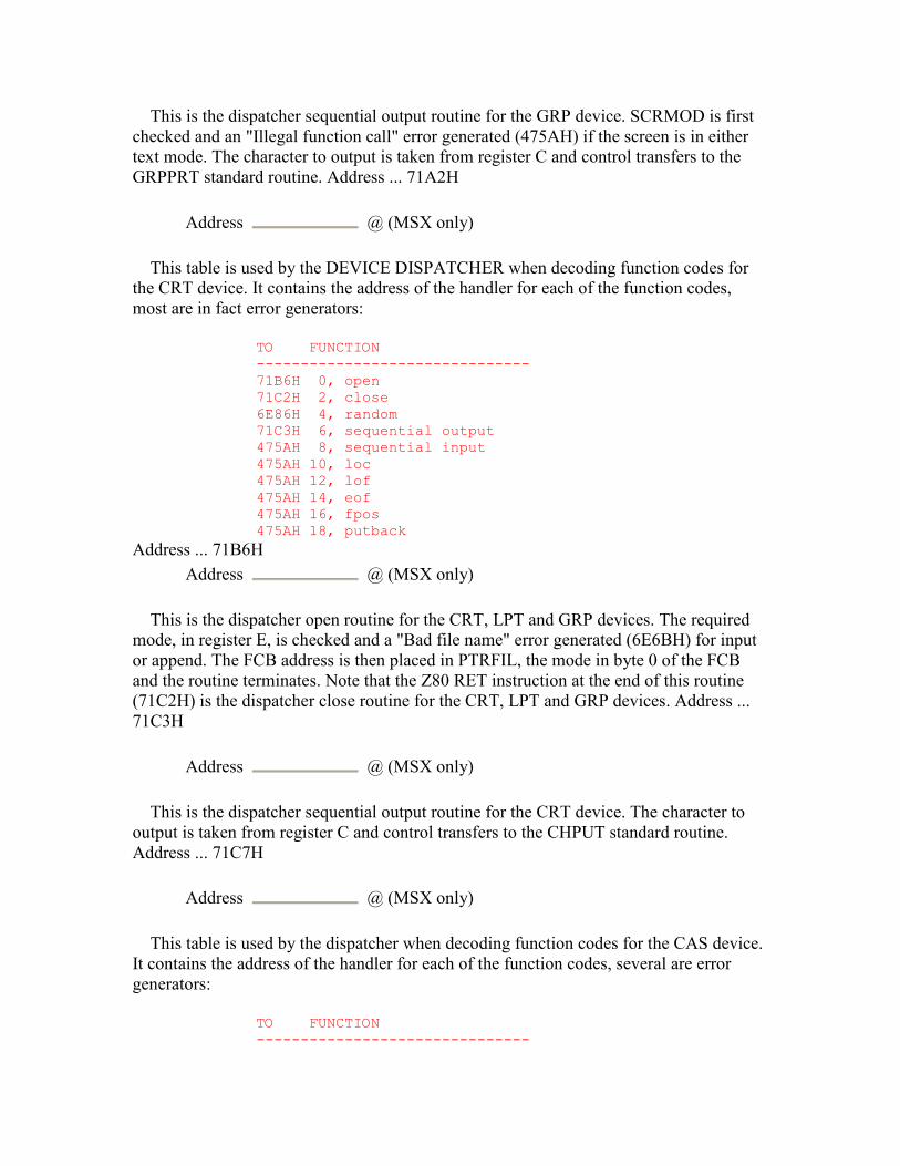
This is the dispatcher sequential output routine for the GRP device. SCRMOD is first checked and an "Illegal function call" error generated (475AH) if the screen is in either text mode. The character to output is taken from register C and control transfers to the GRPPRT standard routine. Address ... 71A2H
Address @ (MSX only)
This table is used by the DEVICE DISPATCHER when decoding function codes for the CRT device. It contains the address of the handler for each of the function codes, most are in fact error generators:
TO FUNCTION ------------------------------- 71B6H 0, open 71C2H 2, close 6E86H 4, random 71C3H 6, sequential output 475AH 8, sequential input 475AH 10, loc 475AH 12, lof 475AH 14, eof 475AH 16, fpos 475AH 18, putback
Address ... 71B6H Address @ (MSX only)
This is the dispatcher open routine for the CRT, LPT and GRP devices. The required mode, in register E, is checked and a "Bad file name" error generated (6E6BH) for input or append. The FCB address is then placed in PTRFIL, the mode in byte 0 of the FCB and the routine terminates. Note that the Z80 RET instruction at the end of this routine (71C2H) is the dispatcher close routine for the CRT, LPT and GRP devices. Address ... 71C3H
Address @ (MSX only)
This is the dispatcher sequential output routine for the CRT device. The character to output is taken from register C and control transfers to the CHPUT standard routine. Address ... 71C7H
Address @ (MSX only)
This table is used by the dispatcher when decoding function codes for the CAS device. It contains the address of the handler for each of the function codes, several are error generators:
TO FUNCTION -------------------------------
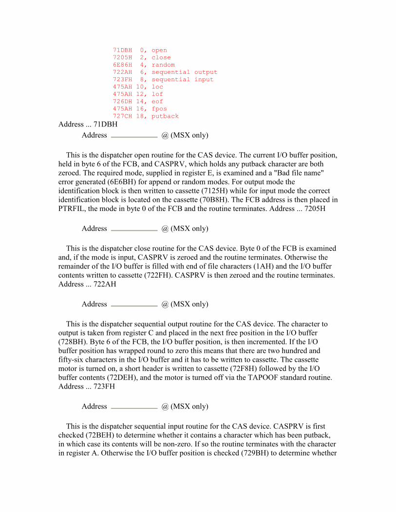
71DBH 0, open 7205H 2, close 6E86H 4, random 722AH 6, sequential output 723FH 8, sequential input 475AH 10, loc 475AH 12, lof 726DH 14, eof 475AH 16, fpos 727CH 18, putback
Address ... 71DBH Address @ (MSX only)
This is the dispatcher open routine for the CAS device. The current I/O buffer position, held in byte 6 of the FCB, and CASPRV, which holds any putback character are both zeroed. The required mode, supplied in register E, is examined and a "Bad file name" error generated (6E6BH) for append or random modes. For output mode the identification block is then written to cassette (7125H) while for input mode the correct identification block is located on the cassette (70B8H). The FCB address is then placed in PTRFIL, the mode in byte 0 of the FCB and the routine terminates. Address ... 7205H
Address @ (MSX only)
This is the dispatcher close routine for the CAS device. Byte 0 of the FCB is examined and, if the mode is input, CASPRV is zeroed and the routine terminates. Otherwise the remainder of the I/O buffer is filled with end of file characters (1AH) and the I/O buffer contents written to cassette (722FH). CASPRV is then zeroed and the routine terminates. Address ... 722AH
Address @ (MSX only)
This is the dispatcher sequential output routine for the CAS device. The character to output is taken from register C and placed in the next free position in the I/O buffer (728BH). Byte 6 of the FCB, the I/O buffer position, is then incremented. If the I/O buffer position has wrapped round to zero this means that there are two hundred and fifty-six characters in the I/O buffer and it has to be written to cassette. The cassette motor is turned on, a short header is written to cassette (72F8H) followed by the I/O buffer contents (72DEH), and the motor is turned off via the TAPOOF standard routine. Address ... 723FH
Address @ (MSX only)
This is the dispatcher sequential input routine for the CAS device. CASPRV is first checked (72BEH) to determine whether it contains a character which has been putback, in which case its contents will be non-zero. If so the routine terminates with the character in register A. Otherwise the I/O buffer position is checked (729BH) to determine whether
it contains any characters. If the I/O buffer is empty the cassette motor is turned on and the header located (72E9H). Two hundred and fifty-six characters are then read in (72D4H), the cassette motor turned off via the TAPION standard routine and the I/O buffer position reset to zero. The character is then taken from the current I/O buffer position and the position incremented. Finally the character is checked to see if it is the end of file character (1AH). If it is not the routine terminates with the character in register A and FLAG NC. Otherwise the end of file character is placed in CASPRV, so that succeeding sequential input requests will always return the end of file condition, and the routine terminates with FLAG C. - 184 - 5. ROM BASIC INTERPRETER Address ... 726DH
Address @ (MSX only)
This is the dispatcher eof routine for the CAS device. The next character is input (723FH) and placed in CASPRV. It is then tested for the end of file code (1AH) and the result placed in DAC as an integer, zero for false, FFFFH for true. Address ... 727CH
Address @ (MSX only)
This is the dispatcher putback routine for the CAS device. The character is simply placed in CASPRV to be picked up at the next sequential input request. Address ... 7281H
Address @ (MSX only)
This routine is used by the dispatcher close function to check if there are any characters in the I/O buffer and then zero the I/O buffer position byte in the FCB. Address ... 728BH
Address @ (MSX only)
This routine is used by the dispatcher sequential output function to place the character in register A in the I/O buffer at the current I/O buffer position, which is then incremented. Address ... 729BH
Address @ (MSX only)
This routine is used by the dispatcher sequential input function to collect the character at the current I/O buffer position, which is then incremented. Address ... 72A6H
Address @ (MSX only)
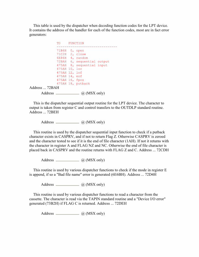
This table is used by the dispatcher when decoding function codes for the LPT device. It contains the address of the handler for each of the function codes, most are in fact error generators:
TO FUNCTION ------------------------------- 71B6H 0, open 71C2H 2, close 6E86H 4, random 72BAH 6, sequential output 475AH 8, sequential input 475AH 10, loc 475AH 12, lof 475AH 14, eof 475AH 16, fpos 475AH 18, putback
Address ... 72BAH Address @ (MSX only)
This is the dispatcher sequential output routine for the LPT device. The character to output is taken from register C and control transfers to the OUTDLP standard routine. Address ... 72BEH
Address @ (MSX only)
This routine is used by the dispatcher sequential input function to check if a putback character exists in CASPRV, and if not to return Flag Z. Otherwise CASPRV is zeroed and the character tested to see if it is the end of file character (1AH). If not it returns with the character in register A and FLAG NZ and NC. Otherwise the end of file character is placed back in CASPRV and the routine returns with FLAG Z and C. Address ... 72CDH
Address @ (MSX only)
This routine is used by various dispatcher functions to check if the mode in register E is append, if so a "Bad file name" error is generated (6E6BH). Address ... 72D4H
Address @ (MSX only)
This routine is used by various dispatcher functions to read a character from the cassette. The character is read via the TAPIN standard routine and a "Device I/O error" generated (73B2H) if FLAG C is returned. Address ... 72DEH
Address @ (MSX only)
This routine is used by various dispatcher functions to write a character to cassette. The character is written via the TAPOUT standard routine and a "Device I/O error" generated (73B2H) if FLAG C is returned. Address ... 72E9H
Address @ (MSX only)
This routine is used by various dispatcher functions to turn the cassette motor on for input. The motor is turned on via the TAPION standard routine and a "Device I/O error" generated (73B2H) if FLAG C is returned. Address ... 72F8H
Address @ (MSX only)
This routine is used by various dispatcher functions to turn the cassette motor on for output, control simply transfers to the TAPOON standard routine. Address ... 7304H
Address @ (MSX only)
This routine is used by the Interpreter Mainloop "OK" point, the "END" statement handler and the run-clear routine to shut down the printer. PRTFLG is first zeroed and then LPTPOS tested to see if any characters have been output but left hanging in the printer's line buffer. If so a CR,LF sequence is issued to flush the printer and LPTPOS zeroed. - 186 - 5. ROM BASIC INTERPRETER Address ... 7323H
Address @ (MSX only)
This routine issues a CR,LF sequence to the current output device via the OUTDO standard routine. LPTPOS or TTYPOS is then zeroed depending upon whether the printer or the screen is active. Address ... 7347H
Address @ (MSX only)
This routine is used by the Factor Evaluator to apply the "INKEY$" function. The state of the keyboard buffer is examined via the CHSNS standard routine. If the buffer is empty the address of a dummy null string descriptor is returned in DAC. Otherwise the next character is read from the keyboard buffer via the CHGET standard routine. After checking that sufficient space is available (6625H) the character is copied to the String Storage Area and the result descriptor created (6821H). Address ... 7367H
Address @ (MSX only)
This routine is used by the "LIST" statement handler to output a character to the current output device via the OUTDO standard routine. If the character is a LF code then a CR code is also issued. Address ... 7374H
Address @ (MSX only)
This routine is used by the Interpreter Mainloop to collect a line of text when input is from an I/O buffer rather than the keyboard, that is when a "LOAD" statement is active. Characters are sequentially input (6C71H) and placed in BUF until BUF fills up, a CR is detected or the end of file is reached. All characters are accepted apart from LF codes which are filtered out. If BUF fills up or a CR is detected the routine simply returns the line to the Mainloop. If the end of file is reached while some characters are in BUF the line is returned to the Mainloop. When end of file is reached with no characters in BUF then I/O buffer 0 is closed (6D7BH) and FILNAM checked to determine whether auto-run is required. If not control returns to the Interpreter "OK" point (411EH). Otherwise the system is cleared (629AH) and control transfers to the Runloop (NEWSTT, 4601H) to execute the program. Address ... 73B2H
Address @ (MSX only)
This is the "Device I/O error" generator. Address ... 73B7H
Address @ (MSX only)
This is the "MOTOR" statement handler. If no operand is present control transfers to the STMOTR standard routine with FFH in register A. If the "OFF" token (EBH) follows control transfers with 00H in register A. If the "ON" token (95H) follows control transfers with 01H in register A. - 187 - 5. ROM BASIC INTERPRETER Address ... 73CAH
Address @ (MSX only)
This is the "SOUND" statement handler. The register number operand, which must be less than fourteen, is evaluated (GETBYT, 521CH) and placed in register A. The data operand is evaluated (GETBYT, 521CH) and bit 7 set, bit 6 reset to avoid altering the PSG auxiliary I/O port modes. The data operand is placed in register E and control transfers to the WRTPSG standard routine. Address ... 73E4H
Address @ (MSX only)
This is a single ASCII space used by the "PLAY" statement handler to replace a null string operand with a one character blank string. Address ... 73E5H
Address @ (MSX only)
This is the "PLAY" statement handler. The address of the "PLAY" command table at 752EH is placed in MCLTAB for the macro language parser and PRSCNT zeroed. The first string operand, which is obligatory, is evaluated (4C64H), its storage freed
(FRESTR, 67D0H) and its length and address placed in VCBA at bytes 2, 3 and 4. The channel's stack pointer is initialized to VCBA+33 and placed in VCBA at bytes 5 and 6. If further text is present in the statement this process is repeated for voices B and C until a maximum of three operands have been evaluated, after this a "Syntax error" is generated (4055H). If there are less than three string operands present an end of queue mark (FFH) is placed in the queue (7507H) of each unused voice. Register A is then zeroed, to select voice A, and control drops into the play mainloop. Address ... 744DH
Address @ (MSX only)
This is the play mainloop. The number of free bytes in the current queue is checked (7521H) and, if less than eight bytes remain, the next voice is selected (74D6H) to avoid waiting for the queue to empty. The remaining length of the operand string is then taken from the current voice buffer and, if zero bytes remain to be parsed, the loop again skips to the next voice (74D6H). Otherwise the current string length and address are taken from the voice buffer and placed in MCLLEN and MCLPTR for the macro language parser. The old stack contents are copied from the voice buffer to the Z80 stack (6253H), MCLFLG is made non-zero and control transfers to the macro language parser (56A2H).
The macro language parser will normally scan along the string, using the "PLAY" statement command handlers, until the string is exhausted. However, if a music queue fills up during note generation an abnormal termination is forced back to the play mainloop (748EH) so that the next voice can be processed without waiting for the queue to empty. When control returns normally an end of queue mark is placed in the current queue (7507H) and PRSCNT is incremented to show the number of strings completed. If control returns abnormally then anything left on the Z80 stack is copied into the current voice buffer (6253H). Because of the recursive nature of the macro language parser where the "X" command is involved there may be a number of four byte string descriptors, marking the point where the original string was suspended, left on the Z80 stack at termination. Saving the stack contents in the voice buffer means they can be restored when the loop gets around to that voice again. Note that as there are only sixteen bytes available in each voice buffer an "Illegal function call" error is generated (475AH) if too much data remain on the stack. This will occur when a queue fills up and multiple, nested "X" commands exist, for example:
10 A$="XB$;" 20 B$="XC$;" 30 C$="XD$;" 40 D$=STRING$(150,"A") 50 PLAY A$
There seems to be a slight bug in this section as only fifteen bytes of stack data are allowed, instead of sixteen, before an error is generated.
When control returns from the macro language parser register A is incremented to select the next voice for processing. When all three voices have been processed INTFLG is checked and, if CTRL-STOP has been detected by the interrupt handler, control
transfers to the GICINI standard routine to halt all music and terminate. Assuming bit 7 of PRSCNT shows this to be the first pass through the mainloop, that is no voice has been temporarily suspended because of a full queue, PLYCNT is incremented and interrupt dequeueing started via the STRTMS standard routine. PRSCNT is then checked to determine the number of strings completed by the macro language parser. If all three operand strings have been completed the handler terminates, otherwise control transfers back to the start of the play mainloop to try each voice again. Address ... 7507H
Address @ (MSX only)
This routine is used by the "PLAY" statement handler to place an end of queue mark (FFH) in the current queue via the PUTQ standard routine. If the queue is full it waits until space becomes available. Address ... 7521H
Address @ (MSX only)
This routine is used by the "PLAY" statement handler to check how much space remains in the current queue via the LFTQ standard routine. If less than eight bytes remain (the largest possible music data packet is seven bytes long) FLAG C is returned. - 189 - 5. ROM BASIC INTERPRETER Address ... 752EH
Address @ (MSX only)
This table contains the valid command letters and associated addresses for the "PLAY" statement commands. Those commands which take a parameter, and consequently have bit 7 set in the table, are shown with an asterisk:
CMD TO ----------- A 763EH B 763EH C 763EH D 763EH E 763EH F 763EH G 763EH M* 759EH V* 7586H S* 75BEH N* 7621H O* 75EFH R* 75FCH T* 75E2H L* 75C8H X 5782H
Address ... 755FH Address @ (MSX only)
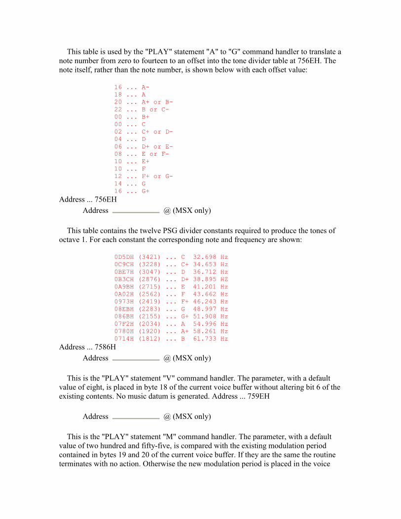
This table is used by the "PLAY" statement "A" to "G" command handler to translate a note number from zero to fourteen to an offset into the tone divider table at 756EH. The note itself, rather than the note number, is shown below with each offset value:
16 ... A- 18 ... A 20 ... A+ or B- 22 ... B or C- 00 ... B+ 00 ... C 02 ... C+ or D- 04 ... D 06 ... D+ or E- 08 ... E or F- 10 ... E+ 10 ... F 12 ... F+ or G- 14 ... G 16 ... G+
Address ... 756EH Address @ (MSX only)
This table contains the twelve PSG divider constants required to produce the tones of octave 1. For each constant the corresponding note and frequency are shown:
0D5DH (3421) ... C 32.698 Hz 0C9CH (3228) ... C+ 34.653 Hz 0BE7H (3047) ... D 36.712 Hz 0B3CH (2876) ... D+ 38.895 HZ 0A9BH (2715) ... E 41.201 Hz 0A02H (2562) ... F 43.662 Hz 0973H (2419) ... F+ 46.243 Hz 08EBH (2283) ... G 48.997 Hz 086BH (2155) ... G+ 51.908 Hz 07F2H (2034) ... A 54.996 Hz 0780H (1920) ... A+ 58.261 Hz 0714H (1812) ... B 61.733 Hz
Address ... 7586H Address @ (MSX only)
This is the "PLAY" statement "V" command handler. The parameter, with a default value of eight, is placed in byte 18 of the current voice buffer without altering bit 6 of the existing contents. No music datum is generated. Address ... 759EH
Address @ (MSX only)
This is the "PLAY" statement "M" command handler. The parameter, with a default value of two hundred and fifty-five, is compared with the existing modulation period contained in bytes 19 and 20 of the current voice buffer. If they are the same the routine terminates with no action. Otherwise the new modulation period is placed in the voice

buffer and bit 6 set in byte 18 of the voice buffer to indicate that the new value must be incorporated into the next music data packet produced. No music datum is generated. Address ... 75BEH
Address @ (MSX only)
This is the "PLAY" statement "S" command handler. The parameter is placed in byte 18 of the current voice buffer and bit 4 of the same byte set to indicate that the new value must be incorporated into the next music data packet produced. No music data is generated. Because of the PSG characteristics the shape and volume parameters are mutually exclusive so the same byte of the voice buffers is used for both. Address ... 75C8H
Address @ (MSX only)
This is the "PLAY" statement "L" command handler. The parameter, with a default value of four, is placed in byte 16 of the current voice buffer where it is used in the computation of succeeding note durations. No music datum is generated. Address ... 75E2H
Address @ (MSX only)
This is the "PLAY" statement "T" command handler. The parameter, with a default value of one hundred and twenty, is placed in byte 17 of the current voice buffer where it will be used in the computation of succeeding note durations. no music datum is generated. Address ... 75EFH
Address @ (MSX only)
This is the "PLAY" statement "O" command handler. The parameter, with a default value of four, is placed in byte 15 of the current voice buffer where it is used in the computation of succeeding note frequencies. No music datum is generated. Address ... 75FCH
Address @ (MSX only)
This is the "PLAY" statement "R" command handler. The length parameter, with a default value of four, is left in register pair DE and a zero tone divider value placed in register pair HL. The existing volume value is taken from byte 18 of the current voice buffer, temporarily replaced with a zero value and control transferred to the note generator (769CH). Address ... 7621H
Address @ (MSX only)
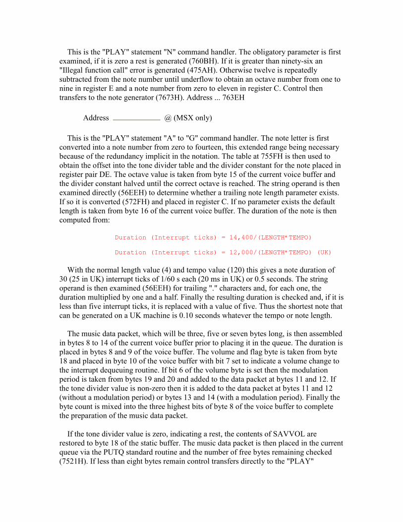
This is the "PLAY" statement "N" command handler. The obligatory parameter is first examined, if it is zero a rest is generated (760BH). If it is greater than ninety-six an "Illegal function call" error is generated (475AH). Otherwise twelve is repeatedly subtracted from the note number until underflow to obtain an octave number from one to nine in register E and a note number from zero to eleven in register C. Control then transfers to the note generator (7673H). Address ... 763EH
Address @ (MSX only)
This is the "PLAY" statement "A" to "G" command handler. The note letter is first converted into a note number from zero to fourteen, this extended range being necessary because of the redundancy implicit in the notation. The table at 755FH is then used to obtain the offset into the tone divider table and the divider constant for the note placed in register pair DE. The octave value is taken from byte 15 of the current voice buffer and the divider constant halved until the correct octave is reached. The string operand is then examined directly (56EEH) to determine whether a trailing note length parameter exists. If so it is converted (572FH) and placed in register C. If no parameter exists the default length is taken from byte 16 of the current voice buffer. The duration of the note is then computed from:
Duration (Interrupt ticks) = 14,400/(LENGTH*TEMPO) Duration (Interrupt ticks) = 12,000/(LENGTH*TEMPO) (UK)
With the normal length value (4) and tempo value (120) this gives a note duration of 30 (25 in UK) interrupt ticks of 1/60 s each (20 ms in UK) or 0.5 seconds. The string operand is then examined (56EEH) for trailing "." characters and, for each one, the duration multiplied by one and a half. Finally the resulting duration is checked and, if it is less than five interrupt ticks, it is replaced with a value of five. Thus the shortest note that can be generated on a UK machine is 0.10 seconds whatever the tempo or note length.
The music data packet, which will be three, five or seven bytes long, is then assembled in bytes 8 to 14 of the current voice buffer prior to placing it in the queue. The duration is placed in bytes 8 and 9 of the voice buffer. The volume and flag byte is taken from byte 18 and placed in byte 10 of the voice buffer with bit 7 set to indicate a volume change to the interrupt dequeuing routine. If bit 6 of the volume byte is set then the modulation period is taken from bytes 19 and 20 and added to the data packet at bytes 11 and 12. If the tone divider value is non-zero then it is added to the data packet at bytes 11 and 12 (without a modulation period) or bytes 13 and 14 (with a modulation period). Finally the byte count is mixed into the three highest bits of byte 8 of the voice buffer to complete the preparation of the music data packet.
If the tone divider value is zero, indicating a rest, the contents of SAVVOL are restored to byte 18 of the static buffer. The music data packet is then placed in the current queue via the PUTQ standard routine and the number of free bytes remaining checked (7521H). If less than eight bytes remain control transfers directly to the "PLAY"

statement handler (748EH), otherwise control returns normally to the macro language parser. Address ... 7754H
Address @ (MSX only)
This is the single precision constant 14,400 (12,000 in UK machines) used in the computation of note duration. The constant is inverted: first 2 bytes at 7756H and last 2 at 7754H (both MSB LSB). Address ... 7758H
Address @ (MSX only)
This is the "PUT" statement handler. Register B is set to 80H and control drops into the "GET" statement handler. Address ... 775BH
Address @ (MSX only)
This is the "GET" statement handler. Register B is zeroed, to distinguish "GET" from "PUT" and the next program token examined. Control then transfers to the "PUT SPRITE" statement handler (7AAFH) or the Disk BASIC "GET/PUT" statement handler (6C35H). Address ... 7766H
Address @ (MSX only)
This is the "LOCATE" statement handler. If a column coordinate is present it is evaluated (GETBYT, 521CH) and placed in register D, otherwise the current column is taken from CSRX. If a row coordinate is present it is evaluated (GETBYT, 521CH) and placed in register E, otherwise the current row is taken from CSRY. If a cursor switch operand exists it is evaluated (GETBYT, 521CH) and register A loaded with 78H for a zero operand (OFF) and 79H for any non-zero operand (ON). The cursor is then switched by outputting ESC, 78H/79H, "5" via the OUTDO standard routine. The row and column coordinates are placed in register pair HL and the cursor position set via the POSIT standard routine. Address ... 77A5H
Address @ (MSX only)
This is the "STOP ON/OFF/STOP" statement handler. The address of the device's TRPTBL status byte is placed in register pair HL and control transfers to the "ON/OFF/STOP" routine (77CFH). Address ... 77ABH
Address @ (MSX only)
This is the "SPRITE ON/OFF/STOP" statement handler. The address of the device's TRPTBL status byte is placed in register pair HL and control transfers to the "ON/OFF/STOP" routine (77CFH). Address ... 77B1H

Address @ (MSX only)
This is the "INTERVAL ON/OFF/STOP" statement handler. As there is no specific "INTERVAL" token (control transfers here when an "INT" token is found) a check is first made on the program text for the characters "E" and "R" then the "VAL" token (94H). The address of the device's TRPTBL status byte is placed in register pair HL and control transfers to the "ON/OFF/STOP" routine (77CFH). Address ... 77BFH
Address @ (MSX only)
This is the "STRIG ON/OFF/STOP" statement handler. The trigger number, from zero to four, is evaluated (7C08H) and the address of the device's TRPTBL status byte placed in register pair HL. The "ON/OFF/STOP" token is examined and the TRPTBL status byte modified accordingly (77FEH). Control then transfers directly to the Runloop (4612H) to avoid testing for pending interrupts until the end of the next statement. Address ... 77D4H
Address @ (MSX only)
This is the "KEY(n) ON/OFF/STOP" statement handler. The key number, from one to ten, is evaluated (GETBYT, 521CH) and the address of the device's TRPTBL status byte placed in register pair HL. The "ON/OFF/STOP" token is examined and the TRPTBL status byte modified accordingly (77FEH). Bit 0 of the TRPTBL status byte, the ON bit, is then copied into the corresponding entry in FNKFLG for use during the interrupt keyscan and control transfers directly to the Runloop (4612H). - 194 - 5. ROM BASIC INTERPRETER Address ... 77FEH
Address @ (MSX only)
This routine checks for the presence of one of the interrupt switching tokens and transfers control to the appropriate routine: "ON" (631BH), "OFF" (632BH) or "STOP" (6331H). If no token is present a "Syntax error" is generated (4055H). Address ... 7810H
Address @ (MSX only)
This routine is used by the "ON DEVICE GOSUB" statement handler (490DH) to check the program text for a device token. Unless none of the device tokens is present, in which case Flag C is returned, the device's TRPTBL entry number is returned in register B and the maximum allowable line number operand count in register C:
DEVICE TRPTBL# LINE NUMBERS ------------------------------------ KEY 00 10 STOP 10 01 SPRITE 11 01 STRIG 12 05
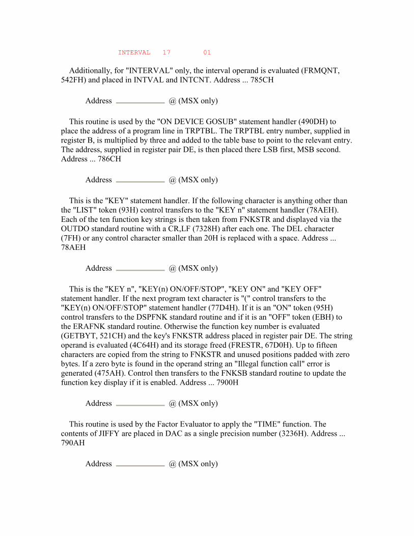
INTERVAL 17 01
Additionally, for "INTERVAL" only, the interval operand is evaluated (FRMQNT, 542FH) and placed in INTVAL and INTCNT. Address ... 785CH
Address @ (MSX only)
This routine is used by the "ON DEVICE GOSUB" statement handler (490DH) to place the address of a program line in TRPTBL. The TRPTBL entry number, supplied in register B, is multiplied by three and added to the table base to point to the relevant entry. The address, supplied in register pair DE, is then placed there LSB first, MSB second. Address ... 786CH
Address @ (MSX only)
This is the "KEY" statement handler. If the following character is anything other than the "LIST" token (93H) control transfers to the "KEY n" statement handler (78AEH). Each of the ten function key strings is then taken from FNKSTR and displayed via the OUTDO standard routine with a CR,LF (7328H) after each one. The DEL character (7FH) or any control character smaller than 20H is replaced with a space. Address ... 78AEH
Address @ (MSX only)
This is the "KEY n", "KEY(n) ON/OFF/STOP", "KEY ON" and "KEY OFF" statement handler. If the next program text character is "(" control transfers to the "KEY(n) ON/OFF/STOP" statement handler (77D4H). If it is an "ON" token (95H) control transfers to the DSPFNK standard routine and if it is an "OFF" token (EBH) to the ERAFNK standard routine. Otherwise the function key number is evaluated (GETBYT, 521CH) and the key's FNKSTR address placed in register pair DE. The string operand is evaluated (4C64H) and its storage freed (FRESTR, 67D0H). Up to fifteen characters are copied from the string to FNKSTR and unused positions padded with zero bytes. If a zero byte is found in the operand string an "Illegal function call" error is generated (475AH). Control then transfers to the FNKSB standard routine to update the function key display if it is enabled. Address ... 7900H
Address @ (MSX only)
This routine is used by the Factor Evaluator to apply the "TIME" function. The contents of JIFFY are placed in DAC as a single precision number (3236H). Address ... 790AH
Address @ (MSX only)
This routine is used by the Factor Evaluator to apply the "CSRLIN" function. The contents of CSRY are decremented and placed in DAC as an integer (2E9AH). Address ... 7911H
Address @ (MSX only)
This is the "TIME" statement handler. The operand is evaluated (FRMQNT, 542FH) and placed in JIFFY. Address ... 791BH
Address @ (MSX only)
This routine is used by the Factor Evaluator to apply the "PLAY" function. The numeric channel selection operand is evaluated (7C08H). If this is zero the contents of MUSICF are placed in DAC as an integer of value zero or FFFFH. Otherwise the channel number is used to select the appropriate bit of MUSICF and this is then converted to an integer as before. Address ... 7940H
Address @ (MSX only)
This routine is used by the Factor Evaluator to apply the "STICK" function to an operand contained in DAC. The stick number is checked (521FH) and passed to the GTSTCK standard routine in register A. The result is placed in DAC as an integer (4FCFH ) . Address ... 794CH
Address @ (MSX only)
This routine is used by the Factor Evaluator to apply the "STRIG" function to an operand contained in DAC. The trigger number is checked (521FH) and passed to the GTTRIG standard routine in register A. The result is placed in DAC as an integer of value zero or FFFFH. Address ... 795AH
Address @ (MSX only)
This routine is used by the Factor Evaluator to apply the "PDL" function to an operand contained in DAC. The paddle number is checked (521FH) and passed to the GTPDL standard routine in register A. The result is placed in DAC as an integer (4FCFH). Address ... 7969H
Address @ (MSX only)
This routine is used by the Factor Evaluator to apply the "PAD" function to an operand contained in DAC. The pad number is checked (521F) and passed to the GTPAD standard routine in register A. The result is placed in DAC as an integer for pads 1, 2, 5
or 6. For pads 0, 3, 4 or 7 the result is placed in DAC as an integer of value zero or FFFFH. Address ... 7980H
Address @ (MSX only)
This is the "COLOR" statement handler. If a foreground colour operand exists it is evaluated (GETBYT, 521CH) and placed in register E, otherwise the current foreground colour is taken from FORCLR. If a background colour operand exists it is evaluated (GETBYT, 521CH) and placed in register D, otherwise the current background colour is taken from BAKCLR. If a border colour operand exists it is evaluated (GETBYT, 521CH) and placed in BDRCLR. The foreground colour is placed in FORCLR and ATRBYT, the background colour in BAKCLR and control transfers to the CHGCLR standard routine to modify the VDP. Address ... 79CCH
Address @ (MSX only)
This is the "SCREEN" statement handler. If a mode operand exists it is evaluated (GETBYT, 521CH) and passed to the CHGMOD standard routine in register A. If a sprite size operand exists it is evaluated (GETBYT, 521CH) and placed in bits 0 and 1 of RG1SAV, the Workspace Area copy of VDP Mode Register 1. The VDP sprite parameters are then cleared via the CLRSPR standard routine. If a key click operand exists it is evaluated (GETBYT, 521CH) and placed in CLIKSW, zero to disable the click and non-zero to enable it. If a baud rate operand exists it is evaluated and the baud rate set (7A2DH). If a printer mode operand exists it is evaluated (GETBYT, 521CH) and placed in NTMSXP, zero for an MSX printer and non- zero for a general purpose printer. Address ... 7A2DH
Address @ (MSX only)
This routine is used to set the cassette baud rate. The operand is evaluated (GETBYT, 521CH) and five bytes copied from CS1200 or CS2400 to LOW as appropriate. Address ... 7A48H
Address @ (MSX only)
This is the "SPRITE" statement handler. If the next character is anything other than a "$" control transfers to the "SPRITE ON/OFF/STOP" statement handler (77ABH). SCRMOD is then checked and an "Illegal function call" error generated (475AH) if the screen is in 40x24 Text Mode. The sprite pattern number is evaluated and its location in the VRAM Sprite Pattern Table obtained (7AA0H). The string operand is then evaluated (4C5FH) and its storage freed (FRESTR, 67D0H). The sprite size, obtained via the GSPSIZ standard routine, is compared with the string length and, if the string is shorter than the sprite, the Sprite Pattern Table entry is first filled with zeroes via the FILVRM standard routine. Characters are then copied from the string body to the Sprite Pattern Table via the LDIRVM standard routine until the string is exhausted or the sprite is full.
If the string is longer than the sprite size any excess characters are ignored. Address ... 7A84H
Address @ (MSX only)
This routine is used by the Factor Evaluator to apply the "SPRITE$" function. The sprite pattern number is evaluated and its location in the VRAM Sprite Pattern Table obtained (7A9FH). The sprite size, obtained via the GSPSIZ standard routine, is then placed in register pair BC to control the number of bytes copied. After checking that sufficient space is available in the String Storage Area (6627H) the sprite pattern is copied from VRAM via the LDIRMV standard routine and the result descriptor created (6654H). Note that as no check is made on the screen mode during this function some interesting side effects can be found, see below. Address ... 7A9FH
Address @ (MSX only)
This routine is used by the "SPRITE$" statement and function to locate a sprite pattern in the VRAM Sprite Pattern Table. The pattern number operand is evaluated (7C08H) and passed to the CALPAT standard routine in register A. The pattern address is placed in register pair DE and the routine terminates.
Note that no check is made on the pattern number magnitude for differing sprite sizes. Pattern numbers up to two hundred and fifty-five are accepted even in 16x16 sprite mode when the maximum pattern number should be sixty-three. As a result VRAM addresses greater than 3FFFH will be produced which will wrap around into low VRAM. With the "SPRITE$" statement this will corrupt the Character Generator Table, for example:
10 SCREEN 3,2 20 SPRITE$(0)=STRING$(32,255) 30 PUT SPRITE 0,(0,0), ,0 40 SPRITE$(65)=STRING$(32,255) 50 GOTO 50
The above puts a real sprite in the top left of the screen and then uses an illegal statement in line 40 to corrupt the VRAM just to the right of it. The "SPRITE$" function can also be manipulated in this way and, as there is no screen mode check, up to thirty-two bytes of the Name Table can be read in 40x24 - 198 - 5. ROM BASIC INTERPRETER Text Mode, for example:
10 SCREEN 0,2 20 PRINT"something" 30 A$=SPRITE$(64) 40 PRINT A$
Address ... 7AAFH Address @ (MSX only)
This is the "GET/PUT SPRITE" statement handler, control is transferred here from the general "GET/PUT" statement handler (775BH). Register B is first checked to make sure that the statement is "PUT" and an "Illegal function call" error generated (475AH) if otherwise. SCRMOD is then checked and an "Illegal function call" error generated (475AH) if the screen is in 40x24 Text Mode. The sprite number operand, from zero to thirty-one, is evaluated (GETBYT, 521CH) and passed to the CALATR standard routine to locate the four byte attribute block in the Sprite Attribute Table. If a coordinate operand exists it is evaluated and the X coordinate placed in register pair BC, the Y coordinate in register pair DE (579CH).
The Y coordinate LSB is written to byte 0 of the attribute block in VRAM via the WRTVRM standard routine. Bit 7 of the X coordinate is then examined to determine whether it is negative, that is off the left hand side of the screen. If so thirty two is added to the X coordinate and register B is set to 80H to set the early clock bit in the attribute block. For example an X coordinate of -1 (FFFFH) would be changed to +31 with an early clock. The X coordinate LSB is then written to byte 1 of the attribute block via the WRTVRM standard routine. Byte 3 of the attribute block is read in via the RDVRM standard routine, the new early clock bit is mixed in and it is then written back to VRAM via the WRTVRM standard routine.
If a colour operand is present it is evaluated (GETBYT, 521CH), byte 3 of the attribute block is read in via the RDVRM standard routine the new colour code is mixed into the lowest four bits and it is written back to VRAM via the WRTVRM standard routine. If a pattern number operand exists it is evaluated (GETBYT, 521CH) and checked for magnitude against the current sprite size provided by the GSPSIZ standard routine. The maximum allowable pattern number is two hundred and fifty-five for 8x8 sprites and sixty- three for 16x16 sprites. The pattern number is written to byte 2 of the attribute block via the WRTVRM standard routine and the handler terminates. Address ... 7B37H
Address @ (MSX only)
This is the "VDP" statement handler. The register number operand, from zero to seven, is evaluated (7C08H) followed by the data operand (GETBYT, 521CH). The register number is placed in register C, the data value in register B and control transferred to the WRTVDP standard routine. - 199 - 5. ROM BASIC INTERPRETER Address ... 7B47H
Address @ (MSX only)
This routine is used by the Factor Evaluator to apply the "VDP" function. The register number operand, from zero to eight, is evaluated (7C08H) and added to RG0SAV to locate the corresponding register image in the Workspace Area. The VDP register image is then read and placed in DAC as an integer (4FCFH). Address ... 7B5AH
Address @ (MSX only)
This is the "BASE" statement handler. The VDP table number operand, from zero to nineteen, is evaluated (7C08H) followed by the base address operand (4C64H). After checking that the base address is less than 4000H (7BFEH) the VDP table number is used to locate the associated entry in the masking table at 7BA3H. The base address is ANDed with the mask and an "Illegal function call" error generated (475AH) if any illegal bits are set. The VDP table number is then added to TXTNAM to locate the current base address in the Workspace Area and the new base address placed there. The VDP table number is divided by five to determine which of the four screen modes the table belongs to. If this is the same as the current screen mode the new base address is also written to the VDP (7B99H). Address ... 7B99H
Address @ (MSX only)
This routine is used by the "BASE" statement handler to update the VDP base addresses. The current screen mode, in register A, is examined and control transfers to the SETTXT, SETT32, SETGRP or SETMLT standard routine as appropriate. Note that this is not a full VDP initialization and that the four current table addresses (NAMBAS, CGPBAS, PATBAS and ATRBAS) which are the ones actually used by the screen routines, are not updated. This can be demonstrated with the following, where the Interpreter carries on outputting to the old VRAM Name Table:
10 SCREEN 0 20 BASE(0)=&H400 30 PRINT"something" 40 FOR N=1 TO 2000:NEXT 50 BASE(0)=0
Note also that this routine contains a bug. While SETTXT is correctly used for 40x24 Text Mode, SETGRP is used for 32x24 Text Mode and SETMLT for Graphics Mode and Multicolour Mode. Any "BASE" statement should therefore be immediately followed by a "SCREEN" statement to perform a full initialization. Address ... 7BA3H
Address @ (MSX only)
This masking table is used by the "BASE" statement handler to ensure that only legal VDP base addresses are accepted. The table number and corresponding Workspace Area variable are shown with each mask:
MASK TABLE --------------------- 03FFH 00, TXTNAM 003FH 01, TXTCOL 07FFH 02, TXTCGP 007FH 03, TXTATR 07FFH 04, TXTPAT 03FFH 05, T32NAM 003FH 06, T32COL 07FFH 07, T32CGP
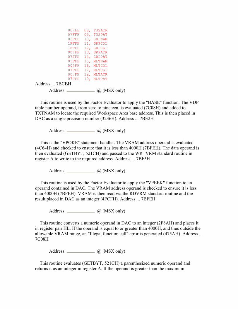
007FH 08, T32ATR 07FFH 09, T32PAT 03FFH 10, GRPNAM 1FFFH 11, GRPCOL 1FFFH 12, GRPCGP 007FH 13, GRPATR 07FFH 14, GRPPAT 03FFH 15, MLTNAM 003FH 16, MLTCOL 07FFH 17, MLTCGP 007FH 18, MLTATR 07FFH 19, MLTPAT
Address ... 7BCBH Address @ (MSX only)
This routine is used by the Factor Evaluator to apply the "BASE" function. The VDP table number operand, from zero to nineteen, is evaluated (7C08H) and added to TXTNAM to locate the required Workspace Area base address. This is then placed in DAC as a single precision number (3236H). Address ... 7BE2H
Address @ (MSX only)
This is the "VPOKE" statement handler. The VRAM address operand is evaluated (4C64H) and checked to ensure that it is less than 4000H (7BFEH). The data operand is then evaluated (GETBYT, 521CH) and passed to the WRTVRM standard routine in register A to write to the required address. Address ... 7BF5H
Address @ (MSX only)
This routine is used by the Factor Evaluator to apply the "VPEEK" function to an operand contained in DAC. The VRAM address operand is checked to ensure it is less than 4000H (7BFEH). VRAM is then read via the RDVRM standard routine and the result placed in DAC as an integer (4FCFH). Address ... 7BFEH
Address @ (MSX only)
This routine converts a numeric operand in DAC to an integer (2F8AH) and places it in register pair HL. If the operand is equal to or greater than 4000H, and thus outside the allowable VRAM range, an "Illegal function call" error is generated (475AH). Address ... 7C08H
Address @ (MSX only)
This routine evaluates (GETBYT, 521CH) a parenthesized numeric operand and returns it as an integer in register A. If the operand is greater than the maximum
allowable value initially supplied in register A an "Illegal function call" error is generated (475AH). Address ... 7C16H
Address @ (MSX only)
This is the "DSKO$" statement handler. An "Illegal function call" error is generated (475AH) on a standard MSX machine. Address ... 7C1BH
Address @ (MSX only)
This is the "SET" statement handler. An "Illegal function call" error is generated (475AH) on a standard MSX machine. Address ... 7C20H
Address @ (MSX only)
This is the "NAME" statement handler. An "Illegal function call" error is generated (475AH) on a standard MSX machine. Address ... 7C25H
Address @ (MSX only)
This is the "KILL" statement handler. An "Illegal function call" error is generated (475AH) on a standard MSX machine. Address ... 7C2AH
Address @ (MSX only)
This is the "IPL" statement handler. An "Illegal function call" error is generated (475AH) on a standard MSX machine. Address ... 7C2FH
Address @ (MSX only)
This is the "COPY" statement handler. An "Illegal function call" error is generated (475AH) on a standard MSX machine. Address ... 7C34H
Address @ (MSX only)
This is the "CMD" statement handler. An "Illegal function call" error is generated (475AH) on a standard MSX machine. Address ... 7C39H
Address @ (MSX only)
This routine is used by the Factor Evaluator to apply the "DSKF" function to an operand contained in DAC. An "Illegal function call" error is generated (475AH) on a standard MSX machine. - 202 - 5. ROM BASIC INTERPRETER Address ... 7C3EH
Address @ (MSX only)
This routine is used by the Factor Evaluator to apply the "DSKI$" function. An "Illegal function call" error is generated (475AH) on a standard MSX machine. Address ... 7C43H
Address @ (MSX only)
This routine is used by the Factor Evaluator to apply the "ATTR$" function. An "Illegal function call" error is generated (475AH) on a standard MSX machine. Address ... 7C48H
Address @ (MSX only)
This is the "LSET" statement handler. An "Illegal function call" error is generated (475AH) on a standard MSX machine. Address ... 7C4DH
Address @ (MSX only)
This is the "RSET" statement handler. An "Illegal function call" error is generated (475AH) on a standard MSX machine. Address ... 7C52H
Address @ (MSX only)
This is the "FIELD" statement handler. An "Illegal function call" error is generated (475AH) on a standard MSX machine. Address ... 7C57H
Address @ (MSX only)
This routine is used by the Factor Evaluator to apply the "MKI$" function to an operand contained in DAC. An "Illegal function call" error is generated (475AH) on a standard MSX machine. Address ... 7C5CH
Address @ (MSX only)
This routine is used by the Factor Evaluator to apply the "MKS$" function to an operand contained in DAC. An "Illegal function call" error is generated (475AH) on a standard MSX machine. Address ... 7C61H
Address @ (MSX only)

This routine is used by the Factor Evaluator to apply the "MKD$" function to an operand contained in DAC. An "Illegal function call" error is generated (475AH) on a standard MSX machine. Address ... 7C66H
Address @ (MSX only)
This routine is used by the Factor Evaluator to apply the "CVI" function to an operand contained in DAC. An "Illegal function call" error is generated (475AH) on a standard MSX machine. - 203 - 5. ROM BASIC INTERPRETER Address ... 7C6BH
Address @ (MSX only)
This routine is used by the Factor Evaluator to apply the "CVS" function to an operand contained in DAC. An "Illegal function call" error is generated (475AH) on a standard MSX machine. Address ... 7C70H
Address @ (MSX only)
This routine is used by the Factor Evaluator to apply the "CVD" function to an operand contained in DAC. An "Illegal function call" error is generated (475AH) on a standard MSX machine. Address ... 7C76H
Address @ (MSX only)
This routine completes the power-up initialization. At this point the entire Workspace Area is zeroed and only EXPTBL and SLTTBL have been initialized. A temporary stack is set at F376H and all one hundred and twelve hooks (560 bytes) filled with Z80 RET opcodes (C9H). HIMEM is set to F380H and the lowest RAM location found (7D5DH) and placed in BOTTOM. The one hundred and forty-four bytes of data commencing at 7F27H are copied to the Workspace Area from F380H to F40FH The function key strings are initialized via the INIFNK standard routine, end of BUF and NLONLY are zeroed and a comma is placed in BUFMIN and a colon in KBFMIN. The address of the MSX ROM character set is taken from locations 0004H and 0005H and placed in CGPNT+1 and PRMPRV is set to point to PRMSTK. Dummy values are placed in STKTOP, MEMSIZ and VARTAB (their correct values are not known yet), one I/O buffer is allocated (7E6BH) and the Z80 SP set (62E5H). A zero byte is placed at the base of RAM, TXTTAB is set to the following location and a "NEW" executed (6287H).
The VDP is then initialized via the INITIO, INIT32 and CLRSPR standard routines, the cursor coordinates are set to row 11, column 10 and the sign on message "MSX system etc." is displayed (6678H). After a three second delay a search is carried out for any extension ROMs (7D75H) and a further "NEW" executed (6287H) in case a BASIC program has been run from ROM.
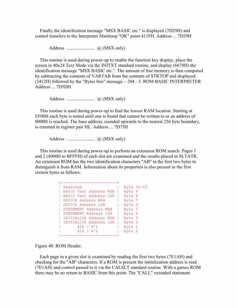
Finally the identification message "MSX BASIC etc." is displayed (7D29H) and control transfers to the Interpreter Mainloop "OK" point 411FH. Address ... 7D29H
Address @ (MSX only)
This routine is used during power-up to enable the function key display, place the screen in 40x24 Text Mode via the INITXT standard routine, and display (6678H) the identification message "MSX BASIC etc.". The amount of free memory is then computed by subtracting the contents of VARTAB from the contents of STKTOP and displayed (3412H) followed by the "Bytes free" message. - 204 - 5. ROM BASIC INTERPRETER Address ... 7D5DH
Address @ (MSX only)
This routine is used during power-up to find the lowest RAM location. Starting at EF00H each byte is tested until one is found that cannot be written to or an address of 8000H is reached. The base address, rounded upwards to the nearest 256 byte boundary, is returned in register pair HL. Address ... 7D75H
Address @ (MSX only)
This routine is used during power-up to perform an extension ROM search. Pages 1 and 2 (4000H to BFFFH) of each slot are examined and the results placed in SLTATR. An extension ROM has the two identification characters "AB" in the first two bytes to distinguish it from RAM. Information about its properties is also present in the first sixteen bytes as follows:
+------------------------+ | Reserved | Byte 10-15 | BASIC Text Address MSB | Byte 9 | BASIC Text Address LSB | Byte 8 | DEVICE Address MSB | Byte 7 | DEVICE Address LSB | Byte 6 | STATEMENT Address MSB | Byte 5 | STATEMENT Address LSB | Byte 4 | INITIALIZE Address MSB | Byte 3 | INITIALIZE Address LSB | Byte 2 | 42H (`B') | Byte 1 | 41H (`A') | Byte 0 +------------------------+
Figure 48: ROM Header.
Each page in a given slot is examined by reading the first two bytes (7E1AH) and checking for the "AB" characters. If a ROM is present the initialization address is read (7E1AH) and control passed to it via the CALSLT standard routine. With a games ROM there may be no return to BASIC from this point. The "CALL" extended statement

handler address is then read (7E1AH) and bit 5 of register B set if it is valid, that is non-zero. The extended device handler address is read (7E1AH) and bit 6 of register B set if it is valid. Finally the BASIC program text address is read (7E1AH) and bit 7 of register B set if it is valid. Register B is then copied to the relevant position in SLTATR and the search continued until no more slots remain.
SLTATR is then examined for any extension ROM flagged as containing BASIC program text. If one is found its position in SLTATR is converted to a Slot ID (7E2AH) and the ROM permanently switched in via the ENASLT standard routine. VARTAB is set to C000H, as it is not known how large the Program Text Area is, TXTTAB is set to 8008H and BASROM made non-zero to disable the CTRL-STOP key. The system is cleared (629AH) and control transfers to the Runloop (NEWSTT, 4601H) to execute the BASIC program. - 205 - 5. ROM BASIC INTERPRETER Address ... 7E1AH
Address @ (MSX only)
This routine is used to read two bytes from successive locations in an extension ROM. The initial address is supplied in register pair HL and the Slot ID in register C. The bytes are read via the RDSLT standard routine and returned in register pair DE. If both are zero FLAG Z is returned. Address ... 7E2AH
Address @ (MSX only)
This routine converts the SLTATR position supplied in register B into the corresponding Slot ID in register C and ROM base address in register H. The position is first modified so that it runs from 0 to 63 rather than from 64 to 1, so that the required information is present in the form:
7 6 5 4 3 2 1 0 +-----+-----+-----------+-----------+-----------+ | 0 | 0 | PSLOT # | SSLOT # | PAGE # | +-----+-----+-----------+-----------+-----------+
Figure 49.
Bits 0 and 1 are shifted into the highest two bits of register H to form the address. Bits 4 and 5 are shifted to bits 0 and 1 of register C to form the Primary Slot number. Bits 2 and 3 are shifted to bits 2 and 3 of register C to form the Secondary Slot number and bit 7 of the corresponding EXPTBL entry copied to bit 7 of register C. Address ... 7E4BH
Address @ (MSX only)
This is the "MAXFILES" statement handler. As control transfers here when a "MAX" token (CDH) is detected the program text is first checked for a trailing "FILES" token (B7H). The buffer count operand, from zero to fifteen, is then evaluated (GETBYT, 521CH) and any existing buffers closed (6C1CH). The required number of I/O buffers

are allocated (7E6BH), the system is cleared (62A7H) and control transfers directly to the Runloop (NEWSTT, 4601H). Address ... 7E6BH
Address @ (MSX only)
This is the I/O buffer allocation routine. It is used during power-up and by the "MAXFILES" and "CLEAR" statement handlers to allocate storage for the number of I/O buffers supplied in register A. Two hundred and sixty-seven bytes are subtracted from the contents of HIMEM for every buffer to produce a new MEMSIZ value. The size of the existing String Storage Area (initially two hundred bytes) is computed by subtracting the old contents of STKTOP from the old contents of MEMSIZ, this is then subtracted from the new MEMSIZ value to produce the new STKTOP value. A further one hundred and forty bytes are subtracted for the Z80 stack and an "Out of memory" error generated (6275H) if this address is lower than the start of the Variable Storage Area. Otherwise the buffer count is placed in MAXFIL and MEMSIZ and STKTOP set to their new values. The caller's return address is popped, the Z80 SP set to the new position and the return address pushed back onto the stack. FILTAB is then set to the start of the I/O buffer pointer block and each pointer set to point to the associated FCB. Finally the address of I/O buffer 0, the Interpreter's "LOAD" and "SAVE" buffer, is placed in NULBUF and the routine terminates. Address ... 7ED8H
Address @ (MSX only)
This is the plain text message "MSX system" terminated by a zero byte. Address ... 7EE4H
Address @ (MSX only)
This is the plain text message "version 1.0" CR,LF terminated by a zero byte. Address ... 7EF2H
Address @ (MSX only)
This is the plain text message "MSX BASIC " terminated by a zero byte. Address ... 7EFDH
Address @ (MSX only)
This is the plain text message "Copyright 1983 by Microsoft" CR,LF terminated by a zero byte. Address ... 7F1BH
Address @ (MSX only)
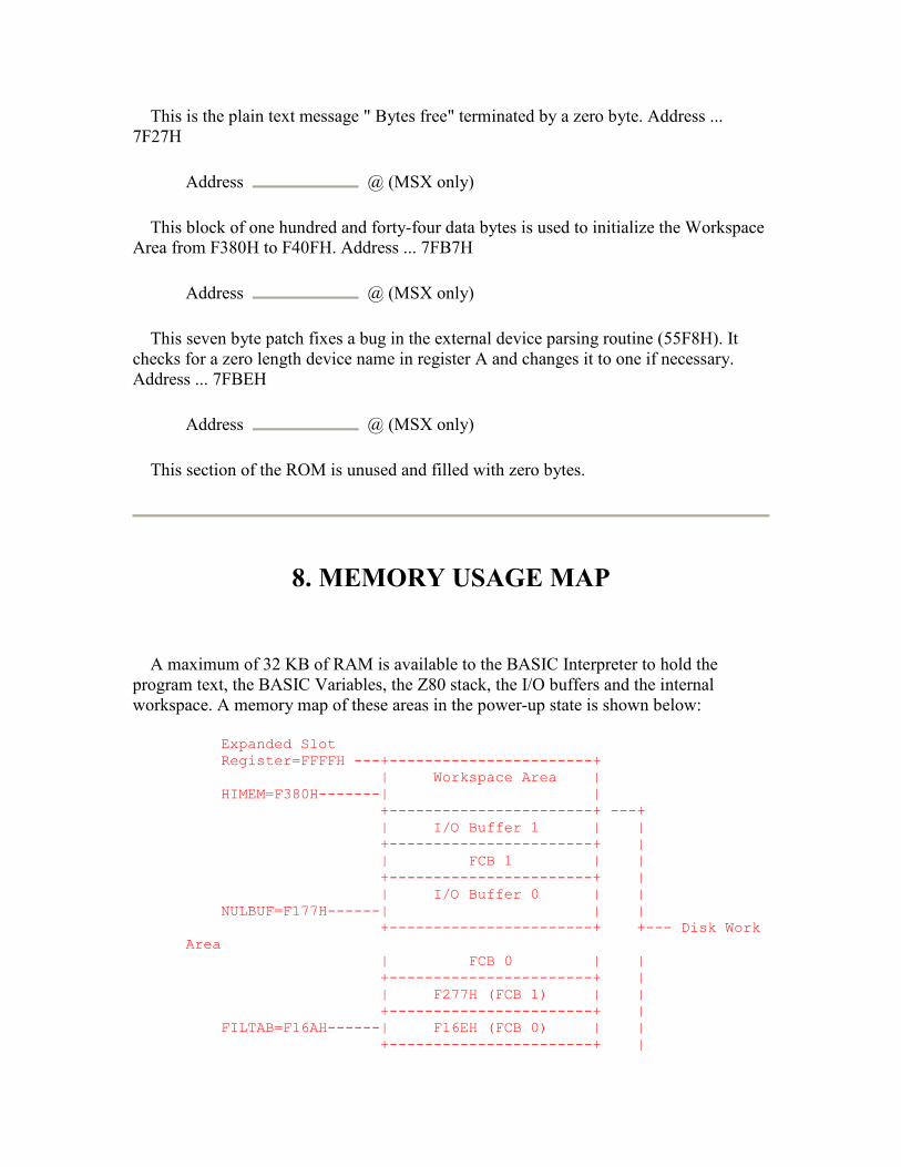
This is the plain text message " Bytes free" terminated by a zero byte. Address ... 7F27H
Address @ (MSX only)
This block of one hundred and forty-four data bytes is used to initialize the Workspace Area from F380H to F40FH. Address ... 7FB7H
Address @ (MSX only)
This seven byte patch fixes a bug in the external device parsing routine (55F8H). It checks for a zero length device name in register A and changes it to one if necessary. Address ... 7FBEH
Address @ (MSX only)
This section of the ROM is unused and filled with zero bytes.
8. MEMORY USAGE MAP
A maximum of 32 KB of RAM is available to the BASIC Interpreter to hold the program text, the BASIC Variables, the Z80 stack, the I/O buffers and the internal workspace. A memory map of these areas in the power-up state is shown below:
Expanded Slot Register=FFFFH ---+-----------------------+ | Workspace Area | HIMEM=F380H-------| | +-----------------------+ ---+ | I/O Buffer 1 | | +-----------------------+ | | FCB 1 | | +-----------------------+ | | I/O Buffer 0 | | NULBUF=F177H------| | | +-----------------------+ +--- Disk Work Area | FCB 0 | | +-----------------------+ | | F277H (FCB 1) | | +-----------------------+ | FILTAB=F16AH------| F16EH (FCB 0) | | +-----------------------+ |

| 00H | | +-----------------------+ ---+ MEMSIZ=F168H---+--| | | FRETOP=F168H---+ | String Storage Area | | | | | STKTOP=F0A0H------| | | +-----------------------+ | | Z80 Stack | | | | | +-----------------------+ | . . | STREND=8003H------. . | +-----------------------+ +--- User Work Area | Array Storage Area | | ARYTAB=8003H------| | | +-----------------------+ | | Variable Storage Area | | VARTAB=8003H------| | | +-----------------------+ | | Program Text Area | | | | | TXTTAB=8001H------+-----------------------+ | | 00H | | BOTTOM=8000H------+-----------------------+ ---+
Figure 50: Memory Usage Map 8000H to FFFFH.
The Program Text Area is composed of tokenized program lines stored in line number order and terminated by a zero end link, when in the "NEW" state only the end link is present. The zero byte at 8000H is a dummy end of line character needed to synchronize the Runloop at the start of a program. - 208 - 6. MEMORY MAP
The Variable and Array Storage Areas are composed of string or numeric Variables and Arrays stored in the order in which they are found in the program text. Execution speed improves marginally if Variables are declared before Arrays in a program as this reduces the amount of memory to be moved upwards.
The Z80 stack is positioned immediately below the String Storage Area, the structure of the stack top is shown below:
STKTOP-------| | +-----+ | 00H | Mainloop SP-------| 00H | +-----+ | 46H | Statement SP-------| 01H | +-----+
Figure 51: Z80 Stack Top.
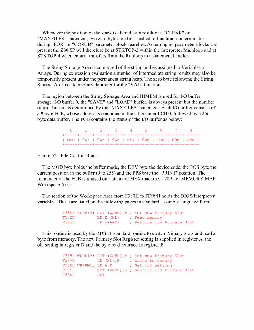
Whenever the position of the stack is altered, as a result of a "CLEAR" or "MAXFILES" statement, two zero bytes are first pushed to function as a terminator during "FOR" or "GOSUB" parameter block searches. Assuming no parameter blocks are present the Z80 SP will therefore be at STKTOP-2 within the Interpreter Mainloop and at STKTOP-4 when control transfers from the Runloop to a statement handler.
The String Storage Area is composed of the string bodies assigned to Variables or Arrays. During expression evaluation a number of intermediate string results may also be temporarily present under the permanent string heap. The zero byte following the String Storage Area is a temporary delimiter for the "VAL" function.
The region between the String Storage Area and HIMEM is used for I/O buffer storage. I/O buffer 0, the "SAVE" and "LOAD" buffer, is always present but the number of user buffers is determined by the "MAXFILES" statement. Each I/O buffer consists of a 9 byte FCB, whose address is contained in the table under FCB 0, followed by a 256 byte data buffer. The FCB contains the status of the I/O buffer as below:
0 1 2 3 4 5 6 7 8 +-----+-----+-----+-----+-----+-----+-----+-----+-----+ | Mod | 00H | 00H | 00H | DEV | 00H | POS | 00H | PPS | +-----+-----+-----+-----+-----+-----+-----+-----+-----+
Figure 52 : File Control Block.
The MOD byte holds the buffer mode, the DEV byte the device code, the POS byte the current position in the buffer (0 to 255) and the PPS byte the "PRINT" position. The remainder of the FCB is unused on a standard MSX machine. - 209 - 6. MEMORY MAP Workspace Area
The section of the Workspace Area from F380H to FD99H holds the BIOS/Interpreter variables. These are listed on the following pages in standard assembly language form:
F380H RDPRIM: OUT (0A8H),A ; Set new Primary Slot F382H LD E,(HL) ; Read memory F383H JR WRPRM1 ; Restore old Primary Slot
This routine is used by the RDSLT standard routine to switch Primary Slots and read a byte from memory. The new Primary Slot Register setting is supplied in register A, the old setting in register D and the byte read returned in register E.
F385H WRPRIM: OUT (0A8H),A ; Set new Primary Slot F387H LD (HL),E ; Write to memory F388H WRPRM1: LD A,D ; Get old setting F389H OUT (0A8H),A ; Restore old Primary Slot F38BH RET

This routine is used by the WRSLT standard routine to switch Primary Slots and write a byte to memory. The new Primary Slot Register setting is supplied in register A, the old setting in register D and the byte to write in register E.
F38CH CLPRIM: OUT (0A8H),A ; Set new Primary Slot F38EH EX AF,AF' ; Swap to AF for call F38FH CALL CLPRM1 ; Do it F392H EX AF,AF' ; Swap to AF F393H POP AF ; Get old setting F394H OUT (0A8H),A ; Restore old Primary Slot F396H EX AF,AF' ; Swap to AF F397H RET F398H CLPRM1: JP (IX)
This routine is used by the CALSLT standard routine to switch Primary Slots and call an address. The new Primary Slot Register setting is supplied in register A, the old setting on the Z80 stack and the address to call in register pair IX.
F39AH USRTAB: DEFW 475AH ; USR 0 F39CH DEFW 475AH ; USR 1 F39EH DEFW 475AH ; USR 2 F3A0H DEFW 475AH ; USR 3 F3A2H DEFW 475AH ; USR 4 F3A4H DEFW 475AH ; USR 5 F3A6H DEFW 475AH ; USR 6 F3A8H DEFW 475AH ; USR 7 F3AAH DEFW 475AH ; USR 8 F3ACH DEFW 475AH ; USR 9
These ten variables contain the "USR" function addresses. Their values are set to the Interpreter "Illegal function call" error generator at power-up and thereafter only altered by the "DEFUSR" statement. F3AEH LINL40: DEFB 39 ; 39 in Japanese MSX, 37 in European.
This variable contains the 40x24 Text Mode screen width. Its value is set at power-up and thereafter only altered by the "WIDTH" statement. F3AFH LINL32: DEFB 29
This variable contains the 32x24 Text Mode screen width. Its value is set at power-up and thereafter only altered by the "WIDTH" statement. F3B0H LINLEN: DEFB 39 ; 39 in Japanese MSX, 37 in European.
This variable contains the current text mode screen width. Its value is set from LINL40 or LINL32 whenever the VDP is initialized to a text mode via the INITXT or INIT32 standard routines. F3B1H CRTCNT: DEFB 24
This variable contains the number of rows on the screen. Its value is set at power-up and thereafter unaltered. F3B2H CLMLST: DEFB 14
This variable contains the minimum number of columns that must still be available on a line for a data item to be "PRINT"ed, if less space is available a CR,LF is issued first.
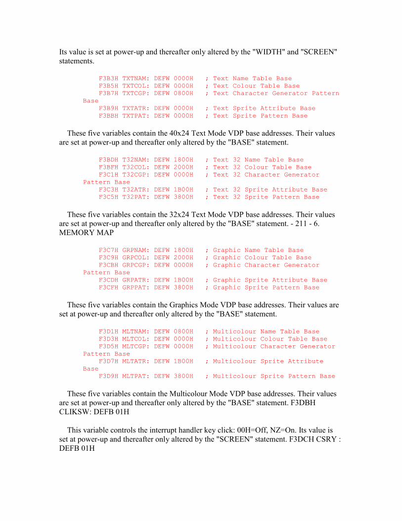
Its value is set at power-up and thereafter only altered by the "WIDTH" and "SCREEN" statements.
F3B3H TXTNAM: DEFW 0000H ; Text Name Table Base F3B5H TXTCOL: DEFW 0000H ; Text Colour Table Base F3B7H TXTCGP: DEFW 0800H ; Text Character Generator Pattern Base F3B9H TXTATR: DEFW 0000H ; Text Sprite Attribute Base F3BBH TXTPAT: DEFW 0000H ; Text Sprite Pattern Base
These five variables contain the 40x24 Text Mode VDP base addresses. Their values are set at power-up and thereafter only altered by the "BASE" statement.
F3BDH T32NAM: DEFW 1800H ; Text 32 Name Table Base F3BFH T32COL: DEFW 2000H ; Text 32 Colour Table Base F3C1H T32CGP: DEFW 0000H ; Text 32 Character Generator Pattern Base F3C3H T32ATR: DEFW 1B00H ; Text 32 Sprite Attribute Base F3C5H T32PAT: DEFW 3800H ; Text 32 Sprite Pattern Base
These five variables contain the 32x24 Text Mode VDP base addresses. Their values are set at power-up and thereafter only altered by the "BASE" statement. - 211 - 6. MEMORY MAP
F3C7H GRPNAM: DEFW 1800H ; Graphic Name Table Base F3C9H GRPCOL: DEFW 2000H ; Graphic Colour Table Base F3CBH GRPCGP: DEFW 0000H ; Graphic Character Generator Pattern Base F3CDH GRPATR: DEFW 1B00H ; Graphic Sprite Attribute Base F3CFH GRPPAT: DEFW 3800H ; Graphic Sprite Pattern Base
These five variables contain the Graphics Mode VDP base addresses. Their values are set at power-up and thereafter only altered by the "BASE" statement.
F3D1H MLTNAM: DEFW 0800H ; Multicolour Name Table Base F3D3H MLTCOL: DEFW 0000H ; Multicolour Colour Table Base F3D5H MLTCGP: DEFW 0000H ; Multicolour Character Generator Pattern Base F3D7H MLTATR: DEFW 1B00H ; Multicolour Sprite Attribute Base F3D9H MLTPAT: DEFW 3800H ; Multicolour Sprite Pattern Base
These five variables contain the Multicolour Mode VDP base addresses. Their values are set at power-up and thereafter only altered by the "BASE" statement. F3DBH CLIKSW: DEFB 01H
This variable controls the interrupt handler key click: 00H=Off, NZ=On. Its value is set at power-up and thereafter only altered by the "SCREEN" statement. F3DCH CSRY : DEFB 01H
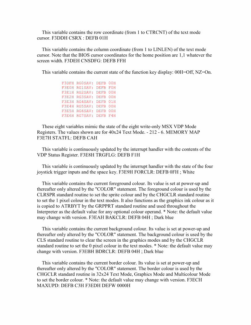
This variable contains the row coordinate (from 1 to CTRCNT) of the text mode cursor. F3DDH CSRX : DEFB 01H
This variable contains the column coordinate (from 1 to LINLEN) of the text mode cursor. Note that the BIOS cursor coordinates for the home position are 1,1 whatever the screen width. F3DEH CNSDFG: DEFB FFH
This variable contains the current state of the function key display: 00H=Off, NZ=On.
F3DFH RG0SAV: DEFB 00H F3E0H RG1SAV: DEFB F0H F3E1H RG2SAV: DEFB 00H F3E2H RG3SAV: DEFB 00H F3E3H RG4SAV: DEFB 01H F3E4H RG5SAV: DEFB 00H F3E5H RG6SAV: DEFB 00H F3E6H RG7SAV: DEFB F4H
These eight variables mimic the state of the eight write-only MSX VDP Mode Registers. The values shown are for 40x24 Text Mode. - 212 - 6. MEMORY MAP F3E7H STATFL: DEFB CAH
This variable is continuously updated by the interrupt handler with the contents of the VDP Status Register. F3E8H TRGFLG: DEFB F1H
This variable is continuously updated by the interrupt handler with the state of the four joystick trigger inputs and the space key. F3E9H FORCLR: DEFB 0FH ; White
This variable contains the current foreground colour. Its value is set at power-up and thereafter only altered by the "COLOR" statement. The foreground colour is used by the CLRSPR standard routine to set the sprite colour and by the CHGCLR standard routine to set the 1 pixel colour in the text modes. It also functions as the graphics ink colour as it is copied to ATRBYT by the GRPPRT standard routine and used throughout the Interpreter as the default value for any optional colour operand. * Note: the default value may change with version. F3EAH BAKCLR: DEFB 04H ; Dark blue
This variable contains the current background colour. Its value is set at power-up and thereafter only altered by the "COLOR" statement. The background colour is used by the CLS standard routine to clear the screen in the graphics modes and by the CHGCLR standard routine to set the 0 pixel colour in the text modes. * Note: the default value may change with version. F3EBH BDRCLR: DEFB 04H ; Dark blue
This variable contains the current border colour. Its value is set at power-up and thereafter only altered by the "COLOR" statement. The border colour is used by the CHGCLR standard routine in 32x24 Text Mode, Graphics Mode and Multicolour Mode to set the border colour. * Note: the default value may change with version. F3ECH MAXUPD: DEFB C3H F3EDH DEFW 0000H

These two bytes are filled in by the "LINE" statement handler to form a Z80 JP to the RIGHTC, LEFTC, UPC or DOWNC standard routines. F3EFH MINUPD: DEFB C3H F3F0H DEFW 0000H
These two bytes are filled in by the "LINE" statement handler to form a Z80 JP to the RIGHTC, LEFTC, UPC or DOWNC standard routines. - 213 - 6. MEMORY MAP F3F2H ATRBYT: DEFB 0FH
This variable contains the graphics ink colour used by the SETC and NSETCX standard routines. F3F3H QUEUES: DEFW F959H
This variable contains the address of the control blocks for the three music queues. Its value is set at power-up and thereafter unaltered. F3F5H FRCNEW: DEFB FFH
This variable contains a flag to distinguish the two statements in the "CLOAD/CLOAD?" statement handler: 00H=CLOAD, FFH=CLOAD?. F3F6H SCNCNT: DEFB 01H
This variable is used as a counter by the interrupt handler to control the rate at which keyboard scans are performed. F3F7H REPCNT: DEFB 01H
This variable is used as a counter by the interrupt handler to control the key repeat rate. F3F8H PUTPNT: DEFW FBF0H
This variable contains the address of the put position in KEYBUF. F3FAH GETPNT: DEFW FBF0H
This variable contains the address of the get position in KEYBUF.
F3FCH CS1200: DEFB 53H ; LO cycle 1st half F3FDH DEFB 5CH ; LO cycle 2nd half F3FEH DEFB 26H ; HI cycle 1st half F3FFH DEFB 2DH ; HI cycle 2nd half F400H DEFB 0FH ; Header cycle count
These five variables contain the 1200 baud cassette parameters. Their values are set at power-up and thereafter unaltered.
F401H CS2400: DEFB 25H ; LO cycle 1st half F402H DEFB 2DH ; LO cycle 2nd half F403H DEFB 0EH ; HI cycle 1st half F404H DEFB 16H ; HI cycle 2nd half F405H DEFB 1FH ; Header cycle count
These five variables contain the 2400 baud cassette parameters. Their values are set at power-up and thereafter unaltered. - 214 - 6. MEMORY MAP
F406H LOW : DEFB 53H ; LO cycle 1st half
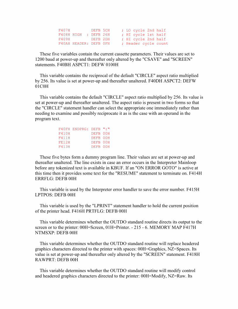
F407H DEFB 5CH ; LO cycle 2nd half F408H HIGH : DEFB 26H ; HI cycle 1st half F409H DEFB 2DH ; HI cycle 2nd half F40AH HEADER: DEFB 0FH ; Header cycle count
These five variables contain the current cassette parameters. Their values are set to 1200 baud at power-up and thereafter only altered by the "CSAVE" and "SCREEN" statements. F40BH ASPCT1: DEFW 0100H
This variable contains the reciprocal of the default "CIRCLE" aspect ratio multiplied by 256. Its value is set at power-up and thereafter unaltered. F40DH ASPCT2: DEFW 01C0H
This variable contains the default "CIRCLE" aspect ratio multiplied by 256. Its value is set at power-up and thereafter unaltered. The aspect ratio is present in two forms so that the "CIRCLE" statement handler can select the appropriate one immediately rather than needing to examine and possibly reciprocate it as is the case with an operand in the program text.
F40FH ENDPRG: DEFB ":" F410H DEFB 00H F411H DEFB 00H FE12H DEFB 00H F413H DEFB 00H
These five bytes form a dummy program line. Their values are set at power-up and thereafter unaltered. The line exists in case an error occurs in the Interpreter Mainloop before any tokenized text is available in KBUF. If an "ON ERROR GOTO" is active at this time then it provides some text for the "RESUME" statement to terminate on. F414H ERRFLG: DEFB 00H
This variable is used by the Interpreter error handler to save the error number. F415H LPTPOS: DEFB 00H
This variable is used by the "LPRINT" statement handler to hold the current position of the printer head. F416H PRTFLG: DEFB 00H
This variable determines whether the OUTDO standard routine directs its output to the screen or to the printer: 00H=Screen, 01H=Printer. - 215 - 6. MEMORY MAP F417H NTMSXP: DEFB 00H
This variable determines whether the OUTDO standard routine will replace headered graphics characters directed to the printer with spaces: 00H=Graphics, NZ=Spaces. Its value is set at power-up and thereafter only altered by the "SCREEN" statement. F418H RAWPRT: DEFB 00H
This variable determines whether the OUTDO standard routine will modify control and headered graphics characters directed to the printer: 00H=Modify, NZ=Raw. Its

value is set at power- up and thereafter unaltered. F419H VLZADR: DEFW 0000H F41BH VLZDAT: DEFB 00H
These variables contain the address and value of any character temporarily removed by the "VAL" function. F41CH CURLIN: DEFW FFFFH
This variable contains the current Interpreter line number. A value of FFFFH denotes direct mode. F41EH KBFMIN: DEFB ":"
This byte provides a dummy prefix to the tokenized text contained in KBUF. Its function is similar to that of ENDPRG but is used for the situation where an error occurs within a direct statement. F41FH KBUF : DEFS 318
This buffer contains the tokenized form of the input line collected by the Interpreter Mainloop. When a direct statement is executed the contents of this buffer form the program text. F55DH BUFMIN: DEFB ","
This byte provides a dummy prefix to the text contained in BUF. It is used to synchronize the "INPUT" statement handler as it starts to analyze the input text. F55EH BUF : DEFS 259
This buffer contains the text collected from the console by the INLIN standard routine. F661H TTYPOS: DEFB 00H
This variable is used by the "PRINT" statement handler to hold the current screen position (Teletype!). - 216 - 6. MEMORY MAP F662H DIMFLG: DEFB 00H
This variable is normally zero but is set by the "DIM" statement handler to control the operation of the variable search routine. F663H VALTYP: DEFB 02H
This variable contains the type code of the operand currently contained in DAC: 2=integer, 3=String, 4=Single Precision, 8=Double Precision. F664H DORES : DEFB 00H
This variable is normally zero but is set to prevent the tokenization of unquoted keywords following a "DATA" token. F665H DONUM : DEFB 00H
This variable is normally zero but is set when a numeric constant follows one of the keywords GOTO, GOSUB, THEN, etc., and must be tokenized to the special line number operand form. F666H CONTXT: DEFW 0000H
This variable is used by the CHRGTR standard routine to save the address of the character following a numeric constant in the program text. F668H CONSAV: DEFB 00H
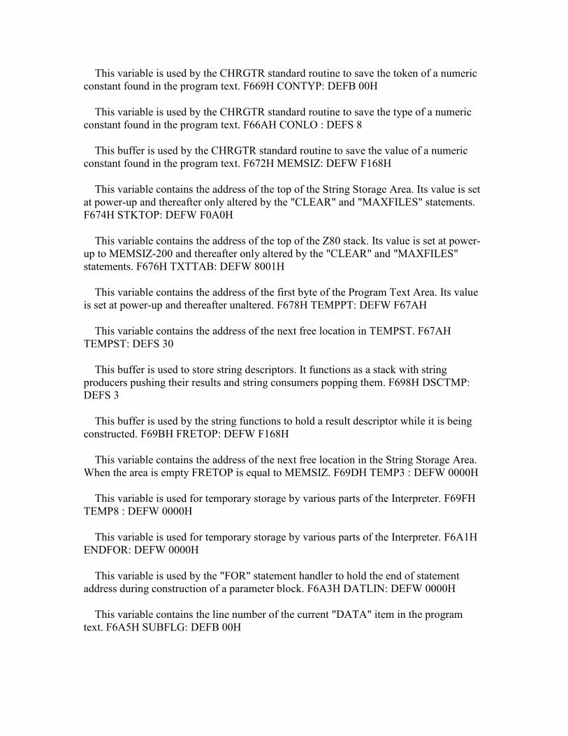
This variable is used by the CHRGTR standard routine to save the token of a numeric constant found in the program text. F669H CONTYP: DEFB 00H
This variable is used by the CHRGTR standard routine to save the type of a numeric constant found in the program text. F66AH CONLO : DEFS 8
This buffer is used by the CHRGTR standard routine to save the value of a numeric constant found in the program text. F672H MEMSIZ: DEFW F168H
This variable contains the address of the top of the String Storage Area. Its value is set at power-up and thereafter only altered by the "CLEAR" and "MAXFILES" statements. F674H STKTOP: DEFW F0A0H
This variable contains the address of the top of the Z80 stack. Its value is set at power-up to MEMSIZ-200 and thereafter only altered by the "CLEAR" and "MAXFILES" statements. F676H TXTTAB: DEFW 8001H
This variable contains the address of the first byte of the Program Text Area. Its value is set at power-up and thereafter unaltered. F678H TEMPPT: DEFW F67AH
This variable contains the address of the next free location in TEMPST. F67AH TEMPST: DEFS 30
This buffer is used to store string descriptors. It functions as a stack with string producers pushing their results and string consumers popping them. F698H DSCTMP: DEFS 3
This buffer is used by the string functions to hold a result descriptor while it is being constructed. F69BH FRETOP: DEFW F168H
This variable contains the address of the next free location in the String Storage Area. When the area is empty FRETOP is equal to MEMSIZ. F69DH TEMP3 : DEFW 0000H
This variable is used for temporary storage by various parts of the Interpreter. F69FH TEMP8 : DEFW 0000H
This variable is used for temporary storage by various parts of the Interpreter. F6A1H ENDFOR: DEFW 0000H
This variable is used by the "FOR" statement handler to hold the end of statement address during construction of a parameter block. F6A3H DATLIN: DEFW 0000H
This variable contains the line number of the current "DATA" item in the program text. F6A5H SUBFLG: DEFB 00H
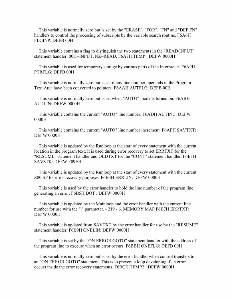
This variable is normally zero but is set by the "ERASE", "FOR", "FN" and "DEF FN" handlers to control the processing of subscripts by the variable search routine. F6A6H FLGINP: DEFB 00H
This variable contains a flag to distinguish the two statements in the "READ/INPUT" statement handler: 00H=INPUT, NZ=READ. F6A7H TEMP : DEFW 0000H
This variable is used for temporary storage by various parts of the Interpreter. F6A9H PTRFLG: DEFB 00H
This variable is normally zero but is set if any line number operands in the Program Text Area have been converted to pointers. F6AAH AUTFLG: DEFB 00H
This variable is normally zero but is set when "AUTO" mode is turned on. F6ABH AUTLIN: DEFW 0000H
This variable contains the current "AUTO" line number. F6ADH AUTINC: DEFW 0000H
This variable contains the current "AUTO" line number increment. F6AFH SAVTXT: DEFW 0000H
This variable is updated by the Runloop at the start of every statement with the current location in the program text. It is used during error recovery to set ERRTXT for the "RESUME" statement handler and OLDTXT for the "CONT" statement handler. F6B1H SAVSTK: DEFW F09EH
This variable is updated by the Runloop at the start of every statement with the current Z80 SP for error recovery purposes. F6B3H ERRLIN: DEFW 0000H
This variable is used by the error handler to hold the line number of the program line generating an error. F6B5H DOT : DEFW 0000H
This variable is updated by the Mainloop and the error handler with the current line number for use with the "." parameter. - 219 - 6. MEMORY MAP F6B7H ERRTXT: DEFW 0000H
This variable is updated from SAVTXT by the error handler for use by the "RESUME" statement handler. F6B9H ONELIN: DEFW 0000H
This variable is set by the "ON ERROR GOTO" statement handler with the address of the program line to execute when an error occurs. F6BBH ONEFLG: DEFB 00H
This variable is normally zero but is set by the error handler when control transfers to an "ON ERROR GOTO" statement. This is to prevent a loop developing if an error occurs inside the error recovery statements. F6BCH TEMP2 : DEFW 0000H
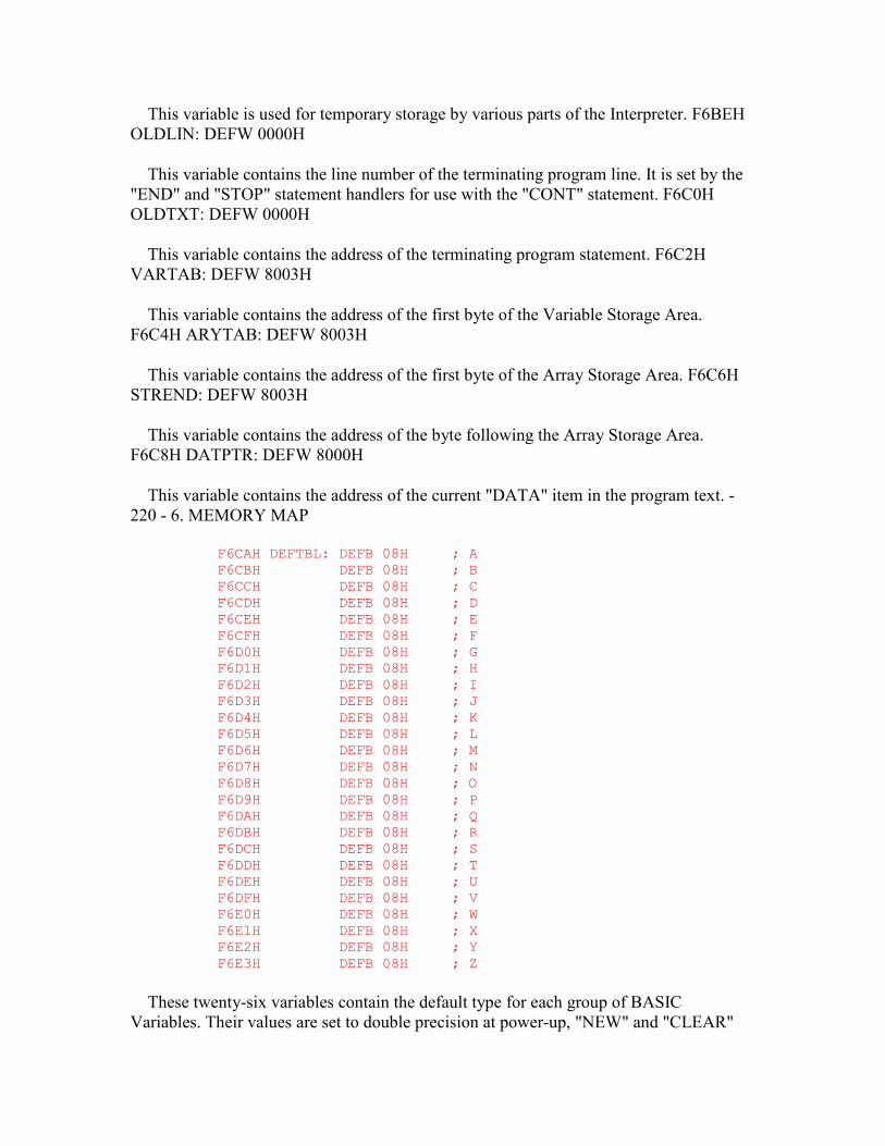
This variable is used for temporary storage by various parts of the Interpreter. F6BEH OLDLIN: DEFW 0000H
This variable contains the line number of the terminating program line. It is set by the "END" and "STOP" statement handlers for use with the "CONT" statement. F6C0H OLDTXT: DEFW 0000H
This variable contains the address of the terminating program statement. F6C2H VARTAB: DEFW 8003H
This variable contains the address of the first byte of the Variable Storage Area. F6C4H ARYTAB: DEFW 8003H
This variable contains the address of the first byte of the Array Storage Area. F6C6H STREND: DEFW 8003H
This variable contains the address of the byte following the Array Storage Area. F6C8H DATPTR: DEFW 8000H
This variable contains the address of the current "DATA" item in the program text. - 220 - 6. MEMORY MAP
F6CAH DEFTBL: DEFB 08H ; A F6CBH DEFB 08H ; B F6CCH DEFB 08H ; C F6CDH DEFB 08H ; D F6CEH DEFB 08H ; E F6CFH DEFB 08H ; F F6D0H DEFB 08H ; G F6D1H DEFB 08H ; H F6D2H DEFB 08H ; I F6D3H DEFB 08H ; J F6D4H DEFB 08H ; K F6D5H DEFB 08H ; L F6D6H DEFB 08H ; M F6D7H DEFB 08H ; N F6D8H DEFB 08H ; O F6D9H DEFB 08H ; P F6DAH DEFB 08H ; Q F6DBH DEFB 08H ; R F6DCH DEFB 08H ; S F6DDH DEFB 08H ; T F6DEH DEFB 08H ; U F6DFH DEFB 08H ; V F6E0H DEFB 08H ; W F6E1H DEFB 08H ; X F6E2H DEFB 08H ; Y F6E3H DEFB 08H ; Z
These twenty-six variables contain the default type for each group of BASIC Variables. Their values are set to double precision at power-up, "NEW" and "CLEAR"
and thereafter altered only by the "DEF" group of statements. F6E4H PRMSTK: DEFW 0000H
This variable contains the base address of the previous "FN" parameter block on the Z80 stack. It is used during string garbage collection to travel from block to block on the stack. F6E6H PRMLEN: DEFW 0000H
This variable contains the length of the current "FN" parameter block in PARM1. F6E8H PARM1 : DEFS 100
This buffer contains the local Variables belonging to the "FN" function currently being evaluated. F74CH PRMPRV: DEFW F6E4H
This variable contains the address of the previous "FN" parameter block. It is actually a constant used to ensure that string garbage collection commences with the current parameter block before proceeding to those on the stack. - 221 - 6. MEMORY MAP F74EH PRMLN2: DEFW 0000H
This variable contains the length of the "FN" parameter block being constructed in PARM2 F750H PARM2 : DEFS 100
This buffer is used to construct the local Variables owned by the current "FN" function. F7B4H PRMFLG: DEFB 00H
This variable is used during a Variable search to indicate whether local or global Variables are being examined. F7B5H ARYTA2: DEFW 0000H
This variable is used during a Variable search to hold the termination address of the storage area being examined. F7B7H NOFUNS: DEFB 00H
This variable is normally zero but is set by the "FN" function handler to indicate to the variable search routine that local Variables are present. F7B8H TEMP9 : DEFW 0000H
This variable is used for temporary storage by various parts of the Interpreter. F7BAH FUNACT: DEFW 0000H
This variable contains the number of currently active "FN functions. F7BCH SWPTMP: DEFS 8
This buffer is used to hold the first operand in a "SWAP" statement. F7C4H TRCFLG: DEFB 00H
This variable is normally zero but is set by the "TRON" statement handler to turn on the trace facility. F7C5H FBUFFR: DEFS 43
This buffer is used to hold the text produced during numeric output conversion. F7F0H DECTMP: DEFW 0000H
This variable is used for temporary storage by the double precision division routine. F7F2H DECTM2: DEFW 0000H
This variable is used for temporary storage by the double precision division routine. F7F4H DECCNT: DEFB 00H
This variable is used by the double precision division routine to hold the number of non-zero bytes in the mantissa of the second operand. F7F6H DAC : DEFS 16 ; Decimal Accumulator
This buffer functions as the Interpreter's primary accumulator during expression evaluation. F806H HOLD8 : DEFS 65
This buffer is used by the double precision multiplication routine to hold the multiples of the first operand. F847H ARG : DEFS 16
This buffer functions as the Interpreter's secondary accumulator during expression evaluation. F857H RNDX : DEFS 8
This buffer contains the current double precision random number. F85FH MAXFIL: DEFB 01H
This variable contains the number of currently allocated user I/O buffers. Its value is set to 1 at power-up and thereafter only altered by the "MAXFILES" statement. F860H FILTAB: DEFW F16AH
This variable contains the address of the pointer table for the I/O buffer FCBs. F862H NULBUF: DEFW F177H
This variable contains the address of the first byte of the data buffer belonging to I/O buffer 0. F864H PTRFIL: DEFW 0000H
This variable contains the address of the currently active I/O buffer FCB. - 223 - 6. MEMORY MAP F866H FILNAM: DEFS 11
This buffer holds a user-specified filename. It is eleven characters long to allow for disc file specs such as "FILENAME.BAS". F871H FILNM2: DEFS 11
This buffer holds a filename read from an I/O device for comparison with the contents of FILNAM. F87CH NLONLY: DEFB 00H
This variable is normally zero but is set during a program "LOAD". Bit 0 is used to prevent I/O buffer 0 being closed during loading and bit 7 to prevent the user I/O buffers being closed if auto-run is required. F87DH SAVEND: DEFW 0000H
This variable is used by the "BSAVE" statement handler to hold the end address of the memory block to be saved. F87FH FNKSTR: DEFS 160
This buffer contains the ten sixteen-character function key strings. Their values are set at power-up and thereafter only altered by the "KEY" statement. F91FH CGPNT : DEFB 00H ; Slot ID F920H DEFW 1BBFH ; Address
These variables contain the location of the character set copied to the VDP by the INITXT and INIT32 standard routines. Their values are set to the MSX ROM character set at power-up and thereafter unaltered. F922H NAMBAS: DEFW 0000H
This variable contains the current text mode VDP Name Table base address. Its value is set from TXTNAM or T32NAM whenever the VDP is initialized to a text mode via the INITXT or INIT32 standard routines. F924H CGPBAS: DEFW 0800H
This variable contains the current text mode VDP Character Pattern Table base address. Its value is set from TXTCGP or T32CGP whenever the VDP is initialized to a text mode via the INITXT or INIT32 standard routines. F926H PATBAS: DEFW 3800H
This variable contains the current VDP Sprite Pattern Table base address. Its value is set from T32PAT, GRPPAT or MLTPAT whenever the VDP is initialized via the INIT32, INIGRP or INIMLT standard routines. F928H ATRBAS: DEFW 1B00H
This variable contains the current VDP Sprite Attribute Table base address. Its value is set from T32ATR, GRPATR or MLTATR whenever the VDP is initialized via the INIT32, INIGRP or INIMLT standard routines. F92AH CLOC : DEFW 0000H ; Pixel location F92CH CMASK : DEFB 80H ; Pixel Mask
These variables contain the current pixel physical address used by the RIGHTC, LEFTC, UPC, TUPC, DOWNC, TDOWNC, FETCHC, STOREC, READC, SETC, NSETCX, SCANR and SCANL standard routines. CLOC holds the address of the byte containing the current pixel and CMASK defines the pixel within that byte. F92DH MINDEL: DEFW 0000H
This variable is used by the "LINE" statement handler to hold the minimum difference between the end points of the line. F92FH MAXDEL: DEFW 0000H
This variable is used by the "LINE" statement handler to hold the maximum difference between the end points of the line. F931H ASPECT: DEFW 0000H
This variable is used by the "CIRCLE" statement handler to hold the current aspect ratio. This is stored as a single byte binary fraction so an aspect ratio of 0.75 would
become 00C0H. The MSB is only required if the aspect ratio is exactly 1.00, that is 0100H. F933H CENCNT: DEFW 0000H
This variable is used by the "CIRCLE" statement handler to hold the point count of the end angle. F935H CLINEF: DEFB 00H
This variable is used by the "CIRCLE" statement handler to hold the two line flags. Bit 0 is set if a line is required from the start angle to the centre and bit 7 set if one is required from the end angle. F936H CNPNTS: DEFW 0000H
This variable is used by the "CIRCLE" statement handler to hold the number of points within a forty-five degree segment. - 225 - 6. MEMORY MAP F938H CPLOTF: DEFB 00H
This variable is normally zero but is set by the "CIRCLE" statement handler if the end angle is smaller than the start angle. It is used to determine whether the pixels should be set "inside" the angles or "outside" them. F939H CPCNT : DEFW 0000H
This variable is used by the "CIRCLE" statement handler to hold the point count within the current forty-five degree segment, this is in fact the Y coordinate. F93BH CPCNT8: DEFW 0000H
This variable is used by the "CIRCLE" statement handler to hold the total point count of the present position. F93DH CRCSUM: DEFW 0000H
This variable is used by the "CIRCLE" statement handler as the point computation counter. F93FH CSTCNT: DEFW 0000H
This variable is used by the "CIRCLE" statement handler to hold the point count of the start angle. F941H CSCLXY: DEFB 00H
This variable is used by the "CIRCLE" statement handler as a flag to determine in which direction the elliptic squash is to be applied: 00H=Y, 01H=X. F942H CSAVEA: DEFW 0000H
This variable is used for temporary storage by the SCANR standard routine. F944H CSAVEM: DEFB 00H
This variable is used for temporary storage by the SCANR standard routine. F945H CXOFF : DEFW 0000H
This variable is used for temporary storage by the "CIRCLE" statement handler. F947H CYOFF : DEFW 0000H
This variable is used for temporary storage by the "CIRCLE" statement handler. - 226 - 6. MEMORY MAP F949H LOHMSK: DEFB 00H
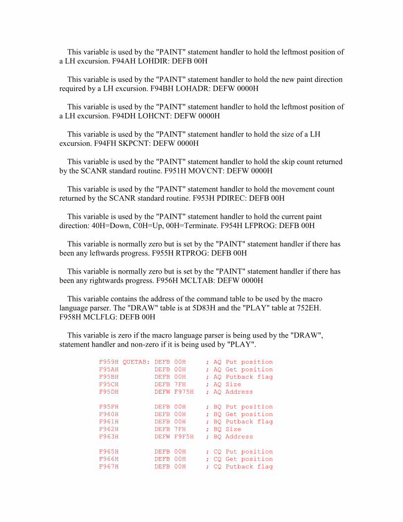
This variable is used by the "PAINT" statement handler to hold the leftmost position of a LH excursion. F94AH LOHDIR: DEFB 00H
This variable is used by the "PAINT" statement handler to hold the new paint direction required by a LH excursion. F94BH LOHADR: DEFW 0000H
This variable is used by the "PAINT" statement handler to hold the leftmost position of a LH excursion. F94DH LOHCNT: DEFW 0000H
This variable is used by the "PAINT" statement handler to hold the size of a LH excursion. F94FH SKPCNT: DEFW 0000H
This variable is used by the "PAINT" statement handler to hold the skip count returned by the SCANR standard routine. F951H MOVCNT: DEFW 0000H
This variable is used by the "PAINT" statement handler to hold the movement count returned by the SCANR standard routine. F953H PDIREC: DEFB 00H
This variable is used by the "PAINT" statement handler to hold the current paint direction: 40H=Down, C0H=Up, 00H=Terminate. F954H LFPROG: DEFB 00H
This variable is normally zero but is set by the "PAINT" statement handler if there has been any leftwards progress. F955H RTPROG: DEFB 00H
This variable is normally zero but is set by the "PAINT" statement handler if there has been any rightwards progress. F956H MCLTAB: DEFW 0000H
This variable contains the address of the command table to be used by the macro language parser. The "DRAW" table is at 5D83H and the "PLAY" table at 752EH. F958H MCLFLG: DEFB 00H
This variable is zero if the macro language parser is being used by the "DRAW", statement handler and non-zero if it is being used by "PLAY".
F959H QUETAB: DEFB 00H ; AQ Put position F95AH DEFB 00H ; AQ Get position F95BH DEFB 00H ; AQ Putback flag F95CH DEFB 7FH ; AQ Size F95DH DEFW F975H ; AQ Address F95FH DEFB 00H ; BQ Put position F960H DEFB 00H ; BQ Get position F961H DEFB 00H ; BQ Putback flag F962H DEFB 7FH ; BQ Size F963H DEFW F9F5H ; BQ Address F965H DEFB 00H ; CQ Put position F966H DEFB 00H ; CQ Get position F967H DEFB 00H ; CQ Putback flag

F968H DEFB 7FH ; CQ Size F969H DEFW FA75H ; CQ Address F96BH DEFB 00H ; RQ Put position F96CH DEFB 00H ; RQ Get position F96DH DEFB 00H ; RQ Putback flag F96EH DEFB 00H ; RQ Size F96FH DEFW 0000H ; RQ Address
These twenty-four variables form the control blocks for the three music queues (VOICAQ, VOICBQ and VOICCQ) and the RS232 queue. The three music control blocks are initialized by the GICINI standard routine and thereafter maintained by the interrupt handler and the PUTQ standard routine. The RS232 control block is unused in the current MSX ROM.
F971H QUEBAK: DEFB 00H ; AQ Putback character F972H DEFB 00H ; BQ Putback character F973H DEFB 00H ; CQ Putback character F974H DEFB 00H ; RQ Putback character
These four variables are used to hold any unwanted character returned to the associated queue. Although the putback facility is implemented in the MSX ROM it is currently unused.
F975H VOICAQ: DEFS 128 ; Voice A queue F9F5H VOICBQ: DEFS 128 ; Voice B queue FA75H VOICCQ: DEFS 128 ; Voice C queue FAF5H RS2IQ : DEFS 64 ; RS232 queue
These four buffers contain the three music queues and the RS232 queue, the latter is unused in MSX and has been redefined in MSX2. FB35H PRSCNT: DEFB 00H
This variable is used by the "PLAY" statement handler to count the number of completed operand strings. Bit 7 is also set after each of the three operands has been parsed to prevent repeated activation of the STRTMS standard routine. FB36H SAVSP : DEFW 0000H
This variable is used by the "PLAY" statement handler to save the Z80 SP before control transfers to the macro language parser. Its value is compared with the SP on return to determine whether any data has been left on the stack because of a queue-full termination by the parser. FB38H VOICEN: DEFB 00H
This variable contains the current voice number being processed by the "PLAY" statement handler. The values 0, 1 and 2 correspond to PSG channels A, B and C. FB39H SAVVOL: DEFW 0000H
This variable is used by the "PLAY" statement "R" command handler to save the current volume setting while a zero- amplitude rest is generated. FB3BH MCLLEN: DEFB 00H
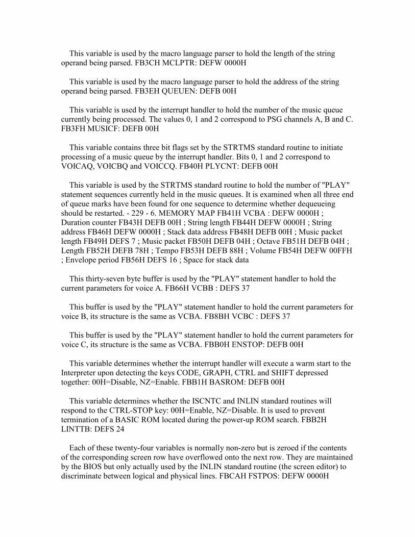
This variable is used by the macro language parser to hold the length of the string operand being parsed. FB3CH MCLPTR: DEFW 0000H
This variable is used by the macro language parser to hold the address of the string operand being parsed. FB3EH QUEUEN: DEFB 00H
This variable is used by the interrupt handler to hold the number of the music queue currently being processed. The values 0, 1 and 2 correspond to PSG channels A, B and C. FB3FH MUSICF: DEFB 00H
This variable contains three bit flags set by the STRTMS standard routine to initiate processing of a music queue by the interrupt handler. Bits 0, 1 and 2 correspond to VOICAQ, VOICBQ and VOICCQ. FB40H PLYCNT: DEFB 00H
This variable is used by the STRTMS standard routine to hold the number of "PLAY" statement sequences currently held in the music queues. It is examined when all three end of queue marks have been found for one sequence to determine whether dequeueing should be restarted. - 229 - 6. MEMORY MAP FB41H VCBA : DEFW 0000H ; Duration counter FB43H DEFB 00H ; String length FB44H DEFW 0000H ; String address FB46H DEFW 0000H ; Stack data address FB48H DEFB 00H ; Music packet length FB49H DEFS 7 ; Music packet FB50H DEFB 04H ; Octave FB51H DEFB 04H ; Length FB52H DEFB 78H ; Tempo FB53H DEFB 88H ; Volume FB54H DEFW 00FFH ; Envelope period FB56H DEFS 16 ; Space for stack data
This thirty-seven byte buffer is used by the "PLAY" statement handler to hold the current parameters for voice A. FB66H VCBB : DEFS 37
This buffer is used by the "PLAY" statement handler to hold the current parameters for voice B, its structure is the same as VCBA. FB8BH VCBC : DEFS 37
This buffer is used by the "PLAY" statement handler to hold the current parameters for voice C, its structure is the same as VCBA. FBB0H ENSTOP: DEFB 00H
This variable determines whether the interrupt handler will execute a warm start to the Interpreter upon detecting the keys CODE, GRAPH, CTRL and SHIFT depressed together: 00H=Disable, NZ=Enable. FBB1H BASROM: DEFB 00H
This variable determines whether the ISCNTC and INLIN standard routines will respond to the CTRL-STOP key: 00H=Enable, NZ=Disable. It is used to prevent termination of a BASIC ROM located during the power-up ROM search. FBB2H LINTTB: DEFS 24
Each of these twenty-four variables is normally non-zero but is zeroed if the contents of the corresponding screen row have overflowed onto the next row. They are maintained by the BIOS but only actually used by the INLIN standard routine (the screen editor) to discriminate between logical and physical lines. FBCAH FSTPOS: DEFW 0000H

This variable is used to hold the cursor coordinates upon entry to the INLIN standard routine. Its function is to restrict the extent of backtracking performed when the text is collected from the screen at termination. FBCCH CURSAV: DEFB 00H
This variable is used to hold the screen character replaced by the text cursor. FBCDH FNKSWI: DEFB 00H
This variable is used by the CHSNS standard routine to determine whether the shifted or unshifted function keys are currently displayed: 00H=Shifted, 01H=Unshifted. FBCEH FNKFLG: DEFS 10
Each of these ten variables is normally zero but is set to 01H if the associated function key has been turned on by a "KEY(n) ON" statement. They are used by the interrupt handler to determine whether, in program mode only, it should return a character string or update the associated entry in TRPTBL. FBD8H ONGSBF: DEFB 00H
This variable is normally zero but is incremented by the interrupt handler whenever a device has achieved the conditions necessary to generate a program interrupt. It is used by the Runloop to determine whether any program interrupts are pending without having to search TRPTBL. FBD9H CLIKFL: DEFB 00H
This variable is used internally by the interrupt handler to prevent spurious key clicks when returning multiple characters from a single key depression such as a function key. FBDAH OLDKEY: DEFS 11
This buffer is used by the interrupt handler to hold the previous state of the keyboard matrix, each byte contains one row of keys starting with row 0. FBE5H NEWKEY: DEFS 11
This buffer is used by the interrupt handler to hold the current state of the keyboard matrix. Key transitions are detected by comparison with the contents of OLDKEY after which OLDKEY is updated with the current state. FBF0H KEYBUF: DEFS 40
This buffer contains the decoded keyboard characters produced by the interrupt handler. Note that the buffer is organized as a circular queue driven by GETPNT and PUTPNT and consequently has no fixed starting point. FC18H LINWRK: DEFS 40
This buffer is used by the BIOS to hold a complete line of screen characters. FC40H PATWRK: DEFS 8
This buffer is used by the BIOS to hold an 8x8 pixel pattern. FC48H BOTTOM: DEFW 8000H
This variable contains the address of the lowest RAM location used by the Interpreter. Its value is set at power-up and thereafter unaltered. FC4AH HIMEM : DEFW F380H
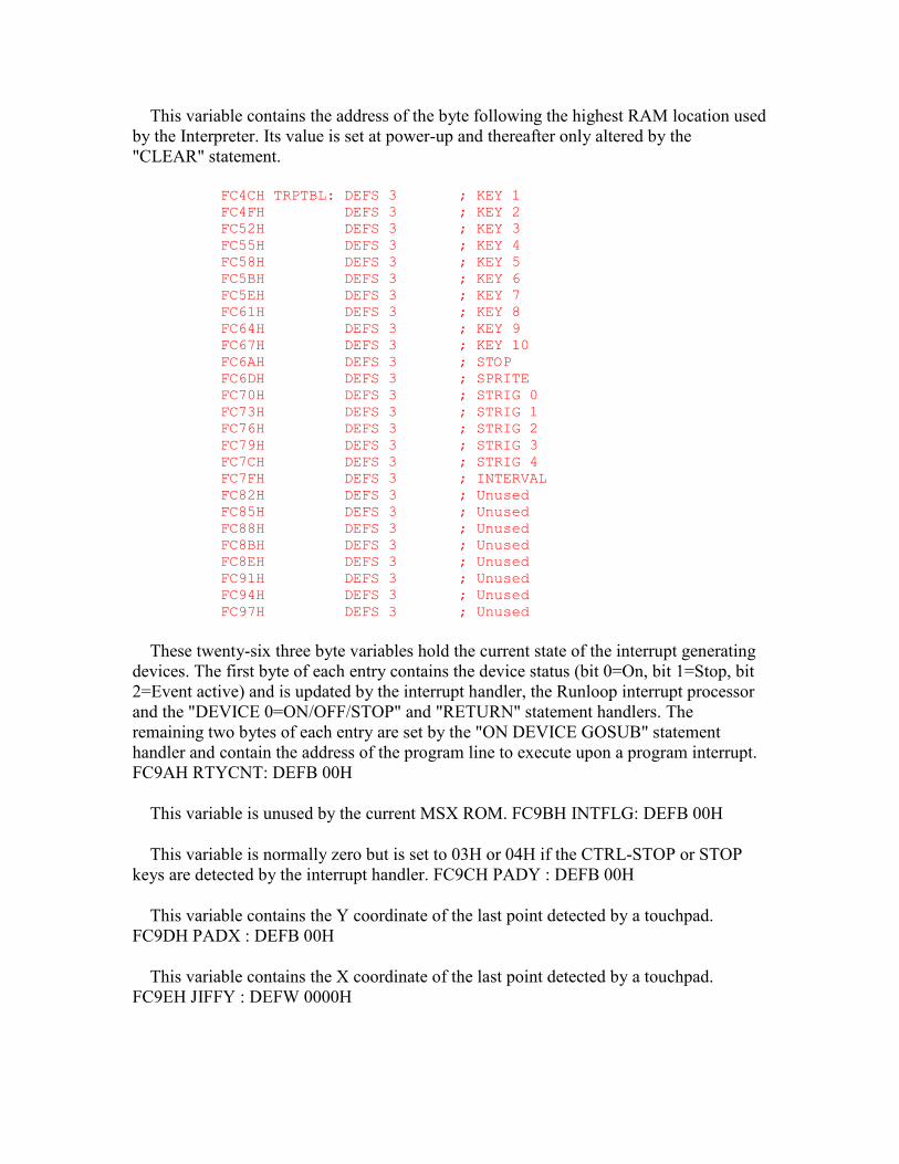
This variable contains the address of the byte following the highest RAM location used by the Interpreter. Its value is set at power-up and thereafter only altered by the "CLEAR" statement.
FC4CH TRPTBL: DEFS 3 ; KEY 1 FC4FH DEFS 3 ; KEY 2 FC52H DEFS 3 ; KEY 3 FC55H DEFS 3 ; KEY 4 FC58H DEFS 3 ; KEY 5 FC5BH DEFS 3 ; KEY 6 FC5EH DEFS 3 ; KEY 7 FC61H DEFS 3 ; KEY 8 FC64H DEFS 3 ; KEY 9 FC67H DEFS 3 ; KEY 10 FC6AH DEFS 3 ; STOP FC6DH DEFS 3 ; SPRITE FC70H DEFS 3 ; STRIG 0 FC73H DEFS 3 ; STRIG 1 FC76H DEFS 3 ; STRIG 2 FC79H DEFS 3 ; STRIG 3 FC7CH DEFS 3 ; STRIG 4 FC7FH DEFS 3 ; INTERVAL FC82H DEFS 3 ; Unused FC85H DEFS 3 ; Unused FC88H DEFS 3 ; Unused FC8BH DEFS 3 ; Unused FC8EH DEFS 3 ; Unused FC91H DEFS 3 ; Unused FC94H DEFS 3 ; Unused FC97H DEFS 3 ; Unused
These twenty-six three byte variables hold the current state of the interrupt generating devices. The first byte of each entry contains the device status (bit 0=On, bit 1=Stop, bit 2=Event active) and is updated by the interrupt handler, the Runloop interrupt processor and the "DEVICE 0=ON/OFF/STOP" and "RETURN" statement handlers. The remaining two bytes of each entry are set by the "ON DEVICE GOSUB" statement handler and contain the address of the program line to execute upon a program interrupt. FC9AH RTYCNT: DEFB 00H
This variable is unused by the current MSX ROM. FC9BH INTFLG: DEFB 00H
This variable is normally zero but is set to 03H or 04H if the CTRL-STOP or STOP keys are detected by the interrupt handler. FC9CH PADY : DEFB 00H
This variable contains the Y coordinate of the last point detected by a touchpad. FC9DH PADX : DEFB 00H
This variable contains the X coordinate of the last point detected by a touchpad. FC9EH JIFFY : DEFW 0000H
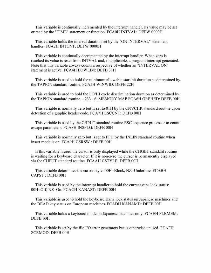
This variable is continually incremented by the interrupt handler. Its value may be set or read by the "TIME" statement or function. FCA0H INTVAL: DEFW 0000H
This variable holds the interval duration set by the "ON INTERVAL" statement handler. FCA2H INTCNT: DEFW 0000H
This variable is continually decremented by the interrupt handler. When zero is reached its value is reset from INTVAL and, if applicable, a program interrupt generated. Note that this variable always counts irrespective of whether an "INTERVAL ON" statement is active. FCA4H LOWLIM: DEFB 31H
This variable is used to hold the minimum allowable start bit duration as determined by the TAPION standard routine. FCA5H WINWID: DEFB 22H
This variable is used to hold the LO/HI cycle discrimination duration as determined by the TAPION standard routine. - 233 - 6. MEMORY MAP FCA6H GRPHED: DEFB 00H
This variable is normally zero but is set to 01H by the CNVCHR standard routine upon detection of a graphic header code. FCA7H ESCCNT: DEFB 00H
This variable is used by the CHPUT standard routine ESC sequence processor to count escape parameters. FCA8H INSFLG: DEFB 00H
This variable is normally zero but is set to FFH by the INLIN standard routine when insert mode is on. FCA9H CSRSW : DEFB 00H
If this variable is zero the cursor is only displayed while the CHGET standard routine is waiting for a keyboard character. If it is non-zero the cursor is permanently displayed via the CHPUT standard routine. FCAAH CSTYLE: DEFB 00H
This variable determines the cursor style: 00H=Block, NZ=Underline. FCABH CAPST : DEFB 00H
This variable is used by the interrupt handler to hold the current caps lock status: 00H=Off, NZ=On. FCACH KANAST: DEFB 00H
This variable is used to hold the keyboard Kana lock status on Japanese machines and the DEAD key status on European machines. FCADH KANAMD: DEFB 00H
This variable holds a keyboard mode on Japanese machines only. FCAEH FLBMEM: DEFB 00H
This variable is set by the file I/O error generators but is otherwise unused. FCAFH SCRMOD: DEFB 00H

This variable contains the current screen mode: 0=40x24 Text Mode, 1=32x24 Text Mode, 2=Graphics Mode, 3=Multicolour Mode. FCB0H OLDSCR: DEFB 00H
This variable holds the screen mode of the last text mode set. - 234 - 6. MEMORY MAP FCB1H CASPRV: DEFB 00H
This variable is used to hold any character returned to an I/O buffer by the cassette putback function. FCB2H BDRATR: DEFB 00H
This variable contains the boundary colour for the "PAINT" statement handler. Its value is set by the PNTINI standard routine and used by the SCANR and SCANL standard routines. FCB3H GXPOS : DEFW 0000H
This variable is used for temporary storage of a graphics X coordinate. FCB5H GYPOS : DEFW 0000H
This variable is used for temporary storage of a graphics Y coordinate. FCB7H GRPACX: DEFW 0000H
This variable contains the current graphics X coordinate for the GRPPRT standard routine. FCB9H GRPACY: DEFW 0000H
This variable contains the current graphics Y coordinate for the GRPPRT standard routine. FCBBH DRWFLG: DEFB 00H
Bits 6 and 7 of this variable are set by the "DRAW" statement "N" and "B" command handlers to turn the associated mode on. FCBCH DRWSCL: DEFB 00H
This variable is used by the "DRAW" statement "S" command handler to hold the current scale factor. FCBDH DRWANG: DEFB 00H
This variable is used by the "DRAW" statement "A" command handler to hold the current angle. FCBEH RUNBNF: DEFB 00H
This variable is normally zero but is set by the "BLOAD" statement handler when an auto-run "R" parameter is specified. FCBFH SAVENT: DEFW 0000H
This variable contains the "BSAVE" and "BLOAD" entry address. - 235 - 6. MEMORY MAP FCC1H EXPTBL: DEFB 00H ; Primary Slot 0 FCC2H DEFB 00H ; Primary Slot 1 FCC3H DEFB 00H ; Primary Slot 2 FCC4H DEFB 00H ; Primary Slot 3
Each of these four variables is normally zero but is set to 80H during the power-up RAM search if the associated Primary Slot is found to be expanded. FCC5H SLTTBL: DEFB 00H ; Primary Slot 0 FCC6H DEFB 00H ; Primary Slot 1 FCC7H DEFB 00H ; Primary Slot 2 FCC8H DEFB 00H ; Primary Slot 3
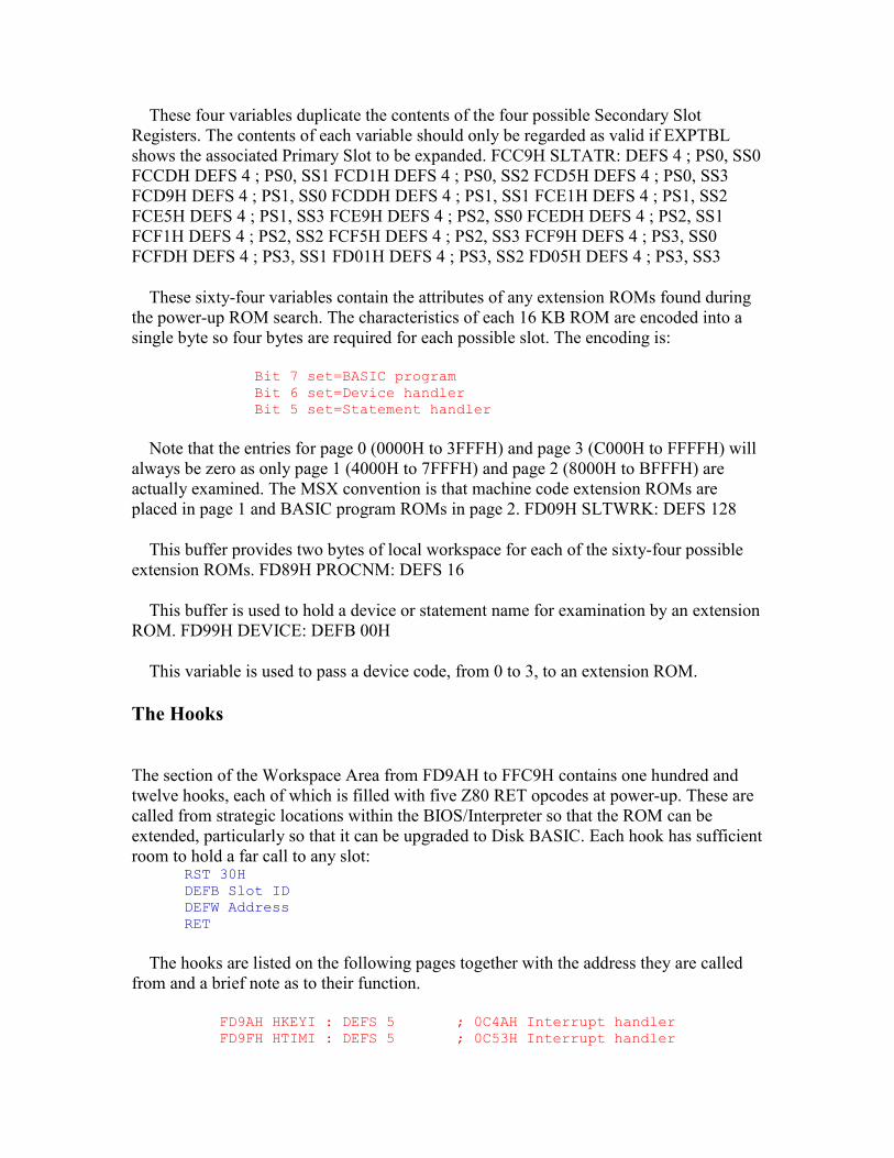
These four variables duplicate the contents of the four possible Secondary Slot Registers. The contents of each variable should only be regarded as valid if EXPTBL shows the associated Primary Slot to be expanded. FCC9H SLTATR: DEFS 4 ; PS0, SS0 FCCDH DEFS 4 ; PS0, SS1 FCD1H DEFS 4 ; PS0, SS2 FCD5H DEFS 4 ; PS0, SS3 FCD9H DEFS 4 ; PS1, SS0 FCDDH DEFS 4 ; PS1, SS1 FCE1H DEFS 4 ; PS1, SS2 FCE5H DEFS 4 ; PS1, SS3 FCE9H DEFS 4 ; PS2, SS0 FCEDH DEFS 4 ; PS2, SS1 FCF1H DEFS 4 ; PS2, SS2 FCF5H DEFS 4 ; PS2, SS3 FCF9H DEFS 4 ; PS3, SS0 FCFDH DEFS 4 ; PS3, SS1 FD01H DEFS 4 ; PS3, SS2 FD05H DEFS 4 ; PS3, SS3
These sixty-four variables contain the attributes of any extension ROMs found during the power-up ROM search. The characteristics of each 16 KB ROM are encoded into a single byte so four bytes are required for each possible slot. The encoding is:
Bit 7 set=BASIC program Bit 6 set=Device handler Bit 5 set=Statement handler
Note that the entries for page 0 (0000H to 3FFFH) and page 3 (C000H to FFFFH) will always be zero as only page 1 (4000H to 7FFFH) and page 2 (8000H to BFFFH) are actually examined. The MSX convention is that machine code extension ROMs are placed in page 1 and BASIC program ROMs in page 2. FD09H SLTWRK: DEFS 128
This buffer provides two bytes of local workspace for each of the sixty-four possible extension ROMs. FD89H PROCNM: DEFS 16
This buffer is used to hold a device or statement name for examination by an extension ROM. FD99H DEVICE: DEFB 00H
This variable is used to pass a device code, from 0 to 3, to an extension ROM.
The Hooks
The section of the Workspace Area from FD9AH to FFC9H contains one hundred and twelve hooks, each of which is filled with five Z80 RET opcodes at power-up. These are called from strategic locations within the BIOS/Interpreter so that the ROM can be extended, particularly so that it can be upgraded to Disk BASIC. Each hook has sufficient room to hold a far call to any slot:
RST 30H DEFB Slot ID DEFW Address RET
The hooks are listed on the following pages together with the address they are called from and a brief note as to their function.
FD9AH HKEYI : DEFS 5 ; 0C4AH Interrupt handler FD9FH HTIMI : DEFS 5 ; 0C53H Interrupt handler
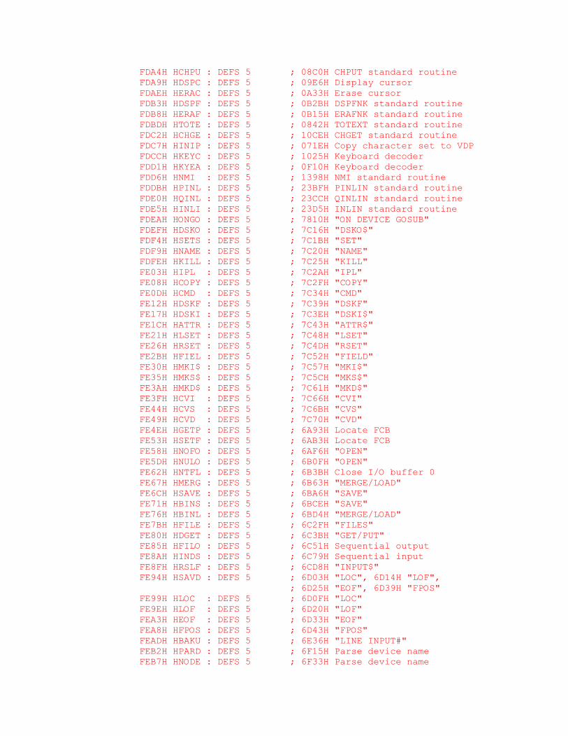
FDA4H HCHPU : DEFS 5 ; 08C0H CHPUT standard routine FDA9H HDSPC : DEFS 5 ; 09E6H Display cursor FDAEH HERAC : DEFS 5 ; 0A33H Erase cursor FDB3H HDSPF : DEFS 5 ; 0B2BH DSPFNK standard routine FDB8H HERAF : DEFS 5 ; 0B15H ERAFNK standard routine FDBDH HTOTE : DEFS 5 ; 0842H TOTEXT standard routine FDC2H HCHGE : DEFS 5 ; 10CEH CHGET standard routine FDC7H HINIP : DEFS 5 ; 071EH Copy character set to VDP FDCCH HKEYC : DEFS 5 ; 1025H Keyboard decoder FDD1H HKYEA : DEFS 5 ; 0F10H Keyboard decoder FDD6H HNMI : DEFS 5 ; 1398H NMI standard routine FDDBH HPINL : DEFS 5 ; 23BFH PINLIN standard routine FDE0H HQINL : DEFS 5 ; 23CCH QINLIN standard routine FDE5H HINLI : DEFS 5 ; 23D5H INLIN standard routine FDEAH HONGO : DEFS 5 ; 7810H "ON DEVICE GOSUB" FDEFH HDSKO : DEFS 5 ; 7C16H "DSKO$" FDF4H HSETS : DEFS 5 ; 7C1BH "SET" FDF9H HNAME : DEFS 5 ; 7C20H "NAME" FDFEH HKILL : DEFS 5 ; 7C25H "KILL" FE03H HIPL : DEFS 5 ; 7C2AH "IPL" FE08H HCOPY : DEFS 5 ; 7C2FH "COPY" FE0DH HCMD : DEFS 5 ; 7C34H "CMD" FE12H HDSKF : DEFS 5 ; 7C39H "DSKF" FE17H HDSKI : DEFS 5 ; 7C3EH "DSKI$" FE1CH HATTR : DEFS 5 ; 7C43H "ATTR$" FE21H HLSET : DEFS 5 ; 7C48H "LSET" FE26H HRSET : DEFS 5 ; 7C4DH "RSET" FE2BH HFIEL : DEFS 5 ; 7C52H "FIELD" FE30H HMKI$ : DEFS 5 ; 7C57H "MKI$" FE35H HMKS$ : DEFS 5 ; 7C5CH "MKS$" FE3AH HMKD$ : DEFS 5 ; 7C61H "MKD$" FE3FH HCVI : DEFS 5 ; 7C66H "CVI" FE44H HCVS : DEFS 5 ; 7C6BH "CVS" FE49H HCVD : DEFS 5 ; 7C70H "CVD" FE4EH HGETP : DEFS 5 ; 6A93H Locate FCB FE53H HSETF : DEFS 5 ; 6AB3H Locate FCB FE58H HNOFO : DEFS 5 ; 6AF6H "OPEN" FE5DH HNULO : DEFS 5 ; 6B0FH "OPEN" FE62H HNTFL : DEFS 5 ; 6B3BH Close I/O buffer 0 FE67H HMERG : DEFS 5 ; 6B63H "MERGE/LOAD" FE6CH HSAVE : DEFS 5 ; 6BA6H "SAVE" FE71H HBINS : DEFS 5 ; 6BCEH "SAVE" FE76H HBINL : DEFS 5 ; 6BD4H "MERGE/LOAD" FE7BH HFILE : DEFS 5 ; 6C2FH "FILES" FE80H HDGET : DEFS 5 ; 6C3BH "GET/PUT" FE85H HFILO : DEFS 5 ; 6C51H Sequential output FE8AH HINDS : DEFS 5 ; 6C79H Sequential input FE8FH HRSLF : DEFS 5 ; 6CD8H "INPUT$" FE94H HSAVD : DEFS 5 ; 6D03H "LOC", 6D14H "LOF", ; 6D25H "EOF", 6D39H "FPOS" FE99H HLOC : DEFS 5 ; 6D0FH "LOC" FE9EH HLOF : DEFS 5 ; 6D20H "LOF" FEA3H HEOF : DEFS 5 ; 6D33H "EOF" FEA8H HFPOS : DEFS 5 ; 6D43H "FPOS" FEADH HBAKU : DEFS 5 ; 6E36H "LINE INPUT#" FEB2H HPARD : DEFS 5 ; 6F15H Parse device name FEB7H HNODE : DEFS 5 ; 6F33H Parse device name
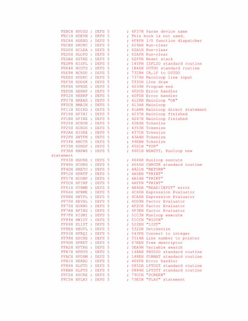
FEBCH HPOSD : DEFS 5 ; 6F37H Parse device name FEC1H HDEVN : DEFS 5 ; This hook is not used. FEC6H HGEND : DEFS 5 ; 6F8FH I/O function dispatcher FECBH HRUNC : DEFS 5 ; 629AH Run-clear FED0H HCLEA : DEFS 5 ; 62A1H Run-clear FED5H HLOPD : DEFS 5 ; 62AFH Run-clear FEDAH HSTKE : DEFS 5 ; 62F0H Reset stack FEDFH HISFL : DEFS 5 ; 145FH ISFLIO standard routine FEE4H HOUTD : DEFS 5 ; 1B46H OUTDO standard routine FEE9H HCRDO : DEFS 5 ; 7328H CR,LF to OUTDO FEEEH HDSKC : DEFS 5 ; 7374H Mainloop line input FEF3H HDOGR : DEFS 5 ; 593CH Line draw FEF8H HPRGE : DEFS 5 ; 4039H Program end FEFDH HERRP : DEFS 5 ; 40DCH Error handler FF02H HERRF : DEFS 5 ; 40FDH Error handler FF07H HREAD : DEFS 5 ; 4128H Mainloop "OK" FF0CH HMAIN : DEFS 5 ; 4134H Mainloop FF11H HDIRD : DEFS 5 ; 41A8H Mainloop direct statement FF16H HFINI : DEFS 5 ; 4237H Mainloop finished FF1BH HFINE : DEFS 5 ; 4247H Mainloop finished FF20H HCRUN : DEFS 5 ; 42B9H Tokenize FF25H HCRUS : DEFS 5 ; 4353H Tokenize FF2AH HISRE : DEFS 5 ; 437CH Tokenize FF2FH HNTFN : DEFS 5 ; 43A4H Tokenize FF34H HNOTR : DEFS 5 ; 44EBH Tokenize FF39H HSNGF : DEFS 5 ; 45D1H "FOR" FF3EH HNEWS : DEFS 5 ; 4601H NEWSTT, Runloop new statement FF43H HGONE : DEFS 5 ; 4646H Runloop execute FF48H HCHRG : DEFS 5 ; 4666H CHRGTR standard routine FF4DH HRETU : DEFS 5 ; 4821H "RETURN" FF52H HPRTF : DEFS 5 ; 4A5EH "PRINT" FF57H HCOMP : DEFS 5 ; 4A54H "PRINT" FF5CH HFINP : DEFS 5 ; 4AFFH "PRINT" FF61H HTRMN : DEFS 5 ; 4B4DH "READ/INPUT" error FF66H HFRME : DEFS 5 ; 4C6DH Expression Evaluator FF6BH HNTPL : DEFS 5 ; 4CA6H Expression Evaluator FF70H HEVAL : DEFS 5 ; 4DD9H Factor Evaluator FF75H HOKNO : DEFS 5 ; 4F2CH Factor Evaluator FF7AH HFING : DEFS 5 ; 4F3EH Factor Evaluator FF7FH HISMI : DEFS 5 ; 51C3H Runloop execute FF84H HWIDT : DEFS 5 ; 51CCH "WIDTH" FF89H HLIST : DEFS 5 ; 522EH "LIST" FF8EH HBUFL : DEFS 5 ; 532DH Detokenize FF93H HFRQI : DEFS 5 ; 543FH Convert to integer FF98H HSCNE : DEFS 5 ; 5514H Line number to pointer FF9DH HFRET : DEFS 5 ; 67EEH Free descriptor FFA2H HPTRG : DEFS 5 ; 5EA9H Variable search FFA7H HPHYD : DEFS 5 ; 148AH PHYDIO standard routine FFACH HFORM : DEFS 5 ; 148EH FORMAT standard routine FFB1H HERRO : DEFS 5 ; 406FH Error handler FFB6H HLPTO : DEFS 5 ; 085DH LPTOUT standard routine FFBBH HLPTS : DEFS 5 ; 0884H LPTSTT standard routine FFC0H HSCRE : DEFS 5 ; 79CCH "SCREEN" FFC5H HPLAY : DEFS 5 ; 73E5H "PLAY" statement
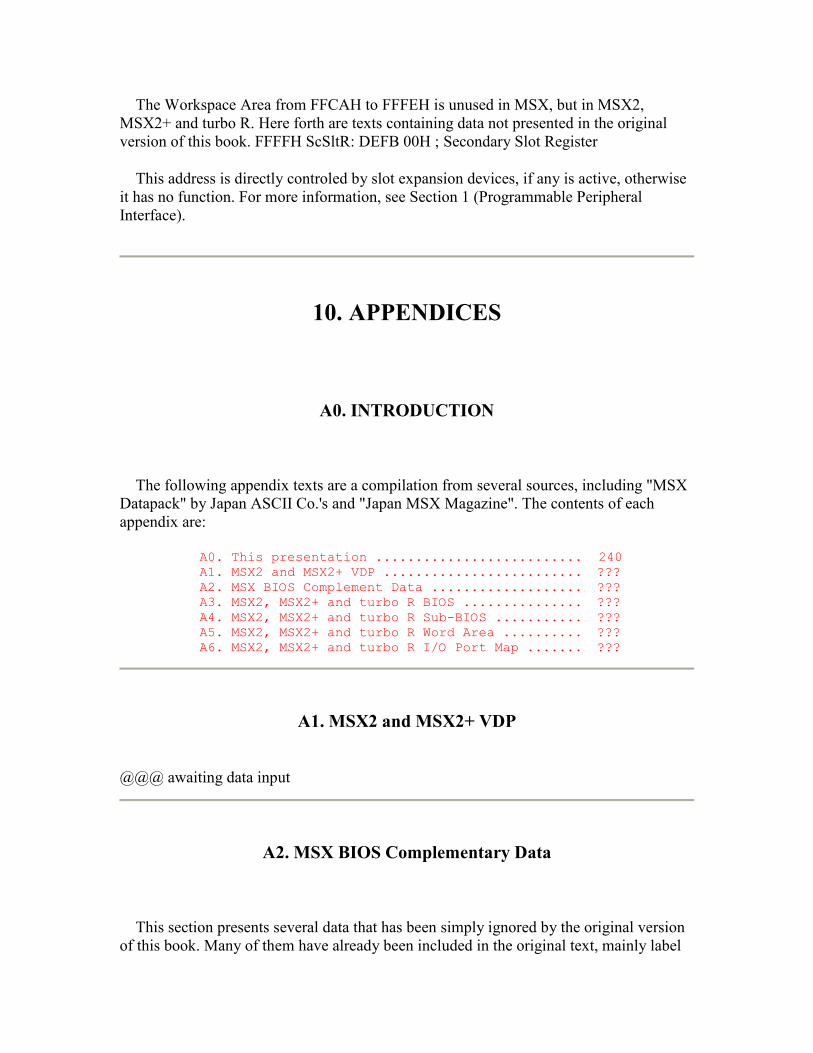
The Workspace Area from FFCAH to FFFEH is unused in MSX, but in MSX2, MSX2+ and turbo R. Here forth are texts containing data not presented in the original version of this book. FFFFH ScSltR: DEFB 00H ; Secondary Slot Register
This address is directly controled by slot expansion devices, if any is active, otherwise it has no function. For more information, see Section 1 (Programmable Peripheral Interface).
10. APPENDICES
A0. INTRODUCTION
The following appendix texts are a compilation from several sources, including "MSX Datapack" by Japan ASCII Co.'s and "Japan MSX Magazine". The contents of each appendix are:
A0. This presentation .......................... 240 A1. MSX2 and MSX2+ VDP ......................... ??? A2. MSX BIOS Complement Data ................... ??? A3. MSX2, MSX2+ and turbo R BIOS ............... ??? A4. MSX2, MSX2+ and turbo R Sub-BIOS ........... ??? A5. MSX2, MSX2+ and turbo R Word Area .......... ??? A6. MSX2, MSX2+ and turbo R I/O Port Map ....... ???
A1. MSX2 and MSX2+ VDP
@@@ awaiting data input
A2. MSX BIOS Complementary Data
This section presents several data that has been simply ignored by the original version of this book. Many of them have already been included in the original text, mainly label
names and entry and exit data, but it was impossible to include everything without changing all the page numbers.
The topics covered by this section are:
• MSX ROM Version Identification Bytes; • MSX Math-Pack.
- ??? -
7.A4. MSX2, MSX2+ and turbo R Sub-BIOS
@@@ awaiting data input
7.A5. Work Area
The Work Area of MSX2, MSX2+ and turbo R are very similar of MSX's one. The only differences are in the RS2IQ area (from FAF5H to FB34H), which has been divided in two, from FAF5H to FB02 for new MSX features and from FB03 to FB34H for RS-232C and some system variables, and the last bytes of the RAM, after the hooks (from FFCAH to FFFEH).
The MSX-Disk work area has the following entries: F323 DISKVE: DEFS 2 F325 BREAKV: DEFS 2 F341 RAMAD0: DEFS 1 F342 RAMAD1: DEFS 1 F343 RAMAD2: DEFS 1 F344 RAMAD3: DEFS 1 F348 MASTERS: DEFS 1 F37D BDOS: DEFS 2 ; MSX-Disk BIOS Function Call. F24F HPROMPT: DEFS 5 FAF5 DPPAGE: DEFB 0 ; Current Display Page.
The number of the VDP page currently displayed (MSX2, MSX2+, turbo R). FAF6 ACPAGE: DEFB 0 ; Active Access Page.
The number of the VDP page actually accessed (MSX2, MSX2+, turbo R). FAF7 AVCSAV: DEFS 1 ; AV Control Board Save state.
Used by MSX AV Control boards (MSX, MSX2, MSX2+, turbo R). FAF8 EXBRSA: DEFS 1 ; Extended BIOS Sub-ROM slot Id. Save.
Slot identification of the extended BIOS Sub-ROM (MSX2, MSX2+, turbo R). FAF9 CHRCNT: DEFS 1 ; Character Counter.
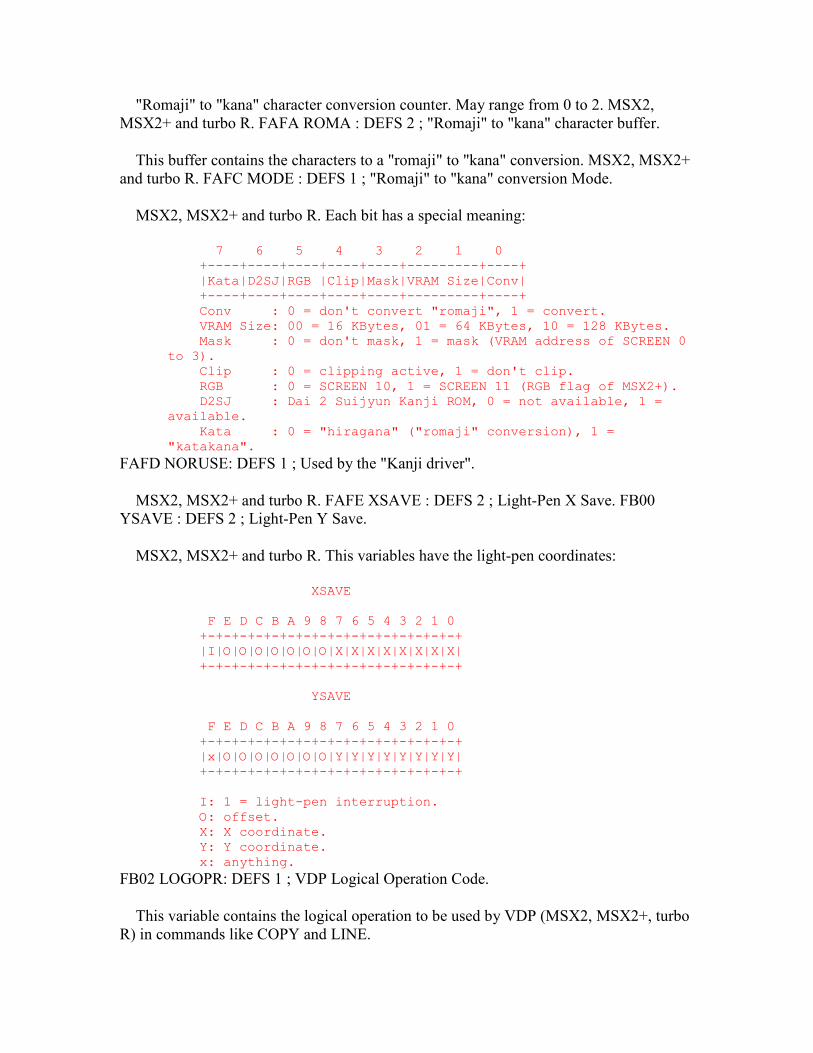
"Romaji" to "kana" character conversion counter. May range from 0 to 2. MSX2, MSX2+ and turbo R. FAFA ROMA : DEFS 2 ; "Romaji" to "kana" character buffer.
This buffer contains the characters to a "romaji" to "kana" conversion. MSX2, MSX2+ and turbo R. FAFC MODE : DEFS 1 ; "Romaji" to "kana" conversion Mode.
MSX2, MSX2+ and turbo R. Each bit has a special meaning:
7 6 5 4 3 2 1 0 +----+----+----+----+----+---------+----+ |Kata|D2SJ|RGB |Clip|Mask|VRAM Size|Conv| +----+----+----+----+----+---------+----+ Conv : 0 = don't convert "romaji", 1 = convert. VRAM Size: 00 = 16 KBytes, 01 = 64 KBytes, 10 = 128 KBytes. Mask : 0 = don't mask, 1 = mask (VRAM address of SCREEN 0 to 3). Clip : 0 = clipping active, 1 = don't clip. RGB : 0 = SCREEN 10, 1 = SCREEN 11 (RGB flag of MSX2+). D2SJ : Dai 2 Suijyun Kanji ROM, 0 = not available, 1 = available. Kata : 0 = "hiragana" ("romaji" conversion), 1 = "katakana".
FAFD NORUSE: DEFS 1 ; Used by the "Kanji driver".
MSX2, MSX2+ and turbo R. FAFE XSAVE : DEFS 2 ; Light-Pen X Save. FB00 YSAVE : DEFS 2 ; Light-Pen Y Save.
MSX2, MSX2+ and turbo R. This variables have the light-pen coordinates:
XSAVE F E D C B A 9 8 7 6 5 4 3 2 1 0 +-+-+-+-+-+-+-+-+-+-+-+-+-+-+-+-+ |I|O|O|O|O|O|O|O|X|X|X|X|X|X|X|X| +-+-+-+-+-+-+-+-+-+-+-+-+-+-+-+-+ YSAVE F E D C B A 9 8 7 6 5 4 3 2 1 0 +-+-+-+-+-+-+-+-+-+-+-+-+-+-+-+-+ |x|O|O|O|O|O|O|O|Y|Y|Y|Y|Y|Y|Y|Y| +-+-+-+-+-+-+-+-+-+-+-+-+-+-+-+-+ I: 1 = light-pen interruption. O: offset. X: X coordinate. Y: Y coordinate. x: anything.
FB02 LOGOPR: DEFS 1 ; VDP Logical Operation Code.
This variable contains the logical operation to be used by VDP (MSX2, MSX2+, turbo R) in commands like COPY and LINE.
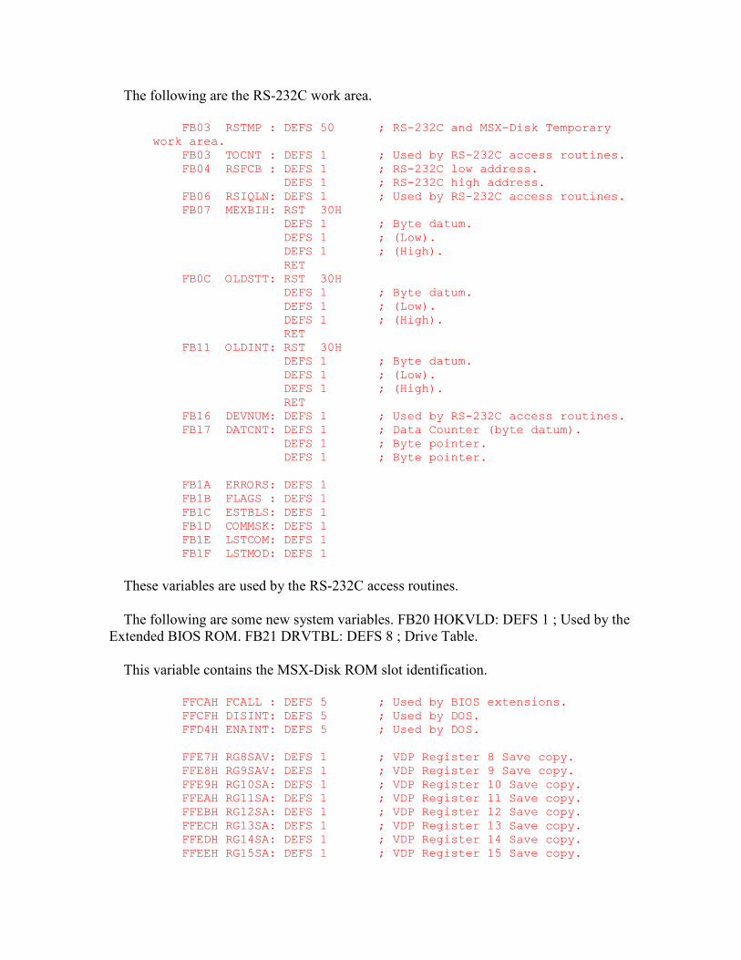
The following are the RS-232C work area.
FB03 RSTMP : DEFS 50 ; RS-232C and MSX-Disk Temporary work area. FB03 TOCNT : DEFS 1 ; Used by RS-232C access routines. FB04 RSFCB : DEFS 1 ; RS-232C low address. DEFS 1 ; RS-232C high address. FB06 RSIQLN: DEFS 1 ; Used by RS-232C access routines. FB07 MEXBIH: RST 30H DEFS 1 ; Byte datum. DEFS 1 ; (Low). DEFS 1 ; (High). RET FB0C OLDSTT: RST 30H DEFS 1 ; Byte datum. DEFS 1 ; (Low). DEFS 1 ; (High). RET FB11 OLDINT: RST 30H DEFS 1 ; Byte datum. DEFS 1 ; (Low). DEFS 1 ; (High). RET FB16 DEVNUM: DEFS 1 ; Used by RS-232C access routines. FB17 DATCNT: DEFS 1 ; Data Counter (byte datum). DEFS 1 ; Byte pointer. DEFS 1 ; Byte pointer. FB1A ERRORS: DEFS 1 FB1B FLAGS : DEFS 1 FB1C ESTBLS: DEFS 1 FB1D COMMSK: DEFS 1 FB1E LSTCOM: DEFS 1 FB1F LSTMOD: DEFS 1
These variables are used by the RS-232C access routines.
The following are some new system variables. FB20 HOKVLD: DEFS 1 ; Used by the Extended BIOS ROM. FB21 DRVTBL: DEFS 8 ; Drive Table.
This variable contains the MSX-Disk ROM slot identification.
FFCAH FCALL : DEFS 5 ; Used by BIOS extensions. FFCFH DISINT: DEFS 5 ; Used by DOS. FFD4H ENAINT: DEFS 5 ; Used by DOS. FFE7H RG8SAV: DEFS 1 ; VDP Register 8 Save copy. FFE8H RG9SAV: DEFS 1 ; VDP Register 9 Save copy. FFE9H RG10SA: DEFS 1 ; VDP Register 10 Save copy. FFEAH RG11SA: DEFS 1 ; VDP Register 11 Save copy. FFEBH RG12SA: DEFS 1 ; VDP Register 12 Save copy. FFECH RG13SA: DEFS 1 ; VDP Register 13 Save copy. FFEDH RG14SA: DEFS 1 ; VDP Register 14 Save copy. FFEEH RG15SA: DEFS 1 ; VDP Register 15 Save copy.
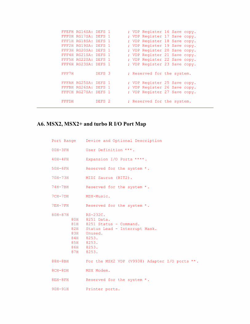
FFEFH RG16SA: DEFS 1 ; VDP Register 16 Save copy. FFF0H RG17SA: DEFS 1 ; VDP Register 17 Save copy. FFF1H RG18SA: DEFS 1 ; VDP Register 18 Save copy. FFF2H RG19SA: DEFS 1 ; VDP Register 19 Save copy. FFF3H RG20SA: DEFS 1 ; VDP Register 20 Save copy. FFF4H RG21SA: DEFS 1 ; VDP Register 21 Save copy. FFF5H RG22SA: DEFS 1 ; VDP Register 22 Save copy. FFF6H RG23SA: DEFS 1 ; VDP Register 23 Save copy. FFF7H DEFS 3 ; Reserved for the system. FFFAH RG25SA: DEFS 1 ; VDP Register 25 Save copy. FFFBH RG26SA: DEFS 1 ; VDP Register 26 Save copy. FFFCH RG27SA: DEFS 1 ; VDP Register 27 Save copy. FFFDH DEFS 2 ; Reserved for the system.
A6. MSX2, MSX2+ and turbo R I/O Port Map
Port Range Device and Optional Description 00H-3FH User Definition ***. 40H-4FH Expansion I/O Ports ****. 50H-6FH Reserved for the system *. 70H-73H MIDI Saurus (BIT2). 74H-7BH Reserved for the system *. 7CH-7DH MSX-Music. 7EH-7FH Reserved for the system *. 80H-87H RS-232C. 80H 8251 Data. 81H 8251 Status - Command. 82H Status Lead - Interrupt Mask. 83H Unused. 84H 8253. 85H 8253. 86H 8253. 87H 8253. 88H-8BH For the MSX2 VDP (V9938) Adapter I/O ports **. 8CH-8DH MSX Modem. 8EH-8FH Reserved for the system *. 90H-91H Printer ports.
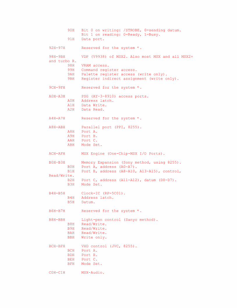
90H Bit 0 on writing: /STROBE, 0=sending datum. Bit 1 on reading: 0=Ready, 1=Busy. 91H Data port. 92H-97H Reserved for the system *. 98H-9BH VDP (V9938) of MSX2. Also most MSX and all MSX2+ and turbo R. 98H VRAM access. 99H Command register access. 9AH Palette register access (write only). 9BH Register indirect assignment (write only). 9CH-9FH Reserved for the system *. A0H-A3H PSG (AY-3-8910) access ports. A0H Address latch. A1H Data Write. A2H Data Read. A4H-A7H Reserved for the system *. A8H-ABH Parallel port (PPI, 8255). A8H Port A. A9H Port B. AAH Port C. ABH Mode Set. ACH-AFH MSX Engine (One-Chip-MSX I/O Ports). B0H-B3H Memory Expansion (Sony method, using 8255). B0H Port A, address (A0-A7). B1H Port B, address (A8-A10, A13-A15), control, Read/Write. B2H Port C, address (A11-A12), datum (D0-D7). B3H Mode Set. B4H-B5H Clock-IC (RP-5C01). B4H Address latch. B5H Datum. B6H-B7H Reserved for the system *. B8H-BBH Light-pen control (Sanyo method). B8H Read/Write. B9H Read/Write. BAH Read/Write. BBH Write only. BCH-BFH VHD control (JVC, 8255). BCH Port A. BDH Port B. BEH Port C. BFH Mode Set. C0H-C1H MSX-Audio.
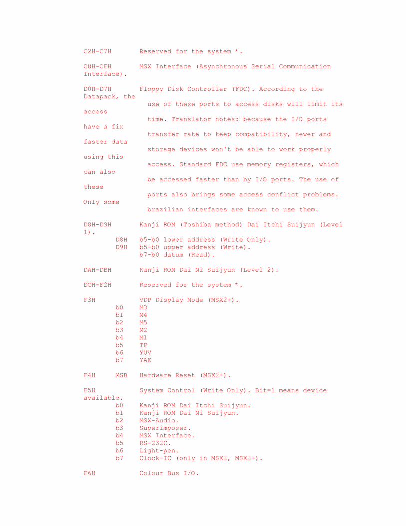
C2H-C7H Reserved for the system *. C8H-CFH MSX Interface (Asynchronous Serial Communication Interface). D0H-D7H Floppy Disk Controller (FDC). According to the Datapack, the use of these ports to access disks will limit its access time. Translator notes: because the I/O ports have a fix transfer rate to keep compatibility, newer and faster data storage devices won't be able to work properly using this access. Standard FDC use memory registers, which can also be accessed faster than by I/O ports. The use of these ports also brings some access conflict problems. Only some brazilian interfaces are known to use them. D8H-D9H Kanji ROM (Toshiba method) Dai Itchi Suijyun (Level 1). D8H b5-b0 lower address (Write Only). D9H b5-b0 upper address (Write). b7-b0 datum (Read). DAH-DBH Kanji ROM Dai Ni Suijyun (Level 2). DCH-F2H Reserved for the system *. F3H VDP Display Mode (MSX2+). b0 M3 b1 M4 b2 M5 b3 M2 b4 M1 b5 TP b6 YUV b7 YAE F4H MSB Hardware Reset (MSX2+). F5H System Control (Write Only). Bit=1 means device available. b0 Kanji ROM Dai Itchi Suijyun. b1 Kanji ROM Dai Ni Suijyun. b2 MSX-Audio. b3 Superimposer. b4 MSX Interface. b5 RS-232C. b6 Light-pen. b7 Clock-IC (only in MSX2, MSX2+). F6H Colour Bus I/O.
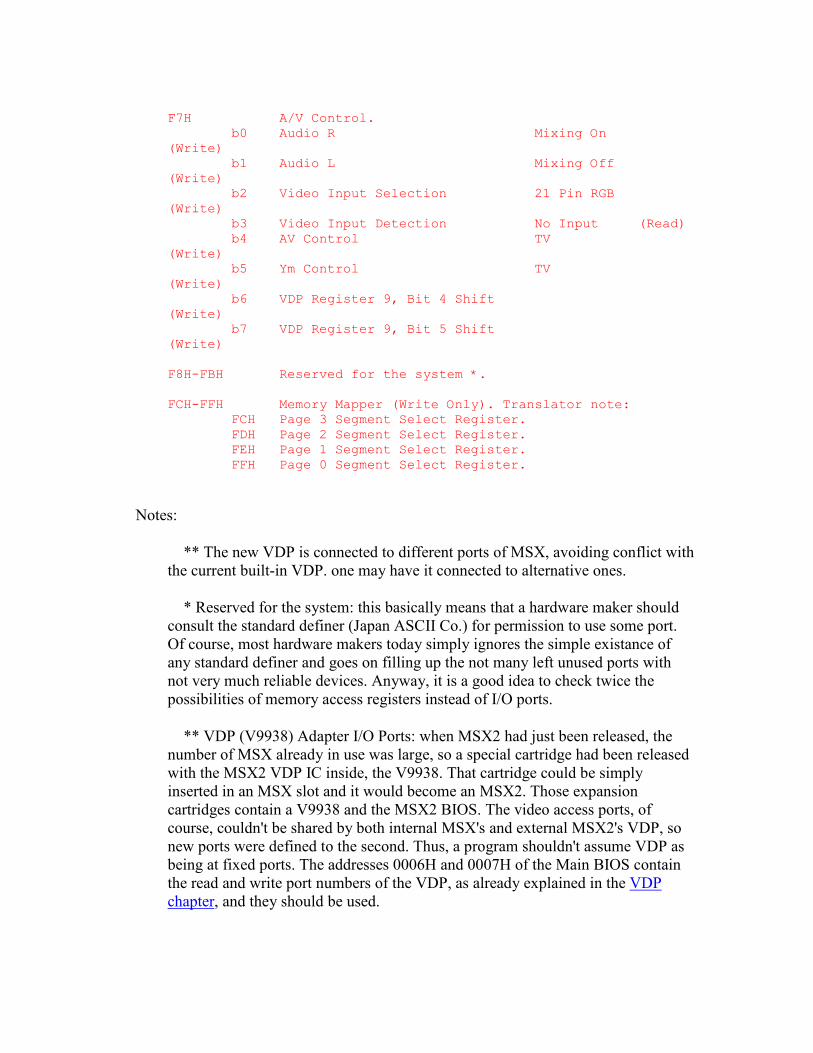
F7H A/V Control. b0 Audio R Mixing On (Write) b1 Audio L Mixing Off (Write) b2 Video Input Selection 21 Pin RGB (Write) b3 Video Input Detection No Input (Read) b4 AV Control TV (Write) b5 Ym Control TV (Write) b6 VDP Register 9, Bit 4 Shift (Write) b7 VDP Register 9, Bit 5 Shift (Write) F8H-FBH Reserved for the system *. FCH-FFH Memory Mapper (Write Only). Translator note: FCH Page 3 Segment Select Register. FDH Page 2 Segment Select Register. FEH Page 1 Segment Select Register. FFH Page 0 Segment Select Register.
Notes:
** The new VDP is connected to different ports of MSX, avoiding conflict with the current built-in VDP. one may have it connected to alternative ones.
* Reserved for the system: this basically means that a hardware maker should consult the standard definer (Japan ASCII Co.) for permission to use some port. Of course, most hardware makers today simply ignores the simple existance of any standard definer and goes on filling up the not many left unused ports with not very much reliable devices. Anyway, it is a good idea to check twice the possibilities of memory access registers instead of I/O ports.
** VDP (V9938) Adapter I/O Ports: when MSX2 had just been released, the number of MSX already in use was large, so a special cartridge had been released with the MSX2 VDP IC inside, the V9938. That cartridge could be simply inserted in an MSX slot and it would become an MSX2. Those expansion cartridges contain a V9938 and the MSX2 BIOS. The video access ports, of course, couldn't be shared by both internal MSX's and external MSX2's VDP, so new ports were defined to the second. Thus, a program shouldn't assume VDP as being at fixed ports. The addresses 0006H and 0007H of the Main BIOS contain the read and write port numbers of the VDP, as already explained in the VDP chapter, and they should be used.
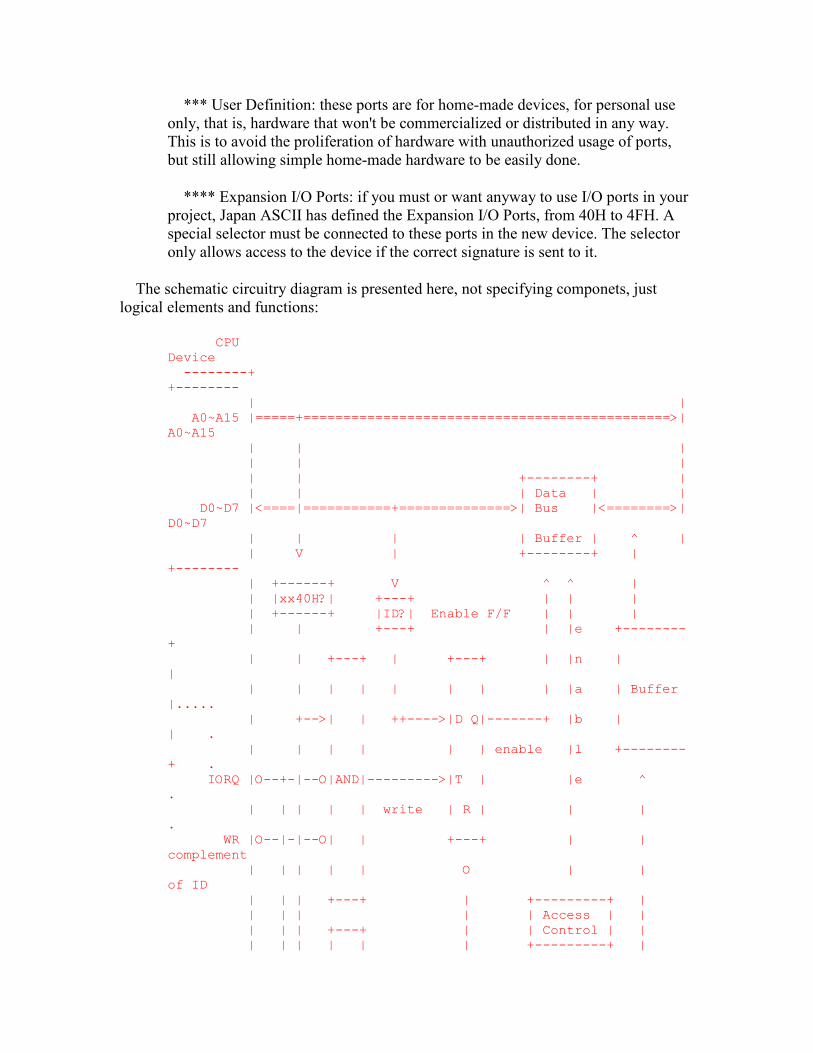
*** User Definition: these ports are for home-made devices, for personal use only, that is, hardware that won't be commercialized or distributed in any way. This is to avoid the proliferation of hardware with unauthorized usage of ports, but still allowing simple home-made hardware to be easily done.
**** Expansion I/O Ports: if you must or want anyway to use I/O ports in your project, Japan ASCII has defined the Expansion I/O Ports, from 40H to 4FH. A special selector must be connected to these ports in the new device. The selector only allows access to the device if the correct signature is sent to it.
The schematic circuitry diagram is presented here, not specifying componets, just logical elements and functions:
CPU Device --------+ +-------- | | A0~A15 |=====+==============================================>| A0~A15 | | | | | | | | +--------+ | | | | Data | | D0~D7 |<====|===========+==============>| Bus |<========>| D0~D7 | | | | Buffer | ^ | | V | +--------+ | +-------- | +------+ V ^ ^ | | |xx40H?| +---+ | | | | +------+ |ID?| Enable F/F | | | | | +---+ | |e +--------+ | | +---+ | +---+ | |n | | | | | | | | | | |a | Buffer |..... | +-->| | ++---->|D Q|-------+ |b | | . | | | | | | enable |l +--------+ . IORQ |O--+-|--O|AND|--------->|T | |e ^ . | | | | | write | R | | | . WR |O--|-|--O| | +---+ | | complement | | | | | O | | of ID | | | +---+ | +---------+ | | | | | | Access | | | | | +---+ | | Control | | | | | | | | +---------+ |
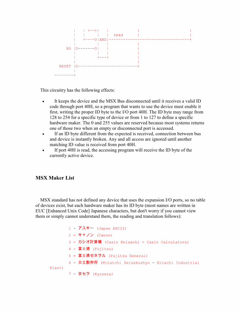
| | +-->| | | | | | | | read | | | +----O|AND|----------------------------------+ | | | | RD |O-------O| | | | | | | | +---+ | | | RESET |O-------------------------+ | --------+
This circuitry has the following effects:
• It keeps the device and the MSX Bus disconnected until it receives a valid ID code through port 40H, so a program that wants to use the device must enable it first, writing the proper ID byte to the I/O port 40H. The ID byte may range from 128 to 254 for a specific type of device or from 1 to 127 to define a specific hardware maker. The 0 and 255 values are reserved because most systems returns one of those two when an empty or disconnected port is accessed.
• If an ID byte different from the expected is received, connection between bus and device is instantly broken. Any and all access are ignored until another matching ID value is received from port 40H.
• If port 40H is read, the accessing program will receive the ID byte of the currently active device.
MSX Maker List
MSX standard has not defined any device that uses the expansion I/O ports, so no table of devices exist, but each hardware maker has its ID byte (most names are written in EUC [Enhanced Unix Code] Japanese characters, but don't worry if you cannot view them or simply cannot understand them, the reading and translation follows):
1 = アスキー (Japan ASCII)
2 = キャノン (Canon)
3 = カシオ計算機 (Casio Keisanki = Casio Calculators)
4 = 富士通 (Fujitsu)
5 = 富士通ゼネラル (Fujitsu General)
6 = 日立製作所 (Hitatchi Seisakushyo = Hitachi Industrial
Plant)
7 = 京セラ (Kyosera)
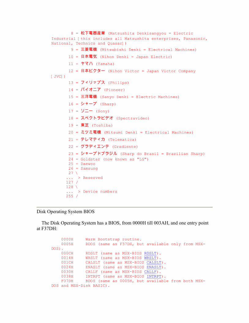
8 = 松下電器産業 (Matsushita Denkisangyou = Electric
Industrial [this includes all Matsushita enterprises, Panasonic, National, Technics and Quasar])
9 = 三菱電機 (Mitsubishi Denki = Electrical Machines)
10 = 日本電気 (Nihon Denki = Japan Electric)
11 = ヤマハ (Yamaha)
12 = 日本ビクター (Nihon Victor = Japan Victor Company
[JVC])
13 = フィリップス (Philips)
14 = パイオニア (Pioneer)
15 = 三洋電機 (Sanyo Denki = Electric Machines)
16 = シャープ (Sharp)
17 = ソニー (Sony)
18 = スペクトラビデオ (Spectravideo)
19 = 東芝 (Toshiba)
20 = ミツミ電機 (Mitsumi Denki = Electrical Machines)
21 = テレマティカ (Telematica)
22 = グラディエンテ (Gradiente)
23 = シャープドブラジル (Sharp do Brasil = Brazilian Sharp)
24 = Goldstar (now known as "LG") 25 = Daewoo 26 = Samsung 27 \ ... > Reserved 127 / 128 \ ... > Device numbers 255 /
Disk Operating System BIOS
The Disk Operating System has a BIOS, from 0000H till 003AH, and one entry point at F37DH:
0000H Warm Bootstrap routine. 0005H BDOS (same as F37DH, but available only from MSX-DOS). 000CH RDSLT (same as MSX-BIOS RDSLT). 0014H WRSLT (same as MSX-BIOS WRSLT). 001CH CALSLT (same as MSX-BIOS CALSLT). 0024H ENASLT (same as MSX-BIOS ENASLT). 0030H CALLF (same as MSX-BIOS CALLF). 0038H INTRPT (same as MSX-BIOS INTRPT). F37DH BDOS (same as 0005H, but available from both MSX-DOS and MSX-Disk BASIC).
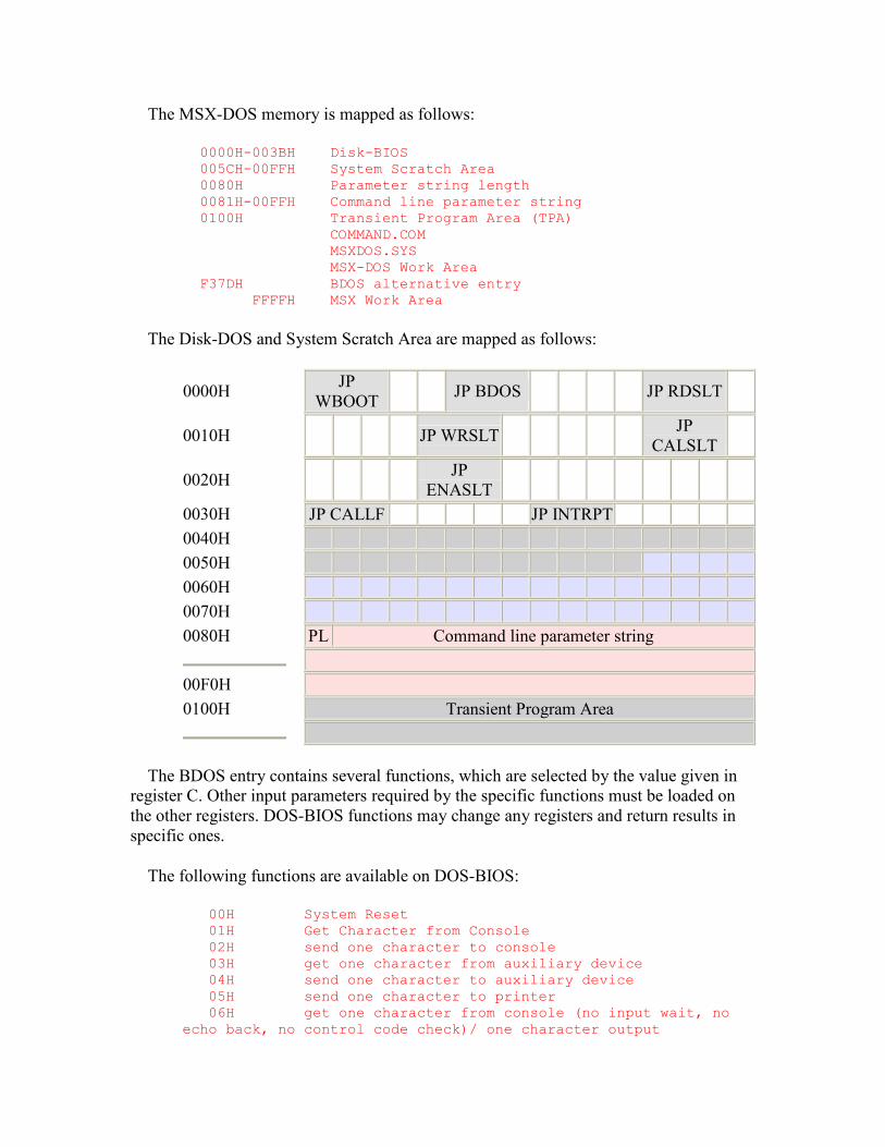
The MSX-DOS memory is mapped as follows:
0000H-003BH Disk-BIOS 005CH-00FFH System Scratch Area 0080H Parameter string length 0081H-00FFH Command line parameter string 0100H Transient Program Area (TPA) COMMAND.COM MSXDOS.SYS MSX-DOS Work Area F37DH BDOS alternative entry FFFFH MSX Work Area
The Disk-DOS and System Scratch Area are mapped as follows:
0000H JP WBOOT JP BDOS JP RDSLT
0010H JP WRSLT JP CALSLT
0020H JP ENASLT
0030H JP CALLF JP INTRPT 0040H 0050H 0060H 0070H 0080H PL Command line parameter string
00F0H 0100H Transient Program Area
The BDOS entry contains several functions, which are selected by the value given in register C. Other input parameters required by the specific functions must be loaded on the other registers. DOS-BIOS functions may change any registers and return results in specific ones.
The following functions are available on DOS-BIOS:
00H System Reset 01H Get Character from Console 02H send one character to console 03H get one character from auxiliary device 04H send one character to auxiliary device 05H send one character to printer 06H get one character from console (no input wait, no echo back, no control code check)/ one character output
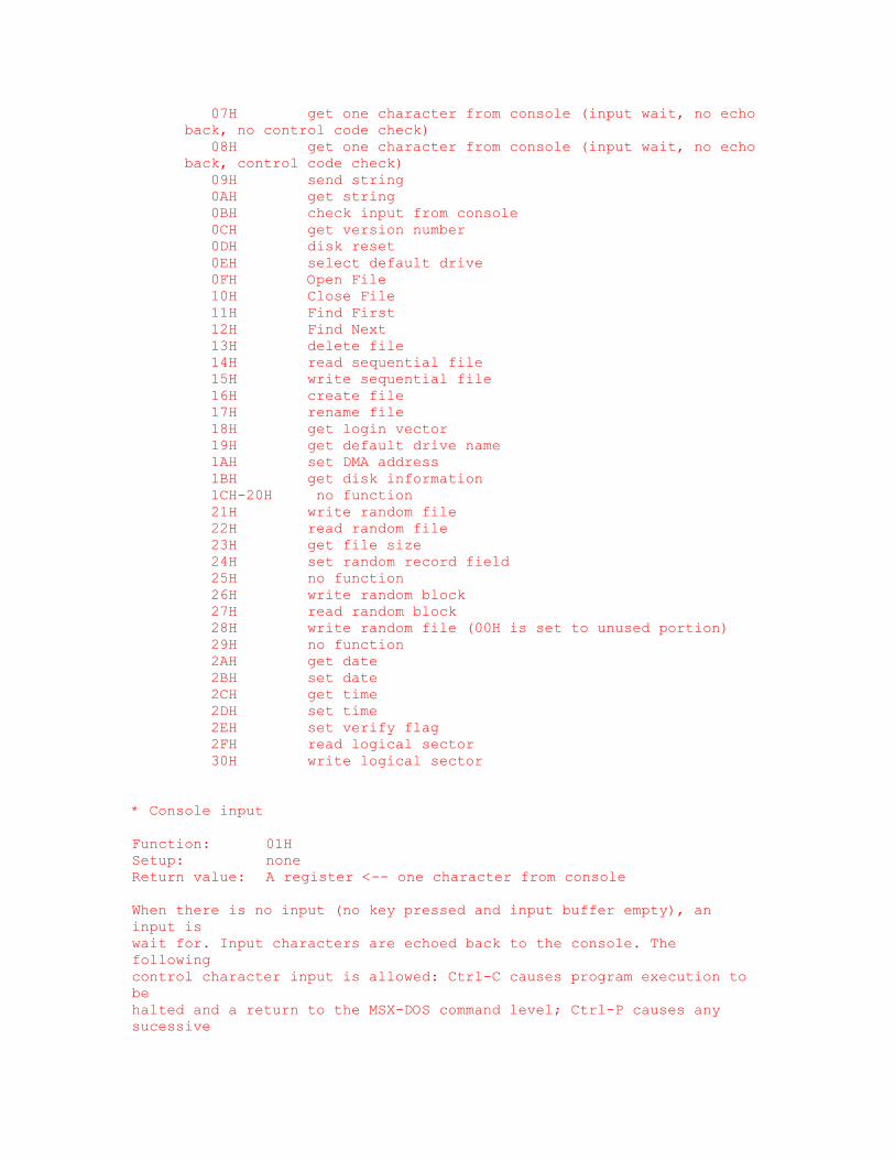
07H get one character from console (input wait, no echo back, no control code check) 08H get one character from console (input wait, no echo back, control code check) 09H send string 0AH get string 0BH check input from console 0CH get version number 0DH disk reset 0EH select default drive 0FH Open File 10H Close File 11H Find First 12H Find Next 13H delete file 14H read sequential file 15H write sequential file 16H create file 17H rename file 18H get login vector 19H get default drive name 1AH set DMA address 1BH get disk information 1CH-20H no function 21H write random file 22H read random file 23H get file size 24H set random record field 25H no function 26H write random block 27H read random block 28H write random file (00H is set to unused portion) 29H no function 2AH get date 2BH set date 2CH get time 2DH set time 2EH set verify flag 2FH read logical sector 30H write logical sector
* Console input Function: 01H Setup: none Return value: A register <-- one character from console When there is no input (no key pressed and input buffer empty), an input is wait for. Input characters are echoed back to the console. The following control character input is allowed: Ctrl-C causes program execution to be halted and a return to the MSX-DOS command level; Ctrl-P causes any sucessive
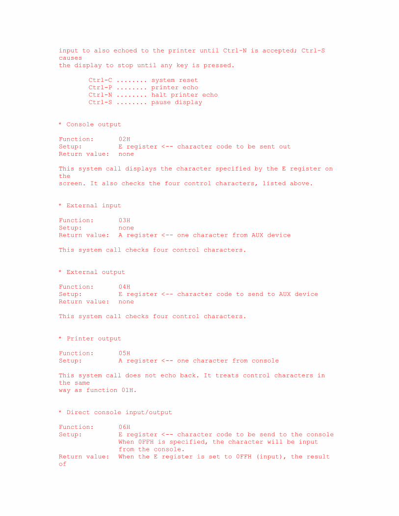
input to also echoed to the printer until Ctrl-N is accepted; Ctrl-S causes the display to stop until any key is pressed. Ctrl-C ........ system reset Ctrl-P ........ printer echo Ctrl-N ........ halt printer echo Ctrl-S ........ pause display * Console output Function: 02H Setup: E register <-- character code to be sent out Return value: none This system call displays the character specified by the E register on the screen. It also checks the four control characters, listed above. * External input Function: 03H Setup: none Return value: A register <-- one character from AUX device This system call checks four control characters. * External output Function: 04H Setup: E register <-- character code to send to AUX device Return value: none This system call checks four control characters. * Printer output Function: 05H Setup: A register <-- one character from console This system call does not echo back. It treats control characters in the same way as function 01H. * Direct console input/output Function: 06H Setup: E register <-- character code to be send to the console When 0FFH is specified, the character will be input from the console. Return value: When the E register is set to 0FFH (input), the result of
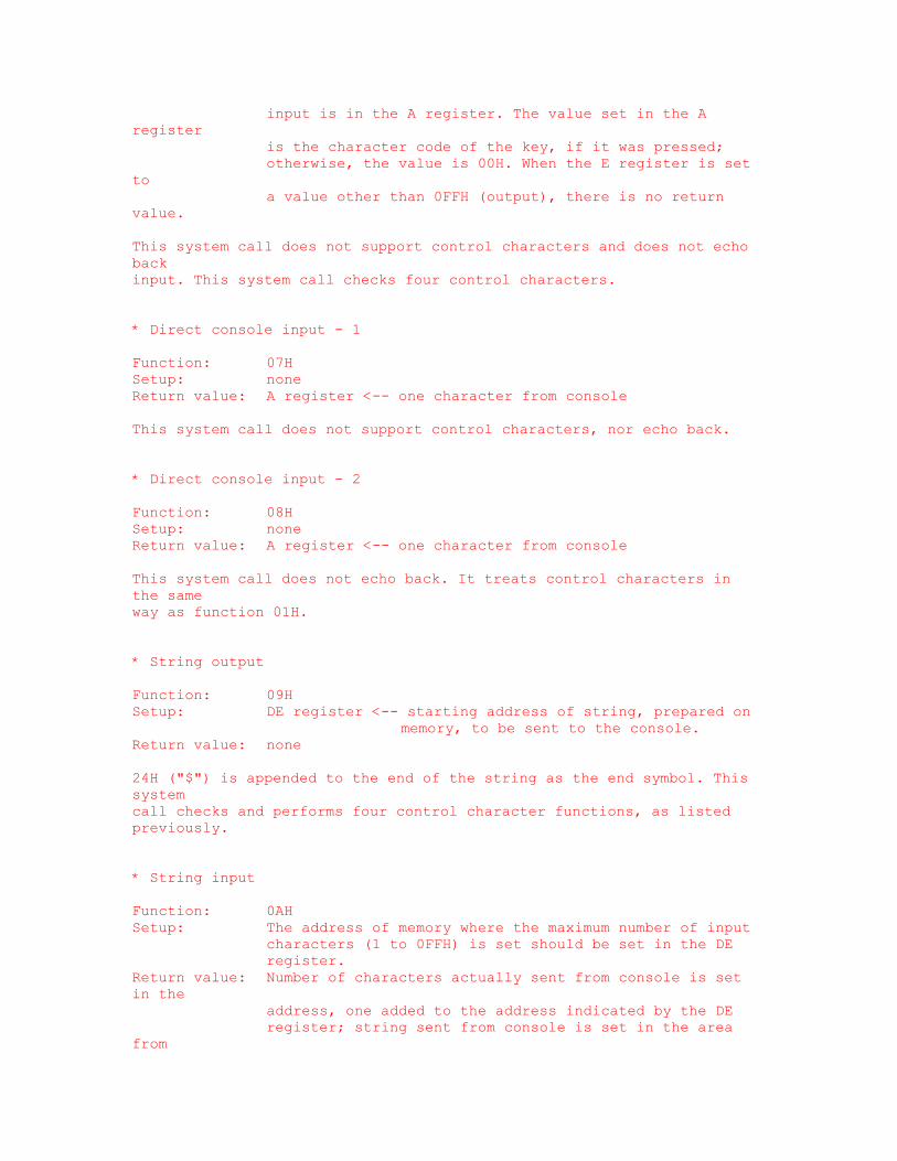
input is in the A register. The value set in the A register is the character code of the key, if it was pressed; otherwise, the value is 00H. When the E register is set to a value other than 0FFH (output), there is no return value. This system call does not support control characters and does not echo back input. This system call checks four control characters. * Direct console input - 1 Function: 07H Setup: none Return value: A register <-- one character from console This system call does not support control characters, nor echo back. * Direct console input - 2 Function: 08H Setup: none Return value: A register <-- one character from console This system call does not echo back. It treats control characters in the same way as function 01H. * String output Function: 09H Setup: DE register <-- starting address of string, prepared on memory, to be sent to the console. Return value: none 24H ("$") is appended to the end of the string as the end symbol. This system call checks and performs four control character functions, as listed previously. * String input Function: 0AH Setup: The address of memory where the maximum number of input characters (1 to 0FFH) is set should be set in the DE register. Return value: Number of characters actually sent from console is set in the address, one added to the address indicated by the DE register; string sent from console is set in the area from
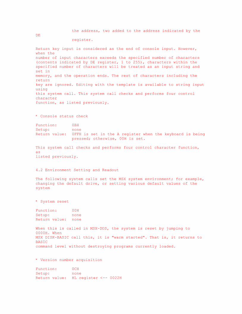
the address, two added to the address indicated by the DE register. Return key input is considered as the end of console input. However, when the number of input characters exceeds the specified number of characters (contents indicated by DE register, 1 to 255), characters within the specified number of characters will be treated as an input string and set in memory, and the operation ends. The rest of characters including the return key are ignored. Editing with the template is available to string input using this system call. This system call checks and performs four control character function, as listed previously. * Console status check Function: 0BH Setup: none Return value: 0FFH is set in the A register when the keyboard is being pressed; otherwise, 00H is set. This system call checks and performs four control character function, as listed previously. 4.2 Environment Setting and Readout The following system calls set the MSX system environment; for example, changing the default drive, or setting various default values of the system * System reset Function: 00H Setup: none Return value: none When this is called in MSX-DOS, the system is reset by jumping to 0000H. When MSX DISK-BASIC call this, it is "warm started". That is, it returns to BASIC command level without destroying programs currently loaded. * Version number acquisition Function: 0CH Setup: none Return value: HL register <-- 0022H
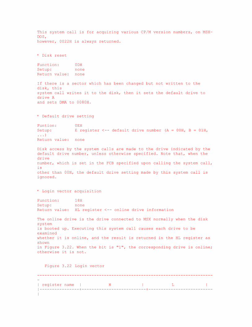
This system call is for acquiring various CP/M version numbers, on MSX-DOS, however, 0022H is always returned. * Disk reset Function: 0DH Setup: none Return value: none If there is a sector which has been changed but not written to the disk, this system call writes it to the disk, then it sets the default drive to drive A and sets DMA to 0080H. * Default drive setting Funtion: 0EH Setup: E register <-- default drive number (A = 00H, B = 01H, ...) Return value: none Disk access by the system calls are made to the drive indicated by the default drive number, unless otherwise specified. Note that, when the drive number, which is set in the FCB specified upon calling the system call, is other than 00H, the default drive setting made by this system call is ignored. * Login vector acquisition Function: 18H Setup: none Return value: HL register <-- online drive information The online drive is the drive connected to MSX normally when the disk system is booted up. Executing this system call causes each drive to be examined whether it is online, and the result is returned in the HL register as shown in Figure 3.22. When the bit is "1", the corresponding drive is online; otherwise it is not. Figure 3.22 Login vector ------------------------------------------------------------------------ | register name | H | L | |----------------+--------------------------+--------------------------|
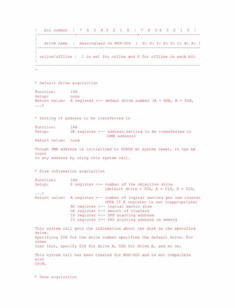
| bit number | 7 6 5 4 3 2 1 0 | 7 6 5 4 3 2 1 0 | |----------------+--------------------------+--------------------------| | drive name | meaningless on MSX-DOS | H: G: F: E: D: C: B: A: | |----------------+-----------------------------------------------------| | online/offline | 1 is set for online and 0 for offline in each bit | ------------------------------------------------------------------------ * Default drive acquisition Function: 19H Setup: none Return value: A register <-- defaut drive number (A = 00H, B = 01H, ...) * Setting of address to be transferred to Function: 1AH Setup: DE register <-- address setting to be transferred to (DMA address) Return value: none Though DMA address is initialized to 0080H at system reset, it can be reset to any address by using this system call. * Disk information acquisition Function: 1BH Setup: E register <-- number of the objective drive (default drive = 00H, A = 01H, B = 02H, ...) Return value: A register <-- number of logical sectors per one cluster (FFH if E register is set inappropriate) BC register <-- logical sector size DE register <-- amount of clusters IX register <-- DPB starting address IY register <-- FAT starting address on memory This system call gets the information about the disk in the specified drive. Specifying 00H for the drive number specifies the default drive. For other than that, specify 01H for drive A, 02H for drive B, and so on. This system call has been created for MSX-DOS and is not compatible with CP/M. * Date acquisition

Function: 2AH Setup: none Return value: HL register <-- year D register <-- month E register <-- day of month A register <-- day of week This system call has been created for MSX-DOS and is not compatible with CP/M. * Date setting Function: 2BH Setup: HL register <-- year D register <-- month E register <-- day of month Return value: A indicates whether the system call has done succesfully. If successful, the A register is set to 00H; otherwise, 0FFH. This system call has been created for MSX-DOS and is not compatible with CP/M. * Time acquisition Function: 2CH Setup: none Return value: H register <-- hour L register <-- minute D register <-- second E register <-- 1/100 second This system call has been created for MSX-DOS and is not compatible with CP/M. * Time setting Function: 2DH Setup: H register <-- hour L register <-- minute D register <-- second E register <-- 1/100 second Return value: If successful, the A register is set to 00H; otherwise, 0FFH This system call has been created for MSX-DOS and is not compatible with CP/M.
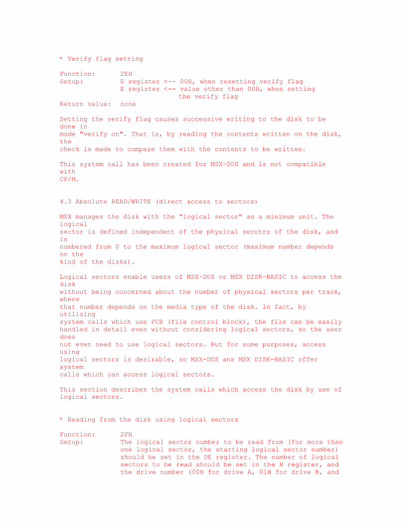
* Verify flag setting Function: 2EH Setup: E register <-- 00H, when resetting verify flag E register <-- value other than 00H, when setting the verify flag Return value: none Setting the verify flag causes successive writing to the disk to be done in mode "verify on". That is, by reading the contents written on the disk, the check is made to compare them with the contents to be written. This system call has been created for MSX-DOS and is not compatible with CP/M. 4.3 Absolute READ/WRITE (direct access to sectors) MSX manages the disk with the "logical sector" as a minimum unit. The logical sector is defined independent of the physical secotrs of the disk, and is numbered from 0 to the maximum logical sector (maximum number depends on the kind of the disks). Logical sectors enable users of MSX-DOS or MSX DISK-BASIC to access the disk without being concerned about the number of physical sectors per track, where that number depends on the media type of the disk. In fact, by utilizing system calls which use FCB (file control block), the file can be easily handled in detail even without considering logical sectors, so the user does not even need to use logical sectors. But for some purposes, access using logical sectors is desirable, so MSX-DOS ans MSX DISK-BASIC offer system calls which can access logical sectors. This section describes the system calls which access the disk by use of logical sectors. * Reading from the disk using logical sectors Function: 2FH Setup: The logical sector number to be read from (for more than one logical sector, the starting logical sector number) should be set in the DE register. The number of logical sectors to be read should be set in the H register, and the drive number (00H for drive A, 01H for drive B, and
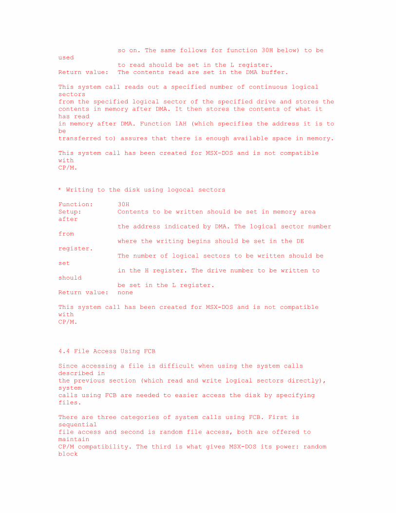
so on. The same follows for function 30H below) to be used to read should be set in the L register. Return value: The contents read are set in the DMA buffer. This system call reads out a specified number of continuous logical sectors from the specified logical sector of the specified drive and stores the contents in memory after DMA. It then stores the contents of what it has read in memory after DMA. Function 1AH (which specifies the address it is to be transferred to) assures that there is enough available space in memory. This system call has been created for MSX-DOS and is not compatible with CP/M. * Writing to the disk using logocal sectors Function: 30H Setup: Contents to be written should be set in memory area after the address indicated by DMA. The logical sector number from where the writing begins should be set in the DE register. The number of logical sectors to be written should be set in the H register. The drive number to be written to should be set in the L register. Return value: none This system call has been created for MSX-DOS and is not compatible with CP/M. 4.4 File Access Using FCB Since accessing a file is difficult when using the system calls described in the previous section (which read and write logical sectors directly), system calls using FCB are needed to easier access the disk by specifying files. There are three categories of system calls using FCB. First is sequential file access and second is random file access, both are offered to maintain CP/M compatibility. The third is what gives MSX-DOS its power: random block

access. This method is not available in CP/M. Random block access has the following features: * Any record size can be specified * Random access can be made to multiple records * File size can be controlled in bytes This section describes system calls for file access using FCB, including random block access. Note that the following three functions do not work correctly when FCB is in the address range 4000H to 7FFFH: 1. Function call 11H 2. Function call 12H 3. Input/output for devices (CON, PRN, NUL, AUX) * Opening files Function: 0FH Setup: DE register <-- starting address of FCB which is not opened Return value: 00H is set in the A register when a file is opened succeessfully; otherwise 0FFH is set. When a file is opened successfully, each field of the FCB is set. When 00H is specified for a drive number, the default drive set by function 0EH (default drive setting) is used. To open a file on another drive, specify 01H for drive A, 02H for drive B and so on. When a file is opened by this system call, all FCB fields except record size, current block, current record, and random record are set using information from the directory area on the disk. Fields which are not set should be set by the user after executing this system call, if needed. The state that each field of FCB is set is "the state that file is opened" when using system calls using FCB, and, in this case, system calls which access the file using FCB, described below, can be used. * Closing files Function: 10H Setup: DE register <-- starting address of opened FCB Return value: 00H is set in the A register when file is closed scuccessfully; otherwise, 0FFH is set.
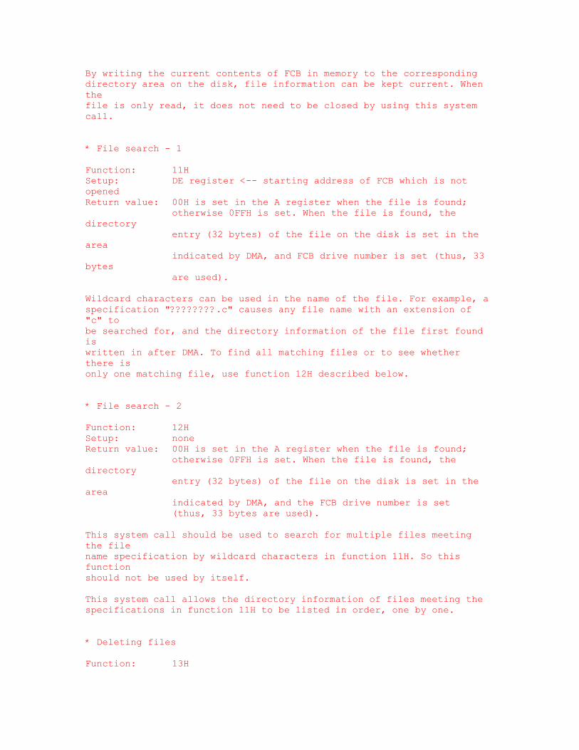
By writing the current contents of FCB in memory to the corresponding directory area on the disk, file information can be kept current. When the file is only read, it does not need to be closed by using this system call. * File search - 1 Function: 11H Setup: DE register <-- starting address of FCB which is not opened Return value: 00H is set in the A register when the file is found; otherwise 0FFH is set. When the file is found, the directory entry (32 bytes) of the file on the disk is set in the area indicated by DMA, and FCB drive number is set (thus, 33 bytes are used). Wildcard characters can be used in the name of the file. For example, a specification "????????.c" causes any file name with an extension of "c" to be searched for, and the directory information of the file first found is written in after DMA. To find all matching files or to see whether there is only one matching file, use function 12H described below. * File search - 2 Function: 12H Setup: none Return value: 00H is set in the A register when the file is found; otherwise 0FFH is set. When the file is found, the directory entry (32 bytes) of the file on the disk is set in the area indicated by DMA, and the FCB drive number is set (thus, 33 bytes are used). This system call should be used to search for multiple files meeting the file name specification by wildcard characters in function 11H. So this function should not be used by itself. This system call allows the directory information of files meeting the specifications in function 11H to be listed in order, one by one. * Deleting files Function: 13H

Setup: DE register <-- starting address of FCB which is not opened Return value: 00H is set in the A register when file is successfully deleted., otherwise 0FFH is set. Using wildcard characters for the file name may cause more than one file to be deleted. Exercise caution when using wildcards to delete files. * Sequential readout Function: 14H Setup: DE register <-- starting address of opened FCB FCB current block <-- starting block for readout FCB current record <-- starting record for readout Return value: 00H is set in the A register when readout is successful; otherwise 01H is set. When successful, one record which has been read is set in the area indicated by DMA. The FCB current block and record will be updated automatically after the readout. That is, in successive readouts, the current block and record do not need to be set. The record size for readout is fixed at 128 bytes. * Sequential writing to the disk Function: 15H Setup: DE register <-- starting address of opened FCB FCB current block <-- starting block for writing FCB current record <-- starting record for writing 128 bytes starting from DMA <-- data to be written Return value: 00H is set in the A register when writing is successful; otherwise 01H is set. The FCB current block and record will be updated automatically after the readout. * Creating files Function: 16H Setup: DE register <-- starting address of FCB which is not opened Retu4rn value: 00H is set in the A register when the file is created successfully; otherwise 0FFH is set. The record size, current block and record, and the random record of the FCB should be set after executing this system call. * Renaming files
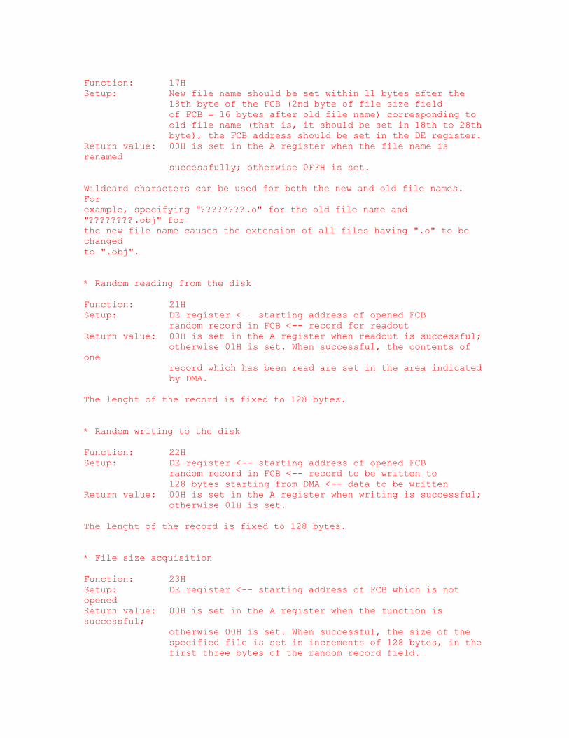
Function: 17H Setup: New file name should be set within 11 bytes after the 18th byte of the FCB (2nd byte of file size field of FCB = 16 bytes after old file name) corresponding to old file name (that is, it should be set in 18th to 28th byte), the FCB address should be set in the DE register. Return value: 00H is set in the A register when the file name is renamed successfully; otherwise 0FFH is set. Wildcard characters can be used for both the new and old file names. For example, specifying "????????.o" for the old file name and "????????.obj" for the new file name causes the extension of all files having ".o" to be changed to ".obj". * Random reading from the disk Function: 21H Setup: DE register <-- starting address of opened FCB random record in FCB <-- record for readout Return value: 00H is set in the A register when readout is successful; otherwise 01H is set. When successful, the contents of one record which has been read are set in the area indicated by DMA. The lenght of the record is fixed to 128 bytes. * Random writing to the disk Function: 22H Setup: DE register <-- starting address of opened FCB random record in FCB <-- record to be written to 128 bytes starting from DMA <-- data to be written Return value: 00H is set in the A register when writing is successful; otherwise 01H is set. The lenght of the record is fixed to 128 bytes. * File size acquisition Function: 23H Setup: DE register <-- starting address of FCB which is not opened Return value: 00H is set in the A register when the function is successful; otherwise 00H is set. When successful, the size of the specified file is set in increments of 128 bytes, in the first three bytes of the random record field.
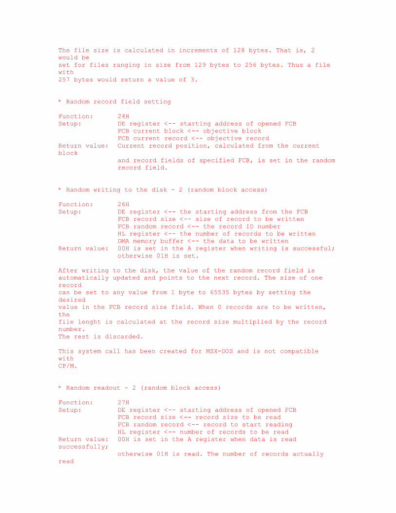
The file size is calculated in increments of 128 bytes. That is, 2 would be set for files ranging in size from 129 bytes to 256 bytes. Thus a file with 257 bytes would return a value of 3. * Random record field setting Function: 24H Setup: DE register <-- starting address of opened FCB FCB current block <-- objective block FCB current record <-- objective record Return value: Current record position, calculated from the current block and record fields of specified FCB, is set in the random record field. * Random writing to the disk - 2 (random block access) Function: 26H Setup: DE register <-- the starting address from the FCB FCB record size <-- size of record to be written FCB random record <-- the record ID number HL register <-- the number of records to be written DMA memory buffer <-- the data to be written Return value: 00H is set in the A register when writing is successful; otherwise 01H is set. After writing to the disk, the value of the random record field is automatically updated and points to the next record. The size of one record can be set to any value from 1 byte to 65535 bytes by setting the desired value in the FCB record size field. When 0 records are to be written, the file lenght is calculated at the record size multiplied by the record number. The rest is discarded. This system call has been created for MSX-DOS and is not compatible with CP/M. * Random readout - 2 (random block access) Function: 27H Setup: DE register <-- starting address of opened FCB FCB record size <-- record size to be read FCB random record <-- record to start reading HL register <-- number of records to be read Return value: 00H is set in the A register when data is read successfully; otherwise 01H is read. The number of records actually read
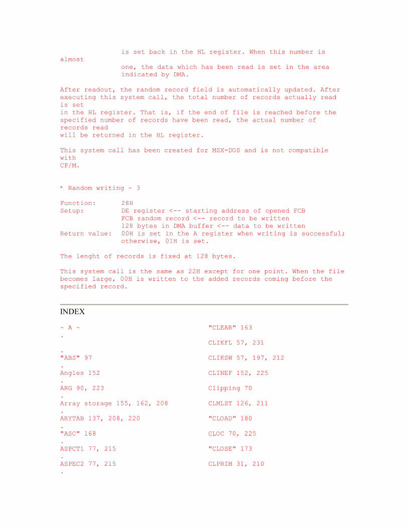
is set back in the HL register. When this number is almost one, the data which has been read is set in the area indicated by DMA. After readout, the random record field is automatically updated. After executing this system call, the total number of records actually read is set in the HL register. That is, if the end of file is reached before the specified number of records have been read, the actual number of records read will be returned in the HL register. This system call has been created for MSX-DOS and is not compatible with CP/M. * Random writing - 3 Function: 28H Setup: DE register <-- starting address of opened FCB FCB random record <-- record to be written 128 bytes in DMA buffer <-- data to be written Return value: 00H is set in the A register when writing is successful; otherwise, 01H is set. The lenght of records is fixed at 128 bytes. This system call is the same as 22H except for one point. When the file becomes large, 00H is written to the added records coming before the specified record.
INDEX - A - "CLEAR" 163 . CLIKFL 57, 231 . "ABS" 97 CLIKSW 57, 197, 212 . Angles 152 CLINEF 152, 225 . ARG 90, 223 Clipping 70 . Array storage 155, 162, 208 CLMLST 126, 211 . ARYTAB 137, 208, 220 "CLOAD" 180 . "ASC" 168 CLOC 70, 225 . ASPCT1 77, 215 "CLOSE" 173 . ASPEC2 77, 215 CLPRIM 31, 210 .

ASPECT 150, 225 "CLS" 41 . "ATN" 93 CMASK 70, 225 . ATRBAS 34, 225 "CMD" 202 . ATRBYT 69, 72, 76, 144, 214 CNPNTS 150, 225 . "ATTR$" 203 CNSDFG 49, 212 . AUTFLG 116, 219 Coincidence 9, 52 . AUTINC 116, 219 "COLOR" 197 . AUTLIN 116, 219 Colours 12, 39, 40, 77 . "AUTO" 125 CONLO 121, 217 . Control codes 44 . - B - CONSAV 121, 217 . "CONT" 162 . BAKCLR 39, 213 CONTXT 121, 217 . "BASE" 200, 201 CONTYP 121, 217 . BASROM 32, 86, 230 Coordinates, graphic 70, 143 . Baud rate 79, 197 Coordinates, text 42, 47, 51 . BDRATR 77, 235 "COPY" 202 . BDRCLR 40, 213 "COS" 92 . "BEEP" 60 CPCNT8 152, 226 . "BIN$" 165 CPLOTF 150, 226 . "BLOAD" 177 Crash 30 . BOTTOM 204, 232 CRCSUM 151, 226 . Boundary inflections 148 CRTCNT 47, 51, 211 . "BSAVE" 177 CS1200 197, 214 . BUF 85, 127, 176, 216 CS2400 197, 214 . "CSAVE" 179 . - C - CSAVEA 78, 149, 226 . CSAVEM 78, 149, 226 .
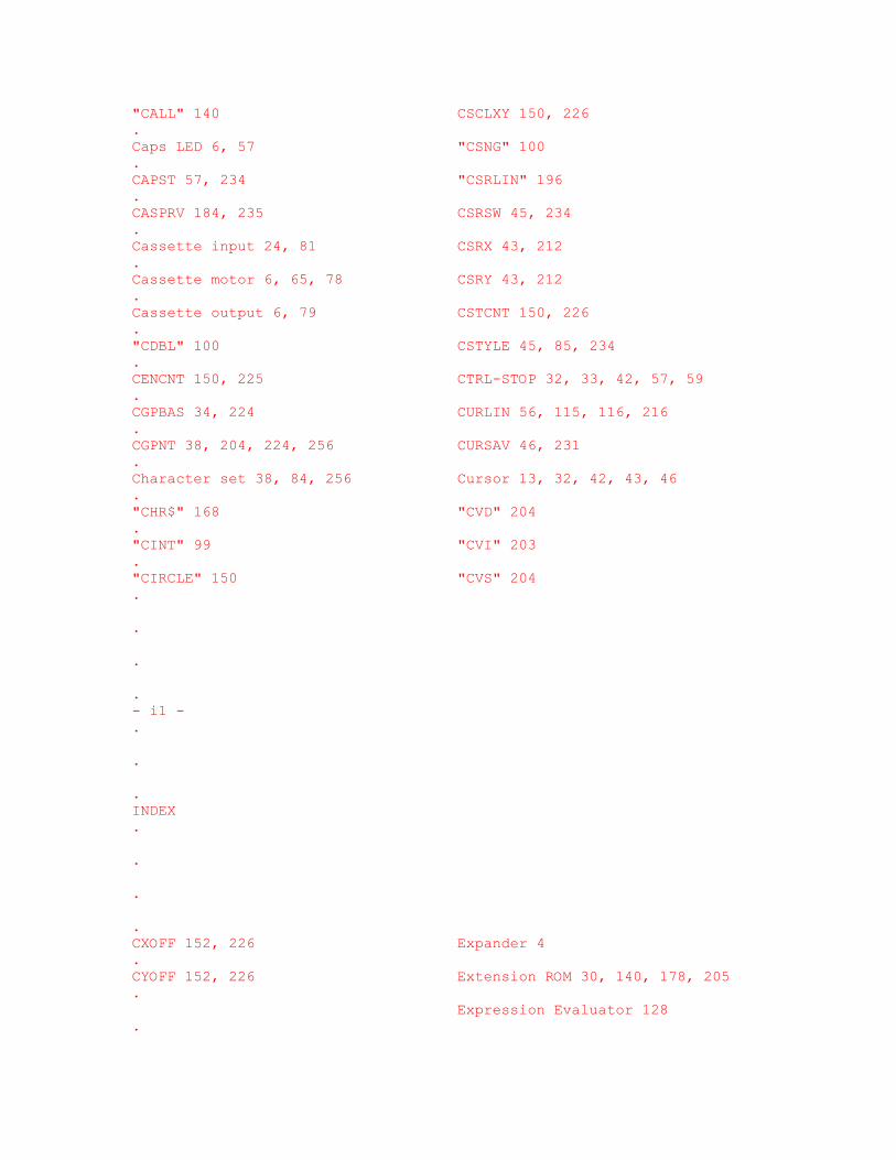
"CALL" 140 CSCLXY 150, 226 . Caps LED 6, 57 "CSNG" 100 . CAPST 57, 234 "CSRLIN" 196 . CASPRV 184, 235 CSRSW 45, 234 . Cassette input 24, 81 CSRX 43, 212 . Cassette motor 6, 65, 78 CSRY 43, 212 . Cassette output 6, 79 CSTCNT 150, 226 . "CDBL" 100 CSTYLE 45, 85, 234 . CENCNT 150, 225 CTRL-STOP 32, 33, 42, 57, 59 . CGPBAS 34, 224 CURLIN 56, 115, 116, 216 . CGPNT 38, 204, 224, 256 CURSAV 46, 231 . Character set 38, 84, 256 Cursor 13, 32, 42, 43, 46 . "CHR$" 168 "CVD" 204 . "CINT" 99 "CVI" 203 . "CIRCLE" 150 "CVS" 204 . . . . - i1 - . . . INDEX . . . . CXOFF 152, 226 Expander 4 . CYOFF 152, 226 Extension ROM 30, 140, 178, 205 . Expression Evaluator 128 .
- D - EXPTBL 5, 32, 236 . . DAC 90, 223 - F - . "DATA" 123 . Data areas 26 Factor Evaluator 129 . DATLIN 115, 128, 218 FBUFFR 106, 137, 222 . DATPTR 161, 220 "FIELD" 203 . Dead key 56, 58 File Control Block 66, 209 . "DEFDBL" 121 "FILES" 173 . "DEFFN" 134 Filespec 171 . "DEFINT" 121 FILNAM 171, 180, 224 . "DEFSNG" 121 FILNM2 181, 224 . "DEFSTR" 12I FILTAB 208, 223 . DEFTBL 121, 221 "FIX" 101 . "DEFUSR" 134 FLGINP 127, 219 . "DELETE" 137 "FN" 134 . Dequeueing 60 FNKFLG 56, 231 . DEVICE 142, 237 FNKSTR 65, 224 . Device 140, 171, 178 "FOR" 119 . "DIM" 155 FORCLR 40, 213 . DIMFLG 155, 217 "FPOS" 175 . DOT 115, 219 "FRE" 171 . "DRAW" 153 FRETOP 159, 208, 218 . DRWANG 154, 235 FSTPOS 84, 88, 230 . DRWFLG 154, 235 FUNACT 159, 222 . DRWSCL 154, 235 Function addresses 110, 130 . "DSKF" 202 Function key display 49, 53 . "DSKI$" 203 Function keys 56, 58, 65 .
"DSKO$" 202 . - G - . - E - . "GET" 193 . Editor 84 GETPNT 33, 59, 214 . Edit keys 85 "GOSUB" 122 . "ELSE" 123, 125 "GOTO" 123 . "END" 161 Graphic characters 42 . ENDFOR 119, 218 Graphic output 69 . ENSTOP 53, 230 GRPACX 69, 143, 235 . "EOF" 175 GRPACY 69, 143, 235 . "ERASE" 162 GRPATR 36, 212 . "ERL" 130 GRPHED 42, 234 . "ERR" 130 GRPNAM 36, 212 . ERRFLG 115, 130, 215 GRPPAT 36, 212 . ERRLIN 115, 125, 130, 219 GXPOS 144, 235 . "ERROR" 125 GYPOS 144, 235 . Error generators 115, 176 . Error handler 115 - H - . Error messages 113 . ERRTXT 115, 125, 220 HEADER 79, 215 . ESCCNT 43, 234 "HEX$" 165 . "EXP" 94 HIMEM 163, 204, 206, 232 . . . . - i2 - . .

. INDEX . . . . Hooks 30, 204, 237 Links 117 . LINL32 34, 211 . - I - LINL40 34, 211 . LINLEN 34, 211 . ID Bytes A0 LINTTB 39, 84, 230 . "IF" 125 LINWRK 46, 232 . "INKEY$" 187 "LIST" 137 . "INP" 114 "LLIST" 136 . "INPUT" 127 "LOAD" 172 . "INPUT$" 174 "LOC" 174 . Input, keyboard 53, 59 "LOCATE" 193 . INSFLG 85, 234 "LOF" 174 . "INSTR" 170 "LOG" 93 . "INT" 101 LOWLIM 81, 233 . INTCNT 52, 233 "LPOS" 132 . Interrupt mode 32 "LPRINT" 125 . Interrupts 9, 52, 56, 161 LPTPOS 83, 125, 132, 215 . "INTERVAL" 194 "LSET" 203 . INTFLG 32, 57, 233 . INTVAL 52, 233 - M - . I/O Buffer 66, 125, 130, 171 . I/O Dispatcher 178 Macro parser 142 . "IPL" 202 Mainloop 116 .
Math constants 97 . - J - Math operators 112 . MAXDEL 147, 225 . Japanese 4, 13, 25, 26, 58, 88, MAXFIL 171, 223 . 211, 234 "MAXFILES" 206 . JIFFY 52, 196, 233 MAXUPD 147, 213 . Joystick 24, 52, 63 MCLFLG 142, 188, 227 . MCLLEN 142, 188, 229 . - K - MCLPTR 142, 188, 229 . MCLTAB 142, 188, 227 . KANAMD 33, 234 MEMSIZ 159, 163, 208, 217 . KANAST 58, 234 "MERGE" 172 . Kansas City 79 "MID$" 169, 170 . KBUF 116, 118, 216 MINDEL 147, 225 . "KEY" 195 MINUPD 147, 213 . Keyboard 5, 53, 55, 66 "MKD$" 203 . KEYBUF 33, 231 "MKI$" 203 . Key click 6, 57, 58 "MKS$" 203 . Key numbers 54 MLTATR 36, 212 . Keywords, BASIC 110 MLTNAM 36, 212 . "KILL" 202 MLTPAT 36, 212 . "MOTOR" 187 . - L - MOVCNT 149, 227 . MSX2 228, 239, 240 . "LEFT$" 169 MSX2+ 239, 240 . "LEN" 168 MUSICF 52, 62, 229 . "LET" 123 Music packet 61, 193 . "LFILES" 173 .
"LINE" 145 - N - . "LINE INPUT" 126 . Line numbers 117, 118, 119, 122 NAMBAS 34, 224 . . . . - i3 - . . . INDEX . . . . "NAME" 202 Printer 33, 41, 83 . "NEW" 159 PRMLEN 159, 221 . NEWKEY 53, 231 PRMLN2 159, 222 . Newton-Raphson 93 PRMSTK 159, 221 . "NEXT" 164 PROCNM 140, 237 . NLONLY 159, 224 Program storage 117, 208 . NOFUNS 135, 156, 222 PRSCNT 188 228 . NTMSXP 83, 197, 216 PRTFLG 83, i25, 215 . NULBUF 208, 223 "PSET" 144 . Numeric output 106 PSG 21, 33, 34, 60, 190 . Numeric types 104 PTRFIL 66, 125, 223 . "PUT" 193 . - O - PUTPNT 33, 59, 214 . . "OCT$" 164 - Q - .
OLDKEY 33, 53, 231 . OLDLIN 115, 162, 220 QUEBAK 68, 228 . OLDSCR 34, 136, 234 QUETAB 34, 67, 228 . OLDTXT 60, 115, 159, 162, 220 Queue 60, 67, 68, 189 . "ON" 124 QUEUEN 62, 229 . ONEFLG 124, 159, 220 QUEUES 68, 214 . ONELIN 115, 124, 159, 220 . ONGSBF 56, 160, 231 - R - . "OPEN" 172 . "OUT" 114 R800 244 . Output, Interpreter 82 RDPRIM 30 210 . Output, screen 43, 69 "READ" 104, 115, 127, 128, 175, 219 . "REM" 123 . - P - "RENUM" 138 . REPCNT 53, 214 . "PAD" 197 "RESTORE" 161 . Paddle 25, 64 "RESUME" 124 . PADX 65, 233 "RETURN" 123 . PADY 65, 233 RG0SAV (till RG7SAV) 35, 212 . Page 3 RG8SAV (till RG27SAV) ? . "PAINT" 148 "RIGHT$" 169 . PARM1 135 156, 221 "RND" 94 . PARM2 135 222 RNDX 94, 159, 223 . PATBAS 34, 224 RS2IQ 228 . PATWRK 69, 232 "RSET" 203 . "PDL" 196 "RUN" 122 . "PEEK" 138 RUNBNF 177, 235 . "PLAY" 188, 196 Runloop 120 .
PLYCNT 62, 189, 229 . "POINT" 144 - S - . Pointers 118, 139 . "POKE" 138 "SAVE" 172 . Polynomial 95 SAVENT 179, 235 . "POS" 132 SAVSTK 115, 120, 159, 219 . Power-up 32, 204 SAVTXT 120, 219 . Precedence 112, 129 SCNCNT 52, 214 . "PRESET" 144 "SCREEN" 197 . Primary Slot 3, 30, 32, 66 SCRMOD 34, 136, 234 . "PRINT" 125 Secondary Slot 4, 30, 32, 239 . . . . - i4 - . . . INDEX . . . . "SET" 202 - U - . "SGN" 98 . "SIN" 92 "USR" 133 . SKPCNT 149, 227 USRTAB 133, 210 . Slot ID 29, 140, 205 . SLTATR 140, 205, 236 - V - . SLTTBL 32, 236 .
"SOUND" 188 "VAL" 169 . "SPACE$" 169 VALTYP 104, 217 . "SPRITE" 194, 197, 198 Variable storage 135, 155, 208 . Sprites 9, 18, 37, 199 "VARPTR" 130 . "SQR" 93 VARTAB 137, 208, 220 . Stack space 159 VCBA 34, 61, 67, 230 . Standard routines 26 "VDP" 199, 200 . Statement addresses 109, 136 VDP Address Register 8, 40 . STATFL 52, 213 VDP Mode Registers 9, 35 . "STICK" 196 VDP Modes 10, 13, 34, 41 . STKTOP 159, 163, 209, 217 VDP Status Register 9, 52, 65 . "STOP" 161, 194 VDP Timing 39 . "STR$" 165 "VPEEK" 201 . STREND 137, 208, 220 "VPOKE" 201 . "STRIG" 194, 196 VLZADR 115, 216 . "STRING$" 168 VLZDAT 115, 216 . String storage 133, 163, 166, 168 . SUBFLG 155, 218 - W - . "SWAP" 162 . SWPTMP 162, 222 "WAIT" 114 . Wait state 81 . - T - Warm start 53 . "WIDTH" 136 . T32ATR 34, 211 WINWID 81, 233 . T32CGP 34, 211 Workspace Area 32, 208 . T32NAM 34, 211 WRPRIM 30, 210 . T32PAT 34, 211 . "TAN" 93 - Z - .
TEMPPT 159, 218 . TEMPST 124, 218 Z80 Clock 81 . "TIME" 196 . Tokens 111, 117, 118, 121, 137 . Touchpad 25, 64 . TRCFLG 120, 222 . TRGFLG 52, 213 . "TROFF" 162 . "TRON" 162 . TRPTBL 32, 56, 160, 194, 232 . TTYPOS 43, 125, 132, 216 . turbo R 65, 239, 240 . TXTCGP 34, 211 . TXTNAM 34 211 . TXTTAB 117, 204, 208, 218 . Types 140 . . . . . . . - i5 -