the renard diamond project québec, canada feasibility...
TRANSCRIPT
The Renard Diamond Project Québec, Canada Feasibility Study NI 43-101 Technical Report December 29, 2011 Qualified Persons Mr Paul Bedell, P.Eng., Golder Associates Ltd. Ms Valérie J. Bertrand, géo., Golder Associates Ltd. Dr Richard Brummer, P.Eng., Itasca Consulting Canada Inc. Mr David Farrow, P.Geo., GeoStrat Consulting Services Inc. Mr Louis-Pierre Gignac, Eng.,G Mining Services Inc. Dr Lynton Gormely, P.Eng., AMEC Americas Limited Mr Ab Kroon, P.Eng., SNC-Lavalin Inc. Mr Martin Magnan, Eng., Roche ltée, Groupe-Conseil Mr Gary Taylor, P.Eng., AMEC Americas Limited Mr Pierre Therrien, ing., Genivar Inc.
Effective Date November 8, 2011

IMPORTANT NOTICE This report was prepared as a National Instrument 43-101 Technical Report for Stornoway Diamond Corporation (Stornoway). Portions of the Technical Report were authored by Qualified Persons employed by AMEC Americas Limited (AMEC) as identified in those Qualified Persons’ Certificates. The quality of information, conclusions, and estimates contained in those sections prepared by AMEC employed Qualified Persons is consistent with the level of effort involved in AMEC’ services, based on: i) information available at the time of preparation, ii) data supplied by outside sources, and iii) the assumptions, conditions, and qualifications set forth in this report. This report is intended for use subject to the terms and conditions of Stornoway’s contract with AMEC. Except for the purposes legislated under provincial securities laws, any other use of this report by any third party is at that party’s sole risk.

CERTIFICATE OF QUALIFIED PERSON
Paul Micheau Bedell
To accompany the report entitled “The Renard Diamond Project, Québec, Canada, Feasibility Study, NI 43-101 Technical Report” (the “Technical Report”), dated November 8, 2011, I, Paul M. Bedell, P.Eng., do hereby certify that:
1. I am an Associate and Senior Geotechnical Engineer employed at Golder Associates Ltd. located at 500-4260 Still Creek Drive, Burnaby, British Columbia, Canada.
2. Graduated with Bachelor of Engineering Science degree in Civil Engineering and a Master of Engineering Science from The University of Western Ontario in London, Ontario in 1994 and 1997, respectively.
3. I am a registered Professional Engineer in British Columbia (membership number 28511), Ontario (membership number 100026653), Saskatchewan (membership number 11859), and the Northwest Territories and Nunavut (membership number L1746).
4. I have worked as an engineer since my graduation from The University of Western Ontario. For the past 15 years I have been employed with Golder Associates Ltd. During this period I have fulfilled the role of engineer on mining projects directing and completing geotechnical engineering for mine waste management and soils. I currently hold the position of Associate, Senior Geotechnical Engineer.
5. I have read the definition of “qualified person” set out in National Instrument 43-101 (“NI 43-101) and certify that by reason of education, affiliation with a professional association (as defined in NI 43-101) and past relevant work experience, I fulfil the requirements to be a “qualified person” for the purpose of this NI 43-101.
6. I am responsible for Sections 10.4 (post 2010), 16.1, 18.1, 18.4, 20.3, 25 (PKC facility), and 26.3 of the Technical Report.
7. I visited the Renard Diamond Project property from September 29 to October 1, 2010, inclusive.
8. I am independent of Stornoway Diamond Corporation applying the test set out in Section 1.5 of the NI 43-101.
9. I have had no prior involvement with the property that is subject of the Technical Report.
10. As of the date of this certificate, to the best of my knowledge, information, and belief, that Sections 10.4 (post-2010 geotechnical), 16.1, 18.1, 18.4, 20.3, 25 (PKC facility), and 26.3 for which I am responsible in this technical report, contain all the scientific and technical information that is required to be disclosed to make this technical report not misleading.
“Signed and sealed”, Dated this 29th day of December 2011.
Paul M. Bedell, M.E.Sc., P.Eng. Associate, Senior Geotechnical Engineer Golder Associates Ltd.

CERTIFICATE OF QUALIFIED PERSON
Valérie Johanne Bertrand
To accompany the report entitled “The Renard Diamond Project, Québec, Canada, Feasibility Study, NI 43-101 Technical Report” (the “Technical Report”), dated November 8, 2011, I, Valérie J. Bertrand, géo., do hereby certify that:
1. I am an Associate and Senior Geochemist employed at Golder Associates Ltd. located at 32 Steacie Drive, Kanata Ontario. K2K 2A9, Canada.
2. I graduated with a Bachelor of Science degree in Geology from the University of Ottawa in Ottawa Ontario in 1991 and have a Master of Applied Science degree in Mining Engineering at the University of British Columbia in Vancouver BC which I obtained in 1999.
3. I am a registered Professional Geoscientist in Ontario (membership number 1458) and a member in good standing of l’Ordre des Géologues du Québec (membership number 1221).
4. I have worked as a geoscientist since my graduation from the University of Ottawa. For the past 12 years I have been employed with Golder Associates Limited. During this period I have fulfilled the role of geochemist on mining projects directing and completing environmental geochemistry investigations on mine wastes, soils and water. I currently hold the position of Associate, Senior Geochemist.
5. I have read the definition of “qualified person” set out in National Instrument 43-101 (“NI 43-101) and certify that by reason of education, affiliation with a professional association (as defined in NI 43-101) and past relevant work experience, I fulfil the requirements to be a “qualified person” for the purpose of this NI 43-101.
6. I am responsible for Section 20.2 of the Technical Report. 7. I visited the Renard Diamond Project property from September 29 to October 1, 2010,
inclusive. 8. I am independent of Stornoway Diamond Corporation applying the test set out in Section
1.5 of the NI 43-101. 9. I have had no prior involvement with the property that is subject of the Technical Report.
10. As of the date of this certificate, to the best of my knowledge, information and belief,
Sections 20.2, for which I am responsible for in this technical report, contains all the scientific and technical information that is required to be disclosed to make this technical report not misleading.
“Signed and sealed”, Dated this 29th day of December 2011.
Valérie J. Bertrand, géo. M.A.Sc. Associate, Senior Geochemist Golder Associates Ltd.

CERTIFICATE OF QUALIFIED PERSON Richard K. Brummer, PhD, Professional Engineer (Ontario)
Itasca Consulting Canada Incorporated, 166 Douglas Street
Sudbury, Ontario, P3E1G1 [email protected]
I, Richard K. Brummer, PhD, Professional Engineer (Ontario), am employed as Principal Geomechanics Engineer with Itasca Consulting Canada Incorporated. This certificate applies to the technical report entitled “The Renard Diamond Project, Québec, Canada, Feasibility Study, NI 43-101 Technical Report” dated November 8, 2011.
I am a member and “Designated Consulting Engineer” of Professional Engineers Ontario. I graduated with the degrees of Bachelor of Science in Engineering (cum laude) (1977), Master of Science in Engineering (1980), Bachelor of Commerce (Honours) (1990), all from the University of the Witwatersrand, Johannesburg, South Africa, and Doctor of Engineering (PhD) from the University of Johannesburg (formerly RAU) in 1988.
I have practiced my profession for 34 years. I have been directly involved in the design and evaluation of mining methods for over 100 underground and open pit mines in Africa, North and South America, Europe, Asia and Australia.
As a result of my experience and qualifications, I am a Qualified Person as defined in National Instrument 43–101 Standards of Disclosure for Mineral Projects (NI 43–101).
I have not visited Stornoway’s Renard site, but engineers under my direct supervision have visited the site.
I am responsible for Section 10.4 (pre-2010), Section 16.2, Section 16.3, Section 25 (rock mechanics) and Section 26.1 (rock mechanics) of the technical report titled “The Renard Diamond Project, Québec, Canada, Feasibility Study, NI 43-101 Technical Report” and dated November 8, 2011 the (“Technical Report”).
I am independent of Les Diamants Stornoway (Canada) Inc. as independence is described by Section 1.5 of NI 43–101.
I have been involved with the Renard Project on behalf of Les Diamants Stornoway (Canada) Inc. since October 2009.
I have read NI 43–101 and the sections of the technical report for which I am responsible have been prepared in compliance with that Instrument.
As of the date of this certificate, to the best of my knowledge, information and belief, the sections of the technical report for which I am responsible contain all scientific and technical information that is required to be disclosed to make those sections of the technical report not misleading.
“Signed and sealed”
Richard K. Brummer, PhD, P.Eng. Dated: December 29, 2011

CERTIFICATE OF QUALIFIED PERSON
Certificate of David Farrow
I, David Farrow, of Vancouver, British Columbia, Canada, do hereby certify that as an author of
this “The Renard Diamond Project, Québec, Canada, Feasibility Study, NI 43-101 Technical
Report”, dated, November 8, 2011, make the following statements:
1) I am a Geologist with GeoStrat Consulting Services Inc. of 40-4055 Indian River Drive,
North Vancouver, British Columbia, V7G 2R7, Canada
2) I am a graduate of the University of the Witwatersrand, Johannesburg, South Africa
(GDE (Geostatistics) 1998) and the University of Cape Town, Cape Town, South Africa
(B.Sc.(Hons) 1982).
3) I am a member in good standing of the Association of Professional Engineers and
Geoscientists of British Columbia (License # 33860). I am also a member in good standing
of The South African Council for Natural Science Professions (License # 400074/87).
4) I have practiced my profession continuously since graduation.
5) I have read the definition of “qualified person” set out in National Instrument 43-101 (N.I. 43-
101) and certify that, by reason of my education, affiliation with a professional association
(as defined in N.I. 43-101) and past relevant work experience, I fulfill the requirements to be
a “qualified person” for the purpose of N.I. 43-101.
6) My relevant experience with respect to Renard Deposits includes over 25 years in
exploration, mining geology and grade estimation in Canada and southern Africa.
7) I am responsible for the preparation of the section 1.2, 1.3, 1.4, 1.7, 4.1, 4.2, 4.3, 4.4, 4.5, 6,
7, 8, 9, 10.1, 10.2, 10.3, 10.5, 10.6, 12.1, 12.2, 14, 15.4.4 (Indicated Resources), 23 and 25
(Resources) of this technical report titled “The Renard Diamond Project, Québec, Canada,
Feasibility Study, NI 43-101 Technical Report”, dated November 8, 2011.
8) I visited the Property during the period, March 5 to March 9, 2009.
9) I was co-author of a previous NI 43-101 Preliminary Assessment report on the property,
dated May 5, 2010 and primary author of previous NI 43-101 compliant Mineral Resources
for the property, dated January 2010, and December 2010.
10) As of the date of this Certificate, to my knowledge, information and belief, the sections of
this Technical Report for which I am responsible contain all scientific and technical
information that is required to be disclosed to make the technical report not misleading.
11) I am independent of the Issuer as defined by Section 1.5 of the Instrument. I have read
National Instrument 43-101 and the sections for which I am responsible in this Technical
Report have been prepared in compliance with National Instrument 43-101 and Form
43-101F1.
“Signed and sealed”, dated this 29th day of December 2011 at North Vancouver, British
Columbia, Canada.
David Farrow, Pr.Sci.Nat. P.Geo.

CERTIFICATE OF QUALIFIED PERSON
I, Louis-Pierre Gignac, Eng., do hereby certify that :
1. I am a consulting mining engineer for G Mining Services Inc., 7900 Boul. Taschereau,
Edifice D, Suite 200, Brossard, Québec J4X 1C2;
2. I have graduated from McGill University, Canada with a B.Sc. In Mining Engineering in
1999, and from École Polytechnique de Montréal, Canada with a M.Sc.A. in Industrial
Engineering in 2002.
3. I am in good standing as a member of the Order of Engineers of Québec (#132995) and
I am a member of the Canadian Institute of Mining.
4. I have worked in the mining industry continuously since my graduation from university.
5. I have read the definition of “qualified person” set out in the National Instrument 43-101
(“NI 43-101”) and certify that as a result of my education, affiliation with a professional
association (as defined in NI 43-101) and past relevant work experience, I fulfill the
requirements to be a “qualified person” for the purposes of NI 43-101.
6. I am the author of sections 1.8 (OP), 1.9, 3.2, 15.1 (OP), 15.2, 15.4 (OP), 15.5 (OP), 16.0 (OP), 16.4, 16.6 (OP), 18.5, 19, 22, 25 (OP/financial analysis, road contract), and 26.1 (OP) of this Technical Report entitled “The Renard Diamond Project, Québec, Canada, Feasibility Study, NI 43-101 Technical Report” dated November 8, 2011;
7. I have visited the site on June 15, 2010; 8. I have no personal knowledge as of the date of this certificate of any material fact or
change, which is not reflected in this report; 9. Neither I, nor any affiliated entity of mine, is at present, under an agreement,
arrangement or understanding or expects to become, an insider, associate, affiliated entity or employee of Stornoway Diamond Corporation., or any associated or affiliated entities;
10. Neither I, nor any affiliated entity of mine, own, directly or indirectly, nor expect to receive, any interest in the properties or securities of Stornoway Diamond Corporation, or any associated or affiliated companies;
11. Neither I, nor any affiliated entity of mine, have earned the majority of our income during the preceding three years from Stornoway Diamond Corporation., or any associated or affiliated companies
12. I have read NI 43-101 and Form 43-101F1 and have prepared the technical report in compliance with NI 43-101 and Form 43-101F1; and have prepared the report in conformity with generally accepted Canadian mining industry practice, and as of the date of the certificate, to the best of my knowledge, information and belief, the technical report contains all scientific and technical information that is required to be disclosed to make the technical report not misleading.
“Signed and sealed”, dated at Brossard this 29th day of December 2011.
______________________
Louis-Pierre Gignac, Eng.
Mining Engineer, G Mining Services Inc.
Brossard, Qc, Canada

CERTIFICATE OF QUALIFIED PERSON
Lynton Gormely, Ph.D., P.Eng. AMEC Americas Limited
111 Dunsmuir Street, Suite 400 Vancouver, B.C. V6B 5W3
Tel (604) 664-3312 Fax (604) 669-9516
[email protected] I, Lynton Gormely, Ph.D., P.Eng., am employed as a Principal Process Engineer with AMEC
Americas Limited.
This certificate applies to the technical report entitled “The Renard Diamond Project, Québec,
Canada, Feasibility Study, NI 43-101 Technical Report” dated November 8, 2011.
I am a member of the Association of Professional Engineers and Geoscientists of British
Columbia, registration number 10005. I graduated from the University of British Columbia with a
Bachelor of Applied Science degree in 1968, and from the University of British Columbia with a
Ph.D. in Chemical Engineering in 1973.
I have practiced my profession for 38 years. I have been directly involved in process
engineering design and construction projects for the mining industry for the recovery of base
and precious metals. I have experience with the principles of the design of the metallurgical
testwork, the design of the process flow sheets, and the selection of the mineral processing
equipment, which is relevant to diamond processing.
As a result of my experience and qualifications, I am a Qualified Person as defined in National
Instrument 43–101 Standards of Disclosure for Mineral Projects (NI 43–101).
I have not visited the Renard property in northern Québec.
I am responsible for supervising the preparation of Sections 1.5, 11, 13, 17, 25 (processing) and
26.2 of “The Renard Diamond Project, Québec, Canada, Feasibility Study, NI 43-101 Technical
Report”.
I am independent of Stornoway Diamond Corporation as independence is described by Section
1.5 of NI 43–101.
I have had no previous involvement with the Renard Project.
I have read NI 43–101 and the sections of the technical report for which I am responsible have
been prepared in compliance with that Instrument.
As of the date of this certificate, to the best of my knowledge, information and belief, the
sections of the technical report for which I am responsible contain all scientific and technical
information that is required to be disclosed to make those sections of the technical report not
misleading.
“Signed and sealed”
Lynton Gormely, Ph.D., P.Eng.
Dated: December 29, 2011

CERTIFICATE OF QUALIFIED PERSON
A. S Kroon, Professional Engineer
I, A.S. Kroon, Naples Avenue, Brossard, Québec, Postal Code J4Y 1V8 (Tel: 450-676-4032) am
an independent Geological and Mining Consultant.
This certificate applies to the technical report entitled “The Renard Diamond Project, Québec,
Canada, Feasibility Study, NI 43-101 Technical Report” dated November 8, 2011 (hereinafter
the “Technical Report”).
I am a member of the Order of Professional Engineers of Québec and I am a member of the
CIMM (Canadian Institute of Mining and Metallurgy) since 1977. I graduated from the University
of Amsterdam in 1966 and hold an (equivalent of) Masters Degree in Geology. I have worked as
a geologist and mining engineer in the minerals industry for over 45 years since my graduation
from university. I worked as an exploration geologist, mining geologist and mining engineer in
Zambia from 1966 to 1971. From 1971 to 1973, I was the mine planning engineer for Texas-
Gulf in Timmins Ontario. From 1973 to 1976, I worked in New York City and was in charge of
an exploration and mining project in Greece. From 1976 to 1996, I worked for Kilborn (Québec)
and was in charge of feasibility studies and other technical studies for mining projects. When
Kilborn was purchased by SNC-Lavalin, I became a consultant for SNC-Lavalin for various
feasibility studies carried out by the company. I am also working for my own account. As a result
of my experience and qualifications, I am a Qualified Person as defined in National Instrument
43–101 Standards of Disclosure for Mineral Projects (NI 43–101).
I have not visited the Renard Property.
I am responsible for writing of the following sections or sub-sections: Section 18.2 - On Site
Infrastructures, Section 21.0 – Capital and Operating Costs, 24.1 – Project Execution Plan, 24.3
– Schedule, 24-4 – Risk Analysis and Management and related parts of Section 25.0 –
Interpretation and Conclusions of the Technical Report.
I am independent of Stornoway Diamond Corporation as independence is described by
Section 1.5 of NI 43–101.
I have had no previous involvement with the Renard mineral property.
I have read NI 43–101 and the sections of the Technical Report for which I am responsible and
am satisfied that the referenced sections have been prepared in compliance with that
Instrument.
As of the date of this certificate, to the best of my knowledge, information and belief, the
sections of the Technical Report for which I am responsible contain all scientific and technical
information that is required to be disclosed to make those sections of the Technical Report not
misleading.
“Signed and sealed”, dated December 29, 2011.
A.S. Kroon, Eng.

CERTIFICATE OF QUALIFIED PERSON I, Martin Magnan, Eng., do hereby certify that:
1. I am currently employed as Project Manager – Environment in the consulting firm:
Roche ltée, Groupe-Conseil 3075, ch. des Quatre-Bourgeois Bureau 300 Québec (Québec) G1W 4Y4 CANADA
2. I graduated from Laval University of Québec, Canada with a B. Sc. A. in Geological Engineering in 1990 and from Université du Québec à Chicoutimi of Québec, Canada with a M. Sc. A in Geology in 1994.
3. I am in good standing as a member of the Ordre des Ingénieurs du Québec (#126033).
4. I have practiced my profession continuously since my graduation.
5. I have read the definition of “qualified person” set out in the National Instrument 43-101
(“NI 43-101”) and certify that as a result of my education, affiliation with a professional association (as defined in NI 43-101) and past relevant work experience, I fulfill the requirements to be a “qualified person” for the purposes of NI 43-101.
6. I visited the Foxtrot Property on the 16th of November 2011.
7. I am responsible for sections 4.7, 4.8, 4.9, 5.0 to 5.5, 20.0, 20.1, 20.4, 20.5, 20.6 and
part of sections 25 and 26 of this Technical Report entitled “The Renard Diamond Project, Québec, Canada, Feasibility Study, NI 43-101 Technical Report” dated November 8, 2011.
8. As of the date of this certificate, to the best of my knowledge, information and belief, the
sections of the technical report for which I am responsible contain all scientific and technical information that is required to be disclosed to make those sections of the technical report not misleading.
9. I am independent of the issuer applying all of the tests in Section 1.5 of National
Instrument 43-101.
10. I have read national Instrument 43-101 and Form 43-101F1, and aforementioned sections of the Technical Report has been prepared in compliance with that instrument and form.
Prepared in Shawinigan, Québec, December 29, 2011 “Signed and sealed” ________________________ Martin Magnan Eng.

CERTIFICATE OF QUALIFIED PERSON
Gary Taylor, P.Eng. AMEC Americas Limited
301 – 121 Research Drive Saskatoon, Saskatchewan S7N 1K2
[email protected] I, Gary Taylor, P. Eng., am employed as Manager, Mining with AMEC Americas Limited.
This certificate applies to the technical report entitled “The Renard Diamond Project, Québec,
Canada, Feasibility Study, NI 43-101 Technical Report” dated November 8, 2011.
I am a member of The Association of Professional Engineers of Saskatchewan. I graduated
from Nova Scotia Technical University with a B.Eng., Mining Engineering, in 1969 and from
McGill University with a M. Eng., Mining Engineering, in 1972.
I have practiced my profession for forty years. I have been directly involved in mine design for
over twenty Prefeasibility and Feasibility Studies for underground projects over the last 22
years. These studies encompass diamond, gold and base metals as well as underground
projects located in northern Canada and throughout North and South America.
As a result of my experience and qualifications, I am a Qualified Person as defined in National
Instrument 43–101 Standards of Disclosure for Mineral Projects (NI 43–101).
I visited the Renard Project site on October 25, 2010.
I am responsible for Sections 1.1, 1.6, 1.8(UG), 1.10, 2.0 to 2.3, 3.0, 3.1, 3.3, 4.6, 5.6, 15.1(UG),
15.3,15.4(UG), 15.5 (UG), 16.0(UG), 16.5, 16.6(UG), 24.2, 25(UG), 26.1, and 27, of “The
Renard Diamond Project, Québec, Canada, Feasibility Study, NI 43-101 Technical Report”.
I am independent of Stornoway Diamond Corporation as independence is described by Section
1.5 of NI 43–101.
I have had no previous involvement with the Renard Project.
I have read NI 43–101 and the sections of the technical report for which I am responsible have
been prepared in compliance with that Instrument.
As of the date of this certificate, to the best of my knowledge, information and belief, the
sections of the technical report for which I am responsible contain all scientific and technical
information that is required to be disclosed to make those sections of the technical report not
misleading.
“Signed and sealed”
Gary Taylor, P. Eng., Dated: December 29, 2011

CERTIFICATE OF QUALIFIED PERSON
Pierre Therrien, Director - Transportation
GENIVAR Inc. 3, main Street North
Amos, Quebec J9T 2K5 [email protected]
I, Pierre Therrien, Director - Transportation, am employed as an engineer with GENIVAR Inc.
This certificate applies to the technical report entitled “The Renard Diamond Project, Québec,
Canada Feasibility Study, NI 43-101 Technical Report” dated November 8, 2011.
I am a member of the Ordre des ingénieur du Québec #106284. I graduated from Sherbrooke
University in 1991 with a Baccalaureat civil engineering.
I have practiced my profession for 20 years of years since graduation. I have not been directly
involved in the Project.
As a result of my experience and qualifications, I am a Qualified Person as defined in National
Instrument 43–101 Standards of Disclosure for Mineral Projects (NI 43–101).
I have not visited the Renard Property.
I am responsible for Section 18.3 of the Technical Report entitled “The Renard Diamond
Project, Quebec, Canada Feasibility Study, NI 43-101 Technical Report”.
I am independent of Stornoway Diamond Corporation, as independence is described by Section
1.5 of NI 43–101.
I have had no previous involvement with the Renard Project.
I have read NI 43–101 and the sections of the technical report for which I am responsible have
been prepared in compliance with that Instrument.
As of the date of this certificate, to the best of my knowledge, information and belief, the
sections of the technical report for which I am responsible contain all scientific and technical
information that is required to be disclosed to make those sections of the technical report not
misleading.
“Signed and sealed”, Dated December 29, 2011.
Pierre Therrien, ing. Director - Transportation

Stornoway Diamond Corporation - Renard Diamond Project Page i NI 43-101 Technical Report - December 29, 2011
TABLE OF CONTENTS
1.0 SUMMARY .................................................................................................................................... 1 Introduction .......................................................................................................................................... 1 1.1.
Property Location and Site Description................................................................................................ 1 1.2.
Property Ownership ............................................................................................................................. 1 1.3.
Geology and Mineralization ................................................................................................................. 2 1.4.
Mineral Processing and Metallurgical Testing ..................................................................................... 3 1.5.
Status of Project Development ............................................................................................................ 3 1.6.
Mineral Resources ............................................................................................................................... 4 1.7.
Mineral Reserves ................................................................................................................................. 6 1.8.
Financial Analysis ................................................................................................................................ 7 1.9.
Conclusions and Recommendations ................................................................................................... 7 1.10.
2.0 INTRODUCTION ........................................................................................................................... 8 Qualified Persons and Site Visits ....................................................................................................... 13 2.1.
Previous Technical Reports and References .................................................................................... 14 2.2.
Effective Date ..................................................................................................................................... 15 2.3.
3.0 RELIANCE ON OTHER EXPERTS ............................................................................................. 16 Mineral Tenure and Surface Rights ................................................................................................... 16 3.1.
Taxation ............................................................................................................................................. 16 3.2.
Diamond Valuation ............................................................................................................................. 16 3.3.
4.0 PROPERTY DESCRIPTION AND LOCATION ........................................................................... 18 Location .............................................................................................................................................. 18 4.1.
Tenure History .................................................................................................................................... 18 4.2.
Mineral Tenure in Québec ................................................................................................................. 21 4.3.
Mineral Exploration Licences and Claims .......................................................................................... 21 4.4.
Agreements ........................................................................................................................................ 22 4.5.
Surface Rights .................................................................................................................................... 22 4.6.
Permits ............................................................................................................................................... 23 4.7.
4.7.1 Exploration .................................................................................................................................... 23 4.7.2 Future Work .................................................................................................................................. 23
Socio-Economics ............................................................................................................................... 25 4.8.
Risks .................................................................................................................................................. 25 4.9.
5.0 ACCESSIBILITY, CLIMATE, LOCAL RESOURCES, INFRASTRUCTURE AND
PHYSIOGRAPHY ....................................................................................................................... 30 Accessibility ........................................................................................................................................ 30 5.1.
5.1.1 Air .................................................................................................................................................. 30 5.1.2 Road ............................................................................................................................................. 30
Climate / Operating Seasons ............................................................................................................. 31 5.2.
Local Resources and Infrastructure ................................................................................................... 31 5.3.
5.3.1 Local Resources ........................................................................................................................... 31 5.3.2 Power ............................................................................................................................................ 32 5.3.3 Transport ....................................................................................................................................... 32 5.3.4 Water ............................................................................................................................................ 32
Physiography ..................................................................................................................................... 32 5.4.
Flora and Fauna ................................................................................................................................. 33 5.5.
Sufficiency of Surface Rights for Mining Operations ......................................................................... 33 5.6.

Stornoway Diamond Corporation - Renard Diamond Project Page ii NI 43-101 Technical Report - December 29, 2011
6.0 HISTORY .................................................................................................................................... 34
7.0 GEOLOGICAL SETTING AND MINERALIZATION .................................................................... 36 Regional Geology............................................................................................................................... 36 7.1.
Project Geology .................................................................................................................................. 39 7.2.
Kimberlite Mineralization at Renard ................................................................................................... 41 7.3.
7.3.1 General Geology ........................................................................................................................... 41 7.3.2 Renard 2 ....................................................................................................................................... 47 7.3.3 Renard 3 ....................................................................................................................................... 51 7.3.4 Renard 4 ....................................................................................................................................... 52 7.3.5 Renard 9 ....................................................................................................................................... 54 7.3.6 Renard 65 ..................................................................................................................................... 55 7.3.7 Other Renard Kimberlite Pipes ..................................................................................................... 58 7.3.8 Lynx and Hibou Kimberlite Dykes ................................................................................................. 62
8.0 DEPOSIT TYPES ........................................................................................................................ 64 Overview of Primary Diamond Deposits ............................................................................................ 64 8.1.
Kimberlite-Hosted Deposits ............................................................................................................... 64 8.2.
9.0 EXPLORATION .......................................................................................................................... 66 Geological Mapping ........................................................................................................................... 66 9.1.
Heavy Mineral Sampling .................................................................................................................... 66 9.2.
Geophysical Surveys ......................................................................................................................... 67 9.3.
Drilling ................................................................................................................................................ 68 9.4.
Sampling for Diamonds ...................................................................................................................... 68 9.5.
9.5.1 Caustic Fusion Sampling .............................................................................................................. 68 9.5.2 Mini-Bulk Sampling ....................................................................................................................... 69 9.5.3 Bulk Sampling ............................................................................................................................... 69 9.5.4 Core Sampling .............................................................................................................................. 70 9.5.5 Reverse Circulation (RC) Sampling .............................................................................................. 73 9.5.6 Trench Sampling ........................................................................................................................... 73 9.5.7 Underground Bulk Sampling ......................................................................................................... 74
Bulk Density Determinations .............................................................................................................. 77 9.6.
Moisture Content ................................................................................................................................ 78 9.7.
Petrography, Mineralogy and Other Research Studies ..................................................................... 78 9.8.
Further Exploration............................................................................................................................. 79 9.9.
10.0 DRILLING ................................................................................................................................... 80 Background and Summary ................................................................................................................ 80 10.1.
Reverse Circulation Drilling ................................................................................................................ 81 10.2.
Core Drilling ....................................................................................................................................... 82 10.3.
Geotechnical and Hydrogeological Drilling ........................................................................................ 83 10.4.
Collar Surveys and Down Hole Surveys ............................................................................................ 84 10.5.
Drill Programs .................................................................................................................................... 85 10.6.
10.6.1 2010 Drilling .................................................................................................................................. 86
11.0 SAMPLE PREPARATION, ANALYSES AND SECURITY .......................................................... 87 Laboratories ....................................................................................................................................... 87 11.1.
Dense Media Separation (DMS) Facilities ......................................................................................... 87 11.2.
Caustic Fusion Sampling ................................................................................................................... 88 11.3.
Database ............................................................................................................................................ 89 11.4.
Sample Security ................................................................................................................................. 89 11.5.
Drill Core ............................................................................................................................................ 89 11.6.

Stornoway Diamond Corporation - Renard Diamond Project Page iii NI 43-101 Technical Report - December 29, 2011
Reverse Circulation (RC) Chips ......................................................................................................... 90 11.7.
Bulk Sampling .................................................................................................................................... 91 11.8.
11.8.1 Underground Bulk Samples .......................................................................................................... 91 11.8.2 Renard 4, Lynx and Hibou Trench Bulk Samples ......................................................................... 92
Final Diamond Treatment and Recovery ........................................................................................... 92 11.9.
12.0 DATA VERIFICATION ................................................................................................................ 93 Stornoway Quality Assurance and Quality Control Programs ........................................................... 93 12.1.
12.1.1 Caustic Fusion and DMS Sampling .............................................................................................. 93 GeoStrat Verification .......................................................................................................................... 94 12.2.
12.2.1 Special Considerations for Diamond Resource Determination .................................................... 94
13.0 MINERAL PROCESSING AND METALLURGICAL TESTING ................................................... 95 Introduction ........................................................................................................................................ 95 13.1.
DMS Processing - Lagopède ............................................................................................................. 97 13.2.
DMS Processing – Thunder Bay Mineral Processing Laboratory ..................................................... 97 13.3.
DMS Processing – North Vancouver Facility ..................................................................................... 98 13.4.
QA/QC ................................................................................................................................................ 99 13.5.
Metallurgical Testing ........................................................................................................................ 100 13.6.
13.6.1 Mini Bulk Sample Processing ..................................................................................................... 100 13.6.2 Bulk Sample Processing - 2007 .................................................................................................. 101 13.6.3 Additional Testwork Completed to Support Process Design ...................................................... 102
Basis for Recovery Estimates .......................................................................................................... 103 13.7.
Metallurgical Variability .................................................................................................................... 104 13.8.
Comments ........................................................................................................................................ 104 13.9.
14.0 MINERAL RESOURCE ESTIMATES ........................................................................................ 105 Introduction ...................................................................................................................................... 105 14.1.
Previous Work .................................................................................................................................. 106 14.2.
Geological Models............................................................................................................................ 106 14.3.
Sampling Analysis ............................................................................................................................ 106 14.4.
14.4.1 Macrodiamond Sample Analysis ................................................................................................ 107 14.4.2 Microdiamond Sample Analysis .................................................................................................. 108 14.4.3 Macro Diamond Size Frequency Modelling ................................................................................ 112 14.4.4 Mixed Sample Deconvolution ..................................................................................................... 112 14.4.5 Intrusions of Hypabyssal Coherent Kimberlite ............................................................................ 113 14.4.6 Dilution Sampling Analysis ......................................................................................................... 113 14.4.7 Dry Bulk Density ......................................................................................................................... 115 14.4.8 Model Setup ................................................................................................................................ 116 14.4.9 Estimation Process ..................................................................................................................... 116 14.4.10 Integration Process ..................................................................................................................... 117
Validation ......................................................................................................................................... 118 14.5.
Diamond Price Estimates ................................................................................................................. 119 14.6.
Mineral Resource Classification ....................................................................................................... 122 14.7.
14.7.1 Reasonable Prospects of Economic Extraction .......................................................................... 122 14.7.2 Uncertainty of Mineral Resources ............................................................................................... 122
Mineral Resource Statement ........................................................................................................... 122 14.8.
Target for Further Exploration (formerly Potential Mineral Deposit) ................................................ 124 14.9.
15.0 MINERAL RESERVE ESTIMATE ............................................................................................. 126 Basis of Estimate ............................................................................................................................. 126 15.1.
Open Pit ........................................................................................................................................... 126 15.2.
Underground .................................................................................................................................... 128 15.3.

Stornoway Diamond Corporation - Renard Diamond Project Page iv NI 43-101 Technical Report - December 29, 2011
15.3.1 Estimation Procedure ................................................................................................................. 128 15.3.2 Modifying Factors........................................................................................................................ 130
Mineral Reserves ............................................................................................................................. 131 15.4.
15.4.1 Open Pit Mineral Reserve Statement ......................................................................................... 131 15.4.2 Underground Mineral Reserve Statement .................................................................................. 133 15.4.3 Consolidated Mineral Reserve Statement .................................................................................. 133 15.4.4 Reconciliation of Mineral Resources and Reserves ................................................................... 134
Risk to Mineral Reserves ................................................................................................................. 135 15.5.
15.5.1 Open Pit Risks ............................................................................................................................ 135 15.5.2 Underground Risks ..................................................................................................................... 135
16.0 MINING METHODS .................................................................................................................. 136 Overburden Pit Slope Assessment .................................................................................................. 136 16.1.
Rock Mechanics ............................................................................................................................... 137 16.2.
16.2.1 Site Investigations ....................................................................................................................... 138 16.2.2 Laboratory Testing and Geomechanical Database .................................................................... 138 16.2.3 In Situ Stress ............................................................................................................................... 139 16.2.4 Cavability .................................................................................................................................... 139 16.2.5 Presence of Faulting ................................................................................................................... 140 16.2.6 Pit Slope Assessment ................................................................................................................. 140 16.2.7 Subsidence Assessment ............................................................................................................ 140 16.2.8 Ground Support Standards ......................................................................................................... 140 16.2.9 Crown Pillars ............................................................................................................................... 140 16.2.10 Limitations ................................................................................................................................... 141
Hydrogeology ................................................................................................................................... 141 16.3.
16.3.1 Prediction of Inflow...................................................................................................................... 142 16.3.2 Limitations ................................................................................................................................... 142
Open Pit Design ............................................................................................................................... 143 16.4.
16.4.1 Open Pit Optimization ................................................................................................................. 143 16.4.2 Bench Geometry ......................................................................................................................... 145 16.4.3 Ramp and Haul Road Design ..................................................................................................... 145 16.4.4 Open Pit Design .......................................................................................................................... 146 16.4.5 Drilling, Blasting and Surface Explosive Storage ....................................................................... 149 16.4.6 Open Pit Mine Production Schedule ........................................................................................... 151 16.4.7 Equipment Fleet .......................................................................................................................... 152
Underground Design ........................................................................................................................ 153 16.5.
16.5.1 Mining Methods ........................................................................................................................... 153 16.5.2 Mine Design ................................................................................................................................ 154 16.5.3 Stoping Design ............................................................................................................................ 157 16.5.4 Drilling and Blasting .................................................................................................................... 159 16.5.5 BHS Mining ................................................................................................................................. 159 16.5.6 Backfilling .................................................................................................................................... 160 16.5.7 Drawpoint Mucking and Production ............................................................................................ 161 16.5.8 Underground Mine Development ................................................................................................ 163 16.5.9 Shaft and Hoisting....................................................................................................................... 165 16.5.10 Ventilation ................................................................................................................................... 166 16.5.11 Underground Infrastructure ......................................................................................................... 167 16.5.12 Development Schedule ............................................................................................................... 169 16.5.13 Production Schedule ................................................................................................................... 171 16.5.14 Equipment Fleet .......................................................................................................................... 173
Production Schedule ........................................................................................................................ 175 16.6.

Stornoway Diamond Corporation - Renard Diamond Project Page v NI 43-101 Technical Report - December 29, 2011
17.0 RECOVERY METHODS ........................................................................................................... 178 Process Flow Sheet ......................................................................................................................... 178 17.1.
Plant Design ..................................................................................................................................... 178 17.2.
Materials Handling ........................................................................................................................... 181 17.3.
Consumption .................................................................................................................................... 182 17.4.
18.0 PROJECT INFRASTRUCTURE ................................................................................................ 183 Geotechnical Investigations ............................................................................................................. 183 18.1.
On-site Infrastructure ....................................................................................................................... 183 18.2.
18.2.1 Civil Work .................................................................................................................................... 185 18.2.2 Water Distribution ....................................................................................................................... 185 18.2.3 Wastewater Treatment ............................................................................................................... 186 18.2.4 Solid Waste Management ........................................................................................................... 186 18.2.5 Power Plant and Electrical Distribution ....................................................................................... 186 18.2.6 Heating ........................................................................................................................................ 187 18.2.7 Fuel Storage ............................................................................................................................... 187 18.2.8 Service Buildings ........................................................................................................................ 187 18.2.9 Technical Facilities...................................................................................................................... 189 18.2.10 Telecommunications ................................................................................................................... 189 18.2.11 Access Control ............................................................................................................................ 190 18.2.12 Airport ......................................................................................................................................... 190 18.2.13 Explosive Storage and Handling Area ........................................................................................ 191
Off-Site Infrastructure ....................................................................................................................... 191 18.3.
18.3.1 Route 167 Extension .................................................................................................................. 191 Processed Kimberlite Containment Facility ..................................................................................... 194 18.4.
18.4.1 Site Selection .............................................................................................................................. 194 18.4.2 Facility Design ............................................................................................................................. 196
Waste Rock, Ore & Overburden Piles ............................................................................................. 198 18.5.
19.0 MARKET STUDIES AND CONTRACTS ................................................................................... 201 Diamond Pricing and Market Studies............................................................................................... 201 19.1.
19.1.1 Diamond Supply Forecasting ...................................................................................................... 201 19.1.2 Diamond Demand Forecasting ................................................................................................... 201 19.1.3 May 2011 Diamond Valuation Exercise ...................................................................................... 202 19.1.4 Review of Diamond Size Frequency Distributions ...................................................................... 204 19.1.5 Diamond Price Model Sensitivities and Diamond Price Assumptions ........................................ 205
Contracts .......................................................................................................................................... 206 19.2.
19.2.1 Road Sharing - Capital and Operating Costs ............................................................................. 206
20.0 ENVIRONMENTAL STUDIES, PERMITTING AND SOCIAL OR COMMUNITY IMPACT ......... 207 Environment ..................................................................................................................................... 212 20.1.
20.1.1 Physical Environment ................................................................................................................. 212 20.1.2 Surface Water Environment ........................................................................................................ 214 20.1.3 Terrestrial Environment .............................................................................................................. 215 20.1.4 Vegetation ................................................................................................................................... 215 20.1.5 Wildlife ........................................................................................................................................ 215 20.1.6 Heritage Resources .................................................................................................................... 216
Geochemical Classification .............................................................................................................. 216 20.2.
Water Management and Treatment ................................................................................................. 217 20.3.
Permits ............................................................................................................................................. 221 20.4.
20.4.1 Environmental Assessment and Review Processes .................................................................. 221 20.4.2 Sectoral Permits, Approval and Leases ..................................................................................... 227

Stornoway Diamond Corporation - Renard Diamond Project Page vi NI 43-101 Technical Report - December 29, 2011
Community Agreements .................................................................................................................. 230 20.5.
20.5.1 Social and Economic Agreements .............................................................................................. 230 Mine Closure .................................................................................................................................... 231 20.6.
21.0 CAPITAL AND OPERATING COSTS ....................................................................................... 234 Capital Costs Estimate ..................................................................................................................... 235 21.1.
Operating Costs Estimate ................................................................................................................ 237 21.2.
22.0 ECONOMIC ANALYSIS ............................................................................................................ 241 Financial Assumptions ..................................................................................................................... 241 22.1.
22.1.1 Diamond Prices ........................................................................................................................... 241 22.1.2 Exchange Rate ........................................................................................................................... 242 22.1.3 Crude Oil and Diesel ................................................................................................................... 242 22.1.4 Electricity Price ........................................................................................................................... 243 22.1.5 Escalation Rates ......................................................................................................................... 243
Project Financing ............................................................................................................................. 244 22.2.
Taxation, Duties and Royalty Summary .......................................................................................... 244 22.3.
22.3.1 Existing Tax Pools ...................................................................................................................... 244 22.3.2 Québec Mining Duties ................................................................................................................ 244 22.3.3 Provincial Income Taxes ............................................................................................................. 245 22.3.4 Federal Income Taxes ................................................................................................................ 245 22.3.5 Royalty Agreement ..................................................................................................................... 245 22.3.6 Impacts and Benefits Agreement ................................................................................................ 246
Financial Analysis Results ............................................................................................................... 246 22.4.
22.4.1 Project Cash Flows ..................................................................................................................... 246 22.4.2 Sensitivities ................................................................................................................................. 250
23.0 ADJACENT PROPERTIES ....................................................................................................... 258 Diamond Properties ......................................................................................................................... 258 23.1.
Other Commodities .......................................................................................................................... 258 23.2.
24.0 OTHER RELEVANT DATA AND INFORMATION .................................................................... 259 Project Execution Plan ..................................................................................................................... 259 24.1.
Operating Plan ................................................................................................................................. 263 24.2.
Schedule .......................................................................................................................................... 263 24.3.
Risk Assessment and Management ................................................................................................ 267 24.4.
25.0 INTERPRETATIONS AND CONCLUSIONS ............................................................................. 270
26.0 RECOMMENDATIONS ............................................................................................................. 272 Mine Design ..................................................................................................................................... 272 26.1.
Process Plant Design ....................................................................................................................... 273 26.2.
PKC Facility Design ......................................................................................................................... 273 26.3.
Permitting, Environment and Socio-Economics ............................................................................... 274 26.4.
27.0 REFERENCES .......................................................................................................................... 275

Stornoway Diamond Corporation - Renard Diamond Project Page vii NI 43-101 Technical Report – December 29, 2011
LIST OF TABLES Table 1.1: January 2011 Indicated Mineral Resources Renard Diamond Project ................................................... 5
Table 1.2: January 2011 Inferred Mineral Resources Renard Diamond Project ..................................................... 5
Table 1.3: January 2011 Target For Further Exploration - Renard Diamond Project .............................................. 6
Table 1.4: Mineral Reserve Summary – Open Pit and Underground ....................................................................... 6
Table 2.1: List of Abbreviations ................................................................................................................................ 9
Table 2.2: Areas of Responsibility .......................................................................................................................... 13
Table 4.1: List of Potentially Necessary Authorizations, Permits, Approvals, Attestations and Leases ................ 27
Table 7.1: Renard Kimberlite Pipes and Significant Dyke Systems ....................................................................... 43
Table 7.2: Major Geological Units .......................................................................................................................... 45
Table 9.1: Heavy Mineral Sampling ........................................................................................................................ 67
Table 9.2: Geophysical Surveys ............................................................................................................................. 68
Table 9.3: Summary of Macrodiamond Sampling Results ..................................................................................... 70
Table 9.4: Trenching ............................................................................................................................................... 73
Table 10.1: Summary of Drill Programs ................................................................................................................. 80
Table 13.1: DMS Facilities – Sample Processing Breakdown ............................................................................... 96
Table 13.2: DMS Facilities – Allocation of Resource Sample Processing ............................................................. 96
Table 13.3: DMS Yield Data – North Vancouver Plants ....................................................................................... 100
Table 13.4: DMS Yield Data – Lagopède Plant .................................................................................................... 100
Table 13.5: Design SMA Yields ............................................................................................................................ 101
Table 13.6: Summary of Testing Completed during Feasibility Study to Support Process Design ..................... 102
Table 14.1: Historical Mineral Resource as of December 2009 ........................................................................... 106
Table 14.2: Recovery Data Used in Diamond Size Frequency Analysis ............................................................. 107
Table 14.3: Macrodiamond and Microdiamond Samples Used to Determine the Micro/Macro Relationship in
Renard 2 and Renard 3 ..................................................................................................................... 109
Table 14.4: Summary of Macrodiamond Data Modelling ..................................................................................... 112
Table 14.5: Calculated Macrodiamond Grades .................................................................................................... 113
Table 14.6: Line Scan and Modal Dilution Data ................................................................................................... 114
Table 14.7: Summarised Density Data ................................................................................................................. 115
Table 14.8: Kriging Parameters ............................................................................................................................ 117
Table 14.9: Renard Kimberlite Pipe Diamond Valuations and Diamond Price Models1 ...................................... 119
Table 14.10: Lynx and Hibou Dyke Diamond Valuations and Diamond Price Models1 ....................................... 121
Table 14.11: January 20111 Indicated
2 Mineral Resources
3 Renard Diamond Project ........................................ 123
Table 14.12: January 20111 Inferred
2 Mineral Resources
3 Renard Diamond Project .......................................... 124
Table 14.13: January 2011 Target for Further Exploration1 Renard Diamond Project ........................................ 125

Stornoway Diamond Corporation - Renard Diamond Project Page viii NI 43-101 Technical Report – December 29, 2011
Table 15.1: R2 & R3 Dilution by Bench ................................................................................................................ 127
Table 15.2: Average Dilution Factors ................................................................................................................... 128
Table 15.3: Assumptions for Dilution and Recovery of BHS Mining .................................................................... 130
Table 15.4: R2/R3 Open Pit Mineral Reserves by Bench .................................................................................... 132
Table 15.5: Open Pit Mineral Reserves by Category by Kimberlite Pipe ............................................................. 132
Table 15.6: Underground Mineral Reserve Statement ......................................................................................... 133
Table 15.7: Mineral Reserves Summary – Open Pit and Underground ............................................................... 134
Table 15.8: Reconciliation of Mineral Resources and Mineral Reserves ............................................................. 134
Table 16.1: Summary of Open Pit Optimization Parameters ............................................................................... 144
Table 16.2: Summary of Optimal Shell used for Detailed Pit Design ................................................................... 144
Table 16.3: Overburden Slope Configuration Recommendations (refer to Section 16.1) .................................... 145
Table 16.4: Rock Slope Configuration Recommendations (Itasca Consulting) ................................................... 145
Table 16.5: Renard Pit Dimensions ...................................................................................................................... 146
Table 16.6: Production Blast Pattern Parameters ................................................................................................ 149
Table 16.7: Blast Pattern Yields ........................................................................................................................... 149
Table 16.8 Pre-split Design Parameters............................................................................................................... 150
Table 16.9: Drill Productivity Assumptions ........................................................................................................... 150
Table 16.10: Explosive Hole Loading and Cost ................................................................................................... 151
Table 16.11: Plant Ramp-up Schedule................................................................................................................. 152
Table 16.12: Underground Development Requirements and Schedule ............................................................... 170
Table 16.13: Underground Production and Backfill Schedule .............................................................................. 172
Table 16.14: Underground Mobile Equipment Fleet ............................................................................................. 174
Table 17.1: Consumption of Chemicals/Reagents ............................................................................................... 182
Table 18.1: Pile Specifications ............................................................................................................................. 198
Table 19.1: May 2011 Diamond Valuation Results .............................................................................................. 203
Table 20.1: Baseline Studies Completed at Renard Project ................................................................................ 208
Table 20.2: Key Roles of Federal Departments involved in the Renard Project Environmental Assessment
Procedure .......................................................................................................................................... 226
Table 20.3: December 2011 Costs Estimate for Rehabilitation of the Renard Project ........................................ 233
Table 20.4: December 2011 Estimate for Yearly Payment of Financial Guarantee ............................................ 233
Table 21.1: High Level Responsibility Matrix ....................................................................................................... 235
Table 21.2: Summary of Total Estimated Capital Costs ....................................................................................... 237
Table 21.3: Summary of Estimated Total LOM Opex ($ ‘000) ............................................................................. 239
Table 21.4: Summary of Estimated Opex LOM Unit Cost/tonne Ore Feed ($) .................................................... 239
Table 21.5: Estimated Sustaining Capital and Capital Replacement Costs......................................................... 240
Table 22.1: Diamond Valuation Results, Renard Kimberlite Pipes ...................................................................... 242

Stornoway Diamond Corporation - Renard Diamond Project Page ix NI 43-101 Technical Report – December 29, 2011
Table 22.2: Initial Capital Cost Exchange Rate Assumptions .............................................................................. 242
Table 22.3: Long-Term Diesel Price Assumptions ............................................................................................... 243
Table 22.4: Power Generation Cost ..................................................................................................................... 243
Table 22.5: Existing Tax Pools as of September 2011 ($ ‘000) ........................................................................... 244
Table 22.6: Diamond Production and Revenues (real $) ..................................................................................... 247
Table 22.7: Operating Costs (real $) .................................................................................................................... 248
Table 22.8: Cash Flow Summary (nominal $) ...................................................................................................... 249
Table 22.9: Diamond Price Scenarios .................................................................................................................. 253
Table 22.10: Diamond Price Escalation Rate Scenarios...................................................................................... 254
Table 22.11: C$/US$ Exchange Rate Scenarios ................................................................................................. 255
Table 22.12: Oil Price Scenarios .......................................................................................................................... 256
Table 22.13: Diamond Grade Scenarios .............................................................................................................. 257
Table 24.1: Total Estimated Site Manpower ........................................................................................................ 264
Table 24.2: Stornoway, Shaft and Project Construction – Estimated Manpower on Site .................................... 265
Table 24.3: Construction Activities ....................................................................................................................... 267
Table 24.4: Levels of Probable Consequence, Probability of Occurrence and Manageability Matrix ................. 268
Table 24.5: Summary of Capex and Opex Threats .............................................................................................. 269
Table 25.1: Mineral Reserve Summary – Open Pit and Underground ................................................................. 270

Stornoway Diamond Corporation - Renard Diamond Project Page x NI 43-101 Technical Report – December 29, 2011
LIST OF FIGURES Figure 4.1: Location Map ........................................................................................................................................ 19
Figure 4.2: Landholdings, Mineralization and Local Infrastructure ......................................................................... 20
Figure 7.1: Regional Geology – Superior Craton ................................................................................................... 37
Figure 7.2: Regional Geology – Foxtrot Area ......................................................................................................... 38
Figure 7.3: Kimberlite Location Map ....................................................................................................................... 40
Figure 7.4: Plan View – Renard 2, Renard 3, Renard 4 and Renard 9 .................................................................. 49
Figure 7.5: Section View – Renard 2, Renard 3, Renard 4 and Renard 9 ............................................................. 50
Figure 7.6: Plan and Section Views: Renard 65, Lynx and Hibou ......................................................................... 57
Figure 7.7: Plan View – Renard 1, Renard 7, Renard 8 and Renard 10 ................................................................ 59
Figure 7.8: Section View – Renard 1, Renard 7, Renard 8 and Renard 10 ........................................................... 60
Figure 9.1: Underground Plan and Infrastructure ................................................................................................... 76
Figure 14.1: Kimb2a Microdiamond Sampling ..................................................................................................... 110
Figure 14.2: Kimb2b Microdiamond Sampling ..................................................................................................... 111
Figure 14.3: Estimated vs. Actual Dilution for Kimb2a ......................................................................................... 118
Figure 14.4: Estimated vs. Actual Dilution for Kimb2b ......................................................................................... 118
Figure 15.1: Illustration of Dilution Envelope ........................................................................................................ 127
Figure 15.2: Stopes Included in the Underground Mineral Reserves .................................................................. 129
Figure 16.1: Typical Overburden Slope Configuration ......................................................................................... 137
Figure 16.2: Final Renard 2/Renard 3 Pit Design ................................................................................................ 147
Figure 16.3: Renard 65 Pit Design ....................................................................................................................... 148
Figure 16.4: 3-D View of the Renard Mine ........................................................................................................... 156
Figure 16.5: Typical Section Illustrating the BHS Method and Mining Zones .................................................. 158
Figure 16.6: 430L Drawpoint Level Layout and Drawdown Coverage ................................................................. 162
Figure 16.7: Longitudinal Section Showing Pre-production Capital Development ............................................... 164
Figure 16.8: Plant Feed Schedule ........................................................................................................................ 175
Figure 16.9: Mine Feed Diamond Production (Carats) ......................................................................................... 175
Figure 16.10: Renard 2/Renard 3 Open Pit Mining Schedule .............................................................................. 176
Figure 16.11: Underground Mining Schedule ....................................................................................................... 176
Figure 16.12: Open Pit Mining (Total Tonnage) ................................................................................................... 177
Figure 17.1: Block Process Flowsheet ................................................................................................................. 179
Figure 18.1: Locations of Plant Site Infrastructure and Accommodation Complex .............................................. 184
Figure 18.2: Detailed Plant Site Layout ................................................................................................................ 185
Figure 18.3: Road 167 Extension (Reproduced with permission from MTQ) ....................................................... 193
Figure 18.4: Candidate Sites for Processed Kimberlite Containment Facility ...................................................... 194

Stornoway Diamond Corporation - Renard Diamond Project Page xi NI 43-101 Technical Report – December 29, 2011
Figure 18.5: Selected Location (Site E) for Processed Kimberlite Containment Facility ..................................... 195
Figure 18.6: Processed Kimberlite Containment Facility - Completed BFS Facility ............................................ 197
Figure 18.7: General Arrangement of Open Pits and Piles .................................................................................. 199
Figure 20.1: Water Management Infrastructure ................................................................................................... 220
Figure 21.1: Estimated Ramp-Up Production Curve ............................................................................................ 238
Figure 22.1: Post-Tax IRR Sensitivities ................................................................................................................ 250
Figure 22.2 Pre-Tax IRR Sensitivities .................................................................................................................. 251
Figure 22.3: Post Tax NPV 7% Sensitivities ........................................................................................................ 251
Figure 22.4: Pre-Tax NPV 7% Sensitivities .......................................................................................................... 252
Figure 24.1: Zone 1 and Zone 2 in the Plant site Infrastructure Accommodation Complex ................................. 260
Figure 24.2: Project Structure for Reporting Relationships .................................................................................. 261

Stornoway Diamond Corporation - Renard Diamond Project Page 1 NI 43-101 Technical Report - December 29, 2011
1.0 SUMMARY
Introduction 1.1.This National Instrument 43-101 (NI 43-101) Technical Report presents the recently completed Feasibility Study for the Renard Diamond Project. SNC-Lavalin Inc., AMEC Americas Limited, Golder Associates Limited , G Mining Services Inc., GeoStrat Consulting Inc., Itasca Consulting Canada Inc., Genivar Inc.and Roche ltée Groupe-Conseil were commissioned by Stornoway Diamond Corporation (Stornoway) to prepare a Canadian National Instrument 43‐101 compliant independent Qualified Person’s Review and Technical Report of the Renard Diamond Project, located in Central Québec, Canada. The Renard Diamond Project (Renard Project or Project) is solely owned and operated by Stornoway Diamonds (Canada) Inc./Les Diamants Stornoway (Canada) Inc. (SDCI), a wholly- owned subsidiary of Stornoway. This Technical Report describes the Mineral Reserve estimate for the Renard Diamond Project and details the results of the Feasibility Study on the Project, incorporating current geological and diamond revenue data. The Feasibility Study Report includes Mineral Reserve estimates and represents an economically sound, technically robust and environmentally compliant execution plan for the Project.
Property Location and Site Description 1.2.The Foxtrot Property is located approximately 820 km north of the city of Montréal, 120 km south of the all-weather Trans-Taïga highway and 150 km south-southeast of Hydro-Québec’s LG-4 electricity generating station in the Otish Mountains area of north-central Québec. Current access to the property is by air. The closest settlement is Témiscamie, on the shore of Lac Albanel. Stornoway currently sources material from the regional centres of Chibougamau and Mistissini, both of which act as staging posts for the trans-shipment of samples and personnel. Power is currently provided to the exploration camp via diesel generators. Hydroelectric station LG-4, operated by provincial power producer Hydro-Québec, could potentially supply electrical power to the site in the future. Power transmission from LG-4 would require installation of a high-voltage transmission line connecting LG-4 to the Project site. The Ministère des Transports du Québec (MTQ) has initiated a project to extend road 167 from its current termination at Témiscamie to the Project site.
Property Ownership 1.3.The Renard Diamond Project, referred to as the Renard Project in this document, is situated on the Foxtrot Property in a block of claims known as Foxtrot 2. The Foxtrot Property comprises three blocks of separate, but essentially contiguous landholdings, known as the Foxtrot 1, Foxtrot 2 and Foxtrot 3 blocks. Foxtrot 1 and Foxtrot 2 consist of 744 individual claims, and Foxtrot 3 contains 303 individual claims. Fifty-eight claims

Stornoway Diamond Corporation - Renard Diamond Project Page 2 NI 43-101 Technical Report - December 29, 2011
in five blocks belonging to Foxtrot 3, and included in the totals above, lie north of the main block and are non-contiguous. The claims are registered in the name of SDCI as a 100% interest. At the Effective Date of this report, all claims are reported by Stornoway to be in good standing. Tenements in the Foxtrot Property area were initially staked in 1996 by a 50:50 joint venture between Ashton Mining of Canada Inc. (Ashton) and SOQUEM Inc. (SOQUEM), with Ashton as operator. Subsequently, the Joint Venture partnership interests were reassigned to Ashton Diamonds (Canada) Inc. and DIAQUEM Inc. (DIAQUEM), a wholly-owned subsidiary of SOQUEM. Stornoway acquired Ashton and Ashton’s 50% property interest in January 2007. Stornoway acquired DIAQUEM’s 50% interest in April 2011. SDCI currently holds a 100% property interest, subject to a direct royalty on future diamond production of 2% in favour of DIAQUEM. The Renard Project is operated by Stornoway through its wholly-owned subsidiary SDCI.
Geology and Mineralization 1.4.The Project area is located within the eastern portion of the Superior Craton. The Craton is considered to be an amalgamation of small continental fragments of Meso-Archean age and Neo-Archean oceanic plates, with a complex history of aggregation. There are five known episodes of kimberlitic volcanism in Québec; from south to north, the kimberlite fields are Témiscamingue, Desmaraisville, Otish, Wemindji and Torngat. The Renard Cluster is considered to be part of the Otish kimberlitic volcanic event. To date, nine kimberlite pipes have been identified over a 2 km2 area in the Renard Cluster (Renard 1 to Renard 10; Renard 5 and Renard 6 being one kimberlite body, known as Renard 65). The kimberlites are typically spaced between 50 m and 500 m from each other. Whole-rock trace element compositions suggest a closer affinity to Group I kimberlite (olivine-rich, monticellite, serpentine, calcite kimberlites), with derivation from a garnet-bearing mantle. The Lynx and Hibou kimberlite dyke systems are situated to the west of the Renard pipes. In this report, reference is made to the Renard Core Area, which is defined as a 37 ha area that contains the Renard 2, Renard 3, Renard 4, Renard 65 and Renard 9 kimberlite pipes as well as the Lynx and Hibou dyke systems. Kimberlites are discussed individually in Section 7 of this report. Geophysical data and drill information from delineation and bulk sampling programs indicate that the Renard pipes are irregular and elliptical in plan view. Surface areas of the kimberlite portion of the pipes range from 0.1 ha to 2.0 ha, and they are situated within a larger halo of fractured country rock. The pipes comprise root zone to diatreme facies rocks characterized by complex internal geology, with the dominant phase composed of massive volcaniclastic kimberlite classified as “tuffisitic” kimberlitic breccia (TKB). The TKB contains 15% - 90% by volume, fresh to moderately altered granitoid, country rock clasts in a matrix that is generally dominated by serpentinized olivine macrocrysts, carbonates and serpentine. A minor amount of coherent

Stornoway Diamond Corporation - Renard Diamond Project Page 3 NI 43-101 Technical Report - December 29, 2011
“hypabyssal” kimberlite (HK) with a small proportion of highly altered and digested country rock xenoliths is also present. These are considered to be later stage intrusions that occur throughout the pipe-like bodies, on the periphery or as standalone dyke systems. This material is characterized by abundant, disseminated calcite, olivine macrocrysts and less than 15% by volume crustal xenoliths. Extensive sampling programs conducted between 2001 and 2010 have demonstrated that the pipes and dykes are diamondiferous.
Mineral Processing and Metallurgical Testing 1.5.AMEC Americas Limited (AMEC) developed the process flow sheet and designed the process plant. The nameplate capacity of the process plant will be 2,160,000 tpa (dry solids basis) and the plant operating time will be 6,848 hours per year, which results in a head feed of 315 tph or 6,000 tpd. The plant is designed to liberate, concentrate and recover diamonds in the size range 30 mm to 1 mm. Diamond liberation is accomplished through a three stage crushing process utilizing a primary jaw crusher, a secondary cone crusher and a tertiary high pressure grinding roll (HPGR). After crushing, the ore is washed and sized in preparation for the concentration process. The concentration process utilizes Dense Medium Separation (DMS) to separate heavy minerals, including diamonds, from light minerals. The heavy minerals are processed in a secure recovery plant while the light minerals are sized to facilitate recirculation of the coarser fraction through the HPGR to release locked diamonds. The recovery plant utilizes x-ray and grease processes to achieve high recovery efficiency. Recovered diamonds will be prepared for valuation in a purpose built facility within the recovery plant. Plant rejects are dewatered and trucked to the Processed Kimberlite Containment (PKC) facility for disposal. Process plant design and equipment selections were based on bulk sample plant operational data, test work, experience from other operations and proven technology.
Status of Project Development 1.6.The Project has advanced to the stage where NI 43-101 compliant Mineral Reserves have been prepared, founded on the mining, processing and infrastructure designs as detailed in this report. The Project Execution Plan proposes concepts and practices that are consistent with those in the Canadian diamond mining industry. The Project design includes open pit mining of the Renard 2 and Renard 3 kimberlite pipes, followed by underground mining of the Renard 2, Renard 3 and Renard 4 kimberlite pipes by the blast hole shrinkage method. The mine plans propose the extraction of 233.7 million tonnes of waste and 22.7 million tonnes of ore over an
11‐year period utilizing standard equipment and mine designs. Ore will be fed to a 2.16 Mt/a

Stornoway Diamond Corporation - Renard Diamond Project Page 4 NI 43-101 Technical Report - December 29, 2011
processing plant with three stages of crushing, DMS, and X‐ray/grease diamond recovery circuits. Process plant designs and equipment selections utilize proven suppliers and are based on experience from other operations. Security designs are industry standard practices. Supporting infrastructure includes a 14.1 MW packaged diesel power plant, 1,490 m gravel
airstrip, five‐bay truckshop, mine offices, emulsion plant, fuel tank farm, 250 bed accommodation complex and effluent treatment plant. Cost estimates were built from first principles and benchmarked against relevant operations. Appropriate contingencies have been applied. Risk management and peer reviews were held throughout the Feasibility Study process. The Project is environmentally sound and has one of the smallest land footprints of any diamond mine in Canada. Dry stacking of processed kimberlite is planned to dispose of plant rejects and management of all surface runoff water will be facilitated through a system of peripheral drainage ditches designed to collect all site runoff water. The ditches will direct runoff water to an excavated catch basin for treatment, if required, before release to the environment. Suspended solids were determined to be the main concern for water treatment. Storage capacity of the catch basin will accommodate spring runoff and a 100 year return storm event. Mine operations incorporate a program of progressive reclamation that minimizes costs and allows timely monitoring of performance. The waste rock generated by the mine will be re-introduced underground for support. Risks for the Project have been identified and are considered reasonable for the Project’s development status. The greatest economic risk/opportunity is related to the timely availability of road access.
Mineral Resources 1.7.Stornoway retained GeoStrat Consulting Services Inc., (GeoStrat) to provide an independent Mineral Resource Estimate for the Renard Project. Following the final summer/fall 2010 drilling program, an updated Mineral Resource Estimate was completed in accordance with the CIM Mineral Resource and Mineral Reserve definitions referred to in NI 43-101, Standards of Disclosure for Mineral Projects and reported on January 24, 2011 for the Renard 2, Renard 3, Renard 4, Renard 9 and Renard 65 kimberlite pipes as well as the Lynx and Hibou kimberlite dyke systems. The full technical report, entitled “2010 Mineral Resource Update for the Renard Diamond Project” is available on SEDAR at www.sedar.com. The 2010 Mineral Resource Estimate comprised the integration of kimberlite volumes, density, petrology and diamond content-data obtained from 88,585 m of diamond drilling, 6,151 m of reverse circulation (RC) drilling, 16.4 t of samples submitted for microdiamond analysis, 600.8 cts of diamonds (6,457 stones) recovered from reverse circulation drilling and 8,611.6 cts of diamonds (84,381 stones) recovered from surface trenching and underground bulk sampling. Results are tabulated in Table 1.1 and Table 1.2. The Mineral Resource Estimate is based on the continuity of geology between kimberlite at depth and kimberlite nearer surface, and the generally low variation in sample results for the different kimberlite phases with depth.

Stornoway Diamond Corporation - Renard Diamond Project Page 5 NI 43-101 Technical Report - December 29, 2011
Table 1.1: January 2011 Indicated Mineral Resources Renard Diamond Project
Deposit Total Tonnes Total Carats Average cpht Average Dilution %
Renard 2 17,632,000 18,092,000 102.6 37.4
Renard 3 1,751,000 1,849,000 105.6 36.8
Renard 4 7,246,000 3,813,000 52.6 49.1
Renard 9 0 0 0 0
Lynx 0 0 0 na
Hibou 0 0 0 na
Total 26,629,000 23,755,000 89.2 na
Note: Totals may not equal the sum of the individuals due to rounding.
Table 1.2: January 2011 Inferred Mineral Resources Renard Diamond Project
Inferred
Deposit Total Tonnes Total Carats Average cpht Average Dilution %
Renard 2 5,208,000 6,142,000 117.9 29.1
Renard 3 542,000 637,000 117.6 39.2
Renard 4 4,756,000 2,087,000 43.9 55.5
Renard 9 5,700,000 2,686,000 47.1 65.4
Renard 65 12,935,000 3,722,000 28.8 48.7
Lynx 1,798,000 1,924,000 107 na
Hibou 178,000 256,000 144 na
Total 31,116,000 17,454,000 56.1 na
Note: Totals may not equal the sum of the individuals due to rounding.
There is additional potential for the Project, as the geological models for Renard 2, Renard 3, Renard 4, Renard 65, and Renard 9 are based on conservative geometries for the kimberlites at depth, and the evaluation models do not incorporate areas of limited drilling at depth. The “target for further exploration” (TFFE) - previously known as “potential mineral deposit” (PMD) before the June 30, 2011 revisions to NI 43-101 - are detailed in Table 1.3. Total TFFE was identified as representing between 55 and 76 million tonnes, containing between 24 and 49 million carats of diamonds, at an average grade of 43 to 64 cpht. These were defined on a basis of geological-modelling, outcrop mapping, limited delineation drilling and surface sampling. The potential quantity and grade of any TFFE is conceptual in nature, there is insufficient exploration to define a Mineral Resource and it is uncertain if further exploration will result in the target being delineated as a Mineral Resource.

Stornoway Diamond Corporation - Renard Diamond Project Page 6 NI 43-101 Technical Report - December 29, 2011
Table 1.3: January 2011 Target For Further Exploration - Renard Diamond Project
Low Range High Range
Deposit Total
Tonnes Total
Carats Average
cpht Total
Tonnes Total
Carats Average
cpht
Renard 2 4,012,000 4,132,000 103 4,586,000 8,621,000 188
Renard 3 771,000 825,000 107 1,644,000 2,762,000 168
Renard 4 11,077,000 4,209,000 38 15,300,000 12,087,000 79
Renard 9 3,858,000 1,736,000 45 6,327,000 3,163,000 50
Renard 65 29,517,000 6,789,000 23 41,591,000 13,725,000 33
Lynx 3,089,000 2,966,000 96 3,199,000 3,839,000 120
Hibou 2,745,000 2,855,000 104 2,853,000 4,309,000 151
Total 55,069,000 23,512,000 43 75,500,000 48,506,000 64
Note: Totals may not equal the sum of the individuals due to rounding. Previously known as Potential Mineral Deposit prior to June 30, 2011 changes to NI43-101 legislation.
Mineral Reserves 1.8.A mine plan has been developed to extract the Indicated Mineral Resources of the Renard Project. The Renard 2 and Renard 3 kimberlite pipes will be mined through a combination of open pit and underground mining methods while the Renard 4 pipe will be mined by underground methods only. The mine design and estimate of the Mineral Reserves for the open pit was completed by G Mining Services Inc. (GMining) and for the underground by AMEC. Open pit and underground Mineral Reserves were estimated independently based on criteria specific to each method. For both underground and open pit methods, a detailed mine plan was developed and dilution and recovery modifying factors applied. The combined Mineral Reserves for the Project, summarized by mining method and pipe, are shown in Table 1.4.
Table 1.4: Mineral Reserve Summary – Open Pit and Underground
Pipe Mineral Reserve
(t x 1000) Grade (cpht)
Carats (c x 1000) % of Total Tonnes % of Total Carats
Open Pit
R2 1,313 94.6 1,242 5.7% 6.9%
R3 723 92.8 671 3.1% 3.7%
Sub Total 2,035 94.0 1,913 8.8% 10.6%
Underground
R2 16,297 83.8 13,664 70.7% 75.9%
R3 1,003 84.1 843 4.3% 4.7%
R4 3,720 42.4 1,578 16.1% 8.8%
Sub Total 21,020 76.5 16,085 91.2% 89.4%
Total
23,055 78.1 17,998 100.0% 100.0%

Stornoway Diamond Corporation - Renard Diamond Project Page 7 NI 43-101 Technical Report - December 29, 2011
Financial Analysis 1.9.GMining completed a financial analysis for the Renard Project. The Post-Tax Net Present Value discounted at 7% (NPV 7%) is $375.6 million and $671.9 million Pre-Tax based on de-escalated nominal dollars. The internal rate of return is 14.9% on an after-tax basis and 18.7% on a pre-tax basis based on de-escalated nominal dollar cash flows. The payback period from the end of the pre-production period in December 2015 is 4.8 years on an after-tax basis and 4.6 years on a pre-tax basis. The Project returns are more sensitive to the diamond price assumption, followed by capital costs and finally by operating costs.
Conclusions and Recommendations 1.10.Feasibility Study engineering designs are supported by scientific and technical data of sufficient quality and detail to support detailed engineering work, should Stornoway make the decision to advance the Project to production. The authors of the report recommend to Stornoway that financial, equity and commodity markets be observed to establish when, and under what conditions such a decision would be appropriate.

Stornoway Diamond Corporation - Renard Diamond Project Page 8 NI 43-101 Technical Report - December 29, 2011
2.0 INTRODUCTION Stornoway Diamond Corporation (Stornoway) engaged SNC-Lavalin Inc. (SLI) as the Lead Consultant to complete an independent Feasibility Study on the 100% owned Renard Project in Québec. SLI was selected on the basis of its demonstrated expertise in large, remote infrastructure projects, cost estimation, scheduling, risk management and project management skills. The results of the Feasibility Study were disclosed in a press release dated November 16, 2011. SLI retained AMEC Americas Limited (AMEC) for their diamond process and mass mining expertise based on having successfully designed and executed several recent diamond projects in northern Canada. AMEC sub-contracted shaft and underground material handling to Cementation, a reputable, international engineering and mining contractor. A number of scope elements were prepared by additional consultants including:
Resource estimation - GeoStrat Consulting Inc.;
Open pit design and financial analysis – G Mining Services Inc.;
Rock mechanics and hydrogeology with Itasca Consulting Canada Inc.;
Geochemical characterization, geotechnical investigations, geotechnical recommendations for infrastructure, open pit overburden stability analysis, processed kimberlite containment facility design, water management, and water treatment - Golder Associates Ltd.; and
Environmental and social considerations and permitting – Roche Groupe-Conseil Ltée.
SLI integrated conceptual design elements from all the authors in order to prepare the capital cost estimate, the operational cost estimate, the schedule and the Feasibility Study report. An important component of the study, which involved all study consultants, was the Risk Assessment managed by SLI. Genivar Inc. was not retained by Stornoway, however Genivar Inc. agreed to provide independent commentary on the Route 167 Extension Project which is under the responsibility of the Ministère des Transports du Quèbec. This Technical Report documents the disclosure of the Feasibility Study on the Renard Project and conforms to National Intstrument 43-101 Standards of Disclosure for Mineral Projects. A general list of abbreviations is found in Table 2.1. Lithological abbreviations are found in Table 7.2.

Stornoway Diamond Corporation - Renard Diamond Project Page 9 NI 43-101 Technical Report - December 29, 2011
Table 2.1: List of Abbreviations
Abbreviation Description
$ Canadian Dollars
US$ United States Dollars
AMEC AMEC Americas Limited
Ashton Ashton Mining Canada Inc.
BHS Blasthole shrinkage
BHSP Blasthole shrinkage with pillars
ca Circa
Canadian Environmental
Assessment Act or CEAA Canadian Environmental Assessment Act (S.C., c.37)
Capex Capital Cost estimate
CCR Cracked country rock
CIM Canadian Institute of Mining and Metallurgy
CK Coherent Kimberlite
cm Centimetre
COMEV or Evaluating
Committee
Evaluating Committee of the Ministère du Développement durable, de
l’Environnement et des Parcs
Comex or Provincial Review
Committee
Review Committee of the Ministère du Développement durable, de
l’Environnement et des Parcs
cpht Carats per Hundred Tonnes
cpt Carats per Tonne
CR Country rock
CRB Country rock breccia
cts Carats
DFO or Department of
Fisheries and Oceans Department of Fisheries and Oceans (Canada)
DIAQUEM DIAQUEM Inc.
DICAN Diamonds International Canada
DMS Dense media separation
Engineering Procurement or
CEAA Engineering Procurement Construction and Management
Environment Quality Act or
EQA Environment Quality Act (RSQ c. Q-2)
ESIA Environmental and Social Impact Assessment

Stornoway Diamond Corporation - Renard Diamond Project Page 10 NI 43-101 Technical Report - December 29, 2011
Explosives Act Explosives Act (R.S.C., 1985 c. E-17)
Fisheries Act Fisheries Act (R.S.C., 1985 c. F-14)
Foxtrot Property Foxtrot 1, Foxtrot 2 and Foxtrot 3 blocks
g Gram
Ga Giga Annun (Billion Years)
GCC or GCC-EI or Grand
Council of the Crees Grand Council of the Cree of Québec (Eeyou Istchee)
GDP Gross Domestic Product
GeoStrat GeoStrat Consulting Inc.
GMining G Mining Services Inc.
GN Fresh, competent, fine grained, banded, quartz-feldspar-biotite gneiss
Golder Golder Associates Ltd.
GR Fresh, competent, equigranular granite
ha Hectare
HADD Harmful alteration, disruption or destruction of fish habitat
HK Hypabyssal Kimberlite
HKt Transitional Hypabyssal Kimberlite
HPGR High pressure grinding roll
Hz Hertz
ISRM International Society for Rock Mechanics
Itasca Itasca Consulting Canada Inc.
ITH In-the-hole
JBNQA James Bay and Northern Québec Agreement 1975
kg Kilogram
km Kilometre
km² Square Kilometre
l Litre
kV Kilovolt
Lakefield SGS Lakefield Research Ltd
LOM Life of mine
m Metre
m² Square Metre
m³ Cubic Metre
Ma Mega Annun (Million Years)

Stornoway Diamond Corporation - Renard Diamond Project Page 11 NI 43-101 Technical Report - December 29, 2011
Majescar Majescar Resources Inc.
masl Metres Above Sea Level
MBJ Municipality of James Bay
MDDEP Ministère du Développement durable, de l’Environnement et des Parcs
mm Millimetre
MRNF Ministère des Ressources naturelles et de la Faune
Mt Million Tonnes
Mt/a Million Tonnes per Annum
MTQ Ministère des Transports du Québec
MVK Massive volcaniclastic Kimberlite
MW Megawatts
NI National Instrument
Norton Rose Norton Rose OR LLP
NPV Net Present Value
NRCAN National Resources Canada
NTS National Topographic Sheet
OK Ordinary Kriging
Opex Operating Cost estimate
PDA Pre-Development Agreement
PEA Preliminary Economic Assessment
PEG Fresh, competent, equigranular negratite
PEM Mining Exploration Licences
PK Processed Kimberlite
PKC Processed Kimberlite Containment
PMD Potential Mineral Deposit
QC Quality Control
QPs Qualified Persons
Québec Explosives Act An Act respecting explosives (Québec) (RSQ, c. E-22)
Québec Land use Act An Act respecting Land use planning and development (RSQ, c. A-
19.1)
Québec Mining Act or Mining
Act Mining Act (Québec) (RSQ, c. M-13.1)
RC Reverse Circulation

Stornoway Diamond Corporation - Renard Diamond Project Page 12 NI 43-101 Technical Report - December 29, 2011
Regulation respecting mineral
substances
Regulation respecting mineral substances other than petroleum,
natural gas and brine (R.Q., c. M-13.1, r.2)
Regulation respecting the
application of the Environment
Quality Act
Regulation respecting the application of the Environment Quality Act
(c. Q-2, r.3)
Renard Project or Project
Renard Diamond Project
Roche Roche ltée, Groupe-Conseil
ROM Run-of-mine
Saskatchewan Research
Council Saskatchewan Research Council Geoanalytical Laboratories
SDCI Stornoway Diamonds (Canada) Inc./Les Diamants Stornoway
(Canada) Inc.
SNC-Lavalin or SLI SNC-Lavalin Inc.
SOQUEM SOQUEM Inc.
spt Stones per Tonne
Stornoway Stornoway Diamond Corporation
SWRPA Scott Wilson Roscoe Postle Associates Inc.
t Metric Tonne
TFFE Target for further exploration
Thunder Bay Laboratory Thunder Bay Mineral Processing Laboratory
TK Volcaniclastic Kimberlite
TKB Tuffisitic Kimberlitic breccia
TKt Transitional Volcaniclastic Kimberlite
tpa Metric Tonne per Annum
tpd Metric Tonne per Day
tph Metric Tonne per Hour
WWW WWW International Diamond Consultants
V Volts
yr Year

Stornoway Diamond Corporation - Renard Diamond Project Page 13 NI 43-101 Technical Report - December 29, 2011
Qualified Persons and Site Visits 2.1.Qualified Persons contributing to this report are listed in Table 2.2.
Table 2.2: Areas of Responsibility
Name of QP Company Site Visit QP Sections
Gary Taylor, P.Eng. AMEC Americas Limited Oct. 25,
2010
Section 1.1, 1.6. 1.8 (UG), 1.10
Section 2.0 to 2.3
Section 3.0, 3.1, 3.3
Section 4.6, 5.6
Section 15.1(UG),15.3, 15.4(UG) and
15.5 (UG)
Section 16.0 (UG), 16.5, 16.6 (UG)
Section 24.2
Section 25 (UG), 26.1
Section 27
Lynton Gormely,
P.Eng.
AMEC Americas Limited No site visit
Section 1.5
Section 11, 13, 17
Section 25 (processing)
Section 26.2
David Farrow,
P.Geo
GeoStrat Consulting
Services Inc.
March 5-8,
2009
Section 1.2, 1.3, 1.4, 1.7
Section 4.1 to 4.5
Section 6, 7, 8 and 9
Section 10.1, 10.2, 10.3 10.5, 10.6
Section 12, 14
Section 15.4.4 (Indicated Resources
Section 23
Section 25 (Resources)
Louis-Pierre Gignac,
Eng.
G Mining Services Inc. June 15,
2010
Section 1.8 (OP), 1.9
Section 3.2
Section 15.1(OP),15.2, 15.4(OP) and
15.5 (OP)
Section 16.0 (OP),16.4, 16.6 (OP)
Section 18.5
Section 19
Section 22
Section 25 (OP/financial analysis)
Section 26.1 (OP)

Stornoway Diamond Corporation - Renard Diamond Project Page 14 NI 43-101 Technical Report - December 29, 2011
Name of QP Company Site Visit QP Sections
Paul Bedell, P.Eng. Golder Associates Ltd. Sept. 29-Oct. 1,
2010
Section 10.4 (post- 2010
geotechnical)
Section 16.1
Section 18.1 and 18.4
Section 20.3
Section 25 (PKC facility)
Section 26.3
Valérie Bertrand,
géo.
Golder Associates Ltd. Sept. 29-Oct. 1,
2010
Section 20.2
Pierre Therrien Genivar Inc. No site visit Section 18.3
Richard Brummer,
P.Eng.
Itasca Consulting
Canada Inc.
No site visit Section 10.4 (pre-2010)
Section 16.2, 16.3
Section 25 (rock mechanics)
Section 26.1(rock mechanics)
Martin Magnan, Eng. Roche Groupe-Conseil
Ltée
Nov. 16, 2011 Section 4.7 to 4.9
Section 5.1 to 5.5
Section 20.1, 20.4, 20.5, 20.6
Section 25 (environment/permits)
Section 26.4(environment/permits)
Ab Kroon, P.Eng. SNC-Lavalin Inc. No site visit Section 18.2 and 21
Section 24.1, 24.3, 24.4
Section 25 (infrastructure/costing)
The information in Sections 1.5, 11, 13, 17 and 25 pertaining to metallurgy and processing was prepared by AMEC process specialist Harry Ryans. Lynton Gormely is an AMEC Principal Process Engineer with relevant experience in the design of metallurgical testwork, the design of the process flow sheets, the selection of the mineral processing equipment, etc., and is the Qualified Person taking responsibility for these Sections of this report. As such, Mr Gormely is relying on the experience and knowledge of diamond processing provided by Mr. Ryans, and on Mr. Ryans’ visits to the site. The Route 167 Extension Project, described in Section 18.3 (Off-Site Infrastructure), is entirely under the purview of the Ministère du Transport du Quèbec. Mr Pierre Therrien from Genivar Inc. provided comments on the Route 167 Extension Project.
Previous Technical Reports and References 2.2.Farrow, D.F. (2010): 2009 Mineral Resource Update, Renard Diamond Project, Northern
Québec, Canada. Prepared for Stornoway Diamond Corporation by Golder Associates. Available at www.Sedar.com.
Stornoway Diamond Corporation - Renard Diamond Project Page 15 NI 43-101 Technical Report - December 29, 2011
Farrow, D.F. and Farrow, D.G. (2011): 2010 Mineral Resource Update for the Renard Diamond Project. Prepared for Stornoway Diamond Corporation by GeoStrat Consulting Services Inc. Available at www.Sedar.com.
Lecuyer, N.L., Roscoe, W.E., Cullen, R., Kozak, A. And Wiatzka, G. 2009. Technical report on the Preliminary Assessment of the Renard Project, Québec, Canada. NI-43101 Report. Published by Scott Wilson Roscoe Postle Associates Inc. Effective Date: December 12, 2008). Available at www.Sedar.com
Lecuyer, N.L., Roscoe, W.E., Farrow, D., L'Ecuyer, M., Kozak, A., 2010. Updated Technical Report on the Preliminary Assessment of the Renard Project, Québec, Canada. Published by Scott Wilson Roscoe Postle Associates Inc. Available at www.Sedar.com
Effective Date 2.3.The Effective Date of the report is November 8, 2011.
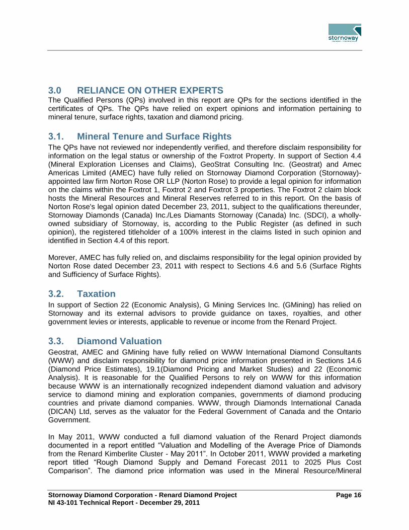
Stornoway Diamond Corporation - Renard Diamond Project Page 16 NI 43-101 Technical Report - December 29, 2011
3.0 RELIANCE ON OTHER EXPERTS The Qualified Persons (QPs) involved in this report are QPs for the sections identified in the certificates of QPs. The QPs have relied on expert opinions and information pertaining to mineral tenure, surface rights, taxation and diamond pricing.
Mineral Tenure and Surface Rights 3.1.The QPs have not reviewed nor independently verified, and therefore disclaim responsibility for information on the legal status or ownership of the Foxtrot Property. In support of Section 4.4 (Mineral Exploration Licenses and Claims), GeoStrat Consulting Inc. (Geostrat) and Amec Americas Limited (AMEC) have fully relied on Stornoway Diamond Corporation (Stornoway)-appointed law firm Norton Rose OR LLP (Norton Rose) to provide a legal opinion for information on the claims within the Foxtrot 1, Foxtrot 2 and Foxtrot 3 properties. The Foxtrot 2 claim block hosts the Mineral Resources and Mineral Reserves referred to in this report. On the basis of Norton Rose's legal opinion dated December 23, 2011, subject to the qualifications thereunder, Stornoway Diamonds (Canada) Inc./Les Diamants Stornoway (Canada) Inc. (SDCI), a wholly-owned subsidiary of Stornoway, is, according to the Public Register (as defined in such opinion), the registered titleholder of a 100% interest in the claims listed in such opinion and identified in Section 4.4 of this report. Morever, AMEC has fully relied on, and disclaims responsibility for the legal opinion provided by Norton Rose dated December 23, 2011 with respect to Sections 4.6 and 5.6 (Surface Rights and Sufficiency of Surface Rights).
Taxation 3.2.In support of Section 22 (Economic Analysis), G Mining Services Inc. (GMining) has relied on Stornoway and its external advisors to provide guidance on taxes, royalties, and other government levies or interests, applicable to revenue or income from the Renard Project.
Diamond Valuation 3.3.Geostrat, AMEC and GMining have fully relied on WWW International Diamond Consultants (WWW) and disclaim responsibility for diamond price information presented in Sections 14.6 (Diamond Price Estimates), 19.1(Diamond Pricing and Market Studies) and 22 (Economic Analysis). It is reasonable for the Qualified Persons to rely on WWW for this information because WWW is an internationally recognized independent diamond valuation and advisory service to diamond mining and exploration companies, governments of diamond producing countries and private diamond companies. WWW, through Diamonds International Canada (DICAN) Ltd, serves as the valuator for the Federal Government of Canada and the Ontario Government. In May 2011, WWW conducted a full diamond valuation of the Renard Project diamonds documented in a report entitled “Valuation and Modelling of the Average Price of Diamonds from the Renard Kimberlite Cluster - May 2011”. In October 2011, WWW provided a marketing report titled “Rough Diamond Supply and Demand Forecast 2011 to 2025 Plus Cost Comparison”. The diamond price information was used in the Mineral Resource/Mineral

Stornoway Diamond Corporation - Renard Diamond Project Page 17 NI 43-101 Technical Report - December 29, 2011
Reserve estimates and the financial analysis, and their diamond supply and demand forecasts were referenced in the Market Studies section. The diamond price information could not be verified by the QPs due to the proprietary nature of the diamond price book used for the valuation. Risk exists that the diamond price values obtained from WWW may differ from those achieved during commercial production since the valuation was based on an exploration sized sample.

Stornoway Diamond Corporation - Renard Diamond Project Page 18 NI 43-101 Technical Report - December 29, 2011
4.0 PROPERTY DESCRIPTION AND LOCATION
Location 4.1.The Foxtrot Property is situated in the Monts Otish (Otish Mountains) region of the province of Québec, Canada, 820 km north of the city of Montréal and 360 km north-northeast of the mining town of Chibougamau (Figure 4.1). The property lies 120 km south of the all-weather Trans-Taïga highway and 150 km south-southeast of Hydro-Québec’s LG-4 electricity generating station. The closest settlement is Témiscamie, on Lac Albanel approximately 210 km to the south, which is connected by all-weather provincial road #167 to the Cree Community of Mistissini. Much of the property is encompassed within National Topographic Sheet (NTS) 033A16, although there are also smaller portions in NTS 033A09 and 033H01 (Figure 4.2). Project centroids are at approximately 52°49’N and 72°12’W. There are currently no active mining operations in the immediate vicinity of the Foxtrot Property, but there are numerous active exploration projects primarily to the south and west.
Tenure History 4.2.Stornoway Diamond Corporation (Storonway) was created in 2003 as a result of a plan of arrangement between Northern Empire Minerals Ltd. and Stornoway Ventures Ltd. Exploration leading to the acquisition of the Foxtrot Property commenced in 1996 under a 50:50 joint venture agreement dated March 14, 1996 (and subsequent amendments) between Ashton Mining of Canada Inc. (Ashton) and SOQUEM Inc. (SOQUEM), with Ashton as operator. The purpose of the initial agreement was to explore for diamonds within an area of mutual interest (AMI) in the Ungava Region of Québec. Subsequently, the joint venture partnership was reassigned to Ashton Diamonds (Canada) Inc. and DIAQUEM Inc. (DIAQUEM), a wholly-owned subsidiary of SOQUEM. Stornoway acquired Ashton and Ashton’s 50% property interest in January 2007. On December 14, 2010, Stornoway reported that it had entered into an agreement with DIAQUEM for the acquisition of DIAQUEM's 50% interest in the Renard Project. This acquisition was completed on April 01, 2011. Stornoway Diamonds (Canada) Inc., a wholly-owned subsidiary of Stornoway, now owns 100% of the Renard Project, subject to a 2% direct royalty interest on future diamond production in favour of DIAQUEM. When initially granted through online staking activities in 2000 and 2001, the Property consisted of two Mining Exploration Licences, PEM 1555 and PEM 1556, and 2,121 claims. Since that time, claims were allowed to lapse in 2007 (500 claims), 2009 (1,161 claims) and 2011 (157 claims). In June of 2010, in preparation for the expiration of the Mining Exploration Licenses at the end of each of their respective final terms on August 28, 2010, 744 mineral claims were staked via map designation over PEM 1555 and the northern portion of PEM 1556.

Stornoway Diamond Corporation - Renard Diamond Project Page 19 NI 43-101 Technical Report - December 29, 2011
Figure 4.1: Location Map
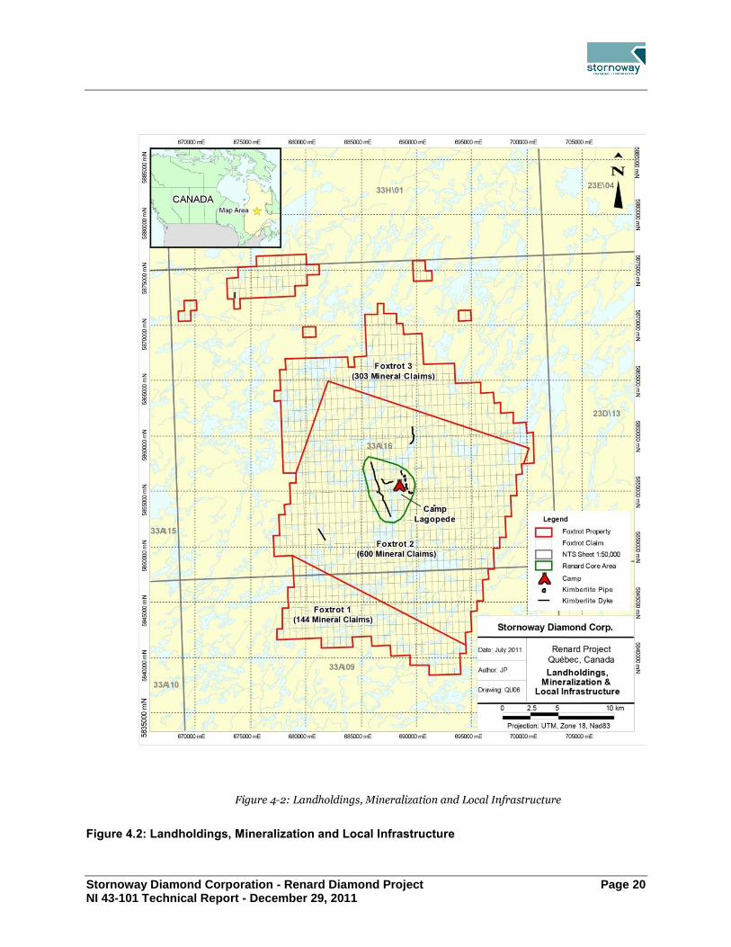
Stornoway Diamond Corporation - Renard Diamond Project Page 20 NI 43-101 Technical Report - December 29, 2011
Figure 4.2: Landholdings, Mineralization and Local Infrastructure

Stornoway Diamond Corporation - Renard Diamond Project Page 21 NI 43-101 Technical Report - December 29, 2011
During the map designation process 51 already existing partial cells from the Foxtrot 3 block which bordered PEM 1555 were extended to full sized cells. The current landholdings (Figure 4.2) are registered in the name of SDCI as to a 100% interest. The Renard kimberlite pipes and the Lynx and Hibou dykes, are all located well within the boundaries of the contiguous block of 744 mineral claims that comprise the Foxtrot 1 and Foxtrot 2 claim blocks.
Mineral Tenure in Québec 4.3.Mining Exploration Licences are issued in Québec for a period of five years and may be renewed for one additional five-year period provided the conditions of renewal described in the Mining Act (Québec)(R.S.Q., c. M-13.1) (Mining Act) are met. Prior to expiry of the Mining Exploration Licence (PEM), the entire area may be converted to mining claims in an online process, and the excess exploration expenditures (or credits) carried over from the PEM to the new claims. In Québec, claims are issued based on a two-year assessment period with the work requirements increasing for each period. Renewal fees paid earlier than 60 days prior to the anniversary date are fixed by regulation and are currently set at $123.00 per claim. If a renewal application is submitted after that date but prior to the claim’s date of expiry, the current prescribed fee of $123.00 per claim is doubled. The claim holder has the exclusive right to search for all mineral substances in the public domain, with the exception of petroleum, natural gas, brine and loose surface materials. In accordance with the Mining Act a claim holder must comply with the obligation to carry out work on the claims in an amount based on the surface area of the claim and its location in relation to the 52nd parallel. When the work carried out is insufficient, or if work was not carried out, the titleholder may pay an amount equivalent to the required amount in lieu of work. Alternately, excess exploration credits from other claims within a 4.5 km radius may be transferred to meet any shortfall.
Mineral Exploration Licences and Claims 4.4.The Foxtrot Property comprises three groups of separate but essentially contiguous landholdings known as the Foxtrot 1, Foxtrot 2 and Foxtrot 3 blocks, covering a total area of 54,550.18 (Figure 4.2). Foxtrot 1 and Foxtrot 2 consist of 744 individual claims (38,796.72ha), and Foxtrot 3 contains 303 individual claims (15,753.46ha). Fifty-eight claims in five groups belonging to Foxtrot 3, and included in the totals above, lie north of the main block and are non-contiguous (Figure 4.2). The claims are registered in the names of SDCI as a 100% interest. At the effective date of this report, all claims are reported by Stornoway to be in good standing. All but one of the 744 new claims staked within PEM 1555 and PEM 1556 currently have anniversary dates of either August 15, 2012 or August 16, 2012 and can be identified by the following claim numbers in the public register of real and immovable mining rights kept at the

Stornoway Diamond Corporation - Renard Diamond Project Page 22 NI 43-101 Technical Report - December 29, 2011
Ministère des Ressources naturelles et de la Faune (MRNF): CDC2245719 to CDC2245968 (inclusive), CDC2245973 to CDC2246148 (inclusive), CDC2246150, CDC2246152, CDC2246154, CDC2246156, CDC2246158, CDC2246160, CDC2246162, CDC2246164, CDC2246166, CDC2246168, CDC2246170, CDC2246201 to CDC2246252 (inclusive), CDC2246295 to CDC2246314 (inclusive), CDC2246321 to CDC2246473 (inclusive), CDC 2246493 to CDC2246573, and CDC2251694. The latter claim holds an anniversary date of September 27, 2012. All known kimberlite mineralization, including the pipes and the dyke systems, as well as the existing infrastructure, including Camp Lagopède, diesel generators, underground infrastructure, the on-site dense media separation (DMS) facility, and processed kimberlite containment facility, that is associated with the Foxtrot Property, are situated within the boundaries of the Foxtrot 2 claim block. A single, narrow (approximately 0.1 m thickness), north-trending kimberlite dyke with an estimated strike length of 450 m straddles mining claims 1009366 and 1009385. No other kimberlites are known within the Foxtrot 3 claims.
Agreements 4.5.Stornoway holds a 100% interest in the Property, subject to a 2% direct royalty on future diamond production in favour of DIAQUEM, effective April 01, 2011 and as documented in an Acquisition and Exchange Agreement between DIAQUEM and Stornoway dated December 14, 2010 and Amended on February 08, 2011.
Surface Rights 4.6.The Foxtrot Property, including the Renard kimberlite pipes and the Lynx and Hibou kimberlite dykes, is situated within the region of northern Québec governed by the James Bay and Northern Québec Agreement 1975, as amended (JBNQA), a land claims agreement executed by the Government of Québec, the Government of Canada, the Grand Council of the Cree of Québec (GCC) and the Northern Québec Inuit Association, amongst others. The JBNQA provides for three categories of land, Categories I to III, each with specifically defined rights. The Foxtrot Property lies within Category III lands in an area in proximity to the community of Mistissini (the Cree Nation of Mistissini, or CNM). Category III lands are public lands where Cree communities have certain rights, particularly in regard to trapping, hunting, fishing and the development of outfitter operations. Surface and mineral rights on Category III lands reside with the Government of Québec and are governed by the applicable land use laws and regulations, implemented by the relevant regulatory authorities. Members of the CNM undertake hunting, fishing and trapping activities within the Foxtrot Property, with the Renard kimberlites occurring in an area known to them as “yuus-kanchiisu-saakahiikan” (mild rock ptarmigan lake). More specifically, the Renard kimberlites lie within the CNM trapline area designated as M-11, used by Sydney and Roderick Swallow (known as the ‘tallyman’). Under the terms of the JBNQA, governments have the right to develop Category III lands. However, mining projects among others are subject to an environmental and social protection regime, which provides for the protection of the hunting, fishing and trapping rights of the Cree.

Stornoway Diamond Corporation - Renard Diamond Project Page 23 NI 43-101 Technical Report - December 29, 2011
SDCI, as holder of a claim, has the exclusive right to explore for mineral substances on the parcel of land subject to the claim, with the exception of: (i) petroleum, natural gas and brine; (ii) sand other than silica sand used for industrial purposes, gravel, common clay used in the manufacture of clay products and every other mineral substance found in its natural state as a loose deposit, as well as inert mine tailings used for construction purposes; and (iii) on any part of the parcel of land that is also subject to an exploration license for surface mineral substances or an exclusive lease to mine surface mineral substances, every other surface mineral substance. Moreover, the claim provides access rights to the parcel of land subject to the claims on which exploration work may be performed. A claim holder cannot access land that has been granted, alienated or leased by the State for non-mining purposes, or land that is the subject of an exclusive lease to mine surface mineral substances, without first having obtained the permission of the holder of these rights. SDCI is required to carry out assessment work prior to the 60th day preceding the expiry date of a claim. The nature and value of the work are determined by regulation. The amount of the assessment work to be carried out during each term of a claim varies according to the number of terms since its issuance, the surface and the locations. To mine mineral substances (except surface mineral substances, petroleum, natural gas and brine) in the Province of Québec, SDCI will be required to obtain a mining lease in accordance with the Mining Act. To obtain a mining lease in respect of all or a part of a parcel of land that is subject to one or several claims, SDCI will be required to establish the indicators of the presence of a workable deposit, provided it also meets prescribed requirements and pays the applicable annual rent. SDCI will, provided it is granted a mining lease in accordance with the Mining Act have as lessee the rights and obligations of an owner on the land that is subject to such mining lease, including surface and usage rights. On lands in the public domain, access and the right to use the surface of the land are limited to mining purposes only.
Permits 4.7.4.7.1 Exploration
Currently, work on the Project is conducted in accordance with the terms and conditions contained within the surface exploration permit and other permits that are required for the camp, fuel storage and exploration activities. Stornoway has received the permits and approvals it needed to operate and conduct the associated advanced exploration activities completed to date.
4.7.2 Future Work
The Renard Project must obtain global environmental approvals under various legislation, including the Mining Act, the Environment Quality Act (R.S.Q. c. Q-2) (EQA), the Canadian Environmental Assessment Act (S.C., c. 37) (CEAA) and the JBNQA. Table 4.1 lists the

Stornoway Diamond Corporation - Renard Diamond Project Page 24 NI 43-101 Technical Report - December 29, 2011
potentially necessary authorizations, permits, approvals, attestations and leases for the Renard Project. The JBNQA was implemented in 1975 by the Québec government, the Government of Canada, the Grand Council of the Crees (Eeyou Istchee) (GCC-EI) and the Association des Inuits du Nouveau-Québec. The JBNQA defines the social and environmental protection regimes for the regions of James Bay and Nunavik. The Renard Project is subject to the provincial process for the assessment and review of social and environmental impacts under the JBNQA. Three land categories were established in the JBNQA: category I, II and III. Specific rights are defined for each one. The Foxtrot Property is located on category III land of the community of the CNM. Chapter II of the EQA provides specific provisions for environmental assessments applicable to the James Bay territory, in accordance with the provisions of the JBNQA. The environmental assessment procedure specific to this region differs from the provincial procedure, as it involves the active participation of the Aboriginal people who live there. The Ministère du Développement durable, de l’Environnement et des Parcs (MDDEP) is responsible for coordinating the review of the impact assessment study as a representative of the Québec government. However, other departments, such as the MRNF and the Ministère des Transports (MTQ) may also be involved in the review as experts. The Québec government is responsible for mining activities in the province. This activity is subject to the Mining Act which defines ownership of the right to mineral substances (claims, mining exploration licenses, mining leases, mining concessions, etc.) and the rights and obligations of the claim holder or other mining right granted by the State. The CEAA is applicable to projects for which the federal government has decision-making powers under Section 5 of the CEAA, as a proponent, administrator of federal lands, funding source or regulatory body. For the Renard Project, the Fisheries and Oceans Canada (DFO) must grant authorization to modify the fish habitat under Subsection 35(2) of the Fisheries Act R.S.C. 1985, C. F-14). The Canadian Environmental Assessment Agency is considered the responsible authority for the Renard Project and DFO and TC are considered experts. Under federal regulations, the Renard Project is subject to a comprehensive federal environmental assessment, in accordance with section 21 of the CEAA. At the end of the impact assessment, after receiving global environmental approval from the MDDEP and from the federal government under the CEAA, the proponent may begin preparing the final plans and specifications. In addition to the mitigation measures set out in the environmental and social impact assessment, the final Project design must comply with the applicable standards for projected infrastructures and equipment. The preparation of plans and specifications must follow the legal framework of the governments of Québec and Canada. Following the submission of the Project Notice in February 2010, the MDDEP and Comité d'évaluation (COMEV) issued guidelines to Stornoway on the scope of the impact assessment to be carried out for the Renard Diamond Mine Project (June 2010). A modification to the Project Notice was submitted to the MDDEP, COMEV and the Canadian Environmental Assessment Agency in February 2011, informing them of some changes made to the Project since February 2010. The Environmental and Social Impact Assessment (ESIA) was conducted

Stornoway Diamond Corporation - Renard Diamond Project Page 25 NI 43-101 Technical Report - December 29, 2011
in 2010-2011 by Roche ltée Group-Conseil. The ESIA report was submitted to the Administrator on December 23, 2011.
Socio-Economics 4.8.The Foxtrot Property is located within the region of Northern Québec governed by the JBNQA, as amended, a land claims agreement executed by the Government of Québec, the Government of Canada, the GCC and the Northern Québec Inuit Association, among others. In February 2002, Québec and the Cree Nation signed a fifty year political and economic agreement. This agreement is the La Paix des Braves. The GCC is the political body that represents approximately 14,500 Crees of Eastern James Bay and Southern Hudson Bay in Northern Québec. The GCC has twenty members: a Grand Chief and Deputy-Grand Chief elected at large, the chiefs elected by each of the nine Cree communities of the territory, and one other representative from each community. The closest community to the Renard Project is Mistissini, located southeast of the largest natural lake in Québec, Lac Mistassini, approximately 90 km northeast of Chibougamau. The site on which the community is built was once used as a basic summer encampment where the Hudson Bay Company settled in the early 1800s. In terms of population (3,500 residents), Mistissini is one of the largest Cree communities in Québec. Its economic activities are mainly concentrated in the business and service sectors (health and education), forestry, trapping, tourism, outfitting, construction and transportation. The limits of the Jamesian Territory essentially follow the boundaries of the Municipality of James Bay (MBJ), a vast regional administrative entity that includes the towns of Chibougamau, Chapais, Lebel sur-Quévillon and Matagami. The MBJ communities most affected by the Renard Project are Chibougamau and Chapais. Mining exploration has played a leading role in the economic development of Chibougamau and Chapais. The completion of a cart road linking Saint-Félicien to Lac-Saint-Jean and Chibougamau led to the establishment of the village of Chibougamau, which received its status as a municipal corporation on September 1, 1954. After the Campbell mine became operational in 1955, Chibougamau saw rapid expansion with the development of rich polymetallic deposits (gold, copper and silver) and the population grew year over year until the late 1970s, when it reached its highest levels. The economy of Chibougamau and Chapais became progressively diversified with forestry and the development of the public and private service sector.
Risks 4.9.The ongoing ESIA process for the Renard Project is based on the most current and detailed information available on the physical, biological and human environment. The information was provided by the Feasibility Study team through best environmental assessment practices that are recognized by government institutions. These inputs, in combination with information from the local communities and consultation meetings held with local stakeholders, form the basis of the environmental assessment process.

Stornoway Diamond Corporation - Renard Diamond Project Page 26 NI 43-101 Technical Report - December 29, 2011
The environmental assessment process includes environmental design measures which prevent and minimise environmental and social impacts and risks, and limit the extent and consequences of these potential risks and impacts. The environmental assessment process also allows for the development of specific mitigation and compensation measures that are consistent with government guidelines to minimize or compensate these impacts or risks to acceptable levels. Any residual impacts will be managed through an environmental management plan that includes environmental monitoring and surveillance. Environmental and social residual risks to the Project schedule or implementation were identified and addressed as part of the Feasibility Study in a risk register. They are discussed in Section 24.4 of the present report.

Stornoway Diamond Corporation - Renard Diamond Project Page 27 NI 43-101 Technical Report - December 29, 2011
Table 4.1: List of Potentially Necessary Authorizations, Permits, Approvals, Attestations and Leases
Description Department Regulations/Act/Code
Provincial government
Authorizations
Certificate of authorization to carry out mining project Construction of airstrip Installation of water intake in Lakes Poisson and Lake Lagopède Construction of dyke in Lake Lagopède and drainage of bay Dredged sediment storage Water diversion Construction and operation of power station Mining operations (pits, dumps and tailings sites) Operation of ore processing plant EDO - treated industrial water (mining operations) Explosives magazine and service building Installation and operation of oil separator - Garage - Power station Trench landfill Hazardous material management and storage Incineration of waste oil as fuel Incinerator - Waste management Lagopède mobile concrete plant Sand and gravel operation (borrow pits)
MDDEP Section 22 of the Environment Quality Act (R.S.Q., c. Q-2)
Authorization to conduct an activity likely to alter a wildlife habitat Activities affecting fish habitat (water diversion, water removal and withdrawals, etc.) Does not apply to docks, trails, roads, culverts or bridges built in accordance with the conditions set out in Division VI of the Regulation respecting wildlife habitats
MRNF - Wildlife Section 128.7 of the Act respecting the conservation and development of wildlife (R.S.Q., c. C-61.1) Division VI of the Regulation respecting wildlife habitats
Bulk sampling authorization Bulk sampling of more than 50 metric tonnes
MRNF - Mines Section 59 of the Mining Act (R.S.Q., c. M-13.1)
Authorization to install apparatus or equipment to prevent, reduce or cause the cessation of the issuance of contaminants into the atmosphere
MDDEP Section 48 of the Environment Quality Act (R.S.Q., c. Q-2)
Authorization to establish water intakes, water purification appliances, and devices for the treatment of wastewater Camp - permanent (wastewater) Camp - permanent (potable water) EDO - treated sanitary wastewater (permanent camp)
MDDEP Section 32 of the Environment Quality Act (R.S.Q., c. Q-2)
Authorization to build high-capacity dam Lake Lagopède dam
Centre d'expertise hydrique du Québec -
MDDEP
Section 5 of the Dam Safety Act (R.S.Q., c. S-3.1.01) Division VI of the Dam Safety Regulation (c. S-3.1.01, r. 1)
Approval
Approval for the localization of mine tailings concentration and disposal plant
MRNF - Mines Sections 240 and 241 of the Mining Act (R.S.Q., c. M-13.1) Sections 124 and 125 of the Regulation

Stornoway Diamond Corporation - Renard Diamond Project Page 28 NI 43-101 Technical Report - December 29, 2011
respecting mineral substances other than petroleum, natural gas and brine (c. M-13.1, r. 2)
Attestation
Depollution attestation (Industrial waste reduction program)
MDDEP Section 31.10 of the Environment Quality Act (R.S.Q., c. Q-2) Order in Council 515-2002 of May 1, 2002, respecting the application of subdivision 1 of Division IV.2 of Chapter I of the Environment Quality Act to the mineral industry and primary metal manufacturing sector
Permits
Forest management permit for mining activities All deforestation activities
MRNF - Forests Chapter I, Divisions I and II of the Forest Act
(R.S.Q., c. F-4.1) Regulation respecting standards of forest management for forests in the domain of the State (c. F-4.1, r. 7)
Occupation licence for work involving the collection or discharge of water Water intake in Lake Poisson Water intake in Lake Lagopède
Centre d'expertise hydrique du Québec -
MDDEP
Section 10 of the Regulation respecting the water property in the domain of the State (c. R-
13, r. 1.1)
Explosives permit (general, magazine and transport) Sûreté du Québec An Act respecting explosives (R.S.Q., c. E-22,
a. 22) Division II of Regulation under the Act respecting explosives (c. E-22, r. 1)
High-risk petroleum equipment operation permit Mine site Airstrip
Régie du bâtiment du Québec
Section 120 of the Safety Code (c. B-1.1, r.
0.01.01.1) Section 8.12 of the Construction Code (c. B-1.1, r. 0.01.01)
Leases
Mining leases MRNF - Mines Section 100, Division V of the Mining Act
(R.S.Q., c. M-13.1)
Non-exclusive lease to mine surface mineral substances Borrow pits, quarries and sand pits
MRNF - Mines Section 140, Division VII of the Mining Act (R.S.Q., c. M-13.1)
Lease for the occupation of the State’s hydric domain Lake Lagopède dyke
Centre d'expertise hydrique du Québec -
MDDEP
Section 19 of the Regulation respecting the water property in the domain of the State (c. R-
13, r. 1.1)
Lease to occupy the domain of the State Dumps and tailings sites Camp Airstrip Explosives magazine Trench landfill
MRNF - Territory Section 239 of the Mining Act (R.S.Q., c. M-13.1) Section 47, Division II of the Act respecting the lands in the domain of the State (R.S.Q., c. T-8.1) Section 35 of the Regulation respecting the sale, lease and granting of immovable rights on lands in the domain of the State (c. T-8.1, r. 7)
Notice to Minister
Notice to Minister to establish an industrial camp MDDEP Section 2 of the Regulation respecting sanitary conditions in industrial or other camps (c. Q-2,
r. 11)
Federal government
Authorization

Stornoway Diamond Corporation - Renard Diamond Project Page 29 NI 43-101 Technical Report - December 29, 2011
Authorization to modify fish habitat All activities affecting fish habitat
Fisheries and Oceans Canada
Section 35 of the Fisheries Act (R.S.C., 1985, c. F-14)
Approval
Approval of works in, over, under, through, or across any navigable waterway Lake Lagopède dyke
Transport Canada Section 5 of the Navigable Waters Protection Act (R.S.C., 1985, c. N-22)
Licence
Licence for the manufacturing of explosives Natural Resources Canada
Paragraph 7(1)(a) of the Explosives Act (R.S.C., 1985, c. E-17) Section 25 of the Explosives Regulations (C.R.C., c. 599)
Registration
Registration of an aerodrome1 Transport Canada Section 301.03 of the Canadian Aviation
Regulations, Part III, Subpart 1 - Aerodromes
Municipality of James Bay (municipality outside RCM)
Certificates
Certificate of compliance with municipal bylaws - Service infrastructure
– An Act to amend the James Bay Region Development Act and other legislative provisions (Bill n°40) Certificate of compliance with municipal bylaws - Road –
Certificate of compliance with municipal bylaws - Camp –
Certificate of compliance with municipal bylaws - Airstrip infrastructure
–
Permits
Permit for individual work on groundwater catchment (Airstrip)
– An Act to amend the James Bay Region Development Act and other legislative provisions (Bill n°40) Permit for septic system installation (Airstrip)
1Aerodrome: Any area of land, water (including the frozen surface thereof) or other supporting surface used, designed, prepared,
equipped or set apart for use either in whole or in part for the arrival, departure, movement or servicing of aircraft and includes any buildings, installations and equipment situated thereon or associated therewith.

Stornoway Diamond Corporation - Renard Diamond Project Page 30 NI 43-101 Technical Report - December 29, 2011
5.0 ACCESSIBILITY, CLIMATE, LOCAL RESOURCES, INFRASTRUCTURE AND PHYSIOGRAPHY
Accessibility 5.1.5.1.1 Air
During summer months, float-equipped, fixed-wing aircraft and, during the winter months, ski-equipped aircraft can be leased from various hunting and fishing outfitters in the area or from small air service companies in Chibougamau, Mistissini, Témiscamie or Wemindji. Rotary wing aircraft can also be chartered. The Chibougamau–Chapais airport has daily scheduled flights to Montréal. Flight time from Chibougamau to the Property varies from one to two hours depending on the type of aircraft used. An ice airstrip measuring up to 1,250 m in length has previously been constructed near Camp Lagopède to allow operation of large aircraft for mobilization of equipment and supplies. In the summer, fixed-wing access directly to the Property requires the use of float planes, which can land at a dock at Camp Lagopède. During fall freeze-up and spring break-up, access to the Property necessitates the use of helicopters. The nearest permanent helicopter base is located in Chibougamau. Chartered helicopters are frequently staged on the Property.
5.1.2 Road
Highway 109, an all-weather paved road, originates in Matagami, Québec, and terminates approximately 500 km north at the LG-2 hydroelectric generating station in Radisson. Two major, all-weather, gravel roads lead east from this highway into the interior of Québec (Figure 4.1). The North Road connects Chibougamau with the James Bay Highway via Nemiscau. The Trans-Taïga Highway runs east from Radisson (LG-2) to Caniapiscau and provides gravel road access to the LG-3, LG-4, Laforge 1, Laforge 2 and Centrale Brisay hydro sites as well as to several caribou hunting lodges. LG-4 is approximately 150 km from the Renard site. Pourvoirie Mirage (Mirage), a hunting/fishing lodge located approximately 50 km to the east of LG-4 along the Trans-Taïga Highway, owns and operates an all-weather airstrip. Mirage is approximately 120 km from the Project, and provides a staging point for the transfer of trucked material to either fixed-wing or rotary-wing aircraft. Provincial road 167 affords paved access to the city of Chibougamau and the village of Misstissini, and links these communities to the provincial road network. A 150 km, all-weather gravel road proceeds north from the village of Mistissini to Témiscamie. A winter road leads north from Temiscamie for another 175 km to the historic Eastmain gold mine. At its closest point, the winter road is approximately 58 km south of the Foxtrot Property. In recent winters, fuel and supplies have been transported on this road to a point approximately 40 km south of the road’s northern terminus. This northernmost, 40 km section of the road is currently closed, and has not been assessed for operability. Between 2004 and 2008, a system of unpaved local roads and trails was constructed between Camp Lagopède, the Renard Core Area, the Hibou and the Lynx dyke areas and various exploration drill sites. There is no road linking the Property to any outside roads.

Stornoway Diamond Corporation - Renard Diamond Project Page 31 NI 43-101 Technical Report - December 29, 2011
On August 1, 2011 Stornoway Diamond Corpoation (Stornoway) executed two separate agreements with the Ministère des Ressources naturelles et de la Faune and the Ministère des Transports (MTQ) to provide financial assistance for the Route 167 extension. Stornoway has agreed to contribute $44 million to the development of the new road over a ten year period starting in July 2015. Stornoway’s contribution will be financed by Québec at 6.3% and will be conditional upon, amongst other things, the completion of the road on schedule, the receipt of all regulatory approvals for the construction of the Renard Project and the successful completion of Renard Project financing. In addition, Stornoway has agreed to contribute a maximum of $5,000 per kilometre, or $1.215 million per year, to the maintenance of the road during operation. Québec will seek similar cost recovery from other industrial users. Stornoway expects road construction to commence in early 2012, and anticipates first vehicle access to the Renard site for construction mobilization by the second quarter of 2013 through the utilization of an upgraded seasonal road and construction easements. A winter road from the north could be considered by Stornoway if the southern route option is delayed.
Climate / Operating Seasons 5.2.Climate at the Renard site is characterized by long winters and short summers. Temperatures range from summer maximums of +35°C to winter minimums of -45°C. Lakes freeze over in late October, thawing in late April–May. Abundant precipitation falls in the form of rain and snow. Total annual precipitation averages around 80 - 100 cm. The Otish Mountains form a local topographic high that affects both precipitation and fog formation and distribution in the area. Fog and low-lying clouds can cause delays to aircraft operating in the area. Forest fires are common in the area during the spring and summer months, but to date have not adversely affected the Project.
Local Resources and Infrastructure 5.3.5.3.1 Local Resources
The nearest communities to the Foxtrot Property are Chibougamau (population about 8,000), Mistissini (pop 3,500), and Wemindji (pop 1,300). Chibougamau serves as the major supply centre for regional industries. Two field camps were constructed on the Foxtrot Property: Emmanuel and Lagopède. During the winter, a 15 km snowmobile trail connected the two camps. Camp Emmanuel originally had the capacity to lodge up to 35 persons, but is currently decommissioned. Camp Lagopède, which can host 75 persons, is used to stage all project related activities. The site has a satellite communications system, a secure logging facility, a fenced storage area for holding kimberlitic samples, a garage equipped with a welding shop, and a 10 tph Dense Media Separation (DMS) facility.

Stornoway Diamond Corporation - Renard Diamond Project Page 32 NI 43-101 Technical Report - December 29, 2011
5.3.2 Power
Power is supplied to the site by diesel generators. Currently, all fuel is flown to the site. The hydroelectric generating station at LG-4, located approximately 150 km to the north–northwest of the Foxtrot Property (Figure 4.1), could potentially supply power to the Property. Stornoway is financing an independent feasibility study and environmental assessment for a power line. The power line studies are being conducted by Hydro-Québec separately from the feasibility study.
5.3.3 Transport
The airport facilities at LG-4 and Chibougamau, and the fixed-wing float bases in Mistissini, Témiscamie and Mirage are used as staging areas for mobilization of equipment and personnel to the Project site.
5.3.4 Water
In the past, water was required to support camp operations and the process plant. Depending on the immediate requirements and the relevant usage permits, process water was sourced from local lakes or recirculated from surface facilities such as the processed kimberlite containment area or the underground exploration workings. During the 2007 underground bulk sampling program, three different types of water were managed on the Foxtrot Property:
Used water from the Lagopède camp operation: A water treatment system was set up in 2006 and approved by the Ministère du Développement durable, de l'Environnement et des Parcs (MDDEP). It consists of four series of Enviro–Septic system units connected to a cleaning field established behind the campsite.
Used water from the underground exploration program: A water treatment system approved by the MDDEP was set up underground, together with an outside water-settling pond that was monitored by Stornoway and reported monthly to the appropriate government agency. This pond was decommissioned in August 2008 following MDDEP regulations.
Used water for the DMS operation: This water was completely recirculated from the DMS facility into the adjacent settling pond as approved by the MDDEP. DMS process water did not require any specific water treatment.
The potable water system used for the Lagopède camp operation is a portable ozone water treatment system, Expio, which is manufactured by Aquagenex in Clermont, Québec. There are two units available on site. The system can produce up to 100 gallons (378 L) per day, a sufficient quantity for the operations to date.
Physiography 5.4.Topographic relief within the Foxtrot Property consists of steep-sided hills with rounded tops separated by muskeg-covered valleys. Elevations range between 400 masl and 800 masl. Lakes, ponds and small rivers are common.

Stornoway Diamond Corporation - Renard Diamond Project Page 33 NI 43-101 Technical Report - December 29, 2011
Flora and Fauna 5.5.The Foxtrot Property is located in the Taïga belt of Northern Québec. Vegetation consists largely of immature to mature black spruce, poplar, alders and muskeg, with increasing proportions of muskeg and black spruce toward the north. Animals such as bear, fox, moose, marten and caribou, as well as various species of birds, are present in the vicinity of the Foxtrot Property.
Sufficiency of Surface Rights for Mining Operations 5.6.The sufficiency of surface rights for mining operations is discussed in Sections 4.5 and 4.6.
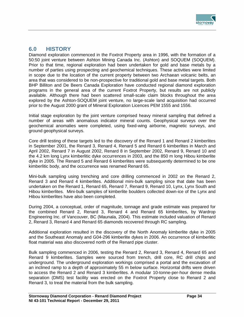
Stornoway Diamond Corporation - Renard Diamond Project Page 34 NI 43-101 Technical Report - December 29, 2011
6.0 HISTORY Diamond exploration commenced in the Foxtrot Property area in 1996, with the formation of a 50:50 joint venture between Ashton Mining Canada Inc. (Ashton) and SOQUEM (SOQUEM). Prior to that time, regional exploration had been undertaken for gold and base metals by a number of parties using prospecting and geochemical techniques. These activities were limited in scope due to the location of the current property between two Archaean volcanic belts, an area that was considered to be non-prospective for traditional gold and base metal targets. Both BHP Billiton and De Beers Canada Exploration have conducted regional diamond exploration programs in the general area of the current Foxtrot Property, but results are not publicly available. Although there had been scattered small-scale claim blocks throughout the area explored by the Ashton-SOQUEM joint venture, no large-scale land acquisition had occurred prior to the August 2000 grant of Mineral Exploration Licences PEM 1555 and 1556. Initial stage exploration by the joint venture comprised heavy mineral sampling that defined a number of areas with anomalous indicator mineral counts. Geophysical surveys over the geochemical anomalies were completed, using fixed-wing airborne, magnetic surveys, and ground geophysical surveys. Core drill testing of these targets led to the discovery of the Renard 1 and Renard 2 kimberlites in September 2001, the Renard 3, Renard 4, Renard 5 and Renard 6 kimberlites in March and April 2002, Renard 7 in August 2002, Renard 8 in September 2002, Renard 9, Renard 10 and the 4.2 km long Lynx kimberlitic dyke occurrences in 2003, and the 850 m long Hibou kimberlite dyke in 2005. The Renard 5 and Renard 6 kimberlites were subsequently determined to be one kimberlitic body, and the occurrence was renamed Renard 65. Mini-bulk sampling using trenching and core drilling commenced in 2002 on the Renard 2, Renard 3 and Renard 4 kimberlites. Additional mini-bulk sampling since that date has been undertaken on the Renard 1, Renard 65, Renard 7, Renard 9, Renard 10, Lynx, Lynx South and Hibou kimberlites. Mini-bulk samples of kimberlite boulders collected down-ice of the Lynx and Hibou kimberlites have also been completed. During 2004, a conceptual, order of magnitude, tonnage and grade estimate was prepared for the combined Renard 2, Renard 3, Renard 4 and Renard 65 kimberlites, by Wardrop Engineering Inc. of Vancouver, BC (Maunala, 2004). This estimate included valuation of Renard 2, Renard 3, Renard 4 and Renard 65 diamonds recovered through RC sampling. Additional exploration resulted in the discovery of the North Anomaly kimberlite dyke in 2005 and the Southeast Anomaly and G04-296 kimberlite dykes in 2006. An occurrence of kimberlitic float material was also discovered north of the Renard pipe cluster. Bulk sampling commenced in 2006, testing the Renard 2, Renard 3, Renard 4, Renard 65 and Renard 9 kimberlites. Samples were sourced from trench, drill core, RC drill chips and underground. The underground exploration workings comprised a portal and the excavation of an inclined ramp to a depth of approximately 55 m below surface. Horizontal drifts were driven to access the Renard 2 and Renard 3 kimberlites. A modular 10-tonne-per-hour dense media separation (DMS) test facility was erected on the Foxtrot Property close to Renard 2 and Renard 3, to treat the material from the bulk sampling.

Stornoway Diamond Corporation - Renard Diamond Project Page 35 NI 43-101 Technical Report - December 29, 2011
In December 2008, an economic assessment study jointly undertaken by Agnico-Eagle Mines Limited (Agnico-Eagle) and AMEC Americas Limited (AMEC), was completed and formed the 2008 NI 43-101 Technical Report on the Preliminary Assessment of the Renard Project authored by Scott Wilson Roscoe Postle Associates Inc. (SWRPA). Agnico-Eagle was responsible for mining, cost estimating and financial analysis. Elements of the Agnico-Eagle mining study, such as cost estimation, were completed to a pre-feasibility standard. AMEC designed the DMS facility, and prepared the Mineral Resource Estimate. Given the more conceptual nature of the mine plan, and inclusion of Inferred Resources from AMEC’s Mineral Resource Estimate used in the study, the two studies combined comprise a Preliminary Assessment under the definitions contained within NI 43-101. An audit of the Agnico-Eagle study and economic analysis was completed by SWRPA, as independent Qualified Persons for the 2008 NI 43-101 report. The December 12, 2008 Technical Report was revised on March 25, 2009 to clarify that the QPs were taking responsibility for the WWW International Diamond Consultants valuation and that diamond valuations are not amenable to data verification procedures that can be performed by a QP. None of the scientific and technical information in the report changed. Golder Associates Ltd. (Golder) completed a 2009 updated resource estimate which formed the NI 43-101 2009 Mineral Resource Update for the Renard Project (Farrow, 2010). The effective date of the report was December 8, 2009. The initial report was dated January 21, 2010, and revised on January 27, 2010. The revision did not make any material changes to the initial report. SWRPA was then retained by Stornoway Diamond Coroporation (Stornoway) to prepare an update of the March 25, 2009 Independent Technical Report on the Project. The purpose of the report was to provide an updated document for the disclosure of a Preliminary Assessment of a potential mining and processing operation at the Project. A Preliminary Assessment of the Project was completed on March 22, 2010. This study comprised a conceptual mine plan, capital and operating cost estimates, and cash flow model prepared by SWRPA; a diamond processing plant design, with capital and operating cost estimates, prepared by AMEC; and social, environmental and permitting aspects contributed by Stantec. The conceptual mine plan was based upon the National Instrument (NI) 43-101 compliant mineral resource estimate prepared by Golder. Golder, AMEC and Stantec prepared or contributed to sections of the Technical Report. This May 5, 2010 Technical Report conformed to NI 43-101 Standards of Disclosure for Mineral Projects (Lecuyer et al., 2010). Stornoway retained GeoStrat Consulting Services Inc., (GeoStrat) to provide an independent mineral resource estimate update for the Renard Project (Farrow and Farrow, 2011). This estimate represents the third reporting of mineral resources from the Renard Project. Despite 7,654 m of additional core drilling and 3.6 t of sampling since the last disclosure, the latest indicated resource has remained relatively unchanged. The increase of the inferred resource is primarily due to the upgrade of a portion of the Renard 65 kimberlite from potential mineral deposit (PMD) to Inferred. No commercial production has been carried out on the property.

Stornoway Diamond Corporation - Renard Diamond Project Page 36 NI 43-101 Technical Report - December 29, 2011
7.0 GEOLOGICAL SETTING AND MINERALIZATION
Regional Geology 7.1.The Project area is located within the eastern portion of the Superior Craton (Superior Structural Province) Figure 7.1. The Superior Province forms the Archaean core of the Canadian Shield, and is the largest contiguous region of Archaean crust remaining on the globe. It is considered to be an amalgamation of small continental fragments of Meso-Archaean age and Neo-Archaean oceanic plates, with a complex history of aggregation between 2.72 Ga and 2.68 Ga. Since about 2.6 Ga, the Province has been tectonically stable (Percival, 2006). The Superior Province is surrounded by provinces of Paleo-Proterozoic age on the west, north and east (Churchill Province), and Meso-Proterozoic age (Grenville Province) on the southeast. Margins of the Superior Province were affected during Paleo-Proterozoic and Meso-Proterozoic tectonism. Proterozoic and younger activity is limited to rifting of the margins (Mid Continent Rift System), emplacement of numerous mafic dyke swarms, compressional reactivation and large-scale rotation at ca. 1.9 Ga, and failed rifting at ca. 1.1 Ga (Percival, 2006). Figure 7.2 shows the Archaean and Proterozoic rocks in the general region of the Foxtrot Property. Quaternary glacial cover in the area was controlled by the New Québec Ice Divide. From the divide, ice flowed north and northeast toward Ungava Bay and west to southwest toward Hudson Bay. Glacial lineaments are well developed and widespread. Eskers and hummocky to discontinuous, unmoulded, ground moraine deposits are also common. There are five known episodes of kimberlitic volcanism in Québec (Moorhead et al., 2003); from south to north, the kimberlite fields are:
Témiscamingue: six diatreme facies pipes intruding the Pontiac Subprovince. Two age dates, 125 Ma (Rb–Sr) and 142 Ma (U–Pb) have been obtained. Kimberlites are hosted in the northwest-trending Témiscaming structural zone.
Desmaraisville: five hypabyssal pipes and numerous dykes located in the central portion of the Abitibi Subprovince. Age date of 1104 Ma (Rb–Sr fromphlogopite). Hosted in the Waswanipi–Saguenay Tectonic Zone; pipes are in close proximity to northeast-trending Proterozoic dykes.
Otish: at least 12 pipes intruding the northeast portion of Opatica and Opinaca Subprovinces. Age dates range from 550.0 + 3.5 Ma at Beaver Lake to 640.5 + 28 Ma at Renard. The kimberlite field is associated with the southern end of the Mistassini-Lemoyne structural zone, and near-northwest, and northeast-trending Proterozoic diabase dykes.
Wemindji: kimberlitic sills intruding Archaean-age gneisses of La Grande Subprovince, located at the western end of the Wemindji–Caniapiscau structural zone where it intersects the northeasterly projection of the Kapuskasing zone.
Torngat: diamond-bearing dykes recognized in the Paleo-Proterozoic Rae Province near the Archaean Nain Craton. These dykes were classified as carbonatized ultramafic lamprophyres and dated at 550 Ma.
The Renard Cluster is considered to be part of the Otish kimberlitic volcanic event.

Stornoway Diamond Corporation - Renard Diamond Project Page 37 NI 43-101 Technical Report - December 29, 2011
Figure 7.1: Regional Geology – Superior Craton

Stornoway Diamond Corporation - Renard Diamond Project Page 38 NI 43-101 Technical Report - December 29, 2011
Figure 7.2: Regional Geology – Foxtrot Area

Stornoway Diamond Corporation - Renard Diamond Project Page 39 NI 43-101 Technical Report - December 29, 2011
Project Geology 7.2.The Project area is located on the south-eastern portion of the Superior Structural Province bordered by Proterozoic rocks of the Labrador Trough in the east and the Grenville Province in the south (Figure 7.1). This portion of the Superior Craton is sometimes referred to as the “Ungava Craton”. Proterozoic rocks of the Labrador Fold Belt in the east, the Cape Smith Fold Belt in the north and the Grenville Province in the south surround the Project area. Northern portions of the Project area consist of north-northwest trending, plutonic and gneissic terranes. Based on metamorphic grade, mineralogy, lithology and aeromagnetic observations, the terranes appear to vary in width from 70 km to 150 km (Percival et al., 1994). The Foxtrot Property is situated between the La Grande greenstone (volcanic) belt to the north and the Eastmain greenstone (volcanic) belt to the south. Granite-gneiss and retrograde granulite gneiss are the predominant lithologies, with lesser amounts of granite and granodiorite. Contained within the gneiss are relict metasedimentary and metavolcanic rock assemblages along with associated mafic and ultramafic intrusive rocks. The Otish Mountain and Mistassini groups of Proterozoic, clastic, metasedimentary rocks overlie the Archean lithologies, marginal to the Grenville Province. Mafic and ultramafic intrusive rocks of variable affinities are more common in the southeast than in the southwest. Granite–gneiss and retrograde granulite gneisses of sedimentary origin are the predominant lithologies in the Property area; however, lesser granite and granodiorite may also be present. The gneisses may contain relict metasedimentary and metavolcanic rock assemblages, as well as associated mafic and ultramafic intrusive rocks. Minor linear belts of supracrustal metavolcanic rocks occur throughout the area, generally trending east-west or west-northwest. Northwest-trending, Proterozoic Mistassini Swarm diabase and gabbro dykes up to 30 m wide cross-cut all lithologies. Isolated outliers of Proterozoic clastic metasedimentary rocks are present in the area (O’Connor and Lépine, 2006). Metamorphic grade within the Foxtrot area is primarily amphibolite facies with local granulite facies being reported near Lac Minto (Percival et al., 1994). Higher-grade lithologies in the north are interpreted as supracrustal relicts dating to 3.1 Ga. Granite and granite gneiss are dated at 2.7 Ga and local felsic and intermediate intrusive rocks are dated at 2.5 Ga. Glacial overburden within the Foxtrot Property can be up to 30 m thick, but is on average 12 m thick in the area of the Renard Cluster. Glacial deposits consist of till, eskers, moraine and post-glacial sediments, and their orientation reflects ice transport from the north-northeast. In this report, reference is made to the Renard Core Area, which is defined as a 37-ha area that contains the Renard 2, Renard 3, Renard 4, Renard 65 and Renard 9 kimberlite pipes as well as the Lynx and Hibou dyke systems. Kimberlites are discussed individually in the following sections.

Stornoway Diamond Corporation - Renard Diamond Project Page 40 NI 43-101 Technical Report - December 29, 2011
Figure 7.3: Kimberlite Location Map

Stornoway Diamond Corporation - Renard Diamond Project Page 41 NI 43-101 Technical Report - December 29, 2011
Kimberlite Mineralization at Renard 7.3.The Renard kimberlite pipes and Lynx and Hibou dykes were emplaced into granitic and gneissic host rocks, and contain diamonds of potential economic interest. The bodies comprise a late Neo-Proterozoic to Cambrian kimberlite field in Québec (Girard, 2001; Moorhead et al., 2002; Letendre et al., 2003). To date, nine kimberlite pipes have been identified over a 2 km2 area in the Renard Cluster (Renard 1 to Renard 10; with Renard 5 and Renard 6 forming one body, referred to as Renard 65). The kimberlite pipes are typically spaced between 50 m and 500 m from each other (Figure 7.3). Geophysical data and drill information from delineation and bulk sampling programs indicate that, in general, most of the Renard kimberlites are irregular and elliptical in plan view. Surface areas of the kimberlite portion of the pipes range from 0.1 ha to 2.01 ha. A summary of each pipe is presented in Table 7.1. Renard 2, Renard 3, Renard 4, Renard 9 and Renard 65 are the subject of the Mineral Resource Estimate in Section 14 of this report. At the present time, the other kimberlite pipes are considered either too small, have low apparent diamond content, or are not sufficiently sampled or understood to support mineral resource estimation. Additional work on these other bodies may be undertaken at a later date; however, no work plan or budget has been prepared at this time. Two laterally extensive kimberlite dyke systems, known as the Lynx and Hibou dykes, have been identified to the west and northwest of the pipe cluster, respectively (Figure 7.3). Portions of both dykes are included in the mineral resource estimation. Additional dyke-like kimberlites have been discovered elsewhere on the property. These are not included in mineral resource estimation but may warrant additional work at a later date. No work plan or budget has been prepared for this work at this time. This following sections focus on the internal geology of the pipes which is fundamental to the resource estimation process.
7.3.1 General Geology
Kimberlite nomenclature has evolved several times throughout the work carried out on the Renard kimberlites. The terminology used at this time to describe the rock types in these kimberlites is in accordance with that used in the most recent scientific literature (Field and Scott Smith, 1999; Sparks et al., 2006; Cas et al., 2009). Within this report the following terms and definitions are used:
Massive Volcaniclastic Kimberlite (MVK): a general term that includes kimberlite classified texturally as tuffisitic kimberlite breccia.
Coherent Kimberlite (CK): a general term that refers to kimberlite that has not been fragmented (i.e. the magma broken apart as a result of emplacement processes). In general, the term coherent kimberlite is used to refer to large, pipe-infilling events of this nature.
Hypabyssal Kimberlite (HK): a more specific textural term for CK. Typically used here to describe the detailed texture of a CK rock and commonly used when referring to dykes or irregular intrusions.
Tuffisitic Kimberlite Breccia (TKB): a more specific textural term for MVK. Characterized by microlitic clinopyroxene in the matrix of the rock.

Stornoway Diamond Corporation - Renard Diamond Project Page 42 NI 43-101 Technical Report - December 29, 2011
Transitional Kimberlite: this refers to kimberlite that shows textures of both volcaniclastic kimberlite and coherent kimberlite. A small “t” denotes a transitional textured HK or TK when describing rock-types (e.g., HKt or TKt).
The Renard kimberlite pipes comprise root zone to diatreme facies rocks characterized by a complex internal geology. These pipes can be classified as “typical” South-African-style kimberlites (Hawthorne, 1973, Clement and Skinner, 1979, Clement, 1982 and Field and Scott Smith, 1999). In most pipes, with the exception of Renard 3 and Renard 10, the dominant phase is a MVK that can be classified as TKB. In general, these TKBs are extensively altered and have a massive texture. They consist of varying amounts of olivine, juvenile clasts and country rock xenoliths that are poorly sorted, typically loosely packed and less commonly clast supported, all set within a highly altered interclast matrix. In many pipes a secondary pipe-filling phase is present that is typically a more coherent or transitional kimberlite characterized by lower country rock xenolith content and higher olivine content set within a dominantly crystalline groundmass. In all bodies, HK is present as both dykes and irregularly shape intrusions that are found within each pipe infilling phase, between contacts of phases and along pipe margins. These are typically considered later stage intrusions. The HK intrusions can vary in thickness from a few centimetres to several metres and, in the case of the Lynx and Hibou dyke system, for example, they are laterally extensive. The Renard bodies are all associated with extensive cracked country rock (CCR) and with the exception of Renard 3, Renard 7 and Renard 8, have a significant marginal country rock breccia (CRB). The marginal CCR consists of both broken and solid country rock with minor amounts of HK dykes and veins throughout. Minor zones of extensively fractured to brecciated country rock are also present in this unit. The CRB typically lies between the main kimberlite units and the CCR and is characterized by dominantly broken and pulverized country rock, with an overall dilution of 95% or greater. CRB contains from 0% - 5% kimberlite, present as olivine in the pulverized country rock matrix. Locally, the CRB may also contain more than 10% diamond-bearing kimberlitic material, in the form of late-stage, cross-cutting HK dykes. Each Renard kimberlite contains a variety of phases that are distinguishable from one another by differing macroscopic and microscopic properties as well as diamond grades. A summary of the various kimberlite lithologies present in the Renard bodies is provided in Table 7.2. Whole rock trace element compositions suggest that the Renards have a close affinity to Group I kimberlite (after Skinner, 1989), with some melnoitic overlap, likely due to contamination by country rock (Birkett et al., 2004). However, petrographic analyses of these rocks support Group I kimberlite classification. Previous U-Pb dating of groundmass perovskite in HK dykes within Renard 1 suggested an emplacement age of 631.6 ± 3.5 Ma (Birkett et al., 2004). Recent data obtained for the main rock-types in Renards 2 and 3 using the same method suggest an emplacement age of 640.5 ± 2.8 Ma.

Stornoway Diamond Corporation - Renard Diamond Project Page 43 NI 43-101 Technical Report - December 29, 2011
Table 7.1: Renard Kimberlite Pipes and Significant Dyke Systems
Pipe (year of
discovery)
Surface Area of
Kimberlite* (ha)
Dimensions of Kimberlite at Surface*
(m)
Vertical Extent of
Kimberlite Modelled
(m)
Depth of Cover
(m)
Major Kimberlite
Units
Exploration Potential
Comments
Renard 1 (2001)
1.3 210 x 70 280 6
MVK, transitional CK and large HK
intrusion
No additional
work planned
Diatreme-zone kimberlite with overall regular shape. Slightly elongate north-south, sub-circular shape at surface.
Renard 2 (2001)
0.8 153 x 70 688 22 MVK and
transitional CK
Remains open at depth
Diatreme-zone kimberlite with irregular shape near surface. Slightly elongate north-south at surface. Size of kimberlite portion of pipe increase with depth. Partly covered by lake.
Renard 3 (2002)
0.3 120 x 24 445 12 Transitional CK, MVK, large HK
intrusions
Remains open at depth
Root-zone kimberlite with overall irregular shape.
Renard 4 (2002)
1.1 178 x 110 635 11 MVK,
transitional CK
Remains open at depth
Partly covered by shallow lake (about 0.4 ha). Diatreme-zone kimberlite with overall regular shape. Slightly elongate, east-west trending sub-circular shape at surface.
Renard 65 (2002)
2.01 330 x 90 585 8 Transitional CK,
MVK
Remains open at depth
Diatreme zone kimberlite. Slightly elongate north-south trending irregular shape at surface.
Renard 7 (2002)
1.6 285 x 124 255 5 MVK
No additional
work planned
Diatreme-zone kimberlite with overall regular shape and sub-circular shape at surface.
Renard 8 (2002)
0.4 80 x 50 240 8 MVK, large HK
intrusion
No additional
work planned
Diatreme-zone kimberlite with overall regular shape and sub-circular shape at surface.
Renard 9 (2003)
0.5 163 x 35 374 10 MVK,
transitional CK
Remains open at depth
Lower diatreme to root-zone kimberlite. Elongate, north-south trending, elliptical shape at surface. Body shape dips to the east with depth. Entirely covered by 2–4 m deep lake.

Stornoway Diamond Corporation - Renard Diamond Project Page 44 NI 43-101 Technical Report - December 29, 2011
Pipe (year of
discovery)
Surface Area of
Kimberlite* (ha)
Dimensions of Kimberlite at Surface*
(m)
Vertical Extent of
Kimberlite Modelled
(m)
Depth of Cover
(m)
Major Kimberlite
Units
Exploration Potential
Comments
Renard 10 (2003)
0.1 370 x 12 210 3 CK
No additional
work planned
North-northwest trending dyke-like kimberlite. Possible blind intrusion. Almost entirely covered by 3 m deep lake.
Lynx (2003) na 4230 (strike length only)
95 5 HK
Remains open along strike and down dip
North-northwest trending dyke, variable dip from 10o to 50o to the east.
Hibou (2005) na 952 (strike length only)
92 8 HK
Remains open along strike and down dip
East-west trending dyke; shallow dip
approximately 10o to the north-northeast.
* Based on 3D model; excludes CCR and CRB.

Stornoway Diamond Corporation - Renard Diamond Project Page 45 NI 43-101 Technical Report - December 29, 2011
Table 7.2: Major Geological Units
Kimberlite Major
Geological Unit
Dominant Colour
Textural Classification
Textural Classification
Codes Distinguishing Characteristics
Renard 2 Kimb2a blue to blue
green volcaniclastic
kimberlite TK
high abundance and size of country rock xenoliths (CRx), blue clay matrix
Kimb2b brown magmatic >
volcaniclastic kimberlite
HK-HKt toTKt coarse olivine sizes, lower CRx % and size,
abundant perovskite
Kimb2c dark green
to black magmatic kimberlite HK
uniform distribution of crystalline groundmass, low dilution
CRB-2a white with blue matrix
na breccia highly diluted Kimb2a characterized by very large, tightly packed country rock xenoliths
with minor amounts of blue kimberlite matrix.
Renard 3 Kimb3b blue to blue
green volcaniclastic
kimberlite TK-TKt
high abundance and size of CRx, abundant juvenile clasts
Kimb3c dark green
to grey/black
magmatic kimberlite HK uniform distribution of crystalline
groundmass, low dilution
Kimb3d black to
dark brown magmatic kimberlite HK-HKt
strongly altered CRx with black to green alteration rims and bleached centres
Kimb3g
mottled green-
brown to dark brown
magmatic > volcaniclastic
kimberlite HKt-TKt
texturally complex, similar to kimb3f but has lower abundance of HK autoliths and mantle
nodules
Kimb3f
light-dark brown with
mottled blue-green
zones
volcaniclastic > magmatic kimberlite
TKt-HKt higher abundance of HK autoliths and higher % of larger CRx than in 3d, mantle nodules
present
Kimb3h black magmatic kimberlite HK uniform distribution of crystalline
groundmass, 15% - 25% commonly bleached CRx
Kimb3i black magmatic kimberlite HK uniform distribution of coarse crystalline groundmass, indicator minerals more
common
Renard 4 Kimb4a blue grey to grey green
volcaniclastic kimberlite
TK high abundance and size of white-pink CRx,
common carbonatized olivines
Kimb4b brown magmatic >
volcaniclastic kimberlite
HK-HKt to TKt coarse olivine sizes, lower CRx % and size,
common mantle nodules, abundant perovskite
Kimb4c black to
dark green magmatic kimberlite HK (to HKt)
uniform distribution of crystalline groundmass, low dilution
Kimb4d dark blue highly variable -volcaniclastic >
magmatic kimberlite
TK-TKt with HKt-HK zones
dark blue clay matrix, common indicator minerals, higher abundance of HK autoliths
and HK dykes
Renard 65 Kimb65a pale blue-
grey to dark grey-green
volcaniclastic kimberlite
TK-TKt high abundance and size of CRx, abundant
juvenile clasts
Kimb65b black to
dark brown magmatic kimberlite HK-HKt
strongly altered CRx dark green to partially bleached centres, common mantle nodules

Stornoway Diamond Corporation - Renard Diamond Project Page 46 NI 43-101 Technical Report - December 29, 2011
Kimberlite Major
Geological Unit
Dominant Colour
Textural Classification
Textural Classification
Codes Distinguishing Characteristics
Kimb65c dark green
to grey/black
magmatic kimberlite HK uniform distribution of crystalline
groundmass, low dilution, common flow banding of olivines
Kimb65d
light-dark brown with
mottled blue-green
zones
volcaniclastic > magmatic kimberlite
TKt-HKt dirty brown appearance, creamy green and yellow rimmed CRx, common HK autoliths
Kimb65e dark brown magmatic >
volcaniclastic kimberlite
HKt complex magmatic transitional unit in the
southern part of the body
Renard 9 Kimb9a greyish green
volcaniclastic kimberlite
TK high abundance and size of CRx, abundant
juvenile clasts, pyrite replaces olivines
Kimb9b black to brownish
black
magmatic > volcaniclastic
kimberlite
HK-HKt (rare TKt)
varies in texture from east (HK) to west (TKt)
Kimb9c dark green
to grey/black
magmatic kimberlite HK uniform distribution of crystalline
groundmass, two types – non-magnetic carbonate rich and magnetic
Lynx dark green
to black magmatic kimberlite HK
uniform distribution of crystalline groundmass, coarse olivines, abundant
ilmenite
Hibou dark green
to black magmatic kimberlite HK
uniform distribution of crystalline groundmass, very coarse olivines common,
abundant ilmenite and chrome diopside
All CR variable na na country rock
CCR variable na na large country rock blocks separated by thin
kimberlite-filled fractures and HK dykes situated around the main kimberlite phases
CRB variable na breccia brecciated country rock
CRB+K variable na breccia
brecciated country rock with up to 5%
kimberlite material usually identified as
olivine macrocrysts
Note: HK = hypabyssal kimberlite; HKt = transitional hypabyssal kimberlite; HK-HKt = hypabyssal to transitional kimberlite; HKt-TKt = magmatic to tuffisitic kimberlite; TK = tuffisitic kimberlite; TK-TKt = tuffisitic to transitional tuffisitic kimberlite.

Stornoway Diamond Corporation - Renard Diamond Project Page 47 NI 43-101 Technical Report - December 29, 2011
7.3.2 Renard 2
The Renard 2 kimberlite is a mid-sized kimberlite pipe within the Renard Cluster. It is interpreted as a diatreme-zone kimberlite with irregularities in the external shape of the kimberlite near the surface, but an overall smooth and tapering shape when considering the emplacement envelope (the CRB and CCR). The shape of the kimberlite portion of the pipe expands with depth. The internal geology of Renard 2 (Figure 7.4 and Figure 7.5) was established using geological logs of both core and reverse circulation drill holes combined with detailed mapping of the underground drift and petrographic and geochemical studies. A detailed description of the geology and emplacement history of Renard 2 is described in Fitzgerald et al. (2009). Renard 2 consists of two main pipe-infills: an MVK referred to as Kimb2a and a transitional CK referred to as Kimb2b. The two main infills exhibit contrasting primary textures: olivine abundances and populations, country rock xenolith abundances and populations, and diamond contents. The kimberlite is surrounded by extensive marginal CRB and CCR. In addition to these, HK dykes and intrusions (referred to as Kimb2c) of varying thickness are found throughout the body, along the pipe contacts, within the marginal breccia and in the cracked country rock (Fitzgerald et al., 2009). Each kimberlite unit can be described as follows: Kimb2a is volumetrically the most significant kimberlite rock type infilling the pipe, accounting for 56% of total kimberlite by volume. It is extensively altered, massive and can be texturally classified as a TKB (Clement and Skinner, 1979; Clement, 1982; Clement and Reid, 1989; Field and Scott Smith, 1999; Hetman, 2008). This blue to blue-green rock consists of olivine, juvenile clasts and country rock xenoliths that are poorly sorted, typically loosely packed and less commonly clast supported and set within a highly altered interclast matrix. Olivine macrocrysts comprise 10% of the rock and are typically medium-grained to rarely coarse-grained. Juvenile clasts are common, have sharp margins and are of both cored and uncored varieties (Webb, 2006). Primary groundmass minerals in juvenile clasts include phlogopite, spinel and perovskite. This unit commonly contains 50% - 75% fresh to moderately altered granitoid and lesser gneissic country rock xenoliths (granitoid dominate). These are set within a non-crystalline matrix that comprise clays, serpentine and microlitic clinopyroxene. This rock can be classified mineralogically as a phlogopite kimberlite. Kimb2b is the second most volumetrically significant kimberlite rock type, accounting for 44% of total kimberlite by volume. This rock is a moderately altered, massive and texturally variable CK that displays both coherent and rarer volcaniclastic (i.e. TKB) textures. This brown rock consists of olivine, country rock xenoliths and rare juvenile clasts that are poorly sorted and set within a dominantly crystalline groundmass. Olivine macrocrysts comprise 15% - 30% of the rock and are medium- to coarse-grained with common very coarse grains. Juvenile clasts are relatively rare and, where observed, typically have diffuse margins. Primary groundmass minerals include phlogopite, perovskite, spinel, carbonate and rare monticellite. Secondary minerals in the groundmass include serpentine, clays and microlitic clinopyroxene. This unit commonly contains 20% - 50% moderately to strongly altered granitoid and gneissic country rock xenoliths (gneissic appear to dominate). This rock can be classified mineralogically as a monticellite phlogopite kimberlite.

Stornoway Diamond Corporation - Renard Diamond Project Page 48 NI 43-101 Technical Report - December 29, 2011
Contacts between these two rock types are sharp and commonly highlighted by HK dyke intrusions, as well as changes in the proportion of country rock xenoliths in Kimb2a. The contrasting textural and component features described above and the sharp nature of the contacts, combined with the difference in diamond grade, supports interpretation of the two pipe infills as two distinct rock-types emplaced during two separate volcanic events. The emplacement of Kimb2b is thought to have preceded that of Kimb2a based on the contact relationships between these two phases and the relative distribution of these within the pipe, as it is often identified as remnant blocks within Kimb2a near surface and is present marginally to Kimb2a at depth. Coherent kimberlite also occurs in Renard 2 in the form of late-stage HK dykes and irregular intrusions (referred to as Kimb2c), ranging in thickness from a few centimetres up to 15 m and contributing greater than 15% by volume. Kimb2c is black to dark-green coloured with medium- to coarse-grained and, commonly, very coarse-grained macrocrystic olivine. The various HK intrusions include a spectrum of primary groundmass mineral assemblages, ranging from monticellite dominated to phlogopite dominated, each additionally consisting of common carbonate, spinel and perovskite. This unit does not commonly contain country rock xenoliths but, where present, comprises < 5% of the unit and are strongly altered. Also modelled in Renard 2 is the CRB-2a unit. This internal country rock breccia was identified during mapping of the underground exposure and drill core logging, and consists of large fresh blocks of white granitoid and gneiss with a minor matrix component manifested as < 5 cm wide, blue coloured veins and Kimb2a intersections. Country rock xenolith content is 95% or greater. The presence of the Kimb2a intersections, overall blue colour of the matrix, and similarities in appearance, type and alteration state of the country rock xenoliths, suggest that this CRB represents a highly diluted zone of Kimb2a. Petrographic examination of matrix zones supports this interpretation. The kimberlite in Renard 2 is surrounded entirely by extensive marginal CRB and CCR. The CRB has a maximum width of approximately 100 m near surface and extends the full depth of the body on the north side of the pipe. The CCR is present in the upper portion of the pipe and is spatially associated with the Kimb2a unit. More HK dykes are present within the CCR unit on the western side of the body as compared to the eastern side.

Stornoway Diamond Corporation - Renard Diamond Project Page 49 NI 43-101 Technical Report - December 29, 2011
Figure 7.4: Plan View – Renard 2, Renard 3, Renard 4 and Renard 9

Stornoway Diamond Corporation - Renard Diamond Project Page 50 NI 43-101 Technical Report - December 29, 2011
Figure 7.5: Section View – Renard 2, Renard 3, Renard 4 and Renard 9
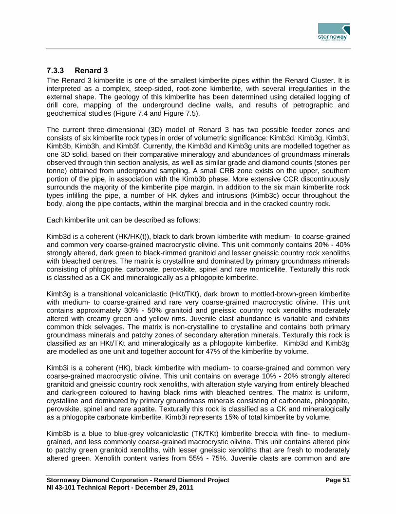
Stornoway Diamond Corporation - Renard Diamond Project Page 51 NI 43-101 Technical Report - December 29, 2011
7.3.3 Renard 3
The Renard 3 kimberlite is one of the smallest kimberlite pipes within the Renard Cluster. It is interpreted as a complex, steep-sided, root-zone kimberlite, with several irregularities in the external shape. The geology of this kimberlite has been determined using detailed logging of drill core, mapping of the underground decline walls, and results of petrographic and geochemical studies (Figure 7.4 and Figure 7.5). The current three-dimensional (3D) model of Renard 3 has two possible feeder zones and consists of six kimberlite rock types in order of volumetric significance: Kimb3d, Kimb3g, Kimb3i, Kimb3b, Kimb3h, and Kimb3f. Currently, the Kimb3d and Kimb3g units are modelled together as one 3D solid, based on their comparative mineralogy and abundances of groundmass minerals observed through thin section analysis, as well as similar grade and diamond counts (stones per tonne) obtained from underground sampling. A small CRB zone exists on the upper, southern portion of the pipe, in association with the Kimb3b phase. More extensive CCR discontinuously surrounds the majority of the kimberlite pipe margin. In addition to the six main kimberlite rock types infilling the pipe, a number of HK dykes and intrusions (Kimb3c) occur throughout the body, along the pipe contacts, within the marginal breccia and in the cracked country rock. Each kimberlite unit can be described as follows: Kimb3d is a coherent (HK/HK(t)), black to dark brown kimberlite with medium- to coarse-grained and common very coarse-grained macrocrystic olivine. This unit commonly contains 20% - 40% strongly altered, dark green to black-rimmed granitoid and lesser gneissic country rock xenoliths with bleached centres. The matrix is crystalline and dominated by primary groundmass minerals consisting of phlogopite, carbonate, perovskite, spinel and rare monticellite. Texturally this rock is classified as a CK and mineralogically as a phlogopite kimberlite. Kimb3g is a transitional volcaniclastic (HKt/TKt), dark brown to mottled-brown-green kimberlite with medium- to coarse-grained and rare very coarse-grained macrocrystic olivine. This unit contains approximately 30% - 50% granitoid and gneissic country rock xenoliths moderately altered with creamy green and yellow rims. Juvenile clast abundance is variable and exhibits common thick selvages. The matrix is non-crystalline to crystalline and contains both primary groundmass minerals and patchy zones of secondary alteration minerals. Texturally this rock is classified as an HKt/TKt and mineralogically as a phlogopite kimberlite. Kimb3d and Kimb3g are modelled as one unit and together account for 47% of the kimberlite by volume. Kimb3i is a coherent (HK), black kimberlite with medium- to coarse-grained and common very coarse-grained macrocrystic olivine. This unit contains on average 10% - 20% strongly altered granitoid and gneissic country rock xenoliths, with alteration style varying from entirely bleached and dark-green coloured to having black rims with bleached centres. The matrix is uniform, crystalline and dominated by primary groundmass minerals consisting of carbonate, phlogopite, perovskite, spinel and rare apatite. Texturally this rock is classified as a CK and mineralogically as a phlogopite carbonate kimberlite. Kimb3i represents 15% of total kimberlite by volume. Kimb3b is a blue to blue-grey volcaniclastic (TK/TKt) kimberlite breccia with fine- to medium-grained, and less commonly coarse-grained macrocrystic olivine. This unit contains altered pink to patchy green granitoid xenoliths, with lesser gneissic xenoliths that are fresh to moderately altered green. Xenolith content varies from 55% - 75%. Juvenile clasts are common and are

Stornoway Diamond Corporation - Renard Diamond Project Page 52 NI 43-101 Technical Report - December 29, 2011
both cored and uncored. The matrix is dominated by clinopyroxene, serpentine and clay, contributing to its blue-grey colour. Texturally this rock can be classified as a TKB and mineralogically as a phlogopite kimberlite. Kimb3b represents 17% of total kimberlite by volume. Kimb3h is a coherent (HK) black kimberlite with medium- to coarse-grained and rare, very coarse-grained macrocrystic olivine. This unit contains 15% - 25% strongly altered, dark green to black-rimmed granitoid and gneissic country rock xenoliths with bleached centres. The matrix is crystalline with primary groundmass minerals consisting of phlogopite, carbonate, spinel and perovskite. Texturally this rock is classified as a CK and mineralogically as a carbonate phlogopite kimberlite. Kimb3h represents 11% of total kimberlite by volume. Kimb3f is a volcaniclastic (TKt/HKt) brown to mottled green-blue kimberlite with medium-grained and common coarse-grained macrocrystic olivine. This unit contains 35% - 50% gneissic and granitoid country rock xenoliths, moderately altered with creamy yellow to green rims. Juvenile clasts with thick selvages are abundant, however, are commonly diffuse and are not always easily observed, particularly in darker, more magmatic zones. Autoliths of HK are abundant and, in general, this unit contains the highest percentage of autoliths compared to other units in the Renard 3 body. Texturally this rock is classified as a TKt/HKt and mineralogically as a phlogopite kimberlite. Kimb3f represents 10% of total kimberlite by volume. Coherent kimberlite also occurs in Renard 3 in the form of late-stage HK dykes and irregular intrusions (Kimb3c). They range in thickness from a few centimetres up to 20 m. Kimb3c is a black to dark-green HK with medium- to coarse-grained, and commonly, very coarse-grained macrocrystic olivine. This unit does not commonly contain country rock xenoliths, but where present, they comprises < 5% of the unit. CRB is found only in the southern, uppermost part of the pipe and therefore comprises only a minor portion of the entire kimberlite pipe. It has a maximum width of 45 m, wrapping around the southern end of the pipe, and extends vertically for almost 175 m. The kimberlite is surrounded from top to bottom by discontinuous CCR. The emplacement history of Renard 3 is complex and not fully understood at this time. However, textural features of the rocks, contact relationships and distribution of the rock types in the pipe suggest that Kimb3b and Kimb3f were emplaced early during pipe development, and Kimb3d, Kimb3g and Kimb3i were emplaced later.
7.3.4 Renard 4
The Renard 4 kimberlite is one of the larger kimberlite pipes within the Renard Cluster. It is interpreted as a diatreme-zone kimberlite with minor irregularities in the external shape. The geology of this kimberlite has been determined using detailed logging of drill core and mapping of the surface trench (Figure 7.4 and Figure 7.5). The Renard 4 pipe contains three kimberlite geological units: an MVK, referred to as Kimb4a, a transitional CK, referred to as Kimb4b, and a texturally complex MVK, referred to as Kimb4d. In the current 3D model there is also a unit referred to as FWR (further work required) on the eastern edge of the body that is currently unclassified. It may represent a more highly diluted Kimb4a or Kimb4d. A significant marginal CRB and CCR surround the main kimberlite. The

Stornoway Diamond Corporation - Renard Diamond Project Page 53 NI 43-101 Technical Report - December 29, 2011
Renard 4 CCR adjoins at depth with the CCR of Renard 9, along the southern margin of the pipe. In addition to the three main pipe infills, a number of HK dykes and irregular intrusions occur throughout the body, along the pipe contacts, within the marginal breccia and in the cracked country rock. Each kimberlite unit can be described as follows: Kimb4a is an MVK that can be further classified as a TKB. It is blue to green coloured with medium-grained and, less commonly, fine-grained macrocrystic olivine. A characteristic feature of this unit is that the olivine macrocrysts are commonly carbonatized, which is not typical of other Renard TKB’s. Juvenile clasts are common and are of both cored and uncored varieties. The unit contains 50% - 80% granitoid and gneiss country rock xenoliths that are fresh to moderately altered. The matrix is dominated by clay, serpentine carbonate and clinopyroxene, contributing to its blue-green colour. Kimb4a has been divided into two sub-types based on subtle differences in xenolith character and mineralogy: Kimb4a-1 is a blue-grey rock with fresh xenoliths and is mineralogically classified as a phlogopite monticellite kimberlite; Kimb4a-2 is a green rock with dark pink, hematized xenoliths that can be classified mineralogically as a phlogopite spinel monticellite kimberlite. Further work is required in order to determine if in fact these are two separate phases, or if the differences in the rock characteristics are due to variations within one phase. Kimb4a represents 71% of total kimberlite by volume. Kimb4b is a transitional volcaniclastic (HK/HKt/TKt), mottled light to dark brown kimberlite with medium- to coarse-grained macrocrystic olivine. Juvenile clasts are present and typically appear as diffuse magmatic domains within a more altered groundmass. Their abundance is variable and they exhibit thick selvages. Country rock xenoliths are fresh to more commonly, strongly altered granitoid and gneiss, with content ranging from 25% - 50%. The groundmass varies from crystalline to non-crystalline. Mantle nodules are very common and characterize this unit. Mineralogically this rock is classified as a perovskite monticellite phlogopite kimberlite. Kimb4b represents 25% of total kimberlite by volume. Kimb4d is a volcaniclastic to transitional (TK/TKt), dark blue kimberlite with medium-grained and, less commonly, fine- and coarse-grained macrocrystic olivine. It is a highly variable kimberlite texturally that contains common coherent (HK) and transitional coherent (HKt) intervals within an overall MVK texture. These more coherent zones occur as both dykes and possible autoliths of undiluted Kimb4d. Juvenile clasts are both uncored and cored varieties, some with diffuse margins. Country rock xenoliths are fresh to moderately altered granitoid and gneiss and represent 40% 75% of the rock. The matrix is dominated by serpentine, carbonate, clay minerals, clinopyroxene microlites and mica. Mantle indicator minerals are common and notably more abundant than in the other units. Mineralogically this rock can be classified as a phlogopite spinel monticellite kimberlite. Kimb4d represents 4% of total kimberlite by volume. Contacts between these rock types are sharp and commonly highlighted by HK dyke intrusions. Contrasting textural and component features described above and the sharp nature of the contacts, combined with the difference in diamond grade, supports interpretation of the three pipe infills as distinct rock-types emplaced during three separate volcanic events. The emplacement of Kimb4d is thought to have preceded that of Kimb4a based on the contact relationships between these two phases and the fact that Kimb4d appears as a remnant block of kimberlite that does not extend to depth. A second pipe kimberlite emplacement event resulted in the removal of a significant volume of Kimb4d and infilling of the diatreme by
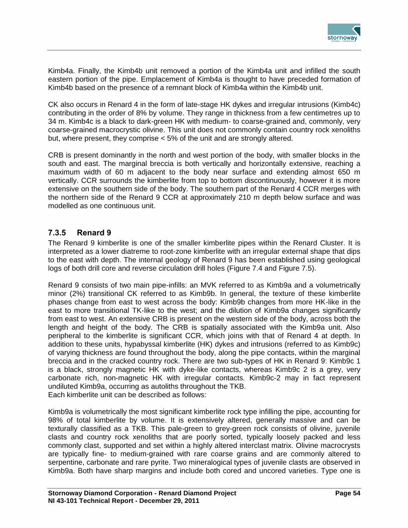
Stornoway Diamond Corporation - Renard Diamond Project Page 54 NI 43-101 Technical Report - December 29, 2011
Kimb4a. Finally, the Kimb4b unit removed a portion of the Kimb4a unit and infilled the south eastern portion of the pipe. Emplacement of Kimb4a is thought to have preceded formation of Kimb4b based on the presence of a remnant block of Kimb4a within the Kimb4b unit. CK also occurs in Renard 4 in the form of late-stage HK dykes and irregular intrusions (Kimb4c) contributing in the order of 8% by volume. They range in thickness from a few centimetres up to 34 m. Kimb4c is a black to dark-green HK with medium- to coarse-grained and, commonly, very coarse-grained macrocrystic olivine. This unit does not commonly contain country rock xenoliths but, where present, they comprise < 5% of the unit and are strongly altered. CRB is present dominantly in the north and west portion of the body, with smaller blocks in the south and east. The marginal breccia is both vertically and horizontally extensive, reaching a maximum width of 60 m adjacent to the body near surface and extending almost 650 m vertically. CCR surrounds the kimberlite from top to bottom discontinuously, however it is more extensive on the southern side of the body. The southern part of the Renard 4 CCR merges with the northern side of the Renard 9 CCR at approximately 210 m depth below surface and was modelled as one continuous unit.
7.3.5 Renard 9
The Renard 9 kimberlite is one of the smaller kimberlite pipes within the Renard Cluster. It is interpreted as a lower diatreme to root-zone kimberlite with an irregular external shape that dips to the east with depth. The internal geology of Renard 9 has been established using geological logs of both drill core and reverse circulation drill holes (Figure 7.4 and Figure 7.5). Renard 9 consists of two main pipe-infills: an MVK referred to as Kimb9a and a volumetrically minor (2%) transitional CK referred to as Kimb9b. In general, the texture of these kimberlite phases change from east to west across the body: Kimb9b changes from more HK-like in the east to more transitional TK-like to the west; and the dilution of Kimb9a changes significantly from east to west. An extensive CRB is present on the western side of the body, across both the length and height of the body. The CRB is spatially associated with the Kimb9a unit. Also peripheral to the kimberlite is significant CCR, which joins with that of Renard 4 at depth. In addition to these units, hypabyssal kimberlite (HK) dykes and intrusions (referred to as Kimb9c) of varying thickness are found throughout the body, along the pipe contacts, within the marginal breccia and in the cracked country rock. There are two sub-types of HK in Renard 9: Kimb9c 1 is a black, strongly magnetic HK with dyke-like contacts, whereas Kimb9c 2 is a grey, very carbonate rich, non-magnetic HK with irregular contacts. Kimb9c-2 may in fact represent undiluted Kimb9a, occurring as autoliths throughout the TKB. Each kimberlite unit can be described as follows: Kimb9a is volumetrically the most significant kimberlite rock type infilling the pipe, accounting for 98% of total kimberlite by volume. It is extensively altered, generally massive and can be texturally classified as a TKB. This pale-green to grey-green rock consists of olivine, juvenile clasts and country rock xenoliths that are poorly sorted, typically loosely packed and less commonly clast, supported and set within a highly altered interclast matrix. Olivine macrocrysts are typically fine- to medium-grained with rare coarse grains and are commonly altered to serpentine, carbonate and rare pyrite. Two mineralogical types of juvenile clasts are observed in Kimb9a. Both have sharp margins and include both cored and uncored varieties. Type one is

Stornoway Diamond Corporation - Renard Diamond Project Page 55 NI 43-101 Technical Report - December 29, 2011
classified as a spinel phlogopite kimberlite and type two as a spinel phlogopite monticellite kimberlite. This unit contains on average 60% - 75% fresh to moderately altered granitoid and gneissic country rock xenoliths set within a non-crystalline matrix comprising clays, serpentine and microlitic clinopyroxene. Kimb9b accounts for only 2% of total kimberlite by volume. The relative abundance of this rock type in the body, position and contact relationships suggest that Kimb9b is a remnant kimberlite phase emplaced before Kimb9a. This rock is a moderately altered, massive and texturally variable CK that displays both coherent and more rare volcaniclastic (i.e. TKB) textures. This brown kimberlite consists of olivine, country rock xenoliths and rare juvenile clasts that are poorly sorted and set within a dominantly crystalline groundmass. Olivine macrocrysts are medium- to coarse-grained. Juvenile clasts are relatively rare and, where observed, typically have diffuse margins. Groundmass minerals consist of perovskite, monticellite and phlogopite, set within an inhomogeneous, variably crystallized, interclast matrix dominated by carbonate, clays and microlitic clinopyroxene. This unit contains 20% - 50% moderately to strongly altered granitoid and gneissic country rock xenoliths. This rock exhibits textures of both MVK and a CK and can be classified mineralogically as a perovskite monticellite phlogopite kimberlite. The abundance and character of perovskite and phlogopite are diagnostic for this unit. Two types of HK occur in Renard 9; late-stage HK dykes (Kimb9c 1) and irregular intrusions or autoliths (Kimb9c 2). These are typically less than 1 m thick in drill core and range from black to dark green to grey coloured. Kimb9c 1 can be classified mineralogically as a phlogopite monticellite kimberlite and Kimb9c 2 can be classified as a phlogopite spinel monticellite kimberlite with extensive carbonate throughout. This unit does not commonly contain country rock xenoliths, but where present, they comprise < 5% of the unit and are strongly altered. The Renard 9 kimberlite has an extensive marginal CRB on the western and southern sides of the body, spatially associated with Kimb9a. It has a surface width of approximately 30 m and extends the full depth of the body. Contacts between this and the Kimb9a unit are typically gradational. Peripheral CCR with rare HK dykes discontinuously surrounds the kimberlite and joins with the CCR of Renard 4 at depth
7.3.6 Renard 65
The Renard 65 kimberlite is the largest kimberlite in the Renard Cluster. It is interpreted as a diatreme-zone kimberlite with a slightly irregular shape at surface, and tapering gradually with depth. The internal geology of this kimberlite has been determined using geological logs of both core and reverse circulation drill holes and in a preliminary fashion using examination of field logs of drill core (Figure 7.6). Renard 65 consists of four main pipe-infilling kimberlite units: Kimb65a, Kimb65b, Kimb65d and Kimb65e. In addition, CRB and CCR surround the main kimberlite pipe infills. In the current 3D geological model, Kimb65e was modelled with Kimb65a as its distribution was such that it was hard to group it in 3D, suggegsting that it was a remnant unit in Kimb65a. In addition, a number of HK dykes and irregular intrusions (Kimb65c) occur throughout the body as late-stage intrusions along the pipe contacts and within the CRB and CCR. Each kimberlite unit can be described as follows:

Stornoway Diamond Corporation - Renard Diamond Project Page 56 NI 43-101 Technical Report - December 29, 2011
Kimb65a is a pale blue-grey to green-grey volcaniclastic (TK/TKt) kimberlite breccia with fine- to medium-grained and, less commonly, coarse-grained macrocrystic olivine. This unit contains 50% 75% fresh to altered, pink to patchy-green-coloured granitoid xenoliths, with lesser amounts of gneiss. Juvenile clasts are common and are both cored and uncored. Mineralogically this rock can be classified as a phlogopite kimberlite, and contributes 78% by volume to the kimberlite. Kimb65b is a coherent (HK/HKt) black to dark brown kimberlite with coarse to very coarse-grained macrocrystic olivine. This unit contains 5% 35% strongly altered, dark-green to black-rimmed gneissic and lesser granitoid country rock xenoliths. Mantle nodules are abundant and include harzburgite, peridotite and possible minor dunite types. The matrix is crystalline with minor patches of alteration from the digestion of country rock xenoliths. Kimb65b represents 8% of the kimberlite by volume. Kimb65d is a volcaniclastic (HKt/TKt) light to dark brown, occasionally mottled green kimberlite with medium- to coarse-grained and, rarely, very coarse-grained macrocrystic olivine. This unit contains 30% - 50% (may reach up to 70%) granitoid and gneissic country rock xenoliths. These are moderately altered with pale green and yellow rims. Juvenile clasts are present, are both cored and uncored, and are typically < 3 cm in size. HK autoliths are also present and are round with sharply defined margins. The matrix varies from crystalline to non-crystalline, with patchy zones of secondary alteration. Kimb65d represents about 14% by volume. .. Kimb65e is a complex, volcaniclastic to coherent (HKt), dark-brown kimberlite with medium- to coarse-grained macrocrystic olivine. This unit contains 25% - 55% gneissic and granitoid country rock xenoliths (granite may dominate), fresh to moderately altered pale green, with stronger alteration in smaller xenocrysts. The matrix is crystalline to patchy crystalline with alteration minerals from xenolith digestion. The primary groundmass mineralogy includes phlogopite, carbonate, spinel and perovskite. Due to the irregular nature of the contacts, Kimb65e is currently modelled in Kimb65b. The HK dykes (Kimb65c) that occur in Renard 65 drill core range in thickness from a few centimetres up to 35 m. Kimb65c is a coherent black to dark-green kimberlite with medium- to coarse-grained and, commonly, very coarse-grained macrocrystic olivine. This unit does not commonly contain country rock xenoliths, but where present, they comprise < 5% of the unit. Renard 65 kimberlite is surrounded by extensive CRB and CCR units that extend to depth but are discontinuous around the pipe. CRB is dominant on the western side of the body whereas CCR dominates on the east and north sides.

Stornoway Diamond Corporation - Renard Diamond Project Page 57 NI 43-101 Technical Report - December 29, 2011
Figure 7.6: Plan and Section Views: Renard 65, Lynx and Hibou

Stornoway Diamond Corporation - Renard Diamond Project Page 58 NI 43-101 Technical Report - December 29, 2011
7.3.7 Other Renard Kimberlite Pipes
The remaining Renard kimberlite pipes (Renard 1, Renard 7, Renard 8 and Renard 10) are currently not part of the economic assessment but are included in the following summary as future work may be undertaken on these bodies. Plan and Section views are shown in Figure 7.7 and Figure 7.8. Renard 1 The Renard 1 kimberlite is the second largest kimberlite in the Renard Cluster. It is interpreted as a diatreme-zone kimberlite with a slightly irregular shape at surface, and tapering gradually with depth. The geology of this kimberlite has been determined in a preliminary fashion using 11 drill cores. A twelfth hole (537 m), completed in 2010, crossed the body from south to north at an inclination of -58° and intersected kimberlite CRB and CCR from 195 to 508 m downhole, and supports the model shown in Figure 7.7 and Figure 7.8. At the present time insufficient diamond data exists to allow the classification of Renard 1 as a resource. Renard 1 consists of three main pipe-infilling kimberlite units: an MVK referred to as Kimb1a (comprising 61% of total kimberlite); a transitional CK referred to as Kimb1b (comprising 27% of total kimberlite) and a large, irregular HK intrusion referred to as Kimb1c (comprising 11% of total kimberlite). It is unclear at this time how these kimberlites relate temporally, and whether or not they represent a textural change within one kimberlite phase or are three distinct phases. In addition to these main infills, a CRB and CCR almost completely surround the main kimberlite pipe infills. The CRB is much larger on the western side of the body and the CCR is much larger on the eastern side. These are extensive and extend to depth in the kimberlite, however are discontinuous around the pipe. A number of HK dykes and irregular intrusions occur throughout the main phases of kimberlite, along the pipe contacts and within the marginal CRB and CCR units. These are also referred to as Kimb1c because at this time they cannot be distinguished geologically from HK in the large intrusion when examining drill core.

Stornoway Diamond Corporation - Renard Diamond Project Page 59 NI 43-101 Technical Report - December 29, 2011
Figure 7.7: Plan View – Renard 1, Renard 7, Renard 8 and Renard 10
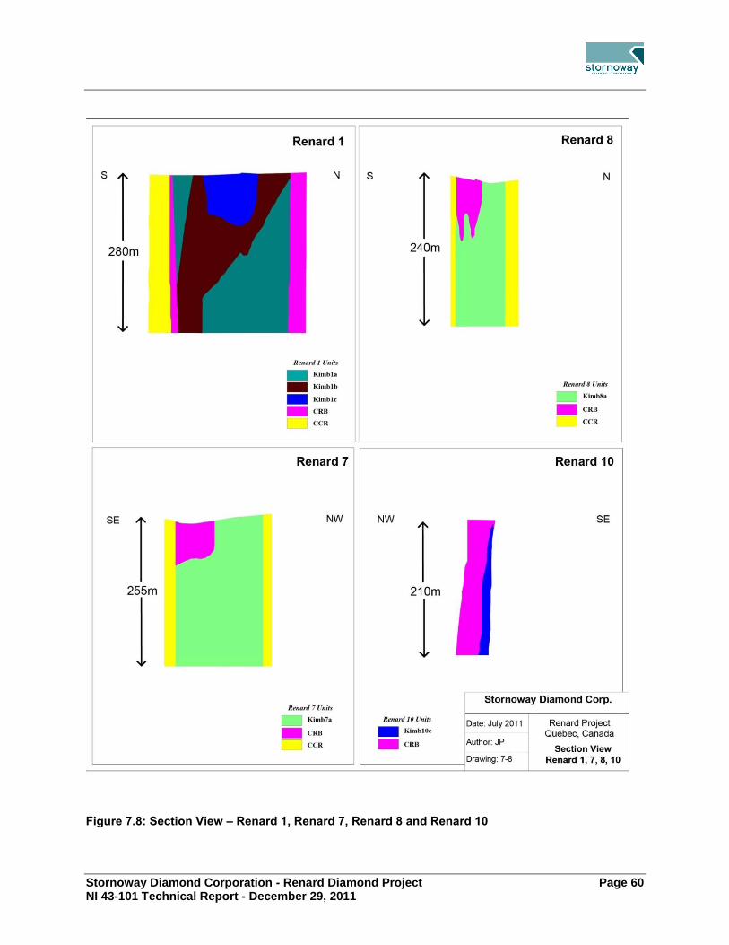
Stornoway Diamond Corporation - Renard Diamond Project Page 60 NI 43-101 Technical Report - December 29, 2011
Figure 7.8: Section View – Renard 1, Renard 7, Renard 8 and Renard 10

Stornoway Diamond Corporation - Renard Diamond Project Page 61 NI 43-101 Technical Report - December 29, 2011
Renard 7 The Renard 7 kimberlite is a moderate to large sized kimberlite in the Renard Cluster. It is interpreted as a diatreme-zone kimberlite with a slightly irregular shape at surface, and tapering gradually with depth. The geology of this kimberlite has been determined in a preliminary fashion using seven drill holes. The current 3D model of Renard 7 consists of two main pipe-infilling kimberlite units: a highly diluted grey-green MVK that is referred to as Kimb7a and is classified as TKB; and an extensive amount of HK localized in the upper southern portion of the body referred to as Kimb7c. However it is unclear at this time if this HK represents a main pipe infilling event. In the current 3D model, separate phases of kimberlite were not modelled, therefore their relative abundances are unknown. CCR almost completely surrounds the main kimberlite pipe infills along with a CRB block located in the southeast. This CRB is more internal than marginal to the Kimb7a unit. Additional, smaller but significant zones of CRB are also noted within the Kimb7a unit. A number of HK dykes and irregular intrusions occur throughout the body, along the pipe contacts, within the marginal breccia and in the cracked country rock. These are also referred to as Kimb7c because at this time they cannot be distinguished geologically from HK in the large intrusion. Renard 8 The Renard 8 kimberlite is one of the smallest kimberlite pipes within the Renard Cluster. It is interpreted as a steep-sided diatreme-zone kimberlite with a regular external shape. The geology and geomoetry of this kimberlite has been determined in a preliminary fashion using ten drill holes. The current 3D model of Renard 8 consists of one main pipe infill kimberlite unit: a highly diluted grey-green MVK that is classified as TKB, referred to as Kimb8a. In addition, CCR completely surrounds the main kimberlite pipe infills along with a CRB block located in the south. The CRB is more internal than marginal to the kimberlite. In addition, a number of HK dykes and intrusions referred to as Kimb8c occur throughout the body, along the pipe contacts, within the marginal breccia and in the cracked country rock. Renard 10 The Renard 10 kimberlite is the smallest “pipe” within the Renard Cluster. It cannot technically be classified as a pipe per se, as its morphology is more dyke-like. However, the kimberlite (17% of the body by volume) in this body is surrounded by a significant marginal CRB (83% of the body by volume). This is a feature that has not been noted to be associated with other large dykes on the Foxtrot property. Only five diamond drill holes have been completed to date on Renard 10 and it is on this data that these preliminary interpretations are based. The kimberlite in Renard 10 is classified as HK and the morphology of this HK is dyke-like. Kimberlite represents 17% of the modelled body by volume and is typically undiluted. Contacts between this HK and the adjacent CRB are sharp. The CRB has an overall appearance and texture similar to that of the other Renard bodies. This, and the presence of the extensive CRB associated with the relatively small amount of kimberlite suggests that Renard 10 may actually represent a blind intrusion.

Stornoway Diamond Corporation - Renard Diamond Project Page 62 NI 43-101 Technical Report - December 29, 2011
7.3.8 Lynx and Hibou Kimberlite Dykes
Lynx Kimberlite Dyke The Lynx dyke consists of CK that can be further classified as HK. Trenching and mapping of Lynx and the logging of 73 drill holes reveals that the dyke comprises semi-continuous thick intersections of kimberlite with many thin (from < 1 cm to 40 cm) discrete sheets adjacent to it. Lynx extends for a minimum of 4.2 km along strike and has a variable dip (10o to 50o) to the east. The dyke may reach cumulative thicknesses of up to 3 m, however the average thickness is 1.8 m. The main kimberlite intersection appears to pinch and swell and, where thin, is strongly altered and replaced by clays. Overall, Lynx displays varying levels of alteration, often showing zonation with portions of the main intersection being highly altered and friable on one half, but massive and relatively unaltered in the other. Fracturing is present throughout the dykes and varies in intensity (Figure 7.6). Macroscopically, the Lynx HK is dark grey to green coloured, strongly magnetic and consists of two generations of olivine (macrocrysts and phenocrysts) set in a carbonate rich groundmass. Olivine macrocrysts are medium- to coarse-grained with common, very coarse grains and are completely serpentinized. Olivine comprises 40% - 50% of the rock, however local variations range from 10% 90%. Olivine megacrysts and olivine dominated mantle nodules larger than 10 cm are present. Mantle indicator minerals are very common throughout this HK, representing up to 3% of the rock by volume and include coarse- to very coarse-grained picroilmenite, chrome diopside and pyrope garnet. Country rock xenoliths are rare, representing less than 2% of the rock. Xenoliths are rounded to sub-rounded and are strongly altered granitoid or gneiss fragments. Contacts with the surrounding country rock are marked in the kimberlite by local minor fracturing and sometimes extensive carbonate veining. Chilled margins with flow aligned olivine macrocrysts are common and typically less than 5 mm in width. Fracturing parallel to the contact, and joints perpendicular to the contact, are present within the country rock and decrease in intensity away from the contact. The Lynx dyke typically cuts the foliation of the country rock. Microscopically, the Lynx HK consists of olivine macrocrysts and phenocrysts and evenly distributed, crystalline groundmass dominated by carbonate, serpentine and phlogopite with an average modal for carbonate of 15% - 35%. Olivine are completely pseudomorphed to a pale-yellow green serpentine and more rarely carbonatized, and commonly show a preferred orientation with their long axes sub-parallel to the dyke margins. Groundmass minerals consist of carbonate, phlogopite, monticellite, serpentine and ilmenite with minor dolomite. Accessory minerals (5% modal) include perovskite, spinel and apatite. Distinctive magmatic textures are observed in Lynx, where calcite occurs as millimetre scale oikocrysts that enclose small olivine and other matrix minerals (Patterson et al., 2009). Hibou Kimberlite Dyke The Hibou dyke is a CK that can be further classified as an HK. Hibou consists of one main kimberlite intersection with thin HK veins and dykes (from 1 cm to 30 cm) adjacent to the main intersection. Trenching and mapping of Hibou and the logging of 35 drill holes reveals that the HK may reach up to 3.5 m thick, but is on average 2 m thick. The dyke has a west-northwest strike extent of at least 850 m with a shallow dip of approximately 10o to the north-northeast. It is open, down dip and along strike to the northwest. The HK pinches and swells and, where thin, is
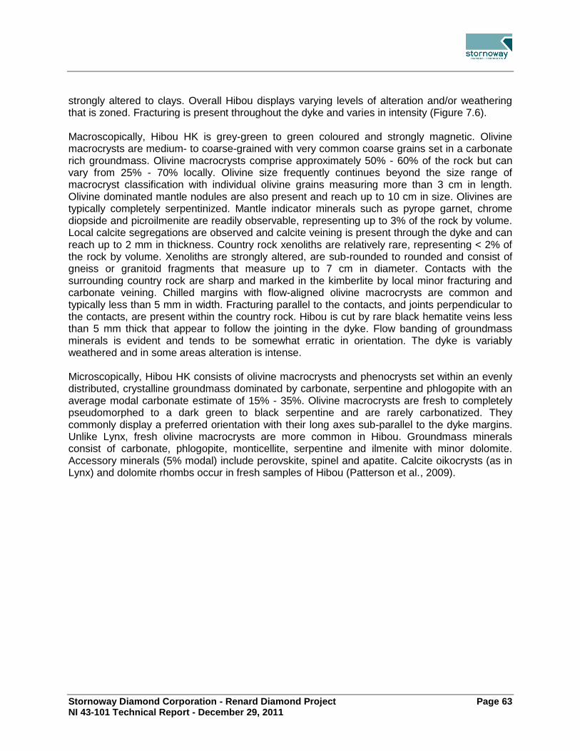
Stornoway Diamond Corporation - Renard Diamond Project Page 63 NI 43-101 Technical Report - December 29, 2011
strongly altered to clays. Overall Hibou displays varying levels of alteration and/or weathering that is zoned. Fracturing is present throughout the dyke and varies in intensity (Figure 7.6). Macroscopically, Hibou HK is grey-green to green coloured and strongly magnetic. Olivine macrocrysts are medium- to coarse-grained with very common coarse grains set in a carbonate rich groundmass. Olivine macrocrysts comprise approximately 50% - 60% of the rock but can vary from 25% - 70% locally. Olivine size frequently continues beyond the size range of macrocryst classification with individual olivine grains measuring more than 3 cm in length. Olivine dominated mantle nodules are also present and reach up to 10 cm in size. Olivines are typically completely serpentinized. Mantle indicator minerals such as pyrope garnet, chrome diopside and picroilmenite are readily observable, representing up to 3% of the rock by volume. Local calcite segregations are observed and calcite veining is present through the dyke and can reach up to 2 mm in thickness. Country rock xenoliths are relatively rare, representing < 2% of the rock by volume. Xenoliths are strongly altered, are sub-rounded to rounded and consist of gneiss or granitoid fragments that measure up to 7 cm in diameter. Contacts with the surrounding country rock are sharp and marked in the kimberlite by local minor fracturing and carbonate veining. Chilled margins with flow-aligned olivine macrocrysts are common and typically less than 5 mm in width. Fracturing parallel to the contacts, and joints perpendicular to the contacts, are present within the country rock. Hibou is cut by rare black hematite veins less than 5 mm thick that appear to follow the jointing in the dyke. Flow banding of groundmass minerals is evident and tends to be somewhat erratic in orientation. The dyke is variably weathered and in some areas alteration is intense. Microscopically, Hibou HK consists of olivine macrocrysts and phenocrysts set within an evenly distributed, crystalline groundmass dominated by carbonate, serpentine and phlogopite with an average modal carbonate estimate of 15% - 35%. Olivine macrocrysts are fresh to completely pseudomorphed to a dark green to black serpentine and are rarely carbonatized. They commonly display a preferred orientation with their long axes sub-parallel to the dyke margins. Unlike Lynx, fresh olivine macrocrysts are more common in Hibou. Groundmass minerals consist of carbonate, phlogopite, monticellite, serpentine and ilmenite with minor dolomite. Accessory minerals (5% modal) include perovskite, spinel and apatite. Calcite oikocrysts (as in Lynx) and dolomite rhombs occur in fresh samples of Hibou (Patterson et al., 2009).

Stornoway Diamond Corporation - Renard Diamond Project Page 64 NI 43-101 Technical Report - December 29, 2011
8.0 DEPOSIT TYPES There are two types of diamond deposits: primary and secondary. Primary deposits are those in which the diamonds remain inside the original host rock (usually kimberlite) that conveyed them to the surface. Secondary deposits are formed when the diamonds are eroded from the host rock and concentrated by the action of water into alluvial deposits (in rivers) or marine deposits (in beaches). The Renard kimberlites are primary deposits.
Overview of Primary Diamond Deposits 8.1.Primary diamond deposits such as kimberlites and lamproites have produced over 50% of the world’s diamonds. The remainder was derived from recent to ancient placer deposits that originated from the erosion of kimberlite and/or lamproite. Although diamondiferous kimberlite and lamproite comprise most of the economic diamond deposits, other diamond-bearing rocks have also been discovered and are the subject of numerous academic papers. Such diamond-bearing rocks include ultramafic lamprophyres (aillikites) in Canada and volcaniclastic komatiites in French Guiana (Capdevila et al., 1999). It has been established by the scientific community that diamonds are not genetically related to kimberlite or lamproite but that kimberlite and lamproite intrusives serve as a transport mechanism for bringing diamonds to surface (Kirkley et al., 1991) from the mantle. Clifford (1966) and Janse (1991) stated that a majority of economic diamondiferous kimberlites occur in stable Archaean age cratonic material that has not undergone any thermal or deformational event since 2.5 Ga. Such Archaean age cratons include the Kaapvaal, Congo and West African cratons (Africa), Superior and Slave Provinces (Canada), East European Craton (Russia, Finland), and the West, North and South Australian cratons. The only exceptions to date are the Argyle and Ellendale mines of Australia, which occurred in Proterozoic-age, remobilized, cratonic material. To date, over 6,000 known kimberlite and lamproite occurrences have been discovered, of which over 1,000 are diamondiferous. Some of the well-known diamondiferous kimberlites/lamproites currently being mined include Argyle (lamproite) in Australia; Orapa and Jwaneng (kimberlites) in Botswana; Jubilee, Udachnaya and Mir (kimberlites) in Russia; Venetia (kimberlite) in South Africa, and the Ekati and Diavik clusters (kimberlites) in Canada. Economic diamond kimberlite and/or lamproite pipes generally range from less than 0.4 ha to 146 ha in surface area, with the maximum size being more than 200 ha (for example, Catoca, Angola). Economic diamond grades can range from 3.5 cpht to 600 cpht.
Kimberlite-Hosted Deposits 8.2.Much of the following discussion of kimberlite types and deposits is taken directly from a publication on ore deposit models by Mitchell (1991). Kimberlites remain the principal source of primary diamonds despite the discovery of high-grade deposits in lamproites. Recent mineralogical and Rb–Sr isotopic studies have shown that two varieties of kimberlite exist:

Stornoway Diamond Corporation - Renard Diamond Project Page 65 NI 43-101 Technical Report - December 29, 2011
Group 1, or olivine-rich monticellite serpentine calcite kimberlites; and
Group 2, or micaceous kimberlites (predominantly occur in southern Africa).
“Group 1” kimberlites are complex, hybrid rocks consisting of minerals that may be derived from:
Fragmentation of upper mantle xenoliths (including diamond);
Megacryst or discrete nodule suite; or
Primary phenocrysts and groundmass minerals.
The contribution to the overall mineralogy from each source varies widely and significantly influences the petrographic character of the rocks. Consequently, Group 1 kimberlites comprise a petrological clan of rocks that exhibit wide differences in appearance and mineralogy as a consequence of the above variation, coupled with differentiation and diverse styles of emplacement of the magma. Currently, three textural-genetic groups of kimberlite are recognized, each being associated with a particular style of magmatic activity in such a system. These are:
Crater facies;
Diatreme facies; and
Root Zone facies.
Rocks belonging to each facies differ in their petrology and primary mineralogy, but may contain similar xenocrystal and megacrystal assemblages. With a few exceptions, such as the Finsch Kimberlite Mine in the Republic of South Africa and the Dokolwayo Kimberlite Mine in Swaziland, most of the well-known diamondiferous kimberlites in South Africa and elsewhere are Group 1 kimberlites. The Renard kimberlites are considered to be Group 1 kimberlites. The Renard kimberlites are interpreted to be steep-sided, pipe-like structures with irregular to elongate shapes in plan view. Surface expressions of the kimberlite vary between 0.1 ha and 2.0 ha although there are larger haloes of broken country rock. The Renard Cluster is mainly composed of diatreme-like kimberlitic breccia lithologies and hypabyssal kimberlitic material. No crater material is noted in the Renards. The Lynx, Hibou, North Anomaly, Southeast Anomaly and G04-296 hypabyssal dykes are interpreted to be intrusions of kimberlitic material that did not vent to the earth’s surface at the time of emplacement.

Stornoway Diamond Corporation - Renard Diamond Project Page 66 NI 43-101 Technical Report - December 29, 2011
9.0 EXPLORATION All exploration has been carried out by Stornoway Diamond Corporation (Stornoway).
Geological Mapping 9.1.Structural geological mapping was undertaken in the area of the Lynx dyke in 2004, and over the Renard bodies in 2006 and 2010. The objective of the mapping programs of 2004 and 2006 was to identify structural controls that could help locate more kimberlitic intrusions or dykes. The program results proved to be inconclusive. It was noted, however, that the rock fracturing intensity increased near the kimberlitic bodies. The objective of the geological mapping in October 2010 was to identify large-scale feature of interest (ie. faults, shear zones) interpreted from geophysical data and aerial photographs. Overburden in targeted areas was cleared to expose the bedrock for mapping. The program was successful in highlighting two large faults and two smaller ones within the proposed mine site. Sampling trenches were excavated on Renard 4, Renard 65, Lynx, Hibou, and the North Anomaly. Each trench was mapped in detail prior to sampling. Mapping was undertaken with grid control and reference points were surveyed by a registered surveyor. Mapping notes were made on the contacts and included the mineralogy, relationship of the dyke to the host rock, and structural measurements in the host rocks. Plan and section maps were completed for the majority of the trenches. During the underground bulk sampling program at Renard 2 and Renard 3, geological mapping was completed on all workings. The face was mapped after each round during the development of the ramp and drifts and, after the underground excavation was completed, the ramp and drift walls were mapped in the kimberlites
Heavy Mineral Sampling 9.2.Since the inception of the Foxtrot Project, approximately 12,000 heavy mineral samples have been collected over a 400,000 km2 area of which some 8,140 lie within the current land holdings. Heavy mineral samples collected to date are summarized by year in Table 9.1. This work has been reported in previous technical reports (Clements and O’Connor, 2001, 2002; Lucas et al., 2003; Lépine and O’Connor, 2004; O’Connor and Lépine, 2005, 2006).

Stornoway Diamond Corporation - Renard Diamond Project Page 67 NI 43-101 Technical Report - December 29, 2011
Table 9.1: Heavy Mineral Sampling
Year Foxtrot Property
Number of Samples Comments
1996–1999 13 Regional samples within the area that became the Foxtrot
Property
2000 48 One sample collected during this program yielded a highly
anomalous indicator mineral count
2001 252 Completed to further define mineral trains and to prioritize
geophysical anomalies for drilling
2002 785 Collected to define existing mineral trains and to increase
the sample density within the property
2003 914 Collected along detailed grids with dense sample spacing
and as wider spaced, reconnaissance samples
2004 2,000 Collected along detailed grids with dense sample spacing
and as wider spaced, reconnaissance samples
2005 1,412 Collected along detailed grids with dense sample spacing
and as wider spaced, reconnaissance samples
2006 1,203 Collected along detailed grids with dense sample spacing
and as follow up samples
2007 959 Collected along detailed grids with dense sample spacing
and as follow up samples
2008 554 Collected along detailed grids with dense sample spacing
and as follow up samples
Totals 8,140
Geophysical Surveys 9.3.Since 2000, several ground and airborne geophysical surveys were completed on the Foxtrot Property. This work has been reported in previous technical reports (Clements and O’Connor, 2001, 2002; Lucas et al., 2003; Lépine and O’Connor, 2004; O’Connor and Lépine, 2005, 2006). Geophysical surveys that have been completed to the effective date of this report are summarized in Table 9.2.

Stornoway Diamond Corporation - Renard Diamond Project Page 68 NI 43-101 Technical Report - December 29, 2011
Table 9.2: Geophysical Surveys
Year Airborne Geophysical
Surveys (total line km)
Number of Ground
Magnetic Surveys
(total line km)
Number of Electromagnetic
Surveys (total line km)
2000 1,419 0 (0) 0 (0)
2001 5 (38.4) 0 (0)
2002 900 21 (140.5) 14 (20.9)
2003 8,900 52 (452.3) 10 (19.4)
2004 4,778 58 (505.4) 33 (67.7)
2005 19,491 25 (215.2) 41 (84.2)
2006 29 (308.0) 51 (81.6)
2007 52 (441.5) 43 (41.9)
2008 1,969 32 (385.0) 12 (11.8)
Totals 37,457 274 (2,486.3) 204 (327.5)
Drilling 9.4.Drilling is discussed in Section 10.0.
Sampling for Diamonds 9.5.Three basic levels of progressively larger diamond sampling procedures are summarized below (caustic fusion sampling, mini-bulk sampling and bulk sampling), followed by descriptions of the comparable core, reverse circulation, trenching and underground sample programs.
9.5.1 Caustic Fusion Sampling
The caustic fusion process is used to evaluate, characterize and correlate the diamond potential of individual kimberlite lithologies, and to provide data to facilitate the grade estimation process. The objective of this type of test is to extract all diamonds greater than 0.1 mm in size, through chemical dissolution of the host rock sample. Individual samples may vary in size from a few kilograms to hundreds of kilograms, depending on the available material and the specific purpose of the testing. Kimberlite may be collected from drill core, float boulders, subcrop, outcrop, underground exposures and subsamples of material in a process facility or a

Stornoway Diamond Corporation - Renard Diamond Project Page 69 NI 43-101 Technical Report - December 29, 2011
combination thereof. Individual sample results from comparable kimberlite units may be merged together to provide larger, statistically more representative, samples. Kimberlite is collected, described and recorded by the site geologists following protocols in place at the time. Samples are individually numbered, weighted, sealed in a tamper-resistant container appropriate for the volume of material, and transported to the test facility by a combination of charter aircraft and commercial couriers.
9.5.2 Mini-Bulk Sampling
Although there is no formal industry-accepted definition of a ‘mini-bulk’ sample, many companies would agree that the term is generally used to refer to the processing of kimberlite material up to several tens of tonnes. This material may be derived from drill core, RC chips, boulders, subcrop, outcrop, trenches or underground workings. Mini-bulk samples are usually processed through Dense Media Separation (DMS) equipment that, depending on specifications and diamond recovery objectives of a particular program, may be configured to recover diamonds of greater than 0.5 mm, 0.85 mm or 1.18 mm on square-mesh screens. In some cases caustic dissolution or other extraction techniques may be utilized to recover the diamonds. All of Stornoway’s mini-bulk samples reported herein were processed through DMS equipment, and the reported diamond content is based upon stones retained on either 1.18 mm square-mesh screens or +1 DTC screens. Stornoway’s mini-bulk sampling programs reported herein have used drill core, RC chips, boulders, and surface trenches to source kimberlite material. Drill core was collected, described and recorded by the site geologists following protocols in place at the time. Core boxes were sealed, weighted and secured to pallets for shipping, then forwarded to the North Vancouver laboratory facilities. Upon receipt samples were verified, then composited and processed through an onsite DMS plant. The mini-bulk sample data has not been used for mineral resource estimating. During the various RC drill programs (see Section 10), screen openings of either 0.98 mm or 1.18 mm were used to dewater the RC kimberlite chip recovery flow and to remove the undersize fraction. Recovered kimberlite was separated at regular downhole intervals into individual samples and collected in either large 1.5 t bulk sample bags or individually lined 205 l steel drums. Bulk bags and/or drums were clearly identified with a unique numbering system, fastened with tamper-proof seals and transported to secured Stornoway storage facilities. Charter aircraft and bonded freight services were organized as required to transport sample materials to the process facility. In 2004, RC mini-bulk samples were dispatched to the external Thunder Bay Mineral Processing Laboratory (TBMPL) in Ontario for DMS processing, whereas RC mini-bulk samples from 2006 were sent to Stornoway’s North Vancouver laboratory and those from 2007 were processed by the Lagopède-based DMS.
9.5.3 Bulk Sampling
Although there is no formal industry-accepted definition of a ‘bulk’ sample, many companies would agree that the term is generally used to refer to the processing of kimberlite material exceeding several tens of tonnes. This material may be derived from drill core, RC chips, boulders, subcrop, outcrop, trenches or underground workings. Bulk samples are usually

Stornoway Diamond Corporation - Renard Diamond Project Page 70 NI 43-101 Technical Report - December 29, 2011
processed through DMS equipment that, depending on specifications and diamond recovery objectives of a particular program, may be configured to recover diamonds of greater than 0.85 mm or 1.18 mm on square-mesh screens. In some cases larger screen sizes or other extraction techniques may be utilized for diamond recovery. All of Stornoway’s bulk samples reported herein comprise either surface trench or underground sample material, and were processed through DMS equipment. The reported diamond content is based upon stones retained on either 1.18 mm square mesh or +1 DTC screens. To maintain the integrity of the bulk samples, a sampling protocol was established before the exploration work took place in order to ensure that the final diamond recovery data can be linked to the correct kimberlite, sample location within the body and rock type. Each surface or underground round was assigned a sample number and a colour code by the mine geologist. For surface samples, individual loads were directed to specific dump piles in a secure, access-controlled, storage area located near the DMS facility. The storage area was monitored 24 hours per day by an independent security force (Groupe Canaprobe of Montréal, Québec) and by CCTV surveillance. For underground samples, a sample number placard was posted in the remuck bay and on the dump truck so the underground operators and process plant staff were constantly aware of which sample was being handled. On surface, a member of the DMS staff at the controlled access storage site directed the loads to the correct stockpile locations and kept a log of loads that were delivered from underground. Once all loads were hauled to surface, the mine geologist checked that the remuck bay was cleaned out in preparation for the next sample. Sample number placards were taken to the surface with the final dump truck load and placed on the appropriate stockpile. A location plan of the surface or underground samples was updated each time a new pile was initiated, in order to easily identify sample location.
9.5.4 Core Sampling
Certain drill core collected during historical drill programs (discussed in Section 10) was composited and treated for macrodiamond recovery. Results are summarized in Table 9.3.
Table 9.3: Summary of Macrodiamond Sampling Results
Kimberlite Body Sample Type Year
Collected
Number of
Samples
Total Weight
(t)
Total Carats
(+1 DTC/+1.18
Tyler)
Renard 1 Drill Core 2002 1 0.3 0.00
Renard 1 Drill Core 2003 11 10.0 0.58
Renard 2 Drill Core 2002 7 4.9 2.89
Renard 2 Drill Core 2003 8 8.6 4.53
Renard 2 Drill Core 2004 9 11.5 13.30

Stornoway Diamond Corporation - Renard Diamond Project Page 71 NI 43-101 Technical Report - December 29, 2011
Kimberlite Body Sample Type Year
Collected
Number of
Samples
Total Weight
(t)
Total Carats
(+1 DTC/+1.18
Tyler)
Renard 2 Drill Core 2005 16 6.7 4.75
Renard 2 Drill Core 2006 7 2.8 2.47
Renard 2 RC Chips 2004 12 171.2 145.38
Renard 2 RC Chips 2007 15 86.8 70.95
Renard 2 Underground 2006/2007 15 2448.8 1601.94
Renard 3 Drill Core 2002 5 4.9 6.47
Renard 3 Drill Core 2004 13 13.7 13.70
Renard 3 RC Chips 2004 10 157.0 184.53
Renard 3 RC Chips 2007 13 59.4 34.86
Renard 3 Underground 2006/2007 13 2113.7 2799.85
Renard 4 Drill Core 2002 6 4.8 2.94
Renard 4 Drill Core 2003 15 12.4 5.32
Renard 4 Drill Core 2004 36 32.3 13.62
Renard 4 Drill Core 2005 1 0.5 0.48
Renard 4 RC Chips 2004 17 141.8 52.57
Renard 4 RC Chips 2006 14 41.4 34.67
Renard 4 Surface Sample 2004 2 1.8 3.09
Renard 4 Surface Sample 2005 6 9.8 17.27
Renard 4 Surface Sample 2006/2007 7 2104.2 2721.88
Renard 65 Drill Core 2002 2 0.8 1.19
Renard 65 Drill Core 2003 23 19.8 8.29
Renard 65 Drill Core 2004 22 17.8 4.05
Renard 65 RC Chips 2004 18 147.2 32.49

Stornoway Diamond Corporation - Renard Diamond Project Page 72 NI 43-101 Technical Report - December 29, 2011
Kimberlite Body Sample Type Year
Collected
Number of
Samples
Total Weight
(t)
Total Carats
(+1 DTC/+1.18
Tyler)
Renard 65 Surface Sample 2007 2 266.0 51.77
Renard 7 Drill Core 2005 4 4.1 0.10
Renard 8 Drill Core 2005 4 6.1 0.47
Renard 9 Drill Core 2004 6 6.0 5.56
Renard 9 Drill Core 2005 4 6.2 6.24
Renard 9 RC Chips 2006 19 70.3 34.09
Renard 9 RC Chips 2007 5 27.3 11.97
Hibou Surface Sample 2005 5 19.8 4.58
Hibou Surface Sample 2006 2 31.4 38.52
Hibou Surface Sample 2008 1 543.9 781.41
Lynx Surface Sample 2003 3 3.9 3.67
Lynx Surface Sample 2004 2 10.3 14.47
Lynx Surface Sample 2005 6 34.7 40.40
Lynx Surface Sample 2007 3 494.3 528.93
North Anomaly Surface Sample 2006/2008 2 46.4 43.00

Stornoway Diamond Corporation - Renard Diamond Project Page 73 NI 43-101 Technical Report - December 29, 2011
9.5.5 Reverse Circulation (RC) Sampling
RC chip sampling programs on the Renard Project were undertaken with objectives that varied over time from simply collecting a large amount of kimberlite to create representative samples, to characterizing the grade over various depth intervals, to regular sampling intervals. Early work on the Project also considered that some minimum quantity of kimberlite should comprise each sample to accommodate processing. The data set of sampling results represents:
Sampling intervals from 10 m to more than 50 m;
Combination of chips from adjacent holes over similar intervals in order to double the volume of kimberlite from that interval;
In some areas, regular sampling at uniform downhole spacings; and
Sampling governed by internal geological contacts, completed during the 2007 program.
Results are summarized in Table 9.3.
9.5.6 Trench Sampling
Since 2005, several thousand tonnes of kimberlitic material have been excavated from trenches on the Renard 4 and Renard 65 bodies and Lynx, Hibou and North Anomaly dykes. Trench locations are shown in Figure 7.3. Trench details are summarized in Table 9.4 and macrodiamond results in Table 9.3.
Table 9.4: Trenching
Area Trench Name Date of
sampling Dimension (m)
Sample
Collected (t)
Renard 4 Renard 4 2004 5 x 5 1.8
Renard 4 2005 25 x 25 9.8
Renard 4 2006 35 x 27 2,345.0
Renard 65 Renard 65 2007 20 x 16 266.0
Lynx Dyke T-184-01 2005 8 x 35 6.2
T-221-01 2005 6 x 25 12.9
T-221-01 2007 8 x 40 364.1
T-230-01 2005 12 x 10 12.7
T-230-02 2005 10 x 25 3.0
T-230-02 2007 10-15x 106 130.2

Stornoway Diamond Corporation - Renard Diamond Project Page 74 NI 43-101 Technical Report - December 29, 2011
Hibou T-271A-01 2005 10 x 6 19.8
T-271A-10 2006 31 x 10 31.4
T-271A-10 2008 40 x 40 543.9
North Anomaly T-222-01 2006 1.5-3.5 x 13 46.4
9.5.7 Underground Bulk Sampling
The underground exploration program at the Renard Project was designed to extract a minimum of 2,000 t of kimberlite from each of Renard 2 and Renard 3 at a depth of approximately 55 m below the present surface. Supplies and equipment were mobilized from Chibougamau via Buffalo aircraft to the ice airstrip at Camp Lagopède in March and April 2006. Preparatory work included establishing powder magazines, constructing office and dry facilities for the miners, erecting a maintenance shop and generator shed, constructing a mine water sump, installing a waterline, and assembling the equipment. Equipment consisted of a two-boom jumbo, one haul truck, two scoops, a scissorlift truck, and a crew transport vehicle. Genivar Inc. supervised all aspects of the operations, while mining contractor Monterie Expert Inc. was engaged to provide equipment and personnel to complete the work. The portal was located on the southwest side of a hill immediately north of Renard 2. An 8 m, near-vertical outcrop face was present at the location, reducing the need for an extensive portal trench. Following mobilization and assembly of the equipment, cleaning of the portal area commenced at the end of June to expose the bedrock. A small airtrack drill was used to bore the portal blast holes. The first blast occurred on July 16, 2006. Four blasts were required to obtain a suitable face for the portal. To provide additional ground support for the brow of the portal, chain link fencing and strapping were bolted to the rock. The first round in the ramp was taken on August 1, 2006, and work was completed on February 22, 2007. The ramp dimensions are 3.8 m by 4.2 m, with a maximum grade of 15%. The back was screened and bolted, generally using a 1.2 m by 1.2 m pattern with Swellex bolts or resin rebar and galvanized, welded wire mesh. A total of 749.1 m of underground workings was completed, comprising a portal, ramp, ore drifts, safety bays, sump pump stations, an electrical substation and a powder magazine. Excavations were completed to a depth of approximately 55 m below surface. The main ramp length totalled 435.6 m with lateral excavation in waste of 111 m (from base of ramp to Renard bodies) and lateral excavation in ore of 202 m. Horizontal drifts to access the Renard 2 and Renard 3 kimberlites were each about 100 m in length. Ground conditions within the cross-cut leading into Renard 2 were challenging, but ground conditions within the kimberlites were excellent. Production rates averaged 3.59 m per day; but varied depending upon whether single or double faces were being advanced. Underground, the faces were surveyed using a Leica total station instrument equipped with a reflectorless measuring device. Details of each side of the gallery and the front face were surveyed with a variable number of survey points depending on the regularity of the surface. Each survey was divided into five different surfaces: floor, back, left and right walls, and front

Stornoway Diamond Corporation - Renard Diamond Project Page 75 NI 43-101 Technical Report - December 29, 2011
face. These surveys were used to measure the rate of advance and to calculate the volume of material removed. Sampling consisted of collecting the kimberlite material blasted from each round. After each blast, material was mucked from the face with scoops and collected in a remuck bay. From the remuck bay, the ore was loaded into a haul truck and transported to the secure ore stockpile area located adjacent to the DMS facility on the surface, some 200 m southeast of the portal (Figure 9.1). A typical round was three to five metres in length, or approximately 150 t. A total of 60 individual samples were collected: 29 from Renard 2 (5,010 calculated tonnes) and 31 from Renard 3 (5,161 calculated tonnes). A representative sub-sample from each of Renard 2 (15 round; 2,449 t) and Renard 3 (13 rounds; 2,114 t) were processed through the Lagopède DMS for macrodiamond recovery (Table 9.3). The remaining unprocessed rounds are stored if future work is required. The underground workings were allowed to flood late in 2007, and the portal is currently closed. .

Stornoway Diamond Corporation - Renard Diamond Project Page 76 NI 43-101 Technical Report - December 29, 2011
Figure 9.1: Underground Plan and Infrastructure

Stornoway Diamond Corporation - Renard Diamond Project Page 77 NI 43-101 Technical Report - December 29, 2011
Bulk Density Determinations 9.6.The dry bulk density database for the Foxtrot Property comprises 1,082 bulk density records, consisting of 652 measurements from drill core and 430 from bulk sampling. When multiple measurements from the same sample, and multiple subsamples from the same rock are averaged, and the laboratory Quality Control (QC) checks removed, there are 725 spatially discrete density samples. Morris Magnetics Inc. performed the first density tests in 2004 on Renard 2, Renard 3 and Renard 4 using the water displacement method. Between 2004 and 2009, additional bulk density samples were measured by Morris Magnetic Inc. and SGS Canada Inc., primarily through the immersion/water displacement method, as follows:
1. Dry the sample in the oven at 49ºC overnight.
2. Weigh each sample in air.
3. Weigh each sample suspended in water.
4. Calculate the displaced volume of the dry rock in water.
5. The difference between the dry rock weight and the water displaced gives the calculated bulk density.
Quality control checks comprising duplicate measurements with water and wax immersion techniques, repeat density determinations, blind checks between laboratories, and multiple subsamples of the same rock demonstrate small density variances on a sample-by-sample, measurement-by-measurement and process-by-process basis, but there does not appear to be a consistent shift from laboratory to laboratory. Variability is generally in the order of 0.00 g/cm3 to 0.05 g/cm3 (or from 0% - 2% assuming an average bulk density of 2.60 g/cm3), and should not be a concern for data interpretation. Density variations did not show a correlation with country rock dilution, nor was there a clearly demonstrable change of density with increasing depth in the kimberlite pipes. Country rock (CR) consists of predominantly gneissic, lesser granitic and minor pegmatitic phases. The relationship between granitic and gneissic units is commonly cyclic, such that large intersections of drill core are best described as mixed granite-gneiss. Given the proportion of mixed units, and the overlapping density ranges for granite and gneiss, a calculated average bulk density of 2.72 g/cm3 has been applied to the country rock of all bodies. Bulk density ranges for both the country rock breccia (CRB) and country rock breccia with minor kimberlite as thin matrix/vein fillings (CRB+K) are a little lower than the country rock (CR) units, likely as a function of fracturing and alteration associated with brecciation, with overlapping ranges. An average bulk density of 2.61 g/cm3 for both CRB and CRB+K units has been applied. Table 14.7 shows the average bulk density values for the various geological units within the Renard kimberlites.

Stornoway Diamond Corporation - Renard Diamond Project Page 78 NI 43-101 Technical Report - December 29, 2011
Moisture Content 9.7.Determining the moisture content of each sample prior to processing through caustic fusion, DMS or bulk density is necessary to allow an accurate dry weight of the kimberlite to be calculated. The drying of bulk density samples is part of the standard routine used to measure density, as documented above. Samples of drill core processed through the Stornoway North Vancouver laboratory as part of the historical mini-bulk programs were stored inside for extended periods of time prior to DMS processing (23 days to 598 days; average 141 days). As a result, the core had already dried out and no moisture content tests were performed. Moisture content tests were performed on the RC chip samples to allow an estimate of percentage chip recovery during drilling. These moisture contents were not used in the determination of RC mini-bulk sample masses, or during RC diamond grade calculations, as tonnages were based upon theoretical sample volumes of each contributing geological unit and the appropriate density. During bulk sampling programs, moisture content tests were completed on kimberlite from both the surface and underground samples. As each individual sample was being run through the DMS plant, between five and 15 aliquots of raw feed (one to two kilograms each) were taken from the feed conveyor. Each aliquot was weighed, then dried in the oven at 105ºC for two hours and reweighed. Results for each aliquot were recorded and averaged to represent the assumed moisture content for the complete subsample. Average moisture values of 5.8% (range 3.0% - 8.5%) and 7.8% (range 3.9% - 15.4%) were obtained for the underground samples at Renard 2 and Renard 3, respectively. The large tonnage surface samples varied from an average of 7.1% (range 6.5% - 7.7%) at Lynx to an average of 10.8% (range 5.4% - 21.1%) at Renard 4. Average moisture content at Renard 65 was 8.3% (range of 4.8% - 11.9%) and the Hibou sample was 9.8% (treated as one large sample).
Petrography, Mineralogy and Other Research Studies 9.8.Since 2001, several petrographical and mineralogical studies have been undertaken on the Renard kimberlitic bodies and the Lynx, Hibou and North Anomaly dykes. These studies include:
Detailed trench mapping;
Detailed core logging in the Renard Core Area, and the Lynx and Hibou dykes;
Petrographical thin section descriptions;
Indicator mineral and geochemical studies on the various kimberlite phases at Renard 2, Renard 3, Renard 4, Renard 65 and Renard 9, and Lynx and Hibou dykes;
Age dating HK dykes from the Renard 1 kimberlite, on the main phases at Renard 2 and Renard 3 and the Lynx dyke; and
Characterization of geophysical signatures on a unit by unit basis.

Stornoway Diamond Corporation - Renard Diamond Project Page 79 NI 43-101 Technical Report - December 29, 2011
The macroscopic and petrographic studies were used to distinguish the different lithological units within the kimberlite pipes, and were essential for the construction of 3D geological models.
Further Exploration 9.9.Several unexplained kimberlite indicator mineral trains and geophysical anomalies remain within the Foxtrot Property. To explore for additional kimberlite occurrences, the Company may collect additional heavy mineral samples, undertake ground and airborne geophysical surveys, prospect areas of anomalous indicator mineral results and drill exploration targets generated from the heavy mineral sample, geophysical and prospecting work. No work is planned or budgeted at the present time.

Stornoway Diamond Corporation - Renard Diamond Project Page 80 NI 43-101 Technical Report - December 29, 2011
10.0 DRILLING
Background and Summary 10.1.All drilling has been carried out under the control of Stornoway and predecessor company Ashton. A total of 692 drill holes (117,824 m) has been drilled on the Property since 2001, comprising 36 RC holes (6,151 m) and 656 core holes (111,673 m). In addition, 59 shorter holes (432 m) have been drilled specifically for geotechnical and hydrological purposes. Total surface drilling on a year-to-year basis for exploration work is summarized in Table 10.1. During 2007, and as part of the underground bulk sample work, 22 holes were drilled from underground on Renard 2 (1,508 m) and 21 holes on Renard 3 (874 m). These 22 holes are included in the totals above and in Table 10-1. Vertical and angled holes were drilled through the kimberlite bodies, from which three dimensional geological models were constructed for resource estimation. Drilling intersections are therefore not related to true thickness of mineralization. Between 2001 and 2002, drilling was completed primarily for early-stage, exploration-focused programs for all the bodies except for Renard 9 and Renard 10, which were discovered in 2003 and 2005, respectively. From 2003, drilling was used to support advanced-stage project evaluation, and deposit delineation by providing bulk and mini-bulk samples. Additional target exploration drilling was undertaken between 2001 and 2010 on the Foxtrot Property.
Table 10.1: Summary of Drill Programs
Program by
Year
Number of
Core Holes
Number of
Extended
Holes
Drilled
Metres
Number of
RC Holes
Drilled
Metres
2001 6 0 554 0 0
2002 33 0 4,688 0 0
2003 70 0 12,642 0 0
2004 125 0 17,489 23 4,157
2005 138 3 26,099 0 0
2006 96 0 11,426 5 805
2007 105 2 12,455 8 1,189
2008 16 0 2,160 0 0
2009 29 3 16,506 0 0
2010 38 2 7,654 0 0
Total 656 10 111,673 36 6,151
This table does not include the 79 geotechnical and hydrological drill holes (see Section 10.4).

Stornoway Diamond Corporation - Renard Diamond Project Page 81 NI 43-101 Technical Report - December 29, 2011
Of the drilling described above, 456 holes totalling 88,585 m were used in the 2010 resource estimate.
Reverse Circulation Drilling 10.2.Since 2004, Foundex Exploration of Surrey, BC, has been the drilling contractor for all reverse circulation (RC) work on the Renard Project, employing an HT-2000 drilling system rig. RC holes ranged from 88 m to 211 m depth and measured 27.7 cm to 28.8 cm diameter. All RC boreholes were drilled vertically. In 2004, Stornoway completed a two part 23-hole, RC drilling program on the Foxtrot Property, for 4,157 m of drilling. Another five and eight RC holes were drilled in 2006 and 2007, for a total of 805 m and 1,189 m, respectively. Due to the complex geology of the Renard bodies and the reduced geological information gathered by using RC drilling methods, all RC borehole locations were twinned by core drill holes. The winter 2004 RC drilling program was undertaken using a mix of water and air to bring the kimberlitic chips to the surface, whereas the summer 2004 program used a “reverse flood” technique. Reverse flood drilling uses much larger volumes of water, which is thought to reduce diamond breakage by flushing the cuttings away from the drill head in a timely manner, and facilitating a more rapid, less aggressive transport to surface. In the 2006 and 2007 drill programs, the reverse flood technique was used for all RC drilling, with the exception of one hole on Renard 4, where the air and water method was required due to technical difficulties. A downhole calliper survey was performed when each RC hole was completed. The goal of the RC calliper survey was to measure the diameter of the hole for the calculation of volume (in cubic metres) of material drilled along the length of the RC hole for diamond grade estimation. The calliper system comprises a mechanical three-arm calliper with a winch and cable system. Each arm of the calliper can extend to a maximum distance of 0.2 m in length. The survey methodology consists of lowering the calliper to the bottom of the RC hole, extending the arms until they contact the RC hole wall, and then raising the instrument at a constant rate so that the calliper arms can measure the RC hole profile in real time. Each RC hole was surveyed twice so that the repeatability of the data is consistent and reliable. The information is recorded on a laptop computer and subsequently processed and interpreted. The data were presented as a graphic 3-D downhole log and a downhole Excel spreadsheet. RC drilling recovers kimberlite as a continuous stream of rock chips ranging in size from a few millimetres to several centimetres depending on the characteristics of the rock being drilled and the type of bit being used. Since a certain percentage of rock material is discarded as under-sized material, or lost in fractures in an RC borehole, the weight of the sample is calculated rather than measured directly. The weight equals the volume of the hole multiplied by the bulk density of the kimberlitic material. Volumes were determined mathematically as a function of hole diameter and sample length. Tonnages were determined on a sample-by-sample basis using the proportion of each geological unit and the measured density as determined from the same interval in the twinned core hole (refer to Section 9). Rock chips are collected at regular depth intervals, logged geologically, and archived for later use. Rock chip size, morphology, and granulometry are monitored constantly and recorded in

Stornoway Diamond Corporation - Renard Diamond Project Page 82 NI 43-101 Technical Report - December 29, 2011
drill logs. The Foundex drillers also recorded technical information during the drilling, including rotary pressure, bit pressure, revolutions per minute, air pressure and production rates. This RC data is used to compare with diamond recovery data and to determine the best bits for particular rock types. RC chip recovery is monitored on a sample-by-sample basis by estimating the theoretical tonnage (calliper volume times sample length times density) minus the approximate dry weight of the samples processed. RC recoveries typically vary from 51% - 78%. Recoveries are lower when the rock is strongly diluted by country rock xenoliths. Stornoway observed that certain RC bit types and drilling techniques did not give good recoveries.
Core Drilling 10.3.Chibougamau Diamond Drilling of Chibougamau, Québec, has been the drill contractor for all core drilling (both surface and underground) on the Renard Project since 2001. The diesel-powered surface drill rigs used for the majority of the work are unitized HC150’s (essentially equivalent to a Boyles 44), housed in metal shacks, skid-mounted and moved by bulldozer. Drill rods and ancillary equipment are transported by skid-mounted sloop (or sled). The rigs, as currently configured, are capable of drilling up to PQ diameter core (8.51 cm). Prior to the start of the 2009 summer drill program, the aluminum tower on one of the rigs was replaced with a stronger steel tower to allow deeper drilling. When required to test outlying exploration targets, the drill rig is configured for helicopter transport by removing it from the metal shack. Surface holes ranged from 12 m to 843.5 m in length, and were drilled at a variety of orientations with dips from -45º to -90º. The underground drill is a lightweight rig manufactured by Chibougamau Diamond Drilling and driven by air pressure. It is mounted on a steel frame and drills ATW (3.0 cm) core. The shortest underground hole was 7.5 m in length, and the longest 118 m in length. From 2001 to 2006, geologists provided by SOQUEM and Stornoway logged core using a method termed by Stornoway as “lithological” logging. During this period, all core logging was completed at the secure core shack at the Lagopède camp prior to being shipped to North Vancouver for diamond analysis. In 2006, the logging style changed to a more detailed procedure termed by Stornoway as “petrological” logging. This method involves laying out one (or more) drill hole(s) in its (or their) entirety to allow the logger to compare geology between sections within an individual drill hole or across several drill holes more efficiently and effectively. In addition, with the petrological logging method, more emphasis is placed on petrographic and thin section work to identify and correlate geological units. Beginning in 2006, all drill cores containing or suspected to contain kimberlite were logged using the lithological technique in camp and then shipped from the Project site to Stornoway’s North Vancouver facilities for petrological logging. In addition, core remaining from drill programs completed prior to 2006 was re-logged using the petrological logging technique. In 2009 and 2010, core was logged using the petrological method in the field. To allow core holes to be laid out in their entirety, core logging was completed in a larger facility adjacent to the core shack. In addition to a traditional drill core log which noted rock type, mineralogy, colour, texture, structure, and alteration, a modal analysis spreadsheet was completed for holes drilled between

Stornoway Diamond Corporation - Renard Diamond Project Page 83 NI 43-101 Technical Report - December 29, 2011
the summer of 2003 and the end of 2008. Estimates of the country rock xenolith, kimberlitic matrix, olivine macrocryst, magmaclast, and autolith content, in percent, were noted for each 3 m core interval, and used to produce a visual representation of the estimated percent kimberlite content versus depth. Beginning in 2009, the percentage of country rock xenoliths within the kimberlite units was measured directly using a line scan method. Line scans are completed by measuring all country rock xenoliths greater than 0.5 cm along a line drawn on the core. The country rock xenolith percentage is calculated by dividing the total of the country rock xenolith measurements by the length of the section measured, which is typically 1 m. Line scans have also been undertaken on archived drill core. Core boxes were labelled with aluminium embossing tape and stacked on wooden pallets. A portion of the core was labelled “waste” and stored at the camp. Between 2001 and 2008, kimberlitic material was palletized, strapped, numbered, and shipped to Chibougamau or Mirage by air. For the core designated for diamond testing, pallets were immediately loaded onto a locked van provided by Fastfreight of Montréal. Once full, the van was sealed and shipped directly to the North Vancouver laboratory. If no tests were required on the core, the pallets were shipped across the country using regular commercial transport carriers. Since 2009, only core required for petrographic or diamond analysis and telescoped holes are shipped to Stornoway’s North Vancouver facility. Core recovery and other geotechnical parameters are collected for all drill cores on the Project kimberlites. Core recovery in the area of the Renard Cluster, Lynx, Hibou and North Anomaly dykes is typically greater than 90%. Each box of core is photographed with a digital camera at the Lagopède core shack. Photographs are then identified with the drill hole and core box numbers and stored on Stornoway’s network in the North Vancouver office.
Geotechnical and Hydrogeological Drilling 10.4.While drilling for delineation or mini-bulk samples in the Core Area, detailed geotechnical observations have been recorded from exploration drill core. All holes are logged for geotechnical parameters such as total core recovery (TCR), rock quality designation (RQD), intact rock strength, weathering/alteration, joint orientation, joint condition rating and fracture frequency in order to obtain rock mass quality values. Point Load and Schmidt Hammer measurements have been completed on selected holes for Renard 2, Renard 3, Renard 4, Renard 9 and Renard 65. Beginning in 2009, holes have been drilled to produce oriented core for the purpose of obtaining orientation data from the core. Azimuth (Alpha) and inclination (Beta) measurements for all fractures in the oriented drill core were recorded to aid in the development of a geotechnical model of the Renard mine site. Eight holes (122.7 m) were drilled for hydrological studies in the vicinity of Renard 2 and Renard 3 before the beginning of the underground operations (Barbeau, 2006). Seven of these drill holes were subsequently converted to water wells. The holes were advanced through the overburden down to the bedrock. Soil sampling and soil identification were performed every 1.5 m. Two to three permeability tests were carried out in each borehole. A pumping test was performed to evaluate the hydraulic conductivity of the ground. This drilling was done using a regular diamond drill with PQ diameter drill rods, allowing the construction of observation wells with 50 mm PVC pipes and screen.
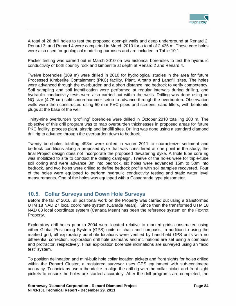
Stornoway Diamond Corporation - Renard Diamond Project Page 84 NI 43-101 Technical Report - December 29, 2011
A total of 26 drill holes to test the proposed open-pit walls and deep underground at Renard 2, Renard 3, and Renard 4 were completed in March 2010 for a total of 2,436 m. These core holes were also used for geological modelling purposes and are included in Table 10.1. Packer testing was carried out in March 2010 on two historical boreholes to test the hydraulic conductivity of both country rock and kimberlite at depth at Renard 2 and Renard 4. Twelve boreholes (109 m) were drilled in 2010 for hydrological studies in the area for future Processed Kimberlite Containment (PKC) facility, Plant, Airstrip and Landfill sites. The holes were advanced through the overburden and a short distance into bedrock to verify competency. Soil sampling and soil identification were performed at regular intervals during drilling, and hydraulic conductivity tests were also carried out within the wells. Drilling was done using an NQ-size (4.75 cm) split-spoon-hammer setup to advance through the overburden. Observation wells were then constructed using 50 mm PVC pipes and screens, sand filters, with bentonite plugs at the base of the well. Thirty-nine overburden “profiling” boreholes were drilled in October 2010 totalling 200 m. The objective of this drill program was to map overburden thicknesses in proposed areas for future PKC facility, process plant, airstrip and landfill sites. Drilling was done using a standard diamond drill rig to advance through the overburden down to bedrock. Twenty boreholes totalling 493m were drilled in winter 2011 to characterize sediment and bedrock conditions along a proposed dyke that was considered at one point in the study; the final Project design does not incorporate the proposed dewatering dyke. A triple tube core rig was mobilized to site to conduct the drilling campaign. Twelve of the holes were for triple-tube soil coring and were advance 3m into bedrock, six holes were advanced 15m to 50m into bedrock, and two holes were drilled to define bedrock profile with soil samples recovered. Four of the holes were equipped to perform hydraulic conductivity testing and static water level measurements. One of the holes was equipped with a Casagrande type piezometer.
Collar Surveys and Down Hole Surveys 10.5.Before the fall of 2010, all positional work on the Property was carried out using a transformed UTM 18 NAD 27 local coordinate system (Canada Mean). Since then the transformed UTM 18 NAD 83 local coordinate system (Canada Mean) has been the reference system on the Foxtrot Property. Exploratory drill holes prior to 2004 were located relative to marked grids constructed using either Global Positioning System (GPS) units or chain and compass. In addition to using the marked grid, all exploratory borehole locations were verified by hand-held GPS units with no differential correction. Exploration drill hole azimuths and inclinations are set using a compass and protractor, respectively. Final exploration borehole inclinations are surveyed using an “acid test” system. To position delineation and mini-bulk hole collar location pickets and front sights for holes drilled within the Renard Cluster, a registered surveyor uses GPS equipment with sub-centimetre accuracy. Technicians use a theodolite to align the drill rig with the collar picket and front sight pickets to ensure the holes are started accurately. After the drill programs are completed, the

Stornoway Diamond Corporation - Renard Diamond Project Page 85 NI 43-101 Technical Report - December 29, 2011
surveyor returns to locate the drill collar positions accurately by surveying the casings for locations and orientations. During 2003 and 2004, Corriveau J.L. and Associates Inc. of Val d’Or, Québec, surveyed all the delineation and mini-bulk (as well as several of the exploratory) borehole collars using a Leica System 500 RTK real-time, differentially corrected GPS system (DGPS) with ± one centimetre accuracy. In addition, cut-and-chained stations on the ground grids covering Renard 2, Renard 3, Renard 4, Renard 65 and Renard 8 were accurately located using the same survey equipment, and a series of control points were established on the Property. From the winter of 2005 until present, Paul Roy Surveyor of Chibougamau, Québec confirmed locations of all survey collars. The downhole track of core holes drilled at Renard 2, Renard 3, Renard 4, Renard 65, Renard 7, Renard 8, Renard 9, and Renard 10 and several exploratory holes drilled outside the Renard Cluster, were surveyed using the FlexIt borehole survey instrument to determine the azimuths and inclinations more accurately. The FlexIt instrument is an electronic downhole compass tool that measures several parameters, such as azimuth, dip, magnetic field, and dip of the magnetic field. Once the data are downloaded into a computer, a program corrects for magnetic declination and rejects readings above the average magnetic field (56,000 nanoTeslas) for the area of the Renard bodies. The readings above average generally correspond to areas of magnetic rock. In addition to the FlexIt system, a gyroscope system from Gyrosmart was used for the summer 2007 drilling campaign. This particular survey tool (IBG10), known as Imego’s digital Butterfly Gyroscope, uses a MEMS (Micro-Electro-Mechanical System) gyro sensor and allows the downhole orientation survey to be carried out inside the drill string. For the drill programs completed during 2009 and 2010, in addition to using the FlexIt tool, a DeviFlex system from Devico A.S. was used to determine borehole geometry. The DeviFlex is a non-magnetic, electronic, multishot tool that uses accelerometers and strain gauges to calculate changes in inclination and azimuth. It is not affected by magnetic fields and is used for surveying inside casings and drill strings. All the core holes drilled on the Property are surveyed for magnetic susceptibility. From 2001 to 2006, an Exploranium KT-9 hand held instrument was used to manually measure the core at select intervals. Since 2006, magnetic susceptibility readings have been taken using a continuous reading, multi-parameter probe (MPP) from Instrumentation GDD.
Drill Programs 10.6.Between 2001 and 2002, drilling in the Renard Core Area was undertaken primarily as early-stage, exploration-focused programs. From 2003, most of the drilling was used to support delineation work and advanced-stage project evaluation through the collection of mini-bulk and bulk samples for all bodies except Renard 9 and Renard 10, which were discovered in 2003. Additional target exploration drilling has been ongoing since 2001 on the larger Foxtrot Property. These drilling programs have been discussed in detail in earlier technical reports (Clements and O’Connor, 2001, 2002; Lucas et al., 2003; Lépine and O’Connor, 2004; O’Connor and Lépine, 2005, 2006). Location plans for drilling not used to support mineral resource estimation can be found in these reports. Table 10.1 summarizes the drilling on the Foxtrot Property. Drill hole collar locations and outlines of the kimberlite bodies contributing to the Mineral Resource Estimate are discussed in

Stornoway Diamond Corporation - Renard Diamond Project Page 86 NI 43-101 Technical Report - December 29, 2011
Section 14. Details of the 2009 program can be found in the May 2010 Preliminary Assessment (Lecuyer et al., 2010).
10.6.1 2010 Drilling
In 2010 two drill campaigns were completed. The winter program was undertaken between March 1 and April 10 and focused on proving kimberlite at depth on Renard 3, Renard 4 and Renard 65. It also included 26 geotechnical drill holes on Renard 2, Renard 3 and Renard 4 to characterize the rock in the area of the proposed mining pits. Eight HQ (6.35 cm) holes were drilled at Renard 2 for 540 m and nine NQ and HQ holes were completed on Renard 3 for 964 m. Eleven HQ and NQ holes were drilled on Renard 4 for a total of 2,112 m and one 531 m HQ hole was drilled on Renard 65. This campaign confirmed the presence of kimberlite below the 2009 model depth for Renard 3, 4 and 65. On Renard 4 the deepest hole terminated in kimberlite at 766 m below surface without delineating the eastern contact at this depth. On both Renard 3 and Renard 65 the winter drilling increased the size of the pipe shape at depth. The summer/fall drilling had the same objectives as the winter drilling and was completed between August 26 and September 26. One 58 m NQ geochemical hole was drilled on Renard 2. Two holes were drilled on Renard 3 (including one extension of a hole that was drilled in 2007) for a total of 610 m. One 717 m HQ hole was drilled on Renard 4 and one 685 m NQ hole was drilled on Renard 1. Two HQ holes (including one extension of a hole drilled in 2008) were completed on Renard 65 for a total of 1,149 m. Finally, four NQ condemnation holes were drilled in the area of the proposed mining infrastructure for a total of 427 m. As with the winter campaign the summer/fall drilling confirmed the presence of kimberlite at depth for Renard 1, Renard 3, Renard 4 and Renard 65. No kimberlite was found in the area of the condemnation drilling.

Stornoway Diamond Corporation - Renard Diamond Project Page 87 NI 43-101 Technical Report - December 29, 2011
11.0 SAMPLE PREPARATION, ANALYSES AND SECURITY
Laboratories 11.1.Three Dense Media Separation (DMS) process facilities have been used as primary macrodiamond extraction laboratories during the Renard exploration programs to date: an external unrelated 10 tph commercial facility at Thunder Bay, Ontario (owned and operated by Kennecott Canada Exploration Inc. and doing business as the Thunder Bay Mineral Processing Laboratory (TBMPL)); an internal 5 tph facility situated in North Vancouver, British Columbia (owned and operated by Stornoway); and, an internal 10 tph facility situated at Camp Lagopède, Québec (owned by Stornoway and SOQUEM, and operated by Stornoway on behalf of the joint venture). The TBMPL is accredited by the Standards Council of Canada to the ISO/IEC 17025 standard as a testing laboratory for specific tests. Neither of the internal DMS facilities are accredited, but have been independently audited and are subjected to ongoing QA/QC testing. One non-accredited laboratory (Microlithics Laboratories Inc., Thunder Bay, ON) was used as a secondary facility for auditing tailings from mini-bulk and bulk samples. Kimberlite concentrate generated by the TBMPL and Lagopède DMS facilities was shipped to the North Vancouver laboratory for final treatment and recovery of diamonds. During the Renard exploration programs, microdiamonds were recovered by one internal facility situated in North Vancouver, British Columbia (owned and operated by Stornoway) and four external unrelated commercial facilities: Microlithics Laboratories Inc. located in Thunder Bay, ON; Saskatchewan Research Council Geoanalytical Laboratories (SRC), Saskatoon, SK; TBMPL (owned and operated by Kennecott Canada Exploration Inc.), Thunder Bay; ON; and, SGS Lakefield Research Ltd. (Lakefield) in Lakefield, ON. Neither Stornoway’s internal facility nor Microlithics Laboratories are accredited, but have been independently audited and are subjected to ongoing QA/QC testing. Both Lakefield and SRC are accredited by the Standards Council of Canada under ISO/IEC 17025 “General Requirements for the Accreditation of Calibration and Testing Laboratories (CAN-P-4D)”. The TBMPL is accredited by the Standards Council of Canada to the ISO/IEC 17025 standard as a testing laboratory for specific tests. Microlithics, SRC and SGS Lakefield were further utilized as secondary laboratories to cross-check and verify recoveries from other microdiamond facilities.
Dense Media Separation (DMS) Facilities 11.2.Dense media separation is a standard industry process for the liberation and extraction of macrodiamonds from large volumes of sample material (commonly tens to thousands of tonnes). Rock samples are progressively crushed and the disaggregated material passed over a series of size sorting screens before being mixed with a slurry of ferrosilicon and water. A cyclone is used to split the heavy minerals, including diamonds, from the lighter waste rock. The heavy mineral concentrate is removed from the DMS plant and stored under secure conditions until the diamonds can be extracted. Waste material is recycled through the plant and recrushed to liberate finer and finer diamonds. The minimum and maximum diamond size that can be recovered by the process is determined by the plant configuration. For the Renard Project, all DMS plants targeted stones of +1 DTC screen size (essentially equivalent to a +1.18 mm square-mesh screen size).
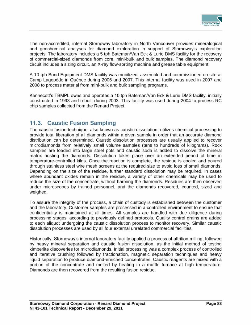
Stornoway Diamond Corporation - Renard Diamond Project Page 88 NI 43-101 Technical Report - December 29, 2011
The non-accredited, internal Stornoway laboratory in North Vancouver provides mineralogical and geochemical analyses for diamond exploration in support of Stornoway’s exploration projects. The laboratory includes a 5 tph Bateman/Van Eck & Lurie DMS facility for the recovery of commercial-sized diamonds from core, mini-bulk and bulk samples. The diamond recovery circuit includes a sizing circuit, an X-ray flow-sorting machine and grease table equipment. A 10 tph Bond Equipment DMS facility was mobilized, assembled and commissioned on site at Camp Lagopède in Québec during 2006 and 2007. This internal facility was used in 2007 and 2008 to process material from mini-bulk and bulk sampling programs. Kennecott’s TBMPL owns and operates a 10 tph Bateman/Van Eck & Lurie DMS facility, initially constructed in 1993 and rebuilt during 2003. This facility was used during 2004 to process RC chip samples collected from the Renard Project.
Caustic Fusion Sampling 11.3.The caustic fusion technique, also known as caustic dissolution, utilizes chemical processing to provide total liberation of all diamonds within a given sample in order that an accurate diamond distribution can be determined. Caustic dissolution processes are usually applied to recover microdiamonds from relatively small volume samples (tens to hundreds of kilograms). Rock samples are loaded into large steel pots and caustic soda is added to dissolve the mineral matrix hosting the diamonds. Dissolution takes place over an extended period of time in temperature-controlled kilns. Once the reaction is complete, the residue is cooled and poured through stainless steel wire mesh screens at the required size to avoid loss of small diamonds. Depending on the size of the residue, further standard dissolution may be required. In cases where abundant oxides remain in the residue, a variety of other chemicals may be used to reduce the size of the concentrate, without harming the diamonds. Residues are then observed under microscopes by trained personnel, and the diamonds recovered, counted, sized and weighed. To assure the integrity of the process, a chain of custody is established between the customer and the laboratory. Customer samples are processed in a controlled environment to ensure that confidentiality is maintained at all times. All samples are handled with due diligence during processing stages, according to previously defined protocols. Quality control grains are added to each aliquot undergoing the caustic dissolution process to monitor recovery. Similar caustic dissolution processes are used by all four external unrelated commercial facilities. Historically, Stornoway’s internal laboratory facility applied a process of attrition milling, followed by heavy mineral separation and caustic fusion dissolution, as the initial method of testing kimberlite discoveries for microdiamonds. Initial processing was a complex process of controlled and iterative crushing followed by fractionation, magnetic separation techniques and heavy liquid separation to produce diamond-enriched concentrates. Caustic reagents are mixed with a portion of the concentrate and melted by heating in a muffle furnace at high temperature. Diamonds are then recovered from the resulting fusion residue.

Stornoway Diamond Corporation - Renard Diamond Project Page 89 NI 43-101 Technical Report - December 29, 2011
Database 11.4.Data collected from the various exploration, mini-bulk, and sampling programs were collated into a SQL Server relational database. Data requests are processed through the database administrator. Access to the data in SQL Server is restricted to the database administrator only. The database is stored on the server in the North Vancouver office, with backups being performed every day. One copy of the database is removed from site on a regular basis. Processing and diamond results hard copy data are stored in fire resistant filing cabinets in the North Vancouver office as are hard copy data of the Renard core field logging. In addition, these hardcopies have been scanned as digital PDF files which are stored on the server.
Sample Security 11.5.All sample processing is undertaken by qualified operators who conduct their work in secure laboratory areas with restricted access and following strict sample handling protocols. Diamonds recovered from the caustic dissolution process are generally very small (<0.85 mm), have limited commercial value and the focus is to extract and retain all available stones. Security, while present, does not form as large a component of process as it does for the DMS work which can recover hundreds of carats of diamonds, many of which may be potentially attractive for theft. DMS operations, post-processing treatment of DMS concentrates, observing, and post-observation handling of concentrates and diamonds, from 2004 to the effective date of this report, were conducted under approved security protocols and procedures, which include but are not limited to:
Chain of Custody documentation;
Dual locking containers;
Uniquely numbered, single use, tamper resistant seals;
Monitoring and control of sample weights;
Limited access or dual access to certain laboratory premises;
Closed-circuit TV surveillance; and
External (third party) security guards.
Comparative analysis of diamond size distribution is checked against historical and external laboratory results.
Drill Core 11.6.In the case of drill core collected for microdiamond analyses (i.e. caustic dissolution) during the 2009 and 2010 drill programs, once sample intervals had been established in the field, core was extracted from the core boxes and packed into 20 l, white plastic pails lined with heavy polyethylene sample bags. Bar coded sample tags with unique identification numbers were inserted into each sample bag and the bags sealed. Pails were clearly labeled inside and out

Stornoway Diamond Corporation - Renard Diamond Project Page 90 NI 43-101 Technical Report - December 29, 2011
with the same sample number, and then sealed with tamper resistant single use lids. Individual pail weights were recorded and this information forwarded to the company’s expeditor in Chibougamau and the office in North Vancouver. The expeditor was notified once the pails left camp on a charter aircraft, met the aircraft at the landing site and transferred the sample pails to a secure location. The pails were then consigned to a commercial courier service for delivery to either the contract caustic fusion laboratory or to North Vancouver. Upon receipt of the samples the caustic fusion facility would take possession of the samples, document the number and weight of the pails and notify both the camp and the North Vancouver office. In certain cases diamond spikes were added to the core samples to assist in the sample tracking and QA/QC verification procedures. Historically, during drilling operations for mini-bulk sampling, specific security measures were instituted to minimize the potential for tampering and to maintain the integrity of the drill core from initial coring on site to delivery of the core to the North Vancouver laboratory. Once a full core tray has been reviewed by a joint venture geologist at the drill rig, the core boxes are sealed for transport by helicopter or ground transport to the core logging facility located at the Lagopède base camp, approximately 500 m west of the Renard kimberlite cluster. The core boxes are opened in the core library for detailed inspection, photographing and logging. The core library is a secure, locked facility without windows. Only authorized personnel are allowed inside. Once logging is complete, core boxes are resealed and sent by various types of charter aircraft to LG-4 or Chibougamau where a quality control officer, employed by the joint venture, receives them. Core boxes are transferred by forklift truck from the aircraft to a semi-truck trailer and organized on palettes for delivery to Vancouver. The boxes are metal-strapped in a minimum of two locations to avoid movement during transport. Locks with hardened steel shackles secure the semi-trailer when the quality control officer is not present. The on-site quality control officer, the project manager located at the remote base camp, and the North Vancouver laboratory manager possess keys for the trailer locks. Once the semi-trailer is fully loaded, it is locked a final time and numbered security seals are placed on the lock hasp. The trailer is then dispatched to North Vancouver, where it is received by the laboratory manager. All the information such as seal number, trailer and container numbers, and date of departure is transmitted to the Vancouver office. Once the shipment arrives in Vancouver, the seal is verified and the van is off-loaded by a technician who verifies the contents against the chain of custody.
Reverse Circulation (RC) Chips 11.7.Reverse Circulation sample drilling operations occur under strict security measures to minimize potential tampering and to maintain the integrity of the samples while being shipped from the drill site to the North Vancouver or commercial laboratory. A fenced area with controlled access at the Lagopède camp and/or the LG-4 site, was used for temporary storage of RC chip samples during the summer 2004 and 2006 drilling programs, prior to shipping the samples south. For the winter and fall 2007 RC drilling program, RC bags were stored in a restricted access area adjacent to the Lagopède DMS facility, before being processed on site. Joint venture geologists supervised the sample collection. During drilling, access to kimberlitic chips was limited to authorized joint venture staff and drillers. Once filled, 1.5 t sample bags or

Stornoway Diamond Corporation - Renard Diamond Project Page 91 NI 43-101 Technical Report - December 29, 2011
205 l steel drums were sealed immediately with cable ties and a security seal was applied to deter opening the bags or the drums. The bags and the barrels were loaded on pallets and transported by forklift to the camp’s restricted loading area until loaded into aircraft. During the 2004 and 2006 winter drilling program, large capacity aircraft were used to transport the material to Chibougamau or Mirage. Once at the destination, the bags were unloaded from the aircraft for storage at a secure location where only authorized personnel were permitted, before being shipped to the Thunder Bay DMS facility or the North Vancouver facilities. During the summer of 2004, float-equipped airplanes were used to carry secured 205 l barrels to Mirage, a tourist outfitter lodge near LG-4, before being shipped to the Thunder Bay DMS facility. Seal number, trailer and container numbers and date of departure were recorded on the chain of custody and were transmitted to the Vancouver office. Once the shipment was in Vancouver, the seal was verified and the van was off-loaded by a technician who verified the contents against the shipping papers and checked sample weights.
Bulk Sampling 11.8.11.8.1 Underground Bulk Samples
Access to the underground workings was restricted to ensure safety of personnel, as well as security and integrity of the samples. Only personnel involved in the underground program had access to the kimberlite, such as geologists, surveyors, equipment operators and drillers. On surface, the sample storage areas, treatment compound and DMS facility were considered as restricted areas and subject to access control, camera surveillance and security monitoring. An independent Québec-based security firm, Canaprobe, was mandated to implement site security protocols and provided bonded security officers. During bulk sample processing, only authorized personnel had access to the restricted areas. Security personnel escorted all approved visitors. All personnel involved in the operations at the DMS facility were subject to criminal record checks and random daily searches. Surveillance by the security force included use of overlapping and task specific CCTV coverage, as well as a continuous physical presence within the DMS plant. Locked dual custody provisions were in force in the vicinity of the DMS concentrate. The concentrate was discharged from the DMS into 205 l steel drums lined with a heavy polyethylene sample bag. Once sample processing was complete, or the drum was full, the sample bag was sealed with a numbered tamper-resistant security tag by both a processing representative and a security representative. Each drum was mechanically sealed, locked and secured with two additional numbered tags. Sealed concentrate drums were weighted, labelled and moved to a secure, access controlled, storage site under constant camera surveillance and chain of custody documentation. Once enough concentrate drums had been collected, they were removed from site on a charter aircraft and transported under chain of custody to Chibougamau or Mirage, where they were temporarily stored in locked containers or secure vans before being shipped to North Vancouver with a bonded trucking company. Concentrate was transported in a locked, sealed and documented tractor-trailer on a “non-stop, 24/7” continuous basis from Chibougamau or Mirage directly to North Vancouver. Concentrate reception in North Vancouver was under dual custody conditions and included monitoring by external security officers, drum/external security seal number verification, integrity inspections and weight control. Concentrate drums were then placed in a locked, access-controlled storage
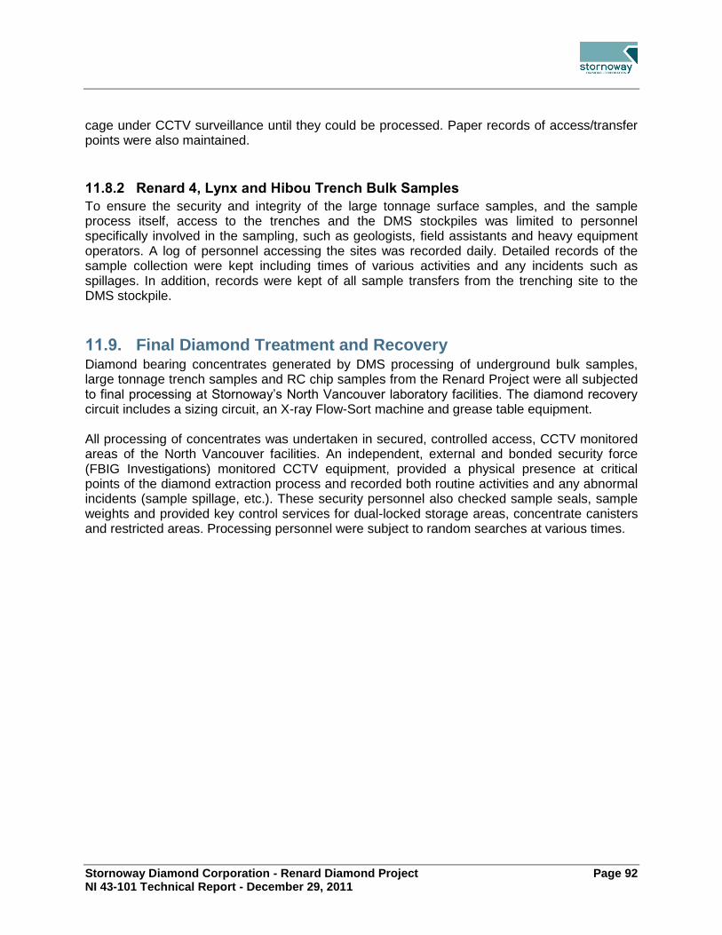
Stornoway Diamond Corporation - Renard Diamond Project Page 92 NI 43-101 Technical Report - December 29, 2011
cage under CCTV surveillance until they could be processed. Paper records of access/transfer points were also maintained.
11.8.2 Renard 4, Lynx and Hibou Trench Bulk Samples
To ensure the security and integrity of the large tonnage surface samples, and the sample process itself, access to the trenches and the DMS stockpiles was limited to personnel specifically involved in the sampling, such as geologists, field assistants and heavy equipment operators. A log of personnel accessing the sites was recorded daily. Detailed records of the sample collection were kept including times of various activities and any incidents such as spillages. In addition, records were kept of all sample transfers from the trenching site to the DMS stockpile.
Final Diamond Treatment and Recovery 11.9.Diamond bearing concentrates generated by DMS processing of underground bulk samples, large tonnage trench samples and RC chip samples from the Renard Project were all subjected to final processing at Stornoway’s North Vancouver laboratory facilities. The diamond recovery circuit includes a sizing circuit, an X-ray Flow-Sort machine and grease table equipment. All processing of concentrates was undertaken in secured, controlled access, CCTV monitored areas of the North Vancouver facilities. An independent, external and bonded security force (FBIG Investigations) monitored CCTV equipment, provided a physical presence at critical points of the diamond extraction process and recorded both routine activities and any abnormal incidents (sample spillage, etc.). These security personnel also checked sample seals, sample weights and provided key control services for dual-locked storage areas, concentrate canisters and restricted areas. Processing personnel were subject to random searches at various times.

Stornoway Diamond Corporation - Renard Diamond Project Page 93 NI 43-101 Technical Report - December 29, 2011
12.0 DATA VERIFICATION
Stornoway Quality Assurance and Quality Control Programs 12.1.The descriptions of the Stornoway QA/QC programs are taken from O’Connor and Lépine (2005; 2006) and Lecuyer et al. (2009).
12.1.1 Caustic Fusion and DMS Sampling
QA/QC testing is conducted on 5% of all samples passing through the North Vancouver caustic fusion dissolution circuit and Dense Media Separation (DMS) circuit. GeoStrat Consulting Services Inc. (GeoStrat reviewed the QA/QC procedures but did not independently verify the QA/QC procedures for the caustic fusion and DMS samples. QA/QC programs conducted by Stornoway include:
Blind spiking of samples in processing, using “known” natural and synthetic diamonds prior to processing with recovery determined at the observation stage;
Blind spiking of samples in observing, using “known” diamonds prior to observation;
Regular testing of all machines and equipment;
Calibration and verification procedures;
Routine audits of non-observable fractions and reject materials;
Use of internal standards and reference materials which are calibrated to provide traceability and reproducibility;
A record-keeping system of documentation, which retains in archives all original records and data, with all amendments clearly marked, initialled and dated for reference;
Corrective actions which are implemented immediately when any aspect of laboratory analysis, or chain of custody documentation does not conform to procedural standards;
The investigation and verification of any result which appears to be a potential statistical anomaly, to ensure laboratory results fit within the geological context; and
Use of external laboratories for check samples. Up to 5% of all samples are routinely sent for external analysis.
The caustic fusion and DMS diamond recovery facilities are governed by a series of detailed procedures that are appropriate to ensure the security and integrity of samples and the final results. All samples received in the laboratory are accompanied by a chain of custody document and with security seals that must be verified prior to processing any sample. Upon receipt, the samples are stored in a secure facility with restricted access. The diamond recovery circuits are in restricted areas and all samples, concentrates, diamonds and data are locked in safes, cabinets, drying ovens, or secure rooms when not being handled.

Stornoway Diamond Corporation - Renard Diamond Project Page 94 NI 43-101 Technical Report - December 29, 2011
GeoStrat Verification 12.2.As part of the independent expert review, David Farrow and Darrell Farrow conducted the following verification checks on the Foxtrot Property:
Site visit by David Farrow and Darrell Farrow from March 5 to March 8, 2009;
Review of the surface and underground geological and mineralization interpretations (Section 7);
Review of the historic and current exploration programs (Sections 6 and 9);
Deposit model (Section 8);
Review of data that are supporting mineral resource models (Sections 9, 10, and 11). The review covered drill core inspection, review of core logging, sampling and assay protocols and methods, and review of sample security measures and sample storage;
Review of QA/QC data protocols and methods, data integrity and validation of RC, drill core and underground data (Sections 11 and 12), and
Review of diamond valuation methodologies.
GeoStrat has visited the Project site and the North Vancouver offices in order to audit procedures at Stornoway. Independent samples were not collected and treated by GeoStrat since this is not practical for diamond sampling. The audit process requires matching of raw data from field copies for the various data collection areas to final copies of data to be used in public reporting and resource estimation. GeoStrat has further reviewed documentation of procedures and verified that activities in the field conform to Stornoway’s published internal procedures for those activities. GeoStrat is of the opinion that Stornoway’s published and practiced procedures for collection of data in the field and transposition of these data into data ‘products’ to support resource evaluation work and initial costing exercises meet industry best practice guidelines.
12.2.1 Special Considerations for Diamond Resource Determination
Unlike commodities such as gold or base metals, diamonds do not have a standard value per unit weight that can be used to calculate value of a deposit. A one carat diamond can be worth from less than one dollar to tens of thousands of dollars, depending on the shape, colour and quality. A parcel of diamonds must be individually examined to establish an average value. Diamond values also change with the mix of diamonds over time, however, as a whole, diamond values have tended to increase with time. As this can be a somewhat subjective exercise, multiple valuations from different professional diamond valuers, or diamantaires, are necessary, and are usually averaged to give an estimate of the probable true price of the goods in question. Diamond price estimates can differ between valuers by as much as ± 20%, especially on smaller parcels of diamonds. These differences are simply due to the fact that different diamantaires will perceive the value of a stone or parcel of stones differently. Their price guidelines will differ somewhat as well.

Stornoway Diamond Corporation - Renard Diamond Project Page 95 NI 43-101 Technical Report - December 29, 2011
In a valuation exercise, it is necessary to involve a number of diamantaires to obtain a range of valuations that can be averaged to get an accurate price estimate and to use these data to model an average price. Often, in early stage evaluations of diamond projects, diamond price modelling is undertaken. In price modelling, the small sample size is compensated for by estimation of what the diamond population in a larger sample would be. By doing this, the valuer attempts to predict the likelihood of finding larger stones and what their effect on the overall value of the parcel would be and, as such, estimate more closely what the run-of-mine (ROM) value would be. Modelling involves study of the diamond parcel on hand, including size distributions and valuations, to statistically estimate the upper and lower limits of a production parcel at certain confidence levels based upon the small parcel on hand. To accomplish this, Stornoway contracted WWW Diamond Consultants International (WWW) of London to obtain valuations and perform price modelling. WWW are recognized international leaders in this field. Small parcels of diamonds are difficult and time consuming to value, so individual sample goods are generally combined on the basis of geology or some other parameter. Valuation parcels are generally sieved into DTC sieve classes (+1, +3, +5, +7, +9, +11) and grainer and carater categories. A cumulative 8,315.58 carat diamond parcel acquired by bulk sampling underground, trench sampling and RC drilling completed by Stornoway between 2003 and 2007 was used for value modelling.
13.0 MINERAL PROCESSING AND METALLURGICAL TESTING
Introduction 13.1.Dense media separation (DMS) is a standard industry process for the liberation and extraction of commercial sized macrodiamonds from large volumes of core, mini-bulk and bulk sample material. Rock samples are progressively crushed and the disaggregated material passed over a series of size-sorting screens before being mixed with a slurry of ferrosilicon and water. A cyclone is used to separate the heavy minerals, including diamonds, from the lighter waste rock. The heavy mineral concentrate is removed from the DMS plant and the diamonds are extracted. Waste material is recycled through the plant and recrushed to liberate finer and finer diamonds. The minimum and maximum diamond size that can be recovered by the process is determined by the plant configuration. For the Renard Project, all DMS plants targeted stones of +1 DTC screen size (essentially equivalent to a +1.18 mm square-mesh screen size) or above, although smaller stones have been recovered. Three DMS process facilities have been used as primary macrodiamond extraction laboratories during the Renard exploration programs to date: an internal 10 tph facility situated at Camp Lagopède, Québec (owned by Stornoway Diamond Corporation (Stornoway) and SOQUEM Inc. (Soquem), and operated by Stornoway on behalf of the joint venture); an external unrelated 10 tph commercial facility at Thunder Bay, Ontario (owned and operated by Kennecott Canada Exploration Inc. and doing business as the Thunder Bay Mineral Processing Laboratory (TBMPL); and an internal 5 tph facility situated in North Vancouver, British Columbia (owned and operated by Stornoway). By far the largest proportion of DMS processing has been through the Lagopède plant, as shown by facility and sample type in Table 13.1. Table 13.2 shows the sample breakdown for the individual Renard kimberlite bodies comprising the current resource calculations.

Stornoway Diamond Corporation - Renard Diamond Project Page 96 NI 43-101 Technical Report - December 29, 2011
Table 13.1: DMS Facilities – Sample Processing Breakdown
Sample Type Lagopède TBMPL North Vancouver
# Samples Weight (t) # Samples Weight (t) # Samples Weight (t)
RC 33 173.5 57 617.3 33 111.7
Surface 15 3457.4 0 0 27 109.0
Core 0 0 0 0 200 174.5
Underground 28 4562.5 0 0 0 0
Totals 76 8193.4 57 617.3 260 395.2
Table 13.2: DMS Facilities – Allocation of Resource Sample Processing
Resource Body
DMS Plant
Total Weight Processed (tonnes)
Lagopède TBMPL North Vancouver
Renard 2 2535.6 171.2 34.6
Renard 3 2173.1 157.0 18.6
Renard 4 2104.2 141.8 103.0
Renard 65 266.0 147.2 38.4
Renard 9 27.3 0 82.5
Lynx 494.3 0 48.9
Hibou 564.9 0 30.1
Totals 8165.4 617.2 356.1
The basic flow sheet used for each of the three mineral processing facilities is described in the following subsections, as well as an outline of the QA/QC procedures.

Stornoway Diamond Corporation - Renard Diamond Project Page 97 NI 43-101 Technical Report - December 29, 2011
DMS Processing - Lagopède 13.2.A 10-tonne-per-hour Bond Equipment DMS facility was mobilized, assembled and commissioned on site at Camp Lagopède in Québec during 2006 and 2007. Stornoway operated this facility in 2007 and 2008 to process material from mini-bulk and bulk sampling programs. Trained DMS process operators supervised each shift in a secure building. Sample processing followed procedures similar to those of the Thunder Bay and North Vancouver facilities, with some exceptions due to the nature of remote field operations, as noted below. After excavation, kimberlite samples were stockpiled outside the facility in a secure compound with restricted access. Individual samples were prepared through a primary jaw crusher, and 50.0 mm crushed product fed directly into the DMS facility where a scrubber trommel unit removes the +20.0 mm oversize. The +20.0 mm oversize material was reduced using a secondary cone crusher set at 10.0 mm. Coarse rejects were recrushed to -6.0 mm and re-circulated through the facility. The first seven subsamples of the 2007 bulk sample program used a 1.2 mm by 13.0 mm slotted screen. Subsequent samples employed a 1.0 mm by 12.0 mm slotted screen to increase the recovery of smaller diamonds. Contract security services were provided on site by an independent third party (Groupe Canaprobe of Montréal, Québec). DMS concentrates generated by the Lagopède facility were sealed in drums and dispatched in a locked container under chain of custody protocols to Stornoway’s internal laboratory in North Vancouver for final treatment and recovery of diamonds. The laboratory owns and operates integrated diamond recovery equipment including a sizing circuit, X-ray flow-sort machine and grease table. Upon arrival at the North Vancouver diamond recovery facility, concentrates are screened into four size fractions, passed through an X-ray sorter twice, and the tailings diverted to a grease table circuit to generate a final diamond concentrate. Diamond-enriched concentrates are stored in sealed lock boxes within high security cages before being transferred to the observation laboratory for final diamond recovery and reporting. A team of trained mineral observers and mineralogists undertakes final diamond recovery using a combination of hand-sorting and binocular microscopy techniques. All diamonds recovered are routinely verified, described, weighed, photographed and recorded by trained mineralogists. Results are reported as diamonds retained on a +1 DTC sieve, or as stones greater than 1.18 mm using Tyler square mesh sieve classes when required. All diamond recovery is carried out with dual custody handling provisions under video surveillance in restricted areas. An independent external security team monitors and records all operations, transfers and seal control. FBIG Investigations (Vancouver, BC) has provided these contract services since 2004. Neither the internal DMS facility nor the diamond recovery circuit are accredited, but both have been independently audited and are subjected to ongoing QA/QC testing.
DMS Processing – Thunder Bay Mineral Processing Laboratory 13.3.Kennecott’s TBMPL owns and operates a 10-tonne-per-hour Bateman/Van Eck & Lurie DMS facility, initially constructed in 1993 and rebuilt in Thunder Bay during 2002 and 2003. This facility was used on two occasions in 2004 to process RC chip samples collected from the Renard Project. Operators from Stornoway’s North Vancouver facility supervised contract DMS processing in Thunder Bay to verify the quality and continuity of work being performed. The
Stornoway Diamond Corporation - Renard Diamond Project Page 98 NI 43-101 Technical Report - December 29, 2011
TBMPL is accredited by the Standards Council of Canada to the ISO/IEC 17025 standard as a testing laboratory for specific tests. RC chip samples were sent to the facility in sealed pails, drums, or bulk bags, each with an individual sample number and security seal. Security seals were verified as being intact upon arrival at the laboratory, recorded in a chain of custody document and isolated in a secure storage area with controlled access overseen by an external independent security service (Apex Security, Thunder Bay). The same security team also monitored DMS processing and maintained video surveillance in restricted areas. Since the kimberlite material was already broken into chips from the RC drilling process, it was directly fed to the DMS scrubber unit, to remove the +16.0 mm oversize fraction which was sent to a secondary rolls crusher set at 8.0 mm. Kimberlite was processed through the facility then the tails screened at 6.0 mm. Tails greater than 6.0 mm were recrushed in a roll crusher set at 3.8 mm and repassed through the plant. Finer tails were discarded. A 0.85 mm by 14.0 mm slotted product screen was used within the Thunder Bay DMS facility. DMS concentrates were dried, then screened into six size fractions before being sent to the North Vancouver laboratory in secure shipments for further processing by heavy liquid and magnetic separation techniques. Final diamond recovery, classification and reporting were also carried out in North Vancouver under secure, independently monitored conditions (FGIB Investigations, Vancouver, BC).
DMS Processing – North Vancouver Facility 13.4.Stornoway’s internal laboratory in North Vancouver provides mineralogical and geochemical analyses for diamond exploration in support of Stornoway’s exploration programs. The laboratory includes a 5-tonne-per-hour Bateman/Van Eck & Lurie DMS facility and a diamond recovery circuit. Kimberlite samples are received at the laboratory as small diameter drill core in sealed core boxes, reverse circulation drill chips in sealed pails, bags or drums, or as surface material from outcrop or boulders packed in drums or bulk bags. Each box, pail, bag or drum is given an individual sample number and sealed in the field prior to shipment. Bags and drums are identified with security seals that are verified as being intact upon arrival at the laboratory in a locked and sealed shipment. Once the chain of custody documents, sample numbers, and security seals have been checked and verified, the sample is isolated in a secure storage area with restricted access. Trained operators conduct DMS processing in a secure portion of the laboratory. Samples are initially reduced through a primary jaw crusher at a nominal gap of 20.0 mm to 25.0 mm. This material is then passed through a combination of jaw and roll crushing at a nominal gap of 10.0 mm to 14.0 mm. The crushed product is fed into the five-tonne-per-hour DMS facility where a scrubber trommel unit removes the +14.0 mm oversize for recrushing. After primary feeding and sizing, all sample material is processed through the cyclone. DMS floats are screened at 4.0 mm with the undersize going to tails, and the oversize to iterative recrushing and repassing at 4.0 mm and 2.0 mm to minimize the potential for diamond breakage. On early samples, a 1.0 mm by 12.0 mm slotted screen was employed within the DMS facility. In 2006, this was changed to a 0.85 mm by 14.0 mm slotted screen to better

Stornoway Diamond Corporation - Renard Diamond Project Page 99 NI 43-101 Technical Report - December 29, 2011
recover small diamonds, ensure a bottom diamond cut-point of 1.18 mm using a Tyler square mesh screen, and produce a minimum stone size smaller than that generally retained on a +1 DTC sieve. Resultant DMS concentrates are screened into four or six size fractions, passed through an X-ray sorter twice, and the final tailings diverted to a grease table circuit for final recovery. Heavy liquid and magnetic separation recovery methods were employed on samples prior to 2006. Diamond-enriched concentrates are stored in sealed lock boxes within high security cages before being transferred to the observation laboratory for final diamond recovery and reporting. Final diamond recovery, classification and reporting were also carried out in North Vancouver under secure, independently monitored conditions (FBIG Investigations, Vancouver, BC). Neither the internal DMS facility nor the diamond recovery circuit are accredited, but both have been independently audited and are subjected to ongoing QA/QC testing.
QA/QC 13.5.Quality control testing was routinely conducted on drill core, RC chip, surface and underground samples processed through the three DMS facilities. Tailings and various processing residues are also subject to audit. QA/QC measures include but are not limited to:
Adherence to established/documented processing and handling protocols;
Systematic density bead tracer testing prior to operating plant to ensure efficiency and diamond recovery;
Addition of luminescent density tracers prior to DMS to monitor processing and X-ray sorter efficiency. Recovery is measured after X-ray sorter recovery;
Addition of identifiable natural diamond spikes prior to any DMS processing; recovery is measured at the diamond sorting stage;
Addition of natural diamonds prior to observation to determine the efficiency of diamond sorting and for security control purposes;
Audit of representative coarse DMS tailings from select kimberlite subsamples;
Re-crush of DMS tailings and concentrate tailings to monitor processing efficiency, X-ray/grease recovery, and diamond liberation;
Regular DMS feed size analysis;
Testing of processing circuit clean-out residues;
Audits of processing rejects using secondary laboratories and DMS facilities;
Monitoring of diamond recovery statistics, including size frequency analyses;
Independent third party audit processes (spiking, process review, etc.); and
Review and audit of DMS and diamond data, operating procedures and QA/QC programs.

Stornoway Diamond Corporation - Renard Diamond Project Page 100 NI 43-101 Technical Report - December 29, 2011
Metallurgical Testing 13.6.13.6.1 Mini Bulk Sample Processing
During advanced-stage evaluation of the Project, mini-bulk samples from drill core and RC chips (Renard 2, Renard 3 and Renard 4) were processed using small scale diamond processing plants located in Stornoway’s facilities at North Vancouver and on site at Camp Lagopede in Québec. Some useful dense medium separation (DMS) concentrate yield data were generated. The information is based on dry concentrate weight and dry plant feed weight expressed as a percentage and summarized in Tables 13.3 and 13.4.
Table 13.3: DMS Yield Data – North Vancouver Plants
1 tph Plant DMS Yield 5 tph Plant DMS Yield
Max % Ave % Min % Max % Ave % Min %
Renard 2 3.07 1.59 0.22 1.63 0.61 0.12
Renard 3 3.46 2.38 1.47 2.14 0.72 0.25
Renard 4 5.78 2.3 0.46 1.06 0.23 0.05
Table 13.4: DMS Yield Data – Lagopède Plant
10 tph Plant DMS Yield
Max % Ave % Min %
Renard 2 0.2 0.13 0.06
Renard 3 0.67 0.34 0.04
Renard 4 0.24 0.14 0.08
The 1 tph plant was operated to recover diamonds greater than 0.5 mm and DMS rejects were recycled and re-crushed to liberate additional diamonds and produce final plant rejects of less than 2 mm. Compared to a commercial plant where recovery of diamonds greater than 1 mm is usually targeted and final plant rejects are crushed to less than 6 mm, or in some cases higher, the DMS yields generated in the 1 tph plant are unrealistically high for commercial plant design. The 5 tph plant was operated to recover diamonds greater than 1 mm and to produce final plant rejects less than 4 mm. Considering that the commercial plant will employ a high pressure grinding roll (HPGR) unit, which is proven to liberate diamonds and hence heavy minerals better than conventional cone crushing, it is reasonable to assume DMS yields achieved in the 5 tph plant will equate to the expected higher yields with the inclusion of a HPGR. The 10 tph plant was operated with commercial plant settings; recovery of diamonds greater than 1 mm and production of final plant rejects less than 6 mm. However, because liberation was achieved with conventional cone crushing the DMS yields will be understated if these data are applied to a circuit with a HPGR.

Stornoway Diamond Corporation - Renard Diamond Project Page 101 NI 43-101 Technical Report - December 29, 2011
Consideration of the DMS yield data generated produced plant design data presented in Table 13.5.
Table 13.5: Design SMA Yields
Max % Ave % Min %
Design
DMS Yield 2.14 1.63 1.06
AMEC considers the above design data to be conservative, leading to a moderately sized, easy to operate, recovery plant.
13.6.2 Bulk Sample Processing - 2007
Bulk samples from Renard 2 (2,449 t), Renard 3 (2,114 t) and Renard 4 (1,659 t) were processed on site at Camp Lagopède in Québec during 2007. DMS concentrate was shipped off-site to Stornoway’s recovery plant in North Vancouver. The recovered diamonds were used for diamond price estimation and grade determinations through the analysis of Size Frequency Distribution models of the Renard diamond population. The data listed below was collected during this period to support future process design.
Plant feed particle size distribution;
DMS concentrate yield;
Diamond recovery;
Diamond size frequency distributions;
Granulometry (rejects and DMS concentrate);
Plant mass balance and operating data; and
X-ray sorter concentrate yields.
Data from the bulk sample processing indicated the following:
The production of fines (-1 mm), a predictor of ore hardness, ranged from hardest to softest; Renard 3 at 26% Renard 2 at 31% and Renard 4 at 39%;
The kimberlites have a low DMS yield using conventional cone crushing for liberation;
Approximately 95% of the diamonds by weight were recovered after two stages of x-ray sorting. The remainder were recovered using a grease table;
Grease scavenging of x-ray rejects will be worthwhile in a commercial plant; and
Renard 2 exhibits potential to host larger diamonds than the standard commercial plant top size cut-off of 25 mm.

Stornoway Diamond Corporation - Renard Diamond Project Page 102 NI 43-101 Technical Report - December 29, 2011
13.6.3 Additional Testwork Completed to Support Process Design
Testwork as shown in Table 13.6 was completed to support process design.
Table 13.6: Summary of Testing Completed during Feasibility Study to Support Process Design
Tests Undertaken / Data Generated Test Location
HPGR bench scale tests to product fineness.
Results were modeled to predict full scale
performance
SGS, Ontario
HPGR pilot scale tests to determine product
fineness, influence of moisture in feed and
expected operating gap
BC Mining, Vancouver
Scrubber tests to determine resistance to
abrasion breakage
SGS, Ontario
Grindability tests to characterize ore
hardness
SGS, Ontario
Settling tests to permit thickener sizing,
select suitable flocculant and estimate
flocculant consumption
Outotec, Ontario
Filtration tests to determine dewatering
characteristics of fine kimberlite particles
Outotec, Ontario
Centrifuge tests to determine dewatering
characteristics of fine kimberlite particles
Decanter, Tennessee
Wet x-ray and magnetic separation tests
using DMS concentrate
Deb Tech, South Africa
Testwork findings were:
Renard 2 kimberlites exhibit similar impact breakage as country rock breccia containing significant granite xenoliths. The crusher work index for these samples indicates moderately hard ore.
Renard 2 kimberlites and country rock breccia are resistant to comminution by abrasion as indicated by ta values of 0.37 to 0.55, where ta is the measure of resistance to abrasion breakage. This indicates that a scrubber or a mill could be utilized for washing rather than comminution.
Laboratory scrubbing results indicate that comminution attributed to scrubbing would generate limited additional fines; less than 1% and 5.5% for Renard 2 and Renard 3 kimberlites respectively.
BC Mining generated process design data for a HPGR unit (750 mm diameter x 220 mm wide) in a tertiary crushing and recrush mode with a full feed size distribution. In the commercial plant design the required product size for treating a mixture of fresh feed (-50 mm, 135 tph) and DMS rejects (-30 +6 mm, 100 t/h) will be achieved with a specific pressing force of 2.5 N/mm2 and with a net specific energy consumption of about 2

Stornoway Diamond Corporation - Renard Diamond Project Page 103 NI 43-101 Technical Report - December 29, 2011
kWh/t. For these operating conditions a large operating gap of 34 mm is predicted thus protecting against possible diamond damage or breakage. The HPGR product flake was found to be soft and easily broken.
Outotec generated settling test and scale-up data for kimberlite slimes (-0.25 mm) thickening. Samples from Renard 2 settled easily requiring low flocculant dosage rates. In the commercial plant design, utilizing a high rate thickener, overflow clarities of 100 ppm will be achieved with a flocculant dosage of 30 g/t or slightly higher and a high density underflow of 45% w/w solids will easily be achieved and maintained.
Outotec performed filtration evaluation tests using -0.25 mm processed kimberlite. The material proved difficult to filter such that filtration of fine processed kimberlite for the purpose of dry stacking is unlikely to be successful.
Decanter Machine Inc performed pilot scale testing to determine the dewatering capabilities of an 18 x 60 solid bowl centrifuge with -1 mm processed kimberlite as feed. The tests proved that this material can be successfully dewatered for the purpose of dry stacking thus eliminating the traditional processed kimberlite containment dam with a central water pond.
HPGR product generated from Renard 2 samples was processed in Stornoway’s 5 t/h plant to produce concentrate. This material was tested in a dual wavelength x-ray machine to determine probable yields that could be obtained under production conditions. The tests demonstrated that satisfactory yields are possible with the dual wavelength feature. AMEC recommends further yield optimization work in the next phase of the Project.
Although no formal wet magnetic separator tests were performed, preliminary test runs completed by Deb Tech provided anticipated mass reductions. Wet magnetic separators may be used in the recovery plant design to provide DMS concentrate mass reductions. AMEC believes that employing x-ray sorters for bulk mass reductions instead of the combination of magnetic separators and x-ray sorters will provide greater benefit to the Project from a reduction in building height and cost.
Basis for Recovery Estimates 13.7.DMS rejects (-6 +1 mm) were collected after the treatment of sub-samples from Renard 2, 3 and 4 and reprocessed in a small scale DMS plant and in the recovery plant at Stornoway’s North Vancouver facility. From this audit exercise the lowest recovery efficiency of liberated diamonds in the Lagopede bulk sample plant was estimated to be 97.5% by carat. Further plant efficiency audits were completed by adding 30 identifiable natural diamonds to the bulk sample plant feed and in a separate audit, 20 identifiable natural diamonds were added. In the first audit, 29 out of 30 diamonds were recovered giving a recovery efficiency of 96.7% by stone and 98.2% by carat. In the second audit 100% recovery was achieved. Also in accordance with established QA/QC procedures 10 diamond simulants were added to each sample. A total of 149 simulants from 150 simulants introduced into 15 Renard 2 samples were recovered for an indicated recovery efficiency of 99.3%. All 120 simulants in 12 Renard 3 samples and 70 simulants in 7 Renard 4 samples were recovered for an indicated recovery of 100% in both cases.

Stornoway Diamond Corporation - Renard Diamond Project Page 104 NI 43-101 Technical Report - December 29, 2011
The recovery efficiency for the commercial plant is estimated to be not less than 96% by carat (97% for DMS and 99% for recovery).
Metallurgical Variability 13.8.Renard 2 will account for 83% of diamond production, Renard 3, 8% and Renard 4, 9%. All major geological units from each deposit were processed during the bulk sampling campaign at Lagopede. Also the major geological units from Renard 2, the dominant kimberlite source, were tested as described in section 13.1 above.
Comments 13.9.AMEC believes that sufficient and appropriate test work has been completed to support the feasibility study process design.

Stornoway Diamond Corporation - Renard Diamond Project Page 105 NI 43-101 Technical Report - December 29, 2011
14.0 MINERAL RESOURCE ESTIMATES
Introduction 14.1.This section documents the process by which the updated Mineral Resource Estimate for the Renard 2, Renard 3, Renard 4, Renard 65 and Renard 9 kimberlites and the Lynx and Hibou Dykes within the Renard Core Area (Figure 7.3) was established The 2010 Renard Mineral Resource Estimate Update was prepared by an independent Qualified Person, David Farrow, P.Geo., of GeoStrat. The Mineral Resource Estimate comprises the integration of kimberlite volumes, bulk density, petrology and diamond content data obtained from 88,585 m of diamond drilling, 6,151 m of reverse circulation (RC) drilling, 16.4 t of samples submitted for microdiamond analysis, 600.8 cts of diamonds (6,457 stones) recovered from RC drilling and 8,611.6 cts of diamonds (84,381 stones) recovered from surface trenching and underground bulk sampling. The methodology of the Mineral Resource Estimate has been reviewed by Darrell Farrow of GeoStrat and Dr Paddy Lawless of Dr Paddy Lawless and Associates CC. The diamond sampling database is summarized in Table 9.3 and comprises data derived from RC chip samples, core samples, trench samples and underground bulk samples. Large tonnage (trench and underground) samples were used to establish diamond grade frequency curves and average stone size for each body. RC samples, and trench samples in the case of Renard 4, Renard 65, Lynx and Hibou, were used to estimate the in situ grades of the bodies.

Stornoway Diamond Corporation - Renard Diamond Project Page 106 NI 43-101 Technical Report - December 29, 2011
Previous Work 14.2.A previous Mineral Resource Estimate was produced by Golder in 2009. The results were detailed in the previous Preliminary Assessment (Lecuyer et al, 2010) and are summarized in Table 14.1.
Table 14.1: Historical Mineral Resource as of December 2009
Mineralization
Category Renard 2 Renard 3 Renard 4 Renard 9 Lynx Hibou Total
Indicated
Tonnage 17,475,000 1,705,000 7,315,000 0 0 0 26,495,000
Total Carats 17,957,000 1,806,000 3,199,000 0 0 0 22,962,000
Average cpht 103 106 44 0 0 0 87
Average Dilution % 37 36 56 0 0 0 na
Inferred
Tonnage 5,365,000 154,000 4,572,000 5,747,000 1,798,000 178,000 17,814,000
Total Carats 6,415,000 189,000 1,874,000 2,634,000 1,924,000 256,000 13,292,000
Average cpht 120 122 41 46 107 144 75
Average Dilution % 29 37 55 66 na na na
Geological Models 14.3.Geological solid models were created by Stornoway for each of the Renard bodies included in this study: Renard 2; Renard 3; Renard 4; Renard 9; Renard 65; Lynx and Hibou. The geological models are discussed in the following sections.
Sampling Analysis 14.4.Diamond sampling of the Renard Project kimberlites includes core sampling, RC chip sampling, small tonnage trench sampling, and bulk sampling from both surface trenches and the underground exploration workings. These data have been collected, compiled and analyzed by a combination of methodologies in order to cater to the spatial distribution of sampling and the amount of information available for each kimberlite domain in each body. The evaluation process comprised the following steps:

Stornoway Diamond Corporation - Renard Diamond Project Page 107 NI 43-101 Technical Report - December 29, 2011
Analyse the macrodiamond populations to ensure they are robust for mineral resource valuation;
Develop the relationship between macrodiamond and microdiamond populations;
Establish that the microdiamond population is stable with depth;
Diamond size frequency analysis to establish undiluted grades for different lithofacies by:
o using macrodiamonds and/or microdiamonds; and
o establishing individual population grades for mixed samples.
Determine a factor to account for the presence of highly discontinuous, unmodellable units (Kimb2c, Kimb3c, Kimb4c and Kimb65);
Establish distributions for the dilution in the various bodies and lithotypes;
Bulk density analysis:
o establish bulk density per lithotype; and
Demonstrate that bulk density is constant with depth and dilution;
Geostatistical analysis and estimation of the dilution per rock type, per kimberlite;
Integration of calculated grade and density values with estimated dilution; and
Summarizing of data per lithofacies per kimberlite.
14.4.1 Macrodiamond Sample Analysis
Table 14.2 summarizes diamond recoveries from bodies that were used for size frequency analysis and estimation of average stone size.
Table 14.2: Recovery Data Used in Diamond Size Frequency Analysis
Kimberlite Weight (t) Total Stones
(+3 DTC) Carat Wt (+3 DTC) Sieve
Renard 2 UG 2,448.8 13,246 1590.58 DTC (+3)
Renard 3 UG 2,113.7 24,407 2753.995 DTC (+3)
Renard 4 Trench 2104.2 25,480 2688.71 DTC (+3)
Renard 65 Trench 266.0 450 63.625 DTC (+3)
Lynx Trench 494.3 5,271 515.32 DTC (+3)
Hibou Trench 543.9 8,401 781.49 DTC (+3)
These data and results for size frequency and carats per stone are considered representative of each body for the purposes of resource estimation.

Stornoway Diamond Corporation - Renard Diamond Project Page 108 NI 43-101 Technical Report - December 29, 2011
14.4.2 Microdiamond Sample Analysis
The relationship between microdiamonds and macrodiamonds can be used to establish diamond content for a kimberlite (Chapman and Boxer, 2004). Once established, that relationship can be applied to microdiamond sampling for grade determination. Representative samples weighing approximately 200 kg were collected from each underground bulk sample round and placed in sealed 205 l drums for storage. Archived material from specific underground rounds, representative of specific kimberlite facies, were submitted for standard caustic fusion microdiamond recovery. Dilution estimations were made for each caustic sample and were complemented by measured line scan data for each underground round. Dilution estimates were combined with microdiamond and macrodiamond results to determine undiluted stones per 10 kg, undiluted stones greater than 0.6 mm per 10 kg, undiluted total stones and a model grade Table 14.3. The model grade was adjusted to reflect non-recovery of small stones due to DMS plant inefficiencies (i.e. the adjusted model grade is lower than the unadjusted model grade).

Stornoway Diamond Corporation - Renard Diamond Project Page 109 NI 43-101 Technical Report - December 29, 2011
Table 14.3: Macrodiamond and Microdiamond Samples Used to Determine the Micro/Macro Relationship in Renard 2 and Renard 3
Kimb2
a
Kimb2
b
Kimb2
c
Kimb3
d/g
Kimb3
f
Kimb3
h
Kimb4
a
Kimb4
b
Kimb4
c
Kimb4
d
Kimb6
5a
Kimb
65b
Kimb
65c
Kimb6
5d
Microdiamond Sample
wt (kg) 207.93 486.86 579.65 419.55 222.64 102.1 869.43 276.61 245.3 44.65 599.34
445.6
2
256.0
5 607.44
Microdiamond Dilution % 50 32 11.4 14 24.7 2.9 63.1 34.4 2.9 49.63 56.7 19.4 5.0 34.4
Microdiamond Total
Stones 107 503 566 249 80 156 194 160 296 14 55 50 105 143
Undiluted Stones per
10kg 10.29 15.1 11.02 6.9 4.77 15.7 6.05 8.82 12.42 6.23 2.12 1.39 4.32 3.6
Undiluted Stones
>0.6mm per 10kg 0.58 1.14 0.99 0.582 0.12 1.31 0.5 0.99 1.0 1.78 0.19 0.22 0.37 0.35
Macrodiamond Sample
wt (t) 140.42 515.7 - 384.16 317.9 143.38 158.55 158.55 600.21 1504 185.64 198.6 - 165.03
Macrodiamond Dilution
% 35 16 - 14 25 2.9 51 37 2.0 60 49.4 18.5 - 44.37
Macrodiamond Total
Carats 58.17 646.69 - 559.14 278.62 274.81 61.48 61.48
1049.7
8.0 1672.11 45.63 40.33 - 36.23
Macrodiamond Total
Stones 512 5646 - 5207 2197 2931 927 927 10697 16376 639 360 - 544
Model Grade Adjusted
(cpht) 83 181 261 168 119 214 81 67 186 250 41 47 85 57

Stornoway Diamond Corporation - Renard Diamond Project Page 110 NI 43-101 Technical Report – December 29, 2011
To demonstrate continuity of mineralization and stability of the diamond population with depth in the Renard 2 body, sampling was undertaken on 50 m levels (horizontal slices) from beneath the previous RC and underground sampling to the base of the body at ~700 m (-200 masl) below the land surface. From each 50 m level, approximately 200 kg of Kimb2a and Kimb2b was collected from the 2009 drill core and treated for microdiamond recovery. A total of 2,046.93 kg of unit Kimb2a and 1,889.20 kg of unit Kimb2b were analyzed by standard caustic fusion processing. The results for Kimb2a and Kimb2b are presented in Figure 14.1 and Figure 14.2 respectively, as stones per hundred tonnes per unit interval plots which demonstrate that grades remain consistent with depth.
Figure 14.1: Kimb2a Microdiamond Sampling

Stornoway Diamond Corporation - Renard Diamond Project Page 111 NI 43-101 Technical Report – December 29, 2011
Figure 14.2: Kimb2b Microdiamond Sampling

Stornoway Diamond Corporation - Renard Diamond Project Page 112 NI 43-101 Technical Report – December 29, 2011
14.4.3 Macro Diamond Size Frequency Modelling
Diamond size frequency modelling was undertaken for all remaining kimberlite lithologies to determine undiluted grades for all units (Table 14.4). This was carried out primarily using the macrodiamond samples and fitting the curves to remain parallel to the microdiamond curves established for each pipe.
Table 14.4: Summary of Macrodiamond Data Modelling
Kimb3i Kimb9a Kimb9b
Macrodiamond Sample wt (t) 28.5 27.6 na
Macrodiamond Dilution % 42 59 na
Macrodiamond Total Carats 9.39 20.23 na
Macrodiamond Total Stones 77 150 na
Model Grade (cpht) 45 136 136
14.4.4 Mixed Sample Deconvolution
Deconvolution is the process of calculating individual lithofacies grades from mixed samples. Representative microdiamond and macrodiamond data for essentially pure Kimb3b and Kimb3c units were not available for grade modeling. Undiluted grades have been estimated through a back calculation methodology. Based on volume calculations from underground survey and mapping data, the proportion of undiluted Kimb3h, Kimb3d/g and Kimb3c have been calculated for underground rounds 3107, 3006, and 3008. The proportional contribution of total carats attributable to unit Kimb3d/g and Kimb3h was calculated based on pure grade calculations (see Table 14.3). This carat contribution was removed from the overall recovered carat total for each bulk sample round and the remainder attributed to the Kimb3c unit. The resulting weighted average grade for the Kimb3c unit is 230 cpht (Table 14.5). A similar exercise was conducted for the Kimb3b unit and involved bulk sample rounds 3104 and 3105 which are mixtures of Kimb3h, Kimb3d/g and Kimb3b. The undiluted proportion of carats was calculated for Kimb3h, and Kimb3d and removed from the total carats recovered from the bulk sample rounds. The remaining carats were assigned to unit Kimb3b and the weighted average grade for Kimb3b is 101 cpht (Table 14.5).

Stornoway Diamond Corporation - Renard Diamond Project Page 113 NI 43-101 Technical Report – December 29, 2011
Table 14.5: Calculated Macrodiamond Grades
Kimb3b* Kimb3c*
Macrodiamond Sample wt (t) 348.3 521.7
Macrodiamond Dilution % 50.61 11.72
Macrodiamond Total Carats 244.98 938.19
Proportional Carat Contribution (3h, 3dg) 136.06 476.57
Proportional Weight (Kg) 108.2 201.1
Proportional Carat Contribution 108.92 461.62
Model Grade (cpht) 101 230
* Grades back calculated by stripping out contributions from Kimb3h and Kimb3d/g
14.4.5 Intrusions of Hypabyssal Coherent Kimberlite
Individual Kimb2c, Kimb4c, Kimb65c and Kimb3c intersections are very difficult if not impossible to correlate between drill holes and, where encountered in the underground decline on Renard 2, tend to be irregular in shape, orientation and both lateral and vertical continuity. These hypabyssal intrusives are present throughout the Renard 2, Renard 3, Renard 4 and Renard 65 bodies, but are too fragmented to model independently. Analysis of drill core showed a consistent proportion of the coherent (hypabyssal) kimberlite in the respective bodies. In Renard 2, the average contribution of Kimb2c into the Kimb2a unit is 15.7%. For Renard 3, the percentage of Kimb3c present in 3b, 3dg, 3f, 3h and 3i is 15.9% for each unit. For Renard 4, the percentage of Kimb4c present in the dominant Kimb4a was calculated at 9%. For Renard 65, the percentage of Kim65c in Kimb65a unit is 10.7%.
14.4.6 Dilution Sampling Analysis
Table 14.6 lists the sampling undertaken to establish dilution models. Different methods of dilution determination were employed by Stornoway over time. The most recent method used being “Line Scans”, where the amount of dilution in each metre of core was measured in a quantitative and consistent manner. For Renard 2, only the line scan data was utilized to establish the dilution models. The older method, known as “Modal”, employed a visual estimate per 3 m geological unit. Whilst coarser in resolution, where sufficient data coverage exists, modal data yields similar overall dilution figures to the line scan data. Due to the paucity of line scan data in bodies other than Renard 2, modal data was used to develop the dilution models. It is recommended that all available core from the other bodies be line scanned. In Renard 4 and Renard 65, the newer line scan data were averaged to mimic modal data and improved both representative and spatial coverage.
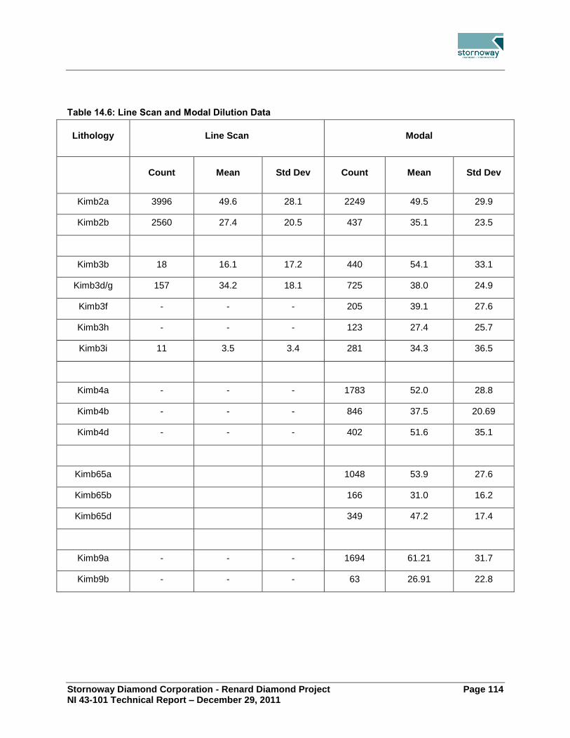
Stornoway Diamond Corporation - Renard Diamond Project Page 114 NI 43-101 Technical Report – December 29, 2011
Table 14.6: Line Scan and Modal Dilution Data
Lithology Line Scan Modal
Count Mean Std Dev Count Mean Std Dev
Kimb2a 3996 49.6 28.1 2249 49.5 29.9
Kimb2b 2560 27.4 20.5 437 35.1 23.5
Kimb3b 18 16.1 17.2 440 54.1 33.1
Kimb3d/g 157 34.2 18.1 725 38.0 24.9
Kimb3f - - - 205 39.1 27.6
Kimb3h - - - 123 27.4 25.7
Kimb3i 11 3.5 3.4 281 34.3 36.5
Kimb4a - - - 1783 52.0 28.8
Kimb4b - - - 846 37.5 20.69
Kimb4d - - - 402 51.6 35.1
Kimb65a 1048 53.9 27.6
Kimb65b 166 31.0 16.2
Kimb65d 349 47.2 17.4
Kimb9a - - - 1694 61.21 31.7
Kimb9b - - - 63 26.91 22.8

Stornoway Diamond Corporation - Renard Diamond Project Page 115 NI 43-101 Technical Report – December 29, 2011
14.4.7 Dry Bulk Density
Table 14.7 summarizes the bulk density results. A single bulk density per facies type is used in this resource evaluation.
Table 14.7: Summarised Density Data
Body Lithology Number of Samples Average
Bulk Density
Standard
Deviation
Renard 2 Kimb2a 110 2.61 0.05
Kimb2b 50 2.73 0.07
Kimb2c 38 2.67 0.07
Renard 3 Kimb3b 11 2.61 0.04
Kimb3c 17 2.65 0.03
Kimb3d+Kimb3g 61 2.74 0.07
Kimb3f 10 2.68 0.04
Kimb3h 2 2.58 0.09
Kimb3i 9 2.75 0.07
Renard 4 Kimb4a 66 2.59 0.05
Kimb4b 20 2.73 0.06
Kimb4c 14 2.59 0.05
Kimb4d 12 2.60 0.04
Renard 65 Kimb65a 7 2.57 0.05
Kimb65b 5 2.72 0.06
Kimb65d 6 2.77 0.08
Kimb65c 6 2.59 0.06
Renard 9 Kimb9a 59 2.56 0.06
Kimb9b 2 2.60 0.07
Kimb9c 9 2.60 0.03
Lynx HK 20 2.54 0.05
Hibou HK 20 2.53 0.08
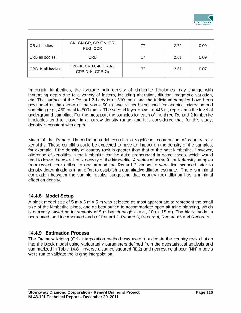
Stornoway Diamond Corporation - Renard Diamond Project Page 116 NI 43-101 Technical Report – December 29, 2011
CR all bodies GN, GN-GR, GR-GN, GR,
PEG, CCR 77 2.72 0.09
CRB all bodies CRB 17 2.61 0.09
CRB+K all bodies CRB+K, CRB+/-K, CRB-3,
CRB-3+K, CRB-2a 33 2.61 0.07
In certain kimberlites, the average bulk density of kimberlite lithologies may change with increasing depth due to a variety of factors, including alteration, dilution, magmatic variation, etc. The surface of the Renard 2 body is at 510 masl and the individual samples have been positioned at the center of the same 50 m level slices being used for ongoing microdiamond sampling (e.g., 450 masl to 500 masl). The second layer down, at 445 m, represents the level of underground sampling. For the most part the samples for each of the three Renard 2 kimberlite lithologies tend to cluster in a narrow density range, and it is considered that, for this study, density is constant with depth. Much of the Renard kimberlite material contains a significant contribution of country rock xenoliths. These xenoliths could be expected to have an impact on the density of the samples, for example, if the density of country rock is greater than that of the host kimberlite. However, alteration of xenoliths in the kimberlite can be quite pronounced in some cases, which would tend to lower the overall bulk density of the kimberlite. A series of some 91 bulk density samples from recent core drilling in and around the Renard 2 kimberlite were line scanned prior to density determinations in an effort to establish a quantitative dilution estimate. There is minimal correlation between the sample results, suggesting that country rock dilution has a minimal effect on density.
14.4.8 Model Setup
A block model size of 5 m x 5 m x 5 m was selected as most appropriate to represent the small size of the kimberlite pipes, and as best suited to accommodate open pit mine planning, which is currently based on increments of 5 m bench heights (e.g., 10 m, 15 m). The block model is not rotated, and incorporated each of Renard 2, Renard 3, Renard 4, Renard 65 and Renard 9.
14.4.9 Estimation Process
The Ordinary Kriging (OK) interpolation method was used to estimate the country rock dilution into the block model using variography parameters defined from the geostatistical analysis and summarized in Table 14.8. Inverse distance squared (ID2) and nearest neighbour (NN) models were run to validate the kriging interpolation.

Stornoway Diamond Corporation - Renard Diamond Project Page 117 NI 43-101 Technical Report – December 29, 2011
Table 14.8: Kriging Parameters
Range Range
Nugget x1 y1 y2 sill1 x2 y2 z2 sill2
Kimb2a 250 4 4 4 245 75 75 50 295
Kimb2b 180 3 3 8 130 30 30 50 100
Kimb3b 600 1 1 10 100 10 10 41 400
Kimb3d/g 380 4 4 4 65 20 20 40 170
Kimb3f 350 8 8 8 250 40 40 40 150
Kimb3h 580 20 19 20 600 20 35 50 200
Kimb3I 580 20 19 20 600 20 35 50 200
Kimb4a 285 45 45 69 170 - - - -
Kimb4b 164 25 25 25 40 45 45 80 90
Kimb4d 1114 21 21 42 192 - - - -
Kimb65a 510 42 30 65 245 - - - -
Kimb65b 18 25 25 25 67 35 35 64 110
Kimb65d 120 10 10 40 10 20 20 83 145
Kimb9a 760 42 42 80 250 - - - -
Kimb9b 400 25 25 50 135 - - - -
14.4.10 Integration Process
For each kimberlite lithology, the undiluted grade for the block was multiplied by the estimate of the dilution for the block. For each rock type, if a factor was required to account for the unmodelled Kimb2c/Kimb3c/Kimb4c/Kimb65c component, this was applied. In the block model the resulting grade was multiplied by the proportion of the rock type in the block, the relevant density was applied to each rock type and the results summed to establish the total carats and tonnes in the block. Available information for the Lynx and Hibou dykes was examined and average grades from the bulk samples assigned as appropriate grades for the bodies.

Stornoway Diamond Corporation - Renard Diamond Project Page 118 NI 43-101 Technical Report – December 29, 2011
Validation 14.5.Amongst many issues checked, dilution is the crucial key to this estimation. In Figure 14.3 and Figure 14.4 estimates of dilution are shown against the measured dilution.
Figure 14.3: Estimated vs. Actual Dilution for Kimb2a
Figure 14.4: Estimated vs. Actual Dilution for Kimb2b

Stornoway Diamond Corporation - Renard Diamond Project Page 119 NI 43-101 Technical Report – December 29, 2011
Diamond Price Estimates 14.6.A valuation of the Renard diamonds was performed under the supervision of WWW International Diamond Consultants Ltd. (WWW) in Antwerp Belgium between May 9th-13th, 2011. The results were announced by Stornoway on June 13, 2011, are presented in Table 14.9 and Table 14.10 and discussed below.
Table 14.9: Renard Kimberlite Pipe Diamond Valuations and Diamond Price Models1
Kimberlite
Body
Weight
of
Valuation
Sample
(Carats)6
September 2009 Re-
Price May 2011 Valuation Diamond
Price
Estimate for
Mine
Planning
Purposes2
Observed
Average
Diamond
Price
(US$/carat)
Diamond
Price
Model
Observed
Average
Diamond
Price
(US$/carat)
Diamond
Price
Model
(US$/carat) (U$/carat)
Renard 2 1580.063 US$108
US$117
US$173
US$182
US$182
(with
sensitivities
of $103 to
$131)
(with
sensitivities
of $163 to
$236)
Renard 3 2,752.264 US$130
US$117
US$171
US$182
(with
sensitivities
of $103 to
$131)
(with
sensitivities
of $153 to
$205)
Renard 4 2,674.495 US$67
US$75
US$100
US$112
US$1647
(with
sensitivities
of $65 to
$82)
(with
sensitivities
of $105 to
$185)
US$164
Renard 65 na US$164
8
Renard 9
Notes 1 As determined by WWW Diamond Consultants International Ltd. at a +1 DTC sieve size cut-off. 2 As recommended by GeoStrat (refer to text Section 14.6). 3 Comprised 1,589.57 cts at the September 2007 valuation. 4 Comprised 2,651.17 cts at the September 2007 valuation. 5 Comprised 2,191.73 cts at the September 2007 valuation.

Stornoway Diamond Corporation - Renard Diamond Project Page 120 NI 43-101 Technical Report – December 29, 2011
6 Carats submitted for 2011 valuation represent large rolled samples derived from bulk sampling, and do not include stones available from the earlier smaller scale sampling.
7 Price recommend for Renard 4 utilizes the recommended WWW Renard 4 value model price combined with Renard 2 + Renard 3 Size Frequency Distribution (SFD), refer to text in Section 14.6.
8 Recommend price utilizes the Renard 2 + Renard 3 Size Frequency Distribution (SFD) and the Renard 4 value model for a conservative Renard 9 and Renard 65 diamond price
Consistent with prior valuations, in this most recent 2011 work, WWW created a single diamond price model for the Renard 2 and Renard 3 valuation samples given the similarity of the diamonds in terms of diamond qualities and size distribution. This base case price model is US$182/carat, a 56% increase compared to the price model of US$117/carat established in September 2009. Also consistent with past practice, a separate diamond price model has been adopted for the Renard 4 valuation sample given its apparently finer distribution of diamond sizes. The Renard 4 base case price model is US$112/carat, a 49% increase compared to the previously established price model of $75/carat. Model price sensitivities are US$163 to US$236/carat for Renard 2, US$153 to US$205/carat for Renard 3 and US$105 to US$185/carat for Renard 4. Diamond price models represent the diamond price that might reasonably be expected based on commercial-scale recoveries of all diamond size classes. WWW’s sensitivity limits are set such that it is highly unlikely that an actual diamond price achieved for each kimberlite body would fall below the "Minimum" sensitivity, but it is possible that the actual diamond price achieved may be higher than the "High" sensitivity number, which is not a maximum price. As recommended by WWW, Stornoway will utilize a base case diamond price model of US$182/carat for the Renard 2 and 3 kimberlite pipes in the financial model of the Renard Feasibility Study. Prior analysis has suggested that the apparently finer size distribution of diamonds in the Renard 4 valuation sample, which accounts for that sample's lower base price model of US$112/carat, is attributable to increased diamond breakage and poor plant performance during recovery. In addition to the recent analysis as described in Farrow (2010) and Lecuyer et al. (2008) an overall large degree of similarity is observed for the Renard 2, Renard 3, and Renard 4 diamond distributions by AMEC (Oosterveld, 2008). WWW stated that Manson (2009) makes a compelling argument that the in-situ size frequency distribution (“SFD”) for Renard 4 is in fact similar to that of Renard 2 and Renard 3 and the difference is due to diamond loss or breakage. If this is the case then the Renard 4 SFD model will be much coarser than the sample SFD and would increase the modelled SFD significantly. WWW therefore created a “high” model using the SFD model for Renard 2 and Renard 3 (WWW, 2011). On this basis, and taking into account alternate interpretations of diamond quality and the compelling discussion regarding size distribution, a diamond price of US$ 164/carat was adopted for Renard 4, which is slightly more conservative than the Renard 2 and Renard 3 diamond price. During the 2010 Resource Update, the Renard 2 and Renard 3 diamond price was adopted for Renard 4, as shown above in Table 14.9. Size frequency analysis of the Renard 9 and Renard 65 samples indicates an overall similarity with the the other pipes of the Renard cluster. The recommended diamond price for Renard 9 and Renard 65 utilizes the Renard 2 + Renard 3 SFD and the Renard 4 diamond value model.

Stornoway Diamond Corporation - Renard Diamond Project Page 121 NI 43-101 Technical Report – December 29, 2011
Table 14.10: Lynx and Hibou Dyke Diamond Valuations and Diamond Price Models1
Kimberlite
Body
Weight
of
Valuation
Sample
(Carats)5
September 2009 Re-
Price May 2011 Valuation Diamond
Price
Estimate for
Mine
Planning
Purposes2
Observed
Average
Diamond
Price
(US$/carat)
Diamond
Price
Model
Observed
Average
Diamond
Price
(US$/carat)
Diamond
Price
Model
(US$/carat) (U$/carat)
Lynx 537.493 US$55
US$57
US$99
US$119
US$119
(with
sensitivities
of $48 to
$85)
(with
sensitivities
of $99 to
$144)
Hibou 771.284 US$38
US$57
US$71
US$118
(with
sensitivities
of $48 to
$85)
(with
sensitivities
of $88 to
$136)
Notes 1 As determined by WWW Diamond Consultants International Ltd. at a +1DTC sieve size cut-off in May 2011. 2 As recommended by GeoStrat. 3 Parcel valued in May 2011 by WWW includes 19 carat parcel of Lynx Boulder Float. 4 Parcel valued in May 2011 by WWW. 5 Carats submitted for May 2011 valuation represent large rolled samples derived from bulk sampling.
In addition to their valuation work on the Renard 2, Renard 3 and Renard 4 diamond samples, WWW also provided an updated valuation for the Lynx and Hibou diamond samples. WWW has recommended a base case modeled price of US$119/carat be adopted for the Lynx diamond sample with sensitivities of US$99 to US$144/carat, and a base case modeled price of US$118/carat be adopted for the Hibou diamond sample with sensitivities of US$88 to US$136/carat. The proposed mine plan for Renard presently does not include a plan to mine the Lynx and Hibou dykes.

Stornoway Diamond Corporation - Renard Diamond Project Page 122 NI 43-101 Technical Report – December 29, 2011
Mineral Resource Classification 14.7.The reported Mineral Resources for the Renard Project kimberlites were constrained by GeoStrat using drill density and sample distribution. Classification of the resources in diamonds is an inclusive process, looking at aspects of geology, grade, revenue, density, diamond size frequency and continuity. For the Renard kimberlite pipes, the Indicated Resource classification incorporates areas where substantial sampling has been undertaken. For Renard 2 this includes the RC, underground bulk samples and microdiamond sampling to 600 m. For the other pipes it is limited to the RC hole depths which indicate grade continuity. These depths are supported by the more extensive core drilling which is sufficient to delineate the resources at an Indicated level from the geological/lithological/volumetric/density aspect. Sufficient carats have been recovered for revenue analysis and support that the revenue is at the Indicated level of confidence for Renard 2, Renard 3 and Renard 4.
14.7.1 Reasonable Prospects of Economic Extraction
Canadian Institute of Mining and Metallurgy (CIM) standards and Securities Commission disclosure regulations require that a mineral resource can only be declared on a mineral deposit which has “reasonable prospects of economic extraction”. Work completed for the Feasibility study supports Geostrat’s opinion that the mineral resource presented herein has reasonable prospects of economic extraction.
14.7.2 Uncertainty of Mineral Resources
Mineral Resources for the Renard Project documented in Section 14 are estimates and no assurance can be given that the anticipated tonnages and grades will be achieved or that the indicated level of recovery will be realized. Market fluctuations and diamond prices may render the mineral resources uneconomic. Moreover, short term operating factors relating to the diamond deposits, such as the need for orderly development of the deposits or the processing of new or different grades of diamonds, may cause any mining operation to be unprofitable in any particular accounting period. Until they are categorized as “Mineral Reserves” under NI 43-101, the known mineralization at Renard is not determined to be economic ore. The Company’s ability to put the Renard Project into production will be dependent upon completion of a bankable feasibility study, receipt of all required permits, and the execution of an IBA with the Cree Nation. In addition, substantial expenditures are required to develop the mining and processing facilities and infrastructure at any site chosen for mining, and depend upon the Company’s ability to raise those funds.
Mineral Resource Statement 14.8.The Mineral Resource Estimate for the Renard Project is summarized in Table 14.11 and Table 14.12.

Stornoway Diamond Corporation - Renard Diamond Project Page 123 NI 43-101 Technical Report – December 29, 2011
The Mineral Resource Estimate takes into account geological, mining, processing and economic constraints and is classified in accordance with the 2005 CIM Definition Standards for Mineral Resources and Mineral Reserves. The Mineral Resource Estimate is based on the continuity of geology between kimberlite at depth and kimberlite nearer surface and the generally low variation in sample results for the different kimberlite phases with depth. GeoStrat notes that there is potential for additional volume at depth for the Renard Project, as the geological models have been constructed conservatively in areas of limited drilling. The Indicated tonnage reported in Table 14.11 and the Inferred tonnage in Table 14.12 lie within the solid model shells. Tonnage and grade estimates include estimation of internal dilution (barren material) within each body.
Table 14.11: January 20111 Indicated
2 Mineral Resources
3 Renard Diamond Project
Deposit Total
Tonnes
Total
Carats
Average
cpht4
Average
Dilution %
Renard 2 17,632,000 18,092,000 102.6 37.4
Renard 3 1,751,000 1,849,000 105.6 36.8
Renard 4 7,246,000 3,813,000 52.6 49.1
Renard 9 0 0 0 0
Lynx 0 0 0 na
Hibou 0 0 0 na
Total 26,629,000 23,755,000 89.2 na
Notes 1 Effective Date is January 24, 2011. 2 Classified according to CIM Definition Standards. 3 The Mineral Resources have reasonable prospects of economic extraction. 4 The diamond size cut off was +1 DTC or +1.18mm square mesh screen.

Stornoway Diamond Corporation - Renard Diamond Project Page 124 NI 43-101 Technical Report – December 29, 2011
Table 14.12: January 20111 Inferred
2 Mineral Resources
3 Renard Diamond Project
Deposit Total
Tonnes
Total
Carats
Average
cpht4
Average
Dilution %
Renard 2 5,208,000 6,142,000 117.9 29.1
Renard 3 542,000 637,000 117.6 39.2
Renard 4 4,756,000 2,087,000 43.9 55.5
Renard 9 5,700,000 2,686,000 47.1 65.4
Renard 65 12,935,000 3,722,000 28.8 48.7
Lynx 1,798,000 1,924,000 107 na
Hibou 178,000 256,000 144 na
Total 31,116,000 17,454,000 56.1 na
Notes 1 Effective Date is January 24, 2011. 2 Classified according to CIM Definition Standards. 3 The Mineral Resources have reasonable prospects of economic extraction. 4 The diamond size cut off was+1DTC or +1.18mm square mesh screen.
Target for Further Exploration (formerly Potential Mineral 14.9.Deposit)
In addition, Targets for Further Exploration (TFFE) were identified on the various kimberlites. [Note: prior to changes in the NI43-101 legislation that came into effect June 30, 2011, the TFFE were known as Potential Mineral Deposits (PMD)]. TFFE are derived from geological volumes based on projection at a standard 85° of the pipe margin in pipes or to within 50 m of known borehole intersections in case of the dykes. These are detailed in Table 14.13 as low and high ranges, both of which are considered to be geologically realistic. Total TFFE was identified as being between 55 and 76 million tonnes, containing between 23.5 and 48.5 million carats of diamonds, at an average grade of 43 cpht to 64 cpht. These were defined on a basis of outcrops, limited delineation drilling and surface sampling. The potential quantity and grade of any target for further exploration is conceptual in nature, there is insufficient exploration to define a mineral resource and it is uncertain if further exploration will result in the target being delineated as a mineral resource.

Stornoway Diamond Corporation - Renard Diamond Project Page 125 NI 43-101 Technical Report – December 29, 2011
Table 14.13: January 2011 Target for Further Exploration1 Renard Diamond Project
Low Range High Range
Deposit Total
Tonnes
Total
Carats
Average
cpht
Total
Tonnes
Total
Carats
Average
cpht
Renard 2 4,012,000 4,132,000 103 4,586,000 8,621,000 188
Renard 3 771,000 825,000 107 1,644,000 2,762,000 168
Renard 4 11,077,000 4,209,000 38 15,300,000 12,087,000 79
Renard 9 3,858,000 1,736,000 45 6,327,000 3,163,000 50
Renard 65 29,517,000 6,789,000 23 41,591,000 13,725,000 33
Lynx 3,089,000 2,966,000 96 3,199,000 3,839,000 120
Hibou 2,745,000 2,855,000 104 2,853,000 4,309,000 151
Total2
55,069,000 23,512,000 43 75,500,000 48,506,000 64
Notes 1 Previously known as Potential Mineral Deposit prior to June 30, 2011 changes to NI43-101 legislation. 2 Totals may not equal the sum of the individuals due to rounding.
Substantial increases to the volumes of the Renard kimberlite bodies, due to additional drilling and subsequent modelling, are responsible for the major differences between the results of the previous Mineral Resource Estimate (Farrow, 2010) and the current estimate (Farrow and Farrow, 2011).

Stornoway Diamond Corporation - Renard Diamond Project Page 126 NI 43-101 Technical Report – December 29, 2011
15.0 MINERAL RESERVE ESTIMATE
Basis of Estimate 15.1.The requirements for Mineral Resources to be converted to Mineral Reserves are that:
Only Measured and Indicated Resources can be included;
The resources are part of a mining plan;
Modifying factors of dilution and mining recovery are applied; and
The mine plan passes an economic test.
Each of these requirements was addressed in establishing the Mineral Reserves for the Renard Project.
As part of the Feasibility Study, a detailed mine plan was developed to extract the Indicated Resources of the Renard Project, dilution and recovery assumptions were applied, and, cut-off grades were calculated using preliminary costs and diamond valuations. AMEC undertook a high level review of the Mineral Resource models and geological wireframes that had been prepared by Geostrat Consulting. The review was completed in sufficient detail to assess whether the Mineral Resource geological and block models were complete, appropriate to the selected mining methods, and suitable to support feasibility study mine planning, such that it would be reasonable for AMEC to rely on them in preparing the underground Mineral Reserve estimates. Based on these review activities, AMEC concluded that the Mineral Resource geological and block models were complete and suitable to support feasibility study mine planning and design. Open pit and underground Mineral Reserves were estimated independently based on criteria specific to each method. A reconciliation of the Mineral Resources included in the open pit and underground mine plans was completed and confirmed that all available resources were included.
Open Pit 15.2.The reserves for the surface mine design are reported according to the Canadian Institute of Mining, Metallurgy and Petroleum’s (CIM) standards. According to these standards, resource model blocks classified as measured and indicated are reported as proven and probable reserves respectively. Owing to the above reporting standards, Inferred Resources cannot be included as reserves and so have not been included in the life of mine (LOM) schedule. No resource blocks are classified as measured and therefore no part of the Mineral Reserve classifies as proven. The total probable Mineral Reserve includes an ore dilution factor and an ore recovery factor to estimate a recoverable mining reserve.

Stornoway Diamond Corporation - Renard Diamond Project Page 127 NI 43-101 Technical Report – December 29, 2011
The ore outline mining shapes consisted of expanding the modelled kimberlite solids to incorporate a 1 m dilution envelope (Figure 15.1). Specific dilution factors were estimated for each kimberlite orebody through compilations performed on a bench by bench basis. The dilution envelope is assumed not to contain diamonds and is therefore considered to be zero grade.
Figure 15.1: Illustration of Dilution Envelope
The dilution factors by bench per kimberlite pipe are shown in the following tables (Table15.1 and Table 15.2).
Table 15.1: R2 & R3 Dilution by Bench
R2
R3
Bench Level
Bench Dilution
Bench Level
Bench Dilution
508 -
508 32%
498 36%
498 14%
488 9%
488 11%
478 8%
478 11%
468 8%
468 11%
458 8%
458 14%
448 10%
448 15%
438 8%
438 8%
428 7%
428 6%
418 4%
418 4%
408 2%
413 2%
403 1%

Stornoway Diamond Corporation - Renard Diamond Project Page 128 NI 43-101 Technical Report – December 29, 2011
Table 15.2: Average Dilution Factors
Dilution R2 R3
In-situ Ore Tonnage 1,276,881 681,007
Diluted Ore Tonnage 1,367,224 752,760
Dilution Factor 7.1% 10.5%
A 96% mine recovery factor is then applied to account for ore missed at the edge of the orebody. It is also possible to lose some of the ore during transportation to the process plant due to misdirected loads or operator error.
Underground 15.3.15.3.1 Estimation Procedure
The first step in the estimation of the Mineral Reserves was to create 3-D shapes for each of the stopes based on the Mineral Resource model and the planned mining method. The criteria used was to create practical shapes that were compatible with the planned development of the drawpoint levels and drill drifts, the drill patterns available, the type of drilling equipment selected, and likely post blast outlines. The outlines of the pipes in some areas were irregular and in these areas practical (smoothed) mining outlines were created, which typically encapsulated some waste rock and occasionally excluded some kimberlite. The stope outlines were created by cutting a series of resource plans every 5 m vertically and then planning and digitizing a stope outline for each level. The individual stope outlines, created over the full height of each pipe, were then imported into Vulcan software and a 3-D solid was created. These stope solids were then subdivided into stopes by mining zone and then further subdivided into undercuts and main stope body. The main stope body was then further subdivided to coincide with potential sequencing of blasting and production. A number of remnant solids were also created for kimberlite left in the walls of the open pit. For the undercuts at the drawpoint levels, the design of the drawpoint troughs is fairly complex, so a detailed solid of this area of the stope was created in AutoCAD and then combined with the stope shapes and imported into Vulcan. As part of this process, the block model grades within the pipes were examined and, while there was some variation in grade across the levels, in AMEC’s opinion there wasn’t any real opportunity, given that BHS is a bulk mining method, to eliminate local areas of lower grade kimberlite from the stope shapes. The tonnage and grade of all the Mineral Resources contained within each stope shape was calculated using the resource block model and Vulcan software. The stopes included in the underground Mineral Reserves are shown in Figure 15.2.

Stornoway Diamond Corporation - Renard Diamond Project Page 129 NI 43-101 Technical Report – December 29, 2011
Figure 15.2: Stopes Included in the Underground Mineral Reserves

Stornoway Diamond Corporation - Renard Diamond Project Page 130 NI 43-101 Technical Report – December 29, 2011
15.3.2 Modifying Factors
As discussed in Section 15.3.1 the stope shapes include any waste contained within them as internal dilution. The modifying factors of mining recovery and external dilution have been applied to the contained Mineral Resource and waste in the stope shapes. The assumptions of recovery and dilution for BHS mining used for this study are:
Mining recovery = 85%
Dilution = 14%
These factors were applied to the complete BHS stopes including the undercut troughs. For sublevel retreat mining at the very bottom of the Renard 2 and Renard 4 pipes, the assumptions for recovery and dilution are:
Mining recovery = 50%
Dilution 14%
The grade of all dilution has been assumed to be zero.
Considerations for recovery and dilution estimate assumptions for BHS mining are:
With BHS, the first 35% of the production is swell, which will have very low dilution. When the stope is full of blasted ore the first 50% to 60% of the drawdown will also have very low dilution and high recovery. When backfill waste starts mixing with the ore as it is drawn down, dilution for each tonne drawn will start increasing significantly. The build-up of the dilution and recovery assumptions are shown in Table 15.3.
Table 15.3: Assumptions for Dilution and Recovery of BHS Mining
Drawdown Stage in
Stope
Portion of Total Ore in Stope Recovery
Estimates
Dilution
Estimates
Shrinkage Blasting 35% 98% 2%
Middle Drawdown 32% (50% of ore remaining after blasting) 90% 6%
Final Drawdown 31% (47% of ore remaining after blasting) 72% 30%
Final Clean-up 2% (3% of ore remaining after blasting) 40% 100%
Subtotal 100% 86% 14%
Mining losses1
1.0% -
Total 85% 14%
Note 1: mining losses due to (a) irregular geometry of the walls, (b) miss-holes and blasting problems, (c) ore
stranded above arches in bottom drawpoint level, (d) failure of brows in drawpoints.

Stornoway Diamond Corporation - Renard Diamond Project Page 131 NI 43-101 Technical Report – December 29, 2011
Placement of drawpoints and planning of drawdown is critical to achieve mass flow and minimize “rat-holing” of the blasted ore in the stope during drawdown.
It is known that the CCR and CRB units, which surround the pipes in many locations, contain diamonds however the grade is unknown, consequently no grade has been assumed for the dilution. Further, much of the dilution will come from the open pit waste rock to be placed on top of the blasted kimberlite, and this will contain no grade.
At the very bottom level (610L for Renard 2 and 280L for Renard 4), the kimberlite remaining on the underside of the drawpoint troughs will not be recovered as part of BHS mining. To recover this ore, sublevel retreat mining (SLR) will be used at the very end of the mine life. Upholes will be drilled from all the drawpoints and scram drifts located below the troughs and cones and then the holes will be blasted and the ore mucked in a retreat fashion. The mining recovery for this final stage of mining has been assumed to be 50%. The dilution and recovery factors as listed in Table15.3 were applied on a stope-by-stope basis to calculate the reserve for each stope. A final step was to review the mineability and the calculated Mineral Reserve tonnes and grade for each stope. Three stope blocks totalling 278,000 tonnes, located just outside the open pit stope walls, were initially included in the Mineral Reserve but upon review were excluded since they were judged too problematic to mine. The grade of all the stopes was compared to the cut-off grade (37.6 cpht for Renard 2/Renard 3 and 30.4 cpht for Renard 4) and all stopes were found to exceed this cut-off.
Mineral Reserves 15.4.15.4.1 Open Pit Mineral Reserve Statement
The total open pit probable Mineral Reserve is estimated at 2 million tonnes of ore with an average diluted grade of 0.94 cpt for 1.91 million carats. The Renard 2 pipe has the highest average diamond grade at 0.95 cpt followed closely by Renard 3 at 0.93 cpt. The open pit Mineral Reserves are summarized by bench in Table 15.4 and by kimberlite pipe in Table 15.5.

Stornoway Diamond Corporation - Renard Diamond Project Page 132 NI 43-101 Technical Report – December 29, 2011
Table 15.4: R2/R3 Open Pit Mineral Reserves by Bench
Bench Level
Ore Tonnes
Carats Avg. grade
OVB Tonnes
Waste Rock
Tonnes
Strip Ratio
(OVB + WST)/ ORE
Total Tonnes
(x 1000) (x 1000) (cpht) (x 1000) (x 1000) (x 1000)
518 - - - 25 0.9 - 26
508 1.3 0.7 53,8 890 172 827.01 1,063
498 37 26 70,3 1,030 875 52.02 1,942
488 154 141 91,6 314 1,511 11.84 1,978
478 266 252 94,7 17 1,479 5.63 1,762
468 271 255 94,1 - 1,387 5.11 1,658
458 259 241 93,1 - 895 3.45 1,155
448 260 244 93,8 - 708 2.73 968
438 246 243 98,8 - 400 1.63 645
428 229 224 97,8 - 274 1.19 503
418 177 168 94,9 - 100 0.56 276
408 115 102 88,7 - 50 0.43 165
398 20 16 80,0 - 6 0.28 26
Total 2,035 1,913 94.0 2,277 7,857 4.98 12,168
Table 15.5: Open Pit Mineral Reserves by Category by Kimberlite Pipe
Pipe Classification Tonnes (x 1000)
Grade (cpht)
Carats (x 1000)
R2 Probable 1,312 94.6 1,242
R3 Probable 723 92.8 671
Total Probable 2,035 94.0 1,913

Stornoway Diamond Corporation - Renard Diamond Project Page 133 NI 43-101 Technical Report – December 29, 2011
15.4.2 Underground Mineral Reserve Statement
The underground Mineral Reserves are summarized by pipe and mining zone in Table 15.6. All Mineral Reserves are in the “probable” category. Of the three pipes in the Mineral Reserve, Renard 2 contains 78% of the tonnes and 85% of the carats, Renard 4 contains 17% of the tonnes and 10% of the carats and Renard 3 contains 5% of the tonnes and carats.
Table 15.6: Underground Mineral Reserve Statement
15.4.3 Consolidated Mineral Reserve Statement
A consolidated summary of the Mineral Reserves for the Renard Project including both underground and open pit mining is presented in Table 15.7. The table includes a breakdown of the Mineral Reserves by pipe and mining method as well as totals by pipe and mining method. In summary, 89% of the diamonds are mined by underground methods and overall 83% of the diamonds are contained in the Renard 2 kimberlite pipe.

Stornoway Diamond Corporation - Renard Diamond Project Page 134 NI 43-101 Technical Report – December 29, 2011
Table 15.7: Mineral Reserves Summary – Open Pit and Underground
Mine Probable Reserve (t x 1000)
Grade (cpht)
Carats (x 1000)
% of Total Tonnes
% of Total Carats
Renard 2 Open Pit 1,313 94.6 1,242 5.7% 6.9%
Renard 3 Open Pit 723 92.8 671 3.1% 3.7%
Renard 2 Underground 16,297 83.8 13,664 70.7% 75.9%
Renard 3 Underground 1,003 84.1 843 4.3% 4.7%
Renard 4 Underground 3,720 42.4 1,578 16.1% 8.8%
Total 23,055 78.1 17,998 100.0% 100.0%
Subtotals by Pipe and Mining Method
Renard 2 Pipe 17,610 84.6 14,906 76.4% 82.8%
Renard 3 Pipe 1,725 87.7 1,514 7.5% 8.4%
Renard 4 Pipe 3,720 42.4 1,578 16.1% 8.8%
Open Pit 2,035 94.0 1,913 8.8% 10.6%
Underground 21,020 76.5 16,085 91.2% 89.4%
Note: All Mineral Reserves are in the Probable Category
15.4.4 Reconciliation of Mineral Resources and Reserves
A reconciliation of Mineral Resources and Mineral Reserves is shown in Table 15.8.
Table 15.8: Reconciliation of Mineral Resources and Mineral Reserves
Mineral Resources
1,2 Indicated (t x 1000)
Grade (cpht)
Carats (x 1000)
% of Total Tonnes
% of Total Carats
Renard 2 17,632 102.6 18,092 Renard 3 1,751 105.6 1,849 Renard 4 7.246 52.6 3,813 Total 26,629 89.2 23,755 100.0% 100.0%
Resources in Mineral Reserves (probable)
Renard 2 17,339 102.6 17,782 Renard 3 1,535 110.1 1,690 Renard 4 4,112 49.0 2,015 Sub Total 22,986 93.5 21,487 86% 90%
Excluded Resources
Stopes & Crown Pillar 3,335 61.1 2,039 13% 9%
Outside Stope Boundaries 307 74.3 228 1% 1%
Sub Total 3,642 62.2 2,267 14% 10%
Total 26,629 89.2 23,755 100% 100%
Note: 1 Renard Mineral Resource Update - February 3, 2011 2 Includes both Open Pit and Underground Mining
Stornoway Diamond Corporation - Renard Diamond Project Page 135 NI 43-101 Technical Report – December 29, 2011
Risk to Mineral Reserves 15.5.15.5.1 Open Pit Risks
The risk to the open pit Mineral Reserves is minimal in that the open pits are small, relatively shallow and represent only 11% of the overall reserve. Mining dilution remains a risk since ore/waste separation will rely on visual placement of dig limits by experienced geologists.
15.5.2 Underground Risks
The main risks to the underground Mineral Reserves are higher dilution and lower recovery than planned. Ore drawdown management during production is critical to limiting dilution and maintaining high recovery. A key aspect of managing drawdown is maintaining an even drawdown over the entire blasted ore column in the stope to promote mass flow of the ore. One of the risks resulting from poor draw management is the development of rat-holes above individual drawpoints, ahead of their neighbours, right up to the waste backfill placed on top of the blasted ore. A good drawdown plan in combination with strict draw procedures and regular monitoring is required for success. Identifiable markers placed in the blasted ore, either via placement in blastholes or on drill levels will provide good data on the effectiveness of the drawdown system.

Stornoway Diamond Corporation - Renard Diamond Project Page 136 NI 43-101 Technical Report – December 29, 2011
16.0 MINING METHODS A mine plan has been developed to exploit the Indicated Resources in the Renard 2, Renard 3 and Renard 4 kimberlite pipes. The mine plan for Renard 2 and Renard 3 combines open pit and underground mining methods with the pit depth determined through a trade-off study between open pit and underground mining costs. The Renard 4 mine plan employs underground methods only. Since the Renard 4 kimberlite is located below Lake Lagopède, a 100 m thick crown pillar will be maintained throughout the life of mine. Mine operations will commence at Renard 2 and Renard 3 with open pit mining and preparation of the underground mine development and infrastructure. Following completion of the open pit at Renard 2 and Renard 3, the underground mine will be extended to surface through the pit floor. Waste rock from the open pit and underground development will be placed into the Renard 2 and Renard 3 underground workings via the open pit to provide support for the stope walls during mining. Waste material to support the Renard 4 underground stopes will be backfilled through backfill raises from surface. The mine design was developed by AMEC (underground) and G Mining Services Inc. (open pit). The overburden slope assessment was performed by Golder Associates and the rock mechanics and hydrogeology elements of the mine design were supplied by Itasca Consulting Canada Inc. Cementation Canada Inc. provided the shaft and hoisting facilities design.
Overburden Pit Slope Assessment 16.1.This section summarizes the overburden slope assessment used to provide guidelines on the overall slope design for the open pits. The design of the open pits is discussed in Section 16.4. The stability analysis of the overburden slopes for the open pit portions of Pit R2/R3 was performed. The geotechnical properties and parameters for the overburden used in the analyses were based on the geotechnical investigations discussed in Section 18.1. The overburden thickness over Pit R2/R3 was determined with a model developed using the exploration drilling logs. The overburden thickness ranges from 0 to 27 m with an average of about 10 m. A stability analysis for Pit Renard 65 was not performed. Similar soil conditions are expected; however, soil thickness is expected to be less. The overburden slope configuration discussed below is considered to be applicable to Renard 65; however, a geotechnical inspection of the site-specific conditions is required during excavation to confirm the applicability of the overburden slope configuration. The analysis did not include the section of the pit perimeter within the small lake as information on the soil conditions in the lake is unavailable. A two-dimensional stability assessment was performed. Selected cross-sections of differing overburden thicknesses were analysed. The position of the groundwater table was varied to assess its effect on the stability of the slopes. The groundwater level used in the assessment varied between El. 504 m and El. 514 m. The range of groundwater levels is based on results of site-specific monitoring. The stability of the slopes is affected by the overburden conditions (thickness, stratigraphy, strength, etc.) and the position of the groundwater table. The typical overburden slope
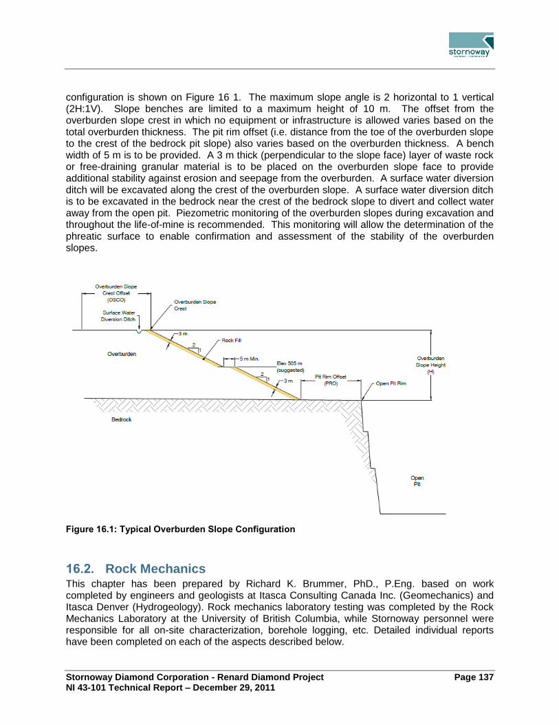
Stornoway Diamond Corporation - Renard Diamond Project Page 137 NI 43-101 Technical Report – December 29, 2011
configuration is shown on Figure 16 1. The maximum slope angle is 2 horizontal to 1 vertical (2H:1V). Slope benches are limited to a maximum height of 10 m. The offset from the overburden slope crest in which no equipment or infrastructure is allowed varies based on the total overburden thickness. The pit rim offset (i.e. distance from the toe of the overburden slope to the crest of the bedrock pit slope) also varies based on the overburden thickness. A bench width of 5 m is to be provided. A 3 m thick (perpendicular to the slope face) layer of waste rock or free-draining granular material is to be placed on the overburden slope face to provide additional stability against erosion and seepage from the overburden. A surface water diversion ditch will be excavated along the crest of the overburden slope. A surface water diversion ditch is to be excavated in the bedrock near the crest of the bedrock slope to divert and collect water away from the open pit. Piezometric monitoring of the overburden slopes during excavation and throughout the life-of-mine is recommended. This monitoring will allow the determination of the phreatic surface to enable confirmation and assessment of the stability of the overburden slopes.
Figure 16.1: Typical Overburden Slope Configuration
Rock Mechanics 16.2.This chapter has been prepared by Richard K. Brummer, PhD., P.Eng. based on work completed by engineers and geologists at Itasca Consulting Canada Inc. (Geomechanics) and Itasca Denver (Hydrogeology). Rock mechanics laboratory testing was completed by the Rock Mechanics Laboratory at the University of British Columbia, while Stornoway personnel were responsible for all on-site characterization, borehole logging, etc. Detailed individual reports have been completed on each of the aspects described below.

Stornoway Diamond Corporation - Renard Diamond Project Page 138 NI 43-101 Technical Report – December 29, 2011
16.2.1 Site Investigations
Various field investigations for the feasibility level study have been conducted (by others) since 2005. These included on site geological mapping (both at surface and underground), and several campaigns of geomechanical data collection, including collecting data from oriented drill holes. During the 2009 drilling program a total of 24 geomechanical/exploration boreholes were drilled between June and September for a total of 12,717 m. Of the 24 drill holes, 13 were oriented for further geomechanical investigation. During the 2010 field program a total of 36 geomechanical/exploration boreholes were drilled between February and November for a total of 7367 m. All 36 boreholes were oriented for further geomechanical investigation. A select group of drill holes from past drill programs (prior to 2009) were chosen for supplementary geomechanical study and were updated to the same set of core logging standards as in recent drill programs. The updated drill holes were then added to the geomechanical database. Geomechanical data was collected by re-examining drill core from 80 drill holes, a total of 20,105 m. All recovered core was photographed and logged. A series of laboratory tests, on selected core samples, were undertaken at the Rock Mechanics Laboratory at UBC.
16.2.2 Laboratory Testing and Geomechanical Database
The descriptions, terms and standards used by Stornoway to construct the laboratory testing and geomechanical database follow the terminology recommended by the International Society for Rock Mechanics (ISRM) and in particular the Rock Characterization and Testing: ISRM Suggested Methods (1981). The geomechanical field assessment identified the following geomechanical units for the purposes of mine design:
Blue Massive Volcaniclastic Kimberlite (MVK-Kimb) is extensively altered, generally massive. This blue to blue–green rock is comprised of olivine, juvenile clasts and country rock xenoliths that are poorly sorted, typically loosely packed and less commonly clast supported and set within a highly altered interclast matrix. Country rock xenoliths are comprised of locally derived granite and gneiss that are fresh to moderately altered.
The Brown Coherent Kimberlite (CK-Kimb is a moderately altered, massive and texturally variable unit that displays both coherent and less common volcaniclastic (i.e. TKB) textures. Macroscopically, the Brown CK is pale brown to black and is comprised of two generations of olivine set within a crystalline groundmass with common country rock xenoliths that typically show significant reaction to the host kimberlite. Country rock xenoliths include both granitoid and gneiss, although the latter predominates.
Coherent Kimberlite (CK - Kimb) occurs in the form of late stage dykes and irregular intrusions and both are classified as HK. HK dykes are found throughout the body and typically occur along contacts between types of main pipe infill, along the pipe walls and throughout the marginal breccias. Dykes range in thickness from a few centimetres to 1m and contacts are often characterized by flow alignment of elongated minerals and carbonate veining. The HK is dark green to black and is comprised of two generations of

Stornoway Diamond Corporation - Renard Diamond Project Page 139 NI 43-101 Technical Report – December 29, 2011
olivine (macrocrysts and phenocrysts) that are evenly distributed and set within a homogeneous, crystalline groundmass.
Country Rock Breccia (CRB) can encompass both brecciated gneiss or brecciated granite or pegmatite. All types are present with the CRB of the Renard units. The granitic-type is most common. It is described as rock that consists of more than 95% country rock fragments with < 5 % kimberlite component.
Cracked Country Rock (CCR/BCR) is fractured country rock with varying degrees of fracturing. This breakage of this country rock can be related to kimberlite emplacement - whether as emplacement of the kimberlites or of a peripheral HK dyke.
Fresh, competent, fine grained, banded, quartz-feldspar-biotite gneiss with less common coarse grained sections with less banding (GN).
Fresh, competent, equigranular granite (GR). Primary mineralogy includes: quartz, feldspar, and biotite.
Fresh, competent, equigranular pegmatite (PEG). Primary mineralogy includes: quartz, feldspar, and biotite.
Selected samples from each borehole and rock type were collected for laboratory testing. All samples were tested at the UBC Rock Mechanics Laboratory in Vancouver. Laboratory testing included triaxial, uniaxial compression (including modulus of elasticity) and Brazilian indirect tension tests on intact rock samples. The laboratory tests were complemented by direct shear tests on rock fractures from core. Slake durability tests were also undertaken for the kimberlites.
16.2.3 In Situ Stress
During the early stages of design it is necessary to have reasonable estimates of in situ stress in order to provide the required input to numerical stress analysis models. Stresses were selected for the Renard Project based on information available from the World Stress Map. The current design considers a conservative range of stresses, within the range for comparable mines to Renard in the Canadian Shield.
16.2.4 Cavability
Prior to the analysis, Itasca reviewed the provided rock mass classification results. Based on the empirical and laboratory rock data it was decided that all kimberlite units could be treated as equivalent in their geomechanical properties. Furthermore, there was no major variation in rock quality with depth within the kimberlites. The results of the slake durability tests justified the assumption that only slight weathering was to be expected in the kimberlites. The Mine Rock Mass Rating (MRMR) empirical approach (Laubscher, 2000) was employed to determine whether the kimberlite domains are amenable to caving. It was concluded that the Renard orebodies will require some form of blast-assisted caving method. Consistent and predictable natural caving is unlikely to occur even when the undercut footprints reach the boundaries of the kimberlite orebodies.

Stornoway Diamond Corporation - Renard Diamond Project Page 140 NI 43-101 Technical Report – December 29, 2011
16.2.5 Presence of Faulting
Investigations into the presence of faults started with a review of prior work undertaken at Renard. This was then complemented by orthophoto lineament analysis in July 2010, and ground truthing and structural mapping in October 4-13, 2010. Datamine modelling of faults (as wireframe surfaces incorporating drill hole fault intercepts) was carried out in November 2010. The modeling of faults was revised in May 2011 based on validations carried out by Stornoway.
16.2.6 Pit Slope Assessment
A series of open pit bedrock slope analyses for the Renard 2 and Renard 3 pits were carried out in 2010. Following a series of iterative analyses the slope stability analysis was revised to take into consideration the updated and optimised final layout, geology and wall orientations of the pits.
16.2.7 Subsidence Assessment
Caving-style mining methods can pose a significant risk related to shaft and surface infrastructure stability since mining induced subsidence could occur as a direct result of these methods. For this reason any critical life of mine infrastructure should be located outside of the influence of mining-induced subsidence. Subsidence limits have been determined at Renard with the main goal of validating the proposed shaft location. Subsidence limits were initially established using an empirical approach. A break angle of 85º was determined for the limit of discontinuous subsidence and a limit angle of 80º was assumed as the limit of continuous subsidence. These limits were subsequently checked using a conservative numerical modelling approach which confirmed the angles. Furthermore, analogues to similar Kimberlite deposits were investigated. Based on the empirical and numerical analyses, as well as the analogue deposits, the subsidence limits that have been determined at this stage of study appear to be adequate. As more information becomes available, the analyses should be revisited to ensure these limits will still be valid, particularly at the start of the detailed engineering and execution phases.
16.2.8 Ground Support Standards
The design of ground support for Renard was mostly based on the empirical guidelines published by Barton (2002) and Grimstad and Barton (1994). These guidelines are based on rock mass quality, size of the opening, and intended use of the excavation. The prescribed Ground support specifications were based on standards currently adopted in Canadian hard rock mines and are in compliance with good engineering practice.
16.2.9 Crown Pillars
The Renard 4 and Renard 9 kimberlite pipes are below a lake. Consequently it is important to ensure the stability of the Renard 4 and Renard 9 crown pillars since an uncontrolled failure could lead to water inflow into the mine during production. This would represent a significant risk to the safety of personnel working underground.

Stornoway Diamond Corporation - Renard Diamond Project Page 141 NI 43-101 Technical Report – December 29, 2011
The stability of the crown pillars was initially determined by the empirical approach proposed by Carter (1992). This approach indicated that a crown pillar of at least 100 m thick was necessary to mitigate the risk of crown failure. Because of the importance of the stability of the crown pillars, a 3D global stress numerical modelling exercise was also undertaken. The modelling that was conducted for the crown pillar in the Renard 4 pipe indicates that under base case assumptions the crown pillar is stable. It was further shown that within the range of reasonable assumption with regards to material properties or stress, there are combinations in which the crown pillar is unstable. The greatest sensitivity in the modelling performed to date is the presence of a horizontal stress at surface. The models suggest that if a flat-back profile were to be used, the depth of failure into the crown pillar will be between 25% and 35% of the span of the orebody. This coincides well with the general rule of thumb in which arching is assumed to occur at 1/3 of span. The back of the stope should, within reasonable bounds, be formed to create such an arch with the blasted profile to limit the ability of the rockmass to define its own stable arch (which can be quite different depending on local jointing). The peak of the arch should not be above the 100m limit defined by the crown pillar.
16.2.10 Limitations
It must be understood that there are limitations in the ability of numerical model results to assess all potential failure modes (effect of faults, effect of rockmass variability, the effect of draw, and the stabilizing effect of leaving ore in the stope are some examples of factors beyond the explicit capabilities of the models run for this Project to date). Further work should be performed to reduce the uncertainties in the analysis and to examine other potential modes of failure. This could be done in more detailed engineering studies at a later stage of the Project and would include the following.
An analysis to represent the effects of jointing on the rockmass and the effects of major faults either through the Ubiquitous Joint Rockmass Model in FLAC3D or by using 3DEC;
An analysis to consider rockmass variability in which the entire spectrum of rockmass strengths is respected in the model in a statistically valid way; and
If additional faults are found to intersect the region of the Renard 2 pipe, they should be explicitly considered in both the stress modelling and the hydrogeology modelling.
As underground experience is gained at this mine site, these analyses should be continually reviewed to determine if they are still valid over time and to ensure that new information is properly considered into the analysis.
Hydrogeology 16.3.Hydrogeological analyses were completed by Itasca Denver, Inc., in coordination with Itasca Consulting Canada, Inc., (Itasca). The work included: Compiling the existing hydrogeologic data, constructing a numerical, three-dimensional (3-D) groundwater flow model of the site, and

Stornoway Diamond Corporation - Renard Diamond Project Page 142 NI 43-101 Technical Report – December 29, 2011
estimating the potential groundwater inflows to the mine working for the feasibility case mine plan. The geometry of the open pits and underground mine workings was provided by Stornoway. The boundaries of the groundwater flow model domain were selected far away from the mining area where the hydraulic stress induced by mining is insignificant. The water levels of the major lakes were obtained from Stornoway. During 2010, WESA conducted packer testing in two existing boreholes that were selected by Stornoway and Itasca for the purpose of determining the hydraulic conductivity of the rock units. Data was also obtained from various sources, including the previous hydrogeologic field investigations that have been conducted at the Renard site (by GENIVAR, WESA, and Roche) between 2005 and 2010. The hydraulic conductivity of the country rock generally decreases with depth, as expected, but shows high variability within 50m of the ground surface. The groundwater flow model constructed for this investigation utilises the numerical code MINEDW (Azrag et al., 1998) developed by Itasca, which solves 3-D groundwater flow problems with an unconfined (or phreatic) surface using the finite-element method. MINEDW has several attributes that were specially developed to address conditions often encountered in mine dewatering. The modelling code has been used and verified for numerous mine dewatering projects throughout the world. The excavation of open pits, ramp, shaft, and the draw drifts of the underground mine was simulated according to the mining schedule. The subsidence and crack zones associated with underground mining were also simulated. These regions were simulated as areas of enhanced hydraulic conductivity values that develop over time, according to the mining schedule.
16.3.1 Prediction of Inflow
Three predictive simulations were conducted, including a base case scenario and two additional scenarios designed to assess the effects of uncertainties in the key model parameters. The predicted maximum inflow rate is approximately 2,700 m3/day. Except for the elevated inflow rate during the short period of simultaneous Renard 2, Renard 3, and Renard 5 open-pit/underground mining, the total inflow rates for most of the mining years are in the range of 1,200 to 1,500 m3/day. It was found that the predicted inflow is highly sensitive to the hydraulic conductivity of the country rock. Increasing the hydraulic conductivity value by one order-of-magnitude would result in the predicted inflow rate three times greater than the value predicted from the base case.
16.3.2 Limitations
The confidence level of the groundwater flow model prediction depends on the available hydrogeologic data obtained at the site. Currently, there are limited data on the hydrogeologic conditions of both the overburden and the country rock at the site, the interaction between the surface-water bodies and the groundwater system, and the hydrogeologic conditions of the

Stornoway Diamond Corporation - Renard Diamond Project Page 143 NI 43-101 Technical Report – December 29, 2011
faults. The model used the existing data in the predictive simulations, the results of which are subject to change depending on any new data collected in future investigations. These limitations should be addressed in future model updates.
Open Pit Design 16.4.The mining strategy for the Renard orebodies consists of recovering the upper portions of Renard 2 and Renard 3 through open pit mining methods and the deeper portions of Renard 2, Renard 3 and Renard 4 using an underground blasthole shrinkage mining method. The size of the open pit was established through a trade-off study that optimized the profit from mining by open pit versus underground mining techniques. Material will be mined from the Renard 65 kimberlite body to supply construction aggregates and underground backfill material during operation once the surface waste rock stockpiles are exhausted. Country rock from the Renard 65 pit will be used as backfill and aggregate while the kimberlite, which can be reclaimed for processing in the future, will form the platform of the ore stockpile. The resulting Renard 65 pit will be used as a catch basin to manage water on the Project site.
16.4.1 Open Pit Optimization
Open pit optimization was carried out using the Whittle software package implementing the Lerch-Grossman algorithm. The Whittle optimizations were performed using the Renard 2010 resource model provided by GeoStrat Consulting Services Inc. This model was used to produce an updated mineral resource estimate which was included in a press release by Stornoway on January 24, 2011. The NI 43 101 technical report was filed with SEDAR on February 7, 2011. This feasibility level study only considers mineralization classified in the Indicated Resource category which limits open pit mining to the Renard 2 and Renard 3 kimberlite ore bodies. A mining dilution factor was estimated for each pipe by including a 1 m envelope around the ore. The resulting dilution factor, which was employed in the optimization process, was utilized to calculate the diluted grade. As the Renard 2 and Renard 3 open pits merge on surface, an average dilution factor of 10% was used in the optimization process. A 96% mine recovery was applied to account for ore misdirected or missed at the edge of the ore body. The optimization parameters utilized to generate the Whittle shells are summarized in Table 16.1. These parameters were based on preliminary operating cost estimates which were subsequently refined during the course of the Feasibility Study.

Stornoway Diamond Corporation - Renard Diamond Project Page 144 NI 43-101 Technical Report – December 29, 2011
Table 16.1: Summary of Open Pit Optimization Parameters
Parameters
Renard 2 Renard 3
Diamond price US$/carat 139
Exchange rate C$/US$ 1.00
Selling Cost % 3.0%
IBA payment % 1.0%
Royalty % 2.0%
Metallurgical recovery % 100%
Open pit mining dilution % 10%
Open pit mining recovery % 96.0%
Total processing cost C$/t processed 12.45
G&A cost C$/t processed 13.68
Total ore based cost C$/t processed 26.13
Cut-off grade cpt 0.21 0.19
Reference mining cost
Owner
Kimberlite ore C$/t mined 3.60
Granite & gneiss waste rock C$/t mined 3.45
Overburden C$/t mined 2.90
Incremental bench cost C$/t mined/10m 0.045
Whittle overall slope angles
Renard 2 Renard 3
Kimberlite ore Degrees 45
Granite & gneiss waste rock Degrees 45
Overburden Degrees 20
The optimum pit size selected to guide the pit design yielded an estimated incremental mining cost per tonne of ore equal to C$28.38/t. The optimum pit shell was the first shell to yield a higher cost than that achievable using the estimated blasthole shrinkage mining cost C$23.13/t. The optimum pit shell is presented in Table 16.2.
Table 16.2: Summary of Optimal Shell used for Detailed Pit Design
Whittle Results R2/R3
Shell number 6
Revenue factor 0.48
Total tonnage Mt 9.20
Waste tonnage Mt 7.30
Ore tonnage Mt 1.90
Diamonds carats 1,776,616
Grade cpt 0.94
Strip ratio Mt:Mt 3.85 : 1

Stornoway Diamond Corporation - Renard Diamond Project Page 145 NI 43-101 Technical Report – December 29, 2011
16.4.2 Bench Geometry
Bench heights of 10 m were selected to facilitate efficient drilling and blasting activities. The loading units will mine the benches in two 5 m high cuts. The pit slope profile was determined using geotechnical recommendations from Golder Associates (overburden) and Itasca Consulting Canada Inc. (bedrock). The modelled overburden thickness varies from 5 m at the edges to > 25 m over the center of the orebodies. The slope configuration recommendations vary based on overburden thickness and are presented in Table 16.3.
Table 16.3: Overburden Slope Configuration Recommendations (refer to Section 16.1)
OVB slope height
(m)
Overburden Slope Configuration
Upper slope (max 10 m)
Berm width (m) min.
Lower slope
Min OVB slope crest
offset
Min pit rim offset (m)
0 - 6 2H : 1V --- --- 10 8
6 - 10 2H : 1V --- --- 10 8
10 – 20 2H : 1V 5 2H : 1V 20 15
> 20 2H : 1V 5 2H : 1V 20 20
Itasca was tasked with investigating the geotechnical parameters, as they relate to mining, and to recommend feasibility level slope angles for the open pits. Itasca’s pit slope recommendations did not involve geotechnical domains therefore the pit slope profiles are uniform for all pit walls and for all the pits studied. The recommended rock slope configuration is presented in Table 16.4.
Table 16.4: Rock Slope Configuration Recommendations (Itasca Consulting)
Pit
Rock Slope Configuration
Final bench height (m)
Catch bench width (m)
Bench face angle (°)
Inter-ramp angle (crest to crest)
R2 20 9.0 80 57.9
R3 20 9.0 80 57.9
16.4.3 Ramp and Haul Road Design
The ramp was designed to accommodate double lane traffic. The largest equipment considered for the Project was a 60-ton class rigid truck. The maximum ramp gradient is 10%. Single lane ramps are used to access the pit bottoms. Out-of-pit haul roads are designed for double lane traffic. A road network will connect the pits to the crusher and stockpile area, waste dump, overburden stockpile and processed kimberlite facility.

Stornoway Diamond Corporation - Renard Diamond Project Page 146 NI 43-101 Technical Report – December 29, 2011
16.4.4 Open Pit Design
The Renard 2 and Renard 3 open pit excavations result in a single pit at surface with two pit bottoms centred on the respective orebodies. The excavation is therefore treated as a single pit and is referred to as the Renard 2/Renard 3 pit. Renard 65 will be mined to obtain sufficient backfill and construction material for the Project; therefore the pit design is not constrained by economical limits. The Renard final pits are too small to allow for internal pit phases. The dimensions of the pits are summarized in Table 16.5 and are presented in Figure 16.2 and Figure 16.3.
Table 16.5: Renard Pit Dimensions
Pit Pit dimensions
(m) Pit depth (m)
Pit footprint surface area (ha)
R2/R3 455 x 310 113 126.2
R65 450 x 315 61 8.5

Stornoway Diamond Corporation - Renard Diamond Project Page 147 NI 43-101 Technical Report – December 29, 2011
Figure 16.2: Final Renard 2/Renard 3 Pit Design

Stornoway Diamond Corporation - Renard Diamond Project Page 148 NI 43-101 Technical Report – December 29, 2011
Figure 16.3: Renard 65 Pit Design

Stornoway Diamond Corporation - Renard Diamond Project Page 149 NI 43-101 Technical Report – December 29, 2011
16.4.5 Drilling, Blasting and Surface Explosive Storage
Production drill patterns were proposed for both waste rock and kimberlite. The waste rock is a granitic gneiss, whereas the kimberlite ore is an extensively altered material. The drill pattern proposed for the kimberlite ore is tighter than the pattern proposed for waste rock to achieve a better energy distribution and a higher explosives powder factor, as presented in Table 16.6.
Table 16.6: Production Blast Pattern Parameters
Design ratios Units Pattern 1
Waste Rock Pattern 2
Kimberlite
Explosive type Emulsion Emulsion
Explosive density g/cm3 1.20 1.20
Hole diameter mm 165 165
Burden m 5.0 4.0
Spacing m 5.0 4.0
Sub-drill m 1.5 1.5
Stemming m 3.5 3.2
Bench height m 10.0 10.0
Blasthole length m 11.5 11.5
Powder factor kg/t 0.30 0.50
The blast pattern yields presented in Table 16.7 are based on an average density of 2.70 t/m3
for waste rock, and 2.65 t/m3 for kimberlite. The tonnage per metre of drilling ranges from 37t/m for kimberlite to 59 t/m for waste rock.
Table 16.7: Blast Pattern Yields
Pattern yield Units Pattern 1
Waste Rock Pattern 2
Kimberlite
Rock density t/m3 2.70 2.65
BCM/hole BCM/hole 250 160
Yield per hole t/hole 675 424
Yield per metre drilled t/m drilled 59 37
Pre-split blasting is recommended to maximize stable bench face and inter-ramp angles along final walls. The pre-split consists of a row of closely spaced holes along the design excavation limit. The holes are loaded with a light charge and detonated simultaneously or in groups separated by short delays. Firing the pre-split row creates a crack that helps define the excavation limit and helps prevent wall rock damage by venting explosive gases and reflecting production blast shock waves. The pre-split design parameters are outlined in Table 16.8. The hole diameter is identical to that of the production patterns which can be drilled with the same rig.

Stornoway Diamond Corporation - Renard Diamond Project Page 150 NI 43-101 Technical Report – December 29, 2011
Table 16.8 Pre-split Design Parameters
Pattern yield Units Pre-split
Hole diameter mm 165
Spacing m 1.5
Stemming m 3.4
Bench height m 20
Blasthole length m 20.7
Face area m2 31.1
Total explosive charge kg 30.0
Toe charge kg 5.0
Decoupled charge kg 25
Decoupled charge length m 17
Decoupled charge loading kg/m 1.47
Drill rig requirements were established from the yield per metre drilled estimated from the
proposed drill patterns, the instantaneous penetration rates and the actual drilling time
described by an overall drilling factor. The instantaneous penetration rate is a function of the bit
size, compressor size and the rock mass unconfined compressive strength (UCS). The granite-
gneiss waste rock UCS averages 140 MPa and the kimberlite average is lower and variable
ranging from 78-100 MPa. Table 16.9 presents the drilling productivity assumptions used to
estimate drill rig requirements.
Table 16.9: Drill Productivity Assumptions
Drill productivity Units Pattern 1
Waste Rock Pattern 2
Kimberlite Pre-split
Pure penetration rate m/h 55.0 80.0 55.0
Overall drilling factor % 50.0 50.0 50.0
Overall penetration rate m/h 27.5 40.0 27.5
Drilling efficiency t/h 1,614 1,475 -
Drilling efficiency holes/h 2.75 4.00 1.33
Due to the limited tonnage to be mined, a single versatile drill rig model is proposed to drill pre-
split and production holes with a diameter of 165 mm. A diesel powered, self-contained crawler
mounted drilling rig designed for DTH blasthole drilling with angle drilling capability is required.
The rig will be equipped with a high pressure 350psi/1000 CFM compressor.
A high energy bulk emulsion explosive suitable for surface mines in wet or dry conditions was
selected. The bulk emulsion is booster sensitive with an average density of 1.20 g/cc that can

Stornoway Diamond Corporation - Renard Diamond Project Page 151 NI 43-101 Technical Report – December 29, 2011
be varied. A packaged pre-split explosive is planned for blasting pre-split holes and minor
quantities of packaged emulsion will be kept on-hand (Table 16.10).
Table 16.10: Explosive Hole Loading and Cost
Explosives Products Units Pattern 1
Waste Rock Pattern 2
Kimberlite Pre-split
Bulk emulsion kg 205 213 5
NONEL 7.3m ea 1 1
NONEL 18.0m ea 1 1
NONEL 9.0m ea
NONEL 30.0m ea 1
Booster 450gr ea 2 2 1
Pre-split explosive kg 25
Explosives cost/hole $/hole 172 177 233
Explosives cost $/tonne or $/m2 $0.27/t $0.44/t $7.50/m
2
Blasting activities are planned on day shift only and will be outsourced to an explosives provider
who will be responsible for supplying and delivering explosives in the hole through a shot
service contract. The explosives supplier crew would consist of two men working 12 hour shifts
on rotations.
The surface explosives storage site consists of a 40,000 kg capacity, heated explosive magazine with stairway and loading ramp for storage of 1.1D class explosives such as packaged product, detonating cord and boosters. An additional 10,000 kg capacity detonator magazine which can contain 100,000 detonators is required for storage of 1.1B class explosives such as detonators. The explosives storage site will store 20,000 kg of emulsion ISO containers which will be electrically heated as required. From this container, emulsion will be pumped into an emulsion re-pump truck for distribution to the open pit or into 1,500 kg bins for underground distribution.
16.4.6 Open Pit Mine Production Schedule
The mine production schedule was developed to supply the plant at a nominal rate of 2.16 Mt/yr or 180,000 t/month. A ramp up schedule over nine months is planned starting in July 2015, including 3 months of commissioning is presented in Table 16.11.

Stornoway Diamond Corporation - Renard Diamond Project Page 152 NI 43-101 Technical Report – December 29, 2011
Table 16.11: Plant Ramp-up Schedule
Month Planned Tonnes (t) Percent of Nameplate
Capacity (%)
1 (July 2015) 5,500 Commissioning
2 5,500 Commissioning
3 5,500 Commissioning
4 63,000 35%
5 108,000 60%
6 135,000 75%
7 157,000 87%
8 171,000 95%
9 180,000 100%
The open pit production rate in the Renard 2/Renard 3 pit is less than the mill capacity. An ore stockpile will be accumulated which can be used to balance the open pit and plant schedule until such time as sufficient ore is available produced by underground mining operations. The production schedules were developed on a monthly basis until the end of 2017; quarterly until the end of 2022 and annually thereafter. The monthly scheduling provides a high level of detail on how the operation will transition from open pit to the underground. The Renard 65 phase 1 borrow pit will be mined to provide construction materials and to establish a water catchment basin. Mining of the phase 1 borrow pit will occur from August 2013 to January 2014 after which mining activity is transferred to the R2/R3 open pit. Mining of the Renard 2/Renard 3 open pit will commence in January 2014 and be concluded in September 2016. Prior to the start of mining production, the mine department will perform various site preparation tasks. Extensive clearing and grubbing will be required on the Renard 65 borrow pit, Renard 2/Renard 3 pit, waste dump, overburden storage, and PKC storage sites. Both permanent and temporary mine roads will need to be constructed, and a network of drainage ditches will be built around the major roads and working areas for water management purposes.
16.4.7 Equipment Fleet
The primary loading tools will consist of one hydraulic excavator and one wheel loader. The hydraulic excavator will be a Caterpillar 390D, or equivalent, fitted with a 6.0 m3 bucket which is equivalent to an average actual payload of 11.6 tonnes. The wheel loader will be a Caterpillar 990 H, or equivalent, with an 8.6 m3 bucket and an average actual payload of 14.8 tonnes. A Caterpillar 345D L, or equivalent, will also be on site for construction purposes, secondary rock breakage, ditching and various support functions and can act as a back-up unit if required. Both rigid-body and articulated haul trucks will be used for open pit production. The use of both types of trucks will result in greater versatility and lower capital costs. A total of seven units are required: three articulated trucks and four rigid body haul truck. The articulated truck is the Caterpillar 740, or equivalent, fitted with a 24.0 m3 box. The rigid-body haul truck is the Caterpillar 775F, or equivalent, fitted with a 41.9 m3 box. Given the productivity parameters of the Project, the articulated haul trucks will maintain a productivity of 771 tph when matched with the excavator and 842 tph when paired with the wheel loader. The rigid body trucks will

Stornoway Diamond Corporation - Renard Diamond Project Page 153 NI 43-101 Technical Report – December 29, 2011
maintain a productivity of 793 tph when matched with the excavator, and 850 tph when paired with the wheel loader. Major support equipment will consist of track dozers, motor graders, and wheel dozers. Additional minor support equipment includes compactors, tool carriers, service trucks, fuel & lube trucks, water trucks, and an excavator. Motor Grader – A motor grader with a 14 ft blade will be required for haul road maintenance such as removing spill debris, spreading surface material, clearing snow, and maintaining an appropriate level grade. One unit will be required during open pit production periods. Track Dozer – Caterpillar D6 track-type tractor, or equivalent, will be required for all dozing activities. These include but are not limited to, waste dump construction, bench & pit clearing, stockpile management, overburden stripping, and road construction. Three units will be required during the peak open pit production periods. Compactor – A smooth drum compactor (Caterpillar CS56 or equivalent) is required. One unit will be required for 4-5 months per year for maintenance and construction purposes on the haul roads, waste dumps, and PKC storage facilities. Tool Carrier – A tool carrier (Caterpillar IT62H or equivalent) is required for maintenance support, material handling and surface support. One unit is planned. Service Truck / Fuel & Lube Truck / Water Truck – A service truck fleet (Kenworth T800 or equivalent) is equipped to fulfil these various functions. Three trucks will be required; one as a maintenance service truck, another for refuelling and lubricating the track-type equipment, and third for watering the haul roads for dust suppression. Service Excavator – A hydraulic excavator (Caterpillar 345D L or equivalent) will be used for various construction projects, most notably drainage ditch and road construction, as well as maintenance on the PKC storage facility and secondary rock breakage.
Underground Design 16.5.16.5.1 Mining Methods
At the outset of the feasibility study mine design, a trade-off study was conducted to select the preferred underground mining method or methods to be used to extract the Renard 2, Renard 3 and Renard 4 pipes. In the study, potential mining methods were identified, evaluated and compared considering safety, dilution and recovery, production capacity, schedule, economics, risks and opportunities. As part of this study, a rock mechanics evaluation was conducted by Itasca Consulting Canada Inc. which determined that the Renard 2 and Renard 4 pipes were unlikely to support natural progressive caving, since the “caving” region is reached only for the lowest rock properties and largest hydraulic radii. As a result block caving was eliminated as a potential mining method. Four underground mining methods were shortlisted and evaluated including: blasthole shrinkage (BHS), sublevel retreat (SLR), longhole panel mining with backfill (LHP), and blasthole shrinkage with pillars (BHSP). Based on this study, the “Blasthole Shrinkage” (BHS) mining method was selected to mine the underground portions of the Renard 2, Renard 3 and Renard 4 kimberlite pipes.

Stornoway Diamond Corporation - Renard Diamond Project Page 154 NI 43-101 Technical Report – December 29, 2011
The BHS method consists of drilling and blasting the ore with long large diameter blastholes and extracting the ore at the base of the stopes from drawpoints. During the blasting phase, ore is left in the stope to support the walls until the complete stope has been blasted. Since ore expands when blasted due to the voids in the broken rock, it is necessary to draw out this swell on an ongoing basis, approximately 35% of the total in situ ore. Thus with this method, there is a continual supply of ore production throughout the blasting period, and once the blasting is complete, the remaining broken ore can be drawn from the stope – generally at a very high rate with few restrictions. The advantages of BHS are:
High production capacity capable of producing 6000 tpd+
Minimizes overall development requirements with large sublevel spacing (60 m)
Blasted ore left in stope (shrinkage) provides support to stope walls until the blasted ore is drawn down
Modern large equipment (20 t LHD's and ITH drills with 60+ m blasthole lengths) can be used resulting in high equipment productivity
Initial production of the stopes can begin before completion of the Renard 2/Renard 3 open pit
Over half of the blasted ore can be recovered with low dilution before higher dilution in the final drawdown phase begins
The BHS method has been designed to progress in three stages from the top of the pipe (bottom of the open pit) downwards. As the ore is drawn from the stope, a large open void will be created if no backfill is used. The mine plan is to fill this void using open pit waste as backfill which will be placed into the stope by dumping it from trucks on surface onto the top of the broken ore column being drawn down in the pipe. For Renard 2/Renard 3, the open pit waste will be dumped over the side of the open pit, while for Renard 4 the waste will be dumped into backfill raises leading to the top of the underground stope.
16.5.2 Mine Design
Access to the mine will be provided by both a vertical shaft and ramp to exploit the mineral reserves which have been defined down to a depth of 610 m for the Renard 2 pipe, 250 m for the Renard 3 pipe and 275 m for the Renard 4 pipe. The underground mine has been planned so that a single common shaft and ramp will provide access to all three Renard pipes. The 5.5 m diameter concrete lined shaft will be 740 m deep and equipped for hoisting ore and waste to surface as well as for the transport of workers and materials underground. Access drifts from the shaft to the mine workings will be provided at each of the three main production levels plus the crusher and loading pocket levels. A ramp sized to accommodate the underground mobile equipment will be driven from surface to the 610L and will connect directly through to the shaft on the three main production levels. In addition there will be a further six levels provided for drilling and blasting of the kimberlite and direct access to these drill levels will be by ramp only. The ramp will be connected to all the levels except for the loading pocket and crusher levels which are located below the ultimate depth of the ramp.

Stornoway Diamond Corporation - Renard Diamond Project Page 155 NI 43-101 Technical Report – December 29, 2011
Since both the shaft and the ramp have access through to surface, workers and materials can be transported underground via either facility. Normally, access for large mobile equipment will be via the ramp, while the routing for the transport of workers and materials will depend on their final destination in the mine. Access to the deeper levels will generally be by shaft and the shallower levels by ramp since the travel distance down the ramp from surface to 610L will be 3.8 km and only 1.7 km to 250L. Ore and waste passes will extend from the crusher station and loading pocket at the base of the mine up as high as the upper 250L production level. Blasted ore will be mucked by large 20 t capacity load-haul-dump units (LHD’s) from drawpoints and hauled to an ore pass, through which the ore will flow by gravity to the crusher station. As part of their scope of work, Itasca established empirical subsidence zone limits based on an 80o subsidence cone from the base of the Renard 2, Renard 4, and Renard 9 pipes at a 700 m depth. These limits created two “no-go” zones for any long term permanent structures, including the shaft and ramp and all other surface facilities. In addition, Itasca completed a global scale numerical geotechnical model which indentified areas from which long term permanent underground infrastructure should be excluded. As part of this exercise, an ellipse was created within which the shaft could potentially be located, and plans showing horizontal strain and total displacement within that ellipse were produced. Except for one corner of the ellipse closest to the Renard 2 pipe, all values were within acceptable limits. The global numerical model was also used to generate similar data at the various elevations and this data was used to guide the placement of the ramp, permanent levels and other infrastructure underground. A 3-D view of the planned development and stopes is shown in Figure 16.4.

Stornoway Diamond Corporation - Renard Diamond Project Page 156 NI 43-101 Technical Report – December 29, 2011
Figure 16.4: 3-D View of the Renard Mine

Stornoway Diamond Corporation - Renard Diamond Project Page 157 NI 43-101 Technical Report – December 29, 2011
16.5.3 Stoping Design
For production mining, the Renard 2 pipe has been divided vertically into three production units or stopes, with the bottom two stopes each 180 m high and the uppermost stope 150 m high to the bottom of the pit. Drawpoints will be located at the base of each of the stages. Mining of the kimberlite will proceed from the top stage down. The resulting production levels with this design are at level 250L, 430L and 610L (all level designations are depth below surface in metres). The bottom production level for the Renard 3 pipe will also be at the 250L and for the Renard 4 pipe at the 280L. This is shown in Figure 16.4 The Renard 2 pipe has the largest indicated resource and has the highest quantity of contained carats in the three pipes included in the feasibility study and, consequently, has the greatest influence on selecting the stoping design. The indicated portion of the Renard 2 pipe has a vertical height of 610 m, of which the upper two thirds is somewhat irregular in outline. The base of the indicated resource in the Renard 4 pipe is 275 m below surface and will be mined below a 100 m thick crown pillar for a 175 m vertical height, almost identical to that selected for Renard 2. The interpretation of the shape of the Renard 4 pipe is oblong, and very regular in its outline, so this height was deemed to be suitable for BHS mining. The Renard 3 pipe is fairly large close to surface but then necks down to a fairly small pipe below the open pit and further necks down at the base of the indicated resource at a depth of 250 m. This pipe will be mined by BHS from access drifts driven from each of the drilling levels to be provided for the Renard 2 pipe. A top-down mining sequence is planned for the three mining zones in Renard 2. First, the upper 250L zone will be mined, followed by the 430L zone, and finally the 610L zone. The shrinkage aspect of the BHS method comes into play here, whereby the lower stope will be kept full of blasted ore during this period, thus limiting the potential for unravelling of the crown pillar. Once the crown pillar level has been reached and the ore drawdown is sufficiently complete on the upper stope, the crown pillar will be blasted in a large mass blast and full mucking activity can begin on the lower stope.

Stornoway Diamond Corporation - Renard Diamond Project Page 158 NI 43-101 Technical Report – December 29, 2011
Figure 16.5: Typical Section Illustrating the BHS Method and Mining Zones

Stornoway Diamond Corporation - Renard Diamond Project Page 159 NI 43-101 Technical Report – December 29, 2011
16.5.4 Drilling and Blasting
The kimberlite will be drilled and blasted by a combination of large diameter downholes for the body of the stopes and smaller diameter upholes for the undercut troughs and drawpoint level pillar blasting. The primary production drills will be in-the-hole (ITH) rigs drilling 165 mm diameter blastholes with a toe spacing of 4.0 m and a burden of 4.0 m for an average drill factor of approximately 22 t/m drilled. Typical hole lengths will be 60 to 75 m. The ITH drills will be compressed air-driven with each unit having its own booster compressor to raise the air pressure to 400 psi from the nominal mine compressed air pressure of 125 psi. The undercut drilling will be by a rubber tired electric hydraulic production drill unit drilling 75 mm diameter blastholes with a toe spacing of 3.0 m and a burden of 2.7 m, for an average drill factor of approximately 10 t/m drilled. Hole length will vary between 25 to 30 m. Emulsion explosives will be used almost exclusively for both development and production blasting. Most of the emulsion will be supplied as a bulk product with a minor amount as packaged explosive. The bulk emulsion will be delivered from surface storage to underground in 1,500 kg containers on specialty trucks provided for this purpose. From surface, the trucks will deliver loaded containers directly to the workplace or to one of the explosive magazines underground. For the deeper levels, the containers will be loaded onto the service cage at surface for transport underground then off-loaded onto trucks for transport to their required destination. Two sets of explosive and detonator magazines will be provided underground. Separate explosive magazines will be provided for bulk explosives and packaged explosives. The bulk explosive magazines have been designed to store 40 containers for a total capacity of 60,000 kg of emulsion. The packaged explosive magazines are designed to hold just over 1,000 cases of explosive for a capacity of just under 20,000 kg. Detonators will be stored in a separate magazine.
16.5.5 BHS Mining
With the BHS method, the kimberlite in a stope is blasted in successive vertical lifts over the height of the stope, in a benching fashion. A slot raise will be excavated over the height of the stope to provide an initial free face from which to initiate the blasting. This slot raise will be mined during the drilling phase using a “Machine Roger” ITH drill head attached to an ITH drill rig. While the stope is being blasted, sufficient blasted ore will be left in the stope (shrinkage) to provide support to the walls and limit the extent of sloughing or caving from the back if that should be experienced. This is illustrated in Figure 16.5. The blasting and production phase will start by blasting the undercut troughs from the drawpoint level and advance in a retreat blasting and mucking sequence. After each blast, sufficient ore will be drawn (mucked out) to provide for a free face and ample void before proceeding with the next blast. The blasting strategy will be to blast out the full undercut below each stope before beginning the blasting of the downholes.

Stornoway Diamond Corporation - Renard Diamond Project Page 160 NI 43-101 Technical Report – December 29, 2011
The downholes are typically 60 m long, drilled from the drill level above. Blasting will be done by vertical benching, initiated towards a central slot raise, in vertical lifts of either three blasts of 20 m each or two blasts of 30 m each. Following each blast, the blasted ore will be mucked out from the drawpoints below, until the void or gap at the top of the blasted ore to the back is approximately 10 to 15 m. During the blasting phase, 35% of the ore will be drawn from the stope through drawpoints to accommodate the swell of broken ore. Once the back of the blasted stope is within 30 m of the open pit floor or blasted stope above, the residual pillar will be mass blasted in one blast. The actual thickness of the residual pillar will be determined through detailed geotechnical analysis and measurements and supported by operational information available at that time. Once the 250 mining zone residual pillar at the base of the open pit is blasted, the Renard 2 pipe will be open to surface and, at this point, production mucking from the 250 drawpoint level can be ramped up to the full production rate. The mass blasting of the 430L mining zone residual pillar (pillar below the 250L drawpoint level) will include not only the pillar, but also the underside of the drawpoint troughs on the 250L. After this blast, the drawpoints on the 250L will have been destroyed and mucking from the 430L can be ramped up to full production. This sequence will be repeated one more time when the 610L mining zone is underway and the 610L residual pillar will be blasted.
16.5.6 Backfilling
After the 250L residual pillar is blasted through to the base of the open pit and production and full drawpoint production begins from the 250L drawpoint level, the column of blasted ore will be gradually drawn down, leaving an open hole. Consequently, waste rock backfill will be used as an integral part of the mining plan. Waste rock for this purpose will be available from the stripping of the open pit as well as from development in waste rock underground. This use of the open pit waste will also enable the rehabilitation of the waste rock pile during mine operation rather than at the end of the mine life. The method of placing the waste rock backfill into the mine is straightforward, it will be dumped over the edge of the open pit, cascade down to the stope opening at the base of the pit and then onto the blasted ore column. This concept is illustrated in the mining method drawing shown in Figure 16.5. The backfilling method for the Renard 4 pipe will be the same with the exception that three raises will be driven up from the base of the crown pillar, and the waste rock backfill placed into the stope through these raises. As the ore column is drawn down during production, waste rock will be steadily dumped into the stope to maintain a constant level of backfill in the stope at surface. Waste rock for the backfill will be generated from the Renard 2/Renard 3 open pit stripping, Renard 65 pit excavation for water collection, and underground mine development. Overall, there is sufficient waste rock available for backfilling.

Stornoway Diamond Corporation - Renard Diamond Project Page 161 NI 43-101 Technical Report – December 29, 2011
16.5.7 Drawpoint Mucking and Production
The design objective for the drawpoint levels is to create a high production capacity and efficient mucking and ore transportation system. A key element of the planned system is the use of ore passes to transport the ore down to the crusher level. The ore passes are located as close to the kimberlite pipes and drawpoints as feasible, in order to reduce the tramming distance from the stopes to the dump point. The crusher location was fixed on 670L, well away from the pipes, to ensure its long term integrity and to minimize the amount of initial capital development of the shaft; however, this has had an impact on ore haulage distance for the 610L. Higher up in the mine, the ore pass has been angled at 730 towards the pipes with the result that the tramming distance on the 250L and 430L levels is significantly less. On the 250L and 430L levels, the tramming distances from drawpoint to dump range from 100 m to 400 m while on the 610L they range from 150 m to an extreme of 550 m, although the average is significantly less than this. Drawpoint mucking will be done with large 20 t capacity LHD’s which will load from the drawpoints and haul directly to the ore pass dump. To achieve 6,000 tpd the LHD’s will haul a total of 300 buckets per day or 150 per shift. Based on mucking and tramming simulation, a total of three production LHD’s are required, except for the final years of mine operation when Renard 4 is in production and four units will be required. The tramming distances for Renard 4 are longer than for Renard 2. The ore pass dumps at each of the drawpoint levels will be equipped with a grizzly and rockbreaker. The 430L drawpoint level design and location of the drawpoint drawdown cones are shown in Figure 16.6.

Stornoway Diamond Corporation - Renard Diamond Project Page 162 NI 43-101 Technical Report – December 29, 2011
Figure 16.6: 430L Drawpoint Level Layout and Drawdown Coverage

Stornoway Diamond Corporation - Renard Diamond Project Page 163 NI 43-101 Technical Report – December 29, 2011
16.5.8 Underground Mine Development
The mine is accessed by both a ramp and shaft. Access from the shaft is provided through six shaft stations: three at the production levels (250L, 430L, and 610L), one at the 100L ventilation raise connection, plus two for the crusher and loading pocket (670L and 710L). The ramp extends from surface down to the 610L and connects to each of the three production levels as well as all of the drill levels. The Renard 3 and Renard 4 pipes are accessed off levels developed for Renard 2 and only require connecting development. In total, there are six drill levels with access from the ramp only, three production levels with access from the shaft and ramp, and two levels with access from the shaft only. There are two ore passes planned, one for Renard 2/Renard 3 production and a second to be provided later when Renard 4 starts production. The Renard 2 ore pass extends from the ore bin feeding the crusher station up to the 250L and the Renard 4 pass stops somewhat shorter at the 280L, at the base of Renard 4 stope. A waste pass extends from the loading pocket 710L up to the 250L. The main exhaust raise is a 4.0 m diameter raisebore hole bored in two legs from surface down to the 610L. A 2.7m x 2.7m Alimak ventilation raise is to be excavated in short legs alongside the ramp from surface down to the 610L. Another ventilation raise extends from the 710L up to the 610L. The main ramp will be driven at a size of 5.3 m wide by 5.6 m high. From surface to the 250L the grade of the ramp will be -15% and below the 250L it will be -17%. The grade of top section of the ramp above 250L will be -15% to allow for trucking of early production to surface and to provide a contingency against any delays in the completion of the shaft and associated ore handling system. A steeper grade of -17% will be used below 250L since this part of the ramp will be used only for men and equipment access and waste haulage. When complete, the ramp will extend from surface down to the bottom 610 production level with a total length of 3.8 km. All drill levels will be driven from the ramp. Where convenient, connections will be made to the waste and ore passes on the drill levels to minimize haulage requirements during development, otherwise the ore or waste will be hauled to the closest level with a pass connection, or if more convenient, to surface. The drill drifts within the kimberlite have been planned along the periphery of the pipe to allow for vertical blastholes along the outside walls. This development constitutes the main mine development infrastructure and is shown in longitudinal projection in Figure 16.7.

Stornoway Diamond Corporation - Renard Diamond Project Page 164 NI 43-101 Technical Report – December 29, 2011
Figure 16.7: Longitudinal Section Showing Pre-production Capital Development

Stornoway Diamond Corporation – Renard Diamond Project Page 165 NI 43-101 Technical Report – December 29, 2011
16.5.9 Shaft and Hoisting
The hoisting plant and shaft is designed to suit the three phases of the underground mine – shaft sinking, pre-production development and ore production. The permanent headframe, hoist house, hoists and collar house are used for shaft sinking and then require only minor modifications for development and production. The hoisting plant and shaft design is based on the following criteria:
Hoist 7,000 tpd, comprised of 6,000 tpd ore and 1,000 tpd waste, from an ultimate depth of 1,400 m
Shaft to provide fresh air intake volume of 212 m3/s
Two hoists to satisfy the duties for production hoisting and transportation of men, materials and equipment
The production and service hoist operates two shaft conveyances – a skip and a combined skip-cage arrangement. The upper portion of the skip-cage conveyance is designed to serve as a cage, with a flop-down floor and exterior door, for transportation of personnel and materials as required. The production and service hoist is a double drum geared drive unit with a twin motor and drive arrangement, which contributes to minimizing pre-production capital costs. One motor and drive are installed for shaft sinking to a depth of 740 m and production hoisting from the 710L loading pocket. In the event the shaft is deepened below 740 m, a second motor and drive arrangement would be installed. The hoist is sized such that, with the twin motor/drive arrangement and a 24 t capacity conveyance, the 7000 tpd hoisting requirement can be achieved from a depth of 1,400 m in 12 hours of operation. The single-drum auxiliary hoist operates a relatively large double-deck auxiliary cage used for transportation of personnel and materials. The hoist is connected to a diesel generator system to enable operations in case of a prolonged power outage. The shaft is concrete lined to 5.5 m inside diameter and extends from surface to a depth of 740 m. The shaft diameter of 5.5 m diameter inside concrete is based on the 212 m3/s fresh air requirement and providing suitable space for conveyances and slinging of large equipment (crusher, LHD units) from surface to development areas prior to the ramp reaching those areas. The shaft is divided into four compartments, one for each of the conveyances and the fourth for pipes and electrical services. A 6 m set spacing was utilized to minimize the structural requirements for high speed hoisting in the cage and skip compartments. A loading pocket will be established at the 710L. Ore and waste will be directed to the pocket by a single horizontal conveyor fed from an ore silo and waste pass. The pocket will consist of two independent flasks that will feed muck to the skips via discharge chutes. The crusher station will be located 46 m from the shaft on the 670L and has been situated as close to the shaft as practical to minimize access development from the shaft and the time to

Stornoway Diamond Corporation – Renard Diamond Project Page 166 NI 43-101 Technical Report – December 29, 2011
develop and construct this facility. The crusher will be located directly over a raise leading the crushed ore bin. An 1850 t capacity ore bin will be excavated above the crusher and the flow of ore from this bin to the crusher station will be controlled by a press gate and set of control chains operated by a hydraulic cylinder. The ore will discharge onto a 1.8 m wide by 5.0 m long vibrating grizzly. Oversize from the grizzly will discharge into a 1200 mm by 1100 mm single toggle jaw crusher. The undersize passing through the grizzly will feed onto a chute leading to the crushed ore bin while the discharge from the crusher will drop directly into the raise.
16.5.10 Ventilation
The mine ventilation requirement at full production is estimated to be 283 m3/s based on the planned operating diesel equipment fleet. Of this total, 212 m3/s will be downcast through the 5.5 m diameter shaft and 71 m3/s through a ventilation raise. The intake air will be distributed from the shaft to the mine via the six levels connected to the shaft (100L, 250L, 430L, 610L, 670L and 710L). For the drill levels which are not directly connected to the shaft, fresh air will be supplied from the ventilation raise. The return air from the 250L, 430L, and 610L will be directed to the main exhaust raise system, a system of 4.0 m diameter raisebore holes extending from surface through to the 610L. This raise system will exhaust 248 m3/s of air to surface through two primary exhaust fans, operating in parallel, installed on surface. The main ramp will exhaust an additional 35 m3/s of air to surface in parallel with the exhaust raise via a single fan and air lock doors arrangement installed in the upper part of the ramp. The primary exhaust fans and intake fans and heaters will be installed on surface with the exception of the ramp exhaust fan which will be located underground in the upper part of the ramp. The shaft intake fans and heaters will be located immediately west of the shaft collar house and will supply the required 212 m3/s air supply to the shaft through two horizontally mounted fans, via ductwork feeding a concrete plenum constructed just below the shaft collar surface elevation. The fans are low pressure and have been selected to overcome the air resistance of the heaters and ductwork and to provide a slight positive pressure in the headframe. Ahead of the heaters, silencers will be provided for the fans. The ventilation raise fan and heaters will supply 71 m3/s of air to the raise through a single horizontal mounted fan and heater feeding ductwork with a transition to the near vertical raise. The mine intake air entering the shaft will be heated to prevent freezing of services and free flowing water in the mine. The heating strategy is to use the waste heat from the power generators to pre-heat supply air and then make up any shortfall in heating capacity with direct fired propane mine air heaters. The waste heat from the power plant will be transported via a propylene glycol loop to the heater location just ahead of the fans. During development, the ramp will be ventilated by auxiliary fans and rigid ventilation ducting to the face. A ventilation raise will be excavated alongside the ramp, and the ramp is designed such that the raise can connect with it after each loop. The length of ramp between raises and corresponding length of the ducting in the ramp will range from a maximum of 550 m to a more

Stornoway Diamond Corporation – Renard Diamond Project Page 167 NI 43-101 Technical Report – December 29, 2011
typical length of 350 m to 400 m. The ramp has been sized to accommodate 1372 mm diameter rigid ducting to provide 47 m3/s to the face of the ramp
16.5.11 Underground Infrastructure
Electrical power will be provided throughout the mine for drill jumbos, fans, pumps, lighting, crushing and conveying and other miscellaneous loads. The power will be distributed to the mine at 4.16 kV through three primary feeders, two located in the shaft and the third in the ramp. Power centers will be located close to the work places and will reduce the voltage to 600 V as required by most of the mine equipment. The power centers are portable and will be relocated as the work areas move over the life of the mine. Compressed air will be provided for the ITH production drills and small equipment such as hand-held drills, pumps, etc. The installed compressor capacity will be 6,500 cfm. Process water is required underground for drilling, dust suppression, and wash-down of equipment and rock faces for geology and mining. The underground requirements have been estimated to be 5.2 l/s. Water will enter the underground mine from several sources including ground water inflows into mine openings, precipitation into the Renard 2 and Renard 3 open pits and process water. A hydrogeological study based on hydrogeological modeling was completed by Itasca to estimate ground water inflows. The inflows reach an initial peak very early in the mine life at just over 1,800 m3/day after 23 months of development and then gradually drop down to a long term inflow of 1,400 m3/day before reaching a life-of-mine overall peak of 2,060 m3/day late in the mine life when mining of the Renard 4 pipe begins. Based on these estimates, the pumping system has been designed with a nominal pumping capacity of 2,725 m3/day operating at 60% utilization, so that peak inflows of up to 4,500 m3/day could be accommodated on a short term basis. A two-stage dewatering system is planned. Pumping stations will be located on the 670L and half way up the mine at the 250L, with water pumped from the lower pump station being rehandled at the upper station. It is anticipated that approximately 30% of the mine water inflows will be intercepted and contained at the 250L so the lower pumping station has been designed for 1960 m3/day while the upper station will be capable to pump the full predicted flow of 2,725 m3/day. Both pump stations will have two pumps installed, one operational and the second on standby for maintenance. Two conical sumps will be excavated between the 710L and 670L with secondary horizontal sumps on the 250L to provide for settling of suspended solids prior to pumping. The two conical sumps will be excavated in rock at a size of 35 m high and 6.5 m in diameter. Clear water overflow from the conical sumps will flow into a horizontal clear water sump before the pump intakes. At the 250L, the suspended solids will be removed through two horizontal sumps in series; first a dirty water sump overflowing to a clear water sump feeding the pumps. Much of the water entering these sumps will be clear water from the 670L pump station and consequently will require minimal settling before pumping.

Stornoway Diamond Corporation – Renard Diamond Project Page 168 NI 43-101 Technical Report – December 29, 2011
Tertiary sumps will be provided on the ramp just down grade from each level entrance and additional sumps will be provided on the individual levels as required. A gravity drainage system will be established whereby drainage holes will be drilled to connect the levels and channel mine water down to the bottom of the mine near the conical sumps. Communications will be provided by a leaky feeder radio system to be installed in the shaft, ramp and the main levels. The system will be capable of transmitting both data and voice as well as high speed internet and telephone. In addition, conventional telephone service will be provided to the refuge stations, maintenance facilities and fuelling stations. A diesel fuel storage and distribution fuelling station will be provided on surface to service the site. All underground vehicles coming to surface via the ramp will be able to fuel up from this facility. In addition to this surface facility, a fuelling system to deliver fuel underground through a pipeline will be provided. Underground two fuel bays will be constructed – one on 430L and the other on 610L. The transfer of fuel underground will be done through a double wall piping system, on a batch basis and will be fully instrumented to ensure safe operation. The delivery system will be a “dry” system in which there is no fuel in the pipeline except when a batch of fuel is being transferred. Underground, both fuelling stations have been located close to the main exhaust raise as a fire safety precaution and will be equipped with fire doors and a fire suppression system. Mobile vehicles such as service vehicles and trucks will fuel directly at the fuelling station but for slow moving or more remote equipment, a fuel truck will be used to deliver fuel directly to the work heading as required. The main maintenance facility for the site will be located on surface and will be used to service all surface and underground equipment. While major repairs and rebuilds will be performed in the surface shop, two satellite repair areas, one on the 430L and the second on the 610L, will be provided for minor repairs and preventative maintenance. Both of these shops have been located close to the shaft and the ramp, so access to surface and the rest of the mine will be excellent. Two mechanics trucks equipped with a small boom crane will be provided for repairs at the work heading. A third vehicle will be provided for the electricians and will be equipped for their use. Refuge stations will be located at various strategic locations throughout the mine. Four permanent refuge stations will be constructed, one on each of the three production levels (250L, 430L, 610L) with a 24 person capacity and on the 710L loading pocket level with a 12 person capacity. Between the levels, three additional commercially supplied portable and totally equipped refuge station units with an eight person capacity will be provided. The mine is serviced by both a shaft and ramp from surface through to the 610L. Secondary egress from the mine will be provided by either of these routes. The ramp does not extend below the 610L to the 710L loading pocket and 670L crusher level and a raise equipped with a manway will provide secondary egress from these levels. The shaft and the mine fresh air intake will be downcast so in the case of a fire, the shaft will always be in fresh air and a safe escape route. In the rare case of a fire in the shaft, personnel will report to the refuge stations or shaft or if that is not possible, they can proceed to the closest access to the ventilation raise which will be a supply of fresh air.

Stornoway Diamond Corporation – Renard Diamond Project Page 169 NI 43-101 Technical Report – December 29, 2011
A system to warn workers of fire or other emergency, in addition to the telephones and mobile radios, will be provided. The warning will be given by injecting ethyl mercaptan into the mine ventilation intake airway at the shaft and into the compressed airline on surface.
16.5.12 Development Schedule
The total mine development requirement including ramp, levels, shaft and raises and life-of-mine (LOM) schedule is shown in Table 16.12. During the LOM, a total of 31.7 km of development will be excavated of which 14.3 km will be in initial or pre-production capital with the remainder in operating and sustaining capital. Both the shaft and ramp development will be advanced simultaneously until the shaft is completed; however, the project construction strategy is that both these developments will be done independently to minimize interference and associated delays. The rate of ramp and level development will increase gradually during 2013 and 2014 until 2015, when the full rate is reached of 4,400 m to 4,500 m per year. This rate of development will continue for six years until the middle of 2020, when the Renard 2 and Renard 3 development is complete. From then on, until the mine reserves are exhausted five years later, only limited development for the Renard 4 pipe will be required. Shaft sinking will be complete at the start of 2016, but it will take an additional seven months to mid July 2016 before all off-shaft development, crusher station and ore passes are complete and the full hoisting and ore handling system operational up to the 250L. The strategy to develop the mine is to retain a specialist shaft sinking contractor to develop the shaft, off-shaft development and for the construction of all hoisting facilities as well as the underground crusher facility. The ramps and levels will be mined by Stornoway crews including both personnel and equipment. Stornoway will be responsible for the excavation of all raises above the 610L but will retain outside contractors for Alimak raising of the ore and waste passes and for the raisebore exhaust raise. Slot raises for stope blasting are not included in Table 16.12 but will be excavated by Stornoway crews using the Machine Roger ITH raise head.

Stornoway Diamond Corporation - Renard Diamond Project Page 170 NI 43-101 Technical Report – December 23, 2011
Table 16.12: Underground Development Requirements and Schedule

Stornoway Diamond Corporation - Renard Diamond Project Page 171 NI 43-101 Technical Report – December 29, 2011
16.5.13 Production Schedule
An annual summary of the underground production schedule by pipe and level is shown on Table 16.13. The ore handling and shaft hoisting system is scheduled to be commissioned by mid July 2016. Initial production blasting in the Renard 2 pipe on the 250L is scheduled to start the following month (August 2016), at a modest production rate of 700 tpd which will be increased gradually over the next three months to 2700 tpd, after which it jumps to the full production rate of 6000 tpd in December 2016. The underground production schedule has been designed to coordinate with the open pit production schedule so that production will continue at the full rate of 6000 tpd during the transition period from the completion of the open pit through the build-up to full production from underground. Underground production will continue from mid-2016 until mid 2026 for a mine life of ten years. For the Renard 2 pipe, the 250L mining area will be completed in 2018, the 430L area in 2020, and the final 610L area in 2025. The Renard 3 pipe has been scheduled at a rate of approximately 180,000 t/yr from late 2018 through 2023. The first production from Renard 4 starts in 2024 and continues to the end of the mine life in mid 2026.

Stornoway Diamond Corporation - Renard Diamond Project Page 172 NI 43-101 Technical Report – December 29, 2011
Table 16.13: Underground Production and Backfill Schedule

Stornoway Diamond Corporation - Renard Diamond Project Page 173 NI 43-101 Technical Report – December 29, 2011
16.5.14 Equipment Fleet
The mine has been designed to take advantage of modern drilling and haulage equipment and efficient ore handling systems and mining methods in order to decrease operating costs. This includes the specification of 20 t capacity LHD’s to load, haul and transfer stope production to the ore pass system and waste from development to the waste pass. Presently there are two major mine equipment manufacturers that supply this class of unit. High productivity in-the-hole (ITH) production drills for the BHS stopes and electric hydraulic top hammer drills for the stope undercut drilling are planned. In addition, a full suite of support equipment will be provided for development and service requirements. The proposed underground mobile equipment fleet for the mine is shown in Table 16.14. Some of the development equipment will be required immediately when underground mining activities start in 2013 with one heading active, and the remainder in a year when the second development heading will start. However, the production equipment will not be required until early 2016, when production activities begin.

Stornoway Diamond Corporation - Renard Diamond Project Page 174 NI 43-101 Technical Report – December 29, 2011
Table 16.14: Underground Mobile Equipment Fleet
Mining Function
Typical Model Number Units
Development
Phase
Production
Phase
Total
Development
Development Scoop 5.7 cu m CAt R1700 2 2
45t Haulage Truck CAT AD45 2 2
2 Boom Development Jumbo AC Boomer 282 2 2
Scissorlift Truck Maclean Mine Mate SL3 3 3
Scissor Rockbolter Maclean Series 900 2 2
Explosives Loader - development DUX S1 Emulsion Loader 1 1
Shotcrete Jumbo DUX S1 with Aliva sprayer 1 1
Shotcrete Transmixer Maclean Mine Mate TM3 1 1
Subtotal 14 - 14
Production and Service
Production Scoop 9cu m CAT (Renard 2) 900XTRA 4 4
Mobile ITH Drill c/w rod handler,
booster
Cubex 6200HH, PT50
3 3
V30 Cubex Reaming Kit Machine Roger V30 1 1
Production Longhole Drill Atlas Copco Simba 1354 1 1
Blockhole Drill Maclean Mine Mate BH3 1 1
High Pressure Water Jet Jumbo Maclean Mine Mate WC3 1 1
Explosives Loader - production DUX S1 Emulsion Loader 1 1
Fuel/Lube truck Maclean Mine Mate FT3 1 1
Forklift Minemaster R520SF 2 2
Grader CAT 12M 1 1
Backhoe MM Kubota R520SF 1 1
Utility Scoop 3.5cu m c/w quick
attach
CAT R1300 2 2
Flatdeck truck with crane Maclean Mine Mate BT3 1 1
Mechanics Service Vehicle Toyota Landcruiser 2 2
Electricians Service Vehicle Toyota Landcruiser 1 1
Supervisor/Technical Vehicle MM Kubota RTV900 8 8
Subtotal 19 12 31
Total 33 12 45

Stornoway Diamond Corporation - Renard Diamond Project Page 175 NI 43-101 Technical Report – December 29, 2011
Production Schedule 16.6.The entire plant feed schedule is the culmination of ore production from the Renard 2/Renard 3 open pit and the Renard 2, Renard 3 and Renard 4 pipes in the underground mine. Figure 16.8, Figure 16.9, Figure 16.10, Figure 16.11 and Figure 16.12 illustrate the plant feed, diamond production schedules, open pit and underground mining schedules.
Figure 16.8: Plant Feed Schedule
Figure 16.9: Mine Feed Diamond Production (Carats)
-
500,000
1,000,000
1,500,000
2,000,000
2,500,000
20
13
20
14
20
15
20
16
20
17
20
18
20
19
20
20
20
21
20
22
20
23
20
24
20
25
20
26
Ore
To
nn
age
(t)
Plant Feed Schedule (Ore Tonnage)
R3 R2 R4
-
500,000
1,000,000
1,500,000
2,000,000
2,500,000
20
13
20
14
20
15
20
16
20
17
20
18
20
19
20
20
20
21
20
22
20
23
20
24
20
25
20
26
Dia
mo
nd
s (c
arat
s)
Diamond Production (Carats)
R2 R3 R4

Stornoway Diamond Corporation - Renard Diamond Project Page 176 NI 43-101 Technical Report – December 29, 2011
Figure 16.10: Renard 2/Renard 3 Open Pit Mining Schedule
Figure 16.11: Underground Mining Schedule
-
500,000
1,000,000
1,500,000
2,000,000
2,500,000
Q1
-20
14
Q2
-20
14
Q3
-20
14
Q4
-20
14
Q1
-20
15
Q2
-20
15
Q3
-20
15
Q4
-20
15
Q1
-20
16
Q2
-20
16
Q3
-20
16
Q4
-20
16
Ton
nag
e (
t)
R2/R3 Open Pit Mining Schedule
Overburden Waste Ore
-
500,000
1,000,000
1,500,000
2,000,000
2,500,000
20
13
20
14
20
15
20
16
20
17
20
18
20
19
20
20
20
21
20
22
20
23
20
24
20
25
20
26
Ore
To
nn
age
(t)
Underground Mining (Ore Tonnage)
R4 R2 R3
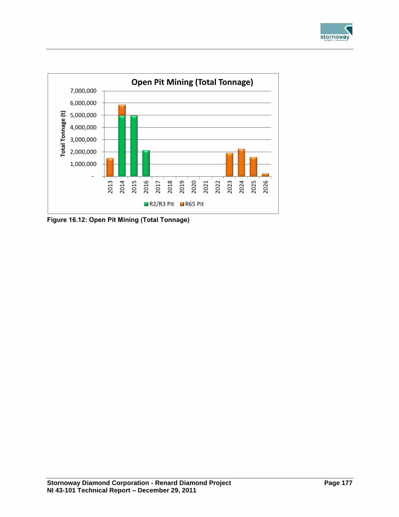
Stornoway Diamond Corporation - Renard Diamond Project Page 177 NI 43-101 Technical Report – December 29, 2011
Figure 16.12: Open Pit Mining (Total Tonnage)
-
1,000,000
2,000,000
3,000,000
4,000,000
5,000,000
6,000,000
7,000,000
20
13
20
14
20
15
20
16
20
17
20
18
20
19
20
20
20
21
20
22
20
23
20
24
20
25
20
26
Tota
l To
nn
age
(t)
Open Pit Mining (Total Tonnage)
R2/R3 Pit R65 Pit

Stornoway Diamond Corporation - Renard Diamond Project Page 178 NI 43-101 Technical Report – December 29, 2011
17.0 RECOVERY METHODS
Process Flow Sheet 17.1.The process flow sheet in Figure 17.1 was developed based on the following key aspects:
The material characteristics observed, and data obtained from the treatment of underground samples from Renard 2, 3 and 4 in Stornoway’s Lagopede bulk sample plant;
Specific unit operation test work;
Conventional diamond processing techniques as successfully employed in Canada;
Liberation effectiveness;
Circuit simplicity;
Cost effectiveness; and
AMEC Americas Limited’s (AMEC) extensive diamond processing experience.
Plant Design 17.2.To minimize footprint and capital costs the diamond process plant design has a single process line for comminution and ore preparation. Capacity considerations dictate that two DMS lines for concentration and three lines for fines dewatering are required. All process equipment including storage bins and materials handling equipment is housed within a heated building, heated transfer towers or heated conveyor galleries. The process plant design capacity is 2,160,000 tpa (dry solids basis). The plant overall utilization is estimated to be 78%, equivalent to an operating time of 6,833 hours per year or 315 tph and 6,000 tpd. The ore processing system liberates concentrates and recovers diamonds from 1 mm to 30 mm. Once the plant has been ramped-up to nameplate capacity AMEC believes that with a high standard of maintenance, plant overall utilization could be increased by about 5%.

Stornoway Diamond Corporation - Renard Diamond Project Page 179 NI 43-101 Technical Report – December 29, 2011
Figure 17.1: Block Process Flowsheet

Stornoway Diamond Corporation - Renard Diamond Project Page 180 NI 43-101 Technical Report – December 29, 2011
Liberation design utilizes three stages of crushing where each crusher operates with a large gap to protect against diamond damage. Primary crushing (both on surface and underground) is performed by a jaw crusher, which reduces the size of Run-of-Mine ore to less than 200 mm. Secondary crushing is performed by a cone crusher to reduce ore to less than 50 mm. A HPGR promoting interparticle crushing is used for tertiary crushing and is the principal diamond liberator generating a product size of 80% smaller than 8 mm. A 3,000 t capacity crushed ore bin decouples the surface primary crusher and the underground hoisting system from the plant. The plant design considers the addition of a future large diamond recovery circuit to recover diamonds between 30 mm and 50 mm with x-ray sorting technology. Ore preparation design utilizes a rotary scrubber and vibrating screen to wash, de-agglomerate HPGR product and size ore for DMS concentration. The majority of the unwanted fines (-1 mm) are separated from ore in this circuit and then are pumped to the rejects disposal circuit. A surge bin with a capacity of 400 tonnes decouples the DMS from the ore preparation circuit. Two 200 t/h DMS circuits concentrate -30 +1 mm feed by separating liberated diamonds and heavy minerals from lighter kimberlite and waste constituent minerals, in a density controlled ferrosilicon medium. The DMS rejects stream is sized into two streams; -30 +6 mm, which is combined with fresh feed reporting to the HPGR and -6 +1 mm, which is mixed with dewatered fines and discarded as dry stackable material to the processed kimberlite containment area. A concentrate surge bin with a capacity of 80 tonnes decouples the recovery plant from the DMS circuits. The recovery plant is capable of processing at a maximum rate of 6.8 t/h. Concentrate fed to the recovery plant is sized, then upgraded, using two stages of x-ray sorting per size fraction. X-ray rejects are fed to grease table scavengers to recover diamonds missed by the x-ray sorters and to audit x-ray sorter performance. Grease table rejects are discarded to the processed kimberlite dry stacking area together with plant fines and coarse rejects. X-ray concentrate is dried and further upgraded using magnetic separation and low throughput x-ray sorters for sizes less than 8 mm. Only a low throughput x-ray sorter is used to upgrade sizes greater than 8 mm. Rejects are recycled to the recovery plant feed. Final diamond recovery is achieved by hand sorting diamonds from waste in secure glove boxes, located within the security controlled and monitored recovery plant. The diamonds will be chemically cleaned before preliminary valuation and export for marketing and sales. Security is a key element of the process plant design given the high value and small volume of the final diamond product. A security management system to detect, deter and reduce the possibility of diamond theft in conjunction with an automated diamond recovery process is part of the design. In the rejects disposal circuit, fines rejects (-1 mm) are separated by cyclones into two sizes, a slimes fraction (-0.25 mm) and a grits fraction (-1 +0.25 mm). The slimes fraction is thickened to recover water for reuse within the plant and recombined with the grits fraction to feed

Stornoway Diamond Corporation - Renard Diamond Project Page 181 NI 43-101 Technical Report – December 29, 2011
dewatering centrifuges to produce dry stackable fines rejects. Fines rejects are mixed with DMS coarse rejects and recovery plant rejects for disposal by truck to the processed kimberlite containment area. The following facilities are included in the plant design:
Main plant modular electrical rooms;
Main plant offices and central control room;
Recovery plant modular electrical room;
Recovery plant offices and control room;
Security offices, access control and search rooms;
Metallurgical laboratory;
Compressor room;
Maintenance shop;
Diamond cleaning room;
Diamond stock room; and
Diamond valuation rooms.
The level of automation within the process plant is appropriate, to minimize operator intervention and to optimize productivity and safety. The process plant building has a fire water ring main supplying wall hydrants and fire water hose station distributed throughout the building. Conveyors running in tubular galleries are protected with automatic wet pipe sprinklers.
Materials Handling 17.3.During the initial mine development phase, a large working ore stockpile will be created close to the surface primary crusher station. Stockpiled ore will be reclaimed by front-end loader and fed to the surface primary crusher station during the first few years of operation. The primary crusher station will be heated in winter for ease of operation and maintenance. As the mine transitions from open pit to underground, ore will be trucked from underground to the working stockpile. Once the shaft hoisting system is available ore will be crushed underground, hoisted to surface and conveyed to a 3,000 t capacity plant feed bin. Because the crushed ore from underground will be wet the conveyor and storage bin on surface will be housed in a heated gallery and building respectively. Conventional belt conveyors will be used to transport plus 1 mm ore and waste within the plant. Conveyors linking the main building and the transfer tower will be housed in tubular galleries, which are insulated and heated. Plant rejects will be dewatered and mixed to produce a stackable waste, which will be trucked from a load-out bin to the processed kimberlite containment area.

Stornoway Diamond Corporation - Renard Diamond Project Page 182 NI 43-101 Technical Report – December 29, 2011
Consumption 17.4.Kimberlite processing to recover diamonds is essentially a mechanical process, with limited use of chemicals/reagents. The estimated consumption of the chemicals/reagents required for a 2.16 million tonnes per year plant is shown in Table 17.1.
Table 17.1: Consumption of Chemicals/Reagents
Chemical/Reagent Consumption
Ferrosilicon 432 tonnes per year
Flocculant 7.6 tonnes per year
Caustic Soda 3 tonnes per year
Hydrochloric Acid 1,825 litres per year
Grease 3,500 litres per year
Degreasing Solvent 4,000 litres per year
Stornoway Diamond Corporation - Renard Diamond Project Page 183 NI 43-101 Technical Report – December 29, 2011
18.0 PROJECT INFRASTRUCTURE
Geotechnical Investigations 18.1.This section provides a summary of the geotechnical investigations performed at the plant, airstrip, landfill, and processed kimberlite containment (PKC) facility sites. Geotechnical investigations were performed in the fall of 2010 at the various project sites to determine the soil and bedrock conditions in order to provide input to infrastructure design and construction. Bedrock surface profiling in the plant site area was also performed using a drill rig. Visual logging and sampling of soil and bedrock was performed during the advancement of boreholes and test pits. Geotechnical testing of select soil samples and bedrock core was performed. Groundwater monitoring wells were installed at selected locations. The following is the summary of the geotechnical investigations:
Plant site: 39 bedrock profiling boreholes, three test pits, and three groundwater monitoring wells;
Airstrip: two boreholes, six test pits, and two groundwater monitoring wells; and
Landfill: two boreholes and two groundwater monitoring wells.
The soil and groundwater conditions discussed herein describe those encountered at the testing locations and at the time of testing; conditions may vary substantially from those encountered. The general stratigraphy of the plant site, airstrip and landfill is topsoil over sand to sand and gravel over till over bedrock. Surficial peat deposits and outcropped bedrock are also present at the sites. The topsoil thickness varied from 0 to about 0.2 m. The compactness condition of the sand to sand and gravel soils ranged from loose to very dense; very dense for that of the till. The depth to bedrock ranged from 1.0 m to 6.8 m at the plant site, 6.8 m to 17.3 m at the airstrip, and 2.8 m to 3.8 m at the landfill at the drilling locations. The measured groundwater levels ranged between 1.3 m to 2.4 m below the ground surface in the wells at the plant site at the time of the geotechnical investigation. No groundwater measurements were possible at the airstrip and landfill due to access limitations during the geotechnical campaign. Subsequent measurements by Stornoway indicated groundwater levels ranged between 2.3 m to 2.7 m below the ground surface in the wells at the landfill site and 1.2 m below ground level at the airstrip. All groundwater monitoring wells are periodically measured by Stornoway. With provision for suitable groundwater control, no conditions of particular concern were encountered during the investigations.
On-site Infrastructure 18.2.This section describes the on-site infrastructure that will be required for the development of the Renard Project. The section discusses the necessary site preparation, water supply requirements, solid and liquid waste disposal, power requirements, fuel storage, service building requirements, communications requirements, airport facilities and explosive handling and storage. The locations of the plant site infrastructure and the accommodation complex are

Stornoway Diamond Corporation - Renard Diamond Project Page 184 NI 43-101 Technical Report – December 29, 2011
shown on Figure 18.1, while a more detailed plant site lay-out is shown on Figure 18.2. The airport, located some 10 kilometres south of the Renard Project is not shown on the figures.
Figure 18.1: Locations of Plant Site Infrastructure and Accommodation Complex
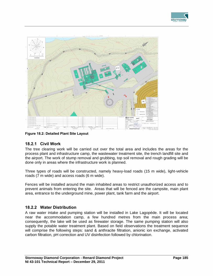
Stornoway Diamond Corporation - Renard Diamond Project Page 185 NI 43-101 Technical Report – December 29, 2011
Figure 18.2: Detailed Plant Site Layout
18.2.1 Civil Work
The tree clearing work will be carried out over the total area and includes the areas for the process plant and infrastructure camp, the wastewater treatment site, the trench landfill site and the airport. The work of stump removal and grubbing, top soil removal and rough grading will be done only in areas where the infrastructure work is planned. Three types of roads will be constructed, namely heavy-load roads (15 m wide), light-vehicle roads (7 m wide) and access roads (6 m wide). Fences will be installed around the main inhabited areas to restrict unauthorized access and to prevent animals from entering the site. Areas that will be fenced are the campsite, main plant area, entrance to the underground mine, power plant, tank farm and the airport.
18.2.2 Water Distribution
A raw water intake and pumping station will be installed in Lake Lagopède. It will be located near the accommodation camp, a few hundred metres from the main process area; consequently, the lake will be used as firewater storage. The same pumping station will also supply the potable water treatment plant. Based on field observations the treatment sequence will comprise the following steps: sand & anthracite filtration, anionic ion exchange, activated carbon filtration, pH correction and UV disinfection followed by chlorination.

Stornoway Diamond Corporation - Renard Diamond Project Page 186 NI 43-101 Technical Report – December 29, 2011
18.2.3 Wastewater Treatment
The effluent from the sewage treatment plant will be discharged into Lac Kaakus Kaanipaahaapisk (Lagopède Lake), downstream of the raw water intake. The effluent standards for the Project will be established according to the characteristics of the receptor area, the loads of the sewage effluent and the uses to protect. The selected treatment system is facultative aerated lagoons, in a series composed of 3 lagoons having an overall retention time of 30 days and a chemical de-phosphating system. A sludge drying bed is planned for the dehydration by freeze-thaw of the sludge which will accumulate in the lagoons.
18.2.4 Solid Waste Management
An outdoor sorting center will be set up for the management of recyclable waste. Containers will be used on the site for recycling. Composting of kitchen waste is not considered for the moment due to the presence of bears in the sector. Separated containers will be used for the storage of hazardous wastes. These containers will be sent to southern Québec for recycling and/or disposal. A trench landfill system with a volume of 25,000 m³ is considered for other solid waste management. This volume takes into account the waste which will be produced during the construction, operation and closing phases, plus the volume of soil to be used for regular covering of the waste. Granular materials will be stockpiled in the vicinity of the landfill such that waste will be covered regularly.
18.2.5 Power Plant and Electrical Distribution
The power plant design will include a heat recovery system, fuel day tanks, exhaust systems, storage cells and chargers, 4.16kV synchronization switchgear and a power management controller. The plant will consist of 12 generators with 10 units running, 1 unit undergoing planned maintenance and 1 unit on standby. The generators will operate at 4.16kV, 3 phases, 60Hz, synchronized together on common switchgear. The rated generator power factor will be 0.8. The generators will be able to absorb the starting peak load of the hoists with a voltage drop of less than 10%. Hoists will be controlled by variable frequency drives. The generators will operate on Arctic-grade diesel fuel. The main power generation plant will feed the medium voltage distribution network at 4.16 kV. This main switchgear will be housed in a main electrical room located near the power generation shelters. An aerial distribution network at 4.16 kV will feed the buildings on the site, and pole-mounted or pad-mounted step-down transformers, as required by the connected loads, will reduce the voltage to 347/600 V, 3 phases, 60 Hz. Uninterruptible power supply (UPS) units will be provided to the accommodation complex, mine office and airport for telecommunication equipment, fire alarm system, security system and closed circuit television (CCTV). Emergency generators will be used to support critical loads during power outages at camp buildings and hoist room.

Stornoway Diamond Corporation - Renard Diamond Project Page 187 NI 43-101 Technical Report – December 29, 2011
18.2.6 Heating
Underground mine air will be heated with heat recovered from the cooling systems of the generators in the power plant. Propane burners will supplement mine air heating. Heat recovered from the generators will be used for the generation of heated water/glycol for air intake heating of underground ventilation system. The main buildings will be heated by the propylene glycol network heated by fuel fired boilers. Two primary glycol networks are needed since the camp complex is far from the power generator facilities. Consequently, the heat recovery from the accommodation camp utility building will be used for the accommodation complex and the power generator facilities will provide for the others. The other buildings will be heated either by electricity or by forced-air furnaces.
18.2.7 Fuel Storage
A tank farm will be constructed to store arctic-grade diesel, unleaded gasoline for light vehicles and propane tanks will be located near usage points. The entire tank farm will be mostly automated and equipped with a communication system and a warning system. In addition to fuels stored on-site at the tank farm there will be a jet-fuel and diesel storage facility at the airport. This facility will include a double-walled tanks which will be equipped with integrated loading/unloading pumping systems.
18.2.8 Service Buildings
The camp complex and airport terminal will be wooden structural modular buildings. They will be factory built and assembled at site. The cold storage and the primary crusher enclosure will be fabric-covered buildings consisting of a light structural steel frame covered by PVC/polyester membrane. All other buildings will be either self-supporting, pre-engineered steel buildings or conventional pre-engineered steel buildings. In either case the envelope will be prefabricated at the factory and installed on site. Air conditioning will be installed in the cafeteria, the leisure building and the office building. First line fire protection will be by portable ABC type extinguishers installed in all buildings. The cafeteria, the truck shop, the office building, the power plant generator building and the process plant and conveyor galleries will also be completely protected by a system of automatic water sprinklers. An aqueous film forming foam (AFFF) fire suppression system is required for the tank farm.. The confinement dyke under and around the tanks will be compartmentalized to reduce the quantity of foam required. If a fire occurs, the trailer for the production of foam will be transported to the site of the fire by the fire truck. Two fire hydrants will be located around the tank farm to supply the fire truck and foam trailer with water.

Stornoway Diamond Corporation - Renard Diamond Project Page 188 NI 43-101 Technical Report – December 29, 2011
Accommodation Complex The accommodation complex will house the reception area, which will also serve as the main gate to the site, the service area for the cafeteria, dormitories, one leisure building, a utility building and a garage for emergency vehicles. The complex will be made of wooden structural modular buildings except for the leisure building, the utility building and the garage for emergency vehicles which will be self-supporting pre-engineered steel buildings. An access ramp will be provided for physically challenged personnel to access the camp reception area, first floor of dormitories, leisure modular building, and service building. Camp Reception Complex This building will be the main entrance to the site. It will serve for security control and as the camp reception area. The security control area will consist of offices, a reception desk for ground traffic, and a security control room including an x-ray scanner for luggage, metal detector for personnel and search rooms for passengers travelling by aircraft. The camp reception area will consist of offices, a reception desk to register and direct people, and a closed room for lockers to store the belongings of workers in transit. Dormitories The dormitories will consist of individual furnished rooms. Each room will be equipped with a bed and night table, a desk and a chair, a closet, a bathroom with shower, a commode and a sink. Each room will also have an IP phone, an internet connection and a TV. Two types of rooms will be provided: those with private bathrooms and those with a shared bathroom between two rooms. The complex will provide 60 private rooms and 168 semi-private rooms. Emergency Vehicle Garage This heated building will house the fire truck and ambulance. Service Building The service building will provide the area for food service with a seating capacity of 224 people. The service will be cafeteria style with a self-service area. It will be equipped for food preparation, washing, all required storage and a reception area. The cafeteria will be ventilated and air conditioned by a variable volume system. A make-up air system will be provided to compensate for the kitchen exhaust hoods. An insulated and refrigerated room will be provided for garbage storage. Leisure Building The leisure building will be fully equipped for physical training activities (weight lifting equipment, stationary bicycles, etc.) and leisure activities (billiards and cards tables, fireplace, television room, cinema, and a veranda). Utility Building This building will house the heating and hot water production equipment for the camp complex.

Stornoway Diamond Corporation - Renard Diamond Project Page 189 NI 43-101 Technical Report – December 29, 2011
Heavy Vehicle Truck Shop, Light Vehicle Garage and Workshop This single building will be used for maintenance of heavy and light vehicles (HV and LV). The building will also include a wash bay, welding shop, instrument shop, electrical shop, mechanical maintenance shop. Space over the LV garage and shops will be used as office area which will include the server room and control room for site infrastructure. Warehouse A single storey warehouse with racking is joined to the HV truck shop, LV garage and workshops. Office Building The office building will consist of two stories. The ground floor will house the mine rescue area, the infirmary, a training room, a laundry room, the women’s locker room, the men’s locker room, a prevention office, the lamp room and the foremen area. The second floor will contain the reception area, offices, the training room, the photocopy and paper room, a meeting room, a lunch area, the computer room, two storage rooms, the telecommunication room and heating room.
18.2.9 Technical Facilities
The following buildings will be constructed as technical facilities: Core Shack This building will be used to log and analyse core samples. A separate storage area will be available for core storage. Boiler Area This building will house the equipment for heating and hot water production for the site except the camp complex which will have independent equipment. The primary glycol heating network of the site comes from this boiler room and includes the two oil fired packaged boilers, pumps, expansion reservoir, and a high pressure glycol unit. Raw Water Intake This small building will house the pumps. Potable Water Treatment This building will house the water treatment equipment, pumps and a small office. Wastewater Treatment This building will house the equipment needed for the wastewater treatment. A small office with a laboratory is also integrated into this building.
18.2.10 Telecommunications
A single satellite dish antenna with dual low-noise block-down converters (LNB’s) block-up converters (BUC’s), modems and related equipment will be provided at the mine site for

Stornoway Diamond Corporation - Renard Diamond Project Page 190 NI 43-101 Technical Report – December 29, 2011
telephone and data transmission. Access to the link will be through separate VLAN’s for the administrative and recreational use. The airport communication systems will be serviced from the mine site by way of a fiber optic cable link. This will afford surveillance of the remote airport site while it is unmanned. The satellite TV and radio system will be designed to receive and broadcast 12 commercial channels selected by the client. In addition, equipment will be provided to allow local DVD’s and CD’s to be broadcast. IP Telephone service will be installed at all site locations where warranted for operation and/or emergency communications needs. The industrial areas of the site (mill, power plant, garages etc.) will be equipped with more robust telephone sets and cabling, where warranted. The CCTV and access control system will provide coverage of the exterior of the mine complex, the accommodation complex and the airport complex. The Access Control System will include gates and card readers for site access of these three complexes. In addition, since the airport is located at a considerable distance from the main site, CCTV coverage is required to maintain site monitoring at all times.
18.2.11 Access Control
All vehicles accessing the site via the main road have to pass through the main gate located at the accommodation complex. All access checks will be conducted at this location. Once access is permitted, vehicles can move freely (under CCTV monitoring) in both complexes (accommodation and process complexes). The other access gates will only be equipped with a camera and a proximity sensor to allow automatic opening of the portal. Like the accommodation complex main gate, the airport gate allowing access to the apron will be equipped with a card reader, an intercom and a fixed camera. Security gates will be installed not only to restrict access for vehicles, but also to block the movement of animals, such as bears, that might be present in the area. To do this, a rising fenced barrier will be installed. The main monitoring station will be installed in the video surveillance office at the camp reception complex building. This station will monitor the main site and the airport.
18.2.12 Airport
The airport for the Renard Project will be owned and operated by Stornoway with chartered aircraft for its exclusive needs. An agreement will be made with the security services of that airport for the passengers and their baggage to be verified at the departure of flights to the Renard airport. The airport will not be certified by Transport Canada. The reference aircraft for the design of the runway is the DASH 8, Series 300 with a capacity of 50 passengers. A gravel surface is proposed for the runway, taxiway and apron areas. The airport will be equipped to support night operations and will be equipped with visual navigational aids and lighting.

Stornoway Diamond Corporation - Renard Diamond Project Page 191 NI 43-101 Technical Report – December 29, 2011
The jet fuel tank will be on the east side of the apron. A 500 gallon reservoir of de-icing liquid will be housed in a shed, and equipped with a heating element. A pre-fabricated wooden structural modular building will serve as a terminal. It will include an office with suitable visibility for Unicom the airport operator, one (1) caretaker’s storage room and one (1) washroom. No personnel and baggage security screening will be installed in the terminal building. The screening and search of personnel will be done at the accommodation complex. Waiting areas will thus be at the accommodation complex, and no waiting room will be provided at the terminal. A self-supporting pre-engineered steel clad structure building will be the maintenance garage for the storage of materials and the wheeled equipment used for the summer runway maintenance and winter snow clearing activities. All maintenance of equipment will be performed at the mine site truck shop. A water well will be bored to supply water to the terminal building and maintenance garage. Bottled water will be used for drinking water. Wastewater will be treated by a septic installation, appropriately located with respect to the water supply well.
18.2.13 Explosive Storage and Handling Area
Bulk emulsion will be stored on the emulsion site under federal regulations. Packaged explosives will be stored on the explosive site under provincial regulations. The emulsion ISO container will be built to be heated with electricity when the outside temperature is too low and emulsion risks becoming too viscous. From this container, emulsion will be pumped into an emulsion truck for open-pit blasting or into 1500 kg bins for underground operations. The wash bay garage is used to park and wash the emulsion truck. The explosive storage site will consist of one (1) heated and lit explosive magazine and one (1) detonator magazine with a capacity of 100,000 detonators.
Off-Site Infrastructure 18.3.18.3.1 Route 167 Extension
Land access to the Renard Project will be via the extension of provincial Road 167. This work will be carried out by the Ministère des Transports du Québec (MTQ). The entire Route 167 Extension Project, from studies through to permitting and execution, is under the responsibility of the MTQ. This road will afford a year round access linking the Project to the municipalities of Mistissini and Chibougamau. The road will be constructed to MTQ standards with a gravel surface and a design speed limit of 70 km/h.

Stornoway Diamond Corporation - Renard Diamond Project Page 192 NI 43-101 Technical Report – December 29, 2011
The Route 167 Extension Project is a key component of the Government of Québec’s recently announced Plan Nord and it will be a key component of regional development. Road 167 currently terminates at Temiscamie and a winter road approximately 140 km in length extends from this location to the decommissioned Eastmain mine. Strateco Ressources Inc (Strateco) currently operates this winter road, with a trunk road extending from the main winter road to their project site. The project was subdivided into 4 plots of construction (A, B, C & D)
MTQ’S schedule currently anticipates the following milestones for road construction:
Construction start is planned with the construction of plots A for Q4 2011;
Permanent, rough terrain, access to the Renard site is planned for Q3 2013; and
Completion of the road construction is planned for Q3 2015.
The environment public hearings for the Route 167 Extension Project were conducted on August 31, 2011. The decree authorizing the road project was remitted in December 2011 therefore the construction work can begin. Agreements have been ratified with the Government of Québec to establish Stornoway’s contribution to capital and operational expenses for the road. These agreements are conditional on the completion of the road construction, the regulatory approval of the Renard Project and the financing of the Renard Project. The agreements include cost sharing provisions to accommodate other anticipated users of the road, benefitting Stornoway should other users participate. Figure 18.3 shows the proposed road alignment.

Stornoway Diamond Corporation - Renard Diamond Project Page 193 NI 43-101 Technical Report – December 29, 2011
Figure 18.3: Road 167 Extension (Reproduced with permission from MTQ)

Stornoway Diamond Corporation - Renard Diamond Project Page 194 NI 43-101 Technical Report – December 29, 2011
Processed Kimberlite Containment Facility 18.4.This section provides a summary of the geochemical classification of the kimberlite, processed kimberlite (PK) and waste rock, site selection of the processed kimberlite containment (PKC) facility, and the design of the PKC facility.
18.4.1 Site Selection
A site selection study was performed to determine the location of PKC facility. The PKC facility was sized to provide sufficient storage capacity in a single location for all size fractions of the PK to be generated during the mining operations proposed in this report. Five candidate sites were initially identified for evaluation using economic, social, and economic indicators. The candidate sites are shown on Figure 18.4.
Figure 18.4: Candidate Sites for Processed Kimberlite Containment Facility
Each candidate site was visually inspected by a helicopter fly-over and a walk-through. The observations made during the site visit allowed confirmation that the topographic mapping of the candidate sites generally matched the field conditions. The preliminary facility layout for each candidate site was confirmed to be possible based on the observations made. The site comparison and the final selection were accomplished with a decision support tool, GoldSET, which evaluated nearly 50 criteria, or indicators, grouped under environmental, social, and economic dimensions in accordance with pre-determined scoring schemes. It is important to note that the potential locations for the PKC facility are compared relative to each other; namely, the selected site is the “best” of those considered in the study.

Stornoway Diamond Corporation - Renard Diamond Project Page 195 NI 43-101 Technical Report – December 29, 2011
The scoring scheme of each indicator is either quantitative or qualitative. Quantitative indicators are those with measurable quantities with a determined unit, for example length in metres. The indicator is progressive when an increase of the value corresponds to a favourable situation or regressive when a decrease of the value corresponds to a favourable situation. In order to proceed with the evaluation of the quantitative indicators, all values are normalized on a scale of 0 to 100. The best option receives a score of 100, while the worst option receives 0. The results of intermediate options are calculated in accordance with a linear function. In the case of the qualitative indicators, the scoring scheme is based from 0 to 100. While the scoring scheme is set in advance and does not change from one project to another, the weighting of each indicator must be uniquely set for each project. The weighting is an evaluation of the relative weight between indicators in a specific dimension (environmental, social and economic) and the value varies between 1 and 3. The weighting is based on the importance of the indicator for the organization, the interest of the stakeholders for that same indicator along with the level of influence of the stakeholders. Based on the results of the evaluation, Site E was determined to be the optimal location and is shown on Figure 18.5.
Figure 18.5: Selected Location (Site E) for Processed Kimberlite Containment Facility

Stornoway Diamond Corporation - Renard Diamond Project Page 196 NI 43-101 Technical Report – December 29, 2011
18.4.2 Facility Design
The design of the PKC facility is based on the results of the geochemical classification of the PK (refer to Section 20.2) and those of the site selection (refer to Section 18.4.1). The development basis for the design is such that the PKC facility may be readily expanded from the scenario considered in this report, namely, the mining of all mineral reserves identified, to the mining of all mineral resources presented in this report. Dewatering of the PK at the process plant was evaluated as part of the global assessment of the risk to the Project. The dewatering of the PK at the process plant by means of centrifuging was identified as the preferred option from environmental and economic points-of-view. The dewatering of the PK at the process plant enables the development of the PKC facility as a dry stack. The three fractions of the PK will be mixed at the process plant and trucked to the PKC facility. This significantly reduces risk relative to a conventional slurry-type facility for facility development, operation, and management as no water is pumped to the facility. Progressive closure is a key element of the facility development and is facilitated by the dry stack basis. Water management of runoff and seepage from the facility is collected by a series of perimeter ditches and sumps for treatment, as required, prior to release to the environment. The design objective for the PKC facility is that the facility must be capable of receiving all materials that may potentially be produced during mining operations. The meeting of this objective is paramount such that mining and/or processing operations are not shutdown as a result of the PKC facility development. The facility will be developed to promote progressive closure and provide stability over both the short-term and the long-term and without impacting fish habitat or bodies of water. Slope stability (both static and seismic conditions), wind erosion, and water erosion will be provided into the post-closure period through the development of the facility during operations. The PKC facility will be unlined based on the results of the geochemical classification of the PK (refer to Section 20.2) and the estimated seepage rate from the facility. The facility will be developed, for the most part, using the PK generated during operations. A closure cover comprising appropriately-sized rockfill and vegetated overburden will be progressively placed during the development of the facility. The PKC facility is designed in recognition of several project, site, and environmental objectives. The objectives are that:
The PKC facility provide adequate storage capacity for the anticipated quantity of PK to be produced;
The entire life of mine storage is to be contained entirely within the footprint allotted for the PKC facility;
That the PKC design may be readily expanded to encompass all currently identified mineral resources of the Renard Project;
The design reduces the potential impact on the local groundwater;
The design promotes the progressive closure of the facility;
The design avoids potential impact on local fish habitat; and

Stornoway Diamond Corporation - Renard Diamond Project Page 197 NI 43-101 Technical Report – December 29, 2011
The contact water will be collected for appropriate treatment prior to release into the environment. This will be achieved through a series of perimeter ditches and sumps that will route and collect runoff and seepage from the facility for subsequent treatment, if required.
The PKC facility at the completion of the BFS scenario is shown Figure 18.6.
Figure 18.6: Processed Kimberlite Containment Facility - Completed BFS Facility
Construction, development, and progressive closure of the PKC facility, including activities such as foundation preparation, placement of engineered fill, placement of the closure cover and haul road construction being performed during non-freezing periods will be carried out continuously over the life of the facility. Geotechnical instrumentation, comprising piezometers, thermistors, and survey monuments, will be installed and monitored through operations, closure, and into post-closure periods. The instrumentation will enable monitoring and assessment of the performance of the facility and to verify design assumptions.

Stornoway Diamond Corporation - Renard Diamond Project Page 198 NI 43-101 Technical Report – December 29, 2011
Waste Rock, Ore & Overburden Piles 18.5.Overburden, waste rock and kimberlite ore will be stored in three separate piles. The specifications for these piles are presented in Table 18.1 and Figure 18.7. The overburden pile is sized to include the overburden material mined from the Renard 2/Renard 3 pit and the overburden mined from the Renard 65 borrow pit. The total overburden to be stored is 2.9 Mt, or 1.8 million loose cubic metres since some overburden will be used to surface slopes of the PKC facility. The overburden pile will be constructed in 5 metre lifts and will be 20 metres in height. The slopes of the overburden pile will be armoured with rip-rap material to increase slope stability.
Table 18.1: Pile Specifications
Pile Specifications Overburden Pile Waste Rock Dump Ore Stockpile
Lift height (m) 5 5 5
Lift offset or catch bench (m) 5 8.37 5
Pile face angle (deg) 26.6 37 37
Overall slope angle (deg) 18.4 (3H:1V) 18.4 (3H:1V) 23.3
Pile height (m) 20 52 10
Elevation of pile surface (m) 535 570 530
Footprint surface area (ha) 13.1 20.7 7.6
Volume of pile (M m3) 1.8 3.7 0.41

Stornoway Diamond Corporation - Renard Diamond Project Page 199 NI 43-101 Technical Report – December 29, 2011
Figure 18.7: General Arrangement of Open Pits and Piles

Stornoway Diamond Corporation - Renard Diamond Project Page 200 NI 43-101 Technical Report – December 29, 2011
The waste rock dump is sized to contain waste rock mined from the Renard 2/Renard 3 pit and some waste rock mined from the Renard 65 phase 1 borrow pit. The total waste rock pile at the end of June 2017 is 7.8 Mt. An estimated 2.3 Mt of waste rock will be used for various construction purposes over the Project life. The waste will be re-handled and used as backfill into the Renard 2/Renard 3 pit, once the underground operation breaks through into the pit bottom, and into the Renard 4 mine through backfill raises. The Renard 65 phase 2 borrow pit will be mined to supply waste rock for backfilling once the waste dump has been completely exhausted. The ore stockpile base will be built from a combination of waste rock and kimberlite from the Renard 65 phase 1 borrow pit. Building the ore stockpile base from low grade kimberlite material will prevent unnecessary dilution when the ore stockpile is re-handled and sent for processing. The base will be constructed with approximately 580,000 m3 of rock fill and is designed to accommodate approximately one million tonnes of ore.

Stornoway Diamond Corporation - Renard Diamond Project Page 201 NI 43-101 Technical Report – December 29, 2011
19.0 MARKET STUDIES AND CONTRACTS
Diamond Pricing and Market Studies 19.1.19.1.1 Diamond Supply Forecasting
In most diamond supply and demand forecasts, future rough diamond supply is assessed on the basis of current and future production plans at the major producing mines. These supply projections are generally robust, as most of the world’s major diamond mines are operating on a steady-state basis or transitioning to lower production rates as they age, and it typically takes between 8 and 12 years to find and develop a new diamond mine. WWW International Diamond Consultants (WWW) forecast a 21% increase in world diamond production on a volume basis between 2011 (when mine production is expected to have recovered to production cut-backs made during 2008-2009) and 2020, and a 6% increase in value terms using fixed September 2011 rough prices (WWW, 2011)., Alrosa Company Ltd also predict a 21% increase in carat production over the same period, with a 4% decrease in production from existing mines being offset by modest levels of new production (Alrosa, 2011).
19.1.2 Diamond Demand Forecasting
Diamond demand forecasting (expressed as either demand for rough diamonds in the cutting centers or demand for polished diamonds for diamond jewelry manufacture) is a more complex calculation based on, amongst other things:
Long term Gross Domestic Pproduct (GDP) growth forecasts in the main consumer markets;
Diamond jewelry consumer growth trends in developing markets; and
Short term inventory draw-down or re-stocking trends within the diamond pipeline, often linked to levels of bank debt.
The principal difference between published diamond demand forecasts is whether they are based purely on the first of these elements solely and assume steady state diamond demand linked to GDP growth or whether they also take into account the second and third of these elements, and allow for market changes outside of GDP growth and short term inventory factors. All current diamond demand forecasts are strongly leveraged to International Monetary Fund-based GDP growth forecasting in India and China. Uncertainty exists on the current size of the Chinese and Indian markets, and their future growth rates. However, should the current growth rates in diamond jewelry consumption in China and India of between 10% and 15% be sustained, by 2020 these markets will exceed the size of the US market, which is expected to grow at a lower rate. Diamond jewelry growth is forecast to increase by 77% in nominal value between 2011 and 2020 (WWW, 2011). Without a commensurate increase in rough diamond supply, this must inevitably lead to an increase in diamond prices and a decrease in the relative quality of diamonds within a piece of diamond jewelry.

Stornoway Diamond Corporation - Renard Diamond Project Page 202 NI 43-101 Technical Report – December 29, 2011
19.1.3 May 2011 Diamond Valuation Exercise
During the period of May 9th to May 13th, 2011, parcels of diamonds recovered from the Renard 2, 3 and 4 kimberlite pipes during the 2007 bulk sampling program (the “Valuation Samples”) were presented for a valuation in Antwerp, Belgium under the supervision of WWW. The results of the valuation exercise are summarized in Table 19.1. In addition to performing its own valuation, WWW showed the diamond samples to four other experienced rough diamond companies in order to obtain additional market based valuations (an “open market” valuation). For each Valuation Sample, the average of the five valuations was used by WWW to construct a diamond price model with “High” and “Minimum” sensitivities. Diamond price models represent the true diamond price that might reasonably be expected for a kimberlite ore body based on standard commercial-scale recoveries of all diamond size classes. They differ from the achieved diamond valuation price principally through a correction which is applied for the absence of large diamonds which are typically under-represented in exploration scale samples. WWW recommended the adoption of a single diamond price model for the Renard 2 and Renard 3 ore body valuation samples given the similarity of the diamonds in terms of diamond qualities and size distribution. The Renard 2 and Renard 3 base case price model is US$182/carat. A separate diamond price model was adopted for the Renard 4 valuation sample given its apparently finer distribution of diamond sizes. The Renard 4 base case price model is US$112/carat.

Stornoway Diamond Corporation - Renard Diamond Project Page 203 NI 43-101 Technical Report – December 29, 2011
Table 19.1: May 2011 Diamond Valuation Results
Body
Valuation
Sample
(carats)
Achieved Prices1 for the Valuation Samples WWW Price Modeling
Number of
Independent
Valuations
Average of
Independent
Valuations
(US$/carat)
Minimum of
Independent
Valuations
(US$/carat)
Maximum of
Independent
Valuations
(US$/carat)
WWW
Valuation
(US$/carat)
WWW
Base Case
Model
(US$/carat)
WWW
"High"
Model
(US$/carat)
WWW
"Minimum"
Model
(US$/carat)
Renard 2 1,580 5 $173 $143 $195 $195 $182 $236 $163
Renard 3 2,7532 5 $171 $137 $195 $190 $182 $205 $153
Renard 4 2,674 5 $100 $87 $107 $107 $112 $185 $105
1 All Price Estimates Based on a +1 DTC sieve size cut-off
2 Includes 105 carats from Renard 3 sample 3105 not previously available for valuation

Stornoway Diamond Corporation - Renard Diamond Project Page 204 NI 43-101 Technical Report – December 29, 2011
19.1.4 Review of Diamond Size Frequency Distributions
In previously published NI 43-101 Technical Reports ((Farrow, D. 2010) and (Farrow, D. and Farrow, D.J., 2011) a description has been given of successive studies into the apparent similarities, and dissimilarities, in diamond size frequency distribution exhibited by the Renard diamond bulk samples. All previous studies and diamond valuation exercises have noted the similarity in size distribution and diamond quality between the Renard 2 and Renard 3 diamond samples, both between each kimberlite pipe as a whole and between each pipe’s individual lithological units. In modelling the base case diamond price estimate for the Renard 2 and Renard 3 kimberlite pipes, a single size frequency model, based on the combination of the Renard 2 and Renard 3 Valuation Samples, has been adopted by WWW in the May 2011 valuation exercise. In contrast to the similar diamond size frequency distributions of Renard 2 and Renard 3, the Valuation Sample collected from Renard 4 has a lower incidence of large diamonds and produces an apparently “finer” diamond size frequency distribution. In the valuation exercise of May 2011, WWW derive a lower base case diamond price model for the Renard 4 sample based primarily, but not exclusively, on a finer size frequency model for Renard 4. A review of the of the Renard 4 diamond bulk sample process was undertaken in December 2009 (Volume II, “Analysis of Renard 4 Bulk Sample SFD and its implication for Diamond Price Assumptions”, Stornoway Diamond Corporation, December 23, 2009) to attempt to explain the anomalous size frequency distribution of the Renard 4 Valuation Sample compared to the other bulk samples from the Project. The review addressed:
Comparative size frequency distributions of the diamond sample data;
Comparative diamond breakage analysis of the diamond sample data;
Analysis of process plant performance for each sample and its potential impact on diamond sample recoveries; and
Comparative diamond quality assortments of the Renard bulk samples.
The review confirmed that the diamonds in the bulk samples from Renard 2, 3 and 4 show a large degree of similarity in their size frequency distributions, particularly when using a cumulative stone probability or normalized grade per unit analysis. An internal analysis of comparative quality assortment data confirmed little difference in diamond assortment and value per size class between the Renard 2, 3 and 4 bulk samples. Deviations in the cumulative carat probability plot for the Renard 4 sample, from which a valuation model is derived, can be attributed to grade loss through diamond breakage or stone loss in the DTC sieve classes greater than 3GR in size. An independent analysis of diamond breakage in each diamond bulk sample, conducted by Dr. Paddy Lawless, an independent consultant, between August and September 2009, confirmed that there is an anomalous level of diamond breakage in the Renard 4 bulk sample compared to the Renard 2 and Renard 3 bulk samples. The relative proportions of this breakage, when quantified in terms of grade loss, are consistent with that implied by the size frequency distribution analysis. The Renard bulk samples were processed at the 10 tonne per hour dense media separation plant located at the Project site, and process

Stornoway Diamond Corporation - Renard Diamond Project Page 205 NI 43-101 Technical Report – December 29, 2011
plant records confirm issues of concern with the processing of several Renard 4 bulk sample rounds that might have led to both diamond loss and diamond breakage. Consequently, Golder (2010) concluded that the size frequency distributions of Renard 2, Renard 3 and Renard 4 are similar, and that it is appropriate to use a single size frequency distribution to determine value on the basis that there exists a single diamond population within the three kimberlite pipes. This approach was also adopted in the GeoStrat February 3, 2011 NI 43-101 Technical Report when the Mineral Resource statement was further updated. Consistent with this approach, a base case price model of $164/carat for Renard 4 is derived through the application of the May 2011 WWW valuation price data for the Renard 4 Valuation Sample to the Renard 2-Renard 3 size frequency model.
19.1.5 Diamond Price Model Sensitivities and Diamond Price Assumptions
In establishing their diamond price models, WWW determine High and Minimum sensitivities on the base case diamond price based on alternate interpretations of diamond quality and potential value. The choice of “Minimum” and “High” to describe the sensitivity limits is deliberate: in WWW’s view it is highly unlikely that an actual diamond price achieved for each kimberlite ore body upon production would fall below the “Minimum” sensitivity, but it is possible that the actual diamond price achieved may be higher than the “High” sensitivity, which is not a maximum price. For the May 2011 exercise, WWW also incorporated two contrasting interpretations of each sample’s potential diamond size frequency distribution in establishing the High and Minimum sensitivities. For each of Renard 2, 3 and 4, the alternate scenarios are: Each kimberlite pipe has the same diamond size frequency distribution, represented by the sum of the Renard 2 and Renard 3 Valuation Samples (the “Common Size Distribution Scenario” and “Base Case assumption”). Each kimberlite pipe has a different size frequency distribution represented accurately by each kimberlite pipe’s individual Valuation Sample (the “Individual Size Distribution Scenario”) The combination of alternate quality and size distribution interpretations for each Valuation Sample give rise to sensitivities of US$163 to US$236/carat for Renard 2, US$153 to US$205/carat for Renard 3 and US$105 to US$185/carat for Renard 4. As recommended by WWW, Stornoway has adopted a base case diamond price model of US$182/carat for the Renard 2 and 3 kimberlite pipes. Consistent with the prior NI 43-101 Technical Reports, Stornoway has adopted a base case diamond price model of US$164/carat for the Renard 4 kimberlite pipe based on the interpretation of similarity between the Renard 2, Renard 3, and Renard 4, diamond size frequency distributions. The financial analysis includes a sensitivity which estimates the effect of this assumption compared to the alternative interpretation.

Stornoway Diamond Corporation - Renard Diamond Project Page 206 NI 43-101 Technical Report – December 29, 2011
Contracts 19.2.Agreements have been executed with the Government of Québec for the construction and operation of Road 167, which will grant access to the Project site when completed. Agreements have been signed with the Government of Québec to establish Stornoway Diamond Corporation’s contribution. These agreements are conditional on the completion of the road construction, the regulatory approval of the Renard Project and the financing of the Renard Project.
19.2.1 Road Sharing - Capital and Operating Costs
Capital Costs Capital costs for the execution of the Route 167 extension will be borne entirely by the Ministère des Transports (MTQ). A cost-sharing formula has been developed by the MTQ so that users of the highway participate in the construction and maintenance costs associated with the highway. Stornoway will use 243 km of Route 167 to support its operations and its share of the capital and operating costs will be calculated on that basis. The total capital costs for Stornoway will be distributed into payments made over a period of 10 years, starting in 2015, and financed through the Government of Québec. Upon expiration of this agreement in 2025, a new agreement may be negotiated. Should the total contribution of private road users exceed 50% of the initial construction costs, the agreement will provide a mechanism whereby a credit will be granted to Stornoway in the agreements renewed after 2025. Stornoway may elect to pay off the balance of the loan at any time without any penalties. Stornoway’s $44 million contribution to the cost of the extension of Route 167 is payable with interest from July 1, 2015, with the first payment due on December 31, 2015. Payments are made annually for the next 9 years with the final instalment of interest and principal payable on June 30, 2025. Operating Costs Operating costs for the road will comprise expenses such as winter snow clearing and application of abrasives, yearly repairs and maintenance, major periodic infrastructure restoration, etc. Costs will be shared by private users of the road as a function of the length of the road segment used by each private user. The initial road operation cost sharing agreement between Stornoway and the MTQ will be for a period of ten (10) years. As long as Stornoway is the sole private user of the road, Stornoway’s road usage length will be taken as 243 km for the calculation of road maintenance costs. Stornoway’s usage length will be reviewed from time to time as other private users manifest themselves. The payment of operating expenses will be remunerated on a monthly basis by Stornoway to the MTQ. Stornoway will make contributions towards the maintenance of the Route 167 extension in the amount of $1,215,000/year as established with the MTQ for a period of 10 years starting in July 2015 and ending in June 2025. This cost is not subject to escalation and the cost from July 2015 to December 2015 is capitalized.
Stornoway Diamond Corporation - Renard Diamond Project Page 207 NI 43-101 Technical Report – December 29, 2011
20.0 ENVIRONMENTAL STUDIES, PERMITTING AND SOCIAL OR COMMUNITY IMPACT
Roche ltée, Groupe-Conseil (Roche) was mandated to carry out an Environmental Baseline Study (EBS) and an Environmental and Social Impact Assessment (ESIA) for the Renard Project. The EBS and ESIA studies were scoped to comply with the directives issued by Ministère du Développement durable, de l’Environnement et des Parcs (MDDEP) and Comité d'évaluation (COMEV). As of the Effective Date, the EBS and the ESIA reports are pending publication. The EBS includes information on the physical, biological and human environment of the Project study area (127 km²). This information was collected from various sources including data available in the literature (scientific literature, technical reports, government data, ESIAs and EBS conducted in the region), site specific surveys conducted in the Project study area (2003-2011), traditional ecological knowledge from Cree land users through their participation in the surveys, and information provided as part of the Environmental Exchange Groups and other meetings with land users. The following section provides a summary of the reports while Table 20.1 lists the various baseline studies conducted on the property since 2002. The ongoing ESIA process is based on the most up-to-date and detailed information available on the physical, biological and human environment and on the project description. Collaboration between the ESIA team and Engineering resulted in a project design that prevented and minimized environmental (mainly fish habitat) and social impacts and risks, and developed specific mitigation and compensation measures to address those impacts and risks. The design also addresses the management of any residual impacts through an environmental management plan that includes environmental monitoring and surveillance. Environmental and social residual risks to the Project schedule or implementation were identified and addressed as part of the Feasibility Study in a risk register. They are discussed in Section 24.4. To date there are no identified environmental issues that could significantly impact Stornoway’s ability to exploit the planned diamond mine on the Foxtrot Property.

Stornoway Diamond Corporation - Renard Diamond Project Page 208 NI 43-101 Technical Report – December 29, 2011
Table 20.1: Baseline Studies Completed at Renard Project
Year Study Reference
Biological Environment
Ichthyofauna
2003 Environmental Baseline Study Roche. 2003. Environmental Baseline Study – Foxtrot Property. Report prepared for Ashton Mining of Canada Inc.
2005 Environmental Baseline Study Roche. 2005a. Environmental Baseline Study (2004) – Foxtrot Property. Report prepared for Ashton Mining of Canada Inc. 44 pages + 12 annexes.
2009 Fish habitat assessment Stantec. 2009. Fish Habitat Assessment - Renard Mine Property. Report prepared for Stornoway Diamonds Canada Inc.
2010 Environmental and social impact assessment
Roche – SNC-Lavalin. 2010. Étude d’impact sur l’environnement et le milieu social du prolongement de la route 167 Nord vers les monts Otish. Préparé pour le Ministère des Transports du Québec. 404 pages + 2 annexes.
2011 Environmental Baseline Study Roche. 2011. Renard Project. Environmental Baseline Study. Report presented to Stornoway Diamonds Corporation Inc.
Vegetation
2003 Environmental Baseline Study Roche. 2003. Environmental Baseline Study – Foxtrot Property. Report prepared for Ashton Mining of Canada Inc.
2005 Environmental Baseline Study Roche. 2005a. Environmental Baseline Study (2004) – Foxtrot Property. Report prepared for Ashton Mining of Canada Inc. 44 pages + 12 annexes.
2011 Environmental Baseline Study Roche. 2011. Renard Project. Environmental Baseline Study. Report presented to Stornoway Diamonds Corporation Inc.
Benthos
2011 Environmental Baseline Study Roche. 2011. Renard Project. Environmental Baseline Study. Report presented to Stornoway Diamonds Corporation Inc.
Herpetofauna (Amphibians and Reptiles)
2011 Environmental Baseline Study Roche. 2011. Renard Project. Environmental Baseline Study. Report presented to Stornoway Diamonds Corporation Inc.
Avifauna
2005 Environmental Baseline Study Roche. 2005a. Environmental Baseline Study (2004) – Foxtrot Property. Report prepared for Ashton Mining of Canada Inc. 44 pages + 12 annexes.
2011 Environmental Baseline Study Roche. 2011. Renard Project. Environmental Baseline Study. Report presented to Stornoway Diamonds Corporation Inc.
Mammals
2005 Environmental Baseline Study Roche. 2005a. Environmental Baseline Study (2004) – Foxtrot Property. Préparée pour Ashton Mining of Canada Inc. 44 pages + 12 annexes.
2010 Consultations with Tallymen Lussier, C. 2010a. Stornoway diamond corporation Inc. Renard Project. Consultations with land users of trapline M11. Preliminary report. Presented to ROCHE ltée. 11 pages + maps.

Stornoway Diamond Corporation - Renard Diamond Project Page 209 NI 43-101 Technical Report – December 29, 2011
2010 Environmental and social impact assessment
Roche – SNC-Lavalin. 2010. Étude d’impact sur l’environnement et le milieu social du prolongement de la route 167 Nord vers les monts Otish. Préparé pour le Ministère des Transports du Québec. 404 pages + 2 annexes.
2011 Environmental Baseline Study Roche. 2011. Renard Project. Environmental Baseline Study. Report presented to Stornoway Diamonds Corporation Inc.
Physical Environment
Surface deposits
2002 Desktop study Amyot, G. 2002. Programme de caractérisation environnementale préliminaire – Projet d’exploration Propriété Foxtrot. SOQUEM Inc. Ashton Mining Canada.
2003 Environmental Baseline Study Roche. 2003. Environmental Baseline Study– Foxtrot Property. Report prepared for Ashton Mining of Canada Inc. 46 pages + 10 annexes.
2006 Hydrogeological and Geotechnical Study
GENIVAR. 2006. Étude hydrogéologique et géotechnique. Rapport de GENIVAR Québec à GENIVAR Val d’Or. 39 pages et annexes.
2010 Geological Study Fitzgerald, C., C. Muntener et B. Kupsch. 2010. Geology of the Renard Kimberlites and the Lynx and Hibou Dyke - Foxtrot Property, Québec. Stornoway Diamond Corporation, 10 FEBRUARY 2010. 95 pages.
2011 Environmental Baseline Study Roche. 2011. Renard Project. Environmental Baseline Study. Report presented to Stornoway Diamonds Corporation Inc.
Hydrology
2011 Environmental Baseline Study Roche. 2011. Renard Project. Environmental Baseline Study. Report presented to Stornoway Diamonds Corporation Inc.
2011 Climate and Hydrological Study Golder 2011a. Renard Project Climate and Hydrological Analysis. Technical Memorandum No. 10-1427-0020/3050. Doc No. 19 Ver. 0. Submitted to Stornoway Diamonds Inc.
2011 Environmental and Social Impact Assessment
Roche. 2011. Renard Project. Environmental and Social Impact Assessment. Report presented to Stornoway Diamonds Corporation Inc
Hydrogeology
2003 Environmental Baseline Study Roche. 2003. Environmental Baseline Study – Foxtrot Property. Report prepared for Ashton Mining of Canada Inc.
2006 Hydrogeological and Geotechnical Study
GENIVAR. 2006. Étude hydrogéologique et géotechnique. Rapport de GENIVAR Québec à GENIVAR Val d’Or. 39 pages et annexes.
2011 Geotechnical Study Golder 2011b. Geotechnical investigation at the processed kimberlite containement (PKC) facility-Renard Project – Québec – Technical Memoramdum, Febuary 4, 2011, 6 pages and appendix.
2011 Hydrogeological Study Itasca. 2011. Prediction of Inflow Rates, Drawdown, and Particle Migration for the Business Case Mine Plan at Renard Diamond Mine, November 17, 2011, 17 pages and appendix.
2011 Environmental Baseline Study Roche. 2011. Renard Project. Environmental Baseline Study. Report presented to Stornoway Diamonds Corporation Inc.
2011 Environmental and Social Impact Assessment
Roche. 2011. Renard Project. Environmental and Social Impact Assessment. Report presented to Stornoway Diamonds Corporation Inc
Surface Water and Sediment Quality
2003 Environmental Baseline Study Roche. 2003. Environmental Baseline Study – Foxtrot Property. Report prepared for Ashton Mining of Canada Inc.

Stornoway Diamond Corporation - Renard Diamond Project Page 210 NI 43-101 Technical Report – December 29, 2011
2005 Environmental Baseline Study Roche. 2005a. Environmental Baseline Study (2004) – Foxtrot Property. Report prepared for Ashton Mining of Canada Inc. 44 pages + 12 annexes.
2005 Application for an attestation of exemption
Roche. 2005b. Mining Exploration Program 2006-2007 – Application for an attestation of exemption. Prepared for Ashton Mining of Canada Inc. 40 pages + appendices.
2009 Water Quality Study Stantec. 2009. Programme d’échantillonnage de l’eau brute du lac Kaakus Kaanipaahaapisk – Projet Mine Renard. 8 pages + annexes.
2010 Water Quality Study Stantec. 2010. Caractérisation de l’eau brute du lac Kaakus Kaanipaahaapisk – Projet Mine Renard. Rapport présenté à Stornorway Diamond Corporation. 9 pages + annexes.
2011 Static and Kinetic Testing Study Golder. 2011c. Static and Kinetic Testing of Wate Rock, Kimberlite and Processed Kimberlite - Renard Project, Québec. Report No. 10-1427-0020. Doc. No. 069 Rev. 0., 41 pages + appendices
2011 Environmental and Social Impact Assessment
Roche. 2011. Renard Project. Environmental and Social Impact Assessment. Report presented to Stornoway Diamonds Corporation Inc
2011 Environmental Baseline Study Roche. 2011. Renard Project. Environmental Baseline Study. Report presented to Stornoway Diamonds Corporation Inc.
Soil Quality
2003 Environmental Baseline Study Roche. 2003. Environmental Baseline Study – Foxtrot Property. Report prepared for Ashton Mining of Canada Inc.
2010 Environmental Soil Study Stantec. 2010a. Caractérisation environnementale des sols 2009 – Projet mine de diamant Renard. Rapport présenté à Stornoway Diamond Corporation. 14 pages +annexes.
2011 Static Testing Study Golder. 2011d. Static Testing of waste Rock, kimberlite and Processed kimberlite Renard Project, Québec, March 4, 2011, 16 pages and appendix.
2011 Environmental Baseline Study Roche. 2011. Renard Project. Environmental Baseline Study. Report presented to Stornoway Diamonds Corporation Inc.
Human Environment
Socioeconomics
2010 Consultations with Tallymen Lussier, C. 2010a. Stornoway Diamond Corporation Inc. Renard Project. Consultations with land users of trapline M11. Preliminary report. Presented to ROCHE ltée. 11 pages + maps.
2010 Consultations with Tallymen Lussier, C. 2010b. Stornoway Diamond Corporation Inc. Preliminary consultations with land users of trapline located in the winter road study area. Final report. Presented to ROCHE ltée, Groupe-Conseil. 35 pages + annexes
2011 Environmental Baseline Study Roche. 2011. Renard Project. Environmental Baseline Study. Report presented to Stornoway Diamonds Corporation Inc.
Land and Natural Resource Use
2003 Environmental Baseline Study Roche. 2003. Environmental Baseline Study – Foxtrot Property. Report prepared for Ashton Mining of Canada Inc.
2010 Consultations with Tallymen Lussier, C. 2010a. Stornoway Diamond Corporation Inc. Renard Project. Consultations with land users of trapline M11. Preliminary report. Presented to ROCHE ltée. 11 pages + maps.
2010 Consultations with Tallymen Lussier, C. 2010b. Stornoway Diamond Corporation Inc. Preliminary consultations with land users of trapline located in the winter road study area. Final report. Presented to ROCHE ltée, Groupe-Conseil. 35 pages + annexes
2011 Environmental Baseline Study Roche. 2011. Renard Project. Environmental Baseline Study. Report presented to Stornoway Diamonds Corporation Inc.

Stornoway Diamond Corporation - Renard Diamond Project Page 211 NI 43-101 Technical Report – December 29, 2011
Archaeology
2003 Environmental Baseline Study Roche. 2003. Environmental Baseline Study – Foxtrot Property. Report prepared for Ashton Mining of Canada Inc.
2004 Review of Archaeological Knowledge
Pintal, J.-Y. 2004. Lac Emmanuel. Bilan des connaissances archéologiques. Rapport inédit remis à Roche ltée, Québec.
2010 Consultations with Tallymen Lussier, C. 2010a. Stornoway Diamond Corporation Inc. Renard Project. Consultations with land users of trapline M11. Preliminary report. Presented to ROCHE ltée. 11 pages + maps.
2010 Consultations with Tallymen Lussier, C. 2010b. Stornoway Diamond Corporation Inc. Preliminary consultations with land users of trapline located in the winter road study area. Final report. Presented to ROCHE ltée, Groupe-Conseil. 35 pages + annexes
2011 Environmental Baseline Study Roche. 2011. Renard Project. Environmental Baseline Study. Report presented to Stornoway Diamonds Corporation Inc.
Stornoway Diamond Corporation - Renard Diamond Project Page 212 NI 43-101 Technical Report – December 29, 2011
Environment 20.1.20.1.1 Physical Environment
The Renard Project is located in a region with a subarctic climate. Winters are long and cold, with temperature extremes close to -50°C, while summers are short and relatively warm, with temperature extremes over 30°C. The highest maximum temperatures are recorded in July, with averages varying between 17.9 and 20.4°C, while the lowest temperatures are observed in January, with averages between -29.4 and -27.1°C. Temperatures from November to April average below 0°C. The overall region receives an average of approximately 500 mm of rain and 300 cm of snow annually, with local variations. According to data measurements, snow is expected to occur on the ground from October to May, although it can snow at any time of the year except July (and sometimes August). Lakes are covered with ice from November to May. The maximum amount of rainfall registered in the region over a 24-hour period was 66 mm, which corresponds with a 20 to 100 year return period. The Nitchequon meteorological station (located 96 km from the Foxtrot Property) is the only station in the region that registers wind patterns. Although the dominant winds blow from the west (11.7% of the time), the strongest winds are from the west-northwest with average speeds of 19.4 km/hr (Roche, 2011). Air quality is generally excellent due to the low intensity of human activities in the region. However, forest fires can generate smoke and fine particulates (PM2.5) that spread over great distances, and this can occur during the summer months. The Foxtrot Property is located in a region with an elevation between 450 and 550 m above mean sea level (masl). The region’s physiography consists of a vast peneplain with a relatively flat topography that is marked by a gently undulating surface. Scattered across this area are numerous lakes and streams and rounded hills rarely reaching 100 m in elevation. The Otish Mountains range, located some 100 km to the south, is the exception to this relatively flat relief, with several summits more than 1,000 m above masl (which is 200-300 m higher than the surrounding area). The hills found on the Foxtrot Property have a southwest-northeast orientation and reach a maximum elevation of 670 m above masl. The main rocky are located one or two kilometres southwest and southeast of Camp Lagopède. The landing strip is located in a sector that is flat with an elevation of approximately 470 m. Glacial history of the landscape Québec experienced several successive glacial periods over the last 2.6 million years (Quaternary Period, USGS (2010)). These glaciers eroded the bedrock, modified the hydrographical network and left surface deposits in their wake. The Wisconsin Glaciation was last glacial period that covered North America and it had a significant impact on the landscape we see today. Few traces of previous glaciations remained following the passage of the last glaciers. Surface deposits and geomorphology Due to its elevation and position in the interior of the province, outside of the maximum marine limit, the central portion of Northern Québec was not submerged by either proglacial (in contact with the glacier) or postglacial (following glacial retreat) seas or lakes. The landscape is a direct result of in situ glacial melt.

Stornoway Diamond Corporation - Renard Diamond Project Page 213 NI 43-101 Technical Report – December 29, 2011
The landscape is scattered with large glacial forms such as drumlins (glacial material with an elongated shape up to several kilometres long) that have ridges oriented in the direction of dominant glacial flow (northeast-southwest in the area of the Foxtrot Property). Till covers almost all surfaces, with the exception of rocky hills with bare rock. The irregular thickness of deposits has resulted in a system of irregularly shaped lakes and ponds and a dense network of small streams and larger rivers, such as the Eastmain, Misask and Sakami Rivers. Important stretches of Rogen moraines (successive, discontinuous ridges of basal till oriented parallel to the glacial front) are found to the north and south of the Foxtrot Property. This type of till greatly influences the local hydrographical network as well as the distribution of wetlands, which form between the well-drained ridges. Glacial deposits have a very heterogeneous granulometric composition, often ranging from clay to large metre-sized boulders, and a high proportion of sand (Roche, 2001). On the Foxtrot Property, these deposits range in thickness from 0 to 30 m. Erratic boulders, abundant in some areas, left behind during the glacier’s retreat punctuate the landscape. Boulder fields are also found in certain low-lying sectors such as the area of the proposed landing strip. Several small eskers are found on the Foxtrot Property, less than 5 km from Lake Lagopède Lake. A larger esker is located less than 2 km from the proposed landing strip, on the edge of the Misask River. Aerial photo interpretation and field surveys conducted by Roche (2011) show that the hydrographical network covers approximately 18 % of the 127 km2 study area. Rocky outcrops and zones with thin till cover account for approximately 14 % of the study area, zones with thicker till account for approximately 60 %, and glaciofluvial sediments (outwash and eskers) cover approximately 6 % of the study area. Wetlands, for their part, cover a little over 2 % of the study area. Soils Soil drainage generally varies from good to moderate. There are also zones with poor drainage such as topographical depressions, where wetlands often form, as well as rocky outcrops. Soils at the regional level are mainly composed of humo-ferric podzols and less often of brunisols (Agriculture and Agri-Food Canada, 1998). At several locations on the Foxtrot Property and elsewhere in the region, a thick ferruginous hardpan (called “ortstein”) has developed in the soil. In bogs and swamps, organic soils from 30 cm to more than 1 m thick are found. Permafrost is found in localized patches from Lake Mistassini (~50.40°N) to approximately the latitude of Kuujjuarapik (~55.16°N), covering less than 10 % of the province’s landmass between the 50th and 55th parallels (Natural Resources Canada, 2003). However, permafrost zones are rapidly disappearing as a result of climate changes (Thibault and Payette, 2009). The patches of permafrost in the area of the Foxtrot Property will therefore likely become increasingly rare in the future. Hydrographic network The Foxtrot Property is almost entirely located within the watershed of the upper Eastmain River. The regional flow pattern runs southwest towards the Eastmain-1 Reservoir. The Renard Project study area (127 km2) is completely contained within this watershed, in the Misask River sub-watershed (1,510 km2). This sub-watershed is further sub-divided into over twenty secondary sub-watersheds that for the most part flow into the Lake Lagopède sub-watershed,

Stornoway Diamond Corporation - Renard Diamond Project Page 214 NI 43-101 Technical Report – December 29, 2011
the largest at 16.1 km2. A small part of the Foxtrot Property located just north of the Renard Project is found within the upper Sakami River watershed, which runs northwest towards the La Grande-3 Reservoir. The study area’s waterways have a pluvio-nival hydrological regime (Schetagne et al., 2005), which is characterized by a strong spring freshet in May-June, a rather severe low flow period in summer, an autumn rainfall freshet and a winter low flow period from November to May. Thermal stratification occurs in the deeper lakes during the summer, influencing the physical chemistry of the water at depth. Aside from Lake Lagopède, the study area includes several moderately sized water bodies as well as several small water bodies connected by small streams. Streams within the Renard Project site varied in depth between 0.1 and 0.6 m in July 2010 (May and June were particularly dry that year); according to surveys by Roche (2011), these same streams swelled substantially following rains in August and September, evidence that stream discharge can fluctuate widely within a same season. An aquifer is present in the rock and in the surface deposits. Groundwater flows mainly towards the different surface water bodies, which suggests that groundwater resurgence occurs in the various lakes whereas aquifer recharge begins along the topographical ridges (Roche, 2011).
20.1.2 Surface Water Environment
Wetlands Wetlands are important ecosystem components, providing transition zones between terrestrial and aquatic environments where biological productivity and diversity are particularly high (CRRNTBJ, 2010). Wetlands cover over 65% of the surface area around James Bay, gradually diminishing in importance as one move progressively south, east and north. In the northeast sector of the James Bay region, where the Renard Project is located, wetlands cover less than 5% of the surface area. Within the Renard Project study area, wetlands represent only 3% of the plant communities (excluding the hydrographical network). They consist of small ombrotrophic bogs (open, forested or riparian), swamps and patterned fens that cover at the most a few hectares each. During the construction phase, approximately 37,000 m² of lakes and 4,600 m² of streams will be lost due to lake draining and stream diversion activities, for a total permanent loss of approximately 41,600 m² of fish habitat. To mitigate this impact, lake draining will be done slowly to favour fish concentrations in deep pools and to facilitate their capture and relocation. Stream diversion will be minimized. Habitat losses will be offset through the development of new fish habitats and the restoration, where possible, of hydrological conditions similar to the baseline conditions. Aquatic environments The Renard Project study area is located in the Misask River watershed, one of the upper Eastmain River’s many tributaries. The hydrographical network consists of lakes of various sizes, ponds, pools, springs and streams, covering approximately 16% of the study area. These waters are generally acidic, well oxygenated, nutrient-poor, of low turbidity and low in mineral concentrations (Roche, 2011).

Stornoway Diamond Corporation - Renard Diamond Project Page 215 NI 43-101 Technical Report – December 29, 2011
A total of 36 species of freshwater fish from 11 families are found in the James Bay watershed. Brook Trout, lake Trout, walleye and northern pike are the most sought after game fish in this area (CRRNTBJ, 2010). The presence of 14 fish species has been confirmed within the Renard Project study area. Among these, 5 species are of interest for sport fishing: northern pike, lake whitefish, brook trout, lake trout and burbot. White sucker, pearl dace and brooktrout are the most abundant species in the area Several activities undertaken as part of the construction, operation and closure phases of the Project are likely to directly or indirectly affect surface water or sediment quality and alter fish habitat and affect some fish populations.
20.1.3 Terrestrial Environment
The Renard Project study area is located in the spruce-lichen bioclimactic domain of the James Bay region (CRRNTBJ, 2010). This domain occupies the entire taiga subzone, which stretches from the 52nd to the 55th parallel. It distinguishes itself from the spruce-moss domain, located south of the 52nd parallel, by the low density of its forest cover. Black spruce, which must reproduce vegetatively due to the severe climate and low precipitation, punctuates the carpet of lichen, while jack pine and balsam fir reach the northern limit of their distribution range (MRNF, 2003-2011).
20.1.4 Vegetation
The plant community found within the Renard Project study area consists of several forest stands, and is largely dominated by young black spruce-lichen stands (64%), old black spruce-lichen stands (12%) and old black spruce-moss stands (12%) (Roche, 2011). Old black spruce-sphagnum stands and old jack pine-lichen stands represent 4% and 3% of the plant community’s surface area, respectively, while the other forest stands each account for less than 1%. The main Project components that will affect vegetation during construction and operation are site preparation and development activities (clearing, excavation, earthworks, etc.). Through various iterations of the Project design, it was possible to minimize the Project footprint and to limit encroachment on wetlands and on old forest stands. A closure and rehabilitation plan was developed to stabilize disturbed land conditions and restore them by revegetating surfaces to allow local indigenous species to recolonize the area.
20.1.5 Wildlife
Caribou, moose and black bears are the main large mammals found within the James Bay region. Caribou hunting dominates big game sport hunting activities in the region (CRRNTBJ, 2010). Two ecotypes of the Woodland caribou (Rangifer tarandus caribou) are likely present in the area: forest-dwelling and barren-ground. The forest-dwelling ecotype is designated as threatened in Canada (Thomas and Gray, 2002) and vulnerable in Québec (An Act respecting threatened or vulnerable species, R.S.Q., chapter E-12.01). Nonetheless, the presence of the forest dwelling ecotype has not been confirmed during the 2011 mammal winter survey in an

Stornoway Diamond Corporation - Renard Diamond Project Page 216 NI 43-101 Technical Report – December 29, 2011
area covering 7621 km2. The Renard Project study area is located on Trapline M-11, which covers the entire Foxtrot Property. Subsistence hunting is practiced by Crees in the sector and targets mainly moose and waterfowl. Close to 25 species of fur-bearing animals are present within the James Bay region, and approximately ten have been trapped in the past by Cree trappers on Trapline M-11 in the sector of the Renard Project. The most commonly captured are American marten, American beaver, mink and muskrat (Roche, 2011). Trapping is a popular traditional activity among native populations. The main potential impacts of the Project during the construction and operation phases are related to site preparation and development activities (clearing, excavation, earthworks, etc.). These activities will result in habitat loss. Most species in the vicinity of the mine site will be able to find similar habitat at the periphery of the mine and airstrip sites; however, such shifts in habitat may result in additional energy expenditure and competition for habitat and resources. To limit the extent of these impacts, the Project design has been progressively optimized to limit the Project footprint on wildlife habitat, while avoiding encroachment on Trapline M-11 moose hunting areas. By design, the Project site roads were optimized to limit length and extent. Increased access to the area may lead to additional pressure on wildlife resources (e.g., moose or marten), but hunting and trapping by workers or contractors will be prohibited. During construction, the draining of two small, shallow lakes will be the main source of impact on waterfowl and aquatic birds. No significant impact is expected on forest birds as a result of site preparation and development activities; however, the relative significance of an impact may vary depending on the species.
20.1.6 Heritage Resources
There are no known archaeological sites within a 50 km radius of the Renard Project site. Nevertheless, based on available ethnological and geomorphological data, a total of 51 zones of archaeological potential have been identified. These are sites were the probability of uncovering traces of human settlement is highest. None of these zones are located within the Renard Project site. However, ten or more of these zones of archaeological potential are located around Lake Lagopède.
Geochemical Classification 20.2.The geochemical classification of kimberlite, processed kimberlite (PK), and waste rock was performed through static and kinetic testing programs on samples of drill core, mineral processing rejects, and overburden collected at the Project site. The geochemical characterisation program followed Québec Provincial guidance of Directive 019 sur l’industrie minière (MDDEP, 2005, revised 2009). The environmental geochemistry of the overburden was characterized by static testing using the same methods as waste rock and PK. The materials expected to be handled through the exploitation of the Renards 2, 3, 4, 9, and 65 ore bodies were tested. The samples subjected to kinetic testing were selected in consideration of the
Stornoway Diamond Corporation - Renard Diamond Project Page 217 NI 43-101 Technical Report – December 29, 2011
static testing results and focussed on rock types that have the largest representation in future waste rock, kimberlite, and PK. The objectives of the geochemical classification program were to:
Classify mine waste according to the intent of Québec Directive 019; and
Identify chemicals of potential interest in the framework of probable future mine water quality.
Results obtained to date show that all mine wastes are non-acid generating and that leachability is low. Kinetic testing completed to date shows that mine wastes release low concentrations of dissolved constituents; concentrations of chemicals in leachates are below Québec groundwater quality guidelines. As a result, mine waste rock and PK are classified as low risk. As per the same types of testing, waste rock and country rock is considered to be Category I and is, therefore, suitable for use as construction material without restriction. Static leaching test methods revealed some exceedances to water quality criteria but the concentration of these constituents met the same criteria under the more representative and longer-term kinetic test methods. The results of the kinetic tests met the water quality criteria. Some initial exceedances of the water quality criteria were noted, but these were limited to only the initial “flushing” period. Kinetic leaching tests are considered to be more representative than static leaching tests in terms of probably leaching behaviour and leachate concentrations generated from waste material that will be exposed to ambient conditions at the site due to:
The nature of the contact between the infiltrating water and the waste rock that more closely simulate the infiltration of water through a rock pile or PKC facility as opposed to agitated mixing of rock and water in a short-term leach test;
The lower solution-to-solid ratio used in the kinetic tests which more closely represents the climate conditions at site;
The long-term (20 weeks) nature of the testing that allows for the evaluation of transient chemical processes such as mineral dissolution, sulphide oxidation and other weathering reactions; and
Kinetic weathering test results form the basis of risk evaluation for the mine wastes, together with existing site water quality data, rather than the static leaching test results.
Water Management and Treatment 20.3.Water Management The strategy for water management on site is to reduce the potential impact of the Renard Project on local and regional water resources while satisfying process water requirements. The two primary objectives of the water management strategy are to manage all contact water in an
Stornoway Diamond Corporation - Renard Diamond Project Page 218 NI 43-101 Technical Report – December 29, 2011
efficient and effective manner, and to reduce the amount of contact water that will require treatment prior to discharge to the environment. The approaches that will be used to achieve these objectives include:
Implementing measures (i.e. clean water diversions) to avoid the contact of clean runoff water with areas affected by the mine or mining activities;
Collecting, transporting, and treating as necessary, mine water, and runoff water in contact with core project activities;
Reducing the intake of fresh water from the environment by recycling and reusing water to the greatest extent possible;
Monitoring quality of discharge; and
Adjusting management practices if monitoring results indicate discharge quality does not meet discharge criteria.
For the purpose of the water management strategy, surface water has been grouped into two categories: contact water and non-contact water. Contact water is defined as any water that may have been affected by mining activities. Contact water includes:
Surface runoff from the mining and milling areas;
Groundwater inflows to mine workings;
Surface runoff (and shallow drainage) from rock, overburden, and processed kimberlite disposal areas;
Processed kimberlite transport water;
Seepage water through the rock, overburden, and processed kimberlite containment areas; and
Dewatering volumes having high total suspended solids (TSS) concentrations.
All contact water will be intercepted, contained, re-used (to the extent practical), monitored, and if required, treated prior to discharge to the receiving environment. Non-contact water is limited to intercepted and diverted runoff originating from areas undisturbed by mining. As a general rule, 100-year return period design events apply to perimeter infrastructure operating during both the construction and mine operations phases. Ten-year return period events apply to the design of internal infrastructure or to infrastructure operating during the two year construction phase only. The water management infrastructure, comprising ditches and sumps, will be constructed in phases based on the development of the site. The final configuration of the water management infrastructure is shown on Figure 20.1. The basis of the proposed water management plan is to collect, monitor, and treat (if required) all contact water from the site (with the exception of the camp) at the Renard 65 sump and treatment plant. After the required treatment, water will be discharged to Lagopède Lake. Contact water from the camp will be treated in a separate sedimentation pond (northwest of the camp) prior to discharge into Lagopède Lake.

Stornoway Diamond Corporation - Renard Diamond Project Page 219 NI 43-101 Technical Report – December 29, 2011
A ditch network will convey the surface water runoff to the Renard 65 sump by gravity. Once complete, the Renard 2, Renard 3, and Renard 4 underground developments will be inter-connected and drain to a low point of the main shaft. Water from the shaft sump will be preferentially pumped to the mill to satisfy the demand for process water, with any excess pumped to the Renard 65 sump for monitoring and treatment, if required. It is anticipated that the groundwater inflows from the underground workings will fully satisfy process water demand.

Stornoway Diamond Corporation - Renard Diamond Project Page 220 NI 43-101 Technical Report – December 29, 2011
Figure 20.1: Water Management Infrastructure

Stornoway Diamond Corporation - Renard Diamond Project Page 221 NI 43-101 Technical Report – December 29, 2011
Water Treatment The water treatment evaluation focussed on water management during the active mining period; however, part of the system will be in place to manage construction water during the two year construction period. The water treatment system used during the construction period will be expanded prior to the start of mining operations. The main basis of the proposed water management plan is to collect, monitor and treat (if required) all contact water from the site at the main sump, the Renard 65 sump. After the required treatment, the water will be discharged to Lagopède Lake. Contact water from the camp will be treated in a distinct, dedicated sedimentation pond prior to discharge to Lagopède Lake. Water will be transferred to the water treatment plant or pumped directly to Lagopède Lake, if water quality permits, from the Renard 65 sump. The treatment option selected consists of ferric sulphate coagulation, followed by flocculation, clarification, and multimedia filtration.
Permits 20.4.The Renard Project must obtain global environmental approval under various legislation, including the Mining Act (Québec)(R.S.Q., c. M-13.1) (Mining Act), the Environment Quality Act (R.S.Q. c. Q-2) (EQA), the Canadian Environmental Assessment Act (S.C., c. 37) (CEAA) and the James Bay and Northern Québec Agreement (JBNQA). Following the submission of the Project Notice in February 2010, the MDDEP and COMEV issued guidelines to Stornoway on the scope of the impact assessment to be carried out for the Renard Diamond Project (June 2010). A modification to the Project Notice was submitted to the MDDEP, COMEV and the Canadian Environmental Assessment Agency in February 2011, informing them of some changes made to the Project since February 2010. The ESIA was conducted in 2010-2011 by Roche. The ESIA report was submitted to the Administrator on December 23, 2011. Section 20.4.1 below provides information about the Québec and Canadian environmental assessment and review process and the legislative framework under which the Project is to be carried out. Section 20.4.2 describes all of the sectoral permits required once the Project has received global environmental approval under the environmental assessment process.
20.4.1 Environmental Assessment and Review Processes
The JBNQA was implemented in 1975 by the Québec government, the Government of Canada, the Grand Council of the Crees (Eeyou Istchee) (GCC-EI) and the Association des Inuits du Nouveau-Québec. It sets out the social and environmental protection regimes for the regions of James Bay and Nunavik. Three land categories were established in the JBNQA: Category I, II and III. Specific rights are defined for each one. The Foxtrot Property is located on category III land, near the community of Mistissini (the Cree Nation of Mistissini or CNM).

Stornoway Diamond Corporation - Renard Diamond Project Page 222 NI 43-101 Technical Report – December 29, 2011
On Category III lands the Crees have certain rights, particularly with regard to hunting, fishing, trapping and outfitting operation. Residents of CNM hunt, fish and trap within the Foxtrot property. The Renard Diamond Project site is located in an area known as yuus kanchiisu saakahiikan (Mild Rock Ptarmigan Lake). More specifically, the Renard kimberlites are located on Trapline M11 which is under the responsibility of Roderick and Sydney Swallow (the “tallymen”) According to the JBNQA, the Québec government may authorize the development of Category III lands. However, before approving a proposed development, the Québec government must comply with the social and environmental protection regime which ensures respect of the Cree’s hunting, fishing and trapping rights. Mining and surface rights on Category III land belong to the Québec government and are managed by the legislation and regulations applicable to land use implemented by the regulatory authorities. Chapter II of the EQA provides specific provisions for environmental assessments applicable to the James Bay territory, in accordance with the provisions of the JBNQA. The environmental assessment procedure specific to this region differs from the provincial procedure, as it involves the active participation of the Aboriginal people who live there.
Provincial Environmental Assessment Process
The Renard Project is subject to the provincial process for the assessment and review of social and environmental impacts under the JBNQA, (Chapter 22, Annex 1, Section 1; Chapter 2, Section 2, paragraph 3); and the EQA, (Chapter II, Annex A, paragraph (a)). The provincial environmental assessment process is a five-step process, summarized below, as defined by the MDDEP.
Proponent’s Preliminary Information
The first step of the process is the presentation of the proponent’s preliminary information about the Project. This step begins at the preliminary project planning phase, when the proponent studies the potential options and the technical, environmental and social aspects of the Project before choosing the best options for subsequent studies. This step has been completed in February 2010.
Assessment
The JBNQA Administrator then sends the preliminary information to the committee responsible for defining the nature and extent of the impact assessment. In this case, the preliminary information will be sent to the COMEV, because the Project is located south of the 55th parallel.
When a project is not automatically subject to nor exempt from the process, COMEV makes a recommendation to the Administrator on whether an impact assessment should be conducted.
When a project is subject to the process, COMEV establishes guidelines that provide details on the scope of the impact assessment to be prepared by the proponent. These

Stornoway Diamond Corporation - Renard Diamond Project Page 223 NI 43-101 Technical Report – December 29, 2011
guidelines are submitted to the Administrator, who forwards them to the proponent, with or without changes.
COMEV recommendation and guidelines were received in June 2010.
Impact Assessment
In the third step, the proponent carries out the impact assessment in accordance with the Administrator’s guidelines. The Regulation respecting the environmental and social impact assessment and review procedure applicable to the territory of James Bay and Northern Québec (Q-2, r. 11) defines the essential elements to be included in an impact assessment. These include a project description and the physical and social environments affected by the project, an assessment of the potential impacts of the project, a description of the project alternatives, and a description and assessment of remedial measures. The ESIA was conducted in 2010-2011 by Roche. The report was pending publication at the time of the NI43-101 report.
Review
The project proponent submits its impact assessment to the Administrator, who then sends it to the review committee (COMEX), given that this project is located south of the 55th parallel.
Aboriginal administrations and the public can make representations to the committee, which may also hold public hearings and any other type of consultation.
COMEX recommends project approval or rejection, and establishes the applicable conditions, where needed. COMEX is responsible for defining the changes or additional measures it considers appropriate.
The ESIA will be submitted to the Administrator for review in 2011.
Decision
After considering the COMEX recommendation, the Administrator grants or refuses project approval. If the Administrator does not accept the committee’s recommendation, he or she must consult COMEX before making a final decision and informing the proponent. The final decision is also shared with the concerned Aboriginal administrations. Moreover, sectoral authorizations (for example, for quarries and sand pits, water and sewer mains, camps, etc.) must be issued pursuant to the various provisions of Chapter I of the EQA.
The MDDEP is coordinating the review of the impact assessment study as a representative of the Québec government. However, other departments, such as the Ministère des Ressources naturelles et de la Faune (MRNF) and the Ministère des Transports (MTQ) may also be involved in the review as experts. Mining Act The Québec government is responsible for mining activities in the province. This activity is subject to the Mining Act which defines ownership of the right to mineral substances (claims, mining exploration licenses, mining leases, mining concessions, etc.) and the rights and obligations of the claim holder or other mining right granted by the State.

Stornoway Diamond Corporation - Renard Diamond Project Page 224 NI 43-101 Technical Report – December 29, 2011
With regard to the environment, it should be noted that the Mining Act, Chapter IV, Division III, specifies that the holder of mining rights has the responsibility to rehabilitate and restore the lands on which exploration and/or development activities have been carried out. This work must be completed in accordance with the restoration plan pre-approved by the MRNF. Under the Mining Act, the Regulation respecting mineral substances other than petroleum, natural gas and brine (R.R.Q., c. M-13.1, r 2) details certain procedural requirements of the Act, particularly in terms of the information and documents to be provided to the MRNF on restoration measures and locations established to store mine tailings. Any enterprise engaged in mining activities subject to the Mining Act must submit a restoration plan to the MRNF. After consulting with the MDDEP, the Department approves the plan and implementation schedule. Enterprises planning to use or using a confinement area must provide a financial guarantee to the MRNF once the restoration plan has been approved. The amount of this guarantee must be 70% of the estimated cost of restoring the confinement areas. The number of yearly payments is determined based on the type of activity (exploration or operation) and the expected duration of the activity (maximum 15 years). However, where the enterprise carries out progressive restoration work, it can replace the annual payments and significantly reduce the value of the financial security to the MRNF. Following the 2003 amendment to the Mining Act, (Section 232.7), the Department may require full payment of the guarantee where a proponent’s financial situation deteriorates or the expected duration of its mining activities is shortened. In addition, the MRNF tabled Bill 14 to amend the Mining Act in the National Assembly on May 12, 2011. Bill 14 proposes a number of amendments concerning restoration:
Raise the coverage of the guarantee for restoration work from 70% to 100%;
Extend the scope of the financial security to include all the mining infrastructures including the mine tailing accumulation areas;
Review the payment schedule to accelerate payment of the financial security in 3 years; and
Protection of rehabilitation and restoration work performed in the accumulation areas;
Finally, it should be noted that Directive 019 on the mining industry (MDDEP, April 2005) is the tool currently used by the MDDEP to assess mining projects. This directive sets out the requirements with which enterprises must comply regarding the safe management of tailings. Federal Environmental Assessment Process The Canadian Environmental Assessment Act (CEAA) is applicable to projects for which the Federal government has decision-making powers under (Section 5 of the CEAA), as a proponent, administrator of federal lands, funding source or regulatory body. For the Renard Project, Fisheries and Oceans Canada (DFO)(Ref 2) must grant authorization to modify the fish

Stornoway Diamond Corporation - Renard Diamond Project Page 225 NI 43-101 Technical Report – December 29, 2011
habitat under (Subsection 35(2) of the Fisheries Act). There is also a possibility of manufacturing explosives on the site, an activity that requires a licence issued by Natural Resources Canada (NRCan) under (paragraph 7(1)(a) of the Explosives Act). According to the Law List Regulation, (Subsection 35(2) of the Fisheries Act), and (paragraph 7(1)(a) of the Explosives Act) are environmental assessment triggers. In this context, Stornoway filed a Project Notice in February 2010 with the federal authorities and received a document from DFO and NRCan in July 2010 that sets out the scope of the federal environmental assessment that must be conducted through the CEAA. The environmental and social impact assessment currently underway takes into account the prescribed actions set out in this guidance document. The Renard Project is subject to a comprehensive federal environmental assessment in accordance with Section 21 of the CEAA. The Renard Project comes under Section 10 of the Comprehensive Study List Regulations “The proposed construction, decommissioning or abandonment of a facility for the extraction of 200,000 m³/y or more of ground water […].” In the context of a comprehensive assessment, the project authority is the Canadian Environmental Assessment Agency. The Canadian Environmental Assessment Agency has issued updated guidelines in June 2011 that defines the scope of the comprehensive study to be carried out for the Renard Project. DFO, NRCan, Transport Canada, Environment Canada and Indian and Northern Affairs Canada will take part as expert authorities. The Canadian Environmental Assessment Agency is also responsible for coordinating the federal and provincial environmental assessment processes and ensures that relevant information is shared with the provincial review committee (COMEX). The Renard Project is encompassed by an agreement with the federal government’s Major Project Management Office. The purpose of this agreement is to provide an effective tool to ensure that the expected federal review process is carried out in an efficient manner.

Stornoway Diamond Corporation - Renard Diamond Project Page 226 NI 43-101 Technical Report – December 29, 2011
Table 20.2 shows the roles of the key Federal departments involved in the Renard Project environmental assessment procedure.
Table 20.2: Key Roles of Federal Departments involved in the Renard Project Environmental
Assessment Procedure
Department Responsible authority
1 Expert authority
2 Study coordination
Key applicable legislation
Fisheries and Oceans Canada
● Fisheries Act
Natural Resources Canada
● Explosives Act
Environment Canada ● Canadian Environmental Protection Act
Indian and Northern Affairs Canada
●
Cree-Naskapi (of Québec) Act; James Bay and Northern Québec Native Claims Settlement Act
Canadian Environmental Assessment Agency
● ● Canadian Environmental Assessment Act (CEAA)
Major Projects Management Office (MPMO)
● CEAA
Notes 1 Federal authority with regulatory and statutory responsibilities for a project under the Federal legislation in effect.
2 Federal authority with specialized information and knowledge or experts concerning the Project.

Stornoway Diamond Corporation - Renard Diamond Project Page 227 NI 43-101 Technical Report – December 29, 2011
At the end of the impact assessment, after receiving global environmental approval from the MDDEP and from the Federal government under the CEAA, the Project will begin preparing the final plans and specifications. In addition to the mitigation measures set out in the environmental and social impact assessment, the final project design must comply with the applicable standards on projected infrastructures and equipment. The preparation of plans and specifications must follow the legal framework of the governments of Québec and Canada.
20.4.2 Sectoral Permits, Approval and Leases
Provincial Level
Certificate of Authorization: To carry out the Renard Project, several Certificates of Authorization will be required from the MDDEP, under Section 22 of the EQA. A CA application includes a form to which are attached the documents and information set out in Sections 7 and 8 of the Regulation respecting the application of the EQA (c. Q-2, r. 3). In addition, because the Renard Project involves discharges in the aquatic environment, it will be necessary to complete the, “Demande d’objectifs environnementaux de rejet (OER) pour les industries” [request for environmental quality objectives for effluent discharge] and attach it to the Certificate of Authorization application. Authorization for Bulk Sampling: According to section 69 of the Mining Act, “The claim holder shall not extract or dispatch mineral substances except for geological or geochemical sampling nor a quantity in excess of 50 metric tons.” If the claim holder shows that it is necessary to extract or dispatch a greater quantity of mineral substances, other than surface mineral substances, the Minister may authorize him to extract or dispatch a fixed quantity of such mineral substances. Within one year after the extraction, the claim holder shall report the quantity of mineral substances extracted and the results of the metallurgical testing to the Minister. In order to obtain authorization from the MRNF, an application for bulk sampling authorization must be submitted following the instructions set out in Appendix 5 of the Guidelines for Preparing a Mining Site Rehabilitation Plan and General Mining Site Rehabilitation Requirements. Authorization to Establish Water Supply Intakes and Devices for the Treatment of Drinking Water and Waste Water: Authorization under Section 32 of the EQA is needed to establish water supply intakes and drinking water and wastewater treatment facilities. Two forms must be completed and signed by the project engineer, and the required documents must be attached. The two forms are the Demande d’autorisation pour réaliser un projet d’aqueduc et d’égouts (application for authorization to carry out a waterworks or waste water system project) (treatment of drinking water) and Présentation des demandes d’autorisation pour les systèmes de traitement des eaux usées d’origine domestique (submission of applications for authorization for domestic wastewater treatment systems). Authorization to Install an Apparatus or Equipment to Prevent, Reduce or Cause the Cessation of the Issuance of Contaminants into the Atmosphere: Under Section 48 of the EQA, an application for authorization must be submitted for the installation of an apparatus or

Stornoway Diamond Corporation - Renard Diamond Project Page 228 NI 43-101 Technical Report – December 29, 2011
equipment to prevent, reduce or cause the cessation of the issuance of contaminants into the atmosphere. The Demande d’autorisation pour un projet industriel (application for industrial project authorization) must be completed and submitted to the MDDEP regional branch. Authorization to Perform an Activity that may Alter Fish Habitat: In addition, because some project activities will affect fish habitat, authorization from the MRNF is required, under Section 128.7 of the Conservation and Development of Wildlife Act (R.S.Q., C. C-G1.1)(CDWA). In this case, the application for authorization will be made jointly with the application for a certificate of authorization under Section 22 of the EQA. For activities planned in aquatic environments and wetlands, the MRNF has established a single-window service for issuing authorizations required under the EQA and the CDWA. Authorization for the Location of the Process Concentration Plant and Mine Tailings Confinement Area: Under Section 240 of the Mining Act, “Any person who intends to operate a mill for the preparation of mineral substances, a concentration plant, a refinery or a smelter shall, before commencing operations, have the site approved by the Minister or, where the project is subject to the environmental impact assessment and review procedure provided for in (Division IV.1 of Chapter I of the EQA Chapter Q-2), by the Government.” Section 241 of the same Act also states, “Every person responsible for the management of a concentration plant, refinery or smelter shall, before commencing activities, have the site intended as a storage yard for tailings approved by the Minister. The same applies to every holder of a mining right, owner of mineral substances or operator who intends to establish a mine tailings site.” Consequently, a request for approval must be submitted to the MRNF before activities begin at the mine site at the Renard Project. Depollution attestation: In accordance with Order in Council 515-2002 issued on May 1st, 2002, the Renard Project requires a depollution attestation from the MDDEP. This certificate, which is renewable every 5 years, identifies the environmental conditions that must be met by the industrial establishment when carrying out its activities. The certificate gathers together all of the environmental requirements relating to the operation of an industrial establishment.
Permits and Lease
The following permits and lease will be required for the mining operation:
Forest management permit for mining activities;
Occupation licence for works enabling water to be collected or evacuated;
High-risk petroleum equipment operation permit;
Explosives permit;
Mining leases;
Non-exclusive lease for the mining of surface mineral substances; and
Lease for the occupation of the domain of the State; In time, Stornoway will seek all the required authorization, permits and leases necessary for the mining operations.

Stornoway Diamond Corporation - Renard Diamond Project Page 229 NI 43-101 Technical Report – December 29, 2011
Federal Level
Authorization to alter fish habitat Under Section 35 of the Fisheries Act, “No person shall carry on any work or undertaking that results in the harmful alteration, disruption or destruction of fish habitat” without previous authorization from the Minister. When a project includes a known risk of affecting fish and fish habitat, the project must be submitted to DFO for review. The general process that must be followed is described on the DFO website. The Proponent’s Guide to Information Requirements for Review under the Fish Habitat Protection Provisions of the Fisheries Act, identifies the information requirements for a detailed review by DFO. In order for a project to be reviewed, the proponent must complete the form “Request for Review under the Fish Habitat Protection Provisions of the Fisheries Act”. The request must be submitted to the local Fish Habitat Management Office. There are three possible outcomes following a DFO review:
Mitigation measures (included in the project design or proposed by DFO are sufficient to avoid or mitigate negative impacts to fish and fish habitat – DFO issues a “Letter of Advice”;
The residual damage to the fish habitat cannot be avoided, but is considered acceptable – an authorization for a HADD1 and compensation for fish habitat loss are required; and
The project will have unacceptable impacts on fish and fish habitat – the project cannot proceed as designed.
In most cases, the Ministry will issue an authorization if the compensation plan results in no net loss of fish habitat. The Renard Project is expected to require an authorization for HADD and compensation for the loss of habitat. Generally speaking, the request for an authorization triggers the environmental assessment process. The EA process will already have been completed for the Renard Project by the time the request for DFO review is submitted. License for explosives factories and magazines Under Section 7(1)a) of the Explosives Act (R.S.C., 1989 c. G17), licenses issued by the Minister of Natural Resources Canada are required for the operation of explosives factories and magazines in Canada. The Renard Project only requires licenses for the operation of explosives factories. In fact, according to Section 2 of the same Act, the term “magazine” excludes: “a place where an explosive is kept or stored exclusively for use at or in a mine or quarry in a province in which provision is made by the law of that province for efficient inspection and control of explosives”. In Québec, an Act respecting explosives (R.S.Q., c. E-22) provides for the issuing of permits, the inspection and the control of activities associated with explosives.
1 The harmful alteration, disruption or destruction (HADD) of fish habitat

Stornoway Diamond Corporation - Renard Diamond Project Page 230 NI 43-101 Technical Report – December 29, 2011
Registration The construction of a landing strip for the Renard Project is not subject to any permit, authorization or approval from Transport Canada, as long as it remains for private use and strictly for the transport of personnel and for charter flights.
Municipal Level
Certificate of compliance with municipal regulations Under Section 8 of the Regulation respecting the application of the EQA, “A person who applies for a certificate of authorization shall also submit to the Minister a certificate attesting that the project does not contravene any municipal by-law. The certificate shall be issued by the clerk or the secretary-treasurer of a local municipality or, in the case of an unorganized territory, of a regional county municipality”. Requests for certificates must therefore be submitted to the Municipality of James Bay at Matagami for the Renard Project’s activities, except for those activities defined in Section 246 of the Act Respecting Land use Planning and Development (R.S.Q., c. A-19.1).
Municipal Permits
Permits are required from the Municipality of James Bay for certain activities that do not require a certificate of authorization under Section 22 of the EQA. This will be the case for groundwater catchment facilities (<75 m³/day) and the landing strip’s septic systems, among others (permit for single groundwater catchment works and permit for septic systems).
Community Agreements 20.5.20.5.1 Social and Economic Agreements
On July 26th 2010, Stornoway announced the conclusion of a Pre-Development Agreement (PDA) for the Renard Project with the Grand Council of the Crees (Eeyou Istchee)/Cree Regional Authority, the CNM and DIAQUEM Inc. The PDA has been developed on the principle of mutual respect between the parties and the interests of all in seeing the establishment of a successful diamond mining venture at Renard. Stornoway is currently negotiating with the Cree Nation of Mistissini and the Grand Council of the Crees (Eeyou Itschee) towards executing an Impacts and Benefits Agreement (IBA) for the Renard Project. This negotiation was initiated following the signature of the PDA in 2010 and the establishment of a project business development office in the community of Mistissini in January 2011. The IBA is expected to provide mine related employment and contracting opportunities, as well as foster environmental and social protection.

Stornoway Diamond Corporation - Renard Diamond Project Page 231 NI 43-101 Technical Report – December 29, 2011
Mine Closure 20.6.Stornoway is committed to sound environmental practices in all of its activities through the implementation of its environmental policy. The policy includes a commitment to progressively rehabilitate disturbed areas, to develop a closure plan that can be continuously improved and to incorporate new technologies where practical. The closure and rehabilitation of the mine site will be carried out progressively throughout the life of mine (LOM). Acknowledging that Stornoway is only a temporary user of land that will be returned to users at the end of the mine life, the Project design has been optimized to reduce the footprint and to facilitate closure and rehabilitation:
The number of sub-watersheds of Lake Lagopède that will be affected by the development has been reduced;
Materials and buildings have been designed to facilitate dismantling and/or recycling at the end of the mine life;
The mine plan has been developed to ensure that all waste rock will be used (construction and backfill) to fill the underground mine or sent back to open-pits;
The processed kimberlite containment (PKC) facility has been designed to promote progressive revegetation and facilitate maintenance;
Plans have been developed to progressively revegetate flat surfaces (slope benches) when they are no longer required for the PKC facility operation; and
Environmental and geotechnical follow-ups have been designed to be carried out for a period of three to five years after closure and dismantling.
The Closure and Rehabilitation Plan has been prepared according to the requirements of the MRNF outlined in the document titled “Guidelines for Preparing a Mining Site Rehabilitation Plan and General Mining Site Requirements.” The following activities are part of the planned mine closure and were used to estimate the costs of Rehabilitation of the Renard Project:
No building will be left in place. Whenever possible, buildings will be sold with the equipment they contain, completely or partially. During dismantling works, a reclamation/recycling program will be established. All non-contaminated waste will be sent to the project trench landfill. All equipment and machinery will be sent out of the mine site for sale or recycling;
All hazardous waste will be managed according to applicable laws and regulations and will be sent out of the mine site;
On-site roads and tracks will be scarified and revegetated;
Revegetation will include hydroseeding followed by tree planting;
Flat surfaces of the PKC facility will be revegetated. Revegetation will be carried out on 5 m high benches on eight levels and on the upper surface. Bench revegetation will be carried out progressively during the operation phase. Flat surfaces will be covered with a

Stornoway Diamond Corporation - Renard Diamond Project Page 232 NI 43-101 Technical Report – December 29, 2011
0.5 m overburden layer under a 0.3 m to 0.5 m of topsoil (organic matter) layer and revegetated;
During site construction, topsoil will be stockpiled for revegetation purposes. The overburden stockpile will be constructed in four 5 m lifts. Slopes will be covered with gravel. Flat surfaces will be revegetated. Eighty-five percent of flat surfaces will be located on the final plateau;
All waste rock will be used (construction and backfill) to fill the underground mine or sent back to open-pits. The area previously occupied by the waste rock pile will be covered with a 0.5 m overburden layer under a 0.3 m to 0.5 m topsoil (organic matter) layer and revegetated;
The area previously occupied by the temporary ore stockpile will be covered with a 0.5 m overburden layer under a 0.3m to 0.5 m topsoil (organic matter) layer and revegetated;
The sanitary wastewater treatment plant will be dismantled, and the sludge in the three lagoons will be emptied. Ponds will be either landscaped to develop a wetland or filled and revegetated;
The outfall will be covered and left in place;
The industrial wastewater treatment plant will be dismantled. The outfall will be covered and left in place;
R2-R3 and Renard 65 open-pits will no longer be dewatered and will gradually become “lakes.” A hydraulic link will be constructed between Renard 65 lake and Lake Lagopède. The small stream derived to prevent surface runoff from entering the pit will be restored to its original route to re-establish the initial drainage;
A hydraulic link will be constructed between the Renard 2 and Renard 3 pits and the surface water hydrological network to accelerate pit filling. Once filling is complete, a hydraulic link with the surface water hydrological system will be constructed;
Security bunds will be constructed around the pits;
A concrete slab will be installed to secure all underground access (shaft, ramp, vent raise and backfill raises);
Whenever possible, surface water drainage will be re-established to conditions similar to the original hydrological system;
The airstrip will be scarified and revegetated and its buildings dismantled;
The explosives storage facilities will be dismantled;
The sand pit will be covered with topsoil and revegetated;
The project trench landfill will be covered and revegetated;
Revegetation will be monitored for three to five years and subsequent revegetation will be undertaken in spots where initial planting has not succeeded;
Geotechnical monitoring of PKC facility, waste and overburden piles will be conducted for a three-to-five-year period; and
The main access road, which belongs to Québec’s Ministry of Transport, and will be left in place.

Stornoway Diamond Corporation - Renard Diamond Project Page 233 NI 43-101 Technical Report – December 29, 2011
Table 20.3 gives the December 2011 estimate for the rehabilitation work of the Renard Project. This estimate is taken from the Closure and Rehabilitation Plan prepared by Roche in 2011 and approved by Stornoway.
Table 20.3: December 2011 Costs Estimate for Rehabilitation of the Renard Project
Item Estimated cost
Rehabilitation of the PKC facility $3,235,880
Revegetation of flat surfaces other than the PKC facility $1,674,900
Other Rehabilitation activities $4,873,344
TOTAL $9,784,124
The amount of financial guarantee to the MRNF (70% of the estimated cost of restoring the confinement areas) is thus estimated at 2 635 780 $. The first yearly payment will occur after the fourth year of production and payments will increase annually (Table 20.4).
Table 20.4: December 2011 Estimate for Yearly Payment of Financial Guarantee
Production Year Payment Production Year Payment
1 $0 8 $167,618
2 $0 9 $206,125
3 $0 10 $242,367
4 $18,120 11 $280,874
5 $56,627 12 $319,381
6 $92,869 13 $355,623
7 $131,376 14 $394,130

Stornoway Diamond Corporation - Renard Diamond Project Page 234 NI 43-101 Technical Report – December 29, 2011
21.0 CAPITAL AND OPERATING COSTS Following a Preliminary Economic Assessment (PEA) study completed by others, SNC-Lavalin Inc. (SLI) was mandated to prepare updated feasibility study cost estimates for the Renard Project. For this Feasibility Study a considerable amount of additional engineering was conducted by SLI, their sub-consultants and Stornoway Diamond Corporation (Stornoway), to ensure that the resulting Capital Cost estimate (Capex) and Operating Cost estimate (Opex) were consistent with a Class III type estimate, per the Association for the Advancement of Cost Engineering (AACE). In addition to the preparation of engineering deliverables, procurement and contract administration documents were prepared to enable the estimating team to contact equipment suppliers and contractors for detailed budget quotations. SLI is responsible for developing the Capex and Opex for the mineral processing facility as well as all underground development cost and on-site infrastructures. Excluded from SLI’s responsibility are the Renard 2/Renard 3 open pit development and mobile equipment, overburden stockpile, waste rock stockpile, processed kimberlite containment (PKC) and pre-production ore stockpile. SLI is also responsible for integrating all estimating data into one complete estimate, including those provided by its sub-contractors (namely AMEC Americas Limited for all underground development costs and Cementation for the shaft and off shaft development) – as well as by Stornoway and their sub-consultants. The overall site layout is divided into two (2) zones: Zone 1 encompasses all construction performed under the EPCM contractor’s responsibility and is regulated by the Québec construction decree1; Zone 2 encompasses all work performed under Stornoway’s responsibility and is not regulated by the Québec construction decree as it is considered part of the mining activities. Table 21.1 shows the high level responsibilities with respect to sub-areas in terms of engineering development and estimate ownership.
1 There are no wage schedules in Québec, the wage rates are established under the Québec Construction Decree.

Stornoway Diamond Corporation - Renard Diamond Project Page 235 NI 43-101 Technical Report – December 29, 2011
Table 21.1: High Level Responsibility Matrix
Sub Area – Description Responsible
0000 – General, Multi section – ZONE 1 SLI
0000 – General, Multi section – ZONE 2 Stornoway
1000 – Mine mobile equipment, U/G SLI (AMM)
1000 – Mine mobile equipment, open pit Stornoway (G-Min)
1100 – Off shaft underground infrastructures SLI (AMM)
1200 – R2/R3 open pit pre-production Stornoway (G-Min)
1200 – R2/R3 Underground ramp and shaft SLI (AMM)
1300 – R4, Underground SLI (AMM)
1400 – Shaft and off shaft development (including hoists) SLI (AMM/Cem)
1500 – Pre-production development and construction SLI (AMM/Cem)
1600 – Renard 65 – Surface water drainage sump Stornoway (G-Min)
2000 – Mine area surface facilities (explosives and detonator storage) Stornoway/AMM
3000 – Mineral processing plant SLI (AMP)
4000 – Overburden, waste rock, pre-production ore stockpile Stornoway (G-Min)
4000 – PKC facility Stornoway (Gold)
5000 – On-site utilities and infrastructure SLI
8000 – Off-site utilities and infrastructure (permanent access road and HQ power line
Stornoway
Note: SLI: SNC-Lavalin
AMM: AMEC Mining AMP: AMEC Process G-Min: G-Mining Gold: Golder
Capital Costs Estimate 21.1.This capital cost estimate qualifies as a Class III type estimate and the estimate accuracy is evaluated at -13% / +17%. The estimate labour costs were based on a 70-hour workweek (10 hrs/day @ 7 days/week), with a rotation of 4 weeks in / 1 week out. There is no allowance for double shifts in the estimate for above ground work. Stornoway’s self-performed activities for mine development are based on an 84 hour workweek (i.e. 12 hours per day, 7 days per week) with 2 weeks in / 2 weeks out rotation. All costs are based on 2nd quarter 2011 Canadian dollars and include escalation beyond the 2nd quarter of 2011 up to and including Pre-Operations Verification scheduled for January, 2016. Escalation is estimated per package based on the schedule and as an additional cost item. Owner’s cost was not escalated.

Stornoway Diamond Corporation - Renard Diamond Project Page 236 NI 43-101 Technical Report – December 29, 2011
The Direct Costs were based on engineering take offs and scope and quantity reviews were performed with engineering to confirm that the scope of work was entirely covered. Approximately 46% of the estimate is based on budget quotations while the remainder is based on in-house databases or factored historical data. Almost 99% of the estimate is in Canadian dollars. The Indirect Costs are the estimated costs for the EPCM services and for the construction field indirect costs, which were based on a historical factor of 3.5% of direct costs. The portion of the Mine development and production costs (Underground Costs and Open Pit Costs) occurring prior to Commercial Operation (January, 2016) was summarized and transferred to, and included in the Capital Cost - Mining. The Operating costs of the Process Plant were also calculated as part of the Operating Costs and the portion occurring prior to Commercial Operation was summarized and transferred to, and included in the Capital Cost - Processing Plant. Owner’s site operation costs (General and Administrative, G & A, costs) were evaluated in detail in the Operating Costs and the portion of the operating costs occurring prior to Commercial Operation was summarized and transferred to, and included in the Capital Cost - Owner’s costs. Contingencies were evaluated for all packages on the basis of the engineering level of confidence. A summary of the estimated total Capital Cost is shown in Table 21.2.

Stornoway Diamond Corporation - Renard Diamond Project Page 237 NI 43-101 Technical Report – December 29, 2011
Table 21.2: Summary of Total Estimated Capital Costs
Major Area / sub area FS Cost (CAD)
DIRECT COSTS
0000 –General, Multi-Section $22,938,518
1000 – Mining $236,193,724
2000 – Mine area surface facilities $674,045
3000 – Processing plant $168,423,172
4000 – Stockpiles, PKC facility and waste rock management In Owner’s Costs
5000 – Onsite utilities and infrastructures $102,367,932
8000 – Offsite utilities and infrastructures In Owner’s Costs
Sub-Total Direct Costs $530,597,392
INDIRECT COSTS
9300 – Owner’s Cost $86,153,168
9300 –Spares, fills, tools $10,170,767
9400 – EPCM services $45,000,000
9500 – Field Indirects $44,964,620
9600 – Vendor reps construction + assistance during P.O.V. $2,473,746
9700 – Freight (incl. Duties) $8,108,937
9910 – Contingencies $74,318,252
Sub-Total – Indirect costs $271,189,490
Total – excluding Escalation $801,786,882
9920 – Escalation $51,656,580
Total – including Escalation $853,443,462
Operating Costs Estimate 21.2.The annual operating costs (Opex) are subdivided into four areas and were estimated by four different participants during the Feasibility Study - as follows:
Open Pit Operations Opex estimated by G-Mining;
Underground Mine Operations Opex estimated by AMEC Mining 1;
Process Plant and Auxiliaries Opex estimated by AMEC Process;
General Administration and Infrastructure Opex estimated by Stornoway. 1 The requirements and Opex for the hoist were estimated by Cementation (consultants) and incorporated in the
estimated costs for the Underground Mine).

Stornoway Diamond Corporation - Renard Diamond Project Page 238 NI 43-101 Technical Report – December 29, 2011
The Opex are defined as those costs occurring after the concentrator has achieved commercial production, (which is defined by Stornoway as achieving 60% or more of nameplate capacity for 30 consecutive days). Based on the project schedule and estimated ramp-up production curve, the production date is January 1, 2016 as is illustrated in Figure 21.1.
Figure 21.1: Estimated Ramp-Up Production Curve
The Open Pit mining cost estimate, prepared by GMining, was based on the mining plans developed by them. The open pit mine will use standard mine operating procedures. Kimberlite ore will be delivered initially to the ore stockpile or, once concentrator operations start, to the surface primary crusher upstream of the concentrator. The Underground mining cost estimate is based on the mining plans developed by AMEC Mining. Ore from the underground mine will be transported to the surface using a production hoist. Prior to the completion and hand-over of the hoist, early underground production will be trucked to the surface via the ramp. The Process plant costs are based on the quantity of kimberlite ore feed to the process plant. The process plant is expected to operate 365 days per year with an overall utilization efficiency of 78%. The operating costs were estimated using standard manufacturer’s cost data for
3600
4400
6000
0
1000
2000
3000
4000
5000
6000
7000
01
/Oct/1
5
01
/No
v/15
01
/Dec/1
5
01
/Jan/1
6
01
/Feb
/16
01
/Mar/1
6
01
/Ap
r/16
Ore
fe
ed
/day
- T
on
ne
s
Ramp-Up Period
Ramp-Up
60 % Nameplate Capacity
Commercial Production Achieved
100 % Nameplate Capacity

Stornoway Diamond Corporation - Renard Diamond Project Page 239 NI 43-101 Technical Report – December 29, 2011
power, fuel, other consumables and hourly maintenance costs, as well as information from the AMEC process internal database. The cost for the Utilities, Infrastructures and General and Administration were estimated by Stornoway. The Labour costs for all four categories were based on a salary scale and organization chart developed by Stornoway. A summary of the estimated Opex, on a life of mine basis, for each of the four categories is shown in Table 21.3 and Table 21.4.
Table 21.3: Summary of Estimated Total LOM Opex ($ ‘000)
Description Open Pit Underground Concentrator Infrastr. and Admin.
Labour 26,406 262,006 120,759 88,648
Fuel 4,873 14,613 5,082 5,420
Explosives & Supplies 3,018 80,707 - -
Consum. & Reagents - - 24,698 -
Equipment 5,613 46,512 - -
Power 535 141,990 130,169 26,466
Maintenance - - 55,317 1,953
Accomodation - - - 50,806
Transportation - - - 32,675
Other 244 2,092 991 127,990
Totals 40,689 547,920 337,016 333,958
Total LOM Open Pit Costs $711,663,000 Total LOM Underground Costs $1,218,894,000
Table 21.4: Summary of Estimated Opex LOM Unit Cost/tonne Ore Feed ($)
Description Open Pit Underground Concentrator Infrastr. and Admin.
Labour 12.98 11.53 5.31 3.90
Fuel 2.39 0.64 0.22 0.24
Explosives & Supplies 1.48 3.55 - -
Consum. & Reagents - - 1.09 -
Equipment 2.76 2.05 - -
Power 0.26 6.25 5.73 1.16
Maintenance - - 2.43 0.09
Accomodation - - - 2.23
Transportation - - - 1.44
Other 0.12 0.09 0.04 5.63
Totals 19.99 24.11 14.82 14.69
Total LOM Open Pit Unit Costs $49.50/tonne Ore Feed Total LOM Underground Unit Costs $53.62/tonne Ore Feed

Stornoway Diamond Corporation - Renard Diamond Project Page 240 NI 43-101 Technical Report – December 29, 2011
Deferred Capital Costs The Deferred Capital category covers capital expenditure during the “ramp-up” period from Commercial Production to achievement of full name-plate capacity (first three months of 2016). Total estimated Deferred Capital Costs are $ 17.9 million. Sustaining Capital Costs Sustaining Capital Costs are the costs that will not be capitalized, i.e. periodic addition of capital which is required to sustain operations at existing levels. Estimated Sustaining Capital and Replacement Costs vary for each year and are shown for the planned life of the Project in Table 21.5.
Table 21.5: Estimated Sustaining Capital and Capital Replacement Costs
Description 20161
2017 2018 2019 2020 2021 2022 2023 2024 2025
Open pit
Underground 48.42 17.03 14.23 2.53 2.69 3.06 12.17 0.24
Concentrator
Adm. & Infra. 6.06 6.06 6.06 6.06 6.06 6.06 6.06 6.06 6.06 3.03
Totals 54.48 23.09 20.29 8.59 8.75 9.12 18.23 6.30 6.06 3.03
Note: 1 First three months is the Deferred Capital Costs.
Basis and Accuracy Assessment of Estimate The operating cost estimate was developed for the Project base case, which reflects the following key assumptions:
Power unit cost was based on an estimate of the fixed and variable costs. Power consumption was based on the average consumption of each motor included in the equipment list.
Pricing was based on information received in mid-2011.
No allowance was made for contingency, escalation and risk. Several activities relating to operating cost were identified during the study risk workshops; no item posed a major risk.
No allowance was made for final mine closure activities within the Opex estimate, other than the progressive reclamation costs of the PKC facility. All other mine closure costs are considered as part of the Financial Analysis.
The operating cost estimate was based on a Class III estimate methodology as defined by the type and quantity of engineering deliverables produced to support the estimate. The expected order of accuracy is in the range of -15% to +15 %. With the information received and compiled throughout the Opex Study the required accuracy was considered to have been met.

Stornoway Diamond Corporation - Renard Diamond Project Page 241 NI 43-101 Technical Report – December 29, 2011
22.0 ECONOMIC ANALYSIS The following section presents all elements of the financial model including the financial parameter assumptions, diamond production and revenues, royalty payments, operating costs, capital costs, sustaining capital, salvage value, working capital, closure and reclamation costs, financing, taxation and Project cash flows before and after-tax. The after-tax financial evaluation was undertaken in real dollar terms (or constant dollars) and in nominal dollar terms on a quarterly basis. The base date for NPV and IRR calculations is January 1, 2012. The nominal dollar financial model introduces escalation factors to estimate nominal dollar cash flows from which taxes are calculated. This methodology better estimates the effective tax shield as a result of depreciation tax pools not being escalated over time. However, all values are then de-escalated and presented in real dollar terms for clarity. The pre-production period commences in January 2012 and ends in December 2015. Commercial production commences in January 2016 after commissioning and ramp-up for 30 consecutive days above 60% of nameplate capacity.
Financial Assumptions 22.1.The significant assumptions affecting the financial analysis of the Project include:
The diamond selling price;
The crude oil price and diesel price;
The electricity price;
The exchange rate; and
The escalation rate.
The base case assumptions are explained in the following sub-sections.
22.1.1 Diamond Prices
The diamond selling price utilized in the Feasibility Study is supported by a diamond valuation performed by WWW International Diamond Consultants (WWW) in Antwerp, Belgium which took place between May 9th and 13th, 2011. In addition to WWW, four other diamond companies also provided price estimates, and the average of the five valuations was used by WWW to construct a diamond price model with “High” and “Minimum” sensitivities. The results of the diamond valuation study are presented in Table 22.1 and further discussed in section 19 of this report.

Stornoway Diamond Corporation - Renard Diamond Project Page 242 NI 43-101 Technical Report – December 29, 2011
Table 22.1: Diamond Valuation Results, Renard Kimberlite Pipes
Kimberlite Body
Valuation Sample (carats)
Achieved Prices for the Valuation Samples
WWW Price Model
Number of independent valuations
Average of Independent Valuations (US$/carat)
WWW Valuation
(US$/carat)
WWW Base Case Model (US$/carat)
WWW “High” Model
(US$/carat)
WWW “Minimum”
Model (US$/carat)
Renard 2 1,580 5 $173 $195 $182 $236 $163
Renard 3 2,753 5 $171 $190 $182 $205 $153
Renard 4 2,674 5 $100 $107 $112 $185 $105
Note: Stornoway has adopted a base case diamond price model of US$164/carat for the Renard 4 kimberlite pipe based on the interpretation of similarity between the Renard 2, Renard 3, and Renard 4, diamond size frequency distributions. All price estimates based on +1 DTC sieve size cut-off.
Diamond prices are assumed to increase by 2.5% per annum in real terms (with sensitivities ranging from 0% to 5%), from Q3 2011 until the end of the WWW forecast period in 2025, starting with the base case model diamond price estimates established by WWW.
22.1.2 Exchange Rate
The C$/US$ exchange rate is used to convert revenue from diamond sales into Canadian dollars and to calculate a delivered fuel price to site in C$/litre. The base case exchange rate assumption for financial modelling is 1.00 C$/US$. All operating cost estimates are in Canadian dollars. The capital cost estimate is expressed in Canadian dollars, however some quotes for specialized equipment sourced from South Africa, Europe and the United-States were converted using the rates presented in Table 22.2. The initial capital cost estimate is 98.8% denominated in Canadian dollars according to SNC-Lavalin.
Table 22.2: Initial Capital Cost Exchange Rate Assumptions
Exchange rate $
1 USD 1.05
1 EUR 1.40
1 ZAR 0.13
22.1.3 Crude Oil and Diesel
The crude oil price assumption is utilized to derive a site delivered diesel fuel price. The base case WTI crude oil price selected for the financial evaluation is US$90/barrel. The delivered diesel price includes transportation costs to site, federal excise tax and provincial fuel tax. Diesel utilized for power generation is exempt from taxes and fuel used for mobile mining equipment is entitled to a refund of the taxes paid (Table 22.3).

Stornoway Diamond Corporation - Renard Diamond Project Page 243 NI 43-101 Technical Report – December 29, 2011
Table 22.3: Long-Term Diesel Price Assumptions
Crude WTI (US$/bbl) 75 80 85 901. 95 100
CAD/USD Exch. rate 1.00 1.00 1.00 1.00 1.00 1.00
Diesel wholesale price (C$/L) 0.624 0.664 0.705 0.745 0.785 0.826
Federal excise tax (C$/L) 0.040 0.040 0.040 0.040 0.040 0.040
Provincial fuel tax (C$/L) 0.164 0.164 0.164 0.164 0.164 0.164
Delivery cost, admin & profit (C$/L)
0.133 0.133 0.133 0.133 0.133 0.133
Gross delivered (C$/L) 0.961 1.001 1.042 1.082 1.122 1.163
Less: refundable portion (C$/L) -0.204 -0.204 -0.204 -0.204 -0.204 -0.204
Net delivered diesel price (C$/L) 0.757 0.798 0.838 0.878 0.919 0.959
Note: 1 Grey shading presents base case assumption
22.1.4 Electricity Price
Power generation is via a diesel power plant located on site. The cost of generating power is therefore dependent on the fuel price assumption. The cost of generating power for various crude oil prices is presented in Table 22.4.
Table 22.4: Power Generation Cost
WTI Crude Oil (US$/bbl) 75 80 85 901 95 100
CAD/USD Exch. rate 1.00 1.00 1.00 1.00 1.00 1.00
Net delivered diesel price (C$/L) 0.757 0.798 0.838 0.878 0.919 0.959
Cost of power (C$/kWh) 0.232 0.243 0.254 0.265 0.277 0.288 Note 1 Grey shading presents base case assumption
22.1.5 Escalation Rates
The financial model is built to calculate cash flows in real Q2 2011 dollar terms (constant dollar terms). Cash flows in nominal terms are also calculated utilizing a general inflation factor of 2% per year applied to operating costs, revenues, deferred and sustaining capital expenditures, as well as closure costs and salvage values. The general escalation factor utilized is consistent with the monetary policy adopted by the Bank of Canada and the federal government at keeping total CPI inflation at 2% with a control range of 1 to 3 percent around the target (Bank of Canada Monetary Policy Report, July 2011). The SNC-Lavalin (SLI) initial capital cost estimate includes a detailed estimate of escalation over the construction period which was used in nominal dollar cash flows. The SLI escalation estimate does not cover Owner’s Costs, so in the nominal dollar cash flows, Owner’s Costs have been separately escalated at 2% per annum starting in Q3 2011.

Stornoway Diamond Corporation - Renard Diamond Project Page 244 NI 43-101 Technical Report – December 29, 2011
Project Financing 22.2.Stornoway must finance the initial construction expenditures, working capital and any debt repayments that commence during the construction period, less pre-production revenue and Québec Mining Duties refundable credits. For the purposes of the Feasibility Study financial model, 100% equity financing is assumed, with the exception of the $44 million Route 167 contribution, which is payable as described in Section 19.2. On the above basis, prior to becoming cash flow positive, Stornoway would have to provide funding in the amount of $839 million (nominal).
Taxation, Duties and Royalty Summary 22.3.The Project is subject to three levels of taxation including provincial mining duties, provincial income tax and federal income tax. A royalty agreement is in place and described below.
22.3.1 Existing Tax Pools
The existing tax pools for the project company (Stornoway Diamonds (Canada) Inc.) as of end of September 2011 were taken into consideration in the tax calculations. The opening tax pool balances are presented in Table 22.5.
Table 22.5: Existing Tax Pools as of September 2011 ($ ‘000)
Federal and Provincial Income Tax
CCA Class 41(a) 5,530
Canadian Development Expense pool 141,821
Canadian Exploration Expense pool 44,808
Tax loss carry-forwards 689
Québec Mining Duties
Roads, buildings & other 6,015
22.3.2 Québec Mining Duties
The Budget proposed by the Québec government in March 2010 resulted in several changes to the mining duties regime. Similar to a number of other jurisdictions, the Québec mining duties regime is based on the notion of mining profit. Mining duties aim to capture part of the profit derived from the value of ore. The mining duty calculation includes a processing allowance to provide for a financial return to the investor on the cost of property used to process the ore. Under the mining duties regime an operator determines annual profit by subtracting from the gross value all deductions and allowances stipulated under the regime which include depreciation allowance, additional depreciation allowance, additional allowance for a northern mine, the allowance for exploration, mineral deposit evaluation and mine development and the additional exploration allowance.

Stornoway Diamond Corporation - Renard Diamond Project Page 245 NI 43-101 Technical Report – December 29, 2011
The Québec mining duties rate is currently 15% increasing to 16% in 2012. The depreciation allowance an operator can claim in calculating its annual profit for a fiscal year regarding property class generally corresponds to the lesser of the following amounts:
A percentage of the capital cost of the property of such class, for such fiscal year;
The undepreciated capital cost of property of such class, at the end of the fiscal year.
Three property classes are relevant for the Renard Project:
Roads, buildings and other equipment, depreciable at up to 30% per year (in certain circumstances up to 100% if acquired prior to 31 March 2011);
Mineral deposit evaluation and pre-production mine development expenses, depreciable at up to 100% in any year; and
Mineral deposit evaluation and post-production mine development expenses, depreciable at up to 30% in any year.
The mining duties paid to the province are estimated at $403 million less refundable credit for losses of $49.7 million for a net paid of $353.7 million.
22.3.3 Provincial Income Taxes
The Project is subject to Québec provincial income taxes as stipulated in the Québec Tax Act. The corporate income tax rate in Québec is 11.9% for 2011 and subsequent years. Taxes paid to the provincial government over the project life are estimated at $200.9 million.
22.3.4 Federal Income Taxes
The Project is also subject to federal corporate income taxes in Canada under the Income Tax Act (Canada) which are currently 16.5% for 2011, decreasing to 15% from 2012 onwards. Taxes paid to the federal government over the project life are estimated at $218.7 million.
22.3.5 Royalty Agreement
A royalty agreement was executed on April 1, 2011 between Stornoway and DIAMQUEM Inc. (DIAMQUEM) whereby Stornoway has agreed to pay Diaquem a diamond royalty. The royalty agreement was one element of the transaction to acquire DIQQUEM’s 50% beneficial interest in the Renard JV property. The terms of the royalty agreement provide that SDCI shall grant and pay to Diaquem a royalty (Diamond Royalty) on all diamonds and other gemstones associated with kimberlite which are extracted from the property of the Renard Project. The Diamond Royalty shall be calculated and payable in respect of Diamonds sold by or on behalf of Stornoway Diamonds (Canada) Inc (SDCI) or any affiliate during each fiscal quarter of SDCI. The Diamond Royalty shall equal 2% of the aggregate of (i) the actual gross selling price for arm’s-length sales and permitted non-

Stornoway Diamond Corporation - Renard Diamond Project Page 246 NI 43-101 Technical Report – December 29, 2011
arm’s-length sales and (ii) the proceeds of insurance received by or for the benefit of SDCI or any affiliate during the quarter with respect to the loss or destruction of or damage to any Diamonds, less any deductions, which shall be the lesser of the aggregate of diamond selling costs incurred by SDCI and 3% of the aggregate gross selling price in clause (i) above. The Diamond Royalty is estimated at C$98.1 million over the project life in nominal terms, considering both real terms diamond price escalation and general inflation.
22.3.6 Impacts and Benefits Agreement
SDCI is currently negotiating an Impacts and Benefits Agreement (IBA) with the Grand Council of the Crees (Eeyou Istchee), the Cree Nation of Mistassini and the Cree Regional Authority.The IBA is expected to provide for financial provisions and payments to the Cree parties, although a negotiation of these provisions and payments is on-going. As a result, the base case financial model does not provide for these payments.
Financial Analysis Results 22.4.22.4.1 Project Cash Flows
Projected revenues, operating costs and cash flow summaries are presented in Table 22.6, Table 22.7 and Table 22.8 respectively. The gross value from diamond sales over the life of mine is estimated at C$5,040 million in nominal dollar terms or C$4,135 million in real dollar terms based on the base case exchange rate of parity. The total operating cost estimate is $1,507 million in nominal ($1,244 million in real terms) to process 22.7 million tonnes of ore and produce 17.7 million diamond carats. The average operating cost is $66.30/t of ore ($54.71/t in real) or $85.17/carat ($70.27/carat in real) produced with the average annual profile presented. The Post-Tax Net Present Value discounted at 7% (NPV 7%) is $375.6 million and $671.9 million Pre-Tax based on de-escalated nominal dollars. The internal rate of return is 14.9% on an after-tax basis and 18.7% on a pre-tax basis based on de-escalated nominal dollar cash flows. The payback period from the end of the pre-production period in December 2015 is 4.8 years on an after-tax basis and 4.6 years on a pre-tax basis.

Stornoway Diamond Corporation - Renard Diamond Project Page 247 NI 43-101 Technical Report – December 29, 2011
Table 22.6: Diamond Production and Revenues (real $)
Year Total 2012 2013 2014 2015 2016 2017 2018 2019 2020 2021 2022 2023 2024 2025 2026
Production Summary
R2/R3 tonnage mined (kt) 12,168 - - 5,010 6,000 1,158 - - - - - - - - - -
UG ore mined (kt) 21,020 - - - 51 463 2,160 2,160 2,160 2,160 2,160 2,160 2,160 2,160 2,160 1,065
Ore processed (kt) 23,055 - - - 323 2,210 2,160 2,160 2,160 2,160 2,160 2,160 2,160 2,160 2,160 1,083
Diamond Production
Renard 2 (k carats) 14,906 - - - 199 1,391 1,389 1,569 1,582 1,608 1,908 1,882 1,755 1,169 449 5
Renard 3 (k carats) 1,514 - - - 102 563 10 41 157 180 169 176 89 23 - 3
Renard 4 (k carats) 1,578 - - - - - - - - - - 1 36 356 727 459
Total (k carats) 17,998 - - - 301 1,955 1,399 1,610 1,739 1,788 2,077 2,060 1,880 1,547 1,176 467
Diamond Sales
Renard 2 (k carats) 14,906 - - - 76 1,270 1,415 1,532 1,581 1,627 1,835 1,887 1,775 1,264 566 78
Renard 3 (k carats) 1,514 - - - 40 579 50 23 155 168 180 176 102 34 4 3
Renard 4 (k carats) 1,578 - - - - - - - - - - 0 31 304 667 577
Total (k carats) 17,998 - - - 116 1,849 1,465 1,556 1,736 1,795 2,015 2,063 1,908 1,601 1,236 658
Real Prices
Avg. Renard 2 ($/c) 230 203 207 212 217 222 228 234 240 246 252 257 260
Avg. Renard 3 ($/c) 222 203 206 210 217 222 228 234 240 245 251 256 260
Avg. Renard 4 ($/c) 232 218 222 227 233 235
Average ($/c) 230 203 207 212 217 222 228 234 240 245 247 244 238
Real Revenues (k$)
Renard 2 3,433,675 - - - 15,536 262,547 299,603 332,764 351,698 370,965 428,994 452,067 435,829 317,773 145,625 20,275
Renard 3 335,442 - - - 8,046 119,641 10,434 5,038 34,574 38,359 42,014 42,054 25,103 8,501 964 716
Renard 4 366,321 - - - - - - - - - - 86 6,779 69,006 155,094 135,356
Total Gross Revenue 4,135,438 - - - 23,582 382,189 310,036 337,802 386,272 409,324 471,008 494,207 467,710 395,279 301,683 156,347
Marketing Fees (112,017) - - - (754) (10,342) (8,506) (9,213) (10,446) (11,033) (12,603) (13,193) (12,519) (10,675) (8,293) (4,441)
Diaquem Royalty (80,469) - - - (457) (7,437) (6,031) (6,572) (7,517) (7,966) (9,168) (9,620) (9,104) (7,692) (5,868) (3,038)
Net Revenue befor transfer to CAPEX 3,942,952 - - - 22,370 364,409 295,500 322,017 368,309 390,325 449,237 471,394 446,087 376,912 287,522 148,868
Capitalized Pre-Prod. Net Revenue (22,370) - - - (22,370) - - - - - - - - - - -
Net Revenue from Sales 3,920,581 - - - - 364,409 295,500 322,017 368,309 390,325 449,237 471,394 446,087 376,912 287,522 148,868
Interest income 535 - - - - - 1 3 10 20 34 52 74 100 120 120
Net Revenue 3,921,116 - - - - 364,409 295,500 322,021 368,319 390,345 449,271 471,446 446,161 377,011 287,642 148,989

Stornoway Diamond Corporation - Renard Diamond Project Page 248 NI 43-101 Technical Report – December 29, 2011
Table 22.7: Operating Costs (real $)
Year Total 2012 2013 2014 2015 2016 2017 2018 2019 2020 2021 2022 2023 2024 2025 2026
Operating Costs (k$)
Open Pit
Labour 4,190 - - - - 4,190 - - - - - - - - - -
Fuel 604 - - - - 604 - - - - - - - - - -
Explosives and accessories 417 - - - - 417 - - - - - - - - - -
Equipment 647 - - - - 647 - - - - - - - - - -
Power 154 - - - - 154 - - - - - - - - - -
Other 39 - - - - 39 - - - - - - - - - -
Sub-Total Open Pit 6,050 - - - - 6,050 - - - - - - - - - -
Underground
Labour 262,006 - - - - 24,169 27,076 27,450 26,704 24,536 24,405 23,947 25,936 24,948 21,871 10,964
Fuel 15,421 - - - - 359 1,075 1,174 1,320 1,228 1,261 1,189 1,959 2,088 2,216 1,552
Supplies 80,707 - - - - 4,196 8,821 9,118 9,526 7,186 9,814 6,917 9,078 7,628 5,314 3,109
Equipment 46,512 - - - - 1,786 4,516 4,536 5,103 4,667 4,613 4,406 5,125 4,779 4,502 2,479
Power 149,155 - - - - 4,398 13,155 12,552 16,009 16,607 15,923 12,817 16,638 16,638 16,351 8,066
Other 2,092 - - - - 183 211 216 210 195 194 192 212 204 182 92
Sub-Total UG 555,893 - - - - 35,092 54,855 55,045 58,873 54,419 56,211 49,468 58,948 56,285 50,436 26,262
Concentrator
Labour 120,759 - - - - 11,653 11,554 11,216 11,211 11,209 11,213 11,215 12,039 11,977 11,803 5,669
Fuel 5,363 - - - - 564 469 483 479 475 489 486 551 534 541 292
Consumables and reagents 24,698 - - - - 2,445 2,397 2,337 2,316 2,316 2,316 2,316 2,358 2,358 2,358 1,182
Power 136,738 - - - - 13,317 12,988 12,988 12,988 13,024 12,988 12,988 12,988 13,024 12,988 6,456
Maintenance 55,317 - - - - 5,439 5,219 5,234 5,230 5,227 5,241 5,237 5,287 5,272 5,277 2,655
Others 991 - - - - 96 94 92 92 92 92 92 100 99 98 46
Sub-Total Concentrator 343,866 - - - - 33,512 32,722 32,350 32,316 32,343 32,339 32,335 33,322 33,264 33,064 16,299
G&A
Labour 88,648 - - - - 8,734 8,734 8,734 8,734 8,734 8,734 8,734 8,349 8,349 7,488 3,321
Fuel 5,719 - - - - 545 545 545 545 545 545 545 545 545 545 272
Maintenance 1,953 - - - - 186 186 186 186 186 186 186 186 186 186 93
Accommodation 50,806 - - - - 5,126 4,964 4,988 4,914 4,740 4,712 4,677 4,996 4,907 4,534 2,250
Transportation 32,675 - - - - 3,401 3,287 3,208 3,140 3,043 3,021 2,998 3,188 3,118 2,884 1,386
Power 27,802 - - - - 2,654 2,647 2,647 2,647 2,654 2,647 2,647 2,647 2,654 2,647 1,312
Others 117,449 - - - - 12,008 12,188 11,011 11,244 10,701 10,641 10,822 10,142 10,096 10,369 8,227
Route 167 maintenance 12,758 - - - - 1,215 1,215 1,215 1,215 1,215 1,215 1,215 1,215 1,215 1,215 608
Sub-Total G&A 337,809 - - - - 33,869 33,765 32,533 32,625 31,817 31,701 31,824 31,269 31,070 29,867 17,469
Cash Operating Cost 1,243,619 - - - - 108,524 121,341 119,928 123,814 118,579 120,251 113,627 123,539 120,619 113,367 60,030
Cash Cost of Sales 1,243,619 - - - - 89,609 121,506 117,471 124,884 119,905 119,337 114,735 121,975 121,081 114,515 78,601
Operating Margin 2,683,579 - - - - 275,416 174,610 205,161 244,041 271,036 330,515 357,274 324,728 256,446 173,622 70,729
Unit Operating Costs
Unit Cost ($/tonne processed)
Open pit 0.27 - 2.74 - - - - - - - - - -
Underground 24.45 - 15.88 25.40 25.48 27.26 25.19 26.02 22.90 27.29 26.06 23.35 24.26
Concentrator 15.13 - 15.16 15.15 14.98 14.96 14.97 14.97 14.97 15.43 15.40 15.31 15.06
G&A 14.86 - 15.33 15.63 15.06 15.10 14.73 14.68 14.73 14.48 14.38 13.83 16.14
Total Unit Cost ($/t ore) 54.71 - - - - 49.11 56.18 55.52 57.32 54.90 55.67 52.61 57.19 55.84 52.48 55.45
Unit Cost ($/carat)
Open pit 0.34 - 3.10 - - - - - - - - - -
Underground 31.41 - 17.95 39.22 34.20 33.85 30.44 27.07 24.02 31.36 36.37 42.89 56.18
Concentrator 19.43 - 17.14 23.40 20.10 18.58 18.09 15.57 15.70 17.73 21.50 28.12 34.87
G&A 19.09 - 17.33 24.14 20.21 18.76 17.80 15.26 15.45 16.63 20.08 25.40 37.37
Total Unit Cost ($/carat) 70.27 - - - - 55.52 86.76 74.50 71.18 66.32 57.90 55.17 65.72 77.95 96.41 128.42
Unit Operating Margin ($/carat) 150.07 - 148.95 119.19 131.88 140.55 150.98 164.04 173.17 170.18 160.16 140.47 107.56

Stornoway Diamond Corporation - Renard Diamond Project Page 249 NI 43-101 Technical Report – December 29, 2011
Table 22.8: Cash Flow Summary (nominal $)
Capital and operating costs used in the financial analysis are as per Capital Cost Estimate and Operating Cost Estimate prepared by SLI, with the following adjustments:
The base case exchange rate was modified from 1.053 C$/US$ to 1.00 C$/US$
The crude oil price was modified from US$80/bbl to US$90/bbl
The resulting delivered diesel price is therefore increased from 0.832 C$/litre to 0.878 C$/litre
The cost of diesel consumed during pre-production is adjusted in the financial model increasing the initial capital cost by $0.89 million.
Severance costs were included in operating costs in the financial model adding $2.82 million in costs.
The total operating cost in real dollars is $1,224 million in the model prepared by SLI compared to $1,243 million in the financial model which adjusts for the change in fuel cost and the severance costs.
These adjustments were effected to better reflect perceived market conditions at the time at which the financial analysis was undertaken.
Year Total 2012 2013 2014 2015 2016 2017 2018 2019 2020 2021 2022 2023 2024 2025 2026 2027 2028 2029 2030
Net Revenue 4,782,068 - - - - 403,576 333,523 371,019 432,665 467,709 549,185 587,676 567,223 488,810 380,347 200,334 - - - -
Cash Cost of Sales (1,507,185) - - - - (97,491) (136,147) (134,309) (145,587) (142,551) (144,723) (141,829) (153,856) (155,726) (150,180) (104,789) - - - -
Operating Margin 3,274,883 - - - - 306,085 197,376 236,710 287,078 325,159 404,462 445,848 413,368 333,085 230,168 95,545 - - - -
Working Capital 0 (4,637) (7,235) 4,230 2,092 (14,151) (937) (2,260) 1,065 1,318 (1,152) 935 (2,389) (380) 290 23,171 41 (2,544) 2,544 0
Fixed Capital (1,017,058) (52,027) (294,397) (338,873) (193,033) (54,219) (31,879) (26,291) (3,098) (3,204) (3,819) (15,910) (309) - - - - - - -
Capital Disposals 22,885 - - - - - - - - - - - - - - 2,245 10,235 10,406 - -
Closure Costs (14,127) - - - - - - - - - - - - - - (6,890) (7,236) - - -
Mine Closure Guanrantee - - - - - - (48) (144) (246) (354) (471) (592) (719) (853) (69) 821 1,765 909 - -
Pre-Debt, Pre-Tax CF 2,266,584 (56,665) (301,632) (334,643) (190,942) 237,715 164,513 208,015 284,799 322,919 399,020 430,281 409,951 331,852 230,389 114,892 4,805 8,770 2,544 0
Total Taxes (773,329) - - - 4,258 13,978 (25,411) 14,728 (31,977) (45,029) (68,584) (220,731) (199,409) (136,149) (94,148) (45,336) 47,137 16,202 (6,875) 4,016
Pre-Debt, Post-Tax CF 1,493,254 (56,665) (301,632) (334,643) (186,684) 251,693 139,101 222,743 252,822 277,890 330,436 209,550 210,542 195,703 136,242 69,556 51,942 24,973 (4,331) 4,016
Loan Disbursements 44,000 - - - 44,000 - - - - - - - - - - - - - - -
Interest Payments (16,597) - - - (1,397) (2,676) (2,456) (2,229) (1,988) (1,736) (1,459) (1,169) (861) (535) (92) (0) (0) (0) (0) (0)
Loan Repayments (44,000) - - - (1,632) (3,383) (3,604) (3,831) (4,072) (4,324) (4,601) (4,891) (5,199) (5,525) (2,938) - - - - -
Post-Debt, Post-Tax CF 1,476,657 (56,665) (301,632) (334,643) (145,714) 245,633 133,042 216,683 246,763 271,830 324,376 203,490 204,482 189,643 133,212 69,556 51,942 24,973 (4,331) 4,016
De-Esc. Post Debt, Post-Tax CF 1,131,996 (56,063) (292,929) (319,633) (136,499) 225,013 119,672 191,002 213,156 230,182 269,192 165,077 163,100 148,631 102,472 53,027 38,690 18,166 (3,072) 2,812
De-Esc. Post-Debt, Pre-Tax CF 1,755,008 (56,063) (292,929) (319,633) (140,512) 212,099 142,541 177,858 240,859 268,406 326,266 345,331 322,482 255,099 174,549 86,915 3,564 6,358 1,817 (0)

Stornoway Diamond Corporation - Renard Diamond Project Page 250 NI 43-101 Technical Report – December 29, 2011
22.4.2 Sensitivities
A series of sensitivities are presented for +/- 20% variations in revenues, operating costs and capital costs (see Figure 22.1, Figure 22.2, Figure 22.3 and Figure 22.4). Also, additional sensitivities are presented using different diamond price scenarios, diamond price escalation rates, C$/US$ exchange rates, crude oil price assumptions and recovered diamond grades. The sensitivities presented below in Table 22.9, Table 22.10, Table 22.11, Table 22.12 and Table 22.13 are based on de-escalated nominal dollar cash flow projections using the base case assumption of 2% inflation from Q3 2011. The project returns are more sensitive to the diamond price assumption, followed by capital costs and finally by operating costs.
Figure 22.1: Post-Tax IRR Sensitivities
80% 90% 100% 110% 120%
Operating Cost 16.5% 15.7% 14.9% 14.0% 13.2%
Capital Cost 19.1% 16.8% 14.9% 13.2% 11.8%
Revenue 9.2% 12.2% 14.9% 17.4% 19.8%
0.0%
5.0%
10.0%
15.0%
20.0%
25.0%
Po
st-
Ta
x IR
R

Stornoway Diamond Corporation - Renard Diamond Project Page 251 NI 43-101 Technical Report – December 29, 2011
Figure 22.2 Pre-Tax IRR Sensitivities
Figure 22.3: Post Tax NPV 7% Sensitivities
80% 90% 100% 110% 120%
Operarting Cost 20.7% 19.7% 18.7% 17.7% 16.7%
Capital Cost 23.7% 21.0% 18.7% 16.7% 15.0%
Revenue 11.6% 15.4% 18.7% 21.8% 24.6%
0.0%
5.0%
10.0%
15.0%
20.0%
25.0%
30.0%
Pre
-Ta
x IR
R
Pre-Tax IRR Sensitivities
80% 90% 100% 110% 120%
Operating Cost 463,661 419,627 375,577 331,523 287,283
Capital Cost 488,669 432,381 375,577 318,658 261,323
Revenue 94,589 236,370 375,577 513,934 651,296
-
100,000
200,000
300,000
400,000
500,000
600,000
700,000
Po
st-
Ta
x N
PV
7%
(k
C$)

Stornoway Diamond Corporation - Renard Diamond Project Page 252 NI 43-101 Technical Report – December 29, 2011
Figure 22.4: Pre-Tax NPV 7% Sensitivities
80% 90% 100% 110% 120%
Operating Cost 808,813 740,372 671,932 603,487 535,040
Capital Cost 829,526 750,717 671,932 593,125 514,316
Revenue 235,672 453,813 671,932 890,040 1,108,149
-
200,000
400,000
600,000
800,000
1,000,000
1,200,000P
re-T
ax
NP
V 7
% (
k C
$)

Stornoway Diamond Corporation - Renard Diamond Project Page 253 NI 43-101 Technical Report – December 29, 2011
Table 22.9: Diamond Price Scenarios
Note 1: Grey shading presents Base Case assumption 2: Alternative Model corresponds to “Individual Size Distribution Scenario” presented in Chapter 19 on Marketing 3: The WWW Base + 10% scenario is based on the May 2011 Valuation exercise in which WWW’s own achieved diamond price was 10% higher than the
average of the five valuations used to establish the Base Case diamond price model
Diamond Price
Scenarios
Post-Tax
NPV 0%
Post-Tax
NPV 5%
Post-Tax
NPV 6%
Post-Tax
NPV 7%
Post-Tax
NPV 8%
Post-Tax
NPV 9%
Post-Tax
NPV 10%
Post-Tax
Payback
Period
Post-Tax
Equity IRR
WWW Base 1,061,747 498,100 418,649 347,473 283,655 226,390 174,969 4.80 14.5%
WWW High 1,792,350 968,785 852,054 747,226 652,976 568,141 491,699 3.63 21.4%
WWW Min 804,182 326,083 259,197 199,444 146,030 98,255 55,506 5.46 11.5%
WWW Base + 10% 1,299,569 654,947 563,701 481,829 408,293 342,185 282,702 4.26 17.1%
BFS Base Case 1,131,996 534,366 450,554 375,577 308,442 248,279 194,322 4.80 14.9%
Alternative Model 1,335,882 678,732 585,596 501,994 426,877 359,320 298,510 4.20 17.4%
Diamond Price
Scenarios
Pre-Tax
NPV 0%
Pre-Tax
NPV 5%
Pre-Tax
NPV 6%
Pre-Tax
NPV 7%
Pre-Tax
NPV 8%
Pre-Tax
NPV 9%
Pre-Tax
NPV 10%
Pre-Tax
Payback
Period
Pre-Tax
Equity IRR
WWW Base 1,642,417 840,775 728,023 627,069 536,591 455,431 382,570 4.65 18.3%
WWW High 2,829,234 1,592,945 1,418,077 1,261,139 1,120,120 993,257 879,002 3.49 26.5%
WWW Min 1,227,941 570,748 479,028 397,133 323,955 258,522 199,977 5.34 14.6%
WWW Base + 10% 2,027,581 1,089,533 957,037 838,219 731,555 635,705 549,491 4.13 21.4%
BFS Base Case 1,755,008 898,747 778,989 671,932 576,131 490,322 413,395 4.65 18.7%
Alternative Model 2,087,573 1,128,529 992,879 871,183 761,889 663,635 575,223 4.07 21.8%
De-Escalated NOMINAL kC$
De-Escalated NOMINAL kC$

Stornoway Diamond Corporation - Renard Diamond Project Page 254 NI 43-101 Technical Report – December 29, 2011
Table 22.10: Diamond Price Escalation Rate Scenarios
Note 1: Grey shading presents base case assumption
Diamond Price
Escalation Rate
Post-Tax
NPV 0%
Post-Tax
NPV 5%
Post-Tax
NPV 6%
Post-Tax
NPV 7%
Post-Tax
NPV 8%
Post-Tax
NPV 9%
Post-Tax
NPV 10%
Post-Tax
Payback
Period
Post-Tax
Equity IRR
0% 599,793 198,868 143,019 93,210 48,766 9,096 (26,322) 5.91 9.2%
2.5% 1,131,996 534,366 450,554 375,577 308,442 248,279 194,322 4.80 14.9%
5% 1,801,917 950,329 830,704 723,580 627,537 541,334 463,883 4.00 20.3%
Diamond Price
Escalation Rate
Pre-Tax
NPV 0%
Pre-Tax
NPV 5%
Pre-Tax
NPV 6%
Pre-Tax
NPV 7%
Pre-Tax
NPV 8%
Pre-Tax
NPV 9%
Pre-Tax
NPV 10%
Pre-Tax
Payback
Period
Pre-Tax
Equity IRR
0% 893,911 366,100 292,766 227,398 169,095 117,066 70,616 5.80 11.8%
2.5% 1,755,008 898,747 778,989 671,932 576,131 490,322 413,395 4.65 18.7%
5% 2,846,482 1,567,945 1,388,785 1,228,462 1,084,823 955,983 840,289 3.87 25.1%
De-Escalated NOMINAL kC$
De-Escalated NOMINAL kC$

Stornoway Diamond Corporation - Renard Diamond Project Page 255 NI 43-101 Technical Report – December 29, 2011
Table 22.11: C$/US$ Exchange Rate Scenarios
Note 1: Grey shading presents base case assumption
Exchange Rate
C$/US$
Post-Tax
NPV 0%
Post-Tax
NPV 5%
Post-Tax
NPV 6%
Post-Tax
NPV 7%
Post-Tax
NPV 8%
Post-Tax
NPV 9%
Post-Tax
NPV 10%
Post-Tax
Payback
Period
Post-Tax
Equity IRR
0.90 901,919 383,163 310,816 246,230 188,529 136,947 90,808 5.32 12.4%
0.95 1,017,040 458,947 380,875 311,099 248,684 192,813 142,765 5.05 13.7%
1.00 1,131,996 534,366 450,554 375,577 308,442 248,279 194,322 4.80 14.9%
1.05 1,246,698 609,589 520,046 439,878 368,032 303,586 245,728 4.51 16.1%
1.10 1,361,540 684,751 589,456 504,080 427,508 358,768 297,001 4.29 17.2%
Exchange Rate
C$/US$
Pre-Tax
NPV 0%
Pre-Tax
NPV 5%
Pre-Tax
NPV 6%
Pre-Tax
NPV 7%
Pre-Tax
NPV 8%
Pre-Tax
NPV 9%
Pre-Tax
NPV 10%
Pre-Tax
Payback
Period
Pre-Tax
Equity IRR
0.90 1,381,696 659,145 558,665 469,028 388,993 317,476 253,525 5.20 15.6%
0.95 1,568,353 778,947 668,828 570,481 482,563 403,900 333,461 4.92 17.2%
1.00 1,755,008 898,747 778,989 671,932 576,131 490,322 413,395 4.65 18.7%
1.05 1,941,277 1,018,294 888,918 773,168 669,500 576,560 493,158 4.39 20.2%
1.10 2,127,930 1,138,090 999,075 874,616 763,065 662,979 573,089 4.16 21.6%
De-Escalated NOMINAL kC$
De-Escalated NOMINAL kC$

Stornoway Diamond Corporation - Renard Diamond Project Page 256 NI 43-101 Technical Report – December 29, 2011
Table 22.12: Oil Price Scenarios
Note 1: Grey shading presents base case assumption
Oil Price (US$/bbl)Post-Tax
NPV 0%
Post-Tax
NPV 5%
Post-Tax
NPV 6%
Post-Tax
NPV 7%
Post-Tax
NPV 8%
Post-Tax
NPV 9%
Post-Tax
NPV 10%
Post-Tax
Payback
Period
Post-Tax
Equity IRR
80 1,150,852 546,967 462,246 386,444 318,561 257,716 203,138 4.76 15.1%
90 1,131,996 534,366 450,554 375,577 308,442 248,279 194,322 4.80 14.9%
100 1,112,904 521,607 438,716 364,573 298,197 238,724 185,396 4.84 14.7%
110 1,093,811 508,847 426,876 353,568 287,950 229,167 176,468 4.89 14.5%
120 1,074,953 496,244 415,182 342,699 277,829 219,728 167,651 4.93 14.2%
Oil Price (US$/bbl)Pre-Tax
NPV 0%
Pre-Tax
NPV 5%
Pre-Tax
NPV 6%
Pre-Tax
NPV 7%
Pre-Tax
NPV 8%
Pre-Tax
NPV 9%
Pre-Tax
NPV 10%
Pre-Tax
Payback
Period
Pre-Tax
Equity IRR
80 1,785,679 918,609 797,297 688,836 591,764 504,804 426,831 4.60 19.0%
90 1,755,008 898,747 778,989 671,932 576,131 490,322 413,395 4.65 18.7%
100 1,723,953 878,636 760,452 654,817 560,303 475,660 399,791 4.70 18.5%
110 1,692,898 858,523 741,914 637,700 544,472 460,996 386,186 4.75 18.2%
120 1,662,226 838,659 723,604 620,795 528,838 446,513 372,749 4.80 17.9%
De-Escalated NOMINAL kC$
De-Escalated NOMINAL kC$

Stornoway Diamond Corporation - Renard Diamond Project Page 257 NI 43-101 Technical Report – December 29, 2011
Table 22.13: Diamond Grade Scenarios
Note 1: Grey shading presents base case assumption
Ore Grade
Sensitivity
Post-Tax
NPV 0%
Post-Tax
NPV 5%
Post-Tax
NPV 6%
Post-Tax
NPV 7%
Post-Tax
NPV 8%
Post-Tax
NPV 9%
Post-Tax
NPV 10%
Post-Tax
Payback
Period
Post-Tax
Equity IRR
90% 884,914 371,749 300,216 236,370 179,343 128,374 82,795 5.38 12.2%
95% 1,008,542 453,249 375,585 306,179 244,101 188,536 138,767 5.07 13.6%
100% 1,131,996 534,366 450,554 375,577 308,442 248,279 194,322 4.80 14.9%
105% 1,255,419 615,417 525,454 444,904 372,712 307,950 249,805 4.49 16.2%
110% 1,378,720 696,192 600,065 513,934 436,679 367,315 304,981 4.25 17.4%
Ore Grade
Sensitivity
Pre-Tax
NPV 0%
Pre-Tax
NPV 5%
Pre-Tax
NPV 6%
Pre-Tax
NPV 7%
Pre-Tax
NPV 8%
Pre-Tax
NPV 9%
Pre-Tax
NPV 10%
Pre-Tax
Payback
Period
Pre-Tax
Equity IRR
90% 1,354,092 641,267 542,187 453,813 374,922 304,442 241,432 5.25 15.4%
95% 1,554,550 770,008 660,589 562,873 475,527 397,383 327,414 4.94 17.1%
100% 1,755,008 898,747 778,989 671,932 576,131 490,322 413,395 4.65 18.7%
105% 1,955,462 1,027,481 897,385 780,986 676,731 583,258 499,372 4.36 20.3%
110% 2,155,917 1,156,215 1,015,781 890,040 777,330 676,193 585,349 4.12 21.8%
De-Escalated NOMINAL kC$
De-Escalated NOMINAL kC$

Stornoway Diamond Corporation - Renard Diamond Project Page 258 NI 43-101 Technical Report – December 29, 2011
23.0 ADJACENT PROPERTIES
Diamond Properties 23.1.There are no advanced stage diamond exploration properties in proximity to the Foxtrot Property. In 2004, Majescor Resources Inc. (Majescor) discovered two occurrences of diamond-bearing kimberlite float to the west of the Foxtrot Property claims. A sample of the float processed in 2004 indicated it was diamondiferous with a total of 32 diamonds greater than 0.075 mm recovered from 136 kg of kimberlite (Majescor, 2004). In 2005, Majescor drilled up-ice of the float and discovered the Remick dyke. Additional drilling delineated the dyke for a strike length of 900 m and the kimberlite dyke remains open to the northwest and down dip (Majescor, 2006). During 2006, Forest Gate Resources, Majescor’s joint venture partner at the time, identified a new kimberlite boulder dispersal train located near the Remick dyke. A 54.15 kg coarse kimberlite float sample (U0341-110) collected from this train returned a total of 83 diamonds (Forest Gate Resources, 2006; Majescor Resources Inc., 2007). Other kimberlite discoveries in the region include:
Lac Beaver kimberlite, located approximately 90 km south of the Renard kimberlites on claims held by Ditem Explorations Inc (O’Hara, 2004);
H1, H2, H3 and H4 kimberlites on the Tichegami property held by Ditem Explorations Inc. located approximately 75 km south of the Renard bodies (Robertson, 2003); and
Hotish 1, 2 and 3 kimberlite dykes, within the Hotish Property held by Dios Exploration Inc., located about 100 km south of the Renard Kimberlites (Vaaldiam Resources Inc., 2006).
Other Commodities 23.2.A number of other commodities have been identified in the general region of the Renard kimberlites, primarily to the south. These include (Houle, 2006):
Gold and copper mineralization in the Eastmain River greenstone belt (e.g., the Eastmain gold deposit, held by Eastmain Resources Inc. through its wholly-owned subsidiary, Eastmain Mines Inc.);
Porphyry copper–molybdenum mineralization in the Opatica Subprovince (e.g., the Macleod Lake/Windy 1 deposit, held by Western Troy Capital Resources Inc.); and
Uranium in the Otish Basin (e.g., the AM-15 zone, held by Strateco Resources Inc.).
Future work at the specific mineral occurrences listed above could have implications to the Renard Project in that they could lead to cost sharing through power line and/or road (winter/all-weather) development activities.

Stornoway Diamond Corporation - Renard Diamond Project Page 259 NI 43-101 Technical Report – December 29, 2011
24.0 OTHER RELEVANT DATA AND INFORMATION
Project Execution Plan 24.1.Construction and Mining development activities will be carried out concurrently. An Engineering Procurement Construction and Management (EPCM) contractor will carry construction, as detailed below. Mining development will be managed directly by Stornoway Diamond Corporation (Stornoway) and will be either self-performed or sub-contracted, also as detailed below. The scope, responsibility and the overall site will be divided into separate zones as follows: Zone 1: Construction Zone – EPCM responsibility The scope of Zone 1 consists of Site preparation, construction of roads, platforms and ditches, the mineral processing plant, the on-site utilities and infrastructures as well as the new airport facilities and runway. Zone 2: Mining Zone – Stornoway responsibility The scope of Zone 2 includes the construction work by the Mining contractor, namely the sinking of the mineshaft and the construction of the head frame, collar house and hoist building. The scope of Zone 2 also includes the mining work to be carried out by Stornoway’s work force, such as mine roads, mobile equipment, pre-stripping, open pit and underground mining, the Renard 65 open-pit mine for the sump, stockpiles, Processed Kimberlite Containment facility, waste rock management and Off Shaft underground infrastructure. Figure 24.1 shows the Plant Site and Accommodation Complex and the division of the two separate responsibility zones.

Stornoway Diamond Corporation - Renard Diamond Project Page 260 NI 43-101 Technical Report – December 29, 2011
Figure 24.1: Zone 1 and Zone 2 in the Plant site Infrastructure Accommodation Complex
The relationships between the major entities involved in management and execution of the Project are shown below in Figure 24.2.

Stornoway Diamond Corporation - Renard Diamond Project Page 261 NI 43-101 Technical Report – December 29, 2011
Figure 24.2: Project Structure for Reporting Relationships

Stornoway Diamond Corporation - Renard Diamond Project Page 262 NI 43-101 Technical Report – December 29, 2011
Owners Team The Stornoway project team will be based on the ‘best person for the position’ philosophy, where certain SWY resources could be seconded within the EPCM Contractor’s team. EPCM Team The EPCM project organization has been structured into areas created for management purposes. Each area is under the management of an area superintendent who reports to the EPCM construction manager who reports to the EPCM project manager. The four areas are:
Process Plant
Infrastructures
Airport
Buildings (Mine office, garage, and dormitories)
Construction Strategy The overall construction strategy is to adopt a low-risk execution plan ensuring the handover of the completed facilities in accordance with the project schedule. The high-level construction strategy involves the same four main areas in two following geographical locations:
The plant site
The airport and esker borrow pit
Early Construction Activities Certain construction activities must be completed early to ensure the site is ready for full mobilization. The major early activities are: the drainage of lakes above Renard 2 and Renard 65, work on ditches, the extension of the Ministère des Transports du Québec Road 167, and mobilization of the crushing and screening plant for the construction of the airstrip. Stornoway will be solely responsible for all site activities prior to the mobilization to site of the EPCM contractor. The EPCM Contractor shall provide a Civil & Earthworks Supervisor and the Civil Superintendent to supervise these early activities, from May 2013. Main Mobilization Once permanent access to site is possible, Stornoway will mobilize its mining personnel and equipment and will proceed immediately with overburden stripping at the Renard 65 location. This will enable construction of the Renard 65 sump, which will serve as the site catchment pond. Excavation of the Renard 65 sump will supply all run-of-quarry stone for mass fill and will also supply the civil contractor’s crushing plant. Stornoway will also proceed with road construction and ditch excavation in Zone 2. The Civil Contractor will develop the batch and a crushing and screening plant which will be sized to meet scheduled production of crushed and screened rock products. The Civil Contractor will also construct sufficient lay down area for stockpiling each of the required grades.

Stornoway Diamond Corporation - Renard Diamond Project Page 263 NI 43-101 Technical Report – December 29, 2011
The shaft contractor, under management of Stornoway, will mobilize from the onset and initiate installation of their facilities and collar preparation. The ramp development contractor, also under Stornoway management, will mobilize and initiate ramp development.
Operating Plan 24.2.The Operating Plan is designed to provide an effective management scheme with a focus on health and safety, and environmental compliance. The philosophy underlying the Operating Plan is to promote a safe and productive work environment through the implementation of robust health, safety and environmental management systems. Programs of preventative maintenance and continuous improvement will be designed to support the Operating Plan and ensure high standards are established and improved as the project advances. A commitment to training is also an important component of the plan. The company structure, which includes personnel responsible for site operations, human resources, health and safety, environmental management, community relations, procurement, accounting and diamond sales and marketing, will be designed to accommodate the remote, fly-in/fly-out nature of the Renard Project. All key positions will be supported by adequately trained subordinate personnel who can assume decisional responsibility in the absence of senior management. This will avoid delays and ensure continuous, stable operations by maintaining consistent management. The ability to substitute between positions is a key mitigation factor to address the risk associated with employee absences or departures, particularly those that are unplanned. A key element of the operating plan will be site security which will include a robust system of access control supported by specific security procedures. The philosophy underlying the security strategy is to limit access and circulation on site and to keep contact with externals to a minimum.
Schedule 24.3.Because the Project is divided into two responsibilities (Mining and Construction) and site access for a large manpower force and equipment will be needed, a precise schedule of activities and camp availabilities has been prepared. Road access to the airport site is expected by May 2013 (for smaller crews) and road access to the campsite by August 2013 (for larger crews and equipment). Major work on the site can commence after that date. Execution Strategy
The Project Execution Schedule assumes that the construction site will be closed for 10 days per year during the Christmas breaks.
The construction of the shaft will be carried out by a specialized mining contractor (who is not subject to the Québec Construction Decree) and will be done during two shifts of 12 hours per day, 7 days per week. The mining contractor labour rotation will be 4 weeks on and 2 weeks off.

Stornoway Diamond Corporation - Renard Diamond Project Page 264 NI 43-101 Technical Report – December 29, 2011
The standard construction workweek will be 70 hours per week (7 days of 10 hours) with one shift per day. Work will be carried out in accordance with the Québec Construction Decree. The labour rotation schedule will be 4 weeks on and 1 week off.
The severe winter conditions that can be encountered at the site result in a reduced level of activity in peak winter months; civil and concrete work cannot be scheduled during the winter. Construction hours reflect the expected reduced productivity factors for site work.
SNC-Lavalin Inc. (SLI) and AMEC Americas Limited (AMEC) have estimated the direct and indirect construction hours for the EPCM responsibility (Zone 1) and the Mining Contractor (Zone 2) respectively and the estimate totals approximately 1.5 million man-hours. The total estimated man-hours for the work carried out by Stornoway personnel (Zone 2) have been estimated by Stornoway and amount to approximately 2.0 million hours.
The manpower estimate shows two peaks: one in late 2013 when rough access to the site is achieved and site development can start, and a second peak forecasted to occur mid 2014 when extensive work will be done in the process plant, the shaft and the hoist area. The total Site Manpower is shown in Table 24.1.
Table 24.1: Total Estimated Site Manpower
The total estimated manpower on site, shown in Table 24.2, shows the estimated number of personnel on site quarterly versus the available accommodation. The mobilization of
2 51 50 41 53 47 50 53 76 44 34 46 7 24 137
234 164
280 348
188 160 76 22
15
75
120 132
141
147
153 173
182 233 243 235 225
240
0
100
200
300
400
500
600
700
Total Site Manpower (Stornoway+Project+Shaft)
Shaft & Hoist Project Construction Stornoway Places Availaible

Stornoway Diamond Corporation - Renard Diamond Project Page 265 NI 43-101 Technical Report – December 29, 2011
construction personnel must be carefully managed to support the priorities established by the Project Schedule.
Table 24.2: Stornoway, Shaft and Project Construction – Estimated Manpower on Site
The Project Schedule has taken the long delivery items, such as X-Ray Sorters (44 weeks), High Pressure Grinding Rolls (54 weeks), Generator Sets (40 weeks first unit; 5 weeks per additional unit), the Production Hoist: (60 weeks) and the Scooptram for Underground mining (100 weeks), into account. During detailed engineering, the project schedule will need to be updated to include all commitment packages. Basis for the Schedule The two key milestones for the start of the Project Schedule are:
The Request For Proposal for EPCM to be issued by Stornoway: January 30th, 2012,
EPCM contract award and start of Detailed Engineering: April 1st, 2012. Stornoway will obtain and manage the permits, and expects that the Certificate of Authorization permits (Federal and Provincial) will be obtained in Q3, 2012. Other sectorial permits will be obtained starting from May 2013 through end-January, 2014 as required to support the detailed schedule. Access to the site is a key parameter to the Project Execution Schedule. An agreement has been established by Stornoway with the MTQ to grant 4-season road access to the site by August 1st, 2013. This work will be carried out in its entirety by the MTQ. It is estimated that access to the airport (approximately 10 km south of the site) will be available in May 2013. The schedule therefore allows for construction work at the airstrip to start in May 2013. Limited use of the airstrip is expected to start by end-August, 2013 and the airport is expected to be fully operational by December 2013.

Stornoway Diamond Corporation - Renard Diamond Project Page 266 NI 43-101 Technical Report – December 29, 2011
An existing 75-person exploration camp and a limited amount of equipment will facilitate the initial site mobilization and construction activities. Stornoway will commence mining activities with the Renard 65 open pit sump for site drainage in the third quarter off 2013. This work will include excavation of waste rock and the use of this rock for mine road construction, mine platforms, stockpile preparation and for other construction requirements for waste rock. The overall Project Schedule is an integrated EPCM schedule comprised of three parts:
The underground mining schedule prepared by AMEC-Mining;
Shaft construction and Off-Shaft Development prepared by Cementation; and
All other construction activities prepared by SLI.
Early works will start May 2013 with site clearing, site preparation, temporary facilities set-up and crushed rock production for the airport area and specific site locations. The construction work on site will begin as soon as road access is available on August 1st 2013 with roads, water management, temporary camps & utilities for the critical areas which include the process plant, shaft and ramp. Limited clearing and fill will be undertaken by Stornoway using existing facilities and equipment between May and July 2013. Lake dewatering will take place in winter 2013. Following the preparation of all temporary camps and the essential facilities, the excavation and foundation construction will commence for the critical areas. The process plant foundation must be well advanced at the end of 2013 to allow the start of steel work in 2014 and completion by July 2015. The shaft, hoist and off-shaft construction activities will be executed concurrently to the process plant construction. These represent the longest construction activities after mobilization (October 2013 as soon as camp availability allows) and will continue until mid-July 2016 (completion of the off-shaft construction). The total duration is 34 months. Critical Paths There are two critical paths in the Project Execution schedule. The first critical path starts with the temporary work including roads, camp and all essential facilities and utilities, followed by the construction of the process plant. The process plant activities start from constructing the foundations to the electrical and instrumentation installation followed by pre-operational verification (POV) and Commissioning. This path is the driver for ore processing. Within this first critical path, the early activities for mobilization and infrastructure are common to the second critical path: underground activities. The mobilization and infrastructure activities therefore could impact both completion of the processing plant as well as the completion of underground activities. The second critical path is the underground development activities. Once the camp and facilities are ready for the shaft and ramp area, activities for excavation, pre-sinking, hoist building (including hoist) will lead to actual shaft sinking. Completion of the shaft to the “Hoist first ore”

Stornoway Diamond Corporation - Renard Diamond Project Page 267 NI 43-101 Technical Report – December 29, 2011
milestone is critical to achieving the full production capacity of the underground mine. The initial production of the processing plant is sustained with ore from the open pit mine and, for a short period, trucking of ore from the underground mine through the ramp as and if required. An overview of the construction activities is shown in Table 24.3
Table 24.3: Construction Activities
Risk Assessment and Management 24.4.Risk identification is the process of examining the various project areas and each critical process, to identify and document any associated potential risks. All threats and opportunities, which are identified as having a potential financial impact on the Project, are evaluated and each risk is placed into the Capex or Opex category. All risks are qualitatively assigned a level for consequence to Capex or Opex should the risk materialize, probability of occurrence and manageability of the risk. Risks review meetings were held on a regular basis during the feasibility study with key project members and with Stornoway in order to encourage this approach, which was supported by a series of procedures and tools used to identify, analyse, evaluate, communicate, mitigate, monitor and eventually treat the project risks.

Stornoway Diamond Corporation - Renard Diamond Project Page 268 NI 43-101 Technical Report – December 29, 2011
Based on the results of the risk workshops held throughout the study, the Renard Project is considered by SNC-Lavalin to have a risk profile consistent with the current stage of its development. The levels of Probable Consequence, Probability of Occurrence and Manageability Matrix are shown in Table 24.4.
Table 24.4: Levels of Probable Consequence, Probability of Occurrence and Manageability Matrix
Level Probable Consequence
Very High 0.65% and up
High 0.35 to 0.65%
Level Probability of Occurrence Description
High 50% to 70% Might occur under most circumstances
Medium 30% to 50% Might occur at some time
Level Manageability Matrix Description
High 60% In most circumstances can be managed
Medium 40% Can be managed
Low 20% In most circumstances difficult to be managed
Capex and Opex Threats For Capex Threats there is one risk with a “High” probable consequence (risk level) and 9 risks with a “Very High” probable consequence. For Opex threats there is one main “Very High” probable consequence. A summary of these Risks is shown in Table 24.5.

Stornoway Diamond Corporation - Renard Diamond Project Page 269 NI 43-101 Technical Report – December 29, 2011
Table 24.5: Summary of Capex and Opex Threats
Capex Threats Consequence Probability Manageability Status
Conflict arising from mix of workers
High Medium Medium Watch
Scope Creep and Scope Change
Very High Medium High Active
Site Access - Terrestrial Very High Medium Low Watch
Permitting – Global Certificate of Authorization
Very High Medium Medium Watch
Deep Underground Water Quality
Very High Medium High Watch
Lack of Skilled Labour for Construction
Very High High Medium Active
Process Plant – Diamond Breakage
Very High High Medium Watch
Conclusions of Impacts and Benefits Agreement
Very High Medium Low Active
Water Treatment during Shaft Sinking
Very High Medium Medium Active
Ramp and Shaft Sinking – Ground Conditions
Very High Medium Medium Active
Opex Threats Consequence Probability Manageability Status
Ore Dilution Very High Medium Medium Active
It will be very important to constantly monitor and review these risks during all phases of the Project until they are completely mitigated and retired, transferred and accepted. Opportunities Two significant opportunities were recognized during the Feasibility Study, one of them is still being studied: 1. The installation of a Power Line to the Project is currently being studied by Hydro-Québec.
Preliminary assessments and scoping studies indicated the potential of a power line to reduce operating costs and increase the financial performance of the Project.
2. A large diamond recovery unit was designed during the Feasibility Study, and is carried as a
project option. After the start of commercial production, if there are indications that diamonds larger than the top size retained for the design of the process plant are present and being broken, the large diamond recovery unit designed can be rapidly implemented to capitalize on this opportunity.

Stornoway Diamond Corporation - Renard Diamond Project Page 270 NI 43-101 Technical Report – December 29, 2011
25.0 INTERPRETATIONS AND CONCLUSIONS The Feasibility Study for the Renard Project, which was prepared by experienced and competent independent consultants using accepted engineering methodologies, resulted in the development and cost estimation of a detailed project development plan. The mine design includes open pit mining of Renard 2 and Renard 3, and underground blast hole shrinkage mining of Renard 2, Renard 3 and Renard 4. All elements of the project development plan, including the required infrastructure, mine design, process plant design, waste disposal strategy and cost estimation, were determined to the feasibility level. The resulting information therefore met all of the requirements for conversion of Indicated Mineral Resources to a Mineral Reserve estimate. The Resource estimate was determined in accordance with CIM Definition Standards classification. Considering the risks inherent in all kimberlite deposits, such as sampling for geological continuity, diamond grade and diamond revenue determination as discussed in Section 14, the Indicated portion of the Mineral Resource is considered suitable for feasibility level mine design. The Mineral Reserve estimate of the Renard Project, which was determined in accordance with CIM Definition Standards classification, is presented in Table 25.1.
Table 25.1: Mineral Reserve Summary – Open Pit and Underground
Pipe Mineral Reserve
(1)
(t x 1000) Grade (cpht)
Carats (x 1000)
Open Pit
R2 1,313 94.6 1,242
R3 723 92.8 671
Sub Total 2,035 94.0 1,913
Underground
R2 16,297 83.8 13,664
R3 1,003 84.1 843
R4 3,720 42.4 1,578
Sub Total 21,020 76.5 16,085
Total(2)
23,055 78.1 17,998 Note: 1 All Mineral Reserves are in the Probable category based on Indicated Mineral Resources with an effective
date of January 24, 2011 2 Totals may not equal the sum of the individuals due to rounding.
The mine plan comprises the extraction of 233.7 Mt of waste and 22.7 Mt of ore over an 11 year period to produce 17.7Mct of diamonds for gross revenues of C$5,040 million in nominal dollar terms. Ore will be introduced to a processing plant equipped with three stages of crushing, dense media separation, and X-ray/grease diamond recovery circuits. The plant will employ HPGR crushing technology to minimize diamond damage during liberation. The nameplate capacity of the plant will be 2.16 Mt/a. Processed kimberlite from the plant will be trucked to the PKC facility and disposed of using a dry stacking technique that will allow for progressive rehabilitation. Appropriate metallurgical testing was completed to support the dry stacking technique. Water management will include the construction of a drainage network to collect surface water and a catch basin that will be used to collect water for testing and treatment, if necessary, before release to the environment. The supporting infrastructure for the mine

Stornoway Diamond Corporation - Renard Diamond Project Page 271 NI 43-101 Technical Report – December 29, 2011
includes a 14.1 MW packaged diesel power plant, 1,490 m gravel airstrip, five-bay truckshop, mine offices, emulsion plant, fuel tank farm, 250 bed accommodation complex and effluent treatment plant. A mine closure plan compliant with current Provincial regulations has been developed. Access to the site will be via an all-weather road (Route 167) and air charter. The Government of Québec has committed to commencing construction of Route 167 in early 2012, with financial participation from Stornoway in the amount of $44m amortized over 10 years starting in 2015. The air charter service will be used primarily to transport personnel to and from the site. Permitting for the development of the Renard Project must be obtained under the James Bay and Northern Québec Agreement (JBNQA), the Canadian Environmental Assessment Act, the Mining Act and the Environment Quality Act. Following submission of the Project Notice in February 2010, and subsequent modification in February 2011, the Ministère du Développement Durable de l’environment et des Parcs (MDDEP) and the evaluating Committee (COMEV) issued guidelines to Stornoway on the scope of the impact assessment to be carried out for the Project. The Environmental and Social Impact Assessment (ESIA) was conducted in 2010-2011 and was filed on December 23, 2011, with community consultations to follow. Included in the ESIA is a comprehensive Closure and Rehabilitation plan to support the financial guarantee required by the MRNF (currently 70% of the cost estimate). The Renard Project is located on Category III lands, as defined by the JBNQA, where Crees have certain rights. On July 26th 2010, Stornoway announced the conclusion of a Pre-Development Agreement (PDA) for the Renard Project with the Grand Council of the Crees (Eeyou Istchee)/Cree Regional Authority, the CNM and DIAQUEM Inc. Stornoway is currently in discussions with Mistissini and the Grand Council of the Crees (Eeyou Istchee) to establish an Impacts and Benefits Agreement for the Renard Project. Capital (capex) and operating (opex) cost estimates developed in the Feasibility Study can be classified as Class III type estimates, per the Association for the Advancement of Cost Engineering (AACE). The capex estimate totaled $802M -13%/+17%, excluding escalation which was estimated to be $52M. The LOM opex estimate for open pit mining was $49.50/t and the LOM opex for underground mining was $53.62/t. The open pit and underground opex estimates are -15%/+15%. An economic analysis of the Project resulted in a Post-Tax Net Present Value discounted at 7% (NPV 7%) of $375.6 million and a Pre-Tax Net Present Value of $671.9 million, based on de-escalated nominal dollars. The internal rate of return was determined to be 14.9% on an after-tax basis and 18.7% on a pre-tax basis based on de-escalated nominal dollar cash flows. The payback period following the end of pre-production in December 2015 is 4.8 years on an after-tax basis and 4.6 years on a pre-tax basis. Therefore, based on the designs developed and the assumptions inherent in the Feasibility Study, the cash flow analysis presented in this report demonstrates that the Mineral Reserves associated with the Renard Project can be mined and processed for a profit.

Stornoway Diamond Corporation - Renard Diamond Project Page 272 NI 43-101 Technical Report – December 29, 2011
26.0 RECOMMENDATIONS The following section presents recommendations from the Qualified Persons to advance the Project. Costs for the recommended work are included in each section.
Mine Design 26.1.Recommendations for further work in support of the mine design were provided by AMEC Americas Limited (AMEC), G Mining Services Inc. (GMining) and Itasca Consulting Canada Inc. (Itasca). Costs for this work, excluding the bulk sample of Renard 65, are estimated to be approximately $110,000. Costs associated with a bulk sample of Renard 65 would be dependent upon the timing of the bulk sample. If the sample is collected and processed through mine operations the cost will be included in the Opex, however if the sample is collected and processed before production commences the cost is estimated to be $4,000,000. The blasthole shrinkage mining method will provide high production capacity and productivity with low mining costs for underground mining. Further geomechanical data collection, studies and analysis are required to support detailed design of the stoping plan and mining sequence. It is recommended that further work be performed to reduce the uncertainties in the geomechanical analysis and to examine other potential modes of failure. This would include the following:
An analysis to represent the effects of jointing on the rockmass and the effects of major faults either through the Ubiquitous Joint Rockmass Model in FLAC3D or by using 3DEC;
An analysis to consider rockmass variability in which the entire spectrum of rockmass strengths is respected in the model in a statistically valid way; and
If additional faults or fault zones are found to intersect any of the orebodies, they should be explicitly considered in both the stress modelling and the hydrogeology modelling, since these features can significantly affect the outcome of the planned mining.
Costs for this work are estimated to be
As underground experience is gained at this mine site, these analyses should be continually reviewed to determine if they remain valid over time and to ensure that new information is properly considered into the analysis. Additional recommendations to support the mine design include the following:
It is recommended that further studies and modelling must be done to optimize recovery of blasted ore from the stopes on the drawpoint levels. The layout of the drawpoint levels should be closely reviewed in combination with computer modelling of blasted oreflow in the stopes and a comprehensive blasted ore drawdown management strategy must be established.

Stornoway Diamond Corporation - Renard Diamond Project Page 273 NI 43-101 Technical Report – December 29, 2011
The open pit size could be reviewed at the detailed engineering phase given the more refined costs produced from the Feasibility Study.
Open pit mining of Renard 65 takes place in the production schedule to produce rockfill for filling underground voids. It is recommended to collect a bulk sample from Renard 65 at an opportune time with the objective of valuing the diamonds from this pipe and upgrading the classification of this resource.
An opportunity exists to exceed forecast mining recoveries and reduce dilution below estimates for underground mining through optimized drawpoint design and blasted ore drawdown strategy.
The confidence level of the groundwater flow model prediction is dependent upon the available hydrogeologic data obtained at the site. Currently, there are limited data on the hydrogeologic conditions of both the overburden and the country rock at the site, the interaction between the surface-water bodies and the groundwater system, and the hydrogeologic conditions of the faults. The model used the existing data in the predictive simulations, the results of which are subject to change depending on any new data collected in future investigations. These limitations should be addressed in future model updates.
Process Plant Design 26.2.The following recommendations for further work in support of the process plant design were provided by AMEC:
The feasibility study assumes dewatered fine processed kimberlite will be combined with coarse DMS rejects and temporarily stored in a large load-out bin. It is recommended to verify that the flow characteristics of this material will be suitable for the proposed load-out design.
Further x-ray sorter testing is recommended to confirm vendor selection. Also some dry high intensity magnetic separation tests should be done to verify the mass reduction assumptions made in the feasibility study.
The cost estimate for this work is approximately $50,000.
PKC Facility Design 26.3.The following recommendations for further work in support of the PKC design were provided by Golder:
Additional centrifuge testing to confirm feasibility of dewatering the PK such that it may be trucked and placed in the PKC facility ($20,000 estimate).
Testing of PK material (post-production) to include, but not necessarily limited to:

Stornoway Diamond Corporation - Renard Diamond Project Page 274 NI 43-101 Technical Report – December 29, 2011
o Grain size analyses;
o Evaluation of solids content;
o Atterberg limits;
o Standard Proctor maximum dry density;
o Determination of deposited dry density; and
o Strength testing.
Additional post-production testing of waste rock, quarried rock, and PK to confirm the geochemical classification.
Costs estimated at $20,000/yr to test the PK material and to confirm the geochemical classification are included in the Opex.
Permitting, Environment and Socio-Economics 26.4.Recommendations and cost estimates from Roche related to the environmental and social aspects of the Project are as follows:
Submit the ESIA to the Administrator for review to receive global environmental approval from the MDDEP and from the federal government under the CEAA ($30,000);
Incorporate mitigation measures set out in the Environmental and Social Impact Assessment in the final project design and comply with the applicable standards for projected infrastructures and equipment (minimal cost);
Prepare framework for permitting requests once global environmental approval is received ($50,000); and
Conclude the Impact and Benefits Agreement with Mistissini and the Grand Council of the Crees (Eeyou Istchee) currently under negotiations ($150,000).

Stornoway Diamond Corporation - Renard Diamond Project Page 275 NI 43-101 Technical Report – December 29, 2011
27.0 REFERENCES Agriculture and Agri-food Canada. 1998. The Canadian System of Soil Classification (third
édition). Soil Classification Working Group. Government of Canada. Agriculture and Agri-food Canada, Publication # 1646. 187 p. Available on-line: [http://res.agr.ca/siscan/references/1998sc_a.html]
Alrosa Company Ltd., 2011. H1 2011 Results Presentation, October 18 2011 Amec, 2011, Mining Method Trade-off Study, report submitted to Stornoway Diamond, February
14, 2011. Amec, 2011, AMEC Geology Review Report, report submitted to Stornoway Diamond,
September 29, 2011. Amec, 2011, Open Pit Underground Mining Trade-off Study, report submitted to Stornoway
Diamond, November 16, 2011. Azrag E.A., Ugorets V.I., Atkinson L.C., 1998. Use of a finite element code to model complex
mine water problems: Proceedings of symposium on mine water and environmental impacts, vol. 1, International Mine Water Association, Johannesburg, September, 31—42.
Barbeau, M.R., 2006, Étude Hydrogéologique et Géotechnique Secteur Renard 2. Ashton Diamond Inc. Rapport de Genivar Québec a Genivar Val d'Or, Août 2006, 39 p. et annexes.
Barton, N., and Grimstad, E., 1994 The Q-System following twenty years of application in NMT support selection. Proc. 43rd Geomechanic Colloquy, Salzburg. Felsbau. No. 6. pp. 428-436.
Barton, N., 2002 Some new Q-value correlations to assist insite characterization and tunnel design, Int. J. of Rock Mech. And Mining Sci., Vol 39, No. 2, pp. 185-216.
Birkett, T.C., McCandless, T.E., and Hood, C.T., 2004. Petrology of the Renard igneous bodies: host rocks for diamond exploration in the northern Otish mountains region, Québec. Proceedings of the 8th International Kimberlite Conference (R.H. Mitchell, H.S. Grütter, L.M. Heaman, B.H. Scott Smith, T. Stachel, Eds.), Volume 1, Lithos, 76, pp. 475–490. doi: 10.1016/j.lithos.2004.03.054.
Capdevila, R., Arndt, N., Letendre, J., and Sauvage, J-C., 1999. Diamonds in volcaniclastic komatiite from French Guiana. Nature, 399, pp. 456–458.
Carter, T.G. 1992. A new approach to surface crown pillar design. Proc. 16th. Canadian Rock Mechanics Symposium, Sudbury, 75-83.
Cas, R.A.F., Porritt, L., Pittari, A., and Hayman, P., 2009. A practical guide to terminology for kimberlite facies: A systematic progression from descriptive to genetic, including a pocket guide. Proceedings of the 9th Kimberlite Conference. Lithos 1125, 183-190.
Cementation, 2011, Hoist Selection Report, report submitted to Stornoway Diamond, November 18, 2011.
Chapman, J.G. and Boxer, G.L. 2004, Size distributions for estimating diamond grade and value. Lithos Vol 76 pp. 369-375.
Clement, C.R., 1982. A comparative geological study of some major kimberlite pipes in the northern Cape and Orange Free State. Unpublished Ph.D. thesis, University of Cape Town, South Africa. 431 pp.
Clement, C.R., and Reid, A.M. 1989. The origin of kimberlite pipes: an interpretation based on a synthesis of geological features displayed by southern Africa occurrences. In: Ross, J., Jacques, A.L., Ferguson, J., Green, D.H., O’Reilly, S.Y., Danchin, R.V. & Janse, A.J.A.,

Stornoway Diamond Corporation - Renard Diamond Project Page 276 NI 43-101 Technical Report – December 29, 2011
Eds. Kimberlites and related rocks. Geological Society of Australia Special Publication 14 (1), 632– 646.
Clement, C. R. and Skinner, E.M.W.S., 1979. A textural genetic classification of kimberlitic rocks. Cambridge Kimberlite Symposium II (1979), Chairman's Summaries and Poster Session Abstract No. 1921.
Clements, B.P., and O’Connor, A., 2001. Technical report and recommendations, the Otish Mountains, Québec Project. Published technical report; Ashton Mining of Canada Inc., 18 December, 2001. Available at www.Sedar.com.
Clements, B.P., and O’Connor, A., 2002. Technical report and recommendations, the Otish Mountains, Québec Project. Published technical report; Ashton Mining of Canada Inc., 16 May, 2002. Available at www.Sedar.com.
Clifford, T.N., 1966. Tectono-metallogenic units and metallogenic provinces of Africa. Earth and Planetary Science Letters, 1, pp. 421–434.
CRRNTBJ (Commission régionale sur les ressources naturelles et le territoire de la Baie-James). 2010. Portrait faunique de la Baie-James C09-07. Commission régionale sur les ressources naturelles et le territoire de la Baie-James. 280 pages.
Farrow, D. (2010): 2009 Mineral Resource Update, Renard Diamond Project, Northern Québec, Canada. Prepared for Stornoway Diamond Corporation by Golder Associates. Available at www.Sedar.com.
Farrow, D. and Farrow, D.J. (2011): 2010 Mineral Resource Update for the Renard Diamond Project. Prepared for Stornoway Diamond Corporation by GeoStrat Consulting Services Inc. Available at www.Sedar.com.
Field, M., and Scott Smith, B., 1999. Contrasting geology and near-surface emplacement of kimberlite pipes in southern Africa and Canada. In: Proceedings of the 7th International Kimberlite Conference (J.J. Gurney, J. L. Gurney, M. D. Pascoe, S. H. Richardson, Eds.), Red Roof Design, Cape Town, 1, pp. 214– 237.
Fitzgerald, C.E., Hetman, C.M., Lépine, I., Skelton, D.S., and McCandless, T.M., 2009. The internal geology and emplacement history of the Renard 2 kimberlite, Superior Province, Québec, Canada. Lithos, 112, Supplement 1. Proceedings of the 9th International Kimberlite Conference, pp. 513-528. doi: 10.1016/j.lithos.2008.05.036.
Forest Gate Resources Inc., 2006. Forest Gate bulk samples two tonnes of Portage kimberlite. Press release, 20 November 2006, http://www.forestgate.ca/content.php?item=press&id=88
Genivar, 2006, Étude hydrogéologique et géotechnique, secteur Renard 2, Ashton Diamond Inc., August.
Girard, R., 2001: Charactérisation de L'intrusion Kimberlitique du Lac Beaver, Monts Otish: Petrographie et Minéralogie, MB 2001-08.
Hawthorne, J.B., 1973. Model of a kimberlite pipe. Physics and Chemistry of the Earth, 9. pp. 1-15.
Hetman, C.M., 2008. Tuffisitic Kimberlite (TK): A Canadian perspective on a distinctive textural variety of kimberlite, Journal of Volcanology and Geothermal Research, 174, pp. 57-67, doi:10.1016/j.jvolgeores.2007.12.039.
Houle, P., 2006. James Bay Region, Central Superior Province (Opatica, Opinaca, Nemiscau, and La Grande Subprovinces): Report on exploration activity, accessed 31 July 2008, posted to Government of Québec Resources Naturelles et Faune website, http://www.mrnf.gouv.qc.ca/english/publications/mines/potential/2006-1b.pdf
Itasca, 2010. In-Situ Stress and Renard Mine Site, report submitted to Stornoway Diamond, June 27, 2010.
Stornoway Diamond Corporation - Renard Diamond Project Page 277 NI 43-101 Technical Report – December 29, 2011
Itasca, 2010. Prediction of Inflow Rates to Ultimate Pits at Renard Diamond Mine, report submitted to Stornoway Corporation by Itasca Denver, Inc., 25 August.
Itasca, 2010. Renard Pit Wall Slope Angles – R2 Pit, report submitted to Stornoway Diamond, October 7, 2010.
Itasca, 2011. Caveability of the Kimberlite Ore at the Renard Site – R2 and R4 Orebodies, report submitted to Stornoway Diamond, February 16, 2011.
Itasca, 2011. Fault Analysis for Renard Project, report submitted to Stornoway Diamond, June 2011.
Itasca, 2011. Subsidence Limits for Renard Feasibility Study, report submitted to Stornoway Diamond, June 27, 2011.
Itasca, 2011.Ground Support of Underground Opening at Renard Mine, report submitted to Stornoway Diamond, June 21, 2011.
Itasca, 2011. Crown Pillar Stability Analysis for the R4 Unit of the Renard Project, report submitted to Stornoway Diamond, June 28, 2011.
Itasca, 2011. Updated Hydrogeologic Information and Recommendations for Additional Hydrogeologic Investigations at Renard Diamond Mine: submitted to Stornoway Corporation by Itasca Denver, Inc., 5 January.
Itasca, 2011. Model Update and Prediction of Inflow Rates to the Open Pits and Underground Workings at Renard Diamond Mine: submitted to Stornoway Corporation by Itasca Denver, Inc., 22 April.
Itasca, 2011. Response to Comments from Stornoway’s Review of Itasca Denver Inc.’s Groundwater Flow Modeling at Renard Diamond Mine: submitted to Stornoway Corporation by Itasca Denver, Inc., 5 May.
Itasca, 2011. Model Update and Prediction of Inflow Rates to the Open Pits and Underground Workings for BFS at Renard Diamond Mine: submitted to Stornoway Corporation by Itasca Denver, Inc., 16 June.
Itasca, 2011. Addendum to Technical Memorandum (dated 21 June 2011) entitled, “Model Update and Prediction of Inflow Rates to the Open Pits and Underground Workings at Renard Diamond Mine with June 2011 FS Mine Plans,” 23 September
Janse, A.J.A., 1991. Is Clifford’s Rule still valid? Affirmative examples from around the world. Extended Abstract, 5th International Kimberlite Conference, CPRM Special Publication 2/91, Brasilia, pp. 196–198.
Kirkley, M.B., Gurney, J.J., Otter, M.L., Hill, S.J., and Daniels, L.R., 1991. The application of C isotope measurements to the identification of the sources of C in diamonds. Journal of Applied Geochemistry, 6, pp. 477–494.
Lecuyer, N.L., Roscoe, W.E., Cullen, R., Kozak, A. And Wiatzka, G. 2009. Technical report on the Preliminary Assessment of the Renard project, Québec, Canada. NI-43101 Report. Published by Scott Wilson Roscoe Postle Associates Inc. Effective Date: December 12, 2008). Available at www.Sedar.com
Lecuyer, N.L., Roscoe, W.E., Farrow, D., L'Ecuyer, M., Kozak, A., 2010. Updated Technical Report on the Preliminary Assessment of the Renard Project, Québec, Canada. Published by Scott Wilson Roscoe Postle Associates Inc. Available at www.Sedar.com
Lépine, I. and O’Connor A., 2004. Technical Report and Recommendations, The Otish Mountains, Québec Project. Published technical report; Ashton Mining of Canada Inc., 14 May 2004. Available at www.Sedar.com
Letendre, J.P.L., L'Heureux, M., Nowicki, T.E. and Creaser, R.A., 2003. The Wemindji kimberlites: Exploration and Geology, Extended Abstract, Programme and Abstracts of the 8th International Kimberlite Conference, Victoria, British Columbia, Canada.

Stornoway Diamond Corporation - Renard Diamond Project Page 278 NI 43-101 Technical Report – December 29, 2011
Laubscher, D.H. 2000. Block caving manual. Prepared for International Caving Study. JKMRC and Itasca Consulting Group.
Lucas, R.T., O’Connor, A., and Clements, B.P., 2003. Technical Report and Recommendations, the Otish Mountains, Québec Project. Published technical report ; Ashton Mining of Canada Inc., 5 May, 2003. Available at www.Sedar.com
Majescor Resources Inc., 2004. Majescor recovers 32 diamonds from kimberlite float at Portage, Otish Mountains, Québec. Press Release dated 30 September, 2004. Available at www.Sedar.com
Majescor Resources Inc., 2006. Majescor extends Remick by 900 m: Dyke Remains Open at Both Ends. Press Release, 30 March 2006, http://www.majescor.com/en/news/2006news.aspx?listingid=53
Majescor Resources Inc, 2007. Majescor reviewing strategic options on its 100%-owned Portage Diamond Project adjacent to Stornoway’s Foxtrot Property in Québec. Press Release, 17 May 2007, http://www.majescor.com/en/news/2007news.aspx?listingid=19
Manson, M. 2009. Analysis of Renard 4 Bulk Sample SFD and its implication for Diamond Price Assumptions. Internal Stornoway Diamond Corporation Memorandum. 19 pages.
Maunala, T.M., 2004, Renard Conceptual Study. Wardrop Engineering Inc., Report to Ashton Mining of Canada Inc.
MDDEP 2005, revised 2009. Directive 019 sur l'industrie minière. 101 p. [http://www.mddep.gouv.qc.ca/milieu_ind/directive019/directive019.pdf]
Mitchell, R.H., 1991. Kimberlites and Lamproites: Primary sources of diamonds; Geoscience Canada, 18, No.1, pp. 1–16.
Moorhead, J., Girard, R. and Heaman L., 2002. Caractérisation de Kimberlites au Québec: Ministère des Ressources Naturelles, Québec, Séminaire d'information 2002, programmes et résumés, DV 2002–10, p. 36.
Moorhead, J., Beaumier, M., Girard, R., and Heaman, L., 2003. Distribution, structural controls and ages of kimberlite fields in the Superior Province of Québec. Extended Abstract, Programme and Abstracts of the 8th International Kimberlite Conference, Victoria, British Columbia, Canada.
MRNF. 2003-2011. Site du MRNF. Zones de végétation et domaines bioclimatiques du Québec. Gouvernement du Québec. Page viewed on February 11, 2011. [http://www.mrnf.gouv.qc.ca/forets/connaissances/connaissances-inventaire-zones-carte.jsp#pessiereLich]
O’Connor, A., and Lépine, I., 2005. Technical Report and Recommendations, the Otish Mountains, Québec Project: Technical report; Ashton Mining of Canada Inc., 23 March 2005. Available at www.Sedar.com
O’Connor, A., and Lépine, I., 2006: Technical Report and Recommendations, the Otish Mountains, Québec Project: Technical report; Ashton Mining of Canada Inc., 24 February 2006. Available at www.Sedar.com
O’Hara, B., 2004. Québec and the Ontario sparkle: the hunt for diamonds intensifies in both provinces: unpublished article in Montréal Business Magazine, Natural Resources. http://www.tres-or.com/articles/MBM042_Diamonds.pdf
Oosterveld, M. (for AMEC). 2008. Renard Comparison Report, April 25, 2008. Prepared for Stornoway Diamond Corporation. In Stornoway Renard Project Technical Document Archive.3 pages plus figures.
Patterson, M., Francis, D., and McCandless, T.E., 2009. Kimberlites: Magmas or Mixtures? Lithos, 112, Supplement 1. Proceedings of the 9th International Kimberlite Conference, pp. 191-200. doi:10.1016/j.lithos.2009.06.004.

Stornoway Diamond Corporation - Renard Diamond Project Page 279 NI 43-101 Technical Report – December 29, 2011
Percival, J.A., Skulski, T., Stern, R.A., Card, K.D., Mortensen, J.K., and Begin, N.J., 1994. Minto Block, Superior Province; missing link in deciphering assembly of the craton at 2.7 Ga, Geology, 22, pp. 839-842.
Percival, J.A., 2006. Mineral deposits of Canada: geology and metallogeny of the Superior Province, Canada. Geological Survey of Canada and the Mineral Deposits Division of the Geological Association of Canada, http://gsc.nrcan.gc.ca/mindep/synth_prov/superior/index_e.php
Robertson, R., 2003. Ashton and SOQUEM size up Renard; De Beers lured to Otish Mountains Region. Northern Miner, April 7–13, 2003.
Roche, 2010 Étude environnementale de base, rapport sectoriel-milieu physique: report submitted by Roche Itée, Groupe-conseil, September.
Roche ltée, Groupe-conseil. 2010. Étude environnementale de base du projet diamantifère Renard: Rapport sectoriel - Milieu biologique. Rapport final présenté à Les Diamants Stornoway (Canada) Inc. 277 p. + annexes.
Roche ltée, Groupe-conseil. 2011. Étude environnementale de base du projet diamantifère Renard: Rapport sectoriel - Milieu physique. Rapport final présenté à Les Diamants Stornoway (Canada) Inc. 246 p. + annexes.
Roche ltée, Groupe-conseil. 2011. Étude environnementale de base du projet diamantifère Renard: Rapport sectoriel - Milieu humain. Rapport final présenté à Les Diamants Stornoway (Canada) inc. 130 p. + annexes.
Roche ltée, Groupe-conseil. 2011. Étude d'impact environnemental et social du Projet diamantifère Renard. Décembre 2011. Volume 1 - Rapport principal, Volume 2 - Annexes, Volume 3 - Recueil des cartes , Volume 4 - Dessins techniques des infrastructures minières et installations connexes.
Schetagne, R. R. Lalumière et J. Therrien. 2005. Suivi environnemental du complexe La Grande. Évolution de la qualité de l'eau. Rapport synthèse 1978-2000. GENIVAR Groupe conseil inc. et direction Barrages et Environnement, Hydro-Québec Production. 168 pages + annexes.
Skinner, E.M.W.S., 1989. Contrasting group I and group II kimberlite petrology: towards a genetic model for kimberlites. In: Ross, J., Jacques, A.L., Ferguson, J., Green, D.H., O’Reilly, S.Y., Danchin, R.V. & Janse, A.J.A., Eds. Kimberlites and related rocks. Geological Society of Australia Special Publication 14 (1), 528-544.
Sparks, R.S.J., Baker, L., Brown, R.J., Field, M., Schumacher, J.C., Stripp, G., Walters, A.L., 2006. Dynamical constraints on kimberlite volcanism. Journal of Volcanology and Geothermal Research 155 (1-2), 18-48 0377-0273 10.1016/j.jvolgeores.2006.02.010
Thomas, D.C., et D.R. Gray. 2002. «Update COSEWIC status report on the Woodland Caribou Rangifer tarandus caribou in Canada» in «COSEWIC assessment and update status report on the Woodland Caribou Rangifer tarandus caribou in Canada» Committee on the Status of Endangered Wildlife in Canada. Ottawa. Pages 1-98
United States Geological Survey (USGS). 2010. Divisions of Geological Time - Major Chronostratigraphic and Geochronologic Units. 2 p
Vaaldiam Resources Inc., 2006. Vaaldiam terminates Hotish property option with Dios. Press release, 15 May, 2006, http://www.vaaldiam.com/press/vaapr2006-15.pdf
Webb, K.J. 2006. Juvenile clasts in kimberlite: standardized comprehensive description towards unravelling emplacement mechanisms. Long Abstract, 8th International Kimberlite Conference 2006 Kimberlite Emplacement Workshop, Saskatoon, Canada.
WESA, 2010, Packer testing summary report, Renard project, diamond drill holes R4-45 and R2-73: report prepared by WESA Inc., June.

Stornoway Diamond Corporation - Renard Diamond Project Page 280 NI 43-101 Technical Report – December 29, 2011
WWW International Diamond Consultants. 2011. Valuation and Modelling of the Average Price of Diamonds from the Renard Kimberlite Cluster - May 2011. Report Prepared for Stornoway Diamond Corporation. 45 pages.