the radius common development environment · 1998-05-16 · between and among these facilities. a...
TRANSCRIPT
Reprinted (with minor corrections) from: RADIUS:Image Understanding for Imagery Intelligence, Os-car Firshein and Tom Strat (Eds.). San Mateo (CA):Morgan Kaufmann. 1997.
The RADIUS Common Development Environment∗
Aaron J. Heller and Lynn H. Quam
Artificial Intelligence Center, SRI International333 Ravenswood Ave., Menlo Park, CA 94025
E-MAIL : {heller,quam}@ai.sri.com
AbstractThe RADIUS Common Development Environment(RCDE) pulls together many diverse functions intoan integrated whole. The main goal of the envi-ronment is to provide a system to carry out inter-active cartographic modeling of three-dimensionalscenes from multiple images, as well as to providean infrastructure to support the research in, and im-plementation of, image-understanding-based algo-rithms for this and other tasks. In addition, theRCDE provides the foundation for the RADIUSTestbed System.
1 Introduction
The RCDE contains facilities for CAD-system-likethree-dimensional (3-D) modeling, image process-ing, electronic-light-table image viewing and men-suration, frame and non-frame camera photogram-metry, and photo-realistic rendering.
The cartographic features and data that can be en-tered include multiple images, camera models, digi-
∗This work was sponsored by Lockheed-Martin Corpora-tion under contracts RRM881032 and RRM960506, the Ad-vanced Research Projects Agency under contract DACA76-92-C-034 monitored by the U.S. Army Topographic EngineeringCenter, Fort Belvoir, VA, and SRI International under variousinternal research and development projects. The views and con-clusions contained in this document are those of the authors andshould not be interpreted as representing the official policies,either expressed or implied, of the Advanced Research ProjectsAgency, the United States Government, or SRI International.ImagCalc, TerrainCalc, The Cartographic Modeling Environ-ment,and3DIUSare trademarks of SRI International. All otherproducts and company names mentioned in this paper are thetrademarks of their respective holder.
tal terrain elevation data, point, line, and area carto-graphic features, and a wide assortment of 3-D ob-jects. Interactive capabilities include free-hand fea-ture entry, altering features while constraining themto conform to the terrain and lighting geometry, ad-justment of feature parameters, and the adjustmentof the camera model to display the scene featuresfrom arbitrary viewpoints.
The major achievement of the system is the seam-less integration and high level of interoperabilitybetween and among these facilities. A key real-ization that enables this is that every entity repre-sented in the RCDE has an associated local coor-dinate system. This includes cartographic and cul-tural features, images and subimages, text annota-tions, graphical user interface (GUI) elements, pho-togrammetric conjugate points and even the earth it-self. These entities are tied together through a flex-ible and efficient network of coordinate transforma-tions. This allows each type of data to be repre-sented, manipulated, and displayed in the most con-venient and precise form, without sacrificing func-tionality or generality, in addition to enabling thefusion of different types of geometric data.
2 History
The RCDE occupies that rarefied realm of softwaresystems that are simultaneously uncompromisingin theoretical rigor and completeness without sac-rificing efficiency, that are sufficiently flexible tobe amenable for use as a rapid prototyping envi-ronment in support of experimental and exploratorywork, and yet of such “industrial strength” to be
Copyright c©1997 SRI International, 333 Ravenswood Ave., Menlo Park, CA USA 94025. All Rights Reserved.
applied to “real-world” problems and data sources.This achievement is in no small part due to theinsight, programming skills, and tireless efforts ofLynn Quam, the RCDE’s architect and primary im-plementor, and the use of Lucid Common Lisp1 andthe Common Lisp Object System (CLOS) for thesystem’s implementation.
The RCDE runs on both Sun Microsystems and Sil-icon Graphics RISC-based workstations, under theUNIX operating system and uses the X WindowSystem and OSF/Motif for user interface and dis-play functions. The current implementation com-prises over 200,000 lines of Lisp/CLOS and 6,000lines of C,2 and makes direct use of the X and Motiflibraries via Lucid Common Lisp’s foreign-functioninterface. The system represents over 20 person-years of continuous development of software en-vironments for image understanding, cartographicfeature extraction, and visualization at SRI’s Artifi-cial Intelligence Center. It has been honed throughuse as the primary vehicle for image understand-ing research at SRI and dozens of other academicand industrial research laboratories throughout theworld, as well as in more applied work such asthe infrastructure for the RADIUS Testbed Sys-tem[Gerson and Wood, 1994].
A rough chronology of the system’s evolution fol-lows.
2.1 ImagCalcTM (1982-1984)
ImagCalc is an image analysis system that providesflexible access to two-dimensional image process-ing tools, including displays at multiple resolutions,perspective projections, and a wide range of imageoperators. This was the first system that providedinteractive image processing and manipulation toolson a single-user-workstation computer with a high-resolution bit-mapped display.
2.2 TerrainCalcTM (1984-1986)
TerrainCalc[Quam, 1985] is an interactive sys-tem for synthesizing realistic sequences of perspec-
1now calledLiquid Common LispTM, Harlequin’s propri-etary Common Lisp product.
2An additional 98,000 lines of Lisp and 75,000 lines of Cwere written by SRI specifically for the RADIUS Testbed Sys-tem.[Heller et al., 1996]
tive views of real-world terrain as derived from adatabase consisting of geometric and photometricmodels. TerrainCalc introduced the idea of theim-age perspective transformationand thefly-through,created by texture-mapping aerial imagery onto dig-ital terrain models.
2.3 The Cartographic ModelingEnvironmentTM (1986-1990)
The Cartographic Modeling Environment[Hansonet al., 1987, Hanson and Quam, 1988], commonlyreferred to as CME, is an environment for deriving,editing, viewing, and rendering 3-D cartographicmodels. This system merged the capabilities ofImagCalc and TerrainCalc with additional interac-tive 3-D modeling facilities of its own. CME wasthe first environment to make rigorous photogram-metry tools available to the IU research commu-nity. It was the original “proof of concept” for theparadigm of Model-Supported Exploitation that isbasis of the RADIUS program and served as themain inspiration for DARPA’s Image Understand-ing Environment[Mundy et al., 1992a], GE’s Tar-getJr.[Mundyet al., 1992b], and CDI’s GLMX sys-tem.
2.4 The RADIUS Common DevelopmentEnvironment(1991-present)
At the beginning of the RADIUS program, it wasdecided that the only way that research results andtechnology from the IU research community couldbe successfully transitioned into a quasi-operationaltestbed system was to provide a common develop-ment environment that could not only satisfy theneeds of the research community, but could alsoprovide the infrastructure for the full testbed sys-tem. The government selected SRI’s CartographicModeling Environment as the software system, butdecided that the hardware platform would be aUNIX workstation instead of the Symbolics 3600-series Lisp Machine on which the system was im-plemented.
A full translation of the system into C++ was orig-inally contemplated, but a study conducted by GEMilitary and Data Systems Operations3 and SRI In-
3now Lockheed-Martin Corporation, Managementand DataSystems in King of Prussia, PA
2
ternational estimated a cost and schedule for a C++implementation which the government determinedto be prohibitive.4
After some investigation, SRI determined that ahigh-quality Lisp compiler (e.g., Lucid CommonLisp’s production compiler), if carefully used, couldprovide performance on par with C++, while main-taining the significant advantages of Lisp (i.e. excel-lent support for rapid prototyping, automatic stor-age management, easy maintenance and debugging,etc.).
This work culminated in the release of the RCDEversion 1.0 in July 1993. This system includednearly all of capabilities of the CME, as well as theability to utilize appropriate sensor models and im-agery obtained through National Technical Means(NTM), a Lisp-to-C/C++ interface developed byGE M&DSO, and two volumes of documentation.5
Since then, two additional major releases of thesystem have been made, which, in addition to bugfixes and modifications requested by the RCDE usercommunity, have incorporated major improvementsin the system’s capabilities (e.g., new image repre-sentations, improved photogrammetry facilities, in-cluding multi-image bundle adjustment, enhanceduser interface) and performance (e.g., a 20-fold in-crease in 3-D object drawing speed, streamlined co-ordinate transform machinery).
4In retrospect, the authors believe that the estimated costfor a C++ implementation was probably too low by a factor ofat least two, and, given the primitive state of C++ compilersand development tools in 1991, could not have been deliveredin a timely fashion, and furthermore, would have required ex-tensive maintenance over the intervening years to keep in syncwith the evolving C++ language definition, compilers, and sup-port libraries. In fact, “coding around” the bugs and shortcom-ings of current C++ compilers and support libraries (e.g. STL)has proven to be a major headache for the implementors ofthe DARPA Image Understanding Environment[Boult et al.,1994].
5The RCDE User’s ManualandThe RCDE Programmer’sReference Manual,written by GE M&DSO, are available onthe WWW through the URLhttp://www.ai.sri.com/˜radius/rcde/support.html . Unfortunately they aresomewhat out of date.
3 Overview of RCDE Facilities
3.1 Electronic Light Table and ImageProcessing
One of the basic operations of the RCDE is view-ing and manipulating images. A great deal of ef-fort has gone into making these operations fast andefficient. Image sizes as large as 250 pixels are ac-commodated, meaning that the effective limit is de-termined by the amount of high-speed disk storageaccessible by the system. Specifically, images canbe larger than the virtual address space of the ma-chine and larger than the maximum disk partitionsize supported by the host machine’s operating sys-tem.
The system provides all the standard geometric im-age viewing functions: zoom, pan, rotate, mirror,windowing. All geometric adjustments are relatedback to the original image data through what iscalled the2d-world. The 2d-world is simply thecoordinate system of the original imaging event.6
For an image taken on film with a photogrammet-rically calibrated camera, film plane measurementsin microns are the natural units for the 2d-world.For an image acquired with a charge-coupled device(CCD) array, line and sample pixel indices are theobvious choices. Each image generated by a geo-metric transformation of the original image data hasan image-to-2d-transformthat provides the map-ping from pixels in the derived images back to theoriginal image event.
Photometric adjustments such as contrast stretchingand inversion are also supported, and the relation-ship of images produced through these operationsis maintained by aphotometric-transformthat spec-ifies the pixel value mapping between the derivedimage and the original.
In addition, a variety of image operators are avail-able, such as gauss smoothing, difference of gaus-sians, edge and zero-crossing detectors, fast-Fouriertransform, and a full complement of unary and bi-nary pixel arithmetic and conversions.
Figure 1 shows an example user interface to theelectronic light table functionality.
6Some systems call this thefiducialcoordinate system.
3
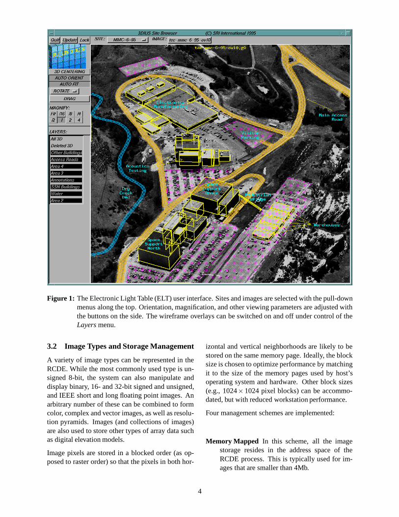
Figure 1: The Electronic Light Table (ELT) user interface. Sites and images are selected with the pull-downmenus along the top. Orientation, magnification, and other viewing parameters are adjusted withthe buttons on the side. The wireframe overlays can be switched on and off under control of theLayersmenu.
3.2 Image Types and Storage Management
A variety of image types can be represented in theRCDE. While the most commonly used type is un-signed 8-bit, the system can also manipulate anddisplay binary, 16- and 32-bit signed and unsigned,and IEEE short and long floating point images. Anarbitrary number of these can be combined to formcolor, complex and vector images, as well as resolu-tion pyramids. Images (and collections of images)are also used to store other types of array data suchas digital elevation models.
Image pixels are stored in a blocked order (as op-posed to raster order) so that the pixels in both hor-
izontal and vertical neighborhoods are likely to bestored on the same memory page. Ideally, the blocksize is chosen to optimize performance by matchingit to the size of the memory pages used by host’soperating system and hardware. Other block sizes(e.g., 1024×1024 pixel blocks) can be accommo-dated, but with reduced workstation performance.
Four management schemes are implemented:
Memory Mapped In this scheme, all the imagestorage resides in the address space of theRCDE process. This is typically used for im-ages that are smaller than 4Mb.
4
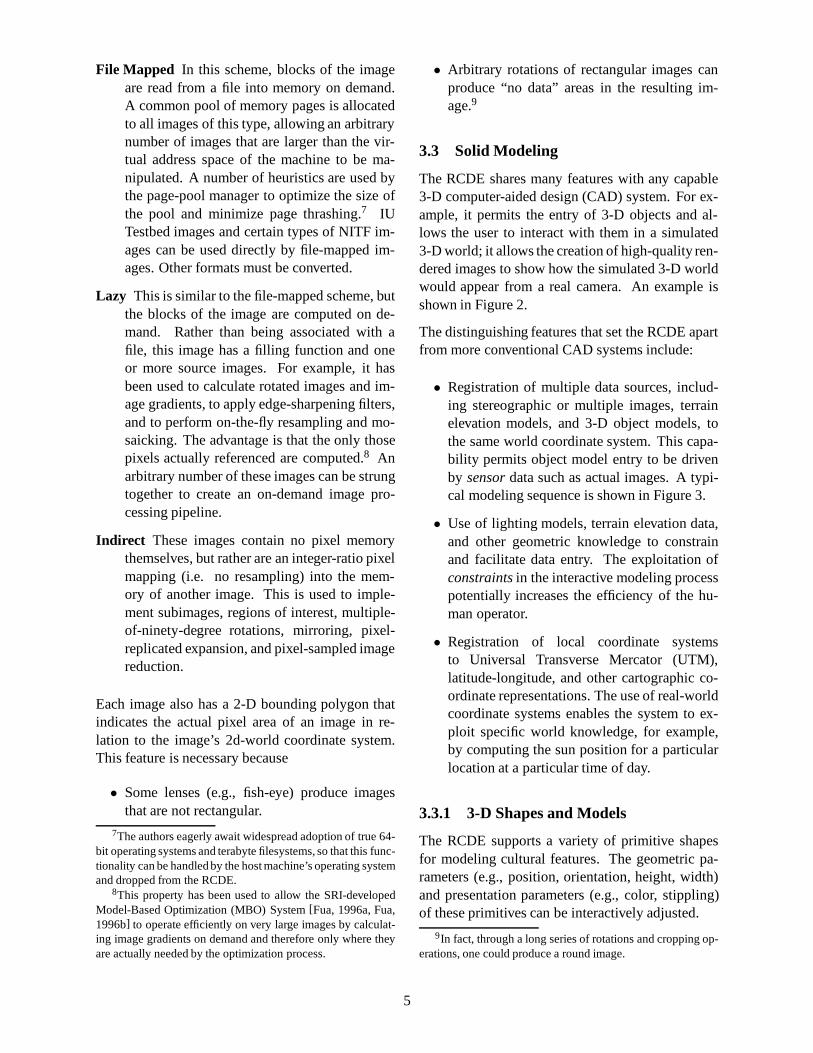
File Mapped In this scheme, blocks of the imageare read from a file into memory on demand.A common pool of memory pages is allocatedto all images of this type, allowing an arbitrarynumber of images that are larger than the vir-tual address space of the machine to be ma-nipulated. A number of heuristics are used bythe page-pool manager to optimize the size ofthe pool and minimize page thrashing.7 IUTestbed images and certain types of NITF im-ages can be used directly by file-mapped im-ages. Other formats must be converted.
Lazy This is similar to the file-mapped scheme, butthe blocks of the image are computed on de-mand. Rather than being associated with afile, this image has a filling function and oneor more source images. For example, it hasbeen used to calculate rotated images and im-age gradients, to apply edge-sharpening filters,and to perform on-the-fly resampling and mo-saicking. The advantage is that the only thosepixels actually referenced are computed.8 Anarbitrary number of these images can be strungtogether to create an on-demand image pro-cessing pipeline.
Indirect These images contain no pixel memorythemselves, but rather are an integer-ratio pixelmapping (i.e. no resampling) into the mem-ory of another image. This is used to imple-ment subimages, regions of interest, multiple-of-ninety-degree rotations, mirroring, pixel-replicated expansion, and pixel-sampled imagereduction.
Each image also has a 2-D bounding polygon thatindicates the actual pixel area of an image in re-lation to the image’s 2d-world coordinate system.This feature is necessary because
• Some lenses (e.g., fish-eye) produce imagesthat are not rectangular.
7The authors eagerly await widespread adoption of true 64-bit operating systems and terabyte filesystems, so that this func-tionality can be handled by the host machine’s operating systemand dropped from the RCDE.
8This property has been used to allow the SRI-developedModel-Based Optimization (MBO) System[Fua, 1996a, Fua,1996b] to operate efficiently on very large images by calculat-ing image gradients on demand and therefore only where theyare actually needed by the optimization process.
• Arbitrary rotations of rectangular images canproduce “no data” areas in the resulting im-age.9
3.3 Solid Modeling
The RCDE shares many features with any capable3-D computer-aided design (CAD) system. For ex-ample, it permits the entry of 3-D objects and al-lows the user to interact with them in a simulated3-D world; it allows the creation of high-quality ren-dered images to show how the simulated 3-D worldwould appear from a real camera. An example isshown in Figure 2.
The distinguishing features that set the RCDE apartfrom more conventional CAD systems include:
• Registration of multiple data sources, includ-ing stereographic or multiple images, terrainelevation models, and 3-D object models, tothe same world coordinate system. This capa-bility permits object model entry to be drivenby sensordata such as actual images. A typi-cal modeling sequence is shown in Figure 3.
• Use of lighting models, terrain elevation data,and other geometric knowledge to constrainand facilitate data entry. The exploitation ofconstraintsin the interactive modeling processpotentially increases the efficiency of the hu-man operator.
• Registration of local coordinate systemsto Universal Transverse Mercator (UTM),latitude-longitude, and other cartographic co-ordinate representations. The use of real-worldcoordinate systems enables the system to ex-ploit specific world knowledge, for example,by computing the sun position for a particularlocation at a particular time of day.
3.3.1 3-D Shapes and Models
The RCDE supports a variety of primitive shapesfor modeling cultural features. The geometric pa-rameters (e.g., position, orientation, height, width)and presentation parameters (e.g., color, stippling)of these primitives can be interactively adjusted.
9In fact, through a long series of rotations and cropping op-erations, one could produce a round image.
5
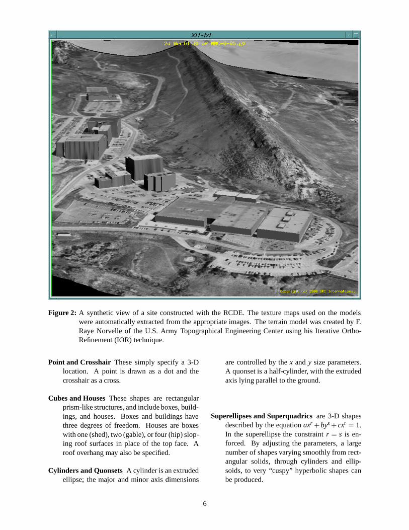
Figure 2: A synthetic view of a site constructed with the RCDE. The texture maps used on the modelswere automatically extracted from the appropriate images. The terrain model was created by F.Raye Norvelle of the U.S. Army Topographical Engineering Center using his Iterative Ortho-Refinement (IOR) technique.
Point and Crosshair These simply specify a 3-Dlocation. A point is drawn as a dot and thecrosshair as a cross.
Cubes and HousesThese shapes are rectangularprism-like structures, and include boxes, build-ings, and houses. Boxes and buildings havethree degrees of freedom. Houses are boxeswith one (shed), two (gable), or four (hip) slop-ing roof surfaces in place of the top face. Aroof overhang may also be specified.
Cylinders and QuonsetsA cylinder is an extrudedellipse; the major and minor axis dimensions
are controlled by thex andy size parameters.A quonset is a half-cylinder, with the extrudedaxis lying parallel to the ground.
Superellipses andSuperquadrics are 3-D shapesdescribed by the equationaxr + bys+ cxt = 1.In the superellipse the constraintr = s is en-forced. By adjusting the parameters, a largenumber of shapes varying smoothly from rect-angular solids, through cylinders and ellip-soids, to very “cuspy” hyperbolic shapes canbe produced.
6

The original images.
Sketch roof-line(Add Vertex).
Done with roof-line(Drop).
Correct elevation(MBO–Z-Search).
Optimize Shape(MBO–Opt)... Done!
Figure 3: The sequence of steps used to model a complex-shaped building with the extrusion primitive andthe SRI-authored Model-Based Optimization system. This entire sequence typically takes lessthan 1 minute of elapsed time.
7
Polyhedra are represented as a collection of ver-tices and a network of edges that connect them.Closed cycles of edges can be grouped into aface and assigned independent properties, suchas texture maps.
Open and Closed Curvesare space curves speci-fied by a list of 3-D vertices. The location andnumber of the vertices can be interactively ad-justed. They are drawn either as a polylineor a spline whose tension can be adjusted. Ifthe curve is closed, the last vertex is connectedback to the first.
Extrusions are closed curves that have an addi-tionalzvalue associated with each vertex. Thissets the length or height of the extrusion at eachpoint.
Ribbons and Curtains are open curves that havea width associated with each vertex and areused for modeling roads, rivers, fences, and soforth. For ribbons, the parallel lines are sepa-rated horizontally; for curtains, they are sepa-rated vertically. They may be drawn directly asentered, or have a spline fit to them.
DTM Mesh This is a regular network of four-(quad-mesh) or six- (tri-mesh) connected ver-tices whosez values are derived from a digitalterrain model.
Contour Map This object displays a set of con-tours of constant elevation computed from adigital terrain model. The elevation spacingcan be set to any convenient quantity.
Map Grid This object displays lines of constantlatitude and longitude or UTM coordinates.
Text displays a string of text at a 3-D location in asite.
Composite Objects This object controls a collec-tion of other objects belonging to the same co-ordinate system. When user interface opera-tions (such as motion, rotation, or cloning) areperformed on composite objects, the operationis performed on each object in the collection.
Many of these objects have 2-D counterparts thatcan be used for annotation of a particular image or
to represent and display the output of 2-D featureextraction processes, such as an edge detector.
3.4 Coordinates, Coordinate Transforms,and Coordinate Systems
A uniform structure for handling coordinates, co-ordinate transforms, and coordinate systems sim-plifies the implementation, increases the generality,and improves the performance of the RCDE.
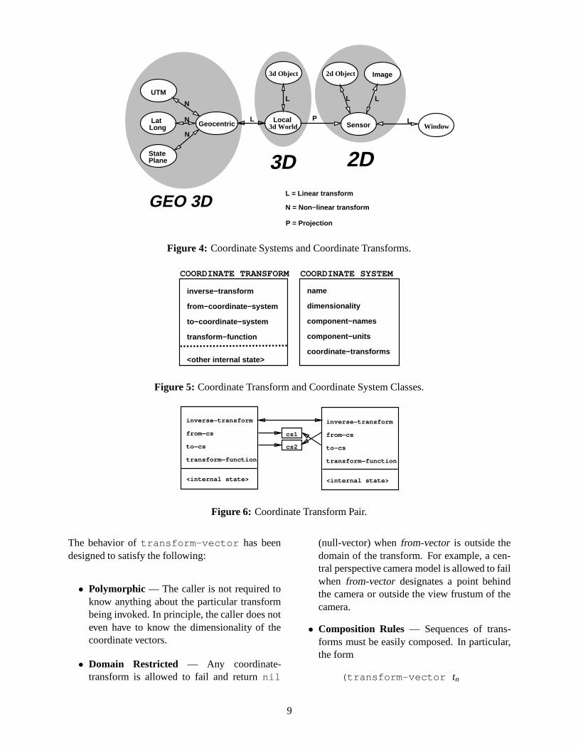
The RCDE is required to efficiently perform lin-ear, nonlinear, and projective coordinate transfor-mations between a large variety of coordinate sys-tems, as shown in Figure 4. In this network, nodes(ellipses) represent coordinate systems, and directedarcs represent coordinate-transforms. Note that allthe transforms shown are reversible except for theprojection from local 3d-world coordinates to sen-sor coordinates, which will be discussed later.
3.4.1 Coordinate Vectors
Spatial coordinates are represented by vectors (one-dimensional arrays) of double floats. In a prelimi-nary implementation of the RCDE, it was found ex-tremely awkward to pass coordinates to functionsas groups of individual scalar arguments. This wasdue to both the number of arguments to functionsand the local variable bindings needed to hold thereturned coordinates, as well as the awkward con-structs needed to perform sequences of coordinatetransforms.
3.4.2 Coordinate Transforms
Coordinate transforms are represented in the RCDEby using an object-oriented approach in which eachcoordinate transform is represented by an instanceof a coordinate-transform class with slots as shownin Figure 5.
Coordinate transforms are invoked fromprograms by calling the generic functiontransform-vector .
(transform-vector transformfrom-vector &optional to-vector)⇒ result-vector
8
Geocentric LatLong
UTM
StatePlane
N
N
NWindow3d World
3d Object 2d Object Image
L L L
LPLocalL
L = Linear transform
N = Non−linear transform
P = Projection
3D 2D
Sensor
GEO 3D
Figure 4: Coordinate Systems and Coordinate Transforms.
inverse−transform
from−coordinate−system
to−coordinate−system
transform−function
<other internal state>
COORDINATE TRANSFORM
name
dimensionality
component−names
component−units
coordinate−transforms
COORDINATE SYSTEM
Figure 5: Coordinate Transform and Coordinate System Classes.
inverse−transform
from−cs
to−cs
transform−function
<internal state>
cs1
cs2
inverse−transform
from−cs
to−cs
transform−function
<internal state>
Figure 6: Coordinate Transform Pair.
The behavior oftransform-vector has beendesigned to satisfy the following:
• Polymorphic — The caller is not required toknow anything about the particular transformbeing invoked. In principle, the caller does noteven have to know the dimensionality of thecoordinate vectors.
• Domain Restricted — Any coordinate-transform is allowed to fail and returnnil
(null-vector) whenfrom-vector is outside thedomain of the transform. For example, a cen-tral perspective camera model is allowed to failwhen from-vector designates a point behindthe camera or outside the view frustum of thecamera.
• Composition Rules — Sequences of trans-forms must be easily composed. In particular,the form
(transform-vector tn
9

.. .(transform-vector t2
(transform-vector t1from-vector)) · · ·)
must be guaranteed to apply the sequence oftransforms (t1 t2 · · · tn) to from-vectorand re-turnnil if any of the transforms returnsnil .(This implies thattransform-vector re-turnsnil wheneverfrom-vectoris nil ).
For convenience, the form
(transform-vectortransform-list from-vector)
wheretransform-list= (t1 t2 · · · tn) is equiv-alent to the previous set of nested calls totransform-vector .
Invertible Coordinate Transforms Nonsingularlinear transforms from n-space to n-space are invert-ible. Likewise, many nonlinear transforms, such asfrom geocentric to latitude-longitude coordinates,are invertible for vectors within the domain of thetransforms. This relationship is illustrated in Fig-ure 6.
Coordinate Projections A coordinate projectionis a special type of coordinate transform thatprojects from a coordinate system to a lower-dimensional coordinate system. Thus, without ad-ditional information, a coordinate projection can-not be inverted. Central perspective projection (pin-hole camera) and orthographic projection are themost common forms of coordinate projection usedin computer graphics.
Inverse Coordinate Projections An inverse co-ordinate projection transforms a coordinate vectorfrom a coordinate system (2-D) to a higher dimen-sional coordinate system (3-D) by ray-tracing tothe nearest point on a surface specified as an inter-nal state variable of the inverse projection. In theRCDE, the surface is usually either a terrain model(DTED) or a plane of constant elevation. In themost general case, the ray is the locus of points in a3-D space that project to the point of interest in the2-D sensor coordinate system. For electro-optical
(E-O) sensors the ray is a straight line, possibly per-turbed by atmospheric refraction; for synthetic aper-ture radar (SAR) sensors, the ray is an arc of a circle,possibly perturbed by refraction.
3.4.3 Coordinate Systems
Coordinate system objects are selectively used bythe RCDE for representing the network that con-nects coordinate systems by coordinate transforms,for user interface access to information such as thecoordinate system name and the coordinate compo-nent units and names, and for run-time error check-ing.10
The generic functionfind-transform searchesthe network accessible fromfrom-coordinate-systemto find a path toto-coordinate-system.
(find-transformfrom-coordinate-systemto-coordinate-system) ⇒ transform
When multiple paths exist between the coordinatesystems, the choice can be resolved based on mini-mal number of transforms in the sequence, minimaltransform error, or minimal computation time.
All the commonly used cartographic coordinatesystems, reference spheroids, geoids, and datums,and appropriate transformations between them, areavailable in the RCDE and can be manipulated withthe machinery described here.
Each 3-D model object is parameterized in its ownlocal rectangular coordinate system and has anobject-to-world-transformthat encodes its relation-ship to the site’slocal-vertical-coordinate-system(LVCS). The LVCS is a right-handed, Cartesian co-ordinate system (usually oriented so thatz is up andy points north) that is established for each site be-fore it is modeled. The LVCS in turn, has anLVCS-to-geocentric-transformthat is used to relate it to ageocentric coordinate system, and ultimately to ge-ographic coordinate systems such as latitude, longi-tude, and elevation in WGS-84 (the geographic co-ordinates used by the Global Positioning System).
10The implementation oftransform-vector does notrequire the use of coordinate system objects. If omitted, therun-time error checking is disabled.
10

Through this chain of transformations, every pointof every model object is fully georeferenced.
3.4.4 The RCDE Coordinate TransformPipeline
The RCDE implements the coordinate transformpipeline shown in Figure 7. The shaded ellipsesindicate the major points of contact between theRCDE user interface and the coordinate transformsand object representations.
3.5 Sensor Models
The dominant use of a sensor model in the RCDEis to project 3-space coordinates to image coor-dinates required during wire-frame model render-ing. To support smooth interaction with the ob-ject models, this projection must be fast (i.e., under50µs). For central projection cameras, the 3-D to2-D projection can be accomplished with as few as20 floating-point operations, taking less than 5µs ona Sun SPARCstation.
The RCDE can also accommodate images gener-ated by dynamic sensors, in which the image forma-tion process involves movement of parts of the sen-sor or the entire sensor platform itself, such as thestrip cameras used for aerial mapping or the imag-ing systems used in photo-reconnaissance satel-lites [McDonald, 1995]. Full mathematical mod-els of sensors of this type typically require two or-ders of magnitude more computation than for a cen-tral projection camera. To address this problem,the RCDE has facilities to fit and use a piecewisepolynomial approximation (commonly referred toas thefast block-interpolation projectionor FBIP)to the full mathematical model, as well as beingable to import and make use of rational polynomialfunction approximations (RPCs) generated by pho-togrammetric workstations such as GDE’s SOCETSET.
Since the RCDE must deal with a variety of imageand sensor types, a very general interface frame-work was developed. The only explicit knowledgeassumed about the sensor model is obtained fromeither its world-to-sensor projection functionP(X)or its sensor-to-world projection functionP−1(U).The actual implementation of the projection func-
tions is arbitrary, so long as specific mathematicalproperties are maintained. In particular, the projec-tion functionsP and P−1 are expected to be wellbehaved such that the local differential geometryexpressed by the Jacobian matrix of the projectionfunction characterizes a fairly large local neighbor-hood.
In general, there is no explicit knowledge of sen-sor position, sensor orientation, focal length, andso forth. We have found that most calculations thatuse these parameters in graphical user interfaces andIU algorithms can be replaced by counterparts de-rived from only the projection function and its Ja-cobian matrix. Furthermore, given two sensor mod-els, there is no global concept of epipoles or epipo-lar geometry. However, in local neighborhoods, theepipolar relationship between two images can becomputed from their Jacobian matrices.
The two primary application program interface(API) functions are project-to-view andproject-to-world . Project-to-viewtakes a 3-D point and returns the image plane co-ordinates of the projection of the point. Every timea 3-D object is drawn on top of an image, this func-tion is called for each vertex of the object.11
Project-to-world is somewhat more compli-cated. It first computes the ray or curve12 in spacethat is defined by the locus of points that project tothe given point in the image plane, and then com-putes the intersection of that ray or curve with a sur-face, such as a terrain model or a plane of constantelevation. If this intersection fails, the function re-turnsnil ; otherwise, it returns the point of inter-section. This functionality can be exercised by us-ing the mouse to click on an image being displayedby the RCDE. In response, the RCDE displays boththe image coordinates and apparent 3-D coordinatesof the selected point.
One of the main advantages of this generic, sensor-model-independent API is that code can be devel-oped and tested in an unclassified environment withunclassified imagery, and then used in classified
11A caching scheme, described later, eliminates recomputingthe calls toproject-to-view except when 3-D coordinatesor camera models are modified.
12This occurs in the case of SAR imagery or when the 3-Dcoordinate system is non-Cartesian, as is the case with geo-graphic coordinates.
11

WindowCoords
Rigid ObjectMotions
SensorCoords
3d −> 2dProjection
3d WorldCoords
3d Object
Transform
2d Object
PanZoomRotate
from bundle adjustment or user interface
Transform
Vertex motions
Parametric adjustments
3d ObjectCoords
2d ObjectCoords
2d to Window
Object to WorldTransform
Object to World
Figure 7: Standard Coordinate Transform Pipeline.
imagery environments without significant modifica-tion. This ability has been key to the transfer ofIU technology from universities into the RADIUSTestbed System.
3.5.1 Central Perspective Camera
This is the standard eleven-parameter “pinhole”camera model. It can be directly instantiated fromthe internal and external parameters (x, y, z, ω,φ, κ, principal-point-u, principal-point-v, focal-length, skew, aspect-ratio),13 from an orthonormal4×3 projection matrix, or as the result of a spaceresection of an image. The RCDE also includes fa-cilities for decomposing arbitrary projection matri-ces (such as those arising from a direct linear trans-form resection) into standard parameters. In addi-tion, there are a number of user interface functionsthat can be used to dynamically adjust projectionsto create synthetic views of the modeled scene.
3.5.2 Orthographic Projection
The RCDE handles orthographic projections as aspecial case of the central perspective projection,
13For most applications,skewis fixed at zero andaspect-ratio is fixed at 1.
with the inverse of the focal-length, 1/ f , set to zero.These projections are commonly used to import ex-isting maps into the RCDE or to produce 2-D “cam-pus maps” from 3-D site models.
3.5.3 Fast Block Interpolation Projection
As mentioned earlier, the full math models for somesensor types are computationally so complex as tomake them unsuitable for use in an interactive sys-tem. The solution used in the RCDE is to employ anexisting (but too slow) implementation as a “blackbox” for generating tables for the new, faster (arbi-trarily precise) approximation. In all of the knownexisting math models, it is relatively inexpensive tocompute the ray in space corresponding to a givenpixel. Projection from a point in 3-space to the im-age may be much more expensive.
The multiplane fast block projective model dividesthe image into rectangular blocks of some speci-fied size, and defines a set of planes (usually threeplanes) of constant elevation in 3-space that spanthe range of elevations of the terrain. Thus 3-spaceis divided into volume cells defined by the pathsof the camera rays in 3-space at each of the blockcorners in the image, and the elevation planes in
12

3-space. The approach makes no explicit assump-tion about the sensor and, furthermore, the coordi-nate system is not required to be Cartesian, allowingthe direct projection from WGS-84<longitude, lat-itude, elevation> to image coordinates.
For each elevation plane of each block, eight param-eters,(a,b,c,d,e, f ,g,h), define the projection of a3-space point in that plane into image coordinates:
u =ax+by+cgx+hy+1
(1)
v =dx+ey+ fgx+hy+1
(2)
An arbitrary point in 3-space point< x,y,z> is pro-jected to image coordinates in the following steps:
• Determine which block contains the 3-spacepoint. In general, this involves a search overmany or all image blocks and the follow-ing nontrivial computation within each imageblock.
– For each block corner, interpolate thecorner position at the elevation of thegiven 3-space point. The interpolationformula is of the form
x = x0(z−z1)(z−z2)
(z0−z1)(z0−z2)+
x1(z−z0)(z−z2)
(z1−z0)(z1−z2)+
x2(z−z0)(z−z1)
(z2−z0)(z2−z1)(3)
y = y0(z−z1)(z−z2)
(z0−z1)(z0−z2)+
y1(z−z0)(z−z2)
(z1−z0)(z1−z2)+
y2(z−z0)(z−z1)
(z2−z0)(z2−z1)(4)
– Perform a point-in-polygon test to deter-mine if the given 3-space point is withinthis block.
• For each elevation< zi > in the block, computethe< ui,vi > projection of the 3-space point.
• Perform annth-order interpolation (n being thenumber of elevation planes) of the< ui,vi >image locations with z being the variable of in-terpolation. For three elevation planes we have
u = u0(z−z1)(z−z2)
(z0−z1)(z0−z2)+
u1(z−z0)(z−z2)
(z1−z0)(z1−z2)+
u2(z−z0)(z−z1)
(z2−z0)(z2−z1)(5)
v = v0(z−z1)(z−z2)
(z0−z1)(z0−z2)+
v1(z−z0)(z−z2)
(z1−z0)(z1−z2)+
v2(z−z0)(z−z1)
(z2−z0)(z2−z1)(6)
The multiplane block projective interpolationscheme is expensive to compute, especially whenthe image block containing the 3-space point is notknown. To improve performance, the followingheuristics have been implemented:
• Spatial and Temporal Coherence: When pro-jecting a new 3-space point, first try the im-age block of the last point projected. If thatfails, re-project the point using the parametersfrom the current block. Repeat until the pointprojects into the correct block. This processusually converges in two iterations.
• Vertex Cache: When projecting a vertex of aCME object, save the projected image posi-tion in a cache (hash table) associated with thatvertex. Subsequent projections of that vertexare avoided by using the cached image coor-dinates. Of course, the cache must be flushedif the 3-space coordinates of the vertex or thecamera parameters are changed.
3.5.4 Composite
Any one of the preceding projections can have anarbitrary sequence of 3-D-to-3-D transformationsprepended to it and an arbitrary sequence of 2-D-to-2-D transformations appended to it to form a com-posite projection. Where possible, elements of the
13
sequence are automatically collapsed to increase thecomputational efficiency of the overall projection.3-D-to-3-D transformations are typically used to ad-just nonparametric projections (e.g., FBIP) duringimage resections and bundle adjustments or to cre-ate dynamic views that retain the overall geometricqualities of the original projection. Nonlinear 2-D-to-2-D transformations are typically used to modelthe optical distortions in lenses. Linear 2-D-to-2-Dtransformations are used to define the transforma-tion from 2d-world (original image) coordinates todisplayed image coordinates, and from displayedimage coordinates to screen coordinates.
3.6 Image Registration
Image registration is the process of determiningand/or refining the internal and external parameters(e.g., position, orientation) of the sensor used to ac-quire the image. The RCDE has facilities to per-form single-image space resection, closed-form di-rect linear transform resection, and multiple-imagebundle adjustment in a covariance-weighted least-squares framework[Mikhail, 1976, Slama, 1980].If accurate, georeferenced ground control (possi-bly augmented by image-to-image tie points) isavailable, absolute parameters are derived. If onlyimage-to-image tie points are available, relative pa-rameters are computed.
The primary interface to this functionality is theRegistration Tool. The tool adds no new underlyingfunctionality to the RCDE, but rather packages ex-isting operations in a much more user-friendly fash-ion. The tool is designed to lead the user throughthe necessary steps to register a new image, withoutdetailed knowledge of the intricacies of photogram-metry.
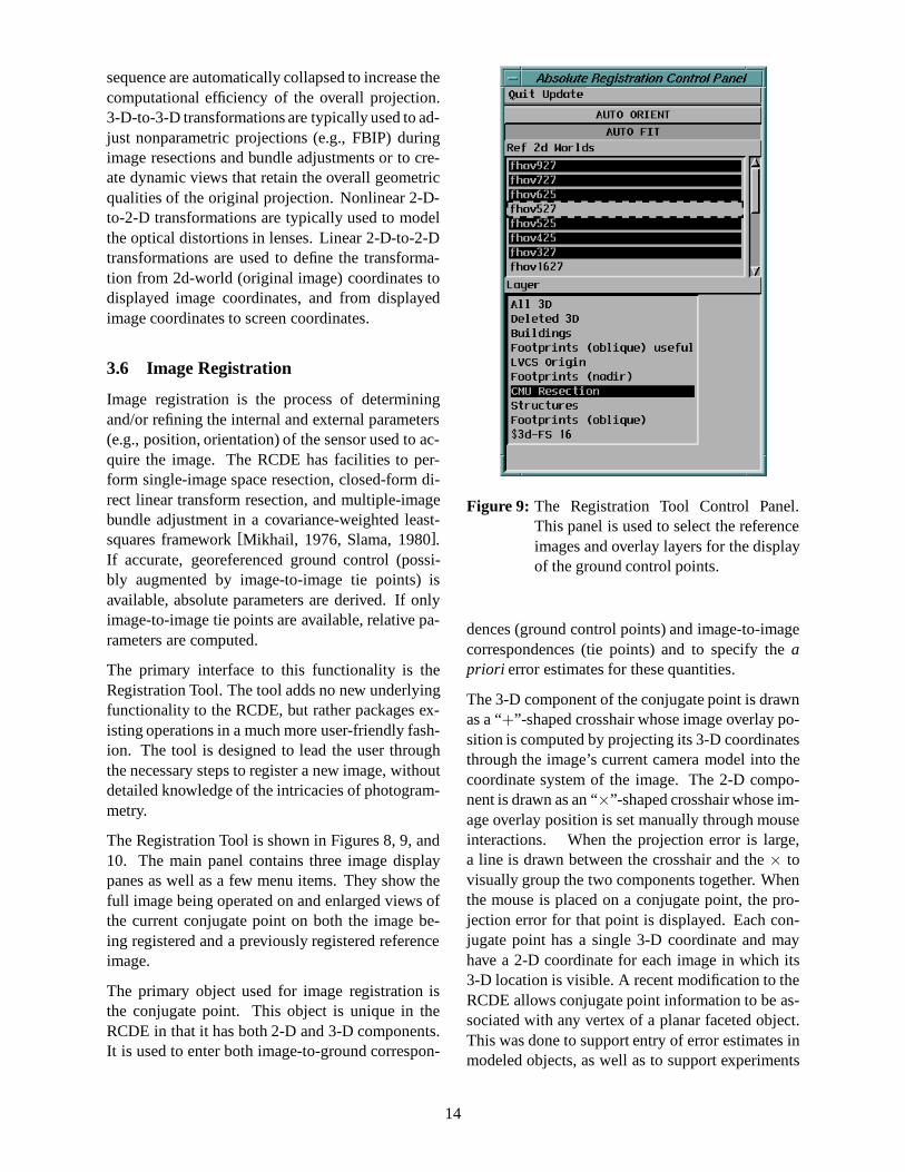
The Registration Tool is shown in Figures 8, 9, and10. The main panel contains three image displaypanes as well as a few menu items. They show thefull image being operated on and enlarged views ofthe current conjugate point on both the image be-ing registered and a previously registered referenceimage.
The primary object used for image registration isthe conjugate point. This object is unique in theRCDE in that it has both 2-D and 3-D components.It is used to enter both image-to-ground correspon-
Figure 9: The Registration Tool Control Panel.This panel is used to select the referenceimages and overlay layers for the displayof the ground control points.
dences (ground control points) and image-to-imagecorrespondences (tie points) and to specify theapriori error estimates for these quantities.
The 3-D component of the conjugate point is drawnas a “+”-shaped crosshair whose image overlay po-sition is computed by projecting its 3-D coordinatesthrough the image’s current camera model into thecoordinate system of the image. The 2-D compo-nent is drawn as an “×”-shaped crosshair whose im-age overlay position is set manually through mouseinteractions. When the projection error is large,a line is drawn between the crosshair and the× tovisually group the two components together. Whenthe mouse is placed on a conjugate point, the pro-jection error for that point is displayed. Each con-jugate point has a single 3-D coordinate and mayhave a 2-D coordinate for each image in which its3-D location is visible. A recent modification to theRCDE allows conjugate point information to be as-sociated with any vertex of a planar faceted object.This was done to support entry of error estimates inmodeled objects, as well as to support experiments
14
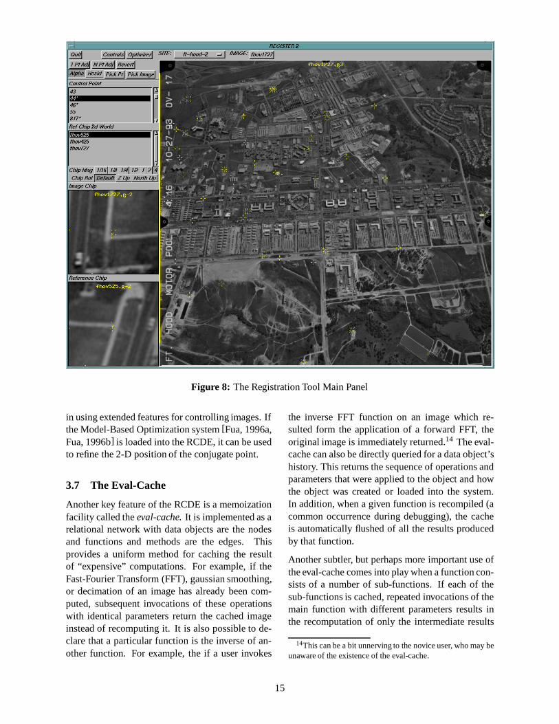
Figure 8: The Registration Tool Main Panel
in using extended features for controlling images. Ifthe Model-Based Optimization system[Fua, 1996a,Fua, 1996b] is loaded into the RCDE, it can be usedto refine the 2-D position of the conjugate point.
3.7 The Eval-Cache
Another key feature of the RCDE is a memoizationfacility called theeval-cache.It is implemented as arelational network with data objects are the nodesand functions and methods are the edges. Thisprovides a uniform method for caching the resultof “expensive” computations. For example, if theFast-Fourier Transform (FFT), gaussian smoothing,or decimation of an image has already been com-puted, subsequent invocations of these operationswith identical parameters return the cached imageinstead of recomputing it. It is also possible to de-clare that a particular function is the inverse of an-other function. For example, the if a user invokes
the inverse FFT function on an image which re-sulted form the application of a forward FFT, theoriginal image is immediately returned.14 The eval-cache can also be directly queried for a data object’shistory. This returns the sequence of operations andparameters that were applied to the object and howthe object was created or loaded into the system.In addition, when a given function is recompiled (acommon occurrence during debugging), the cacheis automatically flushed of all the results producedby that function.
Another subtler, but perhaps more important use ofthe eval-cache comes into play when a function con-sists of a number of sub-functions. If each of thesub-functions is cached, repeated invocations of themain function with different parameters results inthe recomputation of only the intermediate results
14This can be a bit unnerving to the novice user, who may beunaware of the existence of the eval-cache.
15
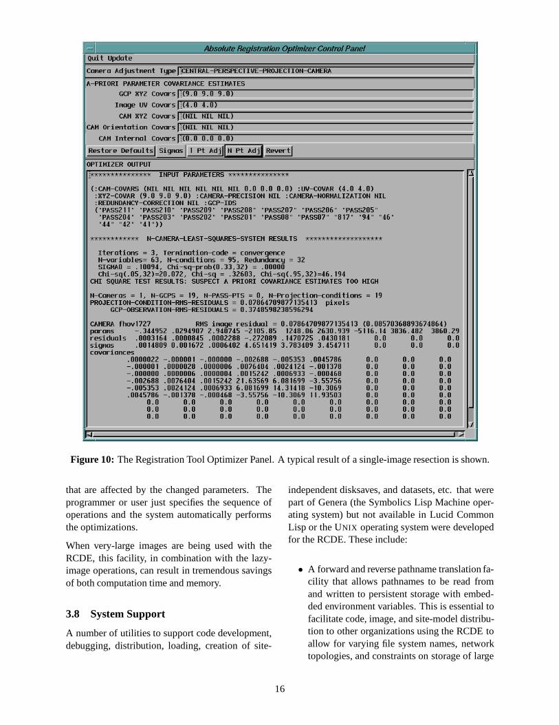
Figure 10: The Registration Tool Optimizer Panel. A typical result of a single-image resection is shown.
that are affected by the changed parameters. Theprogrammer or user just specifies the sequence ofoperations and the system automatically performsthe optimizations.
When very-large images are being used with theRCDE, this facility, in combination with the lazy-image operations, can result in tremendous savingsof both computation time and memory.
3.8 System Support
A number of utilities to support code development,debugging, distribution, loading, creation of site-
independent disksaves, and datasets, etc. that werepart of Genera (the Symbolics Lisp Machine oper-ating system) but not available in Lucid CommonLisp or the UNIX operating system were developedfor the RCDE. These include:
• A forward and reverse pathname translation fa-cility that allows pathnames to be read fromand written to persistent storage with embed-ded environment variables. This is essential tofacilitate code, image, and site-model distribu-tion to other organizations using the RCDE toallow for varying file system names, networktopologies, and constraints on storage of large
16
amounts of data.
• A patch facility that allows bug fixes and en-hancements to the system to be easily dis-tributed without creation and distribution anew RCDE executable. It enables the changesto be packaged into small files for distributionvia FTP that are automatically incrementallylinked into the executable when the system isstarted. This capability proved to be invalu-able for providing “rapid turnaround” modifi-cations to the RADIUS Testbed System. Thesepatches can also be installed into a runningcopy of the RCDE (see discussion below).
• A graphic data structure browser.
• A system construction facility that allows thespecification of loading and compilation pro-cedures for layered subsystems of code (e.g.,MBO, photogrammetry, NITF) as well as in-terdependencies among the subsystems.
• A facility that streamlines the creation of dis-tribution tapes for both code and data sets.
In addition, a development environment was buildaround the Lucid Common Lisp System, consistingof GNU Emacs, Ilisp, CVS, and other GNU utili-ties, that is distributed along with the RCDE. Thisallows us to keep a number of sets of the RCDEand RTS source code synchronized. Combined withthe facilities already present in the Lucid Com-mon Lisp System, it provides excellent support forrapid prototyping, code optimization, and debug-ging, through the use of the source code tracking,profiling, and tracing tools, data structure browsers,and incremental compilers and linkers.
One of the unique capabilities of high-performanceCommon Lisp systems in general, and Lucid Com-mon Lisp in particular, is the support for incremen-tal compilation and linking of both Lisp and C. Thevalue of this in a system that deals with very largedatasets, such as the RCDE, cannot be overempha-sized. By allowing patches to be installed into andexperimental changes to be made to a live, runningcopy of the RCDE, without corrupting the dynamicstate of the system execution (thereby, among otherthings, avoiding the need for the the data being used
to be reloaded), programming and debugging pro-ductivity is increased by at least an order of mag-nitude over conventional “segfault-modify-compile-relink-restart” types of code development environ-ments.15
4 Conclusions
Throughout the development of the RCDE and thesystems that preceded it, a number of innovativeideas and techniques were introduced. Many ofthese have become adopted as “standard practice”and now appear in commercial systems.
• Creation of an extensible, interactive, object-oriented, workstation-based image processingsystem.
• Tiled memory layout for image storage.
• The use of a memoization facility in an imageprocessing system (the eval-cache).
• The use of texture-mapping to perform imageperspective transformations and produce “fly-through” sequences.
• Joining CAD-system-like interactive 3-D mod-eling facilities and and image processing fa-cilities in a photogrammetrically rigorous andgeoreferenced framework.
• Object-oriented implementation of coordinate-system representations and coordinate-systemtransformation operations.
• The design and implementation of the genericsensor-model API.
• Lazy-evaluation image storage and operators.
In a paper of this length, we could not possiblycover all the functionality present in the RCDE andhave therefore concentrated on what we feel aresome of the key ideas in the system. A wealth of ad-ditional functionality is available (e.g., vector, ma-trix, and quaternion math, and computational ge-ometry libraries, an astronomical ephemeris, GUI
15With the possible exception of some implementations ofSmalltalk and Dylan, as well as some experimental, purely-functional languages such as Erlang, this capability is uniqueto Common Lisp systems, and in particular is absent from allknown implementations of C++ and Java.
17

libraries, an I/O sub-system for a variety of imageand data formats, nonlinear systems solvers). Infact, one of the main challenges in assembling theRADIUS Testbed System was building simple userinterfaces that allow the functionality in the RCDEto be used by someone who does not have a deepunderstanding of all the underlying theory and tech-nology.
Very few IU projects have had the level of success ofRADIUS in moving code from a research environ-ment into a quasi-operational environment where itcould be directly evaluated by image analysts on op-erational imagery. It is safe to say that without theRCDE there would be a great deal less code fromthe IU research community in the RADIUS TestbedSystem and much more time would have been spentin getting the code to interoperate. While a numberof systems, both commercial and research, providevarious subsets of the functionality of the RCDE,none provide the breadth and depth of facilities orcan match it in the ease with which it can be ex-tended and adapted to new applications.
The system continues to be developed, and we an-ticipate producing a version that runs on the SunUltraSPARC under Solaris in the near future, aswell as making use of OpenGL and new high-performance hardware for much of the graphics.
Acknowledgments
The authors wish to thank Christopher Connolly,Marty Fischler, and Oscar Firschein for reading pre-liminary drafts of this paper and making many sug-gestions that improved it. We would also like tothank Thomas Strat and Donald Gerson for encour-aging us to write it.
References
[Boult et al., 1994] Terrance E. Boult, Samuel D.Fenster, and Jason W. Kim. Dynamic Attributes,Code Generation and the IUE. InProceedingsof the DARPA Image Understanding Workshop,pages 405–422, 1994.
[Fua, 1996a] P. Fua. Cartographic Applicationsof Model-Based Optimization. InProceed-ings of the DARPA Image Understanding Work-shop, Palm Springs, CA, February 1996. Morgan
Kaufmann.
[Fua, 1996b] P. Fua. Model-Based Optimization:Accurate and Consistent Site Modeling. InXVIIIISPRS Congress, Vienna, Austria, July 1996.
[Gerson and Wood, 1994] D.J. Gerson and S.E.Wood. RADIUS Phase II: The RADIUS TestbedSystem. InProceedings: Image UnderstandingWorkshop, volume I, pages 231–237, Monterey,CA, 1994. ARPA, Morgan Kaufman.
[Hanson and Quam, 1988] A.J. Hanson and L.H.Quam. Overview of the SRI CartographicModeling Environment. InDARPA Image Un-derstanding Workshop, pages 576–582. MorganKaufman, 1988.
[Hansonet al., 1987] A.J. Hanson, A.P. Pentland,and L.H. Quam. Design of a prototype inter-active cartographic display and analysis environ-ment. In DARPA Image Understanding Work-shop, pages 475–482. Morgan Kaufman, 1987.
[Helleret al., 1996] A. J. Heller, P. Fua, C. Con-nolly, and J. Sargent. The Site-Model Construc-tion Component of the RADIUS Testbed Sys-tem. In Proceedings of the DARPA Image Un-derstanding Workshop, pages 345–355, 1996.
[McDonald, 1995] R.A. McDonald. CORONA:Success for Space Reconnaissance, a Look intothe Cold War, and a Revolution for Intelligence.PhotogrammetricEngineering and Remote Sens-ing, 61(6):689–720, 1995.
[Mikhail, 1976] E.M. Mikhail. Observations andLeast Squares. University Press of America,Lanham, New York, London, 1976.
[Mundyet al., 1992a] J. Mundy, T. Binford,T. Boult, A. Hanson, R. Beveridge, R. Haralick,V. Ramesh, C. Kohl, D. Lawton, D. Morgan,K. Price, and T. Strat. The Image UnderstandingEnvironments Program. InProceedings of theDARPA Image Understanding Workshop, pages185–226, 1992.
[Mundyet al., 1992b] J.L. Mundy, A. Noble,C. Marinos, V.D. Nguyen, A.J. Heller, J. Farley,and A.T. Tran. An object-oriented approach totemplate guided inspection. InCVPR92, pages386–392, 1992.
18

[Quam, 1985] L.H. Quam. The Terrain-Calc Sys-tem. InDARPA Image Understanding Workshop,pages 327–330. Morgan Kaufman, 1985.
[Slama, 1980] C.C. Slama, editor.Manual of Pho-togrammetry. American Society of Photogram-metry, fourth edition, 1980.
19