the ptp telecom profiles for frequency, phase and time synchronization
DESCRIPTION
Telecom SynchronizationTRANSCRIPT

Confidential © Copyright 2013
Tim Frost
Symmetricom, Inc.,
May 2013
The PTP Telecom Profiles for Frequency, Phase and Time Synchronization

2Confidential © Copyright 2013
Agenda
• Introduction to Precision Time Protocol (PTP)
– PTP Messages
– Impairments to Packet Timing
– Timing Support Elements (boundary and transparent clocks)
– PTP Profiles
• PTP Telecom Profile for Frequency (G.8265.1)
– Objectives and Design Features
– Source Traceability
– Multicast vs. Unicast messages
– Rate of Timing Messages
– Master Selection and Protection
• PTP Telecom Profiles for Time and Phase
– “Full Timing Support” (G.8275.1)
– “Partial Timing Support” (G.8275.2)
3Confidential © Copyright 2013
Introduction to Precision Time Protocol (PTP)
4Confidential © Copyright 2013
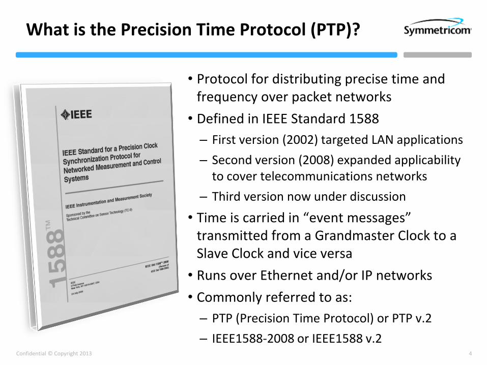
What is the Precision Time Protocol (PTP)?
• Protocol for distributing precise time and frequency over packet networks
• Defined in IEEE Standard 1588
– First version (2002) targeted LAN applications
– Second version (2008) expanded applicability to cover telecommunications networks
– Third version now under discussion
• Time is carried in “event messages” transmitted from a Grandmaster Clock to a Slave Clock and vice versa
• Runs over Ethernet and/or IP networks
• Commonly referred to as:
– PTP (Precision Time Protocol) or PTP v.2
– IEEE1588-2008 or IEEE1588 v.2
5Confidential © Copyright 2013
Sync message
t2
t1
Delay_Req message t3
t4
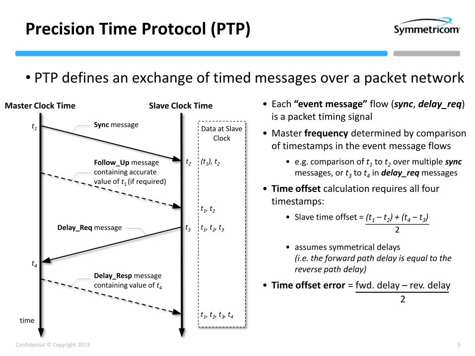
Precision Time Protocol (PTP)
• PTP defines an exchange of timed messages over a packet network
• Each “event message” flow (sync, delay_req) is a packet timing signal
• Master frequency determined by comparison of timestamps in the event message flows
• e.g. comparison of t1 to t2 over multiple syncmessages, or t3 to t4 in delay_req messages
• Time offset calculation requires all four timestamps:
• Slave time offset = (t1 – t2) + (t4 – t3)
• assumes symmetrical delays (i.e. the forward path delay is equal to the reverse path delay)
• Time offset error = fwd. delay – rev. delay
2
2
Master Clock Time Slave Clock Time
time
Delay_Resp message containing value of t4
Follow_Up messagecontaining accuratevalue of t1 (if required)
Data at Slave Clock
(t1), t2
t1, t2, t3
t1, t2, t3, t4
t1, t2

6Confidential © Copyright 2013
Net
wo
rk S
tack
Master Clock
PTP
UDP
IP
Ethernet
Physical
Net
wo
rk S
tack
Slave Clock
PTP
UDP
IP
Ethernet
Physical
Network
Receive queue
Transmit queue
Switching Element
Receive queue
Transmit queue
Switching Element
Receive queue
Transmit queue
Switching Element
Packet Timing Impairments
Timestamp generation
Timestamp generation
Hardware timestamp generation eliminates protocol stack delays

7Confidential © Copyright 2013
Boundary Clock
• A router or switch that contains an embedded PTP slave and PTP master, linked to the same local clock
• The PTP slave terminates the PTP traffic from the PTP Grandmaster, and synchronizes its local clock to the GM
• This local clock is used in turn to drive a new PTP master function
PTP Boundary ClockSwitch/Router
Switch function
Local Clock
PTP Slave
PTP Master
PTP messages PTP messages

8Confidential © Copyright 2013
“End to End” Transparent Clocks
• Measures time of packet arrival and packet departure
• Adds the difference (known as “residence time”) to a correction field in the packet header
• At the slave, the value of the correction field represents the total delay in each of the switches along the route
PTP “E2E” Transparent ClockSwitch/Router
Switch function
PTP messages
Arrival Time Departure Time
PTP messages
Residence Time BridgeModify
correction field

9Confidential © Copyright 2013
PTP “P2P” Transparent ClockSwitch/Router
Switch function
Residence Time Bridge
PTP “P2P” Transparent ClockSwitch/Router
Switch function
Residence Time Bridge
PTP “P2P” Transparent ClockSwitch/Router
Switch function
Residence Time Bridge
“Peer to Peer” Transparent Clocks
• Peer to peer messages measure the round trip link delay
• Link delay and residence time added to the correction field
• At the slave, the value of the correction field represents the total delay from master to slave
• Doesn’t require delay_request/response messages
Arrival Time Departure Time
PTP sync messages PTP sync messages
Peer-to-Peer messages
Peer-to-Peer messages
Departure Time Arrival Time
10Confidential © Copyright 2013
What is a PTP Profile?
• What is a profile?
– Profiles were introduced in IEEE1588-2008, to allow other standards bodies to tailor PTP to particular applications
– Profiles contain a defined combination of options and attribute values, aimed at supporting a given application
– Allows inter-operability between equipment designed for that purpose
• PTP Telecom Profile for Frequency (G.8265.1) published Oct. 2010
– Supports frequency synchronization over telecoms networks
– Main use-case is the synchronization of cellular basestations
The G.8265.1 PTP Telecom Profile enables the deployment of PTP-based frequency synchronization by telecoms operators
11Confidential © Copyright 2013
PTP Telecom Profiles for Time/Phase
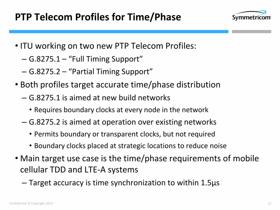
• ITU working on two new PTP Telecom Profiles:
– G.8275.1 – “Full Timing Support”
– G.8275.2 – “Partial Timing Support”
• Both profiles target accurate time/phase distribution
– G.8275.1 is aimed at new build networks
• Requires boundary clocks at every node in the network
– G.8275.2 is aimed at operation over existing networks
• Permits boundary or transparent clocks, but not required
• Boundary clocks placed at strategic locations to reduce noise
• Main target use case is the time/phase requirements of mobile cellular TDD and LTE-A systems
– Target accuracy is time synchronization to within 1.5µs

12Confidential © Copyright 2013
The PTP Telecom Profile for Frequency (G.8265.1)
13Confidential © Copyright 2013
Prime Objectives
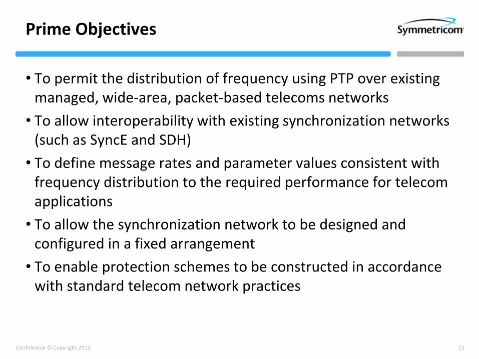
• To permit the distribution of frequency using PTP over existing managed, wide-area, packet-based telecoms networks
• To allow interoperability with existing synchronization networks (such as SyncE and SDH)
• To define message rates and parameter values consistent with frequency distribution to the required performance for telecom applications
• To allow the synchronization network to be designed and configured in a fixed arrangement
• To enable protection schemes to be constructed in accordance with standard telecom network practices
14Confidential © Copyright 2013
Key design decisions
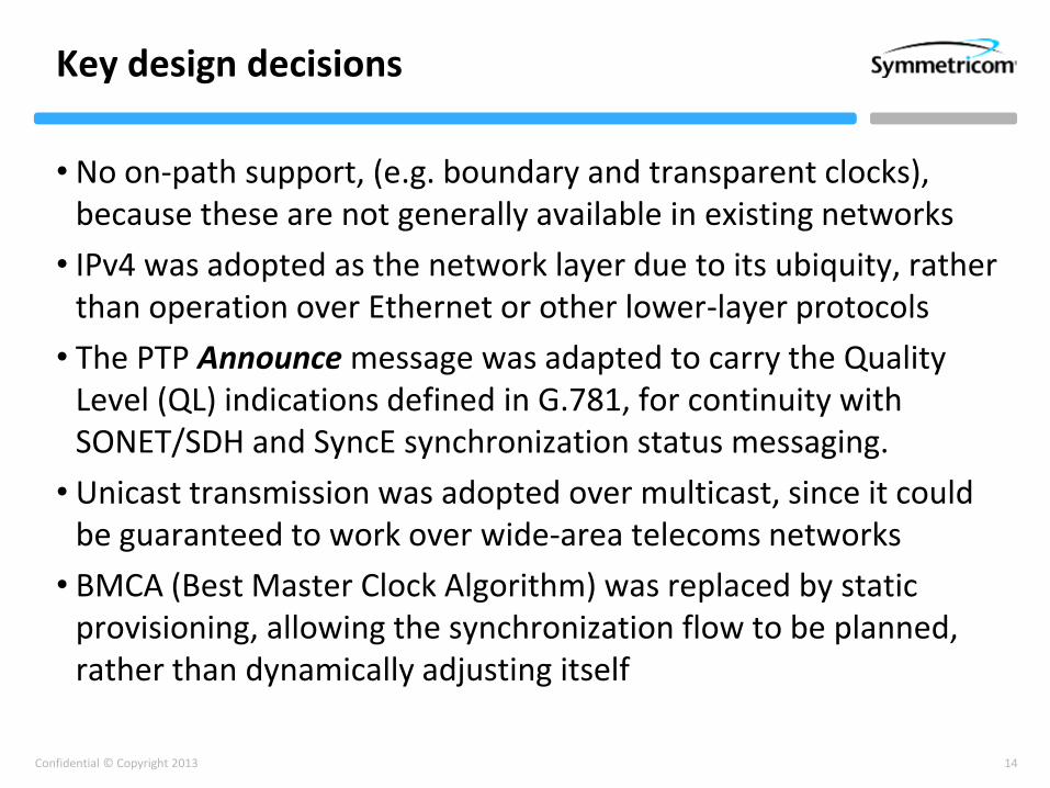
• No on-path support, (e.g. boundary and transparent clocks), because these are not generally available in existing networks
• IPv4 was adopted as the network layer due to its ubiquity, rather than operation over Ethernet or other lower-layer protocols
• The PTP Announce message was adapted to carry the Quality Level (QL) indications defined in G.781, for continuity with SONET/SDH and SyncE synchronization status messaging.
• Unicast transmission was adopted over multicast, since it could be guaranteed to work over wide-area telecoms networks
• BMCA (Best Master Clock Algorithm) was replaced by static provisioning, allowing the synchronization flow to be planned, rather than dynamically adjusting itself
15Confidential © Copyright 2013
Source Traceability
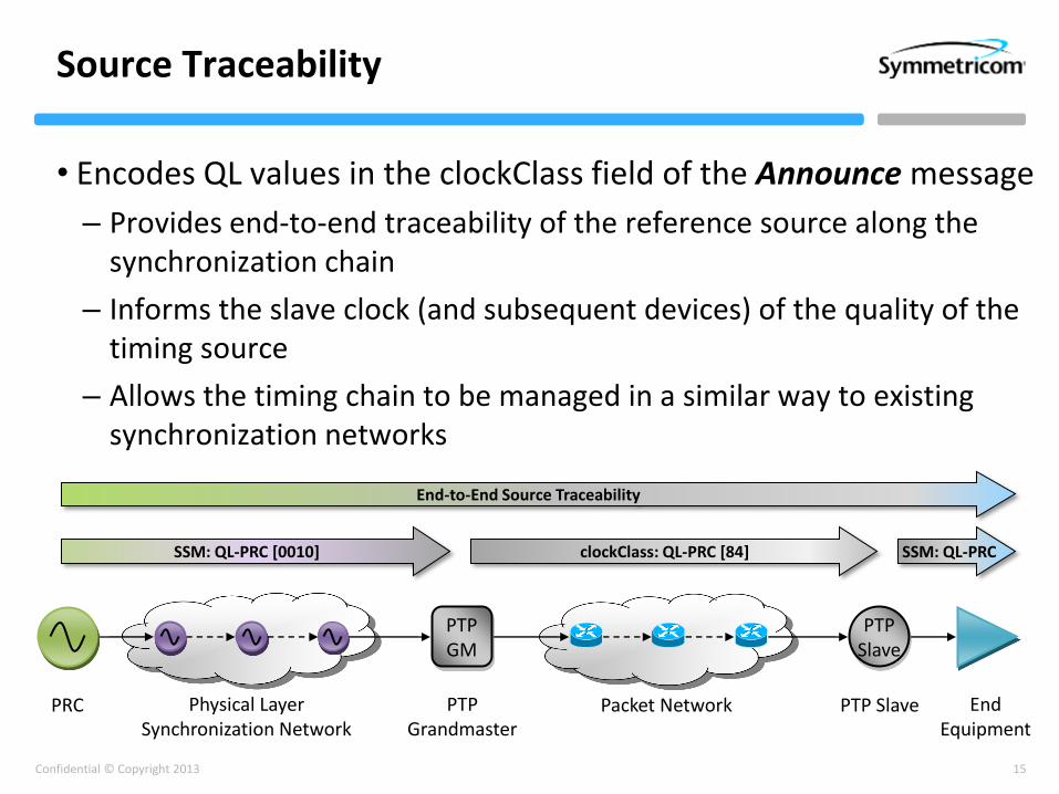
• Encodes QL values in the clockClass field of the Announce message
– Provides end-to-end traceability of the reference source along the synchronization chain
– Informs the slave clock (and subsequent devices) of the quality of the timing source
– Allows the timing chain to be managed in a similar way to existing synchronization networks
SSM: QL-PRC [0010] clockClass: QL-PRC [84]
End-to-End Source Traceability
PRC
PTP GM
EndEquipment
PTP Grandmaster
Packet NetworkPhysical Layer Synchronization Network
PTP Slave
PTP Slave
SSM: QL-PRC

16Confidential © Copyright 2013
Multicast vs. Unicast
• Unicast facilitates the use of distributed masters
– Each master-slave communication path becomes a separate PTP domain
– Allows easier planning of the synchronization network
– Redundancy strategy can be carefully managed
• Unicast packets propagate uniformly through the network
– Multicast requires packet replication at each switch or router
– Replication process adds variable delay
• Multicast harder to provision for network operators
– Upstream multicast often not supported in telecom networks
17Confidential © Copyright 2013
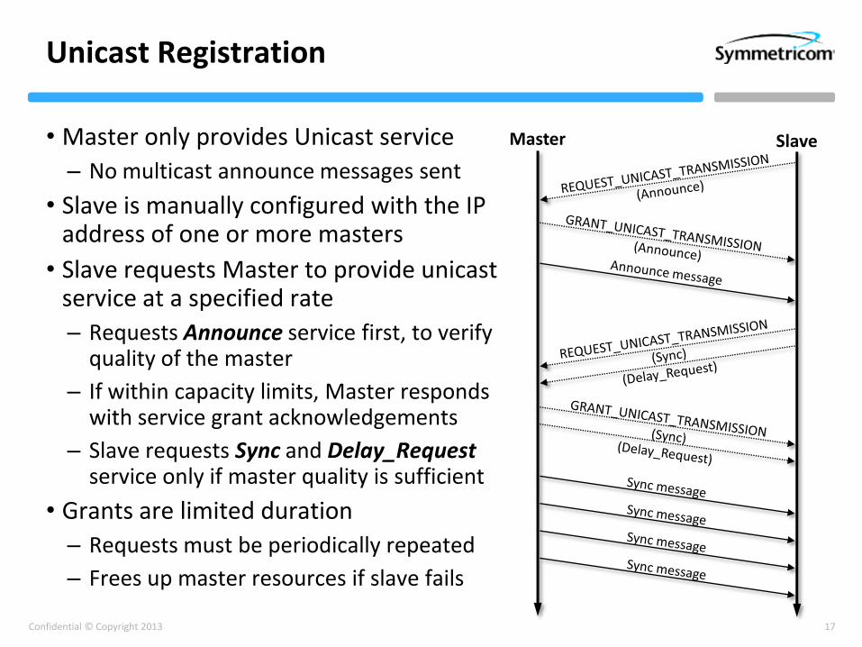
Unicast Registration
• Master only provides Unicast service
– No multicast announce messages sent
• Slave is manually configured with the IP address of one or more masters
• Slave requests Master to provide unicastservice at a specified rate
– Requests Announce service first, to verify quality of the master
– If within capacity limits, Master responds with service grant acknowledgements
– Slave requests Sync and Delay_Requestservice only if master quality is sufficient
• Grants are limited duration
– Requests must be periodically repeated
– Frees up master resources if slave fails
Master Slave
18Confidential © Copyright 2013
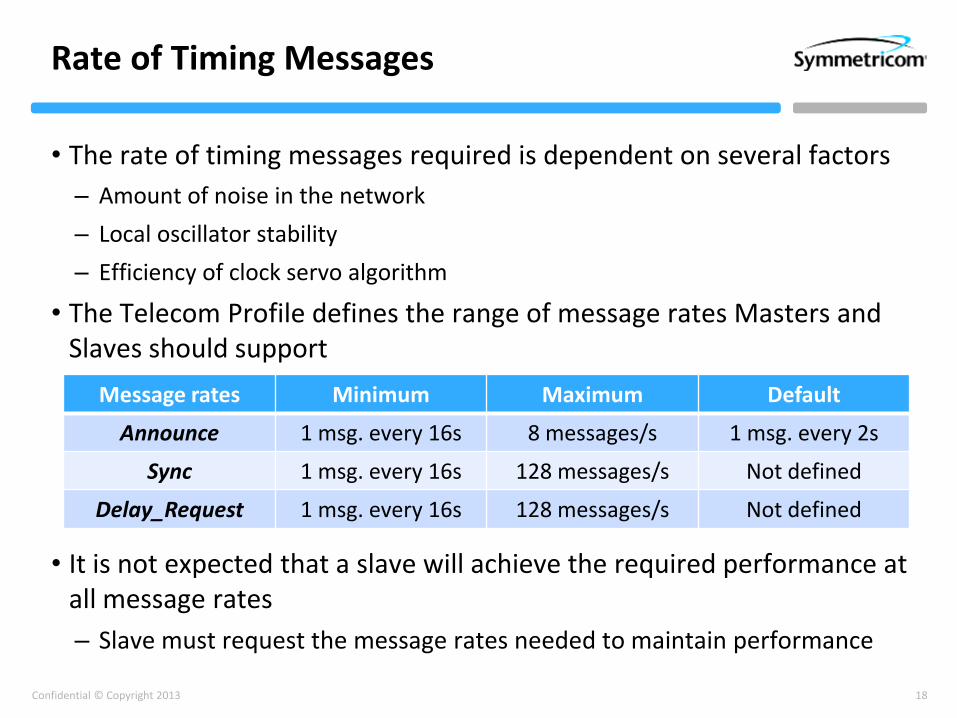
Rate of Timing Messages
• The rate of timing messages required is dependent on several factors
– Amount of noise in the network
– Local oscillator stability
– Efficiency of clock servo algorithm
• The Telecom Profile defines the range of message rates Masters and Slaves should support
• It is not expected that a slave will achieve the required performance at all message rates
– Slave must request the message rates needed to maintain performance
Message rates Minimum Maximum Default
Announce 1 msg. every 16s 8 messages/s 1 msg. every 2s
Sync 1 msg. every 16s 128 messages/s Not defined
Delay_Request 1 msg. every 16s 128 messages/s Not defined
19Confidential © Copyright 2013
Packet Timing Signal Fail
• Profile defines three types of signal failure:
– PTSF-lossAnnounce, where the PTP Slave is no longer receiving Announce messages from the GM
• This means there is no traceability information for that master
• Slave should switch to an alternative GM after a suitable timeout period
– PTSF-lossSync, where the PTP Slave is no longer receiving timing messages from the GM (i.e. Sync or Delay_Response messages)
• This means there is no timing information for that master
• Slave should switch to an alternative GM after a suitable timeout period
– PTSF-unusable, where the PTP Slave is receiving timing messages from the GM, but is unable to recover the clock frequency
• This means there is no recoverable timing information for that master
• Action is undefined
20Confidential © Copyright 2013
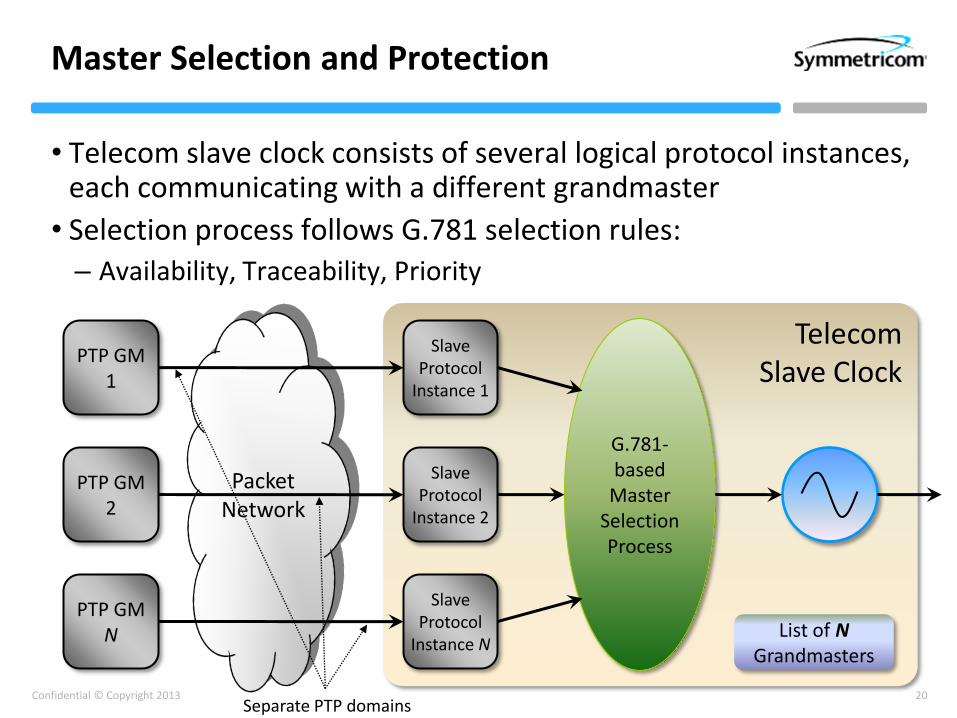
• Telecom slave clock consists of several logical protocol instances,each communicating with a different grandmaster
• Selection process follows G.781 selection rules:
– Availability, Traceability, Priority
Master Selection and Protection
Telecom Slave Clock
PTP GM1
PTP GM2
PTP GMN
Slave Protocol
Instance 1
Slave Protocol
Instance 2
Slave Protocol
Instance N
G.781-based
Master Selection Process
Packet Network
List of NGrandmasters
Separate PTP domains

21Confidential © Copyright 2013
Additional Protection Functions
• Non-reversion function
– Disables automatic reversion to original master after fault has been rectified
• Wait-to-Restore Time
– Defines the waiting period before switching back to the original highest priority master, once the failure condition has been rectified
• Forced traceability
– If the PTP GM is connected to a reference by a signal with no SSM QL value, the input can be manually “forced” to a suitable value
• Output QL Hold-Off
– Defines a waiting period following a change of QL in the incoming PTP clockClass before forwarding to downstream equipment
– Allows time for synchronization to a new reference
• Output Squelch
– Output clock signal of a PTP slave should be “squelched” in case of holdover
– Only applies to signals that do not carry a QL value (e.g. a 2.048MHz unframed timing signal)
22Confidential © Copyright 2013
The PTP Telecom Profiles for Time and Phase
23Confidential © Copyright 2013
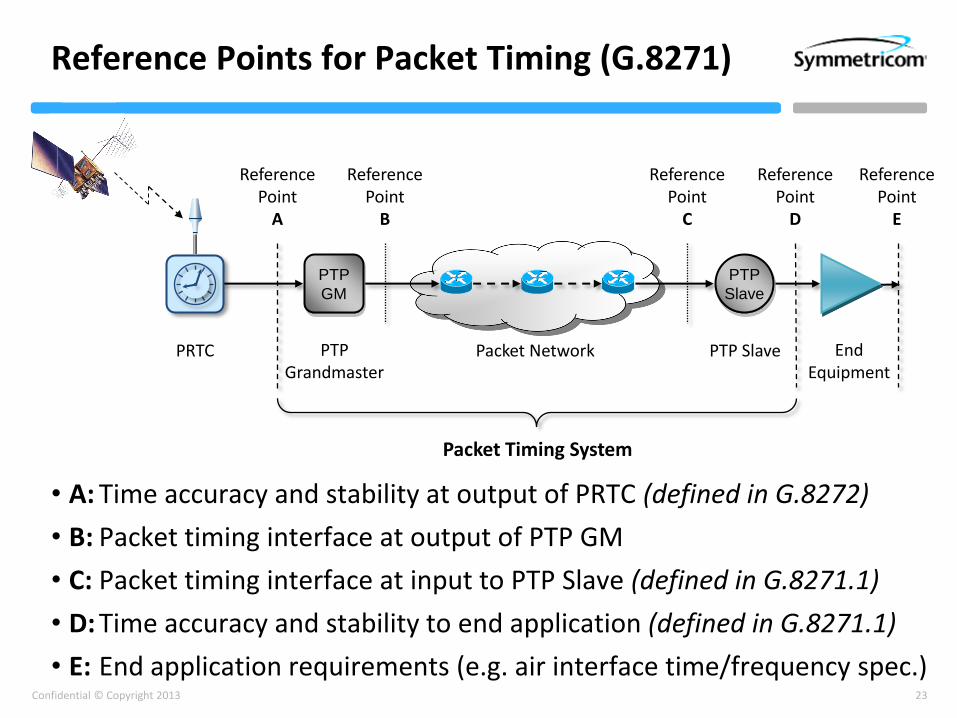
Reference Points for Packet Timing (G.8271)
• A: Time accuracy and stability at output of PRTC (defined in G.8272)
• B: Packet timing interface at output of PTP GM
• C: Packet timing interface at input to PTP Slave (defined in G.8271.1)
• D: Time accuracy and stability to end application (defined in G.8271.1)
• E: End application requirements (e.g. air interface time/frequency spec.)
PTP
GM
EndEquipment
PTP Grandmaster
Packet Network PTP Slave
PTP
Slave
Reference Point
A
Reference Point
B
Reference Point
C
Reference Point
D
Packet Timing System
Reference Point
E
PRTC
24Confidential © Copyright 2013
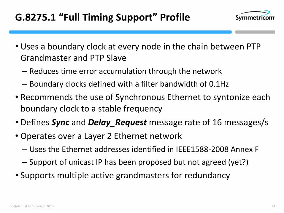
G.8275.1 “Full Timing Support” Profile
• Uses a boundary clock at every node in the chain between PTP Grandmaster and PTP Slave
– Reduces time error accumulation through the network
– Boundary clocks defined with a filter bandwidth of 0.1Hz
• Recommends the use of Synchronous Ethernet to syntonize each boundary clock to a stable frequency
• Defines Sync and Delay_Request message rate of 16 messages/s
• Operates over a Layer 2 Ethernet network
– Uses the Ethernet addresses identified in IEEE1588-2008 Annex F
– Support of unicast IP has been proposed but not agreed (yet?)
• Supports multiple active grandmasters for redundancy

25Confidential © Copyright 2013
Frequency Plane
Time Plane
PTP PTP PTP
End Application (e.g. eNodeB)
PTP GM PTP BC PTP BC PTP BC PTP TSC
Time reference (PRTC)
PTP
Hypothetical Reference Model
EEC EEC EEC EEC EEC
SyncE frequency distribution networks
PRC frequency references
[PRCs may be separate or common]
SyncE SyncE SyncE SyncE SyncE
Up to 10 BCs in a chain

26Confidential © Copyright 2013
Time Error Budget (G.8271.1)
±100 ns(PRTC)
±550 ns constant time error(±50 ns per node, 10 BCs + 1 slave)
±200 ns (dynamic time error)
±100 ns (network asymmetry compensation)
±400 ns (holdover budget)
±150 ns (end equip.)
±1.5 µs end-to-end budget
A, B C D E
Reference Points:
27Confidential © Copyright 2013
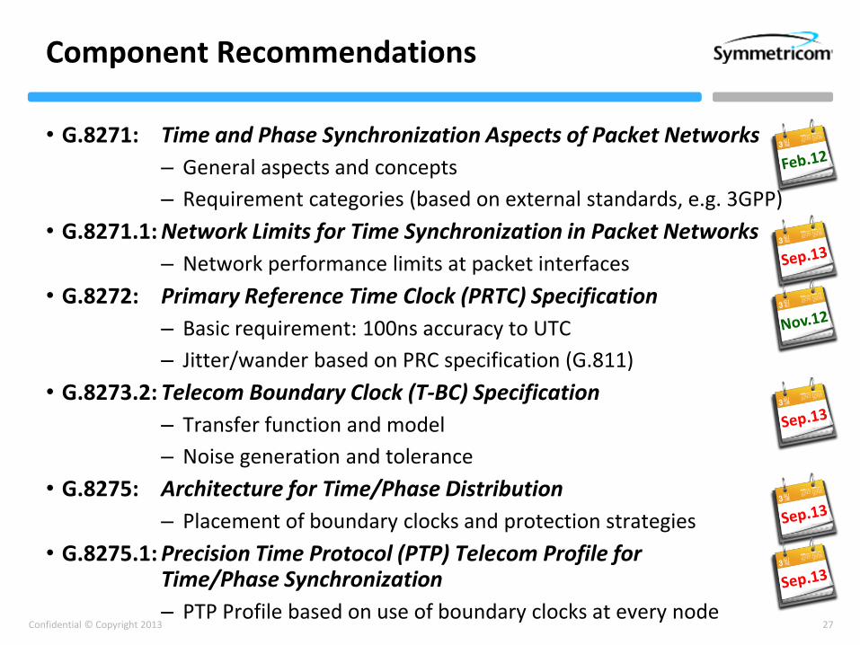
Component Recommendations
• G.8271: Time and Phase Synchronization Aspects of Packet Networks
– General aspects and concepts
– Requirement categories (based on external standards, e.g. 3GPP)
• G.8271.1: Network Limits for Time Synchronization in Packet Networks
– Network performance limits at packet interfaces
• G.8272: Primary Reference Time Clock (PRTC) Specification
– Basic requirement: 100ns accuracy to UTC
– Jitter/wander based on PRC specification (G.811)
• G.8273.2: Telecom Boundary Clock (T-BC) Specification
– Transfer function and model
– Noise generation and tolerance
• G.8275: Architecture for Time/Phase Distribution
– Placement of boundary clocks and protection strategies
• G.8275.1: Precision Time Protocol (PTP) Telecom Profile for Time/Phase Synchronization
– PTP Profile based on use of boundary clocks at every node

28Confidential © Copyright 2013
G.8275.2 “Partial Timing Support” Profile
• Why a second time/phase profile?
– Some service providers need to operate time/phase synchronisation over existing networks
– Reduces barriers to entry into LTE-A systems; don’t need to build an entirely new network
– Allows operation over 3rd party network providers (given appropriate quality guarantees)
• Result: “Partial Timing Support Profile”
– New ITU work item requested by four large service providers
– Expected to be published in 2014
• Key features:
– Operates over existing switches and routers, using unicast IP
– Uses boundary or transparent clocks where necessary to “clean up” time signal as it passes through the network
– Supports multiple active grandmasters for redundancy

29Confidential © Copyright 2013
For Further Reading
• White Paper:
– “Synchronization for Next Generation Networks – The PTP Telecom Profile”, Symmetricom White Paper, April 2012
• Primary References:
– “IEEE Standard for a Precision Clock Synchronization Protocol for Networked Measurement and Control Systems”, IEEE Std. 1588TM-2008, 24 July 2008
– “Precision Time Protocol Telecom Profile for Frequency Synchronization”, ITU-T Recommendation G.8265.1, October 2010
• Background Reading:
– “Synchronization Layer Functions”, ITU-T Recommendation G.781, August 2008
– “Definitions and terminology for synchronization in packet networks”, ITU-T Recommendation G.8260, August 2010
– “Timing and synchronization Aspects in Packet Networks”, ITU-T Recommendation G.8261, April 2008
– “Architecture and Requirements for Packet-Based Frequency Delivery”, ITU-T Recommendation G.8265, October 2010
– “Time and Phase Synchronization Aspects of Packet Networks”, ITU-T Recommendation G.8271, February 2012
– “Timing characteristics of Primary Reference Time Clocks (PRTC)”, ITU-T Recommendation G.8272, November 2012
• Under Development:
– “Network Limits for Time Synchronization in Packet Networks”, ITU-T Draft Recommendation G.8271.1 (exp. Sep. 2013)
– “Timing characteristics of Telecom Boundary Clocks (T-BC)”, ITU-T Draft Recommendation G.8273.2 (exp. Sep. 2013)
– “Architecture for Time/Phase Distribution”, ITU-T Draft Recommendation G.8275 (exp. Sep. 2013)
– “Precision Time Protocol (PTP) Telecom Profile for Time/Phase Synchronization using Full Timing Support”, ITU-T Draft Recommendation G.8275.1 (exp. Sep. 2013)
– “Precision Time Protocol (PTP) Telecom Profile for Time/Phase Synchronization using Partial Timing Support”, ITU-T Draft Recommendation G.8275.2 (exp. 2014)
30Confidential © Copyright 2013
Symmetricom, Inc.2300 Orchard ParkwaySan Jose, CA 95131-1017Tel: +1 408-428-7907Fax: +1 408-428-6960
www.symmetricom.com
Thank You
Tim FrostPrincipal Technologist,
Symmetricom, Inc.
Email: [email protected]