the proximity toolkit: prototyping proxemic interactions...
TRANSCRIPT
The Proximity Toolkit: Prototyping Proxemic Interactions in Ubiquitous Computing Ecologies
ABSTRACT People naturally understand and use proxemic relationships (e.g., their distance and orientation towards others) in every-day situations. However, only few ubiquitous computing (ubicomp) systems interpret such proxemic relationships to mediate interaction (proxemic interaction). A technical prob-lem is that developers find it challenging and tedious to ac-cess proxemic information from sensors. Our Proximity Toolkit solves this problem. It simplifies the exploration of interaction techniques by supplying fine-grained proxemic information between people, portable devices, large interac-tive surfaces, and other non-digital objects in a room-sized environment. The toolkit offers three key features. 1) It fa-cilitates rapid prototyping of proxemic-aware systems by supplying developers with the orientation, distance, motion, identity, and location information between entities. 2) It in-cludes various tools, such as a visual monitoring tool, that allows developers to visually observe, record and explore proxemic relationships in 3D space. (3) Its flexible architec-ture separates sensing hardware from the proxemic data model derived from these sensors, which means that a variety of sensing technologies can be substituted or combined to derive proxemic information. We illustrate the versatility of the toolkit with proxemic-aware systems built by students.
ACM Classification: H5.2 [Information interfaces]: User Interfaces – input devices and strategies, prototyping. General terms: Design, Human Factors Keywords: Proximity, proxemics, proxemic interactions, toolkit, development, ubiquitous computing, prototyping.
INTRODUCTION Ubicomp ecologies are now common, where people’s access to digital information increasingly involves near-simultaneous interaction with multiple nearby digital devices of varying size, e.g., personal mobile phones, tablet and desktop computers, information appliances, and large inter-active surfaces (Figure 1). This is why a major theme in ubiquitous computing is to explore novel forms of interaction not just between a person and a device, but also between a person and their set of devices [32]. Proxemic interaction is one strategy to mediate people’s interaction in room-sized ubicomp ecologies [2,9]. It is inspired by Hall’s Proxemic theory [11] about people’s understanding and use of inter-personal distances to mediate their interactions with others. In proxemic interaction, the belief is that we can design sys-tems that will let people exploit a similar understanding of their proxemic relations with their nearby digital devices, thus facilitating more seamless and natural interactions.
A handful of researchers have already explored proxemic-aware interactive systems. These range from spatially aware mobile devices [17], office whiteboards [15], public art installations [28], home media players [2], to large pub-lic ambient displays [31]. All developed novel interaction techniques as a function of proxemic relationships between people and devices.
Building proxemic-aware systems, however, is difficult. Even if sensing hardware is available, translating low-level sensing information into proxemic information is hard (e.g., calibration, managing noise, calculations such as 3D math). This introduces a high threshold for those wishing to develop proxemic interaction systems. As a result, most do not bother. Of the few that do, they spend most of their time with low-level implementation details to actually access and process proxemic information vs. refining the interaction concepts and techniques of interest.
Nicolai Marquardt1, Robert Diaz-Marino2, Sebastian Boring1, Saul Greenberg1
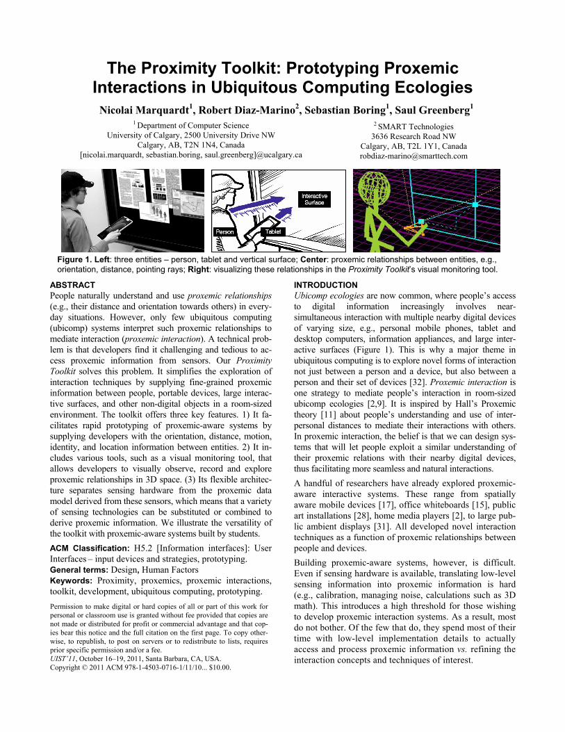
Figure 1. Left: three entities – person, tablet and vertical surface; Center: proxemic relationships between entities, e.g., orientation, distance, pointing rays; Right: visualizing these relationships in the Proximity Toolkit’s visual monitoring tool.
Permission to make digital or hard copies of all or part of this work for personal or classroom use is granted without fee provided that copies are not made or distributed for profit or commercial advantage and that cop-ies bear this notice and the full citation on the first page. To copy other-wise, to republish, to post on servers or to redistribute to lists, requires prior specific permission and/or a fee. UIST’11, October 16–19, 2011, Santa Barbara, CA, USA. Copyright © 2011 ACM 978-1-4503-0716-1/11/10... $10.00.
1 Department of Computer Science University of Calgary, 2500 University Drive NW
Calgary, AB, T2N 1N4, Canada [nicolai.marquardt, sebastian.boring, saul.greenberg]@ucalgary.ca
2 SMART Technologies 3636 Research Road NW
Calgary, AB, T2L 1Y1, Canada [email protected]

To alleviate this problem, we built the Proximity Toolkit. Our goal was to facilitate rapid exploration of proxemic interaction techniques. To meet this goal, the Proximity Toolkit transforms raw tracking data gathered from various hardware sensors (e.g., infra-red motion capturing systems, depth sensing cameras) into rich high-level proxemic in-formation accessible via an event-driven object-oriented API. The toolkit includes a visual monitoring tool that dis-plays the physical environment as a live 3D scene and shows the proxemic relationships between entities within that scene. It also provides other tools: one to record events generated by entities for later playback during testing; an-other to quickly calibrate hardware and software. Thus our work offers three contributions: 1. The design of a toolkit architecture, which fundamen-
tally simplifies access to proxemic information. 2. Interpretation and representations of higher-level prox-
emic concepts (e.g., relationships, fixed/semi-fixed fea-tures) from low-level information.
3. The design of complementary visual tools that allow developers to explore proxemic relationships between entities in space without coding.
The remainder of the paper is structured as follows: we recap the concepts of proxemic interaction and derive chal-lenges for developers. We then introduce the design of our toolkit; we include a running example, which we use to illustrate all steps involved in prototyping a proxemic in-teraction system. Subsequently, we introduce our visual monitor and other tools, and explain the toolkit’s API. Next, we discuss the flexible toolkit architecture and im-plementation. This is followed by an overview of applica-tions built by others using our toolkit. Finally, we discuss related toolkit work in HCI.
BACKGROUND: PROXEMIC INTERACTION Proxemics – as introduced by anthropologist Edward Hall in 1966 [11] – is a theory about people’s understanding and use of interpersonal distances to mediate their interactions with other people. Hall’s theory correlates people’s physical dis-tance to social distance. He noticed zones that suggest certain types of interaction: from intimate (6-18”), to private (1.5-4’), social (4-12’), and public (12-25’). The theory further describes how the spatial layout of rooms and immovable objects (fixed features) and movable objects such as chairs (semi-fixed features) influence people’s perception and use of personal space when they interact [11].
Research in the field of proxemic interaction [2,9,31] in-troduces concepts of how to apply this theory to ubicomp interaction within a small area such as a room. In particu-lar, such ubicomp ecologies mediate interaction by exploit-ing fine-grained proxemic relationships between people, objects, and digital devices. The design intent is to leverage people’s natural understanding of their proxemic relation-ships to manage the entities that surround them.
Proxemic theories suggest that a variety of physical, social, and cultural factors influence and regulate interpersonal
interaction. Not all can be (or needs to be) directly applied to a proxemic ubicomp ecology. Thus the question is: what information is critical for ubicomp proxemics? Greenberg et al. [9] identified and operationalized five essential di-mensions as a first-order approximation of key proxemic measures that should be considered in ubicomp. 1. Orientation: the relative angles between entities; such
as if two people are facing towards one another. 2. Distance: the distance between people, objects, and
digital devices; such as the distance between a person and a large interactive wall display.
3. Motion: changes of distance and orientation over time; such as a person approaching a large digital surface to interact with it directly.
4. Identity: knowledge about the identity of a person, or a particular device.
5. Location: the setup of environmental features; such as the fixed-feature location of walls and doors, and the semi-fixed features including movable furniture.
Previous researchers have used a subset of these five di-mensions to build proxemic-aware interfaces that react more naturally and seamlessly to people’s expectations of proxemics. Hello Wall [29] introduced the notion of ‘dis-tance-dependent semantics’, where the distance of a person to the display defined the possible interactions and the in-formation shown on the display. Similarly, Vogel’s public ambient display [31] relates people’s presence in four dis-crete zones around the display to how they can interact with the digital content. Snibbe [28] investigated people’s use of proxemics in the Boundary Functions public interac-tive art installation, where they also noticed cultural differ-ences in people’s implicit use of proxemics (similar to Hall’s observations). Ju [15] explored transitions between implicit and explicit interaction with a proxemic-aware office whiteboard: interaction from afar is public and im-plicit, but becomes more explicit and private when closer. Ballendat et al. [2] developed a variety of proxemic-aware interaction techniques, illustrated through the example of a home media player application. Their system exploits al-most all of the 5 dimensions: it activates when the first per-son enters, reveals more content when approaching and looking at the screen, switches to full screen view when a person sits down, and pauses the video when the person is distracted (e.g., receiving a phone call). If a second person enters, the way that the information displays is altered to account for two viewers in the room [2].
This previous research in proxemic interaction opened up a promising direction of how to mediate people’s interaction with ubicomp technology based on proxemic relationships. The caveat is that they are really just starting points of how we can integrate proxemic measures into interaction de-sign. Further explorative research – including the develop-ment and evaluation of actual proxemic-aware systems – will help to refine our understanding of how proxemic the-ories apply to ubicomp.
DERIVED CHALLENGES FOR DEVELOPERS Building proxemic-aware systems such as the ones de-scribed previously is difficult and tedious. This is mostly due to the serious technical challenges that developers face when integrating proxemic information into their applica-tion designs. Several challenges are listed below. 1. Exploring and observing proxemic measures between
entities in the ecology. Developers need to do this to decide which measures are important in their scenario.
2. Accessing proxemic measurements from within soft-ware that is developed to control the ubicomp system. Developers currently do this through very low-level programming against a particular tracking technology, requiring complex 3D transformations and calculations, and often resulting in brittleness.
3. Support for proxemic concepts is created from scratch by developers, e.g., when considering distance of spa-tial zones or the properties of fixed and semi-fixed fea-tures (e.g., the spatial arrangement) in applications.
4. Debugging and testing of such systems is difficult due to a lack of sensing and/or matching monitoring tools.
THE PROXIMITY TOOLKIT The Proximity Toolkit directly addresses these challenges. It facilitates programmers’ access to proxemic information between people, objects and devices in a small ubicomp environment, such as the room shown in Figure 3 and visu-alized in Figure 2. It contains four main components.
a) Proximity Toolkit server is the central component in the distributed client-server architecture, allowing mul-tiple client devices to access the captured proxemic in-formation.
b) Tracking plug-in modules connect different tracking / sensing systems with the toolkit and stream raw input data of tracked entities to the server.
c) Visual monitor-ing tool visualizes tracked entities and their proxe-mic relationships.
d) Application pro-gramming inter-face (API) is an event-driven pro-gramming library used to easily ac-cess all the avail-able proxemic in-formation from within developed ubicomp applications.
We explain each of these components in more detail below, including how each lowers the threshold for rapidly proto-typing proxemic-aware systems. Also see the video figure.
However, we first introduce a scenario of a developer creat-ing a proxemic interaction system (also in video figure). Through this scenario, we will illustrate how the Proximity Toolkit is used in a real programming task to create a proto-type of a proxemic-aware ubicomp application. The example is deliberately trivial, as we see it akin to a Hello World illus-trating basic programming of proxemic interaction. Still, it shares many similarities with more comprehensive systems built for explorations in earlier research, e.g., [2,15,31].
Scenario. Developer Steve is prototyping an interactive announcement board for the lounge of his company. In particular, Steve envisions a system where employees pass-ing by the display are: attracted to important announce-ments as large visuals from afar; see and read more content as they move closer; and post their own announcements
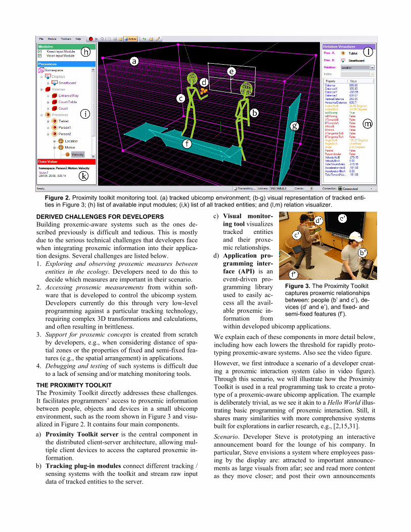
Figure 2. Proximity toolkit monitoring tool. (a) tracked ubicomp environment; (b-g) visual representation of tracked enti-ties in Figure 3; (h) list of available input modules; (i,k) list of all tracked entities; and (l,m) relation visualizer.
Figure 3. The Proximity Toolkit captures proxemic relationships between: people (b’ and c’), de-vices (d’ and e’), and fixed- and semi-fixed features (f’).
(typed into their mobile phones) by touching the phone against the screen. To create a seamless experience for in-teracting with the large ambient display, Steve plans to recognize nearby people and their mobile devices. Steve builds his prototype to match the room shown in Figure 3.
Proximity Toolkit Server The Proximity Toolkit Server is the central component managing proxemic information. It maintains a hierarchical data model of all fixed features (e.g., walls, entranceways), semi-fixed features (e.g., furniture, large displays), and mobile entities (e.g., people or portable devices). This model contains basic information including identification, position in 3D coordinates, and orientation. The server and toolkit API then perform all necessary 3D calculations on this data required for modeling information about higher-level proxemic relationships between entities.
The server is designed to obtain raw data from various at-tached tracking systems. For flexibility, each of the track-ing systems is connected through a separate plugin module loaded during the server’s start-up. These plugins access the captured raw input data and transfer it to the server’s data model. The current version of our toolkit contains two plugins: the marker-based VICON motion capturing system, which allows for sub-millimeter tracking accuracy [www.vicon.com], and the KINECT sensor, which allows tracking of skeletal bodies [www.kinect.com]. In a later sec-tion we discuss the implementation, integration, and com-bination of these tracking technologies, and how to setup the server to match the environment. Importantly, the serv-er’s unified data model is the basis for a distributed Model-View-Controller architecture [3], which in turn is used by the toolkit client API, the monitoring tool, and to calculate proxemic relationships between entities.
Scenario. Developer Steve begins by starting the server. The server automatically loads all present tracking plugins. Based on the information gathered from these plugins, it populates and updates the unified data model in real-time. By default, our toolkit already includes a large pre-configured set of tracked entities with attached markers (such as hats, gloves, portable devices) and definitions of fixed and semi-fixed features (large interactive surface, surrounding furniture). To add a new tracked object, Steve attaches markers to it and registers the marker configura-tion as a new tracked entity. This process takes minutes.
Visual Monitoring Tool: Tracked Entities The visual monitoring tool helps developers to see and un-derstand what entities are being tracked and how the data model represents their individual properties. Figure 2 is a screenshot of this tool: the visualized entities in (b-f) corre-spond to real-world entities captured in Figure 3 (b’-f’).
Specifically, the visual monitoring tool connects to the server (through TCP) and presents a 3D visualization of the data model (Figure 2 centre). This view is updated in real-time and always shows: the approximate volume of the tracked space as a rec-
tangular outline box (Fig. 2a) position and orientation of people (Fig. 2bc) portable digital devices, such as a tablet pc (Fig. 2d) digital surfaces, such as the large wall display (Fig. 2e) fixed and semi-fixed features, such as a table, couch
(Fig. 2f), and entranceway (Fig. 2g).
The left side of the monitoring window shows a list of the activated input tracking plugins (Figure 2h) and another list with an overview of all currently tracked entities (Figure 2i). Clicking on any of the items in this list opens a hierar-
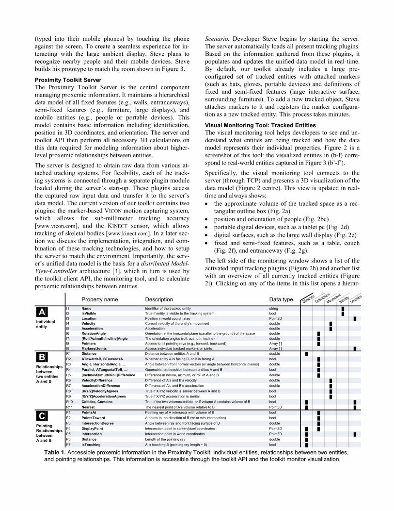
Property name Description Data type
.A.Individual entity
I1 Name Identifier of the tracked entity string █I2 IsVisible True if entity is visible to the tracking system bool █I3 Location Position in world coordinates Point3D █I4 Velocity Current velocity of the entity’s movement double █I5 Acceleration Acceleration double █I6 RotationAngle Orientation in the horizontal plane (parallel to the ground) of the space double █I7 [Roll/Azimuth/Incline]Angle The orientation angles (roll, azimuth, incline) double █I8 Pointers Access to all pointing rays (e.g., forward, backward) Array [ ] █I9 Markers/Joints Access individual tracked markers or joints Array [ ] █
.B.Relationships between two entitiesA and B
R1 Distance Distance between entities A and B double █
R2 ATowardsB, BTowardsA Whether entity A is facing B, or B is facing A bool █
R3 Angle, HorizontalAngle, ... Angle between front normal vectors (or angle between horizontal planes) double █
R4 Parallel, ATangentalToB, ... Geometric relationships between entities A and B bool █
R5 [Incline/Azimuth/Roll]Difference Difference in incline, azimuth, or roll of A and B double █
R6 VelocityDifference Difference of A’s and B’s velocity double █
R7 AccelerationDifference Difference of A’s and B’s acceleration double █
R8 [X/Y/Z]VelocityAgrees True if X/Y/Z velocity is similar between A and B bool █
R9 [X/Y/Z]AccelerationAgrees True if X/Y/Z acceleration is similar bool █
R10 Collides, Contains True if the two volumes collide, or if volume A contains volume of B bool █ █
R11 Nearest The nearest point of A’s volume relative to B Point3D █ █
.C.Pointing Relationships between A and B
P1 PointsAt Pointing ray of A intersects with volume of B bool █
P2 PointsToward A points in the direction of B (w/ or w/o intersection) bool █
P3 IntersectionDegree Angle between ray and front facing surface of B double █
P4 DisplayPoint Intersection point in screen/pixel coordinates Point2D █ █
P5 Intersection Intersection point in world coordinates Point3D █ █
P6 Distance Length of the pointing ray double █
P7 IsTouching A is touching B (pointing ray length ~ 0) bool █ Table 1. Accessible proxemic information in the Proximity Toolkit: individual entities, relationships between two entities, and pointing relationships. This information is accessible through the toolkit API and the toolkit monitor visualization.

chical list of properties showing the item’s current status (e.g., its location, or orientation). When Steve selects any of these properties, the monitoring window shows the cor-responding value (e.g., the current position as a 3D Vector, or the velocity; Fig 2k). Part A of Table 1 shows an over-view of the most important available properties.
Scenario. Before Steve starts to program, he explores all available proxemic information through the visual monitor-ing tool. He inspects the currently tracked entities (Figure 2 left, also displayed in the center), as well as which entity properties are available for him to use. Steve finds this visu-al overview particularly important to his initial design, as he is still investigating the possible mappings of proxemic rela-tionship to system behaviour. In later stages, he will also use this monitoring tool to test and debug his program.
Visual Monitoring Tool: Relationships Another major feature of the visual monitoring tool is to let people set and observe particular proxemic relationships between entities, where developers will use these relation-ships to define particular proxemic interaction behaviours. Specifically, the Relation Visualizer panel (Fig. 2, l-m) al-lows a developer to select a type of relationship between entities, and then to observe the values of all related proper-ties. The complete list of proxemic relationships that are available to observe are summarized in part B/C of Table 1.
Scenario. Steve wants to observe a relationship between Per-son1 (representing the first person entering the space) and the Smartboard display. Steve drags the two entries from the list of tracked entities (Fig. 2i) to the top of the Relation Visual-izer panel (Fig. 2l). Next, Steve selects one of the following relationship categories from a drop down menu.
Orientation (e.g., angles between entities) Location (e.g., changes in distance between the person
and the smartboard) Direction (e.g., if the front of the person’s body faces
towards the screen) Movement (e.g., acceleration or velocity) Pointing (e.g., the display intersection point of the right
arm pointer of the person) Collision (e.g., if the volumes of two tracked entities
are so close that they collide)
Steve can now observe how those entities relate to each other. The panel in Fig. 2m shows the numeric values of any properties belonging to this category. The categories plus the properties within them operationalize the five es-sential elements of proximity mentioned previously.
With his public announcement application in mind, Steve is interested in knowing when a person is in close distance to the display. He selects the Location category, and looks at the values of the Distance property, which – in this case – measures the distance of the person’s body to the board (Fig. 2m). Next, he wants to know when the person is fac-ing towards the screen. He selects the Direction category from the menu, and immediately sees the related proxemic
properties with their current values and their graphical appearance in the visualization. He is particularly interested in the ATowardsB prop-erty, which is true if the person [A] is facing towards the smartboard [B]. He decides to use the infor-mation about direction and distance to adapt the content shown on the announcement board.
Steve continues exploring other proxemic relationship categories and makes note of the types of rela-tionships that he will integrate into his application. As he selects these other categories (Fig. 2l), the 3D visual representation changes ac-cordingly. Figure 4 illustrates three other visualizations of proxemic relationships that Steve explored: the distance between the person and the display (Fig. 4a), the forward pointer of the left arm and its inter-section point with the smartboard (Fig. 4b), and the collision volumes (Fig. 4c).
SIMPLIFIED API ACCESS TO PROXEMIC INFORMATION We now take a closer look at the development API, offered via an object-oriented C# .NET development library. We designed it to be fairly easy to learn and use (1) by taking care of and hiding low-level infrastructure details and (2) by using a conventional object-oriented and event-driven programming pattern. Essentially, the API lets a developer programmatically access the proxemic data previously ob-served in the monitoring tool. We explain how this works by continuing our scenario.
Scenario. Steve adds the Proximity Toolkit API library to his own PC-based software project. The only criterion is that his PC needs network access to the proximity server. Steve begins by initializing his software. To set up his software to use the server, he adds three lines of code (lines 1-3 in Figure 5). First, he creates a new client connection object, then starts the connection to the server (at the given IP address and port), and finally creates a ProximitySpace object, which provides a high-level framework for monitor-ing the interaction of tracked presences, such as people and objects. The ProximitySpace object maintains a list of all available tracked entities, and is used to create instances of entities or for initializing event handlers to monitor rela-tionships. Next, Steve initializes three of the entities he is interested in (lines 4-6): the person representing the first person entering the space, the smartboard, and a tablet (PresenceBase is a special object that represents individual tracked or static objects).
Figure 4. Visualizing proxemic relation-ships: (a) distance, (b) pointing and (c) collision.

The following describes how Steve then monitors the rela-tionships between these entities. We go through each of the five proxemic dimensions introduced earlier (albeit in a slightly different order), explaining how Steve writes his application to monitor changes in each of these dimensions, and how he uses that information to mediate interaction with his interactive announcement board.
1. Orientation
Monitoring orientation changes allows (1) accessing the exact angle of orientation be-tween two entities and/or (2) determining whether two entities are facing each other. Steve is mostly interested in the relationship between a person and the smartboard display. He adds line 7, which creates a relationship between these two as indi-cated by their parameters. The system is now tracking both entities relative to each other. Steve is also interested in knowing when the orientation and location between these two changes. For orientation, he initializes an event handler to receive updates of the Direction relationship between the person and the smartboard (line 8). The OnDirectionUpdat‐ed method is invoked when the system recognizes any changes in orientation between the person and the smart-board (line 10). While Steve could access each entity’s precise orientation values (e.g., angles of orientation), he is only really interested in knowing whether a person is fac-ing towards the smartboard. Consequently, he writes the event handler callback method (lines 10-12) to access the ATowardsB property in the event arguments: it is true if the person is facing the smartboard (line 11).
Entries R2-R5 and P1-P3 in Table 1 give an overview of further orientation relationships that can be monitored. As well, the programmer can access the absolute orientation of an individual entity at any time (see entries I6 – I7 in Table 1). For example, the following property returns the current yaw angle of the tablet: tablet.Orientation.Yaw;
2. Distance, including Location, Pointing and Touching
Similarly, Steve can monitor changes of dis-tance between entities. We illus-trate how Steve can receive updates about distance changes by adding another event callback for OnLocationUpdated events (line 9). This callback method (line 13-15) is invoked whenever the location of at least one of the two entities changes. In line 14 Steve ac-cesses the current distance be-tween the person and the
smartboard, and uses this distance value to make the visual content on the announcement board vary as a function of the distance between the person and the display. The closer the person, the more content is revealed.
Other available properties relate to distance. First, the actual location property of each entity, i.e, its position within the space, is accessible at any time. For example Steve can ac-cess the current coordinates of the person by accessing this.person.Location. Second, pointing relationships moni-tor orientation and distance simultaneously. Pointing is simi-lar to ray-casting. Each entity can have one or multiple point-ers. Each pointer has a pointing direction, and the callback returns the intersection of that direction with the other entity. It also returns the length of the pointing ray between entities, which may not be exactly the same as distance. To illustrate, Steve tracks not only the close distance of a tablet computer to the smartboard, but where that tablet raycasts onto the smartboard. He initializes a second RelationPair between the tablet and the smartboard (line 16). He subscribes for OnPointingUpdated events that are triggered whenever any of the pointers of the tablet changes relative to the board (line 17). In the event callback method (lines 18 to 22) Steve first checks if the tablet’s forward pointer faces the display (PointsTowards) and if the ray length between tablet and board is smaller than 50 cm (line 19). If this is the case, he shows an icon on the ray’s intersection point (line 20) on the smartboard to let the person know they can touch the surface to initiate a transfer.
Third, Steve checks if the tablet is touching the surface - (IsTouching, line 21) – a distance of ~0. If so, he initiates transfer of the content on the tablet to the large display. By using the intersection point of the tablet with the screen Steve can show the transferred content at the exact position where the tablet touches the board.
01 ProximityClientConnection client = new ProximityClientConnection();02 client.Start("192.168.0.11", 888);
03 ProximitySpace space = client.GetSpace();04 PresenceBase person = space.GetPresence("Person1");05 PresenceBase smartboard = space.GetDisplay("SmartBoard");06 PresenceBase tablet = space.GetDisplay("Tablet");
07 RelationPair relation = space.GetRelationPair(person, smartboard);08 relation.OnDirectionUpdated += new DirectionRelationHandler(OnDirectionUpdated);09 relation.OnLocationUpdated += new LocationRelationHandler(OnLocationUpdated);
10 void OnDirectionUpdated(ProximitySpace space, DirectionEventArgs args) {11 if (args.ATowardsB) { [... person is facing the display, show content ...] } else { [...hide…] }12 }13 void OnLocationUpdated(ProximitySpace space, LocationEventArgs args) {14 double distance = args.Distance; [... change visual content as a function of distance ...]15 }
16 RelationPair relationTablet = space.GetRelationPair(tablet, smartboard);17 relationTablet.OnPointingUpdated += new PointingRelationHandler(OnPointingUpdated);
18 void OnPointingUpdated(ProximitySpace space, PointingEventArgs args) {19 if (args["forward"].PointsToward && (args["forward"].Distance < 500.0)) {20 Point intersection = args["forward"].DisplayPoint;
[... show awareness icon on smartboard display ...]21 if (args["forward"].IsTouching) {
[... transfer content from the tablet to the large display ...]22 }}}
Even
tsC
allbac
ksC
allback
Setu
pE
vent
Figure 5. Partial source code for the proxemic-aware announcement board application.

3. Identity
The toolkit allows access to the identity in-formation of all tracked entities. The Name property provides the identifier string of each entity, and IsVisible is true if the entity is currently tracked by the system. A developer can subscribe to events notifying about any new tracked entities that enter the ubicomp space through the space.OnPresenceFound event. In the associated event callback method, the event argu-ments give information about the type and name of the detected entity. For example, Steve could have his system track and greet a previously unseen person with a splash screen on first appearance, and dynamically initialize any necessary event callbacks relating that person to other enti-ties in a scene.
4. Motion
Motion events describe the changes of dis-tance and orientation over time, e.g., to receive updates of changes in acceleration and veloci-ty of any entity. For example, Steve can have his application ignore people moving quickly by the display, as he thinks they may be annoyed by any attempts to attract their attention. To receive such velocity updates, Steve would add an event handler (similar to lines 8 and 9) through OnMotionUpdated and then simply access the value of the args.Velocity property. Based on that val-ue, he would activate the display only if the velocity was less than a certain threshold. Of course, Steve could have determined a reasonable threshold value by observing the velocity value of a person rushing by the display in the visual monitoring tool.
5. Location: Setup of Environment
Using location, the toolkit lets one track the relationships of people and devices to the semi-fixed and fixed features in the physical environment. For example, the model may contain the fixed-feature position of the en-tranceway to a room, allowing one to know if someone has crossed that threshold and entered the room. It may also contain the location of semi-fixed features, such as the chairs and table seen in Figure 3. Monitoring event han-dlers for fixed and semi-fixed features can be initialized similarly to the ones we defined earlier.
Steve sets up several fixed feature entities – the smartboard and the entrance-way – through several initial configura-tion steps. This only has to be done once. Using a physical pointer (the stick in Figure 6a), he defines each entity’s volume by physically outlining them in space. Under the covers, the toolkit tracks the 3D tip location of this stick and builds a 3D model of that entity. Each location point of the model is confirmed by pressing a button (e.g., of a wirelessly connected mouse). Figure 6 illustrates how Ste-ve defines the smartboard. After placing the pointer in the four corners of the display plane (Fig. 6a), the coordinates appear in the visualization (6b), and a control panel allows fine adjustments. He saves this to the Proximity Toolkit
server as a model. Simi-larly, Steve defines the entrance-way by outlin-ing the door (Fig. 2g), and the couch by outlin-ing its shape (Fig. 2f). Steve can now monitor proxemic relationships between all moving enti-ties and these new de-fined features. For ex-ample, he can create an event handler to receive notifications when a per-son passes through the entrance-way (by using the OnCollisionUpdated event) and when a person sits on the couch (using the Distance property of the OnLocationUpdated).
Semi-fixed features differ. While they are part of the envi-ronment, they are also movable. As with fixed features, a developer would model a shape by outlining it with the stick. Unlike fixed features, he would also add markers to that entity. The toolkit tracks those markers, and reposi-tions the entity accordingly. For example, Steve could have modeled a chair, tracked where it is in the room, and ad-justed the presentation if a person was sitting on it.
We should also mention that we believe location should also include further contextual information about this par-ticular environment, e.g., the meaning of that place. Such contextual information is not yet included in the toolkit, but could be easily added as metadata.
Scenario – next steps. Our walkthrough example illustrated the easy-to-use mechanisms of integrating proxemic meas-urements into a ubicomp system. While simple, this start-ing point allows Steve to further extend the system func-tionality exploring proxemic interactions. Examples in-clude: (1) subscribing to events of a second person to let the system react to both persons’ movement to the display. (2) Monitoring additional tablet computers, and enabling content-sharing between them as a function of the device’s distance. Overall, the toolkit minimizes the effort neces-sary for such extensions, and allows rapid exploration and alteration of interaction techniques.
Additional Tools Facilitating Prototyping Process The toolkit is more than an API, as it offers additional tools to lower the threshold for developing proxemic-aware sys-tems. The already-discussed visual monitoring tool is one of these. Several others are described below.
Recording and playback of proxemic sequences. To test applications, developers would need actors to perform the proxe-mic movements between entities every time. This is prob-lematic for many reasons: it is tedious; the sensing equipment may not be available; and it is difficult to repeat particular test sequences. To alleviate this, the toolkit provides a rec-
Figure 6. Defining new fixed and semi-fixed features (e.g., display) using a tracked physical pointer (a) and visual feedback (b).
ord/playback tool within the visual monitoring tool. With the click of a button, developers can record events generated by entities moving in the environment. They can later play back these sequences for testing. Under the covers, each individu-al sequence is recorded as an XML file, where the toolkit uses that record to recreate all events. Because the tracking hardware is not needed during playback, testing can be done anywhere, e.g., a desktop workstation located elsewhere. For example, Steve could have recorded test sequences such as: a person passing by the screen, a person approaching the dis-play, or a device pointing towards the display. He would then replay these sequences while developing and testing his software at his desk.
Component library, templates, and examples. We lever-age developers’ existing practices by seamlessly integrating the toolkit into the familiar capabilities of a popular IDE, Microsoft Visual Studio (but our ideas are generalizable to other IDEs). First, the toolkit includes a library of drag-and-drop components (compatible with both WPF and Windows Forms), where the programmer can view and set all their properties and generate event handlers for all available events via direct manipulation rather than coding. This not only reduces tedium and coding errors, but also reduces the threshold for inexperienced developers (such as students) as all properties and events are seen. Second, we reduce start-up effort by including a set of templates con-taining the minimum required code. Third, to ease learning, we provide a large set of teaching applications illustrating standard programming patterns. Using a very simple exam-ple, each of them illustrates the code required to implement a particular proxemic relationship.
FLEXIBLE AND EXTENSIBLE ARCHITECTURE Our first version of the toolkit [5] was tightly linked to a particular tracking technology. This means that other tech-nologies could not be exploited. The toolkit’s current version decouples the API from underlying tracking technologies.
Plugin architecture. The data providers of raw tracking input data are implemented as separate plugin modules, which are dynamically loaded into the proximity server at start-up. We currently have plugins for two different track-ing technologies – the VICON motion capturing system that tracks infrared reflective markers, and the Microsoft KINECT depth camera). We anticipate a variety of further plugins for tracking systems (e.g., other IR tracking).
Templates, base classes, interfaces, and utility classes facili-tate plugin development. Programmers begin with the plugin template, derived from the Plugin base class. This base class provides a set of utility methods, such as one for affine trans-formations from the tracking system’s local coordinate sys-tem to the Proximity Toolkit’s unified coordinate system. This affine matrix is calculated through a simple one time calibration process. Next, developers implement several mandatory methods, including OnStartup (to start and initial-ize tracking hardware) and OnClose (to stop tracking hard-ware). In our two plugin implementations, the OnStartup
method causes the VICON plugin to initialize the underlying NEXUS software [30], and the KINECT plugin to initialize the OPENNI [24] software. Once initialized, plugins receive raw data of tracked people, objects, and/or devices in 3D space. The OnUpdate method of each plugin module is re-sponsible to stream raw tracking data into the toolkit.
Diverse tracking capabilities. In order to allow the integra-tion of hardware with different tracking capabilities, the plugins specify the kinds of proxemic information they sup-port. For example, a tracking system might gather infor-mation about the position of an entity, but not its orientation. Following the decorator pattern [7], each plugin can specify exactly what kind of input data a particular tracking hard-ware provides. The decorator pattern describes a mechanism to extend the functionality of objects at run-time. In our case, the plugin creates decorator objects for each proxemic di-mension of input data it supports and calls the update method on these decorators. For example, the LocationDecorator updates location of an entity and the OrientationDecorator its orientation (plugins can add custom decorators for any proxemic information not yet supported by available decora-tors). During each update cycle (i.e., when OnUpdate is called), the decorator objects update the proxemic infor-mation in the server’s unified data model as proxemic in-formation of each entity. No high-level calculations on raw input data are required for the plugin implementation, as the-se are performed by the proximity server or API.
The available dimensions of input data for each tracked enti-ty are directly visible in the monitoring tool: a list view and 3D view give direct feedback about the available proxemic dimensions. These dimensions can be also checked from the client API by using the IsVisible properties for each availa-ble input dimension.
Distributed data model. The server’s unified data model is a collection of hierarchical key-value pairs representing all currently tracked entities. The keys are structured ac-cording to the following pattern: /[space]/[presence]/[proxemic‐dimension]/[identifier]
For example, the following key-value pairs are part of the data model of a tracked person (i.e., location, motion, and orientation): /home/person/locationdecorator/location = [12.4,3.7,8.2] /home/person/motiondecorator/velocity = [0.1,0.6,20.5] /home/person/orientationdecorator/rollangle = ‐95.5
This data model is implemented through a shared hash ta-ble that is accessible through TCP connections [3]. Thus, the data model is accessible from all computers linked in the same network. Usually the underlying data model is hidden from developers (though they can access and modi-fy it if desired). The server and the toolkit API calculate necessary proxemic relationships for the entities present in the data model. To reduce computational overhead, the necessary 3D calculations are done only on demand, i.e., when a client subscribes to events for a particular relation-ship between two entities.
Substitution. Tracking systems/plugins can be substituted, providing that their hardware gathers similar tracking infor-mation. For example, instead of using the depth camera for tracking people’s positions and postures, a programmer can use the IR motion capture system instead by attaching IR re-flective markers to a person’s body. Due to the separation of tracking hardware and API, a programmer’s access to this proxemic information via the toolkit API remains unchanged, regardless of the underlying tracking mechanism used.
Uncertainty. All 3D tracking systems provide input with some kind of uncertainty. As tracking systems differ in precision of tracking data they provide, plugins are re-quired to provide additional information about this uncer-tainty of tracking information. In particular, two values describe tracking uncertainty in our toolkit. First, the Pre‐cision value specifies how accurate the system tracks enti-ties (normalized between 0.0 and 1.0). Precision is defined as 1 / [minimum resolution], where the minimum resolu-tion is measured in mm (e.g., minimum resolution is 1mm for the VICON system, and 20mm for KINECT). Thus, the lower the resolution, the higher the precision value is. Se-cond, the Confidence value indicates the estimated accuracy of the provided tracking information. It ranges from 0.0-1.0, where 0 is 0% confidence (i.e., lost tracking), and 1 is 100% confidence. In our plugins, the VICON motion captur-ing system provides estimated accuracy information for all tracked markers, and this value is mapped directly to our Confidence value. In contrast, the Confidence value of a person tracked by the OPENNI depth cameras is calculated by dividing the recognized parts of the body (e.g., arms, legs) to the total number of possible parts to recognize (i.e., the Confidence is 1.0 if the full body of a person is tracked). These confidence and precision values are applied to each individually tracked entity. Furthermore, the precision val-ue can differ depending on where in the 3D space an entity is tracked (e.g., precision is higher when a person stands closer to the depth sensing camera).
A developer can monitor the quality of input data with the visual monitor tool. A table view lists confidence and pre-cision values, and the 3D view gives direct feedback of the precision (or absence) of tracking. Similarly, the API ex-poses the Confidence and Precision values of each entity. It also includes the IsVisible (false if lost tracking) and LastUpdated (timestamp of the last update) properties.
Combination. In cases where different plugins provide complementary tracking information of a single entity, the information can be combined in the proximity server’s data model. For example, the KINECT and VICON systems could both track a single person simultaneously: the KINECT sys-tem provides information about the person’s body position in 3D space, and the VICON system tracks a glove the person is wearing in order to retrieve fine-grained information of the person’s finger movements. Both plugins then update the entity’s data model in the server with their tracked infor-mation. If two systems provide overlapping/conflicting track-ing data (e.g., two systems provide information about an
entity’s location), the information will be merged in the serv-er’s data model. To do so, the server calculates a weighted average (taking the Confidence and Precision values) of all values received in a certain time frame (i.e., one update cycle) and updates the proxemic data model of that entity. This means, that the higher the confidence and precision value of a given entry, the more it affects the final merged value of that entity.
Alternatively, other algorithms for tracking data fusion (e.g., [33]) could be seamlessly implemented on the server level (thus not requiring any changes to the plugins or the API). We could also extend the toolkit’s uncertainty infor-mation via Schwarz et al.’s [27] framework for handling ambiguous input, where this could track ambiguous infor-mation simultaneously and delay event triggers.
Availability. Our toolkit including software and documenta-tion facilitating development of custom plugins (or other possible extensions to the toolkit) are available as open source on the GroupLab Proximity Toolkit website [10].
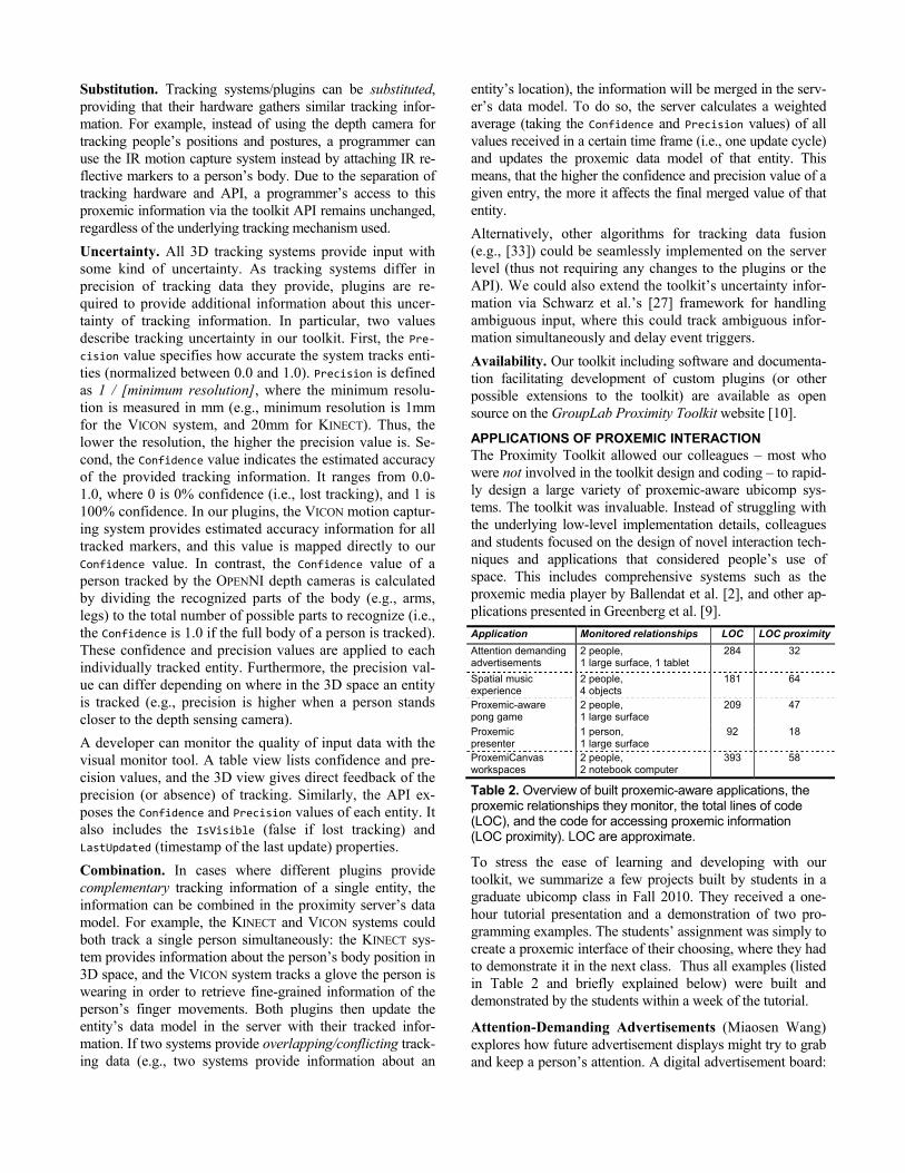
APPLICATIONS OF PROXEMIC INTERACTION The Proximity Toolkit allowed our colleagues – most who were not involved in the toolkit design and coding – to rapid-ly design a large variety of proxemic-aware ubicomp sys-tems. The toolkit was invaluable. Instead of struggling with the underlying low-level implementation details, colleagues and students focused on the design of novel interaction tech-niques and applications that considered people’s use of space. This includes comprehensive systems such as the proxemic media player by Ballendat et al. [2], and other ap-plications presented in Greenberg et al. [9].
Application Monitored relationships LOC LOC proximity
Attention demanding advertisements
2 people, 1 large surface, 1 tablet
284 32
Spatial music experience
2 people, 4 objects
181 64
Proxemic-aware pong game
2 people, 1 large surface
209 47
Proxemic presenter
1 person, 1 large surface
92 18
ProxemiCanvas workspaces
2 people, 2 notebook computer
393 58
Table 2. Overview of built proxemic-aware applications, the proxemic relationships they monitor, the total lines of code (LOC), and the code for accessing proxemic information (LOC proximity). LOC are approximate.
To stress the ease of learning and developing with our toolkit, we summarize a few projects built by students in a graduate ubicomp class in Fall 2010. They received a one-hour tutorial presentation and a demonstration of two pro-gramming examples. The students’ assignment was simply to create a proxemic interface of their choosing, where they had to demonstrate it in the next class. Thus all examples (listed in Table 2 and briefly explained below) were built and demonstrated by the students within a week of the tutorial.
Attention-Demanding Advertisements (Miaosen Wang) explores how future advertisement displays might try to grab and keep a person’s attention. A digital advertisement board:
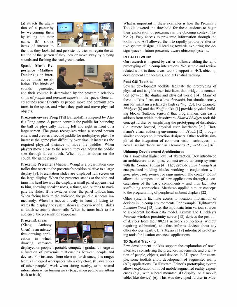
(a) attracts the atten-tion of a passer-by by welcoming them by calling out their name; (b) shows items of interest to them as they look; (c) and persistently tries to regain the at-tention of that person if they look or move away by playing sounds and flashing the background color.
Spatial Music Ex-perience (Matthew Dunlap) is an inter-active music instal-lation. The kinds of sounds generated and their volume is determined by the proxemic relation-ships of people and physical objects in the space. Generat-ed sounds react fluently as people move and perform ges-tures in the space, and when they grab and move physical objects.
Proxemic-aware Pong (Till Ballendat) is inspired by Ata-ri’s Pong game. A person controls the paddle for bouncing the ball by physically moving left and right in front of a large screen. The game recognizes when a second person enters, and creates a second paddle for multiplayer play. To increase the game play difficulty over time, it increases the required physical distance to move the paddles. When players move close to the screen, they can adjust the paddle size through direct touch. When both sit down on the couch, the game pauses.
Proxemic Presenter (Miaosen Wang) is a presentation con-troller that reacts to the presenter’s position relative to a large display [9]. Presentation slides are displayed full screen on the large display. When the presenter stands at the side and turns his head towards the display, a small panel appears next to him, showing speaker notes, a timer, and buttons to navi-gate the slides. If he switches sides, the panel follows him. When facing back to the audience, the panel disappears im-mediately. When he moves directly in front of facing to-wards the display, the system shows an overview of all slides as touch-selectable thumbnails. When he turns back to the audience, the presentation reappears.
ProxemiCanvas (Xiang Anthony Chen) is an interac-tive drawing appli-cation in which drawing canvases displayed on people’s portable computers gradually merge as a function of proxemic relationships between people and devices. For instance, from close to far distance, this ranges from: (a) merged workspaces when very close, (b) awareness of other people’s work when sitting nearby, to no shared information when turning away (e.g., when people are sitting back to back).
What is important in these examples is how the Proximity Toolkit lowered the threshold for these students to begin their exploration of proxemics in the ubicomp context (Ta-ble 2). Easy access to proxemic information through the toolkit and API allowed them to rapidly prototype alterna-tive system designs, all leading towards exploring the de-sign space of future proxemic-aware ubicomp systems.
RELATED WORK Our research is inspired by earlier toolkits enabling the rapid prototyping of ubicomp interactions. We sample and review related work in three areas: toolkit support in HCI, ubicomp development architectures, and 3D spatial tracking.
Post-GUI Toolkits Several development toolkits facilitate the prototyping of physical and tangible user interfaces that bridge the connec-tion between the digital and physical world [14]. Many of these toolkits focus on a low threshold, but simultaneously aim for maintain a relatively high ceiling [23]. For example, Phidgets [8] and the iStuff toolkit [1] provide physical build-ing blocks (buttons, sensors) that programmers can easily address from within their software. Shared Phidgets took this concept further by simplifying the prototyping of distributed (i.e. remote located) physical user interfaces [21]. Hart-mann’s visual authoring environment in dTools [12] brought similar concepts to interaction designers. Other toolkits sim-plified the integration of computer vision techniques into novel user interfaces, such as Klemmer’s PapierMache [16].
Ubicomp Development Architectures On a somewhat higher level of abstraction, Dey introduced an architecture to compose context-aware ubicomp systems with the Context Toolkit [4]. They provide context widgets as encapsulated building blocks, working in conjunction with generators, interpreters, or aggregators. The context toolkit allows the composition of new applications through a con-catenation of the basic components – and thus facilitates scaffolding approaches. Matthews applied similar concepts to the programming of peripheral ambient displays [22].
Other systems facilitate access to location information of devices in ubicomp environments. For example, Hightower’s Location Stack [13] fuses the input data from various sources to a coherent location data model. Krumm and Hinckley’s NearMe wireless proximity server [18] derives the position of devices from their 802.11 network connections (without requiring calibration), and thus informs devices about any other devices nearby. Li’s Topiary [19] introduced prototyp-ing tools for location-enhanced applications.
3D Spatial Tracking Few development toolkits support the exploration of novel interfaces considering the presence, movements, and orienta-tion of people, objects, and devices in 3D space. For exam-ple, some toolkits allow development of augmented reality (AR) applications. To illustrate, Feiner’s prototyping system allows exploration of novel mobile augmented reality experi-ences (e.g., with a head mounted 3D display, or a mobile tablet like device) [6]. This was developed further in Mac-

Intyre’s DART [20], Open Tracker [25], and Sandor’s proto-typing environment [26] for handheld-based AR applica-tions. These toolkits mostly focus on supporting augmented reality applications running on mobile devices, and not on ubicomp ecologies in small rooms. Some commercial sys-tems track 3D data of objects. For example, the VICON Nex-us software gives access to 3D spatial information of tracked objects. This information, however, only includes low level position data, which developers need to process manually in order to gain insights into proxemic relationships.
Our Proximity Toolkit builds on this prior work. Like post-GUI toolkits, it bridges the connection between the virtual and real world, but in this case by tracking proxemic in-formation. Similarly, it extends ubicomp architectures and 3D spatial tracking by capturing and providing fine-grained information about 3D proxemic relationships in small ubicomp spaces (i.e., not only location, but also orientation, pointing, identity, etc.). Like the best of these, it supplies an API that, in our case, makes the five essential proxemic dimensions [9] easily accessible to developers. Like the more advanced tools, it also provide additional develop-ment tools, such as a monitoring tool for visualizing prox-emic relationships, a record/playback tool to simplify test-ing; templates, documentation, examples, and so on.
CONCLUSION The Proximity Toolkit enables rapid prototyping and ex-ploration of novel interfaces that incorporate the notion of proxemic relationships. Through hiding most of the under-lying access to tracking hardware and complex 3D calcula-tions, our toolkit lets developers concentrate on the actual design and exploration of novel proxemic interaction.
We invite other researchers to use it. The Proximity Toolkit is available as open source [10].
ACKNOWLEDGMENTS This research is partially funded by the iCORE/NSERC/ SMART Chair in Interactive Technologies, Alberta Innovates Technology Futures, NSERC, and SMART Technologies Inc.
REFERENCES 1. Ballagas, R., Ringel, M., Stone, M., and Borchers, J. iStuff:
a physical user interface toolkit for ubiquitous computing environments. Proc. of CHI'03, ACM (2003).
2. Ballendat, T., Marquardt, N., and Greenberg, S. Proxemic Interaction: Designing for a Proximity and Orientation-Aware Environment. Proc. of ITS'10, ACM (2010).
3. Boyle, M. and Greenberg, S. Rapidly prototyping multime-dia groupware. Proc. of DMS, Knowl. Sys. Institute, (2005).
4. Dey, A.K., et al. A conceptual framework and a toolkit for supporting the rapid prototyping of context-aware applica-tions. Hum.-Comp. Int. 16, 2, L. Erlbaum (2001), 97-166.
5. Diaz-Marino, R. and Greenberg, S. The proximity toolkit and ViconFace: the video. Ext. Abst. CHI '10, ACM (2010).
6. Feiner, S., et al. A touring machine: Prototyping 3D mobile augmented reality systems for exploring the urban environ-ment. Personal Technologies 1, 4 (1997), 208-217.
7. Gamma, E., et al. Design Patterns: Elements of Reusable Object-Oriented Software. Addison-Wesley, 1994.
8. Greenberg, S. and Fitchett, C. Phidgets: Easy Development of Physical Interfaces Through Physical Widgets. Proc. of UIST'01, ACM (2001), 209–218.
9. Greenberg, S., Marquardt, N., et al. Proxemic interactions: the new ubicomp? interactions 18, ACM (2011), 42–50.
10. GroupLab. Proximity Toolkit website, http://grouplab.cpsc. ucalgary.ca/proximitytoolkit, Retrieved July 5, 2011.
11. Hall, E.T. The Hidden Dimension. Doubleday, N.Y, 1966. 12. Hartmann, B., et al. Reflective physical prototyping through
integrated design, test, and analysis. Proc. UIST, ACM (2006). 13. Hightower, J., et al. The location stack: A layered model for
location in ubiquitous computing. Proc. of WMCSA'02, (2002). 14. Ishii, H. and Ullmer, B. Tangible Bits: Towards Seamless
Interfaces Between People, Bits and Atoms. Proc. of CHI'97, ACM (1997), 234–241.
15. Ju, W., et al. Range: exploring implicit interaction through electronic whiteboard design. Proc. of CSCW'08, ACM (2008).
16. Klemmer, S.R., et al. Papier-Mache: Toolkit Support for Tangible Input. Proc. of CHI'04, ACM (2004), 399–406.
17. Kortuem, G., et al. Sensing and visualizing spatial relations of mobile devices. Proc. of UIST'05, ACM (2005), 93-102.
18. Krumm, J. and Hinckley, K. The NearMe wireless proximity server. Lecture notes in computer science, (2004), 283-300.
19. Li, Y., et al. Topiary: a tool for prototyping location-enhanced applications. Proc. of UIST '04, ACM (2004).
20. MacIntyre, B., et al. DART: a toolkit for rapid design explo-ration of augmented reality experiences. Proc. of UIST'04, ACM (2004).
21. Marquardt, N. and Greenberg, S. Distributed Physical Inter-faces with Shared Phidgets. Proc. of TEI'07, ACM (2007).
22. Matthews, T., et al. A toolkit for managing user attention in peripheral displays. Proc. of UIST '04, ACM (2004).
23. Myers, B.A., et al. Past, Present, and Future of User Inter-face Software Tools. TOCHI 7, 1, ACM (2000), 3–28.
24. PrimeSense. OpenNI SDK, http://www.openni.org, Accessed July 5, 2011.
25. Reitmayr, G. et al. OpenTracker: A flexible software design for three-dimensional interaction. Virt. Reality 9, (2005).
26. Sandor, C. and Klinker, G. A rapid prototyping software infrastructure for user interfaces in ubiquitous augmented reality. Pers. and Ubiq. Comp. 9, (2005).
27. Schwarz, J., et al. A framework for robust and flexible han-dling of inputs with uncertainty. Proc of UIST, ACM (2010).
28. Snibbe, S.S. et al. Social immersive media: pursuing best practices for multi-user interactive camera/projector exhib-its. Proc. of CHI '09, ACM (2009), 1447–1456.
29. Streitz, N., et al. Ambient displays and mobile devices for the creation of social architectural spaces. In Public and Sit-uated Displays. Kluwer, 2003, 387-410.
30. Vicon Motion Systems. Nexus software, http://www.vi-con.com/products/nexus.html, Retrieved July 5, 2011.
31. Vogel, D. et al. Interactive public ambient displays: transi-tioning from implicit to explicit, public to personal, interac-tion with multiple users. Proc. of UIST'04, ACM (2004).
32. Weiser, M. The Computer for the 21st Century. Scientific American 265, (1991), 94.
33. Zhao, T., Aggarwal, M., Kumar, R., and Sawhney, H. Real-Time Wide Area Multi-Camera Stereo Tracking. Proc. of CVPR’05, IEEE (2005), 976–983.