the promise of network simplicity for optical control plane embedded optical intelligence tunable...
TRANSCRIPT
© 2011 Cisco and/or its affiliates. All rights reserved. Cisco Connect 1 1 © 2013 Cisco and/or its affiliates. All rights reserved.
Brussels, Belgium April 18, 2013
The promise of network Simplicity (SDN meets NGN)
Stefaan Vander Rasieren
SP Systems Engineer mgr Belux
CCIE #8056

Network simplification agenda
Towards a converged Transport architecture IP+optical integration and advances in routing optimizations
The SDN Evolution (not Revolution) real-time OSS
The collaborative control plane
SDN modeling
Network function Virtualization Eliminating the need for specialized HW and OS Increasing the TTM and feature velocity

© 2013 Cisco and/or its affiliates. All rights reserved. Cisco Connect 3
Network Transport Simplification

Impact of Video, Mobile, and Cloud Services Networks in Transition
Exponential Traffic Growth
Changing Traffic
Patterns
100G+ Capacity and Massive Scale
Agile Network Topologies
Architectural Convergence
TCO

Convergence Requires Network Agility Eliminating Rigid, Costly, Separate Networks
Data Center A
Data Center B
Data Center C Transport Network
IP Engineering requests path from transport team
1
Transport Planning researches capacity for best path
2
Transport Operations provisions network path at each node
3
IP Operations provisions VPN service
4
1 Week 3 Weeks 4 Weeks 2 Weeks > 2 Months
IP Network
Divided Networks

Elastic Core, introducing Cisco nLight technology Elastic, Intelligent, Programmable
Existing 10G Fiber, Amplifiers, Dispersion Compensation
CRS ASR 9000
Core
Up to 36% TCO Savings and over 90% Fiber CAPEX Reuse
Edge Reuse over 90% of Fiber Infrastructure CAPEX
Reduce Provisioning Time from Months to Minutes
Recycle Capacity by Eliminating Over Provisioning
nLight Control Plane Protocol: Cisco Open Networking Environment (ONE) Programmable nLight Silicon for Coherent 100G+, 4000km w/o Regeneration
nLight ROADMs: Zero-Touch Optical
15454 MSTP
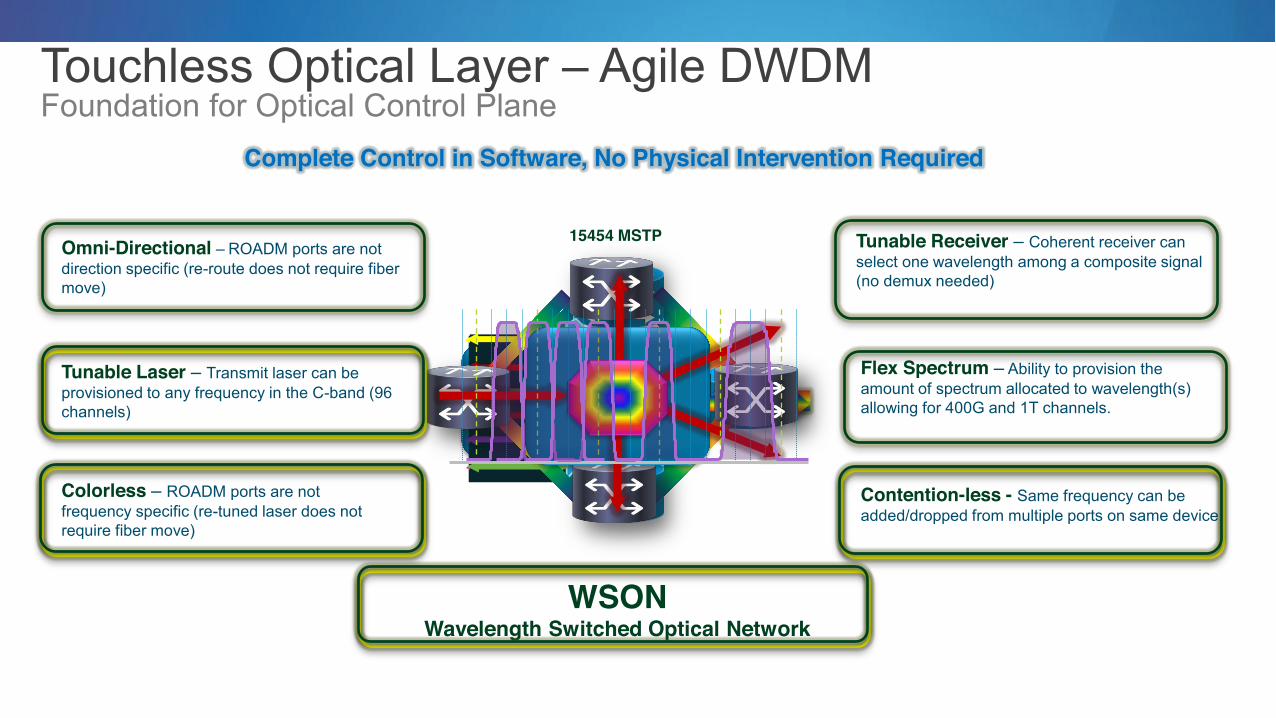
Touchless Optical Layer Agile DWDM Foundation for Optical Control Plane
Embedded Optical Intelligence
Tunable Laser Transmit laser can be provisioned to any frequency in the C-band (96 channels)
Colorless ROADM ports are not frequency specific (re-tuned laser does not require fiber move)
Tunable Receiver Coherent receiver can select one wavelength among a composite signal (no demux needed)
Omni-Directional ROADM ports are not direction specific (re-route does not require fiber move)
Contention-less - Same frequency can be added/dropped from multiple ports on same device.
Flex Spectrum Ability to provision the amount of spectrum allocated to wavelength(s) allowing for 400G and 1T channels.
WSON Wavelength Switched Optical Network
Complete Control in Software, No Physical Intervention Required

nLight Control plane, Intelligent Information Exchange
Packet Layer (client)
DWDM Layer (server)
IGP
QoS Queuing power levels
OSNR CD / PMD
non-liner impairments
physical topology Peering Addressing
GMPLS
nLight Control Plane
G.709
Circuit from A to Z
Proactive Protection Interface Integration
UNI
UNI Extensions
Pre-FEC Threshold Crossing
Network Topology & Feasibility
Matching Path Disjoint Path
SRLG Avoidance Max Latency
Circuit ID and Path Circuit ID and Path SRLG database Path Latencies
Client Requests Server Information

© 2012 Cisco and/or its affiliates. All rights reserved. Cisco Connect 9 Cisco Confidential © 2011 Cisco and/or its affiliates. All rights reserved. 9
Pre-FEC Proactive Protection Reactive Protection Proactive Protection
working route
protect route
fail over
FEC Limit
Pre
-FE
C B
it E
rrors
R
oute
r Bit
Erro
rs
protect route
working route
FEC Limit
Protection Trigger
Pre
-FE
C B
it E
rrors
R
oute
r Bit
Erro
rs
ROADM ROADM
Near Hitless Switch
LOF FEC
FEC
Time Time
Router Router
IP-over-DWDM
Transponder
© 2012 Cisco and/or its affiliates. All rights reserved. Cisco Connect 10
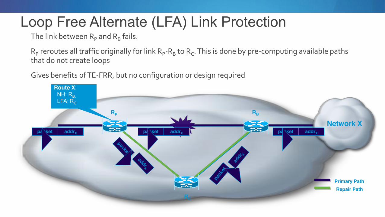
Loop Free Alternate (LFA) Link Protection The link between RP and RB fails.
RP reroutes all traffic originally for link RP-‐RB to RC. This is done by pre-‐computing available paths that do not create loops
Gives benefits of TE-‐FRR, but no configuration or design required
RP RB
RC
Network X packet addrX packet addrX
Primary Path Repair Path
packet addrX
Route X: NH: RB,
LFA: RC

Segment routing Forwarding state (segment) is established by IGP
Agnostic to forwarding dataplane: IPv6 or MPLS RSVP-TE is not required
Source Routing source encodes path as an ordered list of segments two segments: node or adjacency
IPv6 SR Routing Extension header includes the list of segments
Tunnelled solution outer header protects the SR extension header security caches the active SID in the outer DA for backward compatibility

© 2012 Cisco and/or its affiliates. All rights reserved. Cisco Connect 12 Foundation for Next-Generation Edge
Increased Service Velocity Quickly deploy new services
Multi-dimensional Scale System and services scale
ASR 9000v
ASR 9000
ASR 9000v
nV Satellite
nV cluster Network
Cloud
Client
Simplify Operations Reduce overall TCO Integrated A to Z Management
ASR 9000 Network Evolution nV Technology Super, Simple
http://www.cisco.com/web/solutions/sp/asr9000.html
© 2012 Cisco and/or its affiliates. All rights reserved. Cisco Connect 14
L2
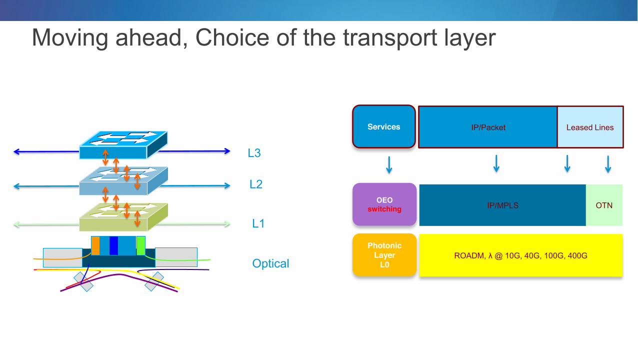
Moving ahead, Choice of the transport layer
L3
L1
Optical
Services
OEO switching
Photonic Layer
L0
IP/Packet Leased Lines
IP/MPLS OTN
ROADM, @ 10G, 40G, 100G, 400G

Cisco Innovation: Key Investments in multi-layer technologiesHere
New Design Ultra-high density, single chip Multiple applications transport-services Power efficient Space Efficient
Custom Silicon NG Software
IOS-XR Evolved Integrated Virtualization Fully modular Zero Packet Loss Zero Topology Loss
IP + DWDM Core Optics & Lightwire Leading 40-100G (400-1T) Low Cost Interconnect Optimized Density / Power
Distance with no regeneration
Optics
Control Plane
Data Plane
Management Plane
Control Plane
Data Plane
Management Plane
Control Plane
Data Plane
Management Plane
BG
B
RIP
ISIS
O
SP
F
Rou
ting
PIM
IGM
P
RIB
L2 D
river
s
AC
L
FIB
QoS
LP
TS
Hos
t Ser
vice
PFI
Inte
rface
CLI
SN
MP
XML
Net
flow
A
larm
P
er.fM
gmt
SS
H S
SH
SS
H
Checkpoint DB Multicast IPC System DB
Distributed Infrastructure
Memory Mgmt IPC Mech Synch. Services Scheduler
Virtualization Multi Layer Control Plane Flexible Routing Virtualization
SDN

© 2013 Cisco and/or its affiliates. All rights reserved. Cisco Connect 16
The SDN Evolution (not Revolution)

Evolution and not Revolution SDN Network Evolution
POLICY ANALYTICS Orchestration
Harvest Network
Intelligence
Program for
Optimized Experience
Network

Programmability at multiple layers of the network Flexibility in deriving abstractions
z Forwarding Plane
Control Plane
Network Services
Management and Orchestration
Transport
Network Elements and Abstraction
Analysis and Monitoring, Performance and Security
OpenFlow/ SDN
Cisco Approach
Application Developer Environment
Harvest Network Intelligence
Program for Optimized
Experience

The Cisco SDN Evolution Overview
Data Plane
Control Plane
Data Plane
Provisioning Controller
Today
Vendor-specific APIs
OF SDN Model Today
Resilient Scalable
Simplified Logical Centralization
Centralised
Distributed
Openflow Protocol
Cisco Evolution Path
Evolved Network Architecture
Orchestration Provisioning
Control
Data Plane
Control Plane
Optimized Best of both worlds
Standard APIs
Abstraction & Programmability

The Collaborative Control Plane Centralized Control Example - Network Optimization
Centralized - PCE TE Path placement
Global topology view
Global TE requirements
Predictable tunnel placement
Network wide optimized tunnel placement
Distributed Head End TE Path Calculation
Global topology view
Local TE requirements
Unpredictable TE tunnel placement
Overall n/w sub-optimal tunnel placement
PCE/ N/W SDN CONTROLLER
Clear benefits for Centralized Control Plane

The Collaborative Control Plane Distributed Control Example IGP Network Convergence
Fully Centralized Control
Major failure multiple devices will be doing this at the same time Impulse load on controller and paths to controller, difficulty correlating of events, failure in paths to controllers
Distributed Network Convergence
RIB
FIB FIB FIB
CPU
CPU CPU CPU
IGP server
Clear benefits for Distributed Control Plane

Evolving How We Interact With Network OS
CLI
AAA
SNMP HTML
XML
Syslog
App
C Java
Python
Span
Netflow
CDP
Routing Protocols
Routing
Data Plane
Policy
Interface
Monitoring
Discovery
IOSd
Any
thin
g yo
u ca
n th
ink
of
Manageability Extensibility
App EEM (TCL)
Events
Actions

onePK for Rapid Application Development Developer Environment
Ubiquitous support
Deploy: On a Service Blade On an External Server Or Directly on the Device
Data Path Policy Element Route Utility
Discovery LISP Developer Rich Service Sets
Java Python C REST
IOS NX-OS IOS-XR
OnePK Infrastructure

Providing a comprehensive environment Flexibility to Choose Protocols, APIs and Developer Environments
ABI
LITY
TO
SPA
N LA
YERS
Packet classifiers Marking Copy/Punt Inject Statistics
Quantum API Interface descriptions L2 network provisioning
RICHNESS OF FEATURES
Element Element Capabilities Configuration Management Interface/Ports Events Location Information
Utilities Syslog Events and Queries AAA Interface Netflow Events DHCP Events
Discovery Network Element Discovery Service Discovery Topology Discovery
Developer Debug Capabilities Tracing Interfaces Management Extensions
Policy Interface Policy Interface Feature Policy Forwarding Policy Flow Action Policy
Routing Protocol Change Events RIB Table Queries
Developer portal
ISVs

© 2013 Cisco and/or its affiliates. All rights reserved. Cisco Connect 25
SDN Modeling

SDN Modeling IP NGN Models
Virtualization associated SDN/NfV
OF-Agent OF-Agent onePK
App App App
Example: Open Flow Controller & Agent
Flow Based SDN
Example: Path Computation
PCC PCC PCC
PCEP
Infrastructure Controller based SDN
Applicability to market segment
Campus IP NGN Data Centre
Applicability to market segment Applicability to market segment
Control Program/ Manager A
Control Program/ Manager B
Example: Network Virtualization

Infrastructure Controller based SDN Use-Case: Multi-Layer PCE with Cisco nLight
DWDM
IP/MPLS
Services
Link
Tunnel
ML-PCE DWDM Topology
(BGP-LS)
Setup Tunnels (PCEP)
L3 Link Topology (BGP-LS)
Service XCON
Setup Service Instances (OF++, IRS)
Discovery, Status nLight

Flow based SDN Use-Case: The Gi-LAN Virtual Services Implementation
Traditional Practice Cloud Practice
Grow Capacity Craft to add a service specific blade to chassis that has finite number of slots
Launch a VM and install the service on it no manual operations
Reconfigure Send craft to re-configure cabling Use data center management and SDN to reconfigure
New Applications (MVNO, M2M
Complex partitioning (MOCN, BSS, GWs Partition using virtualization and SDN
Capacity Limited by slots in NE chassis Unlimited
Fault Recovery HA architectures with high resiliency built-in VMs can be used for quick recovery
Operations Systems FCAPS model Cloud Platform (NM, Orchestration,..)
Distribution of Functions Complex: results in high operational expense Simple via distributed computers & cloud operations
Data Center
Flow based service with Cloud Orchestration
Access GGSN/PGW
FW NAT DPI HTTPProxy
FW
FW VO
VO
A-‐SBC
12ABC3DEF
4GHI5JKL6MNO
7PQRS
8TUV9WXYZ
*0#
Signal Strength
Access GGSN/PGW
FW NAT DPI HTTPProxy
FW
FW VO
VO
A-‐SBC
12ABC3DEF
4GHI5JKL6MNO
7PQRS
8TUV9WXYZ
*0#
Signal Strength
ASR 9000

© 2013 Cisco and/or its affiliates. All rights reserved. Cisco Connect 31
Virtualization associated SDN (NfV)

Telco Cloud Network function Virtualization
NfV Initiative Initiative announced at , Darmstadt, Oct 2012 Industry Specification Group (ISG) group within ETSI Initiative should be a 2 year effort Not defining standards -deliver white papers and liaising with standards bodies First ETSI meeting was held in January
our effort is aimed at appliances
Use of cloud technology to support network functions Management, Control and Data plane components
Not technically related to SDN But may utilize SDN technology APIs, Controllers
Typically uses virtual overlay technology
Introductory White Paper
Open Innovation
Software Defined
Networks
Network Functions
Virtualisation
NfV = Transition of network infrastructure services to run on virtualised compute platforms typically x86

Network Function Virtualization: Use-Case: Virtualization of Network Services, Applications, Functions onto UCS (Demo Available)
Application/Service runs in virtual environment independent of platform (eg, VMs) Plug & Play deployment of services Subscriber-aware service orchestration to define service paths and dynamic service routing
Automate new service introduction and expand/contract resources on the fly Distributed architecture makes no assumptions about scope (free to scale up/down as needed) Expose Network APIs to expose the network as a service end-to-end
ENTERPRISE SERVICES
vRR (Route Reflector) POWER COMPANY M2M
CONSUMER SERVICES (Video Opt, Threat Mngt,
Parental Control) ENTERPRISE SERVICES
ALT SERVICE PROVIDER
Network Infrastructure (IP forwarding plane)
IMS

Virtual Network Services Taxonomy Centralised vs. Distributed > where a service executes within the network?
Centralized services can run in centralised data centres Distributed services need to be distributed further out in the network
Control/Management plane vs. Data/User plane services Control Plane Services deal with signalling and management Examples include DNS, OSS, DHCP, Route Reflector
Data Plane Services forwarding/manipulation of user packets Examples include DPI, NAT, CGN, BRAS, GiLAN services
Redirected traffic vs. routed traffic service > how the traffic gets to the service? Redirected a network device identifies a flow(s) and redirects it from its normal path Routed the traffic will naturally routed through the service
Virtual overlay + service chaining How the traffic gets to and is directed through the service
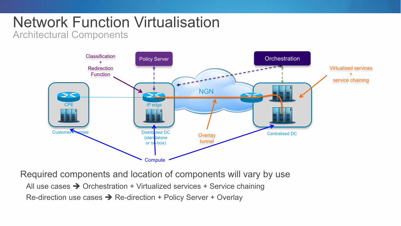
Network Function Virtualisation Architectural Components
Required components and location of components will vary by use All use cases Orchestration + Virtualized services + Service chaining Re-direction use cases Re-direction + Policy Server + Overlay
Centralised DC
Virtualised services +
service chaining
Orchestration
Distributed DC (standalone or on-box)
Policy Server Classification +
Redirection Function
IP edge
Customer Premise
CPE
Overlay tunnel
NGN
Compute

Network Function Virtualization: Use-Case: Virtual CPE (vCPE) e
Centralized Data Centre
Orchestration Policy Server
CPE services
IP Edge
1) Server at customer Premise
Multiple v-CPE models 1. CPE router in premises replaced by a server running virtualized router and services code 2. Very basic CPE router with services functions running in SP Datacentres (similar to a service chaining model) 3. L2 CPE with L3 function held on PE or virtualized compute 4. Cloud connector (UCS on a blade incorporated in a router) Not shown
2) Basic CPE with SP cloud services
3) L2 CPE with L3 services in PE

© 2013 Cisco and/or its affiliates. All rights reserved. Cisco Connect 38
Summary

Summary A new era has begun in NGN network architectures
Advances in technology
TCO pressure along with traffic growth and service velocity needs
Network simplification is comprised of a number of building blocks Network layer collapsing
IP+optical integration (Cisco nLight)
Packet protocol optimizations/simplifications
SDN capabilites
Infrastructure controller, ONE, OF, Openstack
Network Function Virtualization
Real-time OSS

© 2013 Cisco and/or its affiliates. All rights reserved. Cisco Connect 40
Thank you.