the process for manufacturing of ball bearing and · pdf file235 | p a g e the process for...
TRANSCRIPT

235 | P a g e
THE PROCESS FOR MANUFACTURING OF BALL BEARING
AND EFFECT OF MATERIAL IN BEARING LIFE
Amit Tiwari 1, Himanshu Vasnani
2 , Mahendra Labana
3
1, 2 Assistant Professor , Suresh Gyan Vihar University Jaipur, rajasthan India.
3 Enginner, Safety Department. MBECL ZAWAR MINES Udaipur( Rajasthan)
ABSTRACT
In this paper design of angular contact ball bearing is done which is used in Propeller shaft of an air craft.
This type of ball bearing can support radial load and axial load in both directions due to the points of contact
available. The inner ring of a point angular contact ball bearing is split so because of larger ball quantity,
higher carrying capacity is possible.Whether for industrial, transportation or complex systems, ball bearing
are considered as major factor in kinematics rotating systems. Apart from their strategic role in the drive
assemblies, these mechanical components can require an increased rate of reliability. Bearings turbines and
rotating machines are primordial in most mechanical components which contribute directly to the
performance of automotive and aerospace engines through reliability. Due to their role as liaison between
fixed and moving parts, any failure could have catastrophic consequences such as loss of engine use. This
research is aimed to develop the analytical fundamentals details of new model which is dedicated to the
dynamic behaviour of rotating ball bearings.
Key Words: Bearing Materials , Manufacturing Process and Testing of bearing.
I. INTRODUCTION
A bearing is a machine element that constrains relative motion to only the desired motion, and reduces friction
between moving parts. The design of the bearing may, for example, provide for free linear movement of the
moving part or for free rotation around a fixed axis; or, it may prevent a motion by controlling
the vectors of normal forces that bear on the moving parts. Many bearings also facilitate the desired motion as
much as possible, such as by minimizing friction. Bearings are classified broadly according to the type of
operation, the motions allowed, or to the directions of the loads (forces) applied to the parts. In simple terms,
roller bearings locate rotating components such as shafts or axles within mechanical systems, and transfer axial
and radial loads from the source of the load to the structure supporting it. To minimize friction, heat, power loss
and wear, rolling elements such known as rollers or balls with a circular cross-section are located between the
races or journals of the bearing assembly. A wide variety of bearing designs exists to allow the demands of the
application to be correctly met for maximum efficiency, reliability, durability and performance. The term
"bearing" is derived from the verb to bear a bearing being a machine element that allows one part to bear (i.e., to
support) another. The simplest bearings are bearing surfaces, cut or formed into a part, with varying degrees of
control over the form, size, roughness and location of the surface. Other bearings are separate devices installed
236 | P a g e
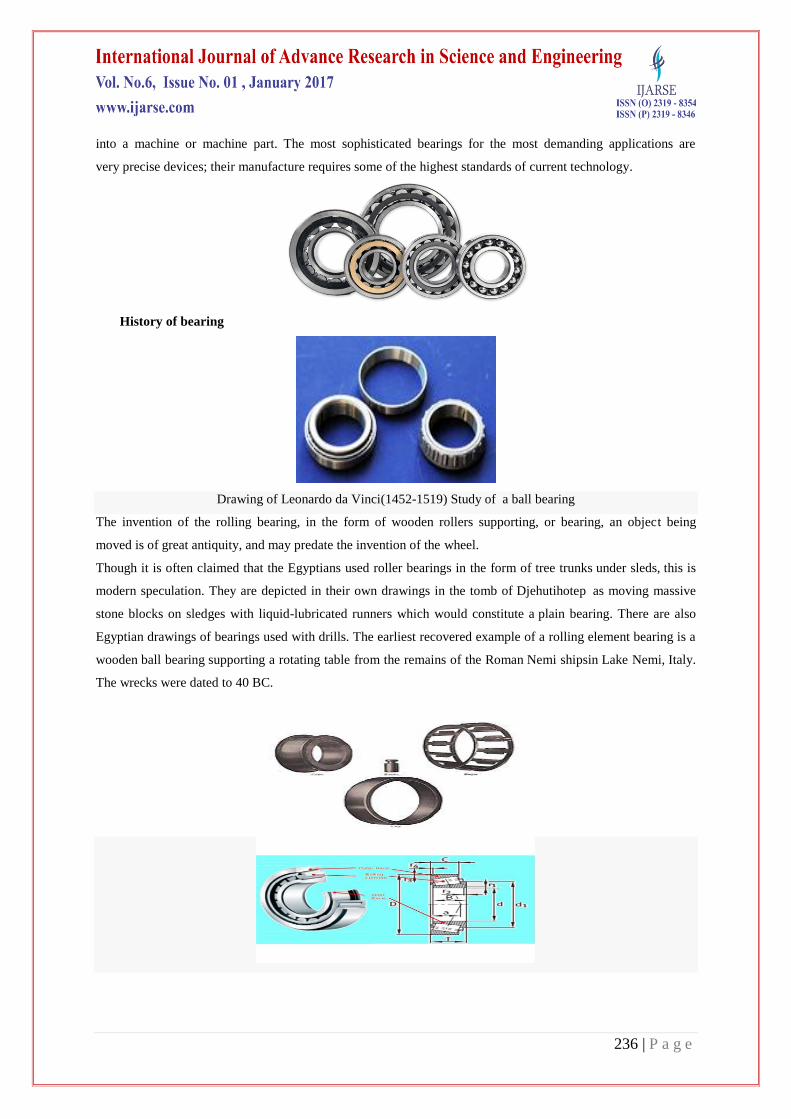
into a machine or machine part. The most sophisticated bearings for the most demanding applications are
very precise devices; their manufacture requires some of the highest standards of current technology.
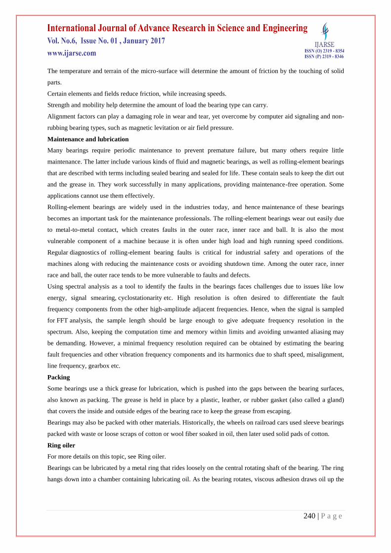
History of bearing
Drawing of Leonardo da Vinci(1452-1519) Study of a ball bearing
The invention of the rolling bearing, in the form of wooden rollers supporting, or bearing, an object being
moved is of great antiquity, and may predate the invention of the wheel.
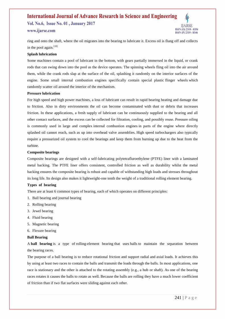
Though it is often claimed that the Egyptians used roller bearings in the form of tree trunks under sleds, this is
modern speculation. They are depicted in their own drawings in the tomb of Djehutihotep as moving massive
stone blocks on sledges with liquid-lubricated runners which would constitute a plain bearing. There are also
Egyptian drawings of bearings used with drills. The earliest recovered example of a rolling element bearing is a
wooden ball bearing supporting a rotating table from the remains of the Roman Nemi shipsin Lake Nemi, Italy.
The wrecks were dated to 40 BC.

237 | P a g e
Designed in 1968 and later patented in 1972, Bishop-Wisecarver's co-founder Bud Wisecarver created vee
groove bearing guide wheels, a type of linear motion bearing consisting of both an external and internal 90-
degree vee angle.
In the early 1980s, Pacific Bearing's founder, Robert Schroeder, invented the first bi-material plain bearing
which was size interchangeable with linear ball bearings. This bearing had a metal shell (aluminum, steel or
stainless steel) and a layer of Teflon-based material connected by a thin adhesive layer.
Today ball and roller bearings are used in many applications which include a rotating component. Examples
include ultra high speed bearings in dental drills, aerospace bearings in the Mars Rover, gearbox and wheel
bearings on automobiles, flexure bearings in optical alignment systems, bicycle wheel hubs, and air
bearings used in Coordinate-measuring machines.
BEARING MATERIAL
Bearings Made of Chrome Steel - SAE 52100
The most common material used to produce the load carrying components in precision ball bearings, roller
bearings, and tapered roller bearings is 52100 chrome steel. These components are the bearings inner and outer
rings, balls and rollers. The chemical composition of this steel has high carbon and about 1.5% chromium
content. Using controlled processing and heat-treating methods the finished bearing components have high
strength to resist cracking and a hard surface to resist subsurface rolling contact fatigue. The typical surface
hardness for bearing components made from this material ranges from 60- 64 on the Rockwell hardness C scale
(Rc).
Extra clean 52100 chrome steel
The raw steel used to produce high precision miniature bearings is processed with additional melting steps. The
result is a type of steel with very uniform fine grain material structure, the bearing contact surfaces can be super
finished very smooth so the bearing is very quiet.
The most common heat treating method for chrome steel is to thru harden the steel in a controlled atmosphere
furnace. Bearings manufactured from chrome steel can operate at continuous temperatures up to 120°C.
Where higher temperatures are encountered, it is possible to Heat Stabilize the bearing components. By varying
the heat treating process, bearings can be produced so they are capable of operating at temperatures of 220°C,
and higher. For these applications, the components must be subjected to a tempering treatment at a higher
temperature corresponding to the service temperature. This elevated tempering treatment has a detrimental
effect on the hardness of the material and the load carrying capacity of the bearing is reduced.
SAE 52100 is an excellent general purpose bearing steel. Due to its excellent hardness and wear resistance, it
exhibits good fatigue life in rolling element bearings. However, the corrosion resistance of chrome steel is poor
because of the low chromium content. The surfaces of the bearings must be protected with a coating of rust
inhibitor or oil to stop oxidation.
As can be seen in the following table, the standard chemical composition of chromium steel will vary depending
on the country where it is produced.

238 | P a g e
Bearings Made of Stainless Steels
Stainless steel materials are used to make bearing components because it is more resistant to surface corrosion
due to the higher content of chromium (~18%) with the addition of nickel. The chromium reacts with oxygen to
form a layer of chromium oxide on the surface, creating a passive film.
Martensitic Stainless Steel - AISI 440C
The carbon content in 400 series stainless steels is high enough so it can be hardened using standard heat-
treating methods up to Rc58. Due to the lower hardness, the load carrying capacity is 20% lower in bearings
made from this material, than they are with 52100 chrome steel bearings. The level of carbon content means the
components are magnetic. The corrosion resistance is “good”, when 440C material is exposed to fresh water and
mild chemicals. This material is primarily used by US bearing manufacturers.
Miniature bearings made from conventional 440C stainless steel will be slightly noisy because the large carbides
that normally concentrate at the grain boundaries are exposed in the raceway finishing process. Larger bore
bearings are not as affected by this condition. Bearings made from 400 series stainless steel can operate at
higher temperatures than chrome steel, up to 250°C continuous. Bearings made from this material are generally
more expensive than chrome steel bearings.
Common case of bearing
Motion
Common motions permitted by bearings are:
axial rotation e.g. shaft rotation
linear motion e.g. drawer
spherical rotation e.g. ball and socket joint
hinge motion e.g. door, elbow, knee
Friction
Reducing friction in bearings is often important for efficiency, to reduce wear and to facilitate extended use at
high speeds and to avoid overheating and premature failure of the bearing. Essentially, a bearing can reduce
friction by virtue of its shape, by its material, or by introducing and containing a fluid between surfaces or by
separating the surfaces with an electromagnetic field.
By shape, gains advantage usually by using spheres or rollers, or by forming flexure bearings.
By material, exploits the nature of the bearing material used. (An example would be using plastics that have
low surface friction.)
By fluid, exploits the low viscosity of a layer of fluid, such as a lubricant or as a pressurized medium to
keep the two solid parts from touching, or by reducing the normal force between them.
By fields, exploits electromagnetic fields, such as magnetic fields, to keep solid parts from touching.
""Air pressure"" exploits air pressure to keep solid parts from touching.
Combinations of these can even be employed within the same bearing. An example of this is where the cage is
made of plastic, and it separates the rollers/balls, which reduce friction by their shape and finish.
Loads
Bearings vary greatly over the size and directions of forces that they can support.

239 | P a g e
Forces can be predominately radial, axial (thrust bearings) or bending moments perpendicular to the main axis.
Speeds
Different bearing types have different operating speed limits. Speed is typically specified as maximum relative
surface speeds, often specified ft/s or m/s. Rotational bearings typically describe performance in terms of the
product DN where D is the mean diameter (often in mm) of the bearing and N is the rotation rate in revolutions
per minute.
Generally there is considerable speed range overlap between bearing types. Plain bearings typically handle only
lower speeds, rolling element bearings are faster, followed by fluid bearings and finally magnetic bearings
which are limited ultimately by centripetal force overcoming material strength.
Stiffness
A second source of motion is elasticity in the bearing itself. For example, the balls in a ball bearing are like stiff
rubber, and under load deform from round to a slightly flattened shape. The race is also elastic and develops a
slight dent where the ball presses on it.
The stiffness of a bearing is how the distance between the parts which are separated by the bearing varies with
applied load. With rolling element bearings this is due to the strain of the ball and race. With fluid bearings it is
due to how the pressure of the fluid varies with the gap (when correctly loaded, fluid bearings are typically
stiffer than rolling element bearings).
Service life
Fluid and magnetic bearings
Fluid and magnetic bearings can have practically indefinite service lives. In practice, there are fluid bearings
supporting high loads in hydroelectric plants that have been in nearly continuous service since about 1900 and
which show no signs of wear.
Rolling element bearing
Rolling element bearing life is determined by load, temperature, maintenance, lubrication, material defects,
contamination, handling, installation and other factors. These factors can all have a significant effect on bearing
life. For example, the service life of bearings in one application was extended dramatically by changing how the
bearings were stored before installation and use, as vibrations during storage caused lubricant failure even when
the only load on the bearing was its own weight; the resulting damage is often false brinelling. Bearing life is
statistical: several samples of a given bearing will often exhibit a bell curve of service life, with a few samples
showing significantly better or worse life. Bearing life varies because microscopic structure and contamination
vary greatly even where macroscopically they seem identical.
External factors
The service life of the bearing is affected by many parameters that are not controlled by the bearing
manufacturers. For example, bearing mounting, temperature, exposure to external environment, lubricant
cleanliness and electrical currents through bearings etc. The disruption from PWM inverter which are generating
high frequency motorbearing currents can be suppressed by inductive absorbers like CoolBLUE cores, which
need to be put over the three phases giving a high frequency impedance against the common mode or
motorbearing currents.
240 | P a g e
The temperature and terrain of the micro-surface will determine the amount of friction by the touching of solid
parts.
Certain elements and fields reduce friction, while increasing speeds.
Strength and mobility help determine the amount of load the bearing type can carry.
Alignment factors can play a damaging role in wear and tear, yet overcome by computer aid signaling and non-
rubbing bearing types, such as magnetic levitation or air field pressure.
Maintenance and lubrication
Many bearings require periodic maintenance to prevent premature failure, but many others require little
maintenance. The latter include various kinds of fluid and magnetic bearings, as well as rolling-element bearings
that are described with terms including sealed bearing and sealed for life. These contain seals to keep the dirt out
and the grease in. They work successfully in many applications, providing maintenance-free operation. Some
applications cannot use them effectively.
Rolling-element bearings are widely used in the industries today, and hence maintenance of these bearings
becomes an important task for the maintenance professionals. The rolling-element bearings wear out easily due
to metal-to-metal contact, which creates faults in the outer race, inner race and ball. It is also the most
vulnerable component of a machine because it is often under high load and high running speed conditions.
Regular diagnostics of rolling-element bearing faults is critical for industrial safety and operations of the
machines along with reducing the maintenance costs or avoiding shutdown time. Among the outer race, inner
race and ball, the outer race tends to be more vulnerable to faults and defects.
Using spectral analysis as a tool to identify the faults in the bearings faces challenges due to issues like low
energy, signal smearing, cyclostationarity etc. High resolution is often desired to differentiate the fault
frequency components from the other high-amplitude adjacent frequencies. Hence, when the signal is sampled
for FFT analysis, the sample length should be large enough to give adequate frequency resolution in the
spectrum. Also, keeping the computation time and memory within limits and avoiding unwanted aliasing may
be demanding. However, a minimal frequency resolution required can be obtained by estimating the bearing
fault frequencies and other vibration frequency components and its harmonics due to shaft speed, misalignment,
line frequency, gearbox etc.
Packing
Some bearings use a thick grease for lubrication, which is pushed into the gaps between the bearing surfaces,
also known as packing. The grease is held in place by a plastic, leather, or rubber gasket (also called a gland)
that covers the inside and outside edges of the bearing race to keep the grease from escaping.
Bearings may also be packed with other materials. Historically, the wheels on railroad cars used sleeve bearings
packed with waste or loose scraps of cotton or wool fiber soaked in oil, then later used solid pads of cotton.
Ring oiler
For more details on this topic, see Ring oiler.
Bearings can be lubricated by a metal ring that rides loosely on the central rotating shaft of the bearing. The ring
hangs down into a chamber containing lubricating oil. As the bearing rotates, viscous adhesion draws oil up the
241 | P a g e
ring and onto the shaft, where the oil migrates into the bearing to lubricate it. Excess oil is flung off and collects
in the pool again.[18]
Splash lubrication
Some machines contain a pool of lubricant in the bottom, with gears partially immersed in the liquid, or crank
rods that can swing down into the pool as the device operates. The spinning wheels fling oil into the air around
them, while the crank rods slap at the surface of the oil, splashing it randomly on the interior surfaces of the
engine. Some small internal combustion engines specifically contain special plastic flinger wheels which
randomly scatter oil around the interior of the mechanism.
Pressure lubrication
For high speed and high power machines, a loss of lubricant can result in rapid bearing heating and damage due
to friction. Also in dirty environments the oil can become contaminated with dust or debris that increases
friction. In these applications, a fresh supply of lubricant can be continuously supplied to the bearing and all
other contact surfaces, and the excess can be collected for filtration, cooling, and possibly reuse. Pressure oiling
is commonly used in large and complex internal combustion engines in parts of the engine where directly
splashed oil cannot reach, such as up into overhead valve assemblies. High speed turbochargers also typically
require a pressurized oil system to cool the bearings and keep them from burning up due to the heat from the
turbine.
Composite bearings
Composite bearings are designed with a self-lubricating polytetrafluroethylene (PTFE) liner with a laminated
metal backing. The PTFE liner offers consistent, controlled friction as well as durability whilst the metal
backing ensures the composite bearing is robust and capable of withstanding high loads and stresses throughout
its long life. Its design also makes it lightweight-one tenth the weight of a traditional rolling element bearing.
Types of bearing
There are at least 6 common types of bearing, each of which operates on different principles:
1. Ball bearing and journal bearing
2. Rolling bearing
3. Jewel bearing
4. Fluid bearing
5. Magnetic bearing
6. Flexure bearing
Ball Bearing
A ball bearing is a type of rolling-element bearing that uses balls to maintain the separation between
the bearing races.
The purpose of a ball bearing is to reduce rotational friction and support radial and axial loads. It achieves this
by using at least two races to contain the balls and transmit the loads through the balls. In most applications, one
race is stationary and the other is attached to the rotating assembly (e.g., a hub or shaft). As one of the bearing
races rotates it causes the balls to rotate as well. Because the balls are rolling they have a much lower coefficient
of friction than if two flat surfaces were sliding against each other.
242 | P a g e
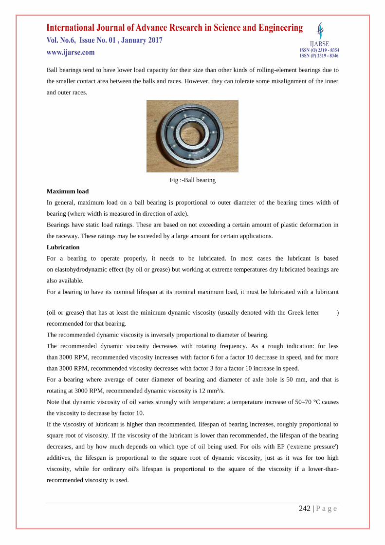
Ball bearings tend to have lower load capacity for their size than other kinds of rolling-element bearings due to
the smaller contact area between the balls and races. However, they can tolerate some misalignment of the inner
and outer races.
Fig :-Ball bearing
Maximum load
In general, maximum load on a ball bearing is proportional to outer diameter of the bearing times width of
bearing (where width is measured in direction of axle).
Bearings have static load ratings. These are based on not exceeding a certain amount of plastic deformation in
the raceway. These ratings may be exceeded by a large amount for certain applications.
Lubrication
For a bearing to operate properly, it needs to be lubricated. In most cases the lubricant is based
on elastohydrodynamic effect (by oil or grease) but working at extreme temperatures dry lubricated bearings are
also available.
For a bearing to have its nominal lifespan at its nominal maximum load, it must be lubricated with a lubricant
(oil or grease) that has at least the minimum dynamic viscosity (usually denoted with the Greek letter )
recommended for that bearing.
The recommended dynamic viscosity is inversely proportional to diameter of bearing.
The recommended dynamic viscosity decreases with rotating frequency. As a rough indication: for less
than 3000 RPM, recommended viscosity increases with factor 6 for a factor 10 decrease in speed, and for more
than 3000 RPM, recommended viscosity decreases with factor 3 for a factor 10 increase in speed.
For a bearing where average of outer diameter of bearing and diameter of axle hole is 50 mm, and that is
rotating at 3000 RPM, recommended dynamic viscosity is 12 mm²/s.
Note that dynamic viscosity of oil varies strongly with temperature: a temperature increase of 50–70 °C causes
the viscosity to decrease by factor 10.
If the viscosity of lubricant is higher than recommended, lifespan of bearing increases, roughly proportional to
square root of viscosity. If the viscosity of the lubricant is lower than recommended, the lifespan of the bearing
decreases, and by how much depends on which type of oil being used. For oils with EP ('extreme pressure')
additives, the lifespan is proportional to the square root of dynamic viscosity, just as it was for too high
viscosity, while for ordinary oil's lifespan is proportional to the square of the viscosity if a lower-than-
recommended viscosity is used.
243 | P a g e
Lubrication can be done with a grease, which has advantages that grease is normally held within the bearing
releasing the lubricant oil as it is compressed by the balls. It provides a protective barrier for the bearing metal
from the environment, but has disadvantages that this grease must be replaced periodically, and maximum load
of bearing decreases (because if bearing gets too warm, grease melts and runs out of bearing). Time between
grease replacements decreases very strongly with diameter of bearing: for a 40 mmbearing, grease should be
replaced every 5000 working hours, while for a 100 mm bearing it should be replaced every 500 working hours.
Lubrication can also be done with an oil, which has advantage of higher maximum load, but needs some way to
keep oil in bearing, as it normally tends to run out of it. For oil lubrication it is recommended that for
applications where oil does not become warmer than 50 °C, oil should be replaced once a year, while for
applications where oil does not become warmer than 100 °C, oil should be replaced 4 times per year. For car
engines, oil becomes 100 °C but the engine has an oil filter to maintain oil quality; therefore, the oil is usually
changed less frequently than the oil in bearings.
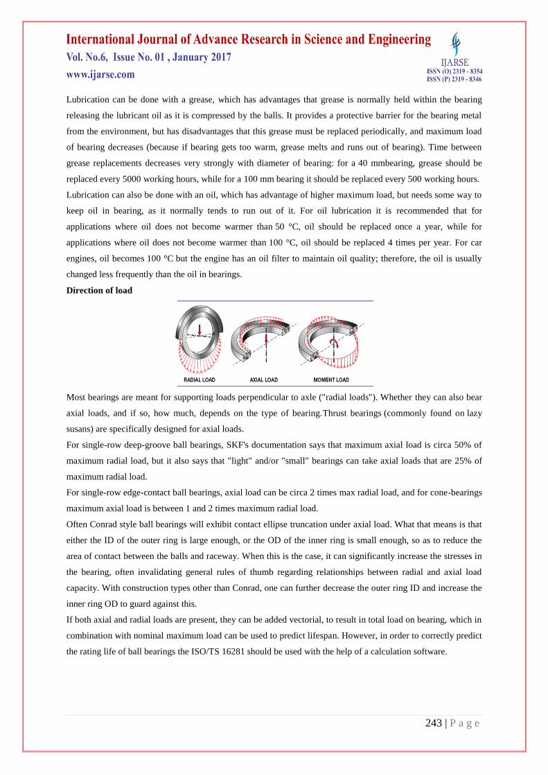
Direction of load
Most bearings are meant for supporting loads perpendicular to axle ("radial loads"). Whether they can also bear
axial loads, and if so, how much, depends on the type of bearing.Thrust bearings (commonly found on lazy
susans) are specifically designed for axial loads.
For single-row deep-groove ball bearings, SKF's documentation says that maximum axial load is circa 50% of
maximum radial load, but it also says that "light" and/or "small" bearings can take axial loads that are 25% of
maximum radial load.
For single-row edge-contact ball bearings, axial load can be circa 2 times max radial load, and for cone-bearings
maximum axial load is between 1 and 2 times maximum radial load.
Often Conrad style ball bearings will exhibit contact ellipse truncation under axial load. What that means is that
either the ID of the outer ring is large enough, or the OD of the inner ring is small enough, so as to reduce the
area of contact between the balls and raceway. When this is the case, it can significantly increase the stresses in
the bearing, often invalidating general rules of thumb regarding relationships between radial and axial load
capacity. With construction types other than Conrad, one can further decrease the outer ring ID and increase the
inner ring OD to guard against this.
If both axial and radial loads are present, they can be added vectorial, to result in total load on bearing, which in
combination with nominal maximum load can be used to predict lifespan. However, in order to correctly predict
the rating life of ball bearings the ISO/TS 16281 should be used with the help of a calculation software.

244 | P a g e
Turning operation
Turning is a machining process in which a cutting tool, typically a non-rotary tool bit, describes
a helix toolpath by moving more or less linearly while the workpiece rotates. The tool's axes of movement
may be literally a straight line, or they may be along some set of curves or angles, but they are essentially
linear (in the non mathematical sense). Usually the term "turning" is reserved for the generation
ofexternal surfaces by this cutting action, whereas this same essential cutting action when applied
to internal surfaces (that is, holes, of one kind or another) is called "boring". Thus the phrase "turning and

245 | P a g e
boring" categorizes the larger family of (essentially similar) processes. The cutting of faces on the
workpiece (that is, surfaces perpendicular to its rotating axis), whether with a turning or boring tool, is
called "facing", and may be lumped into either category as a subset.
Turning can be done manually, in a traditional form of lathe, which frequently requires continuous
supervision by the operator, or by using an automated lathe which does not. Today the most common type
of such automation is computer numerical control, better known as CNC. (CNC is also commonly used
with many other types of machining besides turning.)
When turning, a piece of relatively rigid material (such as wood, metal, plastic, or stone) is rotated and
a cutting tool is traversed along 1, 2, or 3 axes of motion to produce precise diameters and depths. Turning
can be either on the outside of the cylinder or on the inside (also known as boring) to produce tubular
components to various geometries. Although now quite rare, early lathes could even be used to produce
complex geometric figures, even the platonic solids; although since the advent of CNC it has become
unusual to use non-computerized toolpath control for this purpose.
The turning processes are typically carried out on a lathe, considered to be the oldest machine tools, and can
be of four different types such as straight turning, taper turning, profiling or external grooving. Those types
of turning processes can produce various shapes of materials such as straight, conical, curved,
or grooved workpiece. In general, turning uses simple single-point cutting tools. Each group of workpiece
materials has an optimum set of tools angles which have been developed through the years.
Forces
The relative forces in a turning operation are important in the design of machine tools. The machine tool and its
components must be able to withstand these forces without causing significant deflections, vibrations, or chatter
during the operation. There are three principal forces during a turning process:
The cutting or tangential force acts downward on the tool tip allowing deflection of the workpiece upward.
It supplies the energy required for the cutting operation.The specific cutting force required to cut the
material is called specific cutting force.Cutting force is depends on the material.
The axial or feed force acts in the longitudinal direction. It is also called the feed force because it is in the
feed direction of the tool. This force tends to push the tool away from the chuck.
The radial or thrust force acts in the radial direction and tends to push the tool away from the workpiece.
Speeds and feeds
Speeds and feeds for turning are chosen based on cutter material, workpiece material, setup rigidity, machine
tool rigidity and spindle power, coolant choice, and other factors.
Feed
The distance the tool advances into the material in one revolution is called "feed". It is specified as mm per
revolution (mm/rev).
Centreless grinding

246 | P a g e
Fig :- centerless grinding process
Centerless grinding is a machining process that uses abrasive cutting to remove material from a
workpiece. Centerless grinding differs from centered grinding operations in that no spindle or fixture is
used to locate and secure the workpiece; the workpiece is secured between two rotary grinding wheels, and
the speed of their rotation relative to each other determines the rate at which material is removed from the
workpiece.
Centerless grinding is typically used in preference to other grinding processes for operations where many parts
must be processed in a short time.
Process
Fig:-centre less grinding
In centerless grinding, the workpiece is held between two grinding wheels, rotating in the same direction at
different speeds, and a workholding platform. One wheel, known as the grinding wheel (stationary wheel in
the diagram), is on a fixed axis and rotates such that the force applied to the workpiece is directed
downward, against the workholding platform. This wheel usually performs the grinding action by having a
higher tangential speed than the workpiece at the point of contact. The other wheel, known as the regulating
wheel (moving wheel in the diagram), is movable. This wheel is positioned to apply lateral pressure to the
workpiece, and usually has either a very rough or rubber-bonded abrasive to trap the workpiece.
The speed of the two wheels relative to each other provides the grinding action and determines the rate at
which material is removed from the workpiece. During operation the workpiece turns with the regulating
wheel, with the same linear velocity at the point of contact and (ideally) no slipping. The grinding wheel
turns faster, slipping past the surface of the workpiece at the point of contact and removing chips of
material as it passes.

247 | P a g e
Heat treatment
Heat treating furnace at 1,800 °F (980 °C)
Heat treating is a group of industrial and metalworking processes used to alter the physical, and
sometimes chemical, properties of a material.
The most common application is metallurgical. Heat treatments are also used in the manufacture of many
other materials, such as glass.
Heat treatment involves the use of heating or chilling, normally to extreme temperatures, to achieve a
desired result such as hardening or softening of a material.
Heat treatment techniques include annealing, case hardening, precipitation strengthening,tempering,
normalizing and quenching. It is noteworthy that while the term heat treatment applies only to processes
where the heating and cooling are done for the specific purpose of altering properties intentionally, heating
and cooling often occur incidentally during other manufacturing processes such as hot forming or welding.
Hardness testing
Different types of hardness testing as like:
Rockwell hardness testing
Brinell hardness testing
Universal hardness testing
Rockwell
The Rockwell scale is a hardness scale based on indentation hardness of a material. The Rockwell test
determines the hardness by measuring the depth of penetration of an indenter under a large load compared
to the penetration made by a preload.
Tinius Olsen has many types of hardness testers available that can rapidly and accurately determine the
hardness value of a wide variety of materials including metals, plastics, large parts, small precision parts.
Whether you need are bench mounted testers, large scale floor mounted testers or dedicated testers that are
integrated into your production lines, we can help you with your application.

248 | P a g e
Fig :-Rockwell hardness testing of ball bearing
Brinell
The Brinell scale characterizes teh indentation hardness of materials through the scale penetration of an
indenter, loaded on a material test-piece.
Tinius Olsen has many types of hardness testers available that can rapidly and accurately determine the
hardness value of a wide variety of materials including metals, plastics, large parts, small precision parts.
Whether you need are bench mounted testers, large scale floor mounted testers or dedicated testers that are
integrated into your production lines, we can help you with your application.
Fig :-Brinell hardness testing

249 | P a g e
Honing and super finishing
The surface of a honed workpiece.
Honing is an abrasive machining process that produces a precision surface on a metal workpiece by
scrubbing an abrasive stone against it along a controlled path. Honing is primarily used to improve the
geometric form of a surface, but may also improve the surface texture.
Typical applications are the finishing of cylinders for internal combustion engines, air
bearing spindles and gears. There are many types of hones but all consist of one or more abrasive stones
that are held under pressure against the surface they are working on.
In terms of sharpening knives, a honing steel does not actually hone knives, but simply realigns the metal
along the edge.
Other similar processes are lapping and superfinishing.
Process mechanism
Fig :-honing & superfinishing process
Since honing stones look similar to grinding wheels, it is tempting to think of honing as a form of low-
stock removal grinding. Instead, it is better to think of it as a self-truing grinding process.
In grinding, the wheel follows a simple path. For example, in plunge grinding a shaft, the wheel moves in
towards the axis of the part, grinds it, and then moves back out. Since each slice of the wheel repeatedly
contacts the same slice of the workpiece, any inaccuracies in the geometric shape of the grinding wheel
will be transferred onto the part. Therefore, the accuracy of the finished workpiece geometry is limited to

250 | P a g e
the accuracy of the truing dresser. The accuracy becomes even worse as the grind wheel wears, so truing
must occur periodically to reshape it.
The limitation on geometric accuracy is overcome in honing because the honing stone follows a complex
path. In bore honing for example, the stone moves along two paths simultaneously.
The path of the stone is not the only difference between grinding and honing machines, they also differ in
the stiffness of their construction. Honing machines are much more compliant than grinders.
Application of rust preventive
Rustproofing is the prevention or delay of rusting of iron and steel objects, or the
permanent protection against corrosion. Typically the protection is achieved by a process ofsurface
finishing or treatment. Depending on mechanical wear or environmental conditions, the degradation may
not be stopped completely, unless the process is periodically repeated. The term is particularly used in
the automobile industry
Ready for dispatch to assembly
Business
Zurn Engineered Water Solutions® is a recognized leader in commercial, municipal, and industrial markets.
Zurn manufactures the largest breadth of engineered water solutions in the industry, including a wide spectrum
of sustainable plumbing products. Zurn delivers total building solutions for new construction and retrofit
applications that enhance any building’s environment.
CONCLUSION
The paper presents a cross-section study of static behavior of bearings as well as works related to the
determination of the bearing life. Additionally the theoretical basis for defining mathematical models for

251 | P a g e
determining deformation, stiffness, changes in contact angle and the determination of bearing life with angular
contact. Also, some research results of the static behavior of bearings, and verification of mathematical models
of bearings for special applications and single-ball bearing with angular contact, for support the main spindle of
machine tools and two rows the ball bearing with angular contact for support a car wheel are presented. From
the results it can be concluded that the mathematical model satisfactory describes the static behavior of ball
bearings from the point of deformation and stiffness. Based on the results of ball bearings life.
REFERENCES
[1]. Perret H. (1950). Elastischen Spielschwingungen konstant belaster alzlager. Werkstatt und Betrieb,
83(C5):354-358.
[2]. Meldau, E. (1951). Die Bewechung der Achse von Walzlagern bei geringen Drehzahlen. Werkstatt und
Betrieb, 84(C5):308-313.
[3]. D. DOWSON, G. R. Higginson. Elasto-hydrodynamic lubrication. 2nd ed. Oxford: Pergamon Press, 1977,
235 p.
[4]. B. J. HAMROCK, D. DOWSON, Isothermal elastohydrodynamic lubrication of point contacts. Part IV –
Starvation results. ASME journal of lubrication technology series F, 1977, vol. 99, n°2, pp. 15-23.
[5]. W. WANG P. L. WONG, F. HE, G. T. Y. WAN, Experimental study of the smoothing effect of a ceramic
rolling element on a bearing raceway in contaminated lubrication, Springer Tribol. Lett, 28, 2007, pp 89-97
DOI 10.1007/s11249-007-9251-8
[6]. C. JACQ, Limite d’endurance et durée de vie en fatigue de roulement du 32CrMoV13 nitruré en présence
d’indentations. Thèse en Génie des Matériaux de l’Institut National des Sciences Appliquées de Lyon,
2001, N° d’ordre 2001-ISAL-0085.
[7]. W. CHENG, H. S. CHENG, Semi Analytical Modelling of Crack Initiation Dominant Contact Fatigue Life
for Roller Bearings ASME Journal of Tribology, Vol. 119, 1997, pp. 233-239.
[8]. K. TANAKA, T. MURA, a dislocation model for fatigue crack initiation, Journal of Applied Mechanics,
Vol. 48, 1981, pp. 97-103.
[9]. L.M. KEER, and M. D. BRYANT, A Pitting Model of Contact Fatigue, ASME Journal of Lubrication
Technology, Vol. 105, No. 2, 1983, pp. 198- 205.
[10]. J. K. LEE, and L. M. KEER, “Study of a Three-Dimensional Crack Terminating at an Interface” ASME
Journal of Applied Mechanics, Vol. 108, 1986, pp. 316-331.
[11] Jing Liu, Yimin Shao, Teik C. Lim, “Vibration analysis of ball bearings with a localized defect applying
piecewise response function”, Mechanism and Machine Theory 56 (2012) 156–169.
[12] Yuan Kanga, Chih-Ching Huang, Chorng-Shyan Lin, Ping-Chen Shen, Yeon-Pun Changa, “Stiffness
determination of angular-contact ballbearings by using neural network”, Tribology International 39 (2006)
461–469.
[13] Mohsen Mosleh, Keron Bradshaw, “Role of component configuration in evaluation of accelerated rolling
contact fatigue of ball bearings”, Wear271 (2011) 2681– 2686.

252 | P a g e
[14] Shoji Noguchi, Tohru Kanada b, “3- and Contact Point Spindle Bearings-a new Approach for High Speed
Spindle Systems”, Laboratory of Machine Tools and Production Engineering. Aachen. Germany
[15] J. Jedrzejewski, W. Kwasny, “Modelling of angular contact ball bearings and axial displacements for high-
speed spindles”, CIRP Annals - Manufacturing Technology 59 (2010) 377–382.
[16] TEDRIC, A. H., MICHAEL, N. K.: Rolling bearing analysis: Essential Concepts of Bearing Technology,
Fifth edition, Taylor & Francis Group, ISBN: 0- 8493-7183-X, 2007
[17] WANG, L., SNIDLE, R. W.; GU, L.: Rolling contact silicon nitride bearing technology: a review of
recent research, Wear Vol.246, ISSN: , 2000, Pages 159– 173.
[18] WECK, M., SPACHHOK, G.: 3 - and 4 &Contact Point Spindle Bearings -a new Approach for High
Speed Spindle Systems, CIRP Annals-Manufacturing Technology Vol 52, Issue 1, ISSN: 0007-8506,
2003, Pages 311-316.