the present work, produced by the ecosign consortium, is
TRANSCRIPT

Ecoinnovation Skills for European Designers, Project number: 562573-EPP-1-2015-1-SI-EPPKA2-SSA.Disclaimer: The European Commission support for the production of this publication does not constitute endorsement of the contents which reflects the views only of the authors, and the Commission cannot be held responsible forany use which may be made of the information contained therein
Ecodesign of Electronic Devices
UNIT 8: Microcontroller systems part 1
The present work, produced by the ECOSIGN Consortium, is licensed under a Creative Commons Attribution-NonCommercial-NoDerivatives 4.0 International License.

2| UNIT 8: Microcontroller systems part 1
Today's microcontroller production reaches billions of pieces yearly with numerous different manufacturers.Today's electronic systems are hard to imagine without a microcontroller, and their use is constantly rising. Hereare a few groups of devices that use microcontroller systems:
Household appliances (microwaves, washing machines, coffee machines, etc..).
Telecommunication (telephones, smartphones, modems, routers, etc..).
Consumer electronics (television sets, music and video players, gaming consoles, etc..)
Industry (management and control of devices and production processes).
Automotive industry (engine control, safety driving system, etc.. ).
Space technology.
Introduction to microcontroller systems
3| UNIT 8: Microcontroller systems part 1
Microcontroller systems have flourished and are a great substitution for analog systems and circuits. With the inclusion of microcontroller systems into device design we can greatly decrease device sizing, increase efficiency, reliability and make the upgrade easier.
From the ecological perspective, devices with microcontroller system are significantly more economical, use of materials is lower, and recycling is easier.
Modern microcontrollers contain basic peripheral units (RAM, FLASH, I/O, communication modules) and also separate units which we can use to enable lower energy consumption when we do not use the system, or it is inactive (standby mode, wake-up mode, etc.). with a good understanding of microcontroller architecture and the concept of program in the system, we can develop an efficient system or device that is environmentally friendlier.
Ecodesign has an important role in microcontroller systems as there are many options how to provide reliable functioning, low consumption, and low material use.
Advantages of microcontroller systems
4| UNIT 8: Microcontroller systems part 1
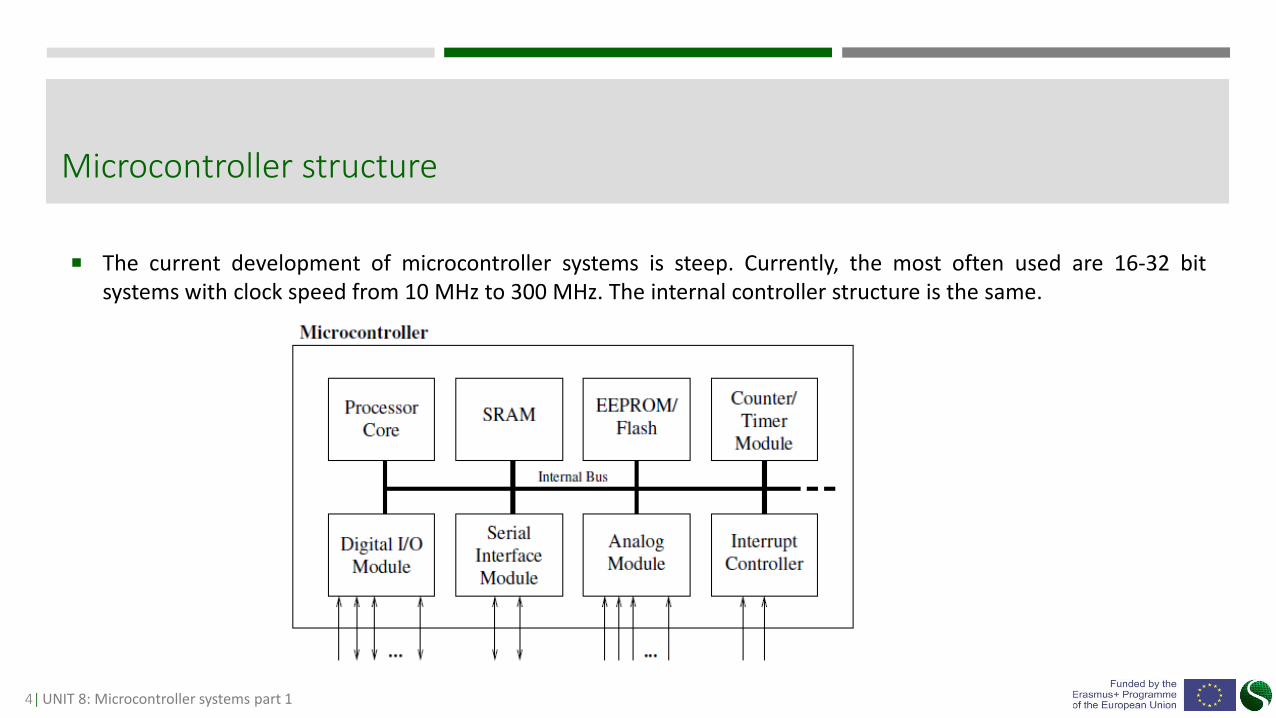
The current development of microcontroller systems is steep. Currently, the most often used are 16-32 bitsystems with clock speed from 10 MHz to 300 MHz. The internal controller structure is the same.
Microcontroller structure
5| UNIT 8: Microcontroller systems part 1
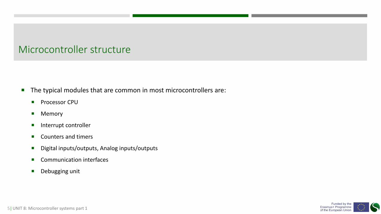
The typical modules that are common in most microcontrollers are:
Processor CPU
Memory
Interrupt controller
Counters and timers
Digital inputs/outputs, Analog inputs/outputs
Communication interfaces
Debugging unit
Microcontroller structure

6| UNIT 8: Microcontroller systems part 1
Processor core CPU is the main part of each microcontroller. Image 4 presents the basic processor structure.
Processor Core

7| UNIT 8: Microcontroller systems part 1
The core of the CPU consists of a data path (Data path), which executes the instructions from the control unit.The control units control the data path.
The core of the CPU is an arithmetic logical unit - an ALU capable of performing only basic computationaloperations such as; addition, subtraction and essential complement.
The task control unit (Control Unit) is to perform the instruction and determine which instruction will beperformed at a given moment. The control unit also stores the instruction index in the program counter-PC(Program Counter) and the contents of the instruction in the Instruction Register (IR).
The instruction determines which value from the registry will be sent to the ALU and where it will be stored.
Processor Core
8| UNIT 8: Microcontroller systems part 1
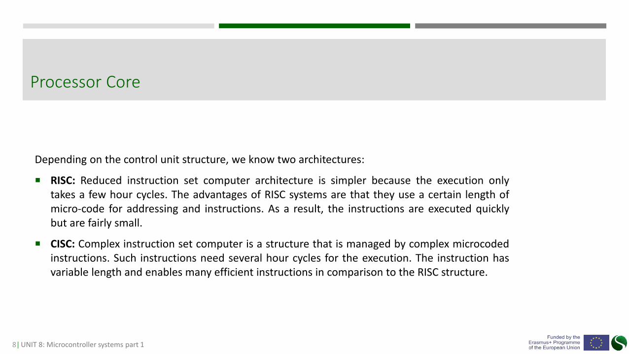
Depending on the control unit structure, we know two architectures:
RISC: Reduced instruction set computer architecture is simpler because the execution onlytakes a few hour cycles. The advantages of RISC systems are that they use a certain length ofmicro-code for addressing and instructions. As a result, the instructions are executed quicklybut are fairly small.
CISC: Complex instruction set computer is a structure that is managed by complex microcodedinstructions. Such instructions need several hour cycles for the execution. The instruction hasvariable length and enables many efficient instructions in comparison to the RISC structure.
Processor Core

9| UNIT 8: Microcontroller systems part 1
Depending on whether the memory is separate or common, we differentiate two types of processor architecture:
Von Neumann architecture: In this architecture, the instruction and datamemory is common. The bus that is used to access the memory is alsocommon. Unfortunately, in this architecture, it can lead to a conflictbetween the instruction and data which can cause unwanted system delay.This disadvantage is generally known as Von Neumann bottleneck.
Harvard architecture: In this architecture, the memories, as well as bus,are separate. The conflict between data and instruction is not possiblewhich consequently improves processor efficiency. The system’sdisadvantage is that the architecture needs several components, such asdouble memory, double bus and a unit that enables simultaneous access todata and instruction memory.
Processor Core
10| UNIT 8: Microcontroller systems part 1
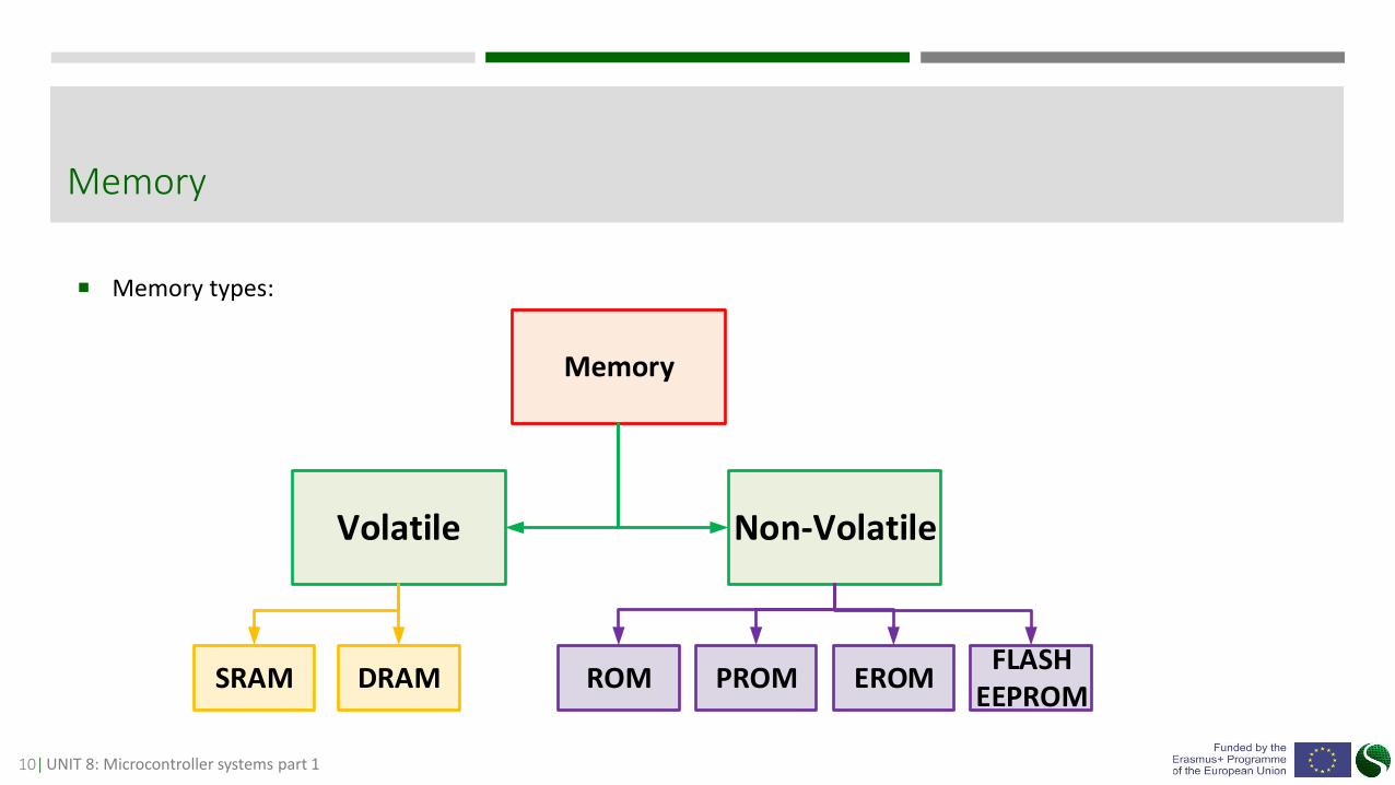
Memory types:
Memory
Memory
SRAM
Volatile Non-Volatile
DRAM ROM PROM EROMFLASH
EEPROM

11| UNIT 8: Microcontroller systems part 1
Static RAM-SRAM: Word RAM comes from the term random access memory, which means that we can accessthe memory locations randomly. SRAM memory for saving uses D-flip-flop cells. D-flip-flop is composed of atleast six transistors. Each D-flip-flop cell can save one bit (0 or 1), and each cell has address.
Volatile memory

12| UNIT 8: Microcontroller systems part 1
Dynamic RAM – DRAM: In comparison to SRAM, dynamicRAM reaches significantly higher capacities. Now we knowthat SRAM needs at least six transistors for saving 1 bit. Forthe higher capacity of SRAM, we need more cells whichsignificantly increases the physical chip size and price. If thememory can be reduced, we can use a simple way of savingbit value. DRAM saves data in electric charge storage(capacitor). This way the number of elements for saving onebit is reduced and consequently the capacity of memory isincreased at significantly smaller chip size. DRAM slower thanSRAM.
Volatile memory

13| UNIT 8: Microcontroller systems part 1
ROM: ROM stands for read-only memory. Read-only means that we cannot saveany data. ROM usually contains data saved by the manufacturer and are key fordevice functioning. In ROM is saved BIOS for personal computers or register valuesfor microcontroller settings.
PROM: ROM is used only in mass production because its production for smallerquantities or pilot research is too expensive. PROM (programmable read-onlymemory) is an alternative for ROM. It can be programmed only once because itcontains a fuse that prevents repeated writing. PROM is also known as OTP (one-time programmable memory). It is not suitable for development when memorycontent and the program often change.
Non-Volatile memory
14| UNIT 8: Microcontroller systems part 1
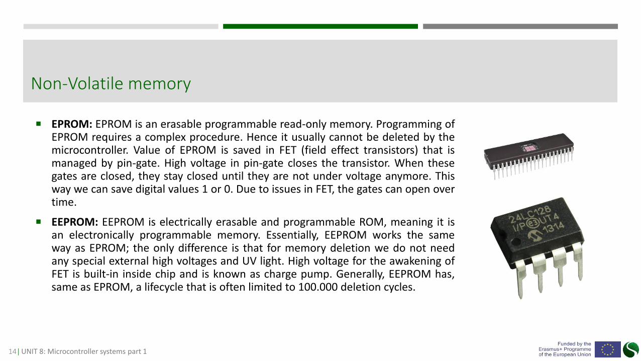
EPROM: EPROM is an erasable programmable read-only memory. Programming ofEPROM requires a complex procedure. Hence it usually cannot be deleted by themicrocontroller. Value of EPROM is saved in FET (field effect transistors) that ismanaged by pin-gate. High voltage in pin-gate closes the transistor. When thesegates are closed, they stay closed until they are not under voltage anymore. Thisway we can save digital values 1 or 0. Due to issues in FET, the gates can open overtime.
EEPROM: EEPROM is electrically erasable and programmable ROM, meaning it isan electronically programmable memory. Essentially, EEPROM works the sameway as EPROM; the only difference is that for memory deletion we do not needany special external high voltages and UV light. High voltage for the awakening ofFET is built-in inside chip and is known as charge pump. Generally, EEPROM has,same as EPROM, a lifecycle that is often limited to 100.000 deletion cycles.
Non-Volatile memory

15| UNIT 8: Microcontroller systems part 1
FLASH: FLASH is a limited version of EEPROM memory and works the same way asEEPROM. The difference between FLASH and EEPROM is that we cannot deleteeach cell separately, but only complete memory of a certain sector. The reason forthe implementation of FLASH memory is the high price of EEPROM memory.FLASH also has a limited number of sign-ins, same as EEPROM.
NVRAM: NVRAM (non-volatile RAM) is a combination of volatile and non-volatilememory. This memory has the same working principle as SRAM, but it has addedpower supply battery. We also know a version of memory, where EEPROM andSRAM memory are joined in the same chip.
Non-Volatile memory

16| UNIT 8: Microcontroller systems part 1
Digital inputs and outputs – I/O are used forcontrolling and management of external devices andare the main units inside the microcontroller.
Digital inputs and outputs are often grouped intoports. Each port can contain 8, 16 or 32 I/O pins.
Most often all I/O pins are two-way, meaning they canbe used as inputs or outputs.
Peripheral units-Digital inputs and outputs

17| UNIT 8: Microcontroller systems part 1
Analog inputs:
In comparison to the digital inputs and outputs, it is possible to read or process differentvoltage levels with analog inputs/outputs.
Reading of analog values is related to ADC peripheral unit in the controller. The basic dataof ADC converter are resolution, conversion speed, and conversion type.
Capturing of ADC signal is divided into three phases.
sample & hold
Kvantization
Coding
Peripheral units- Analog inputs

18| UNIT 8: Microcontroller systems part 1
Analog outputs:
The function of digital-analog converter DAC is to convert the binaryvalue to analog signal. DAC is most often used for processing of anyoutput signals from the controller. DAC has similar characteristics thanADC.
DAC resolution is defined by resolution (bit number) and samples persecond speed.
Peripheral units- Analog outputs
19| UNIT 8: Microcontroller systems part 1
Programs that are executed on microcontroller systems have to react to given events. The events differ by duration, whether they repeat and by complexity.
The controllers have to react to each potential change on the input pin, as well as receiving or transmission of data through communication interfaces.
Some most common interrupt routines:
Timer interrupt
Counter interrupt
External interrupt
Receive interrupt
Transmit interrupt
ADC interrupt
DAC interrupt
Sleep mode interrupt
Peripheral units- Interrupt routine

20| UNIT 8: Microcontroller systems part 1
Counters and timers are key peripheral units of each microcontroller that are often connected toother units. Timers are used for different tasks, such as delay, measurement of time, measurement offrequency. The most basic use of timers is use of the counter only. The timers can generate differentevents, interruption or process modulated PWM signal.
Main timer parameters:
Clock: Timer clock is determined by the speed of peripheral bus for the given timer. The speed of peripheral bus is determined by controller’s system settings.
Scaling factor (prescaler): Scaling factor determines timer clock split. With this factor, we determine timer increment and duration of counting when we count until the end of counters data register. Timer increment is time resolution that determines how precisely we measure time.
Period: Timer period determines counting time frame. This means that the longest period equals the length of the counter data register. Counter data length is determined by a number of bits in the timer.
Peripheral units- Counters and timers
21| UNIT 8: Microcontroller systems part 1
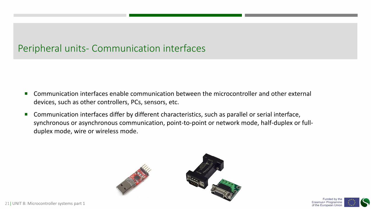
Communication interfaces enable communication between the microcontroller and other external devices, such as other controllers, PCs, sensors, etc.
Communication interfaces differ by different characteristics, such as parallel or serial interface, synchronous or asynchronous communication, point-to-point or network mode, half-duplex or full-duplex mode, wire or wireless mode.
Peripheral units- Communication interfaces

22| UNIT 8: Microcontroller systems part 1
USART: It is a serial connection (universal synchronous asynchronous receiver transmitter) that usesonly two lined for communication. One line is for transmitting Tx and other for receiving Rx. Thedifference between USART and UART is that USART needs a separate line for clock. UART has a presetclock with which are familiar all other devices in the communication path. In USART the receivingdevice uses sender’s clock. Image 13 presents UART communication interface.
Peripheral units- Communication interfaces
Adjustable parameters of USART serial interface are:
Number of data bits: Number of data bits determines how manybits will be captured in the sent data.
Parity bit: The user can decide if parity will be used or not. Paritycan be an even “1” or odd “0” bit. It is used as simple controlover communication regularity.
23| UNIT 8: Microcontroller systems part 1
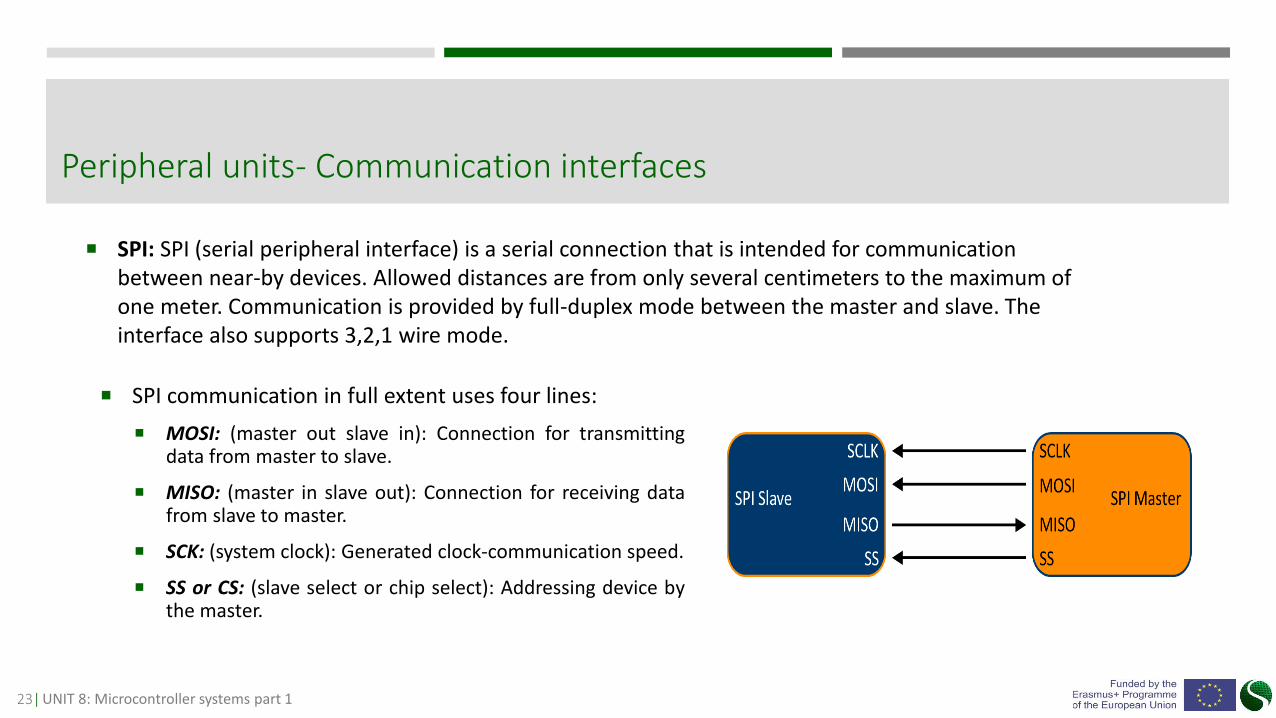
SPI: SPI (serial peripheral interface) is a serial connection that is intended for communication between near-by devices. Allowed distances are from only several centimeters to the maximum of one meter. Communication is provided by full-duplex mode between the master and slave. The interface also supports 3,2,1 wire mode.
Peripheral units- Communication interfaces
SPI communication in full extent uses four lines:
MOSI: (master out slave in): Connection for transmittingdata from master to slave.
MISO: (master in slave out): Connection for receiving datafrom slave to master.
SCK: (system clock): Generated clock-communication speed.
SS or CS: (slave select or chip select): Addressing device bythe master.
24| UNIT 8: Microcontroller systems part 1
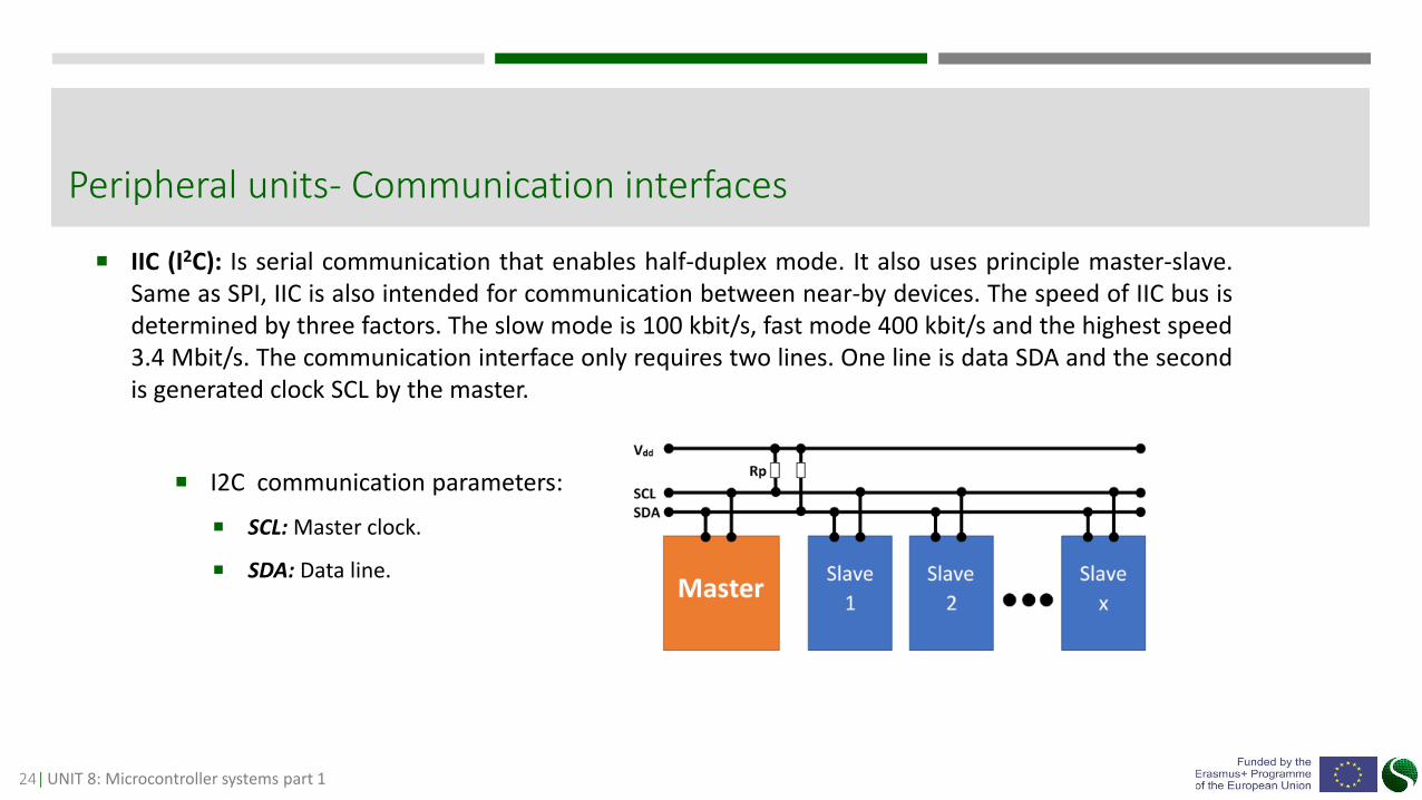
IIC (I2C): Is serial communication that enables half-duplex mode. It also uses principle master-slave.Same as SPI, IIC is also intended for communication between near-by devices. The speed of IIC bus isdetermined by three factors. The slow mode is 100 kbit/s, fast mode 400 kbit/s and the highest speed3.4 Mbit/s. The communication interface only requires two lines. One line is data SDA and the secondis generated clock SCL by the master.
Peripheral units- Communication interfaces
I2C communication parameters:
SCL: Master clock.
SDA: Data line.
25| UNIT 8: Microcontroller systems part 1
Each controller can be configurated in order to have the lowest possible consumption.
The first step to ecological design requires choosing a controller depending on its characteristics and chipsize. The chip size is directly related to used chip materials, such as housing plastic, metal pins or silicon.
For each device or application, it is important to evaluate which controller we will use. On the market areseveral controllers that are intended for low consumption and long autonomy.
Software and hardware parameters:
Controller clock
Supply voltage
Switching off unused modules
Optimal code design
Sleep and standby mode
Guidelines for low energy consumption of microcontrollers and ecological aspects