the potential for stress corrosion cracking of copper
TRANSCRIPT

AECL EACL
CA9700701
AECL-11550, COG-96-94
The Potential for Stress Corrosion Cracking of Copper Containers in a Canadian Nuclear Fuel Waste Disposal Vault
La possibility de fissuration par corrosion sous contrainte des conteneurs en cuivre dans une installation de stockage permanent des dechets de combustible nucleaire canadien
F. King
September 1996 septembre

AECL
THE POTENTIAL FOR STRESS CORROSION CRACKING OF COPPER CONTAINERS IN A CANADIAN NUCLEAR FUEL WASTE DISPOSAL VAULT
by
F. King
Whiteshell Laboratories Pinawa, Manitoba, Canada ROE 1L0
1996AECL-11550
COG-96-94

AECL EACL
THE POTENTIAL FOR STRESS CORROSION CRACKING OF COPPER CONTAINERS IN A CANADIAN NUCLEAR FUEL WASTE DISPOSAL VAULT
by
F. King
ABSTRACT
The potential for stress corrosion cracking (SCC) of copper nuclear fuel waste containers in a conceptual Canadian disposal vault has been assessed through a review of the literature and comparison of those environmental factors that cause SCC with the expected disposal environment. Stress-corrosion cracking appears to be an unlikely failure mode for Cu containers in a Canadian disposal vault because of a combination of environmental factors. Most importantly, there is only a relatively short period during which the containers will be undergoing strain when cracking should be possible at all, and then cracking is not expected because of the absence of known SCC agents, such as NH3, NOj or organic acids. In addition, other environmental factors will mitigate SCC, namely, the presence of Cl and its effect on film properties and the limited supply of oxidants. These arguments, to greater or lesser extent, apply to the three major mechanisms proposed for SCC of Cu alloys in aqueous solutions: film- rupture/anodic dissolution, tarnish rupture and film-induced cleavage.
Detailed reviews of the SCC literature are presented as Appendices. The literature on the SCC of Cu (>99 wt.% Cu) is reviewed, including studies carried out in a number of countries under nuclear waste disposal conditions. Because of similarities with the behaviour of Cu, the more extensive literature on the SCC of a-brass in ammonia solutions is also reviewed.
Atomic Energy of Canada Limited Whiteshell Laboratories
Pinawa, Manitoba ROE 1L0 1996
AECL-11550COG-96-94

AECL EACLA
LA POSSIBELITE DE FISSURATION PAR CORROSION SOUS CONTRAINTE DES CONTENEURS EN CUIVRE DANS UNE INSTALLATION DE STOCKAGE PERMANENT
DES DECHETS DE COMBUSTIBLE NUCLEAIRE CANADIEN
par
F. King
RESUME
On a evalue, a partir de la documentation et de la comparaison des facteurs environnementaux qui provoquent la fissuration par corrosion sous contrainte, la possibility de fissuration par corrosion sous contrainte des conteneurs en cuivre de dechets de combustible nucleaire dans une installation conceptuelle de stockage permanent au Canada. H semble peu probable que la fissuration par corrosion sous contrainte soit un mode de rupture des conteneurs en cuivre dans une installation de stockage permanent canadienne en raison des differents facteurs environnementaux. Plus important encore, c’est uniquement pendant une periode de temps relativement courte que les conteneurs pourraient se Assurer, et on ne s’attend pas a ce que cette fissuration soit possible par la suite, en raison de 1’absence d’agents connus de fissuration par corrosion sous contrainte, notamment le NH3, le NH2 ou les acides organiques. De plus, d’autres facteurs environnementaux viendront attenuer la fissuration par corrosion sous contrainte, notamment la presence de Cl et ses effets sur les proprietes du film et la quantity limitee d’oxydants. Ces variables, dans une plus ou moins large mesure, s’appliquent a trois mecanismes importants proposes pour la fissuration par corrosion sous contrainte des alliages de cuivre en solutions aqueuses : rupture du film/dissolution anodique, rupture par temissement et clivage cause par le film.
L’analyse detaillee de la documentation sur la fissuration par corrosion sous contrainte est presentee en annexes. On analyse la documentation sur la fissuration par corrosion sous contrainte du cuivre (>99 % en poids de Cu), notamment les etudes sur le stockage permanent des dechets de combustible nucleaire realisees par d’autres pays. H est aussi question de la documentation exhaustive sur la fissuration par corrosion sous contrainte du laiton alpha dans des solutions ammoniaques en raison des similitudes de comportement avec le cuivre.
Energie atomique du Canada limitee Laboratoires de Whiteshell
Pinawa (Manitoba) ROE 1L0 1996
AECL-11550COG-96-94

CONTENTS
Page
1. INTRODUCTION 1
2. STRESS CORROSION CRACKING MECHANISMS 1
2.1 FILM-RUPTURE/ANODIC DISSOLUTION MODEL 22.2 TARNISH-RUPTURE MODEL 42.3 FILM-INDUCED CLEAVAGE MODEL 62.4 SURFACE-MOBILITY MODEL 8
3. THE POTENTIAL FOR SCC OF COPPER CONTAINERSIN A CANADIAN NUCLEAR WASTE DISPOSAL VAULT 10
3.1 ARGUMENTS BASED ON THE ENVIRONMENT 103.1.1 Material Properties 103.1.2 Loading Conditions 123.1.3 Absence of SCC Agents 133.1.4 Lack of Oxidants and Effect on ECORR 173.1.5 Effect of Chloride and Film Properties 20
3.2 MECHANISTIC ARGUMENTS 213.2.1 Film-rupture/Anodic Dissolution Model 223.2.2 Tarnish-rupture Model 233.2.3 Film-induced Cleavage Model 23
4. CONCLUSIONS AND FUTURE WORK 25
ACKNOWLEDGEMENT 26
REFERENCES 26
TABLES 34
FIGURES 37
APPENDIX A STRESS CORROSION CRACKING OF COPPER 53
A.l REVIEW OF LITERATURE 53A. 2 SCC STUDIES SPECIFICALLY RELATED TO
NUCLEAR WASTE CONTAINERS 57
APPENDIX B STRESS CORROSION CRACKING OF a-BRASSIN AMMONIA SOLUTIONS 64
B. l GENERAL CONSIDERATIONS 64B.2 MECHANISM OF INTERGRANULAR SCC 69B.3 MECHANISM OF TRANSGRANULAR SCC 70

1. INTRODUCTION
Oxygen-free copper has been proposed as a container material for the disposal of used nuclear fuel in a vault located deep underground in the granitic rock of the Canadian Shield (Johnson et al. 1996). Corrosion is one possible mechanism that could lead to failure of the containers and contact of the used fuel with groundwater. It is necessary, therefore, to be able to predict the corrosion behaviour of the containers over extended periods of time. Mathematical models have been developed to predict the long-term effects of uniform corrosion and pitting, the only two modes of corrosion that are expected to occur (King and Kol&r 1995, 1996; Kolar and King 1996a,b). Other corrosion mechanisms, such as stress-corrosion cracking (SCC) or crevice corrosion, are considered unlikely. For such processes, it is necessary to develop sound mechanistic arguments why these forms of corrosion will not lead to container failure.
Typical stress corrosion crack-growth rates in Cu alloys are between 10"6 and 10"9 m s'1 (Appendices A and B), and would result in through-wall cracks in 25-mm-thick Cu containers in between 7 h and 300 d. Therefore, it is necessary to demonstrate that cracks will either not initiate for the lifetime of the container or that the conditions necessary for their propagation will not exist. The emphasis in this review will be on demonstrating that the conditions necessary for crack growth will not exist in the disposal vault. Given the long timescales of interest in nuclear waste disposal, it is generally easier to argue that propagation will be limited, rather than to argue that cracks will not initiate. In particular, the effect of environmental conditions on crack propagation will be considered in detail.
There has been much work on the SCC of Cu (>99 wt.% Cu) and the associated phenomenon of the SCC of a-brass in ammonia solutions. The bulk of the literature review of these topics is presented in Appendices A and B, with only a brief summary of the various proposed mechanisms described here. In the major part of the main text, the arguments against the SCC of Cu containers in a Canadian disposal vault are presented.
2. STRESS CORROSION CRACKING MECHANISMS
Several models have been proposed for the SCC of Cu and brass in various solutions. Of these, the three that have found the widest acceptance are the film-rupture/anodic dissolution model, the tarnish-rupture mechanism and the film-induced cleavage model. A fourth, the surface- mobility mechanism, has been proposed to describe the SCC of a wide range of materials, including Cu alloys, but has not gained wide support.
In general, crack propagation is the result of a sequence of processes, any one of which can be rate-determining (Jones and Ricker 1992). The most obvious requirement for SCC is the presence of a tensile stress. Stress, or perhaps, more importantly, the strain that it produces, can have a number of effects, depending upon the mechanism of crack growth, as described for the various models below. Other possible rate-controlling processes are illustrated in Figure 1 (Jones and Ricker 1992) (i)
(i) mass transport by diffusion and/or migration along the crack to or away from the crack

-2-
tip,(ii) homogeneous reactions in the solution,(iii) electron-transfer processes on the surfaces outside the crack, on the crack walls or at the
crack tip,(iv) film formation on the crack walls or at the crack tip,(v) adsorption of species near the crack tip,(vi) surface diffusion,(vii) surface reactions,(viii) adsorption of species into the metal,(ix) solid-state diffusion to the plastic zone ahead of the advancing crack,(x) chemical reactions within the metal, and(xi) the rate of interatomic bond rupture.
Not all of these processes will be important for any given SCC mechanism. In determining whether SCC of Cu containers will occur, it is necessary to identify which of these steps are important and to predict how the environmental conditions within the vault will affect the rates of these processes. No judgement is made here regarding the validity of the various proposed mechanisms, except that less attention is given to the surface-mobility model.
The environments in which the SCC of Cu and a-brass has been reported are summarized in Tables 1 and 2, respectively, along with the proposed mechanism(s).
2.1 FILM-RUPTURE/ANODIC DISSOLUTION MODEL
In the film-rupture/dissolution model, crack advance occurs by anodic dissolution at the bare crack tip following rupture of a protective film. The sides of the crack are protected against dissolution by the presence of the film. Classically, SCC via this mechanism is characterized by continuous crack advance, smooth fracture surfaces and crack-growth rates consistent with Faraday's law and a suitable crack-tip current density. Continuous crack advance requires that the crack tip is maintained in a film-free condition by continual rupture of the film (Figure 2(a)). Film rupture may occur either because the crack-tip strain exceeds the fracture strain of the film or if slip occurs along a slip plane and the slip-step height exceeds the film thickness. There is no reason, however, why crack advance cannot be discontinuous if the film growth rate exceeds the rate of rupture. Cracking could then proceed by a series of discrete film-rupture and dissolution/repassivation steps (Figure 2(b)). The critical parameters in determining the length of crack extension between repassivation steps are the dissolution and repassivation kinetics of the material in the environment, and the rate of exposure of bare metal at the crack tip. The most severe cases of SCC via dissolution mechanisms generally occur when the repassivation step is slow, thus allowing propagation at the crack tip by dissolution, but eventually occurs, thus protecting the crack walls (Newman and Burstein 1980).
Film-rupture/dissolution models can account for both intergranular (IGSCC) and transgranular SCC (TGSCC). In the former, segregation of impurities to grain boundaries may either increase

-3-
the rate of dissolution or, alternatively, inhibit repassivation at these locations. Cracking would then naturally occur at the grain boundary, and once initiated the concentration of stress at the crack tip would favour continued intergranular penetration. On the other hand, transgranular penetration is also consistent with this model, especially for pure metals where there would be no tendency for preferential grain-boundary dissolution.
Dissolution models have been proposed for the SCC of Cu in a number of environments. Both Pednekar et al. (1979) and Uchida et al. (1991) suggest film-rupture/dissolution models for the TGSCC of Cu in N02 solutions. Yu and Parkins (1987) and Wu et al. (1991) also appear to favour a dissolution model to describe the TGSCC of Cu in N02 solutions, although they do not unequivocally rule out a model based on film-induced cleavage (Chapter 2.3). Escalante and Kruger (1971) suggest a tarnish-rupture model (Chapter 2.2), but comment on the formation of bare metal due to oxide rupture, which is consistent with a dissolution mechanism. Slip/dissolution and film-rupture/dissolution models have also been suggested for the IGSCC of a-brass in ammonia solutions (Pugh 1979; Bertocci et al. 1990). Unfortunately, it is not unequivocally stated in the literature whether this mechanism applies to a-brass in both tarnishing solution (in which cracking of annealed specimens is invariably intergranular) and non-tarnishing solutions (in which IGSCC is only observed for Zn contents < 18 wt.%). The important point here is that pure Cu does not crack in tarnishing solutions but does undergo IGSCC under non- tarnishing conditions, in exactly the same manner as brasses of low Zn content (Figure 3). On the assumption that all IGSCC of brasses is a result of a film-rupture/dissolution mechanism, as is implied in the literature, it appears that the IGSCC of both pure Cu in non-tarnishing ammonia and dilute Cu-P alloys in tarnishing ammonia atmospheres (Thompson and Tracy 1949) may be the result of film-rupture followed by crack advance by anodic dissolution at the crack tip.
The crack velocity (v) for a dissolution-controlled process is given by Faraday's law (Parkins 1987)
v - iCT(M/zFp) (1)
where iCT is the anodic current density at the crack tip, M is the atomic mass of the metal, z is the valency of dissolved metal, F the Faraday constant and p is the density of the metal. Equation (1) represents the upper bound of the dissolution rate, and corresponds to the situation where the crack tip is maintained film-free by a sufficient crack-tip strain rate or because of slow repassivation kinetics. Lower rates than those predicted by Equation (1) are possible if discontinuous cracking occurs as a result of repassivation at the crack tip.
For situations in which the film is not continuously ruptured, the crack velocity is given by (Parkins 1987)
v =£c
CT
MzFp
(2)

-4-
where QF is the charge density passed between rupture events, ec is the critical strain for film rupture and £CT is the crack-tip strain rate.
The various factors that might control the rate of crack propagation via a dissolution mechanism can be determined from Equations (1) and (2). In both cases, the crack-tip strain, rather than the tensile stress, is the important mechanical parameter; for continuous crack growth (Equation 1), the crack-tip strain rate must be sufficiently high to maintain a bare surface at the crack tip and, for discontinuous crack advance (Equation 2), crack-tip strain is required to rupture the (oxide) film.
The role of the chemical environment in the film-rupture/dissolution model is mainly through the terms iCT and QF in Equations (1) and (2). The solution must support rapid anodic dissolution and be able to maintain film-free conditions at the crack tip to allow for crack advance via dissolution of the metal. Crack-tip current densities are of the order of several A cm'2 (Pugh 1979). Rapid dissolution is observed in solutions containing complexing species, such as NH3. Rapid dissolution also requires that the mass transport of the complexant into the crack is fast. Because NO; does not form complexes with Cu(I) or Cu(II), Cole et al. (1988) have suggested that a dissolution mechanism is unlikely in NO; solutions, unless NO; is reduced to NH3 at negative potentials at the crack tip (Newman and Burstein 1980). (For Cu, it is unlikely that the potential will be sufficiently negative within the crack to reduce NO; to NH3, although this may be feasible for brass, for which the preferential dissolution of Zn may cause cathodic shifts in potential (Bertocci and Pugh 1987)).
Rapid anodic dissolution at the crack tip must be supported by an equally rapid cathodic reaction, occurring either on the crack walls or on surfaces outside the crack. (However, the cathodic surface area is likely to be higher, so that the cathodic current density will be lower than the anodic current density). If the transport of oxidant into the crack is fast, dissolution at the crack tip could be supported by cathodic reactions occurring on the crack walls. However, dissolution on the crack walls could also occur, leading to crack blunting. Alternatively, the reduction of oxidant on external surfaces could support anodic dissolution at the crack tip, with the sides of the crack protected by film formation. In this case, however, the crack-tip potential (ECT) would differ from the potential on the external surface and crack growth could be stifled by excessive iR drop down the crack.
Whilst sustaining anodic dissolution at the crack tip, the environment must also sustain film formation to protect the walls of the crack from dissolution. The most likely type of film is an oxide layer, suggesting neutral to alkaline conditions within the crack, unlike the acidic conditions usually encountered in pits and crevices. In turn, this suggests that acidification via hydrolysis reactions is suppressed, possibly because of complexation of dissolved Mn+.
2.2 MODEL
Tarnish-rupture models have long been associated with the SCC of Cu alloys, primarily because

-5-
of the importance initially attached to the correlation between the SCC of a-brass in ammonia and the formation of a visible tarnish film (Figure 4). Crack advance occurs by the rupture of the tarnish film (Figure 2(c)), and is followed by a period during which the tarnish layer reforms. The key feature of the tarnish-rupture mechanism is that cracking is limited to the thickness of the tarnish film. Cracking is discontinuous, with periods of rapid crack advance interspersed by longer periods of tarnish growth. Pinchback et al. (1975), however, showed that the tarnish film is not present at the crack tip for a-brass in tarnishing ammonia solution, which has tended to discredit tarnish-rupture models.
The properties and structure of the tarnish layer that forms on a-brass in ammonia solution have been studied in some detail (Appendix B.l). The layer forms above a certain critical [Cu(II)] (Figure 4), the exact value of which depends on the pH and ammonia concentration. Experimentally, tarnish formation corresponds with an increase in the open-circuit potential of the a-brass sample, a decrease in the dissolution rate and a switch from TGSCC to IGSCC. The structure of the tarnish layer is shown in Figure 5. A thin (20 nm for brass, 10 nm for Cu) epitaxial layer of CuzO grows at the interface, via a solid-state process (Pugh 1979). Breakdown of this film leads to rapid dissolution through the defects and the precipitation of a thicker (up to several tens of pm), porous Cu20 layer. Upon extended exposure, the outer part of the porous layer is oxidized to CuO.
The tarnish could grow preferentially at grain boundaries, leading to IGSCC, or form uniformly over the surface, in which case TGSCC could occur. Suzuki and Hisamatsu (1981) show photomicrographs that suggest a fairly uniform surface coverage by the tarnish, and report transgranular cracking.
Rupture of an adherent tarnish film has been proposed for the TGSCC of Cu in dilute ammonia (Suzuki and Hisamatsu 1981). Unlike Pinchback et al. (1975), Suzuki and Hisamatsu (1981) observed oxide at the crack tip. Escalante and Kruger (1971) also proposed a tarnish-rupture model for the IGSCC of Cu in acetate solutions, although the details of their mechanism are also consistent with a film-rupture/dissolution mechanism. Historically, the IGSCC of a-brass in ammonia solutions was described in terms of a tarnish-rupture mechanism (Pugh et al. 1969), but, following the observations of Pinchback et al. (1975), this has been superseded by the film- rupture/dissolution model described above.
The rate of cracking can be predicted if the fracture strain and growth kinetics of the tarnish layer are known. For the parabolic Cu20 growth kinetics observed by Suzuki and Hisamatsu (1981) in dilute ammonia solutions, the crack velocity is given by
v - 0.5C(fecr/ec)u2 (3)
where C is a constant determined by the tarnish-growth kinetics. Comparison of Equations (2) and (3) shows that, whilst the discontinuous film-rupture/dissolution and tarnish-rupture models may be conceptually similar, the former predicts a linear dependence of v on 6CT, whereas the latter predicts a square-root relationship (or cube-root in the case of cubic tarnish-growth

-6-
kinetics). Suzuki and Hisamatsu (1981) found good agreement between observed and predicted failure times based on Equation (3).
As with the dissolution model, the crucial mechanical factor in the tarnish-rupture model is the crack-tip strain rate rather than the stress, although, of course, the two are linked. Also of importance is the fracture strain of the film. Figure 6 shows the £<- values for Cu20 films grown on pure Cu in 0.05 and 0.06 mol-dm"3 NH4OH at various potentials measured by Suzuki and Hisamatsu (1981) and the data reported by Yu et al. (1987) for films grown on a-brass in 1 mol dm"3 NaN02 at pH 9. Suzuki and Hisamatsu found relatively little effect of potential and no difference between Cu and brass. The data of Yu et al. (1987) show an exponential decrease in fracture strain with potential. In general, however, ec is of the order of 0.001 for Cu20. The environment could affect the rate of tarnish rupture through the effect of potential, or other environmental factors (such as the presence of Cl"), on ec.
The environment is also important in determining the rate of tarnish growth. For a given ec, the crack velocity is higher the larger the rate of tarnishing (i.e., the higher the value of C in Equation (3)). Thus, at a given strain rate, the rate of SCC via a tarnish-rupture mechanism is highest at the potential corresponding to the maximum tarnish-growth rate. Tarnish formation may be favoured at higher pH or in certain electrolytes. Figure 7 shows the relative rates of Cu20 formation in aerated 0.05 mol dm"3 NH4OH and aerated 0.5 mol dm"3 NaCl. The rate of oxide growth is approximately 30 times faster in the ammonia solution. In addition to these effects on the anodic reaction, the cathodic reaction may also play a role by shifting EC0RR into the correct potential range for rapid tarnish growth.
2.3 FILM-INDUCED CLEAVAGE MODEL
In the film-induced cleavage model a brittle crack initiates in a thin surface layer, and induces a cleavage-like crack in, what otherwise would be, the ductile underlying metal (Newman and Sieradzki 1983; Sieradzki and Newman 1985). The length of the cleavage crack is typically 10 to 100 times the length of the crack in the surface layer (Figure 2(d)). This SCC mechanism is unique, in that electrochemical reactions are only involved in the formation of the initiating layer, whilst the vast majority of the crack advance (the cleavage crack) is independent of any anodic or cathodic process. Other unique features of this mechanism are that it can account for the cracking of a-brass in ammonia solutions under conditions in which there is no net dissolution of Cu (Bertocci et al. 1984; Shahrabi et al. 1993) and that the formation of a protective oxide on the crack walls is not a prerequisite.
Crack propagation is discontinuous, with periods of crack arrest interspersed by crack advance at velocities almost the speed of sound. The discontinuous nature of the cracking process has been confirmed by acoustic emission and electrochemical noise measurements which have been linked to the formation of the cleavage cracks (Newman and Sieradzki 1983; Sieradzki and Newman 1985), and by marking the position of the crack tip by periodic load pulses and observing the pattern of these marks on the fracture surface (Bertocci et al. 1990).

-7-
Central to the film-induced cleavage model are the nature and properties of the initiating layer. For a-brass, the evidence suggests that the layer is a microporous region formed by the preferential dissolution (dealloying) of Zn (Sieradzki et al. 1987; Newman et al. 1989; Bertocci et al. 1990; Shahrabi et al. 1993). Similar dealloyed layers are believed to be responsible for film-induced cleavage in Cu-Al and Cu-Au alloys (Sieradzki et al. 1987; Cassagne et al. 1988). The identity of the initiating layer in Cu has received less attention. An obvious candidate is a thin epitaxial Cu20 layer, similar to the thin (10-20 nm) Cu20 layer that forms directly on the Cu surface during tarnishing in ammonia solutions (Figure 5). Cassagne (1989) has suggested that crack initiation is not associated with the fracture of this film, but with the breakdown of the film via a micropitting process. Presumably, extensive micropitting of the Cu20 layer would produce a microporous film, similar to the porous dealloyed layers in a-brass. An alternative, but somewhat singular, type of film was identified by Sieradzki and Kim (1992). A combination of dynamic straining and rapid dissolution can lead to the formation of a uniformly porous layer of etch pits that are completely film-free. It is suggested that this layer is responsible for the film-induced cleavage of Cu in non-tarnishing ammonia solutions (Sieradzki and Kim 1992).
Cracking occurs transgranularly along preferential {110} planes. Fracture surfaces appear to be cleaved in a brittle manner and exhibit flat primary facets in the {110} plane separated by steps. Opposite surfaces match perfectly. The crack radiates in a fan-like pattern from the site of initiation and crack-arrest markings can be observed, with a typical spacing of -1 pm for Cu-30Zn in ammonia solutions and an interval between crack events of -10 s (Bertocci et al. 1990).
The proponents of the film-induced cleavage model have applied it to a number of cases of the TGSCC of pure Cu, as well as to a-brass in non-tarnishing ammonia and N02 solutions. Thus, Sieradzki et al. (1984) suggested that the cracking of Cu in N02 solutions was consistent with film-induced cleavage. This suggestion was supported by the work of Cassagne et al. (1990) who proposed the same mechanism for the TGSCC of Cu in both N02 and sodium acetate solutions. As mentioned above, Sieradzki and Kim (1992) have also proposed film-induced cleavage for a very specific form of TGSCC of Cu in non-tarnishing ammonia that is only observed at relatively high strain rates (> 1 x 10 s s ').
Yu and Parkins (1987) have derived a simple expression for the crack velocity for the film- induced cleavage model
v = -j + L1£C ^ E CT
(4)
where j is the length of the cleavage crack in the underlying metal and L' is the thickness of the initiating layer. Since j » L\ the critical parameters in Equation (4) are j and the time between fracture events (ec/6CT).
It can be seen from Equation (4) that, in common with the dissolution and tarnish-rupture models

-8-
described above, the crack-tip strain rate is an important parameter in determining the extent of crack advance via a film-induced cleavage mechanism. For a given film strength, determines the time between fracture events. Furthermore, dynamic strain is required for the film-induced cleavage of Cu, although not for a-brass. When Cu specimens are held under constant displacement (approximately constant load) conditions, cracking stops within 20 pm (Sieradzki et al. 1984). The steps between successive cleaved facets on fracture surfaces on Cu are found to be more load-bearing than the equivalent steps in a-brass. These load-bearing steps are apparent on the fracture surfaces as ductile regions characterized by necking (Sieradzki et al. 1984), as opposed to the crystallographic appearance of steps between the facets on a-brass fracture surfaces.
The role of the environment and anodic and cathodic reactions is somewhat different for the film- induced cleavage model than for either the film-rupture/dissolution or tarnish-rupture models. The environment must be suitable for the formation of the initiating layer but, since the identity of this layer has not been clearly established for Cu, it is difficult to identify those environments that might be suitable for cracking via this mechanism. If the initiating layer is a film-free etch- pitted layer, the environment must be suitable for sustaining rapid dissolution without film formation, as in the non-tarnishing ammonia solutions used by Sieradzki and Kim (1992). Alternatively, if the initiating layer is either a Cu20 film or a pitted Cu20 layer (Cassagne 1990), a film-forming environment would be necessary.
Unlike the two film-rupture models, the majority (90-99%) of the crack propagation step does not require an accompanying electrochemical process. (The value of the fraction noted above depends on the relative values of j and L1, Equation (4)). Anodic and cathodic reactions are required to form the initiating layer, and it may become apparent upon further study that there are certain requirements necessary for crack initiation, e.g., a threshold dissolution rate or potential. At this stage, however, there is scant evidence for such prerequisites for Cu, although film-induced cracking does appear to be associated with systems in which the general dissolution rate is high. For instance, the TGSCC of a-brass occurs in non-tarnishing solution, in which the general dissolution rate is not inhibited by film formation (Figure 4(b)). In addition, Sieradzki and Kim (1992) did not observe TGSCC of Cu in such solutions at uniform dissolution rates less than 350 pm a"1 (equivalent to a current density of 15 pA-cm2), regardless of the strain rate.
2.4 MODEL
Although never reported for Cu in aqueous solution, it has been suggested that Cu and Cu alloys should be susceptible to SCC via a surface-mobility mechanism (Galvele 1987). According to the surface-mobility model, SCC (as well as liquid metal embrittlement and hydrogen embrittlement) is caused by the removal of atoms (or the introduction of vacancies) at the crack tip. At temperatures below 0.5Tm (where Tm is the melting point), the most effective mechanism for the removal of atoms from (or of addition of vacancies to) the crack tip is surface diffusion. The crack velocity is given by (Galvele 1987)

-9-
( 3 \□a-1exp l kT J (5)
where Ds is the surface self-diffusion coefficient, L" is the diffusion distance of the atoms (or vacancies), o is the elastic surface stress at the crack tip, a is the atomic size, k Boltzmann's constant and T the absolute temperature. The distance L" depends on the distance the atom has to diffuse before encountering a surface defect such as a kink site, but is less than the distance between two ledges on a surface terrace. Galvele (1987) has proposed that the surface-mobility mechanism can account for a number of environmentally assisted cracking phenomena for a range of alloys in various environments.
Galvele (1987) proposed the use of an empirical expression relating the temperature dependence of Ds for metals in vacuo or in gas atmospheres to Tm. (There is a lack of Ds data in aqueous solutions in the literature). The value of Ds is modified by surface compounds; increasing if the melting point of the compound is less than that of the metal and decreasing if the compound has a higher melting point. The value of Ds in Equation (5) depends on the surface coverage by the compound and, therefore, is a function of the environment and E. Consequently, a metal has both an intrinsic susceptibility to SCC because of the mobility of atoms in the absence of modifying surface layers and a specific susceptibility due to the modification of Ds through the formation of surface compounds. Galvele (1987) listed the Tm values for a number of compounds for 27 metals and found that those with low melting points were generally those found to cause SCC, whilst those with high melting points tended to be protective. For Cu, the compounds with low melting points include Cu(C103)2-6H20, Cu(C104)2-6H20, Cu(NH3)4(N02)2, Cu(NH3)2Cl2 and CuCl and those with high melting points were Cu20 and CuO.
Equation (5) is capable of accounting for the effect of a number of environmental factors on SCC. As mentioned above, v is a function of E and the environment due to the effect of coverage by surface layers on Ds. The environment and E may also affect L" because a surface species may diffuse a different distance on a surface that is generally dissolving than on a passive surface. The effect of stress is accounted for through the o term. Unlike the previous three mechanisms discussed, however, it is the stress, rather than the crack-tip strain rate, that is the important factor in the surface-mobility mechanism. One feature of this model is that the crack velocity of a stressed metal always has a finite value. Thus, although Galvele (1987) proposed that crack velocities < 0.01 nm s ' should be considered "safe" in the sense that they would not lead to failure on practical timescales, such a definition cannot be applied to the SCC of a nuclear waste container that is required to remain intact for thousands of years.
The greatest argument against the surface-mobility model, however, is its inability to quantitatively predict crack velocities. According to the model, Cu has an intrinsic susceptibility to SCC in pure water which, for typical values of L" and o, would produce a value of v of 23 nm s' at 100°C. This crack velocity is higher than the maximum rate observed for Cu in 1 mol-dm"3 NaN02 at 25°C (Yu and Parkins 1987), an extremely aggressive environment.

-10-
Furthermore, Equation (5) predicts a crack velocity of 2.2 mm s ' at 100°C when covered by a surface layer of CuCl and even higher rates for surfaces covered by Cu(C103)2-6H20, Cu(C104)2-6H20, Cu(NH3)4(N02)2 and Cu(NH3)2C12, which have lower melting points than CuCl. Such rates are clearly not observed in practice, although the relative Tm values do qualitatively account for the increased susceptibility of Cu alloys to SCC in N02 and NH3 compared with Cl" environments.
Galvele and coworkers have argued that the surface-mobility model can best explain the observed SCC behaviour of a number of Cu alloys. Rebak et al. (1988) suggested that the SCC of a-brass in NaNOz was more consistent with a surface-mobility mechanism than the film-induced cleavage model (Sieradzki and Newman 1985). An adsorbed surface layer of Cu(NOz)2 was proposed to increase the surface mobility. Similarly, Rebak and Galvele (1989) favoured a surface-mobility model over an anodic dissolution mechanism to describe the SCC of a-brass in Na5P3O10 and Na4P2G7. The only application to pure Cu has been in CuCl/Ar gas mixtures at 200°C (Bianchi and Galvele 1993). A maximum crack velocity of 1.4 nm-s"1 was reported at 200°C, six orders of magnitude slower than the rate predicted by Equation (5) at a temperature of 100°C. There are no reports of SCC of Cu by a surface-mobility mechanism in aqueous solution.
In conclusion, although the surface-mobility model is capable of qualitatively accounting for many of the observed trends in SCC behaviour for a number of SCC systems, the large discrepancy between predicted and observed crack growth rates must be resolved before this mechanism can be considered to be a reliable indicator of SCC behaviour.
3. THE POTENTIAL FOR SCC OF COPPER CONTAINERS IN A CANADIANNUCLEAR WASTE DISPOSAL VAULT
No detailed study of the conditions necessary for SCC of Cu under Canadian disposal conditions has been performed. Nevertheless, it is possible to draw certain conclusions from the mechanisms presented above. In this chapter, specific arguments against the possibility of SCC of Cu containers will be presented, first in terms of the specific container materials and environmental conditions for the Canadian concept and then in terms of the three main mechanisms proposed for the SCC of Cu. No judgement is made here regarding the appropriateness of any of the mechanisms, except that the surface-mobility model will not be considered because of the large discrepancy between predicted and observed crack velocities.
3.1 ARGUMENTS.
3.1.1
The coppers (UNS C10100 to UNS Cl5760) are some of the more resistant Cu alloys to SCC. Most of the experimental program in Canada has focussed on the corrosion behaviour of oxygen- free electronic (OFE) Cu (UNS Cl0100), although the reference material for a recent assessment

-11-
study (Johnson et al. 1996) is an experimental Finnish alloy, deoxidized low-phosphorus (DLP) Cu, chosen for its superior creep properties. This material is actually OFHC Cu to which a small amount of P (0.005 wt.%, 50 ppm) is added during manufacture (J.L. Crosthwaite, private communication), and should not be confused with the phosphorus-deoxidized (PDO) Cu alloys (UNS Cl2000 to UNS Cl2300). The addition of P improves the creep ductility of the material and increases the creep strain at which failure occurs (Henderson et al. 1992). Phosphorus- containing alloys, however, have been shown to be marginally more susceptible to IGSCC in tarnishing ammonia atmospheres than pure or OFF Cu (Figure 8, Thompson and Tracy 1949). The experimental DLP alloy has not been optimized, however, and the beneficial effect of P on
the creep properties may be achievable at P < 0.004 wt.%, an amount that would not lead to any greater susceptibility to SCC (Thompson and Tracy 1949). Furthermore, the study by Benjamin et al. (1988) in NO2 solutions showed no difference between the behaviour of oxygen-free high- conductivity (OFHC, equivalent to OFE) and PDO Cu (P content not given, but the specifications for PDO Cu stipulate a minimum of 0.004 wt.% P). Therefore, it seems unlikely that the choice of DLP Cu should lead to an increased risk of SCC.
Figure 9 shows that the time-to-failure of a-brass in tarnishing ammonia decreases with increasing grain size (Pugh et al. 1969). There has been no equivalent study of the effects of grain size on the SCC of Cu. The grain size and shape of the container material will depend on the methods of manufacture and container closure. Although the manufacturing route has not been defined, the most likely method is to join two rolled clam-shell halves (J.L. Crosthwaite, private communication). Cold-rolling will cause elongation of grains and welding may further change the shape or size of grains in the vicinity of the weld. At this stage in the manufacturing process, however, the grain size and shape could be controlled by post-manufacture heat treatment, although it would obviously be desirable to avoid such processing if possible. Postweld heat treatment would be particularly onerous for the final closure weld. In fact, depending upon the container design and heat-treatment conditions, it may not be possible to heat treat the closure weld without damaging the fuel inside. Figure 10 shows an etched cross-section through an electron-beam weld (the preferred welding technique for thick Cu sections, Maak 1988) between two pieces of 25.4-mm-thick Cu plate. Although the weld seam can be seen, there is little apparent change in the grain size or shape in the weld or heat-affected zones. Based on this evidence, it would appear unlikely that the final closure weld would be a preferential site for crack initiation. This conclusion would be strengthened if it could be shown that no redistribution of impurities occurs during welding, but no such information is currently available.
At this stage in the development of an oxygen-free Cu container, therefore, there is no evidence to suggest that either the choice of material or fabrication method should increase the susceptibility of the container to SCC. It would be advisable, however, to select a material as free of alloying additions as possible, as this appears to increase the resistance to SCC. The effect of grain size and structure on the susceptibility to SCC should be determined once a final manufacturing procedure for the container has been developed.

-12-
3.1.2 Loading Conditions
The containers will be subject to hydrostatic loads and loads arising from swelling of the bentonite buffer. The hydrostatic load will depend on the depth of the vault, being 5 MPa at 500 m and 10 MPa at 1000 m. The buffer swelling pressure will depend on the buffer density and pore-water salinity, but is expected to be in the range 0.8-2.0 MPa (Johnson et al. 1994). This load will exert a stress on the container, which in turn will cause strain in the Cu shell. Strain will also result from the creep of the material. In addition to the external sources of stress, there may also be residual stress from the manufacturing process. Based on studies performed for the Swedish program, Johnson et al. (1994) suggested that the residual stress in the region of the closure weld would be a maximum of ~40 MPa, less than the yield stress of annealed Cu (-60 MPa).
The impact of the external loads on the integrity of the container will depend on its design. Two designs were considered in a recent assessment study (Johnson et al. 1996). The packed- particulate design is similar to that proposed for Ti containers (Johnson et al. 1994) and comprises an outer corrosion-resistant shell (Cu or Ti) supported by a granular material (for instance, glass beads or sand) compacted into the void spaces inside the container. The dual-wall container consists of an inner steel liner (6.5 cm thick) and an outer corrosion-resistant Cu shell (up to 2.54 cm thick). The strength of the inner steel liner is sufficient to withstand loads of at least 40 MPa. In both designs, however, there will inevitably be some void space; in the packed- particulate design because of subsequent settling of, or incomplete filling with, the particulate, and in the dual-shell container because of the gap (perhaps 1-2 mm wide) between the outer shell and inner liner. Therefore, when the load is applied to the container, the outer Cu shell will undergo some deformation (strain). This deformation will continue until the void space has been closed. At that stage, the container will be under a load, but will not undergo strain, provided the Cu shell is fully supported. The shell may not be fully supported, however, if the internal components creep. Creep of the thick steel liner of the dual-wall container is not expected because of its strength; however, creep of the glass beads or sand in the packed-particulate design is expected, albeit at a slow rate (compaction rate of sand ~10"10 s ', estimate from B.W. Leitch, private communication).
The rate at which the container deforms, either during the period before the void space is filled or during the subsequent period of particulate creep, will depend on the rate at which the load is applied, the properties of the material and the temperature. The load-time curve during the saturation phase of the vault is shown schematically in Figure 11. The time for saturation of the vault is not known, but can be divided into three periods. During the unsaturated phase (period A, Figure 11), the container will not be under any external load because of the absence of a hydrostatic load and buffer swelling pressure. Stress-corrosion cracking during period A is only possible if there is sufficient residual stress in the material or if thermal stresses are created by the temperature increase of the container. (On the other hand, it can be argued that the increase in container-shell temperature could anneal out residual stresses remaining from the manufacturing process). After the vault is completely flooded and the buffer material is saturated (period C, Figure 11), the container will be under a uniform load of 12 MPa (at a vault depth of

-13-
1000 m). Strain of the Cu shell during period C is only possible as a result of creep. The fastest strain rates are likely to occur during period B, i.e., during the development of the hydrostatic and buffer swelling pressures. During this period, the Cu shell will undergo significant strain to close the gap between the outer and inner shells or between the Cu shell and the packed particulate.
As discussed in the previous sections, the strain rate, in particular the crack-tip strain rate, is of more fundamental importance than the stress in determining the crack velocity (cf. Equations (2), (3) and (4)). Therefore, for failure by SCC to occur the container must be subject to strain (due to gross deformation during period B or due to creep during period C) at the same time that the necessary corrosive environment is present. The implications of these requirements for the various SCC mechanisms will be discussed in Chapter 3.2. It is obvious however, that the probability of SCC could be minimized if the length of period B was as short as possible (so that there was less chance of the necessary environment developing during that period) and/or was delayed as long as possible (so that most of the 02 trapped within the vault had been consumed and the y-radiation field had decayed away). There is also an advantage during period C in choosing a container design that is less susceptible to creep (the dual-shell container) or choosing a particulate with a low creep rate.
3.1.3 Absence of SCC Agents
It is conceivable, but unlikely, that the three species known to cause SCC of Cu (ammonia, acetate and NQ2) could be formed on the container surface in a sufficient concentration to cause SCC. Radiolysis (both gas-phase and in solution) and microbial activity are potential sources for all three species. In addition, N02 is produced as a residue from blasting operations. For SCC to occur, these SCC agents must be present in the vault at the same time as the other prerequisites for cracking, such as the presence of oxidants and of strain in the container shell.
3.1.3.1 N02, NH3 and Organic Acid Formation by Microbial Activity
Figure 12 shows the structure of a hypothetical biofilm formed on a metal surface in aerated solution (Little et al. 1991). Ammonia can be produced by denitrifying bacteria but, as shown in the figure, such reactions involve aerobes or facultative anaerobes, and tend to occur in the outer parts of the biofilm closer to the bulk aerated environment. Furthermore, in common with most other microbial by-products, NH3 is not only the product of some processes but also the reactant in others. It has been argued (D. Jain, private communication) that any NH3 formed within a biofilm will be quickly consumed by other microbial processes and will, therefore, not be available for SCC. Nitrite is a product of the denitrification of N03 and, as in the case of NH3, will tend to form in locations of the biofilm not in direct contact with the container surface. Unlike NH3 and N02, however, organic acids can be produced by anaerobes under the anaerobic conditions prevailing at the biofilm/Cu interface (Figure 12).
The strongest argument against microbially produced SCC agents is that it is unlikely that a

-14-
biofilm will be able to form on the container surface for some time after vault closure. The arguments against biofilm formation have been discussed by King and Stroes-Gascoyne (1995) and King (1996) and centre on the aggressive conditions expected near the container surface and the general lack of nutrients within the vault. The period immediately following emplacement of the containers corresponds to the period of highest container surface temperatures and Y-radiation fields. In addition, as a result of the elevated temperature, the buffer material closest to the container is expected to dry out as water is driven away from the heat source and condenses in cooler parts of the vault. The y-radiation field alone is expected to kill virtually all microbes near the container within a relatively short period of time (King and Stroes-Gascoyne 1995; Stroes-Gascoyne et al. 1995). The low water content of the buffer will also limit microbial viability close to the container, since microbes require a certain minimum water content to survive (Brown 1990; Geesey and Cragnolino 1995; King 1996). The combination of y-radiation and dry conditions are expected to produce a zone of depleted microbial content around the container for a period of several hundred years. It is improbable, therefore, that a biofilm will form on the container surface during this period. Following saturation of the vault and the decay of the y-radiation field, microbial activity is possible near the container surface, but it is believed that the small pore size of the compacted buffer material compared with the larger size of most microbes, will prevent repopulation of the sterilized zone created around the container (Stroes-Gascoyne and West 1994). In that circumstance, microbial activity will be limited to locations away from the container surface. Consequently, it is unlikely that SCC agents could reach the container surface in sufficient quantities to cause SCC, even if N02 or organic acids were produced under biofilms on, say, the surface of the granite walls of the vault. Although the gas-phase diffusion of NH3 produced at sites away from the container would be much more rapid, this would only occur during the unsaturated period in which, as argued above, the container is not under an external load.
3.1.3.2 NO;, NH3 and Organic Acid Formation by Radiolysis
Another source of NH3 and NO; is the radiolysis of moist air. (N fixation does not occur from dissolved N2 because of the much higher concentration of H20 in aqueous solutions compared with that in moist air atmospheres). Irradiated moist air environments may be present around the container during the period prior to saturation of the vault. Although the container will not be subject to external loading during this period, SCC could occur due to residual manufacturing stresses or if NH3 or NOj formed by moist-air radiolysis remained after saturation of the vault.
Reed and Van Konynenburg (1988) have reviewed the literature concerning the radiolysis of moist air. At the time of their review, it was believed that the reductive fixation of nitrogen as NH3 would only occur in dry N^H2 atmospheres, so the emphasis of the review was on the formation of various N oxides. Nitric acid and various gaseous N oxides were reported as the major products of the radiolysis of moist air or of air/water systems. Nitrite was reported in one study (Sato and Steinberg 1969), although this finding has subsequently been questioned by Reed (1992). In subsequent experimental studies (Reed 1992; Reed and Van Konynenburg 1991), no NO; species (as nitrous acid, HN02) were found during the long-term radiolysis of moist air at temperatures between 28°C and 180°C and at dose rates between 100 and 4000 Gyh'1 (total doses

-15-
up to -3.2 MGy). Nitric acid was the predominant N acid found. Both HN02 and HN03 are formed from the reaction of OH radicals and N oxides (NO and N02, respectively). The yield of N02 is much larger than that of NO, so little HN02 is formed.
The formation of NH3 during gas-phase radiolysis was also studied by Reed (1992) and Reed and Van Konynenburg (1991). Their results confirmed those of a previous study (Sato and Steinberg 1969) in which, contrary to other reports in the literature at that time, NH3 formation was reported in air bubbled through water. During long-term radiolysis (up to 0.8 MGy) of moist air, Reed (1992) reported trace amounts of NH3 (1 to 10 vppm) at temperatures below 100°C, with only HN03 being formed at temperatures >150°C.
The situation with regard to NG2 and NH3 formation is somewhat different for the radiolysis of moist 02-depleted atmospheres. These results may be relevant to a Canadian disposal vault if significant 02 depletion occurs before the "/-radiation field decays. In these less-oxidizing conditions, larger yields of NH3 were observed compared with moist air and some HNG2 was also formed. The concentration of NH3 in moist air containing 0.1 vol% 02 at 28°C was found to reach a maximum of 0.0026 mol% (26 vppm) at an absorbed dose of -0.1 MGy, thereafter decreasing to < 10 vppm (Reed and Van Konynenburg 1991). G-values were of the order of 0.1 initially, decreasing to 0.03 at higher doses. Therefore, it appears that the most likely period for the radiolytic production of NH3 or N02 is after most of the 02 initially trapped in the buffer material has been consumed, so that less-oxidized forms of N-fixation products are stable. However, it is possible that by the time the [02] has been sufficiently depleted, the "/-radiation field will be too small to produce significant radiolysis.
The formation of formic and oxalic acids by y-radiolysis has been considered by various authors. Barkatt et al. (1983) observed concentrations of 3-5 x 10"5 moldm'3 for an absorbed dose of 6 x 10⁴ Gy. This concentration is about two orders of magnitude lower than the oxalic acid concentration used by Beavers and Durr (1992), in which no SCC of Cu was observed at 90°C (Appendix A.2). Getoff (1962) reported a steady-state concentration of formic acid of 2-3 x 10"6 mol dm"3 after -300 Gy. Thus, G-values for these species are small, although the presence of C02, C03" and HCG3 in the pore fluids may increase their concentration. There are no reports of acetic acid production in these studies. Reed (1992) suggests that the formation of organic acids may be possible during the radiolysis of moist air containing C02, but provides no evidence to support this claim.
Perhaps the strongest argument against the possible formation of SCC agents by "/-radiation is the absence of cracking in stressed samples exposed to such environments. Yunker (1990) did not observe SCC of tear-drop specimens of UNS Cl0100 or Cl0200 after exposure to irradiated (19 to 4900 Gy h') moist air environments at 95°C and 150°C or in J-13 water at 95°C over periods of up to 16 months. The total doses received by some of these samples exceeds the maximum to which a Cu container in a Canadian disposal vault will be exposed to in its entire lifetime.

-16-
3.1.3.3 Introduction of SCC Agents During Vault Construction
The third source for SCC agents is contamination during the excavation of the vault. One such contaminant is NO; residues from blasting operations. Stroes-Gascoyne et al. (1996) have measured transient increases in the [NO;] in fracture waters and on freshly crushed rock following blasting operations at the Underground Research Laboratory. Maximum [NO;] of 9 x 10"4 mol dm3 were measured, but the concentration dropped to low levels after a period of a few hours due to oxidation to nitrate. Thus, although blasting is a potential source of NOz, its presence is transitory and its concentration low. Engineering procedures could be adopted to minimize the residual [NO;]. Similarly, the introduction of other known SCC agents into the vault during construction could be controlled.
3.1.3.4 Formation of Other Possible SCC Agents
The arguments above relate to the three known SCC agents for Cu, but what of other species present in the vault? Repeated experiments under simulated disposal conditions in a number of countries have not shown any instances of SCC of Cu (Appendix A.2). The case against SCC of Cu under Canadian conditions is particularly strong because of the predominance of Cl" over all other anionic species. Several studies point to a beneficial effect of Cl (see Chapter 3.1.5). Unlike other expected disposal conditions, in which the predominance of HCO;/CO| could render Cu surfaces passive (Sridhar and Cragnolino 1993), Cl" will tend to maintain active dissolution of Cu.
In the Swedish program, there is some concern over the possible SCC of Cu under reducing conditions in the presence of sulphide, which is present in both Swedish groundwaters and in the clay to be used in a Swedish vault. The only source of sulphide in a Canadian vault is from the reduction of sulphate by sulphate-reducing bacteria (SRB). SRB may be active in a Canadian disposal vault during the long-term cool, anoxic period in the evolution of vault conditions (see Chapter 3.1.4). The rationale for concern over SCC under reducing conditions is unclear, since there are few reports of cracking of Cu alloys in such environments. However, the apparent immunity of Cu to SCC in sulphide solutions may simply reflect the fact that Cu is not used in such environments. No cases of SCC of "pure" Cu in sulphide could be found in the literature, although Islam et al. (1991) have reported the SCC of 90Cu-10Ni in concentrated solutions (> 0.1 mol dm"3 HS"). Cracking was associated with the formation of a dealloyed layer at the crack tip, caused by the preferential dissolution of Cu. It was not stated whether crack advance occurred by dissolution following rupture of the dealloyed layer, by rupture of the dealloyed layer followed by further dealloying, or by brittle cleavage following crack initiation in the dealloyed layer. The formation of such dealloyed layers obviously cannot occur for Cu. It is significant that Islam et al. (1991) discounted any role for the Cu20 layer that was formed at certain potentials in sulphide solutions. Cracking was not observed at these potentials. It seems unlikely, therefore, that Cu would be susceptible to SCC under these conditions.
Rowlands (1965) reported TGSCC of Al-brass (Cu-2Al-21Zn) in sulphide-polluted seawater, but only pitting of 90Cu-10Ni. In experimental studies, TGSCC of Al-brass was observed at

-17-
potentials 20 mV more positive than EC0RR in seawater containing 10 pg.g'1 cystine ([C02HCH(NH2)CH2S]2), added to produce a sulphide-containing surface layer. Crack velocities were in the range 1-4 nm-s1. Although cracking was associated with polluted seawater, the corrosion product inside the crack was largely Cu20, in contrast to the claim by Islam et al. (1991) that Cu20 played no role in the cracking process. Cracking was believed to initiate at cracks or defects in the sulphide film, with anodic dissolution at the crack tip supported by 02 reduction on the sulphide-covered surface (Rowlands 1965). No SCC mechanism was proposed.
In both cases, however, cracking is only observed, or is conjectured to occur (Islam et al. 1991), in 02-containing solutions. The necessary sulphide film is either formed at an earlier stage under deaerated conditions or within the 02-depleted environment at the crack tip. Oxygen, however, acts as the cathodic reactant in the process. This situation will not arise in a disposal vault, because sulphide can only be formed by microbial activity during the long-term cool, anoxic period after the 02 in the vault has been consumed.
In summary, there appears to be only a small probability that SCC-inducing species will be formed in the vault in sufficient quantities to cause cracking. Microbial activity should not promote SCC because biofilms, under which N02, NH3 or organic acids might be produced and become concentrated, should not form on the container surface at any stage in the evolution of vault conditions. Similarly, although N02 and NH3 might be formed by the radiolysis of 02- depleted air/water atmospheres, the expected dose rates are likely to be too small to produce significant quantities of these species. Long-term contamination by N02 from the use of explosives during vault construction is equally improbable. Unlikely though the formation of SCC £igents is, they could only be produced before (by gas-phase radiolysis) or after (under biofilms formed after the vault has saturated) the container undergoes deformation. Therefore, SCC is unlikely because the required SCC agent and the necessary strain of the Cu shell will not be present simultaneously.
3.1.4 Lack of Oxidants and Effect on E™Pp
The most significant difference between those environments in which the SCC of Cu alloys is observed and that expected in a Canadian disposal vault is the lack of oxidants in the latter. The major source of oxidants in a disposal vault is the 02 trapped in the air-filled voids and aerated pore fluids in the buffer and backfill materials. The quantity of trapped 02 amounts to ~27 mol container' for the reference in-room disposal concept and -43 mol container' for the borehole-emplacement configuration (Kol6f and King 1996a). Although irradiation of the pore fluids will produce oxidizing and reducing radiolysis products, the amount is expected to be small because of the low "/-radiation fields (Johnson et al. 1996). The groundwater is an insignificant source of oxidants (Kolaf and King 1996a). As a result of this limited supply of oxidant, the redox conditions within the vault are expected to change from aerated to anoxic as the vault environment evolves with time (Shoesmith et al. 1995). Figure 13 shows that the expected evolution of conditions within the disposal vault can be approximately divided into two periods; an initial warm, oxidizing period of 300-1000 a during which the container temperature is at its

-18-
hottest and 02 and oxidizing radiolysis products are present, followed by an indefinite cool, anoxic period once the containers have cooled and the trapped 02 has been consumed.
As the redox conditions in the vault evolve, ECORR will decrease as the [02] decreases (King and Kol6f 1995, 1996; Kol&f and King 1996b). EC0RR also responds to changes in the interfacial [CuCl2] and, in the absence of 02, EC0RR is approximately given by the reversible potential for the couple
Cu + 2C1" - CuCl2 + e (6)
(King and KolAf 1995; Kol£f and King 1996b).
There is evidence in many experimental studies for a threshold potential (Escc) below which the SCC of Cu alloys is not observed. Figure 14 shows the potential dependence of the crack velocity for Cu in 0.1 mol din'3 NaOAc, 1.0 mol-dm3 NaNOz and non-tarnishing 15 mol dm3 NH4OH as reported by a number of authors. There is clearly a threshold potential of approximately -0.20 VSCE below which cracking was not observed on the timescale of the experiments in either NaOAc or NaN02. This value of Escc is further supported by the data shown in Figure 15 of the potential dependence of v for Cu in 1.0 mol-dm 3 NaN02 at pH 9 for two different strain rates (Yu and Parkins 1987) and in Figure 16 for various [N02] (Benjamin et al. 1988). The shaded region in Figure 14 indicates the range of potentials over which Sieradzki and Kim (1992) observed TGSCC of Cu in non-tarnishing ammonia in SSRT experiments (no crack velocities were given by these authors). Again, a threshold potential for SCC can be identified (Escc - -0.6 VSCE).
It has been suggested that the concept of a critical potential for SCC can be used as a predictive criterion for container failure (Cragnolino and Sridhar 1992). The difficulties associated with this approach, however, can be seen from Figures 14 and 15; not only is Escc a function of the environment, it is also a function of experimental conditions (e.g., strain rate, exposure period). Thus, Escc is not a fundamental property of the material, it is a combined effect of the material and the environment. Therefore, for this approach to be successful, Escc would have to be defined in all possible environments and compared with the predicted time dependence of both ECOrr and the environmental conditions. This is clearly a much more difficult task than simply comparing Escc to the time-dependent EC0RR values.
The concept of a threshold potential for localized corrosion is usually used to predict the initiation of localized attack. The emphasis in this review, however, is on predicting the effect of environmental conditions on crack propagation. It is possible that the experimental values of Escc correspond to the minimum rate of propagation below which no evidence for SCC could be observed on the timescale of the experiment. Therefore, as described below, it may be more useful to consider the evolution of redox conditions in the vault in terms of the effect on the rates of the anodic and cathodic reactions.
For Cu alloys in general, the more positive Escc, the higher the rates of the anodic and cathodic

-19-
reactions. There is some evidence in the literature for a threshold dissolution rate for SCC. For instance, Sieradzki and Kim (1992) linked the observation of SCC to the rate of etch pitting, which resulted in the formation of a porous layer suitable for initiating a brittle cleavage crack. No cracking was observed at dissolution rates < 15 pA-cm2, regardless of the strain rate used. It should be noted that this is the dissolution rate of the bare surface of the sample, not the dissolution rate at the crack tip, which was not determined. This anodic current density (equivalent to a uniform corrosion rate of 350 pm-a'1) must be supported by an equivalent cathodic current. It is clear from predictions of the uniform dissolution rate of Cu containers, however, that such rates cannot be sustained by the limited rate of supply of 02 to the container surface. In saturated buffer, the maximum predicted dissolution rate is of the order of 3 pm-a"1 (King and KolAf 1995; Kolaf and King 1996b) and decreases rapidly as the 02 in the vault is consumed. On this basis, the container environment could not support the form of SCC observed by Sieradzki and Kim (1992).
An estimate of the rate of Oz reduction required to support SCC can also be derived for cracking via a film-rupture/dissolution model. Pugh (1979) has suggested that the crack-tip current density for the IGSCC of a-brass in tarnishing ammonia could be 3.4 A-cm'2 (this current density would correspond to a continuously film-free crack tip advancing at a rate of 2.5 x 10"4 cm-s'1). If we suppose that the crack is 1 cm wide by 1 ran high, we can calculate the cathodic current density on the container walls necessary to support crack growth. On the assumption that 02 reduction on the entire container surface supports the growth of a single crack, the minimum necessary cathodic current density is -TO11 A-cm"2 (equivalent to a uniform corrosion rate of 2 x 10⁴ pm-a"1). Based on predictions from a model for the uniform corrosion of Cu containers, this minimum flux of 02 to the container surface could be sustained for up to 1000 a (Kol&r and King 1996b). If, however, only 10% of the container surface is electrically coupled to a single crack and/or if the total crack area is 10 times larger than assumed above, the critical 02 flux might only be sustained for a period of 10-100 a. Then, the probability of a suitable SCC environment developing in this shorter period of time is obviously much diminished. These estimates of the period over which SCC is possible do not take into account the consumption of Oz by organic matter and other oxidizable material in the clay, which could shorten the period of susceptibility even more (Kol&f and King 1996a).
In the calculations above, 02 is assumed to be the cathodic reactant. Evidence from SCC studies of a-brass in ammonia solutions, however, suggests that the reduction of Cu(II) is a far more suitable cathodic reaction. Cupric species may be present at a higher concentration than dissolved 02 and will have faster electron-transfer kinetics. Figure 4(c) suggests that the crack velocity increases with increasing [Cu(II)] and that there is a minimum [Cu(II)] below which cracking is not observed. Similarly, Sieradzki and Kim (1992) did not observe cracking in a solution containing -8 x 10⁴ mol-dm'3 [Cu(II)]. For comparison, predicted [Cu(II)] at the container surface vary between 1 and 5 x 10"4 mol-dm"3, but such concentrations can be present for several thousand years (Kol&f and King 1996b).
Thus, there is circumstantial evidence to suggest that the limited availability of oxidant within a Canadian disposal vault should limit the extent of SCC of Cu containers. Unfortunately, there

-20-
is no published study in which the propagation of SCC has been linked to the rate of the cathodic reaction. Such a link could provide a powerful argument against SCC since the time dependence of the cathodic reaction rate on the container surface can be predicted using currently available mixed-potential models (King and KoltLr 1995, 1996; Kol&r and King 1996a,b). Alternatively, the effect of evolving redox conditions on crack initiation could be taken into account by comparison of predicted ECORR values to threshold potentials for SCC. It is believed, however, that long-term predictions can be made more reliably based on arguments relating to the limited propagation, rather than the non-initiation, of SCC.
3.1.5 Effect of Chloride and Film Properties
After saturation of the vault, Cl will be the dominant anionic species in the pore water contacting the container. During the unsaturated period, the [Cl ] will slowly increase as Cl-containing impurities dissolve from the clay and as Cl diffuses into the vault from the saline groundwater in the surrounding rock mass (Kol&f and King 1996b). The maximum [Cl ] will be determined by the salinity of the groundwater, which in turn is determined by the interaction time of the water and rock. Chloride concentrations in typical Canadian Shield groundwaters and rock-mass fluids at depths of 500-1000 m range between 0.1 and several mol-dm"3. The corrosion behaviour of the container is expected to be dominated by Cl", and all of the observed behaviour of Cu under simulated disposal conditions can be interpreted in terms of the Cu/C1VH20 E/pH diagram (King et al. 1992).
Chloride ions have certain similarities to NH3, a species known to induce the SCC of Cu. Both Cl and NH3 form strong complexes with Cu(I), although the Cu(II)-NH3 complexes are more stable than the corresponding Cl complexes. The stability of the various complexes is probably irrelevant for SCC, however, since the complex ions do not play a major role in any of the proposed SCC mechanisms. Perhaps of more importance is the ability of these species to adsorb on bare Cu surfaces at negative potentials (Burstein and Newman 1981; Eisner et al. 1988). Adsorbed Cl enhances the surface mobility of Cu atoms, which results in the coarsening of microporous dealloyed layers in a-brass (Shahrabi and Newman 1989). As a consequence, Cl" inhibits the TGSCC of a-brass in non-tarnishing ammonia, which results from cleavage initiated by a crack in a thin microporous dealloyed layer. No detailed study has been performed of the competitive adsorption of Cl" and NH3 on Cu, although the results of King and Greidanus (1996) in 0.1 mol-dm"3 Cl" suggest that as little as 10"4 mol-dm3 ammonia may influence the surface reactions of Cu in Cl" solutions (Appendix B.l).
One effect that the presence of Cl" in solution might have on the SCC of Cu is on the conductivity of the solution within the crack. In Cl -containing solutions, the chemistry within a crack would be dominated by Cl", since the migration of Cl" would occur preferentially to the diffusion of NH3, and possibly also the larger, less mobile N02 anion. The increased [Cl ] in the crack would have two effects. First, it would interfere with crack-tip reactions involving NH3 or N02, if such reactions are involved in the SCC of Cu in these solutions. Second, the relatively lower crack resistance compared with that in NH3 solutions would make coupling of the

-21-
electrochemical reactions on the bare surface to those inside the crack easier. The impact of this latter effect on the SCC behaviour is uncertain until a clearer understanding of the crack chemistry is available for the Cu system.
Chloride ions will also influence the formation and properties of Cu20 films on Cu. The rate of tarnish-film growth on Cu is slower in Cl" solutions (Deslouis et al. 1988; Sutter et al. 1995) than in ammonia solutions (Suzuki and Hisamatsu 1981). Figure 7 shows that the tarnish growth rate on Cu in aerated 0.05 moldm"3 ammonia at room temperature (corrected from the experimental temperature of 70°C using the given activation energy) is a factor of approximately 30 times faster than in aerated 0.5 mol dm3 NaCl. These slower kinetics will slow the crack velocity for discontinuous film-rupture/dissolution and tarnish-rupture mechanisms (through the terms QF and C in Equations (2) and (3), respectively) and, if the rate of formation of the thin inner Cu20 layer is similarly affected, the interval between film-induced cleavage events.
North and Pryor (1970) have suggested that Cl can be incorporated into Cu20 layers. Chloride substitutes for O2" ions in the Cu20 lattice, thus creating an additional cation vacancy in the film which increases conductivity and produces a less-protective film. Oxide films formed in the presence of Cl are not highly protective and do not prevent continued Cu dissolution in the form of CuCl2 species (Faita et al. 1975; de Sanchez and Schifffin 1988). Thus, crack blunting may occur for the film-rupture/dissolution model, which relies on the passivation of the crack walls to maintain a sharp crack. Incorporation of Cl" in this way would also cause distortion of the lattice. A distorted lattice might affect the epitaxy of the inner Cu20 layer altering the degree of mismatch between the CuzO layer and underlying Cu substrate. This would affect the ability of the Cu20 film to initiate a cleavage crack according to the film-induced cleavage mechanism (Sieradzki and Newman 1985). Lattice distortion can also reasonably be expected to affect the fracture strain of the oxide (ec), which would influence the periods of crack arrest for tarnish- rupture and film-induced cleavage mechanisms. No data are available on the effect of Cl on ec for Cu20 films.
In conclusion, there is circumstantial evidence to suggest that the predominance of Cl" in the disposal vault will decrease the susceptibility of Cu containers to SCC. However, there has been no systematic study of the effects of Cl" ions on the growth and properties of Cu20 films and the consequent impact on the SCC of Cu alloys. Because of the importance of Cu20 films in the film-rupture/dissolution, tarnish-rupture and film-induced cleavage mechanisms, the susceptibility of Cu to SCC can be expected to be modified by the presence of Cl" ions.
3.2 MECHANISTIC ARGUMENTS
In this section, the probability of the SCC of Cu via the three major mechanisms proposed in the literature will be examined on the basis of the foregoing arguments and the expected evolution of conditions within the vault.

-22-
3.2.1 Film-rupture/Anodic Dissolution Model
Film-rupture/dissolution has been proposed as the mechanism of cracking of Cu in N02 (TGSCC) and in acetate and ammonia solutions (IGSCC). The most likely period during the evolution of vault conditions when these species will be present is that corresponding to the presaturation period (period A, Figure 11) due to the radiolysis of 02-depleted moist air. It should be noted, however, that there is no evidence that such species are formed at the dose rates expected for Cu containers in a Canadian disposal vault. A secondary source of these SCC agents is microbial activity beneath a biofilm. It has been argued, however, that biofilm formation is unlikely because of the aggressiveness of the environmental conditions (King and Stroes-Gascoyne 1995; Stroes-Gascoyne et al. 1995). Biofilm formation, if it does occur, is only likely following saturation of the vault (period C, Figure 11).
A second prerequisite for the film-rupture/dissolution model is the presence of a tensile stress or, more fundamentally, a crack-tip strain. Crack-tip strain is required to either keep the crack-tip continually free of oxide or to rupture the film if periodic repassivation occurs. Although residual tensile stresses may remain from the manufacturing process, the major cause of strain of the container shell will be the imposition of the hydrostatic load and swelling pressure during period B (Figure 11). Thus, there is a basic incompatibility between the times at which SCC agents are most likely to be formed and that during which the necessary crack-tip strain will be present. Of course, it can be argued that the products of the radiolysis of moist air may remain for some time after saturation or that biofilms might form before saturation is complete, but the important point is that the period over which both aggressive species and crack-tip strain could be present simultaneously is relatively short compared with the overall container lifetime. Thus, SCC via this mechanism is impossible for the vast majority of the container lifetime.
For the packed-particulate container design, strain of the Cu shell is possible after the full imposition of the external load because of the creep of the particulate. The particulate compaction rate is expected to be small (~10'm s'1), and will likely be insufficient to maintain film-free conditions at the crack tip. Cracking would then be discontinuous and similar in characteristics to the tarnish-rupture mechanism since, at such small strain rates, the crack tip would quickly repassivate following film rupture. Most of the crack advance would then be due to the rupture of the film. As argued below, crack advance by film (or tarnish) rupture will be limited because of the general lack of oxidant and the non-passive condition of the container surface.
Crack advance by dissolution under film-free conditions requires a certain minimum cathodic current density to support the anodic reaction at the crack tip. Although the general availability of oxidant will be limited in a Canadian disposal vault, the uncertainty over the relative anodic to cathode surface areas makes it difficult to predict the exact period over which dissolution at a film-free crack tip could be sustained. The calculations in Chapter 3.1.4, however, suggest the flux of 02 will only be sufficient to support dissolution for a maximum of 1000 a. If dissolution is supported by 02 reduction on only part of the container surface, or if the rate of 02 consumption in the vault is higher than that predicted because of the presence of oxidizable material in the clay (Kol&f and King 1996a), cracking may be limited to a much shorter period.

-23-
These predictions do not take into account the possibility of Cu(II) acting as an oxidant.
Therefore, SCC via a film-rupture/dissolution mechanism appears unlikely because of a number of environmental factors. Principally, there is no evidence to suggest that the species known to cause cracking via this mechanism will be present in the vault and, even if they are formed, they will not be present at the same time as the container is undergoing strain. In addition, the general lack of oxidant within the vault is expected to limit SCC via this mechanism.
3.2.2 Tarnish-rupture Model
Tarnish-rupture models have been proposed for the TGSCC of Cu in dilute ammonia (Suzuki and Hisamatsu 1981) and IGSCC in cupric acetate solution (Escalante and Kruger 1971). Crack-tip strain is necessary to fracture the tarnish film and produce crack growth. Therefore, the same arguments made above regarding the coincidence of a suitable environment and sufficient strain rate also apply to the tarnish-rupture mechanism. Cracking by a tarnish-rupture mechanism will be limited, if it occurs at all, to a relatively short period of time.
A further argument against container failure by this mechanism concerns the limited tarnish growth on the container. The crack length for the tarnish-rupture mechanism equals the thickness of the tarnish. In the absence of localized effects, the maximum penetration of the container wall is expected to be between 10 and 100 pm, depending on the relative rates of 02 consumption by container corrosion and by oxidizable materials in the buffer and backfill (Kol&F and King 1996a,b). Even if we assume a maximum tarnish thickness of 100 pm, a though-wall crack of a 25-mm-thick Cu container would require that the extent of oxide growth at the crack tip were 250 times greater than on the surface of the container. Although it can be argued that the action of the applied stress causes this localization at the crack tip, SCC has not been reported in an environment that is so lacking in available oxidant. Cracking is almost always reported in aerated solutions or under potentiostatic control in deaerated solutions for which the cathodic reaction is not limiting. Without more detailed experiments, it is difficult to be certain that the anodic reaction will not be localized at the crack tip to this degree. However, it seems reasonable to assume that through-wall cracking by tarnish rupture is unlikely, especially since the remainder of the container surface will be undergoing active dissolution (and, hence, consuming what 02 is available) because of the predominance of Cl in the pore water.
Therefore, the major arguments against the tarnish-rupture mechanism are the general lack of oxidants within the vault, the absence of SCC-inducing agents and the limited period of time over which the container will be undergoing strain.
3.2.3 Film-induced Cleavage Model
Film-induced cleavage has been used to explain the cracking of Cu in all three known SCC- inducing environments. Crack-tip strain is required to fracture the film in order to initiate

-24-
cleavage in the underlying material. For these reasons, the period of cracking will be limited, as was argued above for the film-rupture/dissolution and tarnish-rupture mechanisms. In the case of the film-induced cleavage of thin brass foils by ammonia, it has been demonstrated that cracking can be induced by tensile stress in the absence of the aggressive environment (Newman et al. 1989). Consequently, it could be argued that the environment and stress do not have to be present simultaneously for cracking to occur and that, therefore, cracking of the container could occur during period B (Figure 11), even if the aggressive conditions produced by the radiolysis of moist air were no longer present. Although this argument is valid, crack advance would be limited to a single cleavage event, equivalent to a maximum of a few pm. This crack extension was sufficient to fail the thin foils used by Newman et al. (1989), but would not cause failure of a container. In addition, for Cu, cracking stops within a distance of 20 pm if the sample is not continuously strained, even in the presence of the environment (Sieradzki et al. 1984). Therefore, continued crack propagation on a Cu container by film-induced cleavage will require the simultaneous presence of both crack-tip strain and an aggressive environment.
The requirement for dynamic straining may be more stringent for cracking via film-induced cleavage than for the other two mechanisms. Crack-tip strain is necessary not only to fracture the initiating film but also to break the ligaments/steps between the cleavage-like facets in the subsequent crack, which might otherwise cause crack arrest (Pugh 1985). In this regard, Cu is found to be less susceptible to cracking than a-brass, because the ligaments are more ductile for Cu, and therefore are more likely to be load-bearing. Perhaps as a consequence, there is no report of sustained film-induced cleavage under constant displacement or constant load conditions in the literature. Since the container will be under such conditions for the vast majority of its lifetime, cracking by this mechanism appears unlikely. On this criterion, cracking is possible by cleavage during the imposition of the external load and the deformation of the Cu shell (period B, Figure 11), but may not be possible during the subsequent particulate-creep phase because of the low strain rates expected.
A significant difference between film-induced cleavage and tarnish-rupture mechanisms is that, in the case of cleavage, the length of the crack is not limited to the thickness of the film. The length of the cleavage crack in the underlying metal may be 100 times longer than the crack in the film that initiated it. Thus, it is more difficult in the case of cracking by a film-induced cleavage mechanism to argue that there will be insufficient oxidant available. In contrast to the tarnish-rupture mechanism, failure of a Cu container could result from cleavage cracking if the extent of film growth at the crack tip was only 2-3 times greater than that on the free surface.
However, the required properties of the film for the film-induced cleavage mechanism are more exacting than those for either film-rupture/dissolution or tarnish-rupture models. In the latter two mechanisms, the rdle of the oxide film is to maintain passivity of the crack walls in the case of the dissolution model or to merely be sufficiently brittle to crack in the case of the tarnish-rupture model. On the other hand, to induce cleavage in the underlying metal, the film must not only be brittle, but must also be able to transmit the crack from the film into the underlying substrate. This latter property requires a certain amount of cohesion between the film and substrate that is not necessarily required in the other two mechanisms. Unfortunately, the identity of the film(s)

-25-
that can induce cleavage in Cu is unknown (unlike the situation for a-brass where the film is almost certainly a thin dealloyed layer). It is reasonable to assume, however, that the film properties will be affected by the presence of Cl in the pore water, as discussed in Chapter 3.1.5.
In addition to the absence of SCC-inducing agents, therefore, container failure via a film-induced cleavage mechanism is unlikely because of the limited period of container strain and the presence of Cl" in the groundwater. Dynamic strain appears to be a prerequisite for cracking by this mechanism, in the absence of which any crack would stop growing. It can reasonably be expected that the predominance of Cl in the groundwaters will affect the properties of films (e.g., Cu20) on the surface of the container. Since the cleavage crack is initiated by a brittle crack in a thin surface film, it is likely that Cl" will also affect the susceptibility to film-induced cleavage. Because the vast majority of the crack advance in the film-induced cleavage model is not supported by a cathodic process, however, the limited availability of oxidant in the vault may not be a limiting factor for cracking via this mechanism.
4. CONCLUSIONS AND FUTURE WORK
Stress-corrosion cracking appears to be an unlikely failure mode for Cu containers in a Canadian disposal vault because of a combination of environmental factors. Most importantly, there is only a short period during the evolution of vault conditions in which cracking is at all possible, and then cracking is not expected because of the absence of known SCC agents, the presence of Cl and its affect on film properties and an insufficient rate of supply of oxidants. These arguments, to greater or lesser extent, apply to all three proposed mechanisms of SCC in Cu alloys: film- rupture/anodic dissolution, tarnish rupture and film-induced cleavage.
In order to strengthen these arguments it would be desirable to supplement the information currently available in the literature with specific studies aimed at the conditions expected in the disposal vault. The following studies are suggested:
(i) determine the period over which the container will undergo strain as a result of the imposition of the hydrostatic and buffer swelling pressures (period B, Figure 11),
(ii) determine whether SCC agents are generated during the irradiation of moist air at dose rates similar to those expected in a Canadian disposal vault,
(iii) identify the film responsible for initiating cleavage-like cracking of Cu, and determine the effect of Cl on the film properties,
(iv) determine the effects of Cl on the fracture strain (ej of Cu20 films,
(v) determine whether there is a threshold cathodic current density below which cracking by any of the proposed mechanisms cannot be sustained,

-26-
(vi) investigate the effects of grain size and electron-beam welding on the SCC susceptibility of OFE and DLP Cu,
(vii) study the competitive effects of Cl" and NH3 on the dissolution behaviour of Cu and the properties of surface films,
(viii) study the role of Cl in the development of the crack chemistry and coupling between the electrochemical processes in the crack and those on external surfaces.
ACKNOWLEDGEMENT
The Canadian Nuclear Fuel Waste Management Program is jointly funded by AECL and Ontario Hydro through the CANDU Owners Group.
The author is grateful to D.W. Shoesmith and L.H. Johnson for critical comments.
REFERENCES
Aaltonen, P., H. Hanninen and M. Kemppainen. 1984. Stress corrosion testing of pure OFHC- copper in simulated groundwater conditions. Nuclear Waste Commission of Finnish Power Companies Report, YJT-84-21.
Barkatt, A., A. Barkatt and W. Sousanpour. 1983. Gamma radiolysis of aqueous media and its effects on the leaching processes of nuclear waste disposal materials. Nucl. Technol. 60, 218-227.
Beavers, J.A. and C.L. Durr. 1992. Stress-corrosion cracking studies on candidate container alloys for the tuff repository. US. Nuclear Regulatory Commission Report, NUREG/CR-5710.
Benjamin, L.A., D. Hardie and R.N. Parkins. 1988. Stress corrosion resistance of pure coppers in ground waters and sodium nitrite solutions. Br. Corros. J. 23, 89-95.
Bertocci, U. and E.N. Pugh. 1987. Modelling of the potential at the tip of a transgranular stress- corrosion crack in the alpha-brass-ammonia system. In Corrosion Chemistry Within Pits, Crevices and Cracks, A. Turnbull (ed.), Her Majesty's Stationery Office, London, U.K., 187-201.
Bertocci, U., F.I. Thomas and E.N. Pugh. 1984. Stress corrosion cracking of brass in aqueous ammonia in the absence of detectable anodic dissolution. Corrosion 40, 439-440.

-27-
Bertocci, U., E.N. Pugh and R.E. Ricker. 1990. Environment-induced cracking of copper alloys. In Environment-induced Cracking of Metals, R.P. Gangloff and M B. Ives (eds.), NACE International, Houston, TX, 273-285.
Bhakta, U.C. and A.K. Lahiri. 1973. Stress corrosion cracking of a-brass in ammonium sulphate solution. Br. Corros. J. 8, 182-184.
Bianchi, G.L. and J.R. Galvele. 1993. Stress corrosion cracking of pure copper and pure silver in gaseous environments. Corros. Sci. 34, 1411-1422.
Bradford, S.A. and T. Lee. 1978. Effect of strain rate on stress corrosion cracking of brass. Corrosion 34, 96-98.
Brown, A.D. 1990. Microbial Water Stress Physiology. John Wiley, Chichester, U.K.
Burstein, G.T. and R.C. Newman. 1981. Reactions of scratched copper electrodes in aqueous solutions. J. Electrochem. Soc. 128, 2270-2276.
Cassagne, T.B. 1989. Oxide formation and transgranular stress corrosion cracking of copper. Ph. D. dissertation, Johns Hopkins University, Baltimore, MD.
Cassagne, T.B., W.F. Flanagan and B.D. Lichter. 1988. Transgranular stress-corrosion cracking of disordered Cu-25Au in aqueous chloride and sulfate media. Metall. Trans. 19A, 281- 292.
Cassagne, T.B., J. Kruger and E.N. Pugh. 1990. Role of the oxide film in the transgranular stress corrosion cracking of copper. In Environmentally Assisted Cracking, W.B. Lisagor, T.W. Crooker and B.N. Leis (eds.), ASTM STP 1049, American Society for Testing and Materials, Philadelphia, PA, 59-75.
Cole, A.T., R.C. Newman and K. Sieradzki. 1988. A comparison and evaluation of 'bare surface' electrochemical techniques for the investigation of stress corrosion cracking in alpha brass. Corros. Sci. 28, 109-118.
Cragnolino G. and N. Sridhar. 1992. A review of stress corrosion cracking of high-level nuclear waste container materials - 1. Center for Nuclear Waste Regulatory Analyses Report, CNWRA 92-021.
Deslouis, C., B. Tribollet, G. Mengoli and M.M. Musiani. 1988. Electrochemical behaviour of copper in neutral aerated chloride solution. I. Steady-state investigation. J. Appl. Electrochem. 18, 374-383.
Eisner, C.I., R.C. Salvarezza and A.J. Arvia. 1988. The influence of halide ions at submonolayer levels on the formation of oxide layer and electrodissolution of copper in

-28-
neutral solutions. Electrochim. Acta 33, 1735-1741.
Escalante, E. and J. Kruger. 1971. Stress corrosion cracking of pure copper. J. Electrochem. Soc. 118, 1062-1066.
Faita, G., G. Fiori and D. Salvadore. 1975. Copper behaviour in acid and alkaline brines-I. Kinetics of anodic dissolution in 0.5M NaCl and ffee-corrosion rates in the presence of oxygen. Corros. Sci. 15, 383-392.
Galvele, J.R. 1987. A stress corrosion cracking mechanism based on surface mobility. Corros. Sci. 27, 1-33.
Geesey, G. and G.A. Cragnolino. 1995. A review of the potential for microbially influenced corrosion of high-level nuclear waste containers in an unsaturated repository site. In Proceedings of the 1995 International Conference on Microbially Influenced Corrosion, NACE International, Houston, TX, paper 76.
Getoff, N. 1962. The synthesis of organic products from an aqueous solution of C02 under the influence of Co60 gamma radiation. Int. J. Appl. Radiat. Isot. 13, 205-213.
Gouda, V.K., H.A. El-Sayed, S.M. Sayed and G.M. Sherbini. 1982. Stress corrosion cracking of 72/28 brass in sodium chlorate solution. Corrosion 38, 609-614.
Han, M.K., J.A. Beavers and W. Goins. 1987. Stress corrosion cracking failure of brass electrical connectors in an outdoor atmospheric environment. Mater. Perform. 26, 20-24.
Henderson, P.J., J.-O. Osterberg and B. Ivarsson. 1992. Low temperature creep of copper intended for nuclear waste containers. Swedish Nuclear Fuel and Waste Management Company Report, SKB-TR-92-04.
Islam, M., W.T. Riad, S. Al-Kharraz and S. Abo-Namous. 1991. Stress corrosion cracking behavior of 90/10 Cu-Ni Alloy in sodium sulfide solutions. Corrosion 47, 260-268.
Johnson, L.H., J.C. Tail, D.W. Shoesmith, J.L. Crosthwaite and M.N. Gray. 1994. The disposal of Canada's nuclear fuel waste: engineered barriers alternatives. Atomic Energy of Canada Limited Report, AECL-10718, COG-93-8.
Johnson, L.H., D.M. LeNeveu, F. King, D.W. Shoesmith, M. Kolar, D.W. Oscarson, J.L. Crosthwaite and C. Onofrei. 1996. Disposal of Canada's nuclear fuel waste: a study of in-room emplacement of used CANDU fuel in copper containers in permeable plutonic rock: volume 2: vault model. Atomic Energy of Canada Limited Report, AECL-11494-2, COG-96-552-2.

-29-
Johnson, H.E. and J. Leja. 1966. Surface chemical factors in the stress-corrosion cracking of alpha brass. Corrosion 22, 178-189.
Johnston, R.G. 1940. Brass season cracking. Sheet Met. Inst. 14, 1197-1199, 1211.
Jones, R.H. and R E. Ricker. 1992. Mechanisms of stress-corrosion cracking. In Stress- corrosion Cracking, R.H. Jones (ed.), Chap. 1, ASM International, Metals Park, OH.
Kawashima, A., A.K. Agrawal and R.W. Staehle. 1979. Effect of oxyanions and chloride ion on the stress corrosion cracking susceptibility of admiralty brass in nonammoniacal aqueous solutions. In Stress Corrosion Cracking - The Slow Strain-Rate Technique,G.M. Ugiansky and J.H. Payer (eds.), STP 665, American Society for Testing and Materials, 266-278.
King, F. 1996. Microbially influenced corrosion of copper nuclear fuel waste containers in a Canadian disposal vault. Atomic Energy of Canada Limited Report, AECL-11471, COG-94-519.
King, F. and G. Greidanus. 1996. The anodic dissolution of Cu in aqueous chloride/ammonia solutions. In preparation.
King, F. and M. Kol&r. 1995. Prediction of the lifetimes of copper nuclear waste containers under restrictive mass-transport and evolving redox conditions. CORROSION/95, NACE International, Houston, TX, paper 425.
King, F. and M. Kolaf. 1996. A numerical model for the corrosion of copper nuclear fuel waste containers. In Scientific Basis for Nuclear Waste Management XIX, W.M. Murphy and D. Knecht (eds.) Mater. Res. Soc. Symp. Proc. 412, Pittsburgh, PA, 555-562.
King, F. and S. Stroes-Gascoyne. 1995. Microbially influenced corrosion of nuclear fuel waste disposal containers. In Proceedings of the 1995 International Conference on Microbially Influenced Corrosion, NACE International, Houston, TX, paper 35.
King, F„ C D. Litke and S.R. Ryan. 1992. General corrosion of copper nuclear waste containers. CORROSION/92, NACE International, Houston, TX, paper 119.
Kolttr, M. and F. King. 1996a. Modelling the consumption of oxygen by container corrosion and reaction with Fe(II). In Scientific Basis for Nuclear Waste Management XIX, W.M. Murphy and D. Knecht (eds.) Mater. Res. Soc. Symp. Proc. 412, Pittsburgh, PA, 547-554.
KolAf, M. and F. King. 1996b. A model for the corrosion of copper containers in a Canadian nuclear fuel waste disposal vault. Part 2. The mathematical model, results and discussion. Atomic Energy of Canada Limited Report, AECL-11473, COG-95-521.

-30-
Little, B„ P. Wagner and F. Mansfeld. 1991. Microbiologically influenced corrosion of metals and alloys, Int. Mater. Rev. 36, 253-272.
Maak, P.Y.Y. 1988. Electron beam welding of thick-walled copper containers for nuclear fuel waste disposal - Phase Three B. Atomic Energy of Canada Limited Technical Record, TR-444.*
Mattsson, E. 1961. Stress corrosion in brass considered against the background of potential/pH diagrams. Electrochim. Acta 3, 279-291.
Newman, R.C. and G.T. Burstein. 1980. Anion effects in the stress-corrosion cracking of copper and brass. J. Electrochem. Soc. 127, 2527.
Newman, R.C. and K. Sieradzki. 1983. Correlation of acoustic and electrochemical noise in the stress-corrosion cracking of a-brass. Scr. Metall. 17, 621-624.
Newman, R.C., T. Shahrabi and K. Sieradzki. 1989. Film-induced cleavage of alpha-brass. Scr. Metall. 23, 71-74.
North, R.F. and M.J. Pryor. 1970. The influence of corrosion product structure on the corrosion rate of Cu-Ni alloys. Corros. Sci. 10, 297-311.
Parkins, R.N. 1987. Factors influencing stress corrosion crack growth kinetics. Corrosion 43, 130-139.
Pednekar, S.P., A.K. Agrawal, H E. Chaung and R.W. Staehle. 1979. Transgranular cracking of copper in 1M NaN02 solution. J. Electrochem. Soc. 126, 701-702.
Pickering, H.W. and P.J. Byrne. 1973. Stress corrosion of a-brass in an acid sulfate solution. Corrosion 29, 325-328.
Pinchback, T.R., S.P. Clough and L.A. Heldt. 1975. Stress corrosion cracking of alpha brass in a tarnishing ammoniacal environment: fractography and chemical analysis. Metall. Trans. 6A, 1479-1483.
Pugh, E.N. 1971. The mechanisms of stress corrosion cracking of alpha-brass in aqueous ammonia. Ja The Theory of Stress Corrosion Cracking in Alloys, J.C. Scully (ed.), NATO Scientific Affairs Division, Brussels, Belgium, 418-441.
Pugh, E.N. 1979. The stress-corrosion cracking of copper alloys. Iq Stress Corrosion Research,H. Arup and R.N. Parkins (eds.), Sijthoff and Noordhoff, Alphen aan den Rijn, Netherlands, 177-208.

-31-
Pugh, E.N. 1985. Progress toward understanding the stress corrosion problem. Corrosion 41, 517-526.
Pugh, E.N., W.G. Montague and A.R.C. Westwood. 1966. Stress-corrosion cracking of copper. Corros. Sci. 6, 345-346.
Pugh, E.N., J.V. Craig and A.J. Sedriks. 1969. The stress-corrosion cracking of copper, silver, and gold alloys. In Fundamental Aspects of Stress Corrosion Cracking, R.W. Staehle, A.J. Forty and D. van Rooyen (eds.), NACE International, Houston, TX, 118-158.
Rebak, R.B. and J.R. Galvele. 1989. Stress corrosion cracking of a-brass in phosphate, triphosphate and pyrophosphate solutions. Corros. Sci. 29, 1003-1018.
Rebak, R.B., R.M. Carranza and J.R. Galvele. 1988. The stress corrosion cracking mechanism of a-brass in NaNOz solutions. Corros. Sci. 28, 1089-1106.
Reed, D.T. 1992. Progress in assessing the effect of ionizing radiation on the anticipated waste package environment at the Yucca Mountain potential repository site. In Nuclear Waste Packaging, FOCUS '91, American Nuclear Society, La Grange Park, IL, 58-67.
Reed, D.T. and R.A. Van Konynenburg. 1988. Effect of ionizing radiation on moist air systems. In Scientific Basis for Nuclear Waste Management XI, M.J. Apted and R E. Westerman (eds.), Mater. Res. Soc. Symp. Proc. 112, Pittsburgh, PA, 393-404.
Reed, D.T. and R.A. Van Konynenburg. 1991. Effect of ionizing radiation on the waste package environment. In High Level Radioactive Waste Management II, American Nuclear Society, La Grange Park, IL, 1396-1403.
Rowlands, J.C. 1965. Corrosion of tube and pipe alloys due to polluted sea-water. J. Appl. Chem. 15, 57-63.
de Sanchez, S.R. and D.J. Schifffin. 1988. The use of high speed rotating disc electrodes for the study of erosion-corrosion of copper base alloys in sea water. Corros. Sci. 28, 141-151.
Sato, S. and M. Steinberg. 1969. Radiation chemical nitrogen fixation in air-water systems. Brookhaven National Laboratory Report, BNL 13692.
Shahrabi, T. and R.C. Newman. 1989. De-alloying and stress-corrosion cracking of copper alloys in Cu(I) solutions. Mater. Sci. Forum 44/45, 169-176.
Shahrabi, T., R.C. Newman and K. Sieradzki. 1993. Stress-corrosion cracking of alpha-brass without copper oxidation. J. Electrochem. Soc. 140, 348-352.

-32-
Shoesmith, D.W., F. King and B.M. Ikeda. 1995. An assessment of the feasibility of indefinite containment of Canadian nuclear fuel wastes. Atomic Energy of Canada Limited Report, AECL-10972, COG-94-534.
Sieradzki, K. and J.S. Kim. 1992. Etch pitting and stress-corrosion cracking of copper. Acta Metall. Mater. 40, 625-635.
Sieradzki, K. and R.C. Newman. 1985. Brittle behaviour of ductile metals during stress- corrosion cracking. Philos. Mag. A 51, 95-132.
Sieradzki, K., J.S. Kim, A.T. Cole and R.C. Newman. 1987. The relationship between dealloying and transgranular stress-corrosion cracking of Cu-Zn and Cu-Al alloys. J. Electrochem. Soc. 134, 1635-1639.
Sieradzki, K., R.L. Sabatini and R.C. Newman. 1984. Stress-corrosion cracking of copper single crystals. Metall. Trans. 15A, 1941-1946.
Sircar, S.C., U K. Chatterjee, S.K. Roy and S. Kisku. 1974. Stress corrosion cracking of a-brass in aliphatic amine solutions. Br. Corros. J. 9, 47-50.
Stroes-Gascoyne, S. and J.M. West. 1994. Microbial issues pertaining to the Canadian concept for the disposal of nuclear fuel waste. Atomic Energy of Canada Limited Report, AECL-10808, COG-93-54.
Stroes-Gascoyne, S., L.M. Lucht, J. Borsa, T.L. Delaney, S.A. Haveman and C.J. Hamon. 1995. Radiation resistance of the natural microbial population in buffer materials. In Scientific Basis for Nuclear Waste Management XVIII, T. Murakami and R.C. Ewing (eds.) Mat. Res. Soc. Symp. Proc. 353, Pittsburgh, PA, 345-352.
Stroes-Gascoyne, S., M. Gascoyne, D. Onagi, D.A. Thomas, C.J. Hamon, R. Watson and R.J. Forth. 1996. Introduction of microbial nutrients in a nuclear fuel waste disposal vault as a result of excavation and operation activities. Atomic Energy of Canada Limited Report, AECL-11532, COG-96-14.
Sridhar, N. and G.A. Cragnolino. 1993. Effects of environment on localized corrosion of copper-based, high-level waste container materials. Corrosion 49, 967-976.
Sutter, E.M.M., B. Millet, C. Fiaud and D. Lincot. 1995. Some new photoelectrochemical insights in the corrosion-passivation processes of copper in aqueous chloride solution under open-circuit conditions. J. Electroanal. Chem. 386, 101-109.
Suzuki, Y. and Y. Hisamatsu. 1981. Stress corrosion cracking of pure copper in dilute ammoniacal solutions. Corros. Sci. 21, 353-368.

-33-
Thompson, D.H. and A.W. Tracy. 1949. Influence of composition on the stress-corrosion cracking of some copper-base alloys. Metall. Trans. 1949, 100-109.
Uchida, H., S. Inoue, M. Koyama, M. Morii and K. Koterazawa. 1991. Susceptibility to stress corrosion cracking of pure copper in NaNOz solutions. J. Soc. Mater. Sci. Jpn. 40, 1073-1078.
Wu, D., H.S. Ahluwalia, H. Cai, J.T. Evans and R.N. Parkins. 1991. Cyclic loading effects in the environment sensitive cracking of a-brass. Corros. Sci. 32, 769-794.
Yu, J. and R.N. Parkins. 1987. Stress corrosion crack propagation in a-brass and copper exposed to sodium nitrite solutions. Corros. Sci. 27, 159-182.
Yu, J., R.N. Parkins, Y. Xu, G. Thompson and G.C. Wood. 1987. Stress corrosion crack initiation in a-brass exposed to sodium nitrite solutions. Corros. Sci. 27, 141-157.
Yunker, W.H. 1990. Corrosion behavior of copper-base materials in a gamma-irradiated environment. Westinghouse Hanford Company Report, WHC-EP-0188. *
* Internal report available from SDDO, AECL, Chalk River Laboratories, Chalk River, Ontario K0J 1J0.

TABLE i
ENVIRONMENTS IN WHICH THE STRESS CORROSION CRACKING
OF COPPER (> 99 wt.% Cut HAS BEEN OBSERVED
Environment ProposedMechanism*
Comments Reference
Non-tamishing - IGSCC Pugh et al. (1966) J
ammonia FIC TGSCC, only under specific conditions of dynamic strain and anodic dissolution
Sieradzki and Kim (1992) |
Tarnishing ammonia FR/D (?) IGSCC, >0.004 wt.% P Thompson and Tracy (1949)TR TGSCC Suzuki and Hisamatsu (1981)
acetate TR (?), FR/D (?) IGSCC, cupric acetate Escalante and Kruger (1971) !FIC TGSCC, Cu single crystal, sodium
acetateCassagne et al. (1990)
Nitrite (NO^) FR/D TGSCC Pednekar et al. (1979)FIC TGSCC, Cu single crystals, dynamic
straining required for crack advanceSieradzki et al. (1984)
FR/D (?)FR/D (?)
TGSCC Aaltonen et al. (1984)Yu and Parkins (1987)Yu et al. (1987)
FR/D (?) TGSCC Benjamin et al. (1988)FIC TGSCC Cassagne et al. (1990)
FR/D TGSCC Uchida et al. (1991)1
- TGSCC Beavers and Durr (1992)
* FR/D TR FIC
film-rupture/anodic dissolution tarnish rupture film-induced cleavage

TABLE 2
ENVIRONMENTS IN WHICH THE STRESS CORROSION CRACKING OF ti-BRASS HAS BEEN OBSERVED
Environment ProposedMechanism*
Comments Reference
Non-tamishing FR/D IGSCC (< 18 wt% Zn) Pugh (1979)ammonia FIC TGSCC (> 18 wt.% Zn) Sieradzki and Newman (1985,
1987)----------------------------------------------- 1
Tarnishing ammonia FR/D, slip IGSCC (TGSCC for cold-worked Cu- See reviews by Pugh et al.dissolution 30Zn) (1969), Pugh (1971, 1979), j
Bertocci et al. (1990)
Nitrite (NO^) Slip/dissolution TGSCC Kawashima et al. (1979)FIC TGSCC Sieradzki and Newman (1985,
1987), Newman et al. (1989)FR/D TGSCC/IGSCC Yu and Parkins (1987), Yu et al.
(1987), Wu et al. (1987)SM TGSCC Rebak et al. (1988)
NasP]0,o, Na4P207 SM IGSCC Rebak and Galvele (1989)
no3, cio3, sol,1 MoOl, Cl , wo!
Slip dissolution TGSCC Kawashima et al. (1979)
NaC103 FR/D, embrittlement IGSCC/TGSCC Gouda et al. (1982)
(NHJ.SO, - TGSCC/IGSCC depending upon pH,+ CuS04
Mattsson (1961)
- TGSCC/IGSCC, pH dependent Bhakta and Lahiri (1973)
(Continued)

TABLE 2 (Concluded)
ENVIRONMENTS IN WHICH THE STRESS CORROSION CRACKING OF ct-BRASS HAS BEEN OBSERVED
Environment ProposedMechanism*
Comments Reference 1
Aliphatic amine - IGSCC/TGSCC Sircar et al. (1974)
HgNOj LME IGSCC Bradford and Lee (1978)
Citrate, tartrate Surface adsorption IGSCC Johnson and Leja (1966)
Acidic SC£ PR/D IGSCC, secondary TGSCC Pickering and Byrne (1973)
Polluted air - IGSCC Han et al. (1987)
Moist S02 - - Johnston (1940)
* PR/D film-ruptuie/dissolutionPIC film-induced cleavageSM surface mobilityLME liquid-metal embrittlement

AK44-01
Figure 1: Schematic Representation of Some of the Possible Rate-controlling Processes for Stress-corrosion Cracking (after Jonesand Ricker 1992). (i) mass transport by diffusion and/or migration along the crack to or away from the crack tip, (ii) homogeneous reactions in the solution, (iii) electron-transfer processes on the surfaces outside the crack, on the crack walls or at the crack tip, (iv) film formation on the crack walls or at the crack tip, (v) adsorption of species, (vi) surface diffusion, (vii) surface reactions, (viii) adsorption of species into the metal, (ix) solid-state diffusion to the plastic zone ahead of the advancing crack, and (x) chemical reactions within the metal.

-38-
Figure 2: Schematic Representation of Three Stress-corrosion Cracking Mechanisms, (a)and (b) the film-rupture/anodic dissolution mechanism for continuous and discontinuous crack advance, respectively, (c) the tarnish-rupture model, and (d) the film-induced cleavage mechanism. In each case, crack-tip strain (e^) is assumed to occur in the vertical direction resulting in crack advance in the horizontal direction. The length of the horizontal arrow denotes the extent of crack advance before crack arrest. The hatched area represents a surface oxide covering the crack tip and/or crack walls. In the film-induced cleavage mechanism, the crack walls are shown bare and with matching crystallographic features to emphasize that cracking is cleavage-like and can occur in the absence of extensive anodic dissolution.

-39-
a DNF TARNISHING SOLUTION
NON-TARNISHING SOLUTION
TransgranularCracking
—
IntergranularCracking
WT. % Zn
Figure 3: Dependence of the Time to Failure of a-brass Tensile Specimens as a Functionof Zn Content in Both Tarnishing and Non-tarnishing Ammonia Solutions (Pugh 1971). The path of the crack (intergranular or transgranular) is marked on the curves. Note that pure Cu does not fail (DNF) in tarnishing solution, but does crack in non-tarnishing solution.

Tim
e to
Fai
lure
Rate of Wt.
Loss
Potentia
l E
(s)
(mg/
min
) (m
V)
-40-
TarnishFree
- Tarnish
Intergranular Cracking
Transgranular Cracking ^
Figure 4: Dependence of (a) the Open-circuit Potential, (b) the Corrosion Rate, and (c) theTime to Failure of Cu-30Zn as a Function of [Cu(TI)l in 1 mol dm"3 NH4OH (Pugh 1971). The vertical dashed line denotes the [Cu(II>] at which a visible tarnish film forms on the samples, which corresponds to a change in the potential, corrosion rate and crack path.

-41-
CuO
Porous Cu20 layer
Epitaxial Cu20
Cu
Figure 5: Structure of the Tarnish Layer That Forms on a-brass and Copper in AmmoniaSolutions. The "layer" actually consists of a thin inner epitaxial Cu20 layer, a thicker precipitated porous Cu20 layer and, on occasion, an outer layer of CuO.

Plas
tic st
rain
to fi
lm ru
ptur
e (%
)
-42-
E(Vsce)
Potential Dependence of the Fracture Strain of Cu20 Films on a-brass and Copper. The fitted curve and full circles are from Yu et al. (1987) for Cu-30Zn in 1 moldm'3 NaNOz and the open symbols are from Suzuki and Hisamatsu (1981) for Cu in 0.05 mol dm'3 NH4OH (O) and 0.06 mol-dm3 NH4OH (□).
Figure 6:

Cu2
0 th
ickn
ess (
|im)
-43-
10
1
0.1
0.011 10 100 1000
Time (h)
Figure 7: Comparison of Oxide Film-growth Kinetics in Tarnishing Ammonia Solution andin Chloride Solutions at 25°C. (a) aerated 0.05 mol dm^ NH4OH, extrapolated from the experimental temperature of 70°C using the quoted activation energy of 13.8 kJ mol' (Suzuki and Hisamatsu 1981), (b) compilation of data for aerated 0.5 mol dm^ NaCl (Deslouis et al. 1988; Sutter et al. 1995).

Bre
akin
g tim
e (1
03 m
in)
-44-
Figure 8:
Phosphorus content %
Variation of the Time to Failure of Dilute Cu-P Alloys on P Content in Moist Ammoniacal Atmosphere (Thompson and Tracy 1949).

Tim
e to
Failu
re (h
)
-45-
Figure 9:
0 0.05 0.10 0.15 0.20Grain Size (mm)
Grain-size Dependence of the Time to Failure of Cu-30Zn by IGSCC in Tarnishing Ammonia Atmospheres (Pugh et al. 1969).
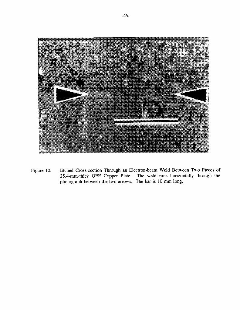
-46-
Figure 10: Etched Cross-section Through an Electron-beam Weld Between Two Pieces of 25.4-mm-thick OFE Copper Plate. The weld runs horizontally through the photograph between the two arrows. The bar is 10 mm long.

Exte
rnal
load
-47-
Time
Figure 11: Schematic Illustrating the Time Dependence of the Loading Conditions on aContainer in a Canadian Disposal Vault. Period A corresponds to the presaturation period during which the container is not subject to either hydrostatic or swelling pressures; vault saturation occurs during period B along with the development of the hydrostatic and swelling pressures; followed by a long-term stable period (period C) during which the external load on the container is constant.

-48-
Bulk WerIdyl), 0, NH, NO, Mf'
bacteria
UrmtnlOT aoohOsoigane acxls
\ (dostridia. propionbaoehum)otgane adds------------------“-butanol
acetone ahanol eopropand propone aod acetic add
CO, + H, ♦ HC00H
Metal
Figure 12: Schematic Cross-section Through a Hypothetical Biofilm on a Metal SurfaceIllustrating the Layered Structure of the Biofilm and Some of the Microbial Processes That Are Possible (Little et al. 1991).

-49-
1Non-Oxidizing
Figure 13: The Expected Evolution of Environmental Conditions Within the Disposal Vault.Vault conditions evolve from an initial warm, oxidizing period to an indefinite period of cool, non-oxidizing conditions.

Cra
ck v
eloc
ity (n
m/s
)
-50-
-0.7 -0.5 -0.3 -0.1 0.1 0.3 0.5
E(Vsce)
Figure 14: Evidence for a Threshold Potential for the Stress-corrosion Cracking of Copper.H O.l mol-dm ^ NaOAc pH 10.3 (Cassagne et al. 1990), ♦ 0.1 mol-dm"3 NaOAc pH 5.5 (Cassagne et al. 1990), * 1 mol-dm"3 NaNOz pH 9 (Cassagne et al. 1990), D 1 mol-dm"3 NaN02 pH 9 (Yu and Parkins 1987), 0 1 mol-dm"3 NaN02 pH 8
(Benjamin et al. 1988). The shaded region represents the range of potentials in which Sieradzki and Kim (1992) observed the TGSCC of Cu in non-tarnishing 15 mol-dm"3 NH4OH.

-51-
Figure 15:
-O- 1.8x1 (TVs
Potential Dependence of the Crack Velocity for the TGSCC of Copper in 1 mol-dm"3 NaNG2 at Two Strain Rates (Yu and Parkins 1987).

-52-
Figure 16: Three-dimensional Representation of the Susceptibility of OFHC and PDO Copperto Transgranular SCC in NaN02 Solutions as a Function of Potential (Benjamin et al. 1988). The data suggest a threshold [NaN02] and potential below which cracking does not occur.

-53-
APPENDIX A
STRESS CORROSION CRACKING OF COPPER
A.l REVIEW OF LITERATURE
The stress-corrosion cracking (SCC) of Cu has only been reported in three environments; ammonia, acetate and NO;. (Coppers are defined as those alloys designated UNS C10100 to Cl5760 containing a minimum of 99.3 wt.% Cu including Ag, and include oxygen-free, tough- pitch and phosphorus-deoxidized coppers.) The SCC of commercial and experimental alloys and of "pure" Cu (> 99.999 wt.% Cu) is considered in this section.
Pugh et al. (1966) were the first to report the SCC of pure Cu. Intergranular cracking (IGSCC) was reported in non-tarnishing ammonia solutions, consistent with the trend observed for a-brasses with Zn contents < 18 wt.% (Figure 3 of the main text). These results were disputed by Uhlig and Duquette (1969) who were unable to induce SCC in an ammonia solution that produced tarnishing of the surface, and who concluded that Pugh et al. (1966) had observed failure as a result of weakening by intergranular corrosion rather than by IGSCC. Subsequent work confirmed the original observations of Pugh et al., but the intergranular nature of the attack leaves doubt as to whether this can be classified as SCC of a "pure" metal or whether there is some influence of the segregation of impurities to the grain boundaries.
Small additions of various alloying elements have long been known to cause IGSCC of Cu alloys in tarnishing ammonia environments, dating back to the initial work of Thompson and Tracy (1949). These authors reported that additions of Zn, P, As, Sb, Si, Ni or Al over specific compositional ranges induce cracking of Cu in moist ammonia atmospheres. The susceptibility to cracking was correlated with the rate of intergranular corrosion of unstressed samples. Notably, tough -pitch, oxygen-free high-conductivity (OFHC, equivalent to oxygen-free electronic (OFE) UNS C10100) and a laboratory-prepared pure Cu were neither susceptible to SCC nor underwent intergranular corrosion. The addition of as little as 0.004 wt.% (40 ppm) P, however, lead to failure in constant load tests within the experimental time of 4 weeks (Figure 8 of main text). Practical cases of failure of IGSCC believed to be associated with the presence of ammonia have been reported for Cu-P alloys containing 0.033 wt.% P (Logan and Ugiansky 1965) and in Cu pipe in a urinal containing 0.07 wt.% P (Dempster 1966).
Dilute ammonia solutions (0.03-0.07 mol dm^ NH4OH) have been shown (Suzuki and Hisamatsu 1981) to cause transgranular SCC (TGSCC) of pure Cu under constant load by a tarnish-rupture mechanism (Chapter 2.2). These conditions result in a thick tarnish film, and cracking was clearly shown to propagate by rupture of the tarnish. Examination of the fracture surfaces showed that the tarnish formed a continuous layer on the fracture surface up to the crack tip. The crack path was transgranular for Cu and brasses containing < 1.3 wt.% Zn, but intergranular for higher Zn contents. The authors were able to obtain good agreement between observed and predicted crack growth rates, based on a tarnish-rupture model and experimentally determined

-54-
fracture strains for the Cu20 layer. For pure and tough-pitch Cu, the maximum crack growth rate at 70°C was -1.4 x 10"m m s"'. Cracking was only observed below a certain [NH4OH]; at higher [NH4OH] a loose, non-adherent oxide formed that could be easily removed from the surface and which would not sustain SCC. Cracking was only observed when an adherent Cu20 film was formed. The activation energy for crack growth (calculated from the time-to-failure assuming zero initiation time) was 15 kJ mol ' for pure Cu, suggesting that diffusion through solution was the rate-controlling step. Tarnish formation was found to follow a parabolic growth law, with an activation energy of 14 kJ-mol"1, leading the authors to conclude that the rate of cracking is controlled by the rate of tarnish growth. The nature of the rate-controlling diffusing species was not discussed.
A specific form of TGSCC of Cu in non-tarnishing ammonia solution has been reported by Sieradzki and Kim (1992) under conditions where the metal is undergoing anodic dissolution without film formation. Cracking was only observed over a range of strain rates and dissolution rates at which a microscopic porous structure formed. Initiation of a brittle crack in this porous layer lead to cracking by a film-induced cleavage mechanism (Chapter 2.3). The effect of dynamic straining was to cause etch pits to nucleate at approximately the same time, so that pits of similar size grew creating a uniform porous surface layer. If the strain rate was too slow (< 1 x 10"5 s '), the pits grew laterally and initiated at different times, resulting in a non-uniform porous layer that was unable to initiate a brittle crack. Alternatively, if the strain rate was too high (> 1.4 x 10"4 s '), ductile failure was observed. Similarly, cracking was only observed over a specific range of dissolution rates. If the dissolution rate was too high (> -500 pA-cm'2, equivalent to a corrosion rate of 12 mm a') or too low (<15 pA-cm"2, equivalent to 350 pm a"') the required microporous layer was not formed and no cracking occurred. Thus, this is a very specific case of SCC requiring a suitable combination of environment, dissolution rate and rate of dynamic straining.
Escalante and Kruger (1971) observed IGSCC of 99.9 and 99.999 wt.% Cu under constant load in cupric acetate, but not in cupric sulphate, solutions. In addition, illumination was found to suppress the IGSCC in acetate solutions. The rationale for studying these two solutions was that they exhibited similar tarnish growth rates to a-brass in tarnishing ammonia solutions. Cracking was observed to be limited to Cu20 formed preferentially at the grain boundary. Although, the authors suggest a tarnish-rupture model (Chapter 2.2), the comment that "When stress is applied, very small areas of metallic copper are exposed by rupture of the Cu20 film at the grain boundary...." indicates that a film-rupture/dissolution mechanism (Chapter 2.1) might be more appropriate. Escalante and Kruger explained the absence of cracking in sulphate solution by suggesting that local acidification prevented oxide growth, whereas acetate solutions buffered the pH in a region suitable for tarnish formation. Similarly, the effect of illumination, which suppresses film growth, was also explained in terms of its affect on the tarnishing process.
More recently, Cassagne et al. (1990) reported the TGSCC of Cu single crystals in 0.1 mol-dm2
sodium acetate and NaNOz as a function of applied potential. Susceptibility to cracking increased with decreasing strain rate but increasing potential. Cracking was only observed when an oxide (presumably Cu20) was present on the surface; thus no cracking was found in pH 3 solution, in

-55-
which voltammetry and ellipsometry showed that no oxide formed, but cracking was found in pH 5.5 and pH 9 solutions, in which oxide formation was observed. The precise properties of the oxide film that were responsible for cracking were not identified; for instance, film thickness was not a sufficient criterion for cracking since the crack growth rate in N02 solution was an order of magnitude higher than in acetate solution, despite a similar film growth rate in the two solutions. The film inducing SCC is likely to be a thin (10-40 nm thick) Cu20 layer that forms at the Cu/film interface, rather than the thicker Cu20 non-protective layer that forms when the inner layer breaks down. Because of the similarities of the fracture behaviour in acetate and N02
solutions and the cleavage-like appearance of the fracture surfaces, the authors suggested a film- induced cleavage mechanism was operative.
Many other studies have been performed in N02 solutions since the first report of TGSCC of Cu by Pednekar et al. (1979). In this initial study, pure Cu was observed to undergo TGSCC during slow strain rate tests (SSRT) in 1 mol-dm"3 NaN02. A slip-dissolution model was suggested, in which deformation at slip steps causes rupture of a Cu20 film resulting in crack advance by anodic dissolution at the exposed bare metal. Subsequently, Sieradzki et al. (1984) suggested a film-induced cleavage model to explain the TGSCC failure of pure Cu single crystals in aerated 1 mol-dm"3 NaNOz at a potential of 0 VSCE. The evidence for a film-induced cleavage model included the cleavage-like appearance of the fracture surfaces, the presence of crack-arrest markings and the correlation of acoustic emission and electrochemical transients. Cracking halted after 10-20 pm under constant displacement (approximating to constant load) conditions, when the dynamic straining was halted. Dynamic strain was considered to be necessary either to rupture the steps between the cleavage facets (for Cu, these steps were more ductile than the equivalent crystallographic steps observed for a-brass) or to cause rupture of the Cu2G film believed to be responsible for initiating the cleavage event.
Aaltonen et al. (1984) used the SSRT technique to study the SCC of OFHC Cu in 0.3 mol-dm3
NaN02 at 80°C. Transgranular cracking was observed at both the corrosion potential (ECORR) in aerated solution (-0.05 VSCE) and at +0.10 VSCE, following "intergranular initiation", presumably at grain boundaries. Fracture surfaces were cleavage like, and display what appear to be crack- arrest markings.
In a series of papers, Parkins and co-workers (Yu et al. 1987; Yu and Parkins 1987; Benjamin et al. 1988; Wu et al. 1991) have compared the observed cracking behaviour of Cu and a-brass in NaNG2 solutions to predictions based on dissolution and film-induced cleavage mechanisms. Crack initiation in both materials was found to occur at grain and twin boundaries, and not at slip planes in the body of the grains. (Cracking via a film-rupture/dissolution model, where rupture of the film occurs at slip steps might be expected to initiate at slip planes in the grains rather than at grain boundaries). Instead, crack initiation was believed to be caused by a difference in the mechanical properties of the film at grain boundaries (possibly enhanced by chemical heterogeneity at the grain boundary). Interestingly, although cracks initiated intergranularly, they propagated in a transgranular manner.
Yu and Parkins (1987) were unable to distinguish between film-rupture/dissolution and film-

-56-
induced cleavage models on the basis of crack-growth rates. Figures A.l and A.2 show their data relating the susceptibility of polycrystalline Cu (in terms of a crack-growth rate or the % reduction in area of tensile specimens) to the [NO;] and potential, respectively. These data suggest both threshold [NO;] and potentials below which cracking does not propagate. The behaviour of Cu-30Zn, which was more susceptible than Cu, is also shown on these figures, for comparison. Cracking was entirely transgranular for Cu, but was found to change from TG to IGSCC for brass. Yu and Parkins also measured the temperature dependence of (i) the crack velocity, (ii) the maximum current observed during rapid straining experiments and (iii) the rate of film growth. Both the crack velocity and dissolution rate were found to have activation energies of -21 kJ mol', compared with -51 kJ mol"1 for film growth. Fracture surfaces exhibited crystallographic features and crack-arrest markings, 2-4 pm apart.
Some of these observations support a dissolution-based model, whilst others favour film-induced cleavage. The identical activation energies for crack growth and dissolution clearly shows that dissolution plays a major rdle and tends to favour a dissolution-based model. On the other hand, the crystallographic character of the fracture surfaces and the presence of crack-arrest markings support the discontinuous cleavage model. Both models were found to give agreement between observed and predicted crack velocities under certain conditions, but not under others (Yu and Parkins 1987). Consequently, no firm conclusion was reached regarding the most appropriate mechanism. In a later paper (Wu et al. 1991), no effect of the frequency of cyclic loading was found on the crack-growth rate for a-brass in NaN02 solutions, as would be predicted by the film-induced cleavage model. Thus, although not explicitly stated, Parkins seems to favour a model based on a dissolution process. However, some of this evidence has been criticized by Cole et al. (1988). In particular, these authors suggest that dissolution rates measured by the rapid straining technique overestimate the actual current density at a film-free crack tip. Measurements made on scratched electrodes give current densities up to two orders of magnitude lower. As a consequence, crack velocities for a dissolution-controlled mechanism do not agree with observed rates for a-brass in NO; solutions, whereas agreement is much better for the film- induced cleavage model (Cole et al. 1988).
Benjamin et al. (1988) studied the TGSCC of two commercial Cu alloys in NO; solutions. No difference was found between the behaviour of OFHC and phosphorus-deoxidized (PDO) Cu. Figure 16 (main text) summarizes the susceptibility of both alloys to cracking (represented as the % reduction in area of tensile specimens in SSRT) as a function of E and [NO;]. As in previous work (Yu and Parkins 1987), these data provide evidence for threshold E and [NO;] below which cracking does not occur, at least for the conditions employed in these experiments. Thus no cracking was observed at room temperature for E < -0.1 VSCE for [NO;] up to 1 moldm'3, or for [NO;] - 0.001 mol dm3 at potentials up to +0.1 VSCE. The susceptibility to cracking was lower at 80°C than at room temperature, and was lower in deaerated, as opposed to aerated, solutions, even at identical applied potentials. In this and previous studies (Yu and Parkins 1987), the crack-growth rate was found to be a linear function of the strain rate, decreasing with decreasing strain rate. Crack-arrest markings and river patterns were again observed on fracture surfaces, consistent with a cleavage model. The authors suggested that the minimum potential for cracking was correlated with a critical dissolution current density of 0.1 mA-cm"2, as measured from rapid

-57-
(1 V min ') voltammetric experiments. Despite an apparent inclination towards a dissolution- based model, the authors were unable to demonstrate agreement between observed crack velocities and those predicted from such a model.
Uchida et al. (1991) have found that the susceptibility of pure Cu to TGSCC reaches a maximum at 1 mol-dm3 N02. The yield strength, tensile strength and % elongation at fracture of polycrystalline and single-crystal Cu in SSRT were found to be a minimum in 1 mol dm3 NQ2. Cracking was limited to the potential range 0 to +0.10 VSCE, corresponding to potentials at which a CuzO film was formed. From these observations, the authors suggested a dissolution-based model to explain the TGSCC of Cu, but did not exclude a mechanism based on rupture of the Cu20 tarnish layer. Mimaki et al. (1990) used biciystals of different orientations in SSRT in 1 mol-dm"3 NaN02. Initiation of cracking was found to occur within the grains for certain orientations, and at grain boundaries for others.
Beavers and Durr (1992) have studied the SCC of cold-worked oxygen-free Cu (UNS Cl0200) in NaN02 solutions using the SSRT. TGSCC was observed at EC0RR (-0.02 to +0.04 VSCE) in aerated 0.005 mol-dm"3 and 1 mol-dm3 N02 at 23°C, but not at 90°C. Cracking could be induced at both temperatures by anodic polarization (in the range +0.06 to +0.25 VSCE), with the crack velocity increasing with E. No fracture surfaces were shown or mechanisms discussed.
The various observations of SCC of Cu and the proposed mechanisms are summarized in Table 1 of the main text. The implications of these studies for the SCC of Cu containers in a Canadian disposal vault are discussed in Chapter 3 of the main text.
A.2 SCC STUDIES SPECIFICALLY RELATED TO NUCLEAR WASTE CONTAINERS
The SCC behaviour of Cu alloys has been studied in various natural and simulated groundwater solutions. Aaltonen et al. (1984) used artificial (Allard) and natural (Olkiluoto) Finnish groundwaters (Table A.l) in a study with OFHC Cu at 80°C. No cracking was observed at the single strain rate used (4.5 x 10'7 s ') in either solution at ECORR (ca. -0.05 VSCe) or when the specimen was prepolarized at +0.10 VSCE for 3 h at the start of the experiment to induce pitting of the surface. (Pits may act as crack initiation sites due to locally elevated stresses). The material was also immune to SCC when the [Cl ] and/or [SO4] were increased in the artificial groundwater by a factor of 100 (to 0.2 mol-dm3 and 0.01 mol-dm3, respectively) in both EC0RR and pre-pitted experiments.
Benjamin et al. (1988) also failed to observe SCC of OFHC or PDO Cu in an artificial Swedish groundwater (Table A.l) during SSRT at room temperature and at 80°C. These authors investigated a wider range of potentials (-0.10 to +0.30 VSCE) than Aaltonen et al. (1984) and used three strain rates between 1.8 x 10'6 and 1.7 x 10⁷ s '. SCC was also not observed over this range of potentials in groundwater containing the following additions: 0.03 mol-dm3 Cl", 0.001 mol-dm3 SO4, 0.017 mol-dm"3 COf/HCOj or 0.001 mol-dm3 N02.

-58-
Under simulated Canadian disposal conditions, King and Ryan (unpublished data) have not observed SCC on U-bend samples of OFE Cu exposed to irradiated saline groundwaters (SCSSS, Table A.l) or moist atmospheres and compacted buffer material saturated with SCSSS, for periods of up to 5 a. The presence of radiation (dose rate ~5 Gyh"1 or 500 rad-h"1) in these experiments is significant, because it allows for the possible formation of aggressive species (NH3 or NO;) by the radiolysis of moist air. The fact that no SCC was observed during the relatively long exposure period suggests that either aggressive species are not formed or that they are formed in insufficient quantities to induce SCC.
Several studies have been performed in J-13 water (Table A.l), or variants of J-13, the reference groundwater for the candidate U.S. repository at Yucca Mountain, Nevada. Yunker (1990) studied the SCC behaviour of three Cu alloys (oxygen-free, UNS C10100 and Cl0200; Cu-30Ni, UNS C71500; and Cu-7Al-3Fe, UNS C61300) in irradiated moist air at 95°C and 150°C and aqueous J-13 water at 95°C. The specimens were in the form of welded tear-drop samples and were exposed to radiation fields of 19 to 490 Gy h"1 (1.9 x 10³ to 4.9 x 10s rad-h"1) for periods of 13 to 16 months. No cracking of any of the specimens in any of the environments was reported. The fact that irradiation at such high dose rates (~2 to 45 times higher than the maximum dose rate for a Cu container) did not result in SCC is strong evidence that the irradiation of moist air will not produce SCC-inducing agents.
As part of their study on the effects of NO; on the SCC of UNS Cl0200, Beavers and Durr (1992) also studied the effect of J-13 water. No SCC of U-bend samples was observed at 90°C in J-13 water, in the vapour phase above J-13 water or in boil-down tests with J-13, over a period of up to 560 d. Cracking was not observed in so-called Solution No. 7 (Table A.l) either, an artificial solution designed to simulate the effects of concentration on the container surface ([Cl ] - 0.028 mol-dm"3, compared with 0.0002 mol-dm 3 in J-13) and the possible formation of organic acids due to the radiolysis of C02-containing environments (1.9 x 10³ mol-dm"3 oxalic acid). U-bend samples were exposed to the vapour phase and immersed in Solution No. 7 for periods up to 2014 h. Finally, Beavers and Durr (1992) considered the effects of NO; additions to J-13 as part of their study of NO;-induced TGSCC, described in Chapter A.l. Consistent with their findings in NO; solution alone, no SCC was observed at 90°C in J-13 water upon the addition of 0.005 mol-dm 3 or 1 mol-dm"3 NO; under freely corroding conditions in aerated solution. The effect of applied anodic potential was not studied. However, although cracking was observed at EC0RR in 0.005 mol-dm"3 NO; at 23°C, Cu was immune under these conditions when J-13 water was added. The authors explained this in terms of some unknown inhibitive agent present in J-13 water. Of the various constituents of J-13 water, the most obvious species that might cause passivation, and the species that is most prevalent, is HCO;. Carbonate and bicarbonate are known to induce passivation of Cu in electrochemical experiments (Sridhar and Cragnolino 1993), and could prevent SCC if it involved a dissolution process.
Maiya et al. (1990) also studied the SCC susceptibility of PDO Cu (UNS Cl2200), Cu-30Ni (UNS C71500) and Cu-7A1 (UNS C61400) in J-13 water at 93°C using the SSRT. These workers incorporated two drilled holes in the gauge length of the tensile specimen that could be fitted with pins to determine the effect of crevice corrosion on crack initiation. The specimens

-59-
were strained to -4% elongation (they were not strained to failure) and the gauge length sectioned and examined for evidence of cracking using SEM and metallographic techniques. Small cracks (10-20 pm in length) were observed during SEM examination for all three Cu alloys. The susceptibility of the alloys to SCC was expressed as the ratio of the stress at a given strain in the environment to the corresponding stress in air (an equivalent strain ratio at a given stress was also determined). Despite the observation of cracking, the stress and strain ratios, which were said to be sensitive indicators of SCC, were > 1 for Cu and Cu-7A1, i.e., the samples were less susceptible in the environment than in air. These latter results contradict the claim that short cracks were observed in these alloys.
REFERENCES
Aaltonen, P., H. Hanninen and M. Kemppainen. 1984. Stress corrosion testing of pure OFHC- copper in simulated groundwater conditions. Nuclear Waste Commission of Finnish Power Companies Report, YJT-84-21.
Beavers, J.A. and C.L. Durr. 1992. Stress-corrosion cracking studies on candidate container alloys for the tuff repository. U.S. Nuclear Regulatory Commission Report, NUREG/CR-5710.
Benjamin, L.A., D. Hardie and R.N. Parkins. 1988. Stress corrosion resistance of pure coppers in ground waters and sodium nitrite solutions. Br. Corros. J. 23, 89-95.
Cassagne, T.B., J. Kruger and E.N. Pugh. 1990. Role of the oxide film in the transgranular stress corrosion cracking of copper. Jn Environmentally Assisted Cracking, W.B. Lisagor, T.W. Crooker and B.N. Leis (eds.), ASTM STP 1049, American Society for Testing and Materials, Philadelphia, PA, 59-75.
Cole, A.T., R.C. Newman and K. Sieradzki. 1988. A comparison and evaluation of 'bare surface' electrochemical techniques for the investigation of stress corrosion cracking in alpha brass. Corros. Sci. 28, 109-118.
Dempster. N.S. 1966. Intercrystalline corrosion of phosphorus de-oxidized copper. Mater. Perform. 5, 27.
Escalante, E. and J. Kruger. 1971. Stress corrosion cracking of pure copper. J. Electrochem. Soc. 118, 1062-1066.
Logan, H.L. and G.M. Ugiansky. 1965. Two cases of stress corrosion cracking in copper tubing. Mater. Prot. 4, 79-80.
Maiya, P.S., W.J. Shack and T.F. Kassner. 1990. Stress corrosion cracking of candidate material for nuclear waste containers. Corrosion 46, 954-963.

-60-
Mimaki, T., Y. Nakazawa, S. Hashimoto and S. Miura. 1990. Stress corrosion cracking of copper bicrystals with (l 10)-tilt X3, £9, and Ell coincident site lattice boundaries. Metall. Trans. 21 A, 2355-2361.
Pednekar, S.P., A.K. Agrawal, H E. Chaung and R.W. Staehle. 1979. Transgranular cracking of copper in 1M NaN02 solution. J. Electrochem. Soc. 126, 701-702.
Pugh, E.N., W.G. Montague and A R C. Westwood. 1966. Stress-corrosion cracking of copper. Corros. Sci. 6, 345-346.
Sieradzki, K. and J.S. Kim. 1992. Etch pitting and stress-corrosion cracking of copper. Acta Metall. Mater. 40, 625-635.
Sieradzki, K., R.L. Sabatini and R.C. Newman. 1984. Stress-corrosion cracking of copper single crystals. Metall. Trans. 15A, 1941-1946.
Sridhar, N. and G.A. Cragnolino. 1993. Effects of environment on localized corrosion of copper-based, high-level waste container materials. Corrosion 49, 967-976.
Suzuki, Y. and Y. Hisamatsu. 1981. Stress corrosion cracking of pure copper in dilute ammoniacal solutions. Corros. Sci. 21, 353-368.
Thompson, D.H. and A.W. Tracy. 1949. Influence of composition on the stress-corrosion cracking of some copper-base alloys. Metall. Trans. 1949, 100-109.
Uchida, H., S. Inoue, M. Koyama, M. Morii and K. Koterazawa. 1991. Susceptibility to stress corrosion cracking of pure copper in NaN02 solutions. J. Soc. Mater. Sci. Jpn 40, 1073-1078.
Uhlig, H.H. and D.J. Duquette. 1969. Alleged stress-corrosion cracking of pure Cu. Corros. Sci. 9, 557-560.
Wu, D., H.S. Ahluwalia, H. Cai, J.T. Evans and R.N. Parkins. 1991. Cyclic loading effects in the environment sensitive cracking of a-brass. Corros. Sci. 32, 769-794.
Yu, J. and R.N. Parkins. 1987. Stress corrosion crack propagation in a-bra;s and copper exposed to sodium nitrite solutions. Corros. Sci. 27, 159-182.
Yu, J., R.N. Parkins, Y. Xu, G. Thompson and G.C. Wood. 1987. Stress corrosion crack initiation in a-brass exposed to sodium nitrite solutions. Corros. Sci. 27, 141-157.
Yunker, W.H. 1990. Corrosion behavior of copper-base materials in a gamma-irradiated environment. Westinghouse Hanford Company Report, WHC-EP-0188.

-61-
TABLE A.l
COMPOSITION OF VARIOUS SYNTHETIC AND NATURAL GROUNDWATERS
Species Allard1
(pg-g'1)Olkiluoto1
(pg-g'1)Swedish1 2
(Pg-g'1)SCSSS3
(pg-g"1)J-134
(Pg-g'1)Solution
No.75
(Pg-g‘)
Na+ 65 - 65 5050 44 bal
K+ 3.9 - 3.9 50 5.1 0.08
Ca2+ 18 68 18 15000 12.5 0.8
Mg2* 4.3 - 4.3 200 1.9 0.8
Sr2* - - - 20 - -
Fe2+ - - - - 0.006 -
Al3* - - - - 0.012 0.0004
Si02 12 - 12 15 58 215
Cl 70 20 70 34260 6.9 1000
<z> O 9.6 150 9.6 790 18.7 bal
HCOj 123 360 123 10 125 0.4
no3 - 1.4 - 50 9.6 0.2
no2 - <0.01 - - - -
PO3 - - - - 0.12 2.0
F - 0.6 - - 2.2 0.04
oxalic acid - - - - - 172
PH 8.2 8.1 8-8.2 7.0 7.6 5.0
TDS6 306 600 306 55445 284 -
1 Allard and Olkiluoto are artificial and natural Finnish groundwaters used by Aaltonen et al. (1984).2 Swedish is a synthetic Swedish groundwater used by Benjamin et al. (1988).3 SCSSS is a synthetic Canadian Shield saline solution commonly used in studies in the Canadian program.4 J-13 is the reference groundwater for the U.S. repository site at Yucca Mountain, NV.5 Solution No. 7 is a synthetic variant of J-13 designed to simulate the effect of radiolytically altered groundwater.6 Total dissolved solids.

Cra
ck v
eloc
ity (1
0*6
mm
/s)
-62-
Brass
Copper
log ([NaN02]/mol®dm'3)
Figure A.l: Variation of the Crack Velocity with [NaN02] for Copper and Brass (Yu and Parkins 1987). The data suggest a threshold [NaN02] below which cracking does not occur.
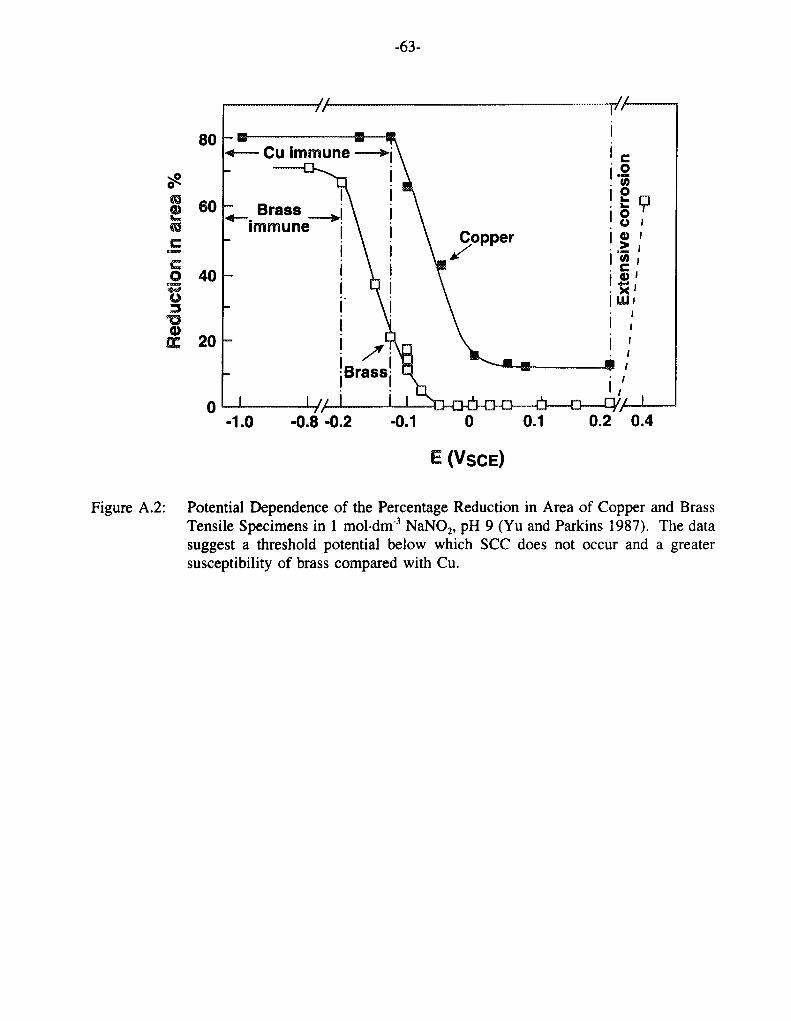
-63-
Cu immune
Brassimmune
Copper
Brass
0.2 0.4-0.8 -0.2
E (VsCE)
Figure A.2: Potential Dependence of the Percentage Reduction in Area of Copper and Brass Tensile Specimens in 1 moldm3 NaN02, pH 9 (Yu and Parkins 1987). The data suggest a threshold potential below which SCC does not occur and a greater susceptibility of brass compared with Cu.

-64-
APPENDIX B
STRESS CORROSION CRACKING OF a-BRASS IN AMMONIA SOLUTIONS
B.l GENERAL CONSIDERATIONS
The SCC behaviour of a-brass in ammonia solutions has been studied extensively and reviewed in some detail by Pugh and coworkers (Pugh et al. 1969; Pugh 1971, 1979; Bertocci et al. 1990). Figure 3 (of the main text) shows the effect of Zn content on the time-to-failure of various a-brasses in both tarnishing and non-tarnishing solutions (Pugh 1971). (Experimental times-to- failure include both the initiation and crack propagation periods, which are rarely separated. Therefore, although time-to-failure is a useful measure of the susceptibility of a material, it is only related to the mean crack-growth rate if the initiation time is zero). Cracking can be either intergranular (IGSCC) or transgranular (TGSCC); IGSCC occurring in tarnishing solutions and either TGSCC or IGSCC occurring in non-tarnishing solution, depending upon the Zn content of the alloy. (The difference between tarnishing and non-tarnishing solutions will be explained below). The dependence of the time-to-failure on the Zn content is somewhat greater in tarnishing solutions; in which (at least for Zn contents >10 wt.%) the crack-growth rate is higher than in non-tarnishing solutions. In non-tarnishing solutions, a transition from TGSCC to IGSCC is observed at a Zn content of 18 wt.%. In tarnishing solutions, cold working the material leads to a change from IGSCC to TGSCC in Cu-30Zn (Pugh 1979).
The dependence of the SCC behaviour of Cu-30Zn on the dissolved [Cu] (in the form of Cu(NH3)4+ and Cu(NH3)j+ complexes) is shown in Figure 4 (main text). At a critical [Cu(II)] (corresponding to -0.009 moldm"3 in 1 mol dm'3 NH4OH, Pugh 1971), a visible black tarnish forms on the Cu surface, the formation of which corresponds to (a) a positive shift in the open- circuit potential, (b) a decrease in the uniform dissolution rate and (c) a change from TGSCC to IGSCC.
The influence of the tarnish film on the crack path was first reported by Mattsson (1961). By adjusting the pH of a solution containing 0.05 mol dm3 Cu(II) and 1 mol dm3 NH4OH, Mattsson observed either no cracking, IGSCC or TGSCC (Figure B.l). IGSCC was only observed when a well-defined tarnish film formed on the samples in the pH range 6.3 to 7.3. At higher or lower pH, TGSCC was associated with the formation of a thin non-tarnish film. By comparison with the E/pH diagram for Cu, Mattsson related the instances of IGSCC to the presence of Cu20, and, in particular, the coexistence of both Cu20 and Cu(NH3)2 (Hoar and Rothwell 1970). In addition to indicating the importance of the surface film on the SCC of Cu, the close comparison between the observed behaviour and the predictions based on thermodynamic considerations indicates that the system is near equilibrium and that the interfacial kinetics are fast.
Many of the experimental studies have focussed on the SCC of Cu-30Zn because it demonstrates the change in crack orientation in tarnishing and non-tarnishing solutions. Studies on this material (Pugh et al. 1969) have shown a different temperature dependence for crack growth via

-65-
the two pathways, suggesting a difference in the respective mechanisms. Over the temperature range -25°C to 50°C, the activation energy for IGSCC in tarnishing solutions is ~41 kJ-mol"1, compared with ~68 kJ mol ' for TGSCC in non-tarnishing ammonia. It is significant, however, that both of these values are higher than the value of 10-20 kJ-mol'1 that would be expected for a solution diffusion-limited process, despite the fact that, as shown below, both anodic and cathodic reactions on the external surface of the material are believed to be under transport control because of the fast interfacial kinetics. The discrepancy between the observed activation energies and that expected for diffusion in solution suggests that the rate of cracking is not controlled by the rate of the electrochemical processes occurring outside the crack.
Other studies on Cu-30Zn have shown no apparent threshold stress for IGSCC or TGSCC (Pugh et al. 1969). Plots of the time-to-failure against engineering stress exhibit a bimodal behaviour, being less stress-dependent at higher stresses (Pugh et al. 1969). However, these results do not take into account the reduction in cross-sectional surface area of the sample at higher strains, making it difficult to be certain that the observed bimodal behaviour is real. Other studies have shown a direct relationship between the crack-growth rate and the stress intensity at the crack tip in tarnishing Mattsson's solution at pH 7.2 (McEvily and Bond 1965).
Figure 9 (main text) shows the relationship between the time-to-failure and the grain size for the IGSCC of Cu-30Zn in tarnishing moist ammonia vapour (Pugh et al. 1969). It is likely that this dependence reflects an effect of the grain size on the crack propagation, rather than crack initiation, because crack initiation at grain boundaries would favour an increase in failure time with increasing grain size.
The electrochemical reactions occurring during the SCC of Cu alloys in ammonia, both on the exposed surface and within cracks, have been studied in some detail. Ammonia forms a number of complexes with both Cu(I) and Cu(II) (Sill6n and Martell 1964). Various [NH4OH] have been used in experimental studies, usually between 1 and 15 mol dm"3. The use of such concentrated solutions stems from the realization that high concentrations of NH4OH are present during the most important practical case of SCC, the so-called season cracking of brass in moist ammonia atmospheres, in which the surface is covered by a thin liquid layer (Bertocci et al. 1990). The [NH4OH] determines the concentrations of dissolved Cu(I) and Cu(II) species in solution, which are generally assumed to be in equilibrium with NH3 because of fast complexation kinetics. For [NH4OH] > 1 mol dm3, Cu(NH3)2 is the predominant cuprous species and Cu(NH3)4+ and Cu(NH3);+ the prevalent cupric complexes, with the pentaammonia species favoured at the higher [NH4OH]. Because the complexant is NH3, the speciation is also affected by the pH, through the equilibrium
NH3 + H+ * NH; (B.l)
The concentrations of uncomplexed Cu+ and Cu2+ are small (Bertocci et al. 1990).
Copper dissolves anodically as Cu(I) in ammonia solutions, stabilized as the cuprous-ammonia complex ion Cu(NH3)2. In 02-containing environments, however, homogeneous oxidation of

-66-
Cu(I) to Cu(II) occurs. In the presence of bare Cu metal, Cu+ and Cu2+ are also connected via the disproportionation reaction
Cu2+ + Cu * 2Cu+ (B.2)
The major cathodic reactant in ammonia solutions is Cu(II), even in the presence of Oz. Initially, in Cu-ffee aerated solution, the interfacial reduction of Oz is coupled to Cu dissolution. The reduction of Cu(II) quickly becomes the predominant cathodic reaction, however, as the dissolved [Cu(II)j increases as a result of Cu dissolution and homogeneous oxidation of Cu(I) by 02. This leads to an autocatalytic reaction, since the interfacial reduction of Cu(II) produces two Cu(I) species (Reaction (B.2)), which are then oxidized to two Cu(II) species by reaction with 02
(Figure B.2). Of importance here, is the fact that the oxidant concentration can be many times that of dissolved 02, which is limited by its solubility. Therefore, the reduction kinetics of Cu(II) not only represent a faster cathodic process because the exchange current density for Cu(II) is greater than that for 02, but also because the oxidant is present at a higher concentration, especially in thin moisture films.
As a consequence of the fast anodic and cathodic interfacial kinetics, both reactions are transport limited on bare surfaces. The distribution of species within the diffusion layer and bulk solution is illustrated schematically in Figure B.3 (Bertocci et al. 1990). As noted above, the bulk concentration of Cu(II) is higher than that of 02, resulting in a higher flux of oxidant to the surface. There is virtually no dissolved 02 in the diffusion layer. Oxygen is limited to the outer region of the diffusion layer only, where it oxidizes Cu(I) to Cu(II). The approximate linear dependence of the dissolution rate on [Cu(II)] for non-tarnishing solutions (Figure 2(b), main text) is consistent with a transport-limited dissolution reaction.
As shown in Figure B.2, Zn can also dissolve in ammonia solutions, with the formation of Zn(NH3)4+ complexes. Because of the electrochemical activity of Zn compared to that of Cu, brass undergoes dezincification in ammonia solutions. Dezincification is thought to play a rdle in a number of SCC mechanisms, as described below. Dezincification alone, however, is not a sufficient cause for SCC, as brass undergoes more rapid dezincification in Cl solutions than in ammonia, yet Cl tends to inhibit SCC in brasses (Shahrabi and Newman 1989).
The chemical reactions occurring within the crack itself have been considered by Bertocci and Pugh (1987). Because of the limited rate of diffusion, the concentration of 02 in the crack is negligible. Consequently, any Cu(II) within the crack is rapidly reduced to Cu(I), but is not reformed by the homogeneous oxidation by 02. Bertocci and Pugh (1987) have modelled the crack chemistry and crack-tip potential for the TGSCC of a-brass in non-tarnishing ammonia. Because the crack walls were assumed to be oxide-free, thus permitting the cathodic reduction of Cu(I) within the crack, and because of the high electrical resistance in the crack, they assumed that crack growth was driven by electrochemical reactions occurring within the crack, and that the external surfaces were effectively decoupled from the process. A schematic polarization diagram for the possible reactions is shown in Figure B.4. Thus, on a freshly exposed surface, Zn dissolution at the crack tip can be supported by the deposition of Cu metal on the crack walls,

-67-
at a potential Eye,. As dezincification proceeds, however, a Cu-rich surface layer is formed and the rate of Zn dissolution becomes limited by solid-state diffusion. As it does so, the potential increases until it is governed by the Cu/Cu(I) equilibrium potential on the dealloyed surface (Eqcz). Repeated crack propagation and dezincification processes will lead to a periodic variation of the potential within the crack between Eye, and Ey^.
(The question of how NH3 is transported into a stress-corrosion crack was not addressed by Bertocci and Pugh, even though the usual route for solute transport into a crack is via the migration of charged species. This is an important question in die mechanism of ammonia- induced SCC and one which has not been addressed in the literature. If there is no efficient mechanism for transporting uncharged NH3 into a crack, does NH3 take part in the crack-tip reactions?).
Above a critical [Cu(II)] (Figure 4, main text), a visible tarnish film forms on the surface (Figure 5, main text). The tarnish layer is depleted in Zn (compared with the underlying alloy), but may be non-stoichiometric, resulting in significant electrical conductivity (Pugh 1979). The layer has a characteristic black colour, which distinguishes it from the non-adherent brown film that often forms in non-tarnishing solution, which does not support SCC. The thick Cu20 layer can grow at both interfaces; at the solution/tarnish interface by the cathodic reduction of Cu(II) and the precipitation of Cu(I) and at the inner film/tamish interface by precipitation of Cu(I) dissolving through defects in the inner layer. The relatively high conductivity of the layer permits this physical separation of coupled anodic and cathodic processes to occur.
The [Cu(II)] at which the tarnish layer forms is a function of the solution pH and [NH4OH]. The concentration of Cu(I) species is controlled by the bulk [Cu(II)] either by the equilibrium with Cu metal (Reaction (B.2)) or through the rate of the interfacial reactions (Figure B.3). The [NH4OH] determines the concentration of free Cu+ and the pH determines the solubility of Cii+. Confusion has occasionally arisen in the literature over whether a given solution causes tarnishing or is non-tarnishing, despite having the same [Cu(II)]. This difference can usually be explained by the method of preparation: Cu(II)-ammonia solutions prepared from oxygenated ammonia containing Cu metal have a higher pH than those to which a soluble Cu(II) salt is added. In the CyCu metal systems, corrosion of the Cu by 02 and the subsequent homogenous oxidation reaction leads to sufficient OH" to cause tarnish formation at a [Cu(II)] lower than that found necessary using Cu(II) salts, simply because of the higher pH in the former solution (Bertocci et al. 1990).
Because of the observed change in SCC behaviour upon the formation of the tarnish (Figure 4, main text), it was long assumed that the tarnish played a significant rdle in IGSCC. Pinchback et al. (1975), however, showed that the tarnish layer is not present at the crack tip, but grows on the crack walls some distance behind the advancing crack. It is, in fact, the thinner inner Cu20 layer that is present at the crack tip, which is involved in the SCC mechanism.
Many of the processes described above are analogous to the reactions in Cl solutions, yet the available evidence suggests that Cl has an inhibitive effect on the SCC of brass. Under

-68-
atmospheric exposure conditions, brass is less susceptible to IGSCC in marine atmospheres compared with rural and urban environments (ASM Handbook 1987). Furthermore, brass is used extensively in seawater applications. The apparent beneficial effect of Cl" may be due to its effect on the tarnish film. The rate of tarnish growth is higher in ammonia solutions than in Cl" (Suzuki and Hisamatsu 1981; Deslouis et al. 1988; Sutter et al. 1995, Figure 7 in main text). In addition, it is possible that the formation of an electrically insulating CuC12-3Cu(OH)2 layer could inhibit tarnish growth in Cl" solution, whereas no equivalent basic cupric ammonia precipitate forms. These arguments, however, relate to the properties of the tarnish layer, which has been shown to form behind the advancing crack. Alternatively, the presence of Cl" might interfere with the formation of the epitaxial inner Cu20 layer, which is present at the crack tip, or cause it to be more or less protective than that formed in Cl -free environments.
King and Greidanus (1996) studied the effects of NH3 additions on the dissolution of Cu in deaerated 0.1 moldm"3 NaCl. The results of both potentiodynamic and steady-state potentiostatic experiments suggest that there is a competition between Cu dissolution as CuCl2 and as the equivalent ammonia complex Cu(NH3)2. Voltammetric experiments indicated that the addition of as little as I0"4 mol dm3 NH4OH inhibits Cu dissolution as CuCl2, but promotes the growth of a CuzO layer. With increasing NH4OH concentration (> 10"2 mol dm 3), however, Cu dissolves primarily as Cu(NH3)2 and Cu20 formation is suppressed (Figure B.5). The effect of NH3 on both the interfacial and solution complexation reactions was determined from the intercepts and slopes of Koutecky-Levich plots. The fact that the intercepts were non-zero indicates that the overall dissolution reaction is under joint kinetic-transport control. Figures B.6 and B.7 show the [NH4OH] dependence of the slopes and intercepts in 0.1 mol dm'3 NaCl (pH 7) for various potentials. The independence of both slopes and intercepts at [NH4OH] < 102 mol dm"3, especially at higher potentials, suggests that the dominant anodic reaction was the same as in NH4OH-free solution, namely
Cu + Cl" * CuClads + e" (B.3a)
CuClgd,. + Cl * CuCl2 (B.3b)
At higher [NH4OH], dissolution via the overall reaction
Cu + 2NH3 - Cu(NH3)2 + e (B.4)
becomes more important, and dominates at concentrations greater than -0.1 mol dm 3 at a potential of -0.20 VSCE, as indicated by the slope of -2 in Figure B.6. However, there is a gradual change in slope in these figures, rather than a sudden change in dependence, suggesting a gradual transition in the dominant surface reactions and major solution species. Note also, the insensitivity of the slopes and intercepts to [NH4OH] at higher potentials, indicating a potential dependence that is not yet fully understood. These results do indicate, however, that even small amounts of ammonia can influence the dissolution behaviour of Cu in Cl" solutions. Consequently, although a-brass and Cu are susceptible to SCC in ammonia solutions, the addition of Cl" will alter the mechanism of the interfacial reaction and, possibly, reduce their susceptibility

-69-
to cracking.
B.2 mCMANim QJEJNXERGRANULAR.SCC
The association of IGSCC with tarnishing solutions inevitably lead to the suggestion that some form of tarnish or film rupture was involved in the SCC mechanism (Pugh et al. 1969; Pugh 1971, 1979). Originally, cracking was believed to propagate due to the rupture of the tarnish film. In a tarnish-rupture mechanism, the crack is limited to the depth of the tarnish layer. Crack advance is a result of the fracture of the tarnish layer (Chapter 2.2). The intergranular nature of the attack was explained in terms of preferential film growth at more anodic sites at grain boundaries due to the segregation of alloying components. The intergranular path may be preferred either because the oxide is more easily ruptured at the grain boundary or because of the segregation of Zn to these locations and the subsequent effect on the repassivation kinetics (Pugh 1979). The effect of Zn alloying, which has a large effect on the crack-growth rate (Figure 3, main text), is thought to result from the effect of Zn on the repassivation kinetics (Pugh 1979), higher Zn contents presumably preventing repassivation at the crack tip. The observation by Pinchback et al. (1975) that the tarnish did not extend to the crack tip, however, led to the suggestion that IGSCC involves a film-rupture/anodic dissolution mechanism (Pugh 1979; Bertocci et al. 1990).
In the film-rupture/anodic dissolution model (Chapter 2.1), crack advance occurs by electrochemical dissolution of the metal following rupture of a protective film. Consistent with Pinchback's observation, the protective film is thought to be the underlying thin Cu20 layer at the crack tip, rather than the thicker porous Cu20 layer. Plastic deformation at the crack tip is supposed to lead to continuous rupture of the film, and the resultant fracture surfaces are smooth indicative of a dissolution process. Crack growth rates can be calculated from Faraday's law, with a rate of 2.5 x 10"4 cm s ' equivalent to a crack-tip current density of 3.4 A cm2 (Pugh 1979). Fracture surfaces are indeed found to be featureless (a previous observation of crack- arrest markings now being thought to result from the emergence of slip planes on the fracture surface following crack advance), and the absence of detectable acoustic emissions are both consistent with a continuous cracking process. More recently, however, Loto and Gottis (1987) found electrochemical transients during the IGSCC of Cu-30Zn, suggesting that under some circumstances periodic repassivation at the crack tip could occur resulting in non-continuous crack advance.
Although the film-rupture/dissolution mechanism is now well accepted for IGSCC of a-brass in tarnishing solutions (Pugh 1979; Bertocci et al. 1990), the literature is less clear on whether the same mechanism applies to non-tarnishing solutions. As shown in Figure 3 (main text) the crack path in non-tarnishing solutions changes from transgranular to intergranular at a Zn content of 18 wt.%. The question of whether this change in crack path involves a change in mechanism is usually conveniently avoided by only discussing the behaviour of Cu-30Zn, for which there is a clear distinction between the crack paths in the two solutions. For Cu-5Zn, however, cracking is intergranular in both tarnishing and non-tarnishing solutions, but it is not clear from

-70-
the literature whether the film-rupture/dissolution mechanism is applicable to both solutions. Added to this uncertainty is the observation that the crack path for Cu-30Zn in tarnishing solution, which would normally be intergranular, changes to transgranular upon cold working the material (Pugh 1979). A film-rupture mechanism cannot be ruled out in non-tarnishing solution, because the film being ruptured is the thin epitaxial Cu20 film (which is also present in non- tarnishing solution) and not the thick tarnish layer (which is not).
It appears that the original clear distinction between the behaviour of a-brass in tarnishing (IGSCC) and non-tarnishing (TGSCC) solutions is not so clear after all. It is now generally accepted that both IGSCC or TGSCC can occur in either solution, and that the orientation of the crack path is a better indication of the underlying mechanism than whether a tarnish film forms or not (Pugh 1979; Bertocci et al. 1990). In other words, the mechanism of IGSCC (film- rupture/anodic dissolution) is different from that of TGSCC (see below). It is possible that both mechanisms are operative in a given alloy in a given environment, and that the observed crack orientation depends on the dominant mechanism.
B.3 MECHANISM OF TRANSGRANULAR SCC
The TGSCC of Cu-30Zn in non-tarnishing ammonia solutions is thought to be caused by a film- induced cleavage mechanism (Sieradzki and Newman 1985). This is a fundamentally different mechanism from other SCC mechanisms in that the initiation of a crack in a thin surface layer can induce a brittle crack to propagate into the underlying metal, causing cleavage-like fracture in what would otherwise be a ductile material (Chapter 2.3). The ratio between the thickness of the initiating layer and the length of the cleavage crack is typically of the order of 1:100 for Cu alloys. There is now increasing evidence to support this mechanism, and it has been proposed to apply to many, if not all, instances of TGSCC (Sieradzki and Newman 1987).
The foundation of this mechanism is the appearance of the fracture surfaces and the discontinuous nature of the crack advance (Bertocci et al. 1990). Fracture surfaces appear to be cleaved in a brittle manner and exhibit flat primary facets in the {110} plane separated by steps. Opposite surfaces match perfectly. The crack radiates in a fan-like pattern from the site of initiation and crack-arrest markings can be observed, with a typical spacing of -1 pm for Cu-30Zn in ammonia solutions and an interval between crack events of ~10 s (Bertocci et al. 1990). The discontinuous nature of the cracking process has been confirmed by acoustic emission and electrochemical noise measurements which have been linked to the formation of the cleavage cracks (Newman and Sieradzki 1983; Sieradzki and Newman 1985), and by marking the position of the crack tip by periodic load pulses and observing the pattern of these marks on the fracture surface (Bertocci et al. 1990). The discontinuous nature of the crack advance is significant, because it eliminates any mechanism that would suggest continuous crack propagation.
Other important observations on the TGSCC of a-brass are that it can occur in the absence of Cu dissolution (Bertocci et al. 1984; Shahrabi et al. 1993) and that it does not require continuous

-71-
exposure to the corrosive environment (Newman et al. 1989). The fact that cracking is observed in solutions pre-equilibrated with Cu(I), i.e., in solutions in which no net dissolution of Cu takes place, rules out mechanisms based on the general dissolution of the material (i.e., film- rupture/dissolution), but it does not rule out an effect due to dealloying. The experiments carried out by Newman et al. (1989) under various environmental conditions provide strong support for the film-induced cleavage model. Brittle failure of the entire sample was observed after a superficial amount of corrosion if the specimen was quenched in liquid nitrogen, but not if the sample was allowed to age at room temperature prior to straining (only ductile failure was observed in control experiments at 77 K). This indicated that a thin corroded layer could initiate a crack that would propagate through the whole sample, but that the requisite properties of this layer were destroyed if it were allowed to age at room temperature. Furthermore, these observations are inconsistent with many other SCC mechanisms because of the absence of a liquid phase at 77 K (therefore, no dissolution can occur as required for film-rupture mechanisms; no adsorption takes place from solution as required by adsorption models) and because a crack in a thin surface layer lead to failure of the complete sample (inconsistent with a tarnish-rupture mechanism). These results also rule out any mechanism involving dealloying in which the crack advance is limited to the thickness of the dealloyed layer (Bertocci et al. 1990).
More supporting information for the film-induced cleavage model has come from the study of other face-centred cubic materials, such as Au-Cu, Au-Ag and Cu-Al alloys. These alloys are also found to undergo TGSCC leading to the formation of cleavage-like cracks along the {110} plane. Cracks have been observed in Cu-Au (Lichter et al. 1986) and Au-Ag (Kelly et al. 1991) alloys that initiate in thin dealloyed surface layers and then propagate for significant distances into the unaffected alloy.
In common with the behaviour in Au-Cu alloys, the thin surface layer in which the crack initiates in a-brass in ammonia is believed to be a dealloyed layer. However, not all dealloyed layers will induce cleavage. Dealloyed layers with small pores (~nm size) of a uniform size are suitable for initiating film-induced cleavage, whereas layers with large or irregularly sized pores are not. The most important properties of the layer are (Sieradzki and Newman 1987): the degree of mismatch in the lattice parameters of the film and substrate; the elastic modulus mismatch; the coherency of the film; the geometric shape of the film surrounding the crack; the porosity of the layer, and; the inherent brittleness of the film. For example, the effect of porosity of the dealloyed layer is believed to explain the absence of cracking observed by Newman et al. (1989) when the layer was allowed to age at room temperature. The susceptible microporous layer coarsens by surface diffusion of metal atoms, resulting in a macroporous layer of larger pore size that does not seem suitable for initiating SCC. Similar effects of coarsening of dealloyed layers by surface diffusion are observed in Cl solutions. The adsorption of Cl increases the surface mobility of Cu atoms, just as it does for Au (Kelly et al. 1993). Consequently, dealloyed layers formed in Cl" solutions are coarser than those formed in NH3 (adsorbed NH3 appears to inhibit surface diffusion), although as little as 10"3 mol dm 3 NH4OH in 0.6 mol dm3 Cl" solution is sufficient to suppress the effect of Cl" (Shahrabi and Newman 1989).
The effect of NH3 on the dealloying of a-brass in Cl" solutions is interesting because it suggests

-72-
that the importance of NH3 in inducing SCC is not concerned with its ability to complex Cu(I) in solution. Shahrabi and Newman (1989) found that NH3 affected dealloying at pH 5, at which there is no complexing capacity of NH3 (since it exists primarily as NHJ in solution at this pH). Therefore, they suggested that ammonia (or ammonium ions) inhibited macro-dealloying by adsorbing on the surface. A similar inhibiting effect on dealloying is obtained if As is added to the alloy. The effect of NH3 in preventing the development of macroporous dealloyed layers on brass in Cl" solutions can be seen in terms of the competitive adsorption of NH3 and Cl". Newman (1992) has suggested that for SCC induced by micro-dealloyed layers:
1. "Macro-de-alloying requires adequately rapid surface diffusion of the more noble alloy component(s), to reduce the pore electrolyte resistance. This diffusion occurs particularly rapidly in chloride solutions, owing to the enhancement of Ds by Cl adsorption, but is generally enhanced by any simple anionic specific adsorption.
2. Macro-de-alloying is not favourable for SCC unless it is so rapid that an adequate region with nanometre porosity exists at the de-alloying front.
3. Micro-de-alloying, provided it can proceed to sufficient depth (tens of nm) without coarsening of the nanometre porosity, is a powerful way of activating SCC.
4. There is a distinction between micro-de-alloying, which propagates slowly above Ec because the pore size is pinned at an extremely small value, and subcritical de-alloying below Ec, which propagates slowly because the noble alloy component forms a relatively continuous layer that blocks the dissolution process.1
5. Adsorption of (group) VB elements in cationic or relatively uncharged form promotes micro-de-alloying by lowering Ds. The source can be the alloy (As in brass; P or N in austenitic stainless steel) or the solution (NH3, possibly Cu(NH3)z, on brass; pyridine on gold). Generally the alloy is a more effective source, as adsorption of a solution species in the pores of a de-alloyed layer can lead to its depletion at the de-alloying front.
6. Adsorption of group VB elements can completely counteract the effect of Cl on Ds, both in brass and austenitic SS."
The importance of these observations is that they help explain the general absence of SCC in Cl - containing environments and allow the prediction of the range of environments and alloys in which SCC will be observed. Thus, admiralty brass (which contains 0.04 wt.% As) is susceptible to TGSCC in a wider range of environments than non-arsenical brass. If correct, these "rules" would also suggest that the N and P contents of brass alloys should be minimized to reduce the susceptibility to SCC, as should exposure to environments containing these elements.
1 Ec is a critical potential below which only superficial dealloying can occur (Newman 1992).

-73-
The dependence of the crack path on Zn content in non-tarnishing solutions can be explained in terms of the formation of the dealloyed layer. The transition from TGSCC to IGSCC at a Zn content of -18 wt.% corresponds to the threshold value below which dealloying does not occur (Sieradzki et al. 1987). Exactly the same behaviour is observed for Cu-Al alloys; the threshold limit for dealloying is 11-16 atom%, which corresponds to the limit for SCC. This observation would suggest that both IGSCC (probably via a film-rupture/dissolution mechanism) and TGSCC (via film-induced cleavage) are both operative in non-tarnishing environments; IGSCC being observed under conditions in which TGSCC does not initiate.
Whether both mechanisms are also operative in tarnishing solution is uncertain. If they are, it would appear that IGSCC is favoured, possibly because the crack growth rates for a dissolution- controlled process exceed the mean rate for TGSCC (Figure 3 in main text). Why cold working the alloy would induce TGSCC is unclear, although Pugh (1979) has suggested that both the effect of cold work on the crack path in tarnishing solution and the change in crack path at -18 wt.% Zn in non-tarnishing solution are connected with the dislocation structure of the material; planar dislocation arrays being favoured at Zn contents > 18 wt.% or by cold work, and cellular dislocations at lower Zn contents or in annealed alloys.
REFERENCES
ASM Handbook. 1987. Corrosion of copper and copper alloys. In Metals Handbook, Ninth Edition, Volume 13. Corrosion. American Society for Metals International, Metals Park, OH, 610-640.
Bertocci, U. and E.N. Pugh. 1987. Modelling of the potential at the tip of a transgranular stress- corrosion crack in the alpha-brass-ammonia system. In Corrosion Chemistry Within Pits, Crevices and Cracks, A. Turnbull (ed.), Her Majesty's Stationery Office, London, U.K., 187-201.
Bertocci, U., F.I. Thomas and E.N. Pugh. 1984. Stress corrosion cracking of brass in aqueous ammonia in the absence of detectable anodic dissolution. Corrosion 40, 439-440.
Bertocci, U., E.N. Pugh and R E. Ricker. 1990. Environment-induced cracking of copper alloys. %n Environment-induced Cracking of Metals, R.P. Gangloff and M.B. Ives (eds.), NACE International, Houston, TX, 273-285.
Cragnolino G. and N. Sridhar. 1992. A review of stress corrosion cracking of high-level nuclear waste container materials - 1. Center for Nuclear Waste Regulatory Analyses Report, CNWRA 92-021.
Deslouis, C., B. Tribollet, G. Mengoli and M.M. Musiani. 1988. Electrochemical behaviour of copper in neutral aerated chloride solution. I. Steady-state investigation. J. Appl. Electrochem. 18, 374-383.

-74-
Galvele, J.R. 1987. A stress corrosion cracking mechanism based on surface mobility. Corros. Sci. 27, 1-33.
Hoar, T.P. and G.P. Rothwell. 1970. The potential/pH diagram for a copper-water-ammonia system: its significance in the stress-corrosion cracking of brass in ammoniacal solutions. Electrochim. Acta 15, 1037-1045.
Kelly, R.G., A.J. Frost, T. Shahrabi and R.C. Newman. 1991. Brittle fracture of an Au/Ag alloy induced by a surface film. Metall. Trans. 22A, 531-541.
Kelly, R.G., A.J. Young and R.C. Newman. 1993. The characterization of the coarsening of dealloyed layers by EIS and its correlation with stress-corrosion cracking. Jn Electrochemical Impedance: Analysis and Interpretation, ASTM STP 1188, J.R. Scully, D C. Silverman and M.W. Kendig (eds.), American Society for Testing and Materials, Philadelphia, PA, 94-112.
King, F. 1996. A model for the corrosion of copper containers in a Canadian nuclear fuel waste disposal vault. Part 1. The corrosion model. Atomic Energy of Canada Limited Report, AECL-11472, COG-95-520.
King, F. and G. Greidanus. 1996. The anodic dissolution of Cu in aqueous chloride/ammonia solutions. In preparation.
Lichter, B.D., T.B. Cassagne, W.F. Flanagan and E.N. Pugh. 1986. Metallographic studies of transgranular stress-corrosion cracking in copper-gold alloys. Microstruc. Sci. 13, 361-378.
Loto, C.A. and R.A. Cottis. 1987. Electrochemical noise generation during stress corrosion cracking of alpha-brass. Corrosion 43, 499-504.
Mattsson, E. 1961. Stress corrosion in brass considered against the background of potential/pH diagrams. Electrochim. Acta 3, 279-291.
McEvily, A.J. and A.P. Bond. 1965. On the initiation and growth of stress corrosion cracks in tarnished brass. J. Electrochem. Soc. 112, 131-137.
Newman, R.C. 1992. A theory of secondary alloying effects on corrosion and stress-corrosion cracking. Corros. Sci. 33, 1653-1657.
Newman, R.C. and K. Sieradzki. 1983. Correlation of acoustic and electrochemical noise in the stress-corrosion cracking of a-brass. Scr. Metall. 17, 621-624.
Newman, R.C., T. Shahrabi and K. Sieradzki. 1989. Film-induced cleavage of alpha-brass. Scr. Metall. 23, 71-74.

-75-
Pinchback, T.R., S.P. Clough and L.A. Heldt. 1975. Stress corrosion cracking of alpha brass in a tarnishing ammoniacal environment: fractography and chemical analysis. Metall. Trans. 6A, 1479-1483.
Pugh, E.N. 1971. The mechanisms of stress corrosion cracking of alpha-brass in aqueous ammonia. In The Theory of Stress Corrosion Cracking in Alloys, J.C. Scully (ed.), NATO Scientific Affairs Division, Brussels, Belgium, 418-441.
Pugh, E.N. 1979. The stress-corrosion cracking of copper alloys. In Stress Corrosion Research. H. Arup and R.N. Parkins (eds.), Sijthoff and Noordhoff, Alphen aan den Rijn, Netherlands, 177-208.
Pugh, E.N., J.V. Craig and AJ. Sedriks. 1969. The stress-corrosion cracking of copper, silver, and gold alloys. In Fundamental Aspects of Stress Corrosion Cracking, R.W. Staehle, A.J. Forty and D. van Rooyen (eds.), NACE International, Houston, TX, 118-158.
Shahrabi, T. and R.C. Newman. 1989. De-alloying and stress-corrosion cracking of copper alloys in Cu(I) solutions. Mater. Sci. Forum 44/45, 169-176.
Shahrabi, T., R.C. Newman and K. Sieradzki. 1993. Stress-corrosion cracking of alpha-brass without copper oxidation. J. Electrochem. Soc. 140, 348-352.
Sieradzki, K. and R.C. Newman. 1985. Brittle behaviour of ductile metals during stress- corrosion cracking. Philos. Mag. A 51, 95-132.
Sieradzki, K. and R.C. Newman. 1987. Stress-corrosion cracking. J. Phys. Chem. Solids 48, 1101-1113.
Sieradzki, K., J.S. Kim, A.T. Cole and R.C. Newman. 1987. The relationship between dealloying and transgranular stress-corrosion cracking of Cu-Zn and Cu-Al alloys. J. Electrochem. Soc. 134, 1635-1639.
Sillen, L.G. and A.E. Martell. 1964. Stability Constants, Special Publication No. 17, The Chemical Society, London.
Sutter, E.M.M., B. Millet, C. Fiaud and D. Lincot. 1995. Some new photoelectrochemical insights in the corrosion-passivation processes of copper in aqueous chloride solution under open-circuit conditions. J. Electroanal. Chem. 386, 101-109.
Suzuki, Y. and Y. Hisamatsu. 1981. Stress corrosion cracking of pure copper in dilute ammoniacal solutions. Corros. Sci. 21, 353-368.

-76-
Trans. Inter. Trans.
Figure B.l: Relationship Between (a) the Thermodynamically Stable Copper Species in Mattsson's Solution and (b) the Cracking Time and Crack Path for Cu-37Zn (Mattsson 1961). Mattsson's solution consists of 0.05 moldm'3 CuS04 and 1 mol dm"3 NH4OH, with the pH adjusted by additions of H2S04 or NH3/(NH4)2S04 in the appropriate ratio. The shaded area on the E/pH diagram indicates the range of redox potentials measured in the solutions.

-77-
„ 02Cu(NH3)f <------—-----Cu(NH3)J
Figure B.2: Autocatalytic Mechanism for the Dissolution of Cu and Zn from a-brass in Oz-containing Ammonia Solutions (Pugh 1971).

-78-
Figure B.3: Schematic Illustrating the Concentration Profiles of Cu(I), Cu(II) and 02 in the Diffusion Layer and Bulk Solution in Non-tarnishing Ammonia Solutions (Bertocci et al. 1990).

-79-
Zn->Zn(II)
Figure B.4: Schematic Polarization Diagram for the Dissolution of Zn and Cu from Brass Coupled to the Reduction of Cu(I). These reactions are believed to occur in the crack during the TGSCC of a-brass in non-tarnishing ammonia solution (Bertocci and Pugh 1987).

I (m
icro
amps
) I (
mic
roam
ps)
-80-
E (Vsce)
E (Vsce)
Figure B.5: Effect of Ammonia on the Dissolution Behaviour of Copper in Chloride Solutionsand the Formation of Cu20 (King and Greidanus 1996). The voltammograms were recorded on a rotating Cu disc electrode (rotation rate 14.3 Hz, surface area 0.33 cm2) at a scan rate of 100 mV s"1 in an 0.1 moldm"3 NaCl solution at pH 10 with the addition of (a) no NH4OH, (b) 10"4 mol dm 3 NH4OH, (c) 103 mol dm"3
NH4OH, (d) 102 mol dm"3 NH4OH, (e) 0.1 mol dm"3 NH4OH and (f) 1 mol dm"3 NH4OH. The reduction peak seen on the reverse scan in curves (a)-(d) is due to the reduction of Cu20 formed during the forward potential scan.

log
(slo
pe/1
06A
*s"1
<2)
-81-
log ([NH4OH]Zmol*dnrv3)
Figure B.6: Dependence of the Slopes of Koutecky-Levich Plots on [NH4OH] for the Dissolution of a Copper Rotating Disc Electrode in 0.1 mol-dm"3 NaCl pH 10. Potentials: □ -0.05 VSCE, 0 -0.1 VSCE, * -0.15 VSCE, O -0.20 VSCE, electrode surface area 0.33 cm2.

log
(inte
rcep
t/106
A‘1
)
-82-
6---------
log ([N^OHymohdm*3)
Figure B.7: Dependence of the Intercepts of Koutecky-Levich Plots on [NH4OH] for the Dissolution of a Copper Rotating Disc Electrode in 0.1 mol dm"3 NaCl pH 10. Potentials: D -0.05 VSCE, 0 -0.1 VSCE, * -0.15 VSCE, O -0.20 VSCE, electrode surface area 0.33 cm2.

AECL-11550 COG-96-94
Cat. No. / N° de cat.: CC2-11550E ISBN 0-660-16622-4
ISSN 0067-0367
To identify individual documents in the series, we have assigned an AECL- number to each. Please refer to the AECL- number when requesting additional copies of this document from
Scientific Document Distribution Office (SDDO)AECLChalk River, Ontario Canada K0J 1 JO
Fax: (613) 584-1745
Price: B
Tel.: (613) 584-3311 ext. 4623
Pour identifier les rapports individuels faisant partie de cette serie, nous avons affecte un numero AECL- a chacun d’eux. Veuillez indiquer le numero AECL- lorsque vous demandez d'autres exemplaires de ce rapport au
Service de Distribution des documents officiels (SDDO) EACLChalk River (Ontario) Canada K0J 1 JO
Fax: (613)584-1745
Prix: B
Tel.: (613) 584-3311 poste 4623
Copyright © Atomic Energy of Canada Limited, 1996.Printed on recycled paper with vegetable-oil-based inks