the plains co2 reduction (pcor) partnership: bell creek ... library/events/2015/carbon...
TRANSCRIPT

The Plains CO2 Reduction (PCOR) Partnership:Bell Creek Field Project
Carbon Storage R&D Project Review MeetingAugust 18–20, 2015
Charles GoreckiEnergy & Environmental Research Center
© 2015 University of North Dakota Energy & Environmental Research Center.

PCOR Partnership Region
• Nine states• Four Canadian
provinces• 3,579,594 km2
(1,382,089 mi2)• More than 100 partners
• Safely and permanently demonstrate associated CO2 storage on a commercial scale in conjunction with enhanced oil recovery (EOR).
• Demonstrate that oil-bearing formations are viable sinks with significant storage capacity to help meet near-term CO2 storage objectives.
• Establish monitoring, verification, and accounting (MVA) methods to safely and effectively monitor and account for associated CO2 storage in the context of commercial-scale CO2 EOR.
• Use commercial oil/gas practices as the backbone of the MVA strategy, and augment with additional cost-effective techniques.
• Share lessons learned for the benefit of similar projects across the region.
• Establish a relationship between the CO2 EOR process and long-term associated CO2storage.
PCOR Partnership Objectives

Bell Creek Field• The Bell Creek oil field is operated by Denbury
Onshore LLC.
• CO2 is sourced from ConocoPhillips’ Lost Cabin natural gas-processing plant and Exxon’s Shute Creek gas-processing plant.
• The EERC, through the PCOR Partnership, is studying associated CO2 storage with regard to a commercial CO2 EOR project.

Site Characteristics
Bell Creek Properties• Cretaceous Muddy Sandstone
Formation• Nearshore marine/strand plain
(barrier bars)• Approximately 4300–4500-ft
depth• Overlain by more than 3000 ft of
siltstones and shales• Average thickness ‒ 30–45 ft• Average porosity range
– 25%–35%• Average permeability range
– 150–1175 mD• Low reservoir water salinity
~5000 ppm total dissolved solids (TDS)
• Oil gravity 32°–41° API

Total CO2 Injected and Stored
• 2.44 million tonnes of CO2
injected through April 2015
• 1.84 million tonnes of CO2
stored through April 2014
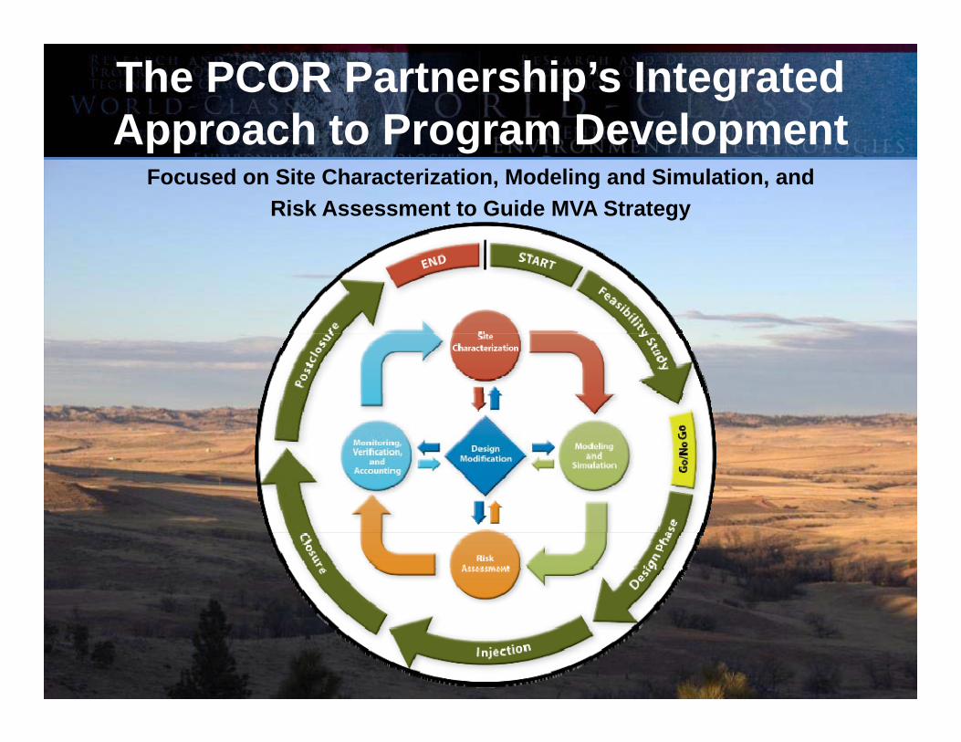
The PCOR Partnership’s Integrated Approach to Program Development
Focused on Site Characterization, Modeling and Simulation, andRisk Assessment to Guide MVA Strategy
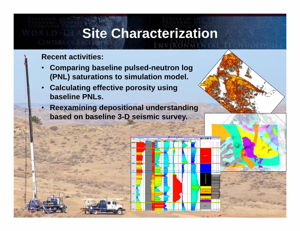
Site CharacterizationRecent activities:• Comparing baseline pulsed-neutron log
(PNL) saturations to simulation model.• Calculating effective porosity using
baseline PNLs. • Reexamining depositional understanding
based on baseline 3-D seismic survey.

Modeling and Simulation Update• Completed models:
– Version 1 (Phase 1 area)– Version 2 (full field)
• Version 3 (development under way) includes:– 3-D seismic data.– Simulation results from Versions 1 and
2.– New interpretation of depositional
environment.– Simulation/history matching to follow.
• Successfully history-matched Phases 1 and 2 of Version 2 geologic model.

How do you develop MVA strategies that are practical and meaningful at a commercial scale?
Bell Creek (above), Permian Basin Examples (below)

Research MVA and Surveillance Program Deployed at Bell Creek

Near-Surface MonitoringSoil Gas and Water Chemistry
Surveillance
Modeling and SimulationSite Characterization Assurance Monitoring
• Naturally occurring variability of soil gas and water compositions in the near-surface environment
• Provide a scientifically defensible source of data capable of monitoring for and characterizing anomalies within these environments
• Annual and interannualvariability of soil gas and water chemistries
• Near-surface environments, chemistries, and mineralogy
• Demonstrate safe/effective associated storage
• Demonstrate no impact to near-surface environments
• Geochemical modeling• Hydrogeological modeling
6.00
7.00
8.00
9.00
10.00
11.00
Nov-11 Feb-12 May-12 Aug-12 Nov-12 Feb-13 May-13 Aug-13 Nov-13 Feb-14 May-14
pH (a
vera
ge)
Date
Surface Waters
Stock Wells
Residential Wells
Monitoring Wells
Baseline Operational
CO2 Injection Start
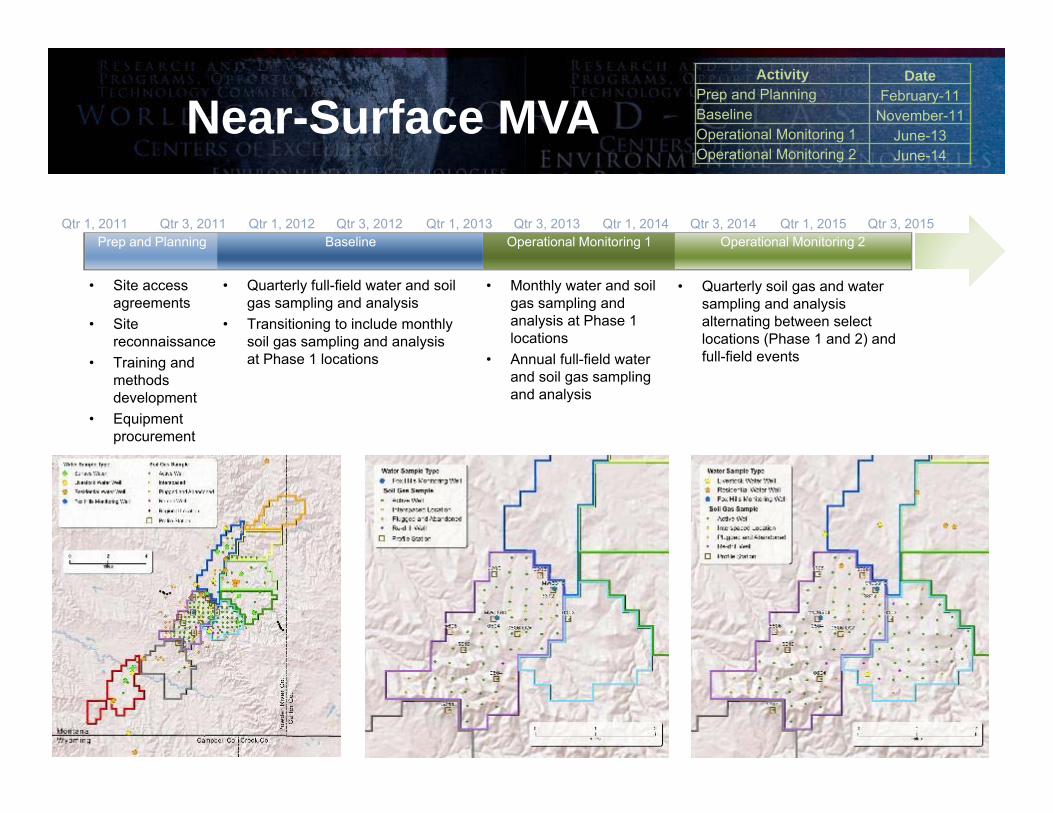
Near-Surface MVA
Qtr 3, 2011 Qtr 1, 2012 Qtr 3, 2012 Qtr 1, 2013 Qtr 3, 2013 Qtr 1, 2014 Qtr 3, 2014 Qtr 1, 2015 Qtr 3, 2015Prep and Planning Baseline Operational Monitoring 1 Operational Monitoring 2
Qtr 1, 2011
• Site accessagreements
• Site reconnaissance
• Training and methods development
• Equipmentprocurement
• Quarterly full-field water and soil gas sampling and analysis
• Transitioning to include monthly soil gas sampling and analysis at Phase 1 locations
• Monthly water and soil gas sampling and analysis at Phase 1 locations
• Annual full-field water and soil gas sampling and analysis
• Quarterly soil gas and water sampling and analysis alternating between select locations (Phase 1 and 2) and full-field events
Activity DatePrep and Planning February-11Baseline November-11Operational Monitoring 1 June-13Operational Monitoring 2 June-14

Near-Surface Monitoring Update• NO evidence of out-of-zone migration has been detected (demonstrating site
security).
• Baseline data set was acquired over 18-month period prior to injection.
• Monitoring program was sufficient to detect anomalies. Additional characterization showed they were NOT related to an out-of-zone migration event.
• First year of operational monitoring completed. Success has allowed a modified sampling program in a step toward a commercially viable, long-term strategy.
• Landowner relations key to success.

Seasonable Variability of Near-Surface Environments (aka “Spring”)

Subsurface MVA Program
16
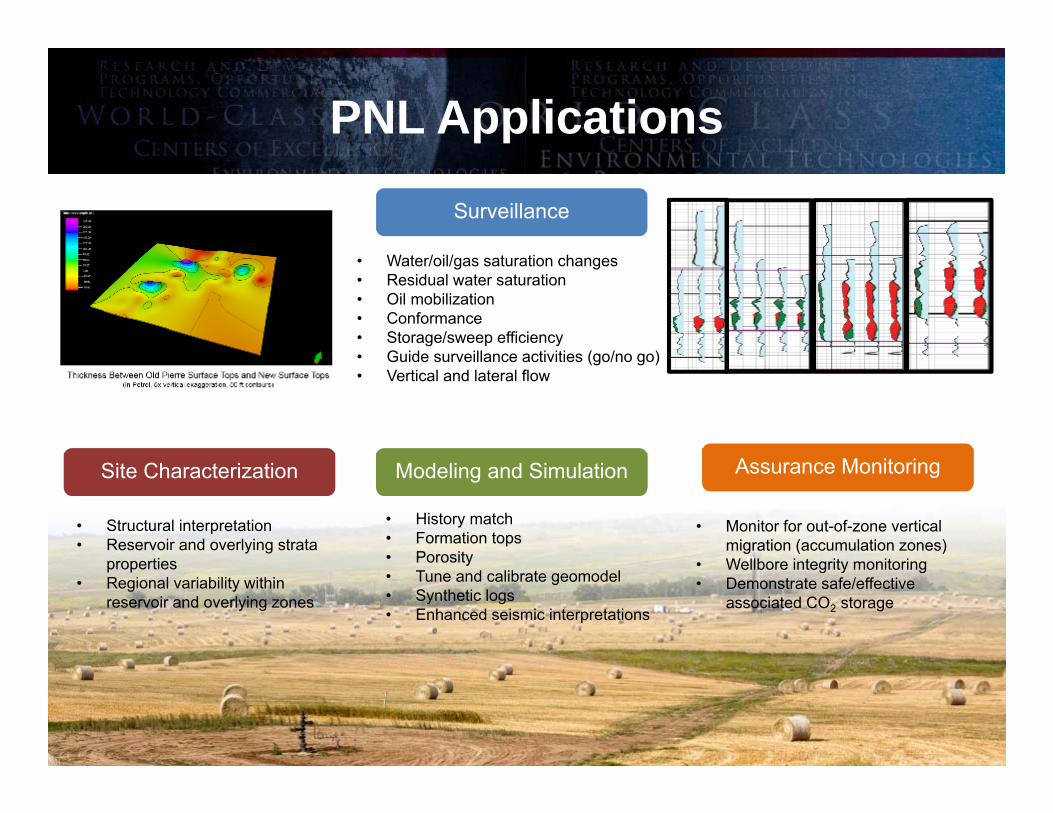
PNL Applications
Surveillance
Modeling and SimulationSite Characterization Assurance Monitoring
• Water/oil/gas saturation changes• Residual water saturation • Oil mobilization• Conformance• Storage/sweep efficiency• Guide surveillance activities (go/no go)• Vertical and lateral flow
• Structural interpretation• Reservoir and overlying strata
properties • Regional variability within
reservoir and overlying zones
• History match• Formation tops• Porosity• Tune and calibrate geomodel• Synthetic logs• Enhanced seismic interpretations
• Monitor for out-of-zone vertical migration (accumulation zones)
• Wellbore integrity monitoring• Demonstrate safe/effective
associated CO2 storage

4 Wells4 Wells 19 Wells 4 Wells
33 Wells
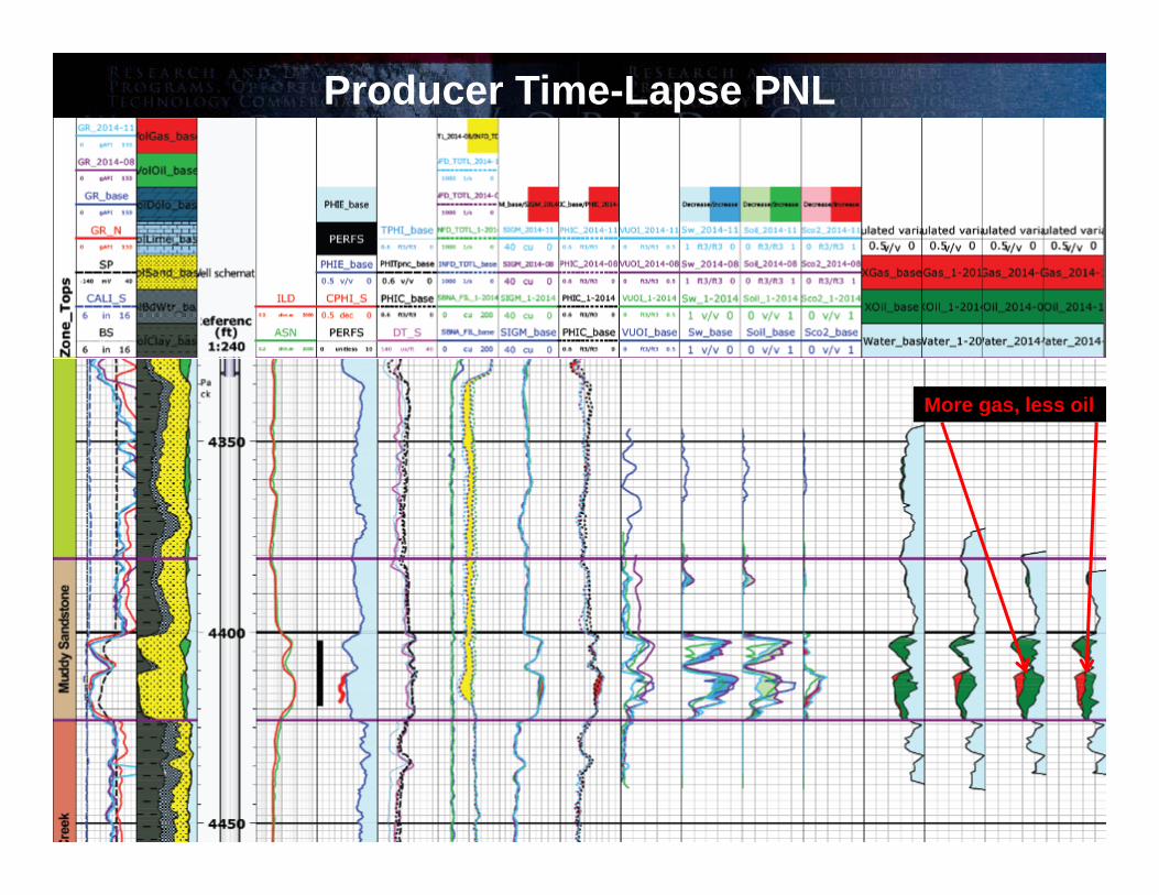
Producer Time-Lapse PNL
More gas, less oil

Injector Time-Lapse PNL
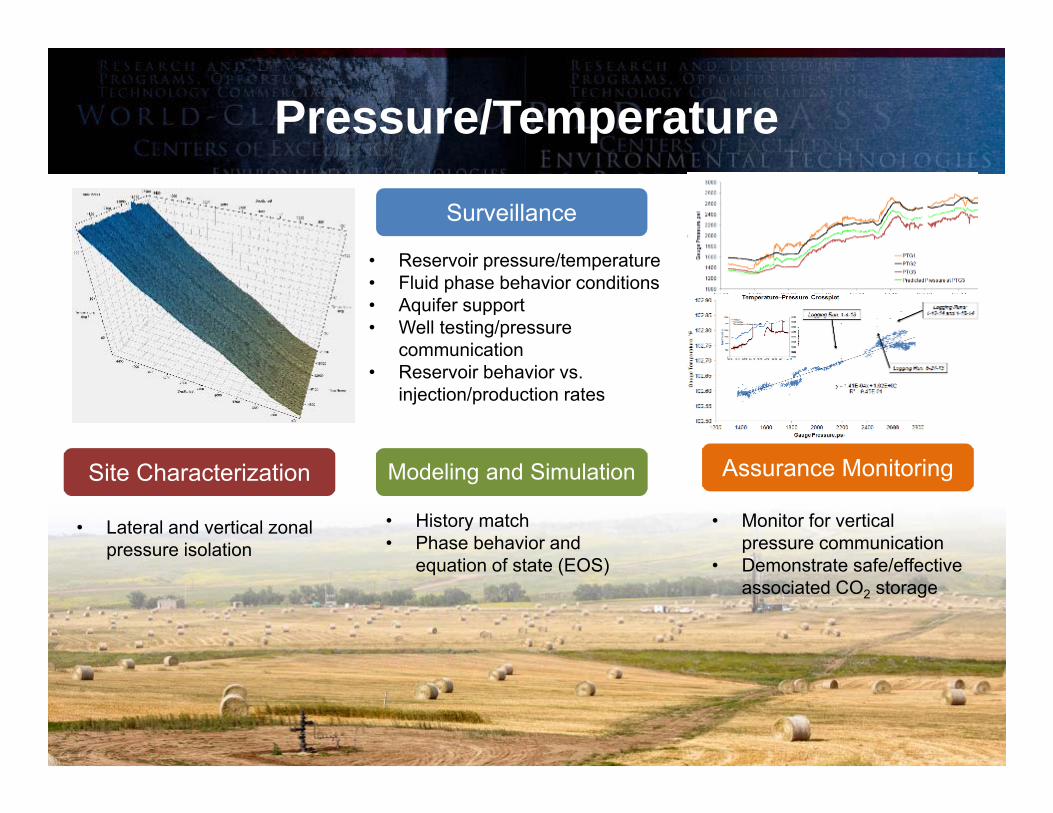
Pressure/Temperature
Surveillance
Modeling and SimulationSite Characterization Assurance Monitoring
• Reservoir pressure/temperature• Fluid phase behavior conditions• Aquifer support• Well testing/pressure
communication• Reservoir behavior vs.
injection/production rates
• Lateral and vertical zonal pressure isolation
• History match• Phase behavior and
equation of state (EOS)
• Monitor for vertical pressure communication
• Demonstrate safe/effective associated CO2 storage

Permanent Downhole Monitoring (PDM)• Three casing-conveyed pressure‒
temperature gauges (PTGs)‒ Three monitoring zones record
data at 5-min intervals:
• Casing-conveyed fiber optic distributed-temperature system (DTS) records temperature traces at 4-hr intervals:‒ DTS anchor at 4750 ft MD‒ Temperature data every 1 m
(3.3 ft)
• Installed January 2012; continuous operation since April 20, 2012.
For more information and a detailed overview of the PDM system, a videographic documentary can be viewed at www2.undeerc.org/website/PCORP/.

Geophysics Portfolio• 3-D and 4-D surface seismic
– Baseline survey (May 2013, 45 mi2)– Monitor survey (October 2014, 11.5 mi2)– 4-D analysis
• 3-D and 4-D vertical seismic profile (VSP) – Baseline survey (May 2013, 05-06 OW
and 04-03 OW)– Monitor survey (October 2014, 04-03
OW only)– 4-D analysis
• Passive seismic monitoring– Approaching 2 years of data collection– First year of data processed;
interpretation ongoing
23
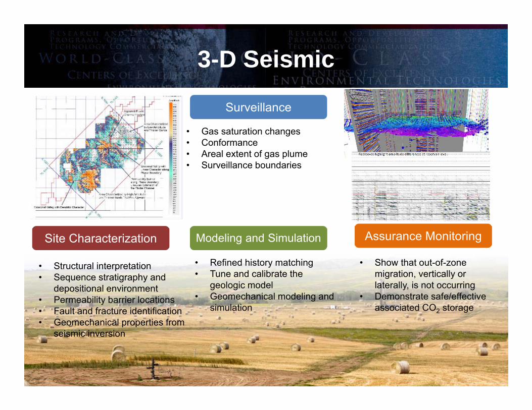
3-D Seismic
Surveillance
Modeling and SimulationSite Characterization Assurance Monitoring
• Gas saturation changes• Conformance• Areal extent of gas plume • Surveillance boundaries
• Structural interpretation • Sequence stratigraphy and
depositional environment• Permeability barrier locations• Fault and fracture identification• Geomechanical properties from
seismic inversion
• Refined history matching• Tune and calibrate the
geologic model• Geomechanical modeling and
simulation
• Show that out-of-zone migration, vertically or laterally, is not occurring
• Demonstrate safe/effective associated CO2 storage
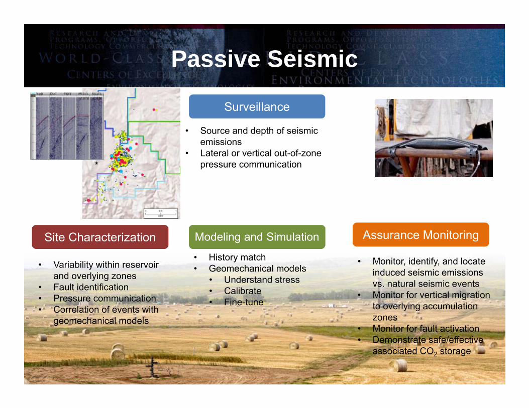
Passive Seismic
Surveillance
Modeling and SimulationSite Characterization Assurance Monitoring
• Source and depth of seismic emissions
• Lateral or vertical out-of-zone pressure communication
• Variability within reservoir and overlying zones
• Fault identification• Pressure communication• Correlation of events with
geomechanical models
• Monitor, identify, and locate induced seismic emissions vs. natural seismic events
• Monitor for vertical migration to overlying accumulation zones
• Monitor for fault activation • Demonstrate safe/effective
associated CO2 storage
• History match• Geomechanical models
• Understand stress• Calibrate • Fine-tune

Passive Monitoring• Monitoring Well 04-03 OW
– 50 three-component geophones + hydrophone cemented in the wellbore
– Total depth: 2471 ft– 15-m sensor pod spacing (49.2 ft)
♦ First level at 60-ft depth– System status e-mail every 4 hours– Data collected from May 2013 to
present♦ First year of data processed
Data Screen
Sensor Pod
GeoRes HC-W
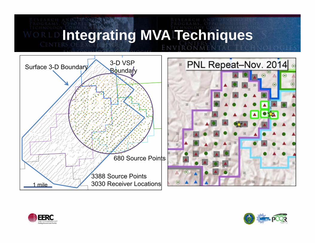
Integrating MVA Techniques
Surface 3-D Boundary 3-D VSP Boundary
680 Source Points
3388 Source Points3030 Receiver Locations1 mile
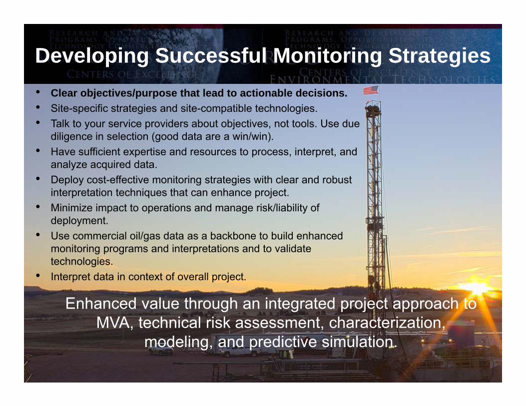
Developing Successful Monitoring Strategies• Clear objectives/purpose that lead to actionable decisions.• Site-specific strategies and site-compatible technologies.• Talk to your service providers about objectives, not tools. Use due
diligence in selection (good data are a win/win).• Have sufficient expertise and resources to process, interpret, and
analyze acquired data.• Deploy cost-effective monitoring strategies with clear and robust
interpretation techniques that can enhance project.• Minimize impact to operations and manage risk/liability of
deployment. • Use commercial oil/gas data as a backbone to build enhanced
monitoring programs and interpretations and to validate technologies.
• Interpret data in context of overall project.
Enhanced value through an integrated project approach to MVA, technical risk assessment, characterization,
modeling, and predictive simulation.
29
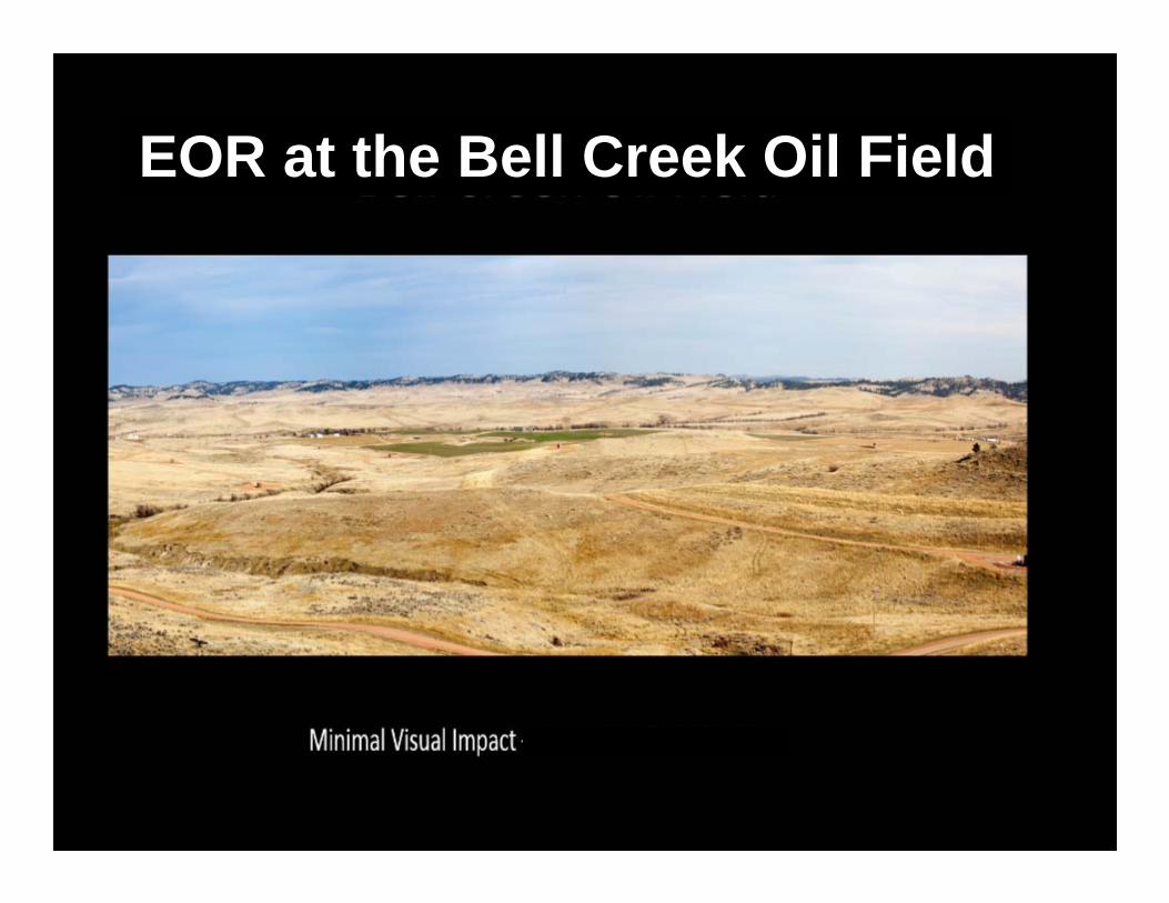
EOR at the Bell Creek Oil Field

30
EOR at the Bell Creek Oil Field
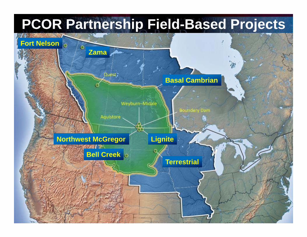
PCOR Partnership Field-Based ProjectsFort Nelson
Zama
Basal Cambrian
Northwest McGregor
Bell Creek
Lignite
Terrestrial

Fort Nelson Carbon Capture and Storage in a Deep Saline Formation
• Developed MVA plan based on site characterization and modeling and simulation activities.
• Completed best practices manual (BPM).

Aquistore Project
• CO2 sourced from the Boundary Dam power plant in southeastern Saskatchewan for injection into a saline formation.− Target zone is Deadwood Formation,
3200 m (10,500 ft) deep, >50 m (>150 ft) thick.
− PCOR Partnership activities include:− Core analysis.− Static and dynamic modeling.− Public outreach.− Participation in Aquistore Science
and Engineering Research Council (SERC).

CO2 Injection Is Under Way!
• Injection of CO2 began April 2015.
• Downhole monitoring data are being collected from multiple zones.
Ongoing Work• Update predictive simulations
with injection data in an iterative fashion (near-real-time history matching).
• Expand fine-scale model.• Optimize simulations to
maximize storage efficiency.
Image from Prairie Public Broadcasting

PCOR Partnership Outreach ActivitiesOccur at Local and Regional Levels

Other PCOR Activities
• Developing a project capstone report (due November 2016). • Publishing special edition of the International Journal of Greenhouse Gas Control (target mid-
2016).– Special edition focused on “The Nexus of Water and CCS.”– Solicitation for papers is being prepared and will be released soon.
Regulatory• Participation in Interstate Oil and Gas Compact Commission activities.• 7th Annual PCOR Partnership Regulatory Roundup held in July 2015. • Preparing document on permitting for CO2 storage in the PCOR Partnership region.
Regional Characterization• Four value-add reports completed in the last year. Three in development.• Paper submitted and accepted to a journal (Environmental Science and
Technology).

Thank You!
Questions?

Contact Information
Energy & Environmental Research CenterUniversity of North Dakota15 North 23rd Street, Stop 9018Grand Forks, ND 58202-9018
World Wide Web: www.undeerc.orgTelephone No. (701) 777-5355Fax No. (701) 777-5181
Charles Gorecki, Deputy Associate Director for [email protected]
AcknowledgmentThis material is based upon work supported by the U.S. Department of Energy
National Energy Technology Laboratory under Award No. DE-FC26-05NT42592.
DisclaimerThis presentation was prepared as an account of work sponsored by an agency of the
United States Government. Neither the United States Government, nor any agency thereof, nor any of their employees, makes any warranty, express or implied, or assumes
any legal liability or responsibility for the accuracy, completeness, or usefulness of any information, apparatus, product, or process disclosed or represents that its use would not
infringe privately owned rights. Reference herein to any specific commercial product, process, or service by trade name, trademark, manufacturer, or otherwise does not necessarily constitute or imply its endorsement, recommendation, or favoring by the United States Government or any agency thereof. The views and opinions of authors
expressed herein do not necessarily state or reflect those of the United States Government or any agency thereof.

Supplemental Slides

RCSP Program Goals• Develop technologies that will support the industry’s ability to predict
CO2 storage capacity in geologic formations to within ±30%:– Conducting pilot tests and demonstration projects in hydrocarbon reservoirs, saline
formations, and coal seams to study sweep and storage efficiency in each project.– Evaluating multiple oil fields, saline formations, and coal seams in the PCOR Partnership
region, and estimating volumetric and dynamic storage resource through characterization and simulation.
– Sharing lessons learned from our projects with the other partnerships and participating in all RCSP Storage Capacity working group.
– Conducting complementary projects that utilize the lessons learned from PCOR Partnership projects to improve the methodologies used to estimate CO2 storage resource in saline formations and hydrocarbon reservoirs.
- Joint IEA Greenhouse Gas R&D Programme (IEAGHG) and U.S. Department of Energy (DOE) project – Development of Storage Coefficients for Carbon Dioxide Storage in Deep Saline Formations, Report No. 2009/13 (completed 2009)
- DOE project – Optimizing and Quantifying CO2 Storage Capacity/Resource in Saline Formations and Hydrocarbon Reservoirs (active 2012–2015)
- Joint IEAGHG and DOE project – CO2 Storage Efficiency in Deep Saline Formations (completed 2014)
41

RCSP Program Goals (continued)
• Develop technologies to improve reservoir storage efficiency while ensuring containment effectiveness: – Testing new techniques or combining techniques to better account for injected
CO2 in the demonstration tests.– Evaluating different injection strategies through simulation and field activities to
determine the optimal strategies for both improving storage efficiency and hydrocarbon recovery, with commercial partner Denbury Onshore LLC (Denbury) providing all resources for CO2 injection.
• Develop and validate technologies to ensure 99% storage permanence: – Developing and implementing an adaptive management approach to project
management that integrates site characterization, modeling, risk assessment, and MVA throughout a project’s life.
– Evaluating the existing technologies used to monitor, verify, and account for the injected CO2 to determine detection limits and the ability to meet the RCSP Program goals.
– Testing new techniques or combining techniques to better account for injected CO2 in the demonstration tests.
42

RCSP Program Goals (continued)• Develop BPMs for MVA and assessment; site screening, selection, and
initial characterization; public outreach; well management activities; and risk analysis and simulation:– Contributed technical expertise and lessons learned in the development of all the
RCSP BPMs created to date.
43

– The PCOR Partnership will develop several BPMs throughout the course of the program, including the following:♦ Bell Creek Test Site – Site Characterization ♦ Bell Creek Test Site – Simulation♦ Bell Creek Test Site – Monitoring for CO2
Storage and CO2 EOR♦ Fort Nelson Test Site – Feasibility Study ♦ The Nexus of Water and Carbon Sequestration
Activities ♦ Permitting
– Developed a videographic BPM entitled “Installing a Casing-Conveyed Permanent Downhole Monitoring (PDM) System” (draft under review).
44
RCSP Program Goals (continued)