the pipe crawler - eiki martinson pipe crawler eiki ... the internal pipe network may still be...
TRANSCRIPT

The Pipe Crawler
Eiki Martinson Student Mechanical & Electrical Engineering: Florida Atlantic University
Mark Miller
Student Electrical Engineering: Florida Atlantic University
Sheraz Wasi
Student Electrical Engineering: Florida Atlantic University
Primary Advisor: Tom Kelly
Director of Technical Services: Florida Atlantic University

Abstract A number of experimental studies have explored the concept of robots that travel inside
pipe networks for purposes of inspection, cleaning, or repair. The authors undertook the design
and implementation of such a robot as a senior Engineering Design project with the aim of
investigating several new variations on this idea. A teleoperated platform capable of negotiating
pipe elbows and vertical sections is presented; this mobility is made possible using a set of free-
spinning wheels, pitched like the blades of a turbine, which are rotated coaxially with the pipe,
providing forward propulsion in the manner of a turning screw. The project also features a
method of navigation using wheel odometry to determine distance and recently developed
IMEMS (Integrated Micro Electro-Mechanical Systems) gyroscopes to measure yaw, pitch, and
roll. To aid in the troubleshooting of pipe defects, this system presents the operator with the
current location of the robot and a map of the path it has traveled. Although some of the project
goals were not completely fulfilled, efforts to correct any remaining deficiencies are ongoing.
ii

Acknowledgments Team six is most indebted to its principal advisor, Mr. Tom Kelly, Director of Technical
Services for Florida Atlantic University. Mr. Kelly’s incredible diversity of knowledge on such
widely-separated topics as metal fabrication, communications, and microprocessors provided
invaluable guidance; even more important was his unquenchable energy and apparently endless
ability to tolerate our presence in his lab, which was to house the project from beginning to end.
Although he arrived in the last weeks of the semester, the assistance of Jeff Webb, master
machinist of FAU Mechanical Engineering, proved invaluable. Several critical parts could not
have been made without his extensive experience, patience, and skill. Would that he had been
here sooner.
We must honor the generous attitude of Analog Devices, Inc., towards the poor and
downtrodden – especially those college students that could not afford numerous gyroscopes,
accelerometers, and development boards for all of these without Analog’s splendidly open policy
of free evaluation samples.
However, it is also necessary to thank those whose work helped to alleviate the effects of
Analog’s other policy, that of rigorous insistence on designing surface-mount devices. Leading
the efforts to get those devices connected to something useable were Jim Paolantonio of
Sensormatic Electronics and John Marsinka, solder-wizard of the FAU HDTV Lab.
Kirk Little, student and de facto machinist of the Department of Mechanical Engineering,
deserves our praise for, despite already working twice as long as he received compensation for,
finding the time to do several important machining operations for us.
No electrical project at FAU would come to fruition without the services of Hank Van
Sant, Lab Manager of the Electrical Engineering Department. His knowledgeable counsel,
readiness to assist students, and endless stock of components are greatly appreciated.
The team would like to thank Eiki’s father Mart Martinson, for guidance (and the
manufacture of several plastic parts), a garage equipped with the most esoteric tools and
components, and a garage refrigerator equipped with the most esoteric of world beers.
FAU Ocean Engineering’s laboratory staff should be mentioned for allowing us to
experiment with one of their video cameras, which turned out to be perfect for our needs.
iii

For worthy advice and excellent moral support, we are grateful to the members of this
semester’s Walking Robot team, especially Danny Morris, whose practical experience saved us
time and trouble more than once. This will in no way dissuade us, however, from taking our
revenge for certain pranks committed against our robot.
Finally, we should acknowledge the three coordinating professors of the FAU
Engineering Design class, Dr. Bassem Alhalabi, Dr. Ming Huang, and Dr. Daniel Raviv, for
pointing the way toward funding, providing an opportunity for the members of team six to meet,
and facilitating the development of this project with advice and encouragement.
iv

Table of Contents
I. Introduction . . . . . . . . . . . . . . . . . . . . . . . . . . . . . . . . . 1
Statement of the Problem 1
Background 1
Purpose of the Project 2
Overview of This Report 2
II. Design Approach . . . . . . . . . . . . . . . . . . . . . . . . . . . . 3
Mechanical and Structural Design 3
Navigation System 8
Microcontroller and Data Communications 12
Video Camera 14
Power Supply and Distribution 15
User Interface 17
III. Results . . . . . . . . . . . . . . . . . . . . . . . . . . . . . . . . . . . . 19
Mechanical Construction 19
Electrical Systems 26
Overview of Final Implementation 29
IV. Conclusions . . . . . . . . . . . . . . . . . . . . . . . . . . . . . . . . 30
V. Recommendations . . . . . . . . . . . . . . . . . . . . . . . . . . . . 31
v

List of Figures
Fig. 2-1 Early attempt at guide wheels using angled wheel mounts actuated by one
large compression spring.
4
Fig. 2-2 Screw drive concept. 5
Fig. 2-3 Screw drive powered model. 8
Fig. 2-4 Definition of axes for inertial navigation. 9
Fig. 2-5 The relationship between displacement, velocity, and acceleration. 10
Fig. 2-6 Photoreflector disk patterns of different resolutions. 11
Fig. 2-7 H-Bridge circuit. 13
Fig. 2-8 Power supply. 17
Fig. 3-1 Final robot, showing seven articulated segments. 19
Fig. 3-2 Drawing of wheel unit assembly. 20
Fig. 3-3 Assembly of hub and wheel units. 21
Fig. 3-4 Drive hub with gear, shaft, and bearing. 22
Fig. 3-5 Spur gear adapter. 22
Fig. 3-6a
and b
Drive motors featuring rear mount point for articulation. 23
Fig. 3-7 Articulation, featuring universal joint and stiffening springs. 24
Fig. 3-8 Video camera and transition section. 25
Fig. 3-9 Payload cage, showing spring mounts and electronic components. 25
Fig. 3-10 Microcontroller program flow. 28
Fig. 3-11 Final Pipe Crawler. 29
Fig. 3-12 Routing of wires through drive section. 29
Fig. 3-13 Tether end of robot. 30
vi

I. Introduction
Statement of the Problem Plumbing networks, like any other structure, are vulnerable to damage from various
sources: thermal cycling (especially when ground freezes around the pipe), mechanical impacts
or vibrations, corrosion, etc. Pipes can fill or clog with debris, sediments, or, as with the zebra
mussel infestation in the northeast United States, living organisms. Smaller fluid systems, such
as those serving residences, may be repaired with easy, low-cost methods; in many cases it may
be best to simply replace the pipes. Operators of larger, complex systems, however, frequently
need some better way of dealing with plumbing failures. For instance, it is not cheap to replace
large diameter pipes; it is even worse if hundreds of meters of pipeline must be unearthed to
determine which section is responsible for a drop in pressure. Preventative inspection can be
another difficult requirement of industrial users: critical systems or those serving sensitive
machinery may have to be inspected periodically, to ensure the safety of human users or to
prevent damage to expensive systems.
It is possible to detect cracks or corrosion thinning in plumbing with various methods of
non-destructive testing, such as eddy-current or ultrasonic sensors, but these require access to the
outside of the pipes; difficult and costly in many situations, such as long, buried lengths.
Furthermore, this does not address the problem of clogging or fouling. In many such
applications, an internal inspection solution may be preferable. If a robot were designed to travel the length of the pipe and conduct such inspections, it
might have other uses as well. For instance, it could carry a cleaning mechanism or manipulators
to remove foreign objects. It could pull electrical or communications cables through conduits.
Such a machine has potential as a life-saving tool also: when buildings collapse, due to
earthquakes or other disasters, the internal pipe network may still be navigable for a pipe-
crawling robot, which could carry video cameras or microphones to locate signs of humans
trapped below.
Background A survey of existing pipe-inspection robots has been conducted to assess the feasibility of
this project and to determine what might be the best approach to accomplishing them. It was
1

found that several pipe-inspection robots have been constructed experimentally; some are even
commercially available products. The simplest of these (and consequently the most numerous in
the market) are platforms resting on wheels or tractor treads underneath. Such robots suffer from
an inability to negotiate vertical sections of pipe. In addition, many have limited steering abilities
and may be too long to pass through even horizontal elbows. Envirosight LLC offers a series of
such robots in their line of ROVVER inspection crawlers; these are tethered four- or six-wheeled
vehicles which carry a range of video cameras and are available in sizes as small as 4 inches
(Ref. 1).
More advanced pipe inspectors are capable of traveling through vertical pipes. One of
these, developed by RoboProbe Technologies Inc., is capable of traveling through complex pipe
networks from 8 to 12 in internal diameter (Ref. 2). Three rubber track units pressed against the
walls in equilateral configuration propel this device. It is not articulated, but is short enough to
negotiate most turns. Numerous other robots, mostly research projects, have been constructed of
this type, using either tracks or wheels.
Yet more complex are vehicles that use serpentine motions or “inch-worm” mechanisms
for propulsion. These have shown promise but remain experimental. A project by North Carolina
State University uses pneumatic mechanisms at either end of the robot to grip the walls of the
pipe, while an expanding center section produces motion in stages (Ref. 3). A “robot snake” by
the Institute for Autonomous Intelligent Systems uses a sinusoidal motion and a large number of
wheels along its length to propel itself in an extremely flexible way. (Ref. 4)
Purpose of the Project This project is intended to produce a robot capable of traveling through a network of
pipes for the purpose of inspection from inside.
Overview of This Report Methods employed by the Pipe Crawler team are described in section II: Design
Approach; further subdivisions are restricted to the design of each subsystem. The fruit of these
efforts is included in section III: Results, which contains a description of the mechanical and
electrical systems of the robot, as well as an overview of the final implementation.
2

II. Design Approach As the Crawler is somewhat closer to a research project than a design for a commercial
product (although such an application should not be ignored completely), there are few well-
known solutions to be made use of; even worse, the dynamics of this robot are too complex and
influenced by too many factors for simplified analyses to be very useful. Therefore, the
development of the Crawler embodies an approach to design and implementation which
emphasizes experiment and rapid construction of models to determine the success of new ideas
in meeting the project criteria.
These goals are explicitly defined: first, the robot should be a general platform for
traveling into a pipe network and returning along the same route, capable of mobility in
horizontal and vertical sections of pipe, and stable in either without applying power. It should
also be able to negotiate certain pipe fittings, especially elbows of various angles (commonly 90
and 45 degrees). Due to the availability and widespread use of 6 in. diameter PVC sewer and
drainage pipe, the Crawler will be designed to accommodate this environment. A human user at
the entrance of the fluid system should be able to remotely control the robot using a base device
that provides some interface. This can be connected to the robot via a tether, which carries
power, bi-directional communications, and a structural cable for extracting the Crawler in case
of mechanical failure, all designed with aim of supporting a 100 foot range. Tele-operation is
aided by a video camera at the front of the robot and a navigation system that can track progress
through the pipe-network and present this information to the user in the form of a constantly
updated map on a computer screen. Finally, the Crawler should provide some measure of future
expandability, especially the ability to add payloads such as sensors for testing the integrity of
pipe walls.
Mechanical and Structural Design Three mobility requirements can be defined from the goals above: first, the robot must be
able to move forward and backward (since it will have to travel back to the entrance without the
rather difficult challenge of turning around inside). Second, a capability for travel in vertical pipe
sections is necessary; as part of this, it is best for the robot to be statically stable or able to
maintain position in a vertical pipe without the use of motors or other powered devices. Third,
the robot should be able to move through turns such as elbow fittings.
3

Many possibilities exist for a solution to the first condition above; therefore it is little
help in constraining the design. More difficult to solve is the second requirement, that of vertical
travel. Putting aside complicated and unreliable solutions such as rockets or fluid propulsion, the
robot cannot move without exerting a force against the pipe walls. Further neglecting exotic
possibilities such as vacuum suction (defeated by rough pipe surfaces) or electromagnets (only
successful in iron pipes), any such robot traveling in a vertical pipe has to rely strictly on
mechanical friction against the pipe walls to maintain its position. Since friction only exists
when a normal force is applied to the surfaces, and gravity will not help in a vertical section, the
robot has to push against opposing walls of the pipe.
Fig. 2-1. Early attempt at guide wheels using angled wheel mounts actuated by one large compression spring.
One method of doing so is to force wheels or tractor-tread devices outward using springs
or other devices; an early experimental model is shown in fig. 2-1. The optimal, exactly
constrained version of this design consists of three contact points in an equilateral configuration.
Such wheels or tracks, if freewheeling, could guide the robot along the pipe. If driven by motors,
these could provide forward propulsion as well. However, the vehicle must be able to travel
around curves; in this case, the wheels along the outside of the turn must travel further than the
inner wheels, necessitating a differential mechanism, which does not exist for the cylindrical
three-dimensional case. Therefore, each wheel (or track) will have to be independently driven
and the ratio between wheel speeds electronically controlled.
This scheme does not achieve the ideal of functional independence, however. Forward
drive and guidance are now achieved using the same system, necessitating greater operator
4

involvement; furthermore, a system consisting of three driven wheels each with its own motor
and drivetrain is needlessly complex. An alternative design would separate the functions of drive
and guidance. Using the same equilateral configuration of free-spinning wheels for guidance, it
is necessary only to provide a forward force, desirably in some way that does not interfere with
that guidance. One such method is a “screw drive” using a rotor to which are attached three (or
any integer greater than one) freely spinning wheels forced against the sides of the pipe by
springs. Suppose that a motor drives the rotor itself, and that the individual wheels have been
displaced by some small angle from the plane of the rotor. This mechanism, illustrated in the
figure below, is analogous to a large screw being turned inside the pipe and consequently
moving forward.
Fig. 2-2. Screw drive concept.
A kinematic analysis can yield insight into the performance of such a screw drive. Each
wheel is displaced from the plane of rotation of the screw rotor by some angle θ . Over one
revolution of the rotor, each wheel will travel along the inside of the pipe by a length equal to the
circumference of that circle, or Rπ2 , where R is the radius of the pipe interior. Therefore, the
screw drive will move forward each revolution by a distance given by:
θπ tan2 RD = Eq. 2-1.
Forward velocity of the screw drive is determined simply by multiplying this distance by the
5
number of revolutions per minute of the rotor:
θπ tan2 RNv = Eq. 2-2.
Obviously, greater forward speed is available simply by increasingθ . However, this will
also increase the torque required of the drive motor. That presents the option of adjusting the
pitch of the screw wheels to act as a sort of variable gearbox, increasing the speed or decreasing
the load as necessary for the selected motor and the specific operating conditions. It is possible
to derive an expression for the torque required to turn the rotor, but in the absence of
manufacturer data for the tire’s coefficient of friction, this analysis would not be valuable. An
experiment can be conducted to measure the torque requirement directly, which would
necessitate the construction of a screw drive rotor.
A simple wooden model, using rubber wheels from LEGO toys, was built and mounted
on a length of threaded rod with a handle or moment arm at the end. This arrangement was
inserted into a piece of PVC pipe such that the end of the rod with the handle attached protruded
from the entrance. A spring scale was used to apply a known force onto this arm; while the
experimenter slowly increases the amount of force, the scale is observed and the measurement in
pounds recorded at the moment when the screw drive begins to turn. This weight, multiplied by
the length of the moment arm, yields the torque required to turn the screw drive. In this case, the
measured force of 3.5 pounds, multiplied by the 2 inch handle, gives a torque of 7 in. lbs. ×
It is necessary, of course, to treat such a result with caution; there are many
circumstances which could increase the resistance of the screw drive dramatically. As such, it is
advisable to select a motor with an ideal running torque (that is, the point in the speed-torque
curve which gives the greatest efficiency) somewhat greater than the torque measured above, to
allow for the effect of the load contributed by the rest of the robot, and to ensure that the stall
torque (typically several times greater than the ideal torque) would remain higher than any
resistance encountered in operation.
One final difficulty is presented by the screw drive: as the wheels extend to the wall of
the pipe itself, it is impossible for anything which does not rotate to pass around it. Electrical
wiring which has to extend from end to end of the robot cannot simply be routed around the hub
as with guide wheels - the piston units would catch that wire and destroy it. Furthermore, it is
desirable to pass some structural, non-rotating member to both sides of the screw drive, so that
the entire robot is not made to rotate. The only solution is to make provisions for passing through
6

the center what cannot go around. Practically, this means that the screw hub must rotate on a
hollow shaft and that this shaft must have a large enough diameter to accommodate the wiring.
Worse yet, since hollow-shaft motors or gearboxes are very rare (usually custom-made for
specialized applications), it is necessary to drive the hub by gears or pulleys attached to a motor
that is somewhat offset from the center.
As mentioned above, the third condition for complete mobility in the pipe environment is
the ability to travel around bends or elbow fittings. Fulfilling this criterion necessitates a short
vehicle; the ends of a longer robot will collide with the walls of the pipe when the turn is
attempted. However, such a restriction does not leave enough room for the payload,
microcontroller, video camera, motors, and other systems required by the robot. For this reason,
it is better to design a robot in several sections, with flexible articulations in between. Such an
arrangement can be as long as needed to accommodate any electrical systems or other
components, provided that each segment is small enough to travel through the tightest elbow.
Obviously, this linkage should be flexible enough to allow the segments to traverse the
elbow; however, experiments reveal that some methods of articulation are too flexible, causing
the robot to buckle when pushed from behind. In practice this will occur with segments which
lead the front propulsion unit, where front is defined according to the direction in which the
robot is traveling. If the force contributed by both screw drives is not exactly equal, sections in
between may also be affected. Any such instability will result in guide wheel hubs which are not
parallel with the pipe - a dangerous situation that can cause the wheels to jam and, consequently,
the motor to stall.
The first attempt at optimizing the flexibility of a linkage is seen in fig. 2-1 above; here,
three segments are joined with lengths of clear vinyl hose. This proved unsatisfactory, as the
hose was slightly too stiff, and, furthermore, had acquired an inherent curvature as it had been
coiled on a roll during storage. Consequently, the curved hose forced the segments to buckle,
while simultaneously being too stiff to pass the elbow! A second model provided the solution:
very flexible universal joints can be bent to extreme angles to allow passage through the bend,
while an arrangement of springs can be used to stiffen the joint, preventing instability. This has
the added virtue of being adjustable, as the springs can be tightened further or replaced to
experiment with different levels of flexibility.
7

Fig. 2-3. Screw drive powered model.
Figure 2-3 depicts a test model featuring an early screw drive, one set of guide wheels,
and the flexible linkage without stiffening springs (this model revealed the need for them). An
important addition to this version is the triangular arrangement of caster wheels mounted at the
front. This is designed to have a smaller total diameter than the guide wheels, and thus serve as a
sort of transition into bends. It was observed that the caster wheels do not actually rotate during
use, but, being composed of very hard plastic, merely slide against the walls of the pipe. It is
therefore simpler to outfit the front (and rear - since the robot is designed to travel in both
directions) with a plastic dome or ring of similar diameter.
Navigation System One of the innovative features of the Pipe Crawler is the ability to trace its movements
inside a pipe, thus creating a map of the pipe's layout. In general, to fix an object's position in
space (and the history of this position, if recorded with sufficient frequency, constitutes a map of
the route traveled), the motion of the object along three orthogonal axes, X, Y and Z should be
measured. However, common methods for doing this (except for GPS and other systems which
make use of external references, rejected here for reasons of cost, size, power consumption,
insufficient resolution, and possible inability to penetrate ground or certain type of pipe walls)
are mounted on the vehicle itself and thus determine displacements with respect to the current
orientation (neglecting the possibility of gyroscopically stabilized gimbal mounts, which are far
too bulky and complex for this application). Therefore, in order to use three linear displacement
8

measurements to track position, it is necessary also to determine the orientation of the object, so
that future movements along the three unfixed position axes can be correctly interpreted with
respect to some absolute coordinate system (defined most conveniently at the entrance of the
pipe network). Orientation must also be measured with respect to three orthogonal axes; it is
simplest to do so about the three linear displacement axes X, Y, and Z, in which case the
resulting angular deflections are commonly called pitch, yaw, and roll.
x
y
z
roll
pitch
yaw
Fig. 2-4. Definition of axes for inertial navigation.
One way of measuring changes in position and orientation is inertial navigation, most
commonly using three accelerometers for the three axes of linear motion, and three gyroscopes
for the three axes of angular displacement. Unfortunately, accelerometers present several
problems that complicate their use. First, accelerometers measure acceleration, so they can be
affected by gravity. Accelerometers of a certain type (the most common, lowest cost, and most
compact type) will read 1 g if oriented normal to the earth’s surface. Therefore, the range of
additional acceleration, resulting from the motion of the device, that can be measured is limited;
this effect also complicates the interpretation of the data, making it necessary to track the
“down” direction and subtract the effect of gravity vectorially from accelerations along each of
the three axes.
9

Second, using acceleration measurements to determine displacement requires a double
integration, not a terrible burden computationally, but liable to produce inaccurate results if
sampling rates are low (and, as is seen later, they will be). Consider the hypothetical plots of
displacement, velocity, and acceleration in fig. 2-4. In this simple constant velocity case, it is
easy enough to sample the displacement (provided that such a sensor exists), as this signal
contains only low frequency components. Reproducing the velocity plot requires a higher
sampling frequency, as any discontinuity will produce harmonics at infinite frequencies. The still
sharper plot of acceleration, represented by two impulses in this idealized example, is also
theoretically impossible to capture exactly; practically, it will require a still higher sampling rate
to provide acceptable results. For these reasons, it was decided, after some initial experiments, to
abandon the use of accelerometers in this project.
a
v
x
t
t
t
Fig. 2-5. The relationship between displacement, velocity, and acceleration.
Furthermore, the unusual environment of the pipe network makes a simpler scheme
possible. Since the robot travels through the pipe like a train travels on rails, there is no
possibility for the robot to move along axes orthogonal to its longitudinal axis. Therefore, if the
vehicle's linear displacement along this axis is recorded, together with any changes in orientation
that occur when bends or other fittings are encountered, a map could be drawn of the path the
vehicle has followed. Therefore the six degrees of freedom to be tracked in the general case is
10

reduced to only four degrees of freedom, three of angular displacement, to be measured by
gyroscopes, and one of linear displacement with respect to the long axis of the pipe – and this
can even be determined using direct methods such as wheel odometry or measurement of the
length of the deployed tether.
The most practical method is the use of an optical encoder on the robot itself, turned by
one of the guide wheels and consisting of either an IR emitter/phototransistor pair with a slotted
disc, or an IR photoreflector aimed at a disk colored with strips of different reflectivity. Because
of the design of the Pipe Crawler's wheels, it is easiest to mount an IR photoreflector directly on
the wheel mount. First, a disc with an alternating pattern of black and white "pie slices" is
attached to the wheel. With the photoreflector placed a few millimeters away from the disc, its
output signal goes high when opposite a light colored segment and low when observing a dark
segment. When the wheel is spinning, the signal is compose of a series of pulses that can be
counted to determine the number of wheel rotations, and, subsequently, the distance traveled.
Fig. 2-6. Photoreflector disk patterns of different resolutions.
Several types and models of electronic gyroscopes were investigated, but most were
either too large or too expensive for this application. Only one class of devices, the recently
developed IMEMS (Integrated Micro Electro-Mechanical System) gyroscopes made by Analog
Devices, Inc., were small, affordable, and accurate enough (Ref. 5). These devices are simple to
use and interface with, as Analog Devices employs a new micro-machining technology that
allows a functionally complete angular rate sensor, with all of the required electronics, to fit on a
single 20-pin dual-inline-package device (indeed, the gyroscope itself is available in an even
smaller surface mount device, about the size of a watch battery, but the DIP package was
selected so that it could be easily interfaced to). The gyroscope's output signal is a voltage
proportional to the angular rate about the axis normal to the top surface of the chip. When
connected to an analog-to-digital converter, the instantaneous angular rate of each gyro can be
sampled and recorded by a computer; a numerical integration of this data will results in the
11

angular displacement. Sample all three gyros, where one is positioned to read each of pitch, yaw,
and roll displacements, and the robot's orientation in three dimensions can be tracked.
Microcontroller and Data Communications In order to acquire data from the navigation system sensors and transmit this to a
personal computer at the entrance of the pipe for processing and display, it is necessary to
include a small microcontroller or other computer on-board the robot. This would have to
accomplish the A/D conversion of the sensor voltages, count the pulses at the photoreflector
output, and provide some mechanism for communications over a wire or set of wires, preferably
with a minimum of external hardware. Due to the previous experience of team members with
Motorola microprocessors, specifically the many variants of 68000 and the later HC11/HC12, a
Motorola MC9S12DP256 single-board computer was selected. The DP256, one of Motorola's
newest models, is very capable and well suited for this application: it features 16 channels of 10-
bit A/D conversion, four 8-bit pulse accumulators (useful for counting photoreflector pulses
without the need for high-speed polling of conventional inputs), two full-duplex asynchronous
serial communication modules, eight 8-bit pulse width modulated outputs, on-board EEPROM,
several general purpose I/O ports, and more.
Pre-manufactured printed circuit boards are available from several manufacturers that
house the DP256 chip, a voltage regulator, and header pins for easy access to all of the
microcontroller ports. Some also provide additional RAM and other electronics to augment the
capabilities of the microcontroller, or integral breadboards for prototyping and experiments.
Although such a product proved useful during the development of software for the Pipe Crawler,
the space constraints of this robot make larger, more complex boards impossible. Instead, a
suitable single-board computer was found in the EVBplus MiniDRAGON (Ref. 6). This is an
economical and extremely compact (2.2 in. by 3.2 in., almost exactly the size of a credit card!)
HC12 product, which features a RJ-12 plug like that used in telephone handsets for interface
with the serial port of any PC.
Aside from its usefulness in data acquisition and transmission, the on-board
microcontroller is quite necessary for receiving control signals from the operator and powering
the appropriate drive motors. Unfortunately, DC motors require quite high power to function
properly, but microcontroller I/O ports are only capable of power levels appropriate to logic
12

circuits. Therefore, an additional circuit is needed which will interface with the microcontroller
while providing the necessary power to run the motors. One possible and much used design,
called an H-bridge, is made up of four high-power transistors with the motor connected between
them, in a configuration that resembles a capital H.
Q1Q2
VCC
DC MOTOR
1 2
Q4Q3
VCC
Fig. 2-7. H-bridge circuit.
When transistors Q1 and Q4 in Fig. 2-1 are turned on, by receiving logic high voltage at
their gate inputs, current will flow through the motor as indicated by the arrows, causing it to
turn. The DC motor can also be made to run in the opposite direction by merely turning off Q1
and Q4, and turning on Q2 and Q3 - the reverse direction is the only reason for four rather than
two transistors.
One disadvantage of this kind of H-bridge is that, since the MOSFETs are capable of
high power, the microcontroller signal must also be relatively powerful (although not as
powerful as would be needed to run the motor directly) in order to turn on the transistors;
otherwise, it will be necessary to employ a more complex circuit. Also, DC motors, being high
inductance loads, can potentially create harmful high-magnitude voltages when they are abruptly
switched off, necessitating protection diodes in the circuit.
The best way and simplest way to avoid these problems is to use an IC H-bridge which
integrates the more complex H-bridge circuit (diode protected and capable of driving large
motors while accepting only logic-level inputs) into a single compact package. The IC H-bridge
has both kinds of needed inputs, power inputs and logic inputs, integrated in a single package.
13

The required inputs are a direction control signal of logic low or high, and a PWM signal, which
contains information about the desired speed of the motors. Both signals are created by the
microcontroller, in response to control instructions received through its serial communications
interface with the user PC.
The on-board Pulse Width Modulation module on the MC9S12DP256 microcontroller is
a sophisticated system comprised of user-programmable registers that control the characteristics
of the output PWM signal, such as period and duty-cycle, and the enabling of its formation by
the module's hardware. A PWM signal is basically a periodic square wave that alternates
between logic high and logic low voltage levels. Gradations in motor speed are achieved by
varying the length of the logic high portion of the signal as a percentage of the total period,
called the duty cycle, so that the motor receives varying average voltage levels, causing it to spin
slower or faster, as the case may be. This feat is, to a large degree, not possible using relays, due
to their slow activation and deactivation times, or potentiometers that yield a varying DC
voltage, due to the necessity of a full strength voltage, albeit pulsed, at the motor coils to produce
constant shaft torque.
The serial communications module on the Motorola DP256 chip is designed to create RS-
232-compatible serial signals, allowing it to communicate with any computer system that
includes an RS-232 port. Data baud rates, as well as byte length (8 or 9 bits per byte) and parity
(even, odd, or none), are controlled by the hardware, and can be set and reset in the user
program, providing flexibility and adaptability in the design.
Video Camera It is necessary for the Pipe Crawler to provide the user with a visual assessment of its
surroundings, for two reasons: first, so that the robot can be correctly navigated through the pipe
by the distant operator; second, to allow inspection of pipe integrity, fouling, or other problems
in the plumbing network. Since no natural source of light is available, an artificial one should be
provided, or the selected video camera should be able to see in very low light conditions. In
order to examine details of the surrounding pipe, it should be able to resolve details as close as
one inch; however, the camera must also see two to three feet clearly for navigation purposes.
Since color is not of significant importance inside a pipe (and it is easy enough to
upgrade the robot should more funds become available) it was decided to use a monochromatic
14

camera. The MPJA Company offers a black and white video camera with a 1/3 inch CCD on a
single circuit board; this camera is sensitive in the infrared frequencies and is conveniently
available with already mounted infrared LEDS for illumination (Ref. 7). Although no visible
light is produced, this camera is capable of illuminating and capturing details 20 to 30 feet away
in otherwise perfect darkness. Furthermore, the focus is easily adjustable with a set screw; some
experiments revealed that text 1 inch away could easily be read while images at several feet
remained quite clear.
Transmission techniques were evaluated to find a camera that will allow the user to
receive near-real-time video. Since a tether is being used to transmit power and serial
communication for the robot, it might also be used to carry a video signal. While it is
theoretically possible to capture the video using the microcontroller and transmit the data over
the serial link, such a possibility must be rejected as the volume of information transmitted for
navigation purposes is already close to overwhelming the capabilities of this channel. It is very
much easier to include a thin cable in the tether bundle and use this to carry NTSC video
directly. A very flexible coaxial cable was found and tested over a 100 ft. length; this was
deemed suitable because it showed no appreciable signal degradation at all.
Power Supply and Distribution Power requirements cannot be estimated until the mechanical design of the robot is
almost complete, so that the loads on the motors and their consequent current draw are known. It
is also necessary to select the microprocessor, video camera, and motor driver circuits so that the
power used by each is determined. For this reason, the design of the pipe crawler’s power system
was left loosely defined until relatively late in development.
Power consumption of each device in the Pipe Crawler is obtained from their respective
specification sheets. Since no specifications for the motor is available, an idle and stall current
was measured using a power supply and an ammeter. The required information is gathered and
the power consumption of the robot is calculated in Table 2-1
15

Device Nominal voltage
Nominal current
Nominal power
Peak current
Peak power
Microcontroller 8 V 40 mA 320 mW 300 mA 2.4 WGyroscope and Optical Encoder 5 V 50 µA 250 µW 50 mA 250 mW
Motors and H-bridges 12 V 1 A 12 W 1.8 A 21.6 WCamera 12 V 200 mA 2.4 W 200 mA 2.4 W
Total Power Consumption: 14.72 W 26.65 W
Table 2-1 Power consumption of on-board devices (peak voltage is the same as nominal voltage).
Tether diameter and weight should be kept to a minimum to reduce the physical load on
the robot. For this reason some voltage drop across the power cable is considered acceptable so
that a smaller gauge wire can be used. Since 12 volts DC is the highest voltage that is required to
operate the Pipe Crawler, 12 volts will be sent on the tether, and other voltages obtained by using
regulator circuits to produce 8 and 5 volts. The DC motors can operate across a considerable
range of voltages; therefore it is more efficient to avoid regulating power to the motors by
running them on the main tether power directly. To calculate the maximum input power required
by the regulators, it is necessary to consider their efficiency:
[%]/ EfficiencyPP outin = Eq. 2-3.
By adding to the power consumed by the motors and H-bridges, the total amount of
power needed by the robot is 31.31W. As mentioned above, the gauge of the power cable should
be kept as high (keeping in mind that higher wire gauges indicate smaller diameter wire) as
possible. However, this will entail a larger voltage drop over the length of the tether,
necessitating a higher voltage power supply to ensure that the robot receives 12 volts. A 15 volt,
6 amp supply was found and outfitted with a case, switch, indicator light, and fuses (fig. 2-8).
inP
16

Fig. 2-8. Power supply.
Resistance per thousand feet of wire is given by:
)2.0/()*(%)/( IdVVDKft s=Ω Eq. 2-4.
Where %VD is the desired percent voltage drop, V the supply voltage, I the current over the
line, and d the distance from supply to load. Using this equation, and the wire gauge sizes
specified by the National Electrical Code, as quoted by Messenger and Ventre (Ref. 9), a 16
gauge wire is sufficient to carry this power, while remaining flexible enough to avoid impeding
the physical progress of the robot.
s
User Interface As mentioned above, it is necessary to provide some device that can accept control inputs
from the operator and transmit these via the serial link to the on-board microcontroller. Further,
it must simultaneously receive sensor signals from the robot, interpreting and presenting them in
visual form (and storing this information for later retrieval). The simplest way to achieve this
combination of serial communications, graphical display, data storage, and ability to accept user
inputs is obviously the personal computer, equipped with suitable software.
Some methods of programming such an application were considered. Numerous data
acquisition packages exist and are widely used in the scientific and engineering communities.
Furthermore, it is always possible to use full-featured programming languages on a lower level
to accomplish the desired goals, purchasing power and flexibility at the expense of ease of use.
First investigated in this category was the possibility of writing the application in pure C/C++, to
17

run in the UNIX environment and making use of the X Window system to provide a graphical
interface. This was deemed to be needlessly complex, as displaying any graphics at all with such
a technique requires the creation of very low-level plotting routines that directly write bytes to a
buffer in memory; plotting three-dimensional vectors is even worse, as this necessitates writing
higher-level functions for projecting points in 3-space onto a viewing plane.
Matlab was considered and rejected as its serial communications capabilities, a recent
addition, are not especially mature at this time. Labview is, of course, made for data acquisition,
but both it and Matlab suffer from their lack of a complete, rigorous programming language, as
such features have evolved rather piecemeal in Matlab and are burdened by an unnecessary and
often counter-intuitive visual programming environment in Labview; additionally, the cost of
either program is prohibitive.
Perl, an interpreted programming language widely used with Unix systems (although
available for other platforms as well), can answer many of these complaints. Most often
employed in text processing or web site applications, it is nonetheless possible, and indeed
relatively easy, to construct graphical, event-driven interfaces when certain additional modular
extensions to Perl are made use of. One of these modules, the PDL or Perl Data Language, offers
mathematical functions, highly optimized manipulations of matrix data, and three-dimensional
plotting capabilities (along with all of the buttons, scroll bars, and other amenities of the GUI)
much like those of Matlab, with the power and flexibility of C or other lower-level languages
(Ref. 10).
18

III. Results
Mechanical Construction The final robot employs seven articulated segments: two units providing propulsion, one
carrying the payload, two ‘heads’ or leading units (the nose and tail of the robot are similar to
each other to allow bi-directional travel), and two extra wheeled sections used to guide the
payload and prevent it colliding with the walls of the pipe. The figure below illustrates the
arrangement of these segments (so that the mechanical and structural components can be seen
clearly, this picture depicts the robot lacking most of the wiring and electronics that would be
added later).
Fig. 3-1. Final robot, showing seven articulated segments.
All of the wheels, whether used as guides or as part of the screw drives, are mounted in
pairs to the same piston devices, and these in turn are inserted in identical circular hubs and
secured with set screws - this providing the option of rotating the piston cylinder to achieve
19

different pitch angles in the case of the screw drive. Each piston unit consists of a hollow
aluminum tube, slotted to accept a pin in order to prevent rotation of the inner steel piston, which
is drilled at one end so that a standoff, like those used to mount circuit boards, can be press-fit
into the rod. These standoffs are available with a 6-32 UNC thread through both ends. The
wheels themselves are model aircraft tail wheels, 1.5 inches in diameter and consisting of a solid
rubber tire around a plastic hub; these ride on the unthreaded shoulder of 6-32 cap-head bolts
which are screwed into both ends of the standoff and further secured using a nut and lock-
washer. Fig. 3-2 provides a detailed, dimensioned view of this assembly.
Fig. 3-2. Drawing of wheel unit assembly.
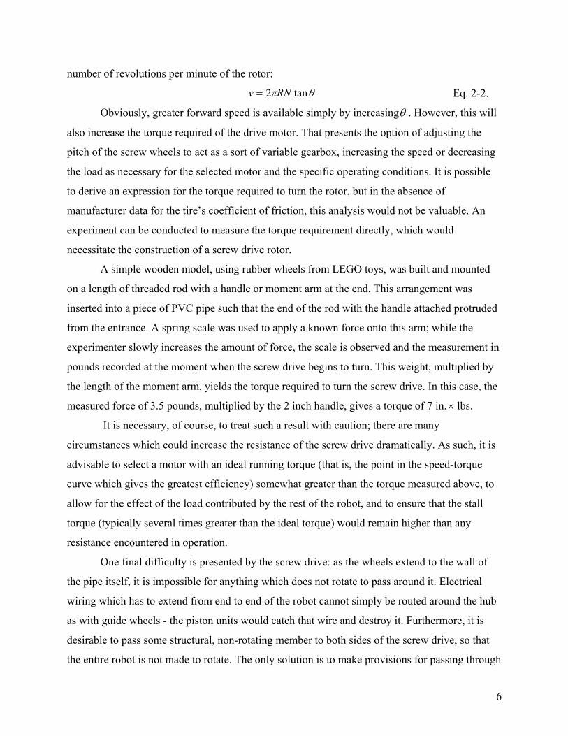
Three such piston devices and their attendant wheels are included in each hub assembly,
a photograph of which is provided in fig. 3-3 (this image depicts a guide wheel arrangement
specifically, although the drive units use identical hubs with the piston cylinders turned by some
angle). Barely visible through the guide slots are the springs which force the wheels outward
against the walls of the pipe. Also apparent are holes (tapped for a 10-32 thread) which accept
set screws for two purposes: a set screw passes through the face of each notch to engage the
wheel piston, and another set of three tapped holes are located radially to attach the entire hub to
whatever is in the center - in the case of guide wheels, an aluminum cylinder that serves as a
“backbone” and a connection to the articulations of the leading and following segments.
20
Fig. 3-3. Assembly of hub and wheel units.
Both drive units make use of assemblies identical to the one in fig. 3-3, with one
exception: inserted in the center instead of the cylinder seen above is a stepped hollow shaft with
two ball bearings and three stop collars intended to transfer thrust loads from the wheel hub
through the bearings and into the shaft, which is itself rigidly attached to the body of the robot. A
large brass ring gear is attached to the face of each drive hub using three 1/16 in. pins and three
4-40 thread screws each. This assembly, including the shaft and the recessed ball bearing (both
light press-fits of approximately 0.001 in. interference, or, in other words, the inner part has an
outer diameter 0.001 in. larger than the inner diameter of the outer part) is depicted in fig. 3-4.
21

Fig. 3-4. Drive hub with gear, shaft, and bearing.
One end of this shaft is bored to accept the articulation to the next section; the other end
is press-fit (in this case, as there are no delicate bearings to consider, a much firmer interference
fit of 0.005 in. was specified) into a plate designed to bolt onto the gearbox of the drive motor.
This motor powers the ring gear of the hub through a small spur gear; as the gear is only slightly
larger than the motor shaft itself, some difficulty was encountered in manufacturing an coupling
between the two. Fig. 3-5 depicts the final design: two 1/16 in. pins through the face of the gear
prevent shear between it and the aluminum adapter behind it, which is drilled at the opposite end
to accept the shaft. A large countersunk screw prevents vibrations or axial forces from separating
the gear and adapter during operation.
Fig. 3-5. Spur gear adapter.
22

It is also necessary to provide a means to connect the next segment of the robot to the
back end of the drive unit. Unfortunately, due to the complex geometry of the back of the motor,
there are no easy methods by which a plate or other extension can be attached here. The final
solution involves removing one of the bolts which holds the motor itself together and
substituting for this a somewhat longer bolt, so that a circular articulation mount can be held
against the motor at this one point, as seen in fig. 3-6a.
Fig. 3-6a and b. Drive motors featuring rear mount point for articulation.
To provide additional support, one of the screws which holds the motor to the gearbox is
removed, and a long standoff put in its place; finally, to prevent excess torsion (included that
generated by the motor itself) from damaging the motor, a rectangular plate is attached
underneath the drive unit between the gearbox mounting plate and the rear articulation mount, to
provide it with a third attachment point and to stiffen the whole assembly torsionally (fig. 3-6b).
Most development models had used articulations consisting of high-quality universal
joints. As six are employed in the final robot, however, it is desirable to reduce costs here, if
possible. Universal joints intended for power-transmission applications are capable of speeds and
torques far in excess of what can be expected in this application, where all that is necessary is a
sort of two-axis hinge. The least expensive implementation of such a coupler can be found in an
ordinary socket wrench universal joint, intended for flexible tightening of bolts. A 9 mm hex
socket u-joint sold under the Craftsman brand by Sears was found to be of ideal dimensions.
23

Fig. 3-7. Articulation, featuring universal joint and stiffening springs.
Revealed in the above figure is the universal joint, slid into both segments and held there
with set screws. Also apparent are three bolts, drilled at the ends to accept tension springs and
secured with nuts. The other end of the spring hooks into a plate with three holes at the outside
circumference. Other articulations are much the same, with the possible use of bolts on both
sides to connect the three stiffening springs.
As discussed above, to achieve mobility through pipe elbows it is necessary to provide
some gentle transition by means of a smooth dome or ring at the ends of the robot. Such a
structure can also be made to house the video camera, at the front, and tether connections, at the
rear. Each was constructed from two PVC end-caps that were cut short and joined by a short
length of pipe. In the case of the video camera (fig. 3-8), a large hole was cut in the center of one
of these end-caps and a clear plastic dome inserted, to allow a view out of the front of the robot.
24

Fig. 3-8. Video camera and transition section.
Finally, the microprocessor and other electrical components, which comprise the payload
of the vehicle, must be provided with mounting locations and a means by which they can be
protected against impacts. For this purpose, the centermost section of the robot is a hexagonal
cage, as hollow as possible to accept electronics inside while still structurally able to serve as
part of the “backbone” of the machine. This was constructed from two aluminum plates, serving
as end-caps, and six sturdy electronics standoffs between them, as shown in fig. 3-9. The
protruding ends of the standoffs were drilled to serve as spring mounts for this section.
Fig. 3-9. Payload cage, showing spring mounts and electronic components.
25
Electrical Systems Two DC motors drive the Pipe Crawler through the pipe. Each one requires 12 volts and
draws varying amounts of current, depending on load; the greater the torque acting against it, the
greater the current required. In an unloaded state, they draw 400 milliamps each; stall or
maximum current is approximately 1.5 amps. One driver chip that meets these specifications is
the LMD18201 H-bridge, manufactured by National Semiconductor (Ref. ). With a maximum
voltage rating of 55 volts, and a continuous current rating of 3 amps, one of these has more than
enough capability for each DC motor. The two H-bridge chips are physically mounted inside the
payload section, underneath the microcontroller, and are bolted to an aluminum plate that serves
as a heat sink to improve the power handling capability of the chip (a maximum of 25 watts can
be dissipated by the IC, which at 12 volts allows slightly over 2 A to flow through the motor).
Testing of the H-bridges revealed 1 kilohertz to be an appropriate frequency for the
PWM switching that controls the motor speed. Longer periods were evaluated and found to
disrupt the smoothness of the motor operation, especially at lower duty cycles; because of certain
requirements found in the LMD18201's specifications, shorter periods would necessitate
additional components in an already confined space.
The microcontroller is run by a 16 MHz crystal oscillator; this frequency is divided by
two, yielding an 8 MHz clock signal for the CPU. Additional dividers are controlled by software
in order to further reduce the 8 MHz to other speeds for use in clocking other internal modules,
such as those implementing PWM, A/D, and serial communications. Frequency scaling the main
clock by 1/32 (250 KHz) creates the clock input to the PWM; 250 cycles of this are used to
define the period (1 ms) of the PWM output signal that controls the motor speed. It is possible
then to define the length of the logic high portion of the signal as anywhere from 0 to 250 counts
of this clock, but for practical reasons, three speeds have been chosen, represented by 50%, 75%
and 100% duty cycles, or 125, 188, and 250 clock cycles, respectively.
Clock speed has also been divided to yield a 2 MHz signal for the A/D, as specified in
this module's data sheet. This device is capable of 8, 9, or 10 bit precision. For the purposes of
sampling the outputs of the gyroscopes, which can vary from 0 to 5 V DC, 10 bit precision can
resolve voltages differing by as little as 4.88 mV. 256 different voltage levels are available with
8 bit precision, yielding a resolution of 19.53 mV, more than acceptable for this application, as it
is likely that noise and the inaccuracy of the gyroscopes is of similar magnitude. Selecting 8 bit
26

resolution, and owing to the specified accuracy of the A/D of ± 1 least significant bit, the
maximum error in the angular rate (contributed by the digitization) is only 1.3 degrees/second,
or less than 0.9% error.
±
Another source of error is the limitation on sampling rates imposed by the baud rate of
the serial communications link. This rate, set to 38.4 Kbps, or 38,400 bits per second, is by far
the "bottleneck" of the data acquisition system, due to the fact that moving data serially is
inherently slower than the exchanges internal to the microcontroller, which benefit from their
parallel nature and from being very much shorter. In addition, sending just one data byte made
up of 8 bits requires that a total of 10 bits be transmitted because of the inclusion of start and
stop bit identifiers. This means that a total of 3840 8-bit data bytes can be sent every second,
each one lasting 261 microseconds. The A/D converter, meanwhile, needs 18 of its clock cycles
to complete a single conversion, for a total time of only 9 microseconds - it is no help at all to
sample at any rate higher than 3831 kHz. Fortunately, the slow progress of the Pipe Crawler
makes sudden changes in angular velocity unlikely, and therefore this rate, as verified by
experiments, is acceptable.
A freeware program called MiniIDE, for mini-Integrated Development Environment,
offered by MGTEK, helped in the testing of the microcontroller and the various peripheral
devices it interfaces with (Ref. 11). Several programs, written by the team, were used in testing
such operations as A/D conversion of the gyroscopes, collection of photoreflector pulses, and
full-duplex communications between microcontroller and host PC. Testing also revealed that
serial communication of speeds up to 38.4 kbps over 100 feet is possible using high-quality
CAT-5e cable, which exceeds the limits of 20 kbps and 50 feet specified in the RS-232 standard.
The microcontroller contains a program, written by a member of the team, that directs the
synthesis of the motor control signals (including the PWM signal), samples the gyroscopes at
regular intervals, collects the odometry pulses, and transmits the sensor data to the PC, while
receiving and interpreting control instructions. The program consists of a four-part loop, based
on the transmission of four data bytes, and utilizes polling routines that check the internal
module flags to determine when actions are to be taken and instructions carried out (fig. 3-10).
27

I n i t i a l i z e a l l r e g i s t e r s S e n d b y t e # 1 S e n d b y t e # 2 S e n d b y t e # 3 S e n d b y t e # 4
R e a d o d o m e t e r , c a l c u l a t e m o t i o n
S a m p l e g y r o
S a m p l e g y r o
S a m p l e g y r o
R e a d o d o m e t e r , c a l c u l a t e m o t i o n
M i c r o c o n t r o l l e r r e s e t L o o p
t i m e
Fig. 3-10. Microcontroller program flow.
As seen in the figure, all register initializations take place initially after power is applied
to the microcontroller. Byte 1 consists of a multi-purpose byte made up of the total number of
photoreflector pulses counted since it was last sent in bit 0 (this only requires the use of the least
significant bit of the byte due to the high speed of transmission, compared to the infrequent
pulses from the photoreflector), an identifier consisting of a '1' in bit 7 (this bit, if received out of
order, alerts the host computer that a reset of the microcontroller has occurred), and possible
error codes to let the user know the status of the robot in bits 1-6 (one of these also indicates a
reset condition). Bytes 2 to 4 are the results of the three A/D conversions of the gyroscopes.
The flow of the program, as stated before, is limited by the speed of serial transmission,
so, to obtain greater efficiency, other instructions occur while the data bytes are being sent. Each
data byte is transferred to the transmission shift register once a flag shows it to be empty of the
last byte. At this time, either an A/D conversion is started, or the pulse accumulator register is
read and the difference determined. Both of these steps take relatively short times, as can be seen
in the figure, and are completed well before the end of the new transmission. Thus, their results
are stored in a buffer, and the receiver register flag is polled to verify if a control byte has been
received. If one has, then it is copied and compared with a list of used commands until a match is
found (the receiver is checked during every byte so no overrun can occur). Then, the particular
instructions specified by that command are executed and the program returns to wait for the end
of transmission again. The complete loop takes 1.04 milliseconds, therefore each gyroscope is
28
sampled every 1.04 milliseconds, or 960 times per second, and transmitted at the same
frequency, giving a time base for the integration that occurs in the host computer.
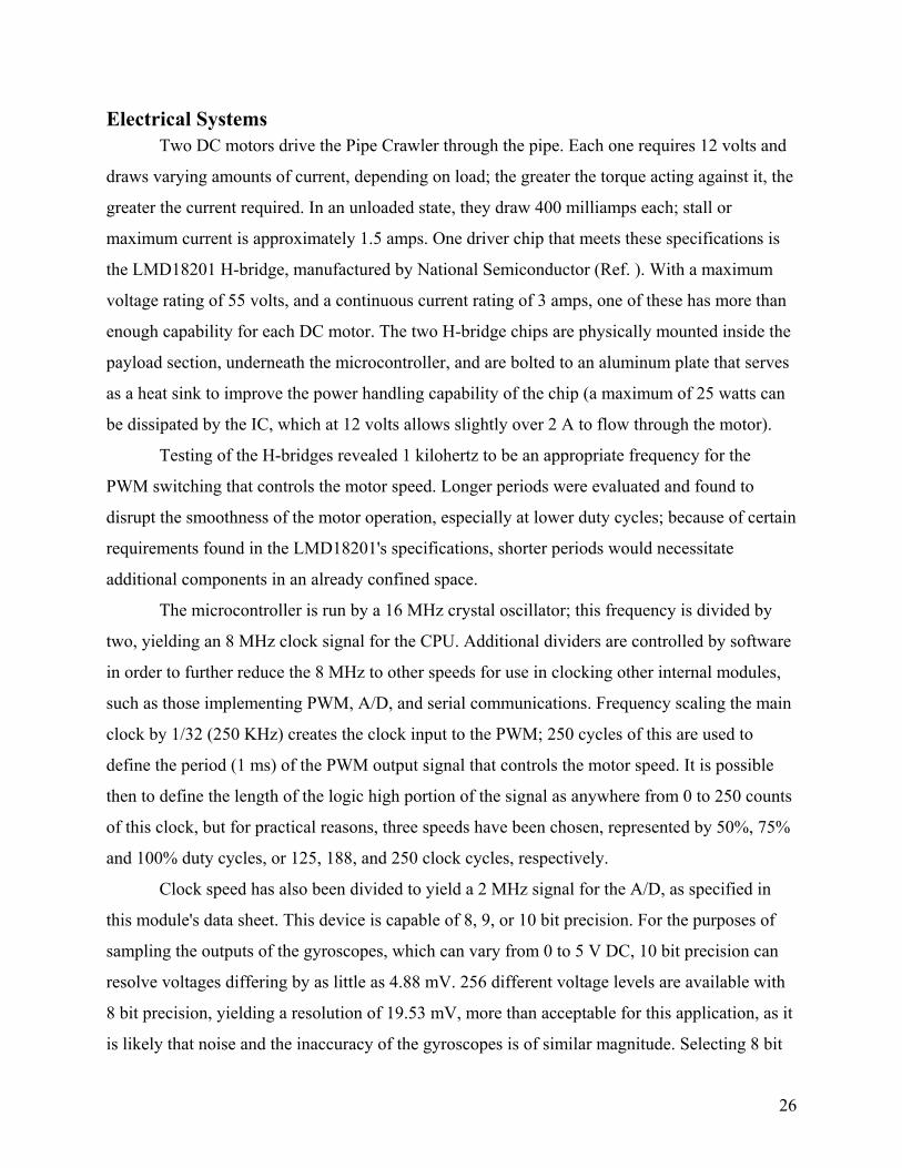
Overview of Final Implementation Some photographs of the final Pipe Crawler will indicate the complexity of this device
when all components, mechanical and electrical, are assembled. Figure 3-11 depicts all seven
segments of the assembled robot, with the tether visible at the left.
Fig. 3-11. Final Pipe Crawler.
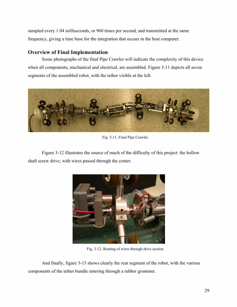
Figure 3-12 illustrates the source of much of the difficulty of this project: the hollow
shaft screw drive, with wires passed through the center.
Fig. 3-12. Routing of wires through drive section.
And finally, figure 3-13 shows clearly the rear segment of the robot, with the various
components of the tether bundle entering through a rubber grommet.
29
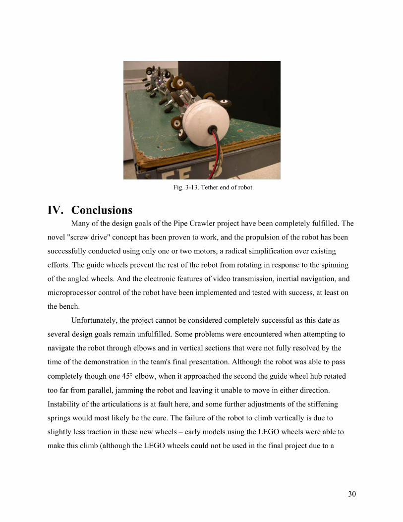
Fig. 3-13. Tether end of robot.
IV. Conclusions Many of the design goals of the Pipe Crawler project have been completely fulfilled. The
novel "screw drive" concept has been proven to work, and the propulsion of the robot has been
successfully conducted using only one or two motors, a radical simplification over existing
efforts. The guide wheels prevent the rest of the robot from rotating in response to the spinning
of the angled wheels. And the electronic features of video transmission, inertial navigation, and
microprocessor control of the robot have been implemented and tested with success, at least on
the bench. Unfortunately, the project cannot be considered completely successful as this date as
several design goals remain unfulfilled. Some problems were encountered when attempting to
navigate the robot through elbows and in vertical sections that were not fully resolved by the
time of the demonstration in the team's final presentation. Although the robot was able to pass
completely though one 45° elbow, when it approached the second the guide wheel hub rotated
too far from parallel, jamming the robot and leaving it unable to move in either direction.
Instability of the articulations is at fault here, and some further adjustments of the stiffening
springs would most likely be the cure. The failure of the robot to climb vertically is due to
slightly less traction in these new wheels – early models using the LEGO wheels were able to
make this climb (although the LEGO wheels could not be used in the final project due to a
30

propensity to slide off of their shaft) – and it is hoped that new wheel springs in the drive section
will yield enough normal force to allow the machine to meet this criterion.
Elbows of 90° remain impassable to the current vehicle. Some experiments will have to
be conducted here; most promising here is the possibility of changing the order of segments, or
removing some of the guide wheels entirely, as it was seen that placing the screw drive first
allowed passage through such elbows (raising the difficulty of housing the video camera, of
course).
The functionality of the electronics, including the inertial navigation units and the
microcontroller with serial communication to a host PC, is best described as partial, as elements
of both were functioning properly prior to the end of the project. Progress on inertial navigation
did reach the stage where all three gyroscopes were being continuously sampled by the
microcontroller, with the results being sent serially to a PC where dials representing each one's
current position were represented on the screen. If one of the gyroscopes were to be rotated by
half a turn, the corresponding dial for that one would, in response, rotate half a turn, etc. Also,
testing of the final microcontroller program in RAM was successful when using the IDE
program environment to communicate the control instructions, but the team did not have time
enough to complete the application program for sending and receiving data to and from the
robot. Unfortunately, certain last-minute difficulties relating to the wiring of the payload section
precluded any demonstration of these successes at the final presentation given by the team.
Further testing of the prototype is necessary for the resolution of some of the minor
design issues preventing the full attainment of the project's initial goals. For example, further
adjustment of the spring joints between sections is needed to prevent the robot from jamming or
buckling. Some of the power regulator boards will have to be repaired. Finally, it would be
desirable to increase the number of electrical connectors between sections, allowing much more
flexibility when wiring the complete robot.
V. Recommendations Aside from repairing the on-board electronics and adjusting the vehicle so that it can
meet all of its mobility goals, which the current team will undertake as a personal project in
coming weeks, several enhancements might be considered by future investigators. For instance,
ultrasonic, eddy current, or other sensors could be mounted on the robot for non-destructive
31

testing of pipe integrity. Another useful feature would be two-axis control over the video camera,
allowing the operator to examine the sides of the pipe closely; even better would be the inclusion
of such a camera in the rear section as well, facilitating backwards travel and providing a view,
possibly, of the robot itself so that mechanical difficulties or other issues can be diagnosed.
Finally, it might be possible to enhance the mobility of the Pipe Crawler so that tee’s and other
fittings can be successfully negotiated – such improvements might consist of servo-motors that
can direct the head and tail sections in order to initiate turns actively.
Perhaps students of energy and dedication can be found to continue this work and
implement some of these ambitious ideas. Certain senior projects have acquired a sort of on-
going status (the Baja car, web-controlled house, and following robot come to mind), some of
them in active development over many years and across numerous versions. It is the hope of the
members of team six that the pipe inspection robot might be among these worthy efforts in the
future.
32

33
References
[1] Robotic Crawlers, Online Internet: http://www.envirosight.com/products/crawlers.html,
2002.
[2] Roboprobe Technologies, Online Internet: http://www.roboprobe.com, 2002.
[3] NC State Engineers Design Pipe-Crawling Robot to Help Save Lives, NC State
University: College of Engineering News. Online Internet:
http://www.engr.ncsu.edu/news/newsletters/pdfs/coenews.spring00.pdf, 2000.
[4] Klassen, Bernhard. Snake 2: A Robot for Difficult Inspection Tasks, Institute for
Autonomous Intelligent Systems, Online Internet:
ftp://set.gmd.de/pub/SET/publications/released/1999/pdf/Klaassen99.1.pdf, 2001.
[5] Single Chip Yaw Rate Gyro with Signal Conditioning, Analog Devices, Inc., Online
Internet:
http://www.analog.com/UploadedFiles/Datasheets/740673780ADXRS150_a.pdf, 2002.
[6] EVBplus Development Board, Online Internet: http://www.evbplus.com, 2003.
[7] Power Supplies, Security Cameras, LCD, Fans, etc., MPJA Online, Online Internet:
http://www.mpja.com/listitems.asp?dept=124&main=123, 2003.
[9] R. Messenger and J. Ventre: Photovoltaic Systems Engineering (CRC Press, Boca Raton,
FL: 2000.
[10] PDL: The Perl Data Language., Online Internet: http://pdl.perl.org, 2001.
[11] MiniIDE Homepage, Online Internet: http://www.mgtek.com, 2002.