the pennsylvania state university structural performance
TRANSCRIPT

The Pennsylvania State University
The Graduate School
Department of Civil and Environmental Engineering
STRUCTURAL PERFORMANCE OF A HYBRID GLASS FIBER REINFORCED
POLYMER BRIDGE DECK SYSTEM
A Thesis in
Civil Engineering
by
Jiejian Zhu
2013 Jiejian Zhu
Submitted in Partial Fulfillment of the Requirements
for the Degree of
Master of Science
August 2013

The thesis of Jiejian Zhu was reviewed and approved* by the following:
Maria Lopez de Murphy Associate Professor of Civil and Environmental Engineering Thesis Advisor
Gordon Warn Assistant Professor of Civil and Environmental Engineering
Charles E. Bakis Distinguished Professor of Engineering Science and Mechanics
Peggy Johnson Professor of Civil and Environmental Engineering Head of the Department of Civil and Environmental Engineering
*Signatures are on file in the Graduate School

iii
ABSTRACT
A lightweight composite bridge deck system was developed as part of a Highway for
LIFE Technology Partnerships Program from the Federal Highway Administration (FHWA). The
deck panel consists of pultruded trapezoidal GFRP tubes and glass fiber outer wrap, and is
designed to be filled with grout if higher stiffness is needed. The performance of tubes and panels
with different grout and grouting patterns was evaluated in single span tests. Also, two-span
flexure tests were performed on grouted and non-grouted panels to evaluate their structural
behavior in both positive and negative bending regions. Test results showed that the epoxy
grouted panel met the AASHTO deflection requirement (L/800) and had promising advantages
over the cementitious grouted panel in terms of flexural stiffness. Different types of potential
failure modes of pultruded tubes were evaluated in order to predict the governing failure mode,
and it was found the predicted failure mode and corresponding failure load matched well with
those from experimental tests. Failure mode of non-grouted panel was found to be preferable
since it was localized failure, which did not lead to collapse. An analytical model was developed
to predict the load-deflection relation of grouted and non-grouted panels in different loading
conditions, and when compared to experimental data, it was able to predict the panel deflection
well even at 3 times the service load within 11.1% error.

iv
TABLE OF CONTENTS
List of Figures ............................................................................................................................... vi
List of Tables ................................................................................................................................ viii
Acknowledgements....................................................................................................................... ix
Chapter 1 INTRODUCTION ....................................................................................................... 1
1.1 Objective ......................................................................................................................... 3 1.2 Research Tasks ............................................................................................................... 3
Chapter 2 LITERATURE REVIEW ........................................................................................... 5
2.1 FRP Pultruded Shapes .................................................................................................... 5 2.1.1 Lateral-torsional Buckling .................................................................................. 5 2.1.2 Local Buckling of Flanges and Webs due to In-plane Compression ............... 6
2.2 All-FRP Bridge Deck ..................................................................................................... 8 2.2.1 Outer wrap: .......................................................................................................... 10
2.3 Hybrid Bridge System .................................................................................................... 12
Chapter 3 EXPERIMENTAL PROGRAM ................................................................................. 15
3.1 Description of Specimens .............................................................................................. 15 3.2 Single Span Flexure Test of Pultruded tubes ................................................................ 17
3.2.1 Test Setup ............................................................................................................ 17 3.2.2 Results and Discussion ....................................................................................... 20
3.3 Single Span Flexure Test of Panels ............................................................................... 26 3.3.1 Test Setup ............................................................................................................ 26 3.3.2 Results and Discussion ....................................................................................... 29
3.4 Two-span Flexure Test of Panels .................................................................................. 32 3.4.1 Test Setup ............................................................................................................ 33 3.4.2 Results and Discussion ....................................................................................... 35
Chapter 4 ANALYTICAL PROGRAM ...................................................................................... 41
4.1 Calculation of 푬푰 and 훋퐆퐀 ........................................................................................... 42 4.2 Failure Analysis of Pultruded Tubes ............................................................................. 47
4.1.1 Non-grouted Tubes ............................................................................................. 47 4.1.2 Grouted Tubes ..................................................................................................... 48
4.3 Timoshenko Beam Theory in Different Loading Conditions ...................................... 50 4.4 Comparison of Analytical Model with Experimental Data ......................................... 54
Chapter 5 CONCLUSIONS AND RECOMMENDATIONS .................................................... 57
5.1 Conclusions ..................................................................................................................... 57

v
5.2 Recommendations for Future Work .............................................................................. 59
References ..................................................................................................................................... 61
Appendix A Calculations ............................................................................................................ 65
A.1 Calculation of 푬푰 and 훋퐆퐀 .......................................................................................... 65 A.2 Calculation of failure load of pultruded tubes ............................................................. 67
A.2.1 Non-grouted Tube .............................................................................................. 67 A.2.2 Grouted Tube ...................................................................................................... 69
A.3 Calculation Related to Timoshenko Beam Theory ..................................................... 72
Appendix B MATLAB Program ................................................................................................ 79
Appendix C Material Information .............................................................................................. 90

vi
LIST OF FIGURES
Figure 2.1. Third generation bridge deck [26] ............................................................................ 11
Figure 2.2. Fourth generation bridge deck [27] .......................................................................... 11
Figure 2.3. Hybrid box beam [6] ................................................................................................. 13
Figure 2.4. Filament wound hybrid box beam [7] ...................................................................... 13
Figure 3.1: Dimensions of pultruded tube and panel (units in inch) ......................................... 16
Figure 3.2: Testing configurations of grouted tube. ................................................................... 18
Figure 3.3: Setup for single span flexure test of pultruded tubes. ............................................. 19
Figure 3.4: Location of Strain gages for tubes tested to failure ................................................. 20
Figure 3.5: Failure modes of non-grouted tubes ......................................................................... 20
Figure 3.6: Load-deflection curves of tubes tested to failure..................................................... 21
Figure 3.7: Load-strain plot of non-grouted tube tested to failure ............................................ 21
Figure 3.8: Grout slip of cementitious grouted tube #22 ........................................................... 24
Figure 3.9: Load-deflection curves of grouted tubes tested to failure ....................................... 25
Figure 3.10: Photographs of failure modes of grouted tubes ..................................................... 26
Figure 3.11: Testing configurations of grouted panels. .............................................................. 27
Figure 3.12: Setup for single span flexure test............................................................................ 28
Figure 3.13: Locations of strain gages and string potentiometers ............................................. 28
Figure 3.14: Behaviors of panels with and without grout .......................................................... 29
Figure 3.15: Different failure modes of the non-grouted panel ................................................. 31
Figure 3.16: Load-displacement response of the failed non-grouted panel .............................. 32
Figure 3.17: Load-strain response of the failed non-grouted panel ........................................... 32
Figure 3.18: Setup for two-span flexure test ............................................................................... 33
Figure 3.19: Locations of strain gages, string potentiometers and LVDTs for epoxy grouted panel ......................................................................................................................... 34

vii
Figure 3.20: Illustration of DIC interested points ....................................................................... 35
Figure 3.21: Displacements of the panels along the span at service load (21 kips) ................. 36
Figure 3.22: Load mid-span deflection at span 2 for two-span flexure test .............................. 37
Figure 3.23: Deflection of epoxy grouted panel near interior support region .......................... 38
Figure 3.24: Strain variation along the cross section B-B of epoxy grouted panel .................. 39
Figure 3.25: Strain variations on the exterior web at section B-B of epoxy grouted panel ..... 40
Figure 4.1: illustration of flexural rigidity calculation and loading phases .............................. 44
Figure 4.2: Plate element division of the specimens .................................................................. 45
Figure 4.3: Illustration of Timoshenko beam theory .................................................................. 50
Figure 4.4: Simplification of two-span structure ........................................................................ 51
Figure 4.5: Prediction of mid-span deflection of panels in one-span condition ....................... 54
Figure 4.6: Prediction of deflection of the epoxy grouted panel along the span ...................... 55
Figure 4.7: Prediction of mid-span deflection of panels in two span condition ....................... 56
Figure A.1: Plate elements division of the non-grouted tube .................................................... 65

viii
LIST OF TABLES
Table 3.1: Testing information of the tubes ................................................................................ 18
Table 3.2: Testing result of grouted tubes ................................................................................... 23
Table 3.3: Testing information of the tubes ................................................................................ 24
Table 3.4: Testing information of the panels .............................................................................. 27
Table 4.1: Engineering properties of different laminates and epoxy grout ............................... 42
Table 4.2: Effective flexural rigidity of specimens .................................................................... 46
Table 4.3: Critical stress and load of non-grouted tube for different failure mode .................. 48
Table 4.4: Critical stress and load of grouted tubes.................................................................... 49
Table A.1: Dimensions of the plate elements ............................................................................. 65
Table A.2: Laminate properties of the tube flange and web ...................................................... 65
Table C.1. Ply details for flanges of the pultruded tube ............................................................. 91
Table C.2. Ply details for webs of the pultruded tube ................................................................ 91

ix
ACKNOWLEDGEMENTS
The author thanks the Bridge Composite Inc. for its support of the research activity in this
study. Moreover, many thanks are due to Dr. Maria Lopez de Murphy, the advisor for this
research project, the thesis committee members – Dr. Gordon Warn and Dr. Charles E. Bakis.

Chapter 1
INTRODUCTION
According to the data from Federal Highway Administration in 2009, almost 22% of
nation’s 603,310 bridges are either structurally deficient or functionally obsolete [1]. This is due
to accumulated degradation of conventional materials used in bridge structures, such as steel and
concrete. Steel is known to be susceptible to corrosion while concrete could crack and spall due
to substandard loading or freeze-thaw process. Thus, it is necessary to build or replace bridge
systems, especially bridge decks, with durable materials and new structure systems. FRP
composites are competitive materials in solving the problems on existing bridges due to their
superior material properties such as low weight, corrosion immunity, and high fatigue strength. In
the last few decades, structural applications of FRP composites started to appear in civil
infrastructure systems, such as FRP sheet for bonded reinforcement, FRP tendon for internal
reinforcement and FRP pultruded shapes for highway structures. Among the new applications of
FRP composites in highway structures, bridge decks for rehabilitation and new construction have
drawn most attention because of their inherent advantages in strength and stiffness per unit
weight as compared to traditional steel reinforced concrete deck [2].
Various all-FRP deck systems have been developed and implemented in USA and
Canada, such as Hardcore system, EZSpan system, Superdeck system and DuraSpan system.
These all-FRP deck systems can be classified into two major categories according to their
construction - sandwich and adhesively bonded pultruded shapes [2]. Sandwich decks provide
design flexibility for deck depth and face sheet, while decks assembled by adhesively bonded
pultruded shapes could achieve good quality control in the factory and optimized design of cross

2
section. In addition, the typical weight of all-FRP bridge deck is only about 20% percent of
conventional concrete bridge deck [3], which facilitates the transportation and installation.
Despite the advantages of all-FRP bridge deck systems, they are still too expensive to
compete with conventional materials. Bakis et al. [2] indicated that the cost of a FRP deck in unit
of per square feet is more than twice the cost of a deck made of conventional materials. Karbhari
and Cheng [4] also indicated that the design of all-FRP bridge deck is driven by stiffness after
reviewing FRP bridges from 1980 to 2006. In order to reduce the cost and enhance the
performance of FRP bridge system, hybrid bridge system combining FRP composites with
components made of traditional materials, such as concrete, was developed. The hybrid concept
was first brought up by Bakeri and Sunder [5], with the idea that the compressive force is carried
by the concrete at the top and the tensile force is taken by FRP at the bottom. Many other
researchers have extended hybrid concept to various bridge applications, such as hybrid girders
and decks. Deskovic et al. [6] investigated the short-term behavior of hybrid glass fiber reinforced
plastic (GFRP) box beams with a layer of concrete on top flange and a carbon fiber reinforced
plastic laminate on bottom flange. Chakrabortty et al. [7] conducted tests of beams formed by
wrapping up a GFRP pultruded profile, a CFRP laminate and a concrete block using filament
winding technique. Aref [8, 9] performed various tests and analysis on a hybrid FRP-concrete
bridge superstructure system comprised of a layer of concrete and three trapezoidal GFRP tubes
surrounded by an FRP outer shell. Johnson et al. [10] compared the performance of GFRP bridge
deck system with and without concrete topping through experimental testing.
Among all these application of hybrid concept to bridge decks and girders, concrete was
the major material used at top side of the structure. However, in case when the deck is lying on
multi-girder bridge and subjected to negative bending above interior girders, the concrete would
be vulnerable to tensile crack. Thus, a substitute material to concrete may need to be investigated
to meet the need in such circumstance.

3
1.1 Objective
The primary objective of this study was to experimentally investigate the flexural
behavior of a newly developed hybrid deck system combining the GFRP pultruded tubes with
different grout materials and grouting pattern, and verify the feasibility of such deck panel in
multi-girder bridges. Two types of grout and two grouting patterns were evaluated in terms of
flexural stiffness and failure mode. Experimental tests of grouted and non-grouted deck panels
were performed in single span and two-span conditions to assess the flexural behaviors of the
panels in positive bending and negative bending regions. An analytic model was developed to
predict the load-deflection response of these deck panels with and without grout. In this study, the
behavior of the hybrid system in different loading conditions is discussed and comparisons of the
analytical model and experimental data are presented.
1.2 Research Tasks
In order to achieve the objective, the following tasks were performed:
Task 1: Single span flexural test of pultruded tubes. Tests in elastic range and to
failure were performed on pultruded tubes with and without grout to evaluate the
failure mode and compare the performance of different grout.
Task 2: Single span flexural test of panels. Grouted and non-grouted panels were
tested in single span condition to compare the stiffness increment by using
different grout and grouting pattern.
Task 3: Two-span flexural test of panels. A non-grouted panel and an epoxy
grouted panel were tested in two-span loading condition to evaluate the behavior
of such hybrid panel in both positive and negative bending moment region, and
prove the feasibility of the use of the hybrid deck panel on multi-girder bridges.

4
Task 4: Failure analysis of pultruded tubes. Existing analytical failure
mechanisms were evaluated for this new type of pultruded tubes in order to
predict the governing failure mode as well as the corresponding failure load.
Task 5: Analytical model for predicting load-deflection behavior of panels. An
analytical model based on the transformed section method and Timoshenko’s
beam theory was developed to predict load-deflection relations in single span and
two-span loading conditions.

5
Chapter 2
LITERATURE REVIEW
Various all-FRP and hybrid deck systems have been developed and implemented in the
USA and Canada. The following sections present the state-of-the-art on the use of these bridge
deck systems and associated research developments. Failure mechanisms of pultruded shapes are
also reviewed as background information on the failure mode of the tubes in this study.
2.1 FRP Pultruded Shapes
FRP Pultruded shapes have been widely used in many industries for more than 30 years
[2] and many failure mechanisms have been investigated. In this section, two types of failure
mechanisms of FRP pultruded profiles are reviewed, including lateral-torsional buckling, local
buckling of flange and web in compression.
2.1.1 Lateral-torsional Buckling
Many researchers have experimentally studied lateral-torsional buckling of doubly
symmetric pultruded profiles [11-13]. It is accepted that the well-known equation (Eq. 2.1) [14]
used for isotropic beam sections can be applied to conventional pultruded I-shape profile.
σ = +( )
(Eq. 2.1)
where 퐶 is a coefficient that account for moment variation along the length of the beam,
푆 = 퐼 /푐 is the section modulus about the strong axis, 퐽 is the torsional constant, 퐼 the second
moment about the weak axis, 퐶 the warping constant, 푘 the effective length coefficient for

6
flexural buckling about the weak axis, 푘 an effective length coefficient for torsional buckling of
the section, and 퐿 the unbraced length of the member. To determine the critical lateral-torsional
buckling stress for a closed section, the first term only in Eq. 2.1 can be used [15]. Since few
experimental data are available for pultruded singly symmetric sections, it is recommended to use
equations for isotropic metallic members with substitution of the orthotropic material properties
[16]. However, lateral-torsional buckling is unlikely to govern for a closed cross section such as a
tube since its torsional resistance is much larger than that of an open section.
2.1.2 Local Buckling of Flanges and Webs due to In-plane Compression
GFRP pultruded profiles are susceptible to local buckling especially when the profile has
low in-plane moduli and large slenderness of the plate element (flanges and webs). Bank and Yin
[17] state that when the load increases beyond the elastic buckling load, the profile will typically
fail as a result of separation of the flange from the web because of high transverse tensile stresses,
followed by in-plane buckling of the unsupported web. The critical buckling stress in a plate
element of a profile is a function of the boundary condition on the longitudinal edges. The flange
of wide flange I-shaped profile is more susceptible to buckling than the flange of box section
since it has a free edge. Kollar [18, 19] has conducted research on obtaining closed-form
equations for buckling of various thin-wall sections with orthotropic plate elements, such as I-,
box-, channel-shaped sections. Kollar’s results match well with finite element analysis and test,
and allow the user to determine whether flange buckling or web buckling will control the design
by comparing the slenderness ratios of flange and web of the section. His design equations for a
doubly symmetric box-shaped profile are presented here.

7
First the buckling stresses of flanges and webs are determined with the assumption that
their edges are simply supported. The buckling stress of the flange of a doubly symmetric box-
shaped profile under uniform compressive stress is given as:
(σ ) = 퐷 퐷 +퐷 + 2퐷 (Eq. 2.2)
where, 푡 is the flange thickness, 푏 is the width of the profile (centerline-to-centerline of the
webs).퐷 ,퐷 , 퐷 , and퐷 are the longitudinal, transverse, coupling, and shear flexural rigidities
(the equivalents of 퐸퐼 per unit width). They are given as:
퐷 =( )
(Eq. 2.3)
퐷 =( )
(Eq. 2.4)
퐷 =( )
=( )
(Eq. 2.5)
퐷 = (Eq. 2.6)
where 푡 is the plate thickness, 퐸 and 퐸 are the modulus of elasticity in longitudinal and
transverse directions, 휐 and 휐 are the major and minor Poisson’s ratio. The buckling stress of
the web of a doubly symmetric box-shaped profile under linearly varying compressive stress is
given as:
(σ ) = 13.9 퐷 퐷 + 11.1퐷 + 22.2퐷 (Eq. 2.7)
where, 푡 is the web thickness and 푑 is the depth of the web. Then whether flanges or webs will
buckle first is determined and the coefficient of edge restraint for the critical wall,휁, is calculated.
The coefficient of restraint is defined to account for the combined effect of the rotational stiffness
of the junction itself and the plate geometric and mechanical properties on the critical buckling
stress, which is given as:
휁 = (Eq. 2.8)

8
where k is the rotational spring constant of the junction between the flange and web, and 퐿 and
D are the width and flexural rigidity of the plate perpendicular to the edge being restrained. The
flange will buckle first if (σ ) /(퐸 ) < (σ ) /(퐸 ) . The spring constant is given as:
푘 = ( ) 1 −( ) ( )( ) ( ) (Eq. 2.9)
The local buckling stress for the rotationally restrained flange is given as:
σ , = 2 (D D ) 1 + 4.139ξ + (D + 2D ) 2 + 0.62ξ (Eq. 2.10)
where
휉 = (Eq. 2.11)
If (σ ) (퐸 )⁄ > (σ ) /(퐸 ) , the webs will buckle first. The corresponding
equations to predict web buckling stress is currently unavailable. It is suggested [20] that Eq. 2.7
can be used as a conservative approximation. However, flange will usually buckle before the
webs for conventional pultruded GFRP box profiles expect for those with large depth-to-width
ratio.
2.2 All-FRP Bridge Deck
Many theoretical and experimental investigations have been conducted to study stiffness,
stability characteristics, and failure modes of all-FRP composite bridge deck systems.
Qiao et al. [21] provided systematic analysis and design approach for a FRP square tube
bonded deck/stringer bridge system. In this study, micro/macromechanics were applied in
sequence to obtain ply properties and panel mechanical properties; then beam or stringer was
analyzed using mechanics of laminated beam theory, followed by deck analysis using elastic
equivalence model; finally combined deck/stringer system was further analyzed by series

9
approximation technique. Design equations were obtained by an approximate series solution for
orthotropic plates including first-order shear deformation. An actual deck was also tested and
finite element modal of the deck was analyzed to correlate with the results from an approximate
series solution. It was concluded that the presented design analysis approach can be efficiently
used to design bridge systems as well as develop new design concepts for similar bridge system.
Alagusundaramoorthy et al. [22] evaluated the behaviors of four different types of FRP
composite bridge deck panels under service load (AASHTO MS 22.5 truck wheel load), factored
load, and cyclic load. Failure modes were also reported. Superdeck system was found to fail by
debonding and punching; hybrid deck system was appeared to fail by flexure-shear; two
sandwich deck systems made by Hardcore Composite and Infrastructure Composites International
failed by web buckling and debonding of face plate.
In 2008, Robinson et al [23] developed and tested five different FRP webbed core deck
panels for extreme application for military use. Carbon fiber and EPON 862 epoxy were used in
order to achieve high strength to weight ratio and better performance under extreme loading and
temperature conditions. In shear test, interlaminar shear failure between the core and skins and
shear failure at the corner between the webs and the skins were found to be dominant failure
modes. Shear failure analysis was presented and it is believed that shear strength could be
increased by modifying manufacturing process of wrapping fabric around four surfaces of the
core beams. In compression test, failure modes of crushing or buckling of the webs were
observed.
Wu et al. [24] conducted compression and flexural tests on non-prestressed and
prestressed tubular bridge deck consist of several pultruded FRP square tubes. Longer span decks
were found to fail by bending while shorter span decks failed by local shear at the tube corner. It
is concluded that span length, interface bond and prestress level could influence the failure mode
and capacity of the deck.

10
2.2.1 Outer wrap:
Bridge deck panel that assembled by modular profiles can be enhanced by adding
additional face sheets or by applying filament-wound wrap. However, face sheets could debond
or delaminate easily if they are not applied properly [25, 26]. It was also found that the outer wrap
could enhance the load capacity of the decks by eliminating failure modes at low load level, and
increase the deformability of the decks [25]. Several studies on wrapped decks are reviewed.
Williams et al. [26] and Crocker et al. [27] developed and tested two types of bridge deck
with cross-section similar to EZ Span system . One is denoted as third generation deck (Figure
2.1), which is filament wound by glass fiber and resin after bonding all the inner tubes together;
the other one is denoted as fourth generation deck (Figure 2.2), which has two face plates bonded
to the surface of inner tubes. The inner tubes are manufactured by filament winding process and
bonded by epoxy resin. Pultruded GFRP bars are used to fill the gap between two tubes. The third
generation deck was subjected to two million cycles under a load varying between 10% and 135%
of the HS30 wheel load at a frequency of 0.5 to 0.9 Hz, and then tested to failure. Results showed
that stiffness degradation after two million cycles was under 5% and the failure mode was
delamination between two of the middle triangular tubes under the load. The fourth generation
deck was failed under similar load level due to delamination that leads to buckling and followed
by punching around loading plate. Williams et al. [26] also applied Classical Laminate Theory
(CLT) to predict the load-deflection behavior of decks shown in Figure 2.2 within elastic range,
and it turned out that CLT could satisfactorily predict the deck stiffness.

11
Figure 2.1. Third generation bridge deck [26] Figure 2.2. Fourth generation bridge deck [27]
Feng et al. [25] tested three types of FRP bridge deck systems, with and without filament-
wound wrap, to study the reinforcing mechanism of filament-wound wrap. For the first type of
deck system assembled by bonded pultruded profiles, adding 2.2 mm thick filament-wound wrap
resulted in 59% increase of ultimate capacity and 12.7% increase in stiffness, and the failure
mode was changed from delamination and buckling of top flange to crack of the inner web. For
the second type of deck system made by pultruded GFRP profiles and lay-up face plates, the
deformability of the deck was more than doubled and had a ductile failure behavior after
filament-wound with 2.2 mm outer wrap, and the failure mode was shifted from debonding
between assembled profile and bottom plate to web crack under loading patch. For the third type
of deck system composed of four filament-wound square tubes bonded with epoxy and two
pultruded GFRP face plates, load capacity had a 26% increase after filament-wound with 3 mm
thick wrap and the failure mode was changed from debonding between tubes and bottom plate to
punching failure under load position. It was concluded filament-wound wrap could improve the
load carrying capacity and failure ductility of FRP deck by eliminating failure mode
corresponding to lower loading capacity.

12
2.3 Hybrid Bridge System
Despite all the advantages of FRP composites, they are still too expensive to compete
with conventional materials. Thus, investigation of combining FRP composites with conventional
materials such as concrete becomes popular recently. Hybrid bridge system can not only enhance
the stiffness and load carrying capacity of the bridge, but also save the initial cost by using the
materials efficiently.
Many researchers have investigated composite girders, also refers to as hybrid girder, in
which compression stresses are majorly carried by thin layer of concrete with high compressive
strength and tension stresses are taken by FRP flange at bottom, results in cost-effective
composite member with high stiffness and strength characteristics while maintaining a low
weight. Some researchers made a step further on designing hybrid girders by adding a CFRP
laminate at the bottom of the girder to increase the stiffness.
In 1995, Deskovic et al. [6] investigate the short-term behavior of hybrid glass fiber
reinforced plastic (GFRP) box beams with a layer of concrete on top flange and a carbon fiber
reinforced plastic laminate on bottom flange (Figure 2.3). A thorough analysis for hybrid
members using the analytical method was given for preliminary design, considering stiffness,
flexural strength, web shear failure by either crushing or buckling, lateral instability, and ductility
design requirements. Also, large-scale bending tests were conducted and finite-element technique
was applied to verify the analytical results. The failure mode of such a hybrid girder was initiated
by tensile rupture of CFRP, giving enough warning of imminent collapse, followed by concrete
crushing. It was concluded that the analytical results matched well with testing data and finite-
element modal and beam behavior could be predicted. They also suggested that ideal bond should
be achieved by combination of adhesives and mechanical connectors.

13
In 2011, Chakrabortty et al. [7] conducted tests of beams formed by wrapping up a GFRP
pultruded profile, a CFRP laminate and a concrete block using filament winding technique
(Figure 2.4). The CFRP is innovatively designed only to increase the stiffness of GFRP profile in
this case without serving as a warning of imminent failure. Thus high stiffness could be achieved
with enough CFRP laminate. Deflection, lateral stability, web buckling load, and flexural
capacity were calculated to satisfy design load. Failure mode was found first through the
debonding of the wrapping followed by the crushing of the concrete block. It was concluded that
the wrapping could not only enhance the stiffness and load carrying ability of the beams, but also
eliminate premature debonding failure of the concrete.
Figure 2.3. Hybrid box beam [6] Figure 2.4. Filament wound hybrid box beam [7]
Some hybrid bridge deck systems have also been developed.
Aref [8, 9] performed detailed tests and analyzed on a hybrid FRP-concrete bridge
superstructure system comprised of a layer of concrete and three trapezoidal GFRP tubes
surrounded by an FRP outer shell. It was found that simple analytical methods such as beam
analysis and orthotropic plate analysis can accurately predict the overall behavior of the hybrid
bridge deck modal with only 1% difference when compared to the experimental data. Detailed
linear and nonlinear finite element analysis was also performed to predict global behavior as well

14
as local damage of the bridge deck panel. In flexural test, it was found that the present of concrete
increased the panel stiffness by 35% and the failure was initiated by concrete crushing followed
by the compressive failure of GFRP flange of outer and inner tube.
Johnson et al. [10] compared the performance of GFRP bridge deck system with and
without concrete topping. The deck panel was made by 3-D woven technology and has balsa
wood cores. Panel without concrete topping has only 50% stiffness and weight of the hybrid
panels. It was found the failure mode for deck panel without concrete was crushing of the top
GFRP skin and the failure mode for deck panel with concrete topping was concrete delamination
followed by failure of shear connectors. Beam analysis and transformed section analysis were
applied to predict the global behavior of both types of deck panels. Results showed both theories
work for longer span (7 feet), but the percent difference between predicted value and
experimental value was doubled when predicting behavior of short span (4 feet).

15
Chapter 3
EXPERIMENTAL PROGRAM
The objective of the experimental program is to evaluate the flexural behavior of
individual tubes and panels with and without grout. The basic element of a panel – pultruded tube
– was tested in three-point bending condition in single span to evaluate the failure mode and
compare the performance of tubes with different grout. Grouted and non-grouted panels
consisting of seven tubes bonded together and wrapped using an outer larger GFRP were tested in
single span condition to assess the flexural behavior in positive flexure and compare the grout and
grouting patterns in terms of flexural stiffness. Last, two-span flexure tests on non-grouted panel
and epoxy grouted panel were conducted to simulate multi-girder bridge condition and assess the
behavior of epoxy grouted panel in both positive and negative bending regions.
3.1 Description of Specimens
An innovative FRP bridge deck system was developed as part of a Highways for LIFE
Technology Partnerships Program, sponsored by the Federal Highway Administration. The deck
was intended for movable bridges with supporting stringers spaced up to 5 feet. The design was
based on a deck system developed by a research team at the University at Buffalo [8].
Improvements have been made in cross section design, material used, and fabrication process in
order to enhance the deck performance and reduce the cost [28].
The basic component of the deck panel – tubes, are produced by a pultrusion process. A
fire-resistant vinyl ester resin was used as matrix [28]. The reinforcement is E-glass rovings,

16
woven mat, and chapped strand mat. The detailed fiber layers for flanges and webs of the
pultruded tube can be found in Appendix C. The dimensions of the tube cross section is shown in
Figure 3.1 (a). The thickness of all flanges of the tube is 0.2 in. and the thickness of webs is 0.24
in.
(a) tube
(b) panel
Figure 3.1: Dimensions of pultruded tube and panel (units in inch)
To fabricate an FRP deck panel, seven pultruded tubes are glued together using epoxy
glue and then wrapped with additional glass fiber fabrics. Vacuum-assisted resin transfer molding
(VARTM) method is then applied to create deck panel with outer wrap. The glass fiber fabrics in
the outer wrap consist of two layers of stitch-bonded biaxial fabric, with a layer of biaxial fabric
between the two layers. Then the three layers are stitched to a layer of continuous filament mat
(randomly oriented fiber). The fabrics are designed specifically for resin infusion processes with

17
the continuous filament mat providing a medium to improve resin flow into reinforcement fiber
during fabrication. The dimension of the cross section of a panel is shown in Figure 3.1 (b).
Top cell or bottom cell of the tube is designed to be filled with grout to enhance the
stiffness. Two types of grout were used in this study, non-shrink cement based grout and epoxy
based grout. They will be referred to as cementitious grout and epoxy grout respectively in the
following discussion. Tubes were casted with grout before gluing together and applying the outer
wrap. The non-grouted panel weighs approximately 20 psf with wearing surface while the
grouted panel weighs about 30 psf with wearing surface, which are much lighter than
conventional bridge decks made of steel or concrete (about 100 psf).
The pultruded tubes were fabricated by Creative Pultrusion Inc. and then assembled by
XCA to create panels. A total of 16 grouted tubes, 10 non-grouted tubes, 8 grouted panels and 4
non-grouted panels were delievered to Civil Infrastructure Testing and Evaluation Laboratory
(CITEL) of Penn State University. All the tubes and panels have the same length of 132 in.
3.2 Single Span Flexure Test of Pultruded tubes
3.2.1 Test Setup
For grouted tube flexure test, two types of grout, cementitious grout and epoxy grout, and
four testing configurations, in which grout could be in either wide cell or narrow cell and
subjected to either tension or compression, were used, as shown in Figure 3.2. “WSU” indicates
Wide Side Up testing position and “WSD” indicates Wide Side Down testing position.

18
(a) wide cell -WSU (b) wide cell-WSD (c) narrow cell-WSD (d) narrow cell-WSU
Figure 3.2: Testing configurations of grouted tube.
A total of ten (10) non-grouted tubes and fifteen (15) grouted tubes were tested in elastic
range to evaluate the stiffness variation of pultruded tubes with and without grout. Two of the
non-grouted tubes and four of grouted tubes were tested to failure to evaluate the failure modes.
Table 3.1 shows the testing information of all the tubes.
Table 3.1: Testing information of the tubes
Tube ID No. Grout type Grouting position Cross-section
position
Loading sequence (kips)
Cyclic load Load to failure
#1 none NA WSU 2.0 #2 none NA WSU 2.5 5 (fail) #3 none NA WSD 2.5 #4 none NA WSU 2.5 #5 none NA WSU 2.5 #6 none NA WSU 2.5 #7 none NA WSD 2.5 #8 none NA WSD 2.5 #9 none NA WSD 2.5 #10 none NA WSU 2.5 4.5 (fail) #11 epoxy Wide cell WSD 3.5 #12 epoxy Wide cell WSU 9.0 (fail) #13 epoxy Wide cell WSU 7.3 #14 epoxy Narrow cell WSD 9.6 (fail) #15 epoxy Narrow cell WSD 7.8 #16 epoxy Narrow cell WSU 3.8 #17 epoxy Narrow cell WSU 1.8 #18 cementitious Wide cell WSU 5.9 #19 cementitious Wide cell WSU 6.4 (fail) #20 cementitious Wide cell WSD 3.8 #21 cementitious Wide cell WSD 1.0 #22 cementitious Narrow cell WSD 7.5 (fail) #23 cementitious Narrow cell WSD 8.0 #24 cementitious Narrow cell WSU 3.8 #25 cementitious Narrow cell WSU 1.0

19
All the FRP tubes were tested under three point loading condition (hydraulic actuator at
midspan). Steel rollers were used for support between a 10 feet span length. Vertical deformation
was measured using one LVDT and/or string pot at mid-span. Two load cells were used to collect
load data (22 kip or 110 kip capacity). The 22 kip load cell was used in nondestructive tests to
better monitor the low-range of load, whereas the 110 kip load cell was used when the tubes were
tested up to failure. A steel plate (12 in. × 4 in. × 0.5 in.) was used under the hydraulic actuator to
create a 4 inch-wide distributed load over the FRP specimen. Figure 3.3 shows the testing setup.
Figure 3.3: Setup for single span flexure test of pultruded tubes.
For non-grouted tubes tested to failure, uniaxial and rosette strain gages were installed at
the locations shown in Figure 3.4.

20
Figure 3.4: Location of Strain gages for tubes tested to failure
3.2.2 Results and Discussion
Testing of ten non-grouted tubes showed consistent stiffness and linear behavior up to 2.5
kip elastic load. The average value of the flexural stiffness (k; calculated as the slope between
300-2,000 lb.) of all the non-grouted tubes is k =1533 lb/inch with a 1.2% variation. The
observed failure modes of the two non-grouted tubes were buckling initiated shear failure and
local failure of GFRP top flange at the edge of loading plate, as shown in Figure 3.5.
Tube #2 (buckling initiated failure) Tube #11 (local failure of top flange)
Figure 3.5: Failure modes of non-grouted tubes
Top flange
Web Web
Top flange

21
Figure 3.6 shows the load-displacement curves of failed non-grouted tubes. Tube #2 has a
linear behavior up to failure while tube #11 shows a nonlinear behavior beyond a load of 4000 lb.
Figure 3.6: Load-deflection curves of tubes tested to failure
Figure 3.7 shows the load-strain plot of the non-grouted tube tested to failure. The strain
gage on the bottom “flange” (SG2) has a quite linear response up to failure load. By contrast,
SG1 near the top flange exhibited a nonlinear response beyond 4,000 lb. of applied load. The
strain gage rossette (SG3-5) displayed a very small magnitude of strain values, as expected.
Recorded strains at the failure load are 0.45% for top flange and 0.77% for bottom flange.
Figure 3.7: Load-strain plot of non-grouted tube tested to failure

22
Table 3.2 shows the testing results of grouted tubes. The flexural stiffness of all the tubes
were calculated in elastic range of load displacement curves (prior to the load when first crack
was noticed). The elastic flexural stiffness of epoxy grouted tubes is found to be 34% larger, on
average, than non-grouted tubes, while the flexural stiffness of cement-based grouted tubes is
only 18% larger than non-grouted tubes. When the cementitious grout is in compression, the
flexural stiffness of the grouted tube is 17% larger than the grouted tube when the cementitious
grout is in tension, which in turn has a very small increment of stiffness over the non-grouted tube.
However, for epoxy grouted tubes, the elastic flexural stiffness has little variation (only 4%)
whether the grout is subjected to compression or tension. Comparing the effect of grouting either
the wide or narrow cell, the epoxy grouted tubes have a 9% larger elastic flexural stiffness when
the narrow cell is filled (as opposed to the wide cell); the cement-based grouted tubes show little
difference.

23
Table 3.2: Testing result of grouted tubes
Tube ID No. Grout type Grouting
position Cross-section
position
Max or failure
Load(kips)
Elastic stiffness (lb/inch)
[load range, lb.]
Load at first crack (kips)
#11 epoxy Wide cell WSD 3.5 1926 [300-2000] 2.55
#12 epoxy Wide cell WSU 9.0(fail) 1920 [300-2000] No crack
#13 epoxy Wide cell WSU 7.3 1993 [300-2000] No crack
#14 epoxy Narrow cell WSD 9.6(fail) 2234 [300-2000] No crack
#15 epoxy Narrow cell WSD 7.8 2182 [300-2000] No crack
#16 epoxy Narrow cell WSU 3.8 2048 [300-2000] 1.59
#17 epoxy Narrow cell WSU 1.8 2045 [300-1750] 1.75
#18 cementitious Wide cell WSU 5.9 1600 [300-2000] No crack
#19 cementitious Wide cell WSU 6.4(fail) 1970 [300-2000] No crack
#20 cementitious Wide cell WSD 3.8 1728 [30-400] 0.4
#21 cementitious Wide cell WSD 1.0 1687 [30-420] 0.42
#22 cementitious Narrow cell WSD 7.5(fail) 2103 [300-2000] 3
#23 cementitious Narrow cell WSD 8.0 1850 [300-2000] 5.98
#24 cementitious Narrow cell WSU 3.8 1646 [30-300] 0.3
#25 cementitious Narrow cell WSU 1.0 1714 [30-360] 0.36
Table 3.3 shows the grouted tubes whose grout is subjected to tension (Figure 3.2b, d)
and their corresponding load when the first cracking sound was heard. Compare the grouted tubes
with the same grouting position, such as #11 and #20, the load when crack initiated for the epoxy
grout is at least 5 times of that for cementitious grout, which indicates that the epoxy grout is
much less vulnerable to tensile crack than cementitious grout.
24
Table 3.3: Testing information of the tubes
Tube ID No. Grout type Grouting position Cross-section
position Load when crack
initiated (kips)
#11 epoxy Wide cell WSD 2.55 #16 epoxy Narrow cell WSU 1.59 #17 epoxy Narrow cell WSU 1.75 #20 cementitious Wide cell WSD 0.4 #21 cementitious Wide cell WSD 0.42 #24 cementitious Narrow cell WSU 0.3 #25 cementitious Narrow cell WSU 0.36
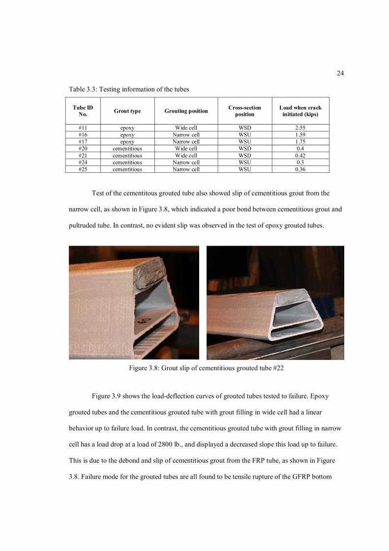
Test of the cementitous grouted tube also showed slip of cementitious grout from the
narrow cell, as shown in Figure 3.8, which indicated a poor bond between cementitious grout and
pultruded tube. In contrast, no evident slip was observed in the test of epoxy grouted tubes.
Figure 3.8: Grout slip of cementitious grouted tube #22
Figure 3.9 shows the load-deflection curves of grouted tubes tested to failure. Epoxy
grouted tubes and the cementitious grouted tube with grout filling in wide cell had a linear
behavior up to failure load. In contrast, the cementitious grouted tube with grout filling in narrow
cell has a load drop at a load of 2800 lb., and displayed a decreased slope this load up to failure.
This is due to the debond and slip of cementitious grout from the FRP tube, as shown in Figure
3.8. Failure mode for the grouted tubes are all found to be tensile rupture of the GFRP bottom

25
flange, regardless of the grout pattern (wide or narrow cell), as shown in Figure 3.10. Cracks
propagate vertically for all specimens, and also horizontally in epoxy grouted tube (Figure 3.10a).
The location of this horizontal crack is at 0.5 in from the bottom, it appears to be at the splice
between the web and the bottom flange of the FRP tube.
Figure 3.9: Load-deflection curves of grouted tubes tested to failure

26
(a) Epoxy grouted tube #12 (b) Epoxy grouted tube #14
(c) Cementitious grouted tube #19 (d) Cementitious grouted tube #22
Figure 3.10: Photographs of failure modes of grouted tubes
3.3 Single Span Flexure Test of Panels
3.3.1 Test Setup
For panel flexure test, two grouting pattern, alternate cell filled pattern and narrow side
cell filled pattern, and four testing configurations were used, as shown in Figure 3.11.

27
(a) Alternate cell filled pattern - WSD (b) Narrow side cell filled pattern - WSD
(c) Alternate cell filled pattern - WSU (d) Narrow side cell filled pattern - WSU
Figure 3.11: Testing configurations of grouted panels.
Four (4) non-grouted panels, four (4) epoxy grouted panels and four (4) cementitious
grouted panels were tested under positive flexure. Non-grouted panels were loaded to 20 kips to
obtain elastic behavior. Grouted panels were first loaded to 20 kips and then to 40 kips to evaluate
the elastic and inelastic performance after the grout cracked. One of the non-grouted panels was
loaded to failure to observe the failure mode. Table 3.4 shows the testing information of all the
panels.
Table 3.4: Testing information of the panels
Panel ID No. Grout type Grouting pattern Cross-section
position
Loading sequence (kN) Single span
Two-span First cycle Second cycle
#1 none NA WSD 89 #2 none NA WSD 89 #3 none NA WSD 89 274 (fail) #4 none NA WSD 89 445 #5 epoxy Narrow side WSD 89 178 #6 epoxy Narrow side WSU 89 178 #7 epoxy Alternate WSU 89 178 #8 epoxy Alternate WSD 89 178 445 #9 cementitious Narrow side WSD 89 178 #10 cementitious Narrow side WSU 89 178 #11 cementitious Alternate WSD 89 178 #12 cementitious Alternate WSU 89 178
Figure 3.12 shows the setup for single span flexural test under three point loading with
hydraulic actuator at mid-span. Steel rollers were used for supports between a 10 feet span length.
A 110 kips load cell was used to collect load data. A steel tube with the dimension of 4 in. × 4 in.
× 3/8 in. was used under the hydraulic actuator to create a 2.75 in. × 35 in. distributed load over

28
the FRP specimen. Strain gages (TSG1, BSG1) and string potentiometers (BD1, BD2, BD3) were
installed to measure the strains and displacements at mid-span on top (T) and bottom (B) surfaces
of the FRP panel, as shown in Figure 3.13. BD1 and BD3 were used to check the deflection
symmetry.
Figure 3.12: Setup for single span flexure test
Figure 3.13: Locations of strain gages and string potentiometers

29
3.3.2 Results and Discussion
Figure 3.14 shows the typical load-deflection behavior of panels with and without grout
up to 20 kips in single span flexure testing condition. “A” stands for grout pattern with alternate
cell filled (Figure 3.11a), and “N” in the bracket stands for grout pattern with narrow side cell
filled (Figure 3.11b). All the panels behaved linearly except for the epoxy grouted panel with
alternate cell filled pattern. Its non-linear response was evident at a load beyond 15 kips. This is
probably due to the crack of epoxy grout under tension at bottom side since the cracking sound
started at this load level. Cementitious grouted panel with alternate cell filled pattern appeared to
behave linearly in the plot because the cementitious grout under tension cracked at very low load.
Figure 3.14: Behaviors of panels with and without grout
Test results showed that the elastic flexural stiffness of the cementitious grouted panels is
only 6.4% higher than that for the panels without grout, regardless of the grout pattern. The
elastic flexural stiffness of the epoxy grouted panels with alternate cells filled pattern is 45%
larger, on average, than the non-grouted panels; the flexural stiffness of the epoxy grouted panels
with narrow side cells filled pattern is 26% larger than non-grouted panels. Thus, epoxy grouted
panels with alternate cell filled pattern are the most efficient with respect to flexural stiffness in
the elastic range.

30
One of the non-grouted panels was loaded to failure in single span testing condition under
displacement control. At the load 61.5 kips and 4.5 in. of deflection, a significant crack noise was
heard and the outer wrap debonded from the inner tubes and buckled outward in the vicinity of
the loading steel tube, as shown in Figure 3.15a. Then the load dropped to 52 kips and multiple
crack sounds were heard, indicating local failure of individual tubes under point load. The panel
is regarded as failure at this point. After retracting the hydraulic actuator, the panel returned to its
original shape with small permanent deformation (0.5 in.), which indicated that the damage area
was localized and the majority of the panel did not suffer damage.
The failed panel was cut into two pieces along the width, close to the damaged region.
Visual inspection of the cut surfaces showed that the outer wrap on top was totally detached from
the inner tubes (Figure 3.15b). The outer wrap at the bottom side was also debonded from the
inner tubes although it was not obviously shown in cut cross section (Figure 3.15b) due to the
non-buckled shape. By contrast, visual inspection couldn’t detect cracks between the individual
FRP tubes. It was also found that the edge tube had delaminaton in both flanges and webs (Figure
3.15c) while the other pultruded tubes remained intact. After removing the detached outer wrap,
the top surface of the FRP tubes was exposed and the compression cracks along the top section of
the FRP tubes were identified (Figure 3.15d).

31
(a) Global failure (b) Debonding of outer wrap
(c) Delamination of edge tube (d) Local damage under loading steel tube
Figure 3.15: Different failure modes of the non-grouted panel
The load-displacement curve of the failed non-grouted panel is shown in Figure 3.16. It
has an overall linear behavior with a little deviation from tangential line after the load of 45 kips.
Figure 3.17 shows the strain data measured in mid-span section. Strain at top surface of the panel
near loading steel tube had quite a linear behavior up to failure load while the strain at bottom
surface behaved nonlinearly after a load of 45 kips, this is a reflection of the debonding of the
outer wrap at the bottom side; it also explained the nonlinear behavior in load-displacement curve
after 45 kips in Figure 3.16. At failure load, the recorded strain at the bottom surface is 8559휇휀,
which is 82% of the ultimate strain obtained from coupon test of the outer wrap [28].

32
Figure 3.16: Load-displacement response of the failed non-grouted panel
Figure 3.17: Load-strain response of the failed non-grouted panel
3.4 Two-span Flexure Test of Panels
Most hybrid FRP bridge deck systems that have been developed to date combine FRP
composites with concrete to increase the stiffness and load carrying capacity of the deck panel.
Yet the concrete is easy to crack under tension, which restricts the use of hybrid FRP-concrete
deck to single span condition where the concrete at top side is subjected to only compression. The
bond between concrete and FRP is also problematic as depicted by Johnson et al. [10].The use of

33
flexible epoxy as grout in this study could be a good solution if the panel is sitting on multi-
girders and subjected to both positive and negative moment since epoxy is a good adhesive to
FRP composites and is not susceptible to tensile crack. The primary objective of the two-span
flexure test is to investigate the behavior of the epoxy grouted panels in negative bending moment
regions.
3.4.1 Test Setup
One non-grouted panel and one epoxy grouted panel with alternate cell filled pattern (see
Table 3.4) were tested in two-span condition. They were loaded to 100 kips due to the 110 kips
capacity of the load cell.
Figure 3.18 shows the setup for the two-span flexure test with two hydraulic actuators
(110 kips capacity in each) at each mid-span. Each span length is 5 feet, which is the maximum
design span length. The shear span/depth ratio for this test is in the order of 6. Half-round steel
beams were used for side supports, and a 3 in. × 3 in. × ¼ in. steel tube was used for interior
support. The loading steel tubes are the same as for the single span flexure test.
Figure 3.18: Setup for two-span flexure test
Strains and displacements at various locations were measured with strain gages, string
potentiometers and LVDTs. Figure 3.19 shows the location of these measuring instruments for

34
epoxy grouted panel. Displacements were measured along the middle of panel width at
longitudinal direction at the locations of mid-span, quarter span and supports. Two LVDTs were
installed at the edge of panel side 5 in. from the interior support (TD3 and TD4) to check the
deformation symmetry while loading. In addition, the Digital Image Correlation (DIC) technique
[32] was also used at this side area to confirm with the displacements measured at TD3 and TD4.
Figure 3.20 shows the side area of the panel where LVDTs and DIC are applied. DIC is able to
capture the field displacements of targeted area by tracking the speckle pattern. For non-grouted
panel, the measuring instruments are the same as those used for epoxy grouted panels expect that
strain gage pairs (top and bottom strain gages) of 2, 3, 5, and 6 were not applied.
Figure 3.19: Locations of strain gages, string potentiometers and LVDTs for epoxy grouted panel

35
Figure 3.20: Illustration of DIC interested points
3.4.2 Results and Discussion
The displacements measured at the supports showed support settlements in the order of
0.07 in. due to the uneven surface of the panel. Thus, the total deflection of the panel was
adjusted to consider these settlement values. The deck panel under study was designed for a
service load of 21 kips, which is the summation of dead load plus HS20 live load with an
additional 30% of the live load to account for impact loading. Figure 3.21 shows the displacement
of the two panels along the span in the longitudinal direction under a service of 21 kips. The load
value denotes the load on each actuator. The measured displacements were quite symmetric with
small variation. The non-grouted panel has about 48% more displacement than epoxy grouted
panel at service load, which shows the efficiency of using epoxy grout.

36
Figure 3.21: Displacements of the panels along the span at service load (21 kips)
Since the specimen tested in this study simulated the use of FRP panels on steel stringers
spaced 5 feet apart (the maximum designed spacing), the deflections of both panels under service
load were compared with the AASHTO deflection limit of L/800 = 0.075 in. (L is the span length
between adjacent supports) as a reference, although the test did not simulate the truck patch load.
For loading, the epoxy grouted panel had a 0.066 in. displacement under service load, which
satisfied AASHTO deflection limit. The non-grouted panel had a 0.098 in. displacement under
service load, which is 30% larger than the deflection limit. Although this value could be
decreased if the truck patch load is applied instead of line load applied in this study, the deflection
of the non-grouted panel is still a concern. In this case, carbon fiber mat could be added into outer
wrap to increase the panel stiffness in the design if casting grout is not preferable due to the
increment of weight.
Figure 3.22 shows the load mid-span displacement curves of non-grouted panel and
epoxy grouted panel up to 80 kips. These curves were obtained from the data of span 2, the non-
grouted panel has a quite linear behavior while the epoxy grouted panel behaved nonlinearly after
the load around 38 kips when cracking sounds were first heard, indicating that the grout started to
crack in tension at this load level. Results show that the epoxy grouted panel performed well in

37
both positive and negative moment regions with a 40% higher initial flexural stiffness than the
non-grouted panel. The estimated cracking load of epoxy grout in tension was 40 kips for
negative moment region and 50 kips for positive moment region in this two-span testing
condition. The slope taken from load-displacement curve of epoxy grouted panel after grout
cracks in both positive and negative moment region (between the load points of 55 kips and 65
kips) was compared with the slope of non-grouted panel, and the result shows the flexural
stiffness of epoxy grouted panel after the grout cracks is still 20% higher than the flexural
stiffness of the non-grouted panel, indicating the effectiveness of the use of epoxy as grout.
Figure 3.22: Load mid-span deflection at span 2 for two-span flexure test
Figure 3.23 shows the displacements of the epoxy grouted panel at the panel side near
interior support region that measured by DIC technique and two LVDTs (located at TD4 and
TD5, see Figure 3.19) at the load of 20 kips. DIC captured the vertical displacement of 11
interested points, as shown in Figure 3.20. The displacements captured by DIC showed a
reasonable agreement with the displacement measured by LVDTs with maximum difference of
13% and also illustrates the support settlement around 0.06 in. at interior support.

38
Figure 3.23: Deflection of epoxy grouted panel near interior support region
Figure 3.24 shows the measured longitudinal strain along the transverse direction (y
direction) of the epoxy grouted panel at the cross section of B-B (Figure 3.19) at different elastic
loads. Positive value denotes the strain gage under tension and negative value denotes the strain
gage under compression. The strains measured at the location of grouted cell are smaller than the
strains at the location of non-grouted cell and tube-to-tube junction. This illustrated that the
presence of the epoxy grout changes the strain variation along the cross section. The strain
measured at the exterior tube, whether at non-grouted cell or grouted cell, showed a larger value
than that of interior tubes by 36% on average. This is due to the edge effect caused by the
presence of outer wrap at exterior webs. The outer wrap makes the exterior tube “stiffer” than
interior tubes, which results in a larger strain when the tubes deform simultaneously.

39
Figure 3.24: Strain variation along the cross section B-B of epoxy grouted panel
Figure 3.25 shows the longitudinal strain variation along the height of the grouted panel
on the exterior web at the cross section of B-B (Figure 3.19). A linear variation of strain along the
height of the panel was observed for a low load of 10 kips. But the strain variation along the
height deviate from linear variation when the load increase, see strain variation at 20 kips in
Figure 3.25. The neutral axis position obtained from these side strain gages at a load of 10 kips is
0.34 × height (from grouted side) of the panel, which is quite close to the neutral axis position of
individual epoxy grouted tube tested before, as illustrated by the dashed line in Figure 3.25. In
contrast, the strain gages on the interior grouted tubes (stain gage pairs of 4, 5 and 6 in Figure
3.19) showed the neutral axis positions to be 0.44 × height (from grouted side) of the panel on
average. The neural axis position of interior tubes is closer to the middle height of the panel due
to the composite behavior between the interior tubes.

40
Figure 3.25: Strain variations on the exterior web at section B-B of epoxy grouted panel

41
Chapter 4
ANALYTICAL PROGRAM
For this newly developed deck panel, an analytical study was performed in order to
predict the performance of such panel (load, deflection and stiffness). A panel tested in a single
span configuration was found to fail by debonding of the outer wrap from the inner tubes. Such
failure mode may due to the shear failure of the adhesive layer [30]. However, initial calculations
in this study indicated that the level of stresses at the bond layer were well below the expected
strength of the bond layer. More bond tests are needed to evaluate this failure mechanism, which
is out of the scope of this study.
For a newly developed bridge deck system, designers usually rely on detailed finite
element analysis (FEA) in its design process. However, FEA is time consuming and not efficient
in initial design phase. In the analytical program presented here, an analytical study based on the
transformed section method and Timoshenko beam theory was performed in order to predict the
load-deflection behavior of the new deck panel. This analytical study, if proved useful, could
serve as a reference and save time in the phase of panel initial design.
Firstly, the failure modes of non-grouted tubes and grouted tubes were analyzed using
existing failure mechanisms and compare to testing data. This step was intended to check if the
existing failure mechanisms applied to this new type of pultruded tube. Then the analytical model
was developed to predict the load-deflection response of non-grouted and epoxy grouted panels in
single span and two span conditions, and compare to experimental data.

42
4.1 Calculation of 푬푰 and 훋퐆퐀
Effective flexural rigidity (퐸퐼) of tubes and panels were calculated using Eq. 4.1-4.2,
and effective shear rigidity (κGA) of panels was calculated using Eq. 4.3. Table 4.1 shows the
engineering properties of laminates used in pultruded tubes, outer wrap and grout. The properties
are obtained from tests conducted in LeTourneau University [28], except that the shear modulus
of webs is obtained indirectly from strain rosette attached to tube web in one-span individual tube
test conducted before.
Table 4.1: Engineering properties of different laminates and epoxy grout Flanges
(t = 0.2”) Webs
(t = 0.24”) Outer wrap (t = 0.15”) Epoxy grout Cementitious
grout modulus in tensionE , 3880 ksi 3430 ksi 2340 ksi 2100 ksi 950 ksi modulus in compressionE , 4160 ksi 4220 ksi 2310 ksi 2100 ksi 950 ksi Shear modulus G NA 1620 ksi NA NA NA Tensile strength σ , 39.95 ksi 32.99 ksi 24.60 ksi 2.5 ksi NA Compressive strength σ , 54.79 ksi 54.10 ksi 36.38 ksi 15 ksi 7.5 ksi Shear strength τ 14.58 ksi 14.77 ksi 9.79 ksi NA NA
The epoxy grouted panel with alternate cell filled pattern would have different effective
flexural rigidity along the length since the epoxy grout would crack during loading. It is assumed
that when epoxy grout subjected to tension stresses reaches to its tensile strength at maximum
moment region, all the epoxy grout in the tension side will stop contributing to effective flexural
rigidity. In other word, flexural rigidity is recalculated after removing the grout in tension. The
flexural rigidity of the uncracked epoxy grouted panel with alternate cell filled pattern is denoted
as(퐸퐼) ; the flexural rigidity after bottom grout (4 cells) cracks is denoted as (퐸퐼) and the
flexural rigidity after top grout (3 cells) cracks is denoted as(퐸퐼) , as shown in Figure 4.1a. For
single span flexure test, the epoxy grouted panel has two loading phases: phase 1 denotes the
uncracked panel and phase 2 denotes the panel with bottom grout cracked. The phase 2 starts at
the load of 14 kip, when the bottom epoxy grout at mid-span reaches to its tensile strength. For

43
two span flexure test, the epoxy grouted panel has three loading phases: phase 1 denotes the
uncracked panel, phase 2 denoted the panel with cracked grout in negative moment region, and
phase 3 denotes the panel with cracked grout in both positive and negative moment region. The
corresponding loads for the initiation of phase 2 and phase 3 are 40 kips and 50 kips. Figure 4.1b
depicts different loading phases for single span and two-span flexure test.

44
a
(퐸퐼) – uncracked
(퐸퐼) – crack at bottom
(퐸퐼) – crack at top
b
Figure 4.1: illustration of flexural rigidity calculation and loading phases
Transformed section method was used to calculate effective flexural rigidity (퐸퐼) of
different panel types and loading phases, in which the flexural rigidity of the cross section is
approximated as the summation of the moment of inertia of each plate element to the neutral axis
(퐸퐼)
(퐸퐼)
(퐸퐼) (퐸퐼) (퐸퐼)
(퐸퐼) (퐸퐼) (퐸퐼)
(퐸퐼)

45
multiplied by the modulus of elasticity of corresponding element. Figure 4.2 illustrates the
element division of the specimens.
Figure 4.2: Plate element division of the specimens
The flexural rigidity can be expressed as:
(퐸퐼) = ∫ 퐸 푧 푑퐴 ≈ ∑퐸 퐴 푧 (Eq. 4.1)
where푖 denotes the element of the panel (flange, web, outer wrap or grout). 퐸 is the modulus of
elasticity of the 푖th element in longitudinal direction. 퐴 is the area of the 푖th element. 푧 is the
distance between the neutral axis of the 푖th element and neutral axis of the panel. The neutral axis
location of the panel, 푧 , can be obtained by
z =∫
∫≈ (Eq. 4.2)
where 푧 is the distance between the neutral axis of the 푖th element and the reference location (in
this case, the top side of the panel cross section). Table 3 shows the calculation results of flexural
rigidity of tubes and panels. Detail calculation can be found in Appendix A.1.

46
Table 4.2: Effective flexural rigidity of specimens Neutral axis location
(measured from wider flange side, inch)
퐄퐈 (kip-in2)
Non-grouted tube 1.918 52095 Epoxy grouted tube (grout in wide cell) 1.546 64482 Epoxy grouted tube (grout in narrow cell) 2.406 68288 Cementitious grouted tube (grout in wide cell) 1.700 59613 Cementitious grouted tube (grout in narrow cell) 2.253 61796 Non-grouted panel 2.352 528600 Epoxy grouted panel (alternate) –(EI) 2.347 709970 Epoxy grouted panel (alternate) – 4 cells cracked,(EI) 2.622 594960 Epoxy grouted panel (alternate) – 3 cells cracked, (EI) 2.139 617430
For conventionally manufactured glass-reinforced box-shape profiles, it has been shown
that the transverse shear rigidity can be approximated by either the full-section shear rigidity or
by the area of the web multiplied by the in-plane shear modulus of the web [31]. For
simplification, the effective shear rigidity(κGA) of the panels in this study is approximated as
the total area of the webs of all the tubes in a panel multiplied by the in-plane shear modulus of
the tube web. The shear modulus of the outer wrap is assumed to be the same as the shear
modulus of the tube web, and the shear properties of the grout is neglected. Then the effective
shear rigidity becomes
(κGA) ≈ κG A cosθ (Eq. 4.3)
where 퐺 is the shear modulus of the tube web, 퐴 is the total area of tubes webs in a panel, 휃 is
the inclination angle of the web (Figure 3.1). The result of the effective shear rigidity is 25233
ksi-in2.
47
4.2 Failure Analysis of Pultruded Tubes
4.1.1 Non-grouted Tubes
In a pultruded tube with trapezoidal cross section and inner flanges, lateral-torsional
buckling, web shear buckling, and web transverse buckling are unlikely to happen. The failure
modes of pultruded trapezoidal tube checked here are flange and web buckling, flange
compressive failure, flange tensile failure, web transverse crushing, and web shear failure. The
failure loads under these failure modes will be calculated and compare with failure load from
experiment, which is 푃 =4.75 kips on average. The detailed calculation can be found in
Appendix A.2.1.
Flange and web buckling: flange buckling and web buckling are examined using Eq.
2.2-2.11 from references. Flange will buckle first with the buckling stress of 11.7 ksi.
Flange compressive failure: the top flange will fail by compression if the flange
buckling is avoided and compressive strength is reached. In this case, compressive strength of the
top flange in longitudinal direction is σ , =54.79 ksi.
Flange tensile failure: the bottom flange will fail by tension if the tensile strength is
reached, which is σ , =39.95 ksi.
Web transverse crushing: web transverse crushing may occur due to concentrated load
under loading plates or at support. It is assumed that web can fail by local crushing if the
crushing stress reach to the transverse compressive strength of the web, which is σ , =37.49.
Critical crushing load is calculated as:
P = σ A = σ , A (Eq. 4.1)
where A is the effective bearing area of the web depending on the web thickness and the width
of the bearing plate.

48
Web shear failure: webs may fail by shear if the shear strength is reached. Critical shear
force is calculated as:
V = τ (Eq. 4.2)
In sum, all the critical stresses of various failure modes are summarized in Table 4.3.
Relative critical load P in 3 point loading condition with 120 inch span is also presented. The
predicted failure loads are divided by experimental failure load for comparison to find governing
failure mode.
Table 4.3: Critical stress and load of non-grouted tube for different failure mode
Failure modes Critical stress (ksi) Critical load Pcr (kip) Pcr /Pexp Flange buckling 20.1 4.38 0.92 Flange compressive failure 54.79 11.9 2.54 Flange tensile failure 39.95 6.98 1.47 Web transverse crushing 37.49 72 15.2 Web shear failure 14.77 23.34 4.91
From Table 4.3, it can be drawn that flange buckling is most likely to be the failure mode
of non-grouted tube, followed by flange tensile failure. Other failure modes seem unlikely to
happen. The failure mechanism of flange or web buckling developed by Kollar [18, 19] applied
well on the pultruded tube in this study with conservative estimation of critical buckling load by
8%.
4.1.2 Grouted Tubes
For grouted tubes, only flange compressive failiure and flange tensile failure were
examined because other failure modes were unlikely to happen due to the presence of grout. All
the grouted tubes tested to failure had the testing position in which the grout is subjected to
compression. It is assumed that no crack occurs during the testing and the grouted tube has a

49
linear behavior up to failure. Table 4.4 shows the estimated failure loads, and the comparison of
estimated failure load with the experimental failure load. Detailed calculation can be found in
Appendix A.2.2.
Table 4.4: Critical stress and load of grouted tubes
Failure modes Tube type Critical stress (ksi)
Critical load Pcr (kip) Pcr /Pexp
flange compressive failure
Epoxy grouted tube (wide cell-WSU) 54.79 18.3 2.03
Epoxy grouted tube (narrow cell-WSD) 54.79 14.5 1.51
Cementitious grouted tube (wide cell-WSU) 54.79 15.4 1.47
Cementitious grouted tube (narrow cell-WSD) 54.79 12.2 2.4
Flange tensile failure
Epoxy grouted tube (wide cell-WSU) 39.95 7.54 0.84
Epoxy grouted tube (narrow cell-WSD) 39.95 9.74 1.01
Cementitious grouted tube (wide cell-WSU) 39.95 7.36 1.15
Cementitious grouted tube (narrow cell-WSD) 39.95 9.42 1.26
Table 4.4 shows that the flange tensile failure is more likely to be the governing failure
mode, which correlates with the experimental observation. For epoxy grouted tube, the
assumption of linear behavior up to failure applied well to the one with grout filling in narrow
cell and the predicted failure load has only 1% difference from experimental failure load. For
epoxy grouted tube with grout filling in narrow cell, the estimation of failure load is conservative.
In contrast, the failure load of cementitious grouted tube obtained from test is lower than the
estimated failure load. This may due to the debond or crack of cementitious grout during test,
which results in a decrease of effective flexural rigidity of the cross section and lead to premature
failure.

50
4.3 Timoshenko Beam Theory in Different Loading Conditions
Timoshenko beam theory has been widely used to determine the deflection of composite
members in bending since it considers the shear deformation of the member. The basic
differential equations are:
= (Eq. 4.3)
−휙 = − (Eq. 4.4)
where 휙 is the slope of the elastic curve due to bending only, z is the transverse deflection due to
bending and shearing, 푥 is the longitudinal direction of the panel, as illustrated in Figure 4.3.
Figure 4.3: Illustration of Timoshenko beam theory
For single span loading condition, the structure is statically determinate and the
maximum mid-span deflection for three-point bending can be obtained by simply solving Eq. 4.3
and 4.4, and is expressed as
z = + (Eq. 4.5)

51
For two-span loading condition, the structure is statically indeterminate and the flexural
rigidity along the span is not constant for epoxy grouted panel due to the crack of grout in
different loading phases. In order to obtain load mid-span deflection relation of the panel in two-
span loading condition, the two-span structure is simplified as one-span pin-fix end beam with the
assumptions that the two spans deform symmetrically and there is no movement of the panel at
the supports, as shown in Figure 4.4. The inflection point located at 8/11 of the span length
separates the effective flexural rigidity along the span in different loading phases. It should be
noticed that for statically indeterminate beams, the redundant force, R , is a function of shear
rigidity and flexural rigidity of the beam, which is different from that for indeterminate beam
when Euler-Bernoulli beam theory is used [20].
Figure 4.4: Simplification of two-span structure
The moment and shear force along the span length are expressed as
M (x) =R x,0 ≤ x ≤
R x− Px+ , ≤ x ≤ L (Eq. 4.6)

52
V (x) =R ,0 ≤ x ≤
R − P, ≤ x ≤ L (Eq. 4.7)
Considering the different loading phase of the panel in two-span loading condition, see
Figure 4.1, the Eq. 4.3 and 4.4 are integrated as following:
휙(푥) =
⎩⎪⎨
⎪⎧ ( ) 푥 + 퐶 ,0 ≤ 푥 ≤
( ) 푥 − 푥 + 푥 + 퐶 , ≤ 푥 ≤ 퐿
( ) 푥 − 푥 + 푥 + 퐶 , 퐿 ≤ 푥 ≤ 퐿
(Eq. 4.8)
푧(푥) =
⎩⎪⎨
⎪⎧ − 푥 +
( )푥 + 퐶 푥 + 퐶 ,0 ≤ 푥 ≤
− 푥 + ( ) 푥 − 푥 + 푥 + 퐶 푥 + 퐶 , ≤ 푥 ≤ 퐿
− 푥 +( )
푥 − 푥 + 푥 + 퐶 푥 + 퐶 , 퐿 ≤ 푥 ≤ 퐿
(Eq. 4.9)
There are seven unknowns, 푅 and 퐶 to 퐶 , and seven boundary conditions and
continuity conditions: 휙(퐿) = 0;휙 = 휙 ;휙 = 휙 ;푧(0) = 0;푧(퐿) =
0;푧 = 푧 ;푧 = 푧 . By substituting these boundary and continuity conditions
into Eq. 4.8 and 4.9, seven unknowns are solved (see Appendix A.3). The redundant force 푅 is
expressed as
푅 = ( ) ( )
( ) ( )
푃 (Eq. 4.10)
Note that if shear deformation is neglected and assume constant flexural rigidity along
the span, the value of the redundant force would be , which is the same as the redundant force
solved using Euler-Bernoulli beam theory. However, shear deformation should not be neglected
in this study since it contributes 10%-15% of the total deformation.
By substituting the value of the solved unknowns into Eq. 4.9, the deflection of epoxy
grouted panel in different loading phases along the span can be obtained:

53
푃ℎ푎푠푒1:푧(푥) = 푃 ×7.435푒(−8)푥3 − 1.8155푒(−4)푥,0 ≤ 푥 ≤
퐿
2
−1.604푒(−7)푥3 + 2.113푒(−5)푥2 − 0.000776푥 + 0.00515,퐿
2≤ 푥 ≤ 퐿
(Eq. 4.11)
푃ℎ푎푠푒2:푧(푥) = 푃 ×
⎩⎨
⎧ 7.646푒(−8)푥3 − 1.879(−4)푥,0 ≤ 푥 ≤퐿
2
−1.583푒(−7)푥3 + 2.113푒(−5)푥2 − 7.823푒(−4)푥 + 0.00515,퐿
2≤ 푥 ≤
8
11퐿
−1.820푒(−7)푥3 + 2.429푒(−5)푥2 − 9.228푒(−4)푥 + 0.00722,8
11퐿 ≤ 푥 ≤ 퐿
(Eq. 4.12)
푃ℎ푎푠푒3:z(x) = 푃 ×
⎩⎨
⎧ 8.785e(−8)x3 − 2.104e(−4)x,0 ≤ x ≤L
2
−1.923e(−7)x3 + 2.521e(−5)x2 − 9.268e(−4)x + 0.00637,L
2≤ x ≤
8
11L
−1.853e(−7)x3 + 2.429e(−5)x2 − 8.868e(−4)푥 + 0.00578,8
11L ≤ x ≤ L
(Eq. 4.13)
Also, the load mid-span deflection relations of the epoxy grouted panel in different
loading phases can be obtained by substituting unknowns and 푥 = into Eq. 4.9:
푃ℎ푎푠푒1:푧 = .( ) + .
= 0.003419푃 (Eq. 4.14)
푃ℎ푎푠푒2:푧 = .( ) − .
( ) + .= 0.00359P (Eq. 4.15)
푃ℎ푎푠푒3:푧 = .( ) − .
( ) + .= 0.00392P (Eq. 4.16)
Following the similar procedure, the load mid-span deflection relations of the non-
grouted panel can be obtained:
푧 = . + . = 0.0044푃 (Eq. 4.17)
Sometimes the redundant force 푅 is taken as for approximation to solve for load mid-
span deflection relation (for the epoxy grouted panel), resulting in
푧 =( )
+ = 0.003144푃 (Eq. 4.18)
Compare Eq. 4.14 with Eq. 4.18, it is found that the deflection calculated using Eq. 4.14
would be 9% larger than the one obtained from Eq. 4.18 in the two-span loading condition. Since
the design of GFRP panels are usually driven by stiffness, approximating the redundant force as
may result in inadequate stiffness in preliminary design.

54
4.4 Comparison of Analytical Model with Experimental Data
In a single span loading condition, the predicted load mid-span deflection relations of
both the non-grouted and epoxy grouted panels can be obtained using Eq. 4.5. Figure 4.5 shows
the comparison of the load mid-span deflection relations between the analytical model and
experimental data in a single span condition. The analytical model for the non-grouted panel has a
linear relation whereas the analytical model for the epoxy grouted panel is a bilinear curve with
the turning point at a load of 14 kips when the flexural rigidity is changed due to the crack of
epoxy grout on bottom side, as shown in Figure 4.1. The maximum deflection difference between
the analytical model and experimental data is only 2% for grouted panel, and 4.5% for non-
grouted panel at the load of failure.
Figure 4.5: Prediction of mid-span deflection of panels in one-span condition
In a two-span loading condition, the deflection of the epoxy grouted panel along the span
in different loading phases is obtained by substituting the load value into Eq. 4.11-13, and
compared to the corresponding experimental data at the same load, as shown in Figure 4.6. In
span 2, the predicted deflection for three loading phases matches well with experimental data
within 11% difference, whereas in span 1, the experimental data shows 20% smaller deflection at

55
mid-span in loading phase 3. The predicted deflection shows larger values than experimental data
due to the neglect of shear properties of epoxy grout in calculating shear rigidity of epoxy grouted
panel.
Figure 4.6: Prediction of deflection of the epoxy grouted panel along the span
The predicted load mid-span deflection relations of both the non-grouted and epoxy
grouted panels can be obtained using Eq. 4.14-4.17. Figure 4.7 shows the comparison of
predicted load mid-span deflection curves with experimental data at span 2. The analytical model
for the non-grouted panel has a linear relation whereas the analytical model for the epoxy grouted
panel is a tri-linear curve with the two turning points at load of 40 kips and 50 kips, when the
flexural rigidity is changed along the span, as illustrated in Figure 4.1. The predicted deflection
for the non-grouted panel matches very well with the experimental data within 1% difference.
The predicted deflection for epoxy grouted panel is slightly larger than the experimental data with

56
the maximum difference of 13%, which is probably due to the neglect of shear properties of
epoxy grout in calculating shear rigidity of epoxy grouted panel as mentioned before.
Figure 4.7: Prediction of mid-span deflection of panels in two span condition
In sum, the analytical model proposed in this study based on transformed section method
and Timoshenko beam theory could accurately predict the deflection behaviors of both non-
grouted panels and epoxy grouted panels in single span and two-span loading conditions.
The accurate prediction also illustrates that no bond problem between epoxy grout and
pultruded tube occurred during the test, which shows the effectiveness of using epoxy grout.

57
Chapter 5
CONCLUSIONS AND RECOMMENDATIONS
This study investigated the flexural behavior of individual tubes and panels of a newly
developed FRP deck system. The effect of the use of different types of grout and grouting
patterns was assessed with respect to the flexural rigidity of specimen (tube and panel). Various
failure modes of pultruded tubes were evaluated and compared to experimental data. An
analytical model was also developed in order to predict the load-deflection behavior of the panels.
5.1 Conclusions
The major conclusions of this study are as follows:
1. The non-grouted tube and the epoxy grouted tube had linear load-deflection behavior up to
failure while the cementitious grouted tube showed nonlinear response due to the crack and
debond of the cementitious grout from the tube.
2. The epoxy grout was a better choice than the cementitious grout. The cementitious grout has a
poor bond effect in the GFRP pultruded tube while the epoxy grout has a better bond
performance in the GFRP pultruded tube. The epoxy grout is much less vulnerable to tensile
crack than cementitious grout since the load when crack initiated for the epoxy grout is more
than 5 times of that for cementitious grout. The epoxy grout increases the tube stiffness by
34%, on average, while the cementitious grout only increases the tube stiffness by 18%.
3. For the epoxy grouted panel, the alternate cell filled pattern was proved to be the most
effective grouting pattern since it increases the panel stiffness by 45%, while the narrow side
cell filled pattern increases the panel stiffness by 26%. The cementitious grout is considered as
poor choice for grouting panel since it only increase the panel stiffness by 6.4%, regardless of

58
the grouting pattern. This is due to the fact that the cementitious grout cracks in tension at
early loading stages.
4. Experimental tests showed that the deck panel combining GFRP composite and epoxy grout
can be used on multi-girder bridges. The epoxy grouted panel performed well in both positive
and negative moment region in multi-span loading condition without any audible crack
initiated at service load. It has 40% higher stiffness than the non-grouted panel. The epoxy
grouted panel exhibited to cracking initiation at a load 2 times the service load.
5. The experimental study showed that the epoxy grouted panel satisfied the AASHTO
deflection limit (L/800) at service load while the non-grouted panel exceeded this deflection
limit by 30%. A potential solution to the inadequate stiffness of the non-grouted panel is to
add stiffness to the outer wrap by including a carbon fiber mat when light weight is needed for
the bridge deck.
6. The Digital Image Correlation (DIC) technique was proved to be a good tool for displacement
measurement since it was able to capture the small displacement with a maximum 13%
difference from the one measured by LVDT.
7. The non-grouted panel that tested in single span flexure failed by debonding of the outer wrap
from the inner tubes. This is a preferable failure mode since it did not lead to panel collapse,
but rather, the buckling of the outer wrap after debonding serves as a warning sign of
imminent failure.
8. The buckling failure mechanism developed by Kollar was proved to successfully predict the
failure of the newly designed pultruded tubes with conservative estimation of the failure load
by 8%.
9. The analytical model based on the transformed section method and Timoshenko beam theory
was able to accurately predict the load-deflection behavior of both non-grouted panel and

59
epoxy grouted panel. Differences between experimental results and predictions are in the order
of 5% for the single span loading condition and 13% for the two-span loading condition.
5.2 Recommendations for Future Work
In two-span flexure test, the non-grouted panel was found to have 30% more
displacement than AASHTO required displacement limit L/800. A potential solution is to add a
carbon fiber mat into the outer wrap to increase the panel stiffness if lightweight of the panel is
needed, since casting grout increase the panel weight by 50% [28]. Additional tests should be
conducted to prove that putting additional carbon fiber mat into the outer wrap could help the
non-grouted panel meet the AASHTO displacement requirement and do not induce new issues
such as delamination.
In this study, only the flexural behavior of the deck panels was assessed. In order to fully
understand the structural performance of such a deck panel in its service life, shear behavior of
the panel should also be investigated. And testing considering the effect of the tire patch load is
needed to simulate the real loading condition in the field. In such case, the Timoshenko beam
theory should be reevaluated considering the effect of tire patch load.
One of the non-grouted panels was subjected to fatigue load up to 1 million cycles. The
load range that applied was 1 kip to 14 kip, and the loading frequency was 1.5 Hz. 14 kip is
considered equivalent to the effect of the design truck (16 kips) times the dynamic allowance
(1.15) times the load factor assuming a finite life check (0.75). The wearing surface was also
applied on the panel surface and subjected to cyclic load. Testing results showed that there was
no stiffness degradation of the non-grouted panel after 1 million cycles fatigue load, and there
was no visible crack or debond in the wearing surface. In order to prove the feasibility of the

60
epoxy grouted panel, fatigue test should also be applied to evaluate the fatigue behavior of the
epoxy grouted panel and confirm that the epoxy grout is not susceptible to cyclic load.
A non-grouted panel was tested to failure in this study and the failure mode was found to
be the debonding of outer wrap from the inner tubes. Ji et al. [29] and Teixeira de Freitas [30]
state that the debonding failure of composite bridge decks is usually caused by shear. However,
preliminary analysis of the panel in this study showed that shear stress at bond layer is so small
that it is unlikely to cause failure. The outer wrap is made by vacuum-assisted resin transfer
molding (VARTM) method, in which a small flaw may results in weak bond. Thus, future
investigation is needed to understand the failure mechanism, which may relate to more
destructive tests of the non-grouted panels and grouted panels.
In order to apply the deck panel in this study to the field, the connection of the panel to
the underlying girders should be investigated. Bolt connection was proposed in the design [28].
The behavior of the bolt and composite action between the panel and the girder under static as
well as cyclic load should be studied. A field test using the real truck, which has been conducted,
is preferable to better understand the reaction of the whole bridge.

61
References
1. Federal Highway Administration and Federal Transit Administration. “2010 Conditions and
Performance Report”, <http://www.fhwa.dot.gov/policy/2010cpr>.
2. Bakis, C.; Bank, L.; Brown, V.; Cosenza, E.; Davalos, J., Lesko; J., Machida, A.; Rizkalla, S.;
and Triantafillou, T. “Fiber-Reinforced Polymer Composites for Construction—State-of-the-
Art Review”. Journal of Composites for Construction, 6(2), 73–87.doi: 10.1061/(ASCE)1090-
0268(2002)6:2(73)
3. Keller, T. “Recent all-composite and hybrid fibre-reinforced polymer bridges and buildings”.
Progress in Structural Engineering and Materials, Volume 3, Issue 2, pages 132–
140, April/June 2011.
4. Cheng, L.; Karbhari, V. M. “New bridge systems using FRP composites and concrete: a state-
of-the-art review”. Progress in Structural Engineering and Materials, v 8, n 4, p 143-54, Oct.-
Dec 2006.
5. Bakeri PA, Sunder SS. “Concepts for hybrid FRP bridge deck systems”, Serviceability and
durability of construction materials. In: Proceedings of first materials engineering congress,
Denver, Colorado, ASCE, vol. 2, p. 1006-15, August 13-15 1990.
6. Deskovic, N.; Triantafillou, T. C.; Meier, U. “Innovative Design of FRP Combined with
Concrete Short-Term Behavior”. Journal of structural engineering, N.Y., v 121, n 7, p 1069-
1078, Jul 1995.
7. Chakrabortty, A.; Khennane, A.; Kayali, O.; Morozov, E. “Performance of outside filament-
wound hybrid FRP-concrete beams”. Composites Part B: Engineering, v 42, n 4, 907-15, June
2011.
8. Aref, A. J.; Kitane, Y.; Lee, G. C. “Analysis of hybrid FRP-concrete multi-cell bridge
superstructure”. Composite Structures, v 69, n 3, p 346-59, July 2005.

62
9. Alnahhal, W.; Aref, A.J. “Structural performance of hybrid fiber reinforced polymer-concrete
bridge superstructure systems”. Composite Structures, v 84, n 4, 319-36, Aug 2008.
10. Johnson, C. M.; Mohamed, T. S.; Rizkalla, S. H. “Behavior of three dimensionally woven
glass fiber reinforced polymeric bridge deck”. Composites, Convention and Trade Show,
American Composites Manufactures Association, St. Louis, MO USA. October 18-20, 2006.
11. Mottram, J. T. “Lateral torsional buckling of a pultruded I beam”. Composites, Vol.23, pp. 81-
92, 1992
12. Turvey, G. J. “Effects of load position on the lateral buckling response of pultruded GRP
cantilevers: comparisons between theory and experiment”. Composite Structures, Vol. 35, pp.
33-47, 1996.
13. Davalos, J. F.; Qiao, P. “Analytical and experimental study of lateral and distortional buckling
of FRP wide-flange beams”. Journal of Composites for Construction, Vol.1, pp.150-159, 1997.
14. Salmon, C. G.; Johnson, J. E. “Steel Structures: Design and Behavior, 4th ed.”. HarperCollins,
New York, 1996.
15. ASCE (1984) “Structural Plastics Design Manual”. ASCE Manuals and Reports on
Engineering Practice 63, American Society of Civil Engineers, Reston, VA.
16. Razzaq, Z.; Prabhakaran, R.; Sirjani, M. M. “Load and resistance factor design (LRFD)
approach for reinforced-plastic channel beam buckling”. Composites: Part B, Vol. 27B, pp.
361-369, 1996.
17. Bank, L. C.; Yin, J. “Analysis of progressive failure of the web-flange junction in the
postbuckled pultruded I-beam”. Journal of Composites for Construction, Vol. 3, pp. 177-184,
1999.
18. Kollar, L. P. “Local buckling of fiber reinforced plastic composite structural members with
open and closed cross sections”. Journal of Structural Engineering, Vol. 129, No. 11, pp.
1503-1513, 2003.

63
19. Kollar, L. P.; Springer, G. S. “Mechanics of Composite Structures”. Cambridge University
Press, Cambridge, 2003.
20. Bank, L. C. “Composite for Construction: Structural Design with FRP Materials”. John Wiley
& Sons, Inc., Hoboken, New Jersey, 2006.
21. Qiao, P.; Davalos, J. F.; Brown, B. “A systematic analysis and design approach for single-span
FRP deck/stringer bridges”. Composites Part B: Engineering, v 31, n 6-7, p 593-609, October
2000.
22. Alagusundaramoorthy, P.; Harik, I.E.; Choo, C.C. “Structural behavior of FRP composite
bridge deck panels”. Journal of Bridge Engineering, v 11, n 4, p 384-393, July/August 2006.
23. Robinson, M.J.; Kosmatka, J.B. “Light-weight fiber-reinforced polymer composite deck
panels for extreme applications”. Journal of Composites for Construction, v 12, n 3, p 344-
354, 2008
24. Wu, ZH; Mirmiran, A.; Zhu, ZY; Swanson, J. “Flexural behavior of prestressed FRP tubular
bridge deck”. Composites: Part B, v 40, p 125-133, 2009
25. Feng, P; Ye, L; Li, T; Ma, Q. “Outside filament-wound reinforcement: A novel configuration
for FRP bridge decks”. The 9th International Symposium on Structure Engineering for Young
Experts/Fuzhou & Xiamen, China, 2006.
26. Williams, B; Shehata, E; Rizkalla, SH. “Filament-wound glass fiber reinforced polymer
bridge deck modules”. Journal of Composites for Construction 2003:7(3): 266–273.
27. Crocker, H.; Mufti, A.; Shehata, E.; Haldane-Wilsone, R. “Innovative fiber reinforced
polymer bridge deck modules”. Presented at the 6th Int. Conf. on Short and Medium Span
Bridges, Vancouver, Canada, August 2002.
28. O’Connor, J. S. “Composite Bridge Decking: Final Project Report”. FHWA-HIF-13-029,
Federal Highway Administration, Washington, D.C., March 2013.

64
29. Ji, HS; Byun, JK; Lee, CS; Son, BJ; Ma, Z. J. “Structural performance of composite sandwich
bridge decks with hybrid GFRP-steel core”. Composite Structure, v 93, n 2, 430-42, Jan. 2011.
30. Teixeira, F. S.; Kolstein, H.; Bijlaard, F. “Composite bonded systems for renovations of
orthotropic steel bridge decks”. Composite Structures, v 92, n 4, p 853-862, March 2010.
31. Bank, L. C. “Flexural and shear moduli of full-section fiber reinforced plastic (FRP) pultruded
beams”. Journal of Testing and Evaluation, Vol. 17, No. 1, pp. 40-45.
32. Shukla, A.; Dally, J. W. “Experimental Solid Mechanics”. College House Enterprises, LLC.,
Knoxville, TN, 2010.
33. Timoshenko, S.P. “On the correction for shear of the differential equation for transverse
vibration of prismatic bars”. Philosophical Magazine, Vol. 41, pp. 744-46, 1921.

65
Appendix A
Calculations
A.1 Calculation of 푬푰 and 훋퐆퐀
The element numbers of non-grouted tube are shown in Figure A.1, and their dimensions are
shown in Table A.1.
Figure A.1: Plate elements division of the non-grouted tube
Table A.1: Dimensions of the plate elements
Element No. 1 2 3 4 5 6 Thickness t, inch 0.2 0.2 0.2 0.2 0.24 0.9 Width b, inch 6.1 5.57 3.94 3.46 4.32 6.0 (5.29)* *the number in bracket denotes the width of the trapezoidal short side
The laminate properties of the tube flange and web are repeated here, as shown in Table A.2.
Table A.2: Laminate properties of the tube flange and web Flanges
(t = 0.2”) Webs
(t = 0.24”) Outer wrap (t = 0.15”) Epoxy grout Cementitious
grout modulus in tensionE , 3.88 msi 3.43 msi 2.34 msi 2.1 msi 0.95 msi modulus in compressionE , 4.16 msi 4.22 msi 2.31 msi 2.1 msi 0.95 msi Shear modulus G NA 1.62 msi NA NA NA

66
Neutral axis positions of tubes and panels are calculated using MATLAB. The MATLAB
program can be found in Appendix B. For illustration purpose, the calculation of neutral axis
position and effective flexural rigidity of non-grouted tubes is exemplified here. Assume the
neutral axis is located x from the wider flange,
x =∫ 퐸 푧 dA
∫ 퐸 dA≈퐸 퐴 푧퐸 퐴
=퐸 (푡 × 푏 )푧 + 퐸 (푡 × 푏 )푧 + 퐸 (푡 × 푏 )푧 + 퐸 (푡 × 푏 )푧 + 퐸 (푡 × 푏 )푧 + 2퐸 , 푡 × 푏 , 푧 , + 2퐸 , 푡 × 푏 , 푧 ,
퐸 (푡 × 푏 ) + 퐸 (푡 × 푏 ) + 퐸 (푡 × 푏 ) + 퐸 (푡 × 푏 ) + 퐸 (푡 × 푏 ) + 2퐸 , 푡 × 푏 , + 2퐸 , 푡 × 푏 , 푧 ,
=
4160 × (0.2 × 6.1) × 0.1 + 4160 × (0.2 × 5.57) × 1.1 + 3880 × (0.2 × 3.94) × 3.28 + 3880 × (0.2 × 3.46) × 4.38
+2× 4220 × (0.266 × 푥) × 푥2 + 0.2 + 2 × 3430 × 0.266 × (4.08 − 푥) × 푥 + (4.08 − 푥)
24160 × (0.2 × 6.1) + 4160 × (0.2 × 5.57) + 3880 × (0.2 × 3.94) + 3880 × (0.2 × 3.46)
+2× 4220 × (0.266 × 푥) + 2× 3430 × 0.266 × (4.08 − 푥)
By solving this equation, the neutral axis position is obtained to be 1.918 in. from wider flange.
Then the effective rigidity is calculated as
(퐸퐼) = 퐸 푧 푑퐴 ≈ 퐸 퐴 푧
= 퐸 (푡 × 푏 )푧 + 퐸 (푡 × 푏 )푧 + 퐸 (푡 × 푏 )푧 + 퐸 (푡 × 푏 )푧 + 퐸 , 푡 × 푏 , 푧 , + 퐸 , 푡 × 푏 , 푧 ,
= 4160 × (0.2 × 6.1) × (1.918 − 0.1) + 4160 × (0.2 × 5.57) × (1.918 − 1.1) + 3880 × (0.2 × 3.94) × (1.918 − 3.28)
+3880 × (0.2 × 3.46) × (1.918 − 4.38) + 2 × 4220 ×0.266 × (1.918 − 0.2)
12+ (0.266 × 1.918) ×
1.918 − 0.22
+2 × 3430 ×0.266 × (4.08 − 1.918)
12+ 0.266 × (4.08 − 1.918) ×
4.08 − 1.9182
= 52095kip-in2
The shear rigidity κGA of the panel is calculated using Eq. 4.3.
(κGA) = κG A sin θ = 1.0 × 1620푘푠푖 × (0.266 × 4.08× 2 × 7 + 0.1615× 4.48× 2) × 푐표푠(20.6 ) = 25233
ksi-in2

67
A.2 Calculation of failure load of pultruded tubes
A.2.1 Non-grouted Tube
Flange or web buckling:
For flanges, longitudinal, transverse, coupling, and shear flexural rigidities were first
calculated. The shear modulus of the tube flange is assumed the same as that of tube web.
D = ( ) =×( . ")
( . × . ) = 2.92 kip-in2
D = ( ) =×( . ")
( . × . ) = 2.00 kip-in2
D = ( ) =. × ×( . ")
( . × . ) = 0.65 kip-in2
D = = ×( . ") = 1.08 kip-in2
Then the buckling stress of the flange of pultruded tube is calculated:
(σ ) = 퐷 퐷 +퐷 + 2퐷 =. "×( . ") √2.92 × 2.0 + 0.65+ 2 × 1.08 = 12.2 ksi
For webs, longitudinal, transverse, coupling, and shear flexural rigidities were also
calculated.
D =( )
= ×( . ")( . × . )
= 5.12 kip-in2
D =( )
= ×( . ")( . × . )
= 4.10 kip-in2
D =( )
= . × ×( . ")( . × . )
= 1.14 kip-in2
D = = ×( . ") = 1.87 kip-in2
Then the buckling stress of the web of pultruded tube is calculated:

68
(σ ) = 13.9 퐷 퐷 + 11.1퐷 + 22.2퐷 =. "×( . ")
13.9√5.12 × 4.1 + 11.1 ×
1.14 + 22.2 × 1.87 = 5975 ksi
The buckling stresses are compared to determine whether the flange or the web will
buckle first.
(휎 )(퐸 ) =
12.2푘푠푖4160푘푠푖
= 0.00293 <(휎 )(퐸 ) =
5975푘푠푖4220푘푠푖
= 1.42
Thus, flange buckling controls. The rotational spring constant of the junction between
flange and web is then determined:
푘 = ( ) 1 −( ) ( )( ) ( ) = × .
. "1 − .
.= 18.2 ksi/in
The coefficient of restraints is:
휁 =퐷푘퐿
=2.00푘푠푖
18.2 × 6.5"= 0.0169
The local buckling stress of the rotationally restrained flange is:
σ , = 2 (D D ) 1 + 4.139ξ + (D + 2D ) 2 + 0.62ξ =
(6.5")2×0.2" 2 (2.92× 2.00)(1 + 4.139 × 0.855) + (0.65 + 2 × 1.08)(2 + 0.62 × (0.855) ) =
20.1ksi
where
휉 = =× .
= 0.855
The corresponding critical load P in 3 point loading condition with 120 inch span is:
σ , = 20.1 =푀퐼× 푧 =
푃퐿/4(퐸퐼)
× 푧 × 퐸 =푃 × 120"/452095
× 1.918" × 4160 = 4.59푃
푃 = 4.38푘푖푝푠
Flange compressive failure:

69
σ , = 54.79 =MI× z =
PL/4(EI)
× z × E =P × 120"/452095
× 1.918" × 4160 = 4.59P
푃 = 11.9kips
Flange tensile failure:
σ , = 39.95 =MI× z =
PL/4(EI)
× z × E =P × 120"/452095
× 2.562" × 3880 = 5.72P
푃 = 6.98kips
Web transverse crushing:
The compressive strength of the web in transverse direction is σ , = 37.49 ksi.
P = σ , A = 37.49 × (2 × 0.24" × 4") = 72 kips
Web shear failure:
V = τ = τ ( )( ) = 14.77 × . " = 11.67 kips
푃 = 2Vcr = 23.34 kips
A.2.2 Grouted Tube
Flange compressive failure:
1. Epoxy grouted tube (wide cell-WSU):
σ , = 54.79 =MI× z =
PL/4(EI)
× z × E =P × 120"/464482
× 1.546" × 4160 = 2.99P
P = 18.3kips
2. Epoxy grouted tube (narrow cell-WSD):

70
σ , = 54.79 =MI× z =
PL/4(EI)
× z × E =P × 120"/468288
× 2.074" × 4160 = 3.79P
P = 14.5kips
3. Cementitious grouted tube (wide cell-WSU):
σ , = 54.79 =MI× z =
PL/4(EI)
× z × E =P × 120"/459613
× 1.700" × 4160 = 3.56P
P = 15.4kips
4. Cementitious grouted tube (narrow cell-WSD):
σ , = 54.79 =MI× z =
PL/4(EI)
× z × E =P × 120"/461796
× 2.227" × 4160 = 4.5P
P = 12.2kips
Flange tensile failure:
1. Epoxy grouted tube (wide cell-WSU):
σ , = 39.95 =MI × z =
PL/4(EI) × z × E =
P × 120"/464482 × (4.48"− 1.546") × 3880 = 5.30P
P = 7.54kips
2. Epoxy grouted tube (narrow cell-WSD):
σ , = 39.95 =MI × z =
PL/4(EI) × z × E =
P × 120"/468288 × (4.48"− 2.074") × 3880 = 4.10P
P = 9.74kips
3. Cementitious grouted tube (wide cell-WSU):
σ , = 39.95 =MI × z =
PL/4(EI) × z × E =
P × 120"/459613 × (4.48"− 1.700") × 3880 = 5.43P
P = 7.36kips
4. Cementitious grouted tube (narrow cell-WSD):

71
σ , = 39.95 =MI× z =
PL/4(EI)
× z × E =P × 120"/461796
× (4.48"− 2.227") × 3880 = 4.24P
P = 9.42kips

72
A.3 Calculation Related to Timoshenko Beam Theory
Calculation of unknowns in Eq. 4.8 and 4.9:
Eq. 4.8 and 4.9 are repeated here.
휙(푥) =
⎩⎪⎨
⎪⎧ ( )
푥 + 퐶 ,0 ≤ 푥 ≤
( ) 푥 − 푥 + 푥 + 퐶 , ≤ 푥 ≤ 퐿
( ) 푥 − 푥 + 푥 + 퐶 , 퐿 ≤ 푥 ≤ 퐿
(Eq. 4.8)
푧(푥) =
⎩⎪⎨
⎪⎧ − 푥 +
( )푥 + 퐶 푥 + 퐶 ,0 ≤ 푥 ≤
− 푥 + ( ) 푥 − 푥 + 푥 + 퐶 푥 + 퐶 , ≤ 푥 ≤ 퐿
− 푥 +( )
푥 − 푥 + 푥 + 퐶 푥 + 퐶 , 퐿 ≤ 푥 ≤ 퐿
(Eq. 4.9)
There are seven boundary conditions and continuity conditions
1. 휙(퐿) = 0; ( ) 퐿 − 퐿 + 퐿 + 퐶 = 0;
퐶 = − ( ) (Eq. B.1)
2. 휙 = 휙 ; ( ) + 퐶 = ( ) − + + 퐶 ;
퐶 =( )
+ 퐶 (Eq. B.2)
3. 휙 = 휙 ;
( ) − + + 퐶 = ( ) − + + 퐶 ;
퐶 = ( ) − ( )32푅퐴퐿2
121 + 12푃퐿2
121 − 푅퐴퐿2
2(퐸퐼)2 (Eq. B.3)
4. 푧(0) = 0; 퐶 = 0 (Eq. B.4)
5. 푧(퐿) = 0; − 퐿 + ( ) 퐿 − 퐿 + 퐿 + 퐶 퐿 + 퐶 = 0
퐶 = ( ) +( )
−( )
(Eq. B.5)
6. 푧 = 푧 ;

73
− 퐿2+
( )퐿2
+ 퐶 푥 + 퐶 = − 퐿2+
( )퐿2
− 퐿2
+
퐿2 +퐶 퐿
2 + 퐶 ;
퐶 = − + ( ) (Eq. B.6)
7. 푧 = 푧 ;
−푅 −푃퐾퐴퐺
8퐿11
+1
(퐸퐼)푅6
8퐿11
−푃68퐿11
+푃퐿4
8퐿11
+ 퐶8퐿11
+ 퐶
= −푅 − 푃퐾퐴퐺
8퐿11
+1
(퐸퐼)푅6
8퐿11
−푃68퐿11
+푃퐿4
8퐿11
+ 퐶8퐿11
+ 퐶 ;
Substitute Eq. B.1, B.3, B.5, and B.6 gives,
( ) − ( ) − ( ) − ( ) + − +
( )− ( ) +
( )−
( )= 0;
( )+
( )+ = R
( )+
( )+ .
The redundant force 푅 is expressed as
푅 = ( ) ( )
( ) ( )
푃 (Eq. B.7)

74
Calculation for load-deflection relation of the non-grouted panel
(퐸퐼) = 528600ksi, (퐸퐼) = 528600ksi, 푘퐴퐺 = 25233 ksi-in2, 퐿 = 60 inch.
푅 = ( ) ( )
( ) ( )
푃 = 0.3157P;
퐶 = −푅 퐿2(퐸퐼)
= −0.3157P × 602 × 528600
= −0.001075푃
퐶 =1
(퐸퐼) −1
(퐸퐼)32푅퐴퐿2
121 +12푃퐿2
121 −푅퐴퐿2
2(퐸퐼)2= −
푅퐴퐿2
2(퐸퐼)2= −0.001075푃
퐶 =푃퐿
8(퐸퐼)+ 퐶 =
푃 × 608 × 528600
− 0.001075푃 = −0.0002237푃
퐶 = −푃퐿2푘퐴퐺
+푃퐿
48(퐸퐼)= −
푃 × 602 × 25233
+푃 × 60
48 × 528600= 0.00732푃
퐶 =(푅 − 푃)퐿푘퐴퐺 +
푅 퐿3(퐸퐼) −
푃퐿12(퐸퐼) =
(0.3157푃 − 푃)× 6025233 +
0.3157P× 603 × 528600 −
푃 × 6012 × 528600 = 0.00732푃
The deflection along the span is then obtained by substituting these unknowns into Eq. 4.9.
푧(푥) = 푃 ×−0.3157P25233
푥 +0.3157P
6 × 528600푥 − 0.0002237푃푥,0 ≤ 푥 ≤
퐿2
−0.3157P − 푃
25233푥 +
1528600
0.3157P6
푥 −푃6푥 +
푃 × 604
푥 − 0.001075푃푥 + 0.00732푃,퐿2≤ 푥 ≤ 퐿
푧(푥) = 푃 ×9.954푒(−8)푥 − 2.362푒(−4)푥,0 ≤ 푥 ≤
퐿2
−2.158푒(−7)푥 + 2.838푒(−5)푥 − 0.00105푥 + 0.00732,퐿2≤ 푥 ≤ 퐿
The load mid-span deflection relation can be obtained by substituting 푥 = into the first equation
above,
푧퐿2
=0.00985PL
EI+0.158PLκGA
= 0.0044푃

75
Calculation for load-deflection relation of epoxy grouted panel in different loading phases:
In phase 1, (퐸퐼) = 709970ksi, (퐸퐼) = 709970ksi, 푘퐴퐺 = 25233 ksi-in2, 퐿 = 60 inch.
푅 = ( ) ( )
( ) ( )
푃 = 0.3167P;
퐶 = −푅 퐿2(퐸퐼)
= −0.3167푃 × 602 × 709970
= −0.000803푃
퐶 =1
(퐸퐼)−
1(퐸퐼)
32푅퐴퐿2
121 +12푃퐿2
121 −푅퐴퐿2
2(퐸퐼)2= −
푅퐴퐿2
2(퐸퐼)2= −0.000803푃
퐶 =푃퐿
8(퐸퐼)+ 퐶 =
푃 × 608 × 709970
− 0.000803푃 = −0.000169푃
퐶 = −푃퐿2푘퐴퐺
+푃퐿
48(퐸퐼)= −
푃 × 602 × 25233
+푃 × 60
48 × 709970= 0.00515푃
퐶 =(푅 − 푃)퐿푘퐴퐺 +
푅 퐿3(퐸퐼) −
푃퐿12(퐸퐼) =
(0.3167푃 − 푃)× 6025233 +
0.3167푃× 603 × 709970 −
푃 × 6012 × 709970 = 0.00515푃
The deflection along the span is then obtained by substituting these unknowns into Eq. 4.9.
푧(푥) = 푃 ×−0.3167P25233
푥 +0.3167P
6 × 709970푥 − 0.000169푃푥,0 ≤ 푥 ≤
퐿2
−0.3167P − 푃
25233푥 +
1709970
0.3167P6
푥 −푃6푥 +
푃 × 604
푥 − 0.000803푃푥 + 0.00515푃,퐿2≤ 푥 ≤ 퐿
푧(푥) = 푃 ×7.435푒(−8)푥 − 1.8155푒(−4)푥,0 ≤ 푥 ≤
퐿2
−1.604푒(−7)푥 + 2.113푒(−5)푥 − 0.000776푥 + 0.00515,퐿2≤ 푥 ≤ 퐿
The load mid-span deflection relation can be obtained by substituting 푥 = into the first equation
above,
푧퐿2 = −
푅퐾퐴퐺푥 +
푅6(퐸퐼) 푥 + 퐶 푥 + 퐶 = −
0.3167P퐾퐴퐺
퐿2 +
0.3167P6(퐸퐼)
퐿2 +
푃퐿8(퐸퐼) −
0.3167P퐿2(퐸퐼)
퐿2
=0.01푃퐿(퐸퐼) +
0.1584푃퐿퐾퐴퐺 = 0.003419푃
In phase 2, (퐸퐼) = 709970ksi, (퐸퐼) = 617430ksi, 푘퐴퐺 = 25233 ksi-in2,퐿 = 60 inch.

76
푅 = ( ) ( )
( ) ( )
푃 = 0.3257P;
퐶 = −푅 퐿2(퐸퐼)
= −0.3257P × 602 × 617430
= −0.0009495푃
퐶 =1
(퐸퐼) −1
(퐸퐼)32푅퐴퐿
2
121 +12푃퐿2
121 −푅퐴퐿
2
2(퐸퐼)2
=1
617430−1
70997032× 0.3257푃× 602
121 +12푃× 602
121 −0.3257P × 602
2 × 617430
= −0.000809푃
퐶 =푃퐿
8(퐸퐼)+ 퐶 =
푃 × 608 × 709970
− 0.000809푃 = −0.000175푃
퐶 = −푃퐿2푘퐴퐺
+푃퐿
48(퐸퐼)= −
푃 × 602 × 25233
+푃 × 60
48 × 709970= 0.00515푃
퐶 =(푅 − 푃)퐿푘퐴퐺 +
푅 퐿3(퐸퐼) −
푃퐿12(퐸퐼) =
(0.3257푃 − 푃)× 6025233 +
0.3257푃× 603 × 617430 −
푃 × 6012 × 617430 = 0.00722푃
The deflection along the span is then obtained by substituting these unknowns into Eq. 4.9.
푧(푥) =
⎩⎪⎨
⎪⎧−
0.3257P25233
푥 +0.3257P
6 × 709970푥 − 0.000175푃푥,0 ≤ 푥 ≤
퐿2
−0.3257P − 푃
25233푥 +
1709970
0.3257P6
푥 −푃6푥 +
푃 × 604
푥 − 0.000809푃푥 + 0.00515푃,퐿2≤ 푥 ≤
811
퐿
−0.3257P − 푃
25233푥 +
1617430
0.3257P6
푥 −푃6푥 +
푃 × 604
푥 − 0.0009495푃푥 + 0.00722푃,811
퐿 ≤ 푥 ≤ 퐿
푧(푥) = 푃 ×
⎩⎪⎨
⎪⎧ 7.646푒(−8)푥 − 1.879(−4)푥,0 ≤ 푥 ≤
퐿2
−1.583푒(−7)푥 + 2.113푒(−5)푥 − 7.823푒(−4)푥 + 0.00515,퐿2≤ 푥 ≤
811
퐿
−1.820푒(−7)푥 + 2.429푒(−5)푥 − 9.228푒(−4)푥 + 0.00722,811
퐿 ≤ 푥 ≤ 퐿
The load mid-span deflection relation can be obtained by substituting 푥 = into the first equation
above,
푧퐿2 = −
푅퐾퐴퐺푥 +
푅6(퐸퐼) 푥 + 퐶 푥 + 퐶
= −0.3257P퐾퐴퐺
퐿2
+0.3257P6(퐸퐼)
퐿2
+푃퐿
8(퐸퐼)+
1(퐸퐼)
−1
(퐸퐼)32× 0.3257P퐿
121+12푃퐿121
−0.3257푃퐿2(퐸퐼)
퐿2
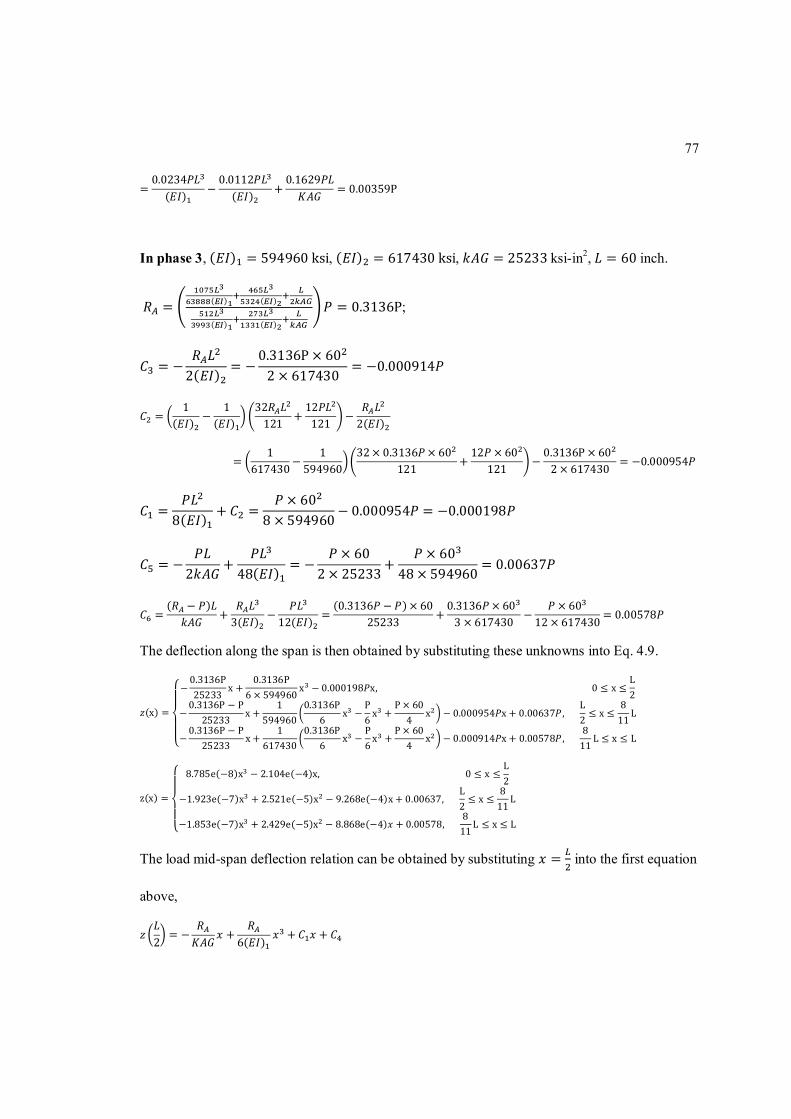
77
=0.0234푃퐿(퐸퐼) −
0.0112푃퐿(퐸퐼) +
0.1629푃퐿퐾퐴퐺 = 0.00359P
In phase 3, (퐸퐼) = 594960ksi, (퐸퐼) = 617430ksi, 푘퐴퐺 = 25233 ksi-in2,퐿 = 60 inch.
푅 = ( ) ( )
( ) ( )
푃 = 0.3136P;
퐶 = −푅 퐿2(퐸퐼)
= −0.3136P × 602 × 617430
= −0.000914푃
퐶 =1
(퐸퐼) −1
(퐸퐼)32푅 퐿121 +
12푃퐿121 −
푅 퐿2(퐸퐼)
=1
617430−1
59496032× 0.3136푃× 60
121 +12푃 × 60
121 −0.3136P × 602 × 617430 = −0.000954푃
퐶 =푃퐿
8(퐸퐼)+ 퐶 =
푃 × 608 × 594960
− 0.000954푃 = −0.000198푃
퐶 = −푃퐿2푘퐴퐺
+푃퐿
48(퐸퐼)= −
푃 × 602 × 25233
+푃 × 60
48 × 594960= 0.00637푃
퐶 =(푅 − 푃)퐿푘퐴퐺 +
푅 퐿3(퐸퐼) −
푃퐿12(퐸퐼) =
(0.3136푃 − 푃)× 6025233 +
0.3136푃× 603 × 617430 −
푃 × 6012 × 617430 = 0.00578푃
The deflection along the span is then obtained by substituting these unknowns into Eq. 4.9.
푧(x) =
⎩⎪⎨
⎪⎧−
0.3136P25233
x +0.3136P
6 × 594960x − 0.000198푃x,0 ≤ x ≤
L2
−0.3136P − P
25233x +
1594960
0.3136P6
x −P6x +
P × 604
x − 0.000954푃x + 0.00637푃,L2≤ x ≤
811
L
−0.3136P − P
25233x +
1617430
0.3136P6
x −P6x +
P × 604
x − 0.000914푃x + 0.00578푃,811
L ≤ x ≤ L
z(x) =
⎩⎪⎨
⎪⎧ 8.785e(−8)x − 2.104e(−4)x,0 ≤ x ≤
L2
−1.923e(−7)x + 2.521e(−5)x − 9.268e(−4)x + 0.00637,L2≤ x ≤
811
L
−1.853e(−7)x + 2.429e(−5)x − 8.868e(−4)푥 + 0.00578,811L ≤ x ≤ L
The load mid-span deflection relation can be obtained by substituting 푥 = into the first equation
above,
푧퐿2
= −푅퐾퐴퐺
푥 +푅
6(퐸퐼)푥 + 퐶 푥 + 퐶

78
= −0.3136푃퐾퐴퐺
퐿2
+0.3136푃P6(퐸퐼)
퐿2
+푃퐿
8(퐸퐼)+
1(퐸퐼)
−1
(퐸퐼)32 × 0.3136푃P퐿
121+12푃퐿121
−0.3136푃퐿2(퐸퐼)
퐿2
=0.022푃퐿(퐸퐼) −
0.0127푃퐿(퐸퐼) +
0.1568푃퐿퐾퐴퐺 = 0.00392P

79
Appendix B
MATLAB Program
%% Empty tube-WSU % modulus of elasticity(ksi): Eht=3880;Ehc=4160; % E for horizontal wall (flange) in tension and compression Evt=3430;Evc=4220; % E for vertical wall (web) in tension and compression % define the area of plate elements(inch): t1=0.2; b1= 6.10; % first horizontal wall element t2=0.2; b2= 5.57; % second horizontal wall element t3=0.2; b3= 3.94; % third horizontal wall element t4=0.2; b4= 3.46; % fourth horizontal wall element t5=0.266; b5= 4.08; % one vertical wall element, has been transfered to element perpendicular to horizontal line % define the distance of each element (center) to the top surface (for pultruded tube): % height between four horizontal elements: 0.906,1.868,0.906. h1=t1/2; h2=0.906+t1+t2/2; h3=1.868+0.906+t1+t2+t3/2;h4=0.906+1.868+0.906+t1+t2+t3+t4/2; syms x A B; %distance to the top % calculate neutral axis position A=(Ehc*t1*b1*h1+Ehc*t2*b2*h2+Eht*t3*b3*h3+Eht*t4*b4*h4+Evc*t5*2*(x-t1)*(x+t1)/2+Evt*t5*2*(b5+t1-x)*((x+t1)/2+b5/2)) B=(Ehc*t1*b1+Ehc*t2*b2+Eht*t3*b3+Eht*t4*b4+Evc*t5*2*(x-t1)+Evt*t5*2*(b5+t1-x)) % NA=A/B solve x*(Ehc*t1*b1+Ehc*t2*b2+Eht*t3*b3+Eht*t4*b4+Evc*t5*2*(x-t1)+Evt*t5*2*(b5+t1-x))=(Ehc*t1*b1*h1+Ehc*t2*b2*h2+Eht*t3*b3*h3+Eht*t4*b4*h4+Evc*t5*2*(x-t1)*(x+t1)/2+Evt*t5*2*(b5+t1-x)*((x+t1)/2+b5/2)) x=1.9183 %% neutral axis position, measured from wider flange side EI1=(Ehc*t1*b1)*(x-h1)^2+(Ehc*t2*b2)*(x-h2)^2+(Eht*t3*b3)*(h3-x)^2+(Eht*t4*b4)*(h4-x)^2 EI2=(Evc*t5*2*(x-t1)*(x-x/2-t1/2)^2+Evc*t5*2/12*(x-0.2)^3)+(Evt*t5*2*(4.48-t4-x)*((4.48-x-t4)/2)^2+Evt*t5*2/12*(4.48-x-t4)^3) EI=EI1+EI2

80
EI=52095 %% Epoxy grouted tube-Wide cell-WSU % modulus of elasticity(ksi): Eht=3880;Ehc=4160; % E for horizontal wall (flange) in tension and compression Evt=3430;Evc=4220; % E for vertical wall (web) in tension and compression Eg=2100; % E for epoxy grout in tension and compression % define the area of plate elements(inch): t1=0.2; b1= 6.10; % first horizontal wall element t2=0.2; b2= 5.57; % second horizontal wall element t3=0.2; b3= 3.94; % third horizontal wall element t4=0.2; b4= 3.46; % fourth horizontal wall element t5=0.266; b5= 4.08; % one vertical wall element, has been transfered to element perpendicular to horizontal line t6=0.152; b6= 35; % narrow side outer wrap element t7=0.152; b7= 38; % wide side outer wrap element t8=0.1615; b8= 4.48; % one vertical outer wrap element, has been transfered to element perpendicular to horizontal line Agw=5.237;NAgw=0.466;Agn=3.026;NAgn=0.4684;Igw=0.358;Ign=0.206; % define the distance of each element (center) to the top surface (for pultruded tube): % height between four horizontal elements: 0.906,1.868,0.906. h1=t1/2; h2=0.906+t1+t2/2; h3=1.868+0.906+t1+t2+t3/2;h4=0.906+1.868+0.906+t1+t2+t3+t4/2; syms x A B; %distance to the top % calculate neutral axis position A=(Ehc*t1*b1*h1+Ehc*t2*b2*h2+Eht*t3*b3*h3+Eht*t4*b4*h4+Evc*t5*2*(x-t1)*(x+t1)/2+Evt*t5*2*(b5+t1-x)*((x+t1)/2+b5/2)+Eg*Agw*(NAgw+t1)) B=(Ehc*t1*b1+Ehc*t2*b2+Eht*t3*b3+Eht*t4*b4+Evc*t5*2*(x-t1)+Evt*t5*2*(b5+t1-x)+Eg*Agw) % NA=A/B solve x*(Ehc*t1*b1+Ehc*t2*b2+Eht*t3*b3+Eht*t4*b4+Evc*t5*2*(x-t1)+Evt*t5*2*(b5+t1-x)+Eg*Agw)=(Ehc*t1*b1*h1+Ehc*t2*b2*h2+Eht*t3*b3*h3+Eht*t4*b4*h4+Evc*t5*2*(x-t1)*(x+t1)/2+Evt*t5*2*(b5+t1-x)*((x+t1)/2+b5/2)+Eg*Agw*(NAgw+t1)) x=1.5462 %% neutral axis position, measured from wider flange side EI1=(Ehc*t1*b1)*(x-h1)^2+(Ehc*t2*b2)*(x-h2)^2+(Eht*t3*b3)*(h3-x)^2+(Eht*t4*b4)*(h4-x)^2 EI2=(Evc*t5*2*(x-t1)*(x-x/2-t1/2)^2+Evc*t5*2/12*(x-0.2)^3)+(Evt*t5*2*(4.48-t4-x)*((4.48-x-t4)/2)^2+Evt*t5*2/12*(4.48-x-t4)^3)

81
EI3=Eg*Agw*(x-NAgw-t1)^2+Eg*Igw EI=EI1+EI2+EI3 EI=64482 %% Epoxy grouted tube-Narrow cell-WSD % modulus of elasticity(ksi): Eht=3880;Ehc=4160; % E for horizontal wall (flange) in tension and compression Evt=3430;Evc=4220; % E for vertical wall (web) in tension and compression Eg=2100; % E for epoxy grout in tension and compression % define the area of plate elements(inch): t1=0.2; b1= 6.10; % first horizontal wall element t2=0.2; b2= 5.57; % second horizontal wall element t3=0.2; b3= 3.94; % third horizontal wall element t4=0.2; b4= 3.46; % fourth horizontal wall element t5=0.266; b5= 4.08; % one vertical wall element, has been transfered to element perpendicular to horizontal line t6=0.152; b6= 35; % narrow side outer wrap element t7=0.152; b7= 38; % wide side outer wrap element t8=0.1615; b8= 4.48; % one vertical outer wrap element, has been transfered to element perpendicular to horizontal line Agw=5.237;NAgw=0.466;Agn=3.026;NAgn=0.4684;Igw=0.358;Ign=0.206; % define the distance of each element (center) to the Bottom surface (for pultruded tube): % height between four horizontal elements: 0.906,1.868,0.906. h1=t1/2; h2=0.906+t1+t2/2; h3=1.868+0.906+t1+t2+t3/2;h4=0.906+1.868+0.906+t1+t2+t3+t4/2; syms x A B; %distance to the top % calculate neutral axis position A=(Eht*t1*b1*h1+Eht*t2*b2*h2+Ehc*t3*b3*h3+Ehc*t4*b4*h4+Evt*t5*2*(x-t1)*(x+t1)/2+Evc*t5*2*(b5+t1-x)*((x+t1)/2+b5/2)+Eg*Agn*(4.48-NAgn-t4)) B=(Eht*t1*b1+Eht*t2*b2+Ehc*t3*b3+Ehc*t4*b4+Evt*t5*2*(x-t1)+Evc*t5*2*(b5+t1-x)+Eg*Agn) % NA=A/B solve x*(Eht*t1*b1+Eht*t2*b2+Ehc*t3*b3+Ehc*t4*b4+Evt*t5*2*(x-t1)+Evc*t5*2*(b5+t1-x)+Eg*Agn)=(Eht*t1*b1*h1+Eht*t2*b2*h2+Ehc*t3*b3*h3+Ehc*t4*b4*h4+Evt*t5*2*(x-t1)*(x+t1)/2+Evc*t5*2*(b5+t1-x)*((x+t1)/2+b5/2)+Eg*Agn*(4.48-NAgn-t4)) x=2.4063 %% neutral axis position, measured from wider flange side EI1=(Eht*t1*b1)*(x-h1)^2+(Eht*t2*b2)*(x-h2)^2+(Ehc*t3*b3)*(h3-x)^2+(Ehc*t4*b4)*(h4-x)^2

82
EI2=(Evt*t5*2*(x-t1)*(x-x/2-t1/2)^2+Evt*t5*2/12*(x-0.2)^3)+(Evc*t5*2*(4.48-t4-x)*((4.48-x-t4)/2)^2+Evc*t5*2/12*(4.48-x-t4)^3) EI3=Eg*Ign+Eg*Agn*(4.48-x-t4-NAgn)^2 EI=EI1+EI2+EI3 EI=68288 %% Cementitious grouted tube-Wide cell-WSU % modulus of elasticity(ksi): Eht=3880;Ehc=4160; % E for horizontal wall (flange) in tension and compression Evt=3430;Evc=4220; % E for vertical wall (web) in tension and compression Eg=950; % E for cementitious grout in tension and compression % define the area of plate elements(inch): t1=0.2; b1= 6.10; % first horizontal wall element t2=0.2; b2= 5.57; % second horizontal wall element t3=0.2; b3= 3.94; % third horizontal wall element t4=0.2; b4= 3.46; % fourth horizontal wall element t5=0.266; b5= 4.08; % one vertical wall element, has been transfered to element perpendicular to horizontal line t6=0.152; b6= 35; % narrow side outer wrap element t7=0.152; b7= 38; % wide side outer wrap element t8=0.1615; b8= 4.48; % one vertical outer wrap element, has been transfered to element perpendicular to horizontal line Agw=5.237;NAgw=0.466;Agn=3.026;NAgn=0.4684;Igw=0.358;Ign=0.206; % define the distance of each element (center) to the top surface (for pultruded tube): % height between four horizontal elements: 0.906,1.868,0.906. h1=t1/2; h2=0.906+t1+t2/2; h3=1.868+0.906+t1+t2+t3/2;h4=0.906+1.868+0.906+t1+t2+t3+t4/2; syms x A B; %distance to the top % calculate neutral axis position A=(Ehc*t1*b1*h1+Ehc*t2*b2*h2+Eht*t3*b3*h3+Eht*t4*b4*h4+Evc*t5*2*(x-t1)*(x+t1)/2+Evt*t5*2*(b5+t1-x)*((x+t1)/2+b5/2)+Eg*Agw*(NAgw+t1)) B=(Ehc*t1*b1+Ehc*t2*b2+Eht*t3*b3+Eht*t4*b4+Evc*t5*2*(x-t1)+Evt*t5*2*(b5+t1-x)+Eg*Agw) % NA=A/B solve x*(Ehc*t1*b1+Ehc*t2*b2+Eht*t3*b3+Eht*t4*b4+Evc*t5*2*(x-t1)+Evt*t5*2*(b5+t1-x)+Eg*Agw)=(Ehc*t1*b1*h1+Ehc*t2*b2*h2+Eht*t3*b3*h3+Eht*t4*b4*h4+Evc*t5*2*(x-t1)*(x+t1)/2+Evt*t5*2*(b5+t1-x)*((x+t1)/2+b5/2)+Eg*Agw*(NAgw+t1)) x=1.7 %% neutral axis position, measured from wider flange side

83
EI1=(Ehc*t1*b1)*(x-h1)^2+(Ehc*t2*b2)*(x-h2)^2+(Eht*t3*b3)*(h3-x)^2+(Eht*t4*b4)*(h4-x)^2 EI2=(Evc*t5*2*(x-t1)*(x-x/2-t1/2)^2+Evc*t5*2/12*(x-0.2)^3)+(Evt*t5*2*(4.48-t4-x)*((4.48-x-t4)/2)^2+Evt*t5*2/12*(4.48-x-t4)^3) EI3=Eg*Agw*(x-NAgw-t1)^2+Eg*Igw EI=EI1+EI2+EI3 EI=59613 %% Cementitious grouted tube-Narrow cell-WSD % modulus of elasticity(ksi): Eht=3880;Ehc=4160; % E for horizontal wall (flange) in tension and compression Evt=3430;Evc=4220; % E for vertical wall (web) in tension and compression Eg=950; % E for cementitious grout in tension and compression % define the area of plate elements(inch): t1=0.2; b1= 6.10; % first horizontal wall element t2=0.2; b2= 5.57; % second horizontal wall element t3=0.2; b3= 3.94; % third horizontal wall element t4=0.2; b4= 3.46; % fourth horizontal wall element t5=0.266; b5= 4.08; % one vertical wall element, has been transfered to element perpendicular to horizontal line t6=0.152; b6= 35; % narrow side outer wrap element t7=0.152; b7= 38; % wide side outer wrap element t8=0.1615; b8= 4.48; % one vertical outer wrap element, has been transfered to element perpendicular to horizontal line Agw=5.237;NAgw=0.466;Agn=3.026;NAgn=0.4684;Igw=0.358;Ign=0.206; % define the distance of each element (center) to the Bottom surface (for pultruded tube): % height between four horizontal elements: 0.906,1.868,0.906. h1=t1/2; h2=0.906+t1+t2/2; h3=1.868+0.906+t1+t2+t3/2;h4=0.906+1.868+0.906+t1+t2+t3+t4/2; syms x A B; %distance to the top % calculate neutral axis position A=(Eht*t1*b1*h1+Eht*t2*b2*h2+Ehc*t3*b3*h3+Ehc*t4*b4*h4+Evt*t5*2*(x-t1)*(x+t1)/2+Evc*t5*2*(b5+t1-x)*((x+t1)/2+b5/2)+Eg*Agn*(4.48-NAgn-t4)) B=(Eht*t1*b1+Eht*t2*b2+Ehc*t3*b3+Ehc*t4*b4+Evt*t5*2*(x-t1)+Evc*t5*2*(b5+t1-x)+Eg*Agn) % NA=A/B solve x*(Eht*t1*b1+Eht*t2*b2+Ehc*t3*b3+Ehc*t4*b4+Evt*t5*2*(x-t1)+Evc*t5*2*(b5+t1-x)+Eg*Agn)=(Eht*t1*b1*h1+Eht*t2*b2*h2+Ehc*t3*b3*h3+Ehc*t4*b4*h4+Evt*t5*2*(x-t1)*(x+t1)/2+Evc*t5*2*(b5+t1-x)*((x+t1)/2+b5/2)+Eg*Agn*(4.48-NAgn-t4))

84
x=2.253 %% neutral axis position, measured from wider flange side EI1=(Eht*t1*b1)*(x-h1)^2+(Eht*t2*b2)*(x-h2)^2+(Ehc*t3*b3)*(h3-x)^2+(Ehc*t4*b4)*(h4-x)^2 EI2=(Evt*t5*2*(x-t1)*(x-x/2-t1/2)^2+Evt*t5*2/12*(x-0.2)^3)+(Evc*t5*2*(4.48-t4-x)*((4.48-x-t4)/2)^2+Evc*t5*2/12*(4.48-x-t4)^3) EI3=Eg*Ign+Eg*Agn*(4.48-x-t4-NAgn)^2 EI=EI1+EI2+EI3 EI=61796 %% Empty Panel-WSD % modulus of elasticity(ksi): Eht=3880;Ehc=4160; % E for horizontal wall (flange) in tension and compression Evt=3430;Evc=4220; % E for vertical wall (web) in tension and compression Ew=2340; % E for outer wrap in tension and compression % define the area of plate elements(inch): t1=0.2; b1= 6.10; % first horizontal wall element t2=0.2; b2= 5.57; % second horizontal wall element t3=0.2; b3= 3.94; % third horizontal wall element t4=0.2; b4= 3.46; % fourth horizontal wall element t5=0.266; b5= 4.08; % one vertical wall element, has been transfered to element perpendicular to horizontal line t6=0.152; b6= 35; % narrow side outer wrap element t7=0.152; b7= 38; % wide side outer wrap element t8=0.1615; b8= 4.48; % one vertical outer wrap element, has been transfered to element perpendicular to horizontal line Agw=5.237;NAgw=0.466;Agn=3.026;NAgn=0.4684;Igw=0.358;Ign=0.206; % define the distance of each element (center) to the top surface (for pultruded tube): % height between four horizontal elements: 0.906,1.868,0.906. h1=t1/2+t6; h2=0.906+t1+t2/2+t6; h3=1.868+0.906+t1+t2+t3/2+t6;h4=0.906+1.868+0.906+t1+t2+t3+t4/2+t6;h6=t6/2;h7=4.784-t7/2;h8=4.784/2; syms x A B; %distance to the top h51=(x+0.152+0.2)/2;b51=x-0.152-0.2;h52=h51+4.08/2;b52=4.08-b51; % calculate neutral axis position A=((Ehc*t1*b1*h1*3+Ehc*t4*b4*h1*4)+(Ehc*t2*b2*h2*3+Ehc*t3*b3*h2*4)+(Eht*t3*b3*h3*3+Eht*t2*b2*h3*4)+(Eht*t4*b4*h4*3+Eht*t1*b1*h4*4)+(Evc*t5*2*(x-0.152-0.2)*((x+0.152+0.2)/2)*7)+(Evt*t5*2*(4.08-(x-0.152-0.2))*((x+0.152+0.2)/2+4.08/2)*7)+(Ew*t6*b6*h6)+(Ew*t7*b7*h7)+(Ew*t8*b8*h8)) B=((Ehc*t1*b1*3+Ehc*t4*b4*4)+(Ehc*t2*b2*3+Ehc*t3*b3*4)+(Eht*t3*b3*3+Eht*t2*b2*4)+(Eht*t4*b4*3+Eht*t1*b1*4)+(Evc*t5*2*(x-0.152-

85
0.2)*7)+(Evt*t5*2*(4.08-(x-0.152-0.2))*7)+(Ew*t6*b6)+(Ew*t7*b7)+(Ew*t8*2*b8)) % NA=A/B solve x*((Ehc*t1*b1*3+Ehc*t4*b4*4)+(Ehc*t2*b2*3+Ehc*t3*b3*4)+(Eht*t3*b3*3+Eht*t2*b2*4)+(Eht*t4*b4*3+Eht*t1*b1*4)+(Evc*t5*2*(x-0.152-0.2)*7)+(Evt*t5*2*(4.08-(x-0.152-0.2))*7)+(Ew*t6*b6)+(Ew*t7*b7)+(Ew*t8*2*b8))=((Ehc*t1*b1*h1*3+Ehc*t4*b4*h1*4)+(Ehc*t2*b2*h2*3+Ehc*t3*b3*h2*4)+(Eht*t3*b3*h3*3+Eht*t2*b2*h3*4)+(Eht*t4*b4*h4*3+Eht*t1*b1*h4*4)+(Evc*t5*2*(x-0.152-0.2)*((x+0.152+0.2)/2)*7)+(Evt*t5*2*(4.08-(x-0.152-0.2))*((x+0.152+0.2)/2+4.08/2)*7)+(Ew*t6*b6*h6)+(Ew*t7*b7*h7)+(Ew*t8*b8*h8)) x=2.3522 %% neutral axis position, measured from wider flange side EI1=(Ehc*t1*b1*3+Ehc*t4*b4*4)*(x-h1)^2+(Ehc*t2*b2*3+Ehc*t3*b3*4)*(x-h2)^2+(Eht*t3*b3*3+Eht*t2*b2*4)*(h3-x)^2+(Eht*t4*b4*3+Eht*t1*b1*4)*(h4-x)^2 EI2=(Evc*t5*2*(x-0.152-0.2)*7*(x-h51)^2+Evc*t5*2/12*b51^3*7)+(Evt*t5*2*(4.08-(x-0.152-0.2))*7*(x-h52)^2+Evt*t5*2/12*b52^3*7) EI3=(Ew*t6*b6)*(x-h6)^2+(Ew*t7*b7)*(x-h7)^2+(Ew*t8*2*b8)*(x-h8)^2+Ew*t8*2/12*4.48^3 EI=EI1+EI2+EI3 EI=528600 %% Epoxy grouted panel(Alternate cell filled-WSD) % modulus of elasticity(ksi): Eht=3880;Ehc=4160; % E for horizontal wall (flange) in tension and compression Evt=3430;Evc=4220; % E for vertical wall (web) in tension and compression Ew=2340; % E for outer wrap in tension and compression Eg=2100; % E for epoxy grout in tension and compression % define the area of plate elements(inch): t1=0.2; b1= 6.10; % first horizontal wall element t2=0.2; b2= 5.57; % second horizontal wall element t3=0.2; b3= 3.94; % third horizontal wall element t4=0.2; b4= 3.46; % fourth horizontal wall element t5=0.266; b5= 4.08; % one vertical wall element, has been transfered to element perpendicular to horizontal line t6=0.152; b6= 35; % narrow side outer wrap element t7=0.152; b7= 38; % wide side outer wrap element t8=0.1615; b8= 4.48; % one vertical outer wrap element, has been transfered to element perpendicular to horizontal line Agw=5.237;NAgw=0.466;Agn=3.026;NAgn=0.4684;Igw=0.358;Ign=0.206;

86
% define the distance of each element (center) to the top surface (for pultruded tube): % height between four horizontal elements: 0.906,1.868,0.906. h1=t1/2+t6; h2=0.906+t1+t2/2+t6; h3=1.868+0.906+t1+t2+t3/2+t6;h4=0.906+1.868+0.906+t1+t2+t3+t4/2+t6;h5=4.784/2-4.075/4;h6=t6/2;h7=4.784-t7/2;h8=4.784/2;h9=0.446+0.2+0.152;h10=4.784-0.2-0.152-0.446; syms x A B; %distance to the top h51=(x+0.152+0.2)/2;b51=x-0.152-0.2;h52=h51+4.08/2;b52=4.08-b51; % calculate neutral axis position A=((Ehc*t1*b1*h1*3+Ehc*t4*b4*h1*4)+(Ehc*t2*b2*h2*3+Ehc*t3*b3*h2*4)+(Eht*t3*b3*h3*3+Eht*t2*b2*h3*4)+(Eht*t4*b4*h4*3+Eht*t1*b1*h4*4)+(Evc*t5*2*(x-0.152-0.2)*((x+0.152+0.2)/2)*7)+(Evt*t5*2*(4.075-(x-0.152-0.2))*((x+0.152+0.2)/2+4.075/2)*7)+(Ew*t6*b6*h6)+(Ew*t7*b7*h7)+(Ew*t8*2*b8*h8)+Eg*(5.237*3*(0.446+0.2+0.152)+5.237*4*(4.784-0.2-0.152-0.446))) B=((Ehc*t1*b1*3+Ehc*t4*b4*4)+(Ehc*t2*b2*3+Ehc*t3*b3*4)+(Eht*t3*b3*3+Eht*t2*b2*4)+(Eht*t4*b4*3+Eht*t1*b1*4)+(Evc*t5*2*(x-0.152-0.2)*7)+(Evt*t5*2*(4.08-(x-0.152-0.2))*7)+(Ew*t6*b6)+(Ew*t7*b7)+(Ew*t8*2*b8)+Eg*(5.237*3+5.237*4)) % NA=A/B solve x*((Ehc*t1*b1*3+Ehc*t4*b4*4)+(Ehc*t2*b2*3+Ehc*t3*b3*4)+(Eht*t3*b3*3+Eht*t2*b2*4)+(Eht*t4*b4*3+Eht*t1*b1*4)+(Evc*t5*2*(x-0.152-0.2)*7)+(Evt*t5*2*(4.08-(x-0.152-0.2))*7)+(Ew*t6*b6)+(Ew*t7*b7)+(Ew*t8*2*b8)+Eg*(5.237*3+5.237*4))=((Ehc*t1*b1*h1*3+Ehc*t4*b4*h1*4)+(Ehc*t2*b2*h2*3+Ehc*t3*b3*h2*4)+(Eht*t3*b3*h3*3+Eht*t2*b2*h3*4)+(Eht*t4*b4*h4*3+Eht*t1*b1*h4*4)+(Evc*t5*2*(x-0.152-0.2)*((x+0.152+0.2)/2)*7)+(Evt*t5*2*(4.075-(x-0.152-0.2))*((x+0.152+0.2)/2+4.075/2)*7)+(Ew*t6*b6*h6)+(Ew*t7*b7*h7)+(Ew*t8*2*b8*h8)+Eg*(5.237*3*(0.446+0.2+0.152)+5.237*4*(4.784-0.2-0.152-0.446))) x=2.4370 %% neutral axis position, measured from narrow flange side EI1=(Ehc*t1*b1*3+Ehc*t4*b4*4)*(x-h1)^2+(Ehc*t2*b2*3+Ehc*t3*b3*4)*(x-h2)^2+(Eht*t3*b3*3+Eht*t2*b2*4)*(h3-x)^2+(Eht*t4*b4*3+Eht*t1*b1*4)*(h4-x)^2 EI2=(Evc*t5*2*(x-0.152-0.2)*7*(x-h51)^2+Evc*t5*2/12*b51^3*7)+(Evt*t5*2*(4.08-(x-0.152-0.2))*7*(x-h52)^2+Evt*t5*2/12*b52^3*7) EI3=(Ew*t6*b6)*(x-h6)^2+(Ew*t7*b7)*(x-h7)^2+(Ew*t8*2*b8)*(x-h8)^2+Ew*t8*2/12*4.48^3 EI4=Eg*(Agw*3*(x-h9)^2+Agw*4*(x-h10)^2)+Eg*7*Igw EI=EI1+EI2+EI3+EI4 EI=709970 %% Epoxy grouted panel(Alternate cell filled-WSD)-cracked (4 cells) % modulus of elasticity(ksi): Eht=3880;Ehc=4160; % E for horizontal wall (flange) in tension and compression

87
Evt=3430;Evc=4220; % E for vertical wall (web) in tension and compression Ew=2340; % E for outer wrap in tension and compression Eg=2100; % E for epoxy grout in tension and compression % define the area of plate elements(inch): t1=0.2; b1= 6.10; % first horizontal wall element t2=0.2; b2= 5.57; % second horizontal wall element t3=0.2; b3= 3.94; % third horizontal wall element t4=0.2; b4= 3.46; % fourth horizontal wall element t5=0.266; b5= 4.08; % one vertical wall element, has been transfered to element perpendicular to horizontal line t6=0.152; b6= 35; % narrow side outer wrap element t7=0.152; b7= 38; % wide side outer wrap element t8=0.1615; b8= 4.48; % one vertical outer wrap element, has been transfered to element perpendicular to horizontal line Agw=5.237;NAgw=0.466;Agn=3.026;NAgn=0.4684;Igw=0.358;Ign=0.206; % define the distance of each element (center) to the top surface (for pultruded tube): % height between four horizontal elements: 0.906,1.868,0.906. h1=t1/2+t6; h2=0.906+t1+t2/2+t6; h3=1.868+0.906+t1+t2+t3/2+t6;h4=0.906+1.868+0.906+t1+t2+t3+t4/2+t6;h5=4.784/2-4.075/4;h6=t6/2;h7=4.784-t7/2;h8=4.784/2;h9=0.446+0.2+0.152;h10=4.784-0.2-0.152-0.446; syms x A B; %distance to the top h51=(x+0.152+0.2)/2;b51=x-0.152-0.2;h52=h51+4.08/2;b52=4.08-b51; % calculate neutral axis position A=((Ehc*t1*b1*h1*3+Ehc*t4*b4*h1*4)+(Ehc*t2*b2*h2*3+Ehc*t3*b3*h2*4)+(Eht*t3*b3*h3*3+Eht*t2*b2*h3*4)+(Eht*t4*b4*h4*3+Eht*t1*b1*h4*4)+(Evc*t5*2*(x-0.152-0.2)*((x+0.152+0.2)/2)*7)+(Evt*t5*2*(4.075-(x-0.152-0.2))*((x+0.152+0.2)/2+4.075/2)*7)+(Ew*t6*b6*h6)+(Ew*t7*b7*h7)+(Ew*t8*2*b8*h8)+Eg*(5.237*3*(0.446+0.2+0.152))) B=((Ehc*t1*b1*3+Ehc*t4*b4*4)+(Ehc*t2*b2*3+Ehc*t3*b3*4)+(Eht*t3*b3*3+Eht*t2*b2*4)+(Eht*t4*b4*3+Eht*t1*b1*4)+(Evc*t5*2*(x-0.152-0.2)*7)+(Evt*t5*2*(4.08-(x-0.152-0.2))*7)+(Ew*t6*b6)+(Ew*t7*b7)+(Ew*t8*2*b8)+Eg*(5.237*3)) % NA=A/B solve x*((Ehc*t1*b1*3+Ehc*t4*b4*4)+(Ehc*t2*b2*3+Ehc*t3*b3*4)+(Eht*t3*b3*3+Eht*t2*b2*4)+(Eht*t4*b4*3+Eht*t1*b1*4)+(Evc*t5*2*(x-0.152-0.2)*7)+(Evt*t5*2*(4.08-(x-0.152-0.2))*7)+(Ew*t6*b6)+(Ew*t7*b7)+(Ew*t8*2*b8)+Eg*(5.237*3))=((Ehc*t1*b1*h1*3+Ehc*t4*b4*h1*4)+(Ehc*t2*b2*h2*3+Ehc*t3*b3*h2*4)+(Eht*t3*b3*h3*3+Eht*t2*b2*h3*4)+(Eht*t4*b4*h4*3+Eht*t1*b1*h4*4)+(Evc*t5*2*(x-0.152-0.2)*((x+0.152+0.2)/2)*7)+(Evt*t5*2*(4.075-(x-0.152-0.2))*((x+0.152+0.2)/2+4.075/2)*7)+(Ew*t6*b6*h6)+(Ew*t7*b7*h7)+(Ew*t8*2*b8*h8)+Eg*(5.237*3*(0.446+0.2+0.152))) x=2.1620 %% neutral axis position, measured from narrow flange side

88
EI1=(Ehc*t1*b1*3+Ehc*t4*b4*4)*(x-h1)^2+(Ehc*t2*b2*3+Ehc*t3*b3*4)*(x-h2)^2+(Eht*t3*b3*3+Eht*t2*b2*4)*(h3-x)^2+(Eht*t4*b4*3+Eht*t1*b1*4)*(h4-x)^2 EI2=(Evc*t5*2*(x-0.152-0.2)*7*(x-h51)^2+Evc*t5*2/12*b51^3*7)+(Evt*t5*2*(4.08-(x-0.152-0.2))*7*(x-h52)^2+Evt*t5*2/12*b52^3*7) EI3=(Ew*t6*b6)*(x-h6)^2+(Ew*t7*b7)*(x-h7)^2+(Ew*t8*2*b8)*(x-h8)^2+Ew*t8*2/12*4.48^3 EI4=Eg*(Agw*3*(x-h9)^2)+Eg*3*Igw EI=EI1+EI2+EI3+EI4 EI=594960 %% Epoxy grouted panel(Alternate cell filled-WSU)-cracked (3 cells) % modulus of elasticity(ksi): Eht=3880;Ehc=4160; % E for horizontal wall (flange) in tension and compression Evt=3430;Evc=4220; % E for vertical wall (web) in tension and compression Ew=2340; % E for outer wrap in tension and compression Eg=2100; % E for epoxy grout in tension and compression % define the area of plate elements(inch): t1=0.2; b1= 6.10; % first horizontal wall element t2=0.2; b2= 5.57; % second horizontal wall element t3=0.2; b3= 3.94; % third horizontal wall element t4=0.2; b4= 3.46; % fourth horizontal wall element t5=0.266; b5= 4.08; % one vertical wall element, has been transfered to element perpendicular to horizontal line t6=0.152; b6= 35; % narrow side outer wrap element t7=0.152; b7= 38; % wide side outer wrap element t8=0.1615; b8= 4.48; % one vertical outer wrap element, has been transfered to element perpendicular to horizontal line Agw=5.237;NAgw=0.466;Agn=3.026;NAgn=0.4684;Igw=0.358;Ign=0.206; % define the distance of each element (center) to the top surface (for pultruded tube): % height between four horizontal elements: 0.906,1.868,0.906. h1=t1/2+t6; h2=0.906+t1+t2/2+t6; h3=1.868+0.906+t1+t2+t3/2+t6;h4=0.906+1.868+0.906+t1+t2+t3+t4/2+t6;h5=4.784/2-4.075/4;h6=t6/2;h7=4.784-t7/2;h8=4.784/2;h9=0.446+0.2+0.152;h10=4.784-0.2-0.152-0.446; syms x A B; %distance to the top h51=(x+0.152+0.2)/2;b51=x-0.152-0.2;h52=h51+4.08/2;b52=4.08-b51; % h5=(NA+t1)/2 & h5=((NA+t1)/2+b5/2); % calculate neutral axis position A=((Ehc*t1*b1*h1*3+Ehc*t4*b4*h1*4)+(Ehc*t2*b2*h2*3+Ehc*t3*b3*h2*4)+(Eht*t3*b3*h3*3+Eht*t2*b2*h3*4)+(Eht*t4*b4*h4*3+Eht*t1*b1*h4*4)+(Evc*t5*2*(x-0.152-0.2)*((x+0.152+0.2)/2)*7)+(Evt*t5*2*(4.075-(x-0.152-0.2))*((x+0.152+0.2)/2+4.075/2)*7)+(Ew*t6*b6*h6)+(Ew*t7*b7*h7)+(Ew*t8*2*b8*h8)+Eg*(5.237*4*(4.784-0.2-0.152-0.446)))

89
B=((Ehc*t1*b1*3+Ehc*t4*b4*4)+(Ehc*t2*b2*3+Ehc*t3*b3*4)+(Eht*t3*b3*3+Eht*t2*b2*4)+(Eht*t4*b4*3+Eht*t1*b1*4)+(Evc*t5*2*(x-0.152-0.2)*7)+(Evt*t5*2*(4.08-(x-0.152-0.2))*7)+(Ew*t6*b6)+(Ew*t7*b7)+(Ew*t8*2*b8)+Eg*(5.237*4)) % NA=A/B solve x*((Ehc*t1*b1*3+Ehc*t4*b4*4)+(Ehc*t2*b2*3+Ehc*t3*b3*4)+(Eht*t3*b3*3+Eht*t2*b2*4)+(Eht*t4*b4*3+Eht*t1*b1*4)+(Evc*t5*2*(x-0.152-0.2)*7)+(Evt*t5*2*(4.08-(x-0.152-0.2))*7)+(Ew*t6*b6)+(Ew*t7*b7)+(Ew*t8*2*b8)+Eg*(5.237*4))=((Ehc*t1*b1*h1*3+Ehc*t4*b4*h1*4)+(Ehc*t2*b2*h2*3+Ehc*t3*b3*h2*4)+(Eht*t3*b3*h3*3+Eht*t2*b2*h3*4)+(Eht*t4*b4*h4*3+Eht*t1*b1*h4*4)+(Evc*t5*2*(x-0.152-0.2)*((x+0.152+0.2)/2)*7)+(Evt*t5*2*(4.075-(x-0.152-0.2))*((x+0.152+0.2)/2+4.075/2)*7)+(Ew*t6*b6*h6)+(Ew*t7*b7*h7)+(Ew*t8*2*b8*h8)+Eg*(5.237*4*(4.784-0.2-0.152-0.446))) x=2.6452 %% neutral axis position, measured from narrow flange side EI1=(Ehc*t1*b1*3+Ehc*t4*b4*4)*(x-h1)^2+(Ehc*t2*b2*3+Ehc*t3*b3*4)*(x-h2)^2+(Eht*t3*b3*3+Eht*t2*b2*4)*(h3-x)^2+(Eht*t4*b4*3+Eht*t1*b1*4)*(h4-x)^2 EI2=(Evc*t5*2*(x-0.152-0.2)*7*(x-h51)^2+Evc*t5*2/12*b51^3*7)+(Evt*t5*2*(4.08-(x-0.152-0.2))*7*(x-h52)^2+Evt*t5*2/12*b52^3*7) EI3=(Ew*t6*b6)*(x-h6)^2+(Ew*t7*b7)*(x-h7)^2+(Ew*t8*2*b8)*(x-h8)^2+Ew*t8*2/12*4.48^3 EI4=Eg*(Agw*4*(x-h10)^2)+Eg*4*Igw EI=EI1+EI2+EI3+EI4 EI=61743

90
Appendix C
Material Information
This appendix contains ply details of flanges and webs of pultruded tubes. A copy of the
Ipanol E-grout data sheets for epoxy grout and a copy of the Target 1118 Cable Duct Grout for
cementitious grout used in this study are also included.

91
Table C.1. Ply details for flanges of the pultruded tube
Material Angle (O)
Areal Weight (oz/yd2)
Thickness (in)
1 1/2 oz CSM n/a 1.5 0.016 E-TTXM 2308 45 6.27 0.032
90 11.52 -45 6.27 CSM 8.1
Roving - 3.7 ends/in 0 38.3 0.038 E-TTXM 2308 45 6.27 0.032
90 11.52 -45 6.27 CSM 8.1
Roving - 3.7 ends/in 0 38.3 0.038 E-TTXM 2308 45 6.27 0.032
90 11.52 -45 6.27 CSM 8.1
1 1/2 oz CSM n/a 1.5 0.016 Totals 0 76.6 0.204
90 34.6 45/-45 37.6 CSM 27.3
Table C.2. Ply details for webs of the pultruded tube
Material Angle (O)
Areal Weight (oz/yd2)
Thickness (in)
1 1/2 oz CSM n/a 1.5 0.017 E-TTXM 2308 45 6.27 0.032
90 11.52 -45 6.27 CSM 8.1
E-TTXM 2308 45 6.27 0.032 90 11.52 -45 6.27 CSM 8.1
Roving - 7.6 ends/in 0 78.6 0.078 E-TTXM 2308 45 6.27 0.032
90 11.52 -45 6.27 CSM 8.1
E-TTXM 2308 45 6.27 0.032 90 11.52 -45 6.27 CSM 8.1
1 1/2 oz CSM n/a 1.5 0.017 Totals 0 78.6 0.24
90 46.1 45/-45 50.2 CSM 27.3

IPA SYSTEMS, INC
P.O. Box 26869- 2745 North Amber Street, Philadelphia, PA 19134
Tel: 800-523-3834, Fax: 215-425-6234, E-mail: [email protected], Web Site: www.ipasystems.com
IPANOL E-GROUT
High Performance Epoxy Grout IPA SYSTEMS
QUALITY PRODUCTS FOR THE CONCRETE /MASONRY REPAIR INDUSTRY
IPA SYSTEMS
Made in America Oil and chemical resistance
High Strength, with high impact resistance Excellent flowability
High effective bearing area Pre-measured units
Low exotherm cure for deep pour capability
Description
Where to Use
Advantages
Packaging
Ipanol E-Grout is a 3 component, 100% solids, high performance, high quality, engineered Precision epoxy
grout. Available in standard set and extended depth set.
Ipanol E-Grout can be utilized for precision seating of baseplates, grouting under equipment that requires a
high strength grout to withstand heavy impact or vibratory loads. Grouting in anchors and under crane rails.
Use in place of cementitious grouts where chemical resistance is needed.
0.5 cu. ft. (.014cu.m.)kit: 70lb/31.7kg :
Component A: 1 gal./3.8L can Component B: 1 gal./3.8L can
Component C: (1) 60 ib./ 27 kg. bag ( Engineered aggregate)
2. cu. ft. (.056 cu. m.) kit: 280lb./127kg:
Component A: 5 gal./18.9L can Component B: 1 gal./3.8L can
Component C: (4) 60 ib./ 27 kg. bag ( Engineered aggregate)
Technical Data E-Grout Standard E-Grout Extended Depth
ASTM C-579 Compresive Stregth @ 75°F 8-hr 3,200 psi 1,200 psi
16-hr 6,500 psi 3,300 psi
1-day 11,000 psi 6,400 psi
2-day 13,000 psi 9,300 psi
3-day 15,000 psi 10,500 psi
4-day 15,000 psi 11,800 psi
5-day 15,000 psi 12,500 psi
6-day 15,000 psi 12,500 psi
7-day 15,000 psi 12,500 psi
Five Bag Mix 7-day 16,000 psi 14,500 psi
ASTM C-579 Compressive Modulus of Elasticity 2,200,00 psi 2,100,000 psi
ASTM C-1181 Compressive Creep (400 psi, 140°F) <0.005 in/in <0.005 in/in
ASTM C-307 Tensile Strength 2,500 psi 2,200 psi
ASTM C-307 Tensile Modulus of Elasticity 2,100,000 psi 2,000,000 psi
ASTM C-580 Flexural Strength 4,500 psi 4,100 psi
ASTM C-580 Modulus of Elasticity 2,200,000 psi 2,100,000 psi
ASTM C-882 Bond Strength 3,500 psi 3,300 psi
ASTM C-884 Thermal Compatibility pass pass
ASTM D-2471 Gel Time 180 minutes 300 minutes
ASTM D-2471 Peak Exothermic 110°F 90°F
ASTM C-531 Linear Shrinkage on cure 0.005% 0.005%
ASTM C-531 Coefficient of Thermal Expansion:
Standard 16 x 10-6 in/in; °F 18 x 10-6 in/in; °F
>Five-bag max 14 x 10-6 in/in; °F 15 x 10-6 in/in; °F
Pour Depth at 75°F Up to 12 inches Up to 24 inches

IPA SYSTEMS, INC
P.O. Box 26869- 2745 North Amber Street, Philadelphia, PA 19134
Tel: 800-523-3834, Fax: 215-425-6234, E-mail: [email protected], Web Site: www.ipasystems.com
IPA SYSTEMS
QUALITY PRODUCTS FOR THE CONCRETE /MASONRY REPAIR INDUSTRY
IPA SYSTEMS
Surface Prep Fresh concrete: must be allowed to cure for a minimum of 28 days to allow for hydration and shrinkage prior to
placement of Ipanol E-Grout. Please contact IPA’s Technical Service before attempting to place this product on
'green' concrete. All surface contamination must be removed by mechanical means, creating a surface profile of
expose sound aggregate that will provide a strong bond surface for the Ipanol E-Grout.
Old Concrete: Existing foundations should be checked for cracks and repaired. Contact IPA Systems Technical
Service for a complete selection of injection resins and concrete repair materials for a single source repair.
Metal surfaces: All metal surfaces to come in contact with grout should be sandblasted to white metal finish and
wiped clean with solvent. Items not intended to bond to grout, such as leveling screws, wedges, and bolts must be
protected with wax, caulk, duct tape or similar.
Form preparation: Epoxy grouts require heavy duty forms. A sheet of 3/4" plywood and proper bracing should
be used to hold the force of the weight of the grout (140 lbs/64kg per cu ft). Forms should be coated with a
minimum of two coats of an industrial grade paste wax to facilitate removal of forms after cure. Forms should
have 45° angle chamfer strips at all vertical corners and horizontal grout grade elevation in order to eliminate
sharp corners. Caulk, putty, or similar sealant should be used to render the forms "watertight". Forms should be
designed to allow for a hydraulic head to facilitate the placement of Ipanol E-Grout.
Mixing Ipanol E-Grout are shipped in pre-measured .5cu ft / .014m3 unit or a 2 cu ft /.056m3 unit. mix these products
ONLY in complete units . DO NOT THIN or add any solvents prior to mixing.
.5cu ft /.014m3 kit: Pour both liquid components into pail and mix thoroughly for 3 minutes with a Jiffy mixer
on low-speed (300 rpm) until material is a uniform consistency. NOTE: Keep mixer at bottom of pail to avoid
introducing air. After liquid components are mixed, slowly add component C–Aggregate. mix only until all
aggregate is wetted out. Pour mixed grout into forms.
2 cu ft /.056 m3 kit: Component A-Resin is packaged in a 5gal / 18.8L pail, component B-Hardener is
packaged in a 1gal /3.8 L pail, component C-Aggregate is packaged in (4) 60 lb poly-lined bags. Pour
component B-Hardener into 5 gal / 18.8L, pail containing component A-Resin. Mix material thoroughly for 3
minutes with a Jiffy mixer on a low-speed (300 rpm) drill motor until a uniform consistency is achieved.
NOTE: Keep mixer at bottom of pail to avoid introducing air. Pour liquids into mortar mixer, making sure to
remove all resins from sides and bottom of pail with spatula or similar tool. Introduce first bag of component
C-aggregate prior to starting mixer. Start mixer and slowly add the remaining three bags of aggregate. Mix only
until all aggregate is wetted out! DO NOT OVER mix.
Curing temperatures Working Time Initial Cure Time Working Time Initial Cure Time
50°F /16°C 4 hours 42 hours 8 hours 84 hours
55°F /18°C 3 hours 36 hours 7 hours 72 hours
65°F /21°C 2 hours 30 hours 5 hours 60 hours
75°F /24°C 1.5 hours 24 hours 3.5 hours 48 hours
85°F /29°C 45 min 18 hours 2.5 hours 36 hours
95°F /35°C 30 min 12 hours 1.5 hours 24 hours
100°F /38°C 20 min 6 hours 1 hour4 12 hours

IPA SYSTEMS
QUALITY PRODUCTS FOR THE CONCRETE /MASONRY REPAIR INDUSTRY
IPA SYSTEMS
IPA SYSTEMS, INC
P.O. Box 26869- 2745 North Amber Street, Philadelphia, PA 19134
Tel: 800-523-3834, Fax: 215-425-6234, E-mail: [email protected], Web Site: www.ipasystems.com
Clean-up Ipanol E-Grout is are low exotherm grout. The extended working time allows for easy soap & water clean up of
tools mixers and work area while Ipanol E-Grout is in the plastic stage. For materials that have started to set,
Xylol, or other approved solvent may be used.
Application Ipanol E-Grout should be poured into forms at one location in order to allow a uni-directional flow. Use of a
header box will ease the placement of the finished product. Strict adherence to temperature considerations
will assist the placement properties. Check forms frequently for leaks. Plug leaks with a hydraulic cement or
putty. Ipanol E-Grout will not self-seal.
Finishing: When forms are filled to desired elevation, exposed horizontal surfaces of Ipanol E-Grout may be
finished with a surfactant such as Xylol or toluene and a paintbrush or small hand trowel. Surfactant should be
lightly sprayed or misted on surface, DO NOT PUDDLE on surface. This process can be repeated every 30
minutes until surfaces are firm.
Temperature Considerations: Important... Epoxy resins are temperature sensitive and care should be taken
to condition all components (including component “C” aggregate) to between 75°F – 90°F (24°C – 32°C) for a
minimum of 24 hrs. prior to mixing and placement. Temperatures colder than stated range increase viscosity of
resins and inhibit mixing and flow of grouting materials. Temperatures warmer than stated range decrease
viscosity of resins, hasten the cure, and reduce the working time of the grout.
Caution
Clean-up Ipanol E-Grout is are low exotherm grout. The extended working time allows for easy soap & water clean up of
tools mixers and work area while Ipanol E-Grout is in the plastic stage. For materials that have started to set,
Xylol, or other approved solvent may be used.
Safety Considerations:
• Component A – Irritant
• Component B – Corrosive
• Product is a strong sensitizer. Use of safety goggles and chemical resistant gloves are recommended.
• Use of a NIOSH/mSHA organic vapor respirator is recommended if ventilation is inadequate.
• Avoid breathing vapors.
• Avoid skin contact.
First Aid:
EYE CONTACT: Flush immediately with water for at least 15 minutes. Contact physician immediately.
RESPIRATORY CONTACT: Remove person to fresh air.
SKIN CONTACT: Remove any contaminated clothing.
Remove epoxy immediately with a dry cloth or paper towel. Solvents should not be used as they carry the irritant
into the skin. Wash skin thoroughly with soap and water. CURED EPOXY RESINS ARE INNOCUOUS.
FOR INDUSTRIAL USE ONLY: See MSDS for additional precautionary information and health hazard data

This product is warranted and guaranteed to be of good quality. Manufacturer, as its sole and exclusive liability
hereunder, will replace material if proved defective. This warranty and guarantee are expressly in lieu of all
others, express or implied, including any implied warranty of merchantability or fitness for a particular purpose
and may not be extended by representatives or any persons, written sales information, or drawing in any manner
whatsoever. While the manufacturer recommends uses for the product based on tests believed reliable, no
warranties, express or implied, or guarantee can be given as to particular methods of use or application, nor can
performance be warranted, expressly or impliedly, or guaranteed under special conditions. Distributors,
salesperson or company representatives are not authorized to extend or vary any warranties or guarantees beyond
those outlined herein nor may the manufacturer’s or seller’s limitation of liability be waived or altered in any
manner whatsoever.
Warranty
IPA SYSTEMS
QUALITY PRODUCTS FOR THE CONCRETE /MASONRY REPAIR INDUSTRY
IPA SYSTEMS
IPA SYSTEMS, INC
P.O. Box 26869- 2745 North Amber Street, Philadelphia, PA 19134
Tel: 800-523-3834, Fax: 215-425-6234, E-mail: [email protected], Web Site: www.ipasystems.com
Limitations Minimum material, surface and ambient temperature must be 50°F and rising
Temperature will effect flow rate
Do not thin with solvents
Minimum age of concrete should be 28 days
Material needs to be preconditioned to 75°F before application.

1118 GROUT (UNSANDED SILICA FUME GROUT)
Product performance is affected by many factors, including storage, method and conditions of application and use. User testing is ESSENTIAL to determine suitability of product for intended method of application and use. Target’s SOLE WARRANTY is that the product has been manufactured to specifications. No oral or written information or advice shall increase this warranty or create new warranties. Target’s SOLE LIABILITY is to replace product proved defective. In no event shall Target be liable for any consequential, indirect or other damages whether arising from negligence or otherwise. TARGET is a registered trade-mark of Quikrete Canada Holdings, Limited. Target Products Ltd. is an authorized licensee.
July, 2012 Page 1 of 3
T A R G E T
P R O D U C T S
L T D
PRODUCT TARGET® Unsanded Silica Fume Grout consists of accurately weighed Portland cement, silica fume and special chemical admixtures. The product is designed for use as a flowable grout. In working temperature ranges of 5o C to 35o C (41o F to 95o F), the grout will have a slight expansion prior to final set. The grout contains no chlorides or other admixtures that could aggravate corrosion of embedded steel. USES TARGET Unsanded Silica Fume Grout is primarily designed for uses where a premium quality high flow grout that inhibits washout by water and has a very low permeability is required. Applications include: • Soil tie back anchor grouting • Grouting of fissures and cracks in rocks • Grouting of unconsolidated preplaced aggregates • Anchor bolt grouting • Repair of stable cracks in concrete • Any area where there is a possibility of running water washing out the cement
component in conventional grouts before they achieve final set • Situations where extended working or setting times are required • Grouting of post tensioning cables TYPICAL PROPERTIES OF TARGET 1118 GROUT at fluid consistency (Corps of Engineers CRD-C62I and ASTM Standard C1107 test procedures) PROPERTY TYPICAL VALUE FLOW Water used, litres/25 kg (55 lb) bag
25 seconds 9.5
EXPANSION, BEFORE SETTING. % volume
1.5 to 2.5
SETTING TIME hours at 20o C (68o F)
Initial 6 Final 8
COMPRESSIVE STRENGTH MPa (Ib/in2) at 24 hours 20 MPa (2900) at 72 hours 35 MPa (5080) at 7 days 50 MPa (7250) at 28 days 60 MPa (8700)

1118 GROUT (UNSANDED SILICA FUME GROUT)
Product performance is affected by many factors, including storage, method and conditions of application and use. User testing is ESSENTIAL to determine suitability of product for intended method of application and use. Target’s SOLE WARRANTY is that the product has been manufactured to specifications. No oral or written information or advice shall increase this warranty or create new warranties. Target’s SOLE LIABILITY is to replace product proved defective. In no event shall Target be liable for any consequential, indirect or other damages whether arising from negligence or otherwise. TARGET is a registered trade-mark of Quikrete Canada Holdings, Limited. Target Products Ltd. is an authorized licensee.
July, 2012 Page 2 of 3
T A R G E T
P R O D U C T S
L T D
APPROXIMATE YIELD per 25 kg (55 lb) bag at fluid consistency bags/m3 55
bags/yd3 42 litres/bag 18.4 ft3/bag 0.65
PROCEDURES 1. The grout is best mixed in a high-speed shear mixer such as a Jiffler mixer or
equivalent. 2. Add the grout to clean water and mix to a uniform consistency. Water temperature
should be 10o C to 18o C (50o F to 65o F). 3. The grout can be mixed to plastic, flowable or fluid consistencies, depending on the job
application. The water content of the grout should be kept as low as possible, and not exceed 10.2 litres (2.69 gallons) of water per 25 kg (55 lb) bag of TARGET Unsanded Silica Fume Grout.
4. Mix the grout continuously for at least 5 minutes before placing. If possible, the grout should be mixed continuously until placing is completed, but if this is not practical, a brief remixing prior to pumping or placement is adequate to overcome the effect of "thixotropic set" caused by the silica fume.
5. Place, using a grout pump or other established grouting procedures. The placement method will depend on the application and grout consistency.
6. In order to obtain full expansion of the grout in place, limit batch sizes to the amount of grout placement that can be completed within 1 hour.
CAUTION • The grout is not recommended for heavy duty precision grouting of machinery base
plates or crane rails unless adequate neoprene pads or equivalent vibration and energy absorbing materials are included in the design detail.
• The grout performs best when fully restrained or confined on all surfaces. • Pours with least dimensions (thickness) in excess of 50mm (2 inches) are not
recommended. • Ambient temperatures should be between 10o C (50o F) and 30o C (86o F). Cooler
temperatures will retard the rate of strength gain, especially in flowable or fluid mixes. Foundation and bed plate temperatures should be kept above 5o C (41o F) and below 35o C (95o F) for at least 72 hours after grouting.

1118 GROUT (UNSANDED SILICA FUME GROUT)
Product performance is affected by many factors, including storage, method and conditions of application and use. User testing is ESSENTIAL to determine suitability of product for intended method of application and use. Target’s SOLE WARRANTY is that the product has been manufactured to specifications. No oral or written information or advice shall increase this warranty or create new warranties. Target’s SOLE LIABILITY is to replace product proved defective. In no event shall Target be liable for any consequential, indirect or other damages whether arising from negligence or otherwise. TARGET is a registered trade-mark of Quikrete Canada Holdings, Limited. Target Products Ltd. is an authorized licensee.
July, 2012 Page 3 of 3
T A R G E T
P R O D U C T S
L T D
SPECIFICATION GUIDE Grout shall be TARGET Unsanded Silica Fume Grout or approved equivalent product meeting the requirements of US Corps of Engineers Specification CRD-C621 and ASTM Standard Specification C1107 for Non-Shrink Grout. The grout shall develop a compressive strength of not less than 48 MPa (7000 Ib/in2) after 28 days when mixed and cured in accordance with the manufacturer's directions.