the pc serial ports chapter 22
TRANSCRIPT
Page 1223
The PC Serial Ports Chapter 22
The RS-232 serial communication standard is probably the most popular serial communicationscheme in the world. Although it suffers from many drawbacks, speed being the primary one, it use iswidespread and there are literally thousands of devices you can connect to a PC using an RS-232 interface.The PC supports up to four RS-232 compatible devices using the COM1:, COM2:, COM3:, and COM4:devices
1
. For those who need even more serial devices (e.g., to control an electronic bulletin board system[BBS], you can even buy devices that let you add 16, or more, serial ports to the PC. Since most PCs onlyhave one or two serial ports, we will concentrate on how to use COM1: and COM2: in this chapter.
Although, in theory, the PC’s original design allows system designers to implement the serial commu-nication ports using any hardware they desire, much of today’s software that does serial communicationtalks directly to the 8250 Serial Communications Chip (SCC) directly. This introduces the same compatibil-ity problems you get when you talk directly to the parallel port hardware. However, whereas the BIOSprovides an excellent interface to the parallel port, supporting anything you would wish to do by goingdirectly to the hardware, the serial support is not so good. Therefore, it is common practice to bypass theBIOS int 14h functions and control the 8250 SCC chip directly so software can access every bit of everyregister on the 8250.
Perhaps an even greater problem with the BIOS code is that it does not support interrupts. Althoughsoftware controlling parallel ports rarely uses interrupt driven I/O
2
, it is very common to find software thatprovides interrupt service routines for the serial ports. Since the BIOS does not provide such routines, anysoftware that wants to use interrupt driven serial I/O will need to talk directly to the 8250 and bypass BIOSanyway. Therefore, the first part of this chapter will discuss the 8250 chip.
Manipulating the serial port is not difficult. However, the 8250 SCC contains lots of registers and pro-vides many features. Therefore it takes a lot of code to control every feature of the chip. Fortunately, youdo not have to write that code yourself. The UCR Standard Library provides an excellent set of routinesthat let you control the 8250. They even an interrupt service routine allowing interrupt driven I/O. The sec-ond part of this chapter will present the code from the Standard Library as an example of how to programeach of the registers on the 8250 SCC.
22.1 The 8250 Serial Communications Chip
The 8250 and compatible chips (like the 16450 and 16550 devices) provide nine I/O registers. Certainupwards compatible devices (e.g., 16450 and 16550) provide a tenth register as well. These registers con-sume eight I/O port addresses in the PC’s address space. The hardware and locations of the addresses forthese devices are the following:
1. Most programs support only COM1: and COM2:. Support for additional serial devices is somewhat limited among various applications.2. Because many parallel port adapters do not provide hardware support for interrupts.
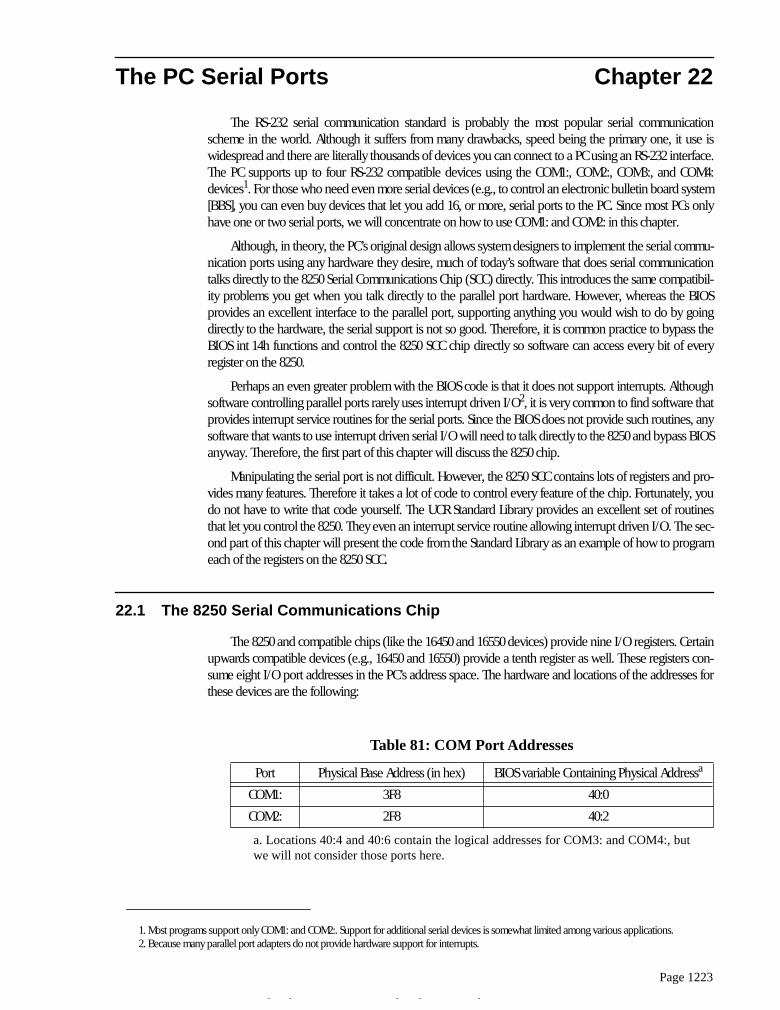
a. Locations 40:4 and 40:6 contain the logical addresses for COM3: and COM4:, butwe will not consider those ports here.
Table 81: COM Port Addresses
Port Physical Base Address (in hex) BIOS variable Containing Physical Address
a
COM1: 3F8 40:0
COM2: 2F8 40:2
Thi d t t d ith F M k 4 0 2
Chapter 22
Page 1224
Like the PC’s parallel ports, we can swap COM1: and COM2: at the software level by swapping theirbase addresses in BIOS variable 40:0 and 40:2. However, software that goes directly to the hardware, espe-cially interrupt service routines for the serial ports, needs to deal with hardware addresses, not logicaladdresses. Therefore, we will always mean I/O base address 3F8h when we discuss COM1: in this chapter.Likewise, we will always mean I/O base address 2F8h when we discuss COM2: in this chapter.
The base address is the first of eight I/O locations consumed by the 8250 SCC. The exact purpose ofthese eight I/O locations appears in the following table:
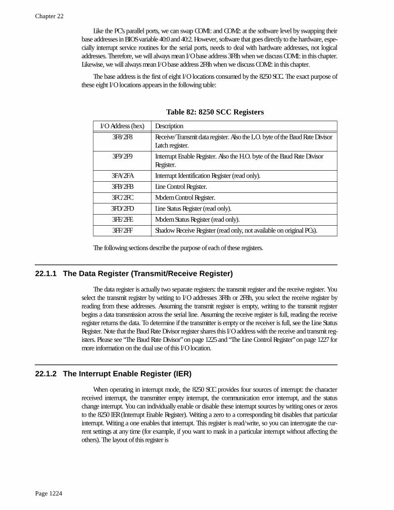
The following sections describe the purpose of each of these registers.
22.1.1 The Data Register (Transmit/Receive Register)
The data register is actually two separate registers: the transmit register and the receive register. Youselect the transmit register by writing to I/O addresses 3F8h or 2F8h, you select the receive register byreading from these addresses. Assuming the transmit register is empty, writing to the transmit registerbegins a data transmission across the serial line. Assuming the receive register is full, reading the receiveregister returns the data. To determine if the transmitter is empty or the receiver is full, see the Line StatusRegister. Note that the Baud Rate Divisor register shares this I/O address with the receive and transmit reg-isters. Please see “The Baud Rate Divisor” on page 1225 and “The Line Control Register” on page 1227 formore information on the dual use of this I/O location.
22.1.2 The Interrupt Enable Register (IER)
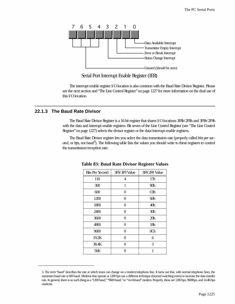
When operating in interrupt mode, the 8250 SCC provides four sources of interrupt: the characterreceived interrupt, the transmitter empty interrupt, the communication error interrupt, and the statuschange interrupt. You can individually enable or disable these interrupt sources by writing ones or zerosto the 8250 IER (Interrupt Enable Register). Writing a zero to a corresponding bit disables that particularinterrupt. Writing a one enables that interrupt. This register is read/write, so you can interrogate the cur-rent settings at any time (for example, if you want to mask in a particular interrupt without affecting theothers). The layout of this register is
Table 82: 8250 SCC Registers
I/O Address (hex) Description
3F8/2F8 Receive/Transmit data register. Also the L.O. byte of the Baud Rate Divisor Latch register.
3F9/2F9 Interrupt Enable Register. Also the H.O. byte of the Baud Rate Divisor Register.
3FA/2FA Interrupt Identification Register (read only).
3FB/2FB Line Control Register.
3FC/2FC Modem Control Register.
3FD/2FD Line Status Register (read only).
3FE/2FE Modem Status Register (read only).
3FF/2FF Shadow Receive Register (read only, not available on original PCs).
The PC Serial Ports
Page 1225
The interrupt enable register I/O location is also common with the Baud Rate Divisor Register. Pleasesee the next section and “The Line Control Register” on page 1227 for more information on the dual use ofthis I/O location.
22.1.3 The Baud Rate Divisor
The Baud Rate Divisor Register is a 16 bit register that shares I/O locations 3F8h/2F8h and 3F9h/2F9hwith the data and interrupt enable registers. Bit seven of the Line Control Register (see “The Line ControlRegister” on page 1227) selects the divisor register or the data/interrupt enable registers.
The Baud Rate Divisor register lets you select the data transmission rate (properly called
bits per sec-ond
, or
bps
, not baud
3
). The following table lists the values you should write to these registers to controlthe transmission/reception rate:
3. The term “baud” describes the rate at which tones can change on a modem/telephone line. It turns out that, with normal telephone lines, themaximum baud rate is 600 baud. Modems that operate at 1200 bps use a different technique (beyond switching tones) to increase the data transferrate. In general, there is no such thing as a “1200 baud,” “9600 baud,” or “14.4 kbaud” modem. Properly, these are 1200 bps, 9600bps, and 14.4K bpsmodems.
Table 83: Baud Rate Divisor Register Values
Bits Per Second 3F9/3F9 Value 3F8/2F8 Value
110 4 17h
300 1 80h
600 0 C0h
1200 0 60h
1800 0 40h
2400 0 30h
3600 0 20h
4800 0 18h
9600 0 0Ch
19.2K 0 6
38.4K 0 3
56K 0 1
Data Available InterruptTransmitter Empty InterruptError or Break InterruptStatus Change Interrupt
Unused (should be zero)
Serial Port Interrupt Enable Register (IER)
7 6 5 4 3 2 1 0
Chapter 22
Page 1226
You should only operate at speeds greater than 19.2K on fast PCs with high performance SCCs (e.g.,16450 or 16550). Furthermore, you should use high quality cables and keep your cables very short whenrunning at high speeds.
22.1.4 The Interrupt Identification Register (IIR)
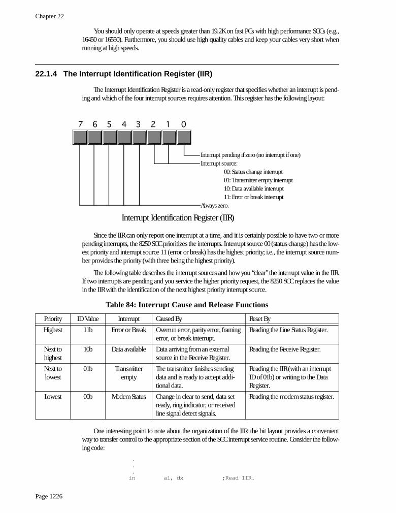
The Interrupt Identification Register is a read-only register that specifies whether an interrupt is pend-ing and which of the four interrupt sources requires attention. This register has the following layout:
Since the IIR can only report one interrupt at a time, and it is certainly possible to have two or morepending interrupts, the 8250 SCC prioritizes the interrupts. Interrupt source 00 (status change) has the low-est priority and interrupt source 11 (error or break) has the highest priority; i.e., the interrupt source num-ber provides the priority (with three being the highest priority).
The following table describes the interrupt sources and how you “clear” the interrupt value in the IIR.If two interrupts are pending and you service the higher priority request, the 8250 SCC replaces the valuein the IIR with the identification of the next highest priority interrupt source.
One interesting point to note about the organization of the IIR: the bit layout provides a convenientway to transfer control to the appropriate section of the SCC interrupt service routine. Consider the follow-ing code:
. . .in al, dx ;Read IIR.
Table 84: Interrupt Cause and Release Functions
Priority ID Value Interrupt Caused By Reset By
Highest 11b Error or Break Overrun error, parity error, framing error, or break interrupt.
Reading the Line Status Register.
Next to highest
10b Data available Data arriving from an external source in the Receive Register.
Reading the Receive Register.
Next to lowest
01b Transmitter empty
The transmitter finishes sending data and is ready to accept addi-tional data.
Reading the IIR (with an interrupt ID of 01b) or writing to the Data Register.
Lowest 00b Modem Status Change in clear to send, data set ready, ring indicator, or received line signal detect signals.
Reading the modem status register.
Interrupt pending if zero (no interrupt if one)Interrupt source: 00: Status change interrupt 01: Transmitter empty interrupt 10: Data available interrupt 11: Error or break interruptAlways zero.
Interrupt Identification Register (IIR)
7 6 5 4 3 2 1 0
The PC Serial Ports
Page 1227
mov bl, almov bh, 0jmp HandlerTbl[bx]
HandlerTbl word RLSHandler, RDHandler, TEHandler, MSHandler
When an interrupt occurs, bit zero of the IIR will be zero. The next two bits contain the interrupt sourcenumber and the H.O. five bits are all zero. This lets us use the IIR value as the index into a table of pointersto the appropriate handler routines, as the above code demonstrates.
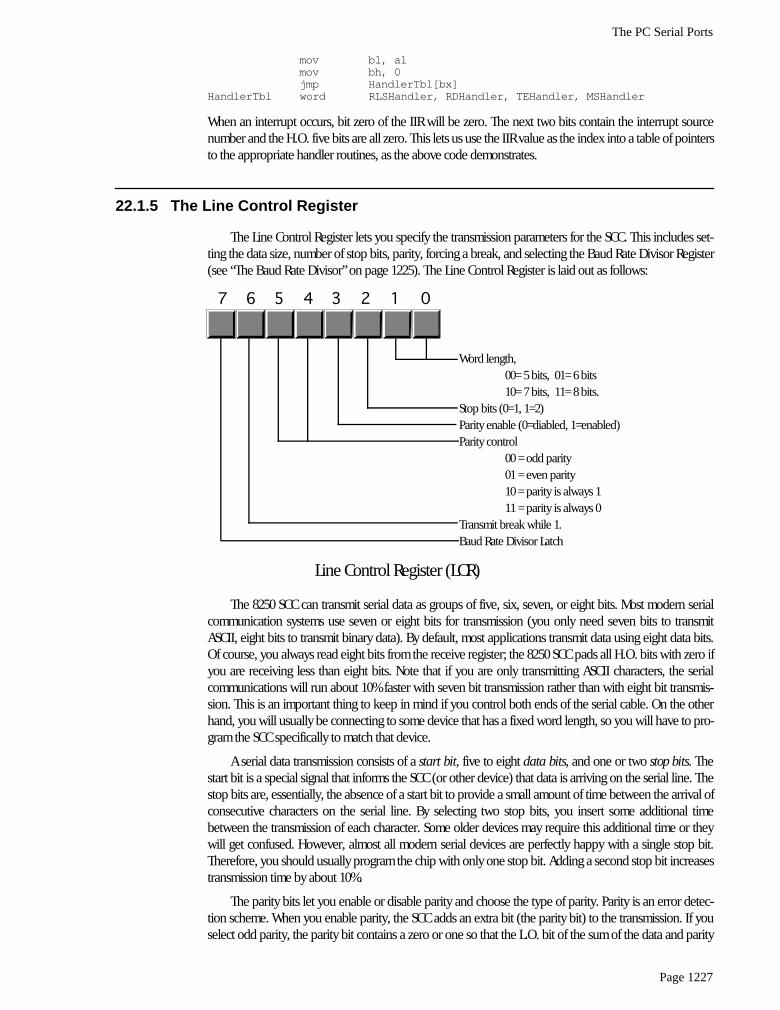
22.1.5 The Line Control Register
The Line Control Register lets you specify the transmission parameters for the SCC. This includes set-ting the data size, number of stop bits, parity, forcing a break, and selecting the Baud Rate Divisor Register(see “The Baud Rate Divisor” on page 1225). The Line Control Register is laid out as follows:
The 8250 SCC can transmit serial data as groups of five, six, seven, or eight bits. Most modern serialcommunication systems use seven or eight bits for transmission (you only need seven bits to transmitASCII, eight bits to transmit binary data). By default, most applications transmit data using eight data bits.Of course, you always read eight bits from the receive register; the 8250 SCC pads all H.O. bits with zero ifyou are receiving less than eight bits. Note that if you are only transmitting ASCII characters, the serialcommunications will run about 10% faster with seven bit transmission rather than with eight bit transmis-sion. This is an important thing to keep in mind if you control both ends of the serial cable. On the otherhand, you will usually be connecting to some device that has a fixed word length, so you will have to pro-gram the SCC specifically to match that device.
A serial data transmission consists of a
start bit
, five to eight
data bits
, and one or two
stop bits
. Thestart bit is a special signal that informs the SCC (or other device) that data is arriving on the serial line. Thestop bits are, essentially, the absence of a start bit to provide a small amount of time between the arrival ofconsecutive characters on the serial line. By selecting two stop bits, you insert some additional timebetween the transmission of each character. Some older devices may require this additional time or theywill get confused. However, almost all modern serial devices are perfectly happy with a single stop bit.Therefore, you should usually program the chip with only one stop bit. Adding a second stop bit increasestransmission time by about 10%.
The parity bits let you enable or disable parity and choose the type of parity. Parity is an error detec-tion scheme. When you enable parity, the SCC adds an extra bit (the parity bit) to the transmission. If youselect odd parity, the parity bit contains a zero or one so that the L.O. bit of the sum of the data and parity
Word length, 00= 5 bits, 01= 6 bits 10= 7 bits, 11= 8 bits.Stop bits (0=1, 1=2)Parity enable (0=diabled, 1=enabled)Parity control 00 = odd parity 01 = even parity 10 = parity is always 1 11 = parity is always 0Transmit break while 1.Baud Rate Divisor Latch
Line Control Register (LCR)
7 6 5 4 3 2 1 0

Chapter 22
Page 1228
bits is one. If you select even parity, the SCC produces a parity bit such that the L.O. bit of the sum of theparity and data bits is zero. The “stuck parity” values (10b and 11b) always produce a parity bit of zero orone. The main purpose of the parity bit is to detect a possible transmission error. If you have a long, noisy,or otherwise bad serial communications channel, it is possible to lose information during transmission.When this happens, it is unlikely that the sum of the bits will match the parity value. The receiving site candetect this “parity error” and report the error in transmission.
You can also use the stuck parity values (10b and 11b) to strip the eighth bit and always replace itwith a zero or one during transmission. For example, when transmitting eight bit PC/ASCII characters to adifferent computer system it is possible that the PC’s extended character set (those characters whose codeis 128 or greater) does not map to the same character on the destination machine. Indeed, sending suchcharacters may create problems on that machine. By setting the word size to seven bits and the parity toenabled and stuck at zero, you can automatically strip out all H.O. bits during transmission, replacing themwith zero. Of course, if any extended characters come along, the SCC will map them to possibly unrelatedASCII characters, but this is a useful trick, on occasion.
The break bit transmits a break signal to the remote system as long as there is a one programmed inthis bit position. You should not leave break enabled while trying to transmit data. The break signal comesfrom the teletype days. A break is similar to ctrl-C or ctrl-break on the PC’s keyboard. It is supposed tointerrupt a program running on a remote system. Note that the SCC can detect an incoming break signaland generate an appropriate interrupt, but this break signal is coming from the remote system, it is not(directly) connected to the outgoing break signal the LCR controls.
Bit seven of the LCR is the Baud Rate Divisor Register latch bit. When this bit contains a one, locations3F8h/2F8h and 3F9h/2F9h become the Baud Rate Divisor Register. When this bit contains a zero, thoseI/O locations correspond to the Data Registers and the Interrupt Enable Registers. You should always pro-gram this bit with a zero except while initializing the speed of the SCC.
The LCR is a read/write register. Reading the LCR returns the last value written to it.
22.1.6 The Modem Control Register
The 8250’s Modem Control Register contains five bits that let you directly control various output pinson the 8250 as well as enable the 8250’s
loopback
mode. The following diagram displays the contents ofthis register:
The 8250 routes the DTR and RTS bits directly to the DTR and RTS lines on the 8250 chip. When thesebits are one, the corresponding outputs are active
4
. These lines are two separate handshake lines forRS-232 communications.
4. It turns out that the DTR and RTS lines are active low, so the 8250 actually inverts these lines on their way out. However, the receiving site rein-verts these lines so the receiving site (if it is an 8250 SCC) will read these bits as one when they are active. See the description of the line status reg-ister for details.
Data Terminal Ready (DTR)Request To Send (RTS)OUT 1Interrupt Enable (OUT 2)Loopback mode (enabled if 1)
Always zero
Modem Control Register (MCR)
7 6 5 4 3 2 1 0

The PC Serial Ports
Page 1229
The DTR signal is comparable to a
busy
signal. When a site’s DTR line is inactive, the other site is notsupposed to transmit data to it. The DTR line is a
manual
handshake line. It appears as the Data Set Ready(DSR) line on the other side of the serial cable. The other device must explicitly check its DSR line to see ifit can transmit data. The DTR/DSR scheme is mainly intended for handshaking between computers andmodems.
The RTS line provides a second form of handshake. It’s corresponding input signal is CTS (Clear ToSend). The RTS/CTS handshake protocol is mainly intended for directly connected devices like computersand printers. You may ask “why are there two separate, but orthogonal handshake protocols?” The reasonis because RS-232C has developed over the last 100 years (from the days of the first telegraphs) and is theresult of combining several different schemes over the years.
Out1 is a general purpose output on the SCC that has very little use on the IBM PC. Some adapterboards connect this signal, other leave it disconnected. In general, this bit has no function on PCs.
The Interrupt Enable bit is a PC-specific item. This is normally a general purpose output (OUT 2) onthe 8250 SCC. However, IBM’s designers connected this output to an external gate to enable or disable allinterrupts from the SCC. This bit must be programmed with a one to enable interrupts. Likewise, you mustensure that this bit contains a zero if you are not using interrupts.
The loopback bit connects the transmitter register to the receive register. All data sent out the trans-mitter immediately comes back in the receive register. This is useful for diagnostics, testing software, anddetecting the serial chip. Note, unfortunately, that the loopback circuit will not generate any interrupts.You can only use this technique with polled I/O.
The remaining bits in the MCR are reserved should always contain zero. Future versions of the SCC(or compatible chips) may use these bits for other purposes, with zero being the default (8250 simulation)state.
The MCR is a read/write register. Reading the MCR returns the last value written to it.
22.1.7 The Line Status Register (LSR)
The Line Status Register (LSR) is a read-only register that returns the current communication status.The bit layout for this register is the following:
The data available bit is set if there is data available in the Receive Register. This also generates aninterrupt. Reading the data in the Receive Register clears this bit.
The 8250 Receive Register can only hold one byte at a time. If a byte arrives and the program does notread it and then a second byte arrives, the 8250 wipes out the first byte with the second. The 8250 SCC sets
Data Available (if 1)Overrun error (if 1)Parity error (if 1)Framing error (if 1)Break interrupt (if 1)Transmitter holding register Empty (if 1)Transmitter shift register empty (if 1)Unused
Line Status Register (LSR)
7 6 5 4 3 2 1 0

Chapter 22
Page 1230
the overrun error bit when this occurs. Reading the LSR clears this bit (after reading the LSR). This errorwill generate the high priority error interrupt.
The 8250 sets the parity bit if it detects a parity error when receiving a byte. This error only occurs ifyou have enabled the parity operation in the LCR. The 8250 resets this bit after you read the LSR. When thiserror occurs, the 8250 will generate the error interrupt.
Bit three is the framing error bit. A framing error occurs if the 8250 receives a character without a validstop bit. The 8250 will clear this bit after you read the LSR. This error will generate the high priority errorinterrupt.
The 8250 sets the break interrupt bit when it receives the break signal from the transmitting device.This will also generate an error interrupt. Reading the LSR clears this bit.
The 8250 sets bit five, the transmitter holding register empty bit, when it is okay to write another char-acter to the Data Register. Note that the 8250 actually has two registers associated with the transmitter. Thetransmitter shift register contains the data actually being shifted out over the serial line. The transmitterholding register holds a value that the 8250 writes to the shift register when it finishes shifting out a charac-ter. Bit five indicates that the holding register is empty and the 8250 can accept another byte. Note that the8250 might still be shifting out a character in parallel with this operation. The 8250 can generate an inter-rupt when the transmitter holding register is empty. Reading the LSR or writing to the Data Register clearsthis bit.
The 8250 sets bit six when both the transmitter holding and transmitter shift registers are empty. Thisbit is clear when either register contains data.
22.1.8 The Modem Status Register (MSR)
The Modem Status Register (MSR) reports the status of the handshake and other modem signals. Fourbits provide the instantaneous values of these signals, the 8250 sets the other four bits if any of these sig-nals change since the last time the CPU interrogates the MSR. The MSR has the following layout:
The Clear To Send bit (bit #4) is a handshaking signal. This is normally connected to the RTS (RequestTo Send) signal on the remove device. When that remote device asserts its RTS line, data transmission cantake place.
The Data Set Ready bit (bit #5) is one if the remote device is not busy. This input is generally con-nected to the Data Terminal Ready (DTR) line on the remote device.
The 8250 chip sets the Ring Indicator bit (bit #6) when the modem asserts the ring indicator line. Youwill rarely use this signal unless you are writing modem controlling software that automatically answers atelephone call.
Clear To Send has changed.Data Set Ready has changedTrailing edge of Ring IndicatorData Carrier Dectect has changedClear To SendData Set ReadyRing IndicatorData Carrier Detect
Modem Status Register (MSR)
7 6 5 4 3 2 1 0

The PC Serial Ports
Page 1231
The Data Carrier Detect bit (DCD, bit #7) is another modem specific signal. This bit contains a onewhile the modem detects a carrier signal on the phone line.
Bits zero through three of the MSR are the “delta” bits. These bits contain a one if their correspondingmodem status signal changes. Such an occurrence will also generate a modem status interrupt. Readingthe MSR will clear these bits.
22.1.9 The Auxiliary Input Register
The auxiliary input register is available only on later model 8250 compatible devices. This is aread-only register that returns the same value as reading the data register. The difference between readingthis register and reading the data register is that reading the auxiliary input register does not affect the dataavailable bit in the LSR. This allows you to test the incoming data value without removing it from the inputregister. This is useful, for example, when chaining serial chip interrupt service routines and you want tohandle certain “hot” values in one ISR and pass all other characters on to a different serial ISR.
22.2 The UCR Standard Library Serial Communications Support Routines
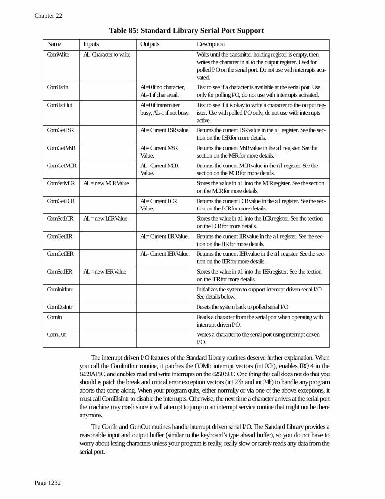
Although programming the 8250 SCC doesn’t seem like a real big problem, invariably it is a difficultchore (and tedious) to write all the software necessary to get the serial communication system working.This is especially true when using interrupt driven serial I/O. Fortunately, you do not have to write thissoftware from scratch, the UCR Standard library provides 21 support routines that trivialize the use of theserial ports on the PC. About the only drawback to these routines is that they were written specifically forCOM1:, although it isn’t too much work to modify them to work with COM2:. The following table lists theavailable routines:
Table 85: Standard Library Serial Port Support
Name Inputs Outputs Description
ComBaud AX: bps (baud rate) = 110, 150, 300, 600, 1200, 2400, 4800, 9600, or 19200
Sets the communication rate for the serial port. ComBaud only supports the specified speeds. If
ax
contains some other value on entry, ComBaud ignores the value.
ComStop AX: 1 or 2 Sets the number of stop bits. The
ax
register contains the number of stop bits to use (1 or 2).
ComSize AX: word size (5, 6, 7, or 8)
Sets the number of data bits. The
ax
register contains the number of bits to transmit for each byte on the serial line.
ComParity AX: Parity selector. If bit zero is zero, parity off, if bit zero is one, bits one and two are:00 - odd parity01 - even parity10 - parity stuck at 011 - parity stuck at 1
Sets the parity (if any) for the serial communications.
ComRead AL- Character read from port.
Waits until a character is available from in the data register and returns that character. Used for polled I/O on the serial port. Do not use if you’ve activated the serial interrupts (see ComInitIntr).
Chapter 22
Page 1232
The interrupt driven I/O features of the Standard Library routines deserve further explanation. Whenyou call the ComInitIntr routine, it patches the COM1: interrupt vectors (int 0Ch), enables IRQ 4 in the8259A PIC, and enables read and write interrupts on the 8250 SCC. One thing this call does not do that youshould is patch the break and critical error exception vectors (int 23h and int 24h) to handle any programaborts that come along. When your program quits, either normally or via one of the above exceptions, itmust call ComDisIntr to disable the interrupts. Otherwise, the next time a character arrives at the serial portthe machine may crash since it will attempt to jump to an interrupt service routine that might not be thereanymore.
The ComIn and ComOut routines handle interrupt driven serial I/O. The Standard Library provides areasonable input and output buffer (similar to the keyboard’s type ahead buffer), so you do not have toworry about losing characters unless your program is really, really slow or rarely reads any data from theserial port.
ComWrite AL- Character to write. Waits until the transmitter holding register is empty, then writes the character in al to the output register. Used for polled I/O on the serial port. Do not use with interrupts acti-vated.
ComTstIn AL=0 if no character,AL=1 if char avail.
Test to see if a character is available at the serial port. Use only for polling I/O, do not use with interrupts activated.
ComTstOut AL=0 if transmitter busy, AL=1 if not busy.
Test to see if it is okay to write a character to the output reg-ister. Use with polled I/O only, do not use with interrupts active.
ComGetLSR AL= Current LSR value. Returns the current LSR value in the
al
register. See the sec-tion on the LSR for more details.
ComGetMSR AL= Current MSR Value.
Returns the current MSR value in the
al
register. See the section on the MSR for more details.
ComGetMCR AL= Current MCR Value.
Returns the current MCR value in the
al
register. See the section on the MCR for more details.
ComSetMCR AL = new MCR Value Stores the value in
al
into the MCR register. See the section on the MCR for more details.
ComGetLCR AL= Current LCR Value.
Returns the current LCR value in the
al
register. See the sec-tion on the LCR for more details.
ComSetLCR AL = new LCR Value Stores the value in
al
into the LCR register. See the section on the LCR for more details.
ComGetIIR AL= Current IIR Value. Returns the current IIR value in the
al
register. See the sec-tion on the IIR for more details.
ComGetIER AL= Current IER Value. Returns the current IER value in the
al
register. See the sec-tion on the IER for more details.
ComSetIER AL = new IER Value Stores the value in
al
into the IER register. See the section on the IER for more details.
ComInitIntr Initializes the system to support interrupt driven serial I/O. See details below.
ComDisIntr Resets the system back to polled serial I/O
ComIn Reads a character from the serial port when operating with interrupt driven I/O.
ComOut Writes a character to the serial port using interrupt driven I/O.
Table 85: Standard Library Serial Port Support
Name Inputs Outputs Description

The PC Serial Ports
Page 1233
Between the ComInitIntr and ComDisIntr calls, you should not call any other serial support routinesexcept ComIn and ComOut. The other routines are intended for polled I/O or initialization. Obviously,you should do any necessary initialization before enabling interrupts, and there is no need to do polledI/O while the interrupts are operational. Note that there is no equivalent to ComTstIn and ComTstOutwhile operating in interrupt mode. These routines are easy to write, instructions appear in the next sec-tion.
22.3 Programming the 8250 (Examples from the Standard Library)
The UCR Standard Library Serial Communication routines provide an excellent example of how toprogram the 8250 SCC directly, since they use nearly all the features of that chip on the PC. Therefore, thissection will list each of the routines and describe exactly what that routine is doing. By studying this code,you can learn about all the details associated with the SCC and discover how to extend or otherwise mod-ify the Standard Library routines.
; Useful equates:
BIOSvars = 40h ;BIOS segment address.Com1Adrs = 0 ;Offset in BIOS vars to COM1: address.Com2Adrs = 2 ;Offset in BIOS vars to COM2: address.
BufSize = 256 ;# of bytes in buffers.
; Serial port equates. If you want to support COM2: rather than COM1:, simply; change the following equates to 2F8h, 2F9h, ...
ComPort = 3F8hComIER = 3F9hComIIR = 3FAhComLCR = 3FBhComMCR = 3FChComLSR = 3FDhComMSR = 3FEh
; Variables, etc. This code assumes that DS=CS. That is, all the variables; are in the code segment.;; Pointer to interrupt vector for int 0Ch in the interrupt vector table.; Note: change these values to 0Bh*4 and 0Bh*4 + 2 if you want to support; the COM2: pot.
int0Cofs equ es:[0Ch*4]int0Cseg equ es:[0Ch*4 + 2]
OldInt0c dword ?
; Input buffer for incoming character (interrupt operation only). See the; chapter on data structures and the description of circular queus for; details on how this buffer works. It operates in a fashion not unlike; the keyboard’s type ahead buffer.
InHead word InpBufInTail word InpBufInpBuf byte Bufsize dup (?)InpBufEnd equ this byte
; Output buffer for characters waiting to transmit.
OutHead word OutBufOutTail word OutBufOutBuf byte BufSize dup (?)OutBufEnd equ this byte
; The i8259a variable holds a copy of the PIC’s IER so we can restore it; upon removing our interrupt service routines from memory.
Chapter 22
Page 1234
i8259a byte 0 ;8259a interrupt enable register.
; The TestBuffer variable tells us whether we have to buffer up characters; or if we can store the next character directly into the 8250’s output; register (See the ComOut routine for details).
TestBuffer db 0
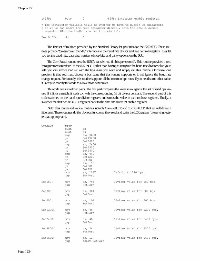
The first set of routines provided by the Standard Library let you initialize the 8250 SCC. These rou-tines provide “programmer friendly” interfaces to the baud rate divisor and line control registers. They letyou set the baud rate, data size, number of stop bits, and parity options on the SCC.
The
ComBaud
routine sets the 8250’s transfer rate (in bits per second). This routine provides a nice“programmer’s interface” to the 8250 SCC. Rather than having to compute the baud rate divisor value your-self, you can simply load
ax
with the bps value you want and simply call this routine. Of course, oneproblem is that you must choose a bps value that this routine supports or it will ignore the baud ratechange request. Fortunately, this routine supports all the common bps rates; if you need some other value,it is easy to modify this code to allow those other rates.
This code consists of two parts. The first part compares the value in ax against the set of valid bps val-ues. If it finds a match, it loads
ax
with the corresponding 16 bit divisor constant. The second part of thiscode switches on the baud rate divisor registers and stores the value in ax into these registers. Finally, itswitches the first two 8250 I/O registers back to the data and interrupt enable registers.
Note: This routine calls a few routines, notably
ComSetLCR
and
ComGetLCR
, that we will define alittle later. These routines do the obvious functions, they read and write the LCR register (preserving regis-ters, as appropriate).
ComBaud procpush axpush dxcmp ax, 9600ja Set19200je Set9600cmp ax, 2400ja Set4800je Set2400cmp ax, 600ja Set1200je Set600cmp ax, 150ja Set300je Set150mov ax, 1047 ;Default to 110 bps.jmp SetPort
Set150: mov ax, 768 ;Divisor value for 150 bps.jmp SetPort
Set300: mov ax, 384 ;Divisor value for 300 bps.jmp SetPort
Set600: mov ax, 192 ;Divisor value for 600 bps.jmp SetPort
Set1200: mov ax, 96 ;Divisor value for 1200 bps.jmp SetPort
Set2400: mov ax, 48 ;Divisor value for 2400 bps.jmp SetPort
Set4800: mov ax, 24 ;Divisor value for 4800 bps.jmp SetPort
Set9600: mov ax, 12 ;Divisor value for 9600 bps.jmp short SetPort

The PC Serial Ports
Page 1235
Set19200: mov ax, 6 ;Divisor value for 19.2 kbps.SetPort: mov dx, ax ;Save baud value.
call GetLCRCom ;Fetch LCR value.push ax ;Save old divisor bit value.or al, 80h ;Set divisor select bit.call SetLCRCom ;Write LCR value back.mov ax, dx ;Get baud rate divisor value.mov dx, ComPort ;Point at L.O. byte of divisor reg.out dx, al ;Output L.O. byte of divisor.inc dx ;Point at the H.O. byte.mov al, ah ;Put H.O. byte in AL.out dx, al ;Output H.O. byte of divisor.pop ax ;Retrieve old LCR value.call SetLCRCom1 ;Restore divisor bit value.pop dxpop axret
ComBaud endp
The
ComStop
routine programs the LCR to provide the specified number of stop bits. On entry,
ax
should contain either one or two (the number of stop bits you desire). This code converts that to zero orone and writes the resulting L.O. bit to the stop bit field of the LCR. Note that this code ignores the otherbits in the
ax
register. This code reads the LCR, masks out the stop bit field, and then inserts the value thecaller specifies into that field. Note the usage of the
shl ax, 2
instruction; this requires an 80286 or laterprocessor.
comStop procpush axpush dxdec ax ;Convert 1 or 2 to 0 or 1.and al, 1 ;Strip other bits.shl ax, 2 ;position into bit #2.mov ah, al ;Save our output value.call ComGetLCR ;Read LCR value.and al, 11111011b ;Mask out Stop Bits bit.or al, ah ;Merge in new # of stop bits.call ComSetLCR ;Write result back to LCR.pop dxpop axret
comStop endp
The
ComSize
routine sets the word size for data transmission. As usual, this code provides a “pro-grammer friendly” interface to the 8250 SCC. On enter, you specify the number of bits (5, 6, 7, or 8) in the
ax
register, you do not have to worry an appropriate bit pattern for the 8250’s LCR register. This routinewill compute the appropriate bit pattern for you. If the value in the ax register is not appropriate, this codedefaults to an eight bit word size.
ComSize procpush axpush dxsub al, 5 ;Map 5..8 -> 00b, 01b, 10b, 11bcmp al, 3jbe Okaymov al, 3 ;Default to eight bits.
Okay: mov ah, al ;Save new bit size.call ComGetLCR ;Read current LCR value.and al, 11111100b ;Mask out old word size.or al, ah ;Merge in new word size.call ComSetLCR ;Write new LCR value back.pop dxpop axret
comsize endp

Chapter 22
Page 1236
The ComParity routine initializes the parity options on the 8250. Unfortunately, there is little possibil-ity of a “programmer friendly” interface to this routine, So this code requires that you pass one of the fol-lowing values in the
ax
register:
comparity procpush axpush dx
shl al, 3 ;Move to final position in LCR.and al, 00111000b ;Mask out other data.mov ah, al ;Save for later.call ComGetLCR ;Get current LCR value.and al, 11000111b ;Mask out existing parity bits.or al, ah ;Merge in new bits.call ComSetLCR ;Write results back to the LCR.pop dxpop axret
comparity endp
The next set of serial communication routines provide polled I/O support. These routines let you eas-ily read characters from the serial port, write characters to the serial port, and check to see if there is dataavailable at the input port or see if it is okay to write data to the output port.
Under no circumstancesshould you use these routines when you’ve activated the serial interrupt system.
Doing so may confuse thesystem and produce incorrect data or loss of data.
The
ComRead
routine is comparable to
getc
– it waits until data is available at the serial port, readsthat data, and returns it in the
al
register. This routine begins by making sure we can access the ReceiveData register (by clearing the baud rate divisor latch bit in the LCR).
ComRead procpush dxcall GetLCRCompush ax ;Save divisor latch access bit.and al, 7fh ;Select normal ports.call SetLCRCom ;Write LCR to turn off divisor reg.
WaitForChar: call GetLSRCom ;Get data available bit from LSR.test al, 1 ;Data Available?jz WaitForChar ;Loop until data available.mov dx, comPort ;Read the data from the input port.in al, dxmov dl, al ;Save characterpop ax ;Restore divisor access bit.call SetLCRCom ;Write it back to LCR.mov al, dl ;Restore output character.pop dxret
Table 86: ComParity Input Parameters
Value in AX Description
0 Disable parity.
1 Enable odd parity checking.
3 Enable even parity checking.
5 Enable stuck parity bit with value one.
7 Enable stuck parity bit with value zero.

The PC Serial Ports
Page 1237
ComRead endp
The
ComWrite
routine outputs the character in al to the serial port. It first waits until the transmitterholding register is empty, then it writes the output data to the output register.
ComWrite procpush dxpush axmov dl, al ;Save character to outputcall GetLCRCom ;Switch to output register.push ax ;Save divisor latch access bit.and al, 7fh ;Select normal input/output portscall SetLCRCom ; rather than divisor register.
WaitForXmtr: call GetLSRCom ;Read LSR for xmit empty bit.test al, 00100000b ;Xmtr buffer empty?jz WaitForXmtr ;Loop until empty.mov al, dl ;Get output character.mov dx, ComPort ;Store it in the ouput port toout dx, al ; get it on its way.pop ax ;Restore divisor access bit.call SetLCRCompop axpop dxret
ComWrite endp
The
ComTstIn
and
ComTstOut
routines let you check to see if a character is available at the inputport (
ComTstIn
) or if it is okay to send a character to the output port (
ComTstOut
).
ComTstIn
returnszero or one in
al
if data is not available or is available, respectively.
ComTstOut
returns zero or one in
al
if the transmitter register is full or empty, respectively.
ComTstIn proccall GetComLSRand ax, 1 ;Keep only data available bit.ret
ComTstIn endp
ComTstOut procpush dxcall ComGetLSR ;Get the line status.test al, 00100000b ;Mask Xmitr empty bit.mov al, 0 ;Assume not empty.jz toc1 ;Branch if not empty.inc ax ;Set to one if it is empty.
toc1: retComTstOut endp
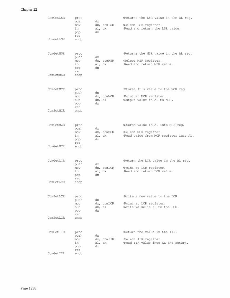
The next set of routines the Standard Library supplies load and store the various registers on the 8250SCC. Although these are all trivial routines, they allow the programmer to access these register by namewithout having to know the address. Furthermore, these routines all preserve the value in the
dx
register,saving some code in the calling program if the
dx
register is already in use.
The following routines let you read (“Get”) the value in the LSR, MSR, LCR, MCR, IIR, and IER regis-ters, returning said value in the
al
register. They let you write (“Set”) the value in
al
to any of the LCR,MCR, and IER registers. Since these routines are so simple and straight-forward, there is no need to discusseach routine individually. Note that you should avoid calling these routines outside an SCC ISR while ininterrupt mode, since doing so can affect the interrupt system on the 8250 SCC.
Chapter 22
Page 1238
ComGetLSR proc ;Returns the LSR value in the AL reg.push dxmov dx, comLSR ;Select LSR register.in al, dx ;Read and return the LSR value.pop dxret
ComGetLSR endp
ComGetMSR proc ;Returns the MSR value in the AL reg.push dxmov dx, comMSR ;Select MSR register.in al, dx ;Read and return MSR value.pop dxret
ComGetMSR endp
ComSetMCR proc ;Stores AL’s value to the MCR reg.push dxmov dx, comMCR ;Point at MCR register.out dx, al ;Output value in AL to MCR.pop dxret
ComSetMCR endp
ComGetMCR proc ;Stores value in AL into MCR reg.push dxmov dx, comMCR ;Select MCR register.in al, dx ;Read value from MCR register into AL.pop dxret
ComGetMCR endp
ComGetLCR proc ;Return the LCR value in the AL reg.push dxmov dx, comLCR ;Point at LCR register.in al, dx ;Read and return LCR value.pop dxret
ComGetLCR endp
ComSetLCR proc ;Write a new value to the LCR.push dxmov dx, comLCR ;Point at LCR register.out dx, al ;Write value in AL to the LCR.pop dxret
ComSetLCR endp
ComGetIIR proc ;Return the value in the IIR.push dxmov dx, comIIR ;Select IIR register.in al, dx ;Read IIR value into AL and return.pop dxret
ComGetIIR endp

The PC Serial Ports
Page 1239
ComGetIER proc ;Return IER value in AL.push dxcall ComGetLCR ;Need to select IER register by savingpush ax ; the LCR value and then clearing theand al, 7fh ; baud rate divisor latch bit.call ComSetLCRmov dx, comIER ;Address the IER.in al, dx ;Read current IER value.mov dl, al ;Save for nowpop ax ;Retrieve old LCR value (divisor latch).call ComSetLCR ;Restore divisor latchmov al, dl ;Restore IER valuepop dxret
ComGetIER endp
ComSetIER proc ;Writes value in AL to the IER.push dxpush ax ;Save AX’s value.mov ah, al ;Save IER value to output.call ComGetLCR ;Get and save divsor accesspush ax ; bit.and al, 7fh ;Clear divisor access bit.call ComSetLCRmov al, ah ;Retrieve new IER value.mov dx, comIER ;Select IER registerout dx, al ;Output IER value.pop ax ;Restore divisor latch bit.call ComSetLCRpop axpop dxret
ComSetIER endp
The last set of serial support routines appearing in the Standard Library provide support for interruptdriven I/O. There are five routines in this section of the code:
ComInitIntr
,
ComDisIntr
,
Com-IntISR
, ComIn, and ComOut. The ComInitIntr initializes the serial port interrupt system. It saves theold int 0Ch interrupt vector, initializes the vector to point at the ComIntISR interrupt service routine, andproperly initializes the 8259A PIC and 8250 SCC for interrupt based operation. ComDisIntr undoeseverything the ComDisIntr routine sets up; you need to call this routine to disable interrupts beforeyour program quits. ComOut and ComIn transfer data to and from the buffers described in the variablessection; the ComIntISR routine is responsible for removing data from the transmit queue and sendingover the serial line as well as buffering up incoming data from the serial line.
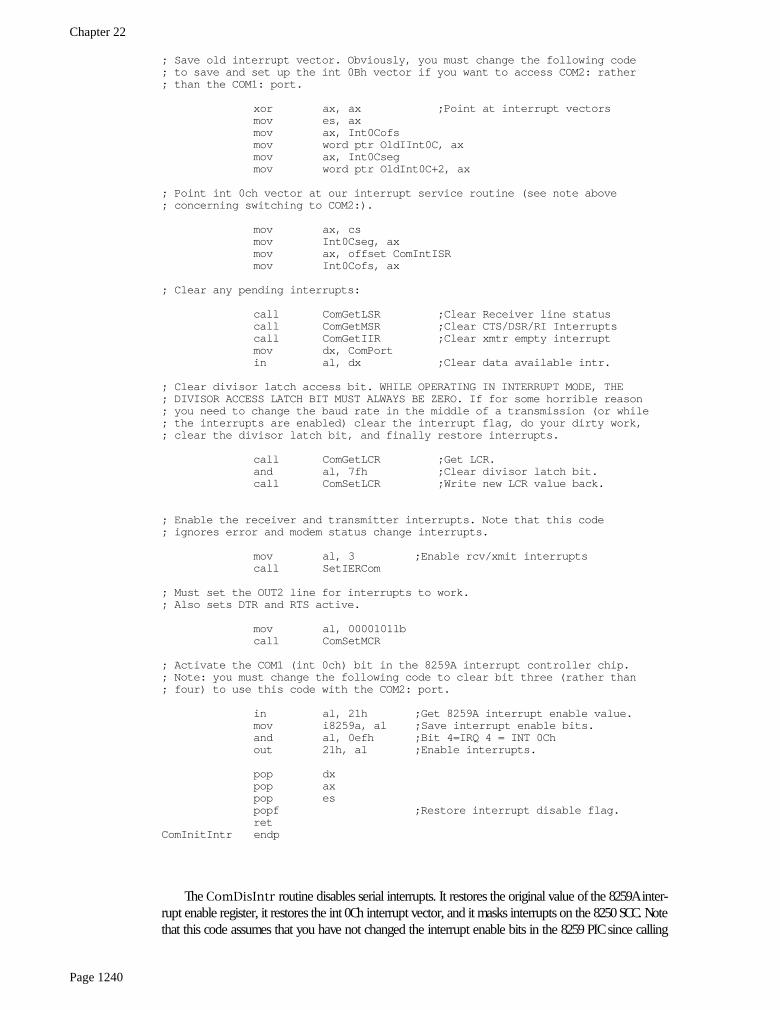
The ComInitIntr routine initializes the 8250 SCC and 8259A PIC for interrupt based serial I/O. Italso initializes the int 0Ch vector to point at the ComIntISR routine. One thing this code does not do is toprovide break and critical error exception handlers. Remember, if the user hits ctrl-C (or ctrl-Break) orselects abort on an I/O error, the default exception handlers simply return to DOS without restoring theint 0Ch vector. It is important that your program provide exception handlers that will call ComDisIntrbefore allowing the system to return control to DOS. Otherwise the system may crash when DOS loads thenext program into memory. See “Interrupts, Traps, and Exceptions” on page 995 for more details on writ-ing these exception handlers.
ComInitIntr procpushf ;Save interrupt disable flag.push espush axpush dx
; Turn off the interrupts while we’re doing this.
cli
Chapter 22
Page 1240
; Save old interrupt vector. Obviously, you must change the following code; to save and set up the int 0Bh vector if you want to access COM2: rather; than the COM1: port.
xor ax, ax ;Point at interrupt vectorsmov es, axmov ax, Int0Cofsmov word ptr OldIInt0C, axmov ax, Int0Csegmov word ptr OldInt0C+2, ax
; Point int 0ch vector at our interrupt service routine (see note above; concerning switching to COM2:).
mov ax, csmov Int0Cseg, axmov ax, offset ComIntISRmov Int0Cofs, ax
; Clear any pending interrupts:
call ComGetLSR ;Clear Receiver line statuscall ComGetMSR ;Clear CTS/DSR/RI Interruptscall ComGetIIR ;Clear xmtr empty interruptmov dx, ComPortin al, dx ;Clear data available intr.
; Clear divisor latch access bit. WHILE OPERATING IN INTERRUPT MODE, THE; DIVISOR ACCESS LATCH BIT MUST ALWAYS BE ZERO. If for some horrible reason; you need to change the baud rate in the middle of a transmission (or while; the interrupts are enabled) clear the interrupt flag, do your dirty work,; clear the divisor latch bit, and finally restore interrupts.
call ComGetLCR ;Get LCR.and al, 7fh ;Clear divisor latch bit.call ComSetLCR ;Write new LCR value back.
; Enable the receiver and transmitter interrupts. Note that this code; ignores error and modem status change interrupts.
mov al, 3 ;Enable rcv/xmit interruptscall SetIERCom
; Must set the OUT2 line for interrupts to work.; Also sets DTR and RTS active.
mov al, 00001011bcall ComSetMCR
; Activate the COM1 (int 0ch) bit in the 8259A interrupt controller chip.; Note: you must change the following code to clear bit three (rather than; four) to use this code with the COM2: port.
in al, 21h ;Get 8259A interrupt enable value.mov i8259a, al ;Save interrupt enable bits.and al, 0efh ;Bit 4=IRQ 4 = INT 0Chout 21h, al ;Enable interrupts.
pop dxpop axpop espopf ;Restore interrupt disable flag.ret
ComInitIntr endp
The ComDisIntr routine disables serial interrupts. It restores the original value of the 8259A inter-rupt enable register, it restores the int 0Ch interrupt vector, and it masks interrupts on the 8250 SCC. Notethat this code assumes that you have not changed the interrupt enable bits in the 8259 PIC since calling

The PC Serial Ports
Page 1241
ComInitIntr. It restores the 8259A’s interrupt enable register with the value from the 8259A interruptenable register when you originally called ComInitIntr.
It would be a complete disaster to call this routine without first calling ComInitIntr. Doing sowould patch the int 0Ch vector with garbage and, likewise, restore the 8259A interrupt enable register witha garbage value. Make sure you’ve called ComInitIntr before calling this routine. Generally, you shouldcall ComInitIntr once, at the beginning of your program, and call ComDisIntr once, either at the endof your program or within the break or critical error exception routines.
ComDisIntr procpushfpush espush dxpush ax
cli ;Don’t allow interrupts while messingxor ax, ax ; with the interrupt vectors.mov es, ax ;Point ES at interrupt vector table.
; First, turn off the interrupt source at the 8250 chip:
call ComGetMCR ;Get the OUT 2 (interrupt enable) bit.and al, 3 ;Mask out OUT 2 bit (masks ints)call ComSetMCR ;Write result to MCR.
; Now restore the IRQ 4 bit in the 8259A PIC. Note that you must modify this; code to restore the IRQ 3 bit if you want to support COM2: instead of COM1:
in al, 21h ;Get current 8259a IER valueand al, 0efh ;Clear IRQ 4 bit (change for COM2:!)mov ah, i8259a ;Get our saved valueand ah, 1000b ;Mask out com1: bit (IRQ 4).or al, ah ;Put bit back in.out 21h, al
; Restore the interrupt vector:
mov ax, word ptr OldInt0Cmov Int0Cofs, axmov ax, word ptr OldInt0C+2mov Int0Cseg, ax
pop axpop dxpop espopfret
ComDisIntr endp
The following code implements the interrupt service routine for the 8250 SCC. When an interruptoccurs, this code reads the 8250 IIR to determine the source of the interrupt. The Standard Library routinesonly provide direct support for data available interrupts and transmitter holding register empty interrupts.If this code detects an error or status change interrupt, it clears the interrupt status but takes no otheraction. If it detects a receive or transmit interrupt, it transfers control to the appropriate handler.
The receiver interrupt handler is very easy to implement. All this code needs to do is read the charac-ter from the Receive Register and add this character to the input buffer. The only catch is that this codemust ignore any incoming characters if the input buffer is full. An application can access this data using theComIn routine that removes data from the input buffer.
The transmit handler is somewhat more complex. The 8250 SCC interrupts the 80x86 when it is ableto accept more data for transmission. However, the fact that the 8250 is ready for more data doesn’t guar-antee there is data ready for transmission. The application produces data at its own rate, not necessarily atthe rate that 8250 SCC wants it. Therefore, it is quite possible for the 8250 to say “give me more data” but

Chapter 22
Page 1242
the application has not produced any. Obviously, we should not transmit anything at that point. Instead,we have to wait for the application to produce more data before transmission resumes.
Unfortunately, this complicates the driver for the transmission code somewhat. With the receiver, theinterrupt always indicates that the ISR can move data from the 8250 to the buffer. The application canremove this data at any time and the process is always the same: wait for a non-empty receive buffer andthen remove the first item from the buffer. Unfortunately, we cannot simply do the converse operationwhen transmitting data. That is, we can’t simply store data in the transmit buffer and leave it up to the ISRto remove this data. The problem is that the 8250 only interrupts the system once when the transmitterholding register is empty. If there is no data to transmit at that point, the ISR must return without writinganything to the transmit register. Since there is no data in the transmit buffer, there will be no additionaltransmitter interrupts generated, even when there is data added to the transmit buffer. Therefore, the ISRand the routine responsible for adding data to the output buffer (ComOut) must coordinate their activi-ties. If the buffer is empty and the transmitter is not currently transmitting anything, the ComOut routinemust write its data directly to the 8250. If the 8250 is currently transmitting data, ComOut must append itsdata to the end of the output buffer. The ComIntISR and ComOut use a flag, TestBuffer, to determinewhether ComOut should write directly to the serial port or append its data to the output buffer. See thefollowing code and the code for ComOut for all the details.
ComIntISR proc farpush axpush bxpush dx
TryAnother: mov dx, ComIIRin al, dx ;Get interrupt id value.test al, 1 ;Any interrupts left?jnz IntRtn ;Quit if no interrupt pending.cmp al, 100b ;Since only xmit/rcv ints arejnz ReadCom1 ; active, this checks for rcv int.cmp al, 10b ;This checks for xmit empty intr.jnz WriteCom1
; Bogus interrupt? We shouldn’t ever fall into this code because we have; not enabled the error or status change interrupts. However, it is possible; that the application code has gone in and tweakd the IER on the 8250.; Therefore, we need to supply a default interrupt handler for these conditions.; The following code just reads all the appropriate registers to clear any; pending interrupts.
call ComGetLSR ;Clear receiver line statuscall ComGetMSR ;Clear modem status.jmp TryAnother ;Check for lower priority intr.
; When there are no more pending interrupts on the 8250, drop down and; and return from this ISR.
IntRtn: mov al, 20h ;Acknowledge interrupt to theout 20h, al ; 8259A interrupt controller.pop dxpop bxpop axiret
; Handle incoming data here:; (Warning: This is a critical region. Interrupts MUST BE OFF while executing; this code. By default, interrupts are off in an ISR. DO NOT TURN THEM ON; if you modify this code).
ReadCom1: mov dx, ComPort ;Point at data input register.in al, dx ;Get the input char
mov bx, InHead ;Insert the character into themov [bx], al ; serial input buffer.
inc bx ;Increment buffer ptr.cmp bx, offset InpBufEndjb NoInpWrap
The PC Serial Ports
Page 1243
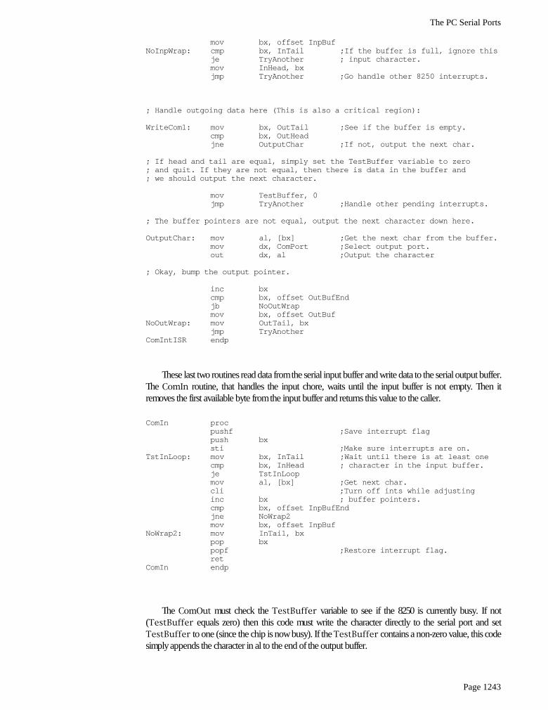
mov bx, offset InpBufNoInpWrap: cmp bx, InTail ;If the buffer is full, ignore this
je TryAnother ; input character.mov InHead, bxjmp TryAnother ;Go handle other 8250 interrupts.
; Handle outgoing data here (This is also a critical region):
WriteCom1: mov bx, OutTail ;See if the buffer is empty.cmp bx, OutHeadjne OutputChar ;If not, output the next char.
; If head and tail are equal, simply set the TestBuffer variable to zero; and quit. If they are not equal, then there is data in the buffer and; we should output the next character.
mov TestBuffer, 0jmp TryAnother ;Handle other pending interrupts.
; The buffer pointers are not equal, output the next character down here.
OutputChar: mov al, [bx] ;Get the next char from the buffer.mov dx, ComPort ;Select output port.out dx, al ;Output the character
; Okay, bump the output pointer.
inc bxcmp bx, offset OutBufEndjb NoOutWrapmov bx, offset OutBuf
NoOutWrap: mov OutTail, bxjmp TryAnother
ComIntISR endp
These last two routines read data from the serial input buffer and write data to the serial output buffer.The ComIn routine, that handles the input chore, waits until the input buffer is not empty. Then itremoves the first available byte from the input buffer and returns this value to the caller.
ComIn procpushf ;Save interrupt flagpush bxsti ;Make sure interrupts are on.
TstInLoop: mov bx, InTail ;Wait until there is at least onecmp bx, InHead ; character in the input buffer.je TstInLoopmov al, [bx] ;Get next char.cli ;Turn off ints while adjustinginc bx ; buffer pointers.cmp bx, offset InpBufEndjne NoWrap2mov bx, offset InpBuf
NoWrap2: mov InTail, bxpop bxpopf ;Restore interrupt flag.ret
ComIn endp
The ComOut must check the TestBuffer variable to see if the 8250 is currently busy. If not(TestBuffer equals zero) then this code must write the character directly to the serial port and setTestBuffer to one (since the chip is now busy). If the TestBuffer contains a non-zero value, this codesimply appends the character in al to the end of the output buffer.

Chapter 22
Page 1244
ComOut proc farpushfcli ;No interrupts now!cmp TestBuffer, 0 ;Write directly to serial chip?jnz BufferItUp ;If not, go put it in the buffer.
; The following code writes the current character directly to the serial port; because the 8250 is not transmitting anything now and we will never again; get a transmit holding register empty interrupt (at least, not until we; write data directly to the port).
push dxmov dx, ComPort ;Select output register.out dx, al ;Write character to port.mov TestBuffer, 1 ;Must buffer up next char.pop dxpopf ;Restore interrupt flag.ret
; If the 8250 is busy, buffer up the character here:
BufferItUp: push bxmov bx, OutHead ;Pointer to next buffer position.mov [bx], al ;Add the char to the buffer.
; Bump the output pointer.
inc bxcmp bx, offset OutBufEndjne NoWrap3mov bx, offset OutBuf
NoWrap3: cmp bx, OutTail ;See if the buffer is full.je NoSetTail ;Don’t add char if buffer is full.mov OutHead, bx ;Else, update buffer ptr.
NoSetTail: pop bxpopf ;Restore interrupt flagret
ComOut endp
Note that the Standard Library does not provide any routines to see if there is data available in theinput buffer or to see if the output buffer is full (comparable to the ComTstIn and ComTstOut routines).However, these are very easy routines to write; all you need do is compare the head and tail pointers ofthe two buffers. The buffers are empty if the head and tail pointers are equal. The buffers are full if thehead pointer is one byte before the tail pointer (keep in mind, the pointers wrap around at the end of thebuffer, so the buffer is also full if the head pointer is at the last position in the buffer and the tail pointer isat the first position in the buffer).
22.4 Summary
This chapter discusses RS-232C serial communications on the PC. Like the parallel port, there arethree levels at which you can access the serial port: through DOS, through BIOS, or by programming thehardware directly. Unlike DOS’ and BIOS’ parallel printer support, the DOS serial support is almost worth-less and the BIOS support is rather weak (e.g., it doesn’t support interrupt driven I/O). Therefore, it iscommon programming practice on the PC to control the hardware directly from an application program.Therefore, familiarizing one’s self with the 8250 Serial Communication Chip (SCC) is important if youintend to do serial communications on the PC. This chapter does not discuss serial communication fromDOS or BIOS, mainly because their support is so limited. For further information on programming theserial port from DOS or BIOS, see “MS-DOS, PC-BIOS, and File I/O” on page 699.
The 8250 supports ten I/O registers that let you control the communication parameters, check the sta-tus of the chip, control interrupt capabilities, and, of course, perform serial I/O. the 8250 maps these regis-ters to eight I/O locations in the PC’s I/O address space.

The PC Serial Ports
Page 1245
The PC supports up to four serial communication devices: COM1:, COM2:, COM3:, and COM4:. How-ever, most software only deals with the COM1: and COM2: ports. Like the parallel port support, BIOS dif-ferentiates logical communication ports and physical communication ports. BIOS stores the base addressof COM1:..COM4: in memory locations 40:0, 40:2, 40:4, and 40:6. This base address is the I/O address ofthe first 8250 register for that particular communication port. For more information on the 8250 hardware,check out
• “The 8250 Serial Communications Chip” on page 1223• “The Data Register (Transmit/Receive Register)” on page 1224• “The Interrupt Enable Register (IER)” on page 1224• “The Baud Rate Divisor” on page 1225• “The Interrupt Identification Register (IIR)” on page 1226• “The Line Control Register” on page 1227• “The Modem Control Register” on page 1228• “The Line Status Register (LSR)” on page 1229• “The Modem Status Register (MSR)” on page 1230• “The Auxiliary Input Register” on page 1231
The UCR Standard Library provides a very reasonable set of routines you can use to control the serialport on the PC. Not only does this package provide a set of polling routines you can use much like theBIOS’ code, but it also provides an interrupt service routine to support interrupt driven I/O on the serialport. For more information on these routines, see
• “The UCR Standard Library Serial Communications Support Routines” on page 1231
The Standard Library serial I/O routines provide an excellent example of how to program the 8250SCC. Therefore, this chapter concludes by presenting and explaining the Standard Library’s serial I/O rou-tines. In particular, this code demonstrates some of the subtle problems with interrupt driven serial com-munication. For all the details, read
• “Programming the 8250 (Examples from the Standard Library)” on page 1233

Chapter 22
Page 1246