the oxide fluoride chemistry of bromine, selenium and · pdf filethe oxide fluoride chemistry...
TRANSCRIPT
The Oxide Fluoride Chemistry of Bromine, Selenium and Sulphur
Thesis submitted for the degree of
Doctor o f Philosophy
at the
University of Leicester
by
LEE JO H N W O O TTO N
Department o
Faculty o f
University o
1997
UMI Number: U095961
All rights reserved
INFORMATION TO ALL USERS The quality of this reproduction is dependent upon the quality of the copy submitted.
In the unlikely event that the author did not send a complete manuscript and there are missing pages, these will be noted. Also, if material had to be removed,
a note will indicate the deletion.
Dissertation Publishing
UMI U095961Published by ProQuest LLC 2013. Copyright in the Dissertation held by the Author.
Microform Edition © ProQuest LLC.All rights reserved. This work is protected against
unauthorized copying under Title 17, United States Code.
ProQuest LLC 789 East Eisenhower Parkway
P.O. Box 1346 Ann Arbor, Ml 48106-1346
STATEMENT
The experimental work described in this thesis has been carried out by
the author in the Department of Chemistry at the University of Leicester
between October 1993 and September 1996. The work has not been submitted,
and is not presently being submitted, for any other degree at this or any other
university.
Department of Chemistry
University of Leicester
University Road
Leicester
U.K.
L E I7R H
i
Abstract
The Oxide Fluoride Chemistry of Bromine, Selenium and Sulphur
Lee J. Wootton
The transition metal carbonyls [Re2 (CO)10], [Mn2 (CO)10] and[Ru(CO)3 (PPh3)2], and elemental iodine have been reacted with Xe(OSeF5)2. The products have been fully characterised by a combination of mass spectrometry, infrared spectroscopy, 1 9 F, 13C and 3 1 P{ 1 H} (where appropriate) NMR spectroscopies. Further characterisation of the novel compounds Xe(OSeF5)2, [Re(CO)5 (OSeF5)] and [Mn(CO)5 (OSeF5)] by EXAFS spectroscopy is reported.
An extensive review of the halogen oxide fluorides has been carried out and attempts were made to synthesise a range of fluorides and oxide fluorides of bromine. The bromine fluorides [BrF2 ][AsF6], [BrF4 ][Sb 2 F u ] , K[BrF4] and Cs[BrF6] were successfully characterised using EXAFS spectroscopy. The compound Cs[BrOF4] has been synthesised and the application of EXAFS spectroscopy has yielded internal bond parameters.
The area of fluorosulphate chemistry has been reviewed and reactions have been carried out between the superacid H S 03F and a range of transition metal carbonyl complexes and Ti, Hf and Zr derivatives. The complexes produced were characterised using mass spectrometry, infrared spectroscopy and 1 H, 1 3 C, 1 3 C{ 1 H} and 19F NMR spectroscopies. The protonation of the carbonyl clusters [Ir4 (CO)12], [Os3 (CO)12] and [Ru3 (CO)12] by H S 0 3F was investigated. The systems were found to be the same as those previously observed for the superacid AHF.
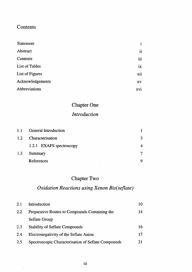
Contents
Statement i
Abstract ii
Contents iii
List of Tables ix
List of Figures xii
Acknowledgements xv
Abbreviations xvi
Chapter One
Introduction
1.1 General Introduction 1
1.2 Characterisation 3
1.2.1 EXAFS spectroscopy 4
1.3 Summary 7
References 9
Chapter Two
Oxidation Reactions using Xenon Bis(seflate)
2.1 Introduction 10
2.2 Preparative Routes to Compounds Containing the 14
Seflate Group
2.3 Stability of Seflate Compounds 16
2.4 Electronegativity of the Seflate Anion 17
2.5 Spectroscopic Characterisation of Seflate Compounds 21
iii
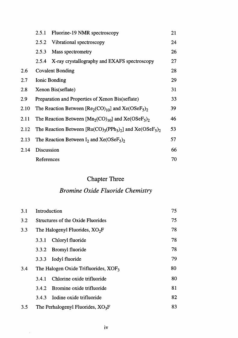
2.5.1 Fluorine-19 NMR spectroscopy 2 1
2.5.2 Vibrational spectroscopy 24
2.5.3 Mass spectrometry 26
2.5.4 X-ray crystallography and EXAFS spectroscopy 27
2 . 6 Covalent Bonding 28
2.7 Ionic Bonding 29
2 . 8 Xenon Bis(seflate) 31
2.9 Preparation and Properties of Xenon Bis(seflate) 33
2 . 1 0 The Reaction Between [Re2 (CO)10] and Xe(OSeF5 ) 2 39
2 . 1 1 The Reaction Between [Mn2 (CO)10] and Xe(OSeF5 ) 2 46
2 . 1 2 The Reaction Between [Ru(CO)3 (PPh3)2] and Xe(OSeF5 ) 2 53
2.13 The Reaction Between I2 and Xe(OSeF5 ) 2 57
2.14 Discussion 6 6
References
Chapter Three
Bromine Oxide Fluoride Chemistry
70
3.1 Introduction 75
3.2 Structures of the Oxide Fluorides 75
3.3 The Halogenyl Fluorides, X 0 2F 78
3.3.1 Chlory 1 fluoride 78
3.3.2 Bromyl fluoride 78
3.3.3 Iodyl fluoride 79
3.4 The Halogen Oxide Trifluorides, XOF3 80
3.4.1 Chlorine oxide trifluoride 80
3.4.2 Bromine oxide trifluoride 81
3.4.3 Iodine oxide trifluoride 82
3.5 The Perhalogenyl Fluorides, X 0 3F 83
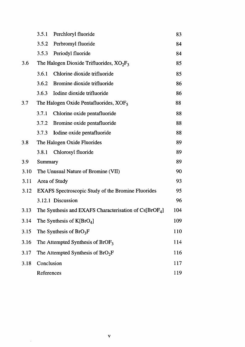
3.5.1 Perchloryl fluoride 83
3.5.2 Perbromyl fluoride 84
3.5.3 Periodyl fluoride 84
3.6 The Halogen Dioxide Trifluorides, X 0 2 F3 85
3.6.1 Chlorine dioxide trifluoride 85
3.6.2 Bromine dioxide trifluoride 8 6
3.6.3 Iodine dioxide trifluoride 8 6
3.7 The Halogen Oxide Pentafluorides, XOF5 8 8
3.7.1 Chlorine oxide pentafluoride 8 8
3.7.2 Bromine oxide pentafluoride 8 8
3.7.3 Iodine oxide pentafluoride 8 8
3.8 The Halogen Oxide Fluorides 89
3.8.1 Chlorosyl fluoride 89
3.9 Summary 89
3.10 The Unusual Nature of Bromine (VII) 90
3.11 Area of Study 93
3.12 EXAFS Spectroscopic Study of the Bromine Fluorides 95
3.12.1 Discussion 96
3.13 The Synthesis and EXAFS Characterisation of Cs[BrOF4] 104
3.14 The Synthesis of K[Br04] 109
3.15 The Synthesis of B r0 3F 110
3.16 The Attempted Synthesis of BrOF3 114
3.17 The Attempted Synthesis of B r0 2F 116
3.18 Conclusion 117
References 119
v
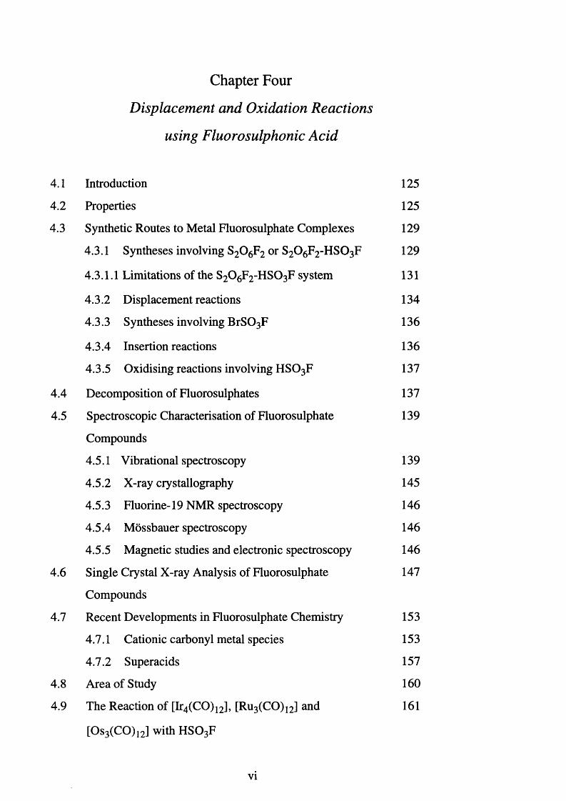
Chapter Four
Displacement and Oxidation Reactions
using Fluorosulphonic Acid
4.1 Introduction 125
4.2 Properties 125
4.3 Synthetic Routes to Metal Fluorosulphate Complexes 129
4.3.1 Syntheses involving S2 0 6 F2 or S2 0 6 F2 -H S 03F 129
4.3.1.1 Limitations of the S2 0 6 F 2 -H S 03F system 131
4.3.2 Displacement reactions 134
4.3.3 Syntheses involving B rS03F 136
4.3.4 Insertion reactions 136
4.3.5 Oxidising reactions involving H S 03F 137
4.4 Decomposition of Fluorosulphates 137
4.5 Spectroscopic Characterisation of Fluorosulphate 139
Compounds
4.5.1 Vibrational spectroscopy 139
4.5.2 X-ray crystallography 145
4.5.3 Fluorine-19 NMR spectroscopy 146
4.5.4 Mossbauer spectroscopy 146
4.5.5 Magnetic studies and electronic spectroscopy 146
4.6 Single Crystal X-ray Analysis of Fluorosulphate 147
Compounds
4.7 Recent Developments in Fluorosulphate Chemistry 153
4.7.1 Cationic carbonyl metal species 153
4.7.2 Superacids 157
4.8 Area of Study 160
4.9 The Reaction of [Ir4 (CO)12], [Ru3 (CO)12] and 161
[Os3 (CO)12] with H S 03F
vi
4.9.1 Summary 164
4.10 The Reaction Between [Fe2 (CO)10] and H S 03F 166
4.11 The Reaction Between Re or Mn Carbonyl 168
Derivatives and H S 03F
4.12 The Reaction Between [Cp2 MX2] (M = Ti, Zr or 172
Hf and X = Me or Cl) and H S 03F
4.13 The Reaction Between [W(CO)6] and H S 03F 177
4.14 The Reaction Between [Mo(CO)6] and H S 03F 178
4.15 The Reaction Between [Co2 (CO)8] or [Cr(CO)6] 179
and HSO 3 F
4.16 Summary 180
References 181
Chapter Five
Experimental
5.1 Handling of Materials 186
5.1.1 Metal vacuum line 186
5.1.2 Inert atmosphere dry box 186
5.2 Reaction Vessels 188
5.2.1 Metal reactors 188
5.2.2 Glass apparatus 188
5.2.3 Fluoroplastic apparatus 190
5.3 Analytical T echniques 192
5.3.1 Nuclear magnetic resonance spectroscopy 192
5.3.2 Infrared spectroscopy 192
5.3.3 Mass spectrometry 192
5.3.4 EXAFS spectroscopy 194
5.4 Solvents 195
vii
5.4.1 Anhydrous hydrogen fluoride 195
5.4.2 Dichloromethane 195
5.4.3 Acetonitrile 196
5.4.4 Fluorosulphonic acid 196
5.5 Preparation of Fluorides, Oxide Fluorides, Seflate and 196
Fluorosulphate Species
5.5.1 Preparation of XeF2 196
5.5.2 Preparation of Xe(OSeF5 ) 2 197
5.5.3 Preparation of K [Br04] 198
5.5.4 Reactions involving Xe(OSeF5 ) 2 200
5.5.5 Preparation of BrF3 201
5.5.6 Preparation of BrF5 201
5.5.7 Preparation of K[BrF4], KtBrFg] andCs[BrF6] 201
5.5.8 Preparation of [BrF2 ][AsF6] and [BrF4 ][Sb2 F n ] 202
5.5.9 Preparation of Cs[BrOF4] 203
5.5.10 Preparation of B r0 3F 203
5.5.11 Reactions involving H S 03F 204
5.5.12 Attempted synthesis of BrOF3 205
5.5.13 Attempted synthesis of B r0 2F 206
5.5.14 Attempted synthesis of K [B r0 2 F2] and K[BrOF4] 206
5.6 Sources of Chemicals and Methods of Purification 208
References 211
viii
List of Tables
1.1 The oxides, fluorides and oxide fluorides of xenon 2
2.1 Seflate derivatives of the main group elements 13
2.2 Seflate derivatives of the transition metals 14
2.3 Proton-1 NMR chemical shifts for CH3X and CH 2 X2, 17
X = halogen or seflate
2.4 Aab values for seflate compounds 23
2.5 Solvent effects on the value of R for [Ti(OTeF5)4] 24
2.6 The dependance of v(Se-O) on covalent or ionic character 25
2.7 Vibrational modes of the seflate group 26
2.8 Bond angles for Xe(OSeF5 ) 2 33
2.9 EXAFS and crystal data for Xe(OSeF5 ) 2 36
2.10 EXAFS data for [Re(CO)5 (OSeF5)] 44
2.11 EXAFS data for [Mn(CO)5 (OSeF5)] 51
2.12 Fluorine-19 NMR spectral data for the products of 59
the reaction between I2 and five molar equivalents
of Xe(OSeF5 ) 2
2.13 Fluorine-19 NMR spectral data for the products of 65
the reaction between I2 and three molar equivalents
of Xe(OSeF5 ) 2
2.14 A comparison of the v(CO), v(Se-O) and v(Te-O) 6 6
values for various carbonyl derivatives
2.15 The comparative chemistry of XeL2, L = fluoride, 6 8
seflate or teflate
3.1 Structures of the known and possible oxide fluoride 76
compounds of bromine (V) and bromine (VII)
ix
3.2 Standard electrode potentials (in acid solution)
between highest oxidation states of non metals
3.3 EXAFS and X-ray crystal data for K[BrF4] and
Cs[BrF6], [BrF2 ][AsF6] and [BrF4 ][Sb2 F n ]
3.4 EXAFS data for Cs[BrOF4]
4.1 Physical properties of H2 S 0 4, H S 0 3 F, S 0 2 F2,
CF3 SO 3 H and HF
4.2 Reaction times and temperatures involved in the
formation of fluorosulphate derivatives
4.3 Infrared vibrational data and assignments for K [S 0 3 F]
4.4 Infrared vibrational data and assignments for
[Co(S0 3 F)2], [Fe(S0 3 F)2] and [N i(S0 3 F)2]
4.5 The Raman vibrational data and assignments for
K [Br(S0 3 F)4] and K [I(S0 3 F)4]
4.6 Infrared vibrational data for the -S 0 3F group in
[Fe(S0 3 F)3], [Sn(S0 3 F)2 Me2], [Sn(S0 3 F)2 Cl2],
K [Br(S0 3 F)4] and K [S0 3 F]
4.7 Comparison and assignment of the infrared vibrational
data for K [S 0 3 F] and [Re(S0 3 F)(C 0)5]
4.8 Bond lengths and angles for C s[S0 3 F]
4.9 Bond lengths and angles for Cs[Au(S0 3 F)4] and
Cs[Sb(S0 3 F)6]
4.10 Infrared spectroscopic data for K [S 0 3 F] and
[Fe(S0 3 F)2]
4.11 Infrared vibrational data for [Re(CO)5 (S 0 3 F)]
4.12 Infrared spectroscopic data for [Cp2 T i(S 0 3 F)2] and
K [Br(S0 3 F)4]
4.13
4.14
Proton-1 NMR chemical shifts for [Cp2 TiX2] 176
(X = -S 0 3 F, -OTeF5, -F and -Cl)
Fluorine-19 NMR chemical shifts for various covalent 177
monodentate fluorosulphate complexes
xi
List of Figures
2.1 Teflate derivatives 12
2.2 Resonance canonical forms of the seflate anion 25
2.3 The gas phase structure of F5 SeOSeF5 28
2.4 The X-ray crystal structure of Xe(OSeF5 ) 2 32
2.5 Fuorine-19 NMR spectrum of Xe(OSeF5 ) 2 35
2.6 Background-subtracted EXAFS and the Fourier 37
transform spectra for Xe(OSeF5 ) 2
2.7 Fluorine-19 NMR spectrum for the product of the 41
reaction between [Re2 (CO)10] and Xe(OSeF5 ) 2
2.8 Carbon-13 NMR spectrum for the product of the 42
reaction between [Re2 (CO)10] and Xe(OSeF5 ) 2
2.9 Electron-impact and accurate mass spectrum for 43
[Re(CO)5 (OSeF5)]
2.10 Background-subtracted EXAFS and the Fourier 45
transform spectra for [Re(CO)5 (OSeF5)]
2.11 Fluorine-19 NMR spectrum for the product of the 49
reaction between [Mn2 (CO)10] and Xe(OSeF5 ) 2
2.12 Carbon-13 NMR spectrum for the product of the 50
reaction between [Mn2 (CO)10] and Xe(OSeF5 ) 2
2.13 B ackground-subtracted EXAFS and the Fourier 5 2
transform spectra for [Mn(CO)5 (OSeF5)]
2.14 Fluorine-19 NMR spectrum for the products of the 55
reaction between [Ru(CO)3 (PPh3)2] and Xe(OSeF5 ) 2
2.15 Fluorine-19 NMR spectrum for the products of the 56
reaction between [Ru(CO)3 (PPh3)2] and Xe(OSeF5 ) 2
xii
2.16
2.17
2.18
2.19
2.20
3.1
3.2
3.3
3.4
3.5
3.6
3.7
3.8
Phosphorus-31 NMR spectrum for the products of the 56
reaction between [Ru(CO)3 (PPh3)2] and Xe(OSeF5 ) 2
Fluorine-19 NMR spectrum for the products of the 60
reaction between I2 and five molar equivalents of
Xe(OSeF5 ) 2
Fluorine-19 NMR spectrum for the products of the 61
reaction between I2 and five molar equivalents of
Xe(OSeF5 ) 2
Fluorine-19 NMR spectrum for the products of the 61
reaction between I2 and five molar eqivalents of
Xe(OSeF5 ) 2
Fluorine-19 NMR spectrum for the products of the 64
reaction between I2 and three molar eqivalents of
Xe(OSeF5 ) 2
The isomeric forms of I 0 2 F 3 87
Background-subtracted EXAFS and the Fourier 98
transform spectra for K[BrF4]
Background-subtracted EXAFS and the Fourier 99
transform spectra for Cs[BrF6]
Background-subtracted EXAFS and the Fourier 100
transform spectra for [BrF2 ][AsF6]
Background-subtracted EXAFS and the Fourier 101
transform spectra for [BrF4 ][Sb2 F n ]
Proposed reaction scheme for the reaction between 105
bromine pentafluoride and the alkali metal nitrates
Background-subtracted EXAFS and the Fourier 108
transform spectra for Cs[BrOF4]
Fluorine-19 NMR spectrum of B r0 3F in BrF5 112
xiii
4.1 The protonation of acetamide 126
4.2 Variety of fluorosulphate derivatives 128
4.3 The bonding modes of the fluorosulphate ligand 140
4.4 Molecular structures of [Au(S0 3 F)4]‘ and [Sb(S0 3 F)6] ' 149
4.5 Molecular structure of [A u(S0 3 F)3] 151
4.6 Crystal structure of mer-[Ir(S0 3 F)3 (CO)3] 156
4.7 Proposed structure of [Ir4 (CO)1 2 H2]2+ 163
4.8 Carbon-13 and 13C {1 H } NMR spectra of [Ir4 (CO) j2] 164
in H S 0 3F
5.1 Metal vacuum line 187
5.2 Metal reactor 189
5.3 Glass appartatus 189
5.4 Apparatus for the transfer of volatile reagents under 191
static vacuum
5.5 NMR samples fitted inside a 5 mm o.d. precision NMR tube 193
5.6 FEP cell used for the collection of EXAFS data 195
xiv
Acknowledgements
Firstly, I would like to say thank you to my family. Their help and
support over the years has meant a lot to me, and without them, none of this
would have been possible.
I would also like to take this opportunity to thank my supervisor Dr Eric
Hope and Professor John Holloway for their help and guidance throughout my
time in the Fluorine Group at Leicester.
A very big thank you goes out to Anne Crane. I must also acknowledge
D r’s G. Griffith and G. Eaton for their help in recording NMR and mass
spectra respectively.
Finally, I would also like to say thank you to hundreds of people, but I
can’t. So, to all those people whom have touched my life, cheers, you’ve made
me what I am. To all the members of the Fluorine Group, past and present,
particularly Dr P. Bhattacharyya, and to the rest of the chemistry department in
general, thanks. And lastly, but not least, there are several people in particular
whom I am grateful too; Dr Lee Peck for being a sound mate! Danny and
Lindsey, for numerous relaxing evenings when the work got to much. My
family, because they are definitely worth mentioning twice. Raj and Russ for
memorable times. Adam and all the guests of 3 Greenhill Road, quality. Last,
but not least, my girlfriend Orla Mary Teresa McLoughlin, thanks for being
their through thick and thin, and a big thanks for still loving me even though
I ’ve messed up on more than one occasion.
xv
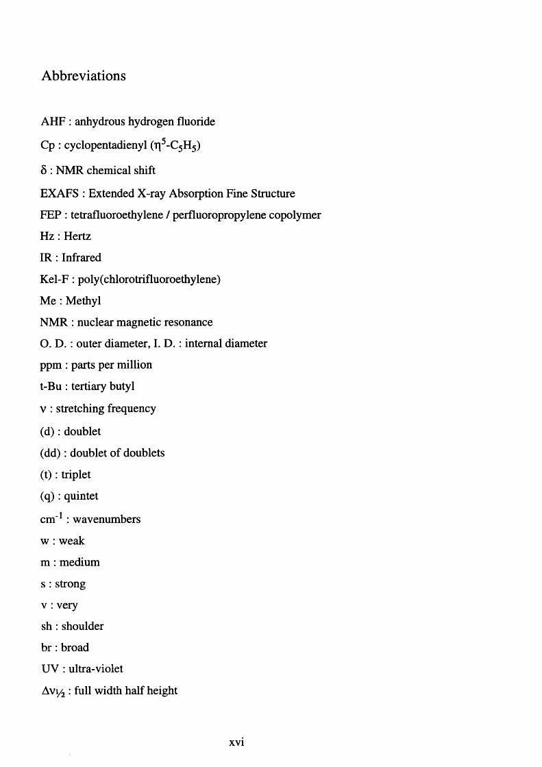
Abbreviations
AHF : anhydrous hydrogen fluoride
Cp : cyclopentadienyl (rj5 -C5 H5)
8 : NMR chemical shift
EXAFS : Extended X-ray Absorption Fine Structure
FEP : tetrafluoroethylene / perfluoropropylene copolymer
Hz : Hertz
I R : Infrared
K e l-F : poly(chlorotrifluoroethylene)
Me : Methyl
NMR : nuclear magnetic resonance
O. D. : outer diameter, I. D . : internal diameter
ppm : parts per million
t-Bu : tertiary butyl
v : stretching frequency
( d ) : doublet
(d d ) : doublet of doublets
( t ) : triplet
( q ) : quintet
cm '1 : wavenumbers
w : weak
m : medium
s : strong
v : very
s h : shoulder
b r : broad
UV : ultra-violet
Avi/ 2 : full width half height
xvi

CHAPTER ONE
Introduction
1.1. General Introduction.
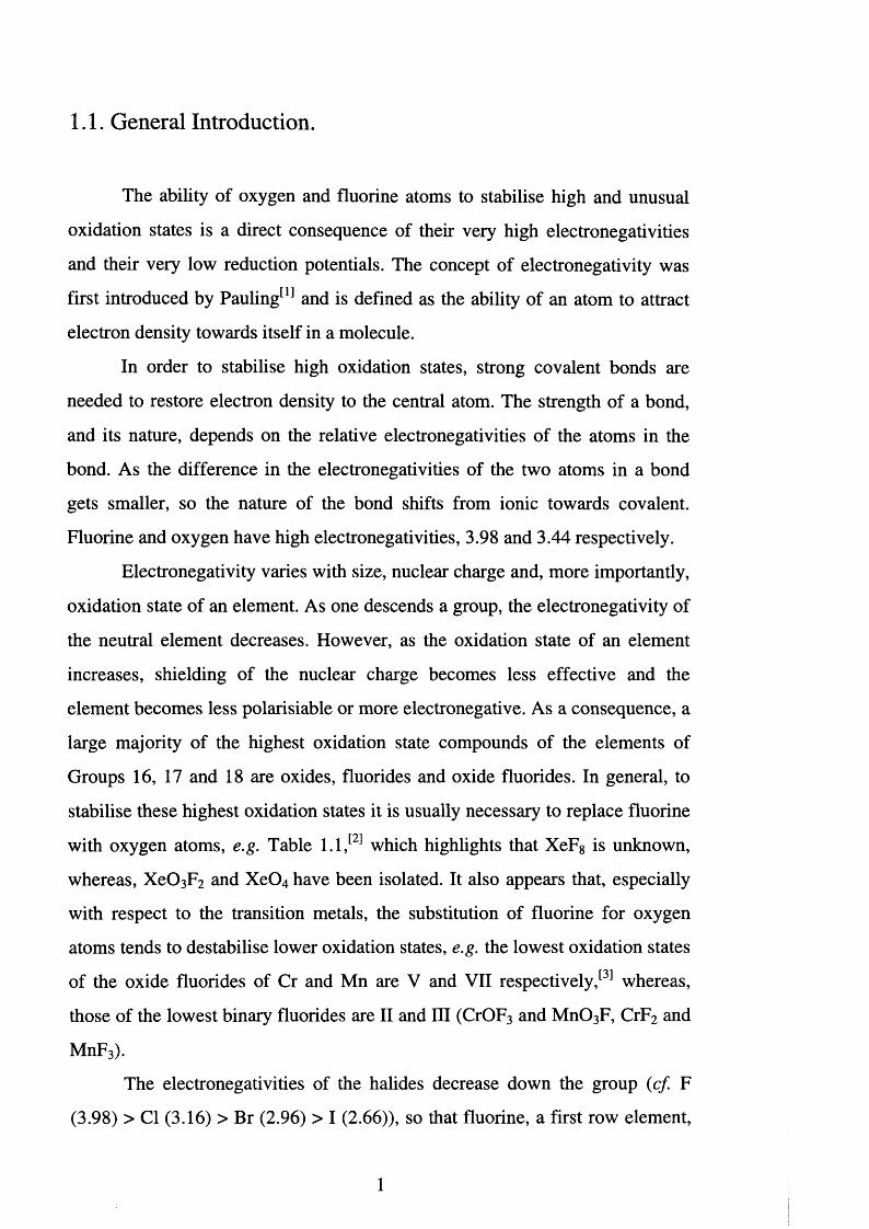
The ability of oxygen and fluorine atoms to stabilise high and unusual
oxidation states is a direct consequence of their very high electronegativities
and their very low reduction potentials. The concept of electronegativity was
first introduced by Pauling[1] and is defined as the ability of an atom to attract
electron density towards itself in a molecule.
In order to stabilise high oxidation states, strong covalent bonds are
needed to restore electron density to the central atom. The strength of a bond,
and its nature, depends on the relative electronegativities of the atoms in the
bond. As the difference in the electronegativities of the two atoms in a bond
gets smaller, so the nature of the bond shifts from ionic towards covalent.
Fluorine and oxygen have high electronegativities, 3.98 and 3.44 respectively.
Electronegativity varies with size, nuclear charge and, more importantly,
oxidation state of an element. As one descends a group, the electronegativity of
the neutral element decreases. However, as the oxidation state of an element
increases, shielding of the nuclear charge becomes less effective and the
element becomes less polarisiable or more electronegative. As a consequence, a
large majority of the highest oxidation state compounds of the elements of
Groups 16, 17 and 18 are oxides, fluorides and oxide fluorides. In general, to
stabilise these highest oxidation states it is usually necessary to replace fluorine
with oxygen atoms, e.g. Table 1.1,[2] which highlights that XeF8 is unknown,
whereas, X e 0 3 F2 and X e0 4 have been isolated. It also appears that, especially
with respect to the transition metals, the substitution of fluorine for oxygen
atoms tends to destabilise lower oxidation states, e.g. the lowest oxidation states
of the oxide fluorides of Cr and Mn are V and VII respectively / 33 whereas,
those of the lowest binary fluorides are II and III (CrOF3 and M n 0 3 F, CrF2 and
MnF3).
The electronegativities of the halides decrease down the group (cf. F
(3.98) > Cl (3.16) > Br (2.96) > I (2.66)), so that fluorine, a first row element,
1
has an electronegativity considerably higher than that of chlorine, bromine or
iodine. These changes in electronegativity are evident in the halide chemistry of
Group 16: SF6, SeF6 and TeF6 are all stable molecular covalent species,1[4]
whereas, the highest oxidation state chlorides are SC12, SeCl4 and TeCl4. This
trend is even more marked for the bromides and iodides, and is a result of the
fact that the heavier halides become progressively more easy to oxidise and are
therefore less able to stabilise high oxidation states.
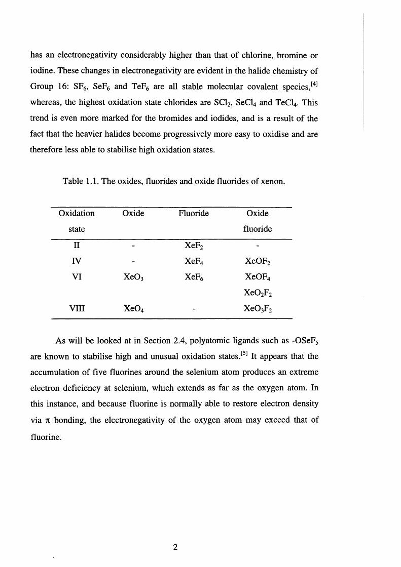
Table 1.1. The oxides, fluorides and oxide fluorides of xenon.
Oxidation
state
Oxide Fluoride Oxide
fluoride
II - XeF2 -
IV - XeF4 XeOF2
VI X e0 3 XeF6 XeOF4
X e0 2 F2
VIII X e0 4 - X e 0 3 F2
As will be looked at in Section 2.4, polyatomic ligands such as -OSeF5
are known to stabilise high and unusual oxidation states.[5] It appears that the
accumulation of five fluorines around the selenium atom produces an extreme
electron deficiency at selenium, which extends as far as the oxygen atom. In
this instance, and because fluorine is normally able to restore electron density
via n bonding, the electronegativity of the oxygen atom may exceed that of
fluorine.
2
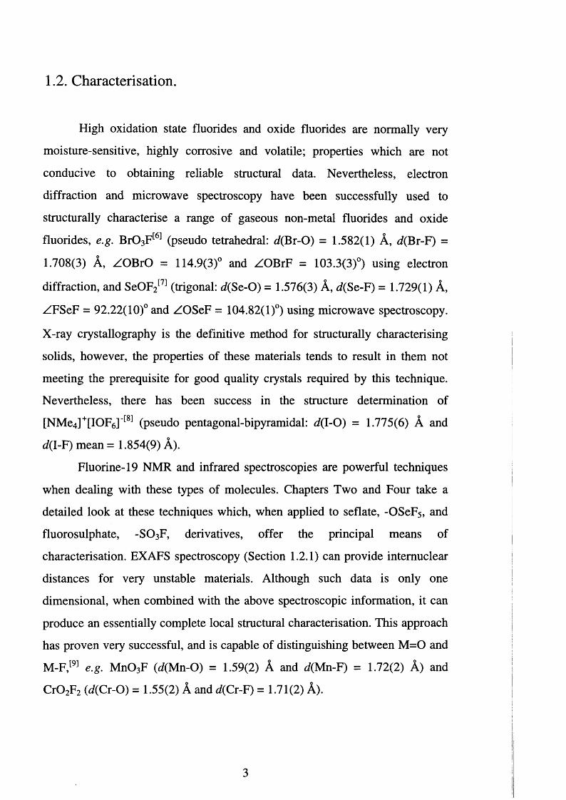
1.2. Characterisation.
High oxidation state fluorides and oxide fluorides are normally very
moisture-sensitive, highly corrosive and volatile; properties which are not
conducive to obtaining reliable structural data. Nevertheless, electron
diffraction and microwave spectroscopy have been successfully used to
structurally characterise a range of gaseous non-metal fluorides and oxide
fluorides, e.g. Br0 3 F[6] (pseudo tetrahedral: d(Br-C>) = 1.582(1) A, d(Br-F) =
1.708(3) A, ZOBrO = 114.9(3)° and ZOBrF = 103.3(3)°) using electron
diffraction, and SeOF2[7] (trigonal: </(Se-0 ) = 1.576(3) A, d(Se-F) = 1.729(1) A, ZFSeF = 92.22(10)° and ZOSeF = 104.82(1)°) using microwave spectroscopy.
X-ray crystallography is the definitive method for structurally characterising
solids, however, the properties of these materials tends to result in them not
meeting the prerequisite for good quality crystals required by this technique.
Nevertheless, there has been success in the structure determination of
[NMe4 ]+[IOF6] '[8] (pseudo pentagonal-bipyramidal: <7(1-0) = 1.775(6) A and
d(I-F) mean = 1.854(9) A).Fluorine-19 NMR and infrared spectroscopies are powerful techniques
when dealing with these types of molecules. Chapters Two and Four take a
detailed look at these techniques which, when applied to seflate, -OSeF5, and
fluorosulphate, -S 0 3 F, derivatives, offer the principal means of
characterisation. EXAFS spectroscopy (Section 1.2.1) can provide intemuclear
distances for very unstable materials. Although such data is only one
dimensional, when combined with the above spectroscopic information, it can
produce an essentially complete local structural characterisation. This approach
has proven very successful, and is capable of distinguishing between M = 0 and
M -F , 191 e.g. Mn0 3F (rf(Mn-O) = 1.59(2) A and d(Mn-F) = 1.72(2) A) and
C r0 2 F 2 W(Cr-O) = 1.55(2) A and </(Cr-F) = 1.71(2) A).
3
1.2.1. EXAFS spectroscopy.
The development of synchrotron radiation sources[10] such as those at the
Daresbury Synchrotron Radiation Laboratory (CCLRC) has provided
experimenters with X-ray sources several orders of magnitude brighter than
those previously obtained from conventional X-ray tubes. The level of
understanding of extended X-ray absorption fine structure (EXAFS)
spectroscopy has advanced such that reliable structural information can be
extracted from X-ray absorption spectra . [ U 1 Additionally, the application of
EXAFS spectroscopy does not require compounds to be crystalline and can
provide structural information on powders, unstable materials, solutions and at
different temperatures.
A typical X-ray absorption spectrum exhibits decreasing absorption as
the photon energy is increased. Superimposed on this smooth background is a
sequence of steeply rising discontinuities in the absorption at energies
characteristic of each element in the sample. These abrupt increases in
absorption occur whenever the incident photon has sufficient energy to promote
a core electron to unoccupied valence levels or to the continuum. The edges are
labelled according to the core electron being promoted, K edge arises from Is
excitation, L edges arise from 2s or 2p excitation and so on. With the discovery
of absorption edges came the observation that the absorption near the edge and
beyond does not vary smoothly, rather, there is a wealth of fine structural
information which is characteristic of the chemical environment of the X-ray
absorbing atom.
A typical absorption edge consists of a series of approximately
Lorentzian lines superimposed on a steeply rising absorption step. Within about
25 eV of the absorption edge most of the structure is due to bound state
transitions. However, additional structural information is observed over several
hundred electron volts past the edge. This long range oscillation, EXAFS, is
considered to result from interference between the atom and the photoelectron
4
wave propagating from the X-ray absorbing atom and the wave backscattered
by neighbouring atoms. The absorption process may be viewed as a one-
electron transition from a highly localised core orbital to a delocalised
continuum state, which is sensitive to the immediate environment of the
absorbing atom. Analysis of the positions and relative intensities of the
absorption edge features can reveal details about the metal site symmetry, its
oxidation state and the nature of the surrounding ligands. More importantly
here, interpretation of the phase, amplitude and frequency of the EXAFS
oscillations can provide information about the type, number and distances of
atoms in the vicinity of the absorber.
In an absorption experiment, ionisation gas detectors are mounted in
front and behind the sample, and the relative absorbance is obtained by taking
the log of the ratio of the currents in each detector. The absorbance of the
particular element of interest is superimposed on both the spectrometer baseline
and the background absorption (due to cell windows, solvent, air and other
elements present in the sample).
The phenomenon known as EXAFS, %, is simply the relative modulation
of the absorption coefficient p, of a particular atom compared with the smooth
background absorption coefficient j l l s, normalised by the absorption coefficient
p 0 that would be observed for the free atom (Eqn. 1.1).
X = (p - Ps)/M« Ecln - L 1-
EXAFS results from interference between the out-going photoelectron
wave from the absorbing atom, and the back scattered waves of the surrounding
atoms. Theoretical determination of EXAFS rests on the ability to calculate the
relative phases and amplitudes of the out-going and the back-scattered
photoelectron waves. In order to interpret an EXAFS spectrum, it is necessary
to subtract the background. This is performed using the program EX,[12]
5
developed at The University of Leicester. The Fourier transform of the EXAFS
from k (k = photoelectron wave vector) space to R (distance) space provides
information about radial distribution. The Fourier transform of a data set from
which the background has not been correctly subtracted usually results in largeo
peaks below 1 A. Curve fitting analysis is carried out to derive a parameterised
function that will model the observed EXAFS, and then iterate the structure
dependent parameters in this theoretical EXAFS spectrum until the fit with the
experimentally observed EXAFS is optimised. This is achieved using the
program EXCURV92.[13] The final values of the optimised EXAFS should
yield structural information about the compound.
A number of variable parameters exist in the program and these include
AFAC, which is the proportion of electrons which perform the EXAFS type
scatter, and VPI, which takes into account inelastic losses and the core hole
lifetime. These values should be comparable for similar types of species.
EXAFS spectroscopy only gives one dimensional information except
when measured for single crystals. However, the sensitivity of the technique is
very high and this characteristic has made it of unique value in the study of
metal-containing biological systems. Overall, EXAFS spectroscopy is an
invaluable technique especially with reference to the work under taken in this
thesis. Although not as accurate as other structural techniques, distances can be
obtained with accuracies of up to ± 0 . 0 1 A, which is excellent considering that,
for the compounds studied in the present work, such information may not be
obtainable by other techniques.
6
1.3. Summary.
The work undertaken in this thesis is concerned with some of the oxide
fluoride chemistry of sulphur, selenium and bromine. The simple oxide
fluorides of sulphur and selenium (SOF2, S 0 2 F2 and SOF4, and SeOF2, S e0 2 F2
and SeOF4) are well known.[3] In addition, there are a whole host of complex
oxide fluorides which, in the case of sulphur, fall into two categories: those
which contain the -S 0 3F group as a structural unit e.g. the series of
polysulphuryl difluorides S2 0 5 F2 - S7 O2 0 F2, and those whose structural group is
-SF5 e.g. SF5 OF, (SF5)20 and (SF5 O) 2. For selenium, a series of complex oxide
fluorides is known e.g. F5 SeOF, (SeF5)20 and (FSeO)2, however, the chemistry
is not as diverse as that observed for sulphur. None of the simple oxide
fluorides of tellurium have been isolated, although, a number of complex oxide
fluorides are known,[3] e.g. (F5Te)20 and (FTeO)2. This chemistry reflects the
increased size of the tellurium atom which leads to an increased coordination
number, hexavalent tellurium usually attaining a coordination number of six.
The work undertaken here was designed to attempt to expand the number of
derivatives and exploit new synthetic pathways to complexes of the S (IV)
(-SO 3 F) and Se (IV) (-OSeF5) fluoroanions. In contrast, the oxide fluoride
chemistry of bromine is not so extensive,[6] and the aim was to attempt to
establish pathways to new bromine oxide fluorides, the properties of which it
was hoped would lead to new areas of coordination and reaction chemistry.
Chapters Two and Four describe the synthesis of novel low-valent metal
derivatives containing the high-valent ligands -SO3 F and -OSeF5. The two
ligands have been described as “pseudo fluorides”, and indeed, the high valent
complexes [Sb(S0 3 F)6]' and [I(OSeF5)5] have few analogues besides their
respective fluoride derivatives, [SbF6]' and IF5. However, as will be shown, in
the area of low valent transition metal derivatives the properties of the -S 0 3F
and -OSeF5 ligands are quite different from that of F', making the term pseudo
fluoride inappropriate. Chapters Two and Four begin with reviews of the areas
7

of interest, and cover the history, synthetic approaches, limitations and a
detailed look at the respective spectroscopic techniques needed to characterise
these type of species.
Chapter Three is directed towards the isolation and characterisation of
the bromine oxide fluorides. These compounds are of fundamental importance
as textbook examples of rare, unusual and discrete molecular geometries. The
introduction consists of a review of halogen oxide fluoride chemistry and
serves to highlight the corresponding dearth of bromine oxide fluorides relative
to the respective chlorine and iodine analogues.
8
References Chapter One
[1] L. Pauling, The Nature o f the Chemical Bond, Ithaca, New York, 3rd
edn., 1960, ch. 3, 64-107.
[2] F. A. Cotton and G. Wilkinson, Advanced Inorganic Chemistry, 5th
edn., 1988, ch. 15.
[3] J. H. Holloway and D. Laycock, Adv. Inorg. Chem. Radiochem., 1983,
27,157 and references cited therein.
[4] N. C. Norman, Periodicity and the p-Block Elements, ed. J. Evans,
Oxford, Oxford, 1st edn., 1994, ch. 5, 57-71.
[5] K. Seppelt, Angew. Chem., Int. Ed. Engl., 1982, 21, 877.
[6 ] R. J. Gillespie and P. H. Spekkens, Isr. J. Chem., 1978,17,11 and
references cited therein.
[7] I. C. Bowater, R. D. Brown and F. R. Burden, J. Mol. Spectrosc., 1968,
28,461.
[8 ] A. Mahjoub and K. Seppelt, J. Chem. Soc., Chem. Commun., 1991, 840.
[9] W. Levason, J. S. Ogden, A. K. Saad, N. A. Young, A. K. Brisdon, P. J.
Holliman, J. H. Holloway and E. G. Hope, J. Fluorine Chem., 1991, 53,
43.
[10] E. A. V. Ebsworth, D. W. H. Rankin and S. Cradock, Structural
Methods in Inorganic Chemistry, Blackwell, Oxford, 2nd edn., 1991,
ch. 1, p. 15.
[11] E. A. V. Ebsworth, D. W. H. Rankin and S. Cradock, Structural
Methods in Inorganic Chemistry, Blackwell, Oxford, 2nd edn., 1991,
ch. 8 , 366-371 and references cited therein.
[12] EX, A. K. Brisdon, University of Leicester, 1992.
[13] EXCURV92, SERC Daresbury Laboratory Program, N. Binstead, J. W.
Campbell and S. J. Gurman, 1992.
9
CHAPTER TWO
Oxidation Reactions using Xenon 5is(seflate)
2.1. Introduction.
The serendipitous discovery of pentafluoroorthoselenic (VI) acid,
HOSeF5, colloquially known as seflic acid, was made by S eppelt^ in 1972.
This followed the similarly unexpected synthesis of pentafluoroorthotelluric
(VI) acid, HOTeF5, (teflic acid) by Engelbrecht^ and Sladky in 1964.
Engelbrecht et al. intended to synthesise T e0 2 F2 by combining Ba[Te04] and
H S 0 3F at 160°C, in a reaction analogous to that used in the preparation of
S e0 2 F2. Tellurium dioxide difluoride, T e0 2 F2, still unknown today, was not
isolated, but instead, HOTeF5 was formed. This was later explained in terms of
the tendency of hexavalent tellurium to achieve a co-ordination number of 6 .
Generally, compounds of the third row of non-metals resemble the second row
of non-metals; whereas an increase in coordination number is observed on
going to the fourth row, e.g. [SO4 ]2', [Se04]2" cf. [H4 T e0 6]2".
Seppelt was attempting to synthesis SeOF4 when he discovered HOSeF5.
The methods he employed were the same as those used to synthesis the
analogous SOF4. The fluorination of SeOF2 using a range of halogen fluorides
or elemental fluorine produced SeF4 and SeF6 respectively. However, the
fluorination of SeOF2 in the presence of HF afforded HOSeF5 (Eqn. 2.1).
Selenium oxide tetrafluoride has since been prepared by the vacuum pyrolysis
of Na[OSeF5 ] J 3 1 It is five coordinate and is the only known example of
hexavalent selenium. As befits this unusual coordination number, it is unstable
above -100°C, forming highly viscous polymeric products.
SeOF2 + F 2 + HF HOSeF5 Eqn. 2.1.
The sulphur analogue of seflate and teflate can be p r e p a r e d , b u t below
-60°C it is kinetically stable to reducing the coordination about the sulphur.
10
Above this temperature it readily releases HF, and consequently has found no
synthetic use to date.
Both HOTeF5 and HOSeF5 are strong Bronsted Lowry acids, and studies
have shown the acid dissociation constant of HOTeF5 to be between that of
concentrated hydrochloric and nitric acids with a pK& = 9 .2 .^ Further work by
Engelbrecht et al. demonstrated that HOTeF5 could be readily converted to
salts , [ 6 , 7 1 opening the door to a whole new area of coordination chemistry; and
teflate derivatives are now known for most elements (Figure 2.1). The ability of
the teflate ligand, [TeF5 0 ] ', to stabilise both high and low oxidation state
compounds is unsurpassed by any other polyatomic ligand, and the extremes of
its covalent and ionic bonding are evident in the compounds Xe(OTeF5 ) 6 and
[Mn(CO)5 (OTeF5)]. The wide variety of teflate chemistry is a consequence of
the high stability of the group and its ease of introduction into a complex.
Several synthetic approaches e x is t^ and include the use of, i) chlorides,
fluorides or methyl compounds, which undergo displacement reactions with
teflic acid to produce the corresponding teflate derivative, and HC1, HF or CH4
respectively ii) boron tris(teflate), B(OTeF5)3, which undergoes metathesis to
generate BF3 iii) xenon bis(teflate), Xe(OTeF5)2, which is an extremely strong
oxidising reagent, and provides a route into teflate derivatives which does not
rely on the replacement of a group as the driving force iv) silver teflate,
[Ag(OTeF5)]2, and mercury bis(teflate), Hg(OTeF5)2, which undergo
displacement reactions with chloride derivatives. (However, these latter
reagents have found only limited use owing to the difficulties involved in their
preparation, and the separation of the products.)
In marked contrast, the high oxidation potential of the Se (VI) centre in
seflic acid has limited its use as a reagent (Tables 2.1 and 2.2); the only
compounds which are compatible with seflic acid being fluorides and oxides.
This can be partially overcome by the use of [Hg(OSeF5)2], itself prepared
from HgF2 and HOSeF5, which reacts gently with chlorides in inert solvents. In
view of the dearth of metal-seflate species and the similarity between the iso-
11
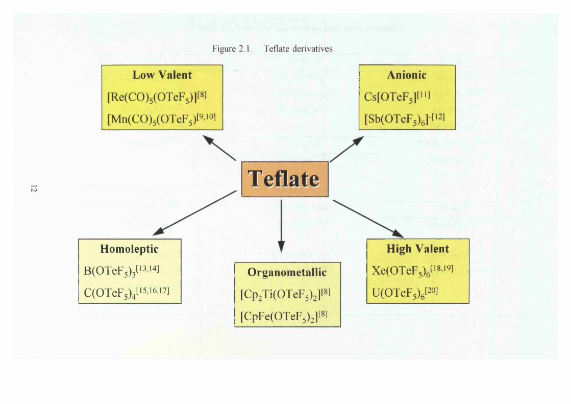
Figure 2.1. Teflate derivatives.
Low Valent Anionic
[Re(CO)5(OTeF5)]t8l Cs[OTeF5][u ]
[Mn(CO)5(OTeF5)[9’10l [Sb(OTeF5)6]‘ti2]
Homoleptic
B(OTeF5)3[13’14]
C(OTeF5)4[15>16>i7]
Teflate
Organometallic
[Cp2Ti(OTeF5)2][8]
[CpFe(OTeF5)2]t8]
High Valent
Xe(OTeFsy i8’19l
U(OTeF5)6t2°l
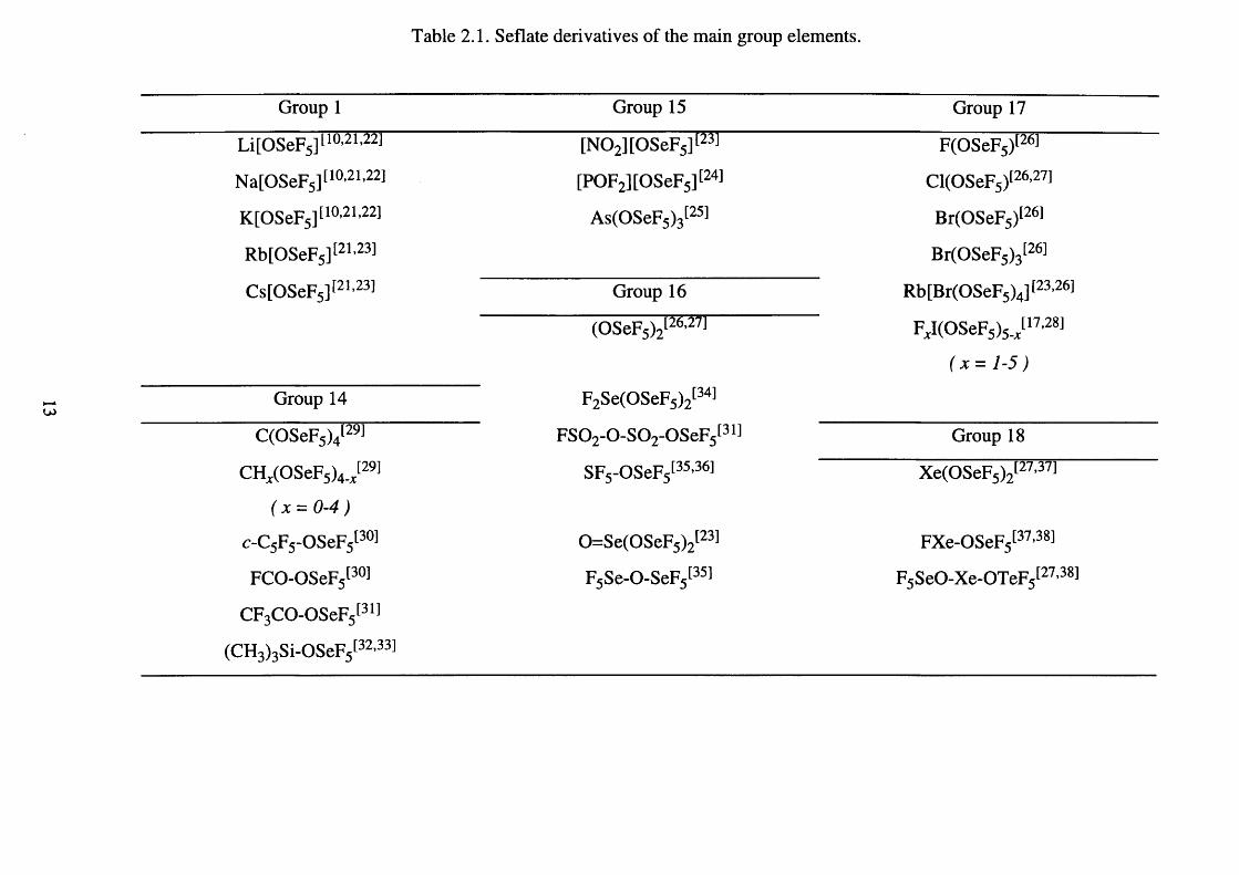
Table 2.1. Seflate derivatives of the main group elements.
Group 1 Group 15 Group 17
Li[OSeF5 ] [ 1 0 >2 1 ’2 2 1 [N 0 2 ][0SeF5] [23) F(OSeF5)[26]
Na[OSeF5] [ia21'22] [POF2 ][OSeF5] [24) Cl(OSeF5 ) [ 2 6 -2 7 1
K[OSeF5 ] [ 1 0 ’2 1 ’2 2 1 As(OSeF5)3[25] Br(OSeF5)[26]
Rb[OSeF5 ] [ 2 1 ' 2 3 1 Br(OSeF5)3[26]
Cs[OSeF5] [21'23] Group 16 Rb[Br(OSeF5 ) 4 ] [ 2 3 -2 6 1
(OSeF5)2[26,27] F,I(OSeF5 )5 J 17'28]
( x = 1-5)
Group 14 F2 Se(OSeF5)2[34l
C(OSeF5)4[29] F S 0 2 -0 -S 0 2 -0SeF5[31] Group 18
CH^(OSeF5)4. ; 29! SF5 -OSeF5[35l36] Xe(OSeF5)2[27,37]
( x = 0 -4 )
o C 5 F5 -OSeF5[30] 0=Se(0SeF 5 ) 2 [ 2 3 1 FXe-OSeF5[37’38]
FCO-OSeF5[30] F5 Se-0-SeF5[35] F5 SeO-Xe-OTeF5I27'38]
CF3 CO-OSeF5[31]
(CH3 )3 Si-OSeF5t32>33]
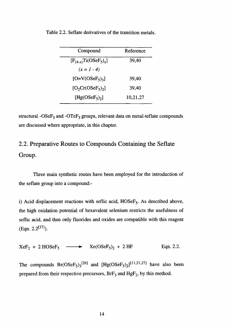
Table 2.2. Seflate derivatives of the transition metals.
Compound Reference
[F(4-i)Ti( ° s eF5) J 39,40
ii i
[0=V (0SeF5)3] 39,40
[0 2 Cr(OSeF5)2] 39,40
[Hg(OSeF5)2] 10,21,27
structural -OSeF5 and -OTeF5 groups, relevant data on metal-teflate compounds
are discussed where appropriate, in this chapter.
2.2. Preparative Routes to Compounds Containing the Seflate
Group.
Three main synthetic routes have been employed for the introduction of
the seflate group into a compound:-
i) Acid displacement reactions with seflic acid, HOSeF5. As described above,
the high oxidation potential of hexavalent selenium restricts the usefulness of
seflic acid, and thus only fluorides and oxides are compatible with this reagent
(Eqn. 2.2[37]).
XeF2 + 2 HOSeF5 --------► Xe(OSeF5 ) 2 + 2 HF Eqn. 2 .2 .
The compounds Br(OSeF<;)^2̂ and [Hg(OSeF5)2]F1,21’27J have also been
prepared from their respective precursors, BrF3 and HgF2, by this method.
14

ii) The difficulty associated with using HOSeF5 can be avoided when using
[Hg(OSeF5)2], this reacts gently with chlorides (Eqn. 2.3).
C H ^C l^ + Vi Hg(OSeF5 ) 2 --------► CHx(OSeF5)4.x + V4HgCl2 Eqn. 2.3.
(x = 0 - 3 )
By this route [CrO2 (OSeF5)2],[39'40] [VO(OSeF5)3],[39'40] C(OSeF5)4[29] and
As(OSeF5)3 2̂9' have been prepared from C r0 2 Cl2, VOCl3, CC14 and AsC13
respectively.
iii) The use of Xe(OSeF5 ) 2 as a clean reagent for the introduction of the seflate
group into molecules has not been exploited at all. The only compounds
produced and studied are thermal and photochemical decomposition
products^35] (Eqn.'s 2.4, 2.5 and 2.6).
U VF 5 SeOXeOSeF5 — — ► 2 OSeF5 -------- ► F5 SeOOSeF5 Eqn. 2.4.
” X G
F5 SeOOSeF5 A » F5 SeOSeF5 + SeF4 + SeF6 + 0 2 Eqn. 2.5.
F,SeOXeOSeF, ---- ► Xe + F5 SeOSeF5 Eqn. 2.6.130 C
Other reagents have found isolated uses in the preparation of seflate
species and these include F2 OPOSeF5 1̂7,28̂ and C10SeF5 2̂8 ̂ (Eqn.’s 2.7 and
2 . 8 respectively).
IF5 + F 2 OPOSeF5 --------► Fxl(OSeF5)5.x + POF3
(x = 0 - 5 )
IC13 + C!OSeF5 ► I(OSeF5 ) 3 + Cl2
Eqn. 2.7.
Eqn. 2.8.
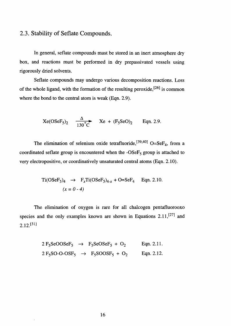
2.3. Stability of Seflate Compounds.
In general, seflate compounds must be stored in an inert atmosphere dry
box, and reactions must be performed in dry prepassivated vessels using
rigorously dried solvents.
Seflate compounds may undergo various decomposition reactions. Loss
of the whole ligand, with the formation of the resulting peroxide,[26] is common
where the bond to the central atom is weak (Eqn. 2.9).
Xe(OSeF5 ) 2 Xe + (F5 SeO ) 2 Eqn. 2.9.
The elimination of selenium oxide tetrafluoridej39,40 ̂ 0=SeF4, from a
coordinated seflate group is encountered when the -OSeF5 group is attached to
very electropositive, or coordinatively unsaturated central atoms (Eqn. 2.10).
Ti(OSeF5 ) 4 -> FJCTi(OSeF5)4_;c + 0=SeF 4 Eqn. 2.10.
(x = 0 - 4 )
The elimination of oxygen is rare for all chalcogen pentafluorooxo
species and the only examples known are shown in Equations 2.11,̂ 27 ̂ and
2 .12. [31]
2 F5 SeOOSeF5 -> F5 SeOSeF5 + 0 2 Eqn. 2.11.
2 F5 S 0 -0 -0 S F 5 -> F5 SOOSF5 + 0 2 Eqn. 2.12.
16
2.4. Electronegativity of the Seflate Anion.
The seflate group resembles fluorine in its ability to stabilise unusual
oxidation states. For example, the compounds I(OSeF5)5, Xe(OSeF5 ) 2 and
Br(OSeF5)3, have few analogues other than their related fluorides. The high
stability of xenon compounds, such as Xe(OTeF5)6, raised the question of the
group's electronegativity. However, electronegativity has no simple definition
and becomes even more ambiguous when applied to a group.
In efforts to determine the group electronegativity of seflate relative to
that of fluorine, a number of investigations have been carried out but with
contrasting results, for example: -
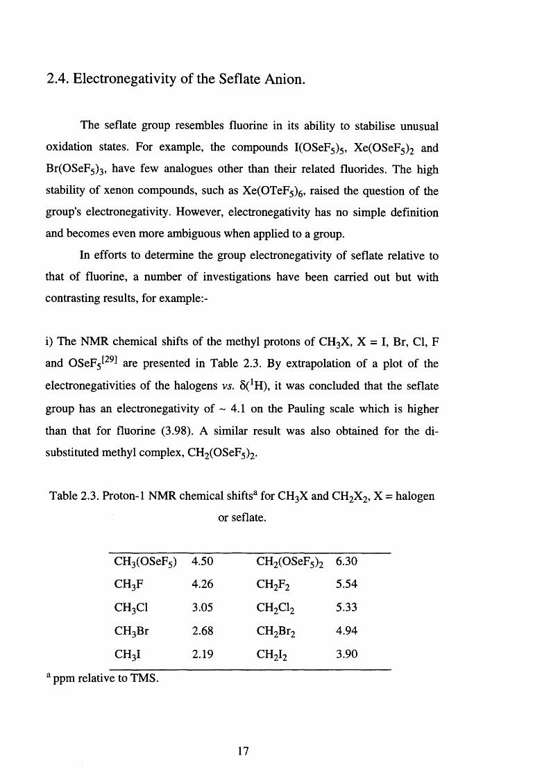
i) The NMR chemical shifts of the methyl protons of CH 3 X, X = I, Br, Cl, F
and OSeF5 2̂9J are presented in Table 2.3. By extrapolation of a plot of the
electronegativities of the halogens vs. 8 ( 1 H), it was concluded that the seflate
group has an electronegativity of ~ 4.1 on the Pauling scale which is higher
than that for fluorine (3.98). A similar result was also obtained for the di
substituted methyl complex, CH2 (OSeF5)2.
Table 2.3. Proton-1 NMR chemical shiftsa for CH3X and CH 2 X2, X = halogen
or seflate.
CH 3 (OSeF5) 4.50 CH2 (OSeF5 ) 2 6.30
c h 3f 4.26 c h 2 f 2 5.54
c h 3c i 3.05 c h 2 c i 2 5.33
CH3Br 2 . 6 8 CH2 Br2 4.94
c h 3i 2.19 c h 2 i 2 3.90
a ppm relative to TMS.
17
ii) The reaction of IF5 with F2 OPOSeF5 leads to substitution of the fluorine
atoms on the iodine by seflate^18,28̂ (Eqn. 2.13).
IF5 + F2 OPOSeF5 -> FxI(OSeF5)5. ̂ + POF3 Eqn. 2.13.
(x = 0 - 5 )
Valence shell electron pair repulsion theory (VSEPR) predicts that in a
square-based pyramid the axial position is always occupied by the least
electronegative ligand. When the above reaction was monitored using 19F NMR
spectroscopy, it was noted that the only reaction when an axial seflate ligand
was observed was when complete substitution occurred, i.e. the formation of
I(OSeF5)5. The behaviour of the seflate ligand cannot be explained kinetically:
longer reaction times and heating do not alter the results. Hence, in accord with
VSEPR theory, the order of the substitution indicates that the seflate group
possesses an electronegativity higher than that of fluorine.
Iodine pentateflate, I(OTeF5)5, cannot be prepared as outlined above, but
may be synthesised via a different route (Eqn.’s 2.14 and 2.15).
IF3 + B(OTeF5 ) 3 -> I(OTeF5 ) 3 + BF3 Eqn. 2.14.
I(OTeF5 ) 3 + Xe(OTeF5 ) 2 -> I(OTeF5 ) 5 + Xe Eqn. 2.15.
iii) The ligand properties of -OSeF5 and -OTeF5 groups in the pseudo-trigonal-
bipyramidal molecules F 2 Se(OSeF5)2, F2 Se(OTeF5 ) 2 and F2 Te(OTeF5 ) 2 have
also been investigated^34 ̂ by 77Se and 125Te NMR spectroscopy. All three
compounds possess axial -OSeF5 or -OTeF5 ligands, with the fluorine ligands
in the equatorial plane. VSEPR theory states that the axial position of a
trigonal-bipyramidal molecule is occupied by the more electronegative ligand;
therefore, this indicates that both seflate and teflate ligands possess a higher
electronegativity than that of fluorine.
18
iv) A correlation of the 31P NMR chemical shifts and P = 0 stretching
frequencies for POF2 -X, X = Cl, F or OSeF5 has indicated[28] that seflate and
fluorine ligands have approximately equal electronegativities.
The evidence presented for seflate complexes closely matches that
obtained for the corresponding teflate systems. However, the teflate anion has
been more extensively studied. Schrobilgen et a l synthesised a series of teflate
compounds of Te, I and Xe and their fluorine analogues, and studied them
using 125Te and 129Xe NMR and 127I and 129Xe Mossbauer spectroscopies J41 ̂
The NMR chemical shifts and Mossbauer quadrupole splittings of the central
Te, I and Xe atoms were used to assess the relative electronegativities of
fluorine and teflate ligands.
In 129Xe and 125Te NMR experiments the chemical shift range is
exceedingly large: ~ 7500 ppm^42 ̂ and 3000 p p m ^ respectively.
Consequently, the chemical shifts are very sensitive to changes in electron
density at the xenon or tellurium nucleus. A comparison of the 129Xe and 125Te
NMR chemical shifts for the above series of compounds, revealed that the
fluoride species were significantly more deshielded than their teflate analogues,
implying that fluoride has a greater electronegativity than that of teflate.
In the Mossbauer spectroscopic studies, isomer-shift differences
between fluorine and teflate containing complexes were investigated. However,
results proved inconclusive as the differences were within experimental error.
The Mossbauer quadrupole splittings recorded for the central xenon, iodine and
tellurium atoms on the other hand, established that fluorine was more
electronegative than the teflate group: the latter being given a value of 3.87
(Pauling’s scale), compared with that of 3.98 for fluorine.
Of the studies carried out, those performed by Schrobilgen appear to be
the most definitive, and indicate that fluorine possesses a greater
19
electronegativity than the teflate group. Although a similar study has not been
carried out on the seflate group, a similar result may be anticipated.
In the case of the trigonal bipyramidal species, the axial and equatorial
regions of space are clearly geometrically different and there appears to be no
exception to the VSEPR rules. In an effort to explain why fluorine occupies the
axial position Schrobilgen su g g e s te d ^ that the fluorine atoms, because of
their high electronegativity, have less electron density close to the central atom
than other ligands. In the case of the seflate ligand, electron density on the
oxygen atom may be significantly diminished by the interaction of the non
bonding electron pairs with the ligand group -SeF5. This pn-dn interaction is
important mainly in systems of very high oxidation states. Hence, although
fluorine is a more electronegative element than oxygen, fluorine needs more
space for its non-bonding pairs of electrons.
The square-based pyramidal geometry of I(OSeF5 ) 5 may be regarded as
a pseudo octahedron. In such a case, the differences between the equatorial and
axial positions become more subtle, making predictions more difficult.
Furthermore, there are a few examples in main group, transition metal and
actinide chemistry were the axial position of a pseudo octahedron is occupied
by the more electronegative ligand. For the iodine dioxide tetrafluoride anion,
[IO2 F4 ]', both cis and trans isomers are known to e x i s t ,^ despite the fact that
oxo ligands normally prefer to adopt a pseudo axial position: doubly bonded
oxygens exhibiting steric characteristics^45 ̂ similar to that of a non-bonded pair
of electrons.
Whilst the precise electronegativity of the seflate group remains
unknown, it is undoubtedly high. This is a consequence of the inductive effect
of the five fluorine atoms bound to selenium, which is augmented by some pn-d
n back bonding between the oxygen and the selenium, the final result being an
electronegativity of a similar magnitude to that of fluorine.
20
2.5. Spectroscopic Characterisation of Seflate Compounds.
Although seflate derivatives are extremely air- and moisture-sensitive,
techniques such as infrared, Raman and multinuclear NMR spectroscopies are
convenient methods for characterisation. Seflate derivatives show characteristic
spectral f in g e rp rin ts ,^ which are sensitive to the type of bonding and
oxidation state of the element to which the seflate is coordinated. The strength
of the selenium-oxygen bond is related to the type of bond which exists
between the oxygen atom and the rest of the molecule. The degree of ionicity of
the seflate ligand can be demonstrated by measuring v(Se-O) in the infrared
spectra and 8 1 9 FAX in the 19F NMR spectra of compounds containing the
ligand. Free [OSeF5] ' would have the strongest interaction between oxygen and
selenium, which would result in a short Se-O bond, a high v(Se-O), and a high
frequency 5 1 9 Fax due to deshielding of the axial fluorine.
2.5.1. Fluorine-19 NMR spectroscopy.
Of the routine analytical techniques 19F NMR spectroscopy is the most
important: the 19F nucleus is a 100% spin Vi with a wide chemical shift range.
The seflate group contains two different fluorine environments, the four
equatorial fluorine atoms Fe and the unique axial fluorine Fa, giving an AX 4
spin s y s t e m A first order AX4 pattern is observed for the majority of ionic
species, invariably the A part of the spectrum being at higher frequency than
the X portion. As the interaction between the seflate and the group to which it
is bound increases, that is to say becomes more covalent, so A and X become
closer, leading to second-order AB4 spectra. This is the case for seflic a c i d ^
where 5Fa 75.9 and 8 Fe 66.1 ppm. For F5 SeO-OSeF5,[27] the A and B4 parts are
nearly coincident, 8 Fa 55.2 and 5Fe 54.4, and the spectrum appears to be a
single resonance. If the covalency increases still further, the A part of the
21
spectrum moves to lower frequency than the B part. This is observed for
CF3 CO-OSeF5 ,̂ 31J 5Fa 61.2 and 5Fe 73.5 ppm.
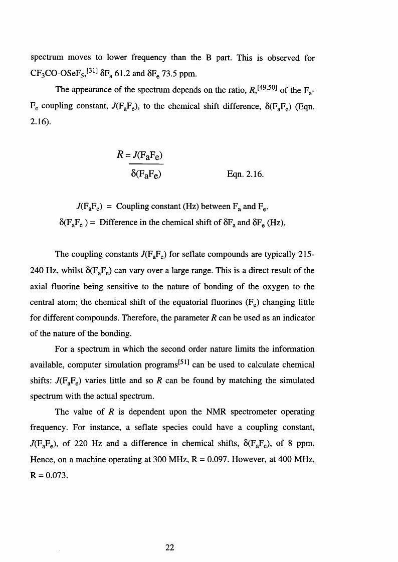
The appearance of the spectrum depends on the ratio, R ,[49,50] Qf the p a.
Fe coupling constant, 7(FaFe), to the chemical shift difference, 5(FaFe) (Eqn.
2.16).
j? = 7(FaFe)
8(FaFe) Eqn. 2.16.
7(FaFe) = Coupling constant (Hz) between Fa and Fe.
5(FaFe ) = Difference in the chemical shift of 5Fa and 5Fe (Hz).
The coupling constants /(F aFe) for seflate compounds are typically 215-
240 Hz, whilst 5(FaFe) can vary over a large range. This is a direct result of the
axial fluorine being sensitive to the nature of bonding of the oxygen to the
central atom; the chemical shift of the equatorial fluorines (Fe) changing little
for different compounds. Therefore, the parameter R can be used as an indicator
of the nature of the bonding.
For a spectrum in which the second order nature limits the information
available, computer simulation programs^5 ̂ can be used to calculate chemical
shifts: /(F aFe) varies little and so R can be found by matching the simulated
spectrum with the actual spectrum.
The value of R is dependent upon the NMR spectrometer operating
frequency. For instance, a seflate species could have a coupling constant,
7(FaFe), of 220 Hz and a difference in chemical shifts, 8 (FaFe), of 8 ppm.
Hence, on a machine operating at 300 MHz, R = 0.097. However, at 400 MHz,
R = 0.073.
22
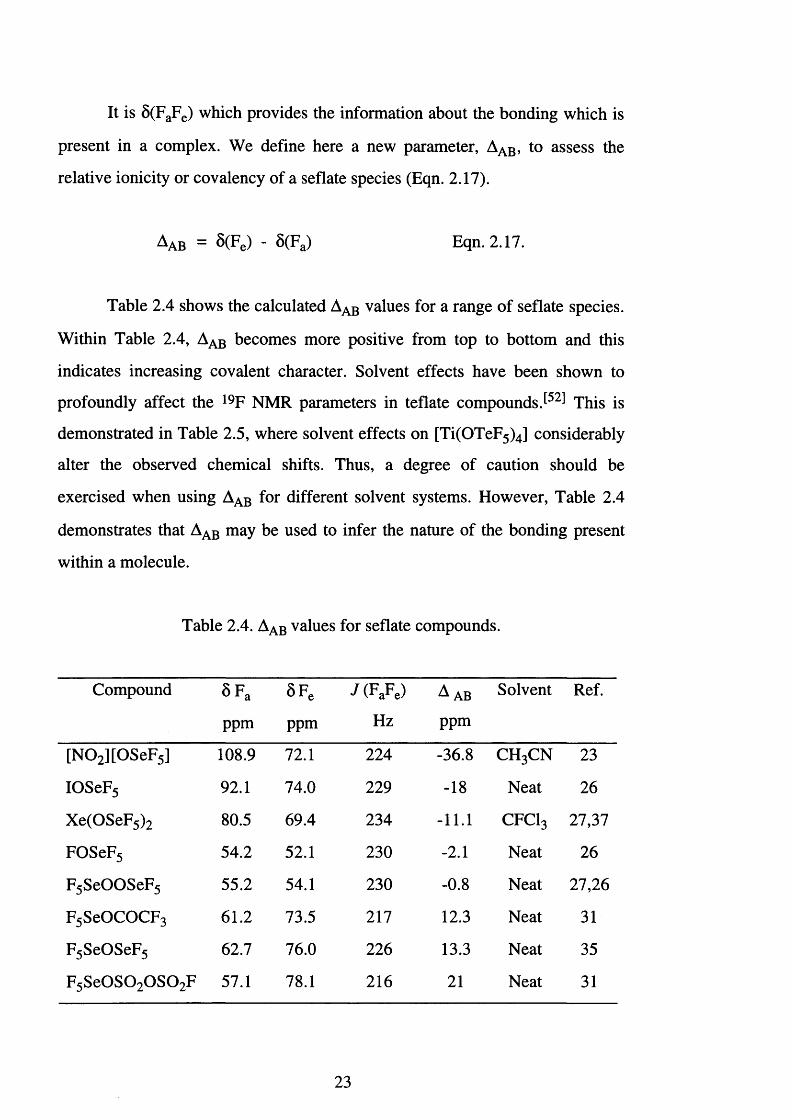
It is 8 (FaFe) which provides the information about the bonding which is
present in a complex. We define here a new parameter, Aa b , to assess the
relative ionicity or covalency of a seflate species (Eqn. 2.17).
Aab = S(Fe) - S(Fa) Eqn. 2.17.
Table 2.4 shows the calculated Aab values for a range of seflate species.
Within Table 2.4, Aab becomes more positive from top to bottom and this
indicates increasing covalent character. Solvent effects have been shown to
profoundly affect the 19F NMR parameters in teflate compounds This is
demonstrated in Table 2.5, where solvent effects on [Ti(OTeF5)4] considerably
alter the observed chemical shifts. Thus, a degree of caution should be
exercised when using Aab for different solvent systems. However, Table 2.4
demonstrates that Aab may be used to infer the nature of the bonding present
within a molecule.
Table 2.4. Aab values for seflate compounds.
Compound SFa 5 F e J ( FaFe) A ab Solvent Ref.
ppm ppm Hz ppm
[N 0 2 ][OSeF5] 108.9 72.1 224 -36.8 c h 3c n 23
IOSeF5 92.1 74.0 229 -18 Neat 26
Xe(OSeF5 ) 2 80.5 69.4 234 - 1 1 . 1 c f c i 3 27,37
FOSeF5 54.2 52.1 230 -2 . 1 Neat 26
F5 SeOOSeF5 55.2 54.1 230 -0 . 8 Neat 27,26
F5 SeOCOCF3 61.2 73.5 211 12.3 Neat 31
F 5 SeOSeF5 62.7 76.0 226 13.3 Neat 35
F 5 S e 0 S 0 2 0 S 0 2F 57.1 78.1 216 2 1 Neat 31
23
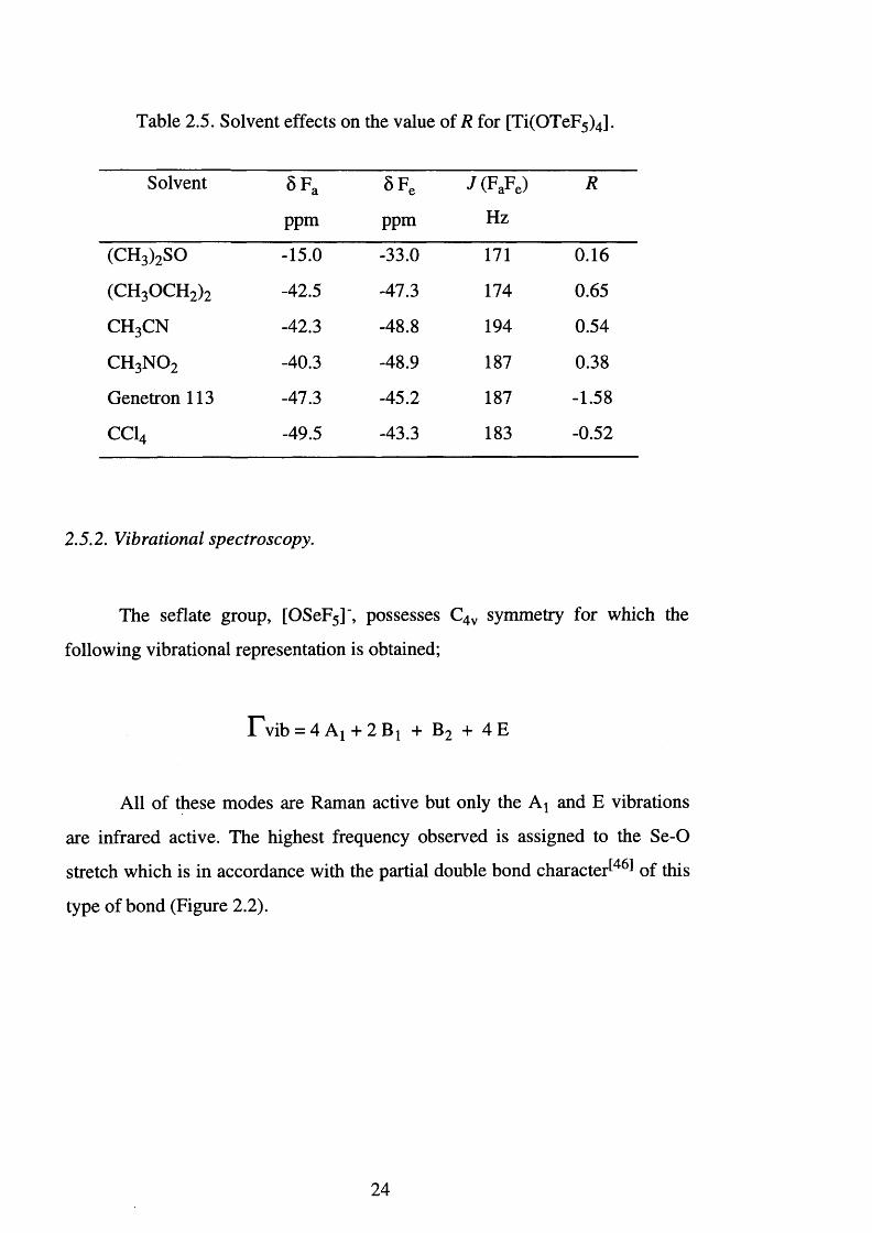
Table 2.5. Solvent effects on the value of R for [Ti(OTeF5)4] .
Solvent §Fa SFe J (FaFe) R
ppm ppm Hz
(CH3)2SO -15.0 -33.0 171 0.16
(CH 3 OCH 2 ) 2 -42.5 -47.3 174 0.65
c h 3c n -42.3 -48.8 194 0.54
c h 3 n o 2 -40.3 -48.9 187 0.38
Genetron 113 -47.3 -45.2 187 -1.58
CC14 -49.5 -43.3 183 -0.52
2.5.2. Vibrational spectroscopy.
The seflate group, [OSeF5]", possesses C4v symmetry for which the
following vibrational representation is obtained;
rV ib = 4 A | + 2 Bj + B 2 + 4 E
All of these modes are Raman active but only the Ay and E vibrations
are infrared active. The highest frequency observed is assigned to the Se-O
stretch which is in accordance with the partial double bond character^46 ̂ of this
type of bond (Figure 2.2).
24
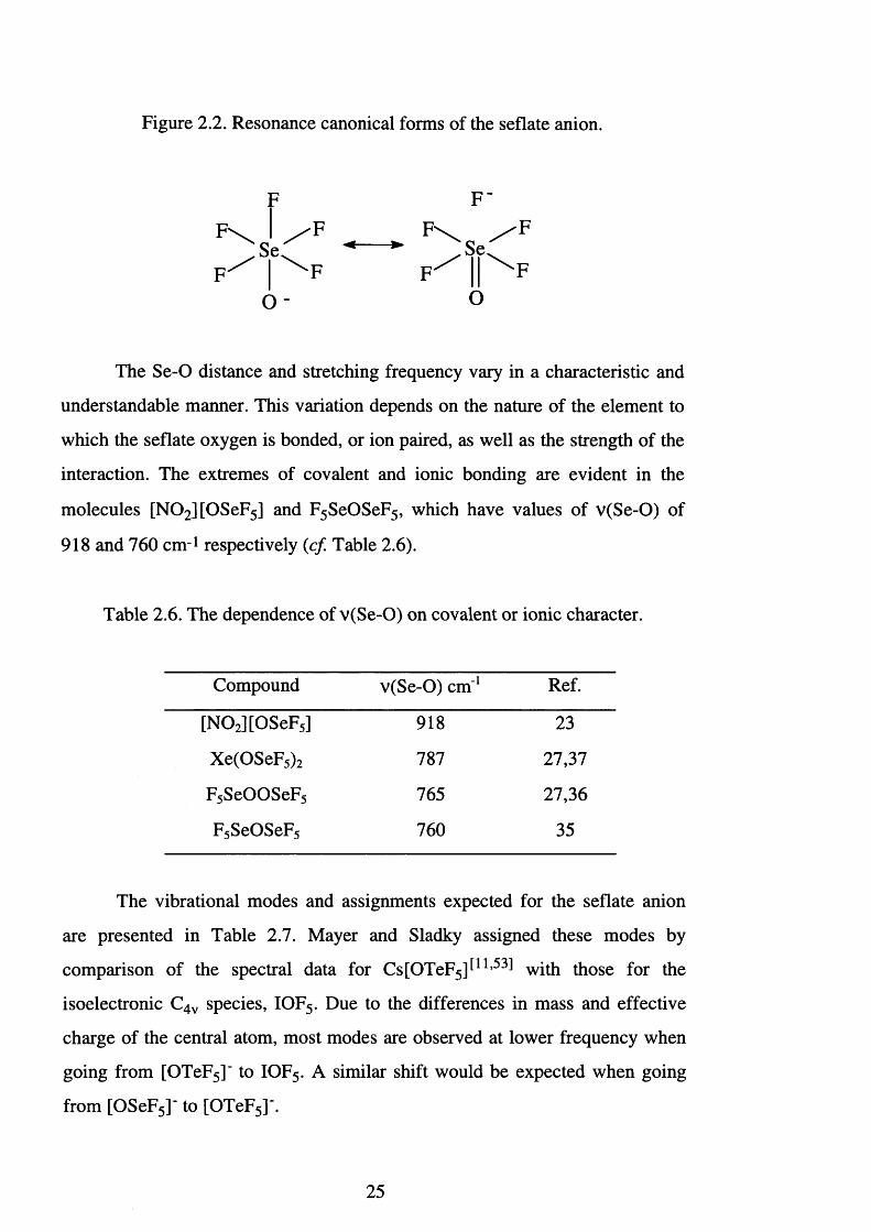
Figure 2.2. Resonance canonical forms of the seflate anion.
Se,
o -
F \ / F .S e ,
O
The Se-O distance and stretching frequency vary in a characteristic and
understandable manner. This variation depends on the nature of the element to
which the seflate oxygen is bonded, or ion paired, as well as the strength of the
interaction. The extremes of covalent and ionic bonding are evident in the
molecules [N 0 2 ][0SeF5] and F5 SeOSeF5, which have values of v(Se-O) of
918 and 760 cm - 1 respectively (c f Table 2.6).
Table 2.6. The dependence of v(Se-O) on covalent or ionic character.
Compound v(Se-O) cm ' 1 Ref.
[N 0 2 ][0SeF5] 918 23~~
Xe(OSeF5 ) 2 787 27,37
F5 SeOOSeF5 765 27,36
F5 SeOSeF5 760 35
The vibrational modes and assignments expected for the seflate anion
are presented in Table 2.7. Mayer and Sladky assigned these modes by
comparison of the spectral data for Cs[OTeF5]^11,53̂ with those for the
isoelectronic C4v species, IOF5. Due to the differences in mass and effective
charge of the central atom, most modes are observed at lower frequency when
going from [OTeF5]' to IOF5. A similar shift would be expected when going
from [OSeF5]‘ to [OTeF5]'.
25
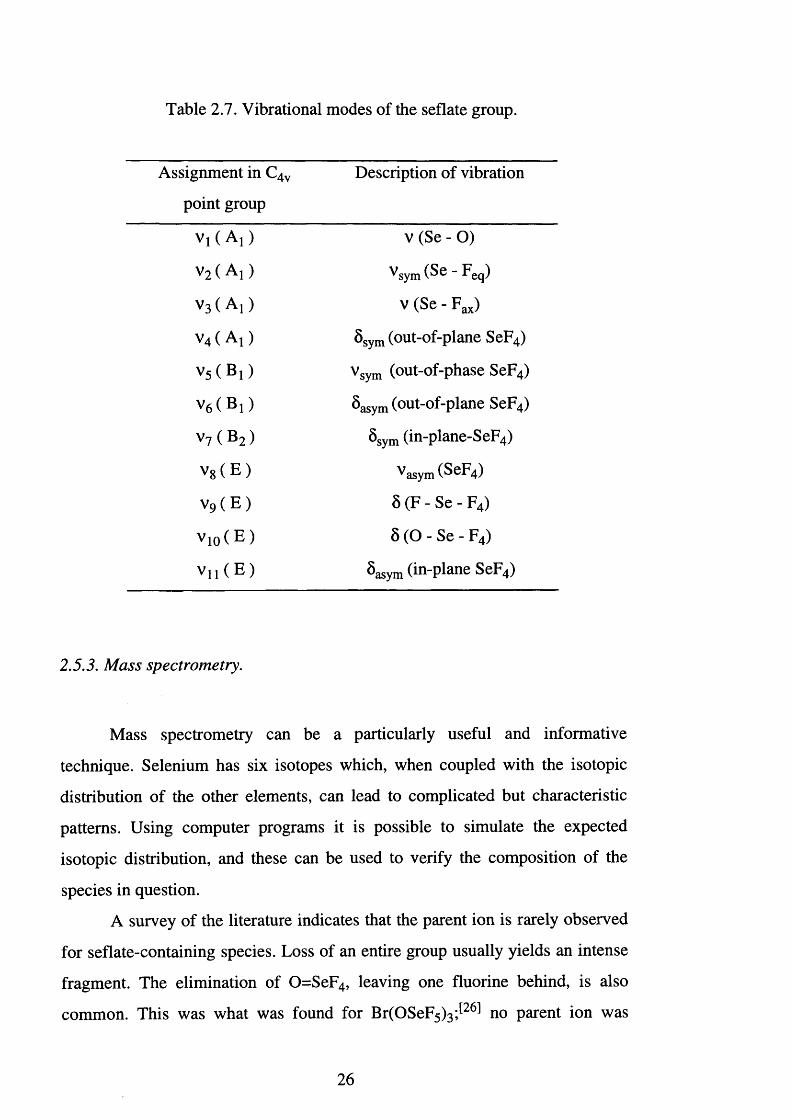
Table 2.7. Vibrational modes of the seflate group.
Assignment in C4v
point group
Description of vibration
V i( A j) v (Se - 0 )
v 2 ( A i ) ^ sy m ( ^ 6 - Feq)
v 3 ( A i ) v (Se - Fax)
v4 ( A j) 8 sym (out-of-plane SeF4)
v 5 ( B ! ) vsym (out-of-phase SeF4)
V6 ( B ! ) 8a sy m (out-of-plane SeF4)
v 7 ( B 2 ) 8 sym (in-plane-SeF4)
v 8 ( E ) ^ a sy m (ScF4)
v 9 ( E ) 8 (F - Se - F4)
v i o ( E ) 8 (O - Se - F4)
V n ( E ) S asym (in-plane SeF4)
2.5.3. Mass spectrometry.
Mass spectrometry can be a particularly useful and informative
technique. Selenium has six isotopes which, when coupled with the isotopic
distribution of the other elements, can lead to complicated but characteristic
patterns. Using computer programs it is possible to simulate the expected
isotopic distribution, and these can be used to verify the composition of the
species in question.
A survey of the literature indicates that the parent ion is rarely observed
for seflate-containing species. Loss of an entire group usually yields an intense
fragment. The elimination of 0=SeF4, leaving one fluorine behind, is also
common. This was what was found for Br(OSeF5 ) 3 ; [ 2 6 1 no parent ion was
26
observed, but the loss of a seflate group produced [Br(OSeF5)2]+, m/z 461
(6 %), and the subsequent loss of 0=SeF 4 produced [FBr(OSeF5)]+, m/z 289
(8%).
Of the ionisation techniques available, electron impact has been the most
useful to date. This technique requires the sample to be slightly volatile. It is
then ionised by an interaction with a beam of electrons to produce a radical
cation, [M']+. The drawbacks are that thermal decomposition may occur during
the vaporisation of the sample and only a limited mass range is accessible,
(<103 AMU).
Other techniques such as electrospray and fast atom bombardment
(FAB), possess an upper mass limit of 9000 AMU and do not require the
samples to be volatile. However, these techniques offer no advantages for the
characterisation of moisture-sensitive seflate-containing compounds as they
require the sample to be solvated in either methanol-water, glycerol or
nitrobenzyl alcohol.
2.5.4. X-ray crystallography and EXAFS spectroscopy.
While single crystal X-ray crystallography offers the ideal method with
which to determine molecular structures, the only successful crystal structure
determination of a seflate containing compound to date is that of xenon
bis(seflate)J2°l
Isolating suitable single crystals is the problem. Single crystals of seflate
derivatives ought to be best prepared by vacuum sublimation. However, the
technique is notorious for the disorder it produces and the problem is enhanced
by the spherical shape of the seflate ligands. Even in the absence of systematic
disorder, the peripheral fluorine atoms appear with very large vibrational
parameters, caused by a combination of molecular vibrations and disorder. This
problem can be reduced by performing the experiments at low temperature, but
27
varying the temperature may result in a phase transition or powdering of the
crystal.
It seemed likely, therefore, that EXAFS spectroscopy might be the ideal
technique for the determination of element-element distances as explained in
Chapter One.
2.6. Covalent Bonding.
An atom in a high oxidation state requires strong covalent bonds to
stabilise it. However, the ligands which can do this must possess a high
electronegativity, otherwise, a redox reaction will take place. The seflate ligand
is able to stabilise high oxidation states and compounds such as I(OSeF5 ) 5 and
Xe(OSeF5 ) 2 have few analogues outside of fluorine chemistry.
Using electron diffraction a structural investigation was carried out on
bis(pentafluoroselenium) oxide, F5 SeOSeF5 J35,36 ̂ The structure consists of
octahedra linked via an oxide bridge (Figure 2.3).
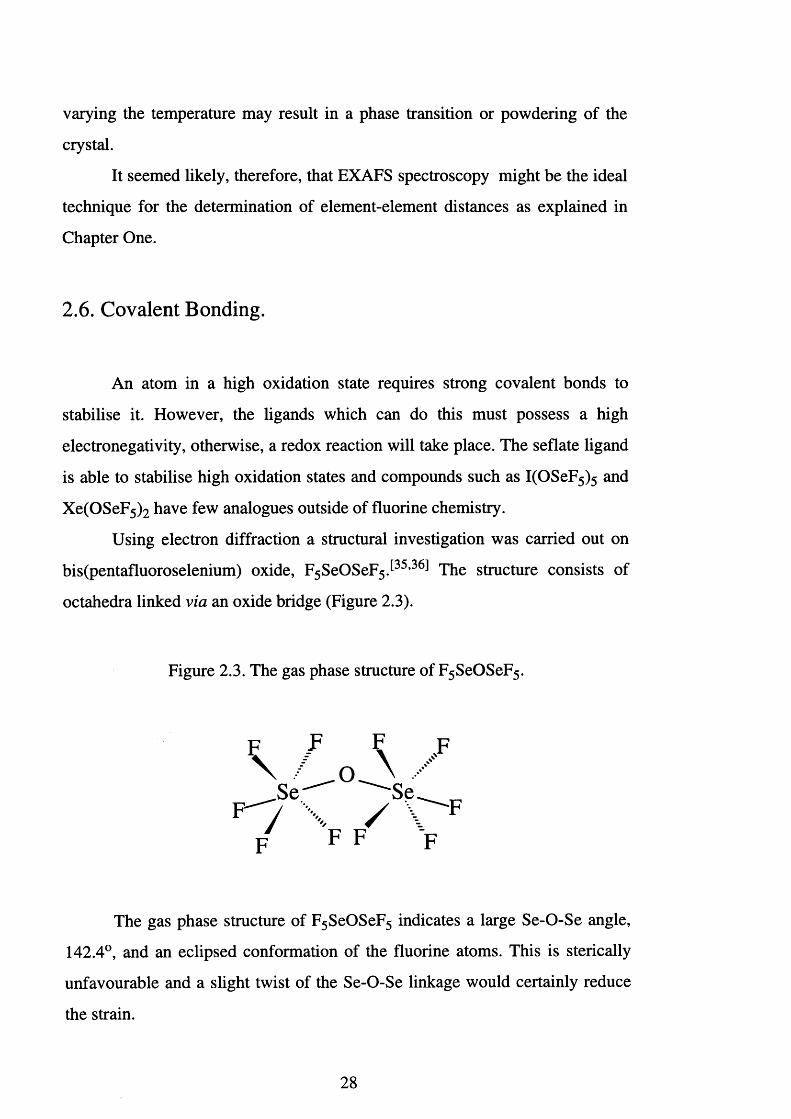
The gas phase structure of F5 SeOSeF5 indicates a large Se-O-Se angle,
142.4°, and an eclipsed conformation of the fluorine atoms. This is sterically
unfavourable and a slight twist of the Se-O-Se linkage would certainly reduce
the strain.
Figure 2.3. The gas phase structure of F5 SeOSeF5.
28
The bridge angle is large and constant (about 143°) for the three
chalcogen species F5 SOSF5, F5 SeOSeF5 and F5 TeOTeF5. This is at variance
with the fact that steric interactions between the equatorial fluorines diminishes
considerably in the sequence F5 SOSF5 > F5 SeOSeF5 > F 5 TeOTeF5.
Characterisation of F5 SOSF5 3̂5,36 ̂ shows the equatorial fluorines are bent 2.1°
away from the octahedral orientation, but this effect diminishes in F 5 SeOSeF5
(1.1°) and disappears for F5 TeOTeF5. Steric interactions would be expected to
cause a lengthening of the O-X bond together with an increase in the bond
angle. Therefore, delocalisation of the oxygen lone pairs is resulting in a pn-dn
contribution to the O-X bond. This is evidenced by a shortening of the O-X
distance.
The Se-O bond distance of 1.697(13) A for F5 SeOSeF5, is between that
of a double and a single bond value (Se0 2 (Se=0 ) = 1.61(1) A and ethylene
selenite, (Se-O) = 1.80(2) A)J35,361 Therefore, on the basis of the short bonds,
large E-O-E angle, as well as the sterically unfavourable eclipsed manner of the
equatorial fluorines, one can assume a considerable amount of double bond
character for the E-O bond in 0(E F5)2, (E = chalcogen).
The shortening of the Se-O bond may also be explained in terms of
hyperconjugation. These resonance modes (Figure 2.2) would give rise to a
shortening of the oxygen bond, and a corresponding lengthening of the fluorine
bonds, especially the axial bond. However, no lengthening of the fluorine bonds
is observed. Thus, pn-dn bonding is favoured as an explanation for the
structural character of F 5 SeOSeF5, F5 SOSF5 and F5 TeOTeF5.
2.7. Ionic Bonding.
Attempts have been made to isolate alkali group metal teflate salts in
order to determine the electronic and molecular properties of the uncoordinated
teflate anionJ5 4 1 Salts such as Cs[OTeF5][11] and [NBun4 ][OTeF5] [55] were
29
initially put forward as models for the free teflate anion. These exhibit the
highest tellurium-oxygen stretching frequencies known, 873 and 867 cm - 1
respectively. However, structural analysis is difficult due to similarities in the
covalent and van der Waals' radii of oxygen and fluorine and fluorine-oxygen
site disorder.
The compound [(PS)H]+[OTeF5]" [(PS)H+ = protonated 1,8-
bis(dimethylamino)naphthalene] J 55,56 ̂was examined by X-ray crystallography.
Unlike the other salts of the OTeF5' anion, it does not exhibit any oxygen-
fluorine disorder. The spectroscopic data, v(Te-O) = 865 cm ' 1 and r(Te-O) =
1.803(3) A, closely match that for [NBun4 ][OTeF5], and it was concluded that
this structure contains the best approximation to that of the free OTeF5' anion.
This work confirmed that, as the negative charge of the teflate is localised on
the oxygen, the tellurium-oxygen bond shortens, the corresponding stretching
frequency increases and the 19F NMR chemical shift of the fluorine trans to the
oxygen, shifts to higher frequency.
In 1984, Strauss et a l successfully made the first low valent transition
metal teflate complex [Mn(CO)5 (OTeF5)], by the reaction of [Mn(CO)5 (CH3)]
and HOTeF5 J 9 , 1 0 , 5 7 1 Fluorine-19 NMR and infrared spectral data were
consistent with the compound having a considerable degree of ionic character.
Single crystal X-ray analysis showed a short Te - 0 distance of 1.751(11) A, which is indicative of Te-O n bonding and reflects the highly ionic character of
this species. The staggered confirmation of the OTeF5 group with respect to the
Mn(CO ) 5 moiety precludes O-Mn n bonding.
Seflate compounds, in accordance with their scarcity, have been less
well studied. The closest model to uncoordinated seflate is [N 0 2 ][0SeF 5 ] , t 2 3 1
for which v(Se-O) = 918 cm - 1 (this compares with v(Te-O) = 848 cm " 1 in
[Mn(CO)5 (OTeF5)]) and its 19F NMR spectrum showed 8Fa108.9, 8 Fe 72.1
ppm and Aab -36.8. Some indication of the ionic nature of the bonding present
within a seflate derivative can be derived by comparison with this data.
30
2.8. Xenon Bis(seflate).
Xenon difluoride in organic solvents has been successfully used to
oxidise low-valent transition metal compounds to produce the corresponding
metal fluorides. Recent work at Leicester showed that Xe(OTeF5 ) 2 can be used
in a similar fashion to generate low-valent transition metal teflate complexes.
By direct analogy with these reactions, we have attempted to use xenon
bis(seflate), Xe(OSeF5)2, as a reagent for the introduction of the seriate group
into a metal co-ordination sphere.
Xenon bis(seflate), Xe(OSeF5)2, was originally prepared according to
the following metathetical reaction^37] (Eqn. 2.18).
XeF2 + 2H O SeF 5 -» Xe(OSeF5 ) 2 + 2H F Eqn. 2.18.
This involves the use of seflic acid, HOSeF5 which is both difficult to
prepare and handle. The synthesis of seflic acid^1,27,48̂ is based upon the
equilibrium reaction shown in Equation 2.19. In accordance with Le Chatelier’s
principle the reaction is shifted to the right by removal of the volatile
components, HF, S e0 2 F 2 and HOSeF5 from the involatile H2 S e04.
3 S e0 2 F2 + 4 HF H2 Se0 4 + 2 HOSeF5 Eqn. 2.19.
The seflic acid product is difficult to isolate as a crystalline solid at room
temperature, due to HF impurities which are extremely hard to remove. Yields
are variable but generally in the region 19 to 6 8 %.
A more convenient and cleaner route to xenon bis(seflate) is the
oxidation of selenium oxide difluoride, SeOF2, by xenon difluoride[58] (Eqn.
2.20).
31
2 SeOF2 + 3 XeF2 Xe(OSeF5)2 + 2 Xe Eqn. 2.20.
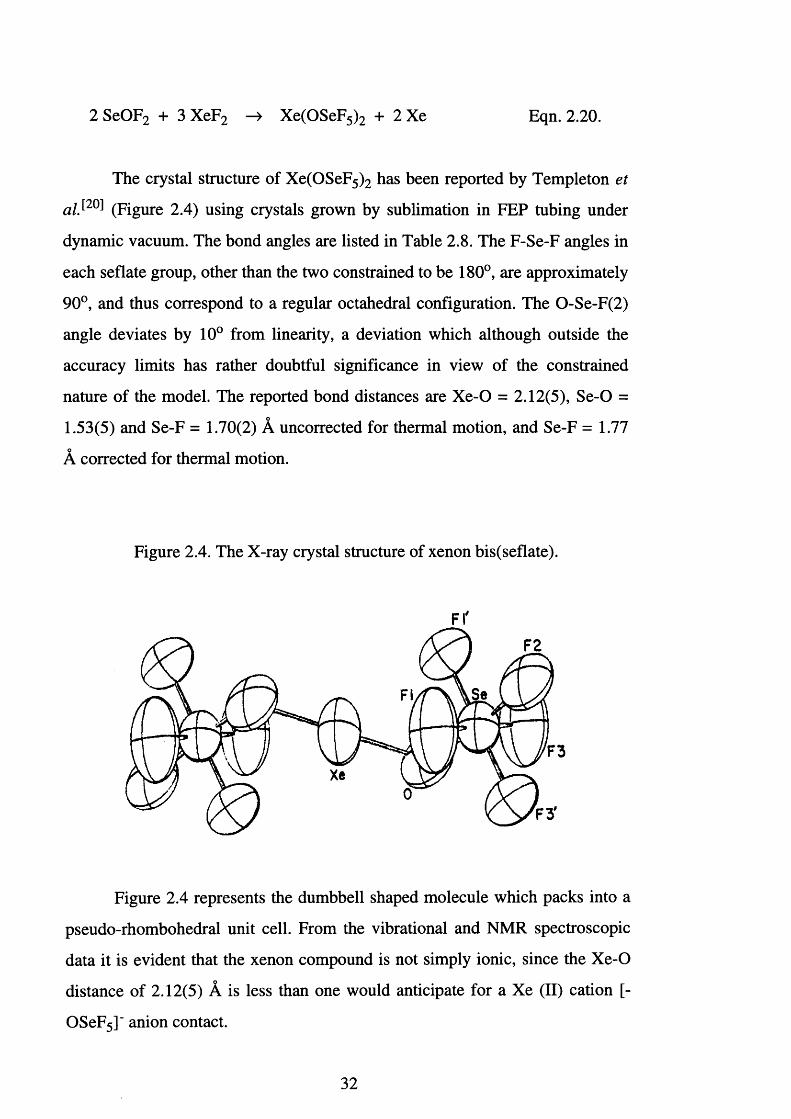
The crystal structure of Xe(OSeF5 ) 2 has been reported by Templeton et
alS20] (Figure 2.4) using crystals grown by sublimation in FEP tubing under
dynamic vacuum. The bond angles are listed in Table 2.8. The F-Se-F angles in
each seflate group, other than the two constrained to be 180°, are approximately
90°, and thus correspond to a regular octahedral configuration. The 0-Se-F(2)
angle deviates by 1 0 ° from linearity, a deviation which although outside the
accuracy limits has rather doubtful significance in view of the constrained
nature of the model. The reported bond distances are Xe-O = 2.12(5), Se-O =
1.53(5) and Se-F = 1.70(2) A uncorrected for thermal motion, and Se-F = 1.77
A corrected for thermal motion.
Figure 2.4. The X-ray crystal structure of xenon bis(seflate).
FI'
3
Figure 2.4 represents the dumbbell shaped molecule which packs into a
pseudo-rhombohedral unit cell. From the vibrational and NMR spectroscopic
data it is evident that the xenon compound is not simply ionic, since the Xe-O
distance of 2.12(5) A is less than one would anticipate for a Xe (II) cation [-
OSeF5]" anion contact.
32
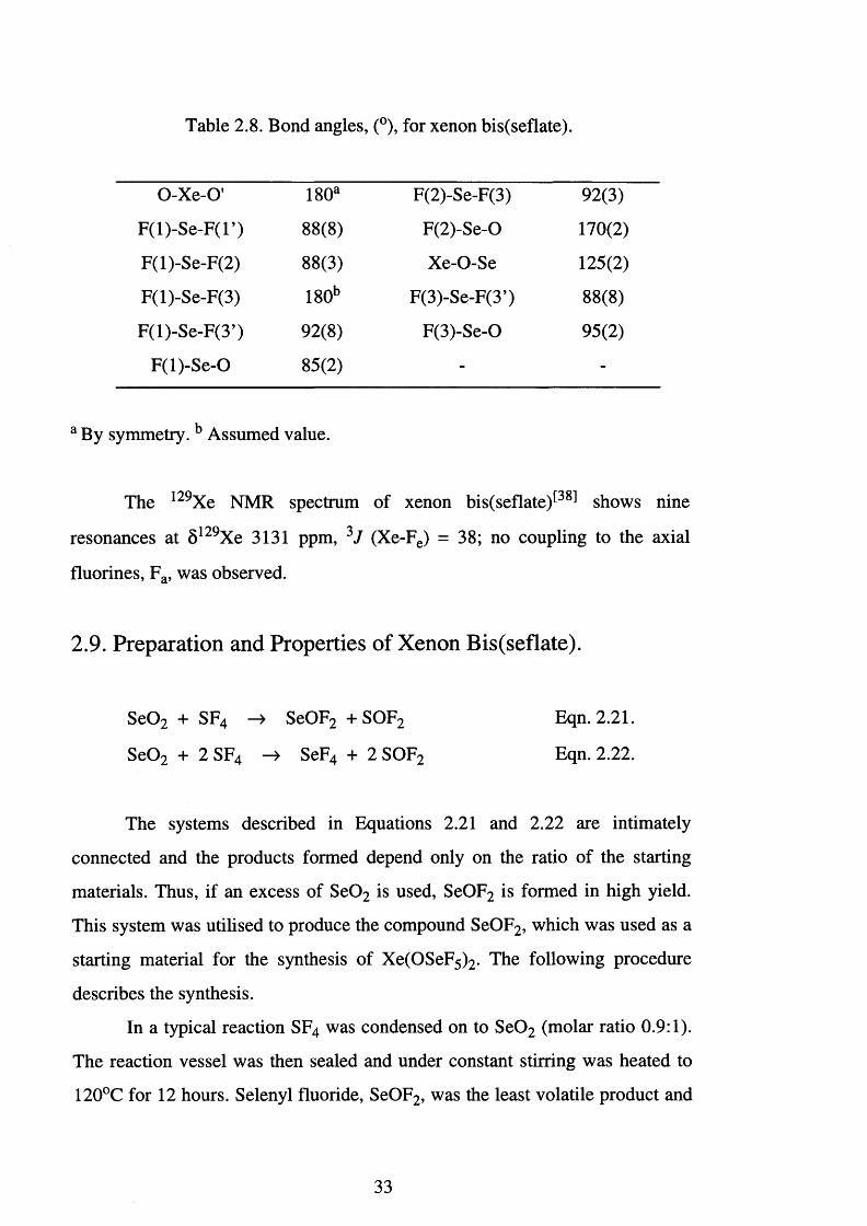
Table 2.8. Bond angles, (°), for xenon bis(seflate).
O-Xe-O’ 180a F(2)-Se-F(3) 92(3)
F (l)-S e-F (l’) 8 8 (8 ) F(2)-Se-0 170(2)
F(l)-Se-F(2) 88(3) Xe-O-Se 125(2)
F(l)-Se-F(3)
X)0
00
r—H F(3)-Se-F(3’) 8 8 (8 )
F(l)-Se-F(3’) 92(8) F(3)-Se-0 95(2)
F(l)-S e-0 85(2) - -
a By symmetry. b Assumed value.
The 129Xe NMR spectrum of xenon bis(seflate)[38] shows nine
resonances at 5129Xe 3131 ppm, 3J (Xe-Fe) = 38; no coupling to the axial
fluorines, Fa, was observed.
2.9. Preparation and Properties of Xenon Bis(seflate).
S e0 2 + SF4 —> SeOF2 + SOF2 Eqn. 2.21.
S e0 2 + 2 SF4 —) SeF4 + 2 SOF2 Eqn. 2.22.
The systems described in Equations 2.21 and 2.22 are intimately
connected and the products formed depend only on the ratio of the starting
materials. Thus, if an excess of S e0 2 is used, SeOF2 is formed in high yield.
This system was utilised to produce the compound SeOF2, which was used as a
starting material for the synthesis of Xe(OSeF5)2. The following procedure
describes the synthesis.
In a typical reaction SF4 was condensed on to S e0 2 (molar ratio 0.9:1).
The reaction vessel was then sealed and under constant stirring was heated to
120°C for 12 hours. Selenyl fluoride, SeOF2, was the least volatile product and
33
was collected by pumping under dynamic vacuum into a trap cooled to -78°C.
Xenon difluoride was loaded into a prepassivated FEP trap and attached to the
Monel line. The SeOF2 was then condensed on to the XeF2 and, upon warming
to room temperature, a steady reaction occurred (Eqn. 2.20) xenon being
evolved for around two hours. The mixture was allowed to equilibrate by
stirring overnight. The volatile materials were removed at room temperature by
pumping under dynamic vacuum for three hours, after which time crystals of
Xe(OSeF5 ) 2 were obtained.
Xenon bis(seflate ) [ 2 7 , 3 7 1 is a colourless solid at room temperature. It is
extremely moisture sensitive, hence, reactions and storage must be carried out
in prepassivated FEP, Kel-F or other fluoroplastic apparatus. Scorching may
occur on contact with susceptible materials, and explosive reactions may occur
with unsaturated organic solvents.
Melting point 69°C
Boiling point
Thermal stability < 130°C
Molecular weight 511
Vapour pressure 0.05 torr @ 0°C
0.35 torr @ 25°C
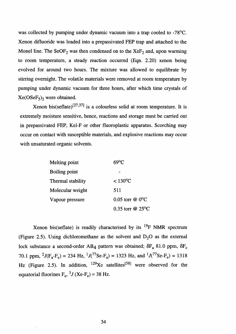
Xenon bis(seflate) is readily characterised by its 19F NMR spectrum
(Figure 2.5). Using dichloromethane as the solvent and D20 as the external
lock substance a second-order AB4 pattern was obtained; 5Fa 81.0 ppm, 8 Fe
70.1 ppm, 2 /(F a-Fe) = 234 Hz, V(7 7 Se-Fa) = 1323 Hz, and V ^ S e-F e) = 1318
Hz (Figure 2.5). In addition, 129Xe satellites^5 8 1 were observed for the
equatorial fluorines Fe, 3J (Xe-Fe) = 38 Hz.
34
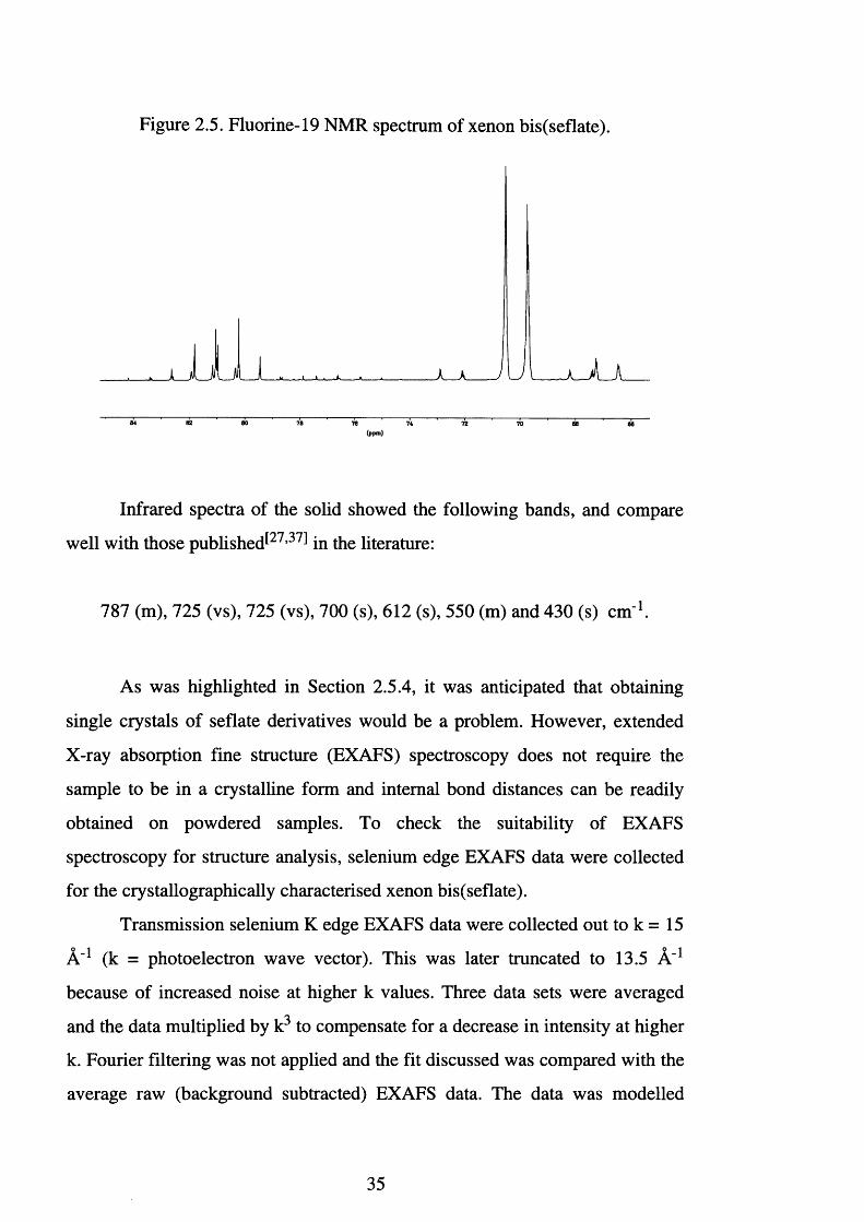
Figure 2.5. Fluorine-19 NMR spectrum of xenon bis(seflate).
64 62 80 78 76 72 70 66 66
Infrared spectra of the solid showed the following bands, and compare
well with those published^27,37 ̂ in the literature:
787 (m), 725 (vs), 725 (vs), 700 (s), 612 (s), 550 (m) and 430 (s) cm '1.
As was highlighted in Section 2.5.4, it was anticipated that obtaining
single crystals of seflate derivatives would be a problem. However, extended
X-ray absorption fine structure (EXAFS) spectroscopy does not require the
sample to be in a crystalline form and internal bond distances can be readily
obtained on powdered samples. To check the suitability of EXAFS
spectroscopy for structure analysis, selenium edge EXAFS data were collected
for the crystallographically characterised xenon bis(seflate).
Transmission selenium K edge EXAFS data were collected out to k = 15
A'1 (k = photoelectron wave vector). This was later truncated to 13.5 A'1 because of increased noise at higher k values. Three data sets were averaged
and the data multiplied by k3 to compensate for a decrease in intensity at higher
k. Fourier filtering was not applied and the fit discussed was compared with the
average raw (background subtracted) EXAFS data. The data was modelled
35
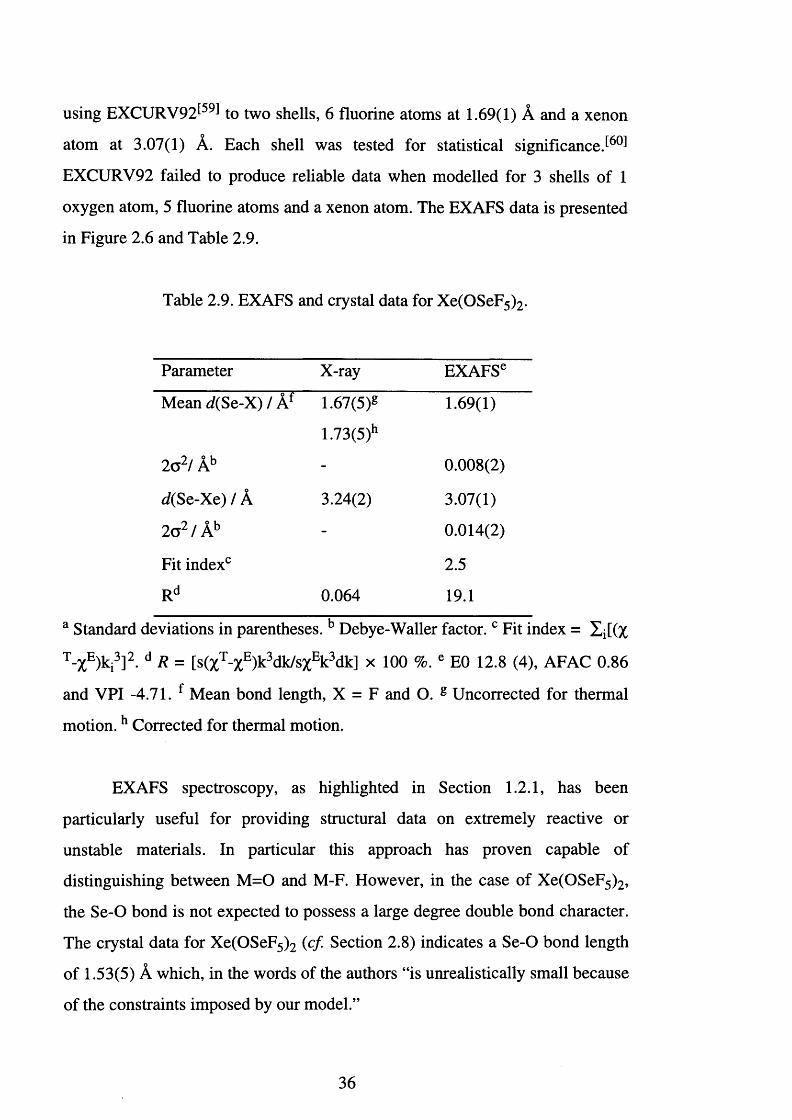
using EXCURV92t59] to two shells, 6 fluorine atoms at 1.69(1) A and a xenon
atom at 3.07(1) A. Each shell was tested for statistical significance
EXCURV92 failed to produce reliable data when modelled for 3 shells of 1
oxygen atom, 5 fluorine atoms and a xenon atom. The EXAFS data is presented
in Figure 2.6 and Table 2.9.
Table 2.9. EXAFS and crystal data for Xe(OSeF5)2.
Parameter X-ray EXAFSe
Mean rf(Se-X) / Af 1.67(5)g
1.73(5)h
1.69(1)
2o2/ Ab - 0.008(2)
d(Se-Xe) / A 3.24(2) 3.07(1)
2o2/Ab - 0.014(2)
Fit index0 2.5
Rd 0.064 19.1
a Standard deviations in parentheses. b Debye-Waller factor. c Fit index = Xi[(%
T - X E ) k i 3 ] 2 . d R = [s(%T-%E)k3 dk/s%Ek 3 dk] x 100 %. e E0 12.8 (4), AFAC 0.86
and VPI -4.71. f Mean bond length, X = F and O. g Uncorrected for thermal
m otion.h Corrected for thermal motion.
EXAFS spectroscopy, as highlighted in Section 1.2.1, has been
particularly useful for providing structural data on extremely reactive or
unstable materials. In particular this approach has proven capable of
distinguishing between M =0 and M-F. However, in the case of Xe(OSeF5)2,
the Se-O bond is not expected to possess a large degree double bond character.
The crystal data for Xe(OSeF5 ) 2 (c f Section 2.8) indicates a Se-O bond length
of 1.53(5) A which, in the words of the authors “is unrealistically small because
of the constraints imposed by our model.”
36
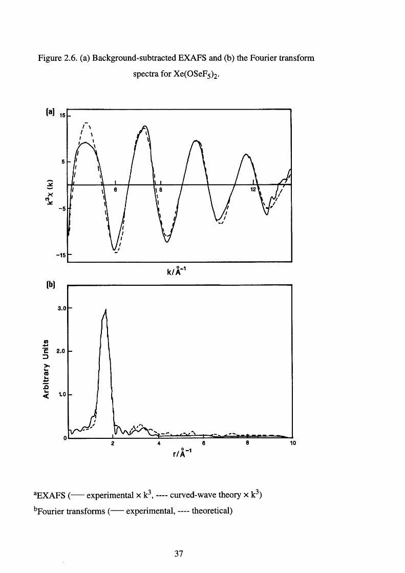
Figure 2.6. (a) Background-subtracted EXAFS and (b) the Fourier transform
spectra for Xe(OSeF5)2.
M
Xco-5
-15
* -1k /A ‘lb]
3.0
C 2.0 D>.> -(0k .13< 1.0
0 - 1 r /A
aEXAFS ( experimental x k3, curved-wave theory x k3)
bFourier transforms ( experimental, — theoretical)
37
In comparison, a microwave spectroscopic study of SeOF2 6̂1 ̂
determined the Se= 0 distance to be 1.576(3) A, and in Section 3.13, the Br= 0
distance for Cs[BrOF4], which should be similar, was calculated to be 1.58(1)
A. Therefore, the Se-O distance of 1.53(5) A, determined using X-ray
crystallography, is too low, and the inability of EXAFS spectroscopy to
distinguish between the oxygen and fluorine atoms is a reflection of the
similarities in the size of oxygen and fluorine atoms, and the Se-O and Se-F
bond lengths. Therefore, the first shell of six fluorine atoms represents the
average Se-F and Se-O bond lengths present with in the seflate ligand. The
value of 1.69(1) A is in satisfactory agreement with the crystallographic study
where the average Se-O and Se-F bond distances are calculated to be 1.67(5)
(uncorrected) and 1.73(5) A (corrected for thermal motion).
A covalent interaction between the seflate anion and the xenon atom is
expected to result in a large Xe-O-Se angle. As outlined in Section 2.5.1, xenon
bis(seflate) definitely possesses some covalent character, Aab = -11.1, c f
[N 0 2 ][0SeF5] Aab = -36.8 and F5 SeOSeF5 Aab = 13.3. Covalent interactions
in the case of F5 XOXF5 (X = S, Se or Te, Section 2.6) were observed to result
in an increase in the oxygen bridging angle. The Xe-Se distance determined
using X-ray crystallography was 3.24(2) A, whereas, the value obtained using
EXAFS spectroscopy was 3.07(1) A. The bond lengths are significantly
different, and the shorter value obtained using EXAFS spectroscopy implies a
reduced Xe-O-Se angle of 109(5)° {cf 125(2)° in the X-ray structure). To
determine the bond angle it was necessary to assume a Se-O distance of 1.6-
1.69 A, as already discussed the Se-O distance of 1.53(5) A (X-ray structure) is
too short. As can be seen the discrepancy in the Xe-Se distance results in a
significant decrease in the Xe-O-Se angle. The lack of information makes a
detailed discussion inappropriate, however, with the continued expansion of
this area and the use of EXAFS, 19F NMR and vibrational spectroscopies, it
may in the future, be possible to establish a trend between bridging angles and
the degree of covalent nature.
38
2.10. The Reaction Between [Re2 (CO)io] and Xe(OSeF5 )2 -
The reaction of [Re2 (CO)10] with dilute fluorine-nitrogen mixtures in a
flow system leads only to the formation of ReF6.[62] Although, the carbonyl
halides [Re(CO)5 X] (X = chlorine, bromine or iodine) are known,![63] w as
thought unlikely that fluorine would stabilise the Re (I) oxidation state as it has
no available orbitals to permit n back bonding. However, XeF2 in solution is a
mild fluorinating agent and reaction of xenon difluoride, XeF2, with
[Re2 (CO)10] in anhydrous HF or Genetron 113, does lead to the low-valent
rhenium fluoride complex [Re(CO)5F ReF5] ̂ (Eqn. 2.23). If the Xe and CO
are not vented from the reaction then the ionic [Re(CO ) 6 ReF6] is produced.
[Re2 (CO)10] + 3 XeF2 -> [Re(CO)5F ReF5] + 5 CO + 3 Xe Eqn. 2.23.
The reaction between [Re2 (CO)10] and Xe(OTeF5 ) 2 also leads to a low-
valent metal teflate complex [Re(CO)5 (OTeF5)] ̂ (Eqn. 2.24) and the same
complex is formed by the reaction of [Re(CO)5 (CH3)] with HOTeF5.
[Re2 (CO)10] + Xe(OTeF5 ) 2 2 [Re(CO)5 (OTeF5)] + Xe Eqn. 2.24.
In an attempt to prepare a Re (I) seflate derivative the reaction between
[Re2 (CO)10] and Xe(OSeF5 ) 2 was investigated. Colourless [Re2 (CO)10] was
solvated in dichloromethane and then decanted at -78°C on to an equimolar
quantity of Xe(OSeF5)2. No immediate reaction occurred but, upon warming to
0°C, a steady reaction commenced and a gas was evolved. Analysis of the gas
by infrared spectroscopy showed that no carbon monoxide was present, and
thus the gas was presumed to be xenon. The reaction continued for about three
39
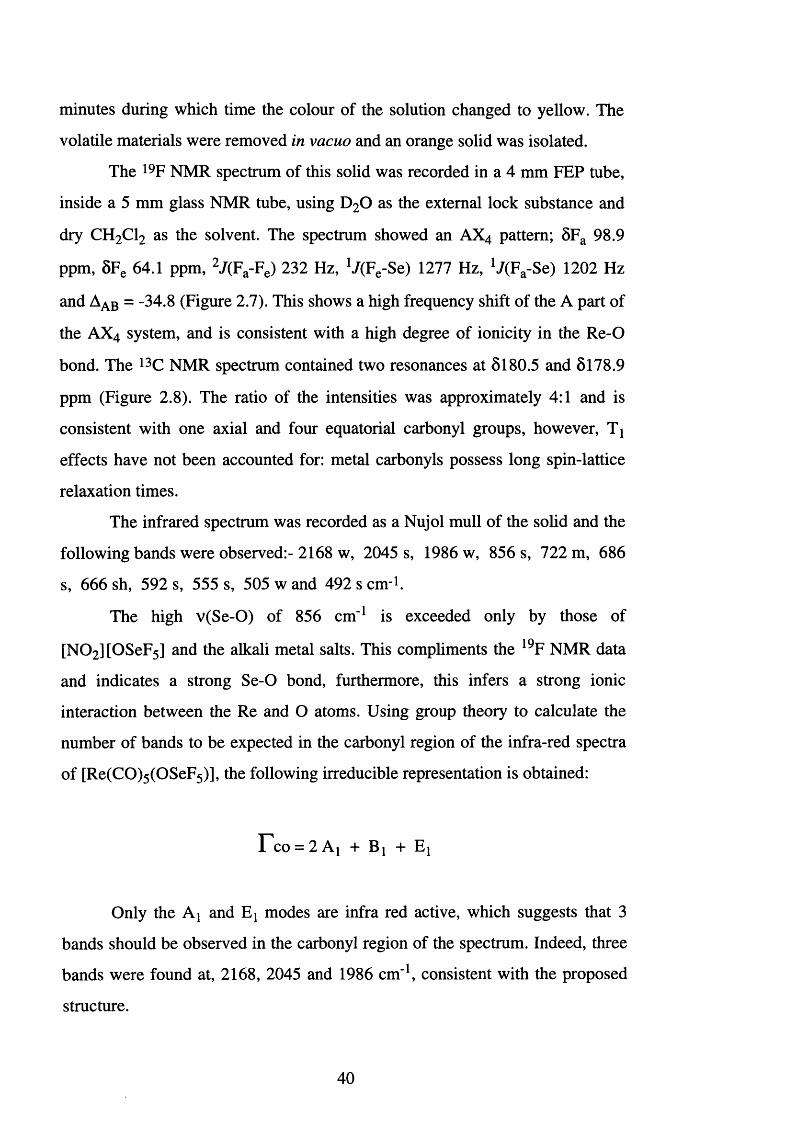
minutes during which time the colour of the solution changed to yellow. The
volatile materials were removed in vacuo and an orange solid was isolated.
The 19F NMR spectrum of this solid was recorded in a 4 mm FEP tube,
inside a 5 mm glass NMR tube, using D20 as the external lock substance and
dry CH 2 C12 as the solvent. The spectrum showed an AX4 pattern; 5Fa 98.9
ppm, 5Fe 64.1 ppm, 2 /(F a-Fe) 232 Hz, V(Fe-Se) 1277 Hz, *7(Fa-Se) 1202 Hz
and Aab = -34.8 (Figure 2.7). This shows a high frequency shift of the A part of
the AX 4 system, and is consistent with a high degree of ionicity in the Re-O
bond. The 13C NMR spectrum contained two resonances at 5180.5 and 5178.9
ppm (Figure 2.8). The ratio of the intensities was approximately 4:1 and is
consistent with one axial and four equatorial carbonyl groups, however, Tj
effects have not been accounted for: metal carbonyls possess long spin-lattice
relaxation times.
The infrared spectrum was recorded as a Nujol mull of the solid and the
following bands were observed:- 2168 w, 2045 s, 1986 w, 856 s, 722 m, 6 8 6
s, 6 6 6 sh, 592 s, 555 s, 505 w and 492 s c n r1.
The high v(Se-O) of 856 cm " 1 is exceeded only by those of
[N 0 2 ][0S eF 5] and the alkali metal salts. This compliments the 19F NMR data
and indicates a strong Se-O bond, furthermore, this infers a strong ionic
interaction between the Re and O atoms. Using group theory to calculate the
number of bands to be expected in the carbonyl region of the infra-red spectra
of [Re(CO)5 (OSeF5)], the following irreducible representation is obtained:
r*co = 2 A1 + Bj + Ej
Only the A] and Ej modes are infra red active, which suggests that 3
bands should be observed in the carbonyl region of the spectrum. Indeed, three
bands were found at, 2168, 2045 and 1986 cm '1, consistent with the proposed
structure.
40
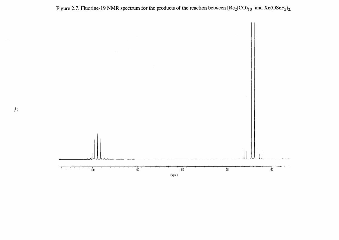
Figure 2.7. Fluorine-19 NMR spectrum for the products of the reaction between [Re2(CO)10] and Xe(OSeF5)2
(ppm)

Figure 2.8. Carbon-13 NMR spectrum for the product of the
reaction between [Re^CO)!0] and Xe(OSeF5 ) 2
182.5 181.5182.0 181.0 180.5 180.0 179.5 179.0 178.5 178.0
(ppm)
The material proved sufficiently stable to obtain an electron-impact mass
spectrum. The correct isotope pattern was obtained for the parent ion
[Re(CO)5 (OSeF5)]+, m/z 518 (for 185Re and 8 2 Se) (Figure 2.9). Accurate mass
spectrometry was used to unequivocally identify the presence of
[Re(CO)5 (OSeF5)], and no fragments derived from loss of CO, F or seflate
were observed.
The work carried out in Section 2.9 established that the Se edge EXAFS
data for Xe(OSeF5 ) 2 was satisfactory, and final analysis of [Re(CO)5 (OSeF5)]
was therefore attempted by EXAFS spectroscopy.
Transmission selenium K edge EXAFS data were collected out to k = 15
A'1 (k = photoelectron wave vector). This was later truncated to 12.5 A-1 because of increased noise at higher k values. Three data sets were averaged
and the data multiplied by k 3 to compensate for a decrease in intensity at higher
42
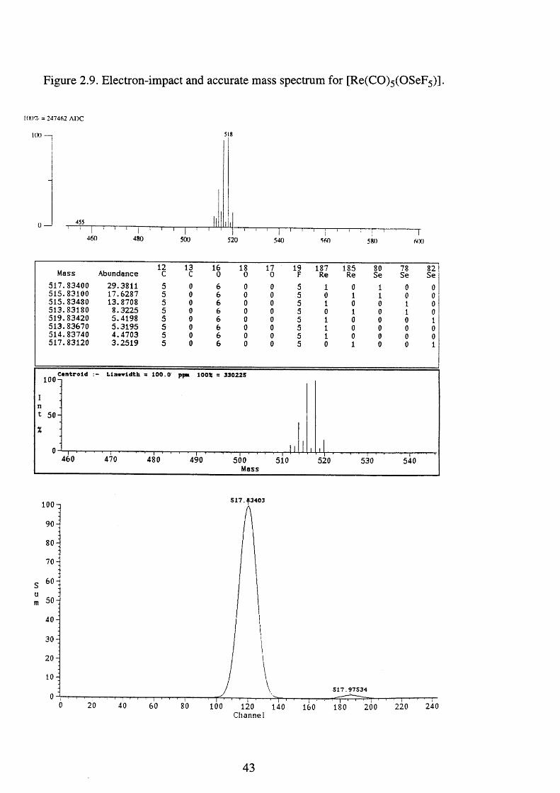
Figure 2.9. Electron-impact and accurate mass spectrum for [Re(CO)5(OSeF5)].
!(X)% = 247462 A D C
l(X) —
0 —
518
455
460 480 500 520 540 580 6(X)
12 13 16 18 17 19 187 185 80 78 82Mass Abundance C C 0 0 0 F Re Re Se Se Se517.83400 29.3811 5 0 6 0 0 5 1 0 1 0 0515.83100 17.6287 5 0 6 0 0 5 0 1 1 0 0515.83480 13.8708 5 0 6 0 0 5 1 0 0 1 0513.83180 8.3225 5 0 6 0 0 5 0 1 0 1 0519.83420 5.4198 5 0 6 0 0 5 1 0 0 0 1513.83670 5.3195 5 0 6 0 0 5 1 0 0 0 0514.83740 4.4703 5 0 6 0 0 5 1 0 0 0 0517.83120 3.2519 5 0 6 0 0 5 0 1 0 0 1
Centroid10 0 -1
I nt 50 H
Llnowldth = 100.0 ppn lOOX = 330225
460 470 480 490 500Mass
510 520 530 540
517.83403lOOn
9 0-
80-
70-
s 60ium 50 -
4 0-
30^2 0 -
1 0 -
5 1 7 . 9 7 5 3 4
60 100 240120Channel
220140 160 180 200
43
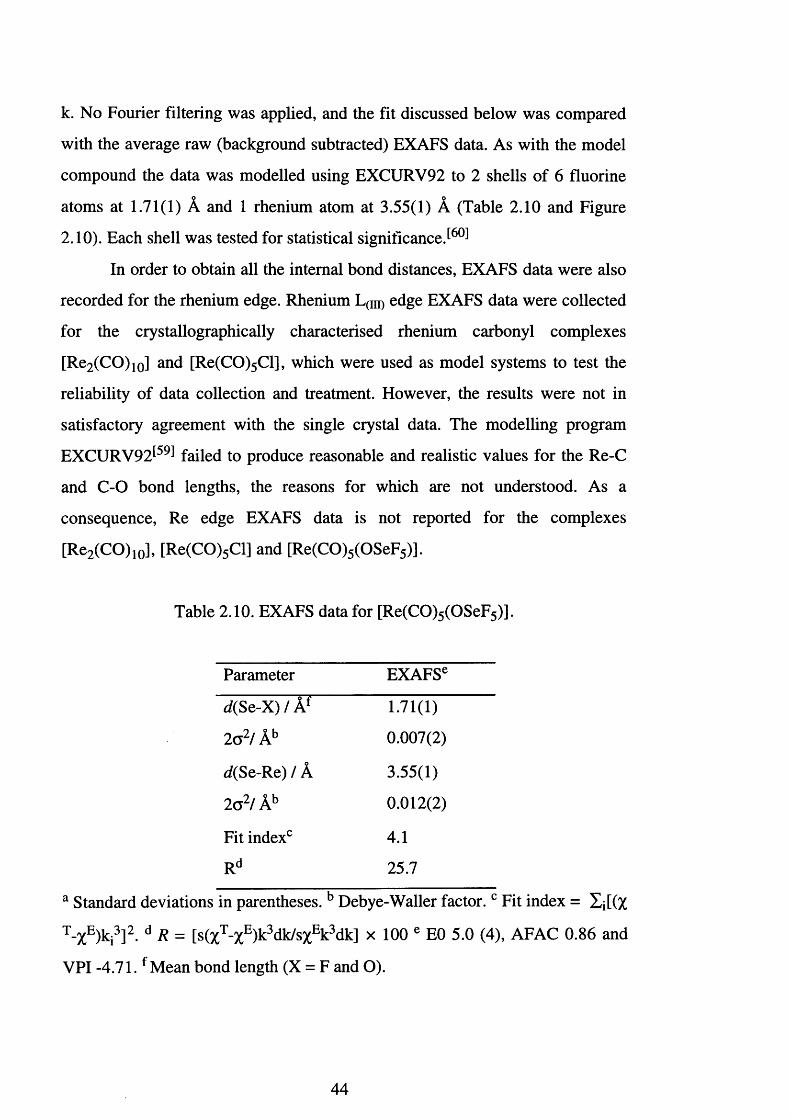
k. No Fourier filtering was applied, and the fit discussed below was compared
with the average raw (background subtracted) EXAFS data. As with the model
compound the data was modelled using EXCURV92 to 2 shells of 6 fluorine
atoms at 1.71(1) A and 1 rhenium atom at 3.55(1) A (Table 2 . 1 0 and Figure
2.10). Each shell was tested for statistical significance J60]
In order to obtain all the internal bond distances, EXAFS data were also
recorded for the rhenium edge. Rhenium L(IIi) edge EXAFS data were collected
for the crystallographically characterised rhenium carbonyl complexes
[Re2 (CO)10] and [Re(CO)5 Cl], which were used as model systems to test the
reliability of data collection and treatment. However, the results were not in
satisfactory agreement with the single crystal data. The modelling program
EXCURV92^59 ̂ failed to produce reasonable and realistic values for the Re-C
and C-O bond lengths, the reasons for which are not understood. As a
consequence, Re edge EXAFS data is not reported for the complexes
[Re2 (CO)10], [Re(CO)5 Cl] and [Re(CO)5 (OSeF5)].
Table 2.10. EXAFS data for [Re(CO)5 (OSeF5)].
Parameter EXAFSe
d(Se-X) / Af 1.71(1)
l a 2/ Ab 0.007(2)
rf(Se-Re) / A 3.55(1)
l a 2/ Ab 0 .0 1 2 (2 )
Fit indexc 4.1
Rd 25.7
a Standard deviations in parentheses. b Debye-Waller factor. c Fit index = Xi[(%
T-XE)ki3]2. d R = [s(%T-%E)k3 dk/s%Ek3 dk] x 100 e E0 5.0 (4), AFAC 0.86 and
VPI -4 .71 .f Mean bond length (X = F and O).
44
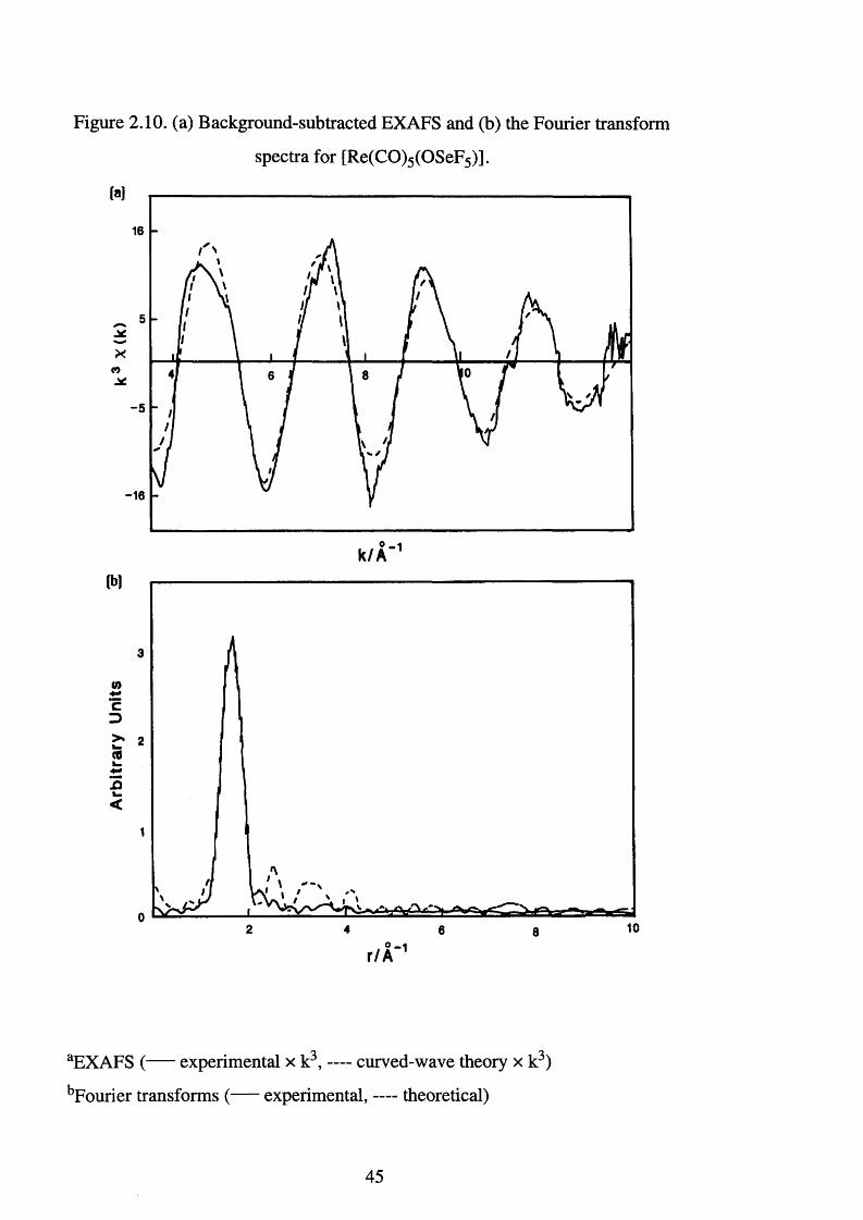
Figure 2.10. (a) Background-subtracted EXAFS and (b) the Fourier transform
spectra for [Re(CO)5 (OSeF5)].
-5
-16
(b)
3
2
1
0
O
r / A 1
aEXAFS ( experimental x k3, — curved-wave theory x k3)
bFourier transforms ( experimental, — theoretical)
45

The spectroscopic data presented in this section conclusively shows that
the reaction of [Re2 (CO)10] with Xe(OSeF5 ) 2 produces [Re(CO)5 (OSeF5)].
Mass spectrometry showed the presence of the parent ion [Re(CO)5 (OSeF5)]+
and infrared and 19F NMR spectroscopies indicated that the interaction between
the seflate group and the rhenium centre is highly ionic in nature. This is to be
expected when one considers the high electronegativity of the seflate group and
the low oxidation state of the rhenium carbonyl moiety [Re(CO)5]+. Hence, it
has been demonstrated, for the first time, that the seflate ligand is compatible
with low valent metal carbonyl complexes. The Se edge EXAFS data collection
and treatment was satisfactory, and a comparison of the Re-Se distance (3.55
A) to that of the Xe-Se distance (3.07 A) in Xe(OSeF5)2, highlights the
covalent nature present in the Xe-seflate bond. The inability to collect and
interpret the Re edge EXAFS data is unfortunate because it prohibits the
calculation of the bridging Se-O-Re bond angle.
2.11. The Reaction Between [Mn2(CO)io] and Xe(OSeF5 )2 -
A survey of the literature indicates that F2 and XeF2 do not react with
[Mn2 (CO)10] to produce any stable carbonyl fluorides. The reaction between
AgF and [Mn(CO)5 Br] was originally reported to yield the dimer
[{Mn(CO)4 F}2] or, with excess of AgF, [Mn(CO)3 F3].t65 ̂ However,
reinvestigation by Horn et. alS66̂ revealed that the overall reaction produced
four structurally related clusters, [Mn4 (CO)1 2 Fx(OH)4_x] (x = 0-4). The
hydroxyl contamination resulted from moisture within the system which is
extremely difficult to remove (N.B. AgF is hydrated). This reaction
demonstrates the intrinsic differences between fluorine and the heavier halides,
in which [Mn(CO)5 X] (X=C1, Br and I) are all stable solids.
Recent work carried out at Leicester^ has shown that [Mn2 (CO)10] will
react with xenon bis(teflate) to produce manganese pentacarbonyl teflate,
46
[Mn(CO)5 (OTeF5)]; which is, however, unstable in the presence of excess of
Xe(OTeF5)2. A second paramagnetic species is also formed, and the infra-red
data point towards the product being a d5 Mn (II) species, believed to be cis-
[Mn(CO)4 (OTeF5)2]. Any further excess of Xe(OTeF5 ) 2 leads to
decomposition and no identifiable products. Manganese pentacarbonyl teflate,
[Mn(CO)5 (OTeF5)], can also be produced by a methyl exchange reaction using
teflic acid^9,10 ̂ (Eqn. 2.25).
[MeMn(CO)5] + HOTeF5 -> [Mn(CO)5 (OTeF5)] + CH 4 Eqn. 2.25.
The 19F NMR and infra-red spectral data for the products formed using
the two different routes match exactly. These data, along with a crystal
structure, offers conclusive evidence for the formation of [Mn(CO)5 (OTeF5)]
from the reaction between Xe(OTeF5 ) 2 and [Mn2 (CO)10]. In view of these
results the synthesis of [Mn(CO)5 (OSeF5)] was attempted via the reaction
between [Mn2 (CO)10] and Xe(OSeF5)2.
Manganese carbonyl dimer, [Mn2 (CO)10], was dissolved in
dichloromethane to give a yellow solution. The solution was decanted on to an
equimolar quantity of Xe(OSeF5)2, at -78°C. No immediate reaction occurred,
but as the solution reached room temperature a vigorous reaction commenced
which necessitated cooling with an acetone / C 0 2 bath. This cycle of
warming and quenching was repeated until the reaction appeared to be
complete. Analysis of the gas produced by infrared spectroscopy showed no
carbon monoxide to be present, and it was inferred to be xenon. The solution
changed to orange over the course of the reaction {ca. five minutes), and when
the reaction was complete all volatile materials were removed to yield an
orange solid.
47
The 19F NMR spectrum of this solid was recorded in a 4 mm FEP tube
using D20 as the external lock substance and dichloromethane as the solvent.
The spectrum showed an AX 4 pattern: 8 Fa 101.7 ppm, 8 Fe 69.2 ppm, 2 /(F a-Fe)
227 Hz , VCFg-Se) 1265 Hz and Aab = -32.5 (Figure 2.12). No 77Se satellites
were resolved for Fa. The 13C NMR was recorded and this showed a single
broad resonance at 5204.6 ppm, Avi/z 8 6 Hz c f [Re(CO)5 (OSeF5)] AVi/ 2 7 Hz
(Figure 2.13).
The 19F and 13C NMR spectra were poorly resolved compared with
those for the [Re(CO)5 (OSeF5)] experiment. There may be two possible
explanations:-
1) There may be stereochemical fluxionality within this system.
However, running the NMR experiments at low temperature gave little
improvement in the spectral resolution.
2) The manganese 55 nucleus has I = 5/2 and is 100% abundant. When I
is greater than a Vi the nucleus possesses an electric quadrupolar moment, Q,
which is due to a non-spherical charge distribution J67 ̂ This can interact with
electric field gradients arising from electric charge distributions within the
molecule. This interaction provides a means by which the nucleus can relax
rapidly, and consequently can dramatically affect NMR spectra.
In the 19F NMR spectrum the axial fluorine, Fa, showed a significant
shift towards high frequency, and the Aab value of -32.5, demonstrates that the
bonding between manganese and oxygen possesses a large degree of ionic
character (c f Table 2.4).
The infra-red spectrum was recorded as a Nujol mull of the solid and
showed the following absorptions:- 2164 s, 2064 s, 2029 s, 864 s, 683 s, 624 s,
593 w and 543 s.
48
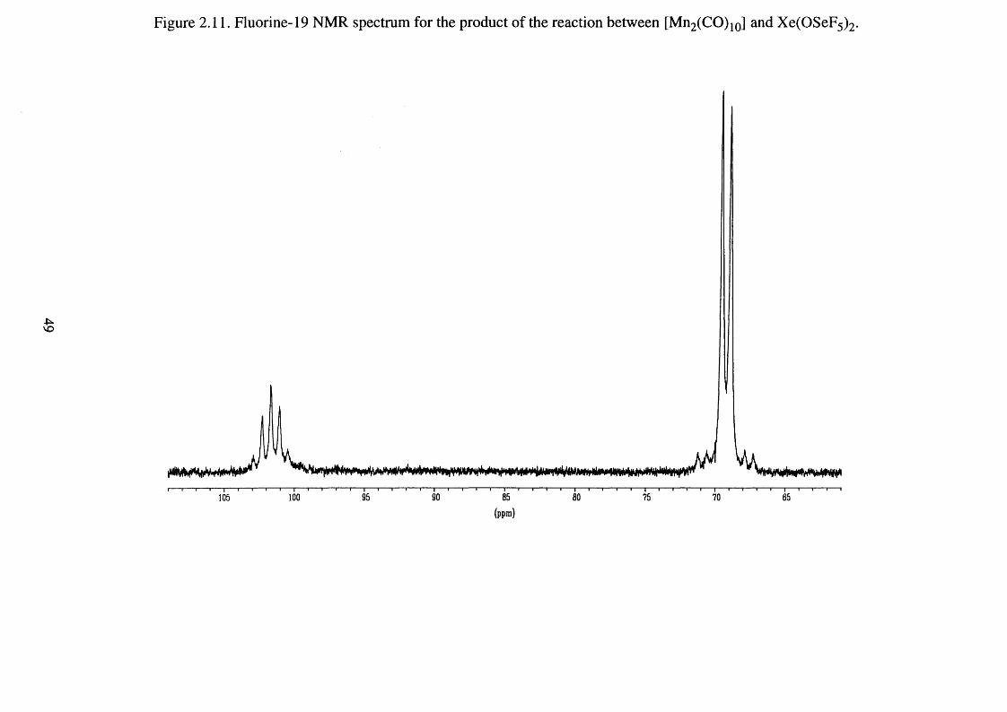
Figure 2.11. Fluorine-19 NMR spectrum for the product of the reaction between [Mn2(CO)10] and Xe(OSeF5)2.
100
(ppm )
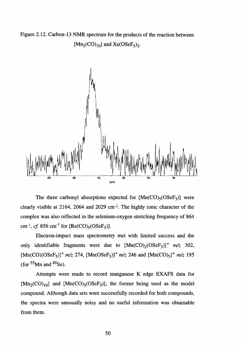
Figure 2.12. Carbon-13 NMR spectrum for the products of the reaction between
[Mn2 (CO)10] and Xe(OSeF5)2.
208 198206 202 200
The three carbonyl absorptions expected for [Mn(CO)5 (OSeF5)] were
clearly visible at 2164, 2064 and 2029 cm-1. The highly ionic character of the
complex was also reflected in the selenium-oxygen stretching frequency of 864
cm-i, cf. 856 cm ' 1 for [Re(CO)5 (OSeF5)].
Electron-impact mass spectrometry met with limited success and the
only identifiable fragments were due to [Mn(CO)2 (OSeF5)]+ m/z 302,
[Mn(CO)(OSeF5)]+ m/z 274, [Mn(OSeF5)]+ m/z 246 and [Mn(CO)5]+ m/z 195
(for 55Mn and 8 0 Se).
Attempts were made to record manganese K edge EXAFS data for
[Mn2 (CO)10] and [Mn(CO)5 (OSeF5)], the former being used as the model
compound. Although data sets were successfully recorded for both compounds,
the spectra were unusually noisy and no useful information was obtainable
from them.
50
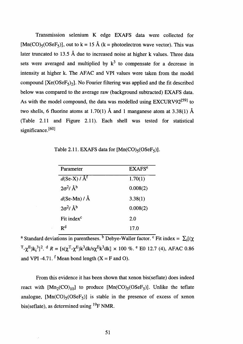
Transmission selenium K edge EXAFS data were collected for
[Mn(CO)5 (OSeF5)], out to k = 15 A (k = photoelectron wave vector). This was
later truncated to 13.5 A due to increased noise at higher k values. Three data
sets were averaged and multiplied by k 3 to compensate for a decrease in
intensity at higher k. The AFAC and VPI values were taken from the model
compound [Xe(OSeF5)2] . No Fourier filtering was applied and the fit described
below was compared to the average raw (background subtracted) EXAFS data.
As with the model compound, the data was modelled using EXCURV92^59 ̂ to
two shells, 6 fluorine atoms at 1.70(1) A and 1 manganese atom at 3.38(1) A (Table 2.11 and Figure 2.11). Each shell was tested for statistical
significance
Table 2.11. EXAFS data for [Mn(CO)5 (OSeF5)].
Parameter EXAFSe
d(Sc-X) / Af 1.70(1)
2 c 2/ Ab 0.008(2)
</(Se-Mn) / A 3.38(1)
2 a 2/ Ab 0.008(2)
Fit index0 2 . 0
Rd 17.0
a Standard deviations in parentheses. b Debye-Waller factor. c Fit index = XjtQc
T-XE)ki3]2. d R = [s(%T-%E)k3 dk/s%Ek3 dk] x 100 %. e E0 12.7 (4), AFAC 0.86
and VPI -4 .71 .f Mean bond length (X = F and O).
From this evidence it has been shown that xenon bis(seflate) does indeed
react with [Mn2 (CO)10] to produce [Mn(CO)5 (OSeF5)]. Unlike the teflate
analogue, [Mn(CO)5 (OSeF5)] is stable in the presence of excess of xenon
bis(seflate), as determined using 19F NMR.
51
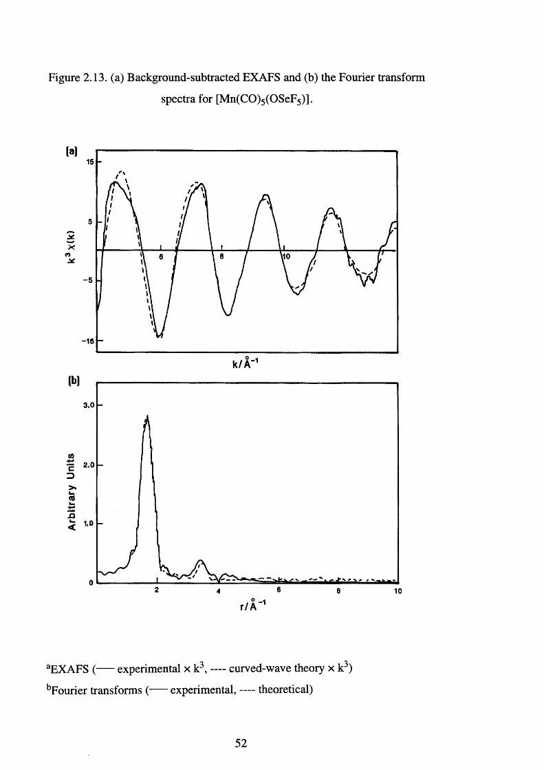
Figure 2.13. (a) Background-subtracted EXAFS and (b) the Fourier transform
spectra for [Mn(CO)5 (OSeF5)].
(a)
*CO
-5
-15
(b)
3.0
CO
cD>.i _C 6i —
6 82 104
r / A 1
aEXAFS ( experimental x k3, — curved-wave theory x k3)
bFourier transforms ( experimental, — theoretical)
52
2.12. The Reaction Between [Ru(CO)3(PPh3)2] and Xe(OSeF5)2.
As a result of the successes with similar systems, numerous reactions
have been undertaken between XeF2 and a range of ruthenium (0 )
complexes.[68,69̂ Of these reactions, that between [Ru(CO)3 (PPh3)2] and XeF2
has been the most fully investigated. The stepwise oxidative addition of xenon
difluoride to [Ru(CO)3 (PPh3)2] occurs readily at low temperature. The
mechanism ^6 9 , 7 0 1 involves oxidation by [XeF]+, then nucleophilic attack of a
fluoride anion at the co-ordinated CO, followed ultimately by elimination of
carbon monoxide to yield the stable octahedral complex, [OC-6-
13][RuF2(CO)2(PPh3)2] (Eqn. 2.26).
XeF2 + [Ru(CO)3 (PPh3)2] -> [RuF2 (CO)2 (PPh3)2] + Xe + CO Eqn. 2.26.
The products and intermediates formed in this reaction were
characterised using multinuclear NMR and infrared spectroscopy, and X-ray
crystallography. Although the reaction between [Ru(CO)3 (PPh3)2] and
Xe(OTeF5 ) 2 has also been r e p o r t e d t h e evidence for the formation of the
analogous [Ru(CO)2 (PPh3 )2 (OTeF5)2] was not conclusive.
To establish whether the seflate group and low-valent metal-phosphine
carbonyl compounds are compatible, the reaction between [Ru(CO)3 (PPh3)2]
and Xe(OSeF5 ) 2 was investigated.
Pale yellow [Ru(CO)3 (PPh3)2] was dissolved in dichloromethane and
decanted, at -78°C, on to an equimolar quantity of Xe(OSeF5)2. On warming to
room temperature a reaction commenced, as evidenced by the evolution of a
gas, and continued at a steady rate for 10 minutes. Analysis of the gas by
infrared spectroscopy showed the presence of carbon monoxide [v(CO) at 2143
cm '1]. All the volatile materials were removed and a brown solid was isolated.
53
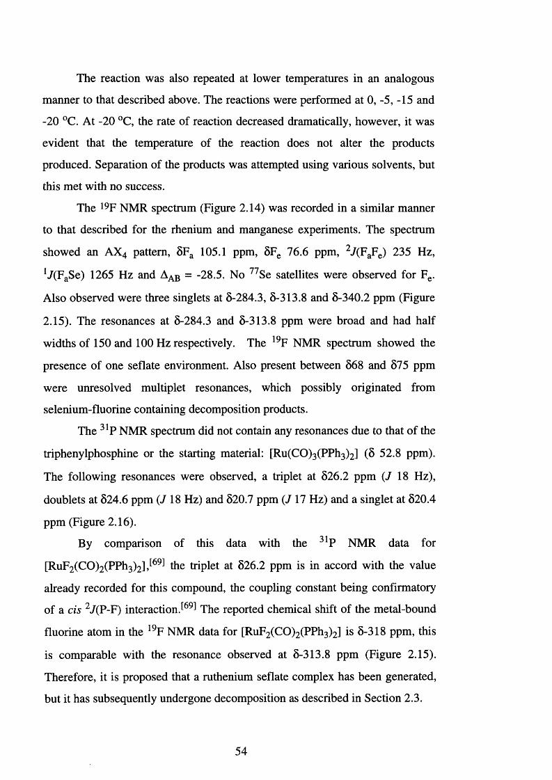
The reaction was also repeated at lower temperatures in an analogous
manner to that described above. The reactions were performed at 0, -5, -15 and
-20 °C. At -20 °C, the rate of reaction decreased dramatically, however, it was
evident that the temperature of the reaction does not alter the products
produced. Separation of the products was attempted using various solvents, but
this met with no success.
The 19F NMR spectrum (Figure 2.14) was recorded in a similar manner
to that described for the rhenium and manganese experiments. The spectrum
showed an AX4 pattern, 5Fa 105.1 ppm, 8 Fe 76.6 ppm, 2 7(FaFe) 235 Hz,
lJ(FaSe) 1265 Hz and Aab = -28.5. No 77Se satellites were observed for Fe.
Also observed were three singlets at 5-284.3, 8-313.8 and 5-340.2 ppm (Figure
2.15). The resonances at 8-284.3 and 5-313.8 ppm were broad and had half
widths of 150 and 100 Hz respectively. The 19F NMR spectrum showed the
presence of one seflate environment. Also present between 8 6 8 and 575 ppm
were unresolved multiplet resonances, which possibly originated from
selenium-fluorine containing decomposition products.
The 31P NMR spectrum did not contain any resonances due to that of the
triphenylphosphine or the starting material: [Ru(CO)3 (PPh3)2] ( 8 52.8 ppm).
The following resonances were observed, a triplet at 526.2 ppm (7 18 Hz),
doublets at 824.6 ppm (718 Hz) and 520.7 ppm (7 17 Hz) and a singlet at 820.4
ppm (Figure 2.16).
By comparison of this data with the 31P NMR data for
[RuF2 (CO)2 (PPh3)2],[69] the triplet at 826.2 ppm is in accord with the value
already recorded for this compound, the coupling constant being confirmatory
of a cis 2 7(P-F) interaction J69 ̂ The reported chemical shift of the metal-bound
fluorine atom in the 19F NMR data for [RuF2 (CO)2 (PPh3)2] is 5-318 ppm, this
is comparable with the resonance observed at 5-313.8 ppm (Figure 2.15).
Therefore, it is proposed that a ruthenium seflate complex has been generated,
but it has subsequently undergone decomposition as described in Section 2.3.
54
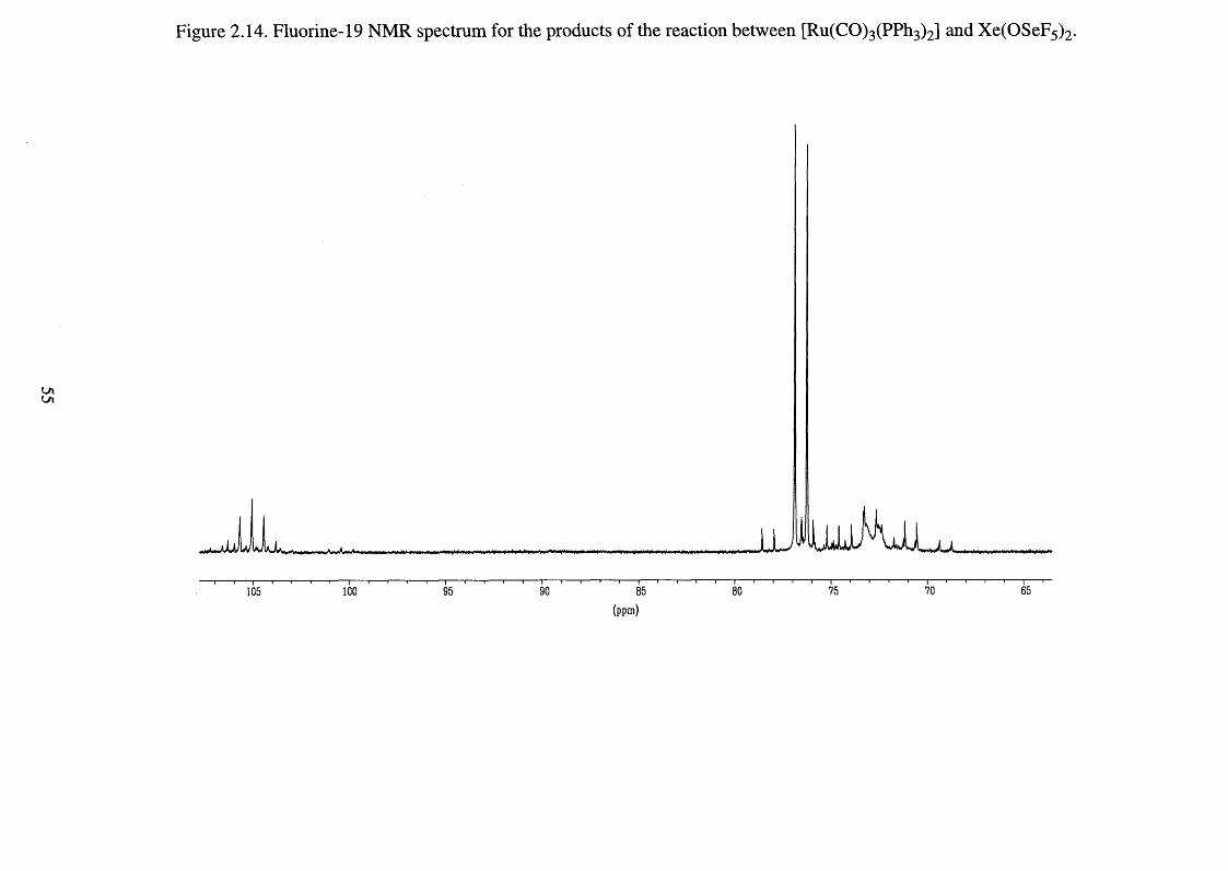
Figure 2.14. Fluorine-19 NMR spectrum for the products of the reaction between [Ru(CO)3(PPh3)2] and Xe(OSeF5)2.
100105
(ppm )
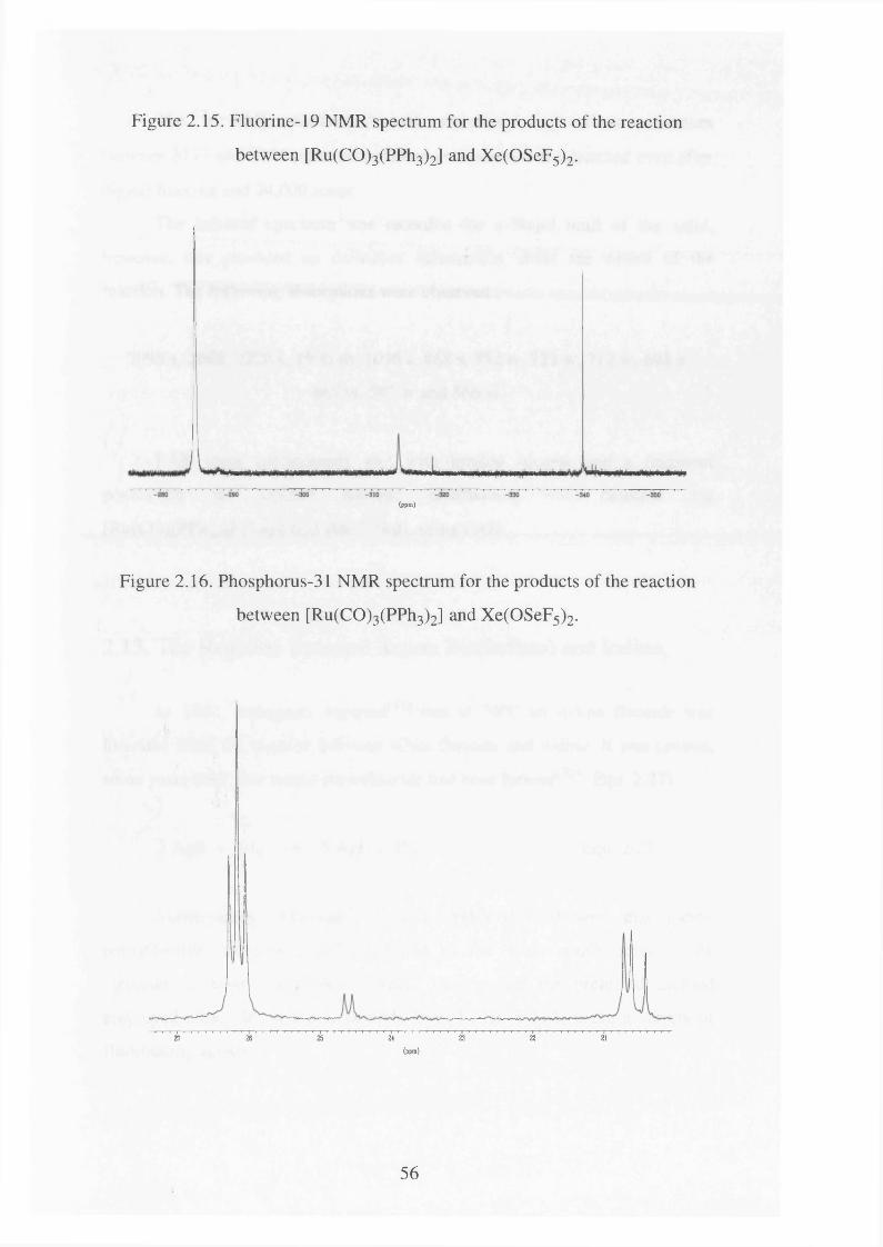
Figure 2.15. Fluorine-19 NMR spectrum for the products of the reaction
between [Ru(CO)3(PPh3)2] and Xe(OSeF5)2.
(ppm)
Figure 2.16. Phosphorus-31 NMR spectrum for the products of the reaction
between [Ru(CO)3(PPh3)2] and Xe(OSeF5)2.
27 26 25 24 23 22 21
(ppm)
56
The 13C NMR spectrum showed only phenyl ring carbon resonances
between 8127 and 8136 ppm; no carbonyl resonances were detected even after
digital filtering and 24,000 scans.
The infrared spectrum was recorded for a Nujol mull of the solid,
however, this provided no definitive information about the nature of the
reaction. The following absorptions were observed
2098 s, 2069, 2220 s, 1996 sh, 1096 s, 8 6 8 s, 752 w, 723 w, 712 w, 698 s,
667 w, 597 w and 566 w.
FAB mass spectrometry met with limited success and a fragment
possessing the correct isotopic distribution was detected for
[Ru(CO)(PPh3 )2 F]+ m/z 673 (for 1 0 2 Ru), using FAB.
2.13. The Reaction Between Xenon Bis(Seflate) and Iodine.
In 1862, Kammerer reported^7 ̂ that at 70°C an iodine fluoride was
liberated from the reaction between silver fluoride and iodine. It was proven,
some years later, that iodine pentafluoride had been formed^72! (Eqn. 2.27).
5 AgF + 3 I2 -> 5 Agl + IF5 Eqn. 2.27.
Subsequently, Moissan^73,74 ̂ and Prideaux^75 ̂ showed that iodine
pentafluoride could be readily prepared by the direct combination of the
elements at room temperature. Whilst this is still the preferred method
employed today, IF5 is also accessible from I2, HI or I2 0 5 using a variety of
fluorinating agents.
57
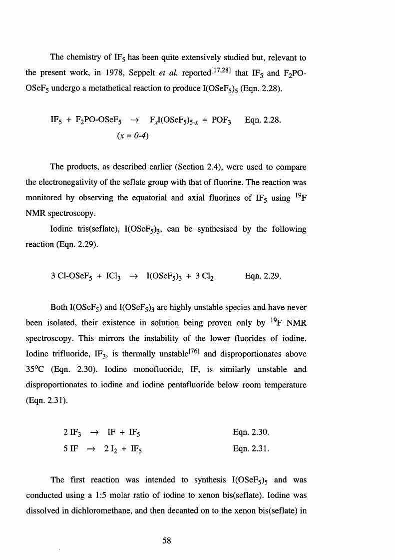
The chemistry of IF5 has been quite extensively studied but, relevant to
the present work, in 1978, Seppelt et al. reported1 1 7 ,2 8 1 that IF5 and F2 PO-
OSeF5 undergo a metathetical reaction to produce I(OSeF5 ) 5 (Eqn. 2.28).
IF5 + F2 PO-OSeF5 -> FjCI(OSeF5)5.JC + POF3 Eqn. 2.28.
(jc = 0-4)
The products, as described earlier (Section 2.4), were used to compare
the electronegativity of the seflate group with that of fluorine. The reaction was
monitored by observing the equatorial and axial fluorines of IF5 using 19F
NMR spectroscopy.
Iodine tris(seflate), I(OSeF5)3, can be synthesised by the following
reaction (Eqn. 2.29).
3 Cl-OSeF5 + IC13 -> I(OSeF5 ) 3 + 3 Cl2 Eqn. 2.29.
Both I(OSeF5) and I(OSeF5 ) 3 are highly unstable species and have never
been isolated, their existence in solution being proven only by 19F NMR
spectroscopy. This mirrors the instability of the lower fluorides of iodine.
Iodine trifluoride, IF3, is thermally unstable1 7 6 1 and disproportionates above
35°C (Eqn. 2.30). Iodine monofluoride, IF, is similarly unstable and
disproportionates to iodine and iodine pentafluoride below room temperature
(Eqn. 2.31).
The first reaction was intended to synthesis I(OSeF5 ) 5 and was
conducted using a 1:5 molar ratio of iodine to xenon bis(seflate). Iodine was
dissolved in dichloromethane, and then decanted on to the xenon bis(seflate) in
2 IF3 -> IF + IF5 Eqn. 2.30.
Eqn. 2.31.5 IF -> 2 I2 + IF5
58

a 4 mm FEP tube at 25°C. An immediate reaction commenced and continued,
at a steady rate, for 15 minutes. After this time no further evolution of a gas
was observed. The FEP tube was heat sealed for analysis by NMR
spectroscopy. A further sample was prepared in a similar manner, the solvent
was removed, and the yellow-orange liquid that remained was submitted for
mass spectral analysis.
The 19F NMR spectral data for the above reaction is summarised in
Table 2.12, and the spectra are shown in Figures 2.17-2.19. Only two AX 4
patterns were observed in the seflate region. A third AX4 pattern, and a singlet
with 77Se satellites were observed at lower frequency.
Table 2.12. Fluorine-19 NMR spectral data for the products of the reaction
between iodine and five molar equivalents of xenon bis(seflate).
8
ppm
2J (FaFe)
Hz
‘/(S e p ,)
Hz
9.5 (d)b 90 -
42.8 (s) - 862
56.3 (q)b 91 -
59.7 (d) 224 1384
6 6 . 8 (d) 231 1367
73.6 (q)b 2 2 1 -
78.3 (q)a - -
a The quintet at 78.3 ppm was broad and coupling could not be resolved.
b lJ(SeFe) could not be accurately measured due to the large number of peaks
present.
59

Figure 2.17. Fluorine-19 NMR spectrum for the products of the reaction between I2 and five molar equivalents of Xe(OSeF5)2.
7580 70 65 60
(ppm )
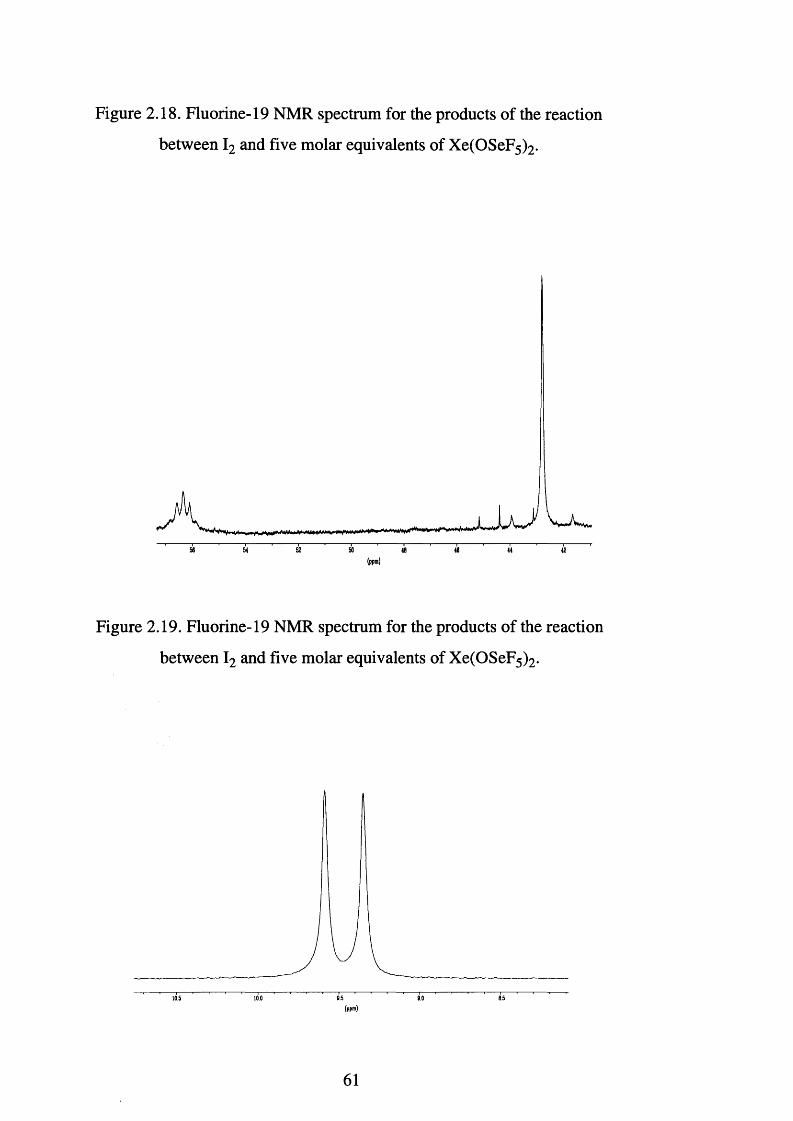
Figure 2.18. Fluorine-19 NMR spectrum for the products of the reaction
between I2 and five molar equivalents of Xe(OSeF5)2.
(ppm)
Figure 2.19. Fluorine-19 NMR spectrum for the products of the reaction
between I2 and five molar equivalents of Xe(OSeF5)2.
(ppm)
61
Although the 19F NMR spectrum is complicated by the large number of
peaks, two AX 4 patterns are visible in the seflate region. If I(OSeF5 ) 5 had been
formed, then two seflate environments would be anticipated due to four
equatorial and one axial seflate groups. No coupling between the fluorine atoms
of the equatorial and axial seflate groups would be expected, as this would
involve coupling through six bonds. The two sets of AX 4 patterns should have
an integration ratio of 4:1, and this is precisely what is observed for the
doublets at 566.8 and 559.7 ppm. Therefore, it is assumed that these two signals
are due to the equatorial fluorines of I(OSeF5)5. Furthermore, on the basis of
integration it can be seen that the doublet at 5Fe 59.7 ppm is associated with the
quintet at 5Fa 73.6 ppm, and the doublet at 5Fe 6 6 . 8 ppm is associated with the
quintet at 5Fa 78.3 ppm. This leads to values of Aab (axial seflate) = -13, and
AAb (equatorial seflate) = -11.5; on comparison to the Aab values presented in
Table 2.4 it can be seen that the interaction possesses some covalent nature, as
would be expected an iodine (V).
No 19F NMR chemical shifts have been previously reported for
I(OSeF5)5, so no comparison is possible. However, the 19F NMR data provides
conclusive evidence for the formation of I(OSeF5)5, and therefore extends the
use of xenon bis(seflate) into the area of high valent non-metal seflate species.
Electron impact mass spectrometry did not show the presence of any
seflate containing species. Presumably decomposition had occurred, as
previously described in Section 2.3. However, the spectrum did contain peaks
which were assigned to [IF5]+ m/z 222, [IF4]+ m/z 203, [IF3]+ m/z 184, [IF2]+
m/z 165, [IF]+ m/z 146 and [I2]+ m/z 254. The presence of the IF5 moiety in the
products of reaction were also confirmed by the 19F NMR spectrum (Figures
2.18 and 2.19) which showed the presence of an AX4 pattern, 5Fe 9.5 ppm and
a quintet at 5Fa 57.0 ppm. This is in excellent agreement with the literature data
for IF5.[i8]
62
A subsequent reaction was carried out using iodine and three molar
equivalents of xenon bis(seflate). Iodine was dissolved in dichloromethane and
then decanted on to the xenon bis(seflate) in a 4 mm FEP tube at 25°C. An
immediate reaction commenced. After 10 minutes gas evolution had ceased and
the reaction was presumed to be complete. The FEP tube was sealed and a 19F
NMR spectrum was recorded. Unreacted iodine was present in the solution, as
evidenced by its purple colour.
Three sets of AX4 patterns with accompanying 77Se satellites were
observed, while, at lower frequency, a singlet with satellites and a doublet were
observed (Table 2.13 and Figure 2.20). Two of the AX4 patterns showed the
same basic features as those for the I2 and five molar equivalents of
Xe(OSeF5)2, namely I(OSeF5 ) 5 (Figure 2.17). However, the third AX4 pattern,
was indicative of another seflate environment. The signals at 5Fa 83.3 ppm and
5Fe 70.0 ppm are not due to the presence of any I(OSeF5 )J23,26 ̂ which at 5Fe
92.0 ppm would be clearly visible.
The 19F NMR data reported^23,26] for I(OSeF5 ) 3 was obtained from a
neat sample. It is not unreasonable to assume that solvent effects will alter the
observed chemical shifts, as demonstrated for Ti(OTeF5 ) 4 (Table 2.5). It is
concluded here that the signals at 8 Fa 83.3 ppm and 5Fe 70 ppm, Aab = -13.8,
arise from the presence of I(OSeF5)3. This is supported by the observation that
on addition of more Xe(OSeF5 ) 2 this signal disappeared and only resonances
assignable to I(OSeF5 ) 5 were observed. The presence of iodine in the reaction
mixture, coupled with the fact that no Xe(OSeF5 ) 2 was observed, would also
suggest that a mixture of products was present.
63
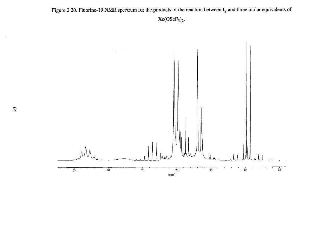
Figure 2.20. Fluorine-19 NMR spectrum for the products of the reaction between I2 and three molar equivalents of
Xe(OSeF5)2.
(ppm)

Table 2.13. Fluorine-19 NMR spectral data for the products of the reaction
between Iodine and three molar equivalents of Xenon bis(seflate).
6 ppm 2J (FaFe)
Hz
lJ( SeFe)
Hz
9.5 (d) 90 -
42.2 (s) - 8 6 8
59.6 (d) 226 1383
66.7 (d)b 2 1 0 -
70.0 (d) 229 1343
73.5 (q)b 2 2 0 -
77.7 (q)a - -
83.3 (q) 227 -
1 L 1 ~~a The quintet was broad and no coupling could be resolved. D J (SeFe) could
not be accurately measured.
In both reactions singlet resonances were observed at either -642.8 ppm,
/(Se-F) = 862 Hz or 642.2 ppm, / ( Se-F) = 867 Hz, and these were presumably
due to the same species. An inspection of the literature indicates that it is not a
selenium (VI) oxide fluoride or fluoride, cf. SeOF4,[3̂ Se2 0 2 F8,[77] S e0 2 F2[78̂
and SeF6 [ 7 9 1 all of which possess Se-F coupling constants in the region of
1500-1300 Hz. The 19F NMR spectrum of neat SeOF2 p ro d u c e s^ a single
resonance at 633.5 ppm, /(Se-F) = 837 Hz. Considering how solvent effects can
considerably alter the observed chemical shifts {cf. Table 2.5), and the
similarity in the magnitude of the coupling constants, it appears the reaction
between iodine and xenon bis(seflate) generates SeOF2 as a decomposition
product.
65
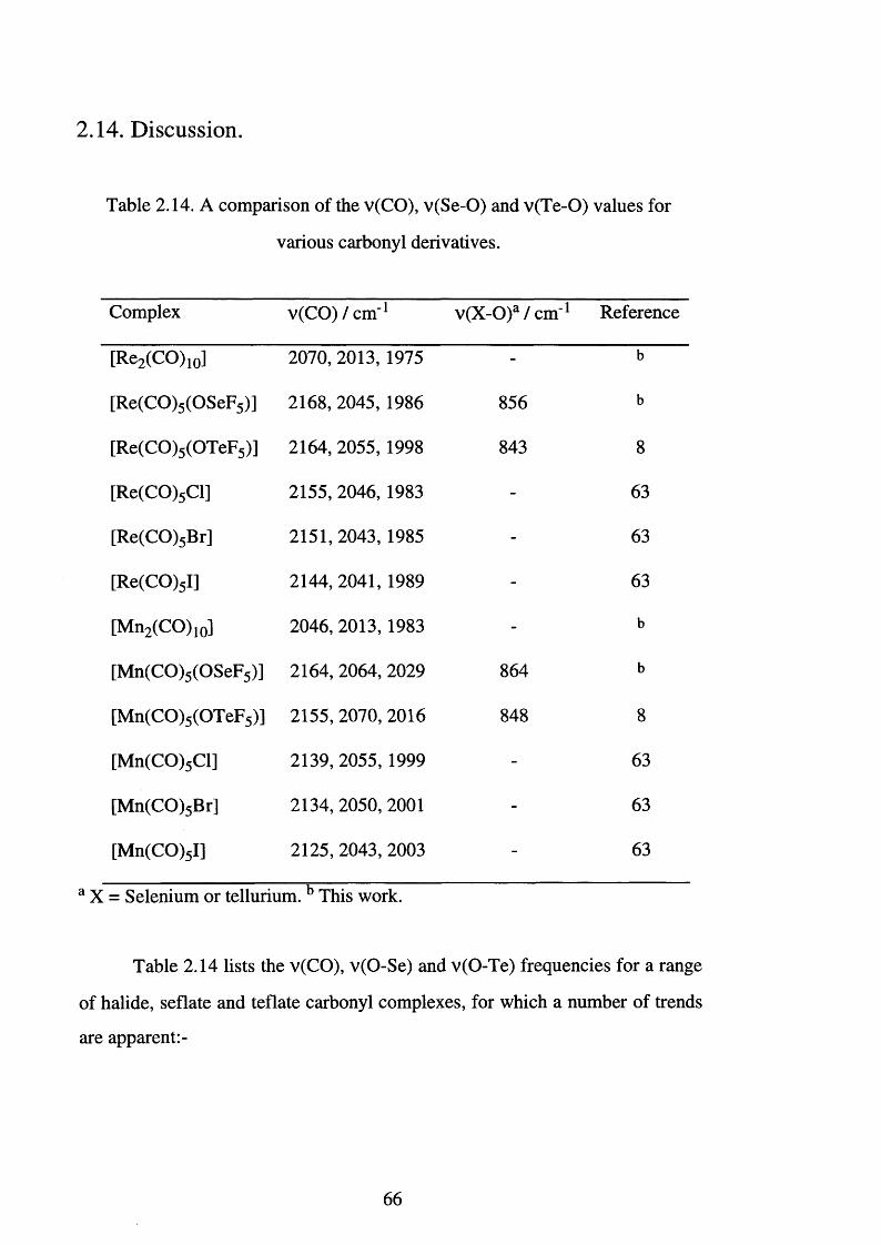
2.14. Discussion.
Table 2.14. A comparison of the v(CO), v(Se-O) and v(Te-O) values for
various carbonyl derivatives.
Complex v(CO) / cm ' 1 v(X -0)a /c m _1 Reference
[Re2 (CO)10] 2070, 2013, 1975 - b
[Re(CO)5 (OSeF5)] 2168, 2045, 1986 856 b
[Re(CO)5 (OTeF5)] 2164, 2055, 1998 843 8
[Re(CO)5 Cl] 2155, 2046, 1983 - 63
[Re(CO)5 Br] 2151,2043, 1985 - 63
[Re(CO)5 I] 2144, 2041, 1989 - 63
[Mn2 (CO)10] 2046, 2013, 1983 - b
[Mn(CO)5 (OSeF5)] 2164, 2064, 2029 864 b
[Mn(CO)5 (OTeF5)] 2155,2070, 2016 848 8
[Mn(CO)5 Cl] 2139, 2055, 1999 - 63
[Mn(CO)5 Br] 2134, 2050, 2001 - 63
[Mn(CO)5 I] 2125, 2043, 2003 - 63
a X = Selenium or tellurium. b This work.
Table 2.14 lists the v(CO), v(O-Se) and v(O-Te) frequencies for a range
of halide, seflate and teflate carbonyl complexes, for which a number of trends
are apparent:-
66
i) On going from Re (0) to Re (I) a shift towards higher frequency is observed
for v(CO). This is the direct result of the increase in the oxidation state which
leads to a decrease in the electron density available for % back bonding.
ii) The v(CO) data for Re(CO)5X and Mn(CO)5X (X = seflate or teflate) are
similar, suggesting that the ionicity of the seflate derivatives is virtually the
same as that for the teflate derivatives.
iii) The carbonyl stretching frequencies for the seflate and teflate compounds
are higher than those for the respective halide analogues. This reflects the high
electronegativities of the seflate and teflate ligands, which, as highlighted in
Section 2.4, are very similar to that of fluorine.
iv) Due to the mass difference between Se and Te, v(Se-O) is greater than
v(Te-O).
It has been demonstrated that xenon bis(seflate) will oxidise zero valent
transition metal carbonyl compounds to produce low valent transition metal
carbonyl seflate species. Table 2.15 highlights the similarities in nature of
seflate and teflate ligands. Although the reaction between xenon bis(teflate) and
[Ru(CO)3 (PPh3 )2 ] may produce [Ru(CO)2 (PPh3 )2 (OTeF5)2], the spectroscopic
evidence is not conclusive. The reaction between xenon bis(seflate) and
[Ru(CO)3 (PPh3 )2] produced a seflate containing species, however, several
species were generated and identification of the products was difficult. The
only product identified was [RuF2 (CO)2 (PPh3 )2 ], and this was presumably a
decomposition product. Although we have shown that the seflate ligand is
compatible with low valent metal carbonyl species, further work is needed to
determine whether the seflate group and phosphine donor ligands are
compatible.
67
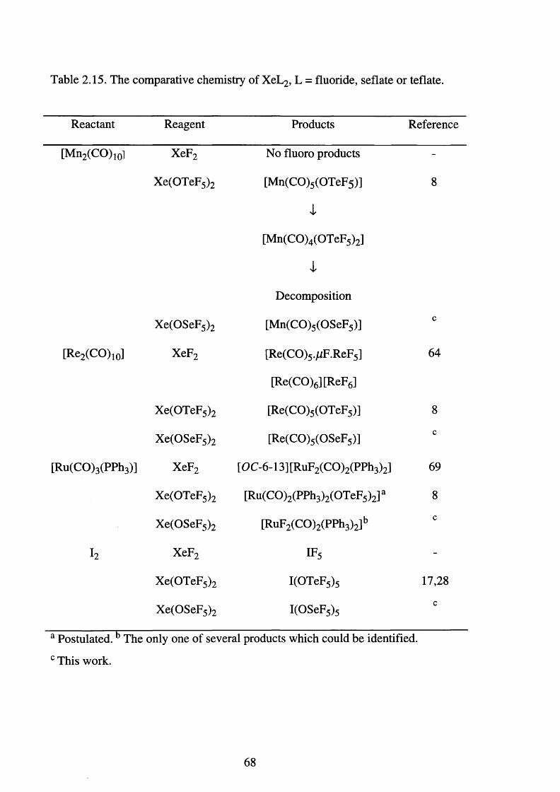
Table 2.15. The comparative chemistry of XeL2, L = fluoride, seflate or teflate.
Reactant Reagent Products Reference
[Mn2 (CO)io] XeF2 No fluoro products -
Xe(OTeF5 ) 2 [Mn(CO)5 (OTeF5)]
4
[Mn(CO)4 (OTeF5)2]
4,
Decomposition
8
Xe(OSeF5 ) 2 [Mn(CO)5 (OSeF5)]c
[Re2 (CO)10] XeF2 [Re(CO)5 .JuF.ReF5]
[Re(CO)6 ][ReF6]
64
Xe(OTeF5 ) 2 [Re(CO)5 (OTeF5)] 8
Xe(OSeF5 ) 2 [Re(CO)5 (OSeF5)] c
[Ru(CO)3 (PPh3)] XeF2 [OC-6-13] [RuF2 (CO)2 (PPh3)2] 69
Xe(OTeF5 ) 2 [Ru(CO)2 (PPh3 )2 (OTeF5)2]a 8
Xe(OSeF5 ) 2 [RuF2 (CO)2 (PPh3)2]bc
h XeF2 i f 5 -
Xe(OTeF5 ) 2 I(OTeF5 ) 5 17,28
Xe(OSeF5 ) 2 I(OSeF5 ) 5c
a Postulated.b The only one of several products which could be identified.
c This work.
68
The teflate group and the fluoride ion are highly electronegative ligands,
and have been closely compared. Indeed, in the area of high valent transition
metal and main group chemistry, the teflate and fluoride ligands are virtually
interchangeable as demonstrated by Table 2.15. However, the Table highlights
one major difference. The isolation of [Mn(CO)5 (OSeF5)] and
[Mn(CO)5 (OTeF5)] clearly distinguishes the seflate and teflate ligands from the
fluoride ion. This difference may be a consequence of the higher
electronegativity of the fluoride ligand which results in an unstable manganese-
carbonyl environment. However, further work is needed to expand the
chemistry of the seflate ligand in order to determine fully the similarities
between the fluoride and seflate/teflate ligands, and the factors which underlie
any differences.
69
References Chapter Two
[1] K. Seppelt, Angew. Chem., Int. Ed. Engl., 1972,15, 630.
[2] A. Engelbrecht and F. Sladky, Angew. Chem., Int. Ed. Engl., 1964, 3,
383.
[3] K. Seppelt, Angew. Chem., Int. Ed. Engl., 1974,13, 91.
[4] K. Seppelt, Angew. Chem., Int. Ed. Engl., 1976,15, 44.
[5] W. Porcham and A. Engelbrecht, Montash. Chem., 1971,102, 333; W.
Porcham and A. Engelbrecht, Z. Phys. Chem. (Leipzig), 1971, 248,
111 .
[6 ] A. Engelbrecht and F. Sladky, Montash. Chem., 1965, 96, 159.
[7] A. Engelbrecht and F. Sladky, Inorg. Nucl. Chem. Lett., 1965,1,15.
[8 ] M. C. Crossman, Ph.D. Thesis, University of Leicester, 1995.
[9] S. H. Strauss, K. D. Abney, K. M. Long and O. P. Anderson, Inorg.
Chem., 1984, 23,1994.
[10] K. D. Abney, K. M. Long, O. P. Anderson and S. H. Strauss, Inorg.
Chem., 1987, 26, 2638.
[11] F. Sladky, H. Kropshofer, O. Leitzke and P. Peringer, J. Inorg. Nucl.
Chem. Supplement, H. H. Hyman Memorial Volume 1976, Pergamon
Press, ed. J. J. Katz and I. Sheft.
[12] H. P. A. Mercier, J. C. P. Sanders and G. J. Schrobilgen, J. Am. Chem.
Soc., 1994,116, 2921.
[13] H. Kropshofer, O. Leitzke and F. Sladky, J. Chem. Soc., Chem.
Commum., 1973, 134; J. F. Sawger, G. J. Schrobilgen, Acta
Crystallogr., Sect. B, 1982, 38, 1561.
[14] H. Kropshofer, O. Leitzke, P. Peringer and F. Sladky, Chem. Ber., 1981,
114, 2644.
[15] H. Kropshofer and F. Sladky, Inorg. Nucl. Chem. Lett., 1972, 8 , 195.
[16] G. W. Fraser and G. D. Meikle, J. Chem. Soc., Dalton Trans., 1975,
1033.
70
[17] G. W. Fraser and J. B. Millar, J. Chem. Soc., Dalton Trans., 1974, 2029.
[18] D. Lentz and K. Seppelt, Angew. Chem., Int. Ed. Engl, 1978,17, 355
and references cited therein.
[19] E. Jacob, D. Lentz, K. Seppelt and A. Simon, Z. Anorg. Allg. Chem.,
1981,472,7.
[20] L. K. Templeton, D. H. Templeton, N. Bartlett and K. Seppelt, Inorg.
Chem., 1976,15, 2718; Inorg. Chem., 1976,15, 2720
[21] K. Seppelt, Chem. Ber., 1972,105, 2431.
[22] K. Seppelt, Angew. Chem., Int. Ed. Engl., 1974, 92, 13.
[23] K. Seppelt, Chem. Ber., 1973,106,1920.
[24] K. Seppelt, Chem. Ber., 1977,110,1470.
[25] A. Clouston, R. D. Peacock and G. W. Fraser, J. Chem. Soc., Chem.
Commum., 1970, 1197.
[26] K. Seppelt, Chem. Ber., 1978,106, 157.
[27] K. Seppelt and D. Nothe, Inorg. Chem., 1973,12, 2727.
[28] D. Lentz and K. Seppelt, Z. Anorg. Allg. Chem., 1980, 460, 5.
[29] P. Huppmann, D. Lentz and K. Seppelt, Z. Anorg. Allg. Chem., 1981,
472, 26.
[30] J. E. Smith and G. H. Cady, Inorg. Chem., 1970, 9, 1442.
[31] K. Seppelt, Chem. Ber., 1972,105, 3131 and references cited therein.
[32] F. Sladky and H. Kropshofer, J. Chem. Soc., Chem. Commum.,
1973, 600.
[33] K. Seppelt, Z. Anorg. Allg. Chem., 1974, 406, 287.
[34] R. Damerius, P. Huppman, D. Lentz and K. Seppelt, J. Chem. Soc.,
Dalton Trans., 1984, 2821.
[35] H. Oberhammer and K. Seppelt, Inorg. Chem., 1978,17, 1435.
[36] H. Oberhammer and K. Seppelt, Angew. Chem., Int. Ed. Engl., 1978,
17, 69 and references cited therein.
[37] K.Seppelt, Angew. Chem., Int. Ed. Engl., 1972,11, 723.
[38] K. Seppelt and H. H. Rupp, Z. Anorg. Allg. Chem., 1974, 409, 338.
71
[39] K. Seppelt, Chem. Ber., 1975,108, 1823.
[40] P. Huppmann, J. Labischinski, D. Lentz, H. Pritzkow and K. Seppelt, Z
Anorg. Allg. Chem., 1982, 487, 7.
[41] T. Birchall, R. D. Myers, H. Waard and G. J. Schrobilgen, Inorg.
Chem., 1982, 21, 1068.
[42] G. J. Schrobilgen, J. H. Holloway, P. Granger and C. Brevard, Inorg.
Chem., 1978,17, 980; G. J. Schrobilgen, NMR and the Periodic Table,
eds. R. Harris and B. Mann, Academic Press, London, 1978, ch. 14.
[43] G. J. Schrobilgen, R. Bums and P. Granger, J. Chem. Soc., Chem.
Commun., 1978, 957.
[44] A. Engelbrecht and P. Peterfly, Angew. Chem., Int. Ed. Engl., 1969, 8 ,
768.
[45] K. O. Christe and H. Oberhammer, Inorg. Chem., 1981, 20, 296.
[46] K. Seppelt, Angew. Chem., Int. Ed. Engl., 1982, 21, 877.
[47] J. A. Pople, W. G. Schneider and H. J. Bernstein, High Resolution
Nuclear Magnetic Resonance, McGraw - Hill Book Co., New York,
1959.
[48] K. Seppelt, Inorg. Synth., 1980, 20, 38.
[49] R. K. Harris and K. J. Packer, J. Chem. Soc., 1961, 4736.
[50] P. Bladen, D. H. Brown, K. D. Crosbie and D. W. A. Sharp,
Spectrochim. Acta, Part A, 1970, 26, 2221.
[51 ] Parameter Adjustment in NMR by Irerative Calculation; NMR Program
Library, Quantum Chemistry Program Exchange.
[52] K. Schroder and F. Sladky, Chem. Ber., 1980,113, 1414.
[53] E. Mayer and F. Sladky, Inorg. Chem., 1975,14, 589.
[54] P. K. Miller, K. D. Abney, A. K. Rappe, O. P. Anderson and S. H.
Strauss, Inorg. Chem., 1988, 27, 2255.
[55] S. H. Strauss, K. D. Adney and O. P. Anderson, Inorg. Chem., 1986, 25,
2806.
[56] P. J. Kellet, Ph.D. Thesis, Colorado State University, 1989.
72
[57] K. D. Abney, K. M. Long, O. P. Anderson and S. H. Strauss, Inorg.
Chem., 1987, 26, 2638.
[58] K. Seppelt, D. Lentz and G. Kloter, Inorg. Synth., 1986, 24, 27.
[59] EXCURV92, SERC Daresbury Laboratory Program, N. Binstead, J. W.
Campbell and S. J. Gurman, 1992.
[60] R. W. Taylor, K. J. Martin and P. Meehan, J. Phys. C, 1987, 20, 4005;
N. Binstead, S. L. Cook, J. Evans, G. N. Greaves and R. J. Price, J.
Amer. Chem. Soc., 1987,109, 3669.
[61] I. C. Bowater, R. D. Brown and F. R. Burden, J. Mol. Spectrosc., 1968,
28, 461.
[62] D. M. Bruce, J. H. Holloway and D. R. Russell, J. Chem. Soc., Dalton
Trans., 1978, 64, 1627.
[63] H. D. Kaesz, R. Bau, D. Hendrickson and J. M. Smith, J. Am. Chem.
Soc., 1967, 89, 2844.
[64] J. H. Holloway, J. B. Senior and A. C. Szary, J. Chem. Soc., Dalton
Trans., 1987, 741.
[65] M. K. Chaudhuri, M. M. Kaschani and D. Winkler, J. Organomet.
Chem., 1976,113, 387.
[6 6 ] E. Horn, M. Snow and P. Zeleny, Aust. J. Chem., 1980, 33, 1659.
[67] R. K. Harris, Nuclear Magnetic Resonance Spectroscopy, Longman, 1st
edn., 1986, 134-137.
[6 8 ] A. J. Hewitt, J. H. Holloway, R. D. Peacock, J. B. Raynor and I. L.
Wilson, J. Chem. Soc., Dalton Trans., 1976, 579 and references cited
therein.
[69] S. A. Brewer, K. S. Coleman, J. Fawcett, J. H. Holloway, E. G. Hope,
D. R. Russell and P. G. Watson, J. Chem. Soc., Dalton Trans., 1995,
1073.
[70] K. S. Coleman, Ph.D. Thesis, University of Leicester, 1996.
[71] H. Krammer, J. Prakt. Chem., 1862, 85, 452.
[72] G. Gore, Proc. R. Soc., 1870,19, 235.
73
[73] H. Moissan, Ann. Chim. Phys., 1891, 24, 244.
[74] H. Moissan, C. R. Seances Acad. Sci.y Paris 1902,135,563.
[75] E. B. R. Prideaux, Trans. Chem. Soc., 1960, 89, 316.
[76] V. Gutmann, Halogen Chemistry, Academic Press, London and New
York, 1967, vol. 1, 133-206.
[77] K. Seppelt, Angew. Chem., Int. Ed. Engl., 1974,13, 92.
[78] K. Seppelt and D. D. Desmarteau, Inorg. Synth., 1980, 20, 36.
[79] E. L. Muetterties and W. D. Philips, J. Am. Chem. Soc., 1959, 81, 1084.
[80] K. Seppelt, D. Lentz and G. Kloter, Inorg. Synth., 1986, 24, 25.
74
CHAPTER THREE
Bromine Oxide Fluoride Chemistry
3.1. Introduction.
The halogen oxide fluorides and their complexes are of fundamental
importance to inorganic chemistry as examples of unusual, discrete, molecular
geometries. When compared with their chlorine and iodine counterparts, the
bromine oxide fluorides have been little investigated, and those compounds
which are known have been poorly characterised.
Our goal was to develop new synthetic routes to novel bromine oxide
fluoride species, and to use low-temperature infrared and EXAFS
spectroscopies as primary characterisation techniques. To put the work into
context an overview of the halogen oxide fluoride chemistry is presented
below. However, hypofluorite compounds will not be included.
3.2. Structures of the Oxide Fluorides.
The shapes of the halogen oxide fluorides can be rationalised using
valence shell electron pair repulsion theoryf1,2̂ (VSEPR). This states that the
geometry of a molecule AXmEn is determined by the repulsion between the
pairs of bonding electrons linking A to the ligands, X, and the non-bonding
electron pairs, E, in the valence shell of the central atom A. Multiple bonds
between A and X are considered to behave like a single pair of electrons, and
thus do not change the overall arrangement of the ligands (although they will
affect the angles between them). The sum of the number of bonding sets of
electrons (m) and the non-bonding pairs of electrons (n) is the criterion which
determines the structure of the molecule. Hence, the geometries are (m+n) = 2
(linear), 3 (triangular), 4 (tetrahedral), 5 (trigonal bipyramidal) and 6
(octahedral). Consideration of the numbers and types of repulsions between the
various electron pairs allows one to predict, which positions will be occupied
by ligands, and which will be taken up by non-bonding electron pairs.
75
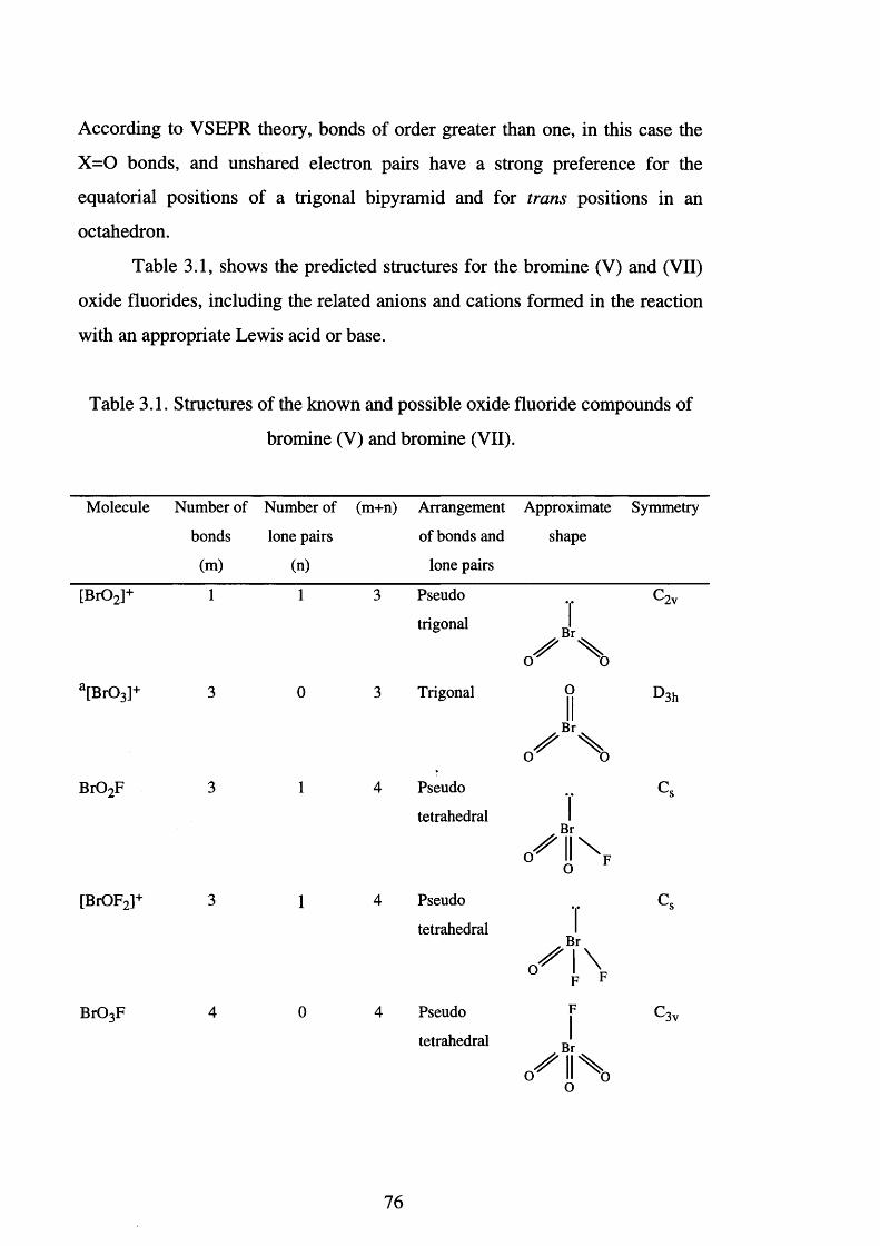
According to VSEPR theory, bonds of order greater than one, in this case the
X = 0 bonds, and unshared electron pairs have a strong preference for the
equatorial positions of a trigonal bipyramid and for trans positions in an
octahedron.
Table 3.1, shows the predicted structures for the bromine (V) and (VII)
oxide fluorides, including the related anions and cations formed in the reaction
with an appropriate Lewis acid or base.
Table 3.1. Structures of the known and possible oxide fluoride compounds of
bromine (V) and bromine (VII).
Molecule Number of Number of (m+n) Arrangement Approximate Symmetry
bonds lone pairs of bonds and shape
(m) (n) lone pairs_____ _ _ _ Pseudo “
trigonal
Br
o^llN
Br
c/'INF F
Br03F 4 0 4 Pseudo F
tetrahedral
O
3ha[Br03]+ 3 0 3 Trigonal jj D
/ Xo o
Br02F 3 1 4 Pseudo Cs
tetrahedral I
O
[BrOF2]+ 3 1 4 Pseudo .. Cs
tetrahedral
'3v
76
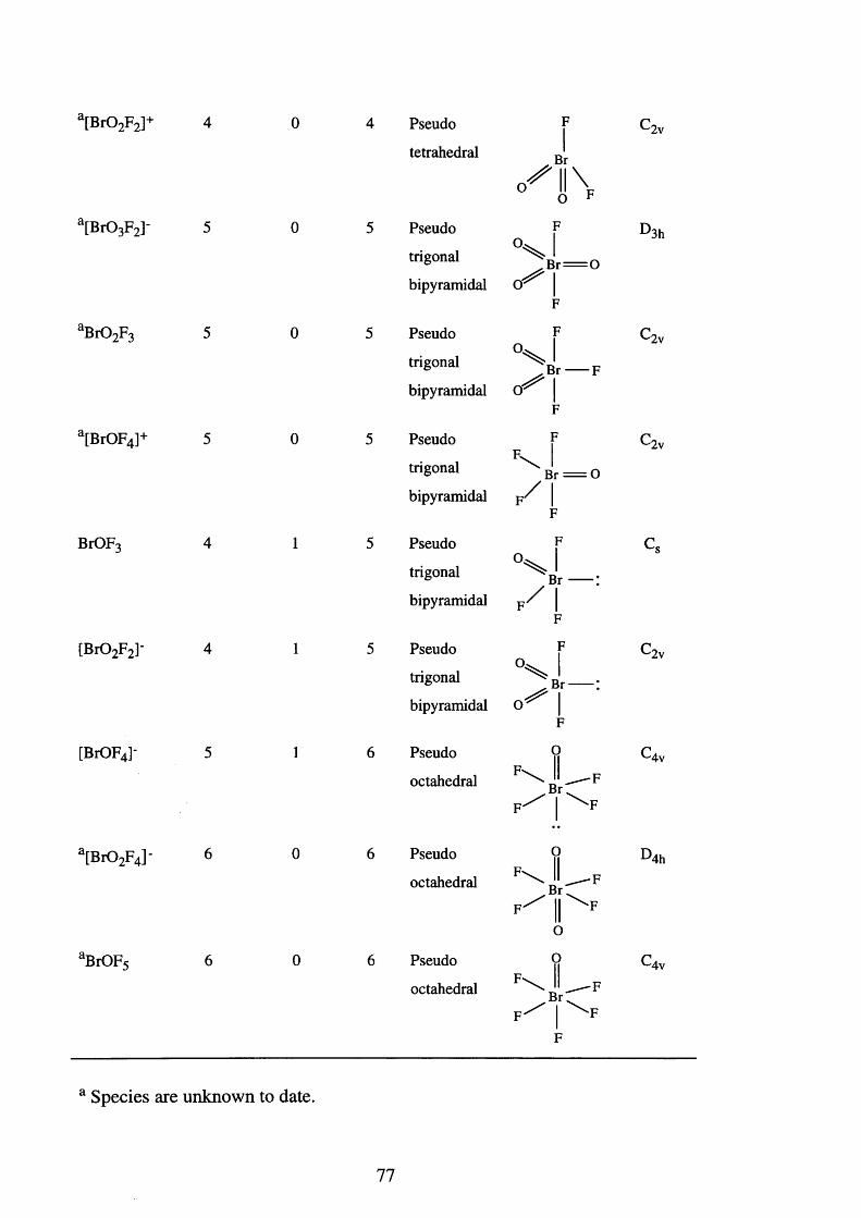
a[Br02F2]+ 4 0 4 Pseudo
tetrahedral
F
Br
o ^ l l \0 F
c2v
a[Br03F2]- 5 0 5 Pseudo
trigonal
bipyramidal
F
V lBr = 0
0^1F
D 3h
aBr02F3 5 0 5 Pseudo
trigonal
bipyramidal
F
v j. B r ----- F
o ^ |F
C2v
a[BrOF4]+ 5 0 5 Pseudo
trigonal
bipyramidal
F
' s L op / i
F
c2v
BrOF3 4 1 5 Pseudo
trigonal
bipyramidal
F
v jB r ----- 1
f/ |F
Cs
[Br02F2]- 4 1 5 Pseudo
trigonal
bipyramidal
F
J. B r ----- :
IF
C2v
[BrOF4]- 5 1 6 Pseudo
octahedral
0F\ II_F
Rr--C4v
l[Br02F4]
aBrOF<
Pseudo
octahedral
Pseudo
octahedral
OII
Br:
OO
D4h
Br:
F
-F'F
-F
‘F
'Aw
Species are unknown to date.
77

3.3. The Halogenyl Fluorides, XO2F.
3.3.1. Chloryl fluoride.
Chloryl fluoride, C102 F, has been prepared by several methods. Early
syntheses used shock-sensitive chlorine oxides such as C120 and C102 J 3,4̂ The
danger involved with the use of these materials can be avoided by the use of
equimolar amounts of C1F3 and Na[C103] which also gives rise to C102 F.[5,6]
Chloryl fluoride, a colourless gas at room temperature, is a powerful
oxidising and fluorinating reagent which is stab le^ up to 300°C. Studies using
microwave spectroscopy have provided information on the molecule's internal
param eters'8,9 ̂ and shown that it has the predicted Cs symmetry.
The reaction of C102F with dried CsF at -80°C affords
Cs[C102 F2],^10,11̂ and analysis by infrared spectroscopy^ produces data
consistent with the anion being a pseudo-trigonal bipyramid of C2v symmetry.
Chloryl fluorides react with the Lewis acids BF3, PF5, AsF5, SbF5 and VF5^ to
form salts comprising of the cation [C102]+ and the anions [BF4]', [PF6]‘,
[AsF6]', [SbF6]' and [VF6]' respectively. The reaction with PtF6 gives a
mixture of [C102 F2]+[ PtF6]‘ and [C102 ]+[PtF6] \ [13,14]
3.3.2. Bromyl fluoride.
Bromyl fluoride, B r0 2 F, has been known since the early 1950's,
although its synthesis has aroused much controversy. In 1957, Schmeisser
reported that the reaction between BrF5 and K [Br03] at -60°C yielded B r0 2F
among its p r o d u c t s H o w e v e r , Bougon reported that K [B r0 2 F2], BrF3 and
0 2 are produced, ̂ whilst Gillespie suggested that the product mixture
consisted of K [B r0 2 F2], K[BrOF4] and B r0 2 F j 17̂ Evidently no clear and
established route exists to bromyl fluoride. This may be a result of the highly
78
reactive character of B r0 2 F, or a reflection of the variety of products that may
be produced in the reaction.
Bromyl fluoride is a colourless solid at low temperatures with a melting
point of -9 °C .^ At room temperature, it slowly decomposes and the liquid
produced is generally yellow owing to the presence of BrF3. The liquid
decomposes violently above 56°C to BrF3, Br2 and 0 2. The Raman spectra of
bromyl fluoride, ̂ 18-2°] as neat compound and as an HF solution, are
consistent with a monomeric, pseudo-pyramidal molecule of Cs symmetry. It
forms adducts with AsF5 and SbF5 J 21,22 ̂ which are, however, of low stability
and decompose near room temperature. The reaction of PtF6 and B r0 2F at
-120°C yields a mixture of [BrOF2 ]+[PtF6]' and [B r0 2 ]+[PtF6] '.[23] The
attempted oxidative fluorination of B r0 2F using KrF2 does not yield bromine
(VII) oxide fluorides, but instead, proceeds via BrOF3, to yield BrF5 as the only
product.
Bromyl fluoride will form adducts with Lewis bases such as KF.
However, a preferable route to K [B r0 2 F2] is the fluorine-oxygen exchange
reaction between K[BrF6] and K [B r03] in CH3 CN.[19] A mixture of K [B r0 2 F2]
and K[BrOF4] is obtained, and separation of the products exploits the solubility
of K[BrOF4] in CH 3 CN, compared with the insolubility of K[BrOF4].
Potassium difluorobromate, K [Br0 2 F2], is a white solid which is stable at room
temperature. Using infrared and Raman spectroscopy, Bougon et al. have
shown[24] that the structure is a pseudo-trigonal bipyramid of C2v symmetry.
3.3.3. Iodyl fluoride.
Iodyl fluoride, I 0 2 F, was first prepared in 1953[251 by the thermal
decomposition of IOF3, which also produces IF5. The reaction is reversible, and
consequently, IOF3 is formed by refluxing I 0 2F with IF5. Iodyl fluoride is also
produced by the fluorination of I2 0 5 in AHF, at 20°CJ3̂ Iodyl fluoride is a
stable colourless solid at room temperature, which slowly evolves HF in moist
79
air.t16̂ Vibrational spectroscopic s tu d ie s ^ were hampered by the complexity
of the spectra, which is indicative of extensive couplings between the different
vibrational modes. This, together with low volatility at high temperatures
suggests that I 0 2F is a polymeric species.
Iodyl fluoride reacts with Lewis acids to form salts such as
[I0 2 ]+[AsF6]" On the other hand, reaction of I 0 2F with Lewis bases affords
complexes involving the anion [I0 2 F2]'. Thus, KF and I 0 2F react in AHF to
yield K [I0 2 F2] and vibrational spectroscopic studies indicate that it is
isostructural with [C102 F2]' and [B r0 2 F2]'.
3.4. Halogen Oxide Trifluorides, XOF3 .
3.4.1. Chlorine oxide trifluoride.
Chlorine oxide trifluoride, C10F3, was first synthesised in 1 9 6 5 ^ by
the fluorination of C12 0 , a route limited by the explosive nature of C12 0 . Later,
Bougon et a l prepared CIOF3 by the UV irradiation of a mixture of C1F3 and
OF2 J 28] A large scale preparation^29̂ involves the fluorination of chlorine
nitrate, C 10N 02, at -35°C, which affords a mixture of C10F3 and F N 02. These
are separated by virtue of a large difference in their vapour pressures.
Chlorine oxide trifluoride is a colourless compound with a melting point
of -43°C and a boiling point of 28°C. Gas phase electron diffraction showed the
molecular structure to be a distorted pseudo-trigonal bipyramid,[30̂ with a
doubly bonded oxygen and a lone pair lying in the equatorial plane. Chlorine
oxide trifluoride possesses a stability intermediate between that of C1F3 and
CIF5 , and reacts with glass, quartz and most metals causing both fluorination
and oxygenationP 1̂ Its reaction with organic substances, even at low
temperatures can be explosive. As a powerful oxidant, it has proved to be a
useful supporter of combustion for rocket fuels such as N2 H4.
80
Chlorine oxide trifluoride forms stable 1:1 adducts with a variety of
Lewis acids,t27,32J e.g. BiF5, SbF5, AsF5, TaF5, NbF5, VF5, PF5 and BF3. The
vibrational spectra observed for the [C10F2]+ salts[33] showed the presence of
six fundamental vibrations, which is consistent with them being pseudo-
tetrahedral molecules of Cs symmetry. Chlorine oxide trifluoride forms stable
adducts with strong Lewis bases^32,34 ̂ such as CsF, RbF and KF; but no
reaction was observed with the weaker base NOF. Vibrational spectroscopic
data was used to infer the molecular structure of [C10F4 ] 'J 32̂ however, it
appears that splitting of the degenerate modes led to an inconclusive
assignment. Further reactions include attempts to isolate a [C10F4]+ salt,
utilising the reactions of CIOF3 with SbF5 -F2 or PtF6 J 14,34̂ These failed but the
latter reaction produced [C10F2 ]+[PtF6]".
3.4.2. Bromine oxide trifluoride.
Bromine oxide trifluoride was first prepared^35] by the reaction of
K[BrOF4] and [0 2 ]+[AsF6]" in a solution of BrF5. It can also be made using the
reaction of K[BrOF4] and the weak Lewis acid HF.[17̂ The HF is removed at
low temperature to leave K[HF2] and BrOF3. The BrOF3 cannot simply be
distilled from the BrOF3 -K[HF2] mixture since the reaction is reversible.
Instead, BrF5, into which the BrOF3 dissolves, is distilled on to the mixture.
The solution can then be decanted off to leave the solid behind. In 1987, Wilson
and Christe developed a new, high yield, one-step synthesis of BrOF3 which
involves the reaction of L i[N 03] and an excess of BrF5 J 36^
Bromine oxide trifluoride is a colourless liquid^3 7 1 or solid, with a
melting point range of -5 to 0°C. At room temperature it slowly decomposes to
produce BrF 3 and 0 2. Vibrational spectroscopic data has provided conclusive
evidence that its structure is pseudo-trigonal bipyramidal,[19,38] analogous to
that of C10F3.
81
Bromine oxide trifluoride possesses a similar amphoteric nature to that
of CIOF3 . The reaction between BrOF3 and the Lewis acids BF3, AsF5 and
SbF5 affords1 3 9 1 the adducts [BrOF2 ]+[BF4]-, [BrOF2 ]+[AsF6]’ and
[BrOF2 ]+[SbF6] ' respectively. The stability of the complex formed increases
considerably with the increasing strength of the Lewis acid employed. The
adduct [BrOF2 ]+[SbF6]" can also be prepared from the reaction between
I 0 2 F3 *SbF5 and BrF5. The vibrational spectroscopic data from these
complexes^23’37,39,40] are consistent with their containing a cation of pseudo-
pyramidal geometry (Cs symmetry) and the assignments made are in good
agreement with those for the isostructural species SeOF2, SOF2 and [C10F2]+.
Salts of the anion [BrOF4]" are easily synthesised using the method
described by Wilson and ChristeJ36̂ The reaction between BrF5 and the alkali
metal nitrates M [N 03], M = Na, K, Rb or Cs, yields the corresponding anionic
salts. From Na+ —» Cs+, smaller excesses of BrF5 and shorter reaction times are
required. The salts are stable white solids at room temperature, and the
vibrational data suggest that the anion possesses C4v symmetry. However, as
with [C10F4]‘, the assignments were made difficult due to splittings of the
degenerate modes.
3.4.3. Iodine oxide trifluoride.
Iodine oxide trifluoride was first claimed to have been synthesised by
Ruff and Braida in 1934. Later, in 1953, this claim was c o n firm ed ^ when
IOF3 was prepared by refluxing a saturated solution of I2 0 5 in IF5. On cooling,
colourless needles of IOF3 are formed. Iodine oxide trifluoride is stable up to
110°C at which temperature it decom poses^ to IF5 and I 0 2F and, as explained
earlier, this is reversible (see Section 3.3.3). Iodine oxide trifluoride has been
characterised using X-ray crystallography.^ The molecular structure is a
pseudo-trigonal bipyramid with axial fluorines and a lone pair, a doubly bonded
82
oxygen and a fluorine lying in the equatorial plane. The compound is
isostructural with CIOF3 .
The anion [IOF4]‘ is accessible from the indirect reaction of KF and
I2 0 5, in a 5:1 molar ratio, with a large excess of IF5/ 42! The mixture is refluxed
for one hour and the white solid isolated is stable up to 200°C. Quenching with
water produces HF and K [I03]. X-ray crystallography^42! has shown that
[IOF4 ] ' is a square based pyramid with the four fluorine atoms in the equatorial
plane; the vibrational spectroscopic data is in accord with the predictions that
the molecule would have C4v symmetry.
3.5. Perhalogenyl Fluorides, XO3F.
3.5.1. Perchloryl fluoride.
Perchloryl fluoride, C103 F, was first synthesised in the early 1950's and
has been extensively investigated since. Perchloryl fluoride is readily prepared
by several different rou tes/19! including the fluorination of K[C103] using F2,
in the super-acid medium H S 0 3 F-SbF5. The electrolysis of a saturated solution
of NaC104 in AHF also yields CIO3 F.
Perchloryl fluoride is a stable colourless gas with a melting point of -47
°C. The physical properties are well documented/19! Its inertness relative to the
other halogen oxide fluorides is a consequence of its energetically favourable
pseudo-tetrahedral configuration. Perchloryl fluoride hydrolyses slowly in
water and is thermally stable up to 400°C. As a consequence of the low polarity
of CIO3 F, it is soluble in a wide range of non-polar solvents/43! and at elevated
temperatures it is a powerful oxidising agent. Gas-phase electron diffraction
studies confirm that it has a pseudo-tetrahedral geometry of C3v symmetry/44!
Applications include its selective fluorinating properties in organic
chemistry/45 ̂ e.g. the replacement of the hydrogen atoms of a CH 2 group by
fluorine. It is also possible to introduce chlorate groups, [CIO3 ], into organic
83
molecules, e.g. the reaction of C6 H5Li and C103F produces C6 H5 C103 J46 ̂
Perchloryl fluoride has also been extensively used, alone or mixed, with other
halogen fluorides as an oxidant for rocket fuels . [ 2 7 1 The UV photolysis of
CIO3 F and CIF3 , CIF5 , OF2 or F2 produces C10F3 J47 ̂ Perchloryl fluoride
behaves as a mild fluorinating agent and converts UF4 to UF6 via an unknown
uranium oxide fluoride,f48̂ but it is inert towards both Lewis acids and bases.
3.5.2. Perbromyl fluoride.
Perbromyl fluoride, B r0 3 F, is prepared by the action of a powerful
fluorinating agent such as SbF5, AsF5, [BrF4 ]+[AsF6] ' or BrF5 on [KBr04] in
anhydrous HFJ49,50 ̂Perbromyl fluoride is a colourless gas with a melting point
of -110 °C. Electron diffraction studies confirm the structure is pseudo-
tetrahedral and vibrational studies are in agreement with the molecule
having C3v symmetry.
The chemical behaviour of B r0 3F is similar to that of CIO3 F. However,
the difficulty involved in making B r0 3 F, and its lower stability, means its
chemistry is less diverse. No adducts of B r0 3F with Lewis acids or bases have
been reported to date.
3.5.3. Periodyl fluoride.
Periodyl fluoride, I 0 3 F, can be prepared by passing fluorine through a
solution of H I0 4 in HF, or by the reaction of K [I04] with H S 0 3 f J 48,52,53 ̂ It is
a white solid which is stable up to 100°C. Vibrational analysis has been
attempted, however, polymerisation appears to occur and this has prevented a
satisfactory assignment. Periodyl fluoride possesses some fluoride ion donor
properties and a solution of the compound in HF reacts with AsF5 or BF3 to
give compounds containing the cation [I0 3 ]+.
84
3.6. Halogen Dioxide Trifluoride, XO2F3 .
3.6.1. Chlorine dioxide trifluoride.
Chlorine dioxide trifluoride is prepared by a multi-step synthesis.1[54̂ The
oxidation of C102F using PtF6 produces [C102 F2 ]+[PtF6]" and [C102 ]+[PtF6] \
The reaction of these cations with F N 0 2 or FNO, at -78°C, produces C102 F3
and C102F respectively. The C102 F3 is then separated from the C102F by
fractional condensation. Any remaining C102F can be removed by the addition
of BF3 to the mixture, and this produces the adducts [C102 F2 ]+[BF4]' and
[C102 ]+[BF4]". The species [C102 ]+[BF4]‘ is unstable above 20°C, and can be
removed as it is the only volatile product. The final step involves the reaction of
[C102 F2 +][BF4]" with F N 0 2 which liberates the volatile C102 F3. Chlorine
dioxide trifluoride is a stable g a s ^ with a melting point of -81°C and a boiling
point of -22°C. Vibrational studies combined with 19F NMR spectroscopic
data^54! are consistent with C102 F 3 having the structure of a pseudo-trigonal
bipyramid of C2v symmetry; this corresponds to two fluorines occupying the
axial positions, as would be predicted using VSEPR theory.
Chlorine dioxide trifluoride is a strong oxidative fluorinator which reacts
explosively with organic materials and fluorinates metal surfaces, producing
c i o 2 f .
The synthesis of [C102 F2]+ has already been highlighted above, and salts
with the corresponding counter ions [PtF6] \ [BF4]' and [AsF6]" are solids
which are stable at 25°CJ55 ̂ They all react violently with water and organic
materials, and dissolve in AHF without decomposition. Characterisation of the
adducts by 19F NMR and vibrational spectroscopy give rise to the conclusion
that the structure of the cation is pseudo-tetrahedral with C2v symmetry.
Validation of the assignment is possible because of the similarity of the
spectrum of [C102 F2]+ to the spectrum of the isostructural SQ2 F2.
85
3.6.2. Bromine dioxide trifluoride.
Although there have been numerous attempts to synthesise bromine
dioxide trifluoride it has never been isolated. Unsuccessful routes include: the
fluorination of B r0 2F using KrF2,[19J the fluorination of B r0 3F by
[KrF]+[AsF6] '[37l and the hydrolysis of BrF5 in HF at low temperatures.[56]
Mass spectrometry of the hydrolysis products of BrF5 and BrF3 has suggested
the presence of [B r0 2 F2]+. However, this seems unlikely considering the high
energy barrier associated with the conversion of bromine (V) to bromine (VII).
3.6.3. Iodine dioxide trifluoride.
Iodine dioxide trifluoride was first obtained by Engelbrecht^57 ̂ in 1969.
A twenty-fold excess of H S 03F was allowed to react with [Ba3 H4 (I0 6)2] . The
mixture was then distilled under reduced pressure, and the fraction obtained
contained HOIOF4 and H S 03F in a 2:1 molar ratio. The addition of oleum
converted the HOIOF4 to I 0 2 F3, which was then separated from the mixture by
sublimation, under reduced pressure, on to a cold finger.
Iodine dioxide trifluoride is a yellow crystalline s o l id ^ with a vapour
pressure of 5 torr at 25°C. It attacks glass and quartz slowly at room
temperature and is photosensitive, producing IOF3 and 0 2. It is a strong
oxidising agent, reacting explosively with organic molecules at room
temperature. Iodine dioxide trifluoride exists in two isomeric form s,*^ the
ratio of which is solvent and temperature dependent. This molecule does not
obey VSEPR theory, which states that the most electronegative elements
occupy the axial positions of a trigonal bipyramid. The C2v isomer has both the
axial positions occupied by fluorine atoms, whereas the Cs isomer has an
oxygen atom in one of these positions (Figure 3.1).
86
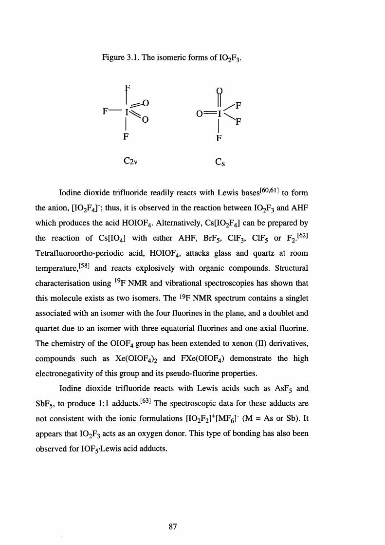
Figure 3.1. The isomeric forms of I 0 2F3.
H
o
F F
C2v Cs
Iodine dioxide trifluoride readily reacts with Lewis bases^60,6^ to form
the anion, [I0 2 F4]'; thus, it is observed in the reaction between I 0 2 F3 and AHF
which produces the acid HOIOF4. Alternatively, C s[I0 2 F4] can be prepared by
the reaction of C s[I04] with either AHF, BrF5, C1F3, C1F5 or F2 J62 ̂
Tetrafluoroortho-periodic acid, HOIOF4, attacks glass and quartz at room
t e m p e r a t u r e , a n d reacts explosively with organic compounds. Structural
characterisation using 19F NMR and vibrational spectroscopies has shown that
this molecule exists as two isomers. The 19F NMR spectrum contains a singlet
associated with an isomer with the four fluorines in the plane, and a doublet and
quartet due to an isomer with three equatorial fluorines and one axial fluorine.
The chemistry of the OIOF4 group has been extended to xenon (II) derivatives,
compounds such as Xe(OIOF4 ) 2 and FXe(OIOF4) demonstrate the high
electronegativity of this group and its pseudo-fluorine properties.
Iodine dioxide trifluoride reacts with Lewis acids such as AsF5 and
SbF5, to produce 1:1 adductsJ63 ̂ The spectroscopic data for these adducts are
not consistent with the ionic formulations [I0 2 F2 ]+[MF6]" (M = As or Sb). It
appears that I 0 2 F3 acts as an oxygen donor. This type of bonding has also been
observed for IOF5 Lewis acid adducts.
87
3.7. Halogen Oxide Pentafluorides, XOF5 .
3.7.1. Chlorine oxide pentafluoride.
Chlorine oxide pentafluoride, CIOF5 , has been reported as a product
from the photochemical reaction of C1F5 and OF2 in a nickel vessel
However, no spectroscopic data has been published.
3.7.2 Bromine oxide pentafluoride
Four documented attempts have been made to synthesise BrOF5. These
are: i) the UV irradiation of BrF5 and excess of OF2 between -60 and -40°C j14̂
ii) the heating of a mixture of BrF5 and 0 2 at 4300 psi to 207°C,[37] iii) the
hydrolysis of [BrF6 ]+[AsF6]+ in HF^37̂ and iv) the reaction of BrOF3 and
KrF2 J 19̂ However, BrOF5 still remains unknown.
3.7.3. Iodine oxide pentafluoride.
Iodine oxide pentafluoride, IOF5, is formed by the reaction of IF7 and
water, silica or I2 0 5 J65"68 ̂ Another route, proposed by Christe and SchackJ69 ̂
employs the use of the ligand transfer reagent POF3, which reacts with IF7 to
produce IOF5 and PF5. Iodine oxide pentafluoride is a colourless liquid at room
temperature with a melting point of 4°C. The molecule has been characterised
using electron diffraction^70 ̂ and the structure confirmed as an octahedron of
C4v symmetry. Fluorine-19 NMR and vibrational spectroscopic d a t a ^ are in
agreement with this result.
Iodine oxide pentafluoride reacts with AsF5 and SbF5 to form 1:1
adducts. Vibrational and NMR spectroscopic d a t a ^ suggested that the species
formed are not the expected donor-acceptor complexes, but are adducts in
88
which the Lewis acid is bonded to the IOF5 via the oxygen atom. Iodine oxide
pentafluoride readily reacts with the Lewis base [NMe4]+F to form the adduct
[IOF6 ]'[NM e4 ]+J72,73 ̂ This colourless crystalline solid has a melting point of
172°C, and the structure of the anion, determined by X-ray crystallography^73 ̂
is a pseudo-pentagonal bipyramid of C5v symmetry.
3.8. Halogen Oxide Fluoride, XOF.
3.8.1. Chlorosyl fluoride.
Chlorosyl fluoride, ClOF, is the only known halogen (III) oxide fluoride
and was first reported in 1930 by Ruff and KingJ74 ̂ The solid melts to a red
liquid at -70°C and is unstable in the gaseous state. Infrared spectroscopy has
shown[75] that this compound is the primary hydrolysis product of C1F3. In
1974 Andrews et al. demonstrated^76 ̂ that ClOF was formed during the
photolysis of 0 3 and C1F in a krypton matrix at -258°C. Vibrational
spectroscopic data and normal coordinate analysis provided the means to
determine the bond lengths, and a bond angle, F-Cl-O, of 120°.
3.9. Summary.
The oxide fluorides of chlorine and iodine have been extensively
studied, and most of the neutral complexes have been shown to exhibit
amphoteric behaviour. Thus, an oxide fluoride, XOnFm, reacts with a Lewis
acid to produce the cation [XOnFm_1]+, whilst, with a fluoride ion donor, it
produces the anion [XOnFm+1]".
Several of the structures proposed on the basis of VSEPR theory have
been confirmed by the structural characterisation of one of the halogen oxide
fluoride species. The only deviations appear to be in the case of iodine, where
89
for example [I0 2 F3] is dimeric and, [I0 3 F] and [I0 2 F] are polymeric. This is
associated with the transition from the fourth to the fifth row of elements: the
inclusion of the Lanthanide series causing an increase in the co-ordination
number.
3.10. The Unusual Nature of Bromine (VII).
By analogy with chlorine and iodine, bromine (VII) oxide fluoride
complexes are expected to exist, and the ease of accessing this valence state
should be intermediate between that of chlorine and iodine. However, out of a
possible eight bromine (VII) oxide fluorides only one is known.
Perchlorate (VII) salts were first prepared via the oxidation of chlorates
using sulphuric acid in 1816J771 Trisodium paraperiodate, Na3 H2 [I06], was
first prepared by the oxidation of sodium iodate using chlorine in 1833J78 ̂
However, perbromate was not successfully prepared until 1968,^79 ̂ and then by
the exotic means of a hot atom process namely, the (3 decay of radioactive
selenium, (8 3 Se) (Eqn. 3.1). The precipitation of the perbromate anion as the
rubidium salt led to the first isolation of a perbromate salt.
[8 3 Se0 4]2" -> [83Br04r + P" Eqn. 3.1.
The first macro scale preparation of perbromates was performed using
the electrolytic oxidation of a neutral solution of L i[Br03] . The yield of this
reaction was rather poor at 1%. A more successful method involves the use of
aqueous XeF2 which produces [Br04]" in a 10% yield (Eqn. 3.2).
[BrO3] ' + H20 + XeF2 -» Xe + [Br04]’ + 2 HF Eqn. 3.2.
90
The most practical synthesis involves the oxidation of [B r03] ' using
elemental fluorine in aqueous sodium hydroxide (Eqn. 3.3). This preparation^80̂
involves a hazardous fluorination stage and a rather lengthy purification. The
yields obtained are around 2 0 %.
[B r03]" + F2 + 2 OH" -> [Br04]" + 2 P + H20 Eqn. 3.3.
The isolation of potassium perbromate involves the neutralisation of
perbromic acid with potassium hydroxide. Perbromic acid is a strong
monobasic acid, which is stable up to 6 M (55% H B r04), even at 100°C.
Concentrated solutions develop a yellow tinge due to the decomposition of
trace amounts of hypobromous acid, HOBr. Above 6 M, perbromic acid tends to
be erratically unstable although the decomposition is not explosive. The
concentration in vacuo, at room temperature, produces an azeotrope which
consists of about 80% perbromic acid (ca. 12 M). However, it usually
decomposes during or shortly after preparation. The molecular distillation of
this azeotrope is possible if heat is applied rapidly in a high vacuum.
The bromate-perbromate electrode potential is 1.74 volts in acid
solution,^8^ making perbromic acid a potent oxidant (cfi perchlorate E° = 1.23
V and periodate E° = 1.64 V). Dilute solutions react sluggishly with Br" and I"
at room temperature, whilst chloride ions are unaffected. However, 6 M
perbromic acid attacks stainless steel and, at 100°C, it oxidises Cl" to Cl2, Cr
(III) to Cr (VI), Mn (II) to Mn (IV) and Ce (III) to Ce (IV).
Potassium perbromate is stable up to 275°C,^80̂ at which temperature it
decomposes to potassium bromate and oxygen, however, the impure compound
may partially decompose at lower temperatures.
The numerous unsuccessful attempts to prepare the perbromate ion[82̂
and its long-time status as a "non existent" species is surprising, particularly in
view of its considerable stability. The oxidation potential of 1.74 V suggests
that the use of ozone (E° = 2.07 V) to oxidise bromate to perbromate should be
91
s u c c e s s f u l H o w e v e r , its rather sluggish oxidising nature suggests that a
large activation energy exists between Br (VII) and Br (V). Hence, the overall
energy required for the formation of [Br04] ' from [B r03]' is the sum of the free
energy change for the reaction, plus the activation energy. Thus, to overcome
the energy barrier only the strongest oxidising agents are successful.
To date only two other bromine (VII) species have been isolated. One is
perbromyl fluoride, B r0 3 F, the preparation of which involves the use of the
super-acid media HF-SbF5 J 83̂ The other, [BrF6]+, can be prepared^84! by the
reaction between [KrF]+-[Kr2 F3]+ and BrF5. Both B r0 3F and [BrF6]+ are quite
stable at room temperature although B r0 3F is considerably more reactive than
its chlorine analogue. The salts of [BrF6]+ are extremely powerful oxidising
agents^84] and will oxidise 0 2 to [0 2]+ and Xe to [XeF]+.
Table 3.2. Standard electrode potentials (in acid solution) between
highest oxidation states of non metals.
Periodic Group
15 16 17
Species Involved
h 3 x o 3 h 3 x o 4 h 3 x o 3- h 3 x o 4- xo3- xo4-p -0.28 S 0 . 1 0 C1 1.23
As 0.57 Se 1.09 Br 1.74
Sb 0.72 Te 0.90 I 1.64
It can be seen (Table 3.2) that the perbromate anion is a more powerful
oxidant than perchlorate or periodate. This situation is not that different to what
is found for the elements of Groups 15 and 16 (Table 3.2). As is highlighted the
compounds become less potent oxidants to the left of the periodic table, and
this reflects the decreased nuclear charge of the species. However, it is
92
apparent, that a large increase in the oxidising power, of the highest oxidation
state oxo acids, occurs on going from the last short period (P, S and Cl) to the
first long period (As, Se, Br); whereas, only small changes in oxidising power
occur between the next periods
Prior to the isolation of perbromate salts several explanations were put
forward to account for their anomalous absence. Amongst them were inner
sphere electron repulsions^85! a high s to p promotion energy^86! and the
presence of a node in the bromine 4d orbitalJ87̂ the region most favourable for
bonding. However, no satisfactory explanation exists for the experimental
difficulties that were encountered in the synthesis of high oxidation state
bromine compounds.
3.11. Area of Study.
There is a scarcity of bromine oxide fluoride compounds compared to
their respective chlorine and iodine analogues. However, following work by
Gillespie and Spekkens,^21 ̂ all of the bromine (V) oxide fluorides have been
prepared, including the corresponding anions and cations. The structures
proposed for these compounds were based on infrared, Raman and 19F NMR
spectroscopic data, their reactivity and physical properties precluding
crystallographic analysis.
The bromine (V) oxide fluorides are thermally less stable than their
corresponding chlorine and iodine analogues, the reasons for which are
unknown. Perbromyl fluoride, B r0 3 F, although less stable than C103F or I 0 3 F,
is the only known bromine (VII) oxide fluoride compound. When one considers
that all of the neutral chlorine and iodine (VII) oxide fluorides have been
prepared and that several ionic adducts are known, this is somewhat surprising.
Bromine (VII) species do exist, however, the search for bromine (VII) oxide
fluoride species seems to be following the same course as that laid down during
93
the search for perbromate. In this case, although attempts were made to
synthesise perbromate, the lack of results soon led to the labelling of the
compound as "non-existent”. In fact, it appears that more effort was expended
in rationalising these failures than in finding an alternative route.
It was felt that a determined effort would lead to the isolation of new
bromine (VII) oxide fluorides. A range of very strong oxidative fluorinating
reagents and techniques, such as the photolysis of liquid fluorine, were
available, and it was envisaged that these might offer new routes to some of the
unknown compounds.
The use of extended X-ray absorption fine structure (EXAFS)
spectroscopy was thought to be an ideal means for the characterisation of these
highly reactive molecules. The initial stage of this work was to synthesise some
model compounds and compare the EXAFS spectroscopic results with data
from known crystal structures. The next stage was to synthesise the known
bromine oxide fluoride compounds and to analyse these using EXAFS
spectroscopy. The compounds prepared would also be suitable starting
materials for the synthesis of new bromine (VII) oxide fluoride species. In
addition, all the compounds prepared were to be characterised by multinuclear
NMR and matrix-isolation infrared spectroscopy.
94
3.12. EXAFS Spectroscopic Study of the Bromine Fluorides.
Bromine trifluoride, BrF3, and bromine pentafluoride, BrF5, are stable
liquids at room temperature. Bromine trifluoride is a pale yellow liquid, and
was first prepared in 1900 by Moissan^8 8 1 by the reaction between bromine and
excess of fluorine at room temperature. Bromine pentafluoride is a colourless
liquid with a high vapour pressure at room temperature. It was first prepared in
1931 by Ruff and Menzel^8 9 1 by the reaction of bromine trifluoride and fluorine
at 200°C in a platinum apparatus. An explosion occurred, which was caused by
corrosion of the platinum vessel, and the subsequent release of the reactants
into the oil bath. They finally successfully prepared BrF5 by the direct
combination of bromine and fluorine in a copper apparatus at 200°C.
As with the bromine oxide fluorides, the bromine fluorides are
amphoteric. They react readily with Lewis acids or bases to produce the
corresponding adducts. The adducts K[BrF4] J 9 0 1 Cs[BrF6] J 9 1 1
[BrF2 ][AsF6 ] [ 9 2 , 9 3 1 and [BrF4 ][Sb2 F n ] [ 9 4 , 9 5 1 were prepared as described in the
experimental. The adduct [BrF2 ][AsF6] slowly decomposes over a period of
time to a red-coloured solid. This may be due to dissociation and the red colour
is presumably due to the presence of bromine. The solids Cs[BrF6],^91 ̂
[BrF2 ][AsF6 ] [ 9 5 1 an(j [BrF4 ][Sb2 F u ] [ 9 4 1 have previously been characterised
using single crystal X-ray diffraction, while potassium tetrafluorobromate (III),
K[BrF4], has been characterised^9 0 1 using single crystal neutron diffraction.
The compounds K[BrF4], Cs[BrF6], [BrF2 ][AsF6] and [BrF4 ][Sb2 F n ]
were loaded into FEP cells and diluted with fully-passivated Teflon. The
bromine K-edge EXAFS data were collected at room temperature in
transmission mode, out to k = 15 A'1 (k = photoelectron wave vector). This was
later truncated to 13.5 A - 1 for [BrF4 ][Sb2 F n ] and 13 A"1 for [BrF2 ][AsF6],
Cs[BrF6] and K[BrF4] due to increased noise at higher k. Three data sets were
averaged in each case and the data multiplied by k3 to compensate for a
95
decrease in intensity at higher k. No Fourier filtering was applied and the fits
discussed were compared with the averaged raw (background subtracted)
EXAFS data. The analysis was modelled using EXCURV92^96 ̂ to one shell for
the anions and two shells for the cations (Figures 3.2 to 3.5). Each shell was
tested for statistical significance J97^
VPI and AFAC were mapped for the compounds and the values obtained
were identical for each. These values should be comparable with the values
obtained for other bromine species in these types of environment and facilitate
the definitive characterisation of any novel species prepared. The parameter
VPI takes into account inelastic losses and the core hole lifetime. VPI is always
negative and decreases with increasing edge energy. For the first long period of
elements it is found to fall in the range -1 to -2. AFAC is the proportion of
electrons which perform an EXAFS type scatter and it is usually found in the
range 0.7 to 0.9.
3.12.1. Discussion.
A comparison of the X-ray crystallographic and EXAFS spectroscopic
data (Table 3.3) demonstrates that EXAFS spectroscopy is a suitable technique
for determining internal bonding parameters for bromine fluorides. Figures 3.2
to 3.5 show representative examples of the background-subtracted EXAFS and
the Fourier transform spectra for the compounds K[BrF4], Cs[BrF6],
[BrF2 ][AsF6] and [BrF4 ][Sb2 F 11]. The bond lengths obtained using EXAFS
spectroscopy are in good agreement with the values obtained from the single
crystal studies. Table 3.3 highlights the expected increase in the Br-F bond
lengths on going from Cs[BrF6] to K[BrF4]. This is attributed to the change in
oxidation state and shows that the anionic Br-F bond lengths may be expected
in the region 1 . 8 to 1.9 A. The EXAFS data for the cationic bromine fluorides,
[BrF2]+ and [BrF4]+, demonstrates that Br-F bond lengths are in the region of
96
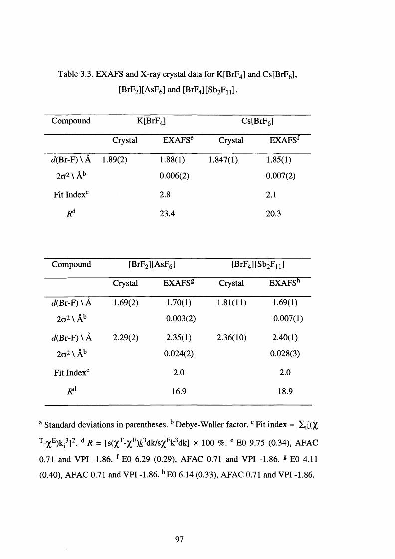
Table 3.3. EXAFS and X-ray crystal data for K[BrF4] and Cs[BrF6],
[BrF2 ][AsF6] and [BrF4 ][Sb2 Fn ].
Compound K[BrF4] Cs[BrF6]
Crystal EXAFSe Crystal EXAFSf
</(Br-F) \ A 1.89(2) 1.88(1) 1.847(1) 1.85(1)
2a2 \ Ab 0.006(2) 0.007(2)
Fit Index0 2 . 8 2 . 1
Rd 23.4 20.3
Compound [BrF2 ][AsF6] [BrF4 ][Sb2 F n ]
Crystal EXAFSg Crystal EXAFSh
(/(Br-F) \ A 1.69(2) 1.70(1) 1.81(11) 1.69(1)
2 o 2 \ Ab 0.003(2) 0.007(1)
(/(Br-F) \ A 2.29(2) 2.35(1) 2.36(10) 2.40(1)
2 <J2 \ Ab 0.024(2) 0.028(3)
Fit Index0 2 . 0 2 . 0
Rd 16.9 18.9
a Standard deviations in parentheses. Debye-Waller factor. c Fit index = Zj[(%
T-%E)ki3]2. d R = [s(XT-XE)£3 dk/sXEk3 dk] x 100 %. e E0 9.75 (0.34), AFAC
0.71 and VPI -1.86. f E0 6.29 (0.29), AFAC 0.71 and VPI -1.86. g E0 4.11
(0.40), AFAC 0.71 and VPI -1.86. h E0 6.14 (0.33), AFAC 0.71 and VPI -1.86.
97
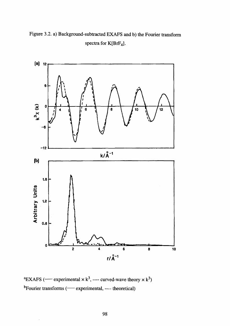
Figure 3.2. a) Background-subtracted EXAFS and b) the Fourier transform
spectra for K[BrF4].
-8
-12° - i
k / A 1(b)
1.8
CO
k.< 0.6
4 62 8 10o _
r /A
aEXAFS ( experimental x k3, — curved-wave theory x k3)
bFourier transforms ( experimental, — theoretical)
98
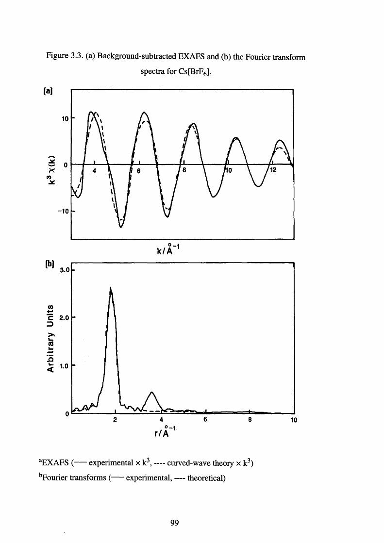
Figure 3.3. (a) Background-subtracted EXAFS and (b) the Fourier transform
spectra for Cs[BrF6].
(a)
-10
(b) 3.0
(0
C 2.0 D>.w(0
3k -
r / A
aEXAFS ( experimental x k3, — curved-wave theory x k3)
bFourier transforms ( experimental, — theoretical)
99
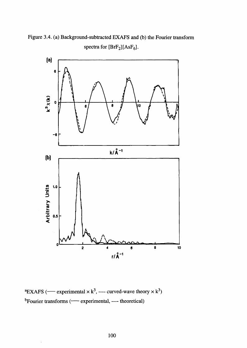
Figure 3.4. (a) Background-subtracted EXAFS and (b) the Fourier transform
spectra for [BrF2][AsF6].
(a)
6
0
6
0k / A 1
(b)
1.0c3
(01 -4-»3 0.5<
v - ■
r /A
aEXAFS (----- experimental x k3, — curved-wave theory x k3)
bFourier transforms ( experimental, — theoretical)
100
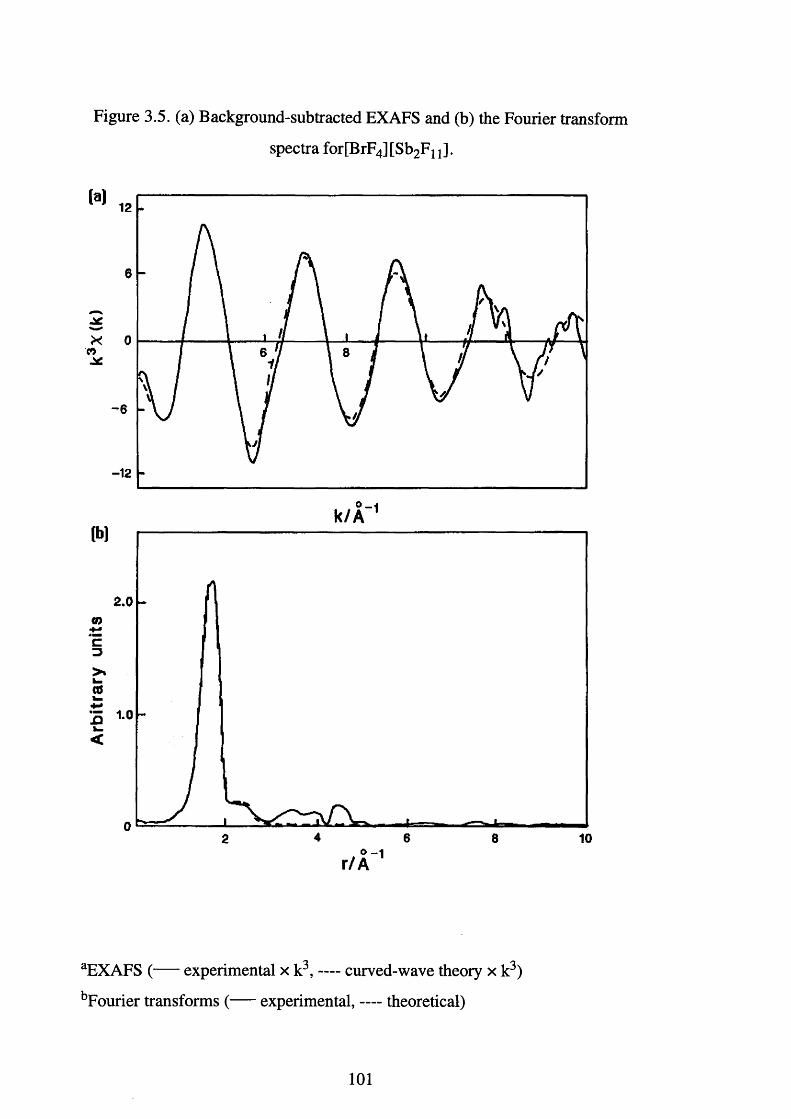
Figure 3.5. (a) Background-subtracted EXAFS and (b) the Fourier transform
spectra for[BrF4] [Sb2F x x ].
C O
-12
(b)
2.00)
1.0
<
4 6 8 102
aEXAFS ( experimental x k3, — curved-wave theory x k3)
bFourier transforms ( experimental, — theoretical)
101
1.69 A, and the formal oxidation state of the bromine does not significantly
affect the bond length.
It is noted that the single crystal data presented for [BrF4]+ is not
particularly good (R=0.14). The crystallographic experimental data did not
allow precise determination of bond lengths and angles, however, at the time
this was considered unimportant as the structure determination provided
information about the overall structure of this interesting adduct. A comparison
of the crystallographic and EXAFS data (Table 3.3) for [BrF4]+ shows that the
crystallographically determined bond length of 1.81(11) A was not very precise
and, more importantly, is indicative of an anionic Br-F bond distance. The
value obtained using EXAFS spectroscopy, 1.69(1) A, provides a far more
meaningful representation of the Br-F bond length. For the cations, [BrF2]+ and
[BrF4]+, EXAFS spectroscopy is able to verify the presence of bridging
fluorines at 2.35(1) and 2.40(1) A respectively.
As can be seen in the EXAFS spectra presented in Figures 3.2 to 3.5,
extra shells were observed in each case at distances above 3 A from the central
bromine atoms. Attempts were made to fit these shells and, in each case, the
result showed an improvement in the R value. The shells, however, were found
to be statistically in sign ifican t^ and were not included in the fits presented in
this Chapter.
The hexafluorobromine (VII) cation was synthesised by Gillespie and
Schrobilgen[98' 10°l in 1976. Although no crystallographic data are available,
characterisation by 19F NMR and Raman spectroscopy is reported. The 19F
NMR spectra recorded in HF at room temperature showed two overlapping
1 :1 :1 :1 quartets at 8339.4 ppm. The two quartets are assigned to [7 9 BrF6]+ and
[8 1 BrF6]+ and arise from spin-spin coupling of the six equivalent fluorines with
79Br and 8 1 Br, both with 7=3/2. The equal intensities of the quartets is in
accordance with the natural abundance of the two bromine isotopes (7 9 Br,
50.57% and 81Br 49.43%) and the ratio / ( 1 9 F-8 1 B r):/(1 9 F-7 9 Br) is in agreement
with the gyromagnetic ratios y8 1 Br:y79Br = 1.0778.
102
The hexafluorobromine (V) anion has been characterised recently^ 1 0 1 ̂
and the low temperature (-40°C) 19F NMR spectrum shows the same features
as those described above. This is contrary to previous NMR experiments^102̂
which failed to observe Br-F coupling even at temperatures of -60°C. The
fluorine resonances occur at lower frequency, 5100.6 ppm, which is a result of
the lower oxidation state of the central bromine. The observation of this
coupling indicates an octahedral structure implying that the valence electrons
are occupying the sterically inactive As orbital.
Bromine is thought to have a maximum co-ordination number of six, the
same as chlorine, whereas iodine has a maximum co-ordination number of 8 .
This was used to explain the reactions of [BrF6]+ and [IF6]+ with NOF (Eqn.’s
3.4 and 3.5).
[BrF6 ]+[AsF6]' + NOF -> BrF5 + F2 + [NO]+[AsF6]’ Eqn. 3.4.
[IF6 ]+[AsF6]" + NOF -> IF7 + [NO]+[AsF6r Eqn. 3.5.
However, the crystal structure of [BrF4 ]+[Sb2 F 11]' in d ic a te s^ that the
bromine centre has a co-ordination number of seven. Distortion within the
cation indicates the presence of a sterically active lone pair of electrons,
therefore, the crystal structure showed the bromine to be pseudo-hepta
coordinate. The crystal data showed four fluorines bound at an average distance
of 1.81(11) A and two bridging fluorines, to the neighbouring [Sb2 Fn]"
molecules, at a distance of 2.36(10) A. The EXAFS data has shown that the Br-
F terminal distances are 1.69(1) A. This seems to be a more realistic value in
the context of the nature of the charge on the species.
For the cations [BrF2]+ and [BrF4]+ the lone pairs of electrons appear to
adopt sterically active roles, contrary to what is found in [BrF6] \ This maybe a
reflection of the inability of bromine to exist with a co-ordination number of
seven. Further work is needed to establish whether bromine does exist with a
103

co-ordination number of seven. The steric crowding in BrF7 would presumably
be less than that for [BrF4]+ as, according to VSEPR theory, a non-bonding pair
of electrons would exhibit greater repulsion than a bromine fluorine single
bond.
3.13. The Synthesis and EXAFS Characterisation of Caesium
Bromine-Oxide Tetrafluoride.
The existence of K[BrOF4], has been reported by both B o u g o n ^ and
GillespieJ17̂ Bougon obtained K[BrOF4] by the reaction of K [B r03] with a
large excess of BrF5 at 80°C in the presence of fluorine. Although this method
reportedly yields a pure product, the course of the reaction is difficult to control
and K[BrF4] is usually obtained as the only product. Gillespie reported that the
reaction between K[BrF6] and K [B r03] in CH3CN solution produces a mixture
of K [B r0 2 F2] and K[BrOF4] (Eqn. 3.6). The separation of the two products
relies on the solubility of K[BrOF4] in CH3CN compared with the insolubility
of K [B r0 2 F2].
K[BrF6] + K [B r03] -> K[BrOF4] + K [Br0 2 F2] Eqn. 3.6.
In 1978, Christe reported an improved synthesis of [BrOF4]‘ salts
The reaction of K [Br04] or Cs[Br04] with BrF5 and F2 led to K[BrOF4] and
the previously unknown Cs[BrOF4]. Although this method results in essentially
pure products in high yield, the required [Br04]" salts are difficult to prepare.
The reaction of the caesium salt, Cs[Br04], occurs at room temperature over
thirty hours with 1 0 0 % conversion, whereas, the potassium salt requires ninety
five hours at 80°C with only 70% conversion.
In 1987 Christe and Wilson proposed a new one-step synthesis to
[BrOF4]‘ saltsP 6 ̂ They reported that the reactions of an excess of BrF5 with
104
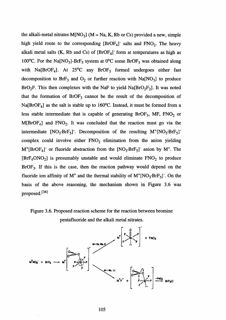
the alkali-metal nitrates M[NOs] (M = Na, K, Rb or Cs) provided a new, simple
high yield route to the corresponding [BrOF4]' salts and F N 02. The heavy
alkali metal salts (K, Rb and Cs) of [BrOF4]' form at temperatures as high as
100°C. For the N a[N 0 3 ]-BrF5 system at 0°C some BrOF3 was obtained along
with Na[BrOF4]. At 25°C any BrOF3 formed undergoes either fast
decomposition to BrF3 and 0 2 or further reaction with N a[N 03] to produce
B r0 2 F. This then complexes with the NaF to yield N a[Br0 2 F2]. It was noted
that the formation of BrOF3 cannot be the result of the decomposition of
Na[BrOF4] as the salt is stable up to 160°C. Instead, it must be formed from a
less stable intermediate that is capable of generating BrOF3, MF, FN 0 2 or
M[BrOF4] and F N 02. It was concluded that the reaction must go via the
intermediate [N 0 3 -BrF5]". Decomposition of the resulting M+[N 0 3 -BrF5]‘
complex could involve either F N 0 2 elimination from the anion yielding
M+[BrOF4]" or fluoride abstraction from the [N 0 3 *BrF5]‘ anion by M+. The
[BrF4 0 N 0 2] is presumably unstable and would eliminate FN 0 2 to produce
BrOF3. If this is the case, then the reaction pathway would depend on the
fluoride ion affinity of M+ and the thermal stability of M+[N 0 3 *BrF5] \ On the
basis of the above reasoning, the mechanism shown in Figure 3.6 was
proposed P®
Figure 3.6, Proposed reaction scheme for the reaction between bromine
pentafluoride and the alkali metal nitrates.
M^NOa' + BrF5
105
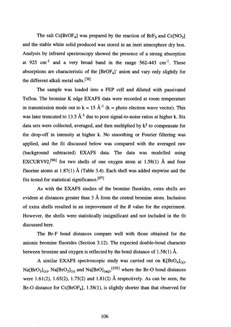
The salt Cs[BrOF4] was prepared by the reaction of BrF5 and Cs[N 03]
and the stable white solid produced was stored in an inert atmosphere dry box.
Analysis by infrared spectroscopy showed the presence of a strong absorption
at 925 cm - 1 and a very broad band in the range 562-443 cm"1. These
absorptions are characteristic of the [BrOF4]' anion and vary only slightly for
the different alkali metal saltsP®
The sample was loaded into a FEP cell and diluted with passivated
Teflon. The bromine K edge EXAFS data were recorded at room temperature
in transmission mode out to k = 15 A"1 (k = photo electron wave vector). This
was later truncated to 13.5 A"1 due to poor signal-to-noise ratios at higher k. Six
data sets were collected, averaged, and then multiplied by k3 to compensate for
the drop-off in intensity at higher k. No smoothing or Fourier filtering was
applied, and the fit discussed below was compared with the averaged raw
(background subtracted) EXAFS data. The data was modelled using
EXCURV92J961 for two shells of one oxygen atom at 1.58(1) A and four
fluorine atoms at 1.87(1) A (Table 3.4). Each shell was added stepwise and the
fits tested for statistical significance J 9 7 1
As with the EXAFS studies of the bromine fluorides, extra shells are
evident at distances greater than 3 A from the central bromine atom. Inclusion
of extra shells resulted in an improvement of the R value for the experiment.
However, the shells were statistically insignificant and not included in the fit
discussed here.
The Br-F bond distances compare well with those obtained for the
anionic bromine fluorides (Section 3.12). The expected double-bond charactero
between bromine and oxygen is reflected by the bond distance of 1.58(1) A.
A similar EXAFS spectroscopic study was carried out on K [Br04](S),
N a[B r03](s), N a[Br02](s) and Na[BrO](aq),̂ 103̂ where the Br-O bond distances
were 1.61(2), 1.65(2), 1.75(2) and 1.81(2) A respectively. As can be seen, the
Br-O distance for Cs[BrOF4], 1.58(1), is slightly shorter than that observed for
106
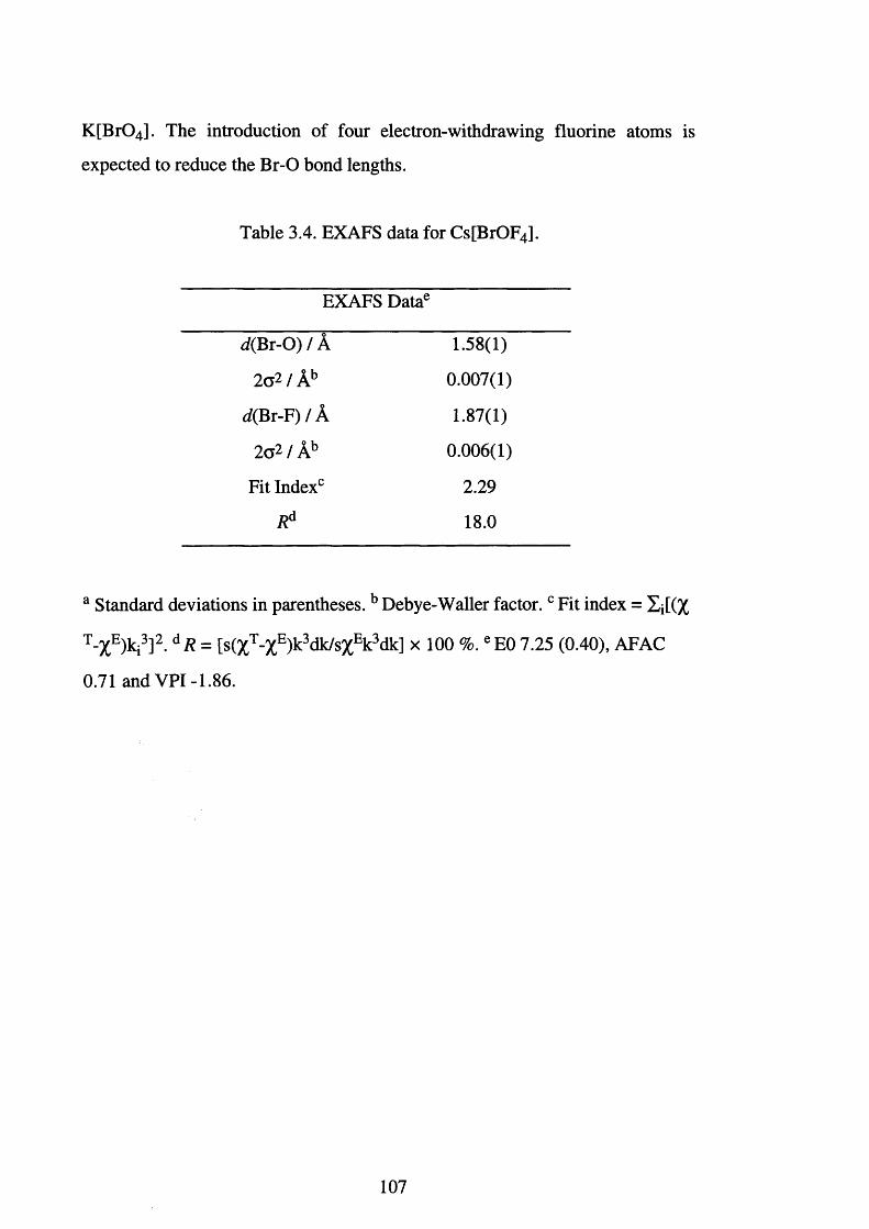
K [B r04]. The introduction of four electron-withdrawing fluorine atoms is
expected to reduce the Br-O bond lengths.
Table 3.4. EXAFS data for Cs[BrOF4].
EXAFS Datae
rf(Br-0 ) / A 1.58(1)
2c2 / Ab 0.007(1)
rf(Br-F) / A 1.87(1)
2a2 / Ab 0.006(1)
Fit Index0 2.29
Rd 18.0
a Standard deviations in parentheses. b Debye-Waller factor. c Fit index = Xj[(%
T-XE)ki3]2. dR = [s(XT-%E)k3 dk/s%Ek 3 dk] x 100 %. e E0 7.25 (0.40), AFAC
0.71 and V P I-1.86.
107
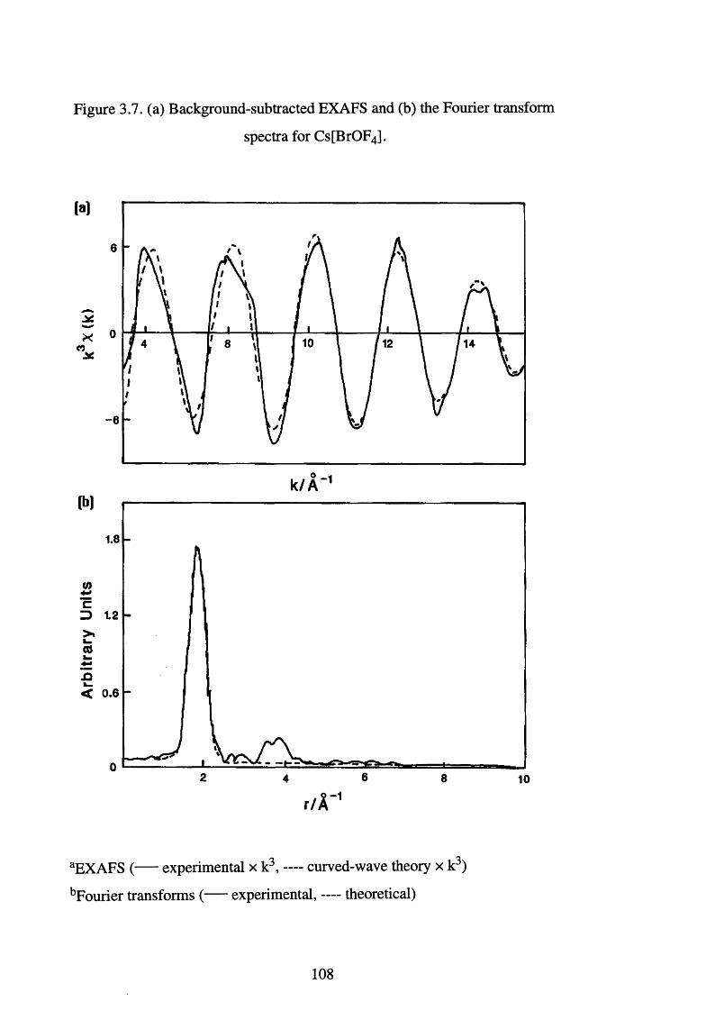
Figure 3.7. (a) Background-subtracted EXAFS and (b) the Fourier transform
spectra for Cs[BrOF4].
M
-6
o -k / A 1
1.8
Z> 12
< 0.6
62 84 10
r /V
aEXAFS ( experimental x k3, — curved-wave theory x k3)
bFourier transforms ( experimental, —- theoretical)
108
3.14. The Synthesis of Potassium Perbromate.
The synthetic routes to the perbromate anion are outlined in Section
3.10. Oxidation of the bromate anion in sodium hydroxide solution using
elemental f l u o r i n e p r o v i d e s the best route (Eqn. 3.7).
[BrO3r + F2 + 2 OH* [Br04]' + 2 F + H20 Eqn. 3.7.
Initial attempts necessitated a slow rate of addition of fluorine and led to
reaction times of 2 to 3 days. However, it was realised that it is necessary to
complete the fluorination and isolation of the product within a single day.
Faster flow rates were attained with the construction of a new metal vacuum
line in a well vented, low population area and the fluorination stage was cut to a
few hours. However, care had to be taken to cool the reaction mixture because
the fast rates of addition of fluorine have the potential to lead to exotherms and
ignition of the solvent vapour.
Potassium perbromate was dried under dynamic vacuum at 150°C for 12
hours, and stored in an inert atmosphere dry box. An infrared spectrum of the
solid as a Nujol mull showed its characteristic absorptions to be present at 798
and 410 cm-1.
The 81Br NMR spectrum (7=3/2, 49.43% abundance) was recorded for
K [B r04] and referenced to aqueous KBr (1 mol dm-3), the values being
corrected to infinite dilution using the published dataJ103̂ The 81Br NMR
resonance of [B r04]" was observed at 52470, relative to infinitely dilute
aqueous Br", in good agreement with the reported^103̂ value of 52476 ppm.
109
3.15. The Synthesis of Perbromyl Fluoride.
The synthesis of perbromyl fluoride was first reported by Appleman et
al. in 1 9 6 9 and involved the reaction between potassium perbromate and
antimony pentafluoride in anhydrous hydrogen fluoride. The compound is
highly volatile and possesses a vapour pressure of 56 torr at -50°C.
Due to the problems encountered during the synthesis of the other
bromine oxide fluoride compounds, the reactions between K [Br04] and SbF5,
SbF5 -AHF, BrF5-AHF or AsF5-AHF were re-examined to establish which
provided the most convenient route to B r0 3 F. Using 19F NMR spectroscopy,
the reactions were all shown to produce B r0 3 F. The preferred route employed
the use of AHF and BrF5, the reason for this was solely the ease of transfer of
AHF and BrF5 as opposed to the less volatile and more viscous SbF5.
Perbromyl fluoride decomposes slowly at room temperature and this was
evidenced by the formation of Br2. This discouraged us from using trap to trap
distillation as a means of purification. Instead, the reaction products were
distilled at low temperature, -84°C, at which temperature the vapour pressures
of B r0 3 F, AHF and BrF5 are 5, 2 and 0 torr respectively. The volatile products
were condensed, under static vacuum, into a second FEP tube which contained
dried NaF. The NaF formed an involatile adduct with trace amounts of HF,
whereas, B r0 3F and NaF did not react.
As already stated, B r03F decomposes slowly at room temperature to
produce Br2. The Br2 can be readily removed by the condensation of F2 into the
FEP tube at 196°C. On warming to room temperature the Br2 is oxidised to
BrF3, which then reacts with NaF to form an involatile adduct. Therefore, the
NaF serves two purposes, the removal of HF and BrF3, and facilitates the
preparation of pure B r0 3 F. No decomposition was observed to occur if the
B r0 3F is stored at liquid nitrogen temperatures.
The reaction between K[Br04] and BrF5, using AHF as the solvent has
been previously investigated^21̂ The reaction apparently occurs according to
110
Equation 3.8. Figure 3.8 shows the 19F NMR spectrum recorded for the
reaction medium at -59 °C. The AX4 pattern generated by the BrF5 was
unresolved at room temperature. However, at -59°C, the multiplicity was
resolved: 8 Fa 271.9 and 8 Fe 135.2 ppm. Also apparent was a resonance at
8274.2 ppm due to the presence of B r03F (cf. neat B r0 3 F, 8274 ppm, -80
°C)J3TI
2 K [B r04] + BrF5 + 2 HF -> 2 B r0 3F + B r02F + 2 K[HF2] Eqn. 3.8.
The presence of B r02F was used by Spekkens^2^ to explain the poor
resolution observed for the 19F NMR spectrum of the reaction media. Fluorine-
19 NMR experiments performed by Spekkens failed to detect the presence of
B r0 2 F, although, it was detected using Raman spectroscopy. Gillespie and
Spekkens report the 19F NMR chemical shift for B r02F to be 8210 ppm when
recorded as a solution in BrF5 J37̂ The presence of B r02F cannot be verified
using low temperature 19F NMR spectroscopy, this seems strange in view of
the smooth base line observed in the region of 8210 ppm and the high
resolution of the spectrum, discounting the presence of any fluxionality.
Therefore, the reaction described here clearly does produce B r0 3 F, however,
whether this is exactly as outlined in Equation 3.8 is doubtful.
The reaction of K [Br04] with XF5 -AHF, where X = Sb or As, is thought
to go via a different reaction pathway. However, none of the intermediate
species have been observed. Work has demonstrated that the reaction is not that
shown in Equation 3.9.
K [B r04] + AsF5 —» B r0 3F + K[AsOF4] Eqn. 3.9.
I l l
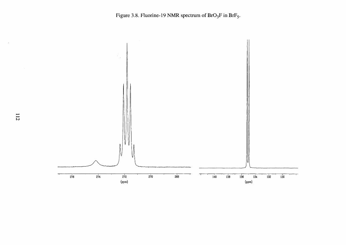
Figure 3.8. Fluorine-19 NMR spectrum of B r0 3F in BrF5.
t o
276 274 272
(ppm )270 268 140 138 136 134
(ppm )132 130
Raman spectroscopy has shown that neither AsOF3 nor K[AsOF4] are
present^21! An alternative mechanism is that proposed for the formation of
CIO3 F from [CIO4 ]" under the same conditions.^ Although numerous
speculative opinions have been expressed for this system, it seems unlikely that
the formation of B r0 3F involves a mechanism where [B r03]+ is an
intermediate. Furthermore, the high yields, > 96 %, would not be expected in
view of the likely instability of [B r03]+. It seems more likely that the
mechanism involves protonated perbromic acid as shown in Scheme 3.1.
Scheme 3.1. Proposed reaction pathway for the
formation of perbromyl fluoride.
4 HF + 2 XF5 -> 2 [H2 F]+ + 2 [XF6]‘
2 [H2 F]+ + [Br04r -> [H2 O Br03]+ + 2 HF
[H2 O B r03]+ + HF -» B r03F + [H3 0 ] +
overall: [Br04] ' + 3 HF + 2X F 5 -> B r03F + [H3 0 ] + + 2 [XF6]'
X = Sb or As.
The formation of perbromyl fluoride is more likely to involve the
nucleophilic displacement of H20 by F , rather than the heterolytic cleavage of
the Br-OH2 bond in [H2 0 B r0 3]+ to give H20 and [Br03]+ followed by reaction
of [B r03]+ with HF.
113
3.16. The Attempted Synthesis of Bromine Oxide Trifluoride.
The reaction between the heavy alkali metal nitrates, M [N 03] (M = K,
Rb or Cs), and bromine pentafluoride produces the corresponding
tetrafluorobromate (V) salt. The yield for this reaction is quantitative for the
caesium reaction and decreases as Group 1 is ascended. It was noted by Christe
et al. that the reaction between N a[N 03] and BrF5 3̂6̂ did not produce
Na[BrOF4] as the only product. They observed that BrOF3 was also formed,
along with some Na[BrF4], which was presumably formed via the
decomposition of the BrOF3 as shown in Equations 3.10 and 3.11 (Figure 3.6).
BrOF3 —» BrF3 + V i0 2 Eqn. 3.10.
NaF + BrF3 -> Na[BrF4] Eqn. 3.11.
The route by which the above reaction occurs (see Section 3.13) depends
solely on the fluoride ion affinity of the alkali metal. On the basis of hard-soft
acid-base principles, it was reasoned that L i[N 03] should form BrOF3 in the
highest yield due to the high fluoride affinity of the lithium cation. Indeed,
Christe et al. reported that when L i[N 03] was allowed to react with an excess
of BrF5 at 0°C over twenty days, BrOF3 was formed in essentially quantitative
yield.
The reaction was attempted at 0°C over a period of twenty days in a
nickel reaction vessel which was shaken several times daily. The vessel was
attached to a metal line and the volatile materials were distilled through a trap
at -64°C under dynamic vacuum. At this temperature, BrF5 and F N 0 2 do not
collect and any solid trapped should have been due to the presence of BrOF3,
but no solid was collected. Five attempts were made to synthesis BrOF3.
However, 19F NMR spectroscopy of the residual solid dissolved in CH3CN
114
showed only the presence of [BrF4]', suggesting that BrOF3 may have been
formed but had subsequently decomposed according to Equation 3.10. Similar
results were observed when the reaction was carried out at -10 and -20°C and
with larger excesses of BrF5.
A second approach for the production of bromine oxide trifluoride was
attempted. This involved the reaction between K[BrOF4] and a weak Lewis
acidJ17̂ Bromine oxide trifluoride can be obtained by dissolving K[BrOF4] in
AHF at low temperature. On wanning the K[BrOF4]-HF mixture to room
temperature BrOF3 and K[HF2] are formed (Eqn. 3.12).
K[BrOF4] + HF —» BrOF3 + K[HF2] Eqn. 3.12.
The HF can be removed by pumping the mixture at -60°C to leave a
mixture of BrOF3 and K[HF2]. The BrOF3 cannot simply be removed under
dynamic vacuum as the reaction is reversible. This problem can be overcome
by condensation of BrF5 on to the mixture which solubilises the BrOF3 but not
the K[HF2] . Decantation of the solution affords separation. The BrF5 can then
be removed at low temperature to leave BrOF3.
The problem with this preparation is that a pure source of K[BrOF4] is
required. Gillespie and Spekkens described that a mixture of K[BrOF4] and
K [B r0 2 F2] could be obtained from the fluorine exchange reaction between
K [B r03] and K[BrF6] in CH3 C N J17̂ The separation of the two products relies
on the slight solubility of K[BrOF4] over the apparent insolubility of
K [B r0 2 F2] in CH 3 CN. A mixture of K [Br0 2 F2] and K[BrOF4] and CH3CN
was shaken for two hours at room temperature. The liquid was then filtered into
a second vessel. On the basis of what Gillespie and Spekkens reported removal
of the CH3CN should have produced a white solid. In our hands, however, no
white solid was deposited on any of the several times the reaction was repeated.
115
3.17. The attempted preparation of Bromyl Fluoride.
Two synthetic procedures were investigated as a possible route to
bromyl fluoride, B r0 2 F. The reaction between K [B r03] and BrF5 and a
catalytic amount of HF reportedly produces K [Br0 2 F2], K[BrOF4] and
B r0 2 F J 15,16,17̂ The above mixture was stirred at room temperature for two
hours. The resultant mixture was brown, consistent with Gillespie's
observations, and was presumably so due to the formation of bromine. The
volatile materials were pumped under a dynamic vacuum through a trap at -48
°C (n-hexyl alcohol / C 0 2 (S)), at which temperature B r02F should have
condensed. No material was collected in the trap indicating that B r02F had not
been formed.
During the reactions a large volume of gas was evolved which was
presumably oxygen since it was not totally condensable at liquid nitrogen
temperatures. Analysis of the solid product by 19F NMR spectroscopy showed
only the presence of [BrF4] \ The solvent used was CH 3 CN, in which
K [B r0 2 F2] is insoluble and K[BrOF4] is only slightly soluble. Infrared analysis
of the solid was uninformative due to the large number of absorptions which
coincided and the broadness associated with them. The reaction was repeated
four times with no change in the result.
The second synthetic route relies on the isolation of K [B r0 2 F2] . As was
the case in Section 3.16, the reaction between K [Br0 2 F2] and HF yields B r0 2F
and K[HF2].[17] Unlike the K[HF2 ]-BrOF3 mixture, B r02F can be removed
from the K[HF2 ]-B r02F mixture without the reverse reaction occurring;
indicating that BrOF3 is a stronger fluoride ion acceptor than B r0 2 F. As a
consequence of not being able to separate the mixture of K [Br0 2 F2] and
K[BrOF4] this reaction could not be attempted.
116
3.18. Conclusion.
Little progress has been made in the synthesis of new bromine oxide
fluorides. However, it was felt that significant knowledge had been gained
about approaches that had the potential to be successful with a concerted effort.
However, as was envisaged, the use of EXAFS spectroscopy provided an
excellent means by which to obtain structural data on this fundamentally
important class of compounds. EXAFS spectroscopy was successfully used to
characterise the model compounds K[BrF4], Cs[BrF6], [BrF2 ][AsF6] and
[BrF4 ][Sb2 F 11]. The expected trends in Br-F bond lengths have been clearly
illustrated and the improvement in the data available for [BrF4 ][Sb2 Fn ]
demonstrates the problems encountered when trying to characterise these type
of compounds using single crystal techniques.
The use of EXAFS spectroscopy has permitted the anion [BrOF4]" to be
structurally characterised for the first time. The Br-F bond lengths are in good
agreement with established trends highlighted for the bromine fluoride ions and
the Br-O bond length also seems very reasonable.
The isolation of K [Br04] proved difficult. However, once isolated, the
synthesis of B r0 3F opened a potential route to new bromine (VII) oxide
fluorides. The possibility of performing EXAFS spectroscopy on low
temperature bromine oxide fluorides also offered the potential to obtain
structural data on otherwise, highly reactive, gaseous materials.
Two major problems were encountered mid-way through the second
year of research. The use of EXAFS spectroscopy relies on the allocation of
time at the synchrotron radiation source in Daresbury. No time was allocated to
the Leicester Fluorine Group during this year and, consequently, the
characterisation of new species which had been made was not possible.
Secondly, new regulations about the transportation of BrF5, which is a vital
reagent in this area of chemistry, meant that this was no longer accessable, and
117
the delivery of a new cylinder would have taken in excess of a year. As a
consequence of this, and the very slow progress being made within this area, a
decision was made to stop the work and move into the areas described in
Chapters Two and Four.
However, as outlined in Section 3.11, a lot of work is still needed to
determine whether this class of compounds can be expanded. A determined
effort would undoubtedly unearth new synthetic routes to bromine (VII) oxide
fluorides. The generation of new bromine (VII) oxide fluorides will take severe
conditions, but the use of [KrF]+ or [Kr2 F3]+ and the laser photolysis of liquid
fluorine are still to be investigated. These reagents and techniques such as low
temperature infrared and EXAFS spectroscopy offer the most realistic chances
of success.
118
References Chapter Three
[1] R. J. Gillespie, Molecular Geometry, Van Nostrand Reinhold, London,
1972.
[2] R. J. Gillespie, Chem. Soc. Rev., 1992, 59.
[3] A. J. Downs and C. J. Adams, Comprehensive Inorganic Chemistry,
Pergamon Press, Oxford, 1973, 2, 1386-96 and references cited therein.
[4] Y. Macheteau and J. Gillardeau, B ull Soc. Chem. Fr., 1967,11, 4075.
[5] K. O. Christe, R. D. Wilson and C. J. Schack, Inorg. Nucl. Chem. Lett.,
1975,11, 161.
[6 ] K. O. Christe and C. J. Schack, Adv. Inorg. Chem. Radiochem., 1976,
18, 319 and references cited therein.
[7] W. H. Basualdo and H. J. Schumacher, Angew. Chem., 1955, 67, 231.
[8 ] C. R. Parent and M. C. L. Gerry, J. Chem. Soc., Chem. Commun., 1972,
285.
[9] C. R. Parent and M. C. L. Gerry, J. Mol. Spectrosc., 1974, 49, 343.
[10] D. K. Huggins and W. B. Fox, US. Pat., 3 423 168, 1969.
[11] D. K. Huggins and W. B. Fox, Inorg. Nucl. Chem. Lett., 1970, 6 , 337.
[12] K. O. Christe and E. C. Curtis, Inorg. Chem., 1972,11, 35.
[13] K. O. Christe, US. Pat., 3 879 526, 1975.
[14] K. O. Christe, Inorg. Chem., 1973,12, 1580.
[15] M. Schmeisser and K. Brandle, Adv. Inorg. Chem. Radiochem., 1963, 5,
411 and references cited therein.
[16] R. Bougon and G. Tantot, C. R. Seances Acad. Sci. Paris, 1975, C 281,
271.
[17] R. J. Gillespie and P. Spekkens, J. Chem. Soc. Dalton Trans., 1976,
2391.
[18] R. J. Gillespie and P. Spekkens, J. Chem. Soc., Chem. Commun., 1975,
314.
119
[19] R. J. Gillespie and P. Spekkens, J. Chem. Soc. Dalton Trans., 1977,
1539.
[20] K. O. Christe, E. C. Curtis and E. Jacob, Inorg. Chem., 1978,17, 2744.
[21] P. Spekkens, Ph.D. Thesis, McMaster University, Canada, 1977.
[22] K. O. Christe and E. C. Curtis, Inorg. Chem., 1973,12, 2879.
[23] M. Aldehelm and E. Jacob, Angew. Chem. Int. Ed. Engl, 1977,16, 461.
[24] R. Bougon, P. Joubert and G. Tantot, J. Chem. Phys., 1977, 6 6 ,1562.
[25] R. E. Aynsley, R. Nichols and P. L. Robinson, J. Chem. Soc., 1953, 623
and references cited therein.
[26] H. A. Carter and F. Aubke, Inorg. Chem., 1971,10, 2296.
[27] D. Pilipovic, C. B. Lindahl, C. J. Schack, R. D. Wilson and K. O.
Christe, Inorg. Chem., 1972,11, 2189.
[28] R. Bougon, J. Isabey and P. Plurien, Compt. Rend., 1970, 271C, 1366.
[29] D. Pilipovich and C. J. Schack, US. Pat., 3 692 476, 1972.
[30] H. Oberhammer and K. O. Christe, Inorg. Chem., 1982, 21, 273.
[31] K. O. Christe and E. C. Curtis, Inorg. Chem., 1972,11, 2196.
[32] K. O. Christe, C. J. Schack and D. Pilipovich, Inorg. Chem., 1972,11,
2205.
[33] K. O. Christe and E. C. Curtis, Inorg. Chem., 1972,11, 2212.
[34] K. O. Christe, C. J. Schack and D. Pilipovich, Inorg. Chem., 1972,11,
2205.
[35] R. Bougon and T. Bui Huy, C. R. Seances Acad. Sci., Ser. C, 1976, 283,
461.
[36] W. W. Wilson and K. O. Christe, Inorg. Chem., 1987, 26, 916.
[37] R. J. Gillespie and P. H. Spekkens, Isr. J. Chem., 1978,17, 11.
[38] K. O. Christe, E. C. Curtis and R. Bougon, Inorg. Chem., 1978,17,
1533.
[39] R. Bougon, T. Bui Huy, P. Charpin, R. J. Gillespie and P. H. Spekkens,
J. Chem. Soc., Dalton Trans., 1979, 6 .
[40] N. Keller and G. J. Schrobilgen, Inorg. Chem., 1981, 20, 2118.
120
[41] J. W. Viers and H. W. Braid, J. Chem. Soc., Chem. Commun., 1967,
1093.
[42] K. O. Christe, R. D. Wilson, E. C. Curtis, W. Kuhlmann and W.
Sawodny, Inorg. Chem., 1978,17, 533.
[43] Gall J. F., Kirk Othmer Encyclopedia o f Chemical Technology, Wiley,
London, 2nd edn., 1966, vol. 9, 598.
[44] A. H. Clark, B. Beagley and D. W. J. Cruickshank, J. Chem. Soc.,
Chem. Commun., 1968,14.
[45] W. A. Sheppard, Tetrahedron Lett., 1969, 83.
[46] F. A. Cotton and G. Wilkinson, Advanced Inorganic Chemistry, Wiley,
New York, 4th edn., 1980, 570.
[47] D. Pilipovich, H. H. Rogers and R. D. Wilson, Inorg. Chem., 1972,11,
2192.
[48] H. Rude, R. Benoit and O. Hartmanshenn, Nucl. Sci. Abstr., 1972, 26,
6528.
[49] E. H. Appleman, J. Amer. Chem. Soc., 1968, 90, 1900.
[50] E. H. Appleman, Inorg. Synth., 1973,14, 29.
[51] E. H. Appleman, B. Beagley, D. W. J. Cruickshank, A. Foord, S. Rustad
and V. Ulbrecht, J. Mol. Struct., 1976, 35, 139.
[52] M. Schmeisser and K. Lang, Angew. Chem., 1955, 6 7 ,156.
[53] R. C. Paul, K. K. Paul and K. C. Malhotra, Indian J. Chem., 1970, 8 ,
1030.
[54] K. O. Christe and R. D. Wilson, Inorg. Chem., 1973,12, 1356.
[55] K. O. Christe, R. D. Wilson and E. C. Curtis, Inorg. Chem., 1973,12,
1358.
[56] E. N. Sloth, L. Stein and C. W. Williams, J. Phys. Chem., 1969, 73, 278.
[57] A. Engelbrecht and P. Peterfly, Angew. Chem. Int. Ed. Engl., 1969, 8 ,
768.
[58] D. Lay cock, Ph.D. Thesis, University of Leicester, 1981 and references
cited therein.
121
[59] R. G. Syvret, Ph.D. Thesis, McMaster University, Canada, 1987.
[60] A. Engelbrecht, O. Mayr, G. Ziller and E. Schandara, Montash. Chem.,
1974,105, 796.
[61] A. Engelbrecht, P. Peterfly and E. Schandara, Z. Anorg. Allg. Chem.,
1971,384, 202.
[62] K. O. Christe. R. D. Wilson and C. J. Schack, Inorg. Chem., 1981, 20,
2104.
[63] H. A. Carter, J. N. Ruddick, J. R. Sams and F. Aubke, Inorg. Nucl.
Chem. Let., 1975,11, 29.
[64] K. Ztichner and O. Glemser, Angew. Chem. Int. Ed. Engl., 1972,11,
1094.
[65] H. Selig and U. El-Gad, Inorg. Nucl. Chem., Herbert H. Hyman
Memorial Volume 1976, Pergamon Press, ed. J. J. Katz and I. Sheft,
pg. 91.
[6 6 ] R. J. Gillespie and J. W. Quail, Proc. Chem. Soc., 1963, 278.
[67] N. Barlett and L. E. Levchuk, Proc. Chem. Soc., 1963, 342.
[6 8 ] J. H. Holloway, H. Selig and H. H. Classen, J. Chem. Phys., 1971, 54,
4305.
[69] C. J. Schack and K. O. Christe, J. Fluorine Chem., 1990, 49, 167.
[70] L. S. Bartlett, F. B. Clippard and J. E. Jacob., Inorg. Chem., 1976,15,
3009.
[71] M. Brownstein, R. J. Gillespie and J. P. Krasznai, Can. J. Chem., 1978,
2253.
[72] Ali-Reza Mahjoub and K. Seppelt, J. Chem. Soc., Chem. Commun.,
1991, 840.
[73] K. O. Christe, J. C. P. Saunders, G. J. Schrobilgen and W. W. Wilson, J.
Chem. Soc., Chem. Commun., 1991, 837.
[74] O. Ruff and H. King, Z. Anorg. Allg. Chem., 1930,190, 270.
[75] T. D. Cooper, F. N. Dost and C. H. Wang, J. Inorg. Nucl. Chem., 1972,
34, 3564.
122
[76] L. Andrews, F. K. Chi and A. Arkell, J. Am. Chem. Soc., 1974, 96,
1997.
[77] F. von Stadion, Gilberts Ann., 1816, 52, 197.
[78] F. Ammurmiiller and G. Magnus, Pogg. Ann., 1833, 28, 514.
[79] E. H. Appleman, J. Am. Chem. Soc., 1968, 9 0 ,1900.
[80] E. H. Appleman, Inorg. Synth., 1972,12, 1.
[81] G. K. Johnson, P. N. Smith, E. H. Appleman and W. N. Hubbard, Inorg.
Chem., 1970, 9, 119.
[82] E. H. Appleman, Acc. Chem. Res., 1973, 6 , 113 and references cited
therein.
[83] E. H. Appleman, J. Am. Chem. Soc., 1969, 91, 4561.
[84] R. J. Gillespie and G. J. Schrobilgen, Inorg. Chem., 1974,13 ,1230.
[85] R. C. Ferreira, Bull. Soc. Chim. Fr., 1950, 135.
[8 6 ] R. S. Nyholm, Proc. Chem. Soc., London, 1961, 273.
[87] D. S. Urch, J. Inorg. Nucl. Chem., 1963, 25, 771.
[8 8 ] H. Moissan, Le Fluor, et ses Composes, Steinheil, Paris, 1900, pg. 123.
[89] O. Ruff and W. Menzel, Z. Anorg. Allg. Chem., 1931, 202, 49.
[90] A. J. Edwards and G. R. Jones, J. Chem. Soc., Chem. Commun., 1969,
1936.
[91] A. R. Mahjoub, A. Hoser, J. Fuchs and K. Seppelt, Angew. Chem. Int.
Ed. Engl., 1989, 28, 1526.
[92] I. Sheft, A. F. Martin and J. J. Katz, J. Am. Chem. Soc., 1956, 78, 1557.
[93] K. Christe and C. Schack, Inorg. Chem., 1970, 9, 2296.
[94] M. D. Lind and K. O. Christe, Inorg. Chem., 1972, 11, 608.
[95] A. J. Edwards and G. R. Jones, J. Chem. Soc., Chem. Commun., 1969,
1467.
[96] N. Binstead, S. J. Gurman and J. W. Campbell, EXCURV92, SERC
Daresbury Laboratory Program, 1992.
123
[97] R. W. Taylor, K. J. Martin and P. Meehan, J. Phys. C, 1987, 20,4005;
N. Binstead, S. L. Cook, J. Evans, G. N. Greaves and R. J. Price, J. Am.
Chem. Soc., 1987,109, 3669.
[98] R. J. Gillespie and G. J. Schrobilgen, J. Chem. Soc., Chem. Commun.,
1974, 90.
[99] R. J. Gillespie and G. J. Schrobilgen, Inorg. Chem., 1974,13, 1230.
[100] K. O. Christe and R. D. Wilson, Inorg. Chem., 1975,14, 694.
[101] A. R. Mahjoub, X. Zhang and K. Seppelt, Angew. Chem. Int. Ed. Engl.,
1995,1, 261.
[102] K. O. Christe and W. W. Wilson, Inorg. Chem., 1989, 28, 3275 and
references cited therein.
[103] W. Levason, J. S. Ogden, M. D. Spicer and N. A. Young, J. Chem. Soc.,
Dalton Trans., 1990, 349 and references cited therein.
124
CHAPTER FOUR
Displacement and Oxidation Reactions using
Fluorosulphonic Acid
4.1. Introduction.
Fluorosulphonic acid, HSO3 F, was first prepared by Thorpe and Kirman
in 1892^ by the reaction of S 0 3 with HF (Eqn. 4.1).
S 0 3 + HF H S 03F Eqn. 4.1.
Fluorosulphonic acid has found extensive uses as a catalyst and reagent
in the fields of inorganic and organic chemistryJ2'4 ̂ A number of inorganic
fluorides can be prepared by the reaction of oxides, hydroxides and the salts of
oxo acids with fluorosulphonic acid, for example, P4 O10, B(OH ) 3 and KM n0 4
react with it to produce POF3, BF3 and M n03F respectively. Within the area of
organic chemistry, many of the processes involving fluorosulphonic acid have
been patented. Its diversity of uses is exemplified by its role as a catalyst in
alkylation, polymerisation and isomerisation reactions. A number of organic
derivatives have been prepared and these include aryl and alkyl fluorosulphates.
It is also used in various refining processes such as the removal of organo-
fluorine compounds from hydrocarbons, the refining of lubricating oils and the
removal of metals from crude petroleum.
4.2. Properties.
Fluorosulphonic acid is isoelectronic with H2 S 0 4, one fluorine atom
replacing an -OH group. As a consequence of one less hydroxyl group, the
degree of molecular association, in the form of intermolecular hydrogen bonds,
is considerably lower and this markedly affects its physical properties (Table
4.1). Its melting point is lower than that of sulphuric acid, and this has enabled
NMR spectra to be recorded at temperatures low enough for protonation
125
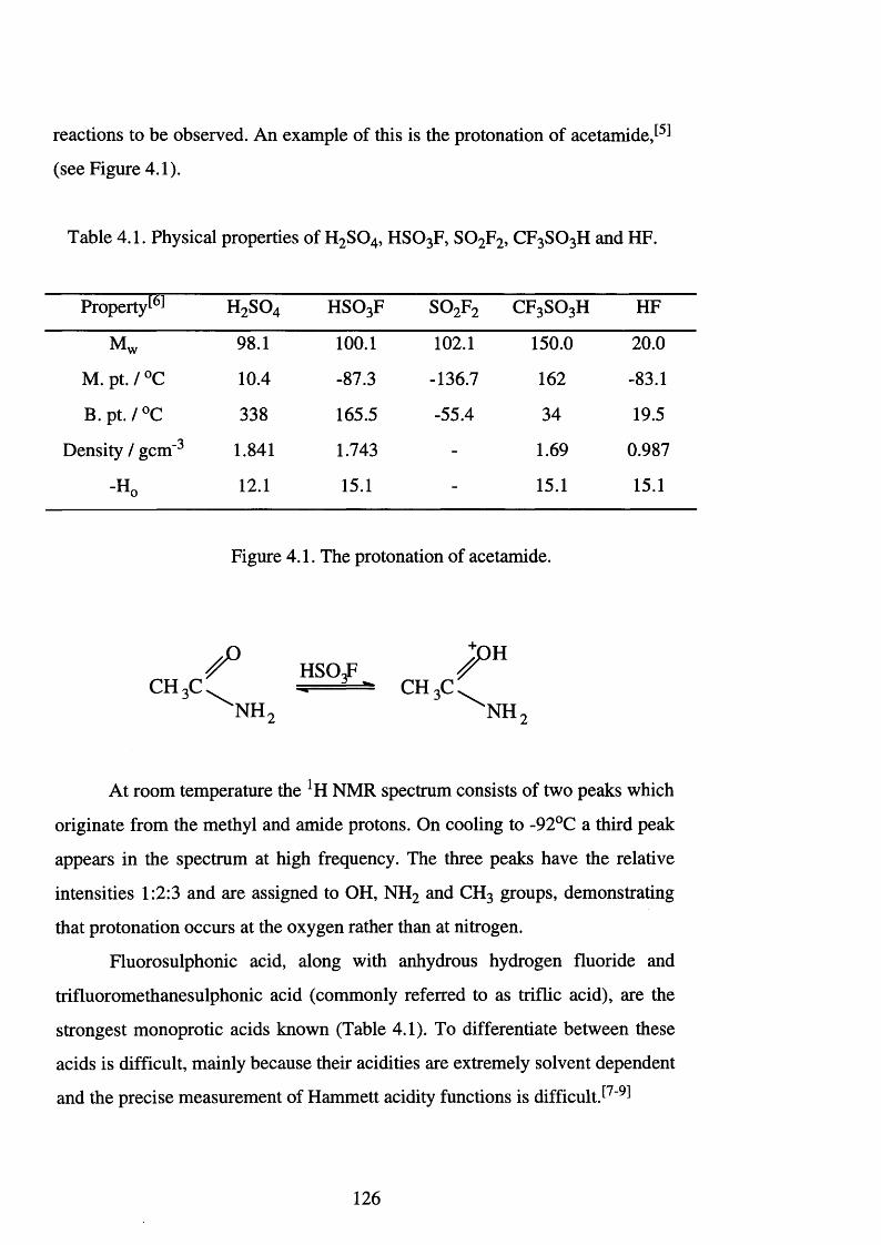
reactions to be observed. An example of this is the protonation of acetam ide,^
(see Figure 4.1).
Table 4.1. Physical properties of H2 S 0 4, HSO3 F, S 0 2 F2, CF3 SO3 H and HF.
Property^ h 2 s o 4 HSO3 F s o 2 f 2 CF3 SO3 H HF
Mw 98.1 1 0 0 . 1 1 0 2 . 1 150.0 2 0 . 0
M. pt. / °C 10.4 -87.3 -136.7 162 -83.1
B .p t ./° C 338 165.5 -55.4 34 19.5
Density / gem " 3 1.841 1.743 - 1.69 0.987
-H0 1 2 . 1 15.1 - 15.1 15.1
Figure 4.1. The protonation of acetamide.
CH3C.n h 2
At room temperature the lH NMR spectrum consists of two peaks which
originate from the methyl and amide protons. On cooling to -92°C a third peak
appears in the spectrum at high frequency. The three peaks have the relative
intensities 1:2:3 and are assigned to OH, NH2 and CH3 groups, demonstrating
that protonation occurs at the oxygen rather than at nitrogen.
Fluorosulphonic acid, along with anhydrous hydrogen fluoride and
trifluoromethanesulphonic acid (commonly referred to as triflic acid), are the
strongest monoprotic acids known (Table 4.1). To differentiate between these
acids is difficult, mainly because their acidities are extremely solvent dependent
and the precise measurement of Hammett acidity functions is difficult J7-9^
HSOgF^CH 3C
H
NH
126
Compared to hydrogen fluoride, fluorosulphonic acid and triflic acid
possess large liquid ranges and are easily purified by distillation at atmospheric
pressure. They are also compatible with glass which means synthetic
procedures and spectroscopic characterisation are straightforward. Although
fluorosulphonic acid and triflic acid share comparable physical properties,
differences in their chemical behaviour has led to a far greater use of triflic acid
in the areas of synthesis and c a t a l y s i s T r i f l i c acid and its conjugate base
possess an extremely high thermal stability and a resistance to both reductive
and oxidative cleavage. This non-oxidising behaviour minimises the number of
potential side reactions, and reduces the hazards associated with the use of
strong oxidising acids such as perchloric acid. Although triflic acid fumes in
moist air, it is completely miscible in water and many polar organic solvents.
These properties and the highly labile nature of the triflate group have resulted
in an extensive amount of literature, and this was most recently reviewed in1977 HO]
Fluorosulphonic acid undergoes an immediate and vigorous reaction
when hydrolysed and this occurs via two pathways Part of the acid
hydrolyses rapidly to HF and H2 S 0 4, the extent of which depends on the rate of
addition and the temperature. The remainder of the acid forms the hydroxonium
salt, [H3 0 ]+[S0 3 F]", which then undergoes slow hydrolysis. Woolf et alSn ̂
have prepared aqueous solutions of the almost unhydrolysed acid. They also
report that when excess water is added to fluorosulphonic acid, it does not
completely react to form HF and H2 S 0 4 but instead, a stable equilibrium is
rapidly achieved.
127
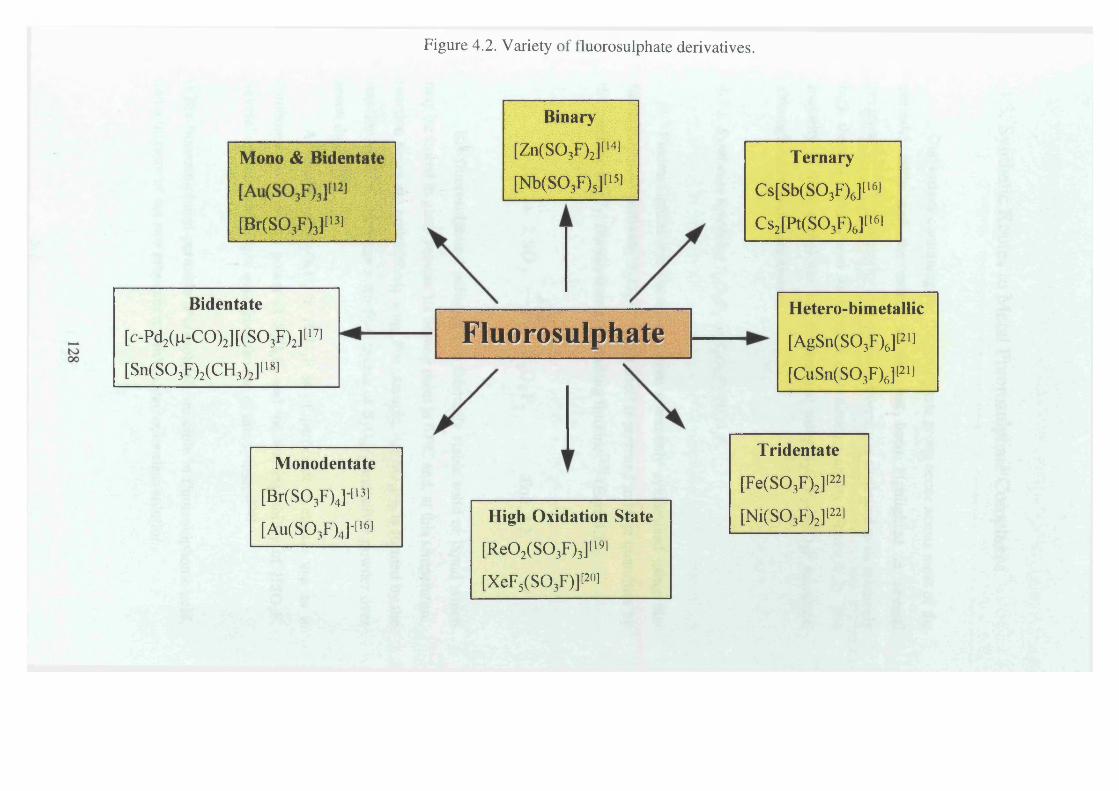
Figure 4.2. Variety of fluorosulphate derivatives.
M ono & B identateA ' ' v ’i'V -V / '
1
t V 3A /3J
[Br(S03F)3][>3]
Bidentate
[c-Pd2(n-C0)2][(S03F)2][>7]
[Sn(S03F)2(CH3)2][181
M onodentate
[Br(S03F)4]li3]
[Au(S03F)4]-[|61
Binary
[Zn(S03F)2][14!
[Nb(S03F)5]ll5)
17 l l l A V * A C 111 Vi n -
* 1 U O I..............
O S U I pna t c........
High O xidation State
[Re02(S03F)3][19l
[XeF5(S03F)]P°l
T ern a ry
Cs[Sb(S03F)6][|6)
Cs2[Pt(S03F)6]l16l
H etero-bim etallic
[AgSn(S03F)6]P>l
[CuSn(S03F)6]P»
T riden ta te
[Fe(S03F)2]P21
[Ni(S03F)2]P21
4.3. Synthetic Routes to Metal Fluorosulphate Complexes.
Derivatives containing the fluorosulphate group occur across most of the
periodic table and the extent of this has been highlighted in several
reviews.^2,3,23,24] This ability to show such diversity is attributed to its relatively
high thermal stability and its versatile co-ordinating ability (Figure 4.2). The
majority of these complexes can be prepared using S2 0 6 F2 -HS0 3F mixtures,
although other routes are known.
4.3.1. Syntheses involving S20 6F2 or S20 6F2-HS03F.
Fluorosulphate derivatives are most commonly synthesised using bis-
fluorosulphuryl peroxide, S2 0 6 F2, which itself is prepared in large quantities by
the catalytic (AgF2) fluorination of S 0 3 using fluorine[25J (Eqn. 4.2).
F2 + 2 SO 3 2 » S 20 6F2 Eqn. 4.2.
Bis-fluorosulphuryl peroxide is a thermally stable solid or liquid which
may be stored in glass vessels. Its boiling point is 67°C and, at this temperature,
reaction times are prohibitively long. For example, A g(S0 3 F ) 2 is formed by the
reaction, at 67°C, between a ten fold excess of S2 0 6 F2 and silver powder over
seven days P 4^
A mixture of S2 0 6 F2 in H S 03F is of particular synthetic use as it
combines the oxidising power of S2 0 6 F2 and the ionising ability of H S 0 3 F.
Several distinct advantages arise from the use of this sy s te m :-^
i) Bis-fluorosulphuryl peroxide is completely miscible in fluorosulphonic acid,
and a mixture of the two produces a stable, clear, colourless solution.
129
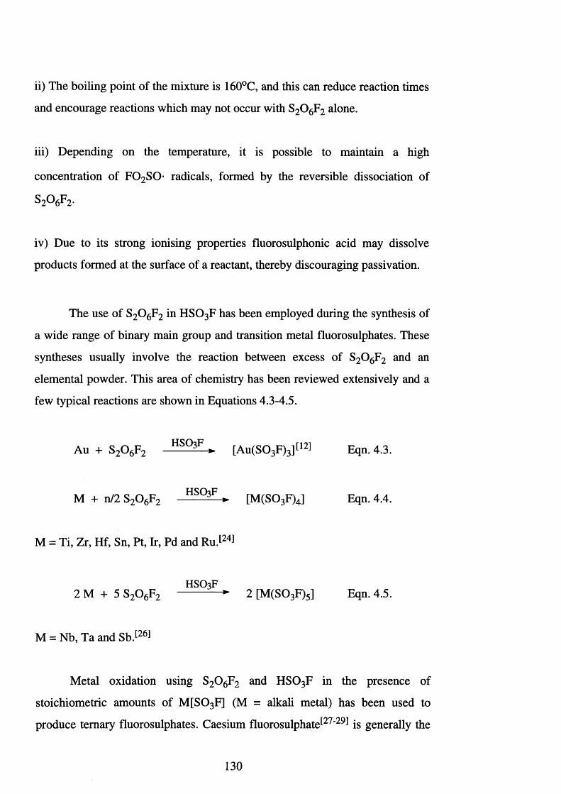
ii) The boiling point of the mixture is 160°C, and this can reduce reaction times
and encourage reactions which may not occur with S2 0 6 F2 alone.
iii) Depending on the temperature, it is possible to maintain a high
concentration of F 0 2 S0- radicals, formed by the reversible dissociation of
S2^6p2-
iv) Due to its strong ionising properties fluorosulphonic acid may dissolve
products formed at the surface of a reactant, thereby discouraging passivation.
The use of S2 0 6 F2 in HSO3 F has been employed during the synthesis of
a wide range of binary main group and transition metal fluorosulphates. These
syntheses usually involve the reaction between excess of S2 0 6 F2 and an
elemental powder. This area of chemistry has been reviewed extensively and a
few typical reactions are shown in Equations 4.3-4.5.
Au + S2 0 6 F 2 HS° 3F ► [Au(S03 F)3][12] Eqn. 4.3.
M + n/2 S2 0 6 F2 HSQ3F ► [M (S0 3 F)4] Eqn. 4.4.
M = Ti, Zr, Hf, Sn, Pt, Ir, Pd and Ru.[24]
HSO3F2 M + 5 S2 0 6 F2 ► 2 [M (S03 F)5] Eqn. 4.5.
M = Nb, Ta and Sb . [ 2 6 1
Metal oxidation using S2 0 6 F2 and H S03F in the presence of
stoichiometric amounts of M [S0 3 F] (M = alkali metal) has been used to
produce ternary fluorosulphates. Caesium fluorosulphate^27*29 ̂ is generally the
130
alkali metal fluorosulphate of choice in these reactions and there are several
reasons for this:-
i) Caesium fluorosulphate is formed in situ by the reaction of CsCl and
H S 0 3 F.[26] Hydrogen chloride, the by-product, must be removed prior to the
addition of the S2 0 6 F2, otherwise oxidation leads to derivatives of the type
[C 10J+ (jc = 1 or 2). These result in the formation of a red-orange impurity
which may interfere with the reaction.
ii) The caesium cation possesses a low reduction potential and is also the
weakest electrophile and least polarising alkali metal cation.
iii) Generally, caesium salts are highly soluble in many strong- or super-acid
systems.
iv) Unreacted C s[S0 3 F] is easily recognised by the occurrence of an infrared
absorption at 728 cm"1, assigned to the v 2 sulphur-fluorine stretch; v 2 is found
at gradually increasing wavenumbers for the other alkali metal fluorosulphates.
This may lead to an unambiguous assignment because these higher frequencies
can coincide with coordinated fluorosulphate stretches.
4.3.1.1. Limitations o f the S2O^F2-HSO^F system.
Bis-fluorosulphuryl peroxide was first isolated and characterised by
Dudley and Cady in 1957.[301 It was prepared by the fluorination of S 0 3 in a
flow reactor,*^ and was catalysed by AgF2 at 100 to 170°C. Since then, a
number of alternative routes to S2 0 6 F2 have been published and these include
the low temperature electrolysis of dilute solutions of K [S0 3 F] in
fluorosulphonic acid,^31 ̂ the reaction of CrF5 and S 0 3 in a 5:1 molar ratioJ32̂
the photolysis of C10S03F at ambient temperatures for 2-4 hoursj33̂ the
131
reaction of Cs[AgF4] with S 0 3 J 34̂ the low temperature combination of HSO3 F
and 0 2 +[AsF6 ]V 35] and finally, the reaction of F 0 S 0 2F and S 0 3 J23̂ However,
none of these methods have provided a more synthetically viable route to bis-
fluorosulphuryl peroxide than the original method.
Over the years, a number of flaws were found in the original reactor
design. Serious concerns by Cady himself led him to publish a waming^36̂
about the presence of the potentially explosive by-product fluorine
fluorosulphate, F 0 S 0 2 F. Other problems have also come to lightP 1 ̂ These
include the S 0 3 delivery system, the copper reactor which proved insufficiently
resistant to fluorine at elevated temperatures, the glass-to-metal inlet systems,
the use of asbestos and finally the lack of any disposal tower for the highly
volatile effluent gases, which included F2 and F 0 S 0 2F and present serious
hazards.
Aubke et al. have recently published details of a new but similar
catalytic reactor^37! (AgF2 on copper turnings as a support) for the fluorination
of SO3 in a flow system. The new method eliminates the hazards previously
described, but it still requires the building and construction of a large,
specialised and expensive reactor. This, in turn, means that S2 0 6 F2 is not
readily available in bulk quantities and, unless it is produced commercially,
then the number of people involved in this area of research will remain small.
A further drawback of the S2 0 6 F2 -H S03F system is the reaction
conditions and times. Table 4.2 summarises some of the reaction conditions
involved in the formation of fluorosulphate derivatives. The temperatures used
are in the region 25-150°C, while the reaction times vary from half a day to
four weeks. This highlights the fact that this route into fluorosulphate
derivatives is neither quick nor convenient.
132
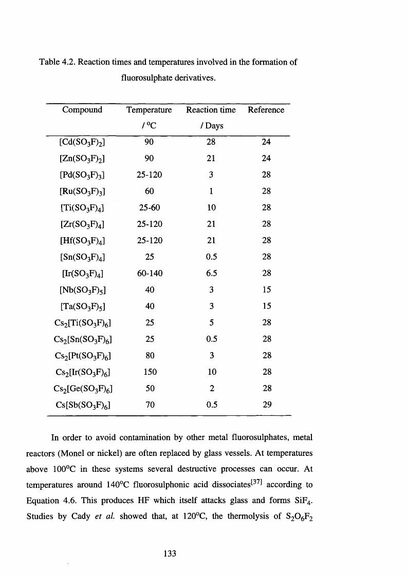
Table 4.2. Reaction times and temperatures involved in the formation of
fluorosulphate derivatives.
Compound Temperature
/°C
Reaction time
/D ays
Reference
[Cd(S0 3 F)2] 90 28 24
[Zn(S0 3 F)2] 90 2 1 24
[Pd(S0 3 F)3] 25-120 3 28
[Ru(S0 3 F)3] 60 1 28
[Ti(S0 3 F)4] 25-60 1 0 28
[Zr(S0 3 F)4] 25-120 2 1 28
[Hf(S0 3 F)4] 25-120 2 1 28
[Sn(S0 3 F)4] 25 0.5 28
[Ir(S0 3 F)4] 60-140 6.5 28
[Nb(S0 3 F)5] 40 3 15
[Ta(S0 3 F)5] 40 3 15
Cs2 [Ti(S0 3 F)6] 25 5 28
Cs2 [Sn(S0 3 F)6] 25 0.5 28
Cs2 [Pt(S0 3 F)6] 80 3 28
Cs2 [Ir(S0 3 F)6] 150 1 0 28
Cs2 [Ge(S0 3 F)6] 50 2 28
Cs[Sb(S0 3 F)6] 70 0.5 29
In order to avoid contamination by other metal fluorosulphates, metal
reactors (Monel or nickel) are often replaced by glass vessels. At temperatures
above 100°C in these systems several destructive processes can occur. At
temperatures around 140°C fluorosulphonic acid dissociates^37̂ according to
Equation 4.6. This produces HF which itself attacks glass and forms SiF4.
Studies by Cady et al. showed that, at 120°C, the thermolysis of S2 0 6 F2
133
produces O2 and S2 0 5 F2 ,t38] hence reaction vessels must be vented regularly to
avoid explosions. At certain temperatures, the catalytic decomposition of
S2 0 6 F2 to 0 2 and S2 0 5 F2 may occurJ37̂ This was observed during the
formation of Ir(S0 3 F)4. At 130°C, Ir(S0 3 F ) 4 decomposes to Ir(S0 3 F)3, S2 0 5 F2
and 0 2, the Ir(S0 3 F ) 3 is then re-oxidised by S2 0 6 F2 to form Ir(S0 3 F)4.
H S 03F HF + S 0 3 Eqn. 4.6.
The reaction of bis-fluorosulphuryl peroxide and H S 03F with a variety
of metal carbonyls and chlorides has been investigated J24 ̂ However, with
metal carbonyls, the CO is not only substituted but it is also oxidised to C 0 2
whilst, with metal chlorides, oxidation of the chlorine leads to chlorine (I) to
(VI) fluorosulphate derivatives, therefore necessitating the use of large excesses
° f s 2 o 6 f 2.
4.3.2. Displacement reactions.
In 1967, a route for preparing transition metal fluorosulphates was
required and Woolf described the preparation of bivalent fluorosulphate
derivatives of Mn, Fe, Co, Ni, Cu, Zn and CdJ39̂ Initially, copper salts were
investigated and it was found that copper (II) chloride, sulphate and acetate
undergo displacement in boiling fluorosulphonic acid to produce copper
bisfluorosulphate. Copper (II) fluoride was found to undergo incomplete
substitution, the ease of replacement following the sequence [CH3 C 0 2]‘ >
[S04]2- > Cl" > F \ The divalent fluorosulphates of Mn, Fe, Ni, Cu, Zn and Cd
were all formed in an identical manner, and the ease of replacement followed
the above sequence. More recently, the solvolysis of FeCl3 J40 ̂Zr(C 0 2 CF3)4 4̂1 ̂
and A g(C 0 2 CF3)̂ 42 ̂ in H S 03F has been shown to produce Fe(S0 3 F)3,
Z r(S 0 3 F ) 4 and A gS03F respectively. Cady et al. noted that the solvolysis of
metal chlorides in HSQ3F appeared to be facilitated by the addition of
134
K [S 0 3 F ]J 4 3 1 which may aid the removal of fluorosulphate containing products
from the surface of the reactant.
The use of S2 0 6 F2 and S2 0 5 F2 in displacement reactions does not
produce binary fluorosulphates, but leads to heteroleptic complexes such as oxo
fluorosulphates^2 4 1 (Eqn.’s 4.7 - 4.9).
TaCl5 + S2 0 6 F2 -> [TaO(S03 F)3] Eqn. 4.7.
WC16 + S2 0 6 F2 [W 0(S0 3 F)4] Eqn. 4.8.
Ti(OCH 3 ) 4 + S2 OsF2 -> [Ti(OCH3 )2 (S 0 3 F)2] Eqn. 4.9.
An alternative approach is the reaction of metal carbonyls with S2 0 6 F2
which first substitutes and is then oxidised. However, there are only three
examples of this type of reaction which appears to be restricted to the first row
transition metals (Eqn.’s 4.10 - 4.12)J2 4 1 Also as explained earlier, the use of
S2 0 6 F2 and CO is not ideal.
[Mn2 (CO)10] + S2 0 6 F2 —̂ [M n(S03 F)4] Eqn. 4.10.
Co2 (CO ) 8 + S2 0 6 F2 —» [Co(S03 F)2] Eqn. 4.11.
Cr(CO ) 6 + S2 0 6 F2 —» [Cr(S03 F)3] Eqn. 4.12.
The use of these types of displacement reactions appears to be restricted
mainly to the first row transition elements.
135
4.3.3. Syntheses involving B rS03F.
Bromine fluorosulphate, B rS0 3 F^43 ̂ has not found many applications
within synthetic chemistry, the reasons for this appear to be the excessively
long reaction times and the need for S2 0 6 F2 for its synthesis. Its limited use
includes the synthesis of the noble metal fluorosulphates [Pd(S0 3 F)2]
[Pt(S0 3 F)4] / 45 ̂ [Ag3 (S 0 3 F)4] / 46 ̂ and [Au(S03 F)3 ]J45 ̂which are prepared by
oxidation of the respective noble metal.
4.3.4. Insertion reactions.
The insertion of S 0 3 into a metal-fluorine bond has produced
fluorosulphate derivatives in a few instances (Eqn.’s 4.13-4.17). The reaction
between AgF2 and S 0 3 produces [Ag(S0 3 F)2],[42̂ and this is expected when
one considers the catalytic nature of AgF2 during the formation of S2 0 6 F2 from
S 0 3 and F2 (Section 4.3.1.1. and Eqn. 4.14). The reaction between Ag, BrF3
and S 0 3 involves the fluorination of silver followed by the insertion of S 0 3 J47 ̂
whilst the reaction between S 0 3 and CrF5, at -22°C, offers a route to
AgF2 + S 0 3 —> [Ag(S0 3 F)2] Eqn. 4.13.
[A g(S0 3 F)2] + F2 —> AgF2 + S2 0 6 F2 Eqn. 4.14.
3 Ag + 2 BrF3 + 3 S 0 3 —> 3[ A g(S0 3 F)2] + Br2 Eqn. 4.15.
WF6 + S 0 3 [WF2 (S 0 3 F)4] [48] Eqn. 4.16.
CrF5 + S 0 3 —> [Cr(S0 3 F)3] + S2 O^F2 Eqn. 4.17.
136
4.3.5. Oxidising reactions involving H S 03F.
Fluorosulphonic acid is a mild oxidising reagent Copper and bismuth
both react with the boiling acid to produce fluorosulphates derivatives, while
Ag, As and Sb all dissolve to give colourless solutions. Niobium, Ta, U and Pb
all dissolve to produce green solutions and Na, K, Ca, In, T1 and Sn react to
produce green solutions over white precipitates. Woolf et a l established that
the white precipitates are fluorosulphates or their decomposition products. They
also noted that the ESR behaviour and UV spectra of the green solutions
resembled those of sulphur in oleum. This correlates with the fact that the
metals which produced the green solutions are good reducing agents in acidic
solutions, and hence reduce the sulphur to its elemental form, whereas, the less
potent reducing metals can only reduce HSO3 F to S 0 2.
Aubke et a l have recently re-investigated the oxidation of Sb by
HSO 3 F /50! their intention being to prepare the univalent antimony salt,
Sb(S0 3 F). An earlier communication had reported the formation and isolation
of this sa lt/51! however, no spectroscopic or analytical data has been published.
Aubke’s attempt to isolate the antimony (I) fluorosulphate salt failed, and no
univalent antimony compounds were identified. However, they were able to
structurally characterise some previously unknown antimony (III) fluoro-
fluorosulphate compounds.
4.4. Decomposition of Fluorosulphates.
The decomposition of fluorosulphate derivatives is observed to occur via
four different pathways, and is outlined as follows:-
i) The elimination o f sulphur trioxide. The oxidation of niobium metal using
S2 0 6 F2, in HSO 3 F results in the formation of the unstable pentafluorosulphate,
137
[Nb(S0 3 F)5], this loses S 0 3 and eventually forms the solid [NbF2 (S 0 3 F)3]^15̂
(Eqn. 4.18).
N b(S0 3 F ) 5 ^ N bF(S0 3 F ) 4 + S 0 3 NbF2 (S 0 3 F ) 3 + S 0 3 Eqn. 4.18.
ii) The elimination o f S20 5F2. This results in the formation of an oxo-
fluorosulphate complex. As noted earlier, substitution reactions between metal
chlorides or carbonyls and S2 0 6 F2 usually produces an oxo-fluorosulphate as
the p ro d u c t^ (Eqn.’s 4.19 and 4.20).
WC16 + S2 0 6 F2 -» [W 0(S 0 3 F)4] + S2 0 5 F2 Eqn. 4.19.
W(CO ) 6 + S2 0 6 F2 ^ [W 0(S 0 3 F)4] + S2 0 5 F2 Eqn. 4.20.
Further examples of this type of reactivity include the formation of
[V 0 (S 0 3 F)3], [N b0(S 0 3 F)3], [M o0 2 (S 0 3 F)2] and [Re0 2 (S 0 3 F)3].[24] The
elimination of S2 0 5 F2 does not always result exclusively in the formation of an
oxo-fluorosulphate complex. For example, the decomposition of Ir(S0 3 F ) 4
yields S2 0 5 F2, but Ir(S0 3 F ) 3 and 0 2 are also produced.^37!
iii) The reductive elimination o f SO3F radicals. The thermal decomposition of
Pdn [PdIV(S 0 3 F)6] leads to the elimination of S2 0 6 F2 (Eqn. 4.21).[52] This is
not common and highlights the strong oxidising ability of the palladium
fluorosulphate complex. The addition of bromine to the mixture accelerates the
rate of decomposition which produces Pd(S0 3 F ) 2 and B rS0 3 F. A similar
process was observed for A g(S0 3 F ) 2 which decomposes at 210°C to produce
A g(S0 3 F) and S2 0 6 F2.[53]
o
Pdu [PdIV(S 0 3 F)6] 2 Pd(S0 3 F ) 2 + S2 OeF2 Eqn. 4.21.
138
iv) The decomposition of alkaline and alkaline earth metal fluorosulphate salts,
follows one or both of the paths outlined in Equations 4.22 and 4.23.
M (S0 3 F)x —) MFjp + x SO3 Eqn. 4.22.
2 M (S 0 3 F)a; —̂ + x SO2 F2 Eqn. 4.23.
The actual decomposition generally reflects small differences in the
structure, for example the co-ordination number for Ca(II) and Ba(II) is six and
eight respectively. However, the polarising power of Ba(II) is lower than that of
Ca(II). Consequently, C a(S0 3 F ) 2 is pyrolysed to CaF2 whereas Ba(S0 3 F ) 2
produces B a(S04). These types of decomposition reactions have been studied
extensively by Muetteries et alS54,55^
4.5. Spectroscopic Characterisation of Fluorosulphate
Compounds.
4.5.1. Vibrational spectroscopy.
Vibrational spectroscopy is a powerful tool for the identification of
fluorosulphate derivatives. The most useful information is found in the region
1500 - 700 cm '1, and reveals the type of interaction between the cation and
anion, as well as the mode of coordination of the fluorosulphate ion (Figure
4.3).
139
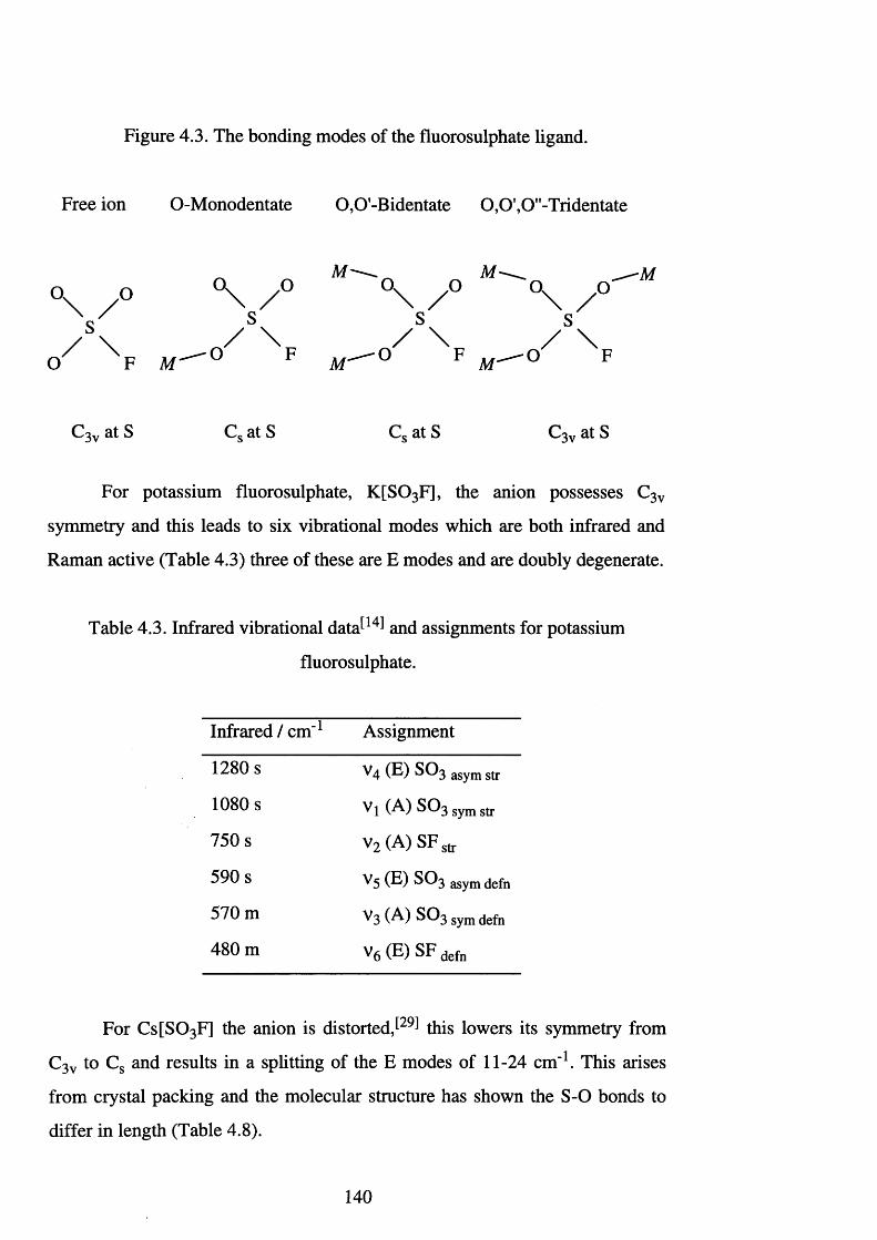
Figure 4.3. The bonding modes of the fluorosulphate ligand.
Free ion O-Monodentate 0,0'-Bidentate 0 ,0 ’,0"-Tridentate
_ M ' — . ___ __Q ° \ / > 0 ^ 0 / 0
o/S\ ^A ,C3vatS Cs atS Cs atS C3vatS
For potassium fluorosulphate, K [S0 3 F], the anion possesses C3v
symmetry and this leads to six vibrational modes which are both infrared and
Raman active (Table 4.3) three of these are E modes and are doubly degenerate.
Table 4.3. Infrared vibrational d a t a ^ and assignments for potassium
fluorosulphate.
Infrared / cm - 1 Assignment
1280 s v 4 (E) S03 asym str
1080 s Vl (A) S°3symstr
750 s v2 (A) SFstr
590 s ^ 5 (E) S03 asym defn
570 m ^3 (A) S03 Sym defn
480 m V6 (E) SF defn
For C s[S0 3 F] the anion is d i s t o r t e d t h i s lowers its symmetry from
C3v to Cs and results in a splitting of the E modes of 11-24 cm-1. This arises
from crystal packing and the molecular structure has shown the S -0 bonds to
differ in length (Table 4.8).
140
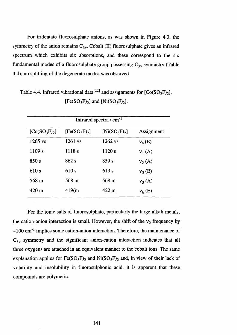
For tridentate fluorosulphate anions, as was shown in Figure 4.3, the
symmetry of the anion remains C3v. Cobalt (II) fluorosulphate gives an infrared
spectrum which exhibits six absorptions, and these correspond to the six
fundamental modes of a fluorosulphate group possessing C3v symmetry (Table
4.4); no splitting of the degenerate modes was observed
Table 4.4. Infrared vibrational d a t a ^ and assignments for [Co(S0 3 F)2],
[Fe(S0 3 F)2] and [Ni(SQ3 F)2].
Infrared spectra / cm" 1
[Co(S0 3 F)2] [Fe(S0 3 F)2] [Ni(S0 3 F)2] Assignment
1265 vs 1261 vs 1262 vs v4 (E)
1109 s 1118s 1 1 2 0 s Vi (A)
850 s 862 s 859 s v 2 (A)
610 s 610 s 619 s v5 (E)
568 m 568 m 568 m v 3 (A)
420 m 419(m 422 m v6 (E)
For the ionic salts of fluorosulphate, particularly the large alkali metals,
the cation-anion interaction is small. However, the shift of the v 2 frequency by
~100 cm ' 1 implies some cation-anion interaction. Therefore, the maintenance of
C3v symmetry and the significant anion-cation interaction indicates that all
three oxygens are attached in an equivalent manner to the cobalt ions. The same
explanation applies for Fe(S0 3 F ) 2 and N i(S0 3 F ) 2 and, in view of their lack of
volatility and insolubility in fluorosulphonic acid, it is apparent that these
compounds are polymeric.
141
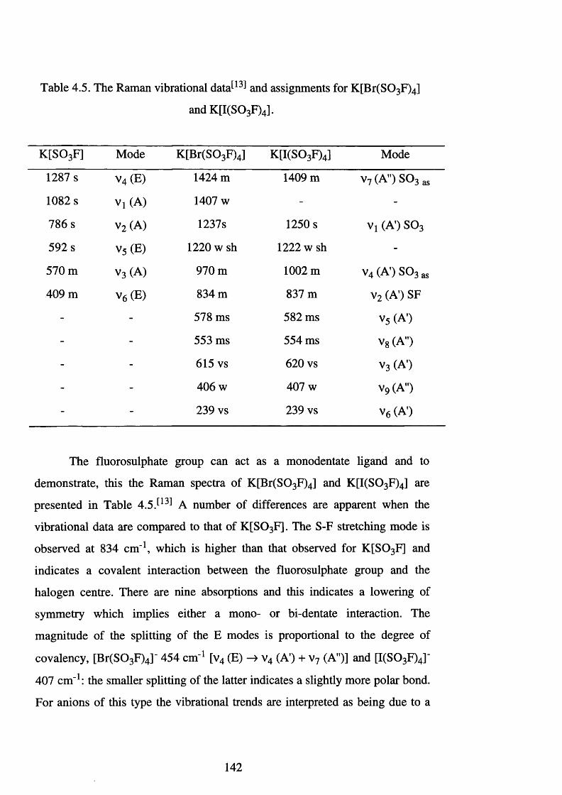
Table 4.5. The Raman vibrational data^1̂ and assignments for K[Br(S0 3 F)4]
and K[I(S0 3 F)4].
K[S03F] Mode K[Br(S03F)4] K[I(S03F)4] Mode
1287 s v4 (E) 1424 m 1409 m v7 (A") S03 as
1082 s Vj (A) 1407 w - -
786 s v2 (A) 1237s 1250 s Vi (A1) S03
592 s v5 (E) 1 2 2 0 w sh 1 2 2 2 w sh -
570 m V3 (A) 970 m 1 0 0 2 m v4(A') S03as
409 m V6 (E) 834 m 837 m v2 (A') SF- - 578 ms 582 ms V5 (A')- - 553 ms 554 ms v8 (A")- - 615 vs 620 vs V3 (A’)- - 406 w 407 w V9 (A")
- - 239 vs 239 vs V6 (A')
The fluorosulphate group can act as a monodentate ligand and to
demonstrate, this the Raman spectra of K[Br(S0 3 F)4] and K [I(S0 3 F)4] are
presented in Table 4.5 A number of differences are apparent when the
vibrational data are compared to that of K [S0 3 F]. The S-F stretching mode is
observed at 834 cm '1, which is higher than that observed for K [S0 3 F] and
indicates a covalent interaction between the fluorosulphate group and the
halogen centre. There are nine absorptions and this indicates a lowering of
symmetry which implies either a mono- or bi-dentate interaction. The
magnitude of the splitting of the E modes is proportional to the degree of
covalency, [Br(S0 3 F)4]- 454 cm" 1 [v4 (E) v4 (A') + v 7 (A")] and [I(S0 3 F)4]'
407 cm '1: the smaller splitting of the latter indicates a slightly more polar bond.
For anions of this type the vibrational trends are interpreted as being due to a
142
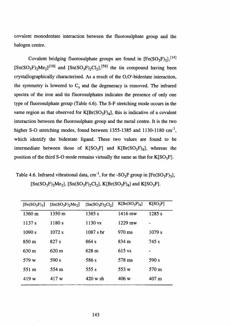
covalent monodentate interaction between the fluorosulphate group and the
halogen centre.
Covalent bridging fluorosulphate groups are found in [Fe(S0 3 F)3]
[Sn(S0 3 F)2 Me2] ^ and [Sn(S0 3 F)2 Cl2 ]J56 ̂ the tin compound having been
crystallographically characterised. As a result of the 0 ,0-bidentate interaction,
the symmetry is lowered to Cs and the degeneracy is removed. The infrared
spectra of the iron and tin fluorosulphates indicates the presence of only one
type of fluorosulphate group (Table 4.6). The S-F stretching mode occurs in the
same region as that observed for K[Br(S0 3 F)4], this is indicative of a covalent
interaction between the fluorosulphate group and the metal centre. It is the two
higher S-O stretching modes, found between 1355-1385 and 1130-1180 cm '1,
which identify the bidentate ligand. These two values are found to be
intermediate between those of K [S0 3 F] and K[Br(S0 3 F)4], whereas the
position of the third S-O mode remains virtually the same as that for K [S0 3 F].
Table 4.6. Infrared vibrational data, cm '1, for the -S 03F group in [Fe(S0 3 F)3],
[Sn(S0 3 F)2 Me2], [Sn(S0 3 F)2 Cl2], K[Br(S0 3 F)4] and K [S0 3 F].
[Fe(S03F)3] [Sn(S03F)2Me2] [Sn(S03F)2Cl2] K[Br(S03F)4] K[S03F]
1360 m 1350 m 1385 s 1416 mw 1285 s
1137 s 1180 s 1130 vs 1229 mw -
1090 s 1072 s 1087 s br 970 ms 1079 s
850 m 827 s 864 s 834 m 745 s
630 m 620 m 628 m 615 vs -
579 w 590 s 586 s 578 ms 590 s
551 m 554 m 555 s 553 w 570 m
419 w 417 w 420 w sh 406 w 407 m
143
Bridging and terminal fluorosulphate groups may be present in the same
molecule. This is the case for [Br(S03 F)3],[13) [I(S0 3 F)3] [13] and
[Sn(S0 3 F)4] J ' The infrared spectra are very complex and in the case of
B r(S0 3 F ) 3 a total of 27 bands and shoulders are observed between 1500-200
cm"1. Considering just the v(S-O) region, 1500-900 cm '1, one set of absorptions
are in approximately the same place as those in [Br(S03 F)4]', and the second
set are assigned to bridging fluorosulphate groups. The presence of bridging
fluorosulphate groups leads to low volatility, high decomposition temperatures
and a reluctance to dissolve in H S 0 3 F, as is the case for [Sn(S0 3 F)4] and
B r(S0 3 F)3.
Finally, weakly coordinating highly ionic fluorosulphate groups have
been observed for [M (S0 3 F)2 (C 0)2][57] (M = Pt or Pd), [M (S0 3 F)(C0)5] [19]
(M = Mn or Re) and [Sn(S0 3 F)2] For example, the vibrational data for
[Re(S0 3 F)(C0)5] ̂ 1 9 1 is consistent with a weakly coordinating monodentate
fluorosulphate group. Several important features highlight this (Table 4.7). i) In
the S-O and S-F stretching region, the S-F stretch and the symmetric S-O
stretch for ionic fluorosulphates are found in nearly identical regions (e.g.
K [S 0 3 F] v(S-F) = 745 and v(S-O) = 1079 cm '1), ii) The splitting of the
asymmetric S 0 3 stretch, which is indicative of a departure from C3v symmetry,
is only slight (-60 cm " 1 for Re) and this splitting is too large to be solely due to
site affects (for example in [NO][S0 3 F] site effects result in a splitting of 10-
20 cm_1 )J58 ̂ iii) The position of v(SO—M), 1030 cm"1, is consistent with the
highly ionic character proposed for the M -OS02F interaction, iv) The position
of v(CO), 2160-1980 cm"1, is also indicative of the highly ionic nature of
-S 0 3F (for example see rhenium pentacarbonyl seflate, Table 2.14). The
spectral features described here differ markedly from the patterns displayed by
other covalent monodentate fluorosulphate groups (e.g. K[Br(S0 3 F)4], Table
4.5).
144
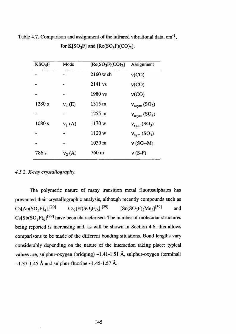
Table 4.7. Comparison and assignment of the infrared vibrational data, cm '1,
for K [S0 3 F] and [Re(S0 3 F)(CO)5].
k s o 3f Mode [Re(S03 F)(C0)2] Assignment
- - 2160 w sh v(CO)
- - 2141 vs v(CO)
- - 1980 vs v(CO)
1280 s v4 (E) 1315 m V a s y m ( S 0 2 )
- - 1255 m V a s y m ( S 0 3 )
1080 s V , (A) 1170 w V Sy m ( S 0 3 )
- - 1 1 2 0 w V s y m ( S O s )
- - 1030 m V ( S O - - M )
786 s v2 (A) 760 m v (S-F)
4.5.2. X-ray crystallography.
The polymeric nature of many transition metal fluorosulphates has
prevented their crystallographic analysis, although recently compounds such as
Cs[A u(S0 3 F)4],[29) Cs2 [Pt(S0 3 F)6],|29) [Sn(S0 3 F)2 Me2][59] and
Cs[Sb(S0 3 F)6 ]t29l have been characterised. The number of molecular structures
being reported is increasing and, as will be shown in Section 4.6, this allows
comparisons to be made of the different bonding situations. Bond lengths vary
considerably depending on the nature of the interaction talcing place; typical
values are, sulphur-oxygen (bridging) -1.41-1.51 A, sulphur-oxygen (terminal)
-1.37-1.45 A and sulphur-fluorine -1.45-1.57 A.
145
4.5.3. Fluorine-19 NMR spectroscopy.
The resonances generated by a fluorine bonded to the sulphur of a
fluorosulphate group appears to be of little use as a diagnostic tool. Although
shifts have been observed, they are usually small and the lack of multiplicity
offers no additional information. Very few fluorine shifts appear in the
literature and those reported are shifted little from that of fluorosulphonic acid.
The largest shifts (5compiex-§Hso3F) are undoubtedly those which arise
from covalently bound fluorosulphate groups. Hohorst and Shreeve conducted
19F NMR studies on a range of fluorosulphate derivatives The majority of
shifts were observed in the range -40 to -50 ppm, however, they were unable to
relate the observed shifts to any single factor.
4.5.4. Mdssbauer spectroscopy.
Mossbauer spectroscopy is a useful structural tool which can be used to
define oxidation states and local symmetry, however, it is limited to a few
nuclei such as 57Fe and 1 1 9 Sn. Mossbauer spectroscopy has successfully been
used to define the geometry in a number of tin (II) and (IV) fluorosulphate
compounds . 1 5 6 ’6 1 ' 6 3 1
4.5.5. Magnetic studies and electronic spectroscopy.
The difficulty in obtaining single crystals and the limitations of other
spectroscopic tools has meant that the characterisation of new complexes has
depended heavily on vibrational spectroscopy. Magnetic susceptibility
measurements and electronic spectroscopy have, consequently, played an
important role in the understanding of the nature of metal fluorosulphate
derivatives J64,65 ̂ The use of electronic spectroscopy and magnetic
susceptibility enabled chemists to understand more about the bonding occurring
146
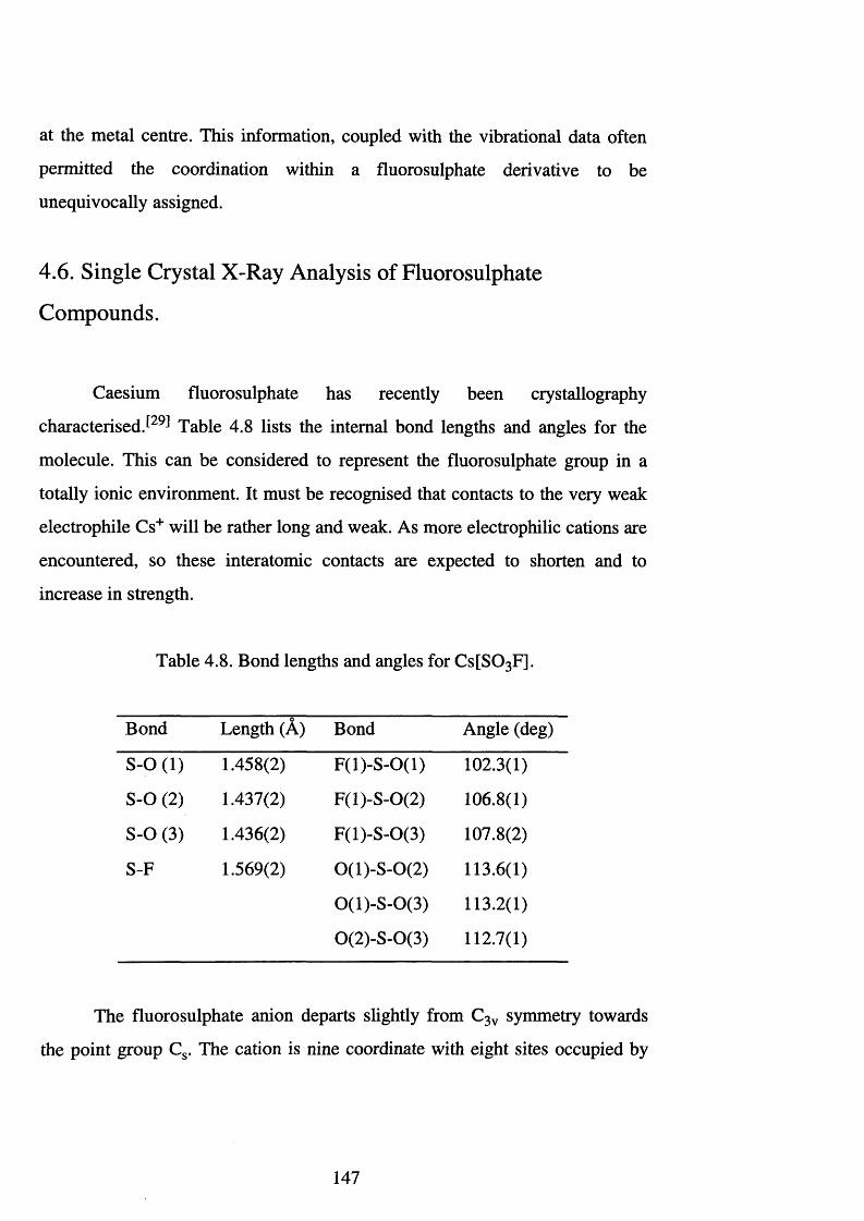
at the metal centre. This information, coupled with the vibrational data often
permitted the coordination within a fluorosulphate derivative to be
unequivocally assigned.
4.6. Single Crystal X-Ray Analysis of Fluorosulphate
Compounds.
Caesium fluorosulphate has recently been crystallography
c h a r a c t e r i s e d T a b l e 4.8 lists the internal bond lengths and angles for the
molecule. This can be considered to represent the fluorosulphate group in a
totally ionic environment. It must be recognised that contacts to the very weak
electrophile Cs+ will be rather long and weak. As more electrophilic cations are
encountered, so these interatomic contacts are expected to shorten and to
increase in strength.
Table 4.8. Bond lengths and angles for C s[S0 3 F].
Bond Length (A) Bond Angle (deg)
S-O (1) 1.458(2) F(l)-S-0(1) 102.3(1)
S-O (2) 1.437(2) F(l)-S-0(2) 106.8(1)
S-O (3) 1.436(2) F(l)-S-0(3) 107.8(2)
S-F 1.569(2) 0(l)-S -0 (2) 113.6(1)
0(l)-S -0 (3) 113.2(1)
0(2)-S-0(3) 112.7(1)
The fluorosulphate anion departs slightly from C3v symmetry towards
the point group Cs. The cation is nine coordinate with eight sites occupied by
147
oxygen and one by fluorine. The above bond parameters are comparable with
those obtained for K [S0 3 F] and [NH4 ][S 0 3 F].
The addition of fluorosulphonic acid to C s[S0 3 F] results in the
formation of a monosolvate of the composition Cs[H(S0 3 F)2]. The presence of
a rather short O—H—O hydrogen bond was confirmed by X-ray studies, and the
hydrogen atom was located. The hydrogen atom was found at the inversion
centre and the O—H—O bond was linear and symmetrical. The 0--H bond for
[H(S0 3 F)2]- is 1 .2 1 0 (2 ) A, which is rather short when compared to
[H(OTeF5 )2 r , 1.297(8) A, is still considerably longer than that for [HF2]'
which contains the strongest and shortest hydrogen bond, 1.13(1) A.
It was noted by Aubke et a l that the formation of a hydrogen bond
resulted in several changes The S-O bonds involved in hydrogen bonding
were lengthened to 1.471(2) A whereas the remaining S-O, 1.399(3) and
1.406(2) A, and S-F bonds, 1.531(2) A, were shortened relative to Cs[S0 3 F]. It
appears that bonding to the peripheral oxygen and fluorine atoms in the pair
[S 0 3 F]' and [H (S0 3 F)2]" strengthens for the binuclear species at the expense of
the bond strength in the bridging region. The coordination number of the
caesium in this species is 1 2 , and it appears that the contacts are slightly longer
than those for C s[S0 3 F]. Overall, the bonds involving peripheral atoms
strengthen slightly from C s[S0 3 F] to Cs[H(S0 3 F)2], therefore, the basicity of
the peripheral atoms decreases. Hence, the ability of these atoms to coordinate
to Cs+ is reduced and the fluorosulphate ions appear to be more nucleophilic.
The trends described above are demonstrated by the molecules
Cs[A u(S0 3 F)4] and Cs[Sb(S0 3 F)6] (Table 4.9 and Figure 4.4) where the
coordination geometries of the central atoms are square planar and octahedral
respectively. The strength of the cation-fluorosulphate interaction is reflected
by the strong bonds between the central cation and the oxygen bridging atoms,
Ob. Due to variations in the atomic number and oxidation state, the M-Ob bond
distances are not strictly comparable. Strong coordination of the fluorosulphate
groups, via oxygen, to the central ion has two, indirect, secondary effects:-^29̂ i)
148
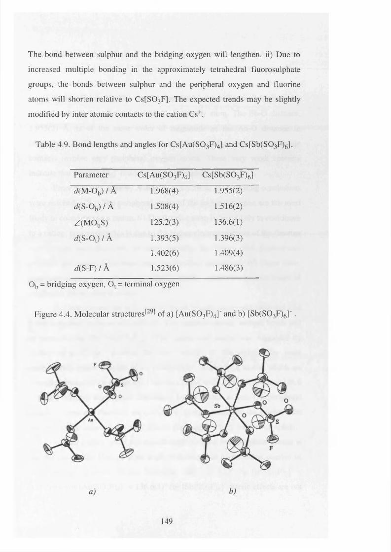
The bond between sulphur and the bridging oxygen will lengthen, ii) Due to
increased multiple bonding in the approximately tetrahedral fluorosulphate
groups, the bonds between sulphur and the peripheral oxygen and fluorine
atoms will shorten relative to Cs[S03F]. The expected trends may be slightly
modified by inter atomic contacts to the cation Cs+.
Table 4.9. Bond lengths and angles for Cs[Au(S03F)4] and Cs[Sb(S03F)6].
Parameter Cs[Au(S03F)4] Cs[Sb(S03F)6]
</(M-Ob) / A 1.968(4) 1.955(2)
d(S-Ob) / A 1.508(4) 1.516(2)
Z(M ObS) 125.2(3) 136.6(1)
d{ S-Ot) / A 1.393(5) 1.396(3)
1.402(6) 1.409(4)
d( S -F )/ A 1.523(6) 1.486(3)
Ob = bridging oxygen, Ot = terminal oxygen
Figure 4.4. Molecular structures1̂ of a) [Au(S03F)4]" and b) [Sb(S03F)6] ' .
149
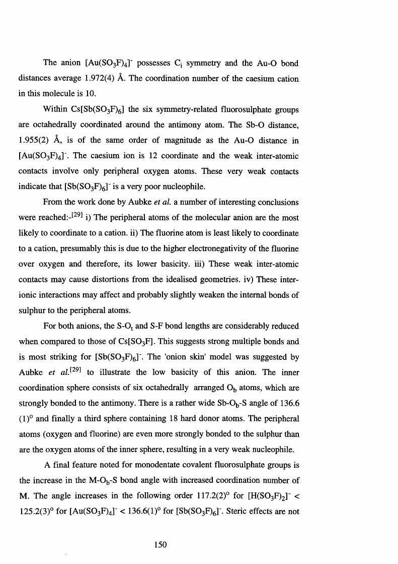
The anion [Au(S0 3 F)4]" possesses Q symmetry and the Au-O bond
distances average 1.972(4) A. The coordination number of the caesium cation
in this molecule is 1 0 .
Within Cs[Sb(S0 3 F)6] the six symmetry-related fluorosulphate groups
are octahedrally coordinated around the antimony atom. The Sb-O distance,
1.955(2) A, is of the same order of magnitude as the A u-0 distance in
[Au(S0 3 F)4] \ The caesium ion is 12 coordinate and the weak inter-atomic
contacts involve only peripheral oxygen atoms. These very weak contacts
indicate that [Sb(S0 3 F)6]‘ is a very poor nucleophile.
From the work done by Aubke et a l a number of interesting conclusions
were re a c h e d :-^ i) The peripheral atoms of the molecular anion are the most
likely to coordinate to a cation, ii) The fluorine atom is least likely to coordinate
to a cation, presumably this is due to the higher electronegativity of the fluorine
over oxygen and therefore, its lower basicity, iii) These weak inter-atomic
contacts may cause distortions from the idealised geometries, iv) These inter
ionic interactions may affect and probably slightly weaken the internal bonds of
sulphur to the peripheral atoms.
For both anions, the S-Ot and S-F bond lengths are considerably reduced
when compared to those of C s[S0 3 F]. This suggests strong multiple bonds and
is most striking for [Sb(S0 3 F)6]". The 'onion skin' model was suggested by
Aubke et alS29 ̂ to illustrate the low basicity of this anion. The inner
coordination sphere consists of six octahedrally arranged Ob atoms, which are
strongly bonded to the antimony. There is a rather wide Sb-Ob-S angle of 136.6
(1)° and finally a third sphere containing 18 hard donor atoms. The peripheral
atoms (oxygen and fluorine) are even more strongly bonded to the sulphur than
are the oxygen atoms of the inner sphere, resulting in a very weak nucleophile.
A final feature noted for monodentate covalent fluorosulphate groups is
the increase in the M-Ob-S bond angle with increased coordination number of
M. The angle increases in the following order 117.2(2)° for [H(S03 F)2]" <
125.2(3)° for [Au(S0 3 F)4]‘ < 136.6(1)° for [Sb(S0 3 F)6]-. Steric effects are not
150
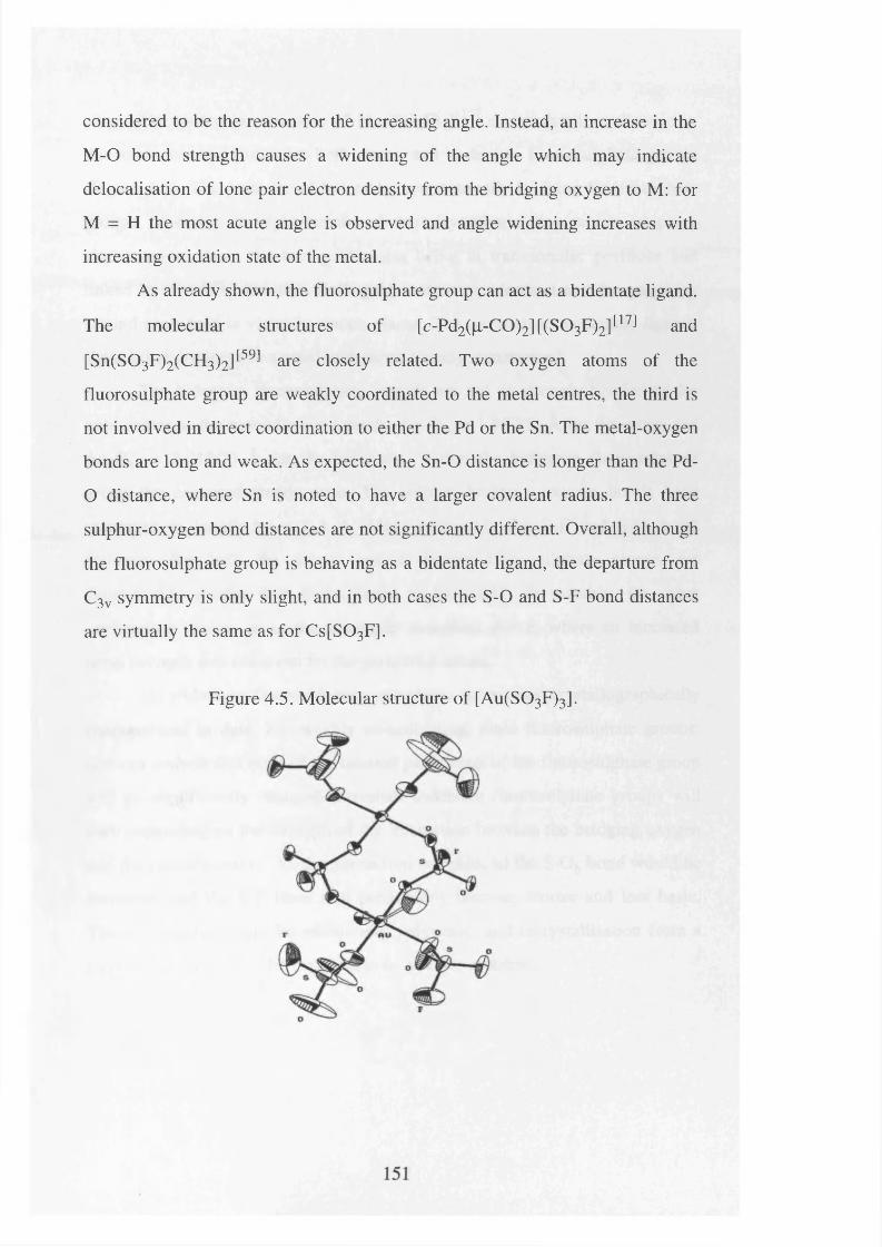
considered to be the reason for the increasing angle. Instead, an increase in the
M-O bond strength causes a widening of the angle which may indicate
delocalisation of lone pair electron density from the bridging oxygen to M: for
M = H the most acute angle is observed and angle widening increases with
increasing oxidation state of the metal.
As already shown, the fluorosulphate group can act as a bidentate ligand.
The molecular structures of [c-Pd2(|i-C0)2][(S03F)2]t17l and
[Sn(S03F)2(CH3)2]t59] are closely related. Two oxygen atoms of the
fluorosulphate group are weakly coordinated to the metal centres, the third is
not involved in direct coordination to either the Pd or the Sn. The metal-oxygen
bonds are long and weak. As expected, the Sn-O distance is longer than the Pd-
O distance, where Sn is noted to have a larger covalent radius. The three
sulphur-oxygen bond distances are not significantly different. Overall, although
the fluorosulphate group is behaving as a bidentate ligand, the departure from
C3v symmetry is only slight, and in both cases the S-O and S-F bond distances
are virtually the same as for C s[S03F].
Figure 4.5. Molecular structure of [Au(S03F)3].
The molecular structure of [Au(S0 3 F)3][12] shows that it is dimeric in
the solid-state and possesses both mono- and bi-dentate fluorosulphate groups
(Figure 4.5). The presence of bidentate, symmetrically bridging fluorosulphate
groups generates an eight-membered centrosymmetric ring which adopts a
chair conformation, the two gold atoms being in transannular positions and
linked by two S 0 2 moieties. Both gold centres are identical and the geometry
around each gold is virtually square planar. The covalent monodentate ligands
show bond distances in accord with those already summarised.
The bidentate fluorosulphate ligands are not as strongly bonded to the
gold centre as the monodentate ligands: Au-Oav = 1.957(8) A for the mono and
Au-Oav = 2.018(7) A for the bidentate. Within the bidentate fluorosulphate
group the expected trends arise. The sulphur bridging oxygen bonds have
increased in length by ~ 0.3 A. More noticeably the S-F and S-Ot bond
distances for both the mono- and bi-dentate fluorosulphate groups are
considerably shorter than those found in C s[S0 3 F]. Presumably, the same
explanation applies as in the structures described above, where an increased
bond strength was observed for the peripheral atoms.
No tridentate fluorosulphate complexes have been crystallographically
characterised to date. For weakly co-ordinating, ionic fluorosulphate groups,
one can assume that none of the internal parameters of the fluorosulphate group
will be significantly changed. Covalent tridentate fluorosulphate groups will
vary depending on the strength of the interaction between the bridging oxygen
and the cationic centre. As the interaction increases so the S-Ob bond would be
increased and the S-F bond will presumably become shorter and less basic.
These compounds will be extensively polymeric, and recrystallisation from a
suitable solvent would be expected to be a major problem.
152
4.7. Recent developments in fluorosulphate chemistry.
4.7.1 Cationic carbonyl metal species.
Very recently a number of noble metal carbonyl cations, which are
stabilised by fluorosulphate ligands,^66̂ have been reported. Little is known
about why some of these compounds have relatively high thermal stabilities
despite the absence, or near absence, of metal-carbon 7t back-bonding.
The strength of a CO bond is readily determined by vibrational
s p e c t r o s c o p y T h e carbon-oxygen stretching frequency is very sensitive to
changes in the CO bond order, caused by n back-donation from the metal into
C-O n* antibonding orbitals. Shifts to lower frequency, that observed for
gaseous carbon monoxide is 2143 cm-1, are used not only to detect and estimate
the extent of synergic bonding, but also to assign co-ordination modes of the
carbonyl ligand. Terminal monodentate CO groups are usually found in the
region 2125-1850 cm '1, while bridging bidentate CO groups have u(CO) values
between 1860-1700 cm '1.
Another group of carbonyl derivatives exists, in which n back-bonding
seems to be insignificant in the formation of a metal-carbon bond. The best
known examples include metal carbonyl cations and metal carbonyl halides.
Metal carbonyl cations have only been discovered recently whereas metal
carbonyl halides have a much longer history which stretches back to 1868 when
Schtitzenberger discovered the three platinum (II) carbonyl halides [Pt
Cl2 (CO)2], [Pt2 Cl4 (CO)2] and [Pt2 Cl4 (CO ) 3 ] . 1 6 8 1
The study of noble metal carbonyl cations began with the isolation of
carbonyl gold (I) fluorosulphate, [Au(S03 F)(C0)] J69̂ This was serendipitous
and stemmed from investigations to detect the formyl cation, [HCO]+. Attempts
to observe the cation by NMR spectroscopy using 1 3 C-enriched CO in a
superacid solution were unsuccessful. This was presumably due to proton
153
exchange which occurred even at low temperatures. It appears that the
stretching force constant of t)(CO) for [HCO]+ may represent the upper limit
for a complex ion with a solely a bonded CO: complete absence of n back-
donation. The value obtained may have acted as a benchmark for judging the
extent of n back-donation in other complexes.
Gold trisfluorosulphate was first reported in 1972 by Johnson, Dev and
Cady and it was soon realised that A u(S0 3 F ) 3 should act as a fluorosulphate
ion acceptor J 7 0 1 Later, it was shown that A u(S0 3 F ) 3 does indeed behave as a
Lewis acid in fluorosulphonic acid to form the conjugate base [Au(S0 3 F)4 ] 'J 7 1 1
In 1990 an attempt to protonate carbon monoxide using the superacid
system H S 0 3 F-A u(S0 3 F ) 3 resulted in the discovery of the metal carbonyl
cation [Au(CO)2 ]+J 6 9 1 Gaseous carbon monoxide is found to be virtually
insoluble in fluorosulphonic acid, therefore the uptake of the gas could be
easily monitored. A colour change was observed for the reaction and the
volatile reduction products, C 0 2 and S2 0 5 F2, were isolated.
Work-up yields a white moisture-sensitive solid which is stable up to
190°C and has a melting point of 49-50°C. Characterisation of the solid, using
vibrational spectroscopy, identified it as [Au(S03 F)(C0)] and the reported
v(CO) is 2195 cm-1, well above that for free CO (2143 cm '1).
It was suggested that the reductive carbonylation of A u(S0 3 F ) 3 follows
Equation 4.24. The resultant Au (I) species is then stabilised by the
complexation of CO according to Equation 4.25, the final product
[A u(S0 3 F)(C0)] results from a very facile substitution reaction as summarised
in Equation 4.26.
A u(S 0 3 F ) 3 + CO —> Au+ + C 0 2 + [S0 3 F] + S2 O^F5 Eqn. 4.24.
Au+ + 2 CO -> [Au(CO)2]+ Eqn. 4.25.
154
[Au(CO)2]+ + [SO3F]- -> [Au(S03F)(C0)] + CO Eqn. 4.26.
The need for a strong protonic acid during the synthesis of transition
metal carbonyl derivatives is apparent. The extension of this to other systems
such as H S 0 3 F-[Pt(S0 3 F)4] ̂ was soon undertaken,^13,68̂ and led to the
complexes [cis-Pt(S 0 3 F)2 (C 0)2] and [cw-Pd(S03 F)2 (C 0)2].[73] The latter
compound was structurally characterised by X-ray diffraction^74 ̂ and the
molecular structure showed a square planar geometry at the Pd centre, with
terminally bound CO and monodentate fluorosulphate groups in a cis
arrangement. The absence of significant Pd to CO 7t-back donation is
highlighted by the high CO-stretching frequencies, vav(CO) of 2218 cm-1. The
CO bond lengths are also short, 1.106(6) and 1.114(6) A, when compared to
those of gaseous carbon monoxide (cf. 1.12822 A). The X-ray study also
revealed a number of intra- and inter-molecular contacts between the carbon
atom of the CO group and the oxygens of the fluorosulphate groups, these
appear to stabilise the structure.
This synthetic approach has been extended to iridiumJ37̂ As was
described earlier, Ir(S 0 3 F ) 3 is obtained from the thermal decomposition of
Ir(S 0 3 F)4, itself formed during the oxidation of iridium metal by S2 0 6 F2 in
H S 0 3 F. A s with the previous examples, mer-[Ir(S0 3 F)3 (CO)3] forms from the
binary fluorosulphate precursor in fluorosulphonic acid, at 60°C for four days,
under two atmospheres of carbon monoxide (Eqn. 4.27 and Figure 4.6).
Ir(S 0 3 F ) 3 + 3 CO -> raer-[Ir(S03 F)3 (C 0)3] Eqn. 4.27.
It should be noted that no change in oxidation state has occurred,
therefore, this is not a reductive carbonylation reaction as observed for the
previous noble metal carbonyl cation derivatives. These carbonylation reactions
are usually very fast. However, the formation of mer-[Ir(S03 F)3 (C 0)3]
proceeds over four days. Aubke et al. suggested a gradual stepwise addition of
155
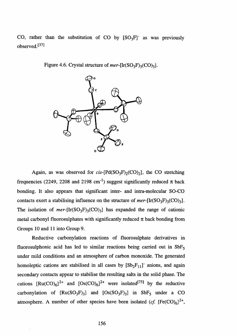
CO, rather than the substitution of CO by [S 0 3 F]' as was previously
observed P 7^
Figure 4.6. Crystal structure of mer-[Ir(S0 3 F)3 (C0 )3 ] .
Again, as was observed for cw-[Pd(S03 F)2 (C 0)2] , the CO stretching
frequencies (2249, 2208 and 2198 cm-1) suggest significantly reduced n back
bonding. It also appears that significant inter- and intra-molecular SO-CO
contacts exert a stabilising influence on the structure of mer- [Ir(S0 3 F)3 (C 0)3] .
The isolation of mer- [Ir(S0 3 F)3 (C 0)3] has expanded the range of cationic
metal carbonyl fluorosulphates with significantly reduced n back bonding from
Groups 10 and 11 into Group 9.
Reductive carbonylation reactions of fluorosulphate derivatives in
fluorosulphonic acid has led to similar reactions being carried out in SbF5
under mild conditions and an atmosphere of carbon monoxide. The generated
homoleptic cations are stabilised in all cases by [Sb2 F n ]' anions, and again
secondary contacts appear to stabilise the resulting salts in the solid phase. The
cations [Ru(CO)6]2+ and [Os(CO)6]2+ were isolated^75! by the reductive
carbonylation of [Ru(S0 3 F)3] and [Os(S03 F)3] in SbF5 under a CO
atmosphere. A number of other species have been isolated (c f [Fe(CO)6]2+,
156
[Ir(CO)6]2+, [Hg(CO)2]2+, [Pt(CO)4]2+ and Pd(CO ) 4 ] 2 + ) . 1 7 3 '7 6 - 7 8 1 The latter two
species are generated by carbonylation of the complexes [ds-P t(S0 3 F)2 (C 0)2]
and [c/.s-Pd(S03 F)2 (C 0)2], in SbF5 under a carbon monoxide atmosphere.
The ability of fluorosulphate ligands to form inter- and intra-molecular
contacts appears to be a significant factor in stabilising these types of species.
As the expansion of this area continues the role of the fluorosulphate anion, and
similar anions (e.g. [Sb2 F n ]~) should become clearer.
4.7.2. Super acids.
Anhydrous hydrogen fluoride and fluorosulphonic acid are the strongest
known Brpnsted acids. They each have identical Hammett acidity functions,
-H0, of 151, and are considerably more acidic than conventional aqueous acid
systems such as nitric or sulphuric acid (i.e. 106 - 101 0 times). They are
generally referred to as super acids and are essentially non aqueous, this is
important since the strongest acid which can exist in the presence of H2 0 , is
[H3 0 ] +. The Hammett acidity function^7,67! is used as a scale by which the
acidity of super acid systems can be gauged, and is defined in Equation 4.28.
H 0 = p t f B H + - l o g { [BH+] / [B]} Eqn. 4.28.
B is an indicator base and [BH+] is its protonated form, pKBH+ is equal to
-logK where K is the dissociation constant of [BH+], the ratio of [BH+] to [B]
may be determined spectrophotometrically.
Early work suggested that anhydrous HF had a value of -H0 of 11,
however, recent studies have indicated that this value is too low . t 7 9 1 It appears
that as the acids approach 1 0 0 % purity and become anhydrous there is a rapid
increase in -H0. This is due to a rapidly increasing concentration of the solvated
proton. Autoprotolysis of HF and H S03F results in the formation of the
following species, [H2 F]+ and [H2 S 0 3 F]+. Due to the problems involved in
157
obtaining 100% anhydrous HF the presence of small concentrations of basic
impurities, such as water, drastically decreases the value of -H0.
The use of fluorosulphonic acid as opposed to anhydrous HF is far more
desirable, this is because fluorosulphonic acid has a wider liquid range, and as
stated earlier, specialised equipment is not required to handle it. These acids are
employed in industrial processes and academic research.[7,66] As reaction media
they have been used to generate a wide range of highly reactive organic and
inorganic cations. In solution, they stabilise these otherwise short-lived species
by virtue of their high acidities and the low nucleophilicity of the conjugate
base ion. The high acidity of fluorosulphonic acid is due to the formation of the
[H2 S 0 3 F]+ (Eqn. 4.29).
2 H S 0 3F [H2 S 0 3 F]+ + [S 0 3 F]' Eqn. 4.29.
Amongst the most powerful super acids the highest acidities are
observed in conjugate superacid system s,^ which usually consist of a strong
protonic acid and a powerful Lewis acid. The conjugate superacid system,
H S 0 3 F-SbF5, is often termed ’magic acid'. This system is quite complex, owing
to facile fluoride versus fluorosulphate exchange and the presence of
concentration dependent solute association via -0 S 0 2 F- and -F- bridgesJ28̂
These factors give rise to the presence of several anions in solution and, as a
result, the use of this system during the synthesis of salts with electrophilic
cations is a problem.
This difficulty can be avoided by using a conjugate super acid system of
the type H S 0 3 F-E(S0 3 F)n, where E (S0 3 F)n is a high oxidation state binary
fluorosulphate acting as a Lewis acid (Eqn. 4.30) typically, E = Au (n = 3), Pt
(n = 4), Nb or Ta (n = 5). These systems all have inherent problems which
include the high price and oxidising ability of Au(III) and Pt(IV) and the
limited thermal stability of the Ta and Nb systems.
158
2 m HSO3F + E (S0 3F)n m [H 2S 0 3F]+ + [E(S03F)n+m]m- Eqn. 4.30.
The usefulness of these superacid media is determined by three general
properties which are demonstrated by the system H S 0 3 F-Au(S0 3 F)3:-
1) The proton donor strength should be very high and is limited by the acidity of
[H2 S 0 3 F]+.
2) The nucleophilicity or electron pair donor ability of the conjugate base ion,
[Au(S0 3 F)4] \ should be very low.
3) The electron pair acceptor strength or Lewis acidity of the molecular Lewis
acid should be high.
Some current research is directed towards finding alternative conjugate
superacid systems, and this involves the synthesis of a range of binary and
ternary fluorosulphates. Such an investigation led to the isolation of
[M (S0 3 F)4] and Cs2 [M (S0 3 F)6] species, where M = Ti, Zr or Hf However,
all three Group four binary fluorosulphates are insoluble in H S0 3 F. The
acceptor ability of these compounds is demonstrated by the isolation of the
ternary fluorosulphates, which are thermally stable up to 260°C. The
[M (S0 3 F)4] systems are polymeric and demonstrate the intrinsic acceptor
ability of the metal centre. Only where there is a limited tendency towards
polymer formation, e.g. [Au(S0 3 F)3] which is dimeric, is it feasible to use
binary fluorosulphates in conjugate H S 03F super acid systems.
159
4.8. Area of Study.
The use of fluorosulphonic acid as an oxidising agent is an area of
chemistry which is little explored. On the other hand, the use of bis-
fluorosulphuryl peroxide as an oxidative-addition reagent is well established,
however, the difficulty involved in its preparation has restricted its use to a few
institutions. Brazier and Woolf and Aubke et alS50 ̂have demonstrated that
fluorosulphonic acid possesses some oxidising powers. Whether this oxidising
prowess is due to the presence of sulphur trioxide is unknown, S 0 3 will
undoubtedly be present in small quantities as an equilibrium product.
Initial experiments were carried out in this laboratory to establish the
similarities between AHF and H S 0 3 F. This involved the protonation of the
carbonyl clusters [Ir4 (CO)12], [Ru3 (CO)12] and [Os3 (CO)12]. In the present
work it was envisaged that the presence of fluorosulphate anions might
facilitate the formation of crystals and allow definitive characterisation of these
protonated carbonyl clusters.
Further reactions were carried out on a variety of metal carbonyl
complexes and Group 4 cyclopentadienyl derivatives. Here, it was hoped that
the presence of the carbonyl groups would facilitate the oxidation of these
species, and that, hopefully, this would establish new synthetic routes to
transition metal fluorosulphate complexes.
160
4.9. The Reactions of [Ir4 (CO)i2], [Ru3 (CO)i2] and
[Os3 (CO)i2] with H S03F.
The protonation of the carbonyl clusters [Ir4 (CO)12], [Ru3 (CO)12] and
[0 8 3 (0 0 )!2] has been previously reported. Early studies by Knight et. al.
employed the use of concentrated H2 S0 4,̂ 8°] whereas more recent work by
Hope et al. used AHFJ81̂
Anhydrous HF is a convenient solvent for the fluorination of transition-
metal carbonyls. It was observed by NMR spectroscopy that protonated
transition-metal carbonyl complexes were present in solution, and this
suggested that HF is not an inert solvent in these reactions. The carbonyl
clusters [Ru3 (CO)12], [Os3 (CO)12] and [Ir4 (CO)12] react with AHF to produce
[Ru3 (CO)1 2 H]+, [Ru(CO)5 H]+, [Os3 (CO)1 2 H]+, [Os(CO)5 H]+ and
[Ir4 (CO)1 2 H2]2+ respectively, and were characterised in solution by a
combination of *H and 13C NMR spectroscopy.
These reactions were repeated using H S 0 3 F, where it was hoped that the
resulting fluorosulphate anions would facilitate the formation of crystals, and so
allow the definitive characterisation of these species as solids.
Fluorosulphonic acid was condensed separately into three FEP tubes
which contained the transition metal carbonyl clusters [Ir4 (CO)12], [Ru3 (CO)12]
and [Os3 (CO)12] respectively. All three solids dissolved immediately and, in
the case o f [Ir4 (CO)12], this is in stark contrast to the AHF reaction where
dissolution occurs only slowly over eight hours. The FEP vessels were sealed
and analyses were undertaken by JH and 13C NMR spectroscopy. The above
reactions were repeated in an identical manner and the fluorosulphonic acid
was slowly removed under vacuum. The intention was to isolate crystals which
could be analysed by X-ray diffraction, however, in each case fine powders
were obtained and attempts to recrystallise these powders using dried solvents
did not result in the formation of any suitable crystals.
161
Triosmium dodecacarbonyl dissolved in HSO3 F at room temperature to
give a yellow solution for which the ]H and 13C NMR revealed the presence of
three protonated species. The NMR spectra revealed that these three species
were identical to those observed during the dissolution of [Os3 (CO)12] in
AHF.[81] A proton resonance at 8-8.2 ppm (cf 8-8.5 ppm in HF) and a 13C
resonance at 8160.8 ppm (d 2 /(CH) = 3.1 Hz) [c f 8159.0 ppm (d 2 /(CH) = 3.0
Hz) in HF] were assigned to the mononuclear [Os(CO)5 H]+, no resonance
could be observed for the CO,ran5-H, presumably because this species is a
minor component in the solution. This species was previously confirmed by a
proton study of the reaction of [Os(CO)5] with 98% H2 S 0 4 J 82̂
Also observed were a proton resonance at 8-19.6 ppm (cf 8-20.3 ppm in
HF) and five 13C resonances at 8173.7 (d 2 /(CH) = 3.2 Hz), 8170.8, 8168.9,
8163.9 and 8161.8 ppm (d 2 /(CH) = 7.1 Hz) (cf 8176.4, 8169.8 (d 2 J(CH) = 2.9
Hz), 8165.1, 8167.0 (d 2 /(CH) = 2.0 Hz) and 8159.5 ppm (d 2 /(CH) = 7.0 Hz)
in HF), and these were assigned to [Os3 (CO)1 2 H]+J81,83̂ Finally, a proton
resonance at 820.1 ppm and 13C resonances at 8155.2 and 8154.1 ppm were
evident, these are consistent with the AHF reaction, however, this third minor
complex remains unassigned.
The proton NMR spectrum of the golden orange solution of
[Ru3 (CO)12] in H S 03F solution showed two hydride signals at 8-7.2 and 8-19.1
ppm (c f 8-7.9 and 8-19.4 ppm in AHF). The latter resonance, characteristic of a
bridging hydride, is assigned to [Ru3 (CO)1 2 H]+ and also corresponds to the
peak at 8-19.4 ppm reported as the only resonance from a solution of
[Ru3 (CO)12] in 98% H2 S 0 4 J 80̂ The first peak corresponds to that at -7.2 ppm
reported for [Ru(CO)5 H]+ from the reaction of [Ru(CO)5] and concentrated
H 2 S 0 4 J 82 ̂ In order to observe a complete 13C NMR spectrum for these species,
13CO enrichment is required^8 ̂ and to record the spectrum at low temperature.
This was deemed unnecessary as the reactivity of this system appears identical
to that observed for the dissolution of [Ru3 (CO)12] in AHF.
162
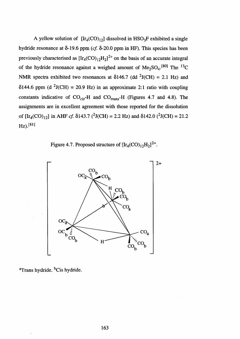
A yellow solution of [Ir4 (CO)12] dissolved in HSO3 F exhibited a single
hydride resonance at 8-19.6 ppm (c f 8-20.0 ppm in HF). This species has been
previously characterised as [Ir4 (CO)1 2 H2]2+ on the basis of an accurate integral
of the hydride resonance against a weighed amount of Me2 S 0 4 J 80̂ The 13C
NMR spectra exhibited two resonances at 8146.7 (dd 2 J(CH) = 2.1 Hz) and
8144.6 ppm (d 2 J(CH) = 20.9 Hz) in an approximate 2:1 ratio with coupling
constants indicative of COcl5-H and COtrans-H (Figures 4.7 and 4.8). The
assignments are in excellent agreement with those reported for the dissolution
of [Ir4 (CO)12] in AHF c f 8143.7 (2 J(CH) = 2.2 Hz) and 8142.0 (2 J(CH) = 21.2
H z).^
Figure 4.7. Proposed structure of [Ir4 (CO)1 2 H2]2 +
CO,OC: CO,
OC;
OC CO.CO,
CO,CO,
2+
aTrans hydride. bCis hydride.
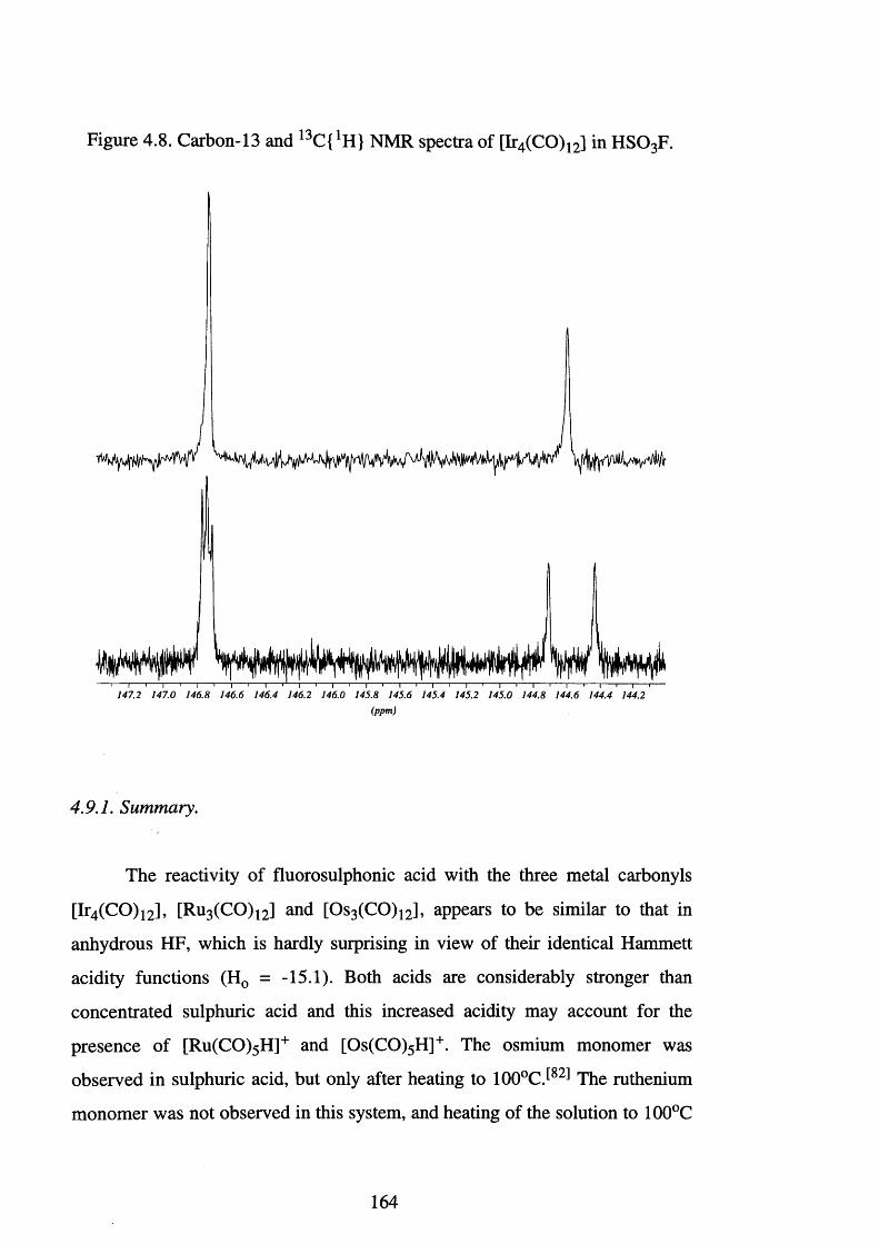
Figure 4.8. Carbon-13 and 13C{ 1H} NMR spectra of [Ir4(CO)12] in HSO3F.
147.2 147.0 146.8 146.6 146.4 146.2 146.0 145.8 145.6 145.4 145.2 145.0 144.8 144.6 144.4 144.2(ppm)
4.9.1. Summary.
The reactivity of fluorosulphonic acid with the three metal carbonyls
[Ir4(CO)12], [Ru3 (CO)12] and [Os3 (CO)12], appears to be similar to that in
anhydrous HF, which is hardly surprising in view of their identical Hammett
acidity functions (H0 = -15.1). Both acids are considerably stronger than
concentrated sulphuric acid and this increased acidity may account for the
presence of [Ru(CO)5 H]+ and [Os(CO)5 H]+. The osmium monomer was
observed in sulphuric acid, but only after heating to 100°CJ82̂ The ruthenium
monomer was not observed in this system, and heating of the solution to 100°C
164
only resulted in decomposition. With AHF or HSO3 F, [Os(CO)5 H]+ and
[Ru(CO)5 H]+ were observed at room temperature, and the ruthenium monomer
was observed in a greater abundance than the osmium analogue. This may be a
consequence of the metal-metal bond strength, which has previously^84! been
noted to increase down the group.
In the osmium case it was also noted that strong acid media such as AHF
or HSO 3 F resulted in the formation of an unknown bridging hydride species J81!
The presence of a significant resonance in the lH NMR spectrum, for the
osmium reaction, suggests that this species must contain more than one
equivalent bridging hydride to account for its the relative intensity. Therefore, it
appears that the use of very strong protonic acids has two noticeable affects
over the less acidic concentrated sulphuric acid, namely:- i) strong acids appear
to promote cluster fragmentation and ii) for the [Os3 (CO)12] reaction a third
hydride species is noted, as yet unassigned.
In the case of [Os3 (CO)12], the formation of a mono hydrogen bridged
complex occurred readily. The use of the strong superacids, AHF and H S0 3 F,
may result in the formation of a bis or tris hydride bridged complex,
[Os3 (CO)1 2 H2]2+ or [Os3 (CO)1 2 H3]3+ respectively. Deeming et a l
demonstrated that the substitution of carbonyl ligands in [0 8 3 (0 0 )!2] by
tertiary phosphines, increased the Lewis basicity of the complex, and made
multiprotonation more favourable.^82! The alternative to this, is to increase the
acidity of the proton donating species, thereby making multiprotonation more
favourable.
The formation of a bis hydride complex, which would result in five
different carbonyl environments and therefore, five different resonances in the
13C NMR spectrum, does not fit the 13C NMR data obtained. Presently there
are two unassigned resonances, however, the formation of the tris hydride
would result in just two carbonyl environments, those carbonyls trans to a
hydride and an equal number cis. The formation of such a complex would be
165
expected to carry some multiplicity. No multiplicity is observed for the
unassigned signals, this may be the result of fluxional behaviour.
It seems apparent that the use of a conjugate superacid system may
unravel this. The use of a system such as A u(S0 3 F ) 3 / H S 03F would serve two
purposes:- i) A system such as this offers increased acidity, which should
increase the amount of the monomer or the unknown bridged hydride species,
ii) The [Au(S0 3 F)4]‘ conjugate base is a bulky anion of low nucleophilicity. It
may prove ideal for the growth of crystals of [Ir4 (CO)1 2 H2]2+ and
[M3 (CO)1 2 H]+ (M = Ru and Os). The obvious drawback of such a system,
however, is the potential oxidising ability of the Au(III) centre.
4.10. The Reaction Between [Fe2 (CO)9 ] and HSO3F.
Iron is rapidly oxidised in moist air and in its finely divided form is
pyrophoric. It readily dissolves in dilute mineral acids which, in the absence of
air or oxidising acids, produces Fe(II)J67,85̂ The use of warm dilute nitric acid
or the presence of air usually results in the formation of some Fe(III). Strong
oxidising media, such as concentrated H N 03, passivate the metal and prevent
complete reaction. Brazier and Woolf observed that iron did not react with
boiling fluorosulphonic acid[49̂ which, in view of the low oxidising prowess of
sulphuric acid, is surprising. This lack of reactivity may be the result of
passivation. The reaction between [Fe3 (CO)12] and H 2 S 0 4, as noted earlier,
results in decomposition of the carbonyl cluster As a consequence of this,
the reaction between [Fe2 (CO)9] and H S03F was attempted as a convenient
route to [Fe(S0 3 F)2] or [Fe(S0 3 F)3].
Fluorosulphonic acid was condensed on to dark yellow platelets of
[Fe2 (CO)9] in a FEP tube at -196°C. On warming to room temperature, a
reaction commenced as evidenced by the evolution of a gas. Analysis of the gas
by gas-phase infrared spectroscopy identified it as carbon monoxide. Removal
of the fluorosulphonic acid produced a dark green solid.
166
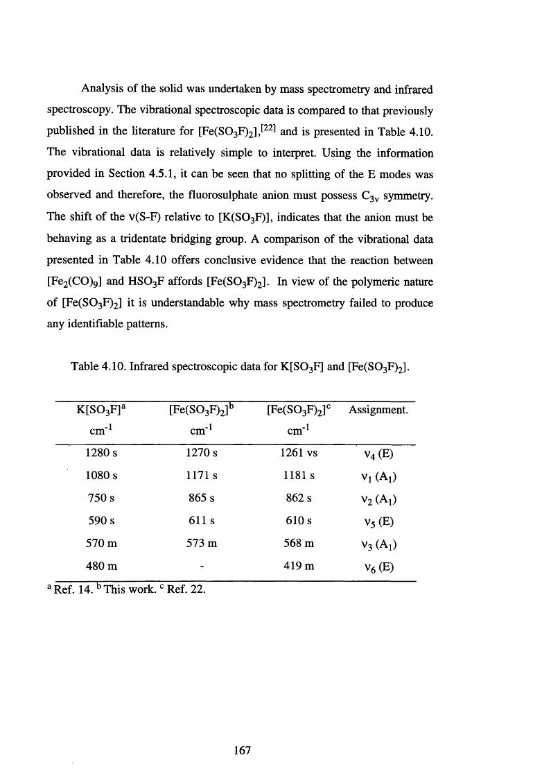
Analysis of the solid was undertaken by mass spectrometry and infrared
spectroscopy. The vibrational spectroscopic data is compared to that previously
published in the literature for [Fe(S03 F)2],[22] and is presented in Table 4.10.
The vibrational data is relatively simple to interpret. Using the information
provided in Section 4.5.1, it can be seen that no splitting of the E modes was
observed and therefore, the fluorosulphate anion must possess C3v symmetry.
The shift of the v(S-F) relative to [K(S0 3 F)], indicates that the anion must be
behaving as a tridentate bridging group. A comparison of the vibrational data
presented in Table 4.10 offers conclusive evidence that the reaction between
[Fe2 (CO)9] and H S 03F affords [Fe(S0 3 F)2] . In view of the polymeric nature
of [Fe(S0 3 F)2] it is understandable why mass spectrometry failed to produce
any identifiable patterns.
Table 4.10. Infrared spectroscopic data for K[SQ3 F] and [Fe(SQ3 F)2].
K [S 0 3 F]a
cm"1
[Fe(S0 3 F)2]b
cm'1
[Fe(S0 3 F)2]c
cm"1
Assignment.
1280 s 1270 s 1261 vs v4 (E)
1080 s 1171 s 1181 s Vi (Aj)
750 s 865 s 862 s v2 (Al)
590 s 611 s 610 s v 5 (E)
570 m 573 m 568 m v 3 (Aj)
480 m - 419 m v 6 (E)
a Ref. 14. b This work. 0 Ref. 22.
167
4.11. The Reaction Between Re or Mn Carbonyl Derivatives and
HSO3F.
The complexes [M (C0)5 (S 0 3 F)] (M = Mn and Re) have been
synthesised previously The compounds are produced by the reaction of
[M(CO)5 X] (M = Mn, Re; X = Cl, Br) with A g[S0 3 F] in a suitable solvent. In
the case of rhenium the reaction proceeds very smoothly, however, the
manganese reaction is rather slower and complete substitution is only observed
when the reaction is carried out over five days using [Mn(CO)5 Br].
Four reactions were attempted and these used the readily available
starting materials [Mn2 (CO)10], [MeMn(CO)5], [Re2 (CO)10] and [Re(CO)5 Cl].
All the reactions were carried out in FEP vessels, and the fluorosulphonic acid
was condensed into the tubes at -196°C.
The reaction between [Mn2 (CO)10] and HS0 3F commenced upon
warming the mixture to room temperature, as evidenced by the production of a
gas which was identified by gas phase infrared spectroscopy as carbon
monoxide. During the course of the reaction a solid was precipitated. Once the
reaction was judged to be complete, the fluorosulphonic acid was removed
under reduced pressure and a dark green solid was isolated. Analysis was
undertaken using mass spectrometry and infrared spectroscopy.
Mass spectrometry failed to produce any identifiable patterns and
infrared spectroscopy also met with no success. The infrared spectrum showed
no carbonyl absorptions and the sulphur-oxygen and sulphur-fluorine region
consisted of several very broad absorptions. No useful information was
obtained and repetition of the experiment provided no improvements. The solid
was insoluble in a range of solvents, including fluorosulphonic acid, and this
suggests a polymeric nature.
The reaction between [MeMn(CO)5] and H S03F occurred upon
warming the mixture to -78°C, and continued for approximately 30 minutes.
168
Analysis of the gas produced, by gas-phase infrared spectroscopy, showed only
the presence of methane. During the course of the reaction, solid was
precipitated. On completion of the reaction the fluorosulphonic acid was
removed under reduced pressure. Attempts were made to obtain infrared and
mass spectral data, however, as observed for the [Mn2 (CO)10] reaction, no
characterisable spectra were produced. The infrared spectrum showed two
strong absorptions at 2131 and 2087 cm-1. This indicated the presence of
carbonyl groups within the product, and implied a different reaction scheme to
that observed for the [Mn2 (CO)10] reaction. A comparison of these carbonyl
absorptions to those of the starting material [MeMn(CO)5] (cf. 2082, 1997 and
1947 cm '1) and the anticipated product [Mn(C0)5 (S 0 3 F)] (cf. 2140, 2056,
2030, 2000, 1972 cm '1) indicates neither was present in the product. The region
1500-600 cm ' 1 was dominated by strong, broad absorptions and no information
could be obtained.
The reactions between [Re2 (CO)10] or [Re(CO)5 Cl] and fluorosulphonic
acid occurred steadily at room temperature and, upon removal of the
fluorosulphonic acid, produced a brown coloured solid. Analysis of the gas
evolved from the [Re(CO)5 Cl] reaction did not show the presence of HC1 but
rather HF. This was unexplained, but may be the result of an exchange reaction
occurring within the solution. Both reactions produced a solid of the same
colour, however, it is noted that the reaction between [Re(CO)5 Cl] and
A g[S 0 3 F] produced a white crystalline solidJ19̂
The infrared spectroscopic data is presented in Table 4.11 and is
compared with the previously published data for [Re(C0)5 (S 0 3 F)] and
K [S 0 3 F]. T w o important features highlight the ionic nature of the
fluorosulphate group within the product. The sulphur-fluorine stretch is
observed in the same region as that for K [S0 3 F]: any strong covalent
interaction at the oxygens is expected to strengthen this bond. The symmetric
169
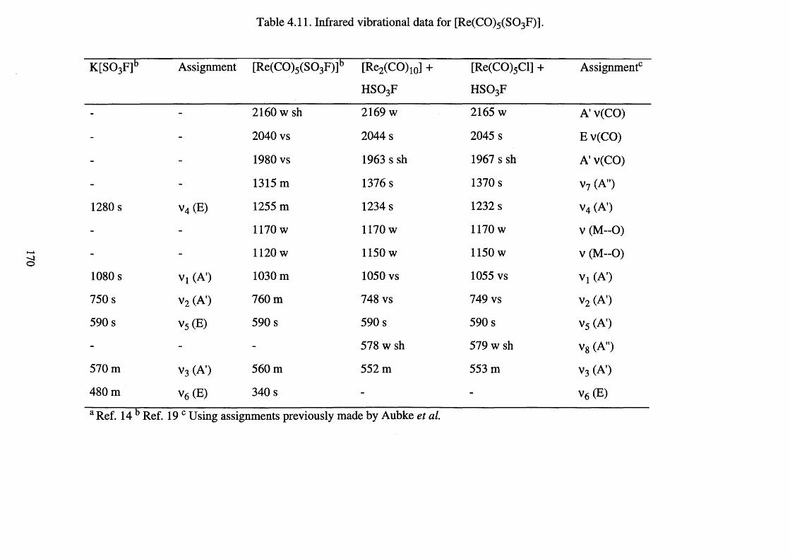
Table 4.11. Infrared vibrational data for [Re(C0)5(S 0 3F)].
K [S0 3 F]b Assignment [Re(C0)5 (S 0 3 F)]b [Re2 (CO)10] +
h s o 3f
[Re(CO)5 Cl] +
h s o 3f
Assignment0
- - 2160 w sh 2169 w 2165 w A v(CO)
- - 2040 vs 2044 s 2045 s Ev(CO)
- - 1980 vs 1963 s sh 1967 s sh A' v(CO)
- - 1315 m 1376 s 1370 s v7 (A")
1280 s v 4 (E) 1255 m 1234 s 1232 s v 4 (A )
- - 1170 w 1170 w 1170 w v (M—0 )
- - 1 1 2 0 w 1150 w 1150 w v (M -O )
1080 s Vl (A’) 1030 m 1050 vs 1055 vs Vi (A)
750 s v 2 (A’) 760 m 748 vs 749 vs v 2 (A')
590 s V5 (E) 590 s 590 s 590 s v5 (A)
- - - 578 w sh 579 w sh V8 (A")
570 m v 3 (A) 560 m 552 m 553 m v 3 (A)
480 m V6 (E) 340 s - - v6 (E)
a Ref. 14 b Ref. 19 c Using assignments previously made by Aubke et al.
S 0 3 stretch is also found in the same region as that for K [S 0 3 F] and the
splitting of the asymmetric S 0 3 stretch, observed at 1280 cm ' 1 for K [S0 3 F], is
indicative of a departure from C3v symmetry. Removal of the degeneracy for
this E mode is small, but not as small as that observed by Aubke et a l. It is
noted here that the splitting is - 1 2 2 cm ' 1 as opposed to that reported earlier of
60 cm"1. As previously stated, these splittings are too large to be due to site
effects and are interpreted as indicative of an ionic interaction as opposed to a
covalent one, this is apparent by comparison of this data with that in Table 4.5.
The carbonyl stretching region contained three absorptions which are
expected for a pentacarbonyl derivative. A comparison of this carbonyl
stretching data with that in Table 2.14, again highlights the highly ionic nature
of the bonding within this complex, similar to that observed for the seflate and
teflate derivatives.
The data provided here thus indicates that the reaction between
fluorosulphonic acid and [Re2 (CO)10] or [Re(CO)5 Cl] produces
[Re(C0)5 (S 0 3 F)] as the major product.
Confirmation of the formation of [Re(CO)5 (S 0 3 F)] was provided by El
and FAB mass spectrometry. For both experiments, the following species were
identified:- [Re(C0)5 (S 0 3 F)]+ m/z = 426, [Re(C0)4 (S 0 3 F)]+ m/z = 398 and
[Re(CO)5]+ m/z = 327.
The 13C NMR spectra on the products of both reactions were recorded in
H S 0 3 F. The reaction between [Re2 (CO)10] and H S 03F produced a 13C NMR
spectrum with two resonances at 5182.1 and 5179.3 ppm, relative intensities
4:1. On the basis of the previous evidence these resonances are assigned to the
species [Re(C0)5 (S 0 3 F)]. The reaction between [Re(CO)5 Cl] and H S03F
showed four resonances in the 13C NMR spectrum, 5182.0 and 5179.3 ppm
with relative intensities 4:1, and 5181.4 and 5176.5 ppm with relative
intensities 4:1. The two sets of signals have an integration ratio of 3:1,
suggesting that the major product constitutes 75% of the species produced.
Considering the vibrational spectra, which did not show absorptions due to the
171
presence of [Re(CO)5 Cl], and the similarity of the chemical shifts to that
observed for the [Re2 (CO)1 0 ]-HSO3F reaction, the major species formed was
[Re(C0)5 (S 0 3 F)]. The second species present was undoubtedly [Re(CO)5 Cl]
and the failure to observe the expected v(CO) absorptions at 2155, 2046 and
1983 cm '1, was a consequence of the presence of the strong absorptions of
[Re(C0)5 (S 0 3 F)] which dominated that region of the spectrum. Separation of
the products was attempted using a range of solvents, however, the solubilities
of the two materials appeared very similar.
4.12. The Reaction Between HSO3F and [CP2MX2 ]
(M = Ti, Zr or Hf, X = Me or Cl).
In order to extend the range of fluorosulphate derivatives an attempt was
made to synthesise [Cp2 M (S0 3 F)2], where M = Ti, Zr or Hf. Recent work
carried out at Leicester revealed that [Cp2 MX2], where X = Me or Cl,
underwent clean displacement reactions with teflic acid, HOTeF5, to form
[Cp2 M(OTeF5)2] Analysis of the products revealed bis-teflate substitution
at the metal centre and intact r |5-cyclopentadienyl ligands. Proton-1 NMR
spectroscopic data for [Cp2 MX2] (M = Ti, Zr or Hf, X = Cl or OTeF5) and the
teflate spectroscopic data indicated that the metal-teflate bond was extremely
ionic in nature. Complexes of the general type [Cp2 MX2] (where X = Cl, alkyl
or aryl) are well studied and exchange or reduction reactions are of significant
synthetic potential for example, in alkene polymerisation.
The reactions between fluorosulphonic acid and [Cp2 MX2] (M = Ti, Zr
or Hf, X = Me or Cl) were attempted. Samples of [Cp2 TiCl2], [Cp2 ZrMe2],
[Cp2 ZrCl2] and [Cp2 HfCl2] were placed separately into passivated FEP tubes.
Using a metal vacuum line, excess of fluorosulphonic acid was condensed on to
the samples at -196°C. On warming to room temperature, in each case an
immediate reaction occurred, as evidenced by the evolution of a gas. The
172
reactions were extremely vigorous and required quenching several times with
an acetone-cardice slush. The gases generated were identified using infrared
spectroscopy as methane for the [Cp2 ZrMe2] reaction and hydrogen chloride
from the other reactions. On completion, all four reactions gave black, viscous,
almost solid materials. Excess of fluorosulphonic acid appeared to be
incorporated in the product mixtures, and it proved impossible to remove under
reduced pressures. The materials formed in each case were undoubtedly
polymeric and analysis by a series of spectroscopic techniques failed to give
any indication about their composition.
Excess of fluorosulphonic acid was condensed on to a sample of orange
[Cp2 TiMe2] at -196°C. On warming to -78°C an immediate reaction occurred
as evidenced by the evolution of a gas. The gas was identified as methane using
gas phase infrared spectroscopy. The reaction continued for approximately
twenty minutes after which time it appeared to be complete. The resulting
solution was black as in the above examples, however, the mixture was
significantly less viscous. Removal of the H S 03F proved difficult, and elevated
temperatures (ca. ~100°C) and prolonged pumping under dynamic vacuum
were required. The isolated solid was dark purple in colour.
Analysis of the solid by FAB mass spectrometry identified the fragment
[Cp2 Ti]+ m/z =178. The infrared vibrational data are presented in Table 4.12,
also listed, for comparison, are the infrared vibrational data for K[Br(S03 F)4],
for which a covalent monodentate interaction exists between the fluorosulphate
ligand and the bromine centred13̂ The infrared spectroscopic data provide
conclusive evidence for the formation of a covalent monodentate interaction
between the titanium centre and the fluorosulphate group. The distinguishing
features of the spectrum are contained in the region 1500-800 cm '1, i.e. the
sulphur-oxygen and sulphur-fluorine stretching region (Section 4.5.1). A total
of 7 absorptions were observed in the above region and this indicated that the
symmetry of the fluorosulphate anion had been lowered to Cs (N.B. 3
173
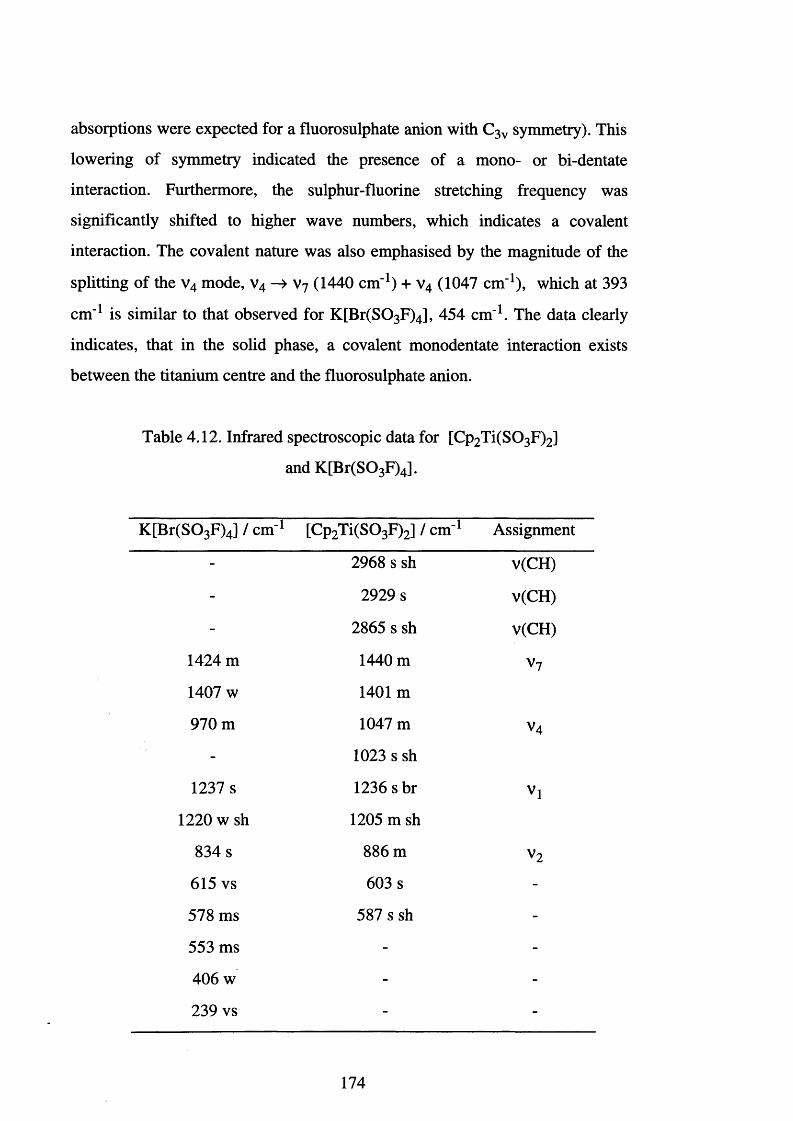
absorptions were expected for a fluorosulphate anion with C3v symmetry). This
lowering of symmetry indicated the presence of a mono- or bi-dentate
interaction. Furthermore, the sulphur-fluorine stretching frequency was
significantly shifted to higher wave numbers, which indicates a covalent
interaction. The covalent nature was also emphasised by the magnitude of the
splitting of the v 4 mode, v 4 —> v 7 (1440 cm '1) + v4 (1047 cm"1), which at 393
cm " 1 is similar to that observed for K[Br(S0 3 F)4], 454 cm '1. The data clearly
indicates, that in the solid phase, a covalent monodentate interaction exists
between the titanium centre and the fluorosulphate anion.
Table 4.12. Infrared spectroscopic data for [Cp2 T i(S0 3 F)2]
and K[Br(S0 3 F)4].
K [Br(S0 3 F)4] / cm - 1 [Cp2 T i(S0 3 F)2] / cm ' 1 Assignment
- 2968 s sh v(CH)
- 2929 s v(CH)
- 2865 s sh v(CH)
1424 m 1440 m v 7
1407 w 1401m
970 m 1047 m V4
- 1023 s sh
1237 s 1236 s br Vl
1 2 2 0 w sh 1205 m sh
834 s 8 8 6 m v 2
615 vs 603 s -
578 ms 587 s sh -
553 ms - -
406 w - -
239 vs - -
174
Multinuclear NMR spectra were recorded for the reaction mixture,
[Cp2 TiMe2 ]-H S0 3 F. Proton-1 NMR experiments showed a single resonance at
87.2 ppm which originated from the equivalent protons of the rj5-
cyclopentadienyl groups. Fluorine-19 NMR experiments showed a doublet at 5
57.8 ppm, J = 5.8 Hz, which became a singlet when the experiments were run
in proton decoupling mode. Carbon-13 ^ H ) NMR experiments showed a
singlet at 8129.3 ppm, which originated from the r\5-cyclopentadieny 1 groups.
A comparison of the *H NMR chemical shifts for the compounds
[Cp2 TiX2] (X = -S 0 3 F, -OTeF5, -F and -Cl) is presented in Table 4.13. As can
be seen, the resonance arising from the cyclopentadienyl protons is shifted to
higher frequency as one ascends the table. A similar pattern was observed for
the Zr and Hf derivatives, but are not due to steric effects Excluding the
fluorosulphate group, the trend observed is interpreted in terms of the ability of
the ligands to undergo pn —» dn bonding, fluorine being the strongest n donor
but the weakest n acceptor. As the ability to pn —> dn bond decreases so the
Cp-metal interaction increases. The ]H NMR data for [Cp2 Ti(S0 3 F)2] is not
strictly comparable as solvent effects have not been accounted for. However,
the NMR data suggests, that the interaction of the fluorosulphate groups in
solution is highly ionic in nature. This is not surprising in view of the high
ionising ability of fluorosulphonic acid which presumably dominates in favour
of covalent bonding. The resulting interaction requires the Cp ligands to donate
more electron density to the metal centre, therefore, resulting in deshielding of
the cyclopentadienyl protons.
In the solid state, however, the fluorosulphate groups are covalently
bound to the titanium centre. This is in contrast to [Cp2 Ti(OTeF5)2], where the
spectroscopic data clearly indicated that the titanium-teflate bonds possess a
large degree of ionic character. This obviously reflects the fundamental
differences between the teflate and fluorosulphate groups as ligands. Although
the central atoms, S and Te, are both in their maximum oxidation states their
175
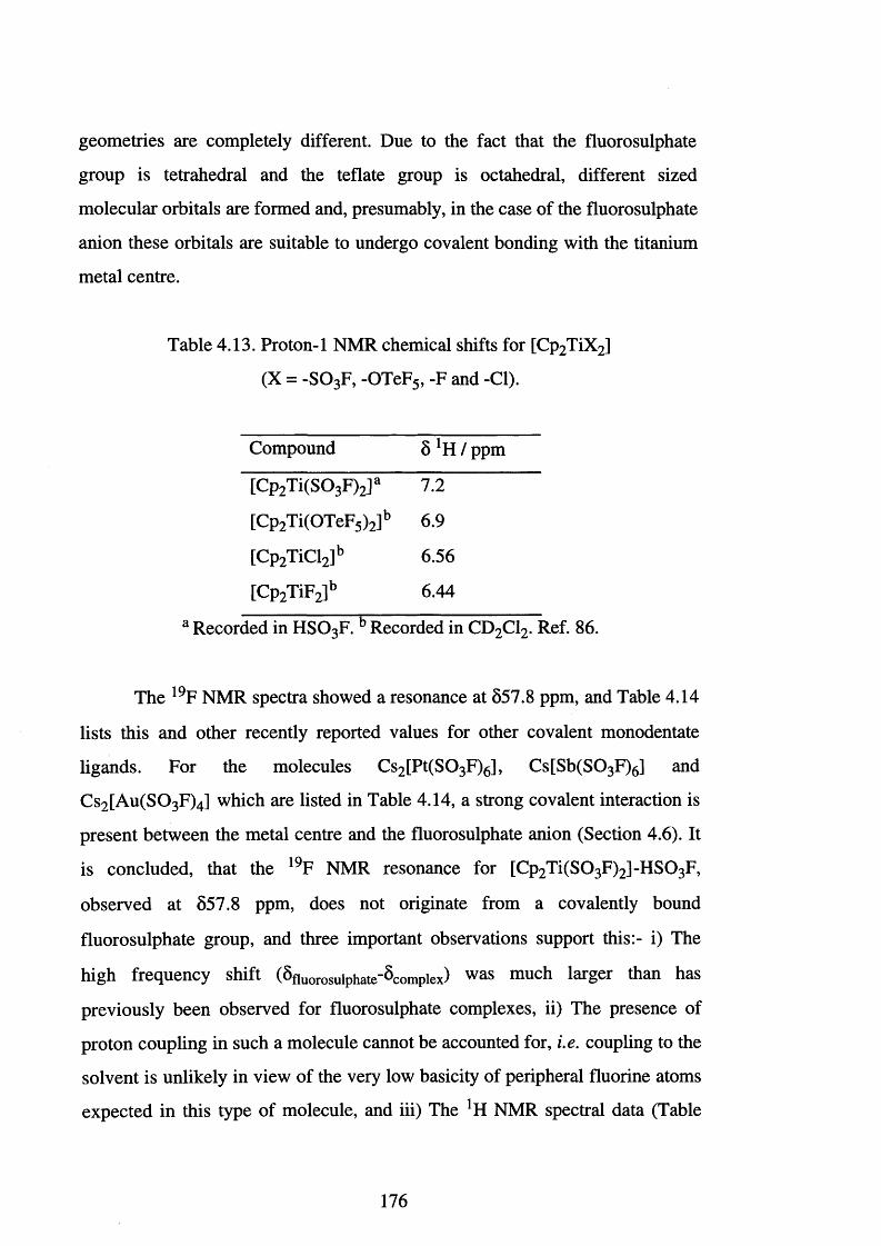
geometries are completely different. Due to the fact that the fluorosulphate
group is tetrahedral and the teflate group is octahedral, different sized
molecular orbitals are formed and, presumably, in the case of the fluorosulphate
anion these orbitals are suitable to undergo covalent bonding with the titanium
metal centre.
Table 4.13. Proton-1 NMR chemical shifts for [Cp2 TiX2]
(X = -SO3 F, -OTeF5, -F and -Cl).
Compound 8 lH / ppm
[Cp2Ti(S03 F)2]a 7.2
[Cp2 Ti(OTeF5)2]b 6.9
[Cp2 TiCl2]b 6.56
[Cp2 TiF2]b 6.44
a Recorded in HSO3 F. b Recorded in CD2 C12. Ref. 8 6 .
The 19F NMR spectra showed a resonance at 857.8 ppm, and Table 4.14
lists this and other recently reported values for other covalent monodentate
ligands. For the molecules Cs2 [Pt(S0 3 F)6], Cs[Sb(S0 3 F)6] and
Cs2 [A u(S0 3 F)4] which are listed in Table 4.14, a strong covalent interaction is
present between the metal centre and the fluorosulphate anion (Section 4.6). It
is concluded, that the 19F NMR resonance for [Cp2 T i(S0 3 F)2 ]-H S0 3 F,
observed at 557.8 ppm, does not originate from a covalently bound
fluorosulphate group, and three important observations support this:- i) The
high frequency shift (5fluorosulphate-8compiex) was much larger than has
previously been observed for fluorosulphate complexes, ii) The presence of
proton coupling in such a molecule cannot be accounted for, i.e. coupling to the
solvent is unlikely in view of the very low basicity of peripheral fluorine atoms
expected in this type of molecule, and iii) The *H NMR spectral data (Table
176
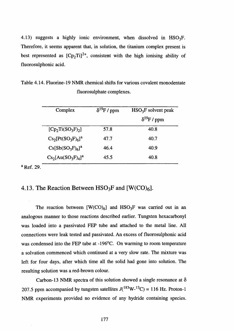
4.13) suggests a highly ionic environment, when dissolved in H S 0 3 F.
Therefore, it seems apparent that, in solution, the titanium complex present is
best represented as [Cp2 Ti]2+, consistent with the high ionising ability of
fluorosulphonic acid.
Table 4.14. Fluorine-19 NMR chemical shifts for various covalent monodentate
fluorosulphate complexes.
Complex 8 19F / ppm HSO3 F solvent peak
8 19F / ppm
[Cp2 T i(S 0 3 F)2] 57.8 40.8
Cs2 [Pt(S0 3 F)6]a 47.7 40.7
Cs[Sb(S0 3 F)6]a 46.4 40.9
Cs2 [Au(S0 3 F)4] a 45.5 40.8
a Ref. 29.
4.13. The Reaction Between HSO3F and [W(CO)6 J.
The reaction between [W(CO)6] and HSO3 F was carried out in an
analogous manner to those reactions described earlier. Tungsten hexacarbonyl
was loaded into a passivated FEP tube and attached to the metal line. All
connections were leak tested and passivated. An excess of fluorosulphonic acid
was condensed into the FEP tube at -196°C. On warming to room temperature
a solvation commenced which continued at a very slow rate. The mixture was
left for four days, after which time all the solid had gone into solution. The
resulting solution was a red-brown colour.
Carbon-13 NMR spectra of this solution showed a single resonance at 8
207.5 ppm accompanied by tungsten satellites / ( 1 8 3 W -1 3 C) =116 Hz. Proton-1
NMR experiments provided no evidence of any hydride containing species.
177
Attempts to remove the fluorosulphonic acid and obtain a solid sample proved
difficult, elevated temperatures and prolonged pumping resulting in a black
viscous oil. Mass spectrometry did not show any identifiable patterns, and
infrared spectroscopy only revealed a single, strong absorption at 2004 cm '1.
The spectroscopic evidence obtained for this reaction compares well to that
reported in the literature for [W(CO)6].[87] The reported 13C NMR resonance
for [W(CO)6] in CH2 C12 is 5192.1 ppm, / ( 1 8 3 W-1 3 C) = 126 Hz and the infrared
carbonyl absorption is at 1998 cm '1.
This has led us to conclude that no reaction occurs between [W(CO)6]
and H S 0 3 F. The variation in the NMR data is almost certainly due to solvent
effects and this has previously been highlighted (Table 2.5).
The infrared spectroscopic data obtained for the reaction product is also
consistent with that reported in the literature for [W(CO)6]. Our inability to
remove all the fluorosulphonic acid and obtain solid [W(CO)6] is indicative of
some degree of association. Several broad, rather small intensity absorptions
observed in the region 1500-400 cm '1, are indicative of the sulphur-oxygen and
sulphur-fluorine stretching region, and are almost certainly associated with
HSO 3 F wrapped in the [W(CO)6] lattice.
4.14. The Reaction Between [Mo(CO)6 ] and HSO3F.
Molybdenum hexacarbonyl was loaded into a passivated FEP tube,
attached to a metal vacuum line and all connections leak tested and then
passivated. Fluorosulphonic acid was condensed on to the white solid at
-196°C. Upon warming to room temperature, a slow reaction occurred as
evidenced by the production of a gas which, was identified using infrared
spectroscopy as CO. The reaction was left over a period of four days after
which time no gas evolution was observed and it was judged to be complete.
Removal of the fluorosulphonic acid was very difficult and required pumping
178
under dynamic vacuum for one week. The solid isolated was a dark blue,
almost black, colour.
Infrared spectroscopy of the residual solid showed the following
absorptions; 2158 s, 2059 s, 1377 vs, 1106 vs vbr, 985 wsh, 841 m, 722 m, 619
w and 556 m cm '1. A comparison of the CO absorptions, 2158 and 2059 cm '1,
to that for [Mo(CO)6], c f 2004 cm 'V 88̂ shows a shift to higher wavenumbers
indicating oxidation of the Mo centre.
Proton-1 NMR experiments did not show any hydride containing species
and carbon-13 NMR experiments showed a single resonance at 5203.3 ppm.
The 13C NMR spectral resonance at 5203.3 ppm is due to the presence of
unreacted [Mo(CO)6] {cf 5202.0 ppm for [Mo(CO)6] in CH2 C12).[88]
A comparison of the vibrational data with the data discussed in Section
4.5.1 shows the only certain feature in the fluorosulphate region is the sulphur-
fluorine stretch which, at 841 cm '1, implies a significant covalent interaction.
The sulphur-oxygen region was dominated by a broad absorption centred at
1107 cm " 1 {N.B. 1320-950 cm '1), making a firmer assignment impossible.
4.15. The Reactions Between and [Co2 (CO)s] or [Cr(CO)6 ] and
HSO3F.
The reaction between fluorosulphonic acid and [Co2 (CO)8] or [Cr(CO)6]
was carried out in an analogous manner to those described previously. Both
reactions produced carbon monoxide gas and over the course of the reaction a
black insoluble solid formed. Attempts to dissolve these solids in a variety
solvents failed, and analysis by mass spectrometry and infrared spectroscopy
produced no characterisable spectra. The infrared spectra did not show any
absorptions in the carbonyl stretching region.
179
4.16. Summary.
Although some success was obtained with these reactions, the
combination of metal vacuum lines and FEP apparatus with fluorosulphonic
acid is far from ideal. Work-up may take as long as a week and usually involves
prolonged pumping under dynamic vacuum. Further development of these
synthetic reactions is likely to be more suited to the use of glass reaction vessels
and Schlenk vacuum lines.
The reactions of fluorosulphonic acid with the organometallic
complexes outlined in this Chapter is not a general route to metal
fluorosulphate derivatives. However, in certain cases, identifiable products
have been obtained. The compounds [Fe(S0 3 F)2] and [Re(CO)5 (S 0 3 F)],
although previously available, have now been prepared by more direct routes.
These reactions also demonstrate that fluorosulphonic acid possesses mild
oxidising abilities. Woolf et al. previously reported that iron and rhenium metal
are both inert to boiling fluorosulphonic acidj49 ̂ so that the presence of the
carbonyl ligands has clearly played a part in facilitating the oxidation of the
metal (0 ) centre.
The reaction between [Cp2 TiMe2] and H S 03F has established a route to
the previously unknown [Cp2 Ti(S0 3 F)2] . This represents a new synthetic
approach to obtaining fluorosulphate derivatives and also demonstrates, for the
first time, that cyclopentadienyl and fluorosulphate groups are mutually
compatible. It is likely, therefore, that further developments will occur in this
area.
180
References Chapter Four
[1] Thorpe, T. F. and Kirman W. J., J. Chem. Soc., 1892, 61,921.
[2] A. Engelbrecht, Angew. Chem., Int. Ed. Engl., 1965, 4 ,641.
[3] R. C. Thompson, Inorganic Sulphur Chemistry, Elsevier, ed. G.
Nickless, 1968, ch. 17, 587-606 and references cited therein.
[4] R. J. Gillespie, Acc. Chem. Res., 1968,1, 202.
[5] R. J. Gillespie and T. Birchall, Can. J. Chem., 1963, 4 1 ,148.
[6 ] CRC Handbook o f Chemistry and Physics, ed. R. C. Weast, 57th edn.
1979.
[7] G. A. Olah, G. K. S. Prakash and L. Sommer, Superacids, Wiley, New
York, 1985 and references cited therein.
[8 ] R. J. Gillespie and J. Liang, J. Am. Chem. Soc., 1988,110,6053.
[9] R. Jost and J. Sommer, Rev. Chem. Intermed., 1988, 9,1.
[10] R. D. Howells and J. D. McCown, Chem. Rev., 1977, 77,69.
[11] A. A. Woolf, J. Chem. Soc., 1954, 2840.
[12] H. Willner, S. J. Rettig, J. Trotter and F. Aubke, Can. J. Chem., 1991,
69,391.
[13] H. A. Carter, S. P. L. Jones and F. Aubke, Inorg. Chem., 1970, 9,2485.
[14] J. Gorbeau and J. B. Milne, Can. J. Chem., 1967, 45,2321.
[15] W. V. Cicha and F. Aubke., J. Fluorine Chem., 1990, 47, 317.
[16] D. Zhang, S. J. Rettig, J. Trotter and F. Aubke., Inorg. Chem., 1996,35,
6113.
[17] C. Wang, M. Bodenbinder, H. Willner, S. J. Rettig, J. Trotter and F.
Aubke., Inorg. Chem., 1994, 33,779.
[18] S. P. Mallela, S. Yap and F. Aubke, Inorg. Chem., 1986, 25,4074.
[19] S. P. Mallela and F. Aubke, Inorg. Chem., 1985, 24, 2969.
[20] M. Einsenberg and D. D. Des Marteau, Inorg. Chem., 1972,11, 2641.
[21] S. P. Mallela, K. Lee, P. F. Gehrs, J. I. Christensen, J. R. Sams and F.
Aubke, Can. J. Chem., 1987, 65, 2649.
181
[22] C. S. Alleyne, K. O. Mailer and R. C. Thompson, Can. J. Chem., 1974,
52, 336.
[23] A. W. Jache, Adv. Inorg. Chem. Radiochem., 1974,16, 177 and
references therein..
[24] F. Aubke, M. S. R. Cader and F. Minstry, Synthetic Fluorine Chemistry,
eds. G. A. Olah, R. D. Chambers and G. K. S. Prakash, Wiley, New
York, 1992, pg. 43 and references therein.
[25] J. M. Shreeve and G. H. Cady., Inorg. Synth., 1963, 7 ,124.
[26] D. Zhang, S. J. Rettig, J. Trotter and F. Aubke., Inorg. Chem., 1995, 34,
2269 and references therein.
[27] W. V. Cicha, F. G. Herring and F. Aubke, Can. J. Chem., 1990, 6 8 ,102.
[28] F. Mistry and F. Aubke, J. Fluorine Chem., 1994, 6 8 , 239.
[29] D. Zhang, S. J. Rettig, J. Trotter and F. Aubke., Inorg. Chem., 1996, 35,
6113.
[30] F. B. Dudley and G. H. Cady, J. Am. Chem. Soc., 1957, 79,513.
[31] S. Singh and R. D. Verma, Ahstr. Int. Symp. Fluorine Chem. 10th,
Vancouver, Aug. 1982 Abstr. 1-76.
[32] S. D. Brown and G. L. Gard, Inorg. Nucl. Chem. Lett., 1975,11 ,19.
[33] C. J. Schack and K. O. Christe, Inorg. Nucl. Chem. Lett., 1978,14,293.
[34] P. C. Leung and F. Aubke, J. Fluorine Chem., 1979, 14, 347.
[35] A. Smalc, Vestn. Slov. Kem. Drus., 1974, 21,5.
[36] G. H. Cady, Inorg. Synth., 1968,11, 155.
[37] C. Wang, A. R. Lewis, R. J. Batchelor, F. W. B. Einstein, H. Willner and
F. Aubke, Inorg. Chem., 1996, 3 5 ,1279.
[38] F. B. Dudley and G. H. Cady, J. Am. Chem. Soc., 1963, 85 ,3375.
[39] A. A. Woolf, J. Chem. Soc. (A), 1967, 355.
[40] A. Storr, P. A. Yeats and F. Aubke, Can. J. Chem., 1971, 50,452.
[41] S. Singh, M. Bedi and R. D. Verma, J. Fluorine Chem., 1982, 20, 107.
[42] P. C. Leung and F. Aubke, Inorg. Chem., 1978,17, 1765.
[43] J. E. Roberts and G. H. Cady, J. Am. Chem. Soc., 1960, 92, 352.
182
[44] K. C. Lee and F. Aubke, Can. J. Chem., 1977, 55,2437.
[45] W. M. Johnson, R. Dev and G. H. Cady, Inorg. Chem., 1972,11,2260.
[46] K. C. Lee and F. Aubke, J. Fluorine Chem., 1982,19, 501.
[47] A. A. Woolf, J. Fluorine Chem., 1971,1,127.
[48] H. C. Clark and H. J. Emeleus, J. Chem. Soc., 1957, 4778.
[49] J. N. Brazier and A. A. Woolf, J. Chem. Soc. (A), 1967, 99.
[50] D. Zhang, S. J. Rettig, J. Trotter and F. Aubke., Inorg. Chem., 1995, 34,
3153.
[51] R. J. Gillespie and O. C. Vaidya, J. Chem. Soc., Chem. Commun., 1972,
40.
[52] K. C. Lee and F. Aubke, Can. J. Chem., 1981, 59 ,2835.
[53] P. C. Leung and F. Aubke, Inorg. Nucl. Chem. Lett., 1977,13, 263.
[54] E. L. Muetterties and D. D. Coffman, J. Am. Chem. Soc., 1958, 80,
5914.
[55] E. L. Muetterties, J. Amer. Chem. Soc., 1958, 80, 5911.
[56] P. A. Yeats, B. L. Poh, B. F. E. Ford, J. R. Sams and F. Aubke, J. Chem.
Soc. (A), 1970, 2188.
[57] G. Hwang, C. Wang, M. Bodenbinder, H. Willner and F. Aubke, J.
Fluorine Chem., 1994, 6 6 , 159.
[58] A. M. Qureshi, H. A. Carter and F. Aubke, Can. J. Chem., 1971, 49, 35.
[59] F. H. Allen, J. A. Lerscher and J. Trotter, J. Chem. Soc. (A), 1971, 2507.
[60] F. A. Hohorst and J. M. Shreeve, Inorg. Chem., 1966, 5, 2069.
[61] T. Birchall, G. Denes, R. Faggiani, C. S. Frampton, R. J. Gillespie, R.
Kapoor and J. E. Vekris, Inorg. Chem., 1990, 2 9 ,1527.
[62] D. C. Adams, T. Birchall, R. Faggiani, R. J. Gillespie and J. E. Vekris,
Can. J. Chem., 1991, 69, 2122.
[63] S. P. Mallela, S. T. Tomic, K. Lee, J. R. Sams and F. Aubke, Inorg.
Chem., 1986, 25, 2939.
[64] J. R. Sams, R. C. Thompson and T. B. Tsin, Can. J. Chem., 1977, 55,
115.
183
[65] A. L. Arduini, M. Garnett, R. C. Thompson and T. C. T. Wong, Can. J.
Chem., 1975, 53, 3812.
[6 6 ] F. Aubke, Inorganic Fluorine Chemistry : Towards the 21st Century,
eds. J. S. Thraser and S. H. Strauss, American Chemical Society,
Washington, 1994, pg. 350.
[67] F. A. Cotton and G. Wilkinson, Advanced Inorganic Chemistry, 5th ed.,
1988.
[6 8 ] P. Schtitzenberger, C. R. Hebd. Seances Acad. Sci., 1870, 7 0 ,1134; P.
Schtitzenberger, C. R. Hebd. Seances Acad. Sci., 1870,7 0 ,1287; P.
Schtitzenberger, Bull. Chim. Fr., 1870,14,97.
[69] H. Willner and F. Aubke, Inorg. Chem., 1990, 29,2195.
[70] W. M. Johnson, R. Dev and G. H. Cady, Inorg. Chem., 1972,11,2260.
[71] K. C. Lee and F. Aubke, Inorg. Chem., 1979,18,389.
[72] K. C. Lee and F. Aubke, Inorg. Chem., 1984, 23, 2124.
[73] G. H. Hwang, C. Wang, F. Aubke, H. Willner and M. Bodenbinder,
Can. J. Chem., 1993, 7 1 ,1532.
[74] C. Wang, H. Willner, M. Bodenbinder, R. J. Batchelor, F. W. B.
Einstein and F. Aubke, Inorg. Chem., 1994, 33, 3521.
[75] C. Wang, B. Bley, G. Balzer-Jollenbeck, A. R. Lewis, S. C. Siu, H.
Willner and F. Aubke., J. Chem. Soc., Chem. Commun., 1995, 2071.
[76] B. Bley, H. Willner and F. Aubke, Inorg. Chem., 1997, 3 6 ,158.
[77] C. Bach, H. Willner, C. Wang, S. J. Rettig, J. Trotter and F. Aubke,
Angew. Chem., Int. Ed. Engl., 1996, 35,1974.
[78] M. Bodenbinder, G. Balzer-Jollenbeck, H. Willner, R. J. Batchelor, F.
W. B. Einstein, C. Wang and F. Aubke, Inorg. Chem., 1996, 35,92.
[79] R. J. Gillespie and J. Liang. J. Am. Chem. Soc., 1988,110, 6053.
[80] J. Knight and M. J. Mays, J. Chem. Soc. (A), 1970, 711.
[81] S. A. Brewer, J. H. Holloway and E. G. Hope, J. Fluorine Chem., 1995,
7 0 ,167.
184
[82] A. J. Deeming, B. F. G. Johnson and J. Lewis, J. Chem. Soc. (A), 1970,
2697.
[83] A. A. Koridze, O. A. Kizas, N. M. Astakhova, P. V. Petrovskii and Y.
K. Grishinn, J. Chem. Soc., Chem. Commun., 1981, 853.
[84] C. O. Quicksall and T. S. Spiro, Inorg. Chem., 1968, 7, 2365; B. F. G.
Johnson, J. Lewis and P. A. Kilty, J. Chem. Soc., 1968, 2839.
[85] N. N. Greenwood and A. Eamshaw, Chemistry o f the Elements,
Pergamon, Oxford, 1st ed., 1984, ch. 25, pg. 1250.
[8 6 ] M. C. Crossman, Ph.D. Thesis, University of Leicester, 1995 and
references cited therein.
[87] Comprehensive Oranometallic Chemistry, eds. E. W. Abel, F. G. A.
Stone and G. Wilkinson, Pergamon Press, Oxford, 1982, vol 3, ch 28
and references cited therein.
[8 8 ] Comprehensive Oranometallic Chemistry, eds. E. W. Abel, F. G. A.
Stone and G. Wilkinson, Pergamon Press, Oxford, 1982, vol 3, ch 27
and refences cited therein.
185
CHAPTER FIVE
Experimental
5.1. Handling of Materials.
Most of the inorganic materials prepared and studied in this thesis are
air- and moisture-sensitive. To prevent decomposition they were either handled
on a metal vacuum line with facilities to connect glass or fluoroplastic reaction
vessels via Teflon™ couplings or in an inert atmosphere dry box.
5.1.1. Metal vacuum line.
This consisted of 316 stainless steel or Monel Autoclave Engineers'
valves [AE-30 series, Autoclave Engineers Inc.] connected via Autoclave
Engineers connectors. Argon-arc welded nickel 'U' traps were incorporated to
permit separation and condensation of gases in the metal manifold. Inlets for
argon [BOC Special Gases] and fluorine [Distillers MG] were positioned as
shown in Figure 5.1. Rough pump vacuum outlets were connected to a soda
lime chemical scrubber to neutralise any volatile fluorides, thereby protecting
the rough pump [Model PSR/2, NGN Ltd.] which provided a vacuum of 10‘ 2
mmHg. High vacuum was obtained via outlets to a mercury diffusion pump
coupled to a second NGN pump. This gave a vacuum in the region of 10‘ 5
mmHg. The mercury diffusion pump was protected by a glass trap in liquid
nitrogen between the metal line and the diffusion pump to condense volatile
products or fluorides from the metal line that remained after evacuation using
the rough pump. The second rotary pump was protected by a second glass trap
cooled with solid carbon dioxide to condense any mercury vapour before it
could enter the rotary pump.
5.1.2. Inert atmosphere dry box.
Involatile fluorides were manipulated in an auto-recirculating positive-
pressure dry box [Vacuum Atmospheres Co., VAC NE-42 Dri Lab.]
186
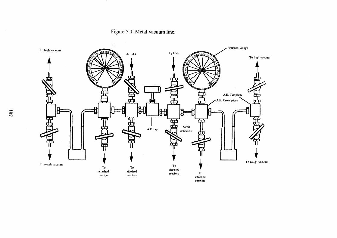
Figure 5.1. Metal vacuum line.
To high vacuum
9 = f i (r
To rough vacuum
F„ hi letAr Inlet
8 = 1 mMetal
connectorA.E. tap
attached
attachedreactors
Bourdon Gauge
To high vacuum
A.E. Tee piece
A E . Cross piece
13= ^ ( r ^
To rough vacuum
Toattachedreactors
Toattachedreactors
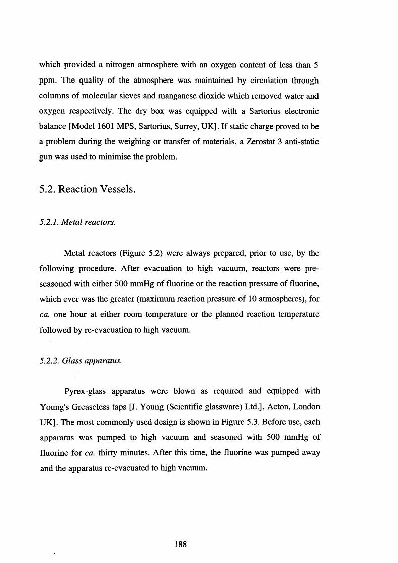
which provided a nitrogen atmosphere with an oxygen content of less than 5
ppm. The quality of the atmosphere was maintained by circulation through
columns of molecular sieves and manganese dioxide which removed water and
oxygen respectively. The dry box was equipped with a Sartorius electronic
balance [Model 1601 MPS, Sartorius, Surrey, UK]. If static charge proved to be
a problem during the weighing or transfer of materials, a Zerostat 3 anti-static
gun was used to minimise the problem.
5.2. Reaction Vessels.
5.2.1. Metal reactors.
Metal reactors (Figure 5.2) were always prepared, prior to use, by the
following procedure. After evacuation to high vacuum, reactors were pre
seasoned with either 500 mmHg of fluorine or the reaction pressure of fluorine,
which ever was the greater (maximum reaction pressure of 1 0 atmospheres), for
ca. one hour at either room temperature or the planned reaction temperature
followed by re-evacuation to high vacuum.
5.2.2. Glass apparatus.
Pyrex-glass apparatus were blown as required and equipped with
Young's Greaseless taps [J. Young (Scientific glassware) Ltd.], Acton, London
UK]. The most commonly used design is shown in Figure 5.3. Before use, each
apparatus was pumped to high vacuum and seasoned with 500 mmHg of
fluorine for ca. thirty minutes. After this time, the fluorine was pumped away
and the apparatus re-evacuated to high vacuum.
188
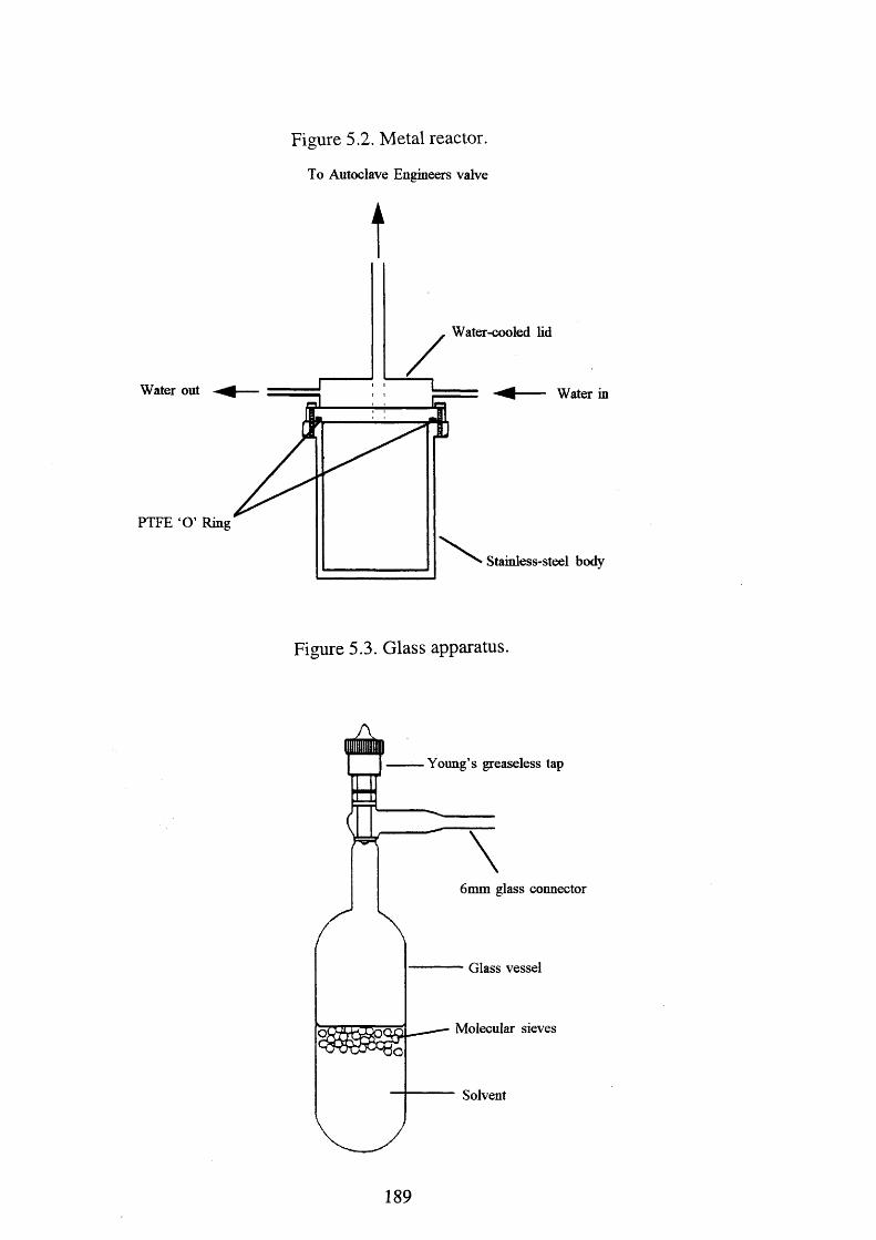
Figure 5.2. Metal reactor.
To A utoclave Engineers valve
tW ater-cooled lid
Water out Water in
PTFE ‘O ’ R ing
Stainless-steel body
Figure 5.3. Glass apparatus.
Y oung’s greaseless tap
6mm glass connector
Glass vessel
M olecular sieves
Solvent
189
5.2.3. Fluoroplastic apparatus.
In general, for the reactions carried out in fluoroplastic, a straightened 6
nun o.d. FEP reactor was first prepared by sealing at one end by heat moulding
into a 7 mm i.d. glass tube. This was then connected to Chemcom coarse-
control needle valves [Type STD/VC-4, Production Techniques] by a PTFE 'O'
compression union. Before the introduction of the reagents, the system was
evacuated to approximately 10' 4 mmHg to ensure that a vacuum-tight system
had been obtained, passivated with 500 mmHg of fluorine and re-evacuated to
high vacuum. Non-volatile products were loaded into the evacuated FEP tubes
in a dry box and then placed back on the vacuum line. The connectors were re
evacuated and passivated as above. Volatile reagents and solvents could be
transferred into these tubes under static vacuum (Figure 5.4). For large scale
reactions, 12 mm o.d. FEP tubes were prepared (sealed at one end by heat
moulding into a 13 mm i.d. glass tube) and used in a similar manner. For small
scale reactions, 4 mm o.d. FEP tubes were prepared (sealed at one end by heat
moulding into a 5 mm NMR tube) and connected to the vacuum line in a
similar manner to that described above. After reaction, the solvent was either
removed to permit the analysis of the resulting product, or the tubes were sealed
under vacuum, by heating with a small ring oven whilst the solution remained
frozen at -196°C. The resulting sealed FEP tube and its contents could then be
examined by NMR spectroscopy.
Highly reactive and corrosive liquids were stored in passivated Kel-F
vessels fitted with a Chemcom tap. These vessels were connected to a metal
vacuum line in an identical manner to that above, thus facilitating transfer of
these materials under static or dynamic vacuum.
190
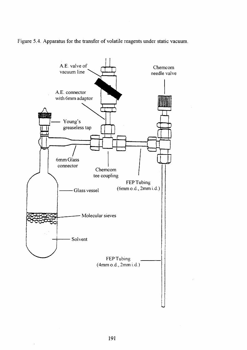
Figure 5.4. Apparatus for the transfer of volatile reagents under static vacuum.
A.E. valve o f vacuum line
A.E. connector with 6mm adaptor
Chemcom needle valve
U T T )
Youna sgreaseless tap
6mm Glass connector
rJ
1jChemcom
tee coupling
Glass vessel
FEP Tubing (6mm o.d., 2mm i.d.)
Molecular sieves
Solvent
FEP Tubing (4mm o.d., 2mm i.d.)
191
9868
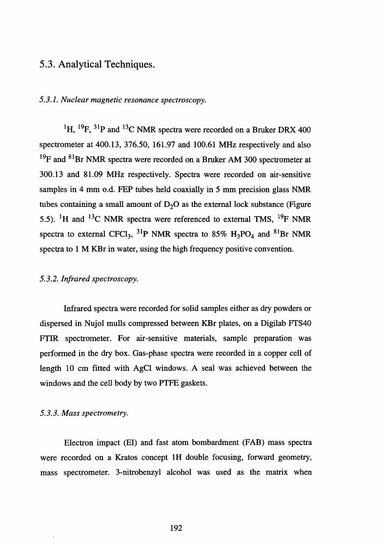
5.3. Analytical Techniques.
5.3.1. Nuclear magnetic resonance spectroscopy.
1 H, 1 9 F, 31P and 13C NMR spectra were recorded on a Bruker DRX 400
spectrometer at 400.13, 376.50, 161.97 and 100.61 MHz respectively and also
19F and 81Br NMR spectra were recorded on a Bruker AM 300 spectrometer at
300.13 and 81.09 MHz respectively. Spectra were recorded on air-sensitive
samples in 4 mm o.d. FEP tubes held coaxially in 5 mm precision glass NMR
tubes containing a small amount of D20 as the external lock substance (Figure
5.5). *H and 13C NMR spectra were referenced to external TMS, 19F NMR
spectra to external CFC13, 31P NMR spectra to 85% H3 PO4 and 81Br NMR
spectra to 1 M KBr in water, using the high frequency positive convention.
5.3.2. Infrared spectroscopy.
Infrared spectra were recorded for solid samples either as dry powders or
dispersed in Nujol mulls compressed between KBr plates, on a Digilab FTS40
FTIR spectrometer. For air-sensitive materials, sample preparation was
performed in the dry box. Gas-phase spectra were recorded in a copper cell of
length 10 cm fitted with AgCl windows. A seal was achieved between the
windows and the cell body by two PTFE gaskets.
5.3.3. Mass spectrometry.
Electron impact (El) and fast atom bombardment (FAB) mass spectra
were recorded on a Kratos concept 1H double focusing, forward geometry,
mass spectrometer. 3-nitrobenzyl alcohol was used as the matrix when
192
Figure 5.5. NMR samples fitted inside a 5 mm o.d. precision NMR tube.
FEP Tube (4mm o.d., 3mm i.d.)
Cap
r 'Precision Glass NMR Tube (5mm o.d.)
Deuterated Solvent
Sample
193
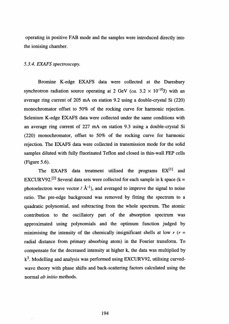
operating in positive FAB mode and the samples were introduced directly into
the ionising chamber.
5.3.4. EXAFS spectroscopy.
Bromine K-edge EXAFS data were collected at the Daresbury
synchrotron radiation source operating at 2 GeV (ca. 3.2 x 10"1 0 J) with an
average ring current of 205 mA on station 9.2 using a double-crystal Si (220)
monochromator offset to 50% of the rocking curve for harmonic rejection.
Selenium K-edge EXAFS data were collected under the same conditions with
an average ring current of 227 mA on station 9.3 using a double-crystal Si
(220) monochromator, offset to 50% of the rocking curve for harmonic
rejection. The EXAFS data were collected in transmission mode for the solid
samples diluted with fully fluorinated Teflon and closed in thin-wall FEP cells
(Figure 5.6).
The EXAFS data treatment utilised the programs E X ^ and
EXCURV 92.^ Several data sets were collected for each sample in k space (k =
photoelectron wave vector / A '1), and averaged to improve the signal to noise
ratio. The pre-edge background was removed by fitting the spectrum to a
quadratic polynomial, and subtracting from the whole spectrum. The atomic
contribution to the oscillatory part of the absorption spectrum was
approximated using polynomials and the optimum function judged by
minimising the intensity of the chemically insignificant shells at low r (r =
radial distance from primary absorbing atom) in the Fourier transform. To
compensate for the decreased intensity at higher k, the data was multiplied by
k3. Modelling and analysis was performed using EXCURV92, utilising curved-
wave theory with phase shifts and back-scattering factors calculated using the
normal ab initio methods.
194
Figure 5.6. FEP cell used for the collection of EXAFS data.
Assembled cell
Gap 0.12 mm
Wall 0.6 mm
Exploded section
Section of wall and gap
FEP
Stainless steel
5.4. Solvents.
5.4.1. Anhydrous hydrogen fluoride.
Hydrogen fluoride (ICI pic) was distilled direct from the cylinder into a
passivated Kel-F vessel fitted with a Chemcom tap. It was then dried for twelve
hours with one atmosphere of fluorine. The fluorine was removed and the HF
stored over BiF5.
5.4.2. Dichloromethane.
Dichloromethane was purified and dried by first shaking it with portions
of concentrated H2S 0 4. This was repeated until the acid layer remained
colourless. It was then washed with water containing 5% Na2C 0 3 and then
water again. The solvent was then pre-dried with CaCl2, distilled from P2Os
and finally distilled from CaH2 under dry nitrogen. The dichloromethane was
195
stored in a glass Schlenk flask over dried 4 A molecular sieves. The solvent
was degassed prior to use.
5.4.3. Acetonitrile.
The acetonitrile was initially dried by shaking with 4 A molecular
sieves. It was then stirred under nitrogen with CaH2 for approximately four
hours. The resulting liquid was then distilled on to fresh P2 0 5 under nitrogen,
retaining only the middle fraction. Finally the middle fraction again was
distilled into a glass Schlenk vessel and stored over dry 4 A molecular sieves. It
was degassed prior to use.
5.4.4. Fluorosulphonic acid.
Fluorosulphonic acid, H S 0 3 F, was transferred, using a dry box, into a
round bottom flask. The round bottom flask, which had previously been dried
with fluorine, had a connector making it possible to attach it to the metal
vacuum line. The fluorosulphonic acid was then degassed and transferred by
distillation into a Kel-F vessel fitted with a Chemcom tap for storage until use.
5.5. Preparation of Fluorides, Oxide Fluorides, Seflate and
Fluorosulphate species.
5.5.1. Preparation ofXeF2-
Xenon difluoride was prepared as described by Holloway,^ 1966.
Xenon was mixed with a 10% excess of fluorine in a preseasoned glass bulb (1
litre volume). The reaction mixture was UV photolysed with mercury discharge
196
lamps (350 nm) for a week, after which time the reaction was considered to be
complete. Unreacted xenon and fluorine were removed in vacuo. The xenon
difluoride was purified by sublimation under dynamic vacuum through a trap at
-78°C. The crystalline solid (yield 100%) was stored in a preseasoned FEP
vessel in the dry box.
5.5.2. Preparation ofXe(OSeF5)2.
Xenon bis(seflate) was prepared as described by Seppelt,^ 1986.
Selenium dioxide, S e0 2 (ca. 40 mmol) was loaded into a passivated autoclave
reaction vessel containing a magnetic stirrer bar. The reaction vessel was then
cooled to -196°C and SF4 (ca. 36 mmol) was condensed on to the Se02. The
reaction vessel was sealed and then, under constant stirring, heated to 120°C for
twelve hours.
The metal trap of the vacuum line was cooled to -78°C and the contents
of the reaction vessel was pumped through it under dynamic vacuum. Selenium
oxide difluoride, SeOF2, the least volatile product of this reaction, was the only
compound isolated in the trap.
Xenon difluoride (ca. 29 mmol) was loaded into a passivated FEP U-
tube containing a magnetic stirrer bar. The FEP U-tube was connected to the
line via Chemcom taps and the connectors were evacuated and passivated. The
FEP U-tube was then cooled to -78°C and pumped to high vacuum. Under
dynamic vacuum the SeOF2 was condensed on to the XeF2 and the FEP U-tube
was then allowed to warm to room temperature. A steady reaction occurred.
The reaction mixture was left open to the line and stirred for twelve
hours. After this time, the system was considered to be at equilibrium and the
volatile products were pumped away using the rough pump. The solid was
pumped for a total of three hours to remove HF and XeF2. The solid white
Xe(OSeF5)2, yield 2.8g (56%), was stored in an preseasoned FEP vessel in the
dry box.
197
5.5.3. Preparation o f K[BrO4].
Potassium perbromate was prepared using the method described by
Appleman, 1972.^ The initial oxidation involves the action of elemental
fluorine on an aqueous alkaline solution of K [Br03]. Consequently, the
experiment was undertaken using fluoroplastic reaction vessels. Ice was packed
around the reaction vessel to dissipate heat produced during the oxidation stage.
Sodium bromate, Na[Br03], (ca. 1.3 mol) was added to a 900 ml
solution of 5M NaOH and stirred mechanically until all the solid dissolved. A
FEP tube was placed into the solution, the other end of the tube was connected
to a metal line which, in turn, was connected via copper piping to cylinders of
fluorine and argon gas. Elemental fluorine was passed into the solution and the
metal line was used to control the rate. Fluorine was introduced into the
solution at a rapid rate, however, care must be taken to avoid undue splattering.
W arning, the reaction must be carefully monitored as, if the temperature of the
solution approaches its boiling point, small detonations may occur in the vapour
above the mixture. Care must also be taken to avoid deposits of solid blocking
the end of the FEP tube. To remove any solid formed, the FEP tube was
removed from the solution and the end cut off, the tube was then flushed with
fluorine before introduction back into the solution.
The oxidation stage was complete within one and a half hours and was
monitored by measuring the pH of the solution. Oxidation only occurs in
alkaline conditions and the pH was measured by extracting a drop of the
solution using FEP tubing and placing it on universal indicator paper. Once the
fluorination was complete (ca. solution turned acidic), the solution was flushed
with a vigorous stream of argon gas (ca. 5 minutes) to remove unreacted
fluorine and oxygen fluoride from the solution and the space above it. The
resulting solution was colourless, free of any deposits and left to cool to room
temperature (ca. 2 0 minutes).
198
The following stages involve the purification of K [Br04] where the use
of glass vessels was avoided except when using the rotary evaporator. Washing
the precipitate involves the use of distilled water to remove any K[Br04] from
the precipitate, the filtrate was added to the original filtrate.
Once the solution had cooled to room temperature, anhydrous Ba(OH ) 2
(ca. 1.75 mol) was slowly added to the solution. The temperature of the
solution rose and it was stirred mechanically until it cooled to room temperature
(ca. 1 hour). The solution was filtered and the precipitate washed several times.
The precipitate, which consisted largely of BaF2 and Ba[Br03]2, was discarded.
The solution was then acidified using Dowex 50X8 cation exchange
resin, 20-50 mesh, in the hydrogen form. The pH of the solution was raised to
1.3, and the Dowex cation exchange resin served to remove sodium from the
solution. The solution was then filtered and the precipitate washed and
discarded. The volume of the solution had now risen to 2 litres and it was
reduced to 400 ml using a rotary evaporator.
The bromate concentration^ was assayed and this showed the presence
of 4.96 g of unreacted bromate. Enough AgF (ca. 6 8 mmol) was added to the
solution to provide a 0.15 M excess over the amount needed to precipitate the
bromate present. The solution was filtered and washed with aqueous AgF (ca.
30 ml of 0.1 M AgF). Calcium hydroxide (ca. 41 mmol) was slowly added to
the solution and this was sufficient to provide a 1 0 % excess above the amount
needed to precipitate the fluorine added in the form of AgF. The solution was
left for one hour to cool to room temperature and then the precipitate was
removed by filtration and washed.
The solution was acidified to pH ~ 1.3 using the Dowex cation exchange
resin, filtered and washed. The solution was neutralised using Ca(OH ) 2 and
then filtered using diatomaceous earth filter aid. The precipitate was washed
with a saturated solution of Ca(OH)2.
199
Dowex cation exchange resin was then added to the solution, which was
acidified up to pH 0.8. The solution was filtered, washed and then reduced in
volume using a rotary evaporator to 2 0 0 ml.
Initially, the solution was neutralised using 4 M KOH but, as the end
point approached, 0.1 M KOH was used. The solution was then reduced in
volume using a rotary evaporator. On cooling with ice, a brown solid was
obtained which was then recrystallised from the minimum volume of water.
The yield of the white K[Br04] was 6 g (2.5 %), it was dried in an autoclave
vessel at 150°C and stored in a dry box.
5.5.4. Reactions involving Xe(OSeF5)2.
The reactions of xenon bis(seflate) were carried out in identical ways.
The reactions were performed using modified apparatus to prevent scorching of
the materials used. A Chemcom tap was connected via 6 mm FEP tubing to a
Chemcom T-piece. Two separate 6 mm FEP tubes, sealed at one end, were
connected to the T-piece. The Chemcom tap was then connected to a metal line,
pumped to high vacuum and passivated with 600 torr of fluorine.
Using an inert atmosphere dry box, xenon bis(seflate) (ca. 0.5 mmol)
was placed in one of the FEP tubes. A stoicheiometric amount of the reactant
(ca. [Re2 (CO)10] 0.5 mmol) was then added to the remaining FEP tube. The
vessel was attached to the line and the connectors were leak tested and
passivated. The vessel was evacuated and dry dichloromethane was condensed
on to the xenon bis(seflate). Once all the xenon bis(seflate) had dissolved it was
decanted on to the reactant. The reaction was quenched, if required, using an
acetone / cardice slush. On completion of the reaction all the volatiles were
removed and the products were stored in the dry box.
200
5.5.5. Preparation ofBrF3.
Bromine trifluorine, BrF3, was distilled from the cylinder into a FEP U-
tube. The BrF3 was brown due to the presence of bromine and this was
removed by direct reaction with fluorine. Fluorine was slowly allowed into the
tube were an immediate reaction occurred. Warning, the addition of fluorine
must be very slow to avoid ignition. The brown colour slowly disappeared to
leave a straw coloured liquid. Two atmospheres of fluorine were placed above
the liquid and was left for two hours with constant stirring. The fluorine was
removed at -78°C and the bromine trifluoride was transferred by distillation to a
Kel-F vessel fitted with a Chemcom tap for storage.
5.5.6. Preparation ofBrF5.
This was distilled directly from the cylinder into an FEP U-tube. The
BrF5 was brown in colour due to the presence of bromine, also present were
bromine trifluoride and HF. The bromine was removed by direct reaction with
fluorine to produce bromine trifluoride. Two atmospheres of fluorine were
placed above the mixture and left, with constant stirring, for two hours. The
fluorine was then removed at -78°C. The U-tube was warmed to -13°C at which
temperature bromine trifluoride has a vapour pressure of 0.3 torr and bromine
pentafluoride a vapour pressure of 62 torr. The bromine pentafluoride was then
distilled into a passivated Kel-F vessel which contained dried NaF: the NaF
removed trace amounts of HF and BrF3.
5.5.7. Preparation ofK[BrF4], K[BrF6] and Cs[BrF6].
Dried KF (ca. 4 mmol) was loaded into a passivated 6 mm FEP tube
fitted with a Chemcom tap, using an inert atmosphere dry box. The tube was
connected to a metal vacuum line and all connections were leak tested and
201
passivated. Bromine trifluoride was condensed under static vacuum on to the
KF. The reaction vessel was shaken for one week at room temperature. After
this time the volatiles were removed and the solid complex stored in the dry
box.
Dried CsF (ca. 4 mmol) was loaded into a passivated 6 mm FEP tube
fitted with a Chemcom tap, using an inert atmosphere dry box. The tube was
connected to a metal vacuum line and all connections were leak tested and
passivated. Bromine pentafluoride was condensed under static vacuum on to
the CsF. The reaction vessel was shaken for one week at room temperature.
After this time the volatiles were removed and the solid complex stored in the
dry box.
The preparation of K[BrF6] was carried out on a larger scale using a 12
mm FEP vessel. Potassium fluoride (ca. 16 mmol) was allowed to react with
BrF5 (ca. 62 mmol) as described above. The reaction vessel was shaken for one
week after which time all the volatiles were removed and the solid stored in the
dry box.
5.5.8 . Preparation o f [BrF2 ][AsF6] and [BrF4 ][Sb2Fj j].
A 6 mm FEP tube was connected via a satellite line to the metal
manifold. Also connected to the satellite were BrF3 and AsF5 or BrF5 and SbF5.
The connectors and reaction vessels were leak tested and passivated. Bromine
trifluoride (ca. 0.6 mmol) or bromine pentafluoride (ca. 0.4 mmol) were then
condensed into the tube.
Arsenic pentafluoride was allowed into the metal line and the reaction
vessel. The uptake of AsF5 was carefully monitored using the metal-line gauge
and once the pressure remained constant all the BrF3 was judged to have
reacted. The solid was pumped under dynamic vacuum to remove excess of
AsF5 and then stored in the dry box.
202
Antimony pentafluoride (ca. 0.5mmol) was condensed on to the BrF5,
which was in excess. An immediate reaction occurred at room temperature and
the solid adduct was obtained by removal of the excess of BrF5 using the rough
pump. The solid was then stored in the dry box.
5.5.9. The Preparation o f Cs[BrOF4].
This was prepared using the method described by Chirste et al., 1987.^
Using an inert atmosphere dry box, Cs[N 03] (ca. 2 mmol) was loaded into a
passivated nickel reaction vessel. The reaction vessel was then attached to the
metal line and the connectors were leak tested and passivated. A five molar
excess of BrF5 was condensed at -196°C into the nickel reaction vessel . The
reaction vessel was warmed to -31°C and shaken occasionally for two to three
hours. The reaction vessel was then re-attached to the metal line and the
connectors were leak tested and passivated. The volatile products were
removed using the rough pump and the solid product stored in the dry box.
5.5.10. The Preparation o f BrO^F.
Potassium perbromate, K[Br04] (ca. 0.7 mmol), was loaded into a
passivated 6 mm FEP tube in a dry box. The FEP tube, along with BrF5 and
HF, were attached to a metal line via a satellite connection. The connections
were then evacuated and passivated. Enough AHF was condensed into the tube
to completely dissolve the K[Br04] . Finally BrF5 (ca. 2 mmol) was condensed
into the FEP tube, and on warming to room temperature, an immediate reaction
occurred.
The reaction vessel was cooled to -78°C and at this temperature B r03F
is the most volatile component of the reaction. The volatiles were condensed
into an FEP tube containing dried NaF at -196°C, the NaF formed an adduct
with the HF leaving a pure source of B r0 3 F.
203
Over time, B r0 3F decomposes with the formation of bromine. This can
be kept to a minimum by storage of the B r03F at liquid nitrogen temperatures.
The bromine may be removed by the addition of a small amount of fluorine into
the FEP tube at liquid nitrogen temperatures. On warming the fluorine and
bromine react to form BrF3, which itself reacts with the NaF to form a solid,
involatile, adduct.
5.5.11. Reactions involving HSO3 F.
In a typical reaction, the solid metal complex (ca. O.lg) was weighed out
in the dry box and loaded into a preseasoned FEP tube. The FEP tube was
connected to the metal vacuum line via a Chemcom tap, and all the connections
were leak tested, passivated and re-evacuated. The FEP tube containing the
metal complex was then cooled to liquid nitrogen temperatures and leak tested.
Fluorosulphonic acid (ca. 3.5g) was condensed into the reaction vessel at
-196°C. The FEP tubing was warmed to -78°C using an acetone-cardice slush,
and then slowly warmed to room temperature. The reaction was quenched, if
necessary, using the acetone-cardice slush.
On completion of the reaction all the volatile materials were removed.
This involved distillation of the excess of fluorosulphonic acid into a second,
empty, FEP tube. This procedure is very time consuming and care must be
taken to avoid bumping of the H S03F at reduced pressures. Once the excess of
H S 03F was removed, the remainder of the volatile materials were pumped
away under dynamic vacuum using the rough pump. This was also very time-
consuming since most of the reaction products appeared to adsorb the
fluorosulphonic acid. This often required the use of elevated temperatures (ca.
100°C) and prolonged pumping (ca. one week). The solid products, if obtained,
were stored in the dry box before analysis.
204
5.5.12. Attempted synthesis ofBrOF3.
The reaction between Li[N 03] and BrF5 was carried out using the
method described by Christe et alP^ 1987. Using a dry box, L i[N 03] (ca. 2
mmol) was loaded into a gold-seal nickel reaction vessel. The reaction vessel
was attached to a metal vacuum line and the connection was leak tested,
passivated and then re-evacuated. The reaction vessel was then opened to the
metal line and leak tested. Bromine pentafluoride (ca. 30 mmol) was distilled
from a Kel-F storage vessel into the reaction vessel. The vessel was sealed and
placed in a Dewar containing acetone. The acetone was cooled using a
refrigeration unit to a temperature of 0°C. The vessel was left at 0°C for twenty
days with occasional agitation.
The vessel was then reconnected to the metal line and all connections
were leak tested and passivated. The reaction cylinder was then cooled to
-196°C and opened to the vacuum line, a small pressure rise was noted. The
reaction was allowed to warm slowly to room temperature under dynamic
vacuum. The volatile materials present were separated by fractional
condensation through a series of traps at -64°C and -196°C. No volatiles were
isolated in the trap at -64°C. Analysis using 19F NMR spectroscopy, at 0°C,
only produced resonances due to BrF5. No resonances at or around 8 164 ppm
were observed. Analysis of the solid product identified only K[BrF4].
In view of the presence of K[BrF4] the reaction was attempted at lower
temperatures: in order to minimise the apparent decomposition of BrOF3.
Subsequent reactions were carried out at -10°C and -20°C, in an analogous
manner to that outlined above. Two further reactions were performed using
larger and smaller excesses of BrF5. These reactions only produced BrF5 and
K[BrF4] as the identifiable products.
205
5.5.13. Attempted synthesis o f B r02F.
This reaction was carried out using the method described by Gillespie et
al., 1976.^ Potassium bromate (c.a. 8 mmol) was loaded into a passivated Kel-
F vessel fitted with a Chemcom tap. The Kel-F vessel and vessels containing
AHF and BrF5 were attached to a metal vacuum line, via a satellite. All
connections were leak tested, passivated and re-evacuated. The Kel-F reaction
vessel was opened to the metal line, leak tested, cooled to -78°C and then BrF5
(ca. 21 mmol) and AHF (ca. 0.3 mmol) were condensed into it. The tube was
then slowly warmed to room temperature. Warning, the necessary safety
protocols need to be followed as an explosion occurred the first time this
reaction was performed (i.e. safety shields and screens).
At room temperature a violent reaction occurred, accompanied by the
production of a large volume of gas. After this initial phase, the violence of
reaction subsided and a much smoother reaction occurred as evidenced by
effervescence. This continued for approximately two hours and the resulting
solution was a dark brown colour. The reaction mixture was cooled to -78°C
and degassed. The volatile products were pumped under dynamic vacuum
through a FEP trap cooled to -48°C (n-hexyl alcohol-cardice). At -48°C B r02F
should have been the only volatile material collected in the trap, but no such
material was obtained.
5.5.14. The attempted synthesis o f K[Br02F2] and K[BrOF4].
The following reactions were carried out using the method described by
Gillespie et al., 1 9 7 6 Potassium bromate (ca. 1.3 mmol) and K[BrF6] (ca.
1.45 mmol) were loaded into a passivated Kel-F vessel in a dry box. The
reaction vessel was attached to a metal line and all the connections were leak
tested, passivated and re-evacuated. The Kel-F tube was cooled to -78°C using
an acetone-cardice slush and leak tested. Acetonitrile (ca. 21 mmol) was
206
condensed into the vessel, which was then sealed and shaken for one day. The
solvent was removed and the white solid stored in the dry box.
The separation of K[Br0 2 F2] and K[BrOF4] involved the use of a glass
vessel. Two glass containers, each fitted with a Young’s greaseless tap, were
connected via a piece of glass tubing. The glass tubing contained a glass frit
which enabled the filtration of the acetonitrile mixture; and one of the glass
vessels possessed a 6 mm o.d. glass arm suitable for connection to a metal line.
Using a dry box, the K [Br0 2 F2 ]-K[Br0F4] mixture (ca. 0.3 g) was
loaded into one of the arms of the passivated vessel. The vessel was then
attached to a metal vacuum line and all the connections were leak tested and
passivated. Acetonitrile (ca. 40 mmol) was condensed into the vessel, which
was then sealed and shaken for two hours. The vessel was reattached to the
metal line via FEP tubing and the liquid filtered into the second arm of the
vessel. Removal of the acetonitrile under reduced pressure did not afford
separation.
207
5.6. Sources of Chemicals and Methods of Purification.
Antimony pentafluoride, SbF5 : Fluorochem. Used as supplied, stored and
degassed in a glass Schlenk vessel.
Arsenic pentafluoride, AsF5 : Fluorochem. Used as supplied.
Bromine pentafluoride, BrF5 : Ozark Mahoning, now known as Atochem
North America. Purified as described in Section 5.5.6.
Bromine trifluoride, BrF3 : Fluorochem. Purified as described in Section
5.5.5.
Fluorine, F2 : Distillers MG. This was used as supplied after being transferred
into 1 dm3 nickel cans for convenience.
Fluorosulphonic acid, HS03F : Aldrich Chemical Company Ltd. Purified as
described in Section 5.4.4.
Hydrofluoric acid, HF : ICI pic. Purified as described in Section 5.4.1.
Sulphur tetrafluoride, SF4 : ICI pic. Used as supplied.
Xenon, Xe : BOC gases. Used as supplied.
Acetonitrile, CH3CN : Aldrich Chemical Company Ltd. Dried and stored as
described Section 5.4.3.
Dichloromethane, CH2C12 : Aldrich Chemical Company Ltd. Dried and stored
as described Section 5.4.2.
Bis-cyclopentadienyl titanium dichloride, [Cp2TiCl2] : Aldrich Chemical
Company Ltd. Used as supplied.
Bis-cyclopentadienyl titanium dimethyl, [Cp2TiMe2] : Prepared according to
the literature^ method. Dried in an autoclave vessel under dynamic vacuum at
100°C and stored in the dry box.
Bis-cyclopentadienyl hafnium dichloride, [Cp2HfCl2] : Aldrich Chemical
Company Ltd. Used as supplied.
208
Bis-cyclopentadienyl zirconium dimethyl, [Cp2ZrMe2] : Prepared according
to the literature^ method. Dried in an autoclave vessel under dynamic vacuum
at 100°C and stored in the dry box.
Bis-cyclopentadienyl zirconium dichloride, [Cp2ZrCl2] : Aldrich Chemical
Company Ltd. Used as supplied.
Caesium fluoride, CsF : Aldrich Chemical Company Ltd. Dried in an
autoclave vessel under dynamic vacuum at 150°C and stored in the dry box.
Caesium nitrate, Cs[N03] : Aldrich Chemical Company Ltd. Dried in an
autoclave vessel under dynamic vacuum at 150°C and stored in the dry box.
Chromium hexacarbonyl, [Cr(CO)6] : Aldrich Chemical Company Ltd. Used
as supplied.
Dicobalt octacarbonyl, [Co2(CO)8] : Aldrich Chemical Company Ltd. Used
as supplied.
Diiron nonacarbonyl, [Fe2(CO)9] : Donated by Dr G. Capper, used as
supplied.
Dimanganese decacarbonyl, [Mn2(CO)10] : Aldrich Chemical Company Ltd.
Used as supplied and stored in the fridge.
Dirhenium decacarbonyl, [Re2(CO)10] : Aldrich Chemical Company Ltd.
Used as supplied.
Dowex 50 X8 20-50 mesh cation ion exchangers : Fluka. Used as supplied.
Lithium Fluoride, LiF : Aldrich Chemical Company Ltd. Dried in an
autoclave vessel under dynamic vacuum at 150°C and stored in the dry box.
Lithium nitrate, Li[N03] : Aldrich Chemical Company Ltd. Dried in an
autoclave vessel under dynamic vacuum at 150°C and stored in the dry box.
Iodine, I2 : Aldrich Chemical Company Ltd. Used as supplied.
Methyl manganese pentacarbonyl, [MeMn(CO)5] : Prepared according to
the literature^10̂ method. Dried in an autoclave vessel under dynamic vacuum at
100°C and stored in the dry box.
Molybdenum hexacarbonyl, [Mo(CO)6] : Aldrich Chemical Company Ltd.
Used as supplied.
209
Potassium bromate, K[Br03] : Aldrich Chemical Company Ltd. Used as
supplied or dried in an autoclave vessel under dynamic vacuum at 150°C and
stored in the dry box.
Potassium fluoride, KF : Aldrich Chemical Company Ltd. Dried in an
autoclave vessel under dynamic vacuum at 150°C and stored in the dry box.
Rhenium pentacarbonyl chloride, [Re(CO)5CI] : Aldrich Chemical
Company Ltd. Used as supplied.
Ruthenium tris-carbonyl bis-triphenylphosphine, [Ru(CO)3(PPh3)2] :
Prepared according to the literature^ 1 ̂ method. Dried in an autoclave vessel
under dynamic vacuum at 100°C and stored in the dry box.
Selenium dioxide, Se02 : Aldrich Chemical Company Ltd. Dried in an
autoclave vessel under dynamic vacuum at 150°C and stored in the dry box.
Silver fluoride, AgF : Aldrich Chemical Company Ltd. Used as supplied.
Tetrairidium dodecacarbonyl, [Ir4(CO)12] : Aldrich Chemical Company Ltd.
Used as supplied.
Trisruthenium dodecacarbonyl, [Ru3(CO)12] : Aldrich Chemical Company
Ltd. Used as supplied.
Trisosmium dodecacarbonyl, [Os3(CO)12] : Aldrich Chemical Company Ltd.
Used as supplied.
Tungsten hexacarbonyl, [W(CO)6] : Aldrich Chemical Company Ltd. Used
as supplied.
210
References Chapter Five
[1] EX, A. K. Brisdon, University of Leicester, 1992.
[2] EXCURV92, SERC Daresbury Laboratory Program, N. Binstead, J. W.
Campbell and S. J. Gurman, 1992.
[3] J. H. Holloway, J. Chem. Soc., Chem. Commun., 1966, 22.
[4] K. Seppelt, D. Lentz and G. Kloter, Inorg. Synth., 1986, 24, 27.
[5] E. H. Appleman, Inorg. Synth., 1972,12, 1.
[6 ] E. H. Appleman, Inorg. Chem., 1969, 8, 223.
[7] W. W. Wilson and K. O. Christe, Inorg. Chem., 1987, 26, 916.
[8 ] R. J. Gillespie and P. Spekkens, J. Chem. Soc. Dalton Trans., 1976,
2391.
[9] E. Samuel and M. D. Rausch, J. Am. Chem. Soc., 1973, 95, 6263.
[10] R. J. Mckinney and S. S. Crawford, Inorg. Synth., 1989, 26, 155.
[11] N. Ahmad, J. J. Levison, S. D. Robinson and M. F. Uttley, Inorg. Synth.,
1974,15, 55.
211