the optimum solar cell i-v curve measurement...
TRANSCRIPT
www.pvmeasurements.com Tel: +1.303.386.3950 Fax: +1.303.648.6026 [email protected]
16
Instrumentation for Photovoltaics Industry and Research
www.pvmeasurements.com Tel: +1.303.386.3950 Fax: +1.303.648.6026 [email protected]
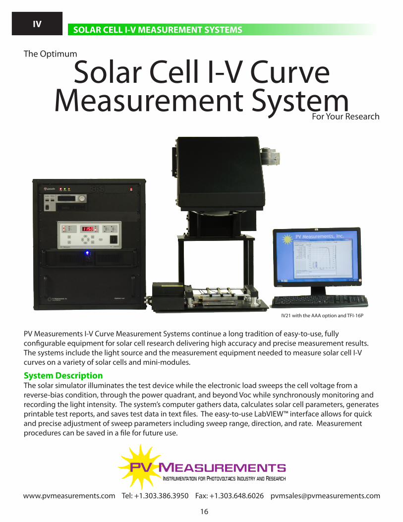
PV Measurements I-V Curve Measurement Systems continue a long tradition of easy-to-use, fully configurable equipment for solar cell research delivering high accuracy and precise measurement results. The systems include the light source and the measurement equipment needed to measure solar cell I-V curves on a variety of solar cells and mini-modules.
System DescriptionThe solar simulator illuminates the test device while the electronic load sweeps the cell voltage from a reverse-bias condition, through the power quadrant, and beyond Voc while synchronously monitoring and recording the light intensity. The system’s computer gathers data, calculates solar cell parameters, generates printable test reports, and saves test data in text files. The easy-to-use LabVIEW™ interface allows for quick and precise adjustment of sweep parameters including sweep range, direction, and rate. Measurement procedures can be saved in a file for future use.
IV21 with the AAA option and TFI-16P
Solar Cell I-V Curve Measurement System
The Optimum
For Your Research
SOLAR CELL I-V MEASUREMENT SYSTEMSIV
www.pvmeasurements.com Tel: +1.303.386.3950 Fax: +1.303.648.6026 [email protected] www.pvmeasurements.com Tel: +1.303.386.3950 Fax: +1.303.648.6026 [email protected]
17
SOLAR CELL I-V MEASUREMENT SYSTEMSIV
Basic System ; Computes solar cell parameters: Voc, Isc, Jsc, Vmax, Imax, Pmax, Rshunt, Rseries, fill factor and efficiency ; 4-wire connection to customer’s test device mounting and contacting fixture ; Computer, LCD monitor, keyboard ; I-V measurement software ; Compensation for light intensity fluctuations ; Measures light and dark I-V characteristics ; ASTM Method E 948-09 compliant ; Automatic solar simulator shutter control ; Instruction manual
Options ; Class-AAA solar simulator instead of Class-ABA ; Additional current and voltage ranges ; Beam-up test fixture for superstrate devices ; Reverse-bias leakage test function ; Provide measurement results to your database ; Setup and training at your site ; Interface with your automated cell-handling equipment ; Vacuum test fixture with temperature control option ; Attenuated light measurement capability for Rseries calculation ; Other options are available; please contact us to discuss your requirements
Irradiance Monitor Measurement CorrectionsXenon light sources inherently have some flicker and all light sources have drift. Therefore, the PV Measurements Solar Cell I-V Curve Measurement Systems, excluding the IV1, measure solar simulator light intensity at the test surface simultaneously with the device signal. The I-V data is then corrected for any lamp fluctuations.
Reverse-Bias TestingIn a real photovoltaic panel, a solar cell may be shaded and therefore reverse biased. To portray how a cell will react to this situation, PV Measurements Solar Cell I-V Curve Measurement Systems offer the optional capability to measure the electrical properties of a dark solar cell under reverse-bias voltage. Options include single voltage or a multi-point sweep.
Busbar-To-Busbar TestingTest the quality of your busbars and gridlines by running a current from one busbar to another. Add this option to your electronic load based Solar Cell I-V Measurement Systems to help identify and diagnose metallization issues.
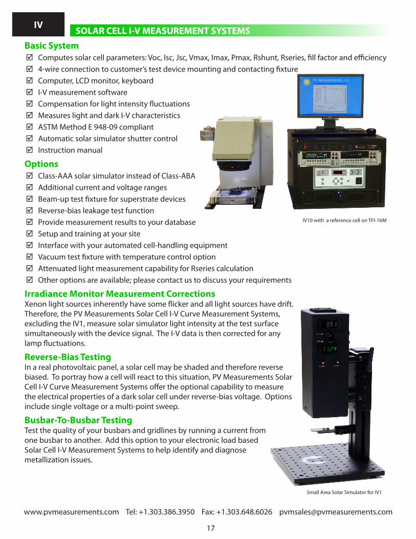
IV10 with a reference cell on TFI-16M
Small Area Solar Simulator for IV1

www.pvmeasurements.com Tel: +1.303.386.3950 Fax: +1.303.648.6026 [email protected]
18
SOLAR CELL I-V MEASUREMENT SYSTEMSIV
www.pvmeasurements.com Tel: +1.303.386.3950 Fax: +1.303.648.6026 [email protected]
Solar SimulatorThe size and type of solar simulator depends on your measurement needs. Please review the specifications below and select the solar simulator that matches your needs.
ModelIV1 IV3 IV5 IV10 IV16 IV21 IV30
Illumation area [mm] 10 38 50 100 160 210 300Uniform area shape Round Square Solar simulator class ASTM E927-05
BBA ABB ABA (Class-AAA optional) AAA
Spectral match to AM1.5G
Class-B Class-A (0.75 - 1.25 at each wavelength band as per AM1.5G)
Temporal instability ± 2 % Class-A
± 5 % Class-B
± 2 % Class-A ± 1 % {L option}
Spatial non-uniformity ± 5 % Class-B ± 5 % Class-B± 2 % (Class-A option) & {L option}
± 2 % Class-A
Working distance [mm] Class-BBAClass-ABA(Class-AAA option){L option}
12051 ± 12
(304 ± 12)76 ± 12
(102 ± 12)102 ± 12
(127 ± 12){610 ± 51}
150 ± 12 (381 ± 12){610 ± 51}
(304 ± 12)
Lamp type Quartz halogen
Xenon arc
Multiple Light Levels for Series Resistance CalculationsSolar Cell I-V Curve Measurement Systems from PV Measurements include the capability of measuring the I-V curve characteristics under no illumination to give an additional estimate of test device series resistance. With the optional dimmer, the I-V systems measure the I-V curve at one or more additional light levels to
give a more accurate estimate.
Continuous Solar Simulator for Increased AccuracyContinuous solar simulators give a test scenario that is more similar to the end use conditions than flash testers since variations in natural solar irradiance are typically on the order of minutes or seconds, rather than milliseconds. The importance of this difference varies from substantial to negligible depending on the response characteristics of the solar cell under test.
Flexible Data ReportingThe system delivers full I-V curves graphically and in tab-delimited text files along with all the calculated I-V parameters. The printable test report includes both the graphical representation of the I-V curve and cell
The software shows I-V curve measurement result at the end of each scan.

www.pvmeasurements.com Tel: +1.303.386.3950 Fax: +1.303.648.6026 [email protected] www.pvmeasurements.com Tel: +1.303.386.3950 Fax: +1.303.648.6026 [email protected]
19
SOLAR CELL I-V MEASUREMENT SYSTEMSIV
parameters. Cell parameters can also be stored in a summary file that gives a quick overview of a series of measurements.
Electronic Measurement SystemPV Measurements offers two basic types of electronic measurement systems, each with multiple options. The first is based on the Keithley 2400 series SourceMeter™ and the second based on the PV Measurements electronic load (E-load). Please review the table below to see which is better for your application.
Electronic Measurement System Keithley SourceMeter Based PV Measurements E-load
1 A 3 A Opt. 5 A Opt.
Irradiance monitor IncludedVoltage ranges ± 2.0 V ± 2.0 V
± 20.0 V ± 10.0 V± 30.0 V ± 30.0 V
Current ranges ± 1 μA± 10 μA ± 1.0 mA
± 100 μA ± 5.0 mA± 1.0 mA ± 20 mA± 10 mA ± 100 mA
± 100 mA ± 400 mA± 1.0 A ± 4.0 A± 3.0 A ± 5.0 A ± 10.0 A
± 20.0 A Measures dark and light I-V characteristics
Included
Computed solar cell parameters Voc, Isc, Jsc, Rseries, Rshunt, Vmax, Imax, Pmax, fill factor and efficiency
Reverse bias leakage test function Optional, contact PV Measurements for details.Reverse bias leakage test, 1 voltage
4 A between -10 and -15 V (Opt.)
Reverse bias leakage test, sweep Included(See current and voltage ranges above)
4 A between -4 and -15 V (Opt.)
Busbar to busbar resistance measurements
0 A to 20 A at 0 V to 2 V (Opt.)
Optional Automation InterfaceThe automation interface allows this measurement system to operate in coordination with the customer’s automated cell handling, placement, and contacting equipment. The interface uses digital signals to detect
when a test is needed and to inform the automation equipment that a test is complete and data is ready. Additional digital outputs are used to inform the automation equipment of an error if one occurs.Spectroradiometer
www.pvmeasurements.com Tel: +1.303.386.3950 Fax: +1.303.648.6026 [email protected]
20
SOLAR CELL I-V MEASUREMENT SYSTEMSIV
www.pvmeasurements.com Tel: +1.303.386.3950 Fax: +1.303.648.6026 [email protected]
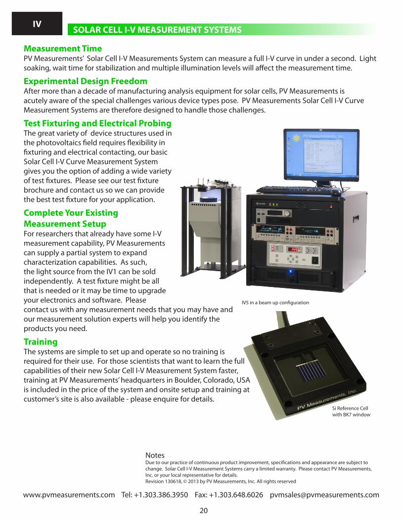
IV5 in a beam up configuration
Measurement TimePV Measurements’ Solar Cell I-V Measurements System can measure a full I-V curve in under a second. Light soaking, wait time for stabilization and multiple illumination levels will affect the measurement time.
Experimental Design FreedomAfter more than a decade of manufacturing analysis equipment for solar cells, PV Measurements is acutely aware of the special challenges various device types pose. PV Measurements Solar Cell I-V Curve Measurement Systems are therefore designed to handle those challenges.
Test Fixturing and Electrical ProbingThe great variety of device structures used in the photovoltaics field requires flexibility in fixturing and electrical contacting, our basic Solar Cell I-V Curve Measurement System gives you the option of adding a wide variety of test fixtures. Please see our test fixture brochure and contact us so we can provide the best test fixture for your application.
Complete Your Existing Measurement SetupFor researchers that already have some I-V measurement capability, PV Measurements can supply a partial system to expand characterization capabilities. As such, the light source from the IV1 can be sold independently. A test fixture might be all that is needed or it may be time to upgrade your electronics and software. Please contact us with any measurement needs that you may have and our measurement solution experts will help you identify the products you need.
TrainingThe systems are simple to set up and operate so no training is required for their use. For those scientists that want to learn the full capabilities of their new Solar Cell I-V Measurement System faster, training at PV Measurements’ headquarters in Boulder, Colorado, USA is included in the price of the system and onsite setup and training at customer’s site is also available - please enquire for details.
NotesDue to our practice of continuous product improvement, specifications and appearance are subject to change. Solar Cell I-V Measurement Systems carry a limited warranty. Please contact PV Measurements, Inc. or your local representative for details. Revision 130618, © 2013 by PV Measurements, Inc. All rights reserved
Si Reference Cell with BK7 window
www.pvmeasurements.com Tel: +1.303.386.3950 Fax: +1.303.648.6026 [email protected] www.pvmeasurements.com Tel: +1.303.386.3950 Fax: +1.303.648.6026 [email protected]
21
Instrumentation for Photovoltaics Industry and Research
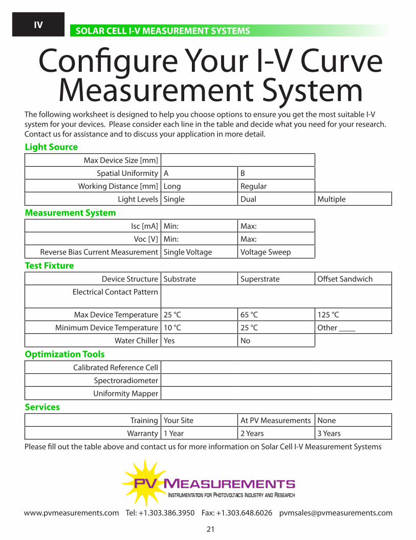
The following worksheet is designed to help you choose options to ensure you get the most suitable I-V system for your devices. Please consider each line in the table and decide what you need for your research. Contact us for assistance and to discuss your application in more detail.
Light SourceMax Device Size [mm]
Spatial Uniformity A B
Working Distance [mm] Long Regular
Light Levels Single Dual Multiple
Measurement SystemIsc [mA] Min: Max:
Voc [V] Min: Max:
Reverse Bias Current Measurement Single Voltage Voltage Sweep
Test FixtureDevice Structure Substrate Superstrate Offset Sandwich
Electrical Contact Pattern
Max Device Temperature 25 °C 65 °C 125 °C
Minimum Device Temperature 10 °C 25 °C Other ____
Water Chiller Yes No
Optimization ToolsCalibrated Reference Cell
Spectroradiometer
Uniformity Mapper
ServicesTraining Your Site At PV Measurements None
Warranty 1 Year 2 Years 3 Years
Please fill out the table above and contact us for more information on Solar Cell I-V Measurement Systems
Configure Your I-V Curve Measurement System
SOLAR CELL I-V MEASUREMENT SYSTEMSIV