the nib - 96 network interface board - fire alarm...
TRANSCRIPT

the NIB - 96Network Interface Board
for the System 500, System 5000, AFP-200, AFP-400and AM2020/AFP1010 Fire Alarm Control Panels
with NIB software P/N 73454 or higher
12 Clintonville RoadNorthford, CT 06472Phone: 203-484-7161Fax: 203-484-7118
Document # 1566610/15/97 Revision D
P/N 15666:D1 ECN 97-407
Technical Manuals Online! - http://www.tech-man.com

Document 15666 Rev. D 9/19/962
Technical Manuals Online! - http://www.tech-man.com

Document 15666 Rev. D 9/19/96 3
Table of Contents
Section One:Introduction ------------------------------------------------------------------ 4
Section Two:The NIB-96 ------------------------------------------------------------------- 6
Section ThreeNetwork Interface Board Description -------------------------------- 13
Section FourSystem 5000 Slave Installation --------------------------------------- 14
Section Five:System 500 Slave Installation ----------------------------------------- 17
Section Six:AM2020/AFP1010 Slave Installation -------------------------------- 20
Section Seven:Slave AM2020/AFP1010 Programming ----------------------------- 23
Section Eight:Master AM2020/AFP1010 Programming --------------------------- 24
Section Nine:Master System 5000 Programming ---------------------------------- 25
Section Ten:AFP-200 Slaves ---------------------------------------------------------- 26
Appendix A:Master System 5000 Considerations -------------------------------- 30
Appendix B:Master AM2020/AFP1010 Considerations ------------------------- 32
Appendix C:Network Requirements for ULC-listed Panels --------------------- 33
Technical Manuals Online! - http://www.tech-man.com

Document 15666 Rev. D 9/19/964
Related DocumentationThis document references installation and programming manuals for the variousfire alarm control panels that can be used with the NIB-96 Network Interface Board.To obtain a complete understanding of specific features of the NIB-96 or to becomefamiliar with functions in general, make use of the documentation listed in Table 1-1 below.
Section One:General Information
Circuit RatingsUnless otherwise stated in this manual, the wiring requirements and specificationscontained in Table 1-2 apply to all references to the LIB SLC Loop and EIA-485circuit.
Title Document
The System 5000 Installation Manual 15583
The System 5000 Programming Manual 15584
The System 5000 Operating Manual 15581
The Voice Alarm System 5000 15890
The System 500 Manual 15019
The AFP-200 Manual 15511
The AFP-400 Installation Manual 50253
The AFP-400 Programming Manual 50259
The AFP-400 Operating Manual 50260
The AM2020/AFP1010 Manual 15088
The AM2020/AFP1010 Voice Alarm Multiplex Manual 15889
The AIM-200 Addressable Intelligent Module Manual 15949
The RPT-485 Repeater Manual 15640
Table 1-1 Related Documentation
Circuit Notes
LIB SLC Loop
Supervised and power limitedMaximum wiring distance: 10,00 feet @12 AWG for LIB-200 12,500 feet @ 12 AWG for LIB-200A/LIB400Maximum loop current: 200mA (short circuit) or 100 mA (normal)Maximum loop resistance: 40 ohms for LIB-200 50 ohms for LIB-200A/LIB400
EIA-485
Supervised and power limited+/- 5 volts peak-to-peakMaximum wiring distance: 4000 feet @ 14 AWGCharacteristic impedance of wiring: 40 ohmsTransmission rate: 2400 baud
Table 1-2 Wiring Specifications
Technical Manuals Online! - http://www.tech-man.com

Document 15666 Rev. D 9/19/96 5
Table 1-3 NIB-96 DIP Switch Settings
Table 1-4 Setting DIP Switches 7 and 8 in a SlaveAM2020/AFP1010 NIB-96
DIP Switch Settings and DescriptionsThe NIB-96 DIP Switch recommended settings contained in Table 1-3 and 1-4apply to the installation procedures for the slave System 5000, System 500,AM2020/AFP1010, AFP-200, and AFP-400.
DIP SwitchAM2020/AFP1010
S5000 S500 AFP-200 AFP-400
1. AUTO ACK ON ON ON ON ON
2. TIMED ACK ON OFF ON OFF OFF
3. AM2020/AFP1010 SLAVE ON OFF OFF OFF OFF
4. NOT USED OFF OFF OFF OFF OFF
5. AM2020/AFP1010 MASTER ON in systems where master panel is AM2020/AFP1010
6. RECEIVE ONLY OFF OFF OFF OFF OFF
7. AM2020/AFP1010 ADDRESS See Table 1-4 OFF OFF OFF OFF
8. AM2020/AFP1010 ADDRESS See Table 1-4 OFF OFF OFF OFF
Slave AM2020/AFP1010 EIA-485 Address
6 & 7 8 & 9 10 &11 12 &13
OFF OFF ON ON
OFF ON OFF ON
Technical Manuals Online! - http://www.tech-man.com

Document 15666 Rev. D 9/19/966
Section Two: The NIB-96
The heart of the NIB Network is the Network Interface Board (NIB). It is a micropro-cessor-controlled module that connects “slave” fire alarm control panels (FACP) toa “master” control panel. The master control panel is an AM2020/AFP1010, AFP-400, or System 5000 with one or more AIM-200 modules. The slave panels can bea mix of AFP-200, AM2020/AFP1010, System 5000, or System 500 panels. TheNIB-96 module is physically located in each slave FACP. Each slave FACP maycontain as many as 96 input/output points or as few as 8 points. Several slave pan-els can be monitored and controlled by a single master. Note: Each NIB networkcan contain only one master FACP.
Slave System 500
Master AM2020/AFP1010
SLC Loop
Slave AM2020/AFP1010
SLC Loop
Notes:1. Up to 10 LIB SLC loops can be installed in a
master AM2020.2. Up to four LIB SLC loops can be installed in a
master AFP1010.3. Each LIB SLC loop can support a maximum of 12
NIB-96 boards (@ 8 points each) or a maximum of96 NIB points.
4. Each NIB may be set to report as few as 8 pointsor as many as 96 points.
5. See the AM2020/AFP1010 Installation Manual,Document 15088 for a detailed configuration andfor connections for transmission to central station.
6. Each slave uses four points for CPU functions.7. Each S5000/S500 slave uses four points for CPU
functions plus four points for CPU output points.8. Wiring from the NIB-96 that goes outside the
building:• cannot exceed 1000 m.• must be in conduit.• cannot cross any power lines.• most not be in the vicinity of any high voltage.
To Remote Station,Municipal Box or CentralStation Receiving System
(see Note 4)
Slave System 5000
Figure 2-1 Network Configuration with Master AM2020/AFP1010
Technical Manuals Online! - http://www.tech-man.com

Document 15666 Rev. D 9/19/96 7
Notes:1. Up to 10 LIB SLC loops can be installed in a master
AM2020 or up to 4 LIB SLC loops in a master AFP1010.2. Each LIB SLC loop can support a maximum of 12 NIB-
96 boards (@ 8 points each) or a maximum of 96 NIBpoints.
3. Each NIB may be set to report as few as 8 points or asmany as 96 points.
4. See Document 15511 for a detailed configuration andfor connections for transmission to central station.
5. Each AFP-200 slave uses eight points for AFP-200system functions. The remaining 88 NIB points can beused in multiples of eight to display the status of AFPzones 1 to 88.
6. The Master can not activate AFP zones.7. The Master can perform the following functions:
Signal Silence via point #2, System Reset via point #3and 'Drill' via point #4 (Drill requires NIB software 73454or higher).
8. The Ground Fault circuit in the AFP-200 must bedisabled by cutting jumper JP9 unless an RPT-485series repeater is used to isolate the AFP-200 from theAM2020/AFP1010 (refer to Document #15640).
Master AM2020/AFP1010
System Common
EIA-485
AFP-200 Slave
ööööö
Figure 2-2 Master AM2020/AFP1010-Slave AFP-200 Configuration(Refer to Table 1-2 for circuit ratings)
Technical Manuals Online! - http://www.tech-man.com

Document 15666 Rev. D 9/19/968
Figure 2-3 Network Configuration with Master System 5000(Refer to Table 1-2 for circuit ratings)
The NIB-96 has two serial interfaces. It communicates with the master panel overthe SLC interface loop, emulating up to 96 MMX and/or CMX modules. It commu-nicates with the slave panel over an EIA-485 annunciator interface, emulating oneor two ACS annunciators (up to 128 LED points, of which only 96 may be used).With the NIB at its maximum, 96 point configuration, each master SLC loop canonly support one slave FACP. With the NIB at its minimum, 8 point configuration,as many as 12 slave FACPs can be supported in one SLC loop. Note that the mas-ter panel can control additional slaves by creating additional SLC loops with the in-stallation of more LIBs or AIM-200s. The capacity of a 10-loop master panel is 960total slave points, less four CPU points for each slave.
To Remote Station orMunicipal Box (see Note 3)
System 5000 (with internalEIA-485 connection between
CPU and NIB-96)
SLC Loop
Notes:1. Up to 10 AIM-200s can be installed in a master System 5000.2. Each AIM-200 can support a maximum of 12 NIB-96 boards
(@ 8 points each) or a maximum of 96 NIB points.3. Each NIB may be set to report as few as 8 points or as many
as 96 points.4. Remote Station, Municipal Box or Central Station receiving unit
connects to the Master System 5000 (refer to Document 15583for details).
5. Manual control of slave output relays and notification circuitsis not possible from the master System 5000.
6. Each slave uses four points for CPU functions.
Master System 5000
SLC Loop
1234123412341234
XPP-1 XPR-8
SLC Loop
Transponder Cabinet
System 500
Technical Manuals Online! - http://www.tech-man.com

Document 15666 Rev. D 9/19/96 9
The System 5000 is a module-based system with eight points reserved for eachmodule position (whether the position is used or not). If a module in a slave Sys-tem 5000 or System 500 employs only four points instead of eight, the remainingfour points are unusable.
For example, Figure 2-4 illustrates the use of three modules with eight initiatingdevice circuits, four notification appliance circuits, and four control relays.
CPU IZM-8 ICM-4 CRE-4
Slave System 5000 (or System 500) Cabinet
Figure 2-4 Point Utilization in Slave Panel
8 points 8 points 4 points 4 points 4 points 4 pointsused used used unused used unused
Requires 32 addresses (switch size=4)
Networked systems may concentrate large systems by grouping many points to-gether in a “software zone” and only reporting alarm or trouble for the softwarezone. This technique allows very large system point capacity. However, a user atthe master FACP may not be able to determine the exact location of a given event.Exact location information is available at the remote FACP.
Since the NIB Network reports slave status as module points and not as detectors,analog information is not available at the master FACP. Analog information is avail-able only at the slave panels. Maintenance Alert and Auto Test error will still reportto the master as a trouble.
The NIB Networks have full control-by-event capability. An alarm at any point onany remote FACP may activate any point(s) on any other slave FACP(s). The mas-ter FACP program contains all instructions to accomplish this. Full Signal Silenceand System Reset capabilities from the master FACP keypad to all slave FACPsare also provided.
Technical Manuals Online! - http://www.tech-man.com

Document 15666 Rev. D 9/19/9610
NFPA Standards - AM2020/AFP1010 Master SystemsWhen installed in accordance with the AM2020/AFP1010 Manual, Document 15088,the AM2020/AFP1010 master control panel meets the requirements of the followingNFPA standards:
NFPA 72-1993 Local Protective Signaling SystemsNFPA 72-1993 Auxiliary Protective Signaling SystemNFPA 72-1993 Remote Station Protective Signaling SystemNFPA 72-1993 Proprietary Signaling System Receiving UnitNFPA 72-1993 Proprietary Signaling System Protected Premises UnitNFPA 72-1993 Central Station Service - Protected Premises UnitNFPA 72-1993 Central Station Receiving Unit
Selection of software and minimum default system configuration is done in accor-dance with the AM2020/AFP1010 Manual. The slave panels (which may be anAM2020, AFP1010, a System 5000, or a System 500) act as data-gathering panelsfor the master AM2020/AFP1010. The alarm/trouble/normal status of each addres-sable device or zone of devices is reported by the slave panel to the master panelfor action. In addition, the slave panels may have notification appliance circuits andcontrol relays which are commanded on or off by the master AM2020/AFP1010. Theslave panels are located within the protected premises. The master panel may belocated remotely.
Wiring Requirements - AM2020/AFP1010 Master PanelSlave panels connect to one or more LIB modules in the AM2020/AFP1010 Master.The wiring requirements to connect to the LIB SLC loop are defined in Document15088.
NFPA Standards - System 5000 Master SystemsWhen installed in accordance with the System 5000 Installation Manual, the System5000/AIM-200 master control panel meets the requirements of the following NFPAstandards:
NFPA 72-1993 Local Protective Signaling SystemsNFPA 71-1993 Central Station Service - Protected Premises unitNFPA 72-1993 Remote Station Protective Signaling SystemNFPA 72-1993 Proprietary Signaling System Protected Premises Unit
Software minimum default programs are done automatically when the System 5000is programmed as described in the System 5000 Programming Manual. The masterSystem 5000 must have at least one AIM-200 module which must be installed andprogrammed as described in the AIM-200 Manual.
Slave panels (which may be System 5000, or System 500) act as data-gatheringpanels for the master System 5000. The alarm/trouble/normal status of each zoneof devices is reported by the slave panel to the master panel for action. In addition,the slave panels may have notification appliance circuits and control relays whichare commanded on or off by the master System 5000. Both the master and all slavepanels must be located within the protected premises of the building complex.
Wiring Requirements - System 5000 Master PanelSlave panels connect to one or more AIM-200 modules in the System 5000 Master.
Technical Manuals Online! - http://www.tech-man.com

Document 15666 Rev. D 9/19/96 11
Wiring Requirements - Networked Voice SystemsThe NIB-96 may be used in voice evacuation systems where an AM2020/AFP1010is the master panel and System 5000 panels are slaves. This configuration pro-vides multiplex voice service similar to XP Transponder voice systems. In themultiplex voice system, the AMG–1 Audio Message Generator, the FFT-7 FireFighter's Telephone and the ACM–16AT speaker selection switches are located inthe master AM2020/AFP1010. The AA-30/AA-30E Audio Amplifier and speaker/telephone circuit modules are located in the System 5000. The speaker/telephonemodules in the System 5000 may be the VCM-4, VCE-4 or DCM-4. See Figure 2-5 for the NIB–96 voice system block diagram.
For detailed connections and requirements for the AM2020/AFP1010 master, re-fer to the AM2020/AFP1010 Voice Alarm Multiplex manual. All connections to theAMG-1, FFT-7, and ACM–16AT modules are identical to those shown in thatmanual.
For detailed connections within each slave System 5000, refer to the Voice AlarmSystem 5000 manual (even though the AMG-1 and FFT-7 are physically located inthe AM2020/AFP1010 master cabinet).
Technical Manuals Online! - http://www.tech-man.com

Document 15666 Rev. D 9/19/9612
Figure 2-5 NIB-96 Voice System Block Diagram(Refer to Table 1-2 for circuit ratings. All connections between panels are
supervised and power limited)
EOL Resistor
Speaker Circuits Telephone Circuits
EOLResistor
To additionalSlave S5000
Audio Loop
SLC Loop To NIB-96
PhoneLoop
To NIB-96
Slave System 5000
Slave System 5000
MasterAM2020/AFP1010
AA-30/E orAA-120/E
AA-30/E orAA-120/E
LIB-200,LIB-200A,or LIB-400
Technical Manuals Online! - http://www.tech-man.com

Document 15666 Rev. D 9/19/96 13
8 7 6 5 4 3 2 1 6 5 4 3 2 1
Earth Ground
Earth Ground
SLC P5 EIA-485 P4
EIA-485Loop OUT
+ -EIA-485Loop IN+- No
Connection
TROUBLE LED (Yellow)Lights during loss of communicationson EIA-485 or SLC loop.
EIA-485 ON-LINE LED (Green)Blinks during communication withthe slave FACP.
SLC ON-LINE LED (Green)Blinks during communicationwith the master FACP.
SLC START ADDRESSSwitchSet to 01 through 99. (Notethat the sum of ADDRESSand SIZE may not exceed 99.)
SLC and EIA-485 ConnectionsAll connections are power-limited andsupervised. See Sections 3, 4 and 5 fordetails on connection requirements. Seediagram below for terminal assignment.
POWER IN connection to Main Power Supply(if not mounted in ICA-4/4L).
POWER OUT connection to other equipment.
NIB POWERREQUIREMENTS: 24VDC power-limitedStandby: 22mAAlarm: 22mA
SLC Loop OUT - shield +
POWER CONNECTOR forthe AM2020/AFP1010 slave.
Note: The EIA-485 circuit requires a serial connection. Connect only one wire toeach screw terminal.
SLCLoop IN - shield +
Section Three:Network Interface Board Description
SIZE Select SwitchSelect number ofpoints monitored on theslave panel. Set to 1through 8. See sizesettings on page 15.
Technical Manuals Online! - http://www.tech-man.com

Document 15666 Rev. D 9/19/9614
Section Four:System 5000 Slave Installation
Mechanical InstallationIn a System 5000 slave, the NIB mounts beneath the third and fourth modules, tothe right of the CPU. The NIB fastens to the base of the CHS-4 chassis using threehex standoffs (provided), which are screwed onto three PEM studs. The NIB is thenattached to the standoffs using the mounting screws provided. See Figure 4-1.
Electrical InstallationConnect the main power harness from the MPS power supply to P3 the NIB. Con-nect the short power harness (provided) from P2 on the NIB to the CPU-5000. SeeFigure 4-2 for wiring diagram and all terminal assignments.
Connect the EIA-485 annunciator signal from the two-terminal connector on thelower CPU board (TB-2) to the NIB EIA-485 IN terminals.
Connect the SLC loop from an AIM-200 module in the master System 5000 to theSLC input terminals. The NIB can support a very large slave System 5000 (88points in addition to the eight points on the CPU) and use almost all of the SLCmodule capacity (96 out of 99 maximum). Alternately, several smaller slave Sys-tem 5000s can be supported by a single multi-drop SLC. For example, six System5000 slaves, each with eight initiating zones, could be monitored and controlled byone SLC.
CHS-4
Step 1 Step 2
NIB-96
NIB CHS-4
Figure 4-1 Mounting the NIB
Technical Manuals Online! - http://www.tech-man.com

Document 15666 Rev. D 9/19/96 15
CPU-5000
Figure 4-2 Wiring the NIB/System 5000 Slave Network(Refer to Table 1-2 for circuit ratings)
SIZE Setting Table(Printed in the lowerleft-hand corner of the NIB-96 board.)
P2MPS-24A/E or
MPS-24B/E
EIA-485 LoopOUT to otherannunciators
(if used)
Main PowerHarness#71086.
Main Power Harness (P/N 75099)
P2
P3
NIB-96
EIA-485 Loop- + TB2
J7
SLC Loop INSLC Loop OUT
Size SettingsThe rotary decimal SIZE switch on the NIB sets the capacity of the System 5000.The size corresponds to the number of slave circuits that the master control panelwill monitor as individual points. The SIZE of the System 5000 is usually eight timesthe number of modules installed, including the CPU.
Note: All connections shown arepower limited
Switch Setting No. of Points
1 8
2 16
3 24
4 32
5 40
6 48
7 56
8 64
9 80
0 96
Terminal Assignments
SLC Loop INFrom: AIM-200 SLC Loop OutTo: NIB-96 P5 terminals 1(+) and 3(-)
EIA-485 Loop INFrom: CPU-5000 TB2 terminals 2(+) and 1(-)To: NIB-96 P4 terminals 5(+) and 3(-)
SLC Loop OutFrom: NIB-96 P5 terminals 5(+) and 7(-)To: Next device on SLC Loop
EIA-485 Loop OUTFrom: NIB-96 P4 terminals 6(+) and 4(-)To: Next device on EIA-485 Loop
Technical Manuals Online! - http://www.tech-man.com

Document 15666 Rev. D 9/19/9616
The total of START ADDRESS and the number of points in the Slave panel minus1 cannot exceed 96.
[(START ADDRESS) + (# of points in SLAVE) - 1] < 96
DIP Switch SettingsRefer to Table 1-3 for switch descriptions and settings.
System 5000 Slave ProgrammingThe programming rules listed below must be followed:
1. SWITCH INHIBIT may not be used.
2. ANNUNCIATOR INSTALL must be set to one of the following positions:
• 1-64 points if the NIB size is set to 64 or less.
• 64-128 points if the NIB size is set to 80 or 96 points.
3. ANNUNCIATOR MODE must be set to “Output Control”
4. Remote annunciators used with the slave System 5000 must be set to Re-ceive-only.
I/O MappingFor I/O mapping of notification circuits and relays as a function of initiating circuits,the System 5000 must be programmed as follows:
1. If the network system is to be controlled by the master control panel, andhave alarms from one slave activate output circuits in a different slave, donot program any I/O map in the slave System 5000. Perform all control-by-event mapping in the Master control panel.
2. If the system does not require that the master control panel activate outputcircuits in the slave panels, then program all I/O mapping into the slaveSystem 5000 and do not program any mapping into the master controlpanel.
Programming of control-by-event mapping into both the master and the slave is notallowed because of the possibility of installer error and program mismatch.
SW2:SIZE Switch
SW3 and SW4:START ADDRESSSwitches
Start Address SettingSet the START ADDRESS switches to the desiredaddress from the master SLC loop. The NIB–96 willassume all module addresses from [START AD-DRESS] to [START ADDRESS + SIZE].
If the master is a System 5000 AIM Module, only ini-tiating devices can be installed above address 59.Addresses 60 and above IZM-8 circuits.
Technical Manuals Online! - http://www.tech-man.com

Document 15666 Rev. D 9/19/96 17
Step 1 Step 2
NIB-96
NIB CAB500
Figure 5-1 Mounting the NIB
NYLON
ALUM.
Section Five:System 500 Slave Installation
Mechanical InstallationIn a System 500 slave, the NIB mounts beneath the third (right-most) module. TheNIB fastens to the back of the box using three hex standoffs (one aluminum and twonylon provided), which are screwed into the three female PEM nuts as shown. TheNIB is then attached to the backbox with the screws provided. See Figure 5-1 .
Electrical InstallationConnect the main power harness from the System 500 power supply to P3 on theNIB. Connect the power harness provided with the NIB from P2 on the NIB to theCPU–500. See Figure 5-2 for wiring diagram and all terminal assignments.
Connect the EIA-485 annunciator signal from the two-terminal connector on thelower CPU board (TB-2) to the NIB EIA-485 IN terminals.
Connect the SLC loop from an AIM-200 module in the master System 5000 to theSLC input terminals. One SLC loop can support six System 500 slaves, each witheight initiating zones, or three System 500s with 16 initiating zones.
Technical Manuals Online! - http://www.tech-man.com

Document 15666 Rev. D 9/19/9618
Figure 5-2 Wiring the NIB/System 500 network(Refer to Table 1-2 for circuit ratings)
SW2:SIZE Switch
SW3 and SW:START ADDRESSSwitches
MPS-24BPCA
P2
Main Power Harness#75099.
NIB-96
CPU-500- + TB2
EIA-485 Loop
EIA-485 Loop OUT
Main Power Harness
SLC Loop from AIM-200 in System 500
Size SettingsSet the rotary decimal SIZE switch on the NIB to the capacity of the System 500.The SIZE of the System 500 can be 8 (eight CPU points only), 16 (eight CPU pointsand eight zones) or 24 (eight CPU points and 16 zones). Normally the SIZE switchis set to 1,2 or 3. However, if the master panel mustcontrol the output of IC-4L/ICR-4L modules, theSIZE switch should be set to 6 (one IC-4L/ICR-4Lusing points 41-44) or 7 (two IC-4L/ICR-4L usingpoints 41-44 and 49-52). Note that setting theSIZE switch to 6 or 7 will result in a substantialloss of usable system point capacity since severalintermediate points (i.e. 25 to 40) are lost.
Note: All connections shown arepower-limited
Terminal Assignments
SLC Loop INFrom: AIM-200 SLC Loop OutTo: NIB-96 P5 terminals 1(+) and 3(-)
EIA-485 Loop INFrom: CPU-5000 TB2 terminals 2(+) and 1(-)To: NIB-96 P4 terminals 5(+) and 3(-)
SLC Loop OutFrom: NIB-96 P5 terminals 5(+) and 7(-)To: Next device on SLC Loop
EIA-485 Loop OUTFrom: NIB-96 P4 terminals 6(+) and 4(-)To: Next device on EIA-485 Loop
Technical Manuals Online! - http://www.tech-man.com

Document 15666 Rev. D 9/19/96 19
Start Address SettingsThe START ADDRESS switches are set for the desired address from the masterSLC loop. The NIB will answer all module addresses from START ADDRESS to(START ADDRESS + SIZE).
The total of START ADDRESS plus SIZE MINUS 1 must be 96 or less for theNIB to operate.
(START ADDRESS) + (SIZE-1) < 96
DIP Switch SettingsRefer to Table 1-3 for switch descriptions and recommended settings.
System 500 ProgrammingThe programming rules listed below must be followed:
1. ANNUNCIATOR INSTALL must be enabled.
2. Remote annunciators may be connected to the slave System 500 if theyare set to Receive-only.
I/O MappingFor I/O mapping of notification circuits and relays as a function of initiating circuits,the System 500 must be programmed as follows:
1. If the network system is to be controlled by the master control panel, andhave alarms from one slave activate output circuits in a different slave, donot program any I/O map in the slave System 500. Perform all control-by-event mapping in the Master control panel.
2. If the system does not require that the master control panel activate outputcircuits in the slave panels, then program all I/O mapping into the slaveSystem 500 and do not program any mapping into the master control panel.This method is recommended for all System 500 installations containingan IC-4L or ICR-4L module.
Programming of control-by-event mapping into both the master and the slave is notallowed because of the possibility of installer error and program mismatch.
Technical Manuals Online! - http://www.tech-man.com

Document 15666 Rev. D 9/19/9620
Section Six: AM2020/AFP1010 Slave Installation
Mechanical InstallationIn an AM2020/AFP1010 slave, the NIB may be plugged into a slot on the ICA-4/4Lchassis. If the AM2020/AFP1010 is in an A-size cabinet (only one ICA-4/4L) theNIB mounts beneath the CPU or the SIB. If a second or third ICA-4/4L chassis isavailable, it is recommended that the NIB should be mounted in one of the twoupper slots to permit easy access to NIB wiring and switch settings. Note that theNIB mechanically eliminates one LIB position and, in some instances, could requirethe installation of an additional chassis. As an alternative, the AM2020/AFP1010may use a CHS-4 chassis to mount the NIB. See Figure 4-1 for mounting the NIBin a CHS-4 chassis.
Note also that the AM2020/AFP1010 does not require that LIB boards be installedin consecutive positions. For example, in a 5-loop system, the NIB could be in-stalled in LIB position 3 (upper left of second chassis), with LIBs in all other slots. Inthis case, the AM2020/AFP1010 would be programmed for loops 1, 2, 4, 5, and 6.
In some slave AM2020/AFP1010 applications, it may be necessary to install morethan one NIB. The NIB can be configured so that up to 4 may be installed, com-pletely filling an ICA-4/4L chassis.
or
Figure 6-1 Mounting the NIB in an ICA-4/4L Chassis
Technical Manuals Online! - http://www.tech-man.com

Document 15666 Rev. D 9/19/96 21
SLC Loop IN(To MasterFACP LIB)
SLC Loop OUT
Slave SIB-2048A/SIB-NET
No connection onP2 or P3 if ICA-4/4Lchassis is used.
Term. 5 (+)
Term. 6 (-)
P2 P3
NIB-96
EIA-485 Loop OUTTo additional EIA-485 devices, if installed.
Figure 6-2 Wiring the NIB/AM2020/AFP1010 Network(Refer to Table 1-2 for circuit ratings.)
EIA-485 LoopIN
Electrical InstallationIf the NIB is mounted to a CHS-4 . . .Connect the main power harness from the MPS power supply to P3 on the NIB. Con-nect the short power harness (provided) from P2 on the NIB to the ICA-4/4L. If addi-tional NIBs are installed, the power harness is “daisy-chained” through all NIBs.
If the NIB is mounted to an ICA-4/4L . . .All power connections are completed through the ICA-4/4L connection.
Connect the EIA-485 input to the NIB from the EIA-485 connector on the slave SIB-2048A or SIB-NET. If more than one NIB is installed, or if the slave AM2020/AFP1010 also has annunciators, the EIA-485 OUT terminals on the NIB are used todaisy-chain to these additional EIA–485 devices.
Connect the LIB SLC loop from the master AM2020/AFP1010 to the LIB SLC inputterminals. Typically, each NIB is connected to a single LIB in the master AM2020/AFP1010 and uses almost all of the module capacity (96 out of 99 maximum) of thatLIB SLC.
Technical Manuals Online! - http://www.tech-man.com

Document 15666 Rev. D 9/19/9622
though the AM2020/AFP1010 may have up to1,980 points, a NIB can only report 96 points. Upto 4 NIB’s may be installed in one slave AM2020/AFP1010, allowing a maximum monitor and con-trol capacity of 384 points. Each slave panel uses4 points for CPU functions. There are several soft-ware techniques available to condense the pointreports of the slave AM2020/AFP1010, so thatlarger systems may be accommodated (SeeSlave Programming).
Size SettingsThe rotary decimal SIZE switch on the NIB is set to the number of points that arereported from this slave AM2020/AFP1010 to the master AM2020/AFP1010. Al-
SW2:SIZE Switch
SW3 and SW4:START ADDRESSSwitches
Start Address SettingsThe START ADDRESS switches are set for the desired address from the masterSLC loop. The NIB will answer all module addresses from (START ADDRESS) to(START ADDRESS + SIZE -1) inclusive.
Note that the total of START ADDRESS + SIZE - 1 must be 96 or less for the NIBto operate.
START ADDRESS + SIZE - 1 < 96
DIP Switch SettingsRefer to Tables 1-3 and 1-4 for the recommended AM2020/AFP1010 slave DIPswitch settings.
Terminal Assignments
SLC Loop INFrom: Master LIB (LIB-200 P2 terminals 1(+) and 3(-), LIB-200A TB1terminals 1(+) and 3 (-), LIB-400 TB1 or TB2 terminals 1(+) and 3(-))To: NIB-96 P5 terminals 1(+) and 3(-)
EIA-485 Loop INFrom: SIB-2048A/SIB-NET P5 terminals 3(+) and 4(-)To: NIB-96 P4 terminals 5(+) and 3(-)
SLC Loop OutFrom: NIB-96 P5 terminals 5(+) and 7(-)To: Next device on SLC Loop
EIA-485 Loop OUTFrom: NIB-96 P4 terminals 6(+) and 4(-)To: Next device on EIA-485 Loop
Technical Manuals Online! - http://www.tech-man.com

Document 15666 Rev. D 9/19/96 23
Section Seven:Slave AM2020/AFP1010 Programming
For I/O mapping of notification circuits and relays as a function of initiating circuits,the AM2020/AFP1010 must be programmed as follows:
1. If the network system is to be controlled by the master control panel, andhave alarms from one slave activate output circuits in a different slave, donot program any I/O map in the slave. Perform all control-by-event map-ping in the master control panel.
2. If the system does not require that the master control panel activate outputcircuits in the slave panels, then program all I/O mapping into the slave anddo not program any mapping into the master control panel.
Programming of control-by-event mapping into both the master and the slave is notallowed because of the possibility of installer error and program mismatch.
Communications with the NIB is through the EIA-485 interface. The NIB appears tothe slave as one or two standard annunciators. The AM2020/AFP1010 may sup-port up to 32 annunciator addresses and therefore the NIB may coexist with sev-eral other NIBs, ACS annunciators, etc. The slave program must assign annuncia-tor points to each point on the NIB. These NIB points appear to the slave as an-nunciator points. Commands from the NIB to activate slave relays appear to comefrom ACM-16AT switch activations.
The slave may condense several monitor points into one annunciator point to com-municate with the NIB. For example, several intelligent smoke detectors could beassigned to annunciator point A06P17. The NIB would report the ALARM/TROU-BLE/NORMAL status of this group of smoke detectors to the master AM2020/AFP1010 as a single monitor module with an address 17 higher than the start ad-dress minus one.
Alternately, the slave could condense monitor points by using one of the 240 avail-able software zones, and assigning a NIB annunciator point to that zone. Either ofthese techniques allows the master AM2020/AFP1010 to monitor large slave in-stallations using a relatively small number of points. When these condensationtechniques are used, definition of the exact detector or module in alarm or troubleis not available at the master, but is still available at the slave. Control relays on theslave should not be grouped. When programming the slave AM2020/AFP1010, oneNIB annunciator point must be allocated for each slave control point.
• Select and disable all NFPA selections in software.• NIB point 1 is reserved for ACKNOWLEDGE input to the slave and system
troubles report to the master.• NIB point 2 is used for signal silence in AFP-200, S500 and S5000 slaves.• NIB point 3 is reserved for SYSTEM RESET input to the slave.• NIB point 4 is used to activate signals in the AFP-200.• Program all slave points to the annunciator points of the NIB address.
Technical Manuals Online! - http://www.tech-man.com

Document 15666 Rev. D 9/19/9624
Section Eight: Master AM2020/AFP1010 Programming
All points in the slave panels are programmed into the master AM2020/AFP1010 asmonitor or control modules. Software features are programmed for the slave pointsas if these points were MMX-1 or CMX-1 devices. The following are programmingguidelines which must be followed:
• Program the first point in every NIB (slave) into the master AM2020/AFP1010as a Monitor Point (MON). This point will annunciate any trouble in the slave andis used as a default slave alarm reporting point in event of a programming errorin the slave. Control-by-event for this point will be activated only if an alarm ispresent in the slave panel which falls outside of the NIB size and there is no otheractive point present within the range of the NIB. Program the Control-by-eventfor this point appropriately. Do not rely on the operation of this point for alarmreporting. Program the system properly.
• Point 2 is used for Signal Silence in AFP-200 and System 500 and 5000 slaves.Program this point as "CON" in the master AM2020/AFP1010. Design the Con-trol-by-event equation for this NIB point so that it is active (ON) whenever noti-fication appliances are activated in the slave. When programming this point inthe AM2020/AFP1010, enable the signal silence feature for Point 2 in the mas-ter. All notification appliances in the slave must be outside the range of the NIBin order to utilize this feature. If not outside the NIB range, do not program point2 in the master. Normal operation of this feature indicates an alarm in the slave,and that alarm is silenceable from the master. If the alarm is silenced from theslave, an "open circuit" condition will occur at the master for NIB point 2. Note:Every zone in the slave must be mapped back to the master or this featureshould not be used.
• Point 3 is used for system reset in the slave and must be programmed in themaster as a 'CON' with a null () Control-by-event equation.
• Point 4 activates all silenceable signals in the AFP-200 slave only. Program thispoint as "CON" in the master. This point should also be programmed assilenceable. Design the Control-by-event equation for this NIB point so that it isactive when you want to turn on silenceable signals. This control point may bemapped to an ACM-16AT annunciator point in the master which will serve as adrill or evacuation switch.
• Initiating and input devices (including groups of devices or zones) from the slavepanel should be given any appropriate monitor module type ID (see the AM2020/AFP1010 Manual for software type ID listings) in the master.
• Notification circuits (e.g. ICM-4 module points) in the slave panels should be giv-en any appropriate type ID for a supervised control module in the master.
• Relays (e.g. CRM-4 relays) in the slave should be given any appropriate type IDfor a supervised (not Form-C) control module in the master.
• Program all slave speaker circuits as 'SPKR' type ID in the master.
• Program all slave telephone circuits as 'TELE' type ID in the master.
• Signal Silence option must be selected in the slave for all slave control pointsthat are to be silenced from the master.
Technical Manuals Online! - http://www.tech-man.com

Document 15666 Rev. D 9/19/96 25
• Latching (non-tracking) should be used for initiating devices.
• If Control-by-event of the slave outputs is to be performed by the slave FACP,then do not map the slave control points into the NIB.
Section Nine: System 5000 Master ProgrammingThe System 5000 may only be a master controller in the network if it includes oneor more AIM-200 modules. Typically, the System 5000 master would be used tomonitor and control slave System 500 panels.
No change is made to the System 5000 or the AIM-200 module to support NIB mod-ules. The AIM-200 is programmed to perform all functions as if the slave points wereMMX–1 and CMX–1 modules. The AIM-200 auto-program function will performmost of the programming actions. The following are recommendations for programediting:
• The first point on each slave panel should be programmed as a generalalarm monitor point. This is used for system troubles from the slave or fordefault alarm reporting in case of a programming error in the slave.
• Points 2, 3 and 4 on a slave will auto-program as “C” modules. The ad-dresses may not be used for other MMX–1 or CMX–1 standard modules.
• Output points that are to be silenced from the master should be programmedas signal type “C (blank).”
• Output points that are not to be silenced from the master should be pro-grammed as Form-C type “CO.”
• Zone mapping (control-by-event) must be selected to perform the desiredsystem control functions. Note that a particular AIM-200 cannot performcontrol-by-event for zones outside that AIM-200 except for general alarmtype action.
• If the slave panels are to be programmed for control-by-event mapping, thenprogram the master AIM-200 to skip all “C” modules (no control-by-event).Trouble on these modules will only be reported as system trouble from theslaves.
• General alarm programming of control points is not possible on the AIM-200for points above address 60. If general alarm programming is necessary, theSystem 5000/AIM-200 should not use slave panels that have control pointsabove address 60.
• Zones on the AIM-200 must be programmed for SWITCH INHIBIT and NON-SILENCEABLE.
CAUTION: Do not select the extended programming features. The System 5000may not operate properly if the Auto Silence, Pre-Signal Delay or General AlarmDrill Switch features are selected.
Technical Manuals Online! - http://www.tech-man.com
Document 15666 Rev. D 9/19/9626
or
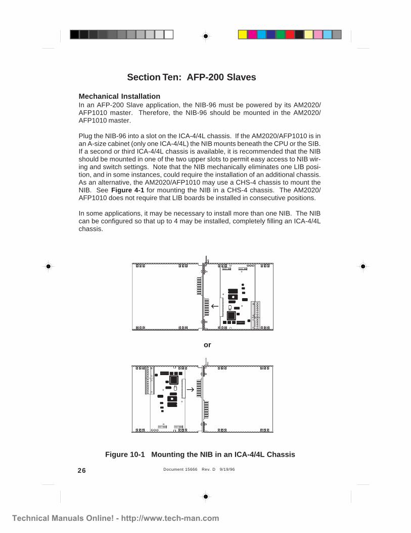
Section Ten: AFP-200 Slaves
Mechanical InstallationIn an AFP-200 Slave application, the NIB-96 must be powered by its AM2020/AFP1010 master. Therefore, the NIB-96 should be mounted in the AM2020/AFP1010 master.
Plug the NIB-96 into a slot on the ICA-4/4L chassis. If the AM2020/AFP1010 is inan A-size cabinet (only one ICA-4/4L) the NIB mounts beneath the CPU or the SIB.If a second or third ICA-4/4L chassis is available, it is recommended that the NIBshould be mounted in one of the two upper slots to permit easy access to NIB wir-ing and switch settings. Note that the NIB mechanically eliminates one LIB posi-tion, and in some instances, could require the installation of an additional chassis.As an alternative, the AM2020/AFP1010 may use a CHS-4 chassis to mount theNIB. See Figure 4-1 for mounting the NIB in a CHS-4 chassis. The AM2020/AFP1010 does not require that LIB boards be installed in consecutive positions.
In some applications, it may be necessary to install more than one NIB. The NIBcan be configured so that up to 4 may be installed, completely filling an ICA-4/4Lchassis.
Figure 10-1 Mounting the NIB in an ICA-4/4L Chassis
Technical Manuals Online! - http://www.tech-man.com

Document 15666 Rev. D 9/19/96 27
No connection onP2 or P3 if ICA-4/4Lchassis is used.P2 P3
NIB-96
Electrical InstallationIf the NIB is mounted to a CHS-4...Connect the main power harness from the MPS power supply to P3 on the NIB.Connect the short power harness (provided) from P2 on the NIB to the ICA-4/4L Ifadditional NIBs are installed, the power harness is daisy-chained through all NIBs.
If the NIB is mounted to an ICA-4/4L...All power connections are completed through the ICA-4/4L connection.
Referring to the terminal assignment table below, connect the EIA-485 input on theNIB to the EIA-485 connector on the slave AFP-200. If the slave AFP-200 also hasannunciators, the EIA-485 OUT terminals on the NIB are used to daisy-chain tothese additional EIA-485 devices.
Connect the LIB SLC loop from the master AM2020/AFP1010 to the NIB's SLC in-put terminals. Typically, each NIB is connected to a single LIB in the masterAM2020/AFP1010 and uses almost all of the module capacity (96 out of 99 maxi-mum) of that LIB SLC.
Figure 10-2 Wiring the NIB/AM2020/AFP1010/AFP-200 Network
SLC loopOut
SLC loop IN
EIA-485 Loop OUTTo additional EIA-485 devices, if installed.
EIA-485 Loopto AFP-200TB5-1 (+)
TB5-2 (-)
EIA-485
Loop IN
Terminal Assignments
SLC Loop IN
From: Master LIB (LIB-200 P2 terminals 1(+) and 3(-), LIB-200A TB1terminals 1(+) and 3 (-), LIB-400 TB1 or TB2 terminals 1(+) and 3(-))To: NIB-96 P5 terminals 1(+) and 3(-)
EIA-485 Loop INFrom: AFP-200 TB5 terminals 1(+) and 2(-)To: NIB-96 P4 terminals 5(+) and 3(-)
SLC Loop OutFrom: NIB-96 P5 terminals 5(+) and 7(-)To: Next device on SLC Loop
EIA-485 Loop OUTFrom: NIB-96 P4 terminals 6(+) and 4(-)To: Next device on EIA-485 Loop
Technical Manuals Online! - http://www.tech-man.com

Document 15666 Rev. D 9/19/9628
Size SettingsThe setting of the rotary decimal SIZE switch on the NIB determines the number ofAFP-200 zones that will be reported to the Master AM2020/AFP1010. Use Table10-1 to determine the required setting for the SIZE switch.
SW2:SIZE Switch
SW3 and SW4:START ADDRESSSwitches
Table 10-1 SIZE Switch Settings
Start Address Settings The START ADDRESS switches are set for the desired address from the masterSLC loop. The NIB will answer all module addresses from (START ADDRESS) to(START ADDRESS + SIZE -1) inclusive.
Note that the total of START ADDRESS + SIZE - 1 must be 96 or less for the NIBto operate.
START ADDRESS + SIZE - 1 < 96
DIP Switch SettingsRefer to Table 1-3 for the recommended AFP-200 slave DIP switch settings.
Switch
SettingInformation Sent to Master
Size
(Points)
1 System Status 8
2 System Status plus Zones 1 to 18 16
3 System Status plus Zones 1 to 16 24
4 System Status plus Zones 1 to 24 32
5 System Status plus Zones 1 to 32 40
6 System Status plus Zones 1 to 40 48
7 System Status plus Zones 1 to 48 56
8 System Status plus Zones 1 to 56 64
9 System Status plus Zones 1 to 72 80
0 System Status plus Zones 1 to 88 96
Technical Manuals Online! - http://www.tech-man.com

Document 15666 Rev. D 9/19/96 29
General Considerations for slave AFP-200 Panels
1. Program the AFP-200 for 'ANNUN=ACS(ADDR1)' if NIB SIZE is 8 or less. Pro-gram the AFP-200 for 'ANNUN=ACS(ADDR2)' if NIB SIZE is 9 or 0.
2. Set switch SW2 on AFP-200 for ACS mode.
3. The NIB-96 must be powered by the AM2020/AFP1010.
4. The system Common (-) terminal on the AFP-200 must be connected to thesystem Common (-) terminal on the AM2020/AFP1010 Power Supply unlessan RPT-485 series repeater is used (see note 8).
5. Each AFP-200 slave uses eight points for AFP-200 system functions. The re-maining 88 NIB points can be used, in multiples of eight, to display the status ofAFP zones 1 to 88.
6. The Master cannot activate AFP zones.
7. The Master can perform the following functions: Signal Silence via point #2,System Reset via point #3 and 'Drill' via point #4. (Drill requires NIB software73454 or higher).
8. The Ground Fault circuit in the AFP-200 must be disabled by cutting jumperJP9 unless an RPT-485 series repeater is used to isolate the AFP-200 fromthe AM2020/AFP1010. Refer to Document #15640 for more information.
Technical Manuals Online! - http://www.tech-man.com

Document 15666 Rev. D 9/19/9630
CPU
AIM-200
Master System 5000 Cabinet
Alarm Bus cable(Part Number 71033)
To First AIM-200
13 14 15 16 17 18 19 20
Appendix A: Master System 5000 Considerations
Figure A-1 Alarm Bus Cable Installation
NIB-96 Software Changes with System 5000 MasterThe NIB will report an alarm on the first AIM-200 SLC loop address only if thereexists an alarm condition in the slave which falls outside of the NIB size range (in-dicates improper setting). No alarm is reported at the first SLC loop address whenan alarm is present in the slave within the switch selected NIB size range.
Alarm Bus Cable InstallationCaution: Do not connect any other device or circuit to the alarm relay contacts onthe CPU-5000 while this cable is installed in the system. See Figure A-1.
Networking Slaves on the EIA-485 CircuitThe NIB-96 may be located in the master cabinet and communicate to the slaveusing the EIA-485 interface. See Figure A-2 for an example of this configuration.
FromCPU-5000
To NextAIM-200
Technical Manuals Online! - http://www.tech-man.com

Document 15666 Rev. D 9/19/96 31
Figure A-2 Networking Slaves on the EIA-485 Circuit
CPU
CPU
Slave System 5000
Slave System 500
Master System 5000
SLC Loop
SLC Loop
SLC Loop
SLC Loop
EIA-485
EIA-485
EIA-485
EIA-485
EIA-485
NIB-96NIB-96
NIB-96NIB-96
AIM-200
Slave System 5000
CPU
Slave System 500
CPU
EIA-485
Notes:1. All external (EIA-485) wiring is supervised and power-limited.2. Connect main power harness (daisy-chain) through each NIB as shown in Figure 4-2.3. Connect a 14 AWG wire between the system common of each slave power supply to the
system common of the master power supply.
Technical Manuals Online! - http://www.tech-man.com

Document 15666 Rev. D 9/19/9632
Appendix B: Master AM2020/AFP1010 Considerations
NIB-96 Software Changes with Master AM2020/AFP1010The NIB will detect an invalid polling scheme if one or more of the following condi-tions exists:
NIB software P/N 73359 or lower
1. Communication at the two restricted NIB SLC loop addresses (someonehas programmed point 2 or 4, or both).
2. No communication for more than 60 seconds at one or more of the NIBSLC loop addresses (except those restricted above) defined by the NIBsize switch.
NIB software P/N 73454 or higher
The NIB will detect an error if there is no communication for more than 60seconds with one or more of the NIB points 1, 3, 4 or 5 through NIB SIZEfrom the master SLC loop.
If the conditions above are detected, the AM2020/AFP1010 will enter the troublemode and display 'TROUBL LIB XX NIB M/S PROGRAMMING ERROR' or theequivalent.
When excessive noise is detected on the LIB SLC loop connection to the LIB, theAM2020/AFP1010 will enter the trouble mode and display 'TROUBL LIB XX NIBCOMMUNICATION ERROR' or the equivalent.
Technical Manuals Online! - http://www.tech-man.com

Document 15666 Rev. D 9/19/96 33
Appendix C:Network Requirements for ULC listed Panels
NIB-96 network installations requiring Underwriter's Laboratories ofCanada listing must follow the guidelines set forth in this appendix.
In Canada, slave control panels must be able to function as stand-alone units dur-ing loss of communications with the master control panel. Therefore, each slavepanel must be programmed for complete local input/output operation.
If the master control panel is to also control output circuits in the slave panels, caremust be taken to ensure that programming in both the master and the slave(s) isidentical.
Technical Manuals Online! - http://www.tech-man.com

Document 15666 Rev. D 9/19/9634
Technical Manuals Online! - http://www.tech-man.com

Document 15666 Rev. D 9/19/96 35
Technical Manuals Online! - http://www.tech-man.com