the new standard of ultra-compact plcs
TRANSCRIPT

Programmable ControllerSERIESFP0R SERIES
X0X1X2X3X4X5X6X7
COM
Y0Y1Y2Y3
COMY4
COMY5
COM
X0X1X2X3
(NC)(NC)(NC)(NC)COM
Y0Y1Y2Y3
(NC)(NC)(NC)(NC)COM
Y0Y1Y2Y3Y4Y5Y6Y7
COM
C10RS/C10RM C14RS/C14RM E8RS/E8RM E16RS/E16RM/E8YRS
Y0Y1
(NC)(NC)COMY2
COMY3
COM
X0X1X2X3X4X5
(NC)(NC)COM
X0X1X2X3X4X5X6X7
COM
<Reference measuring for wiring> Terminal array
X 0 X 1X 2 X 3X 4 X 5X 6 X 7
COM COM
Input (8 points / common)
Y 0 Y 1Y 2 Y 3Y 4 Y 5Y 6 Y 7(+) (–)
Output (8 points / common)
SGRD
SD
<Reference measuring for wiring> Terminal array
Note: Two COM terminals on the input circuit are connected inside the unit.
RS232C port Terminal array
E−
+
RS485 port Terminal array
X 0 X 1X 2 X 3X 4 X 5X 6 X 7
COM COM
Input (16 points / common)
Y 0 Y 1Y 2 Y 3Y 4 Y 5Y 6 Y 7(+) (–)
Output (16 points / common)
X 8 X 9X A X BX C X DX E X F
COM COM
Y 8 Y 9YA Y BY C Y DY E Y F(+) (–)
SGRD
SD
<Reference measuring for wiring> Terminal array RS232C port Terminal array
E−
+
RS485 port Terminal array
<Reference measuring for wiring> <Reference measuring for wiring><Reference measuring for wiring> <Reference measuring for wiring>
(0.71) 2.36(18) 60.0
(9) (0.35) (0.30)
(7.5)
90.03.54
(Note 1)
DIN standard rail(DIN EN50022 35 mm 1.38 in width)
Front view
60.0
(67.5)
A + B + C + D dimensions (mm in)A A→B A→C A→D
30.01.182.36
(Note 2)
90.03.54
Input connector
Output connector
0.1460.03.5
RS232C port (C32C, T32C and F32C only)RS485 port (C32M, T32M, F32M only)
0.9825.0
Input connector
Output connector
RS232C port (C16C only)RS485 port (C16M only)
(Note 1)
DIN standard rail(DIN EN50022 35 mm 1.38 in width)
(0.39)(10)
DIN standard rail(DIN EN50022 35 mm 1.38 in width)
(Note 1)
Input terminal block
Output terminal block
RS232C port (C10CR and C14CR only)RS485 port (C10MR and C14MR only)
0.98
MODE
OFF ON
V 0
INI 0
COM
COM
FP0
- A21
OUT
V 1I 1
VI
12345
EXPANSIONCONNECTOR
2.36(0.39)25.0 60.0(10)
Notes: 1) DIN rail is attached on the center of the unit. 2) The AFP0RE8YRS is not equipped with an input terminal block.
Notes: 1) DIN rail is attached on the center of the unit. 2) The AFP0RE32T, AFP0RE32P, AFP0RE16X, AFP0RE16YT and AFP0RE16YP are
25 mm 0.98 in each. 3) The AFP0RE16X has no output connector. 4) The AFP0RE16YT and AFP0RE16YP has no input connector.
Notes: 1) Four COM terminals on the input circuit are connected inside the unit.
2) Two (+) terminals and two (-) terminals on the output circuit are connected respectively inside the unit.
Notes: 1) DIN rail is attached on the center of the unit. 2) The AFP0RE8X has no output connector. 3) The AFP0RE8YT and AFP0RE8YP has no input connector.
ERROR
RUN
PROG
ALARM
RUN
P ROG.
01
23
45
67
89
AB
CD
EF
01
23
45
67
89
AB
CD
EF
X8-FXO-7
01
23
45
67
89
AB
CD
EF
01
23
45
67
89
AB
CD
EF
X8-FXO-7
01
23
45
67
89
AB
CD
EF
01
23
45
67
89
AB
CD
EF
X8-FXO-7
01
23
45
67
89
AB
CD
EF
01
23
45
67
89
AB
CD
EF
X8-FXO-7
Y8-FYO-7 Y8-FYO-7 Y8-FYO-7 Y8-FYO-7
90.0
B C DA
(45)
(45)
2.36
(2.66)
3.54
(1.77)
(1.77)
Top view (with DIN rail attached)
C10RSC10CRSC10RMC10CRMC10MRSC14RSC14CRSC14RMC14CRMC14MRS
C32TC32CTC32PC32CPT32CTT32CPF32CTF32CP
C16TC16CTC16PC16CPC16MTC16MP
C32MTC32MPT32MTT32MPF32MTF32MP
Control unit 1 expansion unit connected
Control unit only
2 expansion units connected
3 expansion units connected
(0.18)(4.5)
(10)(0.39) 13.0
0.51
5.12130.0
approx.
5.12130.0
approx.
5.12130.0
approx.
Inpu
tO
utpu
t
Inputterminal
Connection terminalOutputterminal
0.98 1.97 2.95 3.94
1.18 2.17 3.15 4.13
25 50 75 100
30 55 80 105
90.03.54
0.9825
(0.39)(10)
2.3660.0
0.143.5
0.184.5
90.03.54
0.9825.0
0.338.50
2.3660.0
90.03.54
0.143.5
0.184.5
1.3835.0
0.7619.2
2.3660.0
0.143.5
90.03.54
0.143.5
2.3660.0
90.03.54
(0.71)(18)
2.3660.0
90.03.54
(0.18)(4.5)
(0.30) (7.5)
13.00.51
(10)(0.39)
(9) (0.35)
0.143.5
2.3660.0
0.9825.0
90.03.54
2.3660.0
90.03.54
(0.18)(4.5)
(0.30) (7.5)
13.00.51
(10)(0.39)
(9) (0.35)
DIMENSIONS Control units and Expansion units
Control units
Expansion units
FP Web-Server 2 Unit FP0 Power Supply Unit
External Dimensions During Expansions
FP0 Analog I/O Unit and D/A Converter Unit
FP0 A/D Converter Unit and Thermocouple Unit
(Unit: mm in)
* For the relay output type, the terminal block type is listed as the representative type.
C10RS, C10RM, C10CRS, C10CRM, C10MRS,C14RS, C14RM, C14CRS, C14CRM and C14MRS
E8RS, E8RM, E8YRS, E16RS and E16RM
Control units
Expansion units
C16T, C16P, C16CT, C16CP, C16MT and C16MP
E16T, E16P, E8X, E8YT and E8YP
Control units
Expansion units
C32T, C32CT, C32P, C32CP, C32MT, C32MP,T32CT, T32CP, T32MT, T32MP,F32CT, F32CP, F32MT and F32MP
E32T, E32P, E16X, E16YT and E16YP
Recognition(Some models only)Conforming to EMC Directive Listing
(Some models only)
The New Standard of Ultra-compact PLCs
*1. Among compact PLCs with up to 128 I/O points based on our research as of July 1, 2011*2. Based on our research as of July 1, 2011
Equipped with RS485 Port
Multi-axis Control available without Expansion
NEW
Large Capacity Program and Data Memory
Largest in its class *1
Ultra-high Speed ProcessingFastest in its class *1
Battery-less Automatic Backup of All Data
Industry’s First *2
2011.08 panasonic-electric-works.net/sunx
Panasonic Electric Works SUNX Co., Ltd.Global Sales & Marketing Division
2431-1 Ushiyama-cho, Kasugai-shi, Aichi, 486-0901, JapanTelephone: +81-568-33-7861 Facsimile: +81-568-33-8591
All Rights Reserved ©Panasonic Electric Works SUNX Co., Ltd. 2011
2011.08 panasonic-electric-works.net/sunx
No. CE-FP0R-9 August, 2011

Our Mission is to Maximize Customer Benefits with Outstanding Products Enhancing Advanced Functionality and Performance.The Answer is , Superior to Basic Ultra- compact Models.
The control unit is small at 90 mm 3.54 in in height and 25 mm 0.98 in in width.Even when expanded with three expansion units, the total width only 100 mm 3.94 in.
Equipped with RS485 portMulti-axis (4-axis) control is available without expansion units.The built-in 4-axis pulse outputs allow multi-axis motor control without positioning units or other expansion units.
The ultra-compact space-saving body size facilitates the miniaturization of target machines, equipment, and control panels.
Battery-less automatic backup of all dataThe F type (FP0R-F32) has a built-in FeRAM, which is a cutting-edge device that allows the automatic saving of all data without a backup battery. There is no need to worry about data loss after a long vacation. Battery replacement is no longer necessary when shipping or transfer-
ring the unit overseas. Replacement of equipment and restoration of idle equipment is easy. The unit can be powered off flexibly on weekends or at other
non-operating times, promoting energy saving.* Based on our research as of July 1, 2011
Only one cable is required for communications with the “Control FPWIN Pro” or "Control FPWIN GR" programming tool.
Equipped with both USB 2.0 and RS232C ports.
I/O points Min.
10 pointsMax.
128 points
Ultracompact
Spacesaving
Economical
Control unit
Expansion unit
C14R Control unit
C32T Control unit
3.94 in 2.36 in
0.98 in
100 mm 60 mm
25 mm
Input/Output terminals
Tool ports
The number of I/O points is expandable up to 128 by adding three expansion units having 32 I/O points each to one control unit equipped with 32 I/O points.
Expansionunit
Expansionunit
Expansionunit
FP0RConventional model
Industry’s First *
Smallest in its class *1
Worldwide simultaneous launch of the 3-year warrantyFor details, visit the following website:panasonic-denko.co.jp/ac/e/fasys/warranty
*1 Among compact PLCs with up to 128 I/O points based on our research as of July 1, 2011*2 C10, C14 or C16 control unit: Program capacity of 16 k steps and data register of 12 k words
50 kHz max. each axis
FP0RY0 MY2 MY4 MY6 M
M
M
M
M
Up to 99 units can be connected, expanding applications for the eco-conscious business field.The PLC link is available with up to 16 other FP series and FP0R units.
Large capacity independent comment memoryProgram maintenance and management become easier.
USB tool port provided as standard equipmentProgramming work becomes simpler, easier, and quicker, improving the production efficiency.
Full-fledged positioning functionsA variety of dedicated instructions enable high-accuracy positioning.
Large capacity programProgram capacity: 32 k steps *2
Data register: 32 k words *2
Ultra-high speed processingUltra-high speed: 80 ns/step (ST instructions)* Within a range of 0 to 3,000 steps. Processing of the 3,001st and later steps is 580 ns, 1.5 times faster than the conventional model.
Note: Unit expansion increases the base time.
Without expansion units: 0.2 ms or lessWith expansion units: 0.2 ms or less + (1 x Number of expansion units) ms
Base scan time: I/O refresh + base time
Largest in its class *1
NEW
Fastest in its class *1
2 3

Motor(slave)
Motor(master)
Inverter
Encoder
High-speedcounter
Pulse output
Conveyor 1
Conveyor 2
POSITIONING NETWORK PLC link (MEWNET-W0) FP Web-Server2
RS485 serial communication RS232C general-purpose serial communications
CC-Link slave unit
FP0CC-Linkslave unit
Built-in 4-axis pulse outputs (Transistor output type)
Two sets can simultaneously undergo two-axis linear interpolation.No complicated speed calculation or programming is required.Two-axis linear interpolation is available by using the F175 dedicated instruction. Two sets such as two X-Y tables, for example, can be simultaneously controlled.
* The port block has S, R, and G terminals for connection. Operation display panels can also be connected to the tool port.* Both the relay output and transistor output types of control unit equipped with an RS232C port are available.
The control unit has an RS232C port for serialcommunications.The RS232C port allows for direct connection to an operationdisplay panel or a PC. Also, it facilitates bi-directional datacommunications with bar-code readers and other RS232Cdevices.
Host computer(commercially available PC)
Operation displaypanel
FP0R
For connection with an operation display panel or a PC
For data communications with general-purpose RS232C devices
IMAGECHECKER Bar-code reader ID card management system
When 17 or more FP series units need to be linked, you can link up to 99 units by using the Modbus function instead of MEWNET-W0. Since each FP0R unit can be either a master or a slave, a multi-master link can be created by passing a token from a user program.
Labelers: Stopping the motion at a constant distance from the point where a label end detection signal is triggered
Processing machines: Stopping the motion at a constant distance from the point where a processing object edge detection signal is triggered, and cut/drill the object
Compatible with both Modbus master and slave RTU.
The motion can be started without a preset targetvalue. When a stop signal is input, the target valueis set, and the motion is slowed to a stop.
This feature expands applications for the eco-conscious business field, and is ideal for the control of air conditioners, temperature, and electrical power.
FP0R
The FP0R operation status can be monitoredon a Web browser.The FP0R operation status can be monitored on aWeb browser by connecting FP Web-Server2and FP0R via RS232C and making requiredsettings using dedicated software (FP WebConfigurator Tool 2).
Contact data can be shared among up to 16 PLC units, includingFP0R, FPΣ, FP-X, FP2/FP2SH, and a mixture of them, without theneed for programs.
Jog positioning control (F171 instruction)
FP0R
RS232C
FP Web-Server 2
Ethernet 100BASE-TX
RS485 / 16 stations / 115.2 kbps / 1200 m 3937 ft
Two-axis X-Y table x 2
FP0R INVERTER
Y0,Y2,Y4,Y6
COM
5 V
VinRin
GND
This unit is compatible with CC-Link, which is an opennetwork, and capable of reading/writing four-word datathrough a maximum of 16 input and 16 output points.
Up to 99 units can be connected.
FP0R
Connectableas slavesCC-Link
Ethernet
Other companies’PLC as a master
station
Connectablewith FPΣ,FP-X,FP2/FP2SH aswell as FP0R
Useful for
The speed can be changedduring the jog operation.
The jog operation (without a preset target value)is continued until the stop signal is input.
The positioning operationslows to a stop.
FP Web-Server 2(AFP0611)
I/O link unitThis link unit enables FP0R to serve as a slave station of MEWNET-F (remote I/O system) and exchange I/O data from 32 input points and 32 output points with a master station without the need for programs.
FP0R
RS485 / 32 stations / 500 kbps / 700 m 2296 ft
1234567
890
1234567
890
MW Master station with anFP2 multi-wire link unit (FP2-MW) mounted
FP0 I/Olink unit FP0R
FP0 I/Olink unit
FP0-IOL(AFP0732)
FP0-CCLS(AFP07943)
FPΣ, FP-X, and FP2/FP2SH canalso be mixed in the network.
Start signal Stop signal
Labelers: Starting the operation at a relatively low acceleration to prevent tape from breakingStopping the operation at high deceleration when detecting the label end to save the tape
Lifts: Optimizing the acceleration and deceleration during ascending and descending transfers.
Use two FP0R units to control the assembly and transfer sections of a smallmachine respectively, connect them via the PLC link, and share one display
The acceleration time and deceleration time can beindividually set.
Individual settings for acceleration and deceleration (available for F171, F172, and F174 instructions)
Individually settable within a range of 30 ms to 32,767 ms
Acceleration time Deceleration time
Speed synchronization of transfer or processing equipment.
The target speed can be changed by an externalsignal input during the jog operation or trapezoidalcontrol operation.
Changing the speed (available for F171 and F172 instructions)
Detection of motor rotation speed for encoder feedback control
Pulses input in a specified period by a singleinstruction are counted, and the frequency is calculated.
Measuring the pulse frequency (F178 instruction)
Setting range: 1 ms to 5,000 msThe speed can be freely changed until the operation starts todecelerate to a stop.
High-speed counters and pulse outputs
Built-in multipoint PWM outputs (4 channels)
Specified period
Ladder programs can be combined to create an application for counting pulse signals from the encoder through the high-speed counter input and adjusting the pulse output frequency based on the count to synchronize the slave axis speed with the master axis speed.
In the right-hand figure, thespeed of conveyor 1, whichis inverter-controlled, ismeasured based on theencoder pulse count, andpulses are output to theslave motor (for jogoperation) according to themeasured speed in order tosynchronize the speed ofconveyor 2.
The speed can be controlled by changing the ON width of the PWM output.
The unit can also serve as an analog voltage output when a smoothing capacitor is inserted in the circuit.
The pulse output port of FP0R can also serve as a PWM output port. One of the application examples is an analog voltage output, which can be used for inverter speed control.
RS232C
RS485
1-to-1 link available
Up to 16 units connectable
RS232C / 2 stations / 115.2 kbps /15 m 49.2 ft
Application examples
Application examples Management of manufacturing line operations
Master /Slave
Master /Slave
Master /Slave
Token passing
A multi-master link of up to 99 units can be created.
Master /Slave
Master /Slave
Temperaturecontroller
Eco-POWER METER PLC
MCU
Useful for
Useful for Useful for
4 5
Pressure sensor
Laser analogsensor
Inverter
Potentiometer
Control FPWIN Pro (IEC61131-3 compliant Windows version software)
Control FPWIN GR (Windows version software)
Features
Programming in the language most suited to the process
Easy-to-understand, efficient programs can be created, for example, byusing a ladder program for machine control or ST for communicationscontrol.
Programming in the language you are good atProgramming time can be greatly reduced by the easy ability to split andthen integrate programming for each function and process.
1. Five programming languages can be used.Programming can be done using the language most familiar to the developer or using the language most suited to the process to be performed. High-level (structured text) languages that allow structuring, such as C, are supported.
2. Easy to reuse well-proven programsEfficiency when writing programs has been greatly increased by being able to split programming up for each function and process using structured programming.
3. Keep know-how from getting outBy "black boxing" a part of a program, you can prevent know-how from leaking out and improve the program's maintainability.
4. Uploading of source programs from PLC possible.Maintainability increased by being able to load programs and comments from the PLC.
5. Programming for all models in the FP series possible.
Main program(SFC)
Designer A(SFC)
Positioningprogram (ST) Completed
programCompletedprogram
Designer B(ST)
Communicationsprogram (ST)
Designer C(ST)
Malfunction handlingprogram (ladder)
Designer D(ladder)
Compliant with international standard IEC61131-3 Programming software approved by PLC Open
Operational Environment
OS
Hard disk capacity
CPU
Onboard memory
Screen resolution
Display colors
Applicable PLC
Windows 2000/XP/Vista/7 (Note)
At least 120 MB
Pentium III processor (700 MHz) or compatible
At least 256 MB RAM or more
At least 1,024 x 768
High Color (16-bit) or higher
FP0R/FP0/FPΣ/FP-X/FP-e/FP2/FP2SH
Features
Operational EnvironmentOS
Hard disk capacity
CPU
Onboard memory
Screen resolution
Display colors
Applicable PLC
Windows 98/Me/2000/XP/Vista/7 (Note)
At least 40 MB
Pentium 100 MHz or higher
At least 64 MB (depends on OS)
At least 1,024 x 768
High Color (16-bit) or higher
FP0R/FP0/FPΣ/FP-X/FP-e/FP2/FP2SH
1. Easy field operations not requiring the use of a mouse for data entry, search, writing, monitoring and timer changes, all carried out only from the keyboard.
2. All FP series PLCs are supported.3. Easy programming with wizard functions.4. Communication with GTWIN and PCWAY
simultaneously through the same port.5. A simulation function is available.
Program status display
Program display Search windowAllows you to searchvarious data
Tool barAccess often-usedfunctions using icons.
Datamonitoringwindow
Relaymonitoringwindow
Function barButtons for instruction inputand confirmation,on-line/off-line selection andPLC mode selection.
The ladder programming software for FP series Highly operational software tool for maximizing convenience in the field
* FP0R is compatible with Ver. 2.8 or later.
* FP0R is compatible with Ver. 6.1 or later.
OTHER USEFUL FUNCTIONS PROGRAMMING SOFTWARE
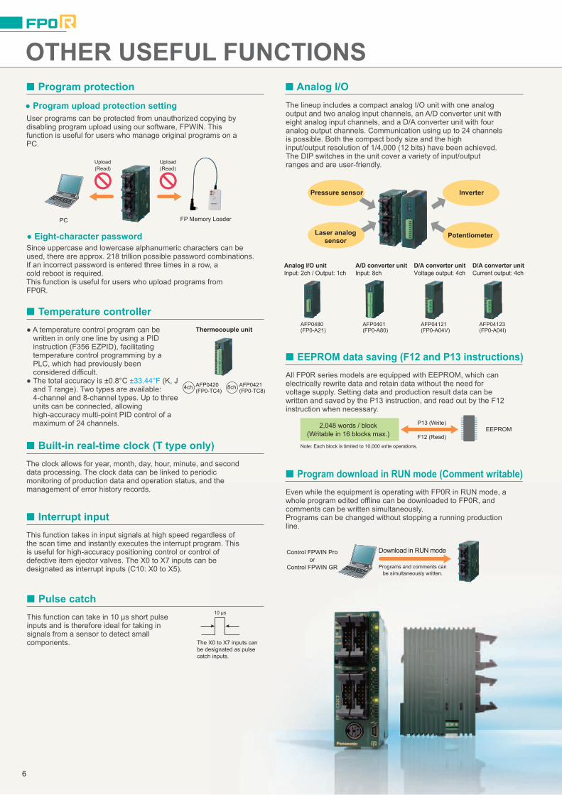
The lineup includes a compact analog I/O unit with one analogoutput and two analog input channels, an A/D converter unit witheight analog input channels, and a D/A converter unit with fouranalog output channels. Communication using up to 24 channelsis possible. Both the compact body size and the highinput/output resolution of 1/4,000 (12 bits) have been achieved.The DIP switches in the unit cover a variety of input/outputranges and are user-friendly.
User programs can be protected from unauthorized copying bydisabling program upload using our software, FPWIN. Thisfunction is useful for users who manage original programs on aPC.
All FP0R series models are equipped with EEPROM, which canelectrically rewrite data and retain data without the need forvoltage supply. Setting data and production result data can bewritten and saved by the P13 instruction, and read out by the F12instruction when necessary.
A temperature control program can be written in only one line by using a PID instruction (F356 EZPID), facilitating temperature control programming by a PLC, which had previously been considered difficult.
The total accuracy is ±0.8°C ±33.44°F (K, J and T range). Two types are available: 4-channel and 8-channel types. Up to three units can be connected, allowing high-accuracy multi-point PID control of a maximum of 24 channels.
This function can take in 10 μs short pulseinputs and is therefore ideal for taking insignals from a sensor to detect smallcomponents.
The clock allows for year, month, day, hour, minute, and seconddata processing. The clock data can be linked to periodicmonitoring of production data and operation status, and themanagement of error history records. Even while the equipment is operating with FP0R in RUN mode, a
whole program edited offline can be downloaded to FP0R, andcomments can be written simultaneously.Programs can be changed without stopping a running productionline.
This function takes in input signals at high speed regardless ofthe scan time and instantly executes the interrupt program. Thisis useful for high-accuracy positioning control or control ofdefective item ejector valves. The X0 to X7 inputs can be designated as interrupt inputs (C10: X0 to X5).
Eight-character password
FP Memory LoaderPC
Upload(Read)
Since uppercase and lowercase alphanumeric characters can beused, there are approx. 218 trillion possible password combinations.If an incorrect password is entered three times in a row, acold reboot is required.This function is useful for users who upload programs fromFP0R.
Program upload protection setting
2,048 words / block(Writable in 16 blocks max.)
P13 (Write)
Download in RUN mode
The X0 to X7 inputs canbe designated as pulsecatch inputs.
F12 (Read)EEPROM
Control FPWIN Proor
Control FPWIN GR
Note: Each block is limited to 10,000 write operations.
10 μs
Upload(Read)
Programs and comments canbe simultaneously written.
AFP0420(FP0-TC4)
AFP0421(FP0-TC8)
AFP0401(FP0-A80)
AFP0480(FP0-A21)
AFP04123(FP0-A04I)
AFP04121(FP0-A04V)
Analog I/O unitInput: 2ch / Output: 1ch
A/D converter unitInput: 8ch
D/A converter unitVoltage output: 4ch
D/A converter unitCurrent output: 4ch
Thermocouple unit
4ch 8ch
LD
ST
FBD
SFC
I L
LadderDiagram
StructuredText
FunctionBlockDiagram
SequentialFunctionChart
InstructionList
Analog I/O
EEPROM data saving (F12 and P13 instructions)
Temperature controller
Program protection
Pulse catch
Built-in real-time clock (T type only)
Program download in RUN mode (Comment writable)
Interrupt input
Note: Only Ver. 6.2 or later is compatible with Windows 7. (To be released in September 2011)
Note: Only Ver. 2.90 or later is compatible with Windows 7.
6 7

Pressure sensor
Laser analogsensor
Inverter
Potentiometer
Control FPWIN Pro (IEC61131-3 compliant Windows version software)
Control FPWIN GR (Windows version software)
Features
Programming in the language most suited to the process
Easy-to-understand, efficient programs can be created, for example, byusing a ladder program for machine control or ST for communicationscontrol.
Programming in the language you are good atProgramming time can be greatly reduced by the easy ability to split andthen integrate programming for each function and process.
1. Five programming languages can be used.Programming can be done using the language most familiar to the developer or using the language most suited to the process to be performed. High-level (structured text) languages that allow structuring, such as C, are supported.
2. Easy to reuse well-proven programsEfficiency when writing programs has been greatly increased by being able to split programming up for each function and process using structured programming.
3. Keep know-how from getting outBy "black boxing" a part of a program, you can prevent know-how from leaking out and improve the program's maintainability.
4. Uploading of source programs from PLC possible.Maintainability increased by being able to load programs and comments from the PLC.
5. Programming for all models in the FP series possible.
Main program(SFC)
Designer A(SFC)
Positioningprogram (ST) Completed
programCompletedprogram
Designer B(ST)
Communicationsprogram (ST)
Designer C(ST)
Malfunction handlingprogram (ladder)
Designer D(ladder)
Compliant with international standard IEC61131-3 Programming software approved by PLC Open
Operational Environment
OS
Hard disk capacity
CPU
Onboard memory
Screen resolution
Display colors
Applicable PLC
Windows 2000/XP/Vista/7 (Note)
At least 120 MB
Pentium III processor (700 MHz) or compatible
At least 256 MB RAM or more
At least 1,024 x 768
High Color (16-bit) or higher
FP0R/FP0/FPΣ/FP-X/FP-e/FP2/FP2SH
Features
Operational EnvironmentOS
Hard disk capacity
CPU
Onboard memory
Screen resolution
Display colors
Applicable PLC
Windows 98/Me/2000/XP/Vista/7 (Note)
At least 40 MB
Pentium 100 MHz or higher
At least 64 MB (depends on OS)
At least 1,024 x 768
High Color (16-bit) or higher
FP0R/FP0/FPΣ/FP-X/FP-e/FP2/FP2SH
1. Easy field operations not requiring the use of a mouse for data entry, search, writing, monitoring and timer changes, all carried out only from the keyboard.
2. All FP series PLCs are supported.3. Easy programming with wizard functions.4. Communication with GTWIN and PCWAY
simultaneously through the same port.5. A simulation function is available.
Program status display
Program display Search windowAllows you to searchvarious data
Tool barAccess often-usedfunctions using icons.
Datamonitoringwindow
Relaymonitoringwindow
Function barButtons for instruction inputand confirmation,on-line/off-line selection andPLC mode selection.
The ladder programming software for FP series Highly operational software tool for maximizing convenience in the field
* FP0R is compatible with Ver. 2.8 or later.
* FP0R is compatible with Ver. 6.1 or later.
OTHER USEFUL FUNCTIONS PROGRAMMING SOFTWARE
The lineup includes a compact analog I/O unit with one analogoutput and two analog input channels, an A/D converter unit witheight analog input channels, and a D/A converter unit with fouranalog output channels. Communication using up to 24 channelsis possible. Both the compact body size and the highinput/output resolution of 1/4,000 (12 bits) have been achieved.The DIP switches in the unit cover a variety of input/outputranges and are user-friendly.
User programs can be protected from unauthorized copying bydisabling program upload using our software, FPWIN. Thisfunction is useful for users who manage original programs on aPC.
All FP0R series models are equipped with EEPROM, which canelectrically rewrite data and retain data without the need forvoltage supply. Setting data and production result data can bewritten and saved by the P13 instruction, and read out by the F12instruction when necessary.
A temperature control program can be written in only one line by using a PID instruction (F356 EZPID), facilitating temperature control programming by a PLC, which had previously been considered difficult.
The total accuracy is ±0.8°C ±33.44°F (K, J and T range). Two types are available: 4-channel and 8-channel types. Up to three units can be connected, allowing high-accuracy multi-point PID control of a maximum of 24 channels.
This function can take in 10 μs short pulseinputs and is therefore ideal for taking insignals from a sensor to detect smallcomponents.
The clock allows for year, month, day, hour, minute, and seconddata processing. The clock data can be linked to periodicmonitoring of production data and operation status, and themanagement of error history records. Even while the equipment is operating with FP0R in RUN mode, a
whole program edited offline can be downloaded to FP0R, andcomments can be written simultaneously.Programs can be changed without stopping a running productionline.
This function takes in input signals at high speed regardless ofthe scan time and instantly executes the interrupt program. Thisis useful for high-accuracy positioning control or control ofdefective item ejector valves. The X0 to X7 inputs can be designated as interrupt inputs (C10: X0 to X5).
Eight-character password
FP Memory LoaderPC
Upload(Read)
Since uppercase and lowercase alphanumeric characters can beused, there are approx. 218 trillion possible password combinations.If an incorrect password is entered three times in a row, acold reboot is required.This function is useful for users who upload programs fromFP0R.
Program upload protection setting
2,048 words / block(Writable in 16 blocks max.)
P13 (Write)
Download in RUN mode
The X0 to X7 inputs canbe designated as pulsecatch inputs.
F12 (Read)EEPROM
Control FPWIN Proor
Control FPWIN GR
Note: Each block is limited to 10,000 write operations.
10 μs
Upload(Read)
Programs and comments canbe simultaneously written.
AFP0420(FP0-TC4)
AFP0421(FP0-TC8)
AFP0401(FP0-A80)
AFP0480(FP0-A21)
AFP04123(FP0-A04I)
AFP04121(FP0-A04V)
Analog I/O unitInput: 2ch / Output: 1ch
A/D converter unitInput: 8ch
D/A converter unitVoltage output: 4ch
D/A converter unitCurrent output: 4ch
Thermocouple unit
4ch 8ch
LD
ST
FBD
SFC
I L
LadderDiagram
StructuredText
FunctionBlockDiagram
SequentialFunctionChart
InstructionList
Analog I/O
EEPROM data saving (F12 and P13 instructions)
Temperature controller
Program protection
Pulse catch
Built-in real-time clock (T type only)
Program download in RUN mode (Comment writable)
Interrupt input
Note: Only Ver. 6.2 or later is compatible with Windows 7. (To be released in September 2011)
Note: Only Ver. 2.90 or later is compatible with Windows 7.
6 7
INSTALLATION AND OPTIONS
The control unit width is only 25 mm 0.98 in*.Even when expanded to allow for 128 I/O points,the total width is only 105 mm 4.13 in.
Up to three expansion units can be directlyconnected without connection cables.
* The 32 I/O points type control unit is 30 mm 1.18 in in width.
Three options for installation methods
DIN rail Slim type mounting plate Flat type mounting plate** Cannot be used when expanded.
Controlunit
Expansionunit
Expansionunit
Expansionunit
The expansion units can be directly connected to the control unitwith a simple operation using the expansion connector and locklever on the side of the unit. Dedicated cables or backplanes arenot necessary for expansion.
( )Up to 3 unitscan be expanded.
A terminal block type and a connector type are available. Both can be detached for easy wiring.
The control unit can be directly mounted on a panel by using the optional flattype mounting plate.
Part number: AFP0806
Part number: AFP0802 (2 sokets per pack) Part number: AFP0801 (2 sokets per pack)
Terminal socketAttaches to relay output and terminal block types.
Molex socketAttaches to relay output and molex connector types.
Wire-press socketAttaches to transistor output type.
FP0R Power cable (Length: 1 m 3.28 ft)Attaches to FP0R control unit.
Part number: AFP0807 (2 sokets per pack) Part number: AFPG805 (1 cable per pack)
Notes: 1)2)3)
Relay output molex type I/O cableLoose-wiring cable (9 leads) with molex socket attached at one end, AWG20, 0.5 mm2, 1 set: 2 cables (blue & white)
Part number: AFP0805 Part number: AXY52000FP
< Length: 3 m 9.84 ft > 2 cable set
Part number: AFP0553< Length: 1 m 3.28 ft > 2 cable set
Part number: AFP0551
Transistor output type I/O cableLoose-wiring cable (10 leads) with connectors attached at one end, AWG22, 0.3 mm2, 1 set: 2 cables (blue & white).
< Length: 3 m 9.84 ft > 2 cable set
Part number: AFP0523
Part number: AFP0808 (including 4 pieces)
< Length: 1 m 3.28 ft > 2 cable set
Part number: AFP0521
Wiring tools
Parts for mounting
I/O cables
Maintenance parts
Flat cable connector set (10 leads)
Flat type mounting plateScrew-stop attachment plate, Flat model
Part number: AFP0804 (including 10 pieces)
FP0 Slim type mounting plateScrew-stop attachment plate, Slim model
Part number: AFP0803 (including 10 pieces)
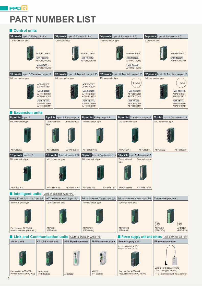
PART NUMBER LIST Control units
Expansion units
Intelligent units
AFP0RE8X AFP0RE8RS AFP0RE8YRS AFP0RE8YT AFP0RE8YP
AFP0RE16X AFP0RE16YT AFP0RE16T AFP0RE16RS AFP0RE16RM
AFP0RE32T AFP0RE32PAFP0RE8RM
AFP0RE16YP AFP0RE16P
Part number: AFP0480Product number: (FP0-A21)
AFP0420(FP0-TC4)
AFP0421(FP0-TC8)
AFP0401(FP0-A80)
AFP04123(FP0-A04I)
AFP04121(FP0-A04V)
MIL connector type
MIL connector type
MIL connector typeMIL connector type MIL connector type
MIL connector type MIL connector type
Terminal block type
Terminal block type
Terminal block type Terminal block type Terminal block type Terminal block type
Terminal block type
Terminal block type
Connector type
Connector type
Terminal block type
Connector type
Connector type
MIL connector type MIL connector type
T type F type
MIL connector type
10 points Input: 6, Relay output: 4
16 points Input: 8, Transistor output: 8
8 points Input: 4, Relay output: 4
Analog I/O unit Input: 2 ch, Output: 1 ch A/D converter unit Input: 8 ch D/A converter unit Voltage output: 4 ch D/A converter unit Current output: 4 ch Thermocouple unit
8 points Input: 8 8 points Relay output: 8 8 points Transistor output: 8
16 points Input: 8, Relay output: 816 points Input: 8, Transistor output: 816 points Input: 16 16 points Transistor output: 16
32 points Input: 16, Transistor output: 16
32 points Input: 16, Transistor output: 16 32 points Input: 16, Transistor output: 16 32 points Input: 16, Transistor output: 16
10 points Input: 6, Relay output: 4 14 points Input: 8, Relay output: 6 14 points Input: 8, Relay output: 6
AFP0RT32MPAFP0RT32MTwith RS485
AFP0RT32CPAFP0RT32CTwith RS232C
AFP0RF32MTAFP0RF32MP
with RS485
AFP0RF32CTAFP0RF32CP
with RS232C
AFP0RC10RS
AFP0RC10CRSwith RS232C
AFP0RC10MRSwith RS485
AFP0RC10RM
AFP0RC10CRMwith RS232C
AFP0RC14RS
AFP0RC14CRSwith RS232C
AFP0RC14MRSwith RS485
AFP0RC14RM
AFP0RC14CRMwith RS232C
4 ch 8 ch
Units in common with FP0
Installation
Options
Terminal screwdriverNecessary when wiring relay output type andterminals block (Phoenix).
Molex connector pressure contact toolNecessary when wiring relay output type and molex connectors.
Multi-wire connector pressure contact toolNecessary when wiring transistor output type connectors.
The control unit is pocket-sized: W 25 x H 90 x D 60 mm W 0.98 xH 3.54 x D 2.36 in.The number of I/O points can be expanded up to 128. Even withthe maximum expansion, the size is only W 105 x H 90 x D 60 mmW 4.13 x H 3.54 x D 2.36 in. The ultra-compact body size andinstallation area facilitate the miniaturization of target machines,equipment, and control panels.
One I/O cable set (2 cables) is necessary with the following models: C10RS / C10RM, C14RS / C14RM, E8RS / E8RM, E16RS / E16RMOne I/O cable set (2 cables) is necessary with the following models: C16T / E16X, E16T / E16YTTwo I/O cable sets (total 4 cables) are necessary with the following models: C32T / E32T
AFP0RC32TAFP0RC32P
AFP0RC32CPAFP0RC32CTwith RS232C
AFP0RC32MPAFP0RC32MT
with RS485
with RS232C
AFP0RC16P
AFP0RC16CP
AFP0RC16T
AFP0RC16CT
with RS485
AFP0RC16MPAFP0RC16MT
Link and Communication units Power supply unit and others
Part number: AFP0732Product number: (FP0-IOL)
Part number: AFP0634Product number: (FP0-PSA4)AKS1202
AFP0611(FP-WEB2)
Data clear type: AFP8670Data hold type: AFP8671* FP0R is compatible with Ver. 2.0 or later.
Input: 100 to 240 V AC, Output: 24 V DC, 0.7 A
I/O link unit CC-Link slave unit KS1 Signal converter FP Web-server 2 Unit Power supply unit FP memory loader
AFP07943(FP0-CCLS)
Units in common with FP0 Units in common with FP0
8 9

INSTALLATION AND OPTIONS
The control unit width is only 25 mm 0.98 in*.Even when expanded to allow for 128 I/O points,the total width is only 105 mm 4.13 in.
Up to three expansion units can be directlyconnected without connection cables.
* The 32 I/O points type control unit is 30 mm 1.18 in in width.
Three options for installation methods
DIN rail Slim type mounting plate Flat type mounting plate** Cannot be used when expanded.
Controlunit
Expansionunit
Expansionunit
Expansionunit
The expansion units can be directly connected to the control unitwith a simple operation using the expansion connector and locklever on the side of the unit. Dedicated cables or backplanes arenot necessary for expansion.
( )Up to 3 unitscan be expanded.
A terminal block type and a connector type are available. Both can be detached for easy wiring.
The control unit can be directly mounted on a panel by using the optional flattype mounting plate.
Part number: AFP0806
Part number: AFP0802 (2 sokets per pack) Part number: AFP0801 (2 sokets per pack)
Terminal socketAttaches to relay output and terminal block types.
Molex socketAttaches to relay output and molex connector types.
Wire-press socketAttaches to transistor output type.
FP0R Power cable (Length: 1 m 3.28 ft)Attaches to FP0R control unit.
Part number: AFP0807 (2 sokets per pack) Part number: AFPG805 (1 cable per pack)
Notes: 1)2)3)
Relay output molex type I/O cableLoose-wiring cable (9 leads) with molex socket attached at one end, AWG20, 0.5 mm2, 1 set: 2 cables (blue & white)
Part number: AFP0805 Part number: AXY52000FP
< Length: 3 m 9.84 ft > 2 cable set
Part number: AFP0553< Length: 1 m 3.28 ft > 2 cable set
Part number: AFP0551
Transistor output type I/O cableLoose-wiring cable (10 leads) with connectors attached at one end, AWG22, 0.3 mm2, 1 set: 2 cables (blue & white).
< Length: 3 m 9.84 ft > 2 cable set
Part number: AFP0523
Part number: AFP0808 (including 4 pieces)
< Length: 1 m 3.28 ft > 2 cable set
Part number: AFP0521
Wiring tools
Parts for mounting
I/O cables
Maintenance parts
Flat cable connector set (10 leads)
Flat type mounting plateScrew-stop attachment plate, Flat model
Part number: AFP0804 (including 10 pieces)
FP0 Slim type mounting plateScrew-stop attachment plate, Slim model
Part number: AFP0803 (including 10 pieces)
PART NUMBER LIST Control units
Expansion units
Intelligent units
AFP0RE8X AFP0RE8RS AFP0RE8YRS AFP0RE8YT AFP0RE8YP
AFP0RE16X AFP0RE16YT AFP0RE16T AFP0RE16RS AFP0RE16RM
AFP0RE32T AFP0RE32PAFP0RE8RM
AFP0RE16YP AFP0RE16P
Part number: AFP0480Product number: (FP0-A21)
AFP0420(FP0-TC4)
AFP0421(FP0-TC8)
AFP0401(FP0-A80)
AFP04123(FP0-A04I)
AFP04121(FP0-A04V)
MIL connector type
MIL connector type
MIL connector typeMIL connector type MIL connector type
MIL connector type MIL connector type
Terminal block type
Terminal block type
Terminal block type Terminal block type Terminal block type Terminal block type
Terminal block type
Terminal block type
Connector type
Connector type
Terminal block type
Connector type
Connector type
MIL connector type MIL connector type
T type F type
MIL connector type
10 points Input: 6, Relay output: 4
16 points Input: 8, Transistor output: 8
8 points Input: 4, Relay output: 4
Analog I/O unit Input: 2 ch, Output: 1 ch A/D converter unit Input: 8 ch D/A converter unit Voltage output: 4 ch D/A converter unit Current output: 4 ch Thermocouple unit
8 points Input: 8 8 points Relay output: 8 8 points Transistor output: 8
16 points Input: 8, Relay output: 816 points Input: 8, Transistor output: 816 points Input: 16 16 points Transistor output: 16
32 points Input: 16, Transistor output: 16
32 points Input: 16, Transistor output: 16 32 points Input: 16, Transistor output: 16 32 points Input: 16, Transistor output: 16
10 points Input: 6, Relay output: 4 14 points Input: 8, Relay output: 6 14 points Input: 8, Relay output: 6
AFP0RT32MPAFP0RT32MTwith RS485
AFP0RT32CPAFP0RT32CTwith RS232C
AFP0RF32MTAFP0RF32MP
with RS485
AFP0RF32CTAFP0RF32CP
with RS232C
AFP0RC10RS
AFP0RC10CRSwith RS232C
AFP0RC10MRSwith RS485
AFP0RC10RM
AFP0RC10CRMwith RS232C
AFP0RC14RS
AFP0RC14CRSwith RS232C
AFP0RC14MRSwith RS485
AFP0RC14RM
AFP0RC14CRMwith RS232C
4 ch 8 ch
Units in common with FP0
Installation
Options
Terminal screwdriverNecessary when wiring relay output type andterminals block (Phoenix).
Molex connector pressure contact toolNecessary when wiring relay output type and molex connectors.
Multi-wire connector pressure contact toolNecessary when wiring transistor output type connectors.
The control unit is pocket-sized: W 25 x H 90 x D 60 mm W 0.98 xH 3.54 x D 2.36 in.The number of I/O points can be expanded up to 128. Even withthe maximum expansion, the size is only W 105 x H 90 x D 60 mmW 4.13 x H 3.54 x D 2.36 in. The ultra-compact body size andinstallation area facilitate the miniaturization of target machines,equipment, and control panels.
One I/O cable set (2 cables) is necessary with the following models: C10RS / C10RM, C14RS / C14RM, E8RS / E8RM, E16RS / E16RMOne I/O cable set (2 cables) is necessary with the following models: C16T / E16X, E16T / E16YTTwo I/O cable sets (total 4 cables) are necessary with the following models: C32T / E32T
AFP0RC32TAFP0RC32P
AFP0RC32CPAFP0RC32CTwith RS232C
AFP0RC32MPAFP0RC32MT
with RS485
with RS232C
AFP0RC16P
AFP0RC16CP
AFP0RC16T
AFP0RC16CT
with RS485
AFP0RC16MPAFP0RC16MT
Link and Communication units Power supply unit and others
Part number: AFP0732Product number: (FP0-IOL)
Part number: AFP0634Product number: (FP0-PSA4)AKS1202
AFP0611(FP-WEB2)
Data clear type: AFP8670Data hold type: AFP8671* FP0R is compatible with Ver. 2.0 or later.
Input: 100 to 240 V AC, Output: 24 V DC, 0.7 A
I/O link unit CC-Link slave unit KS1 Signal converter FP Web-server 2 Unit Power supply unit FP memory loader
AFP07943(FP0-CCLS)
Units in common with FP0 Units in common with FP0
8 9

OPTIONS
RT-3 unit relays (Power PhotoMOS relay type)RT-3 unit relay
OPTIONS
Notes:
Contactarrangement Type Rated input
voltageRT-3 Unit relay
Product No. Part No. Packing quantity
1 Form A × 4
DC only (equipped with AQZ102)AC / DC dual use (equipped with AQZ204)
12 V DC RT3SP1-12V AY3400124 V DC RT3SP1-24V AY3400212 V DC RT3SP2-12V AY3500124 V DC
RT-3 unit relays (PA relay type)
RT3SP2-24V AY35002
Inner carton: 1 pieceOuter case: 20 pieces
Inner carton: 1 pieceOuter case: 20 pieces
RT-3 unit relay
Notes:
1) Only for use with Power PhotoMOS relays. Cannot be equipped with PA relays.2) Please consult us other contact arrangement.
1) Only for use with PA relay type. Cannot be equipped with Power PhotoMOS relay stndard type. However, equipping with voltage sensitive type is possible.2) 5 V DC type relays are also available. Please consult us.3) Please consult us other contact arrangement.
Note: Never mount relays into this product other than those given above. Doing so will cause malfunction, breakdown, and breakdown of the connected product.
Contactarrangement Rated input voltage
RT-3 Unit relayProduct No. Part No. Packing quantity
1 Form A × 412 V DC RT3S-12V AY3300124 V DC RT3S-24V AY33002
4-point terminals4-point terminals
Packing quantity: inner carton: 1 piece, outer case: 20 pieces
Type Rated input voltagePA relay and Voltage sensitive type power PhotoMOS relay type 12, 24 V DC
Part No.AY30000
Mountable relays for 4-point terminalProduct name
PA relay
Power PhotoMOS relay (voltage sensitive type)
PA relay Power PhotoMOS relay (voltage sensitive type)
Part No.APA3311 and APA3312AQZ10*D (DC only) AQZ20*D (AC / DC dual use)
RT-2 relay terminalsDIN rail mounting type1. Pressure connector connect type
Part No.AY231501
I / O type
Input device
Product No.RT2S-ID16-12V
AY231502RT2S-ID16-24V
AY232502RT2S-OD16-24VAY232501
Rated voltage12 V DC24 V DC
24 V DC12 V DC
Output deviceRT2S-OD16-12V
Packing quantity
Inner carton: 1 pieceOuter case: 10 pieces
2. Wire-direct connect typePart No.
AY231511I / O type
Input device
Product No.RT2S-C-ID16-12V
AY231512RT2S-C-ID16-24V
AY232512RT2S-C-OD16-24VAY232511
Rated voltage12 V DC24 V DC
24 V DC12 V DC
Output deviceRT2S-C-OD16-12V
Packing quantity
Inner carton: 1 pieceOuter case: 10 pieces
Product name Product numberPM-PW8-739/3.5PM-FP0X-M733SS-F1M
PM-M733-3X8PC-S1PM-FP0Y-M733SS-F1M
Ident number5119783251251907
5123807651251909
(1) Common terminal block(2) PM flexible cable for input
(4) 8 ponts, MIL-DIO station(3) PM flexible cable for output
Pressure connector connect type
Expansion cable with wire-pressed terminal
Expansion cable
M type 16-point, 34-pin output cable
Wire-direct connect type
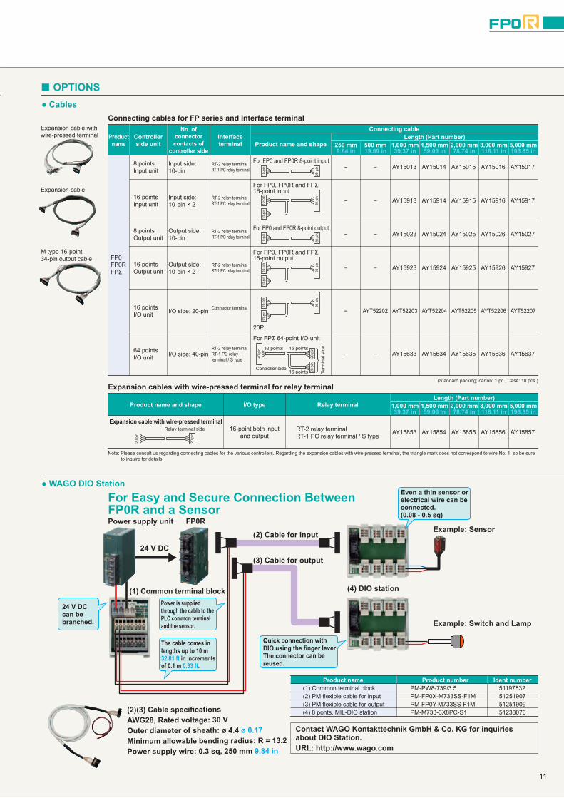
Cables
WAGO DIO Station
Connecting cables for FP series and Interface terminal
OPTIONS
For Easy and Secure Connection Between FP0R and a Sensor
(Standard packing; carton: 1 pc., Case: 10 pcs.)
Note: Please consult us regarding connecting cables for the various controllers. Regarding the expansion cables with wire-pressed terminal, the triangle mark does not correspond to wire No. 1, so be sure to inquire for details.
Productname
Controllerside unit
No. ofconnectorcontacts of
controller side
Interfaceterminal
Connecting cable
Product name and shapeLength (Part number)
250 mm 500 mm 1,000 mm 1,500 mm 2,000 mm 3,000 mm 5,000 mm
FP0FP0RFPΣ
For FP0 and FP0R 8-point input8 points Input unit
Input side: 10-pin
For FP0, FP0R and FPΣ 16-point input
Input side: 10-pin × 2
For FP0 and FP0R 8-point outputOutput side: 10-pin
For FP0, FP0R and FPΣ 16-point output
Output side: 10-pin × 2
20P
Controller side
Relay terminal side
32 points 16 points
16 points Term
inal
sid
e
I/O side: 20-pin
For FPΣ 64-point I/O unit
I/O side: 40-pin
RT-2 relay terminalRT-1 PC relay terminal AY15013 AY15014 AY15015 AY15016 AY15017−−
16 points Input unit
RT-2 relay terminalRT-1 PC relay terminal AY15913 AY15914 AY15915 AY15916 AY15917−−
8 points Output unit
RT-2 relay terminalRT-1 PC relay terminal AY15023 AY15024 AY15025 AY15026 AY15027−−
16 points Output unit
RT-2 relay terminalRT-1 PC relay terminal AY15923 AY15924 AY15925 AY15926 AY15927−−
16 points I/O unit
Connector terminal AYT52203AYT52202 AYT52204 AYT52205 AYT52206 AYT52207−
64 points I/O unit
RT-2 relay terminalRT-1 PC relay terminal / S type
AY15633 AY15634 AY15635 AY15636 AY15637−−
Expansion cables with wire-pressed terminal for relay terminal
Power is supplied through the cable to the PLC common terminal and the sensor.
24 V DC can be branched.
(2)(3) Cable specificationsAWG28, Rated voltage: 30 VOuter diameter of sheath: ø 4.4 ø 0.17Minimum allowable bending radius: R = 13.2Power supply wire: 0.3 sq, 250 mm 9.84 in
Quick connection with DIO using the finger leverThe connector can be reused.
The cable comes in lengths up to 10 m 32.81 ft in increments of 0.1 m 0.33 ft.
Power supply unit FP0R
(2) Cable for inputExample: Sensor
(4) DIO station
Example: Switch and Lamp
(3) Cable for output24 V DC
(1) Common terminal block
Even a thin sensor or electrical wire can be connected. (0.08 - 0.5 sq)
Contact WAGO Kontakttechnik GmbH & Co. KG for inquiries about DIO Station.URL: http://www.wago.com
Relay terminalI/O typeLength (Part number)
1,000 mm 1,500 mm 2,000 mm 3,000 mm 5,000 mm
9.84 in 19.69 in 39.37 in 59.06 in 78.74 in 118.11 in 196.85 in
39.37 in 59.06 in 78.74 in 118.11 in 196.85 in
RT-2 relay terminalRT-1 PC relay terminal / S type
16-point both inputand output
Product name and shape
Expansion cable with wire-pressed terminal
AY15853 AY15854 AY15855 AY15856 AY15857
10-p
in10
-pin
10-p
in10
-pin
10-p
in10
-pin
10-p
in10
-pin
20-p
in20
-pin
20-p
in20
-pin
20-p
in20
-pin
20-p
in
40-p
in
20-p
in
20-p
in
Mountable relays
10 11
OPTIONS
RT-3 unit relays (Power PhotoMOS relay type)RT-3 unit relay
OPTIONS
Notes:
Contactarrangement Type Rated input
voltageRT-3 Unit relay
Product No. Part No. Packing quantity
1 Form A × 4
DC only (equipped with AQZ102)AC / DC dual use (equipped with AQZ204)
12 V DC RT3SP1-12V AY3400124 V DC RT3SP1-24V AY3400212 V DC RT3SP2-12V AY3500124 V DC
RT-3 unit relays (PA relay type)
RT3SP2-24V AY35002
Inner carton: 1 pieceOuter case: 20 pieces
Inner carton: 1 pieceOuter case: 20 pieces
RT-3 unit relay
Notes:
1) Only for use with Power PhotoMOS relays. Cannot be equipped with PA relays.2) Please consult us other contact arrangement.
1) Only for use with PA relay type. Cannot be equipped with Power PhotoMOS relay stndard type. However, equipping with voltage sensitive type is possible.2) 5 V DC type relays are also available. Please consult us.3) Please consult us other contact arrangement.
Note: Never mount relays into this product other than those given above. Doing so will cause malfunction, breakdown, and breakdown of the connected product.
Contactarrangement Rated input voltage
RT-3 Unit relayProduct No. Part No. Packing quantity
1 Form A × 412 V DC RT3S-12V AY3300124 V DC RT3S-24V AY33002
4-point terminals4-point terminals
Packing quantity: inner carton: 1 piece, outer case: 20 pieces
Type Rated input voltagePA relay and Voltage sensitive type power PhotoMOS relay type 12, 24 V DC
Part No.AY30000
Mountable relays for 4-point terminalProduct name
PA relay
Power PhotoMOS relay (voltage sensitive type)
PA relay Power PhotoMOS relay (voltage sensitive type)
Part No.APA3311 and APA3312AQZ10*D (DC only) AQZ20*D (AC / DC dual use)
RT-2 relay terminalsDIN rail mounting type1. Pressure connector connect type
Part No.AY231501
I / O type
Input device
Product No.RT2S-ID16-12V
AY231502RT2S-ID16-24V
AY232502RT2S-OD16-24VAY232501
Rated voltage12 V DC24 V DC
24 V DC12 V DC
Output deviceRT2S-OD16-12V
Packing quantity
Inner carton: 1 pieceOuter case: 10 pieces
2. Wire-direct connect typePart No.
AY231511I / O type
Input device
Product No.RT2S-C-ID16-12V
AY231512RT2S-C-ID16-24V
AY232512RT2S-C-OD16-24VAY232511
Rated voltage12 V DC24 V DC
24 V DC12 V DC
Output deviceRT2S-C-OD16-12V
Packing quantity
Inner carton: 1 pieceOuter case: 10 pieces
Product name Product numberPM-PW8-739/3.5PM-FP0X-M733SS-F1M
PM-M733-3X8PC-S1PM-FP0Y-M733SS-F1M
Ident number5119783251251907
5123807651251909
(1) Common terminal block(2) PM flexible cable for input
(4) 8 ponts, MIL-DIO station(3) PM flexible cable for output
Pressure connector connect type
Expansion cable with wire-pressed terminal
Expansion cable
M type 16-point, 34-pin output cable
Wire-direct connect type
Cables
WAGO DIO Station
Connecting cables for FP series and Interface terminal
OPTIONS
For Easy and Secure Connection Between FP0R and a Sensor
(Standard packing; carton: 1 pc., Case: 10 pcs.)
Note: Please consult us regarding connecting cables for the various controllers. Regarding the expansion cables with wire-pressed terminal, the triangle mark does not correspond to wire No. 1, so be sure to inquire for details.
Productname
Controllerside unit
No. ofconnectorcontacts of
controller side
Interfaceterminal
Connecting cable
Product name and shapeLength (Part number)
250 mm 500 mm 1,000 mm 1,500 mm 2,000 mm 3,000 mm 5,000 mm
FP0FP0RFPΣ
For FP0 and FP0R 8-point input8 points Input unit
Input side: 10-pin
For FP0, FP0R and FPΣ 16-point input
Input side: 10-pin × 2
For FP0 and FP0R 8-point outputOutput side: 10-pin
For FP0, FP0R and FPΣ 16-point output
Output side: 10-pin × 2
20P
Controller side
Relay terminal side
32 points 16 points
16 points Term
inal
sid
e
I/O side: 20-pin
For FPΣ 64-point I/O unit
I/O side: 40-pin
RT-2 relay terminalRT-1 PC relay terminal AY15013 AY15014 AY15015 AY15016 AY15017−−
16 points Input unit
RT-2 relay terminalRT-1 PC relay terminal AY15913 AY15914 AY15915 AY15916 AY15917−−
8 points Output unit
RT-2 relay terminalRT-1 PC relay terminal AY15023 AY15024 AY15025 AY15026 AY15027−−
16 points Output unit
RT-2 relay terminalRT-1 PC relay terminal AY15923 AY15924 AY15925 AY15926 AY15927−−
16 points I/O unit
Connector terminal AYT52203AYT52202 AYT52204 AYT52205 AYT52206 AYT52207−
64 points I/O unit
RT-2 relay terminalRT-1 PC relay terminal / S type
AY15633 AY15634 AY15635 AY15636 AY15637−−
Expansion cables with wire-pressed terminal for relay terminal
Power is supplied through the cable to the PLC common terminal and the sensor.
24 V DC can be branched.
(2)(3) Cable specificationsAWG28, Rated voltage: 30 VOuter diameter of sheath: ø 4.4 ø 0.17Minimum allowable bending radius: R = 13.2Power supply wire: 0.3 sq, 250 mm 9.84 in
Quick connection with DIO using the finger leverThe connector can be reused.
The cable comes in lengths up to 10 m 32.81 ft in increments of 0.1 m 0.33 ft.
Power supply unit FP0R
(2) Cable for inputExample: Sensor
(4) DIO station
Example: Switch and Lamp
(3) Cable for output24 V DC
(1) Common terminal block
Even a thin sensor or electrical wire can be connected. (0.08 - 0.5 sq)
Contact WAGO Kontakttechnik GmbH & Co. KG for inquiries about DIO Station.URL: http://www.wago.com
Relay terminalI/O typeLength (Part number)
1,000 mm 1,500 mm 2,000 mm 3,000 mm 5,000 mm
9.84 in 19.69 in 39.37 in 59.06 in 78.74 in 118.11 in 196.85 in
39.37 in 59.06 in 78.74 in 118.11 in 196.85 in
RT-2 relay terminalRT-1 PC relay terminal / S type
16-point both inputand output
Product name and shape
Expansion cable with wire-pressed terminal
AY15853 AY15854 AY15855 AY15856 AY15857
10-p
in10
-pin
10-p
in10
-pin
10-p
in10
-pin
10-p
in10
-pin
20-p
in20
-pin
20-p
in20
-pin
20-p
in20
-pin
20-p
in
40-p
in
20-p
in
20-p
in
Mountable relays
10 11

Control unit replacement table
FP0 FP0R
Product name Product nameProduct No. Part No. Part No.
FP0-C10RSFP0-C10RMFP0-C10CRSFP0-C10CRMFP0-C14RSFP0-C14RMFP0-C14CRSFP0-C14CRMFP0-C16TFP0-C16PFP0-C16CTFP0-C16CPFP0-C32TFP0-C32PFP0-C32CTFP0-C32CPFP0-T32CTFP0-T32CP
AFP0RC10RSAFP0RC10RMAFP0RC10CRSAFP0RC10CRMAFP0RC14RSAFP0RC14RMAFP0RC14CRSAFP0RC14CRMAFP0RC16TAFP0RC16PAFP0RC16CTAFP0RC16CPAFP0RC32TAFP0RC32PAFP0RC32CTAFP0RC32CPAFP0RT32CTAFP0RT32CP
AFP0RF32CTAFP0RF32CP
FP0-SL1
AFP02123AFP02113AFP02123CAFP02113CAFP02223AFP02213AFP02223CAFP02213CAFP02343AFP02353AFP02343CAFP02353CAFP02543AFP02553AFP02543CAFP02553CAFP02643CAFP02653C
AFP02700
Orderreceiving
will bediscontinued
in August2012.
Continue to be available
No corresponding models
FP0-C10 Control unit
FP0-C10 Control unit with RS232C port
FP0-C14 Control unit
FP0-C14 Control unit with RS232C port
FP0-C16 Control unit
FP0-C16 Control unit with RS232C port
FP0-C32 Control unit
FP0-C32 Control unit with RS232C port
FP0R-C10 Control unit
FP0R-C10 Control unit with RS232C port
FP0R-F32 Control unit with RS232C port
FP0R-C14 Control unit
FP0R-C14 Control unit with RS232C port
FP0R-C16 Control unit
FP0R-C16 Control unit with RS232C port
FP0R-C32 Control unit
FP0R-C32 Control unit with RS232C port
FP0-S-LINK Control unit with RS232C port
FP0-T32 Control unit with RS232C port, clock / calendar function and 10 k type
FP0R-T32 Control unit with RS232C port and real clock / calendar function
Expansion unit replacement table
FP0 FP0R
Product name Product nameProduct No. Part No. Part No.
FP0-E8XFP0-E8RSFP0-E8RMFP0-E8YRSFP0-E8YTFP0-E8YPFP0-E16XFP0-E16RSFP0-E16RMFP0-E16TFP0-E16PFP0-E16YTFP0-E16YPFP0-E32TFP0-E32P
AFP0RE8XAFP0RE8RSAFP0RE8RMAFP0RE8YRSAFP0RE8YTAFP0RE8YPAFP0RE16XAFP0RE16RSAFP0RE16RMAFP0RE16TAFP0RE16PAFP0RE16YTAFP0RE16YPAFP0RE32TAFP0RE32P
AFP03003AFP03023AFP03013AFP03020AFP03040AFP03050AFP03303AFP03323AFP03313AFP03343AFP03353AFP03340AFP03350AFP03543AFP03553
Orderreceiving
will bediscontinued
in August2012.
FP0-E8
FP0-E16
FP0-E32
FP0R-E8
FP0R-E16
FP0R-E32
Compatibility between FP0 and FP0R
COMPATIBILITY
Note: The F type has no compatible functions because it does not correspond to any units of the conventional FP0 series.
It is recommended that Control FPWIN Pro or FPWIN GR should be used for transporting FP0 programs to FP0R. Before an FP0 program is downloaded to FP0R, a message stating "Switch to FP0-compatible mode for the download?"
appears. If "Yes" is chosen, FP0R will automatically be set in FP0-compatible mode.
When the FP Memory Loader (AFP8670/AFP8671) is used to read a program from FP0 and transport it to FP0R, FP0R will automatically be set into FP0-compatible mode. For the program transport to FP0R, use FP Memory Loader Ver. 2.0 or later. (Ver. 1.1 and earlier versions are not compatible with FP0R.)
PC
Download an FP0program into FP0R.
Switched toFP0-compatiblemode.
The program isdownloaded.
FP Memory Loader
Switch toFP0-compatible
mode?Yes
FP0R has an "FP0-compatible mode". This mode provides conditions for functions, memory areas, system registers, etc. identical to those of FP0. If programs in FP0 are transported to FP0R, FP0R can function identically as FP0 did (with some exceptions described below).
The shape, outside dimensions, installation method, and the connector pin arrangement are identical to those of FP0.
This high degree of compatibility ensures easy and worry-free replacement of FP0 with FP0R even if the device or machine to be manufactured is identical.
Programs
Installation
FP0
FP0 specification items not covered by FP0-compatible mode (See "FP0R User's Manual" for details.)
Instruction P13: EEPROM write time
Instruction F170: PWM output frequency range
High-speed counter/pulse output elapsed value
Instruction F168: Home return
Instruction F169: Pulse output
Instruction F144: Serial data communications
5 ms / block (256 blocks max.: 1,280 ms)
0.15 Hz to 1 kHz
± 24 bits
The elapsed value is not counted during home return.
"Non-counting mode" selectable
Transmittable data size: Unlimited
100 ms in units of 32 blocks (256 blocks max.: 800 ms)* Writing even only one block takes 100 ms.
6 Hz to 1 kHz
± 32 bits
The elapsed value is counted during home return.
Counted and added even when "non-counting mode" is selected
Transmittable data size: 2,048
Item FP0R (FP0-compatible mode)
12 13

SPECIFICATIONS SPECIFICATIONS
C10, C14, C16C32, T32, F32
Performance specifications (FP0R Control units)
General specifications (FP0R Control units)
Input specifications (Common to control units and expansion units) (As for the limitation on the number of simultaneous ON points, please refer to the manual.)
Product type of FP0R control unit F32(Transistor output type only)
C32(Transistor output type only)
T32(Transistor output type only)
C16(Transistor output type only)
C14(Relay output type only)
C10(Relay output type only)
Programming method / Control method Relay symbol / Cyclic operation10 points
[Input: 6, Relay output: 4]
Max. 58 points
Max. 106 points
14 points[Input: 8, Relay output: 6]
Max. 62 points
Max. 110 points
16 points[Input: 8, Transistor output: 8]
Max. 112 points
Max. 112 points
32 points[Input: 16, Transistor output: 16]
Max. 128 points
Max. 128 points
32 points[Input: 16, Transistor output: 16]
Max. 128 points
Max. 128 points
Not availableNot available
4 points (50 kHz max. each) Two channels can be controlled individually.*4 points (6 Hz to 4.8 kHz)
Number of I/O points
No expansion(Control unit only)
With expansion 1* Same type of control and expansion units
With expansion 2* Mix type of relay and transistor units
Program memoryProgram capacity
Number of instructions
Operation speed
BasicHigh-levelUp to 3,000 steps3,001st and later steps
EEPROM (no backup battery required)
110 approx.210 approx.
Basic instructions: 0.08 µs Min. Timer instructions: 2.2 µs Min. High-level instructions: 0.32 µs (MV instruction) Min.Basic instructions: 0.58 µs Min. Timer instructions: 3.66 µs Min. High-level instructions: 1.62 µs (MV instruction) Min.
4,096 points1,024 points
14 words (IO to ID)256 words256 labels
Equivalent to the program capacity1,000 stages
500 subroutinesSingle-phase: 6 points (50 kHz max. each) 2-phase: 3 channels (15 kHz max. each)*
Total 8 points (with high speed counter)Input: 8 programs (6 programs for C10 only) / Periodic: 1 program / Pulse match: 4 programs
In units of 0.5 ms: 0.5 ms to 1.5 sec. / In units of 10 ms: 10 ms to 30 sec.In units of 0.5 ms: 0.5 ms to 600 ms
16 k steps 32 k steps
12,315 words 32,765 words
One RS485 port is mounted on each of C10MRS, C14MRS, C16MT, C16MP, C32MT, C32MP, T32MT, T32MP, F32MT and F32MP type(3P terminal block)Transmission speed (Baud rate): 115.2 kbps (It is possible to change to 19.2 kbps by the setting.), Transmission distance: 1,200 m 3,937 ft, Communication method: half duplex
One RS232C port is mounted on each of C10CRS, C10CRM, C14CRS, C14CRM, C16CT, C16CP, C32CT, C32CP, T32CT, T32CP, F32CT and F32CP type (3P terminal block) Transmission speed (Baud rate): 2,400 to 115,200 bits/s, Transmission distance: 15 m 9.8 ft. Communication method: half duplex
Stored program and system register in EEPROM
Stored fixed area in EEPROMCounter: 16 pointsInternal relay: 128 pointsData register: 315 words
Backup of the entire area by a
built-in secondary battery
Backup of the entire area by FeRAM
(without the need for a battery)
Watchdog timer (690 ms approx.), Program syntax check
Rewriting in RUN mode, Download in RUN mode (incl. comments), 8-character password setting, and Program upload protectionNot available Not availableAvailable
Operation memory
Relay
Memory area
Internal relay (R)Timer / Counter (T / C)Data register (DT)Index register (IX, IY)
Special functions
Master control relay points (MCR)Number of labels (JMP and LOOP)Differential pointsNumber of step ladderNumber of subroutines
High speed counterPulse outputPWM outputPulse catch input / interrupt inputInterrupt programPeriodical interruptConstant scan
RS232C port
RS485 port
Maintenance
Memory backup
Program and system register
Operation memory
Self-diagnostic functionReal-time clock functionOther functions
* For the limitations while operating units, see the manual.
Item Specifications
Item SpecificationsControl unit Expansion unit
Rated voltageOperating voltage rangeAllowed momentarypower off timeAmbient temperatureStorage temperatureAmbient humidityStorage humidity
Breakdown voltage (Detection current: 5 mA)
Insulation resistance(Test voltage: 500 V DC)
Vibration resistanceShock resistanceNoise immunityOperating condition
24 V DC20.4 to 28.8 V DC5 ms (at 20.4 V DC), 10 ms (21.6 V DC or higher)10 ms (20.4 V DC or higher)0 to +55 °C 32 to +131 °F-40 to +70 °C -40 to +158 °F (-20 °C to +70 °C -4 to +158 °F for T32 only)10 to 95% RH (at 25 °C 77 °F, no condensation)10 to 95% RH (at 25 °C 77 °F, no condensation)Input terminals - output terminals, Output terminals – power and functional ground terminals --- Transistor output: 500 V AC for 1 minute (Relay output: 1,500 V AC for 1 minute) / Input terminals – power and functional ground terminals, Functional ground terminal – power terminal --- Transistor output: 500 V AC for 1 minute (Relay output: 500 V AC for 1 minute) / Output terminals – output terminals (different common terminals) --- Relay output: 1,500 V AC for 1 minuteInput terminals - output terminals, input terminals – power and functional ground terminals, output terminals – power and functional ground terminals, functional ground terminal – power terminal --- Transistor output: 100 MΩ minimum (relay output: 100 MΩ minimum) / Output terminals – output terminals (different common terminals) --- Relay output: 100 MΩ minimum5 to 9 Hz, single amplitude of 3.5 mm, 1 sweep/min; 9 to 150 Hz, constant acceleration of 9.8 m/s2, 1 sweep/min; for 10 min each in X, Y, and Z directions147 m/s2 or more , 4 times each in X, Y, and Z directions1,000 V (p-p) with pulse widths 50 ns and 1 µs (using a noise simulator) (Power supply terminal)Free from corrosive gasses and excessive dust
24 V DC21.6 to 26.4 V DC
2.6 mA approx. (at 24 V DC) 4.7 mA approx. (at 24 V DC)9.1 kΩ approx. 5.1 kΩ approx.
6 points / common (C10), 8 points / common (C14, C16), 16 points / common (C32, T32, F32)19.2 V / 2 mA2.4 V / 1.2 mA
20 µs or less * An input time constant (0.1 to 64 ms) can be set. 2 ms or lessSame as above Same as above
Photocoupler* Since the response time of X0 to X7 is very fast (for high-speed counter input) the FP0 happens to chattering noise as an input signal. To prevent this, it is recommended that the timer should be put in the ladder program.
Rated input voltageOperating voltage rangeRated input currentInput impedanceInput points per commonMin. ON voltage/ON currentMax. OFF voltage/OFF currentResponse timeInsulation method
OFF → ONON → OFF
X0
9.1 kΩ
*
9.1 kΩ
*
Xn
COM
Y0
Yn
COM
L
L
X0
Y0
Yn
Xn
COM
L
L
9.1 kΩ
*
9.1 kΩ
*
1 ms
K20000 V
FP0-A21
WX2
10 V
K 0
K20000 V
FP0-A80
WX2
10 V
K 0
10 V
0 V
WX2
K2000
K 0
FP0-A04V / FP0-04I10 V
0 V
WX2
K2000
K 0
FP0-A21 FP0-A80 FP0-A21 FP0-A04V FP0-A04I
(+)
(−)
FP0-A21
( )
2. Transistor output type
Output specifications (Common to control units and expansion units)
Analog unit specifications (FP0 Expansion units)
Thermocouple unit specifications (FP0 Expansion units)
I/O circuit diagramsAs for the limitation on the number of simultaneous ON points, please refer to the manual.1. Relay output type
Item Specifications
Item Specifications Item Specifications
Item SpecificationsNPN PNP
Item Specifications Item Specifications
Output typeRated control capacity
Response time
Life time
Surge absorber
Output points per common
1a2 A 250 V AC, 2 A 30 V DC (4.5 A / common)10 ms approx.8 ms approx.2 x 107 operations or more105 operations or moreNone2 points / common + 1 point / common + 1point / comon (C10),4 points / common + 1 point / common + 1point / comon (C14)
OFF → ONON → OFFMechanicalElectrical
OFF → ONON → OFF
Output typeRated load voltageLoad voltage allowable range
Max. load current
OFF state leakage currentON state voltage dropResponse time
Open collector5 to 24 V DC 24 V DC
4.75 to 26.4 V DC 21.6 to 26.4 V DCC16, C32, T32 and F32: 0.2 A / point (Max. 14 per common terminal)
E16, E32, E8Y and E16Y: 0.3 A / point (Max. 14 per common terminal)1 µA or less
0.2 V DC or less20 µs or less (Load current: 5 mA or more), 0.1 ms or less (Load current: 0.5 mA or more) (Note)40 µs or less (Load current: 5 mA or more), 0.2 ms or less (Load current: 0.5 mA or more) (Note)
Surge absorberOutput points per commonInsulation method
Zener diode
8 points / common (C16T), 16 points / common (C32, T32, F32)Photocoupler
Relay output type Transistor output type (NPN)
Internalcircuit
Internalcircuit
Internalcircuit
Internalcircuit
Internalcircuit
Internalcircuit
Internalcircuit
Internalcircuit
Note: For transistor output types, make sure that the externally supplied voltage between the (+) and (-) terminal is between 21.6 and 26.4 V DC.
* For expansion unit: 5.1 k Ω
Note: For expansion unit: 1 ms or less
Input
OutputOutput
Input
Internal
Internal
Source
1. Analog input specifications 2. Analog output specifications
Number of input points
Input range
ResolutionConversion speedOverall precision
Input impedance
Absolute maximum input
Insulation method
Number of I/O contact pointsAveraging function
Voltage range
Current range
Voltage rangeCurrent rangeVoltage rangeCurrent range
Between analog input terminal and FP0 internal circuit: optical coupler insulation (non-insulated between channels) Between analog input terminal and analog I/O unit external power supply: based on insulation type DC/DC converter
Between analog input terminal and analog output terminal: based on insulation type DC/DC converter
Between analog output terminal and FP0 internal circuit: optical coupler insulation (non-insulated between channels)Between analog input terminal and A/D converter unit external power supply: based on insulation-type DC/DC converter
0 to 20 mA (K 0 to K 4000) (Note 1)
1/4,000 (12 bits)1 ms / channel (Note 2)
±1 % FS or less (0 to 55 °C 32 to 131 °F), ±0.6 % F.S or less (25 °C 77 °F)1 MΩ or more
250 Ω±15 V
±30 mA
None32 input contact points
Can be switched on and off.
2 channels / unit 8 channels / unit Number of input points can be changed 2, 4, 6 and 8 channels.
0 to 5 V (K0 to K4000) (Note 1)/-10 to +10 V (K -2000 to K +2000) (Note 1)
0 to 5 V (K0 to K4000) (Note 1)/-10 to +10 V-100 to +100 mV (K -2000 to K +2000) (Note 1)
Notes: 1) If the digital value exceeds the upper or lower limit, D/A conversion will not take place. (Analog output will remain as the previous data.)
2) The time shown below is required to update the actual analog output.
Notes: 1) If the analog input value exceeds the upper or lower limit, the digital value will preserve the upper or lower limit. 2) The time shown below is required before the analog data is reflected in the control unit input.
Analog intput
Analog intput
3) Settings value switch for the number of input channel 4) With each one scan of the control unit, the data for two channels will be loaded into control unit. In other words, if the input
channel number switch is set to 8-channel, the data in the control unit will be updated once every four scans. 3) The data for two channels will be output to the D/A converter unit with one scan of the control unit.
Conversiontime
Refresh
500 µs / 1 ch1 ms / 2 ch
0 ms toscan time
1 ms x numberof expansions
Conver-siontime
Refresh Waiting forprocessing
Waiting forprocessing
500µs
(Note 4)
(Note 3)
RefreshRefreshstandby
0 ms to scan time
0 ms to scan time
Number of input channels2
RefreshRefresh standby
1 ms x numberof expansions
1 ms x numberof expansions
Conver-siontime
Analog output
Analog output
Conversion time1 ms to
1 ms x number ofinput channels
1 ms x numberof expansions 0 ms to scan time
Number of output points
Output range
Resolution
Conversion speed
Overall precision
Output impedance
Max. output current
Insulation method (Note 2)
Number of I/O contact points
Voltage range
Current range
Voltage range
Voltage range
Current rangeAbsolute output load resistance
16 output contact points 16 input contact points, 32 output contact points (Note 3)
1 channel / unit
30 Ω or less 1,000 Ω or less 500 Ω or less
Voltage output 4 channels / units Current output 4 channels / units
Between analog output terminal and FP0 internal circuit: optical coupler insulation (non-insulated between channels)
Between analog output terminal and D/A converter unit external power supply: based on insulation type DC/DC converter
Between analog output terminal and FP0 internal circuit: optical coupler insulation (non-insulated between channels)
Between analog output terminal and analog I/O unit extenal power supply: based on insulation type DC/DC converter
Between analog output terminal and analog input terminal: based on insulation type DC/DC converter
-10 to +10 V range (K -2000 to K +2000) (Note 1)
0 to 20 mA (K0 to K4000) (Note 1) 4 to 20 mA (K0 to K4000) (Note 1)
0.5 Ω or less
±10 mA
1/4,000 (12 bits)
500 µs / channel (Note 2)
±1 % F.S. or less (0 to 55 °C 32 to 131 °F), ±0.6 % F.S. or less (25 °C 77 °F)
Notes:1) The measurement range available for degree Celsius is not available for degree Fahrenheit, of which the
upper-limit measurement is set lower than degree Celsius, since the digital value (temperature value displayed) for degree Fahrenheit is bigger than that for degree Celsius.
2) When the thermocouple is broken, the digital value will become K8000 or K16000 within 70 seconds since broken. Practice in the ladder program a process for avoiding a risk, would be resulting from a broken thermocouple, and exchange the thermocouple.
3) Until the conversion data will be ready after the initial startup was made, the digital value shows K8001 or K16001. Those are not a temperature data. Create a ladder program, so that they are not acquired as a temperature data.
4) The settings of the input channel selection switch.5) Conversion values for 6-time measurements (6 from the latest 8 measurements, excluding the max. and min.) are
averaged, so that it takes time for the digital value to be displayed due to the rapid temperature change.6) The control unit reads the data for 2 channels per 1 scan by the control unit. Read data by utilizing the sample
program given in the product specifications and manual.
Number of input points
Input range
Digital output
4-channel, 8-channel (The number of input points can be changed 2, 4, 6 and 8 channels.)Range for K and J -100.0 to 500.0 °C/-148.0 to 790.0 °F (Note 1)
Range for T -100.0 to 400.0 °C/-148.0 to 752.0 °FRange for R 0 to 1500.0 °C/32.0 to 1590.0 °F (Note 1)
K and J (when using °C): K -1000 to K5000K and J (when using °F): K -1480 to K7900 (Note 1)
(When range over using °C: K-1001, K5001 or K8000)(When range over using °F: K-1481, K7901 or K8000)(When the thermocouple broken: K8000) (Note 2)
(Until the temperature can be measured at the initial startup: K8001) (Note 3)
T (when using °C): K -1000 to K4000T (when using °F): K -1480 to K7520
(When range over using °C: K -1001, K4001 or K8000)(When range over using °F: K -1481, K7521 or K8000)(When the thermocouple broken: K8000) (Note 2)
(Until the temperature can be measured at the initial startup: K8001) (Note 3)
R (when using °C): K0 to K15000R (when using °F): K320 to K15900 (Note 1)
(When range over using °C: K 0, K15001 or K16000)(When range over using °F: K 0, K15901 or K16000)(When the thermocouple broken: K16000) (Note 2)
(Until the temperature can be measured at the initial startup: K16001) (Note 3)
Resolution
1 MΩ or moreInput impedance
Number of I/O contact points
Overall accuracy
Sampling cycle (Note 5)
Insulation method
0.1 °C
700 ms: when using 6 channels for an input points (Note 4)
900 ms: when using 8 channels for an input points (Note 4)300 ms: when using 2 channels for an input points (Note 4)
500 ms: when using 4 channels for an input points (Note 4)
Range for K and J (-100 to 500 °C): ±0.8 °C or lessRange for T (-100 to 400 °C): ±0.8 °C or lessRange for R (0 to 99.9 °C): ±3 °C or less (100 to 299.9 °C): ±2.5 °C or less (300 to 1,500 °C): ±2 °C or less
• Between thermocouple input terminals and FP0 internal circuits: Photo-coupler insulation, DC/DC converter insulation• Between thermocouple input terminal channels: PhotoMOS relay insulation32 input contact points (Note 6)
21.6 to 26.4 V DCExternal power supply
C16, E16T and E8YT: 30 mA or less C16, E16P and E8YP: 35 mA or lessVoltage
Current C32, T32, F32, E32T and E16Y: 60 mA or less
C32, T32, F32, E32P and E16YP: 70 mA or less
14 15

SPECIFICATIONS SPECIFICATIONS
C10, C14, C16C32, T32, F32
Performance specifications (FP0R Control units)
General specifications (FP0R Control units)
Input specifications (Common to control units and expansion units) (As for the limitation on the number of simultaneous ON points, please refer to the manual.)
Product type of FP0R control unit F32(Transistor output type only)
C32(Transistor output type only)
T32(Transistor output type only)
C16(Transistor output type only)
C14(Relay output type only)
C10(Relay output type only)
Programming method / Control method Relay symbol / Cyclic operation10 points
[Input: 6, Relay output: 4]
Max. 58 points
Max. 106 points
14 points[Input: 8, Relay output: 6]
Max. 62 points
Max. 110 points
16 points[Input: 8, Transistor output: 8]
Max. 112 points
Max. 112 points
32 points[Input: 16, Transistor output: 16]
Max. 128 points
Max. 128 points
32 points[Input: 16, Transistor output: 16]
Max. 128 points
Max. 128 points
Not availableNot available
4 points (50 kHz max. each) Two channels can be controlled individually.*4 points (6 Hz to 4.8 kHz)
Number of I/O points
No expansion(Control unit only)
With expansion 1* Same type of control and expansion units
With expansion 2* Mix type of relay and transistor units
Program memoryProgram capacity
Number of instructions
Operation speed
BasicHigh-levelUp to 3,000 steps3,001st and later steps
EEPROM (no backup battery required)
110 approx.210 approx.
Basic instructions: 0.08 µs Min. Timer instructions: 2.2 µs Min. High-level instructions: 0.32 µs (MV instruction) Min.Basic instructions: 0.58 µs Min. Timer instructions: 3.66 µs Min. High-level instructions: 1.62 µs (MV instruction) Min.
4,096 points1,024 points
14 words (IO to ID)256 words256 labels
Equivalent to the program capacity1,000 stages
500 subroutinesSingle-phase: 6 points (50 kHz max. each) 2-phase: 3 channels (15 kHz max. each)*
Total 8 points (with high speed counter)Input: 8 programs (6 programs for C10 only) / Periodic: 1 program / Pulse match: 4 programs
In units of 0.5 ms: 0.5 ms to 1.5 sec. / In units of 10 ms: 10 ms to 30 sec.In units of 0.5 ms: 0.5 ms to 600 ms
16 k steps 32 k steps
12,315 words 32,765 words
One RS485 port is mounted on each of C10MRS, C14MRS, C16MT, C16MP, C32MT, C32MP, T32MT, T32MP, F32MT and F32MP type(3P terminal block)Transmission speed (Baud rate): 115.2 kbps (It is possible to change to 19.2 kbps by the setting.), Transmission distance: 1,200 m 3,937 ft, Communication method: half duplex
One RS232C port is mounted on each of C10CRS, C10CRM, C14CRS, C14CRM, C16CT, C16CP, C32CT, C32CP, T32CT, T32CP, F32CT and F32CP type (3P terminal block) Transmission speed (Baud rate): 2,400 to 115,200 bits/s, Transmission distance: 15 m 9.8 ft. Communication method: half duplex
Stored program and system register in EEPROM
Stored fixed area in EEPROMCounter: 16 pointsInternal relay: 128 pointsData register: 315 words
Backup of the entire area by a
built-in secondary battery
Backup of the entire area by FeRAM
(without the need for a battery)
Watchdog timer (690 ms approx.), Program syntax check
Rewriting in RUN mode, Download in RUN mode (incl. comments), 8-character password setting, and Program upload protectionNot available Not availableAvailable
Operation memory
Relay
Memory area
Internal relay (R)Timer / Counter (T / C)Data register (DT)Index register (IX, IY)
Special functions
Master control relay points (MCR)Number of labels (JMP and LOOP)Differential pointsNumber of step ladderNumber of subroutines
High speed counterPulse outputPWM outputPulse catch input / interrupt inputInterrupt programPeriodical interruptConstant scan
RS232C port
RS485 port
Maintenance
Memory backup
Program and system register
Operation memory
Self-diagnostic functionReal-time clock functionOther functions
* For the limitations while operating units, see the manual.
Item Specifications
Item SpecificationsControl unit Expansion unit
Rated voltageOperating voltage rangeAllowed momentarypower off timeAmbient temperatureStorage temperatureAmbient humidityStorage humidity
Breakdown voltage (Detection current: 5 mA)
Insulation resistance(Test voltage: 500 V DC)
Vibration resistanceShock resistanceNoise immunityOperating condition
24 V DC20.4 to 28.8 V DC5 ms (at 20.4 V DC), 10 ms (21.6 V DC or higher)10 ms (20.4 V DC or higher)0 to +55 °C 32 to +131 °F-40 to +70 °C -40 to +158 °F (-20 °C to +70 °C -4 to +158 °F for T32 only)10 to 95% RH (at 25 °C 77 °F, no condensation)10 to 95% RH (at 25 °C 77 °F, no condensation)Input terminals - output terminals, Output terminals – power and functional ground terminals --- Transistor output: 500 V AC for 1 minute (Relay output: 1,500 V AC for 1 minute) / Input terminals – power and functional ground terminals, Functional ground terminal – power terminal --- Transistor output: 500 V AC for 1 minute (Relay output: 500 V AC for 1 minute) / Output terminals – output terminals (different common terminals) --- Relay output: 1,500 V AC for 1 minuteInput terminals - output terminals, input terminals – power and functional ground terminals, output terminals – power and functional ground terminals, functional ground terminal – power terminal --- Transistor output: 100 MΩ minimum (relay output: 100 MΩ minimum) / Output terminals – output terminals (different common terminals) --- Relay output: 100 MΩ minimum5 to 9 Hz, single amplitude of 3.5 mm, 1 sweep/min; 9 to 150 Hz, constant acceleration of 9.8 m/s2, 1 sweep/min; for 10 min each in X, Y, and Z directions147 m/s2 or more , 4 times each in X, Y, and Z directions1,000 V (p-p) with pulse widths 50 ns and 1 µs (using a noise simulator) (Power supply terminal)Free from corrosive gasses and excessive dust
24 V DC21.6 to 26.4 V DC
2.6 mA approx. (at 24 V DC)9.1 kΩ approx. 5.1 kΩ approx.
6 points / common (C10), 8 points / common (C14, C16), 16 points / common (C32, T32, F32)19.2 V / 2 mA2.4 V / 1.2 mA
20 µs or less * An input time constant (0.1 to 64 ms) can be set. 2 ms or lessSame as above Same as above
Photocoupler* Since the response time of X0 to X7 is very fast (for high-speed counter input) the FP0 happens to chattering noise as an input signal. To prevent this, it is recommended that the timer should be put in the ladder program.
Rated input voltageOperating voltage rangeRated input currentInput impedanceInput points per commonMin. ON voltage/ON currentMax. OFF voltage/OFF currentResponse timeInsulation method
OFF → ONON → OFF
X0
9.1 kΩ
*
9.1 kΩ
*
Xn
COM
Y0
Yn
COM
L
L
X0
Y0
Yn
Xn
COM
L
L
9.1 kΩ
*
9.1 kΩ
*
1 ms
K20000 V
FP0-A21
WX2
10 V
K 0
K20000 V
FP0-A80
WX2
10 V
K 0
10 V
0 V
WX2
K2000
K 0
FP0-A04V / FP0-04I10 V
0 V
WX2
K2000
K 0
FP0-A21 FP0-A80 FP0-A21 FP0-A04V FP0-A04I
(+)
(−)
FP0-A21
( )
2. Transistor output type
Output specifications (Common to control units and expansion units)
Analog unit specifications (FP0 Expansion units)
Thermocouple unit specifications (FP0 Expansion units)
I/O circuit diagramsAs for the limitation on the number of simultaneous ON points, please refer to the manual.1. Relay output type
Item Specifications
Item Specifications Item Specifications
Item SpecificationsNPN PNP
Item Specifications Item Specifications
Output typeRated control capacity
Response time
Life time
Surge absorber
Output points per common
1a2 A 250 V AC, 2 A 30 V DC (4.5 A / common)10 ms approx.8 ms approx.2 x 107 operations or more105 operations or moreNone2 points / common + 1 point / common + 1point / comon (C10),4 points / common + 1 point / common + 1point / comon (C14)
OFF → ONON → OFFMechanicalElectrical
OFF → ONON → OFF
Output typeRated load voltageLoad voltage allowable range
Max. load current
OFF state leakage currentON state voltage dropResponse time
Open collector5 to 24 V DC 24 V DC
4.75 to 26.4 V DC 21.6 to 26.4 V DCC16, C32, T32 and F32: 0.2 A / point (Max. 14 per common terminal)
E16, E32, E8Y and E16Y: 0.3 A / point (Max. 14 per common terminal)1 µA or less
0.2 V DC or less20 µs or less (Load current: 5 mA or more), 0.1 ms or less (Load current: 0.5 mA or more) (Note)40 µs or less (Load current: 5 mA or more), 0.2 ms or less (Load current: 0.5 mA or more) (Note)
Surge absorberOutput points per commonInsulation method
Zener diode
8 points / common (C16T), 16 points / common (C32, T32, F32)Photocoupler
Relay output type Transistor output type (NPN)
Internalcircuit
Internalcircuit
Internalcircuit
Internalcircuit
Internalcircuit
Internalcircuit
Internalcircuit
Internalcircuit
Note: For transistor output types, make sure that the externally supplied voltage between the (+) and (-) terminal is between 21.6 and 26.4 V DC.
* For expansion unit: 5.1 k Ω
Note: For expansion unit: 1 ms or less
Input
OutputOutput
Input
Internal
Internal
Source
1. Analog input specifications 2. Analog output specifications
Number of input points
Input range
ResolutionConversion speedOverall precision
Input impedance
Absolute maximum input
Insulation method
Number of I/O contact pointsAveraging function
Voltage range
Current range
Voltage rangeCurrent rangeVoltage rangeCurrent range
Between analog input terminal and FP0 internal circuit: optical coupler insulation (non-insulated between channels) Between analog input terminal and analog I/O unit external power supply: based on insulation type DC/DC converter
Between analog input terminal and analog output terminal: based on insulation type DC/DC converter
Between analog output terminal and FP0 internal circuit: optical coupler insulation (non-insulated between channels)Between analog input terminal and A/D converter unit external power supply: based on insulation-type DC/DC converter
0 to 20 mA (K 0 to K 4000) (Note 1)
1/4,000 (12 bits)1 ms / channel (Note 2)
±1 % FS or less (0 to 55 °C 32 to 131 °F), ±0.6 % F.S or less (25 °C 77 °F)1 MΩ or more
250 Ω±15 V
±30 mA
None32 input contact points
Can be switched on and off.
2 channels / unit 8 channels / unit Number of input points can be changed 2, 4, 6 and 8 channels.
0 to 5 V (K0 to K4000) (Note 1)/-10 to +10 V (K -2000 to K +2000) (Note 1)
0 to 5 V (K0 to K4000) (Note 1)/-10 to +10 V-100 to +100 mV (K -2000 to K +2000) (Note 1)
Notes: 1) If the digital value exceeds the upper or lower limit, D/A conversion will not take place. (Analog output will remain as the previous data.)
2) The time shown below is required to update the actual analog output.
Notes: 1) If the analog input value exceeds the upper or lower limit, the digital value will preserve the upper or lower limit. 2) The time shown below is required before the analog data is reflected in the control unit input.
Analog intput
Analog intput
3) Settings value switch for the number of input channel 4) With each one scan of the control unit, the data for two channels will be loaded into control unit. In other words, if the input
channel number switch is set to 8-channel, the data in the control unit will be updated once every four scans. 3) The data for two channels will be output to the D/A converter unit with one scan of the control unit.
Conversiontime
Refresh
500 µs / 1 ch1 ms / 2 ch
0 ms toscan time
1 ms x numberof expansions
Conver-siontime
Refresh Waiting forprocessing
Waiting forprocessing
500µs
(Note 4)
(Note 3)
RefreshRefreshstandby
0 ms to scan time
0 ms to scan time
Number of input channels2
RefreshRefresh standby
1 ms x numberof expansions
1 ms x numberof expansions
Conver-siontime
Analog output
Analog output
Conversion time1 ms to
1 ms x number ofinput channels
1 ms x numberof expansions 0 ms to scan time
Number of output points
Output range
Resolution
Conversion speed
Overall precision
Output impedance
Max. output current
Insulation method (Note 2)
Number of I/O contact points
Voltage range
Current range
Voltage range
Voltage range
Current rangeAbsolute output load resistance
16 output contact points 16 input contact points, 32 output contact points (Note 3)
1 channel / unit
30 Ω or less 1,000 Ω or less 500 Ω or less
Voltage output 4 channels / units Current output 4 channels / units
Between analog output terminal and FP0 internal circuit: optical coupler insulation (non-insulated between channels)
Between analog output terminal and D/A converter unit external power supply: based on insulation type DC/DC converter
Between analog output terminal and FP0 internal circuit: optical coupler insulation (non-insulated between channels)
Between analog output terminal and analog I/O unit extenal power supply: based on insulation type DC/DC converter
Between analog output terminal and analog input terminal: based on insulation type DC/DC converter
-10 to +10 V range (K -2000 to K +2000) (Note 1)
0 to 20 mA (K0 to K4000) (Note 1) 4 to 20 mA (K0 to K4000) (Note 1)
0.5 Ω or less
±10 mA
1/4,000 (12 bits)
500 µs / channel (Note 2)
±1 % F.S. or less (0 to 55 °C 32 to 131 °F), ±0.6 % F.S. or less (25 °C 77 °F)
Notes:1) The measurement range available for degree Celsius is not available for degree Fahrenheit, of which the
upper-limit measurement is set lower than degree Celsius, since the digital value (temperature value displayed) for degree Fahrenheit is bigger than that for degree Celsius.
2) When the thermocouple is broken, the digital value will become K8000 or K16000 within 70 seconds since broken. Practice in the ladder program a process for avoiding a risk, would be resulting from a broken thermocouple, and exchange the thermocouple.
3) Until the conversion data will be ready after the initial startup was made, the digital value shows K8001 or K16001. Those are not a temperature data. Create a ladder program, so that they are not acquired as a temperature data.
4) The settings of the input channel selection switch.5) Conversion values for 6-time measurements (6 from the latest 8 measurements, excluding the max. and min.) are
averaged, so that it takes time for the digital value to be displayed due to the rapid temperature change.6) The control unit reads the data for 2 channels per 1 scan by the control unit. Read data by utilizing the sample
program given in the product specifications and manual.
Number of input points
Input range
Digital output
4-channel, 8-channel (The number of input points can be changed 2, 4, 6 and 8 channels.)Range for K and J -100.0 to 500.0 °C/-148.0 to 790.0 °F (Note 1)
Range for T -100.0 to 400.0 °C/-148.0 to 752.0 °FRange for R 0 to 1500.0 °C/32.0 to 1590.0 °F (Note 1)
K and J (when using °C): K -1000 to K5000K and J (when using °F): K -1480 to K7900 (Note 1)
(When range over using °C: K-1001, K5001 or K8000)(When range over using °F: K-1481, K7901 or K8000)(When the thermocouple broken: K8000) (Note 2)
(Until the temperature can be measured at the initial startup: K8001) (Note 3)
T (when using °C): K -1000 to K4000T (when using °F): K -1480 to K7520
(When range over using °C: K -1001, K4001 or K8000)(When range over using °F: K -1481, K7521 or K8000)(When the thermocouple broken: K8000) (Note 2)
(Until the temperature can be measured at the initial startup: K8001) (Note 3)
R (when using °C): K0 to K15000R (when using °F): K320 to K15900 (Note 1)
(When range over using °C: K 0, K15001 or K16000)(When range over using °F: K 0, K15901 or K16000)(When the thermocouple broken: K16000) (Note 2)
(Until the temperature can be measured at the initial startup: K16001) (Note 3)
Resolution
1 MΩ or moreInput impedance
Number of I/O contact points
Overall accuracy
Sampling cycle (Note 5)
Insulation method
0.1 °C
700 ms: when using 6 channels for an input points (Note 4)
900 ms: when using 8 channels for an input points (Note 4)300 ms: when using 2 channels for an input points (Note 4)
500 ms: when using 4 channels for an input points (Note 4)
Range for K and J (-100 to 500 °C): ±0.8 °C or lessRange for T (-100 to 400 °C): ±0.8 °C or lessRange for R (0 to 99.9 °C): ±3 °C or less (100 to 299.9 °C): ±2.5 °C or less (300 to 1,500 °C): ±2 °C or less
• Between thermocouple input terminals and FP0 internal circuits: Photo-coupler insulation, DC/DC converter insulation• Between thermocouple input terminal channels: PhotoMOS relay insulation32 input contact points (Note 6)
21.6 to 26.4 V DCExternal power supply
C16, E16T and E8YT: 30 mA or less C16, E16P and E8YP: 35 mA or lessVoltage
Current C32, T32, F32, E32T and E16Y: 60 mA or less
C32, T32, F32, E32P and E16YP: 70 mA or less
14 15

SPECIFICATIONS PRODUCT TYPES Control units
Product nameBuilt-in memory
(Program capacity)Specications
Part numberNumber of I/O points Power supply
voltage Input Output Connection type
FP0R-C10 Control Unit Relay: 2 A
Relay: 2 A
Relay: 2 A
Relay: 2 A
Terminal block
Molex connector
Molex connector
Molex connector
Molex connector
AFP0RC10RS
AFP0RC10RM
AFP0RC10CRS
AFP0RC10CRM
AFP0RC14RS
AFP0RC14RM
AFP0RC14CRS
AFP0RC14CRM
AFP0RC32T
AFP0RC32MT
AFP0RT32CT
AFP0RT32CP
AFP0RF32MT
AFP0RF32MP
AFP0RE8X
AFP0RE8RS
AFP0RE8RM
AFP0RE8YRS
AFP0RE8YT
AFP0RE16X
AFP0RE16RS
AFP0RE16RM
AFP0RE16T
AFP0RE16YT
AFP0RE32T
MIL connector
MIL connector
MIL connector
MIL connector
MIL connector
MIL connector
FP0R-C10 Control Unit with RS232C port Relay: 2 ATerminal block
FP0R-C14 Control Unit Relay: 2 ATerminal block
FP0R-C14 Control Unit with RS232C port Relay: 2 ATerminal block
MIL connector
MIL connector
MIL connector
MIL connector
MIL connector
MIL connector
AFP0RC16T
AFP0RC16P
AFP0RC16CP
AFP0RC32P
AFP0RC32MP
AFP0RC16CT
FP0R-C16 Control Unit
FP0R-C16 Control Unit with RS232C port
FP0R-C32 Control Unit
FP0R-C32 Control Unit with RS485 port
FP0R-T32 Control Unit with RS232C port and Real-time clock function
FP0R-F32 Control Unit with RS485 port and Battery-less automatic all data backup function
EEPROM(32 k steps)
EEPROM(32 k steps)
EEPROM(32 k steps)
EEPROM(16 k steps)
EEPROM(16 k steps)
EEPROM(16 k steps)
EEPROM(16 k steps)
EEPROM(16 k steps)
EEPROM(16 k steps)
32
32
32
16
16
16
8
8
8
8 Input: 8
Output: 8
Output: 8
Input: 16
Input: 8Output: 8
Input: 8Output: 8
Output: 16
Input: 16Output: 16
Input: 4Output: 4
16
16
16
14
14
10
10
Input: 16Output: 16
Input: 16Output: 16
Input: 16Output: 16
Input: 8Output: 8
Input: 8Output: 8
Input: 8Output: 6
Input: 8Output: 6
Input: 6Output: 4
Input: 6Output: 4
24 V DC24 V DC
Sink/Source(±common)
AFP0RT32MT
AFP0RT32MPMIL connectorFP0R-T32 Control Unit with RS485 port and Real-time
clock functionEEPROM
(32 k steps) 32 Input: 16Output: 16 24 V DC
24 V DCSink/Source(±common)
24 V DC
24 V DC
24 V DC
24 V DC
24 V DC
24 V DC
24 V DC
24 V DC
24 V DCSink/Source(±common)
AFP0RC32CTMIL connector
AFP0RC32CPFP0R-C32 Control Unit with RS232C port EEPROM
(32 k steps) 32 Input: 16Output: 16 24 V DC
24 V DCSink/Source(±common)
24 V DCSink/Source(±common)
24 V DCSink/Source(±common)
MIL connectorAFP0RC16MP
AFP0RC16MTFP0R-C16 Control Unit with RS485 port EEPROM
(16 k steps) 16 Input: 8Output: 8 24 V DC
24 V DCSink/Source(±common)
24 V DCSink/Source(±common)
24 V DCSink/Source(±common)
AFP0RC14MRSFP0R-C14 Control Unit with RS485 port Relay: 2 A Terminal blockEEPROM(16 k steps) 14 Input: 8
Output: 6 24 V DC24 V DC
Sink/Source(±common)
24 V DCSink/Source(±common)
24 V DCSink/Source(±common)
AFP0RC10MRSFP0R-C10 Control Unit with RS485 port Relay: 2 A Terminal blockEEPROM(16 k steps) 10 Input: 6
Output: 4 24 V DC24 V DC
Sink/Source(±common)
24 V DCSink/Source(±common)
Transistor NPN: 0.3 A
Transistor NPN: 0.3 A
Transistor NPN: 0.3 A
Transistor NPN: 0.3 A
24 V DCSink/Source(±common)
24 V DCSink/Source(±common)
24 V DCSink/Source(±common)
24 V DCSink/Source(±common)
24 V DCSink/Source(±common)
24 V DCSink/Source(±common)
EEPROM(32 k steps) 32 Input: 16
Output: 16 24 V DC
24 V DC
24 V DC
24 V DCSink/Source(±common)
AFP0RF32CT
AFP0RF32CPMIL connector
FP0R-F32 Control Unit with RS232C port and Battery-less automatic all data backup function
EEPROM(32 k steps) 32 Input: 16
Output: 16 24 V DC24 V DC
Sink/Source(±common)
Expansion units
Product nameSpecications
Part numberNumber of I/O points Input Output Connection type
FP0R-E8 Expansion Unit
— —
Terminal block
Terminal block
Terminal block
Molex connector
Molex connector
24 V DC —
— —
AFP0RE8YPMIL connector8 Output: 8 Transistor PNP: 0.3 A— —
FP0R-E16 Expansion Unit
— —
—
AFP0RE16PMIL connectorInput: 8Output: 816 Transistor PNP: 0.3 A
24 V DCSink/Source(±common)
—
— —
AFP0RE16YPMIL connectorOutput: 1616 Transistor PNP: 0.3 A— —
FP0R-E32 Expansion Unit32 —
AFP0RE32PMIL connectorInput: 16Output: 16 Transistor PNP: 0.3 A
24 V DCSink/Source(±common)
32 —
Notes: 1) The relay output type expansion units come with a power cable (part number: AFP0581).(The transistor output type expansion units need no power cable.)
2) The terminal block type relay output units have two terminal blocks (9 pins) made by Phoenix.Use a 2.5 mm 0.10 inch wide screwdriver. Preferably use the specific terminal block screwdriver (part number: AFP0806, Phoenix type code SZS0, 4 x 2.5 mm 0.10 inch) or equivalent.
Notes: 1) See page 13 for the “Control unit replacement table” of the existing FP0 control units.2) A power cable (Part number: AFPG805) is supplied with the control units.
3) The connector type relay output units have two connectors made by Nihon Molex (Molex type code 51067-0900, 9 pins). Use the specific Molex connector press-fit tool (part number: AFP0805, Nihon Molex type code 57189-5000) or equivalent.
4) The transistor output units have a press-fit socket for wire-pressed terminal cable and contacts.Use the press-fit tool (part number: AXY52000FP) for wire-pressed terminal cable.
Transistor NPN: 0.2 A
Transistor PNP: 0.2 A
Transistor NPN: 0.2 A
Transistor PNP: 0.2 A
Transistor NPN: 0.2 A
Transistor PNP: 0.2 A
Transistor NPN: 0.2 A
Transistor PNP: 0.2 A
Transistor NPN: 0.2 A
Transistor PNP: 0.2 A
Transistor NPN: 0.2 A
Transistor PNP: 0.2 A
Transistor NPN: 0.2 A
Transistor PNP: 0.2 A
Transistor NPN: 0.2 A
Transistor PNP: 0.2 A
Transistor NPN: 0.2 A
Transistor PNP: 0.2 A
Transistor NPN: 0.2 A
Transistor PNP: 0.2 A
C10C14C16C32T32F32
—
—
———
——
———
FP0-A21FP0-A80FP0-A04VFP0-A04IFP0-TC4FP0-TC8FP0-CCLSFP0-IOL
FP-WEB2
AFP15402(C-NET adapter)
—
—
—
AFP0RE8XAFP0RE8RAFP0RE8YRAFP0RE8YT/PAFP0RE16XAFP0RE16RAFP0RE16T/PAFP0RE16YT/PAFP0RE32T/P
I/O Link unit specifications (FP0 Expansion units)
CC-Link slave unit specifications (FP0 Expansion units)
Power supply unit specifications (FP0 Expansion units)
Current consumption
Applicable crimp teriminals
FP Web-server2 unit specifications (FP0 Expansion units)Item Specifications
Note: This point number is the number of points that can be linked for inputting and outputting via the host PLC and network MEWNET-F. If the output for the I/O link unit error flag is set to ON, this number becomes 63 points (31 input points and 32 output points).
Note: Start up may not be possible if a device with a large inrush current is connected even if below the rated current. In such a case, we recommend suppressing the inrush current by inserting a 1 to 2 Ω resister between the power supply unit and the device.
Communication methodSynchronous method
Transmission line
Transmission distance(Total distance)
Transmission speed (Baud rate)
Number of control I/O point per an I/O link unit
Remote I/O map allocation
Interface
Transmission error check
Two-wire, half dupleAsynchronous method
2-wire cable (Twisted-pair cable or VCTF 0.75 mm2 x 2C equivalent)
Max. 700 m 2,297 ft (using twisted-pair cable)Max. 400 m 1,312 ft (using VCTF cable)
0.5 Mbits/s
64 points (Input: 32 points and Output: 32 points) (Note)
32X / 32Y
Conforming to RS485
CRC (Cyclic Redumdancy Check) method
Communication functions
Communication interface
RS232C communication
Ethernet communication
Supported protocol
Memory size
Setup method
RS232C Ethernet conversion (PLC remote programming via Ethernet)E-mail sending functionHTTP server functionGeneral-purpose communication (Server/Client)PPP server function
RS232C terminal block 3-pin: Mainly used for PLC connectionRS232C D-Sub 9-pin: Mainly used for Modem connection100 BASE-TX (RJ45): Used for Ethernet connection
Transmission speed: 1,200, 2,400, 4,800, 9,600, 19,200, 38,400, 57,600, 115,200 bits/sData length: 7 bits / 8 bits, Parity: Even / Odd / None
100 Mbits/s (100 BASE-TX: RJ45)
TCP, UDP, IP, DHCP, FTP, TELNET, HTTP, SMTP, and PPP
148 kB approx. (for storing htm files)
Setup using FP Web Configurator Tool 2
1. Communication specifications
100 m 328 ft160 m 525 ft400 m 1,312 ft900 m 2,952 ft
1,200 m 3,937 ft
100 m 328 ft150 m 492 ft200 m 656 ft600 m 1,969 ft
1,200 m 3,937 ft
VersionCommunication methodTransmission speed
Max. transmission distance(Note)
InterfaceStation typeNumber of occupied stations
CC-Link Ver.1.10Broadcast polling method10 Mbits/s, 5 Mbits/s, 2.5 Mbits/s, 625 kbits/s, 156 kbits/s
CC-Link cableVer.1.10 CC-Link cable
CC-Link high-performace cable
RS485Remote device station1 station
10 Mbits/s5 Mbits/s
2.5 Mbits/s625 kbits/s156 kbits/s
Length of the multi-drop connected cables at both endsThe cable length has restrictions in communication speed, CC-Link version, and dedicated cables to be used.For details concerning the CC-Link, refer to the CC-Link Partner Association.When an FP0 thermocouple unit is used with an FP0 CC-Link slave unit, the measurement accuracy of the thermocouple unit which is installed on the left of the CC-Link slave unit is as shown in the table below.
Note:
K, J and T
R
Thermocouple Standardspecifications
When CC-Linkslave unit with a
thermocouple unit
0 to 99.9 °C 32 to 211.82 °F100 to 299.9 °C 212 to 571.82 °F300 to 1,500 °C 572 to 2,732 °F
0.8 °C 33.44 °F3 °C 37.4 °F2.5 °C 36.5 °F2 °C 35.6 °F
2 °C 35.6 °F6 °C 42.8 °F5 °C 41 °F4 °C 39.2 °F
7.2 mm 0.28 in or less
Manufacturer Part number Applicable wiring
JST Mfg. Co., Ltd.
V1.25-M3 (round type)V1.25-S3A (fork type)
V2-M3 (round type)V2-S3A (fork type)
0.35 to 1.65 mm2
AWG #22 to #15
1.04 to 2.00 mm2
AWG #17 to #14Input
Output
Protectivefunctions
Rated input voltageVariable input voltage rangeRated frequencyFrequency rangeNumber of phasesInrush currentLeakage currentAllow able momentary power off timeRated voltageVoltage accuracyRated currentOutput current rangeRipple voltageOver-current protectionOver-voltage protection
100 to 240 V AC85 to 264 V AC50/60 Hz47 to 63 HzSingle-phase30 A (0 to P) or less, with cold start0.75 mA or less10 ms or more24 V DC±5 %
0.7 A (Note)
0 to 0.6 A500 mV or less0.63 A or more
Available
Type of unit Control unit current consumption (24 V DC)
Expansion unit current consumption (24 V DC) Type of unit Control unit current
consumption (24 V DC)Expansion unit current consumption (24 V DC)
FP0R control units
FP0R expansion units
100 mA or less120 mA or less70 mA or less
90 mA or less
10 mA or less10 mA or less10 mA or less15 mA or less10 mA or less20 mA or less20 mA or less25 mA or less35 mA or less
50 mA or less100 mA or less
100 mA or less
FP0 intelligent units
Communication units
20 mA or less20 mA or less20 mA or less20 mA or less25 mA or less
40 mA or less30 mA or less
50 mA or less
100 mA or less60 mA or less
100 mA or less130 mA or less
40 mA or less40 mA or less
95 mA or less (at 24 V DC) 240 mA or less (at 12 V DC)
Control unit current consumptionThis refers to the current consumed via the power supply connector of the control unit. If expansion units or intelligent units are added, the current is increased by the value indicated above.
Expansion unit current consumptionThis refers to the current consumed via the power supply connector of the expansion unit. Units with no value indication don't have a power supply connector.
Item Specifications
Item Specifications
Item Specifications
Power supplyvoltage
16 17
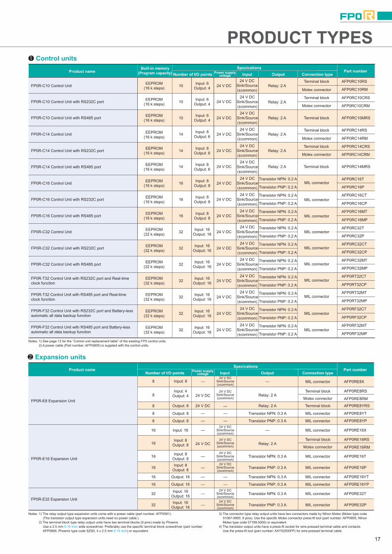

PRODUCT TYPES Intelligent units
Power supply unit and others
Link and communication units
Programming tools
Windows version tool softwareControl FPWIN GR (FP0R is compatible with Ver. 2.8 or later.)
Handheld programmer
Windows version tool softwareControl FPWIN Pro Ver.6 (Conforms to IEC61131-3)(FP0R is compatible with Ver. 6.1 or later.)
Japanese tool kit with cable
Not available for FP0R. Also the discontinued models (AFP1113V2 and AFP1114V2) are not compatible with FP0R. (They are compatible with FP0.)
AFPS50160
AFPS50560
AFPS10520
AFPS11520
AFPS10820
AFPS10920
CD-ROM for Windows, with cable (AFC8503)for connection of FP to DOS/V PC
CD-ROM for Windows
CD-ROM for Windows
CD-ROM for Windows
CD-ROM for Windows
CD-ROM for Windows
CD-ROM for Windows
AFPS10122
Options and maintenance parts
Japanese version, Full type
English version, Full type
English version, Full type
English version, Small type
Chinese version, Full type
Korean
Product name Specications Part number
Product name Specications Part number
Data clear type
Data hold type
Relay output type Necessary when wiring terminals block (Phoenix).
Necessary when wiring relay output type and Molex connectors. (MOLEX: 57189-5000)
Necessary when wiring transistor output type connectors.
Screw-stop attachment plate for FP0 expansion unit. Slim model.
Screw-stop attachment plate for FP0 control unit. Flat model.
Loose-wiring cable (9 leads) with molex socket attached at one end, AWG20, 0.5 mm2, 1 set: 2 cables (blue & white).
Loose-wiring cable (10 leads) with connectors attached at one end, AWG22, 0.3 mm2, 1 set: 2 cables (blue & white)
Length: 1 m 3.3 ft
Length: 3 m 9.8 ft
Length: 1 m 3.3 ft
Length: 3 m 9.8 ft
Flat cable connector set (10 leads)
Attaches to relay output and terminal block type. Maintenance part
Attaches to relay output and Molex connector types. Maintenance part
Attaches to transistor output type. Maintenance part
Attaches to expansion unit. Maintenance part Length: 1 m 3.3 ft
AFP8670FP Memory Loader (Note)
Terminal screwdriver
Molex connector pressure contact tool
Multi-wire connector pressure contact tool
FP0 Slim type Mounting plate
FP0 Flat type Mounting plate
Relay output Molex type I/O cable
Transistor output type I/O Cable
Flat cable connector set
Terminal socket
Molex socket
Wire-press socket
Power cable for expansion unit
AFP8671
AFP0806
AFP0805
AXY52000FP
AFP0803 (set for 10)
AFP0804 (set for 10)
AFP0551 (2 cables set)
AFP0553 (2 cables set)
AFP0521 (2 cables set)
AFP0523 (2 cables set)
AFP0808 (including 4 pieces)
AFP0802 (2 sokets per pack)
AFP0801 (2 sokets per pack)
AFP0807 (2 sokets per pack)
AFP0581 (1 cable per pack)
Attaches to FP0R control unit. Maintenance part Length: 1 m 3.3 ftPower cable for conrol unit AFPG805 (1 cable per pack)
Note: FP0R is compatible with Ver. 2 or later.
Input voltage: 100 to 240 V ACOutput capacity: 24 V DC, 0.7 A
Data clear type
AFP0634FP0-PSA4
AFP8670
Data hold type AFP8671
Product name Specications Part numberProduct number
FP Memory Loader
FP0 Power Supply Unit
AFP0480
AFP0401
AFP0420
AFP04123
AFP04121
AFP0421
FP0-A21
FP0-A80
FP0-TC4
FP0-A04I
FP0-A04V
FP0-TC8
Specications Part numberProduct number
K, J, T and R thermocouple, Resolution: 0.1°C
K, J, T and R thermocouple, Resolution: 0.1°C
<Input specifications>
<Output specifications>
<Input specifications>
<Output specifications>
Number or channels : 2 channelsInput range : Voltage 0 to 5 V, -10 to +10 V (Resolution: 1/4,000) Current 0 to 20 mA (Resolution: 1/4,000)
Number or channels : 1 channelOutput range : Voltage -10 to +10 V (Resolution: 1/4,000) Current 0 to 20 mA (Resolution: 1/4,000) Number or channels : 8 channelsInput range : Voltage 0 to 5 V, -10 to +10 V, -100 to 100 mV (Resolution: 1/4,000) Current 0 to 20 mA (Resolution: 1/4,000)
Number or channels : 4 channelsOutput range : (Voltage output type) -10 to +10 V (Resolution: 1/4,000) (Current output type) 4 to 20 mA (Resolution: 1/4,000)
FP0 Analog I/O Unit
FP0 A/D Converter Unit
FP0 D/A Converter Unit
FP0 Thermocouple Unit
Product name
AFP0794324 V DC FP0-CCLS
AFP073224 V DC
24 V DC
FP0-IOL
AKS1202
AFP8536100 to 240 V AC
AFP853224 V DC
AFP061124 V DC FP-WEB2
Specications Part numberProduct numberPower supplyvoltageProduct name
This unit is for making the FP0 function as a slave station of the CC-Link. Only one unit can be connected to the furthest right edge of the FP0 expansion bus.
Note: Accuracy will change if an FP0 thermocouple unit is used at the same time. For details, please refer to the catalog or to the CC-Link Unit manual.
This is a link unit designed to make the FP0 function as a station to MEWNET-F (remote I/O system).
RS232C/RS485 data can be easily monitored by LAN.
This is an RS485 adapter designed to allow use of the computer link function for connecting to a network-connected PLC via C-NET from a host computer.
Unit for connecting FP series or RS232C interface device and Ethernet Web-server function and E-mail sending function
FP0 CC-Link Slave Unit
FP0 I/O Link Unit
KS1 Signal Converter
C-NET Adapter (for computer side)
FP Web-Server 2 Unit
18 19

Programmable ControllerSERIESFP0R SERIES
X0X1X2X3X4X5X6X7
COM
Y0Y1Y2Y3
COMY4
COMY5
COM
X0X1X2X3
(NC)(NC)(NC)(NC)COM
Y0Y1Y2Y3
(NC)(NC)(NC)(NC)COM
Y0Y1Y2Y3Y4Y5Y6Y7
COM
C10RS/C10RM C14RS/C14RM E8RS/E8RM E16RS/E16RM/E8YRS
Y0Y1
(NC)(NC)COMY2
COMY3
COM
X0X1X2X3X4X5
(NC)(NC)COM
X0X1X2X3X4X5X6X7
COM
<Reference measuring for wiring> Terminal array
X 0 X 1X 2 X 3X 4 X 5X 6 X 7
COM COM
Input (8 points / common)
Y 0 Y 1Y 2 Y 3Y 4 Y 5Y 6 Y 7(+) (–)
Output (8 points / common)
SGRD
SD
<Reference measuring for wiring> Terminal array
Note: Two COM terminals on the input circuit are connected inside the unit.
RS232C port Terminal array
E−
+
RS485 port Terminal array
X 0 X 1X 2 X 3X 4 X 5X 6 X 7
COM COM
Input (16 points / common)
Y 0 Y 1Y 2 Y 3Y 4 Y 5Y 6 Y 7(+) (–)
Output (16 points / common)
X 8 X 9X A X BX C X DX E X F
COM COM
Y 8 Y 9YA Y BY C Y DY E Y F(+) (–)
SGRD
SD
<Reference measuring for wiring> Terminal array RS232C port Terminal array
E−
+
RS485 port Terminal array
<Reference measuring for wiring> <Reference measuring for wiring><Reference measuring for wiring> <Reference measuring for wiring>
(0.71) 2.36(18) 60.0
(9) (0.35) (0.30)
(7.5)
90.03.54
(Note 1)
DIN standard rail(DIN EN50022 35 mm 1.38 in width)
Front view
60.0
(67.5)
A + B + C + D dimensions (mm in)A A→B A→C A→D
30.01.182.36
(Note 2)
90.03.54
Input connector
Output connector
0.1460.03.5
RS232C port (C32C, T32C and F32C only)RS485 port (C32M, T32M, F32M only)
0.9825.0
Input connector
Output connector
RS232C port (C16C only)RS485 port (C16M only)
(Note 1)
DIN standard rail(DIN EN50022 35 mm 1.38 in width)
(0.39)(10)
DIN standard rail(DIN EN50022 35 mm 1.38 in width)
(Note 1)
Input terminal block
Output terminal block
RS232C port (C10CR and C14CR only)RS485 port (C10MR and C14MR only)
0.98
MODE
OFF ON
V 0
INI 0
COM
COM
FP0
- A21
OUT
V 1I 1
VI
12345
EXPANSIONCONNECTOR
2.36(0.39)25.0 60.0(10)
Notes: 1) DIN rail is attached on the center of the unit. 2) The AFP0RE8YRS is not equipped with an input terminal block.
Notes: 1) DIN rail is attached on the center of the unit. 2) The AFP0RE32T, AFP0RE32P, AFP0RE16X, AFP0RE16YT and AFP0RE16YP are
25 mm 0.98 in each. 3) The AFP0RE16X has no output connector. 4) The AFP0RE16YT and AFP0RE16YP has no input connector.
Notes: 1) Four COM terminals on the input circuit are connected inside the unit.
2) Two (+) terminals and two (-) terminals on the output circuit are connected respectively inside the unit.
Notes: 1) DIN rail is attached on the center of the unit. 2) The AFP0RE8X has no output connector. 3) The AFP0RE8YT and AFP0RE8YP has no input connector.
ERROR
RUN
PROG
ALARM
RUN
P ROG.
01
23
45
67
89
AB
CD
EF
01
23
45
67
89
AB
CD
EF
X8-FXO-7
01
23
45
67
89
AB
CD
EF
01
23
45
67
89
AB
CD
EF
X8-FXO-7
01
23
45
67
89
AB
CD
EF
01
23
45
67
89
AB
CD
EF
X8-FXO-7
01
23
45
67
89
AB
CD
EF
01
23
45
67
89
AB
CD
EF
X8-FXO-7
Y8-FYO-7 Y8-FYO-7 Y8-FYO-7 Y8-FYO-7
90.0
B C DA
(45)
(45)
2.36
(2.66)
3.54
(1.77)
(1.77)
Top view (with DIN rail attached)
C10RSC10CRSC10RMC10CRMC10MRSC14RSC14CRSC14RMC14CRMC14MRS
C32TC32CTC32PC32CPT32CTT32CPF32CTF32CP
C16TC16CTC16PC16CPC16MTC16MP
C32MTC32MPT32MTT32MPF32MTF32MP
Control unit 1 expansion unit connected
Control unit only
2 expansion units connected
3 expansion units connected
(0.18)(4.5)
(10)(0.39) 13.0
0.51
5.12130.0
approx.
5.12130.0
approx.
5.12130.0
approx.
Inpu
tO
utpu
t
Inputterminal
Connection terminalOutputterminal
0.98 1.97 2.95 3.94
1.18 2.17 3.15 4.13
25 50 75 100
30 55 80 105
90.03.54
0.9825
(0.39)(10)
2.3660.0
0.143.5
0.184.5
90.03.54
0.9825.0
0.338.50
2.3660.0
90.03.54
0.143.5
0.184.5
1.3835.0
0.7619.2
2.3660.0
0.143.5
90.03.54
0.143.5
2.3660.0
90.03.54
(0.71)(18)
2.3660.0
90.03.54
(0.18)(4.5)
(0.30) (7.5)
13.00.51
(10)(0.39)
(9) (0.35)
0.143.5
2.3660.0
0.9825.0
90.03.54
2.3660.0
90.03.54
(0.18)(4.5)
(0.30) (7.5)
13.00.51
(10)(0.39)
(9) (0.35)
DIMENSIONS Control units and Expansion units
Control units
Expansion units
FP Web-Server 2 Unit FP0 Power Supply Unit
External Dimensions During Expansions
FP0 Analog I/O Unit and D/A Converter Unit
FP0 A/D Converter Unit and Thermocouple Unit
(Unit: mm in)
* For the relay output type, the terminal block type is listed as the representative type.
C10RS, C10RM, C10CRS, C10CRM, C10MRS,C14RS, C14RM, C14CRS, C14CRM and C14MRS
E8RS, E8RM, E8YRS, E16RS and E16RM
Control units
Expansion units
C16T, C16P, C16CT, C16CP, C16MT and C16MP
E16T, E16P, E8X, E8YT and E8YP
Control units
Expansion units
C32T, C32CT, C32P, C32CP, C32MT, C32MP,T32CT, T32CP, T32MT, T32MP,F32CT, F32CP, F32MT and F32MP
E32T, E32P, E16X, E16YT and E16YP
RecognitionConforming to EMC Directive Listing
The New Standard of Ultra-compact PLCs
*1. Among compact PLCs with up to 128 I/O points based on our research as of July 1, 2011*2. Based on our research as of July 1, 2011
Equipped with RS485 Port
Multi-axis Control available without Expansion
NEW
Large Capacity Program and Data Memory
Largest in its class *1
Ultra-high Speed ProcessingFastest in its class *1
Battery-less Automatic Backup of All Data
Industry’s First *2
2011.08 panasonic-electric-works.net/sunx
Panasonic Electric Works SUNX Co., Ltd.Global Sales & Marketing Division
2431-1 Ushiyama-cho, Kasugai-shi, Aichi, 486-0901, JapanTelephone: +81-568-33-7861 Facsimile: +81-568-33-8591
All Rights Reserved ©Panasonic Electric Works SUNX Co., Ltd. 2011
2011.08 panasonic-electric-works.net/sunx
No. CE-FP0R-9 August, 2011