the new atsc 3.0 television...
TRANSCRIPT

THE NEW ATSC 3.0
TELEVISION STANDARD
DENNIS WALLACE
MANAGING PARTNER
Radio Club of America Technical Symposium
Pittsburgh, PA
November 13, 2017
AGENDA
1. Overview of ATSC 3.0 Standard
2. Unique System Characteristics of ATSC 3.0
3. Upper Layers of System
4. RF (Physical) Layer of ATSC 3.0 System
5. Market Transition From ATSC 1.0 to ATSC 3.0
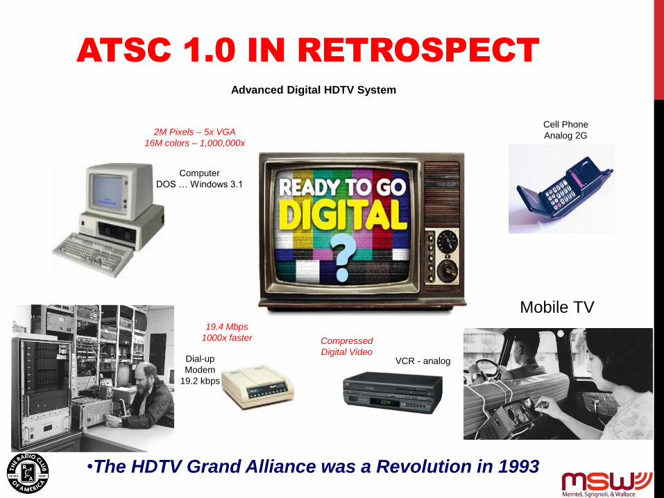
ATSC 1.0 IN RETROSPECT
•The HDTV Grand Alliance was a Revolution in 1993
Dial-up
Modem
19.2 kbps
Cell Phone
Analog 2G
VCR - analog
Computer
DOS … Windows 3.1
Advanced Digital HDTV System
Advanced Digital HDTV System
19.4 Mbps
1000x faster Compressed
Digital Video
Wireless
Digital
2M Pixels – 5x VGA
16M colors – 1,000,000x
Mobile TV
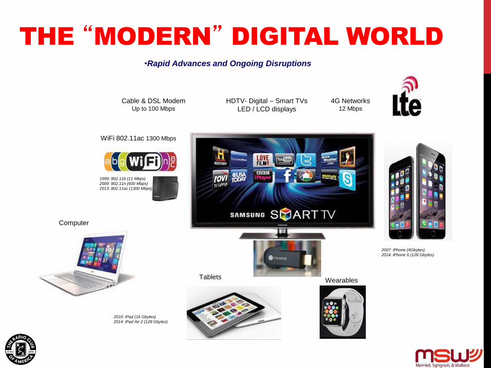
THE “MODERN” DIGITAL WORLD
Cable & DSL Modem Up to 100 Mbps
HDTV- Digital – Smart TVs
LED / LCD displays
SmartPhones WiFi 802.11ac 1300 Mbps
2007: iPhone (4Gbytes)
2014: iPhone 6 (128 Gbytes)
2010: iPad (16 Gbytes)
2014: iPad Air 2 (128 Gbytes)
Tablets
1999: 802.11b (11 Mbps)
2009: 802.11n (600 Mbps)
2013: 802.11ac (1300 Mbps)
Computer
4G Networks 12 Mbps
Wearables
•Rapid Advances and Ongoing Disruptions
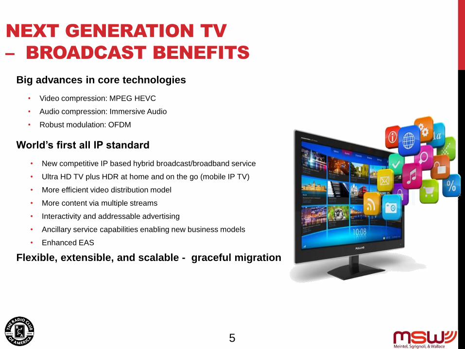
NEXT GENERATION TV
– BROADCAST BENEFITS
Big advances in core technologies
• Video compression: MPEG HEVC
• Audio compression: Immersive Audio
• Robust modulation: OFDM
World’s first all IP standard
• New competitive IP based hybrid broadcast/broadband service
• Ultra HD TV plus HDR at home and on the go (mobile IP TV)
• More efficient video distribution model
• More content via multiple streams
• Interactivity and addressable advertising
• Ancillary service capabilities enabling new business models
• Enhanced EAS
Flexible, extensible, and scalable - graceful migration
5

ATSC 3.0 LAYER STACK
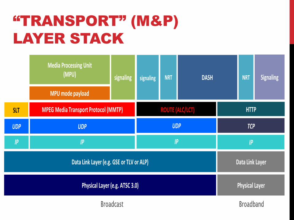
“TRANSPORT” (M&P)
LAYER STACK
signaling DASH
Media Processing Unit (MPU)
MPU mode payload
ROUTE (ALC/LCT)MPEG Media Transport Protocol (MMTP)
IP
Physical Layer (e.g. ATSC 3.0)
SignalingNRT
HTTP
TCP
Physical Layer
UDP
Data Link Layer (e.g. GSE or TLV or ALP)
Broadcast Broadband
Data Link Layer
IPIP
UDP
SLT
signaling NRT
IP
UDP

TRANSMISSION
ATSC 1.0
• One bit rate – 19.39 Mbps
• One coverage area
• Service flexibility – HDTV,
multicast, data (see next slide)
8-VSB
19.4
Mbps

TRANSMISSION
ATSC 1.0
• One bit rate – 19.39 Mbps
• One coverage area
• Service flexibility – HDTV, multicast, data
(see next slide)
8-VSB
19.4
Mbps
4 Mbps
2 Mbps
9 Mbps
6
Mbps
• Flexible bit rate & coverage area choices
• Optional on-channel repeaters for robust
indoor & mobile reception over entire DMA
• Multiple simultaneous “bit pipes” –
different choices for different broadcast
services • Physical Layer Pipes (time)
• Layer Division Multiplexing (power)
• Channel Bonding
ATSC 3.0
More Bits To More Places
Repeater
Repeater
Repeater
AND
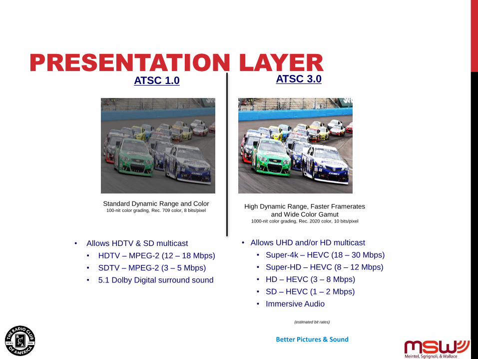
ATSC 1.0
• Allows HDTV & SD multicast
• HDTV – MPEG-2 (12 – 18 Mbps)
• SDTV – MPEG-2 (3 – 5 Mbps)
• 5.1 Dolby Digital surround sound
Standard Dynamic Range and Color 100-nit color grading, Rec. 709 color, 8 bits/pixel
Better Pictures & Sound
ATSC 3.0
• Allows UHD and/or HD multicast
• Super-4k – HEVC (18 – 30 Mbps)
• Super-HD – HEVC (8 – 12 Mbps)
• HD – HEVC (3 – 8 Mbps)
• SD – HEVC (1 – 2 Mbps)
• Immersive Audio
High Dynamic Range, Faster Framerates
and Wide Color Gamut 1000-nit color grading, Rec. 2020 color, 10 bits/pixel
(estimated bit rates)
PRESENTATION LAYER
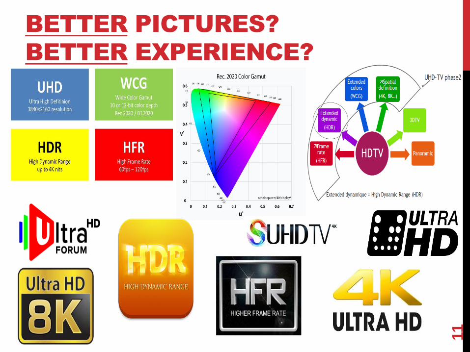
BETTER PICTURES?
BETTER EXPERIENCE?
11

HIGHER RESOLUTION? –OR- MORE
CHANNELS?

VIDEO COMPRESSION COMPARISON FOR SIMILAR PICTURE QUALITY
ATSC 1.0
(MPEG-2 Video)
ATSC 3.0
(MPEG-H HEVC)
SD 3 - 5 Mbps 1 - 1.8 Mbps
HD 10 - 18 Mbps 2.5 - 4.5 Mbps
4K UHDTV
(2160p60 10b)
N/A 8 – 15 Mbps*
15 – 25 Mbps**
*For typical PQ comparisons
**For higher PQ expectations
As with all bitrate projections, these ranges are subject to PQ expectations & content complexity
Bitrate table courtesy of Matthew Goldman, Ericsson

AUDIO COMPRESSION COMPARISON FOR SIMILAR AUDIO QUALITY
ATSC 1.0
(Dolby AC-
3)
ATSC 3.0
(Dolby AC-4 or MPEG-
H Audio)
Stereo 192 kbps 32 – 96 kbps
Surround (5.1) 384 kbps 80 – 208 kbps
Immersive (>7.1+4 ch.
+ objects) &
Personalizable N/A
144 – 384 kbps* 288 – 768 kbps**
*For “basic” immersive
**For “advanced” immersive
As with all bitrate projections, these ranges are subject to audio quality expectations & content complexity

ATSC 3.0
BROADCASTING
~ Six-Eight 1080 ‘fixed’ HDTV Services*
~ Twelve 720 ‘fixed’ HDTV Services**
1080P
HDTV
1080P
HDTV
1080P
HDTV
1080P
HDTV
1080P
HDTV
1080P
HDTV
1080P
HDTV
1080P
HDTV
720P
HDTV
720P
HDTV
720P
HDTV
720P
HDTV
720P
HDTV
720P
HDTV
720P
HDTV
720P
HDTV
720P
HDTV
720P
HDTV
720P
HDTV
720P
HDTV
* 2TB of storage = 1,300 hours
** 2TB of storage = 2,000 hours

ATSC 3.0
BROADCASTING
Fifteen or more 480p “Nomadic” Services*
Thirty or more 360p “Nomadic” fully mobile Services**
…or variety of combined “fixed & Mobile” video services
EDTV EDTV EDTV EDTV EDTV EDTV EDTV EDTV EDTV EDTV EDTV EDTV
EMDTV
EDTV EDTV
EDTV EDTV
EMDTV EMDTV EMDTV EMDTV EMDTV EMDTV EMDTV EMDTV EMDTV EMDTV EMDTV
EMDTV EMDTV EMDTV EMDTV EMDTV EMDTV EMDTV EMDTV EMDTV EMDTV EMDTV EMDTV
EMDTV EMDTV
EMDTV EMDTV 720P
HDTV
720P
HDTV
720P
HDTV
720P
HDTV
SDT
V
SDT
V
SDT
V
SDT
V
MDTV
MDTV
MDTV
MDTV
* 2TB of storage = 6,000hours
** 2TB of storage = 10,000 hours
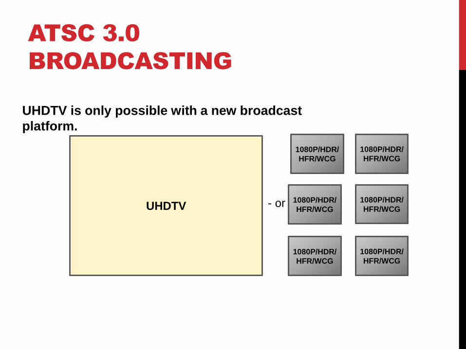
ATSC 3.0
BROADCASTING
UHDTV is only possible with a new broadcast
platform.
UHDTV
1080P/HDR/
HFR/WCG
- or -
1080P/HDR/
HFR/WCG
1080P/HDR/
HFR/WCG
1080P/HDR/
HFR/WCG
1080P/HDR/
HFR/WCG
1080P/HDR/
HFR/WCG

SCALABLE VIDEO CODING
Allows multiple devices to decode various picture
quality/resolutions from video stream
• Robust HDTV Stream
• Less Robust Enhancement Layer Video Stream
Business motivation to utilize SVC as well as quality and
service motivations.
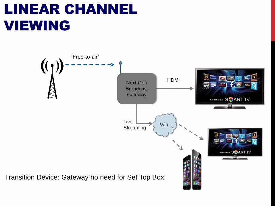
PC
HDMI
Live
Streaming
‘Free-to-air’
Next Gen
Broadcast
Gateway
Wifi
LINEAR CHANNEL
VIEWING
Transition Device: Gateway no need for Set Top Box

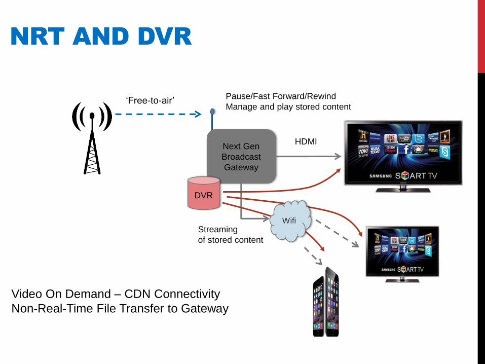
PC
HDMI
Live
Streaming
‘Free-to-air’ UHD
Next Gen
Broadcast
Gateway
Wifi
HD
MULTIPLE CHANNELS AND
FORMATS
PC
Next Gen
Broadcast
Gateway
HDMI
Streaming
of stored content
‘Free-to-air’
DVR
Pause/Fast Forward/Rewind
Manage and play stored content
Wifi
NRT AND DVR
Video On Demand – CDN Connectivity
Non-Real-Time File Transfer to Gateway
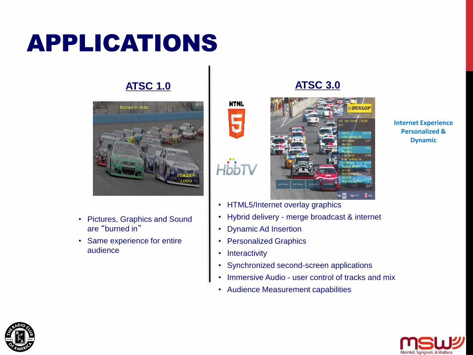
ATSC 1.0
• Pictures, Graphics and Sound
are “burned in”
• Same experience for entire
audience
Station Logo
Burned-in Stats
ATSC 3.0
• HTML5/Internet overlay graphics
• Hybrid delivery - merge broadcast & internet
• Dynamic Ad Insertion
• Personalized Graphics
• Interactivity
• Synchronized second-screen applications
• Immersive Audio - user control of tracks and mix
• Audience Measurement capabilities
Internet Experience Personalized &
Dynamic
APPLICATIONS

NEW PUBLIC SERVICE
CAPABILITIES
• Emergency Alerting
• Extremely robust EAS “wake up” signaling
• Advanced EAS messaging capabilities
• Ability to reach indoor, battery-powered receivers
• Robust Audio and Closed-Caption delivery even when picture fails
• Improved audio intelligibility for the hearing impaired
• New capabilities for improved dialog/narrative intelligibility
(track – specific volume control)
• Continued support for Video Description Services
ATSC 3.0
PHYSICAL LAYER
OVERVIEW AND KEY TECHNOLOGIES

ATSC 1.0 TRANSMISION MODE
• Single Set of Transmission Parameters for Over the Air Broadcasting
• 8-VSB Used for Terrestrial TV (2VSB, 4VSB, 16VSB generally not in use)
• Vestigial Sideband AM
• One Carrier
• 8 Amplitude Levels
• ~15dB Threshold for AWGN
• 2/3 FEC
• One Fixed Data Rate 19.39MB/Sec Payload
• Framing Based upon MPEG TS Packets
• Echo Cancellation in Receiver ~ 100uSec
• Small Pilot Carrier
• One Interleaver
• Single Purpose Transmission System
• Fixed antenna TV service
• “Replacement” for Analog Fixed Service
Single Blade Swiss Army Knife

ATSC 3.0 TRANSMISSION MODES • Low Density Parity Check Codes – Long /Short
• Forward Error Correction Code Rates (Inner)
• 12 Code Rates – 2/15 thru 13/15
• Three Choices for Outer Code BCH, CRC, None
• Modulation Constellations – 6 Choices
• One Uniform Constellation • QPSK
• Five Non-Uniform Constellations • 16QAM 2D NUC
• 64QAM 2D NUC
• 256QAM 2D NUC
• 1024QAM 1D NUC
• 4096QAM 1D NUC
• Three FFT Choices
• 8K, 16K, 32K
• Pilot Patterns
• 16 Pilot Patterns
• Guard Intervals
• 12 Guard Intervals (7 for all FFT’s and 5 for 16K/32K FFT Only)
• Range from 27.78uSec to 703.7uSec
• Time Interleavers
• Convolutional Interleaver (S-PLP)
• Hybrid Interleaver (M-PLP)
• Framing – Frame Length Variable 50mSec – 5Sec
• Time Division Multiplexing
• Layer Division Multiplexing
• Frequency Division Multiplexing
The Ultimate Swiss Army Knife

ATSC 3.0 RANGE OF PERFORMANCE
• System Synchronization and Signaling (Bootstrap)
• AWGN SNR Threshold ~ -10dB
• Rayleigh Channel SNR ~ -6dB
• Preamble and Payload Data Threshold Dependent Upon Parameter Choices
• AWGN SNR Threshold Variable -6dB to +32dB
• Rayleigh Channel SNR Approximately -5dB to +36dB
• Payload Data Rate Dependent Upon Parameter Choices
• QPSK – Most Robust Mode ~ 1MB/Sec
• 2/15 FEC; 8K FFT
• 4096 QAM – Least Robust Mode ~ 57MB/sec
• 13/15 FEC; 32K FFT
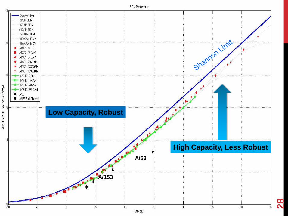
A/53
Low Capacity, Robust
High Capacity, Less Robust
A/153
28
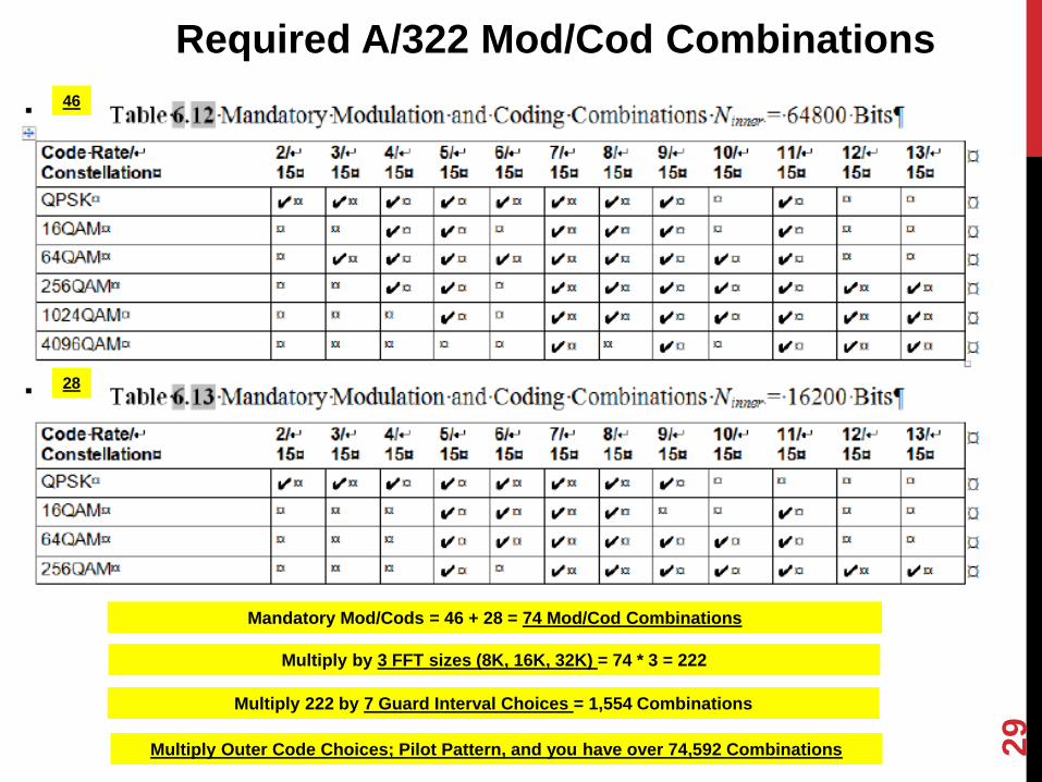
Required A/322 Mod/Cod Combinations
Mandatory Mod/Cods = 46 + 28 = 74 Mod/Cod Combinations
46
28
Multiply by 3 FFT sizes (8K, 16K, 32K) = 74 * 3 = 222
Multiply 222 by 7 Guard Interval Choices = 1,554 Combinations
Multiply Outer Code Choices; Pilot Pattern, and you have over 74,592 Combinations 29

CONSTELLATIONS
Enable multiple constellation types
• Non-uniform 16/64/256/1024/4096 point constellations + QPSK
• Non-uniform constellations • can give more than 1dB gain vs. uniform constellations
1024QAM NUC CR=6/15
16-QAM NUC CR=6/15
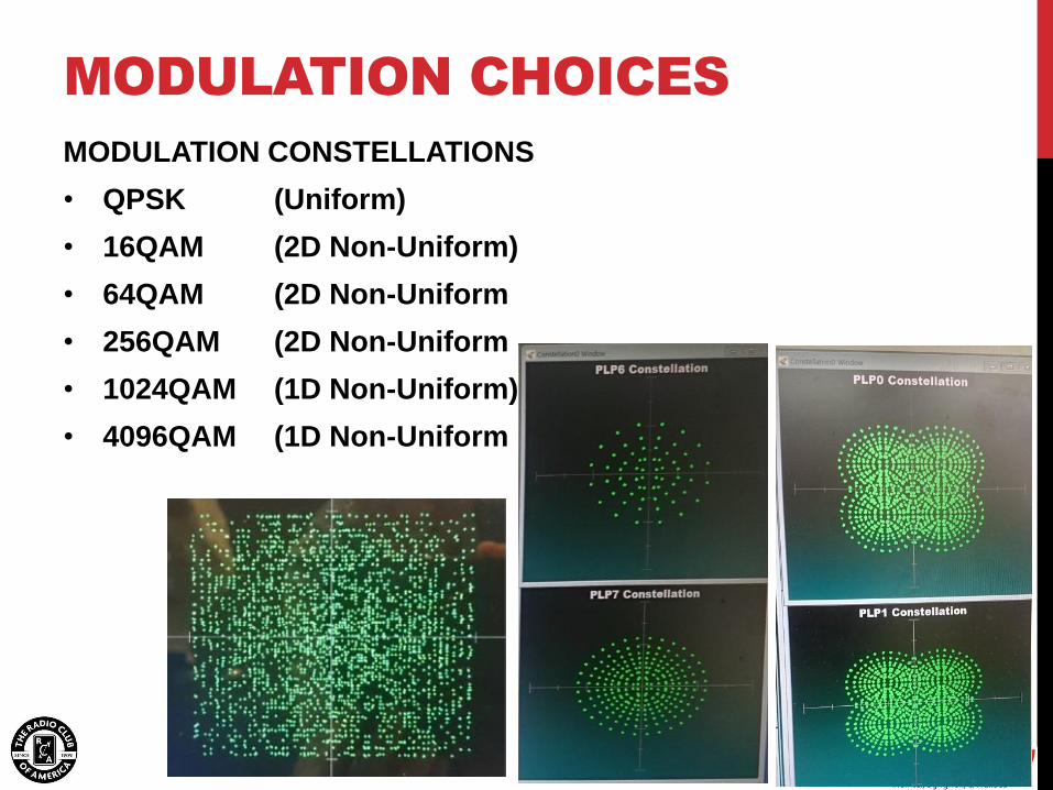
MODULATION CHOICES
MODULATION CONSTELLATIONS
• QPSK (Uniform)
• 16QAM (2D Non-Uniform)
• 64QAM (2D Non-Uniform
• 256QAM (2D Non-Uniform
• 1024QAM (1D Non-Uniform)
• 4096QAM (1D Non-Uniform
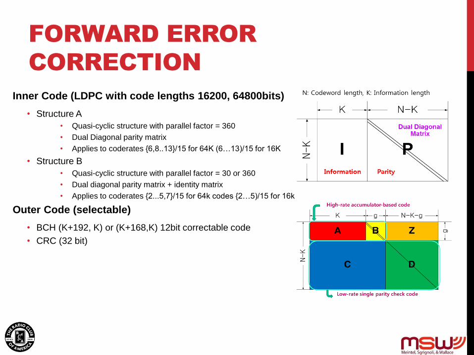
FORWARD ERROR
CORRECTION
Inner Code (LDPC with code lengths 16200, 64800bits)
• Structure A
• Quasi-cyclic structure with parallel factor = 360
• Dual Diagonal parity matrix
• Applies to coderates {6,8..13}/15 for 64K (6…13)/15 for 16K
• Structure B
• Quasi-cyclic structure with parallel factor = 30 or 360
• Dual diagonal parity matrix + identity matrix
• Applies to coderates {2...5,7}/15 for 64k codes {2…5)/15 for 16k
Outer Code (selectable)
• BCH (K+192, K) or (K+168,K) 12bit correctable code
• CRC (32 bit)

LDM is a new transmission scheme that uses spectrum
overlay technology to super-impose multiple physical
layer data streams with different power levels, error
correction codes and modulations for different services and
reception environments;
For each LDM layer, 100% of the RF bandwidth and
100% of the time are used to transmit the multi-layered
signals for spectrum efficiency and flexible use of the
spectrum;
Signal cancellation can be used to retrieve the robust
upper layer signal first, cancel it from the received signal,
and then start the decoding of lower layer signal;
The upper layer (UL) is ultra-robust and well suited for HD portable, indoor,
mobile reception. The high data rate lower layer (LL) transmission system is
well suited for multiple-HD and 4k-UHD high data rate fixed reception.
Future Extension Layer (FEL) can be added later with full backward
compatibility.
LDM overlay spectrum
RF
Channel
BW
5 dB
Upper
Layer
5 dB
Lower
Layer
Future
Extension
Layer
Layered Division Multiplexing (LDM)
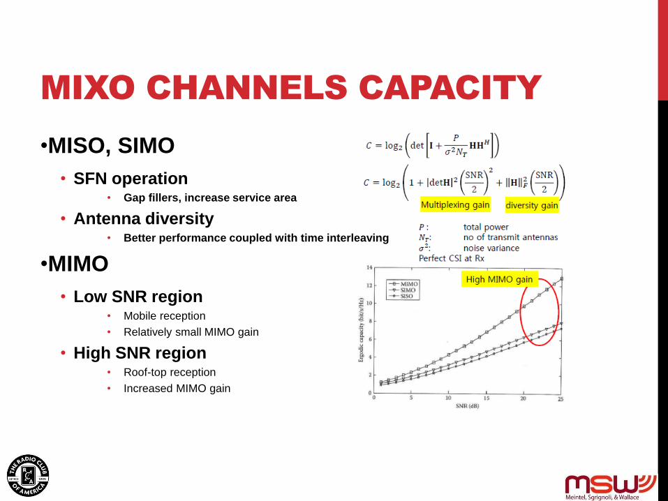
MIXO CHANNELS CAPACITY
•MISO, SIMO
• SFN operation • Gap fillers, increase service area
• Antenna diversity • Better performance coupled with time interleaving
•MIMO
• Low SNR region • Mobile reception
• Relatively small MIMO gain
• High SNR region • Roof-top reception
• Increased MIMO gain
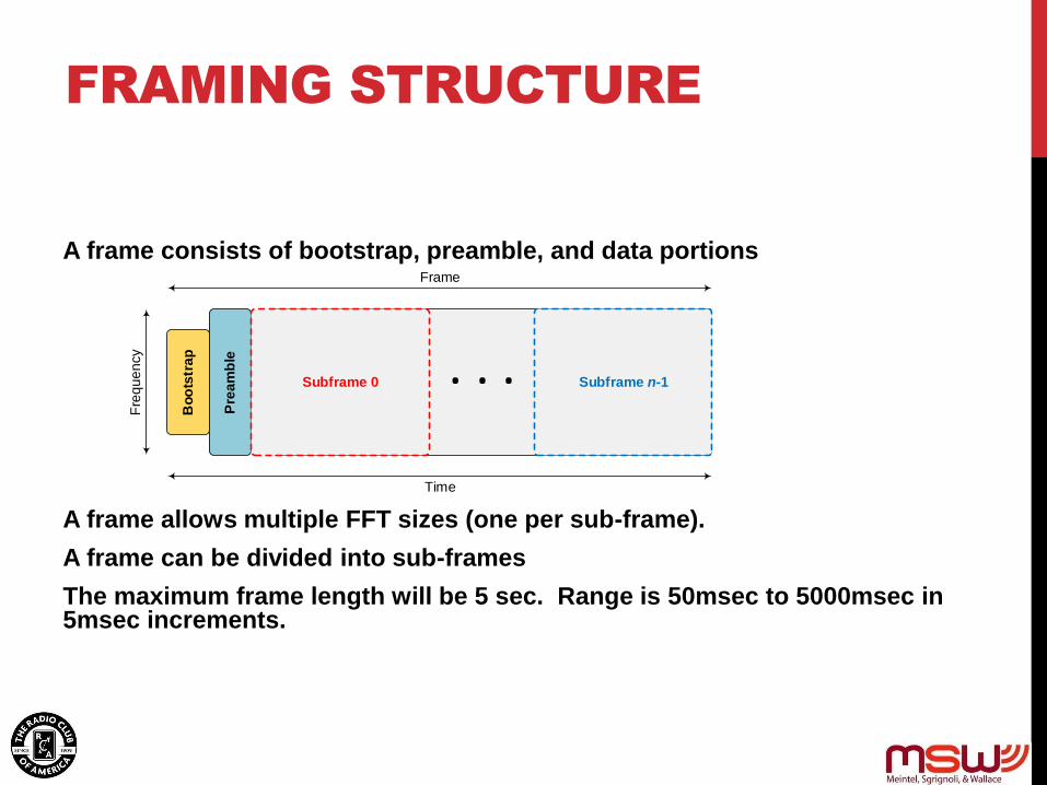
FRAMING STRUCTURE
A frame consists of bootstrap, preamble, and data portions
A frame allows multiple FFT sizes (one per sub-frame).
A frame can be divided into sub-frames
The maximum frame length will be 5 sec. Range is 50msec to 5000msec in 5msec increments.
Bo
ots
tra
p
Pre
am
ble
Time
Fre
qu
en
cy
Frame
Subframe 0 Subframe n-1. . .
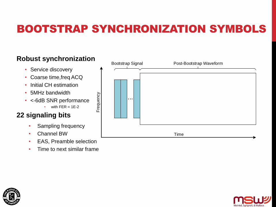
BOOTSTRAP SYNCHRONIZATION SYMBOLS
Robust synchronization
• Service discovery
• Coarse time,freq ACQ
• Initial CH estimation
• 5MHz bandwidth
• <-6dB SNR performance • with FER = 1E-2
22 signaling bits
• Sampling frequency
• Channel BW
• EAS, Preamble selection
• Time to next similar frame
Time
Fre
qu
en
cy
Bootstrap Signal Post-Bootstrap Waveform
...

SUB-FRAME TYPES
The sub-frame is a set of OFDM symbols with the same waveform attributes.
The waveform attributes of a sub-frame constitute a sub-frame type and are
defined as :
• FFT Size
• GI Duration
• Pilot Pattern
• SISO/MIMO
• Frequency INTL
• NoC
In one frame,
• Multiple Sub-frames of different sub-frame type are allowed
• Multiple Sub-frames of the same sub-frame type are allowed
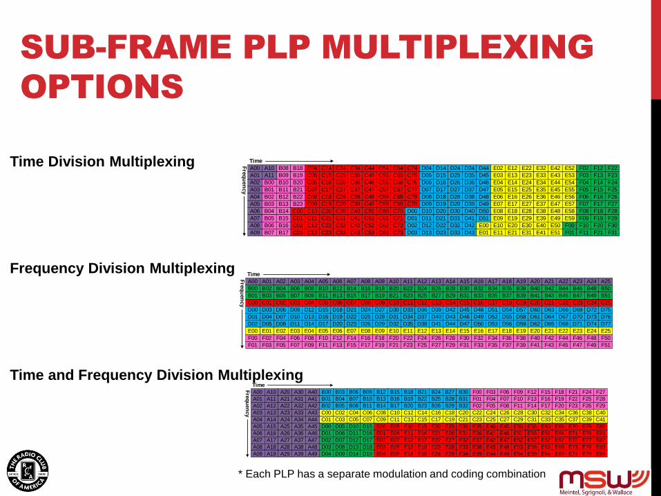
SUB-FRAME PLP MULTIPLEXING
OPTIONS
Time Division Multiplexing
Frequency Division Multiplexing
Time and Frequency Division Multiplexing
A00
A01
A02
A03
A04
A05
A06
A07
A08
A09
B00
B01
B02
B03
B04
B05
B06
B07
B08
B09
C00
C01
C02
C03
C04
C05
C06
C07
C08
C09
C10
C11
C12
C13
C14
C15
C16
C17
C18
C19
C20
C21
C22
C23
C24
C25
C26
C27
C28
C29
C30
C31
C32
C33
C34
C35
C36
C37
C38
C39
C40
C41
C42
C43
C44
C45
C46
C47
C72
C73
C74
C75
C76
C77
C78
C79
C56
C57
C58
C59
C60
C61
C62
C63
C64
C65
C66
C67
C68
C69
C70
C71
C48
C49
C50
C51
C52
C53
C54
C55
D00
D01
D02
D03
D04
D05
D06
D07
D08
D09
D10
D11
D12
D13
D14
D15
D16
D17
D18
D19
D20
D21
D22
D23
D24
D25
D26
D27
D28
D29
D30
D31
D32
D33
D34
D35
D36
D37
D40
D41
D42
D43
D44
D45
D46
D47
D48
D49
D50
D51
D38
D39
E01
E02
E03
E04
E05
E06
E07
E08
E09
E10
E11
E12
E13
E14
E15
E16
E17
E18
E19
E20
E21
E22
E23
E24
E25
E00
E26
E27
E28
E29
E31
E32
E33
E34
E35
E36
E37
E38
E39
E40
E41
E42
E43
E44
E45
E46
E47
E48
E49
E50
E51
E52
E53
E54
E55
E30
E56
E57
E58
E59
F00
F01
F02
F03
F04
F05
F06
F07
F08
F09
F10
F11
F12
F13
F14
F15
F16
F17
F18
F19
F20
F21
F22
F23
F24
F25
F26
F27
F28
F29
F30
F31
Time
Fre
qu
en
cy
B10
B11
B12
B13
B14
B15
B16
B17
B18
B19
B20
B21
B22
B23
A10
A11
A00 A01 A02 A03 A04 A05 A06 A07 A08 A09
B00
B01
B02
B03
B04
B05
B06
B07
B08
B09
C00 C01 C02 C03 C04 C05 C06 C07 C08 C09 C10 C11 C12 C13 C14 C15 C16 C17 C18 C19 C20 C21 C22 C23 C24 C25
D00
D01
D02
D03
D04
D05
D06
D07
D08
D09
D10
D11
D12
D13
D14
D15
D16
D17
D18
D19
D20
D21
D22
D23
D24
D25
D26
D27
D28
D29
D30
D31
D32
D33
D34
D35
D36
D37 D40
D41
D42
D43
D44
D45
D46
D47
D48
D49
D50
D51
D38
D39
E01 E02 E03 E04 E05 E06 E07 E08 E09 E10 E11 E12 E13 E14 E15 E16 E17 E18 E19 E20 E21 E22 E23 E24 E25E00
F00
F01
F02
F03
F04
F05
F06
F07
F08
F09
F10
F11
F12
F13
F14
F15
F16
F17
F18
F19
F20
F21
F22
F23
F24
F25
F26
F27
F28
F29
F30
F31
Time
Fre
qu
en
cy
B10
B11
B12
B13
B14
B15
B16
B17
B18
B19
B20
B21
B22
B23
A10 A11 A12 A13 A14 A15 A16 A17 A18 A19 A20 A21 A22 A23 A24 A25
F32
F33
F34
F35
F36
F37
F38
F39
F40
F41
F42
F43
F44
F45
F46
F47
F48
F49
F50
F51
B24
B25
B26
B27
B28
B29
B30
B31
B32
B33
B34
B35
B36
B37
B38
B39
B40
B41
B42
B43
B44
B45
B46
B47
B48
B49
B50
B51
D52
D53
D54
D55
D56
D57
D58
D59
D60
D61
D62
D63
D64
D65
D66
D67 D70
D71
D72
D73
D74
D75
D76
D77D68
D69
A00 B00 F00
C01
D00 E00
D01
D02
D03
C02
D04
D05
D06
D07
C03
D08
D09
D10
D11
C04
D12
D13
D14
D15
C05
C06
C07
C08
C09
C10
C11
C12
C13
C14
C15
C16
C17
C18
C19
C20
C21
C22
C23
C24
C25
C00
E01
E02
E03
E04
E05
E06
E07
E08
E09
E10
E11
E12
E13
E14
E15
E16
E17
E18
E19
E20
E21
E22
E23
E24
E25
E26
E27
E28
E29
E30
E31
E32
E33
E34
E35
E36
E37
E38
E39
E40
E41
E42
E43
E44
E45
E46
E47 E72
E73
E74
E75
E76
E77
E78
E79
E80
E81
E82
E83
E84
E56
E57
E58
E59
E60
E61
E62
E63
E64
E65
E66
E67
E68
E69
E70
E71
E48
E49
E50
E51
E52
E53
E54
E55
A01 B01
B02
B03
B04
B05
B06
B07
B08
B09
B10
B11
B12
B13
B14
B15
B16
B17
B18
B19
B20
B21
B22
B23
B24
B25
B26
B27
B28
B29
B30
B31
B32
F01
F02
F03
F04
F05
F06
F07
F08
F09
F10
F11
F12
F13
F14
F15
F16
F17
F18
F19
F20
F21
F22
F23
F24
F25
F26
F27
F28
F29A02
A03
A04
A05
A06
A07
A08
A09
A10
A11
A12
A13
A14
A15
A16
A17
A18
A19
A20
A21
A22
A23
A24
A25
A26
A27
A28
A29
A30
A31
A32
A33
A34
A35
A36
A37
A38
A39
A40
A41
A42
A43
A44
A45
A46
A47
A48
A49
Time
Fre
qu
en
cy C26
C27
C28
C29
C30
C31
C32
C33
C34
C35
C36
C37
C38
C39
C40
C41
D16
D17
D18
D19
* Each PLP has a separate modulation and coding combination
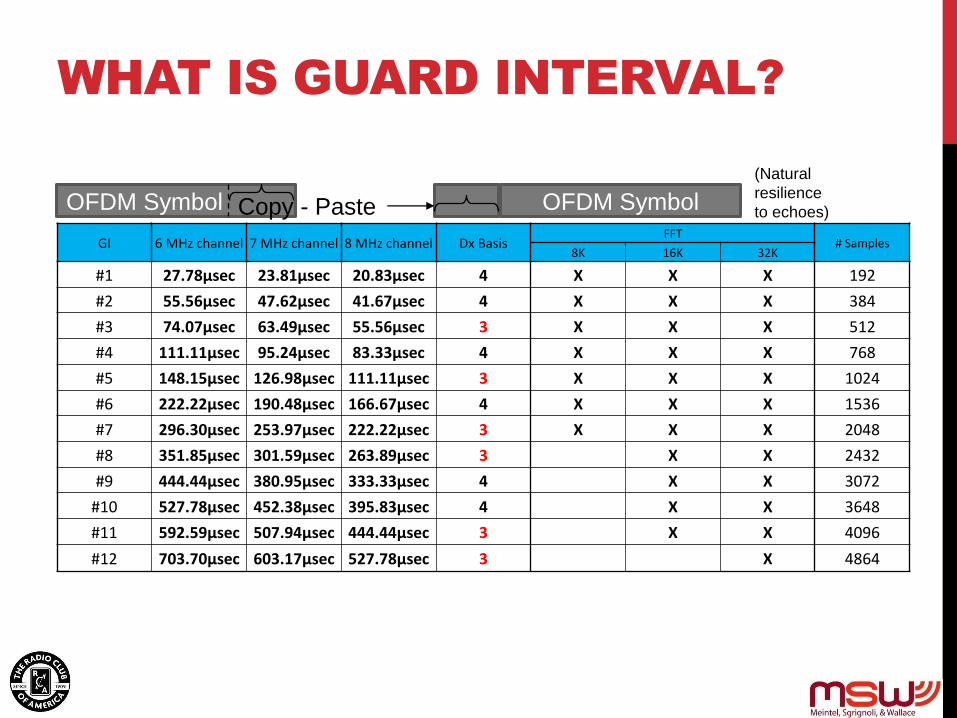
WHAT IS GUARD INTERVAL?
GI 6 MHz channel 7 MHz channel 8 MHz channel Dx Basis FFT
# Samples 8K 16K 32K
#1 27.78µsec 23.81µsec 20.83µsec 4 X X X 192
#2 55.56µsec 47.62µsec 41.67µsec 4 X X X 384
#3 74.07µsec 63.49µsec 55.56µsec 3 X X X 512
#4 111.11µsec 95.24µsec 83.33µsec 4 X X X 768
#5 148.15µsec 126.98µsec 111.11µsec 3 X X X 1024
#6 222.22µsec 190.48µsec 166.67µsec 4 X X X 1536
#7 296.30µsec 253.97µsec 222.22µsec 3 X X X 2048
#8 351.85µsec 301.59µsec 263.89µsec 3 X X 2432
#9 444.44µsec 380.95µsec 333.33µsec 4 X X 3072
#10 527.78µsec 452.38µsec 395.83µsec 4 X X 3648
#11 592.59µsec 507.94µsec 444.44µsec 3 X X 4096
#12 703.70µsec 603.17µsec 527.78µsec 3 X 4864
OFDM Symbol Copy - Paste OFDM Symbol
(Natural
resilience
to echoes)

ATSC 3.0 SINGLE
FREQUENCY NETWORKS
SFN BENEFITS
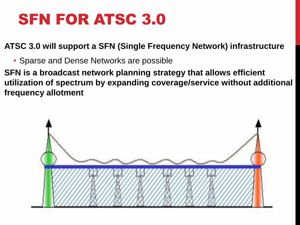
SFN FOR ATSC 3.0
ATSC 3.0 will support a SFN (Single Frequency Network) infrastructure
• Sparse and Dense Networks are possible
SFN is a broadcast network planning strategy that allows efficient
utilization of spectrum by expanding coverage/service without additional
frequency allotment

IMPACT OF SFN ON SERVICE
Total received signal strength may increase coverage in
overlapping region providing ‘SFN Gain’
• Indoor reception with simple receivers and antennas
• Better service inside of coverage contours including deep building
penetration
• Geographic (SFN zoned) services
• Interference mitigation
• Rx Path Diversity is biggest component of gain

SFN GAIN AND SPATIAL DIVERSITY PROVIDE
IMPROVED QOS
SFN provides increased service area for services
• Pedestrian, Mobile, Indoor
• Increased gains possible with MISO/receiver diversity
• Path Diversity provides real system gain
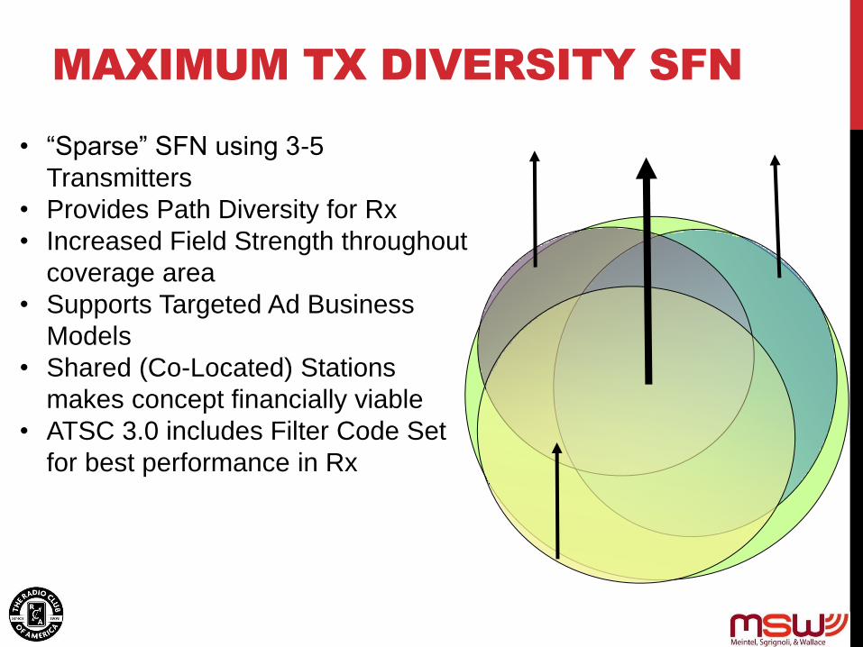
MAXIMUM TX DIVERSITY SFN
• “Sparse” SFN using 3-5
Transmitters
• Provides Path Diversity for Rx
• Increased Field Strength throughout
coverage area
• Supports Targeted Ad Business
Models
• Shared (Co-Located) Stations
makes concept financially viable
• ATSC 3.0 includes Filter Code Set
for best performance in Rx
HOW TO TRANSITION TO ATSC 3.0?
IP upgrade to Next Gen TV (3.0) – Fundamentally different than the
earlier DTV transition:
• Digital to digital upgrade
• No request for a second channel
• No request for government funded set-top-box converter
• Propose initial voluntary update: no government mandate and marketplace will
decide
• Optional for the consumer to upgrade to Next Gen TV
• New sets will support both 1.0 and 3.0 for a limited time
• Will coexist with the current 1.0 standard (utilizing channel sharing) so no
disruption to consumer viewing on current 1.0 sets
• Last transition

MARKET TRANSITION TO ATSC 3.0
• FCC Rules for Broadcasters November 16th
• “Voluntary” Operation of ATSC 3.0
• Adoption of ATSC 3.0 will be Market Driven
• No Governmental Tuner Mandates
• TV set manufacturers have pledged to make
sets ATSC 1/3 compatible
• Transition requires unprecedented cooperation
among broadcasters in each TV Market
• Key to transition is “Channel Sharing”
• Industry Consolidation & Joint Ventures are key
drivers

STATION TRANSITION CONCEPT
• FCC will not provide additional spectrum to manage transition (unlike analog to digital transition)
• Congress will not provide subsidy for converter boxes (unlike analog to digital transition)
• Industry will ask FCC to allow broadcasters to begin ATSC 3.0 on their own timetable—initially, all voluntary and market driven
• Will Coincide with Auction Re-Pack
• Stations will partner with each other to share spectrum
• Commercial launch and growth of ATSC 3.0 services while maintaining a limited service to ATSC 1.0 legacy viewers
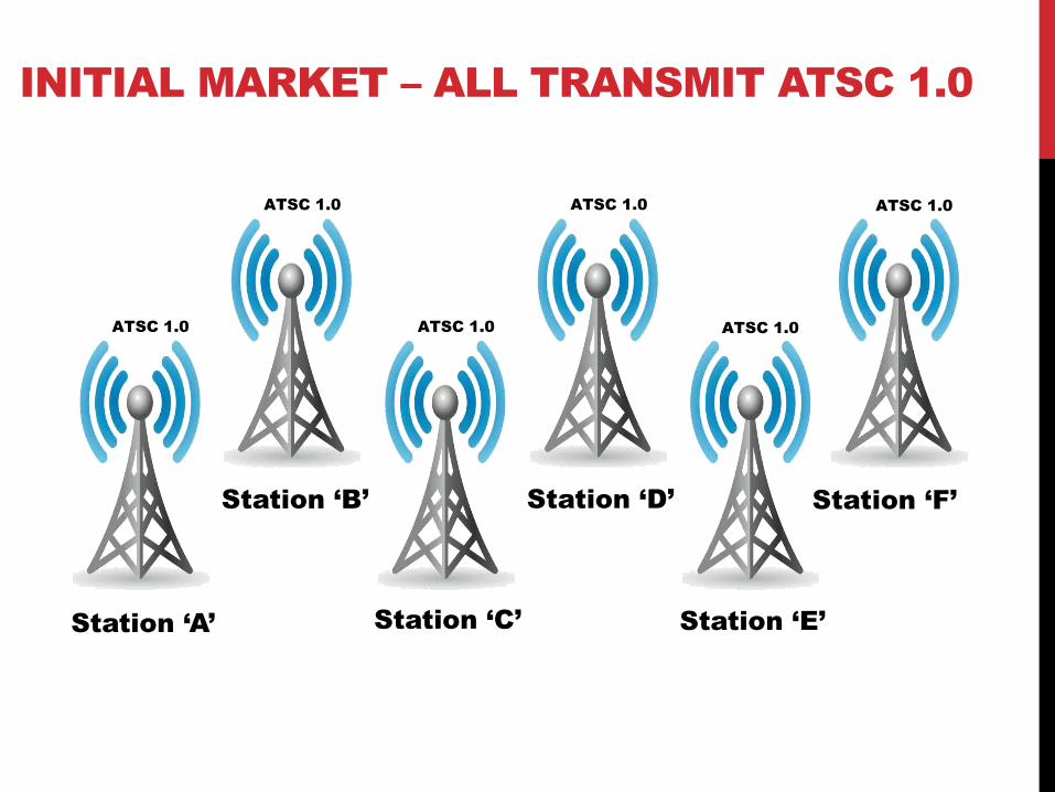
INITIAL MARKET – ALL TRANSMIT ATSC 1.0
Station ‘A’
Station ‘B’
Station ‘C’
Station ‘D’
Station ‘E’
Station ‘F’
ATSC 1.0
ATSC 1.0 ATSC 1.0
ATSC 1.0 ATSC 1.0
ATSC 1.0

TRANSITION MARKET – SHARED 1.0 AND 3.0
Shared ‘A&E&F’
Programming
Station ‘B’
Station ‘C’
Station ‘D’
Station ‘A&E’
Station ‘A&F’
ATSC 1.0
ATSC 1.0 ATSC 1.0
ATSC 1.0 ATSC 3.0
ATSC 3.0
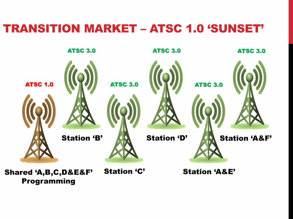
TRANSITION MARKET – ATSC 1.0 ‘SUNSET’
Shared ‘A,B,C,D&E&F’
Programming
Station ‘B’
Station ‘C’
Station ‘D’
Station ‘A&E’
Station ‘A&F’
ATSC 1.0
ATSC 3.0 ATSC 3.0
ATSC 3.0 ATSC 3.0
ATSC 3.0

END TRANSITION – ALL ATSC 3.0
Station ‘B’
Station ‘C’
Station ‘D’
Station ‘E’
Station ‘F’
ATSC 3.0
ATSC 3.0 ATSC 3.0
ATSC 3.0 ATSC 3.0
ATSC 3.0
Station ‘A’
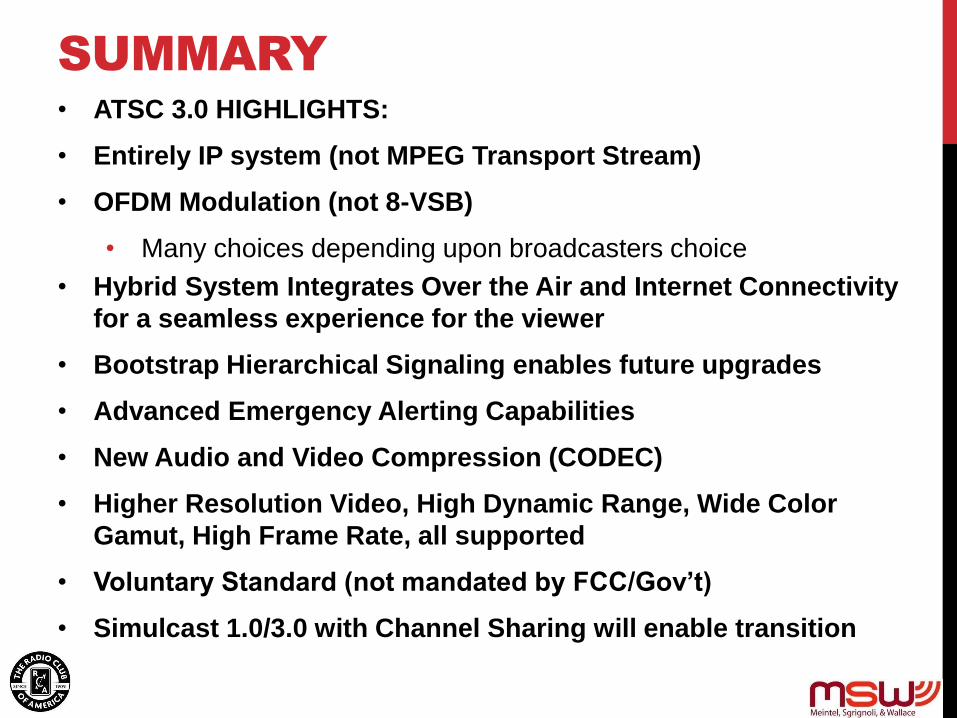
SUMMARY • ATSC 3.0 HIGHLIGHTS:
• Entirely IP system (not MPEG Transport Stream)
• OFDM Modulation (not 8-VSB)
• Many choices depending upon broadcasters choice
• Hybrid System Integrates Over the Air and Internet Connectivity
for a seamless experience for the viewer
• Bootstrap Hierarchical Signaling enables future upgrades
• Advanced Emergency Alerting Capabilities
• New Audio and Video Compression (CODEC)
• Higher Resolution Video, High Dynamic Range, Wide Color
Gamut, High Frame Rate, all supported
• Voluntary Standard (not mandated by FCC/Gov’t)
• Simulcast 1.0/3.0 with Channel Sharing will enable transition

56

CONTACT INFORMATION
Dennis Wallace, C.B.T.E.
Managing Partner
Meintel, Sgrignoli, & Wallace, LLC
1282 Smallwood Drive
Suite 372
Waldorf, Maryland 20603
(202) 251-7589
Email: [email protected]
Web Site: www.mswdtv.com