the naval beach group nttp 3-02.14 rev_a-cdr-5161
TRANSCRIPT

NTTP 3-02.14 (Rev. A)
NAVY TACTICS, TECHNIQUES, ANDPROCEDURES
THE NAVAL BEACH GROUP
NTTP 3-02.14 (Rev. A)
DEPARTMENT OF THE NAVYOFFICE OF THE CHIEF OF NAVAL OPERATIONS
THE UNCLASSIFIED PORTIONS OF THIS PUBLICATION ARE REQUIRED FOR OFFICIAL USE OR FOR ADMINISTRATIVE OR OPERATIONAL PURPOSES ONLY. DISTRIBUTION IS AUTHORIZED TO U.S. GOVERNMENT AGENCIES ONLY. OTHER REQUESTS FOR THE DOCUMENT MUST BE HANDLED IN ACCORDANCE WITH SECNAVINST 5510.31 SERIES.
DERIVED FROM: MULTIPLE SOURCES PRIMARY REVIEW AUTHORITY: SURFACE DECLASSIFY ON: X3 WARFARE DEVELOPMENT GROUP
1 (Reverse Blank) ORIGINAL 0411LP1010522

DEPARTMENT OF THE NAVY COMMANDER SURFACE WARFARE DEVELOPMENT GROUP
2200 AMPHIBIOUS DRIVE NORFOLK. VIRGINIA 23521-2896
September 2001
1. NTTP 3-02.14 (Rev. A), The Naval Beach Group is UNCLASSIFIED. Safeguard in accordance with the Department of the Navy Information Security Program Regulation (SECNAVINST 55 10.36).
2. NTTP 3-02.14 (Rev. A) is effective upon receipt and supersedes/cancels NWP 3-02.14. Destroy superseded/cancelled material in accordance with SECNAVINST 55 10.36.
3. NTTP 3-02.14 (Rev. A) provides information on the organization and employment of the beach group. It shows command relationships and responsibilities of the beach group, shore party, amphibious task force, and landing force. The publication notice (page 5) details major changes to NTTP 3-02.14 (Rev. A).
4. SECNAVINST 5510.31 provides procedures for disclosing this publication or portions thereof to foreign governments or international organizations.
R. R. PETERMAN
1. NTTP 3-02.14 (Rev. A) was reviewed for format and approved Joint and Navy Service Terminology. The contents of NTTP 3-02.14 (Rev. A) support Navy Strategic and Operational Level doctrine.
Navy Warfare~evelo~ment Command

NTTP 3-02.14 (Rev. A)
September 2001
ROUTINGPUBLICATION NOTICE
1. NTTP 3-02.14 (Rev. A), Naval Beach Group, is available in the Navy
Warfare Library. It is effective upon receipt.
2. Summary. Major changes to this publication include:
a. Deleted the Engineer Amphibious Brigade, LST, LCM 6, and refer
ences to LCM in conjunction with amphibious assault
b. Added Marine Corps Transportation Support Battalion
c. Updated assault craft unit (air cushion) to assault craft unit
(nondisplacement), amphibious construction battalion capabilities, and
photographic resume of the Naval Beach Group assets; and realigned
Beach Support Unit elements under maritime pre-positioning force or
ganization vice landing force beach party group tactical organization.
_____________________________
Navy Warfare Library Custodian
Navy warfare library publications must be made readily available to all users and other interested personnel within the U.S. Navy.
Note to Navy Warfare Library Custodian:
This notice should be duplicated for routing to cognizant personnel to keep them informed of
changes to this publication.
5 (Reverse Blank) ORIGINAL


NTTP 3-02.14 (Rev. A)
DOCTRINAL STATEMENT
The contents of this publication provide baseline tactics that establish the preferred beginning point for the tactical commander. Options to the baseline tactics are also presented. Tactical commanders will use baseline tactics to build the tactical innovation necessary for success in naval warfighting. Baseline tactics herein will be used as the basic structure for training.
7 (Reverse Blank) ORIGINAL


NTTP 3-02.14 (Rev. A)
The Naval Beach Group
CONTENTS
Page No.
EXECUTIVE SUMMARY
EX.1 INTRODUCTION. . . . . . . . . . . . . . . . . . . . . . . . . . . . . . . . . . . . . . . . . . . . . . . . . . . . . . . . . . EX-1
EX.2 SUPPORTING DOCUMENTATION . . . . . . . . . . . . . . . . . . . . . . . . . . . . . . . . . . . . . . . . . . EX-1
CHAPTER 1 — LANDING FORCE SUPPORT PARTY OPERATIONS
1.1 ORGANIZATION. . . . . . . . . . . . . . . . . . . . . . . . . . . . . . . . . . . . . . . . . . . . . . . . . . . . . . . . . . 1-11.1.1 Naval Beach Group . . . . . . . . . . . . . . . . . . . . . . . . . . . . . . . . . . . . . . . . . . . . . . . . . . . . . . . . . 1-11.1.2 Shore Party Group (Marine) . . . . . . . . . . . . . . . . . . . . . . . . . . . . . . . . . . . . . . . . . . . . . . . . . . 1-11.1.3 Joint Amphibious Operations . . . . . . . . . . . . . . . . . . . . . . . . . . . . . . . . . . . . . . . . . . . . . . . . . 1-2
1.2 MULTIDIVISION OPERATIONS. . . . . . . . . . . . . . . . . . . . . . . . . . . . . . . . . . . . . . . . . . . . . 1-21.2.1 Tactical Organization . . . . . . . . . . . . . . . . . . . . . . . . . . . . . . . . . . . . . . . . . . . . . . . . . . . . . . . 1-21.2.2 Command Relationships . . . . . . . . . . . . . . . . . . . . . . . . . . . . . . . . . . . . . . . . . . . . . . . . . . . . . 1-31.2.3 Planning. . . . . . . . . . . . . . . . . . . . . . . . . . . . . . . . . . . . . . . . . . . . . . . . . . . . . . . . . . . . . . . . . . 1-31.2.4 Detailed Training and Operations . . . . . . . . . . . . . . . . . . . . . . . . . . . . . . . . . . . . . . . . . . . . . . 1-3
CHAPTER 2 — NAVAL BEACH GROUP
2.1 DESCRIPTION . . . . . . . . . . . . . . . . . . . . . . . . . . . . . . . . . . . . . . . . . . . . . . . . . . . . . . . . . . . . 2-1
2.2 MISSION. . . . . . . . . . . . . . . . . . . . . . . . . . . . . . . . . . . . . . . . . . . . . . . . . . . . . . . . . . . . . . . . . 2-12.2.1 Tasks . . . . . . . . . . . . . . . . . . . . . . . . . . . . . . . . . . . . . . . . . . . . . . . . . . . . . . . . . . . . . . . . . . . . 2-22.2.2 Planning, Liaison, and Staff Duties . . . . . . . . . . . . . . . . . . . . . . . . . . . . . . . . . . . . . . . . . . . . . 2-22.2.3 Capabilities . . . . . . . . . . . . . . . . . . . . . . . . . . . . . . . . . . . . . . . . . . . . . . . . . . . . . . . . . . . . . . . 2-32.2.4 Equipment . . . . . . . . . . . . . . . . . . . . . . . . . . . . . . . . . . . . . . . . . . . . . . . . . . . . . . . . . . . . . . . . 2-3
2.3 ORGANIZATION. . . . . . . . . . . . . . . . . . . . . . . . . . . . . . . . . . . . . . . . . . . . . . . . . . . . . . . . . . 2-32.3.1 Landing Force Beach Party Headquarters . . . . . . . . . . . . . . . . . . . . . . . . . . . . . . . . . . . . . . . . 2-4
2.4 COMMAND RELATIONSHIPS . . . . . . . . . . . . . . . . . . . . . . . . . . . . . . . . . . . . . . . . . . . . . . 2-4
2.5 PLANNING. . . . . . . . . . . . . . . . . . . . . . . . . . . . . . . . . . . . . . . . . . . . . . . . . . . . . . . . . . . . . . . 2-42.5.1 Causeway Ferry and Assault Craft Elements . . . . . . . . . . . . . . . . . . . . . . . . . . . . . . . . . . . . . 2-42.5.2 Considerations . . . . . . . . . . . . . . . . . . . . . . . . . . . . . . . . . . . . . . . . . . . . . . . . . . . . . . . . . . . . . 2-42.5.3 Beach Party Operations . . . . . . . . . . . . . . . . . . . . . . . . . . . . . . . . . . . . . . . . . . . . . . . . . . . . . . 2-72.5.4 Training . . . . . . . . . . . . . . . . . . . . . . . . . . . . . . . . . . . . . . . . . . . . . . . . . . . . . . . . . . . . . . . . . . 2-8
9 ORIGINAL

NTTP 3-02.14 (Rev. A)
Page No
2.6 OPERATIONS . . . . . . . . . . . . . . . . . . . . . . . . . . . . . . . . . . . . . . . . . . . . . . . . . . . . . . . . . . . . 2-82.6.1 Embarkation . . . . . . . . . . . . . . . . . . . . . . . . . . . . . . . . . . . . . . . . . . . . . . . . . . . . . . . . . . . . . . 2-82.6.2 Rehearsals . . . . . . . . . . . . . . . . . . . . . . . . . . . . . . . . . . . . . . . . . . . . . . . . . . . . . . . . . . . . . . . . 2-82.6.3 Ship To Shore Movement . . . . . . . . . . . . . . . . . . . . . . . . . . . . . . . . . . . . . . . . . . . . . . . . . . . . 2-8
2.7 COMMUNICATIONS . . . . . . . . . . . . . . . . . . . . . . . . . . . . . . . . . . . . . . . . . . . . . . . . . . . . . . 2-82.7.1 Capabilities . . . . . . . . . . . . . . . . . . . . . . . . . . . . . . . . . . . . . . . . . . . . . . . . . . . . . . . . . . . . . . . 2-82.7.2 Planning. . . . . . . . . . . . . . . . . . . . . . . . . . . . . . . . . . . . . . . . . . . . . . . . . . . . . . . . . . . . . . . . . . 2-92.7.3 Establishment . . . . . . . . . . . . . . . . . . . . . . . . . . . . . . . . . . . . . . . . . . . . . . . . . . . . . . . . . . . . . 2-9
2.8 MEDICAL SERVICE . . . . . . . . . . . . . . . . . . . . . . . . . . . . . . . . . . . . . . . . . . . . . . . . . . . . . . . 2-9
2.9 LOGISTICS. . . . . . . . . . . . . . . . . . . . . . . . . . . . . . . . . . . . . . . . . . . . . . . . . . . . . . . . . . . . . . . 2-92.9.1 Support Afloat . . . . . . . . . . . . . . . . . . . . . . . . . . . . . . . . . . . . . . . . . . . . . . . . . . . . . . . . . . . . . 2-92.9.2 Support Ashore . . . . . . . . . . . . . . . . . . . . . . . . . . . . . . . . . . . . . . . . . . . . . . . . . . . . . . . . . . . . 2-9
CHAPTER 3 — BEACHMASTER UNIT
3.1 DESCRIPTION . . . . . . . . . . . . . . . . . . . . . . . . . . . . . . . . . . . . . . . . . . . . . . . . . . . . . . . . . . . . 3-1
3.2 MISSION. . . . . . . . . . . . . . . . . . . . . . . . . . . . . . . . . . . . . . . . . . . . . . . . . . . . . . . . . . . . . . . . . 3-13.2.1 Tasks . . . . . . . . . . . . . . . . . . . . . . . . . . . . . . . . . . . . . . . . . . . . . . . . . . . . . . . . . . . . . . . . . . . . 3-13.2.2 Capabilities . . . . . . . . . . . . . . . . . . . . . . . . . . . . . . . . . . . . . . . . . . . . . . . . . . . . . . . . . . . . . . . 3-23.2.3 Equipment . . . . . . . . . . . . . . . . . . . . . . . . . . . . . . . . . . . . . . . . . . . . . . . . . . . . . . . . . . . . . . . . 3-2
3.3 ORGANIZATION. . . . . . . . . . . . . . . . . . . . . . . . . . . . . . . . . . . . . . . . . . . . . . . . . . . . . . . . . . 3-23.3.1 Beach Party Group Headquarters . . . . . . . . . . . . . . . . . . . . . . . . . . . . . . . . . . . . . . . . . . . . . . 3-23.3.2 Beach Party Team . . . . . . . . . . . . . . . . . . . . . . . . . . . . . . . . . . . . . . . . . . . . . . . . . . . . . . . . . . 3-23.3.3 Craft Landing Zone Control Team . . . . . . . . . . . . . . . . . . . . . . . . . . . . . . . . . . . . . . . . . . . . . 3-3
3.4 COMMAND RELATIONSHIPS . . . . . . . . . . . . . . . . . . . . . . . . . . . . . . . . . . . . . . . . . . . . . . 3-43.4.1 Amphibious Operations. . . . . . . . . . . . . . . . . . . . . . . . . . . . . . . . . . . . . . . . . . . . . . . . . . . . . . 3-43.4.2 Maritime Pre-positioning Force Operations . . . . . . . . . . . . . . . . . . . . . . . . . . . . . . . . . . . . . . 3-4
3.5 PLANNING . . . . . . . . . . . . . . . . . . . . . . . . . . . . . . . . . . . . . . . . . . . . . . . . . . . . . . . . . . . . . . 3-43.5.1 Amphibious Operations. . . . . . . . . . . . . . . . . . . . . . . . . . . . . . . . . . . . . . . . . . . . . . . . . . . . . . 3-43.5.2 Maritime Pre-positioning Force Operations . . . . . . . . . . . . . . . . . . . . . . . . . . . . . . . . . . . . . . 3-4
3.6 BEACH PARTY OPERATIONS . . . . . . . . . . . . . . . . . . . . . . . . . . . . . . . . . . . . . . . . . . . . . . 3-53.6.1 Embarkation. . . . . . . . . . . . . . . . . . . . . . . . . . . . . . . . . . . . . . . . . . . . . . . . . . . . . . . . . . . . . . . 3-53.6.2 Ship To Shore Movement.. . . . . . . . . . . . . . . . . . . . . . . . . . . . . . . . . . . . . . . . . . . . . . . . . . . . 3-53.6.3 Command Post. . . . . . . . . . . . . . . . . . . . . . . . . . . . . . . . . . . . . . . . . . . . . . . . . . . . . . . . . . . . . 3-53.6.4 Maritime Pre-positioning Force Operations . . . . . . . . . . . . . . . . . . . . . . . . . . . . . . . . . . . . . . 3-5
3.7 COMMUNICATIONS . . . . . . . . . . . . . . . . . . . . . . . . . . . . . . . . . . . . . . . . . . . . . . . . . . . . . . 3-53.7.1 Planning. . . . . . . . . . . . . . . . . . . . . . . . . . . . . . . . . . . . . . . . . . . . . . . . . . . . . . . . . . . . . . . . . . 3-53.7.2 Establishment . . . . . . . . . . . . . . . . . . . . . . . . . . . . . . . . . . . . . . . . . . . . . . . . . . . . . . . . . . . . . 3-53.7.3 Landing Force Beach Party Headquarters . . . . . . . . . . . . . . . . . . . . . . . . . . . . . . . . . . . . . . . . 3-6
10 ORIGINAL

NTTP 3-02.14 (Rev. A)
Page No.
3.7.4 Message Center and Telephone Service . . . . . . . . . . . . . . . . . . . . . . . . . . . . . . . . . . . . . . . . . 3-6
3.8 MEDICAL SERVICE . . . . . . . . . . . . . . . . . . . . . . . . . . . . . . . . . . . . . . . . . . . . . . . . . . . . . . . 3-6
3.9 LOGISTICS. . . . . . . . . . . . . . . . . . . . . . . . . . . . . . . . . . . . . . . . . . . . . . . . . . . . . . . . . . . . . . . 3-6
CHAPTER 4 — AMPHIBIOUS CONSTRUCTION BATTALION
4.1 DESCRIPTION . . . . . . . . . . . . . . . . . . . . . . . . . . . . . . . . . . . . . . . . . . . . . . . . . . . . . . . . . . . . 4-1
4.2 MISSION. . . . . . . . . . . . . . . . . . . . . . . . . . . . . . . . . . . . . . . . . . . . . . . . . . . . . . . . . . . . . . . . . 4-14.2.1 Tasks . . . . . . . . . . . . . . . . . . . . . . . . . . . . . . . . . . . . . . . . . . . . . . . . . . . . . . . . . . . . . . . . . . . . 4-14.2.2 Capabilities . . . . . . . . . . . . . . . . . . . . . . . . . . . . . . . . . . . . . . . . . . . . . . . . . . . . . . . . . . . . . . . 4-1
4.3 ORGANIZATION. . . . . . . . . . . . . . . . . . . . . . . . . . . . . . . . . . . . . . . . . . . . . . . . . . . . . . . . . . 4-2
4.4 COMMAND RELATIONSHIPS . . . . . . . . . . . . . . . . . . . . . . . . . . . . . . . . . . . . . . . . . . . . . . 4-24.4.1 Operational Control . . . . . . . . . . . . . . . . . . . . . . . . . . . . . . . . . . . . . . . . . . . . . . . . . . . . . . . . . 4-2
4.5 PLANNING. . . . . . . . . . . . . . . . . . . . . . . . . . . . . . . . . . . . . . . . . . . . . . . . . . . . . . . . . . . . . . . 4-3
4.6 OPERATIONS . . . . . . . . . . . . . . . . . . . . . . . . . . . . . . . . . . . . . . . . . . . . . . . . . . . . . . . . . . . . 4-34.6.1 Embarkation . . . . . . . . . . . . . . . . . . . . . . . . . . . . . . . . . . . . . . . . . . . . . . . . . . . . . . . . . . . . . . 4-34.6.2 Causeway Pier . . . . . . . . . . . . . . . . . . . . . . . . . . . . . . . . . . . . . . . . . . . . . . . . . . . . . . . . . . . . . 4-34.6.3 Causeway Ferry . . . . . . . . . . . . . . . . . . . . . . . . . . . . . . . . . . . . . . . . . . . . . . . . . . . . . . . . . . . . 4-44.6.4 Elevated Causeway System (Modular) . . . . . . . . . . . . . . . . . . . . . . . . . . . . . . . . . . . . . . . . . . 4-44.6.5 Side-Loadable Warping Tug and Tender Boat . . . . . . . . . . . . . . . . . . . . . . . . . . . . . . . . . . . . 4-54.6.6 Ship To Shore Bulk Fuel . . . . . . . . . . . . . . . . . . . . . . . . . . . . . . . . . . . . . . . . . . . . . . . . . . . . . 4-54.6.7 Camp Support Element/Limited Construction and Beach Improvements . . . . . . . . . . . . . . . 4-54.6.8 Beach Salvage . . . . . . . . . . . . . . . . . . . . . . . . . . . . . . . . . . . . . . . . . . . . . . . . . . . . . . . . . . . . . 4-6
4.7 COMMUNICATIONS . . . . . . . . . . . . . . . . . . . . . . . . . . . . . . . . . . . . . . . . . . . . . . . . . . . . . . 4-6
4.8 MEDICAL SERVICE . . . . . . . . . . . . . . . . . . . . . . . . . . . . . . . . . . . . . . . . . . . . . . . . . . . . . . . 4-6
4.9 LOGISTICS. . . . . . . . . . . . . . . . . . . . . . . . . . . . . . . . . . . . . . . . . . . . . . . . . . . . . . . . . . . . . . . 4-6
CHAPTER 5 — ASSAULT CRAFT UNIT (DISPLACEMENT)
5.1 DESCRIPTION . . . . . . . . . . . . . . . . . . . . . . . . . . . . . . . . . . . . . . . . . . . . . . . . . . . . . . . . . . . . 5-1
5.2 MISSION. . . . . . . . . . . . . . . . . . . . . . . . . . . . . . . . . . . . . . . . . . . . . . . . . . . . . . . . . . . . . . . . . 5-15.2.1 Tasks . . . . . . . . . . . . . . . . . . . . . . . . . . . . . . . . . . . . . . . . . . . . . . . . . . . . . . . . . . . . . . . . . . . . 5-15.2.2 Capabilities . . . . . . . . . . . . . . . . . . . . . . . . . . . . . . . . . . . . . . . . . . . . . . . . . . . . . . . . . . . . . . . 5-1
5.3 ORGANIZATION. . . . . . . . . . . . . . . . . . . . . . . . . . . . . . . . . . . . . . . . . . . . . . . . . . . . . . . . . . 5-1
5.4 COMMAND RELATIONSHIPS . . . . . . . . . . . . . . . . . . . . . . . . . . . . . . . . . . . . . . . . . . . . . . 5-2
11 ORIGINAL

NTTP 3-02.14 (Rev. A)
Page No.
5.4.1 Amphibious Operations . . . . . . . . . . . . . . . . . . . . . . . . . . . . . . . . . . . . . . . . . . . . . . . . . . . 5-25.4.2 Maritime Pre-positioning Force Operations. . . . . . . . . . . . . . . . . . . . . . . . . . . . . . . . . . . . 5-2
5.5 PLANNING . . . . . . . . . . . . . . . . . . . . . . . . . . . . . . . . . . . . . . . . . . . . . . . . . . . . . . . . . . . . 5-25.5.1 Organization . . . . . . . . . . . . . . . . . . . . . . . . . . . . . . . . . . . . . . . . . . . . . . . . . . . . . . . . . . . . 5-25.5.2 Logistics . . . . . . . . . . . . . . . . . . . . . . . . . . . . . . . . . . . . . . . . . . . . . . . . . . . . . . . . . . . . . . . 5-2
5.6 OPERATIONS. . . . . . . . . . . . . . . . . . . . . . . . . . . . . . . . . . . . . . . . . . . . . . . . . . . . . . . . . . 5-2
5.7 COMMUNICATIONS. . . . . . . . . . . . . . . . . . . . . . . . . . . . . . . . . . . . . . . . . . . . . . . . . . . . 5-3
5.8 MEDICAL SERVICE . . . . . . . . . . . . . . . . . . . . . . . . . . . . . . . . . . . . . . . . . . . . . . . . . . . . 5-3
5.9 LOGISTICS . . . . . . . . . . . . . . . . . . . . . . . . . . . . . . . . . . . . . . . . . . . . . . . . . . . . . . . . . . . . 5-35.9.1 Afloat Repair Team . . . . . . . . . . . . . . . . . . . . . . . . . . . . . . . . . . . . . . . . . . . . . . . . . . . . . . 5-3
CHAPTER 6 — ASSAULT CRAFT UNIT (NONDISPLACEMENT)
6.1 DESCRIPTION . . . . . . . . . . . . . . . . . . . . . . . . . . . . . . . . . . . . . . . . . . . . . . . . . . . . . . . . . 6-1
6.2 MISSION . . . . . . . . . . . . . . . . . . . . . . . . . . . . . . . . . . . . . . . . . . . . . . . . . . . . . . . . . . . . . . 6-16.2.1 Tasks. . . . . . . . . . . . . . . . . . . . . . . . . . . . . . . . . . . . . . . . . . . . . . . . . . . . . . . . . . . . . . . . . . 6-16.2.2 Capabilities. . . . . . . . . . . . . . . . . . . . . . . . . . . . . . . . . . . . . . . . . . . . . . . . . . . . . . . . . . . . . 6-1
6.3 ORGANIZATION . . . . . . . . . . . . . . . . . . . . . . . . . . . . . . . . . . . . . . . . . . . . . . . . . . . . . . . 6-1
6.4 COMMAND RELATIONSHIPS. . . . . . . . . . . . . . . . . . . . . . . . . . . . . . . . . . . . . . . . . . . . 6-1
6.5 PLANNING . . . . . . . . . . . . . . . . . . . . . . . . . . . . . . . . . . . . . . . . . . . . . . . . . . . . . . . . . . . . 6-26.5.1 Organization . . . . . . . . . . . . . . . . . . . . . . . . . . . . . . . . . . . . . . . . . . . . . . . . . . . . . . . . . . . . 6-26.5.2 Logistics . . . . . . . . . . . . . . . . . . . . . . . . . . . . . . . . . . . . . . . . . . . . . . . . . . . . . . . . . . . . . . . 6-2
6.6 OPERATIONS. . . . . . . . . . . . . . . . . . . . . . . . . . . . . . . . . . . . . . . . . . . . . . . . . . . . . . . . . . 6-2
6.7 COMMUNICATIONS. . . . . . . . . . . . . . . . . . . . . . . . . . . . . . . . . . . . . . . . . . . . . . . . . . . . 6-2
6.8 MEDICAL SERVICE . . . . . . . . . . . . . . . . . . . . . . . . . . . . . . . . . . . . . . . . . . . . . . . . . . . . 6-2
6.9 LOGISTICS . . . . . . . . . . . . . . . . . . . . . . . . . . . . . . . . . . . . . . . . . . . . . . . . . . . . . . . . . . . . 6-26.9.1 Maintenance Detachments . . . . . . . . . . . . . . . . . . . . . . . . . . . . . . . . . . . . . . . . . . . . . . . . . 6-2
APPENDIX A — PHOTOGRAPHIC RESUME OF NAVAL BEACH GROUP ASSETS
INDEX . . . . . . . . . . . . . . . . . . . . . . . . . . . . . . . . . . . . . . . . . . . . . . . . . . . . . . . . . . . . . . . . . . . . . . Index-1
12 ORIGINAL

NTTP 3-02.14 (Rev. A)
LIST OF ILLUSTRATIONS
Page No.
CHAPTER 1 - LANDING FORCE SUPPORT PARTY OPERATIONS
Figure 1-1. Marine Corps Transportation Support Battalion . . . . . . . . . . . . . . . . . . . . 1-2Figure 1-2. Landing Force Beach Party Group Tactical Organization . . . . . . . . . . . . . . . 1-3Figure 1-3. Landing Force Support Party Headquarters Organization on the Beach . . . . . . . . 1-4
CHAPTER 2 - NAVAL BEACH GROUP
Figure 2-1. Naval Beach Group Administrative Organization . . . . . . . . . . . . . . . . . . . 2-2Figure 2-2. Maritime Pre-positioning Force Organization (Arrival and Assembly) . . . . . . . . 2-5Figure 2-3. Assault Command Relationships . . . . . . . . . . . . . . . . . . . . . . . . . . . . 2-6Figure 2-4. Control Ship Coordination Net . . . . . . . . . . . . . . . . . . . . . . . . . . . . . 2-10Figure 2-5. Landing Force Beach Party Coordination Net . . . . . . . . . . . . . . . . . . . . . 2-10
CHAPTER 3 - BEACHMASTER UNIT
Figure 3-1. Beach Boat Control Net (Boat A). . . . . . . . . . . . . . . . . . . . . . . . . . . . 3-7Figure 3-2. Beach Operations Net . . . . . . . . . . . . . . . . . . . . . . . . . . . . . . . . . . 3-7Figure 3-3. Beach Administrative Net. . . . . . . . . . . . . . . . . . . . . . . . . . . . . . . . 3-8Figure 3-4. Beachmasters Coordination Net . . . . . . . . . . . . . . . . . . . . . . . . . . . . 3-8
CHAPTER 4 - AMPHIBIOUS CONSTRUCTION BATTALION
Figure 4-1. Shore Delivery Rates of Bulk Fuel . . . . . . . . . . . . . . . . . . . . . . . . . . . 4-6
APPENDIX A - PHOTOGRAPHIC RESUME OF NAVAL BEACH GROUP ASSETS
Figure A-1. Causeway Pier . . . . . . . . . . . . . . . . . . . . . . . . . . . . . . . . . . . . . A-1Figure A-2. "P" Series Pontoons . . . . . . . . . . . . . . . . . . . . . . . . . . . . . . . . . . . A-2Figure A-3. Side-Loadable Warping Tug . . . . . . . . . . . . . . . . . . . . . . . . . . . . . . A-3Figure A-4. Waterjet (Side-Loadable Warping Tug) . . . . . . . . . . . . . . . . . . . . . . . . . A-4Figure A-5. Causeway Section, Powered . . . . . . . . . . . . . . . . . . . . . . . . . . . . . . A-5Figure A-6. Causeway Ferry . . . . . . . . . . . . . . . . . . . . . . . . . . . . . . . . . . . . . A-6Figure A-7. Elevated Causeway System (Modular) . . . . . . . . . . . . . . . . . . . . . . . . . A-7Figure A-8. Amphibious Assault Bulk Fuel System Buoyant (Side-Loadable Warping Tug
Mounted) . . . . . . . . . . . . . . . . . . . . . . . . . . . . . . . . . . . . . . . . A-8Figure A-9. LARC-V . . . . . . . . . . . . . . . . . . . . . . . . . . . . . . . . . . . . . . . . A-9Figure A-10. LCPL Mark 13 . . . . . . . . . . . . . . . . . . . . . . . . . . . . . . . . . . . . . A-10Figure A-11. LCM 8. . . . . . . . . . . . . . . . . . . . . . . . . . . . . . . . . . . . . . . . . . A-11Figure A-12. LCU 1600 Class. . . . . . . . . . . . . . . . . . . . . . . . . . . . . . . . . . . . . A-12Figure A-13. LCM Causeway Tender Boat . . . . . . . . . . . . . . . . . . . . . . . . . . . . . . A-13Figure A-14. LCAC . . . . . . . . . . . . . . . . . . . . . . . . . . . . . . . . . . . . . . . . . . A-14
13 (Reverse Blank) ORIGINAL


NTTP 3-02.14 (Rev. A)
RECORD OF CHANGES
Change No. and Date of Change
Date of Entry Page Count Verified By (Signature)
15 ORIGINAL

NTTP 3-02.14 (Rev. A)
RECORD OF CHANGES (continued)
Change No. and Date of Change
Date of Entry Page Count Verified By (Signature)
16 ORIGINAL
NTTP 3-02.14 (Rev. A)
LIST OF ACRONYMS AND ABBREVIATIONS
A
AABFS amphibious assault bulk fuel system
AABWS amphibious assault bulk water system
AAOE arrival assembly operations element
AAOG arrival and assembly operations group
AASP arrival and assembly support party
ACE air combat element
ACO air contact officer
ACU assault craft unit
AE assault echelon
AFOE assault follow-on echelon
ALCE airlift control element
AOA amphibious objective area
AOR area of responsibility
ARG amphibious ready group
ATF amphibious task force
B
BMU beachmaster unit
BOG beach operations group
BPG beach party group
BPT beach party team
C
CATF commander, amphibious task force
CESE civil engineering support equipment
CLF commander, landing force
CLZ craft landing zone
CMPF commander, maritime pre-positioning force
CNO Chief of Naval Operations
CO commanding officer
17 ORIGINAL

NTTP 3-02.14 (Rev. A)
CPP craft penetration point
CSNP causeway section, nonpowered
CSO chief staff officer
CSP causeway section, powered
CSS combat service support
CSSE combat service support element
E
ELCAS elevated causeway system
ELCAS(M) elevated causeway system (modular)
EPW enemy prisoner of war
F
FLTCINC fleet commander in chief
FPO
FSSG
GCE
HF
HQ
HWM
ISO
JLOTS
LARC-V
LCAC
LCM
force protection officer
force service support group (USMC)
G
ground combat element
H
high frequency
headquarters
high water mark
I
International Organization for Standardization
J
joint logistics over-the-shore
L
lighter, amphibious resupply, cargo
landing craft air cushion
landing craft, mechanized
18 ORIGINAL
NTTP 3-02.14 (Rev. A)
LCPL
LCS
LCU
LF
LFBP
LFSP
LO/LO
LSV
LZ
MAGTF
MCWP
MEB
MEF
MEU
MLW
MPF
MPSRON
NAVCHAPGRU
NBG
NL
NSE
NTTP
NWP
OCO
OCU
OIC
OPCON
OPDS
OUB
landing craft personnel (large)
LCAC control ship
landing craft, utility
landing force
landing force beach party
landing force support party
lift-on/lift-off
logistics support vehicle
landing zone
M
Marine air-ground task force
Marine Corps warfighting publication
Marine expeditionary brigade
Marine expeditionary force
Marine expeditionary unit
mean low water
maritime pre-positioning force
maritime prepositioning ships squadron
N
Navy Cargo Handling and Port Group
naval beach group
Navy lighterage
Navy support element
Navy tactics, techniques, and procedures
Navy warfare publication
O
offload control officer
offload control unit
officer in charge
operational control
offshore petroleum discharge system
OPDS utility boat
19 ORIGINAL

NTTP 3-02.14 (Rev. A)
P
PCO primary control officer
PHIBCB amphibious construction battalion
POG port operations group
R
RE rear echelon
RO/RO roll-on/roll-off
RRDF roll-on/roll-off discharge facility
SEAL sea-air-land team
SEAOPS safe engineering & operations
SELRES selected reserve
SLWT side-loadable warping tug
SHIPALT ship alteration
STS ship to shore
UHF ultra high frequency
VHF very high frequency
S
U
V
20 ORIGINAL

NTTP 3-02.14 (Rev. A)
PREFACE
NTTP 3-02.14 (Rev. A), The Naval Beach Group, sets forth the organization and employment of the beach group. It shows command relationships and responsibilities of the beach group, shore party, amphibious task force, and landing force.
When used with Joint Pub 3-02, Joint Doctrine for Amphibious Operations, and current fleet and task force directives, this publication should provide necessary background information on the basic composition, mission, and capabilities of the NBG.
Throughout this publication, references to other publications imply the effective edition.
Report any page shortage by letter to Commander, Navy Warfare Development Command.
ORDERING DATA
Order a new publication or change, as appropriate, through the Navy supply system. Make changes/revisions to the distribution list in accordance with NTTP 1-01.
RECOMMENDED CHANGES
Submit routine changes to this publication at any time using the accompanying format.
All units and stations submit recommendations to:
COMMANDERSURFACE WARFARE DEVELOPMENT GROUP2200 AMPHIBIOUS DRIVENORFOLK VA 23521-2896
In addition, forward two copies of all recommendations to:
COMMANDERNAVY WARFARE DEVELOPMENT COMMAND686 CUSHING ROADNEWPORT RI 02841-1207
URGENT CHANGE RECOMMENDATIONS
When items for changes are considered to be urgent (as defined in NTTP 1-01, and including matters of safety), send this information by message (see accompanying sample message format) to PRA, with information copies to Navy Warfare Development Command, and all other commands concerned, clearly explaining the proposed change. Information addresses should comment as appropriate. See NTTP 1-01.
INFORMATION CUTOFF DATE
Information in this publication is current as of September 2001. Change information received after this date will be reflected in the next change/revision to this publication.
21 ORIGINAL

NTTP 3-02.14 (Rev. A)
CHANGE SYMBOLS
Revised text in changes is indicated by a black vertical line (change symbol) in either margin of the page, like the one printed next to this paragraph. The change symbol shows where there has been a change. The change might be material added or information restated. A change symbol in the margin, by the chapter number and title, indicates a new or completely revised chapter.
WARNINGS, CAUTIONS, AND NOTES
The following definitions apply to warnings, cautions, and notes found throughout this publication:
WARNING
An operating procedure, practice, or condition that may result in injury or death if not carefully observed or followed.
An operating procedure, practice, or condition that may result in damage to equipment if not carefully observed or followed.
Note
An operating procedure, practice, or condition that is essential to emphasize.
WORDING
The concept of word usage and intended meaning adhered to in this publication is:
“Shall” is used only when application of a procedure is mandatory.
“Should” is used only when application of a procedure is recommended.
“May” and “need not” are used only when application of a procedure is optional.
“Will” is used only to indicate futurity, never to indicate any degree of requirement for application of a procedure.
22 ORIGINAL

NTTP 3-02.14 (Rev. A)
RECOMMENDED CHANGE TO: ____________________________________________________ DATE: _____________
(PUBLICATION NUMBERS/REVISION/CHANGE)
LOCATION: _____________ ____________ ____________ ___________ (PAGE) (PARAGRAPH) (LINE) (FIGURE NUMBER)
TYPE OF CHANGE: ADD DELETE MODIFY TEXT FIGURE
EXACT CHANGE RECOMMENDED: USE ADDITIONAL SHEETS IF NEEDED. GIVE VERBATIM TEXT CHANGES. IF FIGURE IS TO BE ADDED,
SUPPLY ROUGH SKETCH OR IDENTIFY SOURCE. IF FIGURE IS TO BE CHANGED, INCLUDE A MARKED-UP COPY OF EXISTING FIGURE.
RATIONALE:
SUBMITTED BY: _____________________________ __________________________ (ORIGINATING COMMAND) (ORIGINATOR SEQUENCE NUMBER)
_____________________________ __________________________ (POINT OF CONTACT) (PHONE - IDENTIFY DSN OR COMMERCIAL)
PRA ACTION: ACCEPTED MODIFIED REJECTED
REMARKS: (USE ADDITIONAL SHEETS IF NEEDED)
_____________________________ __________________________ (PRA POINT OF CONTACT) (PHONE - IDENTIFY DSN OR COMMERCIAL)
CONFERENCE DATE: _______________________ CONFERENCE AGENDA ITEM NO.: __________
(CLASSIFICATION)
(CLASSIFICATION) PAGE ____ OF ____
NTTP 3-02.14 (Rev. A)
23 ORIGINAL

NTTP 3-02.14 (Rev. A)
FM ORIGINATOR
TO COMSURFWARDEVGRU LITTLE CREEK VA//N5//
INFO COMNAVWARDEVCOM NEWPORT RI//N5//
CINCPACFLT PEARL HARBOR HI//JJJ// or CINCLANTFLT NORFOLK VA//JJJ//
CRA COMMAND PLAD//JJJ//
NAVSAFECEN NORFOLK VA//JJJ//
COMSURFWARDEVGRU DET WEST CORONADO CA//N8//
(Others as appropriate)
BT
CLASSIFICATION//N03510//
MSGID/GENADMIN/(As required)//
SUBJ/URGENT CHANGE RECOMMENDATION FOR NTTP 3-02.14 (Rev. A)//
REF/A/DOC/NWDC
AMPN/REF A IS NTTP 1-01, THE NAVY WARFARE LIBRARY//
POC//(As required)//
RMKS/1. IAW REF A URGENT (SAFETY) CHANGE IS RECOMMENDED FOR NTTP 3-02.14
(Rev. A).
2. PAGE ______ PAR NO ______ LINE NO ______ FIG NO______
3. PROPOSED NEW TEXT (include classification)
4. JUSTIFICATION
24 ORIGINAL

NTTP 3-02.14 (Rev. A)
Executive Summary
EX.1 INTRODUCTION
This Navy tactics, techniques, and procedures (NTTP) manual defines the organization and employment of the beach group. It shows command relationships and responsibilities of the:
1. Beach group
2. Shore party
3. Amphibious task force (ATF)
4. Landing force (LF).
It also provides necessary background information on the basic composition, mission, and capabilities of the naval beach group (NBG).
EX.2 SUPPORTING DOCUMENTATION
Use of this NTTP requires familiarity with the following:
1. Joint Pub 3-02, Joint Doctrine for Amphibious Operations
2. Navy warfare publication (NWP) 3-02.1/Marine Corps warfighting publication (MCWP) 3-31.5, Ship-to-Shore Movement
3. NWP 6-01, Basic Operational Communications Doctrine.
EX-1 (Reverse Blank) ORIGINAL


NTTP 3-02.14 (Rev. A)
CHAPTER 1
Landing Force Support Party Operations
1.1 ORGANIZATION
The landing force support party (LFSP) is a temporary special category task organization of the ATF containing a shore party support element, a helicopter assault support element, and a Navy beach group element. The mission of the LFSP is to:
1. Facilitate the landing and movement of troops, equipment, and supplies across beaches and into landing zones (LZs), ports, and airfields
2. Assist in evacuating casualties and enemy prisoners of war (EPWs) from beaches and LZs
3. Assist in the beaching, retraction, and salvaging of landing ships and craft.
The LFSP is task organized from elements of the Navy and the LF. Its buildup ashore parallels the tactical buildup, beginning with the landing of advance parties and reconnaissance units. The Army’s counterpart is the engineer amphibious brigade.
1.1.1 Naval Beach Group. This command furnishes the Navy’s element, a landing force beach party (LFBP) of an LFSP, and provides the items below for ATF and LF use as outlined in the following chapters. The NBG is described in chapter 2 and its administrative organization is shown in figure 2-1.
1. Pontoon lighterage
2. Causeways
3. Ship to shore (STS) bulk fuel systems
4. Beach traffic control
5. Limited construction team
6. Landing craft.
1.1.2 Shore Party Group (Marine). The transportation support battalion, force service support group (FSSG), provides the command structure and the nucleus of control, administrative, and operational personnel and equipment required for the support of LF operations during the amphibious assault (surface and helicopter types) and for subsequent operations ashore until relieved. The Marine transportation support battalion organization is shown in figure 1-1. All combat service support (CSS) elements of the Marine air-ground task force (MAGTF) may be task organized into the LFSP. The CSS units normally assigned include all or a part of the FSSG and may also include elements of the division (e.g., military police company, combat engineer battalion, and truck company), and the Marine aircraft wing (e.g., wing engineer and aviation logistics squadrons). In addi-
1-1 ORIGINAL

NTTP 3-02.14 (Rev. A)
HQ and Service
Company
Battalion HQ
Communications Platoon
Company HQ
Transportation Support Battalion
Landing Support
Company
Landing Support Platoon
Landing Supporting Equipment Company
Heavy Equipment
Platoon
Motor Transport Platoon
Beach and Terminal
Operations Company
Company HQ
Longshoreman Platoon
Air Delivery Platoon
Shipping and Receiving Platoon
Figure 1-1. Marine Corps Transportation Support Battalion
tion, combat support elements may be part of the LFSP, if necessary.
1.1.3 Joint Amphibious Operations. Refer to Joint Pub 3-02 and Joint Pub 4-01.6, Joint Tactics, Techniques, and Procedures for Joint Logistics Over-the-Shore (JLOTS).
1.2 MULTIDIVISION OPERATIONS
Principles for the landing of one reinforced division also apply to a multidivision operation in which there are one or more attack groups/landing groups in the ATF.
1.2.1 Tactical Organization. The Marine Corps shore party organization follows the organization used for tactical operations:
1. Assigned NBG commanders report to the commander, amphibious task force (CATF), who normally reassigns one NBG to the support of each assault division.
2. Navy components for each division LFSP may be assigned to the CLF for further assignment to the appro-
1-2 ORIGINAL
NTTP 3-02.14 (Rev. A)
priate shore party commander. (See chapter 3.)
3. The remainder of each NBG is assigned to the corresponding attack group commander.
4. Certain components may be retained under the direct control of the CATF to be otherwise assigned as the situation dictates.
5. The administrative commander of the NBGs assigned to the ATF performs planning functions and assumes staff cognizance over beach party matters corresponding to those enumerated in paragraph 2.2.1.
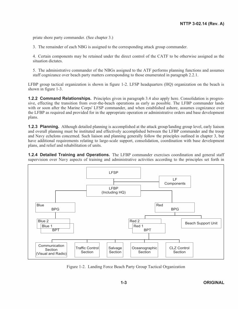
LFBP group tactical organization is shown in figure 1-2. LFSP headquarters (HQ) organization on the beach is shown in figure 1-3.
1.2.2 Command Relationships. Principles given in paragraph 3.4 also apply here. Consolidation is progressive, effecting the transition from over-the-beach operations as early as possible. The LFBP commander lands with or soon after the Marine Corps' LFSP commander, and when established ashore, assumes cognizance over the LFBP as required and provided for in the appropriate operation or administrative orders and base development plans.
1.2.3 Planning. Although detailed planning is accomplished at the attack group/landing group level, early liaison and overall planning must be instituted and effectively accomplished between the LFBP commander and the troop and Navy echelons concerned. Such liaison and planning generally follow the principles outlined in chapter 3, but have additional requirements relating to large-scale support, consolidation, coordination with base development plans, and relief and rehabilitation of units.
1.2.4 Detailed Training and Operations. The LFBP commander exercises coordination and general staff supervision over Navy aspects of training and administrative activities according to the principles set forth in
Red 2
Red 1 BPT
LFSP
LFBP (Including HQ)
LF Components
BPG Blue
BPG Red
Beach Support Unit Blue 2
Blue 1 BPT
Communication Section
(Visual and Radio)
Traffic Control Section
Salvage Section
Oceanographic Section
CLZ Control Section
Figure 1-2. Landing Force Beach Party Group Tactical Organization
1-3 ORIGINAL

NTTP 3-02.14 (Rev. A)
Initial organization on each numbered beach
Shore Party Team Red One
BPT Red One
LF Components
Consolidation of the two BPTs into a BPG for a color beach Shore Party Group
Red
BPG Red HQ
LF Components
BPT Red One BPT Red Two
Consolidation of the two BPTs into the LFBP for a division or MEF landing
LFSP
LFBP Headquarters
LF Components
BPG Red BPG Blue
BPT Red One BPT Red Two BPT Blue One BPT Blue Two
Coordination
OPCON
Figure 1-3. Landing Force Support Party Headquarters Organization on the Beach
chapter 2. During operations, consolidation with the LFBPs is accomplished in consonance with LFSP operations. Coordination between division beach parties should also be effected as soon as possible, and complete consolidation of the LFBP accomplished when feasible.
1-4 ORIGINAL

NTTP 3-02.14 (Rev. A)
CHAPTER 2
Naval Beach Group
2.1 DESCRIPTION
The NBG is a permanently organized Navy command within an amphibious force. It comprises the commander, his staff, a beachmaster unit (BMU), an amphibious construction battalion (PHIBCB), and assault craft units (ACUs). In its tactical configuration, the NBG becomes the LFBP and commander NBG becomes LFBP commander (division beach party and division beach party commander in a U.S. Army LF). Details on the organization and operation of NBG elements are presented in later chapters.
2.2 MISSION
The NBG shall furnish the Navy elements that form the LFBP of the LFSP and shall provide services to the CATF and commander, landing force (CLF) as described below. The CATF and CLF use the services to properly command and control these specifically equipped teams. This enables the teams to move troops, equipment, and supplies across beaches during amphibious assault and to evacuate casualties, refugees, and EPWs as required.
1. Beachmaster traffic control
2. Elements to install and operate a bulk liquid system
3. Landing craft
4. Beach salvage capability
5. Communications.
Additionally, the NBG provides similar services and the following during an assault follow-on echelon (AFOE) and/or maritime pre-positioning force (MPF) operation:
1. Causeway lighterage
2. Causeways (floating)
3. STS bulk fuel/water systems
4. Limited construction capabilities.
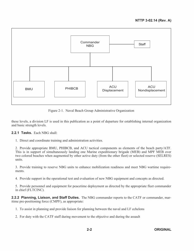
The NBG's administrative organization is shown in figure 2-1.
The strength levels and equipment to be provided will be based on the requirements of the appropriate operational commanders, as designated in current command operation orders and plans. As a planning guide in estimating
2-1 ORIGINAL
NTTP 3-02.14 (Rev. A)
Commander NBG Staff
PHIBCBBMU ACU
Nondisplacement ACU
Displacement
Figure 2-1. Naval Beach Group Administrative Organization
these levels, a division LF is used in this publication as a point of departure for establishing internal organization and basic strength levels.
2.2.1 Tasks. Each NBG shall:
1. Direct and coordinate training and administration activities.
2. Provide appropriate BMU, PHIBCB, and ACU tactical components as elements of the beach party/ATF. This is in support of simultaneously landing one Marine expeditionary brigade (MEB) and MPF MEB over two colored beaches when augmented by other active duty (from the other fleet) or selected reserve (SELRES) units.
3. Provide training to reserve NBG units to enhance mobilization readiness and meet NBG wartime requirements.
4. Provide support in the operational test and evaluation of new NBG equipment and concepts as directed.
5. Provide personnel and equipment for peacetime deployment as directed by the appropriate fleet commander in chief (FLTCINC).
2.2.2 Planning, Liaison, and Staff Duties. The NBG commander reports to the CATF or commander, maritime pre-positioning force (CMPF), as appropriate:
1. To assist in planning and provide liaison for planning between the naval and LF echelons
2. For duty with the CATF staff during movement to the objective and during the assault
2-2 ORIGINAL

NTTP 3-02.14 (Rev. A)
3. For subsequent duty ashore as LFBP commander
4. For duty as Navy support element (NSE) commander for MPF operation
5. For additional duty ashore on the appropriate LF echelon staff, to provide technical information on beach party matters, and for exercise of staff cognizance over beach party activities as required.
Tactical elements are regrouped when they are no longer required by the commander to whom temporarily as-signed and progressively revert to the command of the NBG commander.
2.2.3 Capabilities. Each NBG can support a MEB-sized amphibious operation and one MPF operation simultaneously when augmented by other active duty forces or designated SELRES units. Support of a MEF-sized operation also requires augmentation by other active duty forces and SELRES units. This support includes:
1. The Navy component of an LFSP.
2. Pontoon causeway elements with organic equipment.
3. Beach party teams (BPTs) for lighterage traffic control.
4. Pontoon barge elements capable of providing lighterage operations.
5. Assault craft elements with operating, repair, and HQ personnel. These elements may contain landing craft air cushion (LCAC), landing craft, mechanized ( LCM), landing craft, utility (LCU), or all three.
6. STS bulk fuel elements.
7. Limited construction and camp support elements with organic equipment.
8. Bivouac and communication support to sustain naval beach party activities under field conditions.
9. Construction and operation of an elevated causeway system (ELCAS).
2.2.4 Equipment. Each NBG maintains sufficient equipment and vehicles to support the Navy elements comprising the naval beach party of an LFSP.
2.3 ORGANIZATION
Basic NBG organization (figure 2-1) is designed to perform the administrative functions assigned to that group. The commander's staff is organized under the chief staff officer (CSO) into the following departments:
1. Administrative
2. Operations and plans
3. MPF operations and materials
4. Logistics
5. Readiness and training
2-3 ORIGINAL

NTTP 3-02.14 (Rev. A)
6. Communications.
For assault operations, the NBG assumes its tactical role as elements of the ATF and is organized as shown in figure 1-2. For MPF operations, the NBG is task organized to form the NSE. The NSE consists of an offload control unit (OCU), beach support unit, and defense unit. (See figure 2-2.)
2.3.1 Landing Force Beach Party Headquarters. The HQ, organized as shown in figure 1-3 provides for the control and supervision of the beach party operations by:
1. Maintaining communications with subordinate BPGs and the specified commander afloat
2. Coordinating BPGs to obtain maximum efficiency of the LFBP operations, and assigning special units attached to the LFBP to subordinate groups (and keeping the shore party commander informed)
3. Coordinating the control of boat and amphibious vehicle traffic for efficient employment of boats and vehicles to ensure effective use of landing points, and for evacuation of casualties and EPWs.
2.4 COMMAND RELATIONSHIPS
Upon receipt of the CATF’s directive, the NBG commander activates the required tactical elements by assigning them to the CATF for operational control (OPCON) and further assigning to the CLF or subordinate task force commanders. The NBG commander retains administrative control. During MPF operations, the NBG commander, as NSE commander, controls the Navy Cargo Handling and Port Group (NAVCHAPGRU) element.
The commander of the NBG reports to the CATF for planning and normally is assigned additional duties. In accordance with paragraph 2.2.2, he may be assigned additional duty on the CLF's staff (e.g., in an amphibious assault, he assumes duties as the LFBP commander when established ashore (paragraph 1.2.2)). The LFBP commander then reports to and comes under OPCON of the LFSP commander on those beach operations described in paragraph 2.2. If the NBG commander is assigned additional duty on the CLF’s staff, he lands with the staff. During the latter stages of the general unloading period, he normally initiates a regrouping of his tactical elements (since the OPCON of each is no longer required by the assigned element command) and progressively assumes OPCON of the elements of the NBG. (See figure 2-3.)
2.5 PLANNING
Since the role played by tactical elements of the NBG is essential to the progress of the amphibious operation, plan for their employment concurrently with the tactical and logistical planning for the ATF and LF. The CATF normally assumes planning responsibility for the employment of the assault craft elements of the ACUs and sub-ordinates planning responsibility for the employment of causeway/barge ferry elements of the amphibious construction battalion to the CMPF when assigned in an associated operation. The ATF plans provide for the transfer of OPCON of these tactical elements when they are phased ashore. The CLF is responsible for LFSP plans which govern beach party operations.
2.5.1 Causeway Ferry and Assault Craft Elements. Base planning for operating these elements on the combined requirements of the LF and Navy commands. Establish early liaison for planning between the appropriate elements of the ATF, LF, CMPF (when assigned), and with garrison or advanced base commands designated to relieve these elements. The NBG commander and units providing tactical elements should participate early in the planning cycle and may provide planning liaison between the Navy and LF planning echelons.
2.5.2 Considerations. Factors that influence the organization and planned employment of the tactical elements of the NBG are described below.
2-4 ORIGINAL

NT
TP
3-0
2.1
4 (R
ev. A
)
Ships Master
Lighterage Debark Team
BPG CSSE ACE GCE
AAOE AAOEAAOE
Lighterage Control Teams
Cargo Handling
Nets
USMC Debark Team
AASP
BOG AAOGPOG
ACO
CMPF
MPSRON
NSE
MEB
OCU Defense
Unit
Beach Support
Unit
AAOG
ALCE
FPO
Causeway Platoon
Causeways
Warping Tugs
Platoon Barges
ELCAS
RRDF
Fuels Platoon
Buoyant AABFS
OPDS
Camp Support Platoon
Logistic/Personnel Support
Equipment Maintenance
Limited Construction
Coordination OPCON
Fig
ure 2
-2.
Maritim
e Pre-p
ositio
nin
g F
orce O
rgan
ization (A
rrival an
d A
ssembly
)
2-5
O
RIG
INA
L

NTTP 3-02.14 (Rev. A)
CLF
LFSP
Blue
Shore Party Group Red
Blue
BPG Red
LFBP
Red Two
Shore Party Team
Red One
Red Two
BPT Red One
A
B
A
B
A
B -
Before Shore Party Group/ LFSP and BPG/LFBP land
After they landCooperation and Coordination
Operational Command Authority
Figure 2-3. Assault Command Relationships
2-6 ORIGINAL

NTTP 3-02.14 (Rev. A)
2.5.2.1 Enemy Activity and Installations in the Landing Area. A study of enemy dispositions and defense installations may permit the degree of enemy resistance to be anticipated. Conclusions from the study may indicate a requirement for a particular element of the NBG to be reinforced or to have available additional sup-port.
2.5.2.2 LF Scheme-of-Maneuver. The landing plan normally dictates the structure of the LFSP.
2.5.2.3 Oceanography. A careful study of oceanographic and topographic conditions, with an analysis of the weather effects, indicates the probable employment of the shore party and attached NBG elements and establishes requirements for special equipment. Significant oceanographic conditions are:
1. General character of the surf and littoral currents and the effect on landing ships and craft
2. Beach gradient and composition at various stages of the tide in relation to the suitability for beaching and retracting landing ships and craft
3. Position of the waterline at various stages of the tide with reference to natural and artificial obstacles
4. Breaker type, height, and period
5. Relative wind speed and direction.
2.5.2.4 Beach Capacity. Most often, the single factor limiting the ability to discharge cargo across a beach is the beach capacity. Capacity is variable and depends on:
1. Physical features
2. Weather
3. Oceanographic features
4. Tactical situation
5. Organization and equipping of the beach.
To obtain optimum effectiveness from available forces, reach and maintain a maximum rate of discharge.
Beach capacity depends on the clearance and unloading rates. The clearance rate is the rate at which cargo can be moved from beach unloading points to inland dumps. The unloading rate is the rate at which cargo can be discharged from landing craft, landing ships, and amphibious vehicles. Since the shore party unloads, the estimated unloading rate, as determined by beach capacity calculations, is the measure of the requirements which must be planned for and provided by the beach party.
2.5.3 Beach Party Operations. For planning beach party employment, the CLF normally provides commander’s guidance to the NBG. This includes analysis of the mission, amphibious objective area (AOA), and special considerations. The commander of the NBG provides his estimate of the situation and recommends task organization and support requirements for the LFSP mission. The commander of the NBG integrates CLF’s planning with CATF’s capabilities and plans. Upon receipt of the commander’s decision based on the finalized estimate, the NBG commander formulates the beach party operation.
2-7 ORIGINAL

NTTP 3-02.14 (Rev. A)
Shore party planning should provide for:
1. Logistics requirements for elements of the beach party organization required in this operation
2. Serialization of beach party personnel and organic equipment
3. Combat loading of the beach party with its shore party opposites in assault shipping
4. Coordination and cooperation between shore party and beach party elements in the planning stages.
2.5.4 Training. Effective coordination of beach and shore party operations depends upon integrated preoperational training which may occur during the rehearsals for the operation. To provide for this training, the shore party is normally activated at least 30 days prior to embarkation. The beach party, as directed by the CATF, may also participate. Whenever the final integrated rehearsal does not provide a test of this coordination, perform the test during the preoperational training period. NBG elements retained by the CATF may be required to sup-port shore party training.
2.6 OPERATIONS
2.6.1 Embarkation. The tactical elements of the NBG normally embark in the same transports and landing ships as the LF. Concurrent planning by the ATF and LF provides for this and for the embarkation of organic equipment for landing at the required time and place. The CATF is responsible for providing the CLF with the embarkation requirements for the NBG element.
2.6.2 Rehearsals. The LFBP and officers of the NBG assigned to ATF staffs should participate in prerehearsal command post exercises and all rehearsals. Participation in the final integrated rehearsal normally depends on time available and the reconditioning and loading of equipment. When rehearsal limitations do not permit the participation of these elements, conduct this training in the preoperations period.
2.6.3 Ship to Shore Movement. The tactical elements of the NBG comprising the beach party are employed during the assault and general unloading periods of the STS movement to facilitate:
1. Waterborne movement of troops and materiel by the operation of landing craft and amphibious vehicles
2. Landing and offloading by providing boat traffic control and communications.
Upon completion of initially assigned tasks, NBG tactical elements are normally phased ashore and report to the beach party commander for assignment and designated logistic support. The beach party commander keeps the shore party commander informed of the size and composition of reporting elements while coordinating their anticipated employment. For further discussion, refer to NWP 3-02.1/MCWP 3-31.5.
2.7 COMMUNICATIONS
LFSP communications are designed to furnish the separate functional communication nets required for the logistic support of the LF. This requires establishing separate LF and Navy communications. Navy communications are established in accordance with NWP 6-01 and provided by the beach party. Communications available in tactical elements and provided by the ACU and the PHIBCB are adequate to permit control of their basic functions.
2.7.1 Capabilities. NBG organic communication equipment provides operational communications for the LFBP and personnel-carried and vehicular-mounted communications for group administration and operations. Coverage of the communications organic to each unit is outlined in later chapters.
2-8 ORIGINAL

NTTP 3-02.14 (Rev. A)
2.7.2 Planning. When planning Navy communications, an understanding of employing NBG elements throughout the amphibious operation is required. Make provisions for the transfer of OPCON as elements are phased ashore. Orders for installing, controlling, and operating beach party communications are contained in the CATF's operation orders. This information includes radio frequencies, tactical call signs, and communications security arrangements.
2.7.3 Establishment. The LFBP establishes and maintains radio communications on the following nets:
1. ATF command
2. Control ship coordination
3. Beachmasters lateral coordination.
For further information, refer to figures 2-4 and 2-5 and NWP 6-01.
2.8 MEDICAL SERVICE
Staff and units have medical personnel and equipment to provide first aid and minor medical treatment to organic personnel. However, definitive medical care and hospitalization are furnished by the ship in which embarked while afloat and assigned troop or naval command staff when ashore. Medical personnel assigned to the units and to the staff of the NBG commander assist in planning and provide liaison between their parent unit and the unit providing medical support. The NBG commander reassigns medical personnel and material under his command in accordance with the projected requirements of the amphibious operation.
2.9 LOGISTICS
Sufficient spare parts, special fuels, and administrative consumables are carried for NBG personnel and equipment for the duration specified in the CATF operation order. Tentage, commissary equipment, and personnel required for field living are organic to units of the NBG. The NBG commander and his component commands participate in planning and logistic support of beach group elements.
2.9.1 Support Afloat. Beach group elements are supported by ships in which embarked.
2.9.2 Support Ashore. Fuel, lubricants, rations, water, and ammunition common to both services are provided by the CLF through the appropriate subordinate commander who is directly in charge of the tactical elements of the beach party assigned to the shore party. The extent and nature of the support is determined and specified in the CATF and CLF operation order.
2-9 ORIGINAL

2-10 ORIGINAL
NTTP 3-02.14 (Rev. A)
Figure 2-4. Control Ship Coordination Net
Figure 2-5. Landing Force Beach Party Coordination Net
LFBP Commander
Transport Group Commander
Central Control Ship
Primary Control Ship (Blue Beach)
Primary Control Ship (Red Beach)
LFBP
(Color) BPG HQ
(Color) BPG HQ

NTTP 3-02.14 (Rev. A)
CHAPTER 3
Beachmaster Unit
3.1 DESCRIPTION
The BMU is a commissioned naval unit of the NBG, and is organized administratively and tactically to augment the LFSP HQ and provide appropriate BMU tactical components as elements of the NBG.
3.2 MISSION
The BMU conducts beach party operations to facilitate landing and moving of troops, equipment, and supplies across the beach, and the evacuation of casualties and EPWs in support of the beach party.
3.2.1 Tasks. Each BMU provides appropriate BMU tactical components and can support the simultaneous landing of one assault MEB and one MPF MEB when augmented by other active duty forces (from the other fleet) or designated SELRES units.
The BMU supports the beach party commander by:
1. Communicating with designated naval commanders, naval control units, and within the LFBP.
2. Controlling, with the STS control officer assigned by the CATF, landing ships and craft, and amphibious vehicles in the vicinity of the beach from the surf line to the HWM. If an LCAC craft landing zone (CLZ) is located inland of the high water mark (HWM), the area of responsibility (AOR) assigned to the BMU is extended to include the LCAC transit lane from the craft penetration point (CPP) to the inland side of the CLZ.
3. Coordinating reembarkation of equipment, troops, and supplies with the shore party commander and CATF.
4. Determining and advising suitability for landing amphibious vehicles, craft, ships, and beaching causeways, through coordination with the sea-air-land team (SEAL) teams.
5. Controlling surf zone salvage with assistance from the salvage officer (assigned by the CATF), and accomplishing emergency repairs to landing craft.
6. Advising the LFSP commander of significant naval activities in progress in the vicinity of and on the beaches.
7. Maintaining continuous liaison with naval forces afloat and rendering seaward assistance, as practicable.
8. Providing assistance, as directed by the LFSP commander, in local security and defense of the beach sup-port area.
9. Providing assistance in the evacuation of casualties and EPWs.
3-1 ORIGINAL
NTTP 3-02.14 (Rev. A)
10. Installing, after consultation with the LFSP commander, beaching range markers and lights.
11. Appraising appropriate Navy commanders of wind and surf conditions and any impact the weather might have on current or pending operations.
12. Deploying personnel and limited equipment by air in support of an MPF operation.
3.2.2 Capabilities. Each BMU, when augmented by other active duty forces (from the other fleet) and designated SELRES units, can support the landing of a MEF over two colored beaches.
3.2.3 Equipment. Each BMU maintains sufficient equipment to support six BPTs and two beach party group (BPGs). The naval reserve BPTs are equipped with similar BPT equipment. Active BMUs will maintain assigned civil engineering support equipment (CESE) for the reserves.
3.3 ORGANIZATION
When directed by the NBG commander, the BMU, augmented by detachments from the PHIBCB and the SEAL teams, is tactically organized into a beach party element HQ and BPTs.
3.3.1 Beach Party Group Headquarters. This HQ controls and coordinates the activities of subordinate BPTs and, in addition, maintains liaison with the appropriate transport unit commander.
3.3.2 Beach Party Team. The BPT is the basic unit of the beach party and is the Navy element of the LFSP. There are two BPTs in an LFBP with BPTs under each BPG. (See figure 1-2.) One BPT supports one battalion landing team on a numbered beach. The BPT is organized into the following sections to perform assigned tasks.
3.3.2.1 Communications Section (Radio and Visual)
3.3.2.1.1 Radio. Members carry portable radio equipment ashore in the early stages to enable the beachmaster to establish initial communications on boat control circuits. Vehicular-mounted radio equipment is landed later as directed. The radio section provides the BPT commander with lateral communications within the beach party and with communications to forces afloat.
3.3.2.1.2 Visual. Members maintain visual communications with forces afloat, landing craft, and lateral beaches using semaphore flags, portable signal lights, and 12-inch signal searchlights. To prevent overloading radio circuits, they use visual communications to the greatest extent possible, night and day.
3.3.2.2 Traffic Control Section. To control landing craft by visual means, members are positioned at intervals along the water’s edge, but high enough on the beach to be seen by craftmasters/coxwains. Their primary functions are to:
l. Ensure expedient beaching of craft at safe landing sites.
2. Inform the beachmaster of unusual circumstances that may arise.
3. Supervise the debarkation and reembarkation of troops and equipment.
4. Ensure safety of operations from the first surf line to the HWM.
Personnel are equipped with signal flags and wands for directing landing craft, and with range markers and lights for causeway operations. Refer to NWP 3-02.1/MCWP 3-31.5 for additional information.
3-2 ORIGINAL

NTTP 3-02.14 (Rev. A)
3.3.2.3 Salvage Section. Members consist of personnel from the amphibious construction battalion and the BMU. Equipment available consists of one bulldozer rigged with a fendered blade and a rear winch, and two lighter, amphibious resupply, cargo (LARC-Vs), each equipped with a reinforced pusher bow and a dewatering and firefighting pump. The LARC-V ramp raising capability includes all landing craft up to and including LCM 8 and LCU if LARC-Vs are rigged in tandem. The salvage section, using its vage boat, has the responsibility to:
l. Free broached or swamped boats
2. Haul damaged craft to HWM
3. Raise inoperative ramps
4. Assist the LFSP in:
a. Moving bogged down wheeled vehicles
b. Limited beach improvement
5. Conduct firefighting/dewatering operations for craft and vehicles.
heavy equipment and aided by the sal-
3.3.2.4 Other Sections and Elements. When operational, the pontoon causeway pier, ELCAS, and liquid delivery systems (e.g., amphibious assault bulk fuel system (AABFS)) sections report to the BPG commander. For details on the limited construction section, see paragraph 4.6.7.
3.3.3 Craft Landing Zone Control Team. The CLZ control team's primary mission is to provide the CATF and CLF with command, control, communications, and salvage support to facilitate the over-the-beach landing of troops, equipment, vehicles, and supplies from LCAC. The CLZ control team normally lands on the beach in the first wave after the initial LCAC assault. Immediately upon landing, the team assumes responsibility for:
1. Establishing the command post (LZ control point)
2. Entering prescribed radio nets and establishing effective communications with the LCAC control ship (LCS)
3. Establishing LCAC LZ
4. Providing traffic control for LCAC from CPP to CLZ
5. Maintaining communications with designated naval commanders and control units afloat and between adjacent BPTs
6. Assisting in evacuation of LF casualties and/or EPWs
7. Reporting surf conditions/observations and the general beach situation to appropriate commands, and making other reports, as required.
8. Performing ramp marshal LCAC offload and backload duties.
3-3 ORIGINAL

NTTP 3-02.14 (Rev. A)
3.4 COMMAND RELATIONSHIPS
The command relationships for the BMU are determined by the unit's mission.
3.4.1 Amphibious Operations. Command of the LFSP resides with the CLF. When directed by the CATF, those elements of the NBG that are designated to form the beach party report to the CLF for planning the operation. The CLF directs the LFSP commander (or other subordinate commanders when appropriate) to conduct the planning. OPCON of the beach party elements is passed to the LFSP for the assault, general offloading, and reembarkation phases as the CATF directs.
Navy beach party commanders retain command of the Navy elements ashore at all times. (See figure 2-3.)
3.4.2 Maritime Pre-positioning Force Operations. The BPG reports to the NSE offload control officer (OCO) and is responsible for beach operations including:
1. Advising the NSE OCO of areas available for causeway/boat landing
2. Controlling boat salvage and repair on the beach
3. Maintaining communications with designated naval commanders and units
4. Assisting in evacuation of casualties and EPWs
5. Controlling the beaching and retraction of lighterage.
3.5 PLANNING
3.5.1 Amphibious Operations. The commanding officer (CO) of the BMU assists the beach party commander in developing plans for supporting amphibious operations. LFSP planning provides for:
1. Logistics requirements for elements of the beach party organization required in the operation
2. Serialization of beach party personnel and organic equipment
3. Combat loading of the LFSP, including beach party elements, with their shore party counterparts
4. Coordination and cooperation between LFSP and beach party elements in the planning stages.
3.5.2 Maritime Pre-positioning Force Operations. For MPF operations, the BPG assists the NBG, MPF, and MEB commanders in planning the employment of the beach party element. Since the STS movement is not completed until the offload equipment and supplies have reached the HWM, the BPG acts as the landward end of the movement. As directed by the OCO, the BPG supports the arrival and assembly support party (AASP) and consists of personnel assigned for beach and anchorage reconnaissance, and lifeguard and swimmer security sup-port. The BPG provides:
1. Boat salvage and repair
2. Casualty and EPW evacuation
3. Maintenance of communication with designated naval commanders and units.
3-4 ORIGINAL

NTTP 3-02.14 (Rev. A)
3.6 BEACH PARTY OPERATIONS
3.6.1 Embarkation. The beach party organization embarks in assault shipping per embarkation schedules established by the CATF. Concurrent planning by the ATF and the LF provides for this and for the embarkation of organic equipment so it is landed at the required time and place.
3.6.2 Ship to Shore Movement. The forward echelon of each BPT lands with the forward echelon of the corresponding shore party team. It consists of the beach party commander and elements of the traffic control, salvage, radio, and visual communication sections. The remainder of each BPT is serialized with the corresponding shore party team’s equipment and held in readiness on a designated ship. Each BPT lands with the shore party team normally as part of the first boated wave. The BPG HQ is maintained in readiness with its shore party counterparts and lands when the tactical situation ashore permits.
3.6.3 Command Post. The beach party commander directs the beach operation from the command post. The LFBP commander and each BPG and BPT commander establishes his own command post upon landing. The command posts should:
1. Be located on the beach adjacent to or near the respective shore party team, group, and LFSP command posts
2. Command a good view of the beach area (geographic center, if possible)
3. Be camouflaged to provide protection
4. Include communications (e.g., radio, visual, and field telephone)
5. Include the traffic control center.
The beach party buildup parallels that of the LFSP and is as rapid as the tactical situation permits.
3.6.4 Maritime Pre-positioning Force Operations. During 24-hour MPF operations requiring the offloading of three or more ships, two BPTs and one beach party HQ are normally assigned.
3.7 COMMUNICATIONS
The beach party is primarily responsible for establishing and maintaining effective communications with forces afloat and intercommunication between beach party and LFSP elements.
3.7.1 Planning. Orders for the installation, control, and operation of beach party communications are contained in the operation order. This information includes radio frequencies, tactical call signs, and communications security arrangements.
3.7.2 Establishment. The LFBP establishes and maintains radio communications on the following nets:
1. ATF command
2. Control ship coordination
3. Beachmaster lateral coordination.
3-5 ORIGINAL

NTTP 3-02.14 (Rev. A)
For other than a division-size landing, these nets are covered by the highest echelon of the beach party. For further net information, refer to figures 2-4, 2-5, 3-1 through 3-4, and NWP 6-01.
The normal phasing-in of beach party communications during the assault is described below.
3.7.2.1 Beach Party Team. When the BPT lands, it immediately establishes communications with forces afloat on (color) beach boat control and (color) beach operations circuits. When all sections of the BPT are operational, the (color) beach administrative net and the control ship coordination net circuits will be guarded as soon as possible.
3.7.2.2 Beach Party Group Headquarters. When this HQ has established a command post ashore, the following radio nets are entered:
1. (Color) beach administrative
2. (Color) beach boat control
3. (Color) beach operations
4. Beachmasters coordination.
Upon consolidation of battalion beaches and their BPTs, seaward communications are maintained at the BPG HQ. Initially, all radio communications at this HQ use portable personnel-carried radios, until serials arrive containing vehicular-mounted radios. The beach party commander is net control of the beachmasters coordination circuit.
3.7.3 Landing Force Beach Party Headquarters. Upon consolidation of the colored beaches and their associated BPGs, the LFBP HQ enters and assumes control of the beachmasters lateral coordination net. The LFBP also enters the ATF/attack group command net and the control ship coordination net, thus completing the entire beach party communications link.
3.7.4 Message Center and Telephone Service. Message center facilities established by the LFSP serve the NBG elements attached to the LFSP. The LFSP supplies field phone service, as the situation permits, at all beach party echelons.
3.8 MEDICAL SERVICE
The LFSP controls the flow of casualties from LFSP evacuation stations and LF medical facilities. The beach party commander obtains boats required for medical evacuation and instructs boat coxswains on the destination of casualties. Beach party commanders at all echelons must be thoroughly familiar with the medical annexes of the operation and CATF/CLF administrative orders.
3.9 LOGISTICS
The CO of the BMU provides logistic planning assistance to the NBG commander. (See paragraph 2.9.)
3-6 ORIGINAL

NTTP 3-02.14 (Rev. A)
Transport Unit Commander
Secondary Control Officers
Assistant Boat Group Commanders
(if employed)
Boat Group Commander
(if employed)
Salvage Boat Medical Boat (if employed)
Beach Party Commander
PCO
Figure 3-1. Beach Boat Control Net (Boat A)
Transport Unit Commander
Salvage Boats (if employed)
Boat Group Commander
(if employed)
Individual Transport Ships
Beach Party Commanders
PCO
Figure 3-2. Beach Operations Net
3-7 ORIGINAL

3-8 ORIGINAL
NTTP 3-02.14 (Rev. A)
Figure 3-3. Beach Administrative Net
Figure 3-4. Beachmasters Coordination Net
Transport Unit Commander
Beach Party
Secondary Control Officer
Individual Transport Ship
PCO
(Color) BPG
(Color, Number) BPT
(Color, Number) BPT

NTTP 3-02.14 (Rev. A)
CHAPTER 4
Amphibious Construction Battalion
4.1 DESCRIPTION
The PHIBCB is a commissioned unit of the NBG commanded by an officer of the Civil Engineer Corps.
4.2 MISSION
The primary mission of the PHIBCB is to provide logistics over-the-shore support for amphibious force and MPF operations, including STS transportation of combat cargo, bulk fuel/water, and tactical camp operations. The secondary mission is to assist the LFSP in operations which do not interfere with the primary mission and to undertake logistic construction projects within the capabilities of assigned men and equipment.
4.2.1 Tasks. Each PHIBCB provides appropriate tactical components to the NSE or LFBP as required by the mission. Each PHIBCB, when augmented by the authorized SELRES unit, can support the assault echelon (AE), AFOE, and MPF, while maintaining and operating an rear echelon (RE). MPF operations may occur simultaneously with AE or AFOE operations.
4.2.2 Capabilities. Capabilities include:
1. AE:
a. Install, operate, and maintain one AABFS
b. Provide beach salvage elements to the beachmaster.
2. AFOE:
a. Install, operate, and maintain one offshore petroleum discharge system (OPDS) using side-loadable warping tugs (SLWTs) or OPDS utility boats (OUBs)
b. Deploy, install, and operate one elevated causeway system (modular) (ELCAS(M))
c. Establish and operate up to 1200-person support camp for the NSE
d. Deploy, install, and operate one roll-on/roll-off discharge facility (RRDF)
e. Deploy, assemble, install, operate, and maintain eight barge ferries including one powered by an SLWT.
3. MPF:
a. Deploy personnel and limited equipment using strategic airlift and sealift
4-1 ORIGINAL

NTTP 3-02.14 (Rev. A)
b. Install, operate, and maintain up to five amphibious assault bulk water system (AABWS)
c. Assemble, operate, and maintain a causeway ferry system of 20 causeway section, powered (CSP)/SLWT and associated causeway section, nonpowered (CSNP)
d. Deploy, assemble, install, operate, and maintain one RRDF
e. Establish and operate an 850-person support camp for the NSE.
4. RE:
a. Provide replacement training
b. Provide logistic support for deployed forces
4.3 ORGANIZATION
The many combinations of personnel and equipment that can be employed require a highly flexible organization. Organization of the tactical elements employed in an amphibious assault is governed by the combined requirements of the CATF and CLF.
4.4 COMMAND RELATIONSHIPS
Based on CATF requirements, the commander of the NBG directs the CO of the PHIBCB to activate the required tactical elements and direct them to report to the CATF for OPCON, or for reassignment to subordinate commands, as appropriate. The CO of the PHIBCB normally reports with the commander of the NBG as a part of the NBG staff of the CATF. When required, a representative from the PHIBCB may be assigned to the transport group commander’s staff to provide technical assistance. The CATF, through the NBG group commander, may direct the CO of the PHIBCB to report to the division beach party commander ashore to provide technical assistance in the operation of his elements established ashore. When PHIBCB tactical elements are no longer required by the command to which assigned, they report to the CO of the PHIBCB for regrouping.
4.4.1 Operational Control. The STS annex (causeway pier and ferry plan) and logistic annex (STS fuel plan) of the appropriate commander’s operation order contain specific instructions for the launching assignment and transition of OPCON of causeway piers and ferries, SLWTs, and STS bulk fuel elements. OPCON of PHIBCB elements during the STS movement and subsequent operations is usually as follows:
1. Causeway Pier Element. Passed from the transport group commander to the beach party commander on the appropriate beach.
2. Causeway Ferry Operations. Passed from transport unit commander or cargo transfer unit control officer to the beach party commander, if phased ashore.
3. STS Bulk Fuel Transfer Element. Passed from the transport group commander to the beach party commander on the appropriate beach.
4. ELCAS Element. Passed from the transport group commander to the beach party commander.
OPCON by the beach party commander commences upon completion of construction.
4-2 ORIGINAL

NTTP 3-02.14 (Rev. A)
4.5 PLANNING
Officers of the PHIBCB assist the NBG and CATF in planning the employment of PHIBCB elements in an amphibious operation. They normally assist the appropriate subordinate commanders of the ATF in preparing annexes of the operation order which govern or affect the employment of the PHIBCB elements.
4.6 OPERATIONS
For characteristics and photographs of equipment and systems mentioned in this chapter, refer to appendix A.
4.6.1 Embarkation. There are two methods for transporting causeways over the water:
1. In the well of an LSD/LPD
2. Deck-loaded in MPF shipping.
4.6.1.1 Method by Well Deck. Causeways, tender boats, or SLWTs may also be transported in the well of any amphibious wet well-capable ship as capacity permits.
4.6.1.2 Method by Maritime Pre-positioning Force Shipping. Causeways and SLWTS are offloaded over the side of MPF shipping.
4.6.2 Causeway Pier. To rapidly transfer wheeled and tracked equipment STS, the causeway is designed as a pier to bridge the gap between the LCU and the shore. A causeway pier normally consists of 4 to 12 sections.
4.6.2.1 Causeway Sections. Normal characteristics are as follows: (See figures A-1 and A-2.)
Size 3 pontoon cells wide and 15 long (3 X 15)
Length 92 feet
Width 21 feet
Depth 5 feet
Weight 70 tons (approx)
Maximum Load 100 tons
Draft 21 inches (unloaded) 48 inches (maximum load)
The 3 X 15 causeway sections are connected end-to-end. Total length of the causeway pier is computed in multiples of 90 feet. Pontoons can also be connected with a powered unit to make a CSP.
4.6.2.2 Launch and Assembly. Launch causeways perpendicular to the trough of the sea and under the most favorable sea conditions. Launching can be done by controlled lowering or free fall. Controlled lowering is preferred. It minimizes the possibility of damage to the causeway section and the ship. Assembly is normally performed with SLWTs and/or tender boats.
4-3 ORIGINAL

NTTP 3-02.14 (Rev. A)
4.6.2.3 Beaching. After launch and assembly, causeways are normally positioned on the beach with SLWTs/tender boats. Piers of five sections and longer require SLWTs to set anchors. On short piers of four sections or less, tender boats are used to embrace light anchors. However, antibroaching wires from the pier to bulldozers ashore are adequate to tend the pier for short-term use. The sequence of inserting causeways is:
1. SLWTs/tender boats assemble sections, then proceed to the beach sections.
2. Bulldozers then deadman the causeways to the beach.
3. Anchors are set using SLWTs/tender boats, if required.
4.6.2.4 Repairs. Causeway personnel can make minor in-place repairs to the causeway. Major repairs are preferably made in the well deck of an amphibious ship.
4.6.3 Causeway Ferry. The primary use of a causeway ferry is STS movement of cargo and equipment. A causeway ferry is composed of one to six sections which may include:
1. One sea-end section
2. One to four intermediate sections
3. One beach-end section.
The ferry is controlled and positioned by an SLWT, CSP, or tender boat.
4.6.3.1 Loading From Maritime Pre-positioning Force, Commercial Cargo, or Crane Ships. A causeway ferry operating with commercial cargo, crane, MPF, or similar ships is typically loaded alongside the ship by cranes in a LO/LO operation. Additionally, some types of cargo ships have roll-on/roll-off (RO/RO) capabilities for discharge of vehicles and other rolling stock. Causeway ferries in a lift-on/lift-off (LO/LO) or RO/RO operation normally consist of a beach-end section and a string of intermediate sections, with the propulsion craft’s end connected to the ferry.
4.6.4 Elevated Causeway System (Modular). The ELCAS(M) is a temporary pier that consists of connected 8 X 40-foot International Organization for Standardization (ISO) modules elevated on piles and extended seaward across the surf zone up to 3,000 feet from the beach. By doctrine, this pier can provide a 20-foot depth of seawater at mean low water (MLW). The ELCAS(M) is constructed in an elevated position above the water by cantilevering one section at a time, before piling off each section. It is composed of:
1. Piling system
2. Pile extractor
3. Fender system
4. Beach ramp
5. Lighting system
6. Safety equipment
7. Roadway
4-4 ORIGINAL

NTTP 3-02.14 (Rev. A)
8. Two container-handling cranes
9. Rough terrain cargo handlers
10. Pierhead that provides an area of 240 X 72 feet to allow simultaneous offloading of lighterage on either side of the pierhead by two cranes
11. Two turntables to reverse the direction of the vehicles.
4.6.5 Side-Loadable Warping Tug and Tender Boat. The primary functions of SLWTs are:
1. Assemble, beach, tend, and retract causeway piers
2. Lay and retrieve causeway and standoff marriage anchors
3. Provide propulsion for a causeway ferry
4. Conduct salvage operations.
The SLWT consists of a 3 X 14 causeway and is equipped with two outboard propulsion units. The ends of the pontoon strings are finished with P-2 cans for streamlining. The center string has an extra stern pontoon modified to handle the 750-pound stern anchor. An “A” frame is mounted on the bow of the tug and stands approximately 13 feet above the deck. A double-drum, diesel-powered winch is mounted near the center of the tug. A wire from the after drum is fairlead to the deck and back to the stern anchor, while another wire from the forward drum is run over the sheave on the top of the “A” frame and is used for lifting or pulling. Each drum has approximately 900 feet of wire. The working load of the winch is approximately 4 to 8 tons. There are dry holes in the hull for gear stowage. The SLWT is capable of handling causeways and deploying the AABFS.
The SLWT is powered by two 8V71T1 diesel engines and is steered by two waterjet pumps with 360° rotating nozzles. The engines are enclosed in modules on the port and starboard after sides.
The CSP was developed to provide a prime mover for a causeway ferry and/or a self-propelled lighter. The CSP is designed around the basic 3 X 15 section and powered by twin waterjet units. The waterjets can be rotated through 360°, making the CSP an extremely maneuverable unit. The CSP is made up of two subsections:
1. A powered 3 X 14 subsection containing the propulsion modules and ancillary equipment
2. A nonpowered 3 X 11 section with P-8 pontoons and Flexor connectors at the forward end.
4.6.6 Ship To Shore Bulk Fuel. The primary function of the STS bulk fuel component is installation of an AABFS for bulk fuel delivery from STS for distances up to 5,000 feet. (Refer to figure A-6.) The estimated shore delivery rates in gallons per minute are shown in figure 4-1.
The positive buoyant system consists of a motorized single reel capable of storing, deploying, and returning 5,000 feet of 6-inch amphibious fuel hose. This system may be deployed from the SLWT, LCU, or a causeway section.
The fuel hose is suitably buoyed and anchored. The shore end of the hose is received at the HWM by the LF and the LF is responsible for shore installations and connections.
4.6.7 Camp Support Element/Limited Construction and Beach Improvements. This element is established to provide logistic and personnel support for designated beach party elements to include:
4-5 ORIGINAL

NTTP 3-02.14 (Rev. A)
AABFS
STS Distance (ft) Diesel Fuel (gal/min)
1,000
2,000
3,000
4,000
5,000
1,300
1,100
920
780
680
Note: Rates assume a tanker discharge pressure of 100 psi and a residual pressure of 15 to 20 psi at the shore end.
Figure 4-1. Shore Delivery Rates of Bulk Fuel
1. Berthing tents
2. Galley, messing, and food service
3. Utilities operations, electric power, water, showers, toilets, and sanitation
4. Construction of sand ramps or slots for landing ships and craft
5. Improvement of beach exits (in cooperation with the shore party).
Construction materials for limited construction tasks are provided by the shore party. Climate and sanitation conditions and the existence or absence of local improvements influence the work to be done to make the base/camp habitable.
4.6.8 Beach Salvage. The primary function of the beach salvage team is to salvage broached or stranded landing craft. A beach salvage team from the PHIBCB is assigned to the BPT commander before the activation of the beach party. The salvage team is equipped with a bulldozer with fendered blade and rear winch.
4.7 COMMUNICATIONS
The PHIBCB has radio equipment organic to the battalion for use with causeways, SLWTs, and fuel systems. Appropriate frequencies and voice call signs are assigned by the command exercising OPCON. Voice call signs for causeways and SLWTs are contained in JANAP 119, Joint Voice Call Sign Book.
4.8 MEDICAL SERVICE
Organic medical personnel and equipment provide first aid and evacuation to LFSP evacuation stations for PHIBCB personnel casualties.
4.9 LOGISTICS
The CO of the PHIBCB assists the commander of the NBG in planning detailed logistic support.
4-6 ORIGINAL
NTTP 3-02.14 (Rev. A)
CHAPTER 5
Assault Craft Unit (Displacement)
5.1 DESCRIPTION
The ACU (displacement) is a commissioned unit of the NBG with LCU and LCM assigned. For characteristics and photographs of these landing craft, refer to appendix A.
5.2 MISSION
The ACU (displacement) provides, operates, and maintains assault craft in accordance with craft allowances established by the Chief of Naval Operations (CNO). The unit also provides assault craft, as required by the CATF, for the waterborne STS movement during and after the assault. Additionally, the ACU (displacement) provides LCM crews and support personnel, as directed, to assist in MPF operations.
5.2.1 Tasks. Each ACU shall provide:
1. Appropriate ATF (displacement) tactical components as elements of the ATF to support the landing of one assault MEB, and a portion of the offload unit staff LCM crews and maintenance personnel to support an MPF operation, simultaneously.
2. LCU assault craft for assault/raid operations within short distances of the assault beaches.
3. Landing craft to transport and install the amphibious AABFS.
5.2.2 Capabilities. Each ACU (displacement), when augmented by active duty forces (from the other fleet) or reserve elements and additional landing craft, can provide:
1. LCU assault craft for the STS movement of a Marine expeditionary force (MEF) over two colored beaches.
2. Maintenance and support elements for intermediate-level craft repair aboard ships designated as landing craft support havens. The ACU (displacement) will not be tasked or have capabilities for advance base functions ashore.
3. Administrative control from afloat of LCU assault craft as required by the CATF.
4. Personnel for offload control unit staff, LCM crews, and maintenance personnel to support around-the-clock offload operations of MPF ships in support of a MEB.
5.3 ORGANIZATION
The ACU (displacement) is organized administratively to effectively manage all physical assets and accomplish tasks related to the assigned mission. It can provide approximately 20 percent of its assigned personnel on rotational, temporary duty as deployed detachments to the respective amphibious ready groups (ARGs).
5-1 ORIGINAL

NTTP 3-02.14 (Rev. A)
5.4 COMMAND RELATIONSHIPS
The command relationships for the ACU (displacement) are determined by the unit's mission.
5.4.1 Amphibious Operations. Based on CATF requirements, the NBG commander directs the CO of the ACU (displacement) to activate the required craft elements and to report to the CATF for OPCON. The CO of the unit or his designated OIC may report with the NBG representative as part of the CATF staff or to a subordinate commander.
During the STS movement, assault craft elements normally are assigned to the transport group commander for OPCON. If circumstances require, the CATF may direct that a boat pool be established ashore. In such cases, OPCON of the ACU (displacement) detachment passes ashore to the LFBP commander.
5.4.2 Maritime Pre-positioning Force Operations. For MPF operations, the ACU (displacement) commander may be assigned duties as the OCO and exercise OPCON of all lighterage. The OCO reports to the NSE commander.
5.5 PLANNING
5.5.1 Organization. ACU (displacement) personnel assist the NBG commander and the CATF in planning the employment of assault craft elements. They normally assist subordinate naval commanders in the planning and preparing portions of the operation order governing or affecting the employment of assault craft elements.
For MPF operations, ACU (displacement) personnel assist the NBG, MPF, and MEB commanders in planning the employment of assault craft element personnel and the deployment of NBG assets.
5.5.2 Logistics. During the planning phase, LCM crews must be assigned berthing and messing facilities, if not able to utilize shipboard accommodations.
5.6 OPERATIONS
The assault craft element can conduct sustained operations, with the exception that crew organization does not provide for relief of the LCU craftmaster. LCU crews may require relief after 16 hours of continuous operation. LCM crews may require relief after 12 hours of steady operations. There are no provisions for meals and no head facilities onboard LCMs. Fatigue is further increased in a high sea state, during periods of darkness, or in low visibility operations, causing boat operations to be limited to 8 hours or less.
Under primary control officer (PCO) control, boat pool operations provide assault craft for the nonscheduled waves, vital supplies prior to the general unloading phase, and unloading of follow-up shipping. An LSD or an-other ship assigned as the designated boat haven provides boat pool support.
Protracted assault craft operations depend on the availability of rest periods for LCM crew/LCU key personnel. Unit organization does not provide for crew relief on LCM or relief of the craftmaster on LCUs. Elements of the advanced service force base organization relieve the unit as soon as practicable, and the unit then prepares for subsequent operations.
When around-the-clock MPF operations are required, two crews are assigned to each LCM to allow for crew change every 12 hours.
5-2 ORIGINAL

NTTP 3-02.14 (Rev. A)
5.7 COMMUNICATIONS
Each assault craft is radio-equipped. LCUs have an additional limited visual communications capability, including an infrared mode. Unit LCM crew organization does not provide for visual signaling; if it is required, signalmen must be provided from other sources.
5.8 MEDICAL SERVICE
Each ACU (displacement) HQ has hospital corpsmen assigned to administer the unit medical programs. Medical personnel are not assigned to the individual assault craft. However, all craft carry adequate first aid equipment and crews are trained to administer first aid.
5.9 LOGISTICS
The CO of the ACU (displacement) assists the NBG commander in detailed logistic support planning. Depending on the duration of operations and the incidence of casualties, varying degrees of logistic support are required for assault craft.
5.9.1 Afloat Repair Team. Since the ACU (displacement) can establish an afloat repair team, it can provide limited repairs, assisted by the boat haven facilities and resources, for assault craft engaged in assault operations.
5-3 (Reverse Blank) ORIGINAL


NTTP 3-02.14 (Rev. A)
CHAPTER 6
Assault Craft Unit (Nondisplacement)
6.1 DESCRIPTION
The ACU (nondisplacement) is a commissioned unit of the NBG with LCAC assigned. For characteristics and a photograph of this craft, refer to appendix A.
6.2 MISSION
The ACU (nondisplacement) provides, operates, and maintains assault craft as outlined in SEAOPS Manual S9LCA-AA-SSM-010, Safe Engineering & Operations (SEAOPS) Manual for LCAC, as established by the CNO. The unit also provides assault craft as required by the CATF for the waterborne STS movement during and after the assault.
6.2.1 Tasks. Each ACU (nondisplacement) shall provide:
1. Appropriate ACU (nondisplacement) tactical components as elements of the ATF to support the landing of one MEB and one MEU simultaneously over one colored and one numbered beach.
2. LCAC assault craft for assault/raid operations.
6.2.2 Capabilities. Each ACU (nondisplacement), when augmented by active duty forces (from the other fleet) or reserve elements and additional landing craft, can provide:
1. LCAC assault craft for the STS movement of an MEF over two colored beaches.
2. Maintenance and support elements for intermediate-level craft repair aboard ships designated as landing craft support havens. ACU (nondisplacement) will not be tasked or have capabilities for advance base functions ashore.
3. Administrative control from afloat of LCAC assault craft as required by the CATF.
6.3 ORGANIZATION
The ACU (nondisplacement) is organized administratively to effectively manage all physical assets and accomplish tasks related to the assigned mission. It provides approximately 15 percent of its assigned personnel on rotational, temporary duty as deployed detachments to the respective ARGs.
6.4 COMMAND RELATIONSHIPS
Based on requirements established by the CATF, the NBG commander directs the CO of the ACU (nondisplacement) to activate the required assault craft elements and report to the CATF for OPCON. The CO of the unit may report with the NBG commander as a part of the CATF staff or be assigned to a subordinate staff.
6-1 ORIGINAL

NTTP 3-02.14 (Rev. A)
During the STS movement, assault craft elements normally are assigned for OPCON to the transport group commander. If circumstances require, the CATF may direct that a boat pool be established ashore. The CO of the ACU (nondisplacement) establishes this control, and OPCON of the ACU (nondisplacement) passes ashore to the beach party commander.
6.5 PLANNING
6.5.1 Organization. ACU (nondisplacement) personnel assist the NBG commander and the CATF in planning the employment of assault craft elements. They normally assist subordinate naval commanders in the planning and preparing portions of the operation order which govern or affect the employment of assault craft elements.
6.5.2 Logistics. During the planning phase, LCAC crews must be assigned berthing and messing facilities, if not able to utilize shipboard accommodations.
6.6 OPERATIONS
On arrival in the assault area, assault craft elements are employed in accordance with the assault schedule. Detachments which are tailored to meet the requirements of the particular operation and preloaded with high priority serials, debark from LSD/LPD/LHA/LHD and proceed on their assigned tasks. Refer to NWP 3-02.1/MCWP 3-31.5, for STS movement details.
Under PCO control, boat pool operations provide assault craft for the general unloading phase and unloading of follow-up shipping. An LSD or other ships assigned as designated boat havens provide boat pool support.
Protracted assault craft operations depend on the availability of rest periods for LCAC crew personnel. Fatigue is further increased in a high sea state, during periods of darkness, or in low visibility operations, causing boat operations to be limited to 8 hours or less. Protracted assault craft operations depend on the availability of rest periods for key personnel. Unit organization does not provide for crew relief or relief of the craftmaster. Elements of the advanced service force base organization relieve the unit as soon as practicable, and the unit then prepares for subsequent operations.
6.7 COMMUNICATIONS
Each LCAC is radio equipped with an high frequency (HF), very high frequency (VHF), and ultra high frequency (UHF) capability.
6.8 MEDICAL SERVICE
Each ACU (nondisplacement) HQ has hospital corpsmen assigned to administer to unit personnel needs.
6.9 LOGISTICS
The CO of the ACU (nondisplacement) assists the NBG commander in detailed logistic support planning. De-pending on the duration of operations and the incidence of casualties, varying degrees of logistic support are required for LCAC.
6.9.1 Maintenance Detachments. The ACU (nondisplacement) deploys maintenance detachments which provide significant repair capabilities for embarked LCAC.
6-2 ORIGINAL

NTTP 3-02.14 (Rev. A)
APPENDIX A
Photographic Resume of
Naval Beach Group Assets
21
'0"
90 ft
Marriage End
Beach End
R-1A Ramp
Mission
The causeway, designed to bridge the gap between the LCU and the shore, enables the rapid STS transfer of wheeled and tracked equipment. A causeway consists of two or more 3 X 15 causeway sections connected end-to-end. Each causeway section is approximately 90 feet long, and the completed unit is computed in multiples of this unit (i.e., 180, 270, and 360). Causeway sections should be launched perpendicular to the trough of the sea and under the most favorable sea conditions. The standard section is made up of P-1 causeways with P-8M or P-8F causeways on each end. Sections made up with a marriage or beach end have P-3 and P-4 causeways on one end.
Characteristics
Size 3 cells wide and 15 long (3 X 15)
Length 90 ft Width 21 ft
Depth 5 ft Draft 21 in Weight 70 tons (approximately) Load, maximum allowable 100 tons
Figure A-1. Causeway Pier
A-1 ORIGINAL

NTTP 3-02.14 (Rev. A)
7' 0"
5' 3/8"
5' 3/8"
P-1
7' 0"
5' 3/8"
7' 0"
1' 0"
1' 0"
P-2
5' 1 3/4"
4' 11 3/8"
7' 0"
3' 8 1/4"
P-3
7' 0"
3' 6"
5' 1 3/4"
1' 0"
P-4
"P" series pontoons are the successors to the "T" series of World War II and Korea. Some "T" series pontoons remain in use and, when necessary, can be maintained with modified "P" series parts. Pontoons usually come in complete assemblies for numerous uses, including causeway sections, SLWTs, stringer piers, and floating dry docks and cranes.
Mission
Characteristics
Length Height Width Weight Cube
P-1 5' 3/8" 5' 3/8" 7' 0" 2,060 lb 175 cu ft
P-2 7' 0" 5' 3/8" 7' 0" 2,700 lb 160 cu ft
P-3 5' 1 3/4" 4' 11 3/8" 7' 0" 2,200 lb 138 cu ft
P-4 5' 1 3/4" 3' 6" 7' 0" 1,950 lb 103 cu ft
P8F 7' 0" 5' 3/8" 7' 0" 2,700 lb 160 cu ft
P8C 7' 0" 5' 3/8" 7' 0" 2,700 lb 160 cu ft
P8M 7' 0" 5' 3/8" 7' 0" 2,700 lb 160 cu ft
Figure A-2. "P" Series Pontoons
A-2 ORIGINAL

NTTP 3-02.14 (Rev. A)
Mission Characteristics
The general mission is to perform the function of a standard warping tug with the added capacity of being side-loadable.
Size 3 X 12 Length
6-in "A" frame overhang 72 ft Width 23 ft Maximum speed 6 kt "A" frame working capacity 4 tons Winch working capacity 4 tons Propulsion 2 inboard units
Figure A-3. Side-Loadable Warping Tug
A-3 ORIGINAL

NTTP 3-02.14 (Rev. A)
Mission Characteristics
The general mission is to perform the function of a standard warping tug with the capacity of being side-loadable. Twin waterjet-propulsion units, which can be rotated 360º, make the unit extremely maneuverable.
Size 3 X 12 Length 6-in "A" frame overhang 72 ft
Width 23 ft Maximum speed 6 kt "A" frame working capacity 4 tons Winch working capacity 4 tons Propulsion 2 inboard units
Figure A-4. Waterjet (Side-Loadable Warping Tug)
A-4 ORIGINAL

NTTP 3-02.14 (Rev. A)
Mission Characteristics
The general mission is to perform the functions of a prime mover for a causeway ferry and/or a self-propelled lighter with the added capability of being side-loadable. Twin waterjet-propulsion units make the craft extremely maneuverable.
Size 3 X 12 length 72 ft Width 23 feet Maximum speed 6 kt propulsion 2 inboard units
Figure A-5. Causeway Section, Powered
A-5 ORIGINAL

NTTP 3-02.14 (Rev. A)
Mission
The general mission is to provide a means of transferring equipment ashore when sufficient sections of causeway are not available to enable a shore-fast causeway pier. Additionally, the causeway ferry provides a means of transferring equipment and/or cargo from a cargo ship using ship's cranes for offload.
Figure A-6. Causeway Ferry
A-6 ORIGINAL

NTTP 3-02.14 (Rev. A)
Mission Characteristics
The general mission is to provide an interface between lighterage and the beach by bridging the surf zone. It consists of six 3 X 5 approach or roadway sections with a two-section wide by three-section long pierhead. Hydraulic jacks are used to elevate the sections on pilings.
Maximum lift capacity 87,126 lb/42 ft radius for 175-ton crane
14,530 lb/40 ft radius for 60-ton crane
Roadway Wide enough for two-way traffic Design draft 20 ft at pier head at MLW Maximum length 3,000 ft Designed capabilities Can support craft up to U.S. LSV
Figure A-7. Elevated Causeway System (Modular)
A-7 ORIGINAL

NTTP 3-02.14 (Rev. A)
Mission Characteristics
The general mission is to provide a fuel system with an installation and recovery platform which enables installation of the fuel hose and a 6,000-lb mooring anchor from a single craft.
Hose size 6 in. inside diameter length 5,000 ft maximum,
with 5 spare 50-ft hoses Average spanning distance 5,000 ft Capacity (Note) 680 to 1,500 gal/min at 100 psi
tanker discharge pressure Weight (with hose) 44,000 lb
Note: Depends on length of hose and type of fuel pump.
Figure A-8. Amphibious Assault Bulk Fuel System Buoyant (Side-Loadable Warping Tug Mounted)
A-8 ORIGINAL

NTTP 3-02.14 (Rev. A)
Mission Characteristics
The general mission is to provide the BPT with the capabilities of salvaging disabled landing craft (including raising ramps, towing, and dewatering) and transporting personnel/cargo between the beach and landing craft afloat.
The LARC-V is a single screw, four-wheeled, self-propelled amphibian, powered by a diesel engine. Each party team is equipped with two vehicles.
Cargo capacity 10,000 lb Crew 3 enlisted Length overall 35 ft Beam 10 ft Range, full power (land) 200 nm
full load (water) 40 nm Draft, light, forward 3.3 ft
aft 3.8 ft Draft, full load, forward 4.1 ft
aft 4.3 ft Displacement, light 19,000 lb
full load 31,000 lb Troop capacity 20 Maximum speed, land 22 mph
water 8.5 kt
Figure A-9. LARC-V
A-9 ORIGINAL

NTTP 3-02.14 (Rev. A)
Characteristics
Capacity 2,700 lb Crew, normal 3 enlisted Crew, amphibious control 1 officer,
7 enlisted Length overall 36 ft Beam 12.1 ft Range, full power, light 150 nm at 20 kt
Draft, loaded 3.9 ft maximum Displacement, light 17,500 lb
full load 22,000 lb Troop capacity 17 Maximum speed, light 20 kt
full load 10 kt
Figure A-10. LCPL Mark 13
A-10 ORIGINAL

NTTP 3-02.14 (Rev. A)
Characteristics
Steel Aluminum
Capacity 130,000 lb Crew 5 enlisted Length overall 73 ft 7 in Beam 21 ft Range, full power 190 nm Draft, loaded, forward 3.8 ft
aft 5.2 ft Displacement, light 134,000 lb
full load 254,000 lb Troop capacity 150 Maximum speed, light 12 kt
full load 9 kt
Capacity 130,000 lb Crew 5 enlisted Length overall 73 ft 3 in Beam 21 ft ½-in Range, full power 150 nm Draft, loaded 3.82 ft mean Displacement, light 75,500 lb
full load 215,000 lb Troop capacity 200 Maximum speed, full load 12 kt
Figure A-11. LCM 8
A-11 ORIGINAL

NTTP 3-02.14 (Rev. A)
Characteristics
Capacity 170 tons of cargo or 2 M1A1 tanks, combat
loaded with crews Crew 1 CPO, 9 enlisted Length overall 134 ft 9 in Beam 29 ft 9 in Fuel capacity, diesel 3,288 gal at 95% Fresh water capacity 4,166 gal non-RO system
800 gal RO system Lube oil 198.6 gal Range, full power/load 1,200 mi Maximum speed 11 kt
Draft, light load, forward 2 ft 6 in aft 4 ft 8 in
Draft, full load, forward 4 ft 4 in aft 6 ft 10 in
Displacement light load 198 tons full load 368 tons
Troop accommodations capacity 200 combat
loaded troops Length of well 100 ft Cargo well minimum width
at bow ramp 14 ft 3 in
Figure A-12. LCU 1600 Class
A-12 ORIGINAL

NTTP 3-02.14 (Rev. A)
Mission Characteristics
The general mission is to emplace, tend, and retrieve causeway piers, and aid in beach salvage operations and installing fuel systems.
Capacity 68,000 lb Crew 3 enlisted Length overall 56.5 ft Beam 14.25 ft Range, full load 130 nm at 9 kt Draft, loaded, forward 3 ft 10 in
aft 4 ft Displacement light 54,540 lb loaded 124,000 lb
Fuel capacity 450 gal Maximum speed 9 kt
Figure A-13. LCM Causeway Tender Boat
A-13 ORIGINAL

NTTP 3-02.14 (Rev. A)
Characteristics
Cargo capacity, design 120,000 lb of cargo or 338,250 lb of total craft weight
Cargo capacity, overload 368,250 lb of total craft weight (Note 1)
Crew 5 enlisted
Length, on cushion 88 ft
Width, on cushion 47 ft
Fuel capacity 5,000 gal usable
Draft, off cushion, empty 2 ft 2 in full 2 ft 7 in (Note 2)
Displacement, design load 168 tons Troop accommodations None
Capacity 24
Maximum speed 40+ kt
Notes: 1. Total craft weight is craft plus cargo/personnel weight plus craft fuel. 2. Skirt extends an additional 2 feet 3 inches below the rail.
Figure A-14. LCAC
A-14 ORIGINAL
NTTP 3-02.14 (Rev. A)
INDEX
Page No.
A
Assault craft unit displacement . . . . . . . . . . . . . . . . . . . . . . . . . . . . . . . . . . . . . . . . . . . . . . . . . . . . . . . . . . . . . . . . . . . . . . . . . 5-1nondisplacement . . . . . . . . . . . . . . . . . . . . . . . . . . . . . . . . . . . . . . . . . . . . . . . . . . . . . . . . . . . . . . . . . . . . . . 6-1
B
Beach capacity . . . . . . . . . . . . . . . . . . . . . . . . . . . . . . . . . . . . . . . . . . . . . . . . . . . . . . . . . . . . . . . . . . . . . . . . . . 2-7Beach salvage operation . . . . . . . . . . . . . . . . . . . . . . . . . . . . . . . . . . . . . . . . . . . . . . . . . . . . . . . . . . . . . . . . . . 4-6Beaching of causeway sections . . . . . . . . . . . . . . . . . . . . . . . . . . . . . . . . . . . . . . . . . . . . . . . . . . . . . . . . . . . . . 4-3Beachmaster Unit. . . . . . . . . . . . . . . . . . . . . . . . . . . . . . . . . . . . . . . . . . . . . . . . . . . . . . . . . . . . . . . . . . . . . . . . 3-1
elements and sections . . . . . . . . . . . . . . . . . . . . . . . . . . . . . . . . . . . . . . . . . . . . . . . . . . . . . . . . . . . . . . . . . . 3-23-3
C
Capabilities assault craft unit
displacement . . . . . . . . . . . . . . . . . . . . . . . . . . . . . . . . . . . . . . . . . . . . . . . . . . . . . . . . . . . . . . . . . . . . . . 5-1
nondisplacement . . . . . . . . . . . . . . . . . . . . . . . . . . . . . . . . . . . . . . . . . . . . . . . . . . . . . . . . . . . . . . . . . . . 6-1
beachmaster unit . . . . . . . . . . . . . . . . . . . . . . . . . . . . . . . . . . . . . . . . . . . . . . . . . . . . . . . . . . . . . . . . . . . . . . 3-2naval beach group . . . . . . . . . . . . . . . . . . . . . . . . . . . . . . . . . . . . . . . . . . . . . . . . . . . . . . . . . . . . . . . . . . . . . 2-3amphibious construction battalion
assault echelon . . . . . . . . . . . . . . . . . . . . . . . . . . . . . . . . . . . . . . . . . . . . . . . . . . . . . . . . . . . . . . . . . . . . 4-1
assault follow-on echelon . . . . . . . . . . . . . . . . . . . . . . . . . . . . . . . . . . . . . . . . . . . . . . . . . . . . . . . . . . . . 4-1
maritime pre-positioning force . . . . . . . . . . . . . . . . . . . . . . . . . . . . . . . . . . . . . . . . . . . . . . . . . . . . . . . . 4-1
rear echelon . . . . . . . . . . . . . . . . . . . . . . . . . . . . . . . . . . . . . . . . . . . . . . . . . . . . . . . . . . . . . . . . . . . . . . . 4-2
Causeway operationferry . . . . . . . . . . . . . . . . . . . . . . . . . . . . . . . . . . . . . . . . . . . . . . . . . . . . . . . . . . . . . . . . . . . . . . . . . . . . . . . . 4-4pier. . . . . . . . . . . . . . . . . . . . . . . . . . . . . . . . . . . . . . . . . . . . . . . . . . . . . . . . . . . . . . . . . . . . . . . . . . . . . . . . . 4-3
Causeway sections, normal characteristics of the 3 X 15 . . . . . . . . . . . . . . . . . . . . . . . . . . . . . . . . . . . . . . . . . 4-3Command post, beach party . . . . . . . . . . . . . . . . . . . . . . . . . . . . . . . . . . . . . . . . . . . . . . . . . . . . . . . . . . . . . . . 3-3Command relationships
assault craft unit displacement . . . . . . . . . . . . . . . . . . . . . . . . . . . . . . . . . . . . . . . . . . . . . . . . . . . . . . . . . . . . . . . . . . . . . . 5-1
nondisplacement . . . . . . . . . . . . . . . . . . . . . . . . . . . . . . . . . . . . . . . . . . . . . . . . . . . . . . . . . . . . . . . . . . . 6-1
beachmaster unit . . . . . . . . . . . . . . . . . . . . . . . . . . . . . . . . . . . . . . . . . . . . . . . . . . . . . . . . . . . . . . . . . . . . . . 3-4landing force support party . . . . . . . . . . . . . . . . . . . . . . . . . . . . . . . . . . . . . . . . . . . . . . . . . . . . . . . . . . . . . . 1-3naval beach group . . . . . . . . . . . . . . . . . . . . . . . . . . . . . . . . . . . . . . . . . . . . . . . . . . . . . . . . . . . . . . . . . . . . . 2-4amphibious construction battalion . . . . . . . . . . . . . . . . . . . . . . . . . . . . . . . . . . . . . . . . . . . . . . . . . . . . . . . . 4-2
Index-1 ORIGINAL

NTTP 3-02.14 (Rev. A)
Page No
Communications assault craft unit
displacement . . . . . . . . . . . . . . . . . . . . . . . . . . . . . . . . . . . . . . . . . . . . . . . . . . . . . . . . . . . . . . . . . . . . . . 5-3
nondisplacement . . . . . . . . . . . . . . . . . . . . . . . . . . . . . . . . . . . . . . . . . . . . . . . . . . . . . . . . . . . . . . . . . . . 6-2
beach party . . . . . . . . . . . . . . . . . . . . . . . . . . . . . . . . . . . . . . . . . . . . . . . . . . . . . . . . . . . . . . . . . . . . . . . . . . 3-5capabilities of NBG. . . . . . . . . . . . . . . . . . . . . . . . . . . . . . . . . . . . . . . . . . . . . . . . . . . . . . . . . . . . . . . . . . . . 2-8landing force party, planning of . . . . . . . . . . . . . . . . . . . . . . . . . . . . . . . . . . . . . . . . . . . . . . . . . . . . . . . . . . 3-4amphibious construction battalion . . . . . . . . . . . . . . . . . . . . . . . . . . . . . . . . . . . . . . . . . . . . . . . . . . . . . . . . 4-6
Communications sections, BMU. . . . . . . . . . . . . . . . . . . . . . . . . . . . . . . . . . . . . . . . . . . . . . . . . . . . . . . . . . . . 3-2
E
Elevated causeway system operations . . . . . . . . . . . . . . . . . . . . . . . . . . . . . . . . . . . . . . . . . . . . . . . . . . . . . . . . 4-4Embarkation. . . . . . . . . . . . . . . . . . . . . . . . . . . . . . . . . . . . . . . . . . . . . . . . . . . . . . . . . . . . . . . . . . . . . . . . . . . . 2-8
beachmaster unit . . . . . . . . . . . . . . . . . . . . . . . . . . . . . . . . . . . . . . . . . . . . . . . . . . . . . . . . . . . . . . . . . . . . . . 3-5amphibious construction battalion . . . . . . . . . . . . . . . . . . . . . . . . . . . . . . . . . . . . . . . . . . . . . . . . . . . . . . . . 4-3
Embarkation method by LSD . . . . . . . . . . . . . . . . . . . . . . . . . . . . . . . . . . . . . . . . . . . . . . . . . . . . . . . . . . . . . . 4-3Equipment
beachmaster unit . . . . . . . . . . . . . . . . . . . . . . . . . . . . . . . . . . . . . . . . . . . . . . . . . . . . . . . . . . . . . . . . . . . . . . 3-2naval beach group . . . . . . . . . . . . . . . . . . . . . . . . . . . . . . . . . . . . . . . . . . . . . . . . . . . . . . . . . . . . . . . . . . . . . 2-3
H
Headquarters beach party group . . . . . . . . . . . . . . . . . . . . . . . . . . . . . . . . . . . . . . . . . . . . . . . . . . . . . . . . . . . . . . . . . . . . . 3-2landing force beach party . . . . . . . . . . . . . . . . . . . . . . . . . . . . . . . . . . . . . . . . . . . . . . . . . . . . . . . . . . . . . . . 2-4
I
Improvements, camp support element/limited construction and beach. . . . . . . . . . . . . . . . . . . . . . . . . . . . . . . 4-5
L
Launch and assembly of causeway sections . . . . . . . . . . . . . . . . . . . . . . . . . . . . . . . . . . . . . . . . . . . . . . . . . . . 4-3Landing force support party. . . . . . . . . . . . . . . . . . . . . . . . . . . . . . . . . . . . . . . . . . . . . . . . . . . . . . . . . . . . . . . . 1-1Liaison duties NBG . . . . . . . . . . . . . . . . . . . . . . . . . . . . . . . . . . . . . . . . . . . . . . . . . . . . . . . . . . . . . . . . . . . . . . 2-2Loading causeway ferry from an MPF, commercial cargo, or crane ships . . . . . . . . . . . . . . . . . . . . . . . . . . . 4-4Logistics
assault craft unit displacement . . . . . . . . . . . . . . . . . . . . . . . . . . . . . . . . . . . . . . . . . . . . . . . . . . . . . . . . . . . . . . . . . . . . . . 5-3
nondisplacement . . . . . . . . . . . . . . . . . . . . . . . . . . . . . . . . . . . . . . . . . . . . . . . . . . . . . . . . . . . . . . . . . . . 6-2
beachmaster unit . . . . . . . . . . . . . . . . . . . . . . . . . . . . . . . . . . . . . . . . . . . . . . . . . . . . . . . . . . . . . . . . . . . . . . 3-6naval beach group . . . . . . . . . . . . . . . . . . . . . . . . . . . . . . . . . . . . . . . . . . . . . . . . . . . . . . . . . . . . . . . . . . . . . 2-9amphibious construction battalion . . . . . . . . . . . . . . . . . . . . . . . . . . . . . . . . . . . . . . . . . . . . . . . . . . . . . . . . 4-8
Index-2 ORIGINAL

NTTP 3-02.14 (Rev. A)
Page No.
Maintenance detachments assault craft unit
displacement . . . . . . . . . . . . . . . . . . . . . . . . . . . . . . . . . . . . . . . . . . . . . . . . . . . . . . . . . . . . . . . . . . . . . . 5-1
nondisplacement . . . . . . . . . . . . . . . . . . . . . . . . . . . . . . . . . . . . . . . . . . . . . . . . . . . . . . . . . . . . . . . . . . . 6-1
Medical serviceassault craft unit
displacement . . . . . . . . . . . . . . . . . . . . . . . . . . . . . . . . . . . . . . . . . . . . . . . . . . . . . . . . . . . . . . . . . . . . . . 5-3
nondisplacement . . . . . . . . . . . . . . . . . . . . . . . . . . . . . . . . . . . . . . . . . . . . . . . . . . . . . . . . . . . . . . . . . . . 6-2
beachmaster unit . . . . . . . . . . . . . . . . . . . . . . . . . . . . . . . . . . . . . . . . . . . . . . . . . . . . . . . . . . . . . . . . . . . . . . 3-6naval beach group . . . . . . . . . . . . . . . . . . . . . . . . . . . . . . . . . . . . . . . . . . . . . . . . . . . . . . . . . . . . . . . . . . . . . 2-9amphibious construction battalion . . . . . . . . . . . . . . . . . . . . . . . . . . . . . . . . . . . . . . . . . . . . . . . . . . . . . . . . 4-6
Message center and telephone service. . . . . . . . . . . . . . . . . . . . . . . . . . . . . . . . . . . . . . . . . . . . . . . . . . . . . . . . 3-6Mission
assault craft unit displacement . . . . . . . . . . . . . . . . . . . . . . . . . . . . . . . . . . . . . . . . . . . . . . . . . . . . . . . . . . . . . . . . . . . . . . 5-1
nondisplacement . . . . . . . . . . . . . . . . . . . . . . . . . . . . . . . . . . . . . . . . . . . . . . . . . . . . . . . . . . . . . . . . . . . 6-1
beachmaster unit . . . . . . . . . . . . . . . . . . . . . . . . . . . . . . . . . . . . . . . . . . . . . . . . . . . . . . . . . . . . . . . . . . . . . . 3-1naval beach group . . . . . . . . . . . . . . . . . . . . . . . . . . . . . . . . . . . . . . . . . . . . . . . . . . . . . . . . . . . . . . . . . . . . . 2-1amphibious construction battalion . . . . . . . . . . . . . . . . . . . . . . . . . . . . . . . . . . . . . . . . . . . . . . . . . . . . . . . . 4-1
O
Oceanography . . . . . . . . . . . . . . . . . . . . . . . . . . . . . . . . . . . . . . . . . . . . . . . . . . . . . . . . . . . . . . . . . . . . . . . . . . 2-7Operational control amphibious construction battalion. . . . . . . . . . . . . . . . . . . . . . . . . . . . . . . . . . . . . . . . . . . 4-2Operations
assault craft unit displacement . . . . . . . . . . . . . . . . . . . . . . . . . . . . . . . . . . . . . . . . . . . . . . . . . . . . . . . . . . . . . . . . . . . . . . 5-2
nondisplacement . . . . . . . . . . . . . . . . . . . . . . . . . . . . . . . . . . . . . . . . . . . . . . . . . . . . . . . . . . . . . . . . . . . 6-2
beach party . . . . . . . . . . . . . . . . . . . . . . . . . . . . . . . . . . . . . . . . . . . . . . . . . . . . . . . . . . . . . . . . . . . . . . . . . . 3-5amphibious construction battalion . . . . . . . . . . . . . . . . . . . . . . . . . . . . . . . . . . . . . . . . . . . . . . . . . . . . . . . . 4-3
P
Amphibious construction battalion . . . . . . . . . . . . . . . . . . . . . . . . . . . . . . . . . . . . . . . . . . . . . . . . . . . . . . . . . . 4-1Photographic resume of NBG assets . . . . . . . . . . . . . . . . . . . . . . . . . . . . . . . . . . . . . . . . . . . . . . . . . . . . . . . . . A-1Planning
assault craft unit displacement . . . . . . . . . . . . . . . . . . . . . . . . . . . . . . . . . . . . . . . . . . . . . . . . . . . . . . . . . . . . . . . . . . . . . . 5-2
nondisplacement . . . . . . . . . . . . . . . . . . . . . . . . . . . . . . . . . . . . . . . . . . . . . . . . . . . . . . . . . . . . . . . . . . . 6-2
beachmaster unit . . . . . . . . . . . . . . . . . . . . . . . . . . . . . . . . . . . . . . . . . . . . . . . . . . . . . . . . . . . . . . . . . . . . . . 3-5causeway ferry and assault craft
considerations in . . . . . . . . . . . . . . . . . . . . . . . . . . . . . . . . . . . . . . . . . . . . . . . . . . . . . . . . . . . . . . . . . . . 2-4
elements in . . . . . . . . . . . . . . . . . . . . . . . . . . . . . . . . . . . . . . . . . . . . . . . . . . . . . . . . . . . . . . . . . . . . . . . 2-4
naval beach group . . . . . . . . . . . . . . . . . . . . . . . . . . . . . . . . . . . . . . . . . . . . . . . . . . . . . . . . . . . . . . . . . . . . . 2-4amphibious construction battalion . . . . . . . . . . . . . . . . . . . . . . . . . . . . . . . . . . . . . . . . . . . . . . . . . . . . . . . . 4-3
Planning duties, NBG . . . . . . . . . . . . . . . . . . . . . . . . . . . . . . . . . . . . . . . . . . . . . . . . . . . . . . . . . . . . . . . . . . . . 2-2
Index-3 ORIGINAL

NTTP 3-02.14 (Rev. A)
Page No
R
Radio . . . . . . . . . . . . . . . . . . . . . . . . . . . . . . . . . . . . . . . . . . . . . . . . . . . . . . . . . . . . . . . . . . . . . . . . . . . . . . . . . 3-2Rehearsals . . . . . . . . . . . . . . . . . . . . . . . . . . . . . . . . . . . . . . . . . . . . . . . . . . . . . . . . . . . . . . . . . . . . . . . . . . . . . 2-8Repair team afloat . . . . . . . . . . . . . . . . . . . . . . . . . . . . . . . . . . . . . . . . . . . . . . . . . . . . . . . . . . . . . . . . . . . . . . . 5-3Repairs . . . . . . . . . . . . . . . . . . . . . . . . . . . . . . . . . . . . . . . . . . . . . . . . . . . . . . . . . . . . . . . . . . . . . . . . . . . . . . . . 4-4
S
Salvage section, BMU . . . . . . . . . . . . . . . . . . . . . . . . . . . . . . . . . . . . . . . . . . . . . . . . . . . . . . . . . . . . . . . . . . . . 3-3Scheme-of-maneuver, LF . . . . . . . . . . . . . . . . . . . . . . . . . . . . . . . . . . . . . . . . . . . . . . . . . . . . . . . . . . . . . . . . . 2-7Staff duties, NBG. . . . . . . . . . . . . . . . . . . . . . . . . . . . . . . . . . . . . . . . . . . . . . . . . . . . . . . . . . . . . . . . . . . . . . . . 2-2Ship to shore movement . . . . . . . . . . . . . . . . . . . . . . . . . . . . . . . . . . . . . . . . . . . . . . . . . . . . . . . . . . . . . . . . . . 2-8Support
afloat . . . . . . . . . . . . . . . . . . . . . . . . . . . . . . . . . . . . . . . . . . . . . . . . . . . . . . . . . . . . . . . . . . . . . . . . . . . . . . . 2-9ashore . . . . . . . . . . . . . . . . . . . . . . . . . . . . . . . . . . . . . . . . . . . . . . . . . . . . . . . . . . . . . . . . . . . . . . . . . . . . . . 2-9
T
Tactical organization, LFSP. . . . . . . . . . . . . . . . . . . . . . . . . . . . . . . . . . . . . . . . . . . . . . . . . . . . . . . . . . . . . . . . 1-2Tasks
assault craft unit displacement . . . . . . . . . . . . . . . . . . . . . . . . . . . . . . . . . . . . . . . . . . . . . . . . . . . . . . . . . . . . . . . . . . . . . . 5-1
nondisplacement . . . . . . . . . . . . . . . . . . . . . . . . . . . . . . . . . . . . . . . . . . . . . . . . . . . . . . . . . . . . . . . . . . . 6-1
beachmaster unit . . . . . . . . . . . . . . . . . . . . . . . . . . . . . . . . . . . . . . . . . . . . . . . . . . . . . . . . . . . . . . . . . . . . . . 3-1naval beach group . . . . . . . . . . . . . . . . . . . . . . . . . . . . . . . . . . . . . . . . . . . . . . . . . . . . . . . . . . . . . . . . . . . . . 2-2amphibious construction battalion . . . . . . . . . . . . . . . . . . . . . . . . . . . . . . . . . . . . . . . . . . . . . . . . . . . . . . . . 4-1
Teamafloat repair . . . . . . . . . . . . . . . . . . . . . . . . . . . . . . . . . . . . . . . . . . . . . . . . . . . . . . . . . . . . . . . . . . . . . . . . . . 5-3beach party . . . . . . . . . . . . . . . . . . . . . . . . . . . . . . . . . . . . . . . . . . . . . . . . . . . . . . . . . . . . . . . . . . . . . . . . . . 3-2
Tender boat operations. . . . . . . . . . . . . . . . . . . . . . . . . . . . . . . . . . . . . . . . . . . . . . . . . . . . . . . . . . . . . . . . . . . . 4-5Traffic control section, BMU. . . . . . . . . . . . . . . . . . . . . . . . . . . . . . . . . . . . . . . . . . . . . . . . . . . . . . . . . . . . . . . 3-2
Training, NBG . . . . . . . . . . . . . . . . . . . . . . . . . . . . . . . . . . . . . . . . . . . . . . . . . . . . . . . . . . . . . . . . . . . . . . . . . . 2-8Training and operations, LFSP . . . . . . . . . . . . . . . . . . . . . . . . . . . . . . . . . . . . . . . . . . . . . . . . . . . . . . . . . . . . . 1-3
V
Visual communication . . . . . . . . . . . . . . . . . . . . . . . . . . . . . . . . . . . . . . . . . . . . . . . . . . . . . . . . . . . . . . . . . . . . 3-2
W
Warping tug operations . . . . . . . . . . . . . . . . . . . . . . . . . . . . . . . . . . . . . . . . . . . . . . . . . . . . . . . . . . . . . . . . . . . 4-6
Index-4 ORIGINAL

NTTP 3-02.14 (Rev. A)
LIST OF EFFECTIVE PAGES
Effective Pages Page Numbers
Original
Original
Original
Original
Original
Original
Original
Original
Original
Original
Original
Original
Original
Original
Original
Original
1 (Reverse Blank)
3 (Reverse Blank)
5 (Reverse Blank)
7 (Reverse Blank)
9 thru 13 (Reverse Blank)
15 thru 24
EX-1 (Reverse Blank)
1-1 thru 1-4
2-1 thru 2-10
3-1 thru 3-8
4-1 thru 4-6
5-1 thru 5-3 (Reverse Blank)
6-1, 6-2
A-1 thru A-14
Index-1 thru Index-4
LEP-1 (Reverse Blank)
LEP-1 (Reverse Blank) ORIGINAL


NTTP 3-02.14 (Rev. A)