the nasa optical communication and sensor demonstration
TRANSCRIPT

The NASA Optical Communication and
Sensor Demonstration Program
Siegfried W. Janson and Richard P. Welle
August 12, 2013
SSC13-II-1
The Aerospace Corporation
© 2013 The Aerospace Corporation
2
AeroCube-OCSD Mission:
• Funded by NASA’s Small Satellite Technology Program
• Demonstrate optical communications from a CubeSat to a
30-cm diameter ground station from low Earth orbit (LEO) at
a rate of at least 5-Mbps, and
• Demonstrate tracking of a nearby spacecraft using a
commercial, off-the-shelf (COTS) automotive anti-collision
radar sensor and an inexpensive optical mouse sensor.
Why optical communications?
• We can increase our data downloaded per pass by one-to-
two orders-of-magnitude.
128-Gbytes of data (a modern flash memory card) would take 4.7 years to download using 500-kbps
rates and two 10-minute passes per day. At 50-Mbps, it would take only
2 months assuming 4-minute passes 1.5 times a day.

3
AeroCube-OCSD: Two 1.5U CubeSats
The 14-W downlink laser is modulated at 5-Mbps and greater rates. It is hard-mounted to the
spacecraft body. CubeSats can readily rotate at >10o/s rates.
RF Antenna

4
MOCAM: Mt. Wilson Optical Communications and Atmospheric Measurements System
Our Optical Ground Station
The optical ground station already exists and is used on other projects.

5
Average Pass Duration
• Average over 365 days
The average pass duration for 900-km max range is about 3-munutes.
900-km max range
6
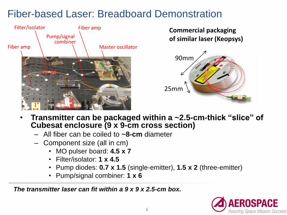
• Transmitter can be packaged within a ~2.5-cm-thick “slice” of Cubesat enclosure (9 x 9-cm cross section) – All fiber can be coiled to ~8-cm diameter
– Component size (all in cm) • MO pulser board: 4.5 x 7
• Filter/isolator: 1 x 4.5
• Pump diodes: 0.7 x 1.5 (single-emitter), 1.5 x 2 (three-emitter)
• Pump/signal combiner: 1 x 6
Fiber amp
Fiber amp
Master oscillator
Filter/isolator
Pump/signal combiner
1”
Commercial packaging of similar laser (Keopsys)
90mm
25mm
Fiber-based Laser: Breadboard Demonstration
The transmitter laser can fit within a 9 x 9 x 2.5-cm box.

7
• Preliminary test parameters
– Pulse rep. rate (PRR) = 1 MHz
– Pulse duration ~ 5ns
• Performance – Output power ~ 14.7 W
– Front end EO efficiency ~ 25.4%
• ~ 56W input power
– Single-frequency output
• Comments – Pulser supports PRRs >500MHz
– Front end expected to perform
identically at PRRs > 1MHz
• Fiber amplifiers act as CW
sources at these high PRRs
Fiber-based Laser: Breadboard Transmitter Performance
The transmitter laser can produce 14.7-W of output power with 56-W input power. It’s
capable of >100-MHz modulation.
8
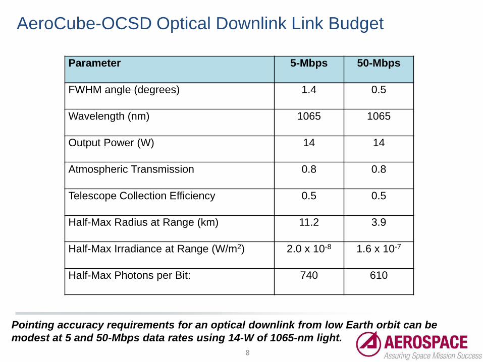
Parameter 5-Mbps 50-Mbps
FWHM angle (degrees) 1.4 0.5
Wavelength (nm) 1065 1065
Output Power (W) 14 14
Atmospheric Transmission 0.8 0.8
Telescope Collection Efficiency 0.5 0.5
Half-Max Radius at Range (km) 11.2 3.9
Half-Max Irradiance at Range (W/m2) 2.0 x 10⁻⁸ 1.6 x 10⁻⁷
Half-Max Photons per Bit: 740 610
AeroCube-OCSD Optical Downlink Link Budget
Pointing accuracy requirements for an optical downlink from low Earth orbit can be
modest at 5 and 50-Mbps data rates using 14-W of 1065-nm light.

9
Satellite Attitude Control for Laser Downlink
• PSSCT-2 demonstrated 5o pointing accuracy
• AeroCube-4 demonstrated 3o pointing accuracy - Two sun sensors and 1 Earth sensor array
- 1-axis of magnetometer missing
- MEMS rate gyro ineffective due to helium absorption
• AeroCube-5 will demonstrate higher accuracy -1o accuracy when sun and Earth are simultaneously visible
- 2o accuracy after 10 minutes of gyro bias measurement, followed by 20-
minutes of gyro control
• AeroCube-OCSD should have 0.5o or better pointing accuracy - Multiple new Earth horizon sensors with 0.5o accuracy
- Multiple sun sensors with 0.1o accuracy
- New single-chip 3-axis magnetometer to provide orthogonal axes
- MEMS rate gyro fills in between optical fixes
- Star tracker experiment with better than 0.1o accuracy
We have already demonstrated 3o pointing accuracy with 1U AeroCubes.
AeroCube-OCSD will have at least 6 times better pointing accuracy.

10
Example tracking of the Moon by AeroCube-4

11
AC-4 tracking a ground point
• Dunsborough, West Australia
• 20 seconds between photographs
T=0s T=20s T=40s T=60s
T=80s T=100s T=120s T=140s
T=160s T=180s T=200s T=220s
We have already flight tested ground-tracking attitude control routines using
AeroCube-4.
Flight Path
12
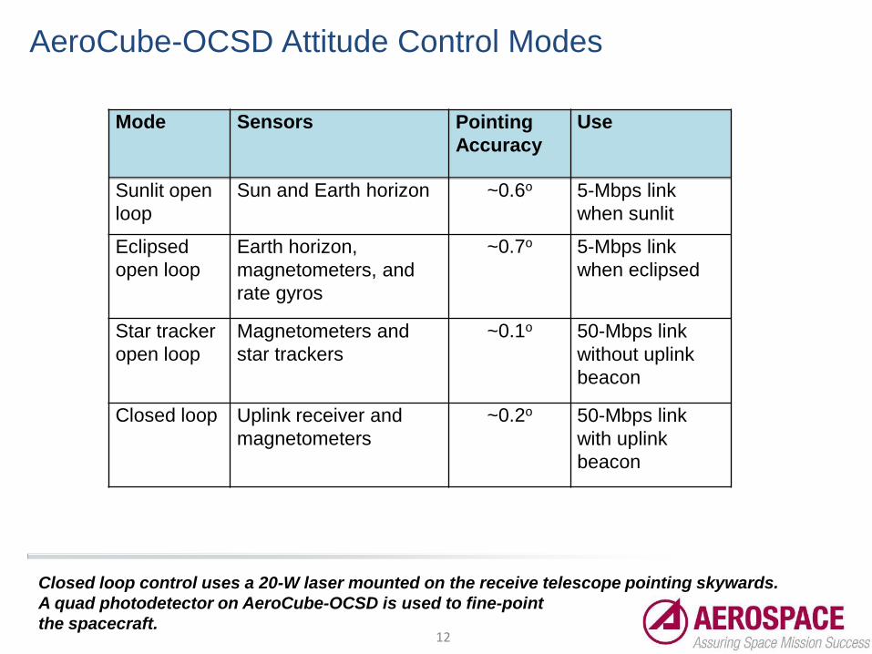
AeroCube-OCSD Attitude Control Modes
Closed loop control uses a 20-W laser mounted on the receive telescope pointing skywards.
A quad photodetector on AeroCube-OCSD is used to fine-point
the spacecraft.
Mode Sensors Pointing
Accuracy
Use
Sunlit open
loop
Sun and Earth horizon ~0.6o 5-Mbps link
when sunlit
Eclipsed
open loop
Earth horizon,
magnetometers, and
rate gyros
~0.7o 5-Mbps link
when eclipsed
Star tracker
open loop
Magnetometers and
star trackers
~0.1o 50-Mbps link
without uplink
beacon
Closed loop Uplink receiver and
magnetometers
~0.2o 50-Mbps link
with uplink
beacon

13
AeroCube-OCSD will have at least a 4:1 variation in ballistic coefficient to provide
propellantless orbit rephasing and altitude changes.
AeroCube-OCSD Variable Drag: Orbit Modification

14
• The Aerospace Corporation thruster module – Additively-manufactured
– 20 mN maximum thrust
– Flown on MEPSI (STS-116) using xenon
• AeroCube-OCSD will use a modified design - Water propellant (<1 atm. storage pressure)
- 2 mN maximum thrust
- 10 m/s DV
The Aerospace Corp. flew the first additively-manufactured propulsion module in 2006.
Cold Gas Propulsion Module
15
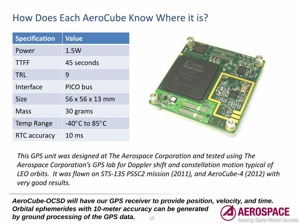
How Does Each AeroCube Know Where it is?
Specification Value
Power 1.5W
TTFF 45 seconds
TRL 9
Interface PICO bus
Size 56 x 56 x 13 mm
Mass 30 grams
Temp Range -40C to 85C
RTC accuracy 10 ms
This GPS unit was designed at The Aerospace Corporation and tested using The Aerospace Corporation’s GPS lab for Doppler shift and constellation motion typical of LEO orbits. It was flown on STS-135 PSSC2 mission (2011), and AeroCube-4 (2012) with very good results.
AeroCube-OCSD will have our GPS receiver to provide position, velocity, and time.
Orbital ephemerides with 10-meter accuracy can be generated
by ground processing of the GPS data.
16
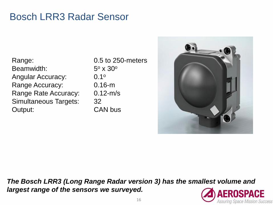
Bosch LRR3 Radar Sensor
Range: 0.5 to 250-meters
Beamwidth: 5o x 30o
Angular Accuracy: 0.1o
Range Accuracy: 0.16-m
Range Rate Accuracy: 0.12-m/s
Simultaneous Targets: 32
Output: CAN bus
The Bosch LRR3 (Long Range Radar version 3) has the smallest volume and
largest range of the sensors we surveyed.

17
AeroCube-OCSD Proximity Operations
AeroCube-OCSD will also have a cold gas propulsion system to enable proximity
operations for testing the radar and optical flow sensors.
18
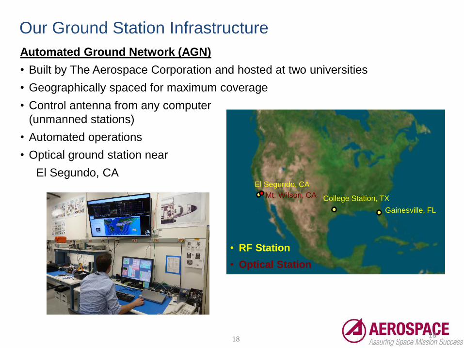
Our Ground Station Infrastructure
18
Automated Ground Network (AGN)
• Built by The Aerospace Corporation and hosted at two universities
• Geographically spaced for maximum coverage
• Control antenna from any computer
(unmanned stations)
• Automated operations
• Optical ground station near
El Segundo, CA El Segundo, CA
Gainesville, FL
College Station, TX Mt. Wilson, CA
• RF Station
• Optical Station

19
Summary • A CubeSat optical communications flight experiment
sponsored by NASA’s Small Satellite Technology Program
- Initiated September 1, 2012
- Flight demonstration in fourth quarter 2014 or first quarter 2015
• The optical downlink will demonstrate 5-Mbps and higher rates
- Ground receiver is a 30-cm diameter telescope
- 50-Mbps should be possible
• Other payloads include a commercial off-the-shelf radar and
an optical mouse sensor
- Radar sensor is an automotive adaptive cruise control radar
- Optical mouse chip tracks angular rates of target spacecraft
• We will demonstrate variable drag orbit rephasing and
altitude modification, and proximity operations
- Proximity operations for the radar and optical mouse sensors
- Cold gas thruster module
All trademarks, service marks, and trade names are the
property of their respective owners